coulomb drag devices: electric solar wind sail propulsion
TRANSCRIPT

COULOMB DRAG DEVICES: ELECTRIC SOLAR WIND SAILPROPULSION AND IONOSPHERIC DEORBITING
Pekka Janhunen
Finnish Meteorological Institute, POB–503, FI–00101, Helsinki, Finland
Abstract
A charged tether or wire experiences Coulomb dragwhen inserted into flowing plasma. In the solarwind the Coulomb drag can be utilised as efficientpropellantless interplanetary propulsion as the elec-tric solar wind sail (electric sail, E-sail). In lowEarth orbit (LEO) the same plasma physical effectcan be utilised for efficient low-thrust deorbiting ofspace debris objects (the plasma brake). The E-sail is rotationally stabilised while the deorbitingCoulomb drag devices can be stabilised either byspinning or by Earth’s gravity gradient.
According to numerical estimates, Coulomb dragdevices have very promising performance figures,both for interplanetary propulsion and for deorbit-ing in LEO. Much of the technology is common toboth applications. E-sail technology developmentwas carried out in ESAIL FP7 project (2011-2013)which achieved TRL 4-5 for key hardware compo-nents that can enable 1 N class interplanetary E-sail weighing less than 200 kg. The thrust of theE-sail scales as inverse solar distance and its powerconsumption (nominally 700 W/N at 1 au) scales asthe inverse distance squared. As part of the ESAILproject, a continuous 1 km sample of E-sail tetherwas produced by an automatic and scalable “tetherfactory”. The manufacturing method uses ultra-sonic wire to wire bonding which was developedfrom ordinary wire to plate bonding for the E-sailpurpose. Also a “Remote Unit” device which takescare of deployment and spin rate control was proto-typed and successfully environmentally tested. OurRemote Unit prototype is operable in the solar dis-tance range of 0.9-4 au.
The 1-U CubeSat ESTCube-1 was launched inMay 2013 and it will try to measure the Coulombdrag acting on a 10 m long tether in LEO whencharged to 500 V positive or negative. A more ad-vanced version of the experiment with 100 m tetheris under preparation and will be launched in 2015with the Aalto-1 3-U CubeSat to polar LEO.
1 Introduction
The concept of solar wind electric sail (electric sail,E-sail, Fig. 1) was proposed as a device which har-nesses the momentum flux of the natural solar wind[1, 2]. The first attempt to predict the thrustper unit tether length was based on electrostaticparticle-in-cell (PIC) simulations [2]. The initialthrust estimate was later corrected upward [3].
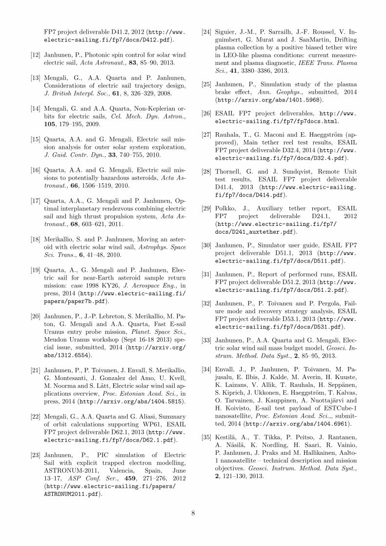
It was realised that not only a positive, but alsoa negative tether would produce a Coulomb drageffect [4]. As a new application for the technology,it was proposed that a single gravity-stabilised neg-atively biased tether could be used for satellite andspace debris deorbiting in low Earth orbit (LEO)[5] (Fig. 2).
The E-sail has potentially revolutionary perfor-mance level in comparison to other propulsion sys-tems [6]. The tether weighs only 10 grams per kilo-metre and produces a thrust of ∼ 0.5 mN/km at1 au distance. The E-sail thrust scales as propor-tional to 1/r where r is the solar distance. Thereason is that while the solar wind dynamic pres-sure decays as ∼ 1/r2, the plasma Debye length(by which the electric field penetration distance andhence the virtual sail size scales) varies as ∼ r, thusgiving an overall 1/r dependence for the thrust. Forexample, hundred 20 km long tethers would weigh20 kg and they would produce 1 N thrust at 1 auwhich gives a 30 km/s velocity change pear year fora 1000 kg spacecraft.
E-sail thrust magnitude can be easily controlledbetween zero and a maximum value by changingthe voltage of the tethers. The tether voltage ismaintained by continuously operating an electrongun which pumps out negative charge from the sys-tem, hence tether voltage can be actuated easilyby changing the current and voltage of the electrongun beam. The power consumption of the elec-tron gun is moderate (700 W nominally at 1 au forlarge 1 N sail) and it scales as 1/r2, i.e. in the sameway as the illumination power of solar panels. The
1
arX
iv:1
404.
7430
v2 [
astr
o-ph
.IM
] 2
8 Se
p 20
14
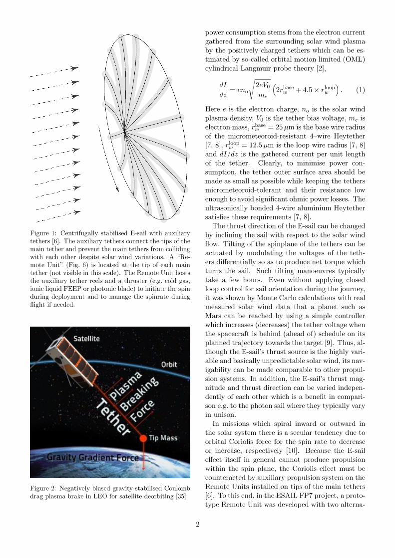
Figure 1: Centrifugally stabilised E-sail with auxiliarytethers [6]. The auxiliary tethers connect the tips of themain tether and prevent the main tethers from collidingwith each other despite solar wind variations. A “Re-mote Unit” (Fig. 6) is located at the tip of each maintether (not visible in this scale). The Remote Unit hoststhe auxiliary tether reels and a thruster (e.g. cold gas,ionic liquid FEEP or photonic blade) to initiate the spinduring deployment and to manage the spinrate duringflight if needed.
Figure 2: Negatively biased gravity-stabilised Coulombdrag plasma brake in LEO for satellite deorbiting [35].
power consumption stems from the electron currentgathered from the surrounding solar wind plasmaby the positively charged tethers which can be es-timated by so-called orbital motion limited (OML)cylindrical Langmuir probe theory [2],
dI
dz= eno
√2eV0
me
(2rbase
w + 4.5× rloopw
). (1)
Here e is the electron charge, no is the solar windplasma density, V0 is the tether bias voltage, me iselectron mass, rbase
w = 25µm is the base wire radiusof the micrometeoroid-resistant 4–wire Heytether[7, 8], rloop
w = 12.5µm is the loop wire radius [7, 8]and dI/dz is the gathered current per unit lengthof the tether. Clearly, to minimise power con-sumption, the tether outer surface area should bemade as small as possible while keeping the tethersmicrometeoroid-tolerant and their resistance lowenough to avoid significant ohmic power losses. Theultrasonically bonded 4-wire aluminium Heytethersatisfies these requirements [7, 8].
The thrust direction of the E-sail can be changedby inclining the sail with respect to the solar windflow. Tilting of the spinplane of the tethers can beactuated by modulating the voltages of the teth-ers differentially so as to produce net torque whichturns the sail. Such tilting manoeuvres typicallytake a few hours. Even without applying closedloop control for sail orientation during the journey,it was shown by Monte Carlo calculations with realmeasured solar wind data that a planet such asMars can be reached by using a simple controllerwhich increases (decreases) the tether voltage whenthe spacecraft is behind (ahead of) schedule on itsplanned trajectory towards the target [9]. Thus, al-though the E-sail’s thrust source is the highly vari-able and basically unpredictable solar wind, its nav-igability can be made comparable to other propul-sion systems. In addition, the E-sail’s thrust mag-nitude and thrust direction can be varied indepen-dently of each other which is a benefit in compari-son e.g. to the photon sail where they typically varyin unison.
In missions which spiral inward or outward inthe solar system there is a secular tendency due toorbital Coriolis force for the spin rate to decreaseor increase, respectively [10]. Because the E-saileffect itself in general cannot produce propulsionwithin the spin plane, the Coriolis effect must becounteracted by auxiliary propulsion system on theRemote Units installed on tips of the main tethers[6]. To this end, in the ESAIL FP7 project, a proto-type Remote Unit was developed with two alterna-
2

Figure 3: PIC simulation of positively charged E-sailtether interacting with streaming solar wind plasma [23].Solar wind (density 7.3 cm−3, speed 400 km/s) arrivesfrom the left and interacts with +5.6 kV charged tetherat (white dot).
tive propulsion systems (cold gas and ionic liquidFEEP) [11]. Photonic blade auxiliary propulsiondevices have also been considered for this task [12].
The E-sail has potentially revolutionary level ofperformance and hence it has a large number ofapplications in solar system missions [13, 14, 15,16, 17, 18, 19, 20]. The various E-sail solar sys-tem applications are discussed and summarised by[21] and a readable yet rigorous presentation of themission possibilities from the orbital calculationsperspective is available [22].
2 Physics of Coulomb drag
When plasma streams past a charged thin tether,the tether’s electric field penetrates some distanceinto the plasma and deflects the charged particlesof the stream. Because electrons are lightweight,the momentum flux carried by them is negligibleso it is enough to consider the deflection of ions.Both positively and negatively biased tethers causeion deflection and hence Coulomb drag. A positivetether deflects positively charged ions by repellingthem (Fig. 3). A negative tether deflects ions byattracting them so that their paths cross behindthe tether (Fig. 4).
2.1 Positively biased tether
A positively biased tether repels stream ions andattracts electrons. When the potential is turnedon, a population of trapped electrons gets formed[2]. In most of the literature concerning biasedtethers, it is implicitly or explicitly assumed thattrapped electrons are not present in the asymp-totic state. In a multi-tether starfish-shaped E-sail geometry (Fig. 1), trapped electron orbits arechaotised whenever the electron visits the central
Figure 4: Electron density (a) and ion density (b) nor-malised to plasma stream density in the final state(t = 2.43 ms) in LEO conditions [25]. Flow arrives fromthe right.
“hub” which is the spacecraft, and chaotised elec-trons have a small nonzero probability of gettinginjected into an orbit which takes them to colli-sion course with a tether wire so that trapped elec-trons are removed by this mechanism in few minutetimescale in nominal 1 au solar wind [3]. It mightbe that other processes such as plasma waves occurin nature which speed up the process. By PIC sim-ulations alone it is not easy to predict how much ifany trapped electrons are present in the final state.
The E-sail thrust per tether length dF/dz isgiven by
dF
dz= KPdynrs (2)
where K is a numerical coefficient of order unity,Pdyn = ρv2 is the dynamic pressure of the plasmaflow and rs is the radius of the electron sheath (thepenetration distance of the electric field into the
3

plasma). The quantity rs can be inferred from re-cent laboratory measurements of Siguier et al. [24]where Ar+ plasma (ion mass mi = 40 u) of den-sity no = 2.4 · 1011 m−3 accelerated to 20 eV bulkflow energy (hence speed v = 9.8 km/s) was usedand let to interact with rw = 2.5 mm radius metaltether biased to V0 = 100 V and 400 V in two ex-periments. At V0 = 100 V the sheath radius asvisually determined from their Figure 7 is rs = 12cm and at 400 V it is rs = 28 cm (from their Figure8). For estimating the corresponding dF/dz, let usassume K = 2 in the above formula [Eq. (2)]. Thiscorresponds to assuming that ions incident on thesheath are on average deflected by 90◦ (notice thatthe size of the virtual obstacle made by the sheathis twice its radius). We think that this is a rea-sonable first estimate since ions arriving head-ontowards the tether are reflected backwards whileions arriving near the boundaries of the sheath areprobably deflected by less than 90◦. In their exper-iment Pdyn = 1.54 µPa so Eq. 2 gives dF/dz = 370nN/m and dF/dz = 860 nN/m for V0 equal to 100V and 400 V, respectively.
Let us compare these experimentally inferred val-ues with theoretical estimates. A simple theoreticalestimate for the sheath radius is the effective Debyelength
λeffD =
√ε0 (V0 − V1)
eno(3)
where V1 = (1/2)miv2/e is the stream ion bulk
flow energy. The expression (3) for the effectiveDebye length is obtained from the usual formulafor ordinary electron Debye length by replacing theelectron temperature by the tether voltage. We alsosubtract the bulk energy term V1 to model the factthat if the tether voltage is lower than the bulkenergy, it can no longer reflect back or stop ionsbut only weakly deflects them even if they arrivewith zero boost parameter; the subtraction of V1
however has only modest impact to our results. Ifone takes rs to be equal to λeff
D in Eq. (2), oneobtains dF/dz equal to 420 nN/m and 910 nN/mfor V0 equal to 100 V and 400 V, respectively.
Theoretical E-sail thrust formulas of [6] containthe average electron density ne inside the sheathas a free parameter, the choice ne = 0 giving thelargest E-sail thrust. Assuming ne = 0 and apply-ing the formulas for the experimental parameters ofSiguier et al. [24], one obtains 220 nN/m and 740nN/m thrust per length for V0 equal to 100 V and400 V, respectively.
We summarise the experimental and theoreticalresults in Table 1.
Table 1: Comparison of experimental and theoreticalE-sail thrust per length in LEO-like conditions.
V0=100 V V0=400 V
Siguier et al. [24] 370 nN/m 860 nN/mλeffD , Eq. 3 420 nN/m 910 nN/m
Theory of [6] /w ne=0 220 nN/m 740 nN/m
We conclude from Table 1 that experimental re-sults of [24] are consistent with the assumption ofno trapped electrons, i.e. maximal E-sail thrust.
2.2 Negatively biased tether
In the negative polarity case, electrons are simplyrepelled by the tether (Fig. 4) and hence the physicsof electrons is simple. We believe that PIC simu-lations therefore have a good chance of predictingthe thrust correctly in the negative polarity case.Using a new supercomputer, a comprehensive setof negative polarity PIC simulations for LEO-likeparameters was recently conducted [25] and it wasfound that the following formula gives a good fit tothe PIC simulations:
dF
dz= 3.864× Pdyn
√εoV
enoexp
(−Vi/V
). (4)
Here vo is the ionospheric plasma ram flow speedrelative to spacecraft (assumed to be perpendicularto the tether or else vo denotes only the perpendicu-lar component), Pdyn = minov
2o is the flow dynamic
pressure, mi is the ion mass (typically the plasmais singly ionised atomic oxygen so that mi ≈ 16 u),
V =|V0|
ln(λeffD /r
∗w), (5)
r∗w is the tether’s effective electric radius (AppendixA of [2]), λeff
D =√εo|V0|/(eno) is the effective Debye
length and Vi = (1/2)miv2o/e is the bulk ion flow
energy in voltage units. The effective electric radiusis approximately given by r∗w =
√brw ≈ 1 mm,
where rw is the tether wire radius, typically 12.5-25 µm, and b is the tether width, typically 2 cm(a rough value of b is sufficient to know because r∗wenters into Eq. (4) only logarithmically).
Thus, although experimental confirmation isneeded, there is good reason to believe that Eq. 4describes LEO plasma brake thrust well. The onlyexception is that if the geomagnetic field is predom-inantly oriented along the tether, the interactionbecomes turbulent and the thrust is moderatelyreduced [25]. The reduction grows with increas-ing voltage: it is 17% at −320 V bias voltage and
4

Figure 5: 1 km tether (mass 11 grams) on its ∅ = 5 cmreel [8].
Figure 6: ESAIL project Remote Unit prototype [11].
27% at −760 V. For a vertical gravity-stabilisedplasma brake tether in polar orbit, efficiency re-duction with respect to Eq. (4) is thus expected athigh latitudes.
We emphasise that Eq. (4) has thus far only beenverified with simulations in LEO plasma environ-ment conditions. If negative polarity Coulomb dragdevices would become relevant in the future also inother plasma conditions, the applicability of Eq. (4)should be considered carefully on a case by case ba-sis.
3 E-sail development
The goal of ESAIL FP7 project (2011-2013) wasto develop prototypes of key components of a 1 NE-sail at technical readiness level (TRL) 4-5 [26].The main achievements were the following:
• Demonstrated manufacturing of 1 km contin-uous 4-wire E-sail tether (Fig. 5, [8]).
Figure 7: Screenshot from E-sail dynamical simulator[30].
• Demonstrated successful reel-out of 100 mtether at low (0.25 gram) tension, also afterreel was shaken in launch vibration test facil-ity [27].
• Built and tested low-mass prototype RemoteUnit with 0.9-4 au operational range (Fig. 6,[11, 28]).
• Proposed and prototyped solution for auxiliarytether (perforated kapton tape, [29]).
• E-sail “flight simulator” software (Fig. 7, [30,31]), E-sail failure mode and recovery strat-egy analysis [32], E-sail mass budget estima-tion [33], applications [22].
These achievements suggest that a large-scale(up to 1 N) E-sail is feasible to build. While a lotof work certainly remains to be done before a large-scale E-sail becomes a reality, no unsolved technicalproblems are currently known.
4 Plasma brake development
Recall from section 2.2 that for LEO parameters,Eq. 4 is a good fit to PIC simulations (except formodest thrust reduction due to turbulence whenthe dominant component of the geomagnetic fieldis along the tether) which in turn are expectedlygood models of reality in case of negative tethervoltage.
One noteworthy fact is that LEO plasma brakethrust according to Eq. 4 is proportional (throughlinear dependence on Pdyn) to the ion mass mi.Thus, plasma brake thrust is 16 times larger in pureoxygen O◦ plasma than in pure proton plasma.
5

Table 2: Predicted plasma brake thrust (nN/m) for solarmin/solar max conditions.
Altitude MLT 12-00 MLT 06-18 Average
700 km 47/157 42/140 44/149800 km 33/117 30/108 32/112900 km 25/88 22/84 23/86
For example, at V0 = −1 kV, no = 3 · 1010 m−3,v = 7.5 km/s and mi = 16 u, Eq. 4 gives 85 nN/mthrust. In the negative bias case, usable tether volt-age is limited by onset of electron field emission.We think that above 1-2 kV, field emission mightstart to become an issue.
Table 2 gives plasma brake thrust based on Eq. 4,assuming V0 = −1 kV, v = 7.5 km/s and us-ing plasma density and chemical composition takenfrom the IRI-2012 ionospheric model, for noon-midnight (mean local time MLT 12-00) and dawn-dusk (MLT 06-18) polar orbits and for solar mini-mum and maximum ionospheric conditions. We seefrom Table 2 that the dependence on solar cycle isrelatively significant, about factor 3.5. The solarcycle dependence is due to increased plasma den-sity and increased oxygen abundance during solarmaximum conditions. There is obviously also an al-titude dependence. Below 700 km the thrust wouldcontinue to increase until ∼ 400−500 km, providedthat the hardware is designed to take advantage ofit. The dependence on MLT is weak.
As a numeric example, consider a 10 km longplasma brake tether which starts bringing down adebris object of 200 kg mass from 800 km circularorbit in an MLT which is average between dawn-dusk and noon-midnight. The required ∆v from800 km to 700 km is 53.5 m/s and from 700 kmto 400 km 165 m/s. During solar minimum, deor-biting from 800 km to 700 km takes 0.88 years andthe rest from 700 km to 400 km (assuming the samethrust as at 700 km) takes 2.4 years, thus altogether3.25 years. During solar maximum the 800→700km deorbiting takes 0.25 years and 700→400 km0.7 years, thus altogether 0.96 years. These esti-mates are conservative since in reality plasma den-sity and oxygen concentration and hence plasmabrake thrust continue to grow below 700 km.
5 ESTCube and Aalto test missions
The ESTCube-1 nanosatellite (1 kg, 1-U Cube-Sat) was launched in May 7, 2013 onboard Vegafrom Kourou, French Guiana. The primary pay-load of ESTCube-1 is a Coulomb drag experiment
Figure 8: Left: ESTCube-1 Coulomb drag experimentpayload (10x10 cm circuit board), Right: ESTCube-11-U CubeSat. Photographs by Jouni Envall and TartuObservatory.
[34] and the goal of the mission is to measure theCoulomb drag force acting on its 10 m long tether inLEO conditions (670 km altitude polar orbit). Thesatellite can polarise the tether to ±500 V, henceboth E-sail (positive polarity) and plasma brake(negative polarity) experiments can be carried out.The positive mode uses nanographite electron gunswhile the negative mode in this case needs only avoltage source which creates a potential differencebetween the tether and the satellite body: electroncollection by the satellite’s conducting parts canbalance the ion current gathered by the tether.
The ESTCube-1 tether experiment has not yetbeen started. The satellite is otherwise workingfine, but there are some technical issues with its at-titude control system. Work is ongoing to resolvethose issues by software and we hope to be able tocarry out the tether experiment soon. All aspectsof ESTCube-1 are documented in an ESTCube-1 special issue of the Proceedings of the EstonianAcademy of Sciences which is expected to appearin late May 2014.
Aalto-1 is a Finnish 3-U CubeSat which will belaunched in 2015 [35]. Aalto-1 carries (among otherthings) a 100 m long Coulomb drag tether exper-iment. The work of building the satellite and thepayload is proceeding at an advanced stage.
6 Technology roadmap
The E-sail and the plasma brake have a lot of tech-nical synergy. The baseline concept is that theinterplanetary E-sail uses positive voltages, elec-tron gun and multiple centrifugally stabilised teth-ers while the plasma brake uses vertical gravity-stabilised tether(s), negative voltage and no elec-tron or ion gun (a relatively small conducting ob-ject being enough to gather the balancing electroncurrent in that case). However, it is not impossibleto combine the elements of the technology also in
6

other ways.
One LEO CubeSat experiment (ESTCube-1) isalready in orbit and another one (Aalto-1) is beingbuilt. If these experiments are technically success-ful, they will demonstrate deployment of 10 m and100 m tether, respectively, and will measure thestrength of negative and positive polarity Coulombdrag effects in LEO plasma conditions.
Our current plan for the next step is to fly a 3-U CubeSat experiment (ESTCube-3) in solar windintersecting orbit which measures the E-sail effectwith a 1 km long tether using 5-10 kV voltage.Because launch opportunities to solar wind inter-secting orbit (for example a lunar orbit) are lessfrequent than ordinary LEO CubeSat launches, toensure mission success we plan to prove the satel-lite’s technologies by first flying an identical satel-lite (ESTCube-2) in LEO. ESTCube-2 also natu-rally demonstrates a 1 km long plasma brake. Af-ter ESTCube-3, we will have a measurement of thestrength of the E-sail effect in the actual environ-ment (solar wind), a demonstration of deploying a1 km long tether and a demonstration of using theE-sail effect for spacecraft propulsion.
After ESTCube-3, we need an E-sail“pathfinder” mission (comparable to SMART-1in its philosophy) which tests the use of E-sailpropulsion for going to some target and carriessome payload. For example, it could be a NEOmission equipped with imaging instruments.
7 Discussion and conclusions
Scaling up the manufacturing capacity of tethersand demonstrating their robust deployment in lab-oratory and in space is important and serves allapplications of Coulomb drag devices. For the E-sail, a specific challenge for raising the TRL is toget affordable launch opportunities into the rele-vant environment i.e. the solar wind. Demonstra-tion of multi-tether centrifugal deployment is im-portant as well, but it can be rather well simulatednumerically and can also be demonstrated in LEO.
In conclusion, the development of Coulomb dragdevices (E-sail and plasma brake) has gone well andtheir performance and other characteristics lookvery promising. While the possibility of negativesurprises can never be excluded, presently we arenot aware of any unsolved issues that could makeit difficult to construct efficient plasma brake deor-biting devices and production scale interplanetaryE-sails.
Acknowledgements. This research was financed
within the European Community’s Seventh Frame-work Programme ([FP7/2007-2013]) under grantagreement number 262733 and the Academy of Fin-land grant decision 250591.
References
[1] Janhunen, P., Electric sail for spacecraft propul-sion, J. Prop. Power, 20, 763–764, 2004.
[2] Janhunen, P. and A. Sandroos, Simulation study ofsolar wind push on a charged wire: basis of solarwind electric sail propulsion, Ann. Geophys., 25,755–767, 2007.
[3] Janhunen, P., Increased electric sail thrust throughremoval of trapped shielding electrons by orbitchaotisation due to spacecraft body, Ann. Geo-phys., 27, 3089–3100, 2009.
[4] Janhunen, P., On the feasibility of a negative po-larity electric sail, Ann. Geophys., 27, 1439–1447,2009.
[5] Janhunen, P., Electrostatic plasma brake for de-orbiting a satellite, J. Prop. Power, 26, 370–372,2010.
[6] Janhunen, P., P.K. Toivanen, J. Polkko,S. Merikallio, P. Salminen, E. Haeggstrom,H. Seppanen, R. Kurppa, J. Ukkonen, S. Kiprich,G. Thornell, H. Kratz, L. Richter, O. Kromer,R. Rosta, M. Noorma, J. Envall, S. Latt, G. Men-gali, A.A. Quarta, H. Koivisto, O. Tarvainen,T. Kalvas, J. Kauppinen, A. Nuottajarvi andA. Obraztsov, Electric solar wind sail: Towardstest missions, Rev. Sci. Instrum., 81, 111301,2010.
[7] Seppanen, H., S. Kiprich, R. Kurppa, P. Janhunenand E. Haeggstrom, Wire-to-wire bonding of um-diameter aluminum wires for the Electric SolarWind Sail, Microelectronic Engineering, 88, 3267–3269, 2011.
[8] Seppanen, H., T. Rauhala, S. Kiprich, J. Ukko-nen, M. Simonsson, R. Kurppa, P. Janhunenand E. Haeggstrom, One kilometer (1 km) elec-tric solar wind sail tether produced automatically,Rev. Sci. Instrum., 84, 095102, 2013.
[9] Toivanen, P.K. and P. Janhunen, Electric sail-ing under observed solar wind conditions, Astro-phys. Space Sci. Trans., 5, 61–69, 2009.
[10] Toivanen, P. and P. Janhunen, Spin plane controland thrust vectoring of electric solar wind sail bytether potential modulation, J. Prop. Power, 29,178–185, 2013.
[11] Wagner, S., J. Sundqvist and G. Thornell, De-sign description of the Remote Unit, ESAIL
7
FP7 project deliverable D41.2, 2012 (http://www.electric-sailing.fi/fp7/docs/D412.pdf).
[12] Janhunen, P., Photonic spin control for solar windelectric sail, Acta Astronaut., 83, 85–90, 2013.
[13] Mengali, G., A.A. Quarta and P. Janhunen,Considerations of electric sail trajectory design,J. British Interpl. Soc., 61, 8, 326–329, 2008.
[14] Mengali, G. and A.A. Quarta, Non-Keplerian or-bits for electric sails, Cel. Mech. Dyn. Astron.,105, 179–195, 2009.
[15] Quarta, A.A. and G. Mengali, Electric sail mis-sion analysis for outer solar system exploration,J. Guid. Contr. Dyn., 33, 740–755, 2010.
[16] Quarta, A.A. and G. Mengali, Electric sail mis-sions to potentially hazardous asteroids, Acta As-tronaut., 66, 1506–1519, 2010.
[17] Quarta, A.A., G. Mengali and P. Janhunen, Op-timal interplanetary rendezvous combining electricsail and high thrust propulsion system, Acta As-tronaut., 68, 603–621, 2011.
[18] Merikallio, S. and P. Janhunen, Moving an aster-oid with electric solar wind sail, Astrophys. SpaceSci. Trans., 6, 41–48, 2010.
[19] Quarta, A., G. Mengali and P. Janhunen, Elec-tric sail for near-Earth asteroid sample returnmission: case 1998 KY26, J. Aerospace Eng., inpress, 2014 (http://www.electric-sailing.fi/papers/paper7b.pdf).
[20] Janhunen, P., J.-P. Lebreton, S. Merikallio, M. Pa-ton, G. Mengali and A.A. Quarta, Fast E-sailUranus entry probe mission, Planet. Space Sci.,Meudon Uranus workshop (Sept 16-18 2013) spe-cial issue, submitted, 2014 (http://arxiv.org/abs/1312.6554).
[21] Janhunen, P., P. Toivanen, J. Envall, S. Merikallio,G. Montesanti, J. Gonzalez del Amo, U. Kvell,M. Noorma and S. Latt, Electric solar wind sail ap-plications overview, Proc. Estonian Acad. Sci., inpress, 2014 (http://arxiv.org/abs/1404.5815).
[22] Mengali, G., A.A. Quarta and G. Aliasi, Summaryof orbit calculations supporting WP61, ESAILFP7 project deliverable D62.1, 2013 (http://www.electric-sailing.fi/fp7/docs/D62.1.pdf).
[23] Janhunen, P., PIC simulation of ElectricSail with explicit trapped electron modelling,ASTRONUM-2011, Valencia, Spain, June13–17, ASP Conf. Ser., 459, 271–276, 2012(http://www.electric-sailing.fi/papers/ASTRONUM2011.pdf).
[24] Siguier, J.-M., P. Sarrailh, J.-F. Roussel, V. In-guimbert, G. Murat and J. SanMartin, Driftingplasma collection by a positive biased tether wirein LEO-like plasma conditions: current measure-ment and plasma diagnostic, IEEE Trans. PlasmaSci., 41, 3380–3386, 2013.
[25] Janhunen, P., Simulation study of the plasmabrake effect, Ann. Geophys., submitted, 2014(http://arxiv.org/abs/1401.5968).
[26] ESAIL FP7 project deliverables, http://www.
electric-sailing.fi/fp7/fp7docs.html.
[27] Rauhala, T., G. Maconi and E. Haeggstrom (ap-proved), Main tether reel test results, ESAILFP7 project deliverable D32.4, 2014 (http://www.electric-sailing.fi/fp7/docs/D32.4.pdf).
[28] Thornell, G. and J. Sundqvist, Remote Unittest results, ESAIL FP7 project deliverableD41.4, 2013 (http://www.electric-sailing.fi/fp7/docs/D414.pdf).
[29] Polkko, J., Auxiliary tether report, ESAILFP7 project deliverable D24.1, 2012(http://www.electric-sailing.fi/fp7/docs/D241_auxtether.pdf).
[30] Janhunen, P., Simulator user guide, ESAIL FP7project deliverable D51.1, 2013 (http://www.electric-sailing.fi/fp7/docs/D511.pdf).
[31] Janhunen, P., Report of performed runs, ESAILFP7 project deliverable D51.2, 2013 (http://www.electric-sailing.fi/fp7/docs/D51.2.pdf).
[32] Janhunen, P., P. Toivanen and P. Pergola, Fail-ure mode and recovery strategy analysis, ESAILFP7 project deliverable D53.1, 2013 (http://www.electric-sailing.fi/fp7/docs/D531.pdf).
[33] Janhunen, P., A.A. Quarta and G. Mengali, Elec-tric solar wind sail mass budget model, Geosci. In-strum. Method. Data Syst., 2, 85–95, 2013.
[34] Envall, J., P. Janhunen, P. Toivanen, M. Pa-jusalu, E. Ilbis, J. Kalde, M. Averin, H. Kuuste,K. Laizans, V. Allik, T. Rauhala, H. Seppanen,S. Kiprich, J. Ukkonen, E. Haeggstrom, T. Kalvas,O. Tarvainen, J. Kauppinen, A. Nuottajarvi andH. Koivisto, E-sail test payload of ESTCube-1nanosatellite, Proc. Estonian Acad. Sci.,, submit-ted, 2014 (http://arxiv.org/abs/1404.6961).
[35] Kestila, A., T. Tikka, P. Peitso, J. Rantanen,A. Nasila, K. Nordling, H. Saari, R. Vainio,P. Janhunen, J. Praks and M. Hallikainen, Aalto-1 nanosatellite – technical description and missionobjectives. Geosci. Instrum. Method. Data Syst.,2, 121–130, 2013.
8