cosc 3213 – computer networks i summer 2003 topics: 1. line coding (digital data, digital signals)...
TRANSCRIPT

COSC 3213 – Computer Networks ISummer 2003
Topics:1. Line Coding (Digital Data, Digital Signals)2. Digital Modulation (Digital Data, Analog Signals)3. PCM and Delta Modulation (Analog Data, Digital Signals)4. Analog Modulation (Analog Data, Analog Signals)
Stallings: Sections 5.1 – 5.4

2
Overview
1. Recall
Data: information that needs to be transmitted, e.g. voice signal, binary file.
Signal: waveform used to transmit data, e.g., sine wave or line codes
Some pre-processing stage is needed to convert data into a signal.
2. In this chapter, we will cover four different types of pre-processing techniques
a) Digital Data, digital signal
b) Analog Data, digital signal
Encoding: appropriate representation of data into signals
Decoding: inverse of encoding

3
Overview (2)
c) Digital Data, analog signal
d) Analog Data, analog signal
Modulation: is a process of shifting the frequency content of the signal to a higher frequency. Allows multiple users to use the same channel simultaneously by selecting a different carrier frequency for each user (broadband)
Demodulation: is the inverse of modulation.

4
Line Coding (1)
Line Coding: Converts digital data (a binary sequence) into a digital signal NRZ-L: Bit 0 is represented by a higher level (+A Volts)
Bit 1 is represented by a lower level (0 Volts)
Average transmitted power per pulse = 1/2 x (A2) + 1/2 x (0) = A2 / 2
Average value of signal = A / 2 Volts
1 0 1 0 1 1 0 01
UnipolarNRZ

5
Line Coding (2)
2. NRZI (Nonreturn to Zero Inverted): Bit 0: No transition at beginning of interval Bit 1: Transition at beginning of
interval
Average transmitted power per pulse = A2 / 4
Half the power used as compared to Unipolar NRZ with same distance between levels
Average value of signal = 0 Volts
1 0 1 0 1 1 0 01
UnipolarNRZ
NRZI

6
Line Coding (3)
3. Pseudoternary Bit 0: positive or negative voltage, alternating for successive 0’s Bit 1: no line signal
Average transmitted power per pulse = A2 / 8 if bit 0 and 1 are equiprobable
Average value of signal = 0 Volts
1 0 1 0 1 1 0 01
UnipolarNRZ
NRZI
Pseudoternary

7
Line Coding (4)
4. Bipolar AMI: Bit 0: no line signal Bit 1: positive or negative voltage, alternating for successive 0’s
Average transmitted power per pulse = A2 / 8 if bit 0 and 1 are equiprobable
Average value of signal = 0 Volts
1 0 1 0 1 1 0 01
UnipolarNRZ
NRZI
Pseudoternary
Bipolar AMI

8
Line Coding (5)
5. Manchester:
1 0 1 0 1 1 0 01
UnipolarNRZ
NRZI
Pseudoternary
Bipolar AMI
A/2-A/2
A/2-A/2
Manchester

9
Line Coding (6)
6. Differential Manchester: Always a transition in the middle of intervalBit 1: no transition at beginning of intervalBit 0: transition at beginning of interval
1 0 1 0 1 1 0 01
UnipolarNRZ
NRZI
Pseudoternary
Bipolar AMI
Manchester
DifferentialManchester

10
Comparison of Line Codes (1)
Following are the important selection criterion:
1. Signal Spectrum: Lesser Bandwidth is preferable Lack of dc component is preferable More spectral power in the middle of the spectrum rather than at the edges is
preferable
2. Synchronization: locate the beginning and end of the pulse from the line codes
3. Error detection: Built some error-detection capability in line codes
4. Signal Interference: Make line codes less susceptible to distortion introduced by a second signal sharing the medium.
5. Noise Immunity: Minimize the effect of noise
6. Complexity: Make the encoder and decoder simpler to implement. Low signaling rate typically means lower cost.

11
Comparison of Line Codes: Spectrum (2)
Power spectra of different line coding schemes:
NRZ: Used for lowpass channels. Limitation: DC component
Multilevel Binary: No DC, Same bandwidth required as NRZ, energy concentrated in mid frequencies.
Biphase: No DC; Double BW required
-0.2
0
0.2
0.4
0.6
0.8
1
1.2
0
0.2
0.4
0.6
0.8 1
1.2
1.4
1.6
1.8 2
f / R
pow
er d
ensi
ty
NRZL, NRZI
Multilevel binary (AMI,Bipolar, Pseudot.)
Biphase (Manchester, Diff. Manchester)

12
Comparison of Line Codes (3)
NRZNRZ Multilevel BinaryMultilevel Binary BiphaseBiphase
Bandwidth Smallest Same as NRZ Double of NRZ or Multilevel Binary
DC component Presence of DC component leads to power wastage
Zero DC component Zero DC component
Synchronization String of continuous 0s (and 1s) leads to loss in synchronization
String of continuous 0s (or 1s) leads to loss of synchronization
Transition at middle of pulse allows synchronization
Error Detection No capability No capability Built in capability because of transition
Maximum Modulation Rate
Same as data rate.NRZL: for 1010…NRZI: for 1111…
Same as data rate.Bipolar: for 1111…Pseudo: for 0000…
Double of data rate.For 000…

13
Scrambling Techniques
Recall that Manchester codes are best in terms of synchronization and error detection capabilities but require twice the bandwidth as compared to Multilevel Binary.
Is it possible to include synchronization bits within the waveforms of Multilevel Binary? Yes! Sequences that result in a constant voltage level are replaced in part by filling
segments that provide transitions (Scrambling). Example: Bipolar AMI – Replace strings of 0’s that result in 0 volts (B8ZS or HDB3) Bipolar with 8 zeros substitution (B8ZS):
Replace an octet of eight zeros with if the last voltage level was positiveReplace an octet of eight zeros with if the last voltage level was negative
Bipolar- AMI
1 0 0 0 0 0 0 00 1
1 0 0 0 0 1
B8ZS

14
Digital Data, Analog Signal – ASK (1)
Amplitude Shift Keying (ASK):
Information 1 1 1 10 0
0 T 2T 3T 4T 5T 6TASK t
0binary
1binary
0
)2sin()(
tfAts c

15
Digital Data, Analog Signal – FSK (2)
Frequency Shift Keying (FSK):
Information 1 1 1 10 0
0 T 2T 3T 4T 5T 6TASK t
0 T 2T 3T 4T 5T 6TFSK t
0binary
1binary
)2sin(
)2sin()(
2
1
tfA
tfAts

16
Digital Data, Analog Signal – PSK (3)
Phase Shift Keying (PSK):
Information 1 1 1 10 0
0 T 2T 3T 4T 5T 6TFSK t
0 T 2T 3T 4T 5T 6TASK t
0 T 2T 3T 4T 5T 6TPSK t
0binary
1binary
)2sin(
)2sin()(
tfA
tfAts
c
c

17
Digital Data, Analog Signal – QPSK (4)
Quadrature Phase Shift Keying (QPSK):
Example:
(1) Draw the waveform for the information bits 0011101101 if the string is coded using QPSK? What is the bit rate of QPSK scheme if the data rate is R bps?
(2) How can PSK scheme be extended so that each waveform encodes 3 bits at a time? What is the bit rate of the extended PSK scheme (8-ary PSK) if the data rate is R bps?
00binary
01binary
10binary
11binary
)4/72sin(
)4/52sin(
)4/32sin(
)4/2sin(
)(
tfA
tfA
tfA
tfA
ts
c
c
c
c

18
Digital Data, Analog Signal – Comparison (5)
Comparison of Shift keying schemes is performed on the basis of the transmission bandwidth (BT) which is a function of the transmission rate R = 1/T.
Another parameter used is the bandwidth efficiency (BT / R) defined as the ratio of the bandwidth (BT) and the transmission rate R = 1/T.
levels of No.:PSK Multilevel
:PSK
:FSK
factor; rolloff:ASK
LRL
rB
RrB
fffRrfB
rrRrB
T
T
T
T
;log
)1(;)1(
;)1(2
10;)1(
2
12

19
Analog Data, Digital Signals – PCM (1)
There are two steps involved in converting analog data to a digital signal:
1. Sampling: obtain the value of signal every T seconds. Choice of T is determined by how fast a signal changes, i.e., the frequency
content of the signal Nyquist Sampling theorem says:
signal the infrequency maximum x 2 T) / (1 rate Sampling
Sampling
Analogue Signal:Defined for all timeCan have any amplitude
Discrete-time Signal:Defined for multiples of TCan have any amplitude
T

20
Analog Data, Digital Signals – PCM (2)
There are two steps involved in converting an analogue signal to a digital signal:
2. Quantization: approximate signal to certain levels. Number of levels used determine the resolution.
Quantization
Digital Signal (PCM):Defined for multiples of TAmplitude limited to a few levels
T
Discrete-time Signal:Defined for multiples of TCan have any amplitude
T
SNR introduced by Quantization: (20 log10 L + 1.76) dB where L = # levels = 2n

21
Analog Data, Digital Signals – PCM (3)
Example: PCM signal obtained for voice signal
Voice: maximum frequency = 4 kHz voiceSampling rate (1 / T) >= 2 x 4000 or 8000 samples/secondSampling period (T) = 1 / 8000 = 125 microseconds
For digital telephony, no. of levels (L) used in the uniform quantizer are 256Number of bits (n) required to represent a level = log2(L) = log2 (256) = 8 bits
Data rate = 8000 x 8 or 64 kbps
Question:Repeat for stereo music system that contains a maximum frequency of 22 kHz. The number of levels used by the uniform quantizer are 64K. Remember there are 2 channels (L & R) in a stereo system. How much data will be generated in one hour?

22
Analog Data, Digital Signals – Delta Modulation (1)
Delta modulation is a scheme used to improve the performance of PCM. An analog signal is approximated by a staircase function as follows:
1. Start the approximated signal at a quantized level close to the analog signal
2. At the next sampling interval, if the level of the analog signal:
a. increases, the amplitude of the approximated signal is increased by .
b. Decreases, the amplitude of the approximated signal is decreased by .
3. If the output of (2a) results in , represent the delta modulated signal by bit 1. If the output of (2a) results in , represent the delta modulated signal by bit 0.

23
Analog Data, Digital Signals – Delta Modulation (2)
Example:

24
Analog Data, Digital Signals – Delta Modulation (3)
25
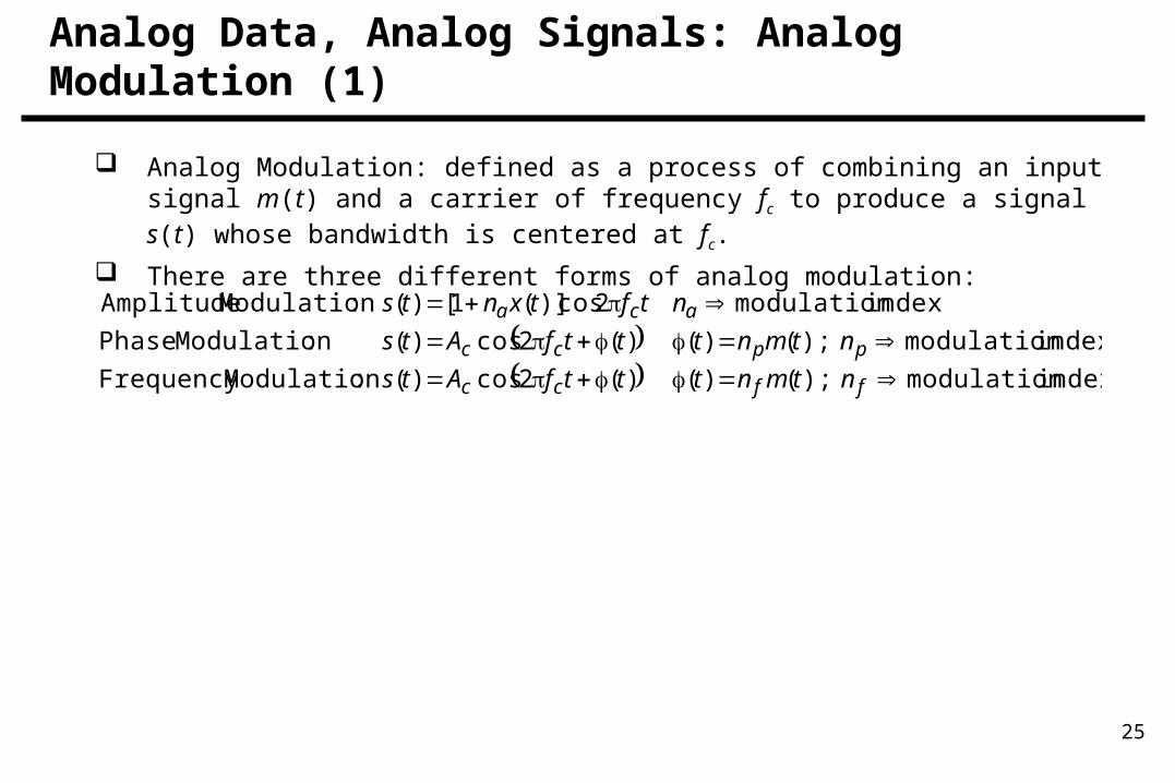
Analog Data, Analog Signals: Analog Modulation (1)
Analog Modulation: defined as a process of combining an input signal m(t) and a carrier of frequency fc to produce a signal s(t) whose bandwidth is centered at fc.
There are three different forms of analog modulation:
index modulation:ModulationFrequency
index modulation:Modulation Phase
index modulation:Modulation Amplitude
ffcc
ppcc
aca
ntmntttfAts
ntmntttfAts
ntftxnts
);()()(2cos)(
);()()(2cos)(
2cos)](1[)(

26
Comparison (2)

27
Bandwidth of Analog Modulation Schemes (3)
In terms of Bandwidth, FM and PM requires higher bandwidth than AM.
Baseband versus Broadband Schemes:Baseband do not modulate the frequency of the information signals. e.g., Line codes, PCM / Delta modulation.Broadband shift the frequency of the information signals to a higher frequency. e.g., FSK/PSK/ASK (digital modulation schemes) or AM/PM/FM (analog modulation schemes).
)(2
)1(2
2
tsA
nAn
BB
BB
m
f
mp
T
T
of value maximum the is and
FM for
PM forwhere
:FM / PM
:AM