corrosion management solutions
TRANSCRIPT

CORRDATA® Plus
Corrosion Management Solutions
P/N 100096-Manual Rev C

P/N 100096-Manual Rev C

CORRDATA® Corrosion Monitoring System © 1991 - 2004 Rohrback Cosasco Systems Inc. All rights reserved. CORRDATA, CORROSOMETER, CORRATER, CORROTEMP and COSASCO are registered trademarks, and ICMS is a trademark of Rohrback Cosasco Systems Inc. Windows®XP, Windows®2000, Windows®98, Windows®95, and Windows NT® are registered trademarks of Microsoft Corporation. LaserJet, PaintJet, DeskJet, are registered trademarks of Hewlett-Packard Company. No part of this manual may be reproduced or transmitted in any form or by any means, electronic or mechanical, including photocopying and recording, for any purpose, without the express written permission of Rohrback Cosasco Systems Inc. ROHRBACK COSASCO SYSTEMS, INC. 11841 E. Smith Avenue Santa Fe Springs, CA 90670 Tel: (562) 949-0123 (800) 635-6898 Fax: (562) 949-3065 E-mail [email protected]

Contents Part 1 Introduction 1
What’s New 2 PC Requirements 4 Technical Support 5
Part 2 Getting Started 7 Installing CORRDATA Plus 8 Installation from a Floppy Drive 11 Installing Mate Programming Utility 12 CORRDATA Plus on a Network 13 Getting Help 15 Uninstalling CORRDATA Plus 16
Part 3 Upgrading from CORRDATA Basic Software 17 PC Requirements 18 Importing existing data files 19
Part 4 Configure a Site 21 Name a Site 22 Set Units of Measure 23 Set up Groups within a Site 24 Set up Measurement Technology 25 CORROSOMETER Specific Configuration 27 CORRATER Specific Configuration 29 Ultrasonic Specific Configuration 31 Downhole Corrosion Monitoring System (DCMS) 33 Common Configuration Items 34 Editing a Probe Configuration 36
Part 5 Configure CORRDATA Hardware 37 Normal Configuration Procedure 38 Configure Mate or UltraCorr 40 Configure RDC from Mate 42 Configure RDC direct from PC 43 Configure DCMS 44 Change a Configuration 45

Contents
Part 6 Retrieve Data 49
Transfer Data from Mate or UltraCorr 50 Transfer Data direct from RDC 57 Transfer data from DCMS tool 59 Manual Input for CORROSOMETER Systems 60 Manual Input for CORRATER Systems 64 Manual Input for Ultrasonic Systems 68 Record Events 72
Part 7 Graph Data 73 Graph Selection 74 Graph Options 77 Corrosion Rate from Metal Loss or Metal Thickness 82 Integrated Average Value of other Parameters 85 Add Annotations 87 View and Filter Plotted Data 89 Printing and Saving Graphs 91
Part 8 Printed Reports 93 Site Probe List 94 Probe Data List 95 Reconfiguration List 96 Event List 97
Part 9 Import, Export and Archive Data 99 Exporting and Archiving Data 100 Importing Data 102
Part 10 Additional Operating Notes 103 Operation on a Network 104 Importing Old CORRDATA Basic *.DAT Files 107


CORRDATA Plus 1
Part 1 Introduction
Part 1 Introduction What’s New 2 PC Requirements 4 Technical Support 5

2 CORRDATA Plus
What’s New
CORRDATA Plus is a completely new 32-bit application that has been designed specifically for the Rohrback Cosasco CORRDATA range of equipment. It may be run on Microsoft Windows XP, 2000, 98, or Windows NT. It has many features and additions over the previous software.
• Simultaneous multiple graphing of data • Up to six parameters plotted per graph • Up to four different Y-axes • Overlay of data with differing reading intervals • Simple annotation for report preparation • Automatic and Manual Data Input Capability • Standard Database for storage of data • Graph to database link for instant point identification • Data filtering and reset capability • Multiple Site capability • Printed reports for Site, probe, event log and reconfiguration data • Manage change of reading frequency, or manual to automatic in the same file record • Import data from other sites or previous CORRDATA software • Export data to other users of CORRDATA Plus or to spreadsheets
CORRDATA Plus Corrosion Management Software integrates data from the complete range of CORRDATA equipment including:

CORRDATA Remote Data Collectors (RDC's) CORRDATA Mate Data Transfer Unit CORROSOMETER Probes read by the CORRDATA Mate II Unit CORRATER Probes read by the CORRDATA Mate II Unit CORROTEMP versions of CORROSOMETER and CORRATER probes UltraCorr ultrasonic thickness measurement and data logging unit Manual CORROSOMETER Instruments (CK3 and CK4) Manual CORRATER Instruments (RCS 9000 and AquaMate) Downhole Corrosion Measurement System (DCMS) CheckMate 9030 Plus
CORRDATA Plus 3
4 CORRDATA Plus
PC Requirements The CORRDATA Plus software is a 32-bit application designed for use on Windows XP, Windows 2000, Windows 98, Windows NT 4.0 and beyond. Windows 95 is no longer supported. The PC requirements are dictated largely by the requirements for these operating systems. The minimum and recommended computer specifications are those given for the respective operating system. NOTE: Always check the Microsoft Website for the latest changes and service packs for the respective operating systems.

CORRDATA Plus 5
Technical Support For telephone support contact Rohrback Cosasco Systems at Santa Fe Springs California 1-800-635-6898, for locations where the time zone permits. Office hours in California are 7:30 AM to 4:15 PM Pacific Coast Time. For Web Site support contact Rohrback Cosasco Systems at our Webb Site at http://www.rohrbackcosasco.com. At this site you may leave e-mail messages and review the latest updates from RCS. For local area support contact your Rohrback Cosasco Systems representative in your area. You may contact him for assistance directly, or have him refer your questions back to RCS. If you are not sure of the local area contact please call or fax RCS in California for details at telephone (1) 562-949-0123, Fax (1) 562-949-3065.

6 CORRDATA Plus

CORRDATA Plus 7
Part 2 Getting Started Part 2 Getting Started
Installing CORRDATA Plus 8 Copy Protection 11 Installing Mate Programming Utility 12 CORRDATA Plus on a Network 13 Getting Help 15 Uninstalling CORRDATA Plus 16

Installing CORRDATA Plus The CORRDATA Plus software is supplied on a Compact Disk (CD). On the CD there are also subdirectories to allow a set of seven 3.5" floppy installation disks to be made if required (see later section). To commence installation on Windows XP, 2000, 98, or NT, select Settings from the Start menu and then Control Panel .
8 CORRDATA Plus
Then select the Add/Remove Programs icon. Insert the CD into the CD-ROM drive. The CD should auto-run. If it does not, browse to the CD and double click setup.exe. Use the install button to commence installation. During the installation you will be required to enter the serial number of your software. This serial number is on the front of the CD. Be sure to enter the number correctly including the CDP, with no spaces between the letters and numbers, for example.
C D P 0 1 2 3 4

When the installation of the CORRDATA Plus is complete, check which COM port you will be using for communication with the Mate I or II, UltraCorr, or direct to an RDC. The default port is one. To change this, select the Preferences menu or use the options button from the toolbar.
Then change the default port if required, and press the Save button to store the selection.
CORRDATA Plus 9
Use arrows to change the
defaas requ
ult COM port ired
A password may also be set for access to the CORRDATA Plus program in this same Preferences screen if desired. The setting up of the password is a separate operation from initiating the requirement to use the password. To set up the password press the Set Password button.

Check this box to require
password
Enter required password
in the New and Confirmation boxes
The password or change in password must be typed into the New Password box and the Confirmation box. The actual typed characters do not show on screen, so the confirmation box provides a check that the password has been correctly entered. An incorrect confirmation will not allow the password to be saved. Once the password has been set, it may be turned on and off with the Require Password check box. However, if the password has been set on and saved then the password will be required to gain access to the program. So make a note of the password in a safe place for future reference. The password box will appear after the CORRDATA Plus opening splash screen.
10 CORRDATA Plus

CORRDATA Plus 11
Installation from a Floppy Drive The CORRDATA Plus software is supplied on a CD. However, if the software is installed on a computer that only has a floppy drive, first make a set of diskettes from the CD, on a computer that has a CD and a floppy drive. The software for each floppy disk of the installation set is listed in a separate directory on the CD as disk1 for the first disk, disk 2 for the second disk and so on. Copy the contents of each of these directories to the appropriate floppy and label the floppies with the disk number. NOTE: Copy only the contents of each directory to the floppy only, and not the folder as well.

12 CORRDATA Plus
Installing Mate Programming Utility This utility is supplied with the CORRDATA Plus software as a separate program on the CD. For this installation go to the directory "Mate Programing Utility" on the CD, and run "Setup.exe". Within this directory are also sub-directories "disk1" and "disk2" that contain the files for making floppy disk installations for another computer that only has a floppy drive, if required. This utility allows the Mate or Mate II to be re-programmed should the program become corrupted. A corrupted file may be indicated by one of the following:
A Checksum Error message when the Mate is first turned on.
Large corrupted values in the display mode.
A blank screen when the Mate is turned on.
If the Mate does not communicate with the PC and the cables/connections are good. NOTE: This utility may also indicate that your Windows system is not updated as it should be to run this program. We
recommend that you accept this option to update. If you do you will need to commence the installation of the program again after the computer has been re-booted after this update.
The new Mate Programming Utility also allows the Mate or Mate II to be reconfigured as a Micromate for operation with Microcor systems. The Mate may only be programmed for one configuration or the other at one time. However the utility allows re-programming back and forth between the two configurations if necessary.

CORRDATA Plus on a Network CORRDATA Plus is not a multi-user application, but it may be used on a network. However, the data may only be written to the database by the one CORRDATA Plus application to which it is linked. However, for further information on Network Operation see Part 10, Additional Operating Notes. If data is to be viewed on another PC on the network running CORRDATA Plus software, then this must be done by the export/ import function described in Part 9 . Most commonly the CORRDATA Plus program is installed with all the data files on the local PC. When it is installed on a Network, then it is quite common to have the database file on the server, for automatic backup reasons. This is done when you Create a New Site by setting the Site Data Path to the server drive. (This drive is usually mapped to the local PC as a specific drive letter such as Y: drive)
Create a New Site
The location of the default directories for the site data files, the import/export path, and the configuration files is set in the preferences
CORRDATA Plus 13

Site files of data may be exported for use on another CORRDATA Plus program where they may be imported and added to that user's Site List.
Pathname for location of database
14 CORRDATA Plus

Getting Help Help is available in several formats
F1 Provides context sensitive help
Frequently asked question and answers are available from the icon button on the toolbar or the similar button on the opening screen of the CORRDATA Plus.
Standard Help Topics with Contents, Index, and Find capability is available from this toolbar button.
Opening Screen Question and Answer Help
CORRDATA Plus 15
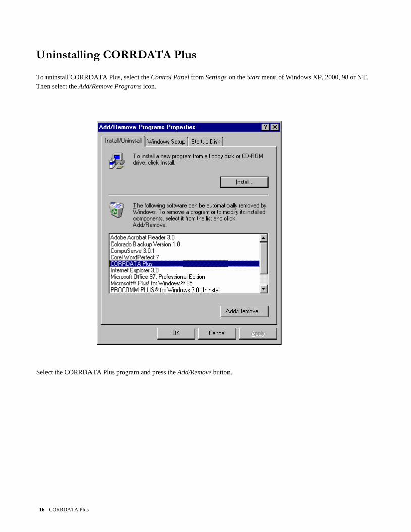
Uninstalling CORRDATA Plus To uninstall CORRDATA Plus, select the Control Panel from Settings on the Start menu of Windows XP, 2000, 98 or NT. Then select the Add/Remove Programs icon.
Select the CORRDATA Plus program and press the Add/Remove button.
16 CORRDATA Plus

CORRDATA Plus 17
Part 3 Upgrading from CORRDATA Basic Software
Part 3 Upgrading from CORRDATA Basic Software PC Requirements 18 Importing existing data files 19

18 CORRDATA Plus
PC Requirements The CORRDATA Plus software is a 32-bit application designed for use on Windows XP, 2000, 98, NT 4.0 and beyond. This program will not run under Windows 95. Hence the PC requirements are dictated by the requirements for the Windows XP, 2000, 98, and NT operating systems.

Importing Existing Data Files The import function is available in the CORRDATA Plus program to allow import of data files that have been previously collected with the CORRDATA Basic Software. To import the CORRDATA Basic software files, first create a site and a group into which the files are to be imported. See Part 4 for details. Then from the main menu select File, Import Data, or use the following icon. Select CORRDATA DOS (*.DAT).
Browse button for location of files to import
CORRDATA Plus 19

Press the Browse button as indicated to locate the CORRDATA Basic files that you need to import. These files have the form of ID__12.DAT. The files to import may be selected individually, or as a group. To select an continuous group click the first entry required and then select the last entry with the Shift key selected. To select discontinuous entries hold down the Control key while making the individual selections. This is the standard Windows selection method. Once the files have been selected, press the open button. Select the Group of your site to which you wish to import the file, and press the import button.
The selected file will be imported to the Received Data Manager. The file may be completely imported as the message indicates or the process may be repeated for the next file to be imported. The Received Data Manager allows review of the data before acceptance or rejection of this data into the CORRDATA Plus database. The Received Data Manager is described in more detail in Part 6. Access to the Received Data Manager is obtained from the following toolbar button
20 CORRDATA Plus

CORRDATA Plus 21
Part 4 Configure a Site Part 4 Configure a Site
Name a Site 22 Set Units of Measure 23 Set up Groups within a Site 24 Set up Measurement Technology 25 CORROSOMETER Specific Configuration 27 CORRATER Specific Configuration 29 Ultrasonic Specific Configuration 31 Downhole Corrosion Monitoring System (DCMS) 33 Common Configuration Items 34 Editing a Probe Configuration 36

Name a Site To configure the CORRDATA Plus program on the PC, start by selecting the large Create a New Site button from the opening screen, or from the toolbar. This will lead you through the Create a New Site configuration wizard.
Create a New Site Button
The Create a New Site wizard will prompt for the for a descriptive Site Name, and the selection for Configuring Imperial or Metric Units. The file name for the site and the directory where the site file (*.SIT) will be located will be displayed and may be amended as required before completing the wizard entries.
Check Mark shows selected
Site
Once a site has been named it will show in the Site Name box. Other Sites may be added in the same way with the Create a New Site button. To select a Site simply mouse click on the site name in the site list.
22 CORRDATA Plus

Set Units of Measure Imperial or metric units of measure are set up as part of the Create a New Site wizard, where the units of choice are selected. Once these units have been selected the data will be stored and viewed in that format. Conversion back and forth is not possible once a site is set to the required units of measure.
NOTE: If data from a PC with, say a metric site, is to be viewed on a second computer running the CORRDATA Plus
program, then a site must be set up on the second computer with corresponding units. The metric data from the first computer may be exported, and then imported into the second computer, into the metric site of that computer.
CORRDATA Plus 23

Set up Groups within a Site A Group is the next level under a Site Name. To configure a Group select Site Probe List from the Select an Existing Site screen, either from the button or from the toolbar.
This will display a site list containing any Group and Probe definitions that have been already added, ordered by Group and then by probe. A Group will normally contain all the probes that are read by a single Mate, Mate II, or UltraCorr on a single visit to the field. To add a Group use the New button in the Group box at the bottom of the screen. To edit, or remove a Group, first select the Group with the Mouse, and then use the applicable button in the Group box at the bottom of the screen.
Group Add Edit and Remove
Buttons
Selecting the New button will bring up the wizard for entering the new group name. For the Edit mode a simple text change box appears and the name is changed as required. NOTE: A group must be added to a site before any data can be imported or any new probes are added
24 CORRDATA Plus

Set Up Measurement Technology CORRDATA Plus allows a variety of measurement technologies to be monitored, including CORROSOMETER, CORRATER and Ultrasonic technologies.
Measurement Technology Selection
The recommended method of setting up the system is to configure the PC with all of the system data and then transfer the configuration to the Mate, Mate II, or UltraCorr from the PC. If required, these instruments may be configured in the field for the addition of other points, but the entry of data is not as quick as it is on a PC. Any points added in the field will automatically be added to the PC when the data is transferred to the PC. Before entering the data on the PC, first obtain the following details of all the probes: NOTE: The Mate/Mate II can be re-programmed as a Micro-Mate unit to support Microcor Technology. However Corrdata Plus software does not support Microcor. This is accomplished by a separate Microcor Software package. Contact RCS for details.
CORRDATA Plus 25

26 CORRDATA Plus
Location Tag Number Probe Model Number Probe Measurement Alloy Probe Type CORROSOMETER, CORROTEMP CORROSOMETER, CORRATER, CORROTEMP CORRATER, DCMS or Ultrasonics Probe Span on a CORROSOMETER probe Probe Multiplier on a CORRATER probe Ultrasonic Probe Type Ultrasonic Cable Type Probe Reading Interval if using an RDC Alarm Rate for Corrosion at each location for information Once all this data has been collected, you are then ready to configure the PC.

CORROSOMETER Specific Configuration
The CORROSOMETER Probe type selection has been simplified to help avoid mistakes in selecting the wrong probe type or probe span. The basic probe description of W40 Wire, T10 Cylindrical, or similar is all that is required to be selected. The probe type and span is then displayed for reference.
CORROSOMETER Probe selection Drop-down Box
If a probe to be monitored is a CORROTEMP probe, then the selection box in the wizard should be checked as shown.
CORROTEMP Probe Selection box
A CORROTEMP probe requires an appropriate instrument to be able to read temperature
CORRDATA Plus 27

If a CORROTEMP probe is selected then only instruments capable of reading temperature are available for selection. If the CORROTEMP probe is not used and the box is not checked then the longer list of instruments is available. For manual input readings select a CK3 or CK4 as applicable.
1 Units required to read CORROTEMP CORROSOMETER probes
Units that will read CORROSOMETER Probes
If an RDC of some form is selected then a selection of probe reading intervals will be displayed. The reading intervals available vary slightly according to the specific instrument.
Single Channel RDC Reading Interval Options
RDC4 Reading Interval Selection
28 CORRDATA Plus

CORRATER Specific Configuration Selection of specific information for a CORRATER probe requires the setting of the element type, either standard or flush, and the selection of the probe alloy of the electrodes. Standard electrodes are the normal 1.25" long electrodes with an area of 5 cm2 each. The flush electrodes have a surface area of 0.5 cm2 each. Electrode area directly affects the measured signal. NOTE: If a probe with different electrode areas is used the alloy multiplier must be corrected for the difference in area. The
multiplier should be modified by multiplying the standard alloy multiplier by the ratio of actual electrode area (cm 2) divided by 5 cm2. The electrode selection should still be standard.
CORRATER Electrode style and Alloy Multiplier
The selection of the Probe electrode alloy pre-selects the alloy multiplier. This is the multiplier based on theoretical calculations, which suits most common situations. If a more appropriate value has been determined (see RCS application note AN 102A), then this value may be overwritten in the multiplier value box
CORRDATA Plus 29

If a CORROTEMP probe is selected then only instruments capable of reading temperature are available for selection. If the CORROTEMP probe box is not used and is not checked then the longer list of instruments is available. For manual input readings select AquaMate or 9000 as applicable.
30 CORRDATA Plus
If an RDC of some form is selected then a selection of probe reading intervals will be displayed.
Units required to read CORROTEMP CORRATER probes
Units that will readCORRATER Probes
RDC-CA or RDC-CAT Reading Interval Selection

Ultrasonic Specific Configuration For the ultrasonic systems the basic parameters that must first be set are the type of transducer, its cable length and the alloy being monitored. The first selection in the configuration wizard gives transducer type and cable length used. Currently the UltraCorr hardware supports only the Contact type transducer.
Transducer type and Cable length Selection
Alloy Selection to set correct velocity of sound for the material
The second selection box is for the alloy to be monitored. This selection will set the velocity of sound for the selected material so that the correct thickness measurement is made. Currently the UltraCorr hardware supports the materials carbon steel, 304 and 316 stainless steel.
CORRDATA Plus 31

For ultrasonic measurements both temperature capable and non-temperature capable probes may be used. However, in both situations temperature is recorded. With a temperature capable probe this is done automatically. With a non-temperature capable probe it is set in manually for reference and later temperature correction if necessary.
An UltraCorr unit can read transducers directly and log the reading. It may also be set up as an RDC for data logging a single transducer at regular intervals. The UltraCorr setting should be used for configuration of direct probe readings. For use of the UltraCorr as an RDC, the selection of RDC -US or RDC-UST should be made. RDC-US is for data logging non-temperature transducers and RDC-UST is for logging temperature capable transducers. In the case of non-temperature capable transducers, a default temperature of 25C will be recorded. The Ultrasonic “A” Scan is for manual input readings (see Part 6). The reading interval selections for ultrasonic RDC measurements are in hours or days compared to minutes and hours for
CORROSOMETER and CORRATER probes, due to the lower sensitivity of ultrasonic measurements. More frequent readings would be unnecessary.
32 CORRDATA Plus

Downhole Corrosion Monitoring System (DCMS)
The downhole corrosion monitoring system is essentially a special type of RDC-COT, specifically designed for operation in downhole conditions. From an operational point of view, the primary differences for programming and data transfer are the communication from the DCMS tool to the Mate or Mate II is at 300 baud compared to the normal 9600 baud of a normal RDC. However, the communication from the Mate or Mate II to the PC is still the same 9600 baud. For the DCMS tool, select the collection device as DCMS. Then select the reading interval from the options available.
Select DCMS
Select required reading interval
The reading interval should be chosen so that the maximum number of readings that may be taken during the run of the tool is 1024, to avoid loss of data. At readings of once per hour, 1024 readings is 42.67 days. At a reading of once every two hours, 1024 readings is 85.33 days. This latter time is similar to the expected life of the battery. A reading of once every four hours would provide for 170.66 days, but this would be beyond the life of a standard DCMS battery.
CORRDATA Plus 33

General Configuration Items There are several items of the configuration wizard that are common to the different measurement technologies. These are location, tag number and any additional probe notes.
Global Positioning System (GPS) Co-ordinates
Probe Location
The GPS co-ordinates are useful in widely separated probe locations on a computer that has GPS capability in order to find probes and provide a unique reference
Probe Tag Number
Specific Probe Descriptive Notes
A Probe Tag Number must be entered as this is used as an automatic legend on the probe graphs. Typically a probe tag number is already
34 CORRDATA Plus

available for the probe. An additional field is available to any add any details that apply to that probe location. This provides a useful place to keep probe specific notes for future reference. Before final acceptance of the configuration a screen shows a summary of the entry.
Before final acceptance it is possible to back track through the configuration to check all the items have been correctly set. Once checked accept the configuration with the Finished button to save the configuration to the probe list. To remove a probe from the probe list, first select the probe or probes to be removed with the mouse. The selection will be indicated by the check mark to the left of the selected probes, and press the Remove button. Check Mark
Indicating selected probe/s
CORRDATA Plus 35

Editing a Probe Configuration Once a probe configuration has been saved it may be subsequently edited if required. Changing some basic parameters will require a reconfiguration of the Mate or an RDC. This sequence will be initiated automatically if one of these key parameters, shown in bold letters, is changed. This system provides the advantage of being able to change from a probe being monitored only with a Mate to one being monitored with an RDC and still keep the data in a single data file for graphing. This was not previously possible with the CORRDATA Basic software. This system also allows an RDC reading interval to be changed and still keep all the data in a single file, so that it may all be viewed on a single graph. For more details on this reconfiguration sequence see Part 5- Change a Configuration. Changes of any other parameters do not involve a reconfiguration sequence. After completion of any changes, save the new configuration with the Save button.
36 CORRDATA Plus

CORRDATA Plus 37
Part 5 Configure CORRDATA Hardware Part 5 Configure CORRDATA Hardware
Normal Configuration Procedure 38 Configure Mate or UltraCorr 40 Configure RDC from Mate 42 Configure RDC direct from PC 43 Configure DCMS 44 Change a Configuration 45

38 CORRDATA Plus
Normal Configuration Procedure The overall normal system procedure for gathering data may be summarized as follows: Setup 1. Load your IBM PC or compatible with CORRDATA Plus.
2 Attach the "Mate to PC" Cable to the appropriate serial port of the PC. 3 Configure the PC with the site, group, measurement technology, and probe information. 4 Download the configuration data from the PC to the Mate I or II, UltraCorr. 5 Configure any RDC's for continuous data collection with the Mate I or II, UltraCorr or direct from the
portable PC to RDC as applicable. 6 Leave the RDC's to collect probe data.
Data Collection
1 Plug the Mate I or II into each RDC, that is collecting probe readings and transfer the accumulated data. For the DCMS tool, collect the data with the Mate I or II after retrieval of the tool using the special interface box (see DCMS tool manual) using the 300-baud rate on the Mate I or II.
2 For a Mate II change the Mate cable and read any CORROSOMETER, or CORROTEMP CORROSOMETER probe that is not being monitored by an RDC.
3 Change the Mate II cable and read any CORRATER probe that is not being monitored by an RDC.

CORRDATA Plus 39
NOTE: CORROTEMP CORRATER probes cannot be read for temperature directly by a Mate II. Only
the corrosion rate and imbalance may be read directly from the CORRATER probe. Temperature measurement requires an RDC-CAT.
4 For an UltraCorr Unit collect all the data from the monitored points, or suspend the data logging if
collecting continuous data from one probe. 5 Attach the RDC cable to the Mate I or II and plug this into the PC adapter cable, or for an UltraCorr unit
attach the UltraCorr to PC cable. If collecting data direct from an RDC attach an RDC to PC cable. 6 Transfer all the probe data to the PC from the Mate I or II, UltraCorr, or RDC.
NOTE: CORRDATA Plus Software allows direct data retrieval from an RDC, without the need for a Mate
I or Mate II. This is permissible only in areas that are not electrically hazardous at the time of data collection since the PC is not certified intrinsically safe.
7 Select and display probe data as required.
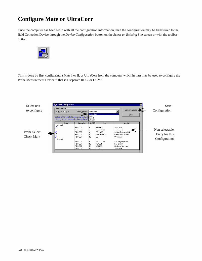
Configure Mate or UltraCorr Once the computer has been setup with all the configuration information, then the configuration may be transferred to the field Collection Device through the Device Configuration button on the Select an Existing Site screen or with the toolbar button
This is done by first configuring a Mate I or II, or UltraCorr from the computer which in turn may be used to configure the Probe Measurement Device if that is a separate RDC, or DCMS.
StartConfiguration
Select unit to configure
Probe Select Check Mark
Non selectableEntry for this
Configuration
40 CORRDATA Plus
CORRDATA Plus 41
On the Device Configuration screen, the device to be configured is selected. The probe or probes to be configured from the PC may be selected individually or as a group, by clicking the box to the left of the probe or the probe group. The selection may be toggled on and off. Any device in the probe list not compatible with the selections made will be grayed, for example an ultrasonic device will not be selectable if a Mate I is being configured. NOTE: An UltraCorr unit may also be configured as an RDC. This is not possible with a Mate I or II. For details on setting
the UltraCorr up as an RDC see the UltraCorr Manual. To prepare the Mate I or II, or UltraCorr to receive the configuration, connect the unit to the PC via the supplied cables. Switch on the Mate and press SETUP, MATE, and AUTO CONF on the Mate I or II, or PC CONF on the UltraCorr. On the PC press the Configure Device button, and then press START on the Mate to complete the transfer to the Mate. Normally a Mate configuration is set up as described and transferred from the PC. The Mate I, II, or UltraCorr may be configured in the field manually without the PC if required. To do this from the main menu press SETUP, MATE, MAN CONF and then complete the ID and configuration information as indicated. The data transferred back to the PC will not include a description or model number field. This may be done latter on the PC in the Edit Probe function

Configure RDC from Mate To configure the RDC's in the field, this is normally done from the Mate I or II as follows: Make sure to switch on the backup battery first. This is important to ensure correct operation. The location and configuration of these switches varies according to the model. (See CORRDATA System Quickstart Manual or Reference Manual for more details) Connect the main battery. Set the clock on the RDC from the Mate or Mate II, by using SETUP, RDC, ID, DATE TIME, SET. Enter the time in the format shown and press ENTER. Configure the RDC from the main menu of the Mate, or Mate II, using SETUP, RDC, ID, CONF ID, and START. When complete disconnect the Mate or Mate II and data collection will commence immediately.
42 CORRDATA Plus
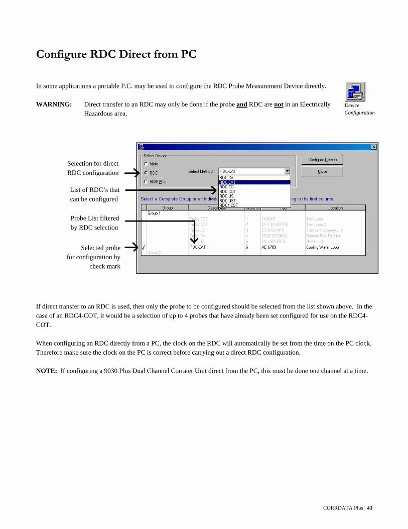
Configure RDC Direct from PC In some applications a portable P.C. may be used to configure the RDC Probe Measurement Device directly.
Device Configuration
WARNING: Direct transfer to an RDC may only be done if the probe and RDC are not in an Electrically
Hazardous area.
Selection for direct RDC configuration
List of RDC’s that can be configured
Probe List filtered by RDC selection
Selected probe for configuration by
check mark
If direct transfer to an RDC is used, then only the probe to be configured should be selected from the list shown above. In the case of an RDC4-COT, it would be a selection of up to 4 probes that have already been set configured for use on the RDC4-COT. When configuring an RDC directly from a PC, the clock on the RDC will automatically be set from the time on the PC clock. Therefore make sure the clock on the PC is correct before carrying out a direct RDC configuration. NOTE: If configuring a 9030 Plus Dual Channel Corrater Unit direct from the PC, this must be done one channel at a time.
CORRDATA Plus 43

Configure DCMS The DCMS tool must be configured through the Mate I or II. It must also be configured through an interface unit that also powers the DCMS tool during the data transfer. After transferring the DCMS probe configuration from the PC to the Mate I or II, change the baud rate on the Mate I or II to 300. To change the baud-rate switch on the Mate I or II and press READ, MODE, BAUD, and 300 to change to 300 baud. WARNING: Make sure to set the baud rate on the Mate I or II back to 9600 for communication of the Mate I or II with
the PC, otherwise data cannot be transferred. The low communication baud rate is the result of the special electronic components used for this special severe duty application. For more details on the setup of the DCMS tool see the manual supplied with the tool.
44 CORRDATA Plus

Change a Configuration The CORRDATA Plus software provides the unique ability to continue to monitor and display a continuous graph of a probe location even through changes of the monitoring instrument, probe type, or probe reading interval. This applies for changing the reading interval on an RDC, a change from a probe monitored only with a Mate to one with an RDC, or even a manually read probe from say a CK3 to an RDC. It is not possible to change between different probe measurement technologies in the continuous graph. A separate configuration is required for a different technology. To make a change in configuration select the Probe Edit button in the Probe List and make changes as required for the new configuration. If a change is made to one of the key fields highlighted in bold print then an automatic reconfiguration process will be initiated when the configuration is saved.
Key parameter change requiring new configuration
Automatic Selection of next available Unit ID
CORRDATA Plus 45

This automatic configuration not only selects a new ID for configuring the RDC, it also allows old data on the previous configuration to be collected on the old ID number, to avoid any loss of data, and then start collecting data on the new configuration. This overlap process generates the new ID called the Pending ID and the old ID becomes the Dying ID during this process.
Old Unit ID shown as
Dying
New Unit ID for new configuration shown as Pending
Once this new Pending ID has been established the Mate will need to be configured from the PC to transfer the new ID. The Mate will now contain both the Dying and Pending ID’s. When visiting the field to collect the data a Reconfiguration List may be printed out from the PC (see Part 8) to provide a reference list of any field re-configurations required and the details of the ID’s to be changed. This system is particularly useful when data is only collected at fairly long time intervals. Previously, it was not possible to change the RDC reading interval, for example, without having discontinuous probe data or data in different files. This method allows the significant amount of data on the old configuration to be collected, the unit to be re-configured, and even some data on the new configuration to be collected to bring back to the PC.
46 CORRDATA Plus

On return to the PC to transfer data the retrieval of the two sets of data and the completion of the transfer to the new configuration is completed automatically. At this point the old unit ID is available for release for future use and the change to the new unit ID is complete. WARNING: Once the transfer to the new ID is complete, the Mate memory should be cleared to complete the clearing
of the old ID from the system, otherwise the old ID may appear as a new probe on the next data transfer from the Mate to the PC.
CORRDATA Plus 47

48 CORRDATA Plus

Part 6 Retrieve Data Part 6 Retrieve Data
Transfer Data from Mate or UltraCorr 50 Transfer Data direct from RDC 57 Transfer data from DCMS tool 59 Manual Input for CORROSOMETER Systems 60 Manual Input for CORRATER Systems 64 Manual Input for Ultrasonic Systems 68 Record Events 72
CORRDATA Plus 49

Transfer Data from Mate or UltraCorr To commence transfer of data from the Mate I or II, or UltraCorr, first select Receive Data button from the Select an Existing Site screen, from the menu, or with the toolbar button.
Select Mate in the Select Device box and then select the Mate I, Mate II or UltraCorr from the drop-down box according to the device to be read.
In the Receive Data box choose the Group into which the data is to be transferred. WARNING: If you have several groups at the selected site, be careful to select the correct group into which to transfer
the data. If the wrong group is selected by mistake and the data is received, the error will normally be apparent by the messages Header Conflict in the Receive Data Manager
50 CORRDATA Plus

against all the probe entries. This is because the Tag numbers will almost certainly not match the probes in the wrong group. Select the Reject All button in the Receive Data Manager, and re-receive the data into the correct group.
The data will first go to the Receive Data Manager where it may be reviewed before acceptance into the data base. Clean data is the data from probes in the system that shows no disagreement between the
Receive Data Manager specification in the header information on the PC to that in the Mate. Normally conflicts do not occur
unless the configuration has been set up separately on the Mate and on the PC with slightly different information. The system only checks for the header information such as Tag number, probe type, probe span or multiplier, reading interval etc. It cannot check for integrity of the probe data. This may be done by reviewing the received data in the Receive Data Manager before accepting it into the data base.
CORRDATA Plus 51
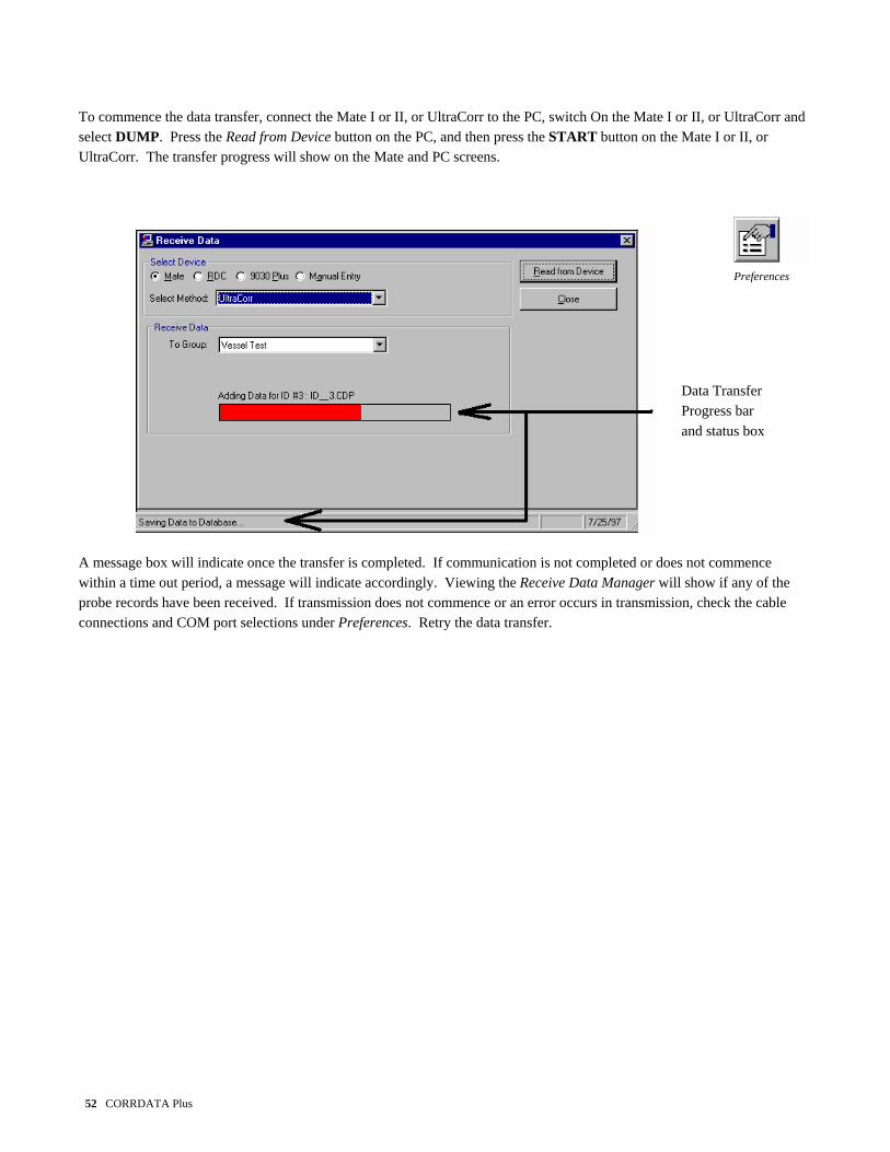
To commence the data transfer, connect the Mate I or II, or UltraCorr to the PC, switch On the Mate I or II, or UltraCorr and select DUMP. Press the Read from Device button on the PC, and then press the START button on the Mate I or II, or UltraCorr. The transfer progress will show on the Mate and PC screens.
Preferences
Data Transfer Progress bar and status box
A message box will indicate once the transfer is completed. If communication is not completed or does not commence within a time out period, a message will indicate accordingly. Viewing the Receive Data Manager will show if any of the probe records have been received. If transmission does not commence or an error occurs in transmission, check the cable connections and COM port selections under Preferences. Retry the data transfer.
52 CORRDATA Plus

On completion of the data transfer and acceptance of the message box the Receive Data Manager will appear showing the status of the received data compared to the specification of the monitored points as currently stored in the PC.
The status will be one of the following:
Clean Data The data received has header information of the key parameters that matches that already stored in the computer
Probe not defined Probe header information about a probe that is not on the PC, such as a new probe
installed in the field by configuring the set up in the Mate.
Probe Conflict The header information on the incoming data does not agree with that already in the PC. This may occur if a probe re-configuration has been made in the field on the Mate without it being initiated at the PC. The new configuration data may be accepted or rejected as appropriate.
CORRDATA Plus 53

Pending This is new data from a probe that is being re-configured through the automated sequence (see Part 5 - Change a configuration). When this probe is accepted for transfer, any associated dying configuration will be merged first as part of the merge sequence.
Dying This is data from the old configuration of a probe that is being re-configured through the
automated sequence. If this file is accepted for merging it will first be merged followed automatically by the associated pending file.
To view any of the incoming data, first select the probe, and then press the View Batch button.
54 CORRDATA Plus

To accept all of the data press the Accept All button. This will display an acceptance box before proceeding.
To accept individual entries, select that entry and press Accept Batch. This will display an slightly different acceptance box before proceeding.
Similarly any or all of the batches of data can be rejected. As the individual batches or all the batches are accepted, the entries will be transferred from the Receive Data tab list onto the Merged Data list
Merged Data Tab
List shows details of merged data
Received data tab list clears as data is merged to database
CORRDATA Plus 55

The Retrieve Data Manager may then be closed to complete the data transfer. If for any reason there are conflicts which need to be resolved, this does not have to be done before the CORRDATA Plus program is closed. If the program is closed, the current status of the data will be saved for when time is available to resolve the issues. This state will be indicated each time this site is opened with this message.
56 CORRDATA Plus

Transfer Data direct from RDC
Receive Data
In some applications a portable P.C. may be used to collect data from the RDC Probe Measurement Device directly. WARNING: Direct transfer from an RDC may only be done if the probe and RDC are not in an
Electrically Hazardous area.
Select RDC for Direct communication
Select RDC type
Select target Group for data transfer
Plug the cable for the direct PC to RDC link into the portable PC and the RDC, and press the Read Device button. WARNING: If you have several groups at the selected site, be careful to select the correct group into which to transfer
the data. If the wrong group is selected by mistake and the data is received, the error will normally be apparent by the messages Header Conflict in the Receive Data Manager against all the probe entries. This is because the Tag numbers will almost certainly not match the probes in the wrong group.
CORRDATA Plus 57

Select the Reject All button in the Receive Data Manager, and re-receive the data into the correct group. The data will first go to the Receive Data Manager where it may be reviewed before acceptance into the
Receive Data Manager
data base. Clean data is the data from probes in the system that shows no disagreement between the specification in the header information on the PC to that in the RDC. Normally conflicts do not occur unless the configuration has been set up separately on the Mate and on the PC with slightly different information. The system only checks for the header information such as Tag number, probe type, probe span or multiplier, reading interval etc. It cannot check for integrity of the probe data. This may be done by reviewing the received data in the Receive Data Manager before accepting it into the data base. If no communication occurs with the RDC and the following message appears, check the probe cable
Preferences
connection, and the COM port setting in Preferences is set correctly.
The data transfer then proceeds in the same manner as for data transfer from a Mate I or II, or an UltraCorr (see previous section).
58 CORRDATA Plus

CORRDATA Plus 59
Transfer Data from DCMS Tool Collecting data from a DCMS tool is essentially the same as collecting data from any other RDC when using a Mate I or II. The only significant difference is the communication rate between the DCMS tool and the RDC which is 300 baud compared to the 9600 baud used for the communication between a normal RDC and Mate I or II, and the Mate and PC. In addition, the DCMS tool uses a specially powered interface unit since the main battery has to be disconnected for configuration and transfer of probe data. To set the Mate I or II to the 300-baud rate, switch on the Mate and press READ, MODE, BAUD, and 300 to change to 300 baud. Plug the Mate I or II into the DCMS interface unit. Switch on the Mate I or II and press READ, and START to collect the probe data. Data collection from the DCMS tool will take 3 to 4 minutes as a result of the 300-baud rate communication. WARNING: Make sure to set the baud rate on the Mate I or II back to 9600 for communication of the Mate I or II with
the PC, otherwise data cannot be transferred. After changing back the baud rate back to 9600 baud, the data transfer from the Mate I or II is the same as the normal method described in the section Collect Data from Mate or UltraCorr earlier in this Part 6 of the manual. For more details of the DCMS tool see the manual supplied with the tool.

Manual Input for CORROSOMETER Probes
CORRDATA Plus also supports manual input readings from CORROSOMETER probes such as from a CK3 or CK4. Before entering readings it is necessary to configure the details of the probes whose data is to be plotted. To do this proceed with the configuration as described in Part 4 but select the manual instrument being used at the appropriate section of the New Probe Wizard.
Manual Reading Instruments
Once the probe specifications have been provided, the actual manual instrument readings are entered through the Receive Data button on the Open an Existing Site screen or form the Receive Data toolbar button.
Receive Data
60 CORRDATA Plus

CORRDATA Plus 61
Data Input selection for manual instrument
Selection of manual
instruments available Choose manual entry and select the instrument being used from the drop-down box. In the Receive Data box select the group in which the manual probe is located, and press the Enter Data button. A list of probes in that group that are to be read with the manual instrument selected will be shown. Manual instruments automatically have an ID allocated of 1000 or above for use by the program. NOTE: If a group is selected that does not contain a manual instrument specified then an error message will be shown. Check
that the right group or instrument has been selected, or that the probe has been configured. Error message when no
probes or instrument of the entered specification
are present
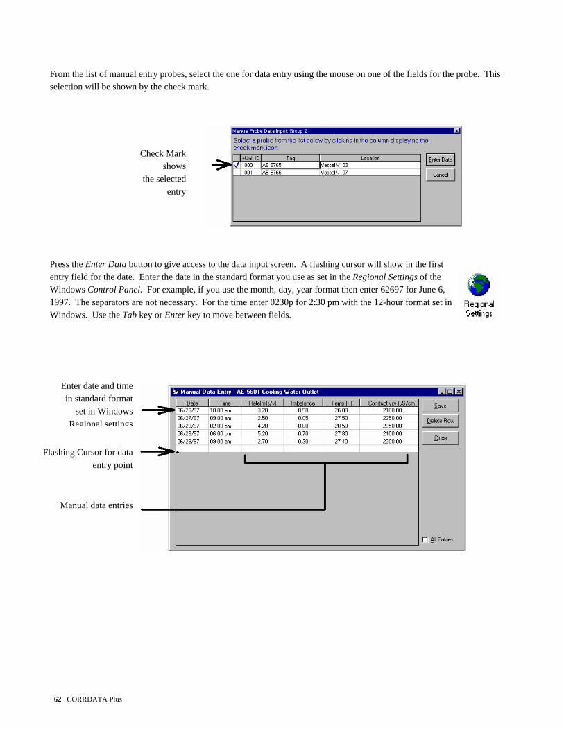
From the list of manual entry probes, select the one for data entry using the mouse on one of the fields for the probe. This selection will be shown by the check mark.
62 CORRDATA Plus
Check Mark
shows the selected
entry
Press the Enter Data button to give access to the data input screen. A flashing cursor will show in the first entry field for the date. Enter the date in the standard format you use as set in the Regional Settings of the Windows Control Panel. For example, if you use the month, day, year format then enter 62697 for June 6, 1997. The separators are not necessary. For the time enter 0230p for 2:30 pm with the 12-hour format set in Windows. Use the Tab key or Enter key to move between fields.
Manual data entries
Flashing Cursor for data entry point
Enter date and time in standard format
set in Windows Regional settings

CORRDATA Plus 63
Once all the data has been entered use the Save button to transfer the data to the database. To delete a row that has been entered incorrectly, select the row with the mouse and press the Delete Row button. This will highlight the row in red. Press Save to complete the deletion. For normal data entry only the last seven entries are shown. To show the complete list of data, check the All Entries list in the bottom right of the screen. NOTE: All Entries is slower than the normal display of seven entries, since the whole database for that probe must be
retrieved. This All Entries mode is normally only used for editing if required. In the case of CORROSOMETER probes the data entry will be in the form of divisions (where 0-1000 divisions is the linear span of the probe) which is the form of the data output from CK3 and CK4 manual instruments. Calculations to engineering units are then automatic. All other instruments will have data output in engineering units.

Manual Input for CORRATER Probes CORRDATA Plus supports manual input readings from CORRATER probes such as from a model 9000 or AquaMate. Before entering readings it is necessary to configure the details of the probes whose data is to be plotted. To do this proceed with the configuration as described in Part 4 but select the manual instrument being used at the appropriate section of the New Probe Wizard.
Manual Reading Instruments
Once the probe specifications have been provided, the actual manual instrument readings are entered through the Receive Data button on the Open an Existing Site screen or form the Receive Data toolbar button. Receive
Data
64 CORRDATA Plus

Data Input selection for manual instrument
Selection of manual instruments available
Choose manual entry and select the instrument being used from the drop-down box. In the Receive Data box select the group in which the manual probe is located, and press the Enter Data button. A list of probes in that group that are to be read with the manual instrument selected will be shown. Manual instruments automatically have an ID allocated of 1000 or above for use by the program. NOTE: If a group is selected that does not contain a manual instrument specified then an error message will be shown. Check
that the right group or instrument has been selected, or that the probe has been configured Error message when no
no probes or instrument of the entered specification
are present
CORRDATA Plus 65

From the list of manual entry probes select the one for data entry using the mouse on one of the fields for the probe. This selection will be shown by the check mark.
66 CORRDATA Plus
Check Mark shows
the selected entry
Press the Enter Data button to give access to the data input screen. A flashing cursor will show in the first entry field for the date. Enter the date in the standard format you use as set in the Regional Settings of the Windows Control Panel. For example, if you use the month, day, year format then enter 62697 for June 6, 1997. The separators are not necessary. For the time enter 0230p for 2:30 pm with the 12-hour format set in Windows. Use the Tab key or Enter key to move between fields.
Enter date and time in standard format
set in Windows Regional settings
Flashing Cursor for data
entry point
Manual data entries

CORRDATA Plus 67
Once all the data has been entered use the Save button to transfer the data to the database. To delete a row that has been entered incorrectly, select the row with the mouse and press the Delete Row button. This will highlight the row in red. Press Save to complete the deletion. For normal data entry only the last seven entries are shown. To show the complete list of data, check the All Entries list in the bottom right of the screen. NOTE: All Entries is slower than the normal display of seven entries, since the whole database for that probe must be
retrieved. This All Entries mode is normally only used for editing if required.

Manual Input for Ultrasonic Probes CORRDATA Plus supports manual input readings from Ultrasonic A Scan inspection probes. Before entering readings it is necessary to configure the details of the probes whose data is to be plotted. To do this proceed with the configuration as described in Part 4 but select the manual instrument being used at the appropriate section of the New Probe Wizard. For the screen requesting selection of a probe type enter Contact Type/0-100' cable, for a default. This field is not significant to manual inputs.
Manual Input Selection
Once the probe specifications have been provided, the actual manual instrument readings are entered through the Receive Data button on the Open an Existing Site screen or form the Receive Data toolbar button. Receive
Data
68 CORRDATA Plus

Data Input selection
for manual instrument
Selection of manual instruments available
Choose manual entry and select the instrument being used from the drop-down box. In the Receive Data box select the group in which the manual probe is located, and press the Enter Data button. A list of probes in that group that are to be read with the manual instrument selected will be shown. Manual instruments automatically have an ID allocated of 1000 or above for use by the program. NOTE: If a group is selected that does not contain a manual instrument specified then an error message will be shown. Check
that the right group or instrument has been selected, or that the probe has been configured Error message when no
no probes or instrument of the entered specification
CORRDATA Plus 69
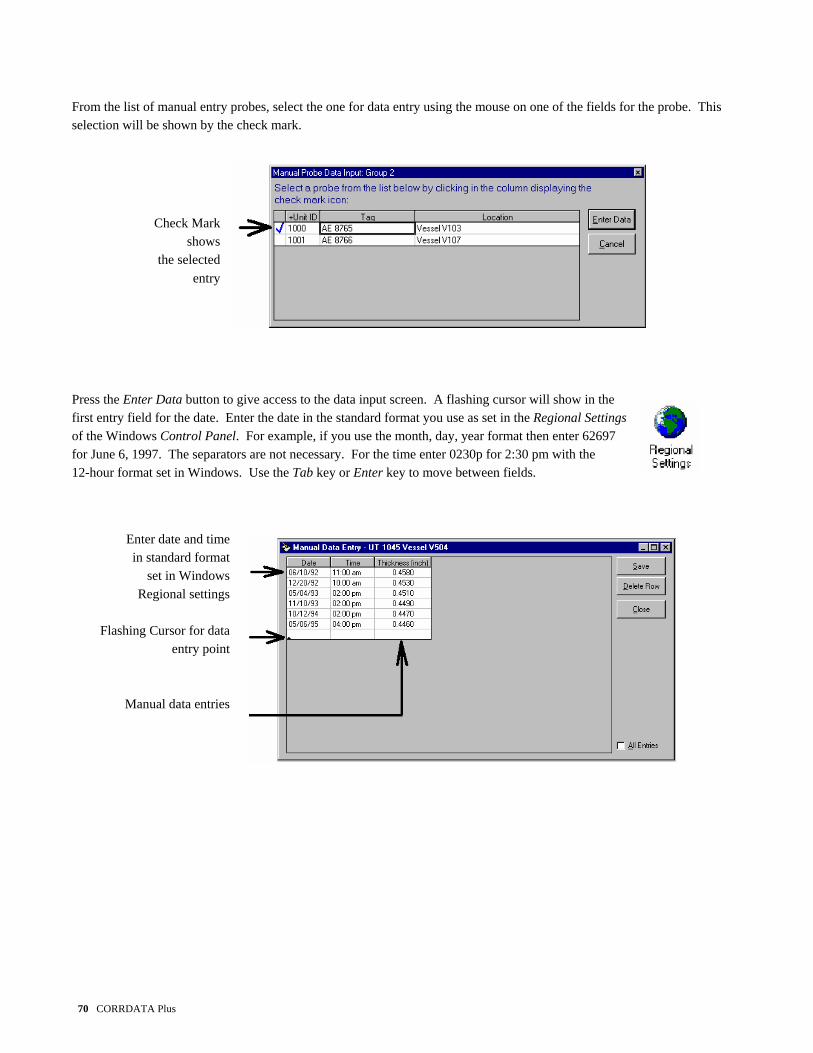
From the list of manual entry probes, select the one for data entry using the mouse on one of the fields for the probe. This selection will be shown by the check mark.
70 CORRDATA Plus
Check Mark
shows the selected
entry
Press the Enter Data button to give access to the data input screen. A flashing cursor will show in the first entry field for the date. Enter the date in the standard format you use as set in the Regional Settings of the Windows Control Panel. For example, if you use the month, day, year format then enter 62697 for June 6, 1997. The separators are not necessary. For the time enter 0230p for 2:30 pm with the 12-hour format set in Windows. Use the Tab key or Enter key to move between fields.
Enter date and time in standard format
set in Windows Regional settings
Flashing Cursor for data
entry point
Manual data entries

CORRDATA Plus 71
Once all the data has been entered use the Save button to transfer the data to the database. To delete a row that has been entered incorrectly select the row with the mouse and press the Delete Row button. This will highlight the row in red. Press Save to complete the deletion. For normal data entry only the last seven entries are shown. To show the complete list of data, check the All Entries list in the bottom right of the screen. NOTE: All Entries is slower than the normal display of seven entries, since the whole database for that probe must be
retrieved. This All Entries mode is normally only used for editing if required.

Record Events Logging of events that relate to a particular probe or a complete site can be important when later analyzing corrosion events. CORRDATA Plus enables these events to be recorded and an automatic marker
Events Log on probe graphs identifies where an item in the event log exists. Current Time Button
Site/Probe Selection
Event Description Field
Editable previous entries
To post an event, first select the probe or site from the drop-down box . The drop down box will include a list of all the tag numbers that have been configured. Enter the date and time of the event, or use the Current Time button for a current event, and then enter the details of the events in the Description box. When complete press the Post Event button to record the event to the database. Existing events can be deleted or modified as required by selecting the previous event and modifying it as required before re-saving it. Any recorded event will show up on the graphical displays as a red EV on the time axis at the time logged for the event.
72 CORRDATA Plus

CORRDATA Plus 73
Part 7 Graph Data
Part 7 Graph Data Graph Selection 74 Graph Options 77 Corrosion Rate from Metal Loss or Metal Thickness 82 Integrated Average Value of other Parameters 85 Add Annotations 87 View and Filter Plotted Data 89 Printing and Saving Graphs 91

Graph Selection
Graph and View Data
The graphing of probe data is accessed via the Graph and View Data button on the Select an Existing Site screen or by using the button on the toolbar. Selection of probes to display is by Drag and Drop with the mouse from the probe list at the bottom screen up to the graph selection box at the top of the screen
Select Probeparameter
to graph viadrop-down box
Graph Selection Box
Probe List
View table ofdata before
graphing
Any combination of probes may be selected from the probe list up to the maximum of six that can be graphed. To view the full extent of the probe list use the scroll bars to right of the list. The inner arrows scroll by one line at a time. The middle arrows scroll the extent of visible list at a time. The outer arrows move to the top or bottom of the list. Once the probes have been dragged and dropped to the graph selection box, the drop down box to the right is used to select the parameter to be plotted. If more that one parameter from a probe is to be plotted, such as metal loss and temperature, drag and drop the same probe from the list to
74 CORRDATA Plus

Separate slots on the graph selection box. The data range box normally has the All Points box checked so that all the data on the selected probes will be visible on the graph. If only a selected period of data is required, de-select this box and enter the start and end dates of the data to be viewed. The default period is three months back from the current date The Clear Settings button will cancel all the selections made from the probe list to the graph selection box. To view the graph, press the View Graph button.
The graph will be displayed with up to four y-axes if the probe selections require this. For three of four y-axes the graph will be split into an upper and lower graph each with up to two y-axes.
CORRDATA Plus 75

There are many capabilities to the graphical displays both for presentation of reports and automatic calculation of corrosion rates over selected periods. For more details see the next section Graph Options.
76 CORRDATA Plus

Graph Options Probably the first option that you will want to use on a graph will be the zoom facility.
CORRDATA Plus 77
Hold down the SHIFT key
initially while dragging a stretch
box to select window to zoom
To Zoom In hold down the Shift key initially while commencing a Drag and Drop a stretch box with the mouse to select the area to zoom. Releasing the mouse on completing the sizing of the stretch box will complete the zoom. The zoomed in area will then be viewed with a scroll bar along the bottom of the graph to move back and forth in time up to the limits of the original graph time period. To Zoom Out use the letter Z on the keyboard, or use the right mouse button to bring up the pop-up menu, and select Undo Zoom. To select a single plot on the graph to perform functions or read values from the data readout display in the upper left corner, move the mouse
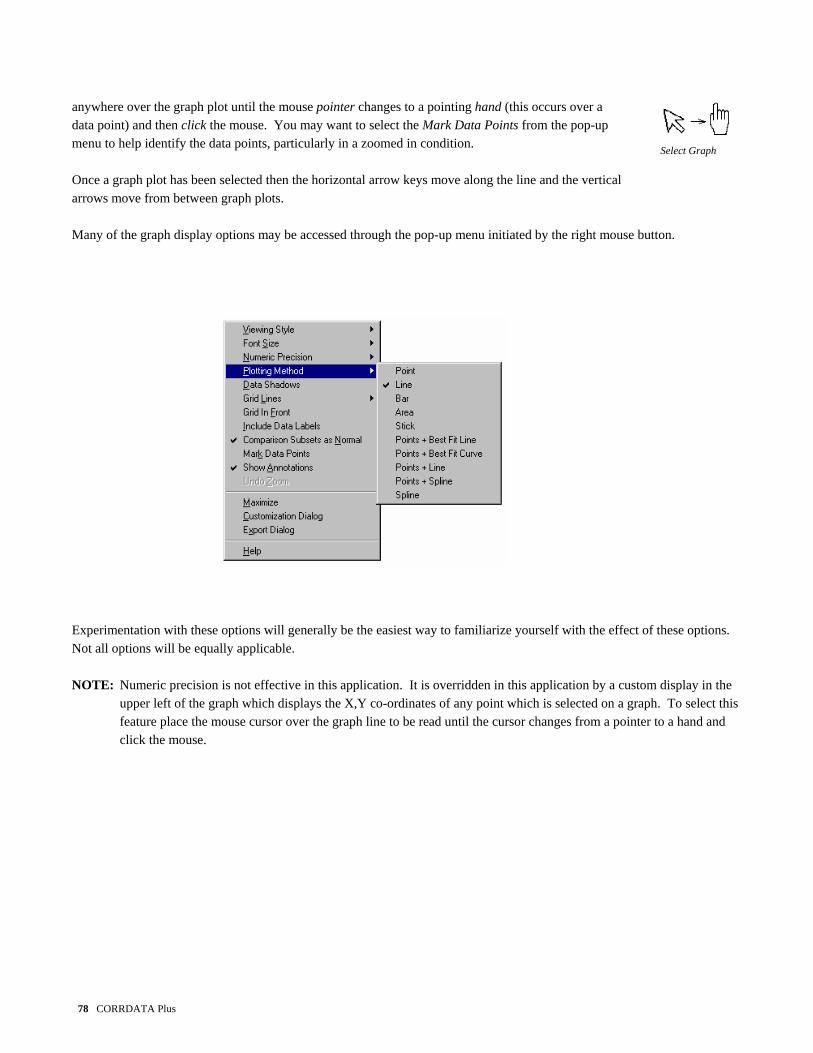
anywhere over the graph plot until the mouse pointer changes to a pointing hand (this occurs over a data point) and then click the mouse. You may want to select the Mark Data Points from the pop-up menu to help identify the data points, particularly in a zoomed in condition. Select Graph Once a graph plot has been selected then the horizontal arrow keys move along the line and the vertical arrows move from between graph plots. Many of the graph display options may be accessed through the pop-up menu initiated by the right mouse button.
Experimentation with these options will generally be the easiest way to familiarize yourself with the effect of these options. Not all options will be equally applicable. NOTE: Numeric precision is not effective in this application. It is overridden in this application by a custom display in the
upper left of the graph which displays the X,Y co-ordinates of any point which is selected on a graph. To select this feature place the mouse cursor over the graph line to be read until the cursor changes from a pointer to a hand and click the mouse.
78 CORRDATA Plus

Data labels are generally not applicable since there are so many readings on a graph that the labels tend to overwrite each other and not be readable.
On the graph, the individual plots are automatically identified by their tag number. This legend is visible on the top of the graph. If the legends are not required, for example if only one probe is graphed, and more space is desired for the graph then de-select the Show Legend box in the upper right of the graph. The customization dialog box may be accessed through the right mouse button or by Double Clicking anywhere outside the graph area of the display. This includes options for fonts, colors, titles, display of subsets etc. In addition to these customizing features there are also some specific functions to the corrosion monitoring application. These options are accessible from the Choose Function box in the lower left-hand corner of the graph.
These required functions are selected by the mouse in the list box, and controlled by the associated control box to the right of the selection list box. These functions perform the following:
CORRDATA Plus 79

80 CORRDATA Plus
Add Offset value: This adds or subtracts an offset value to the selected graph, to help separate plots that would
otherwise fall on top of each other. The amount of the offset is indicated in the legend of the selected plot.
Graph Annotation: This provides for point, x-axis, and area annotation. The annotation automatically scales with the graph zooming and attaches to the time of the point where it is entered so that it stays with the same time even if the X-axis is scrolled.
Undo Last Annotation: This enables any errors in the annotation to be undone. Point and Area annotations are treated
together for this operation. X-Axis operates separately. Run Calculations: This sets up the automatic calculation of Corrosion Rate from Metal Loss on CORROSOMETER
probes, and Integrated Average of all other parameters, such as average corrosion rate off CORRATER probes.
Set Max/Min Value: This sets the maximum and minimum Y-axis values corresponding to the graphical plot selected.
This helps scaling the graphs to better show corrosion upsets and details. CORROSOMETER probes graphs always open to the full span of the probe. All other parameters are initially auto-scaling.
Reset Graph: This resets any of the scaling and offsets that have been applied to return to the original settings.

NOTE: Always remember to select the probe graph for which these functions are to be applied before
operating the function. To do this, use the mouse to click on the graph plot. Make sure the mouse pointer turns to a hand before clicking the mouse to ensure the graph is selected. If this is difficult, such as in a zoomed in condition, first set the Mark Data Points from the pop-up menu to show the location of the actual data points.
Select Graph
CORRDATA Plus 81

Corrosion Rate from Metal Loss or Metal Thickness
With CORROSOMETER probes the graph shows a plot of metal loss against time. With an Ultrasonic probe the graph shows a plot of metal thickness against time. In both cases, zero corrosion rate corresponds to a horizontal line. On a CORROSOMETER probe, the steeper the upturn of the graph the greater the corrosion rate. On an Ultrasonic probe the steeper the downturn the greater is the corrosion rate. To calculate corrosion rate from metal loss over any portion of the graph is necessary to calculate the slope over this portion. This is done automatically in CORRDATA Plus by simply selecting the portion of the graph over which the rate needs to be calculated. On this example it is clear that the corrosion rate was low at first, but then at about mid-day on Mar 23rd there was a substantial corrosion upset.
Select Start and End point with
mouse and press Run Button to Compute Rate
Calculated
Corrosion Rate of 4.19 mpy
82 CORRDATA Plus

To calculate corrosion rate from metal loss, first select Run Calculations from the Choose Function list box. Then with the mouse select the point on the graph where to calculation is to start and then the point where it is to end. Remember that a point on the graph can be selected when the mouse pointer turns to a pointing hand. Press the Run button for the computation of corrosion rate by the method of linear regression through the selected points. To repeat the calculation, such as through the corrosion upset shown, simply select another start and end point and press the Run button again.
Select Graph
CORRDATA Plus 83
New Start and End Point
New Corrosion Rate
of 205.89 mpy
This sequence may be repeated as often as required.

With an Ultrasonic probe the principle is the same but the graph will trend downward as it corrodes since it is metal thickness, whereas with a CORROSOMETER probe the graph will trend upwards as it corrodes. In either case this is handled automatically by the software.
84 CORRDATA Plus

Integrated Averaged Value of Other Parameters
For all other parameters than metal loss and metal thickness, the Run Calculations function computes the integrated average value of the parameter. The integrated average value rather than just the average value is important, especially when the readings may be taken infrequently instead of at regular intervals. For example, suppose a manual instrument read a CORRATER probe over a one-month period, so that the first three readings were once per week, and then on the last week the readings were taken every day. Let’s also suppose the rate for the first 3 weeks was 1 mpy for each reading, but in the last week, due to an upset, the readings were all 10 mpy. The normal average would be 7.3 mpy even though the rate was only 1 mpy for three of those four weeks. The true average or integrated average would be the effect of three weeks at 1 mpy and one week at 10 mpy would be 3.25 mpy. The integrated average computes the area under the graph and divides it by the time to give a true average value.
Selected period for Calculation
Integrated Average
Corrosion Rate
CORRDATA Plus 85

To calculate the integrated average corrosion rate in this case, first select Run Calculations from the Choose Function list box. Then with the mouse select the point on the graph where to calculation is to start and then the point where it is to end. Remember that a point on the graph can be selected when the mouse pointer turns to a pointing hand. Press the Run button for the computation of integrated average corrosion rate. Select Graph
86 CORRDATA Plus

Add Annotations The ability to add annotations to graphs easily is important in preparing reports. Usually it is difficult when using spread sheets because any annotations don’t move with the data to which they are related. CORRDATA Plus enables annotations to be made which move with the data, or move along with time even when the graphs are zoomed or scrolled in time.
Area Annotation Point Annotation X-axis Notation
To remove an annotation select Undo Last Annotation from the Choose Function box and select the type of annotation to be removed, either X-axis or Point/Area (Point and Area act together for this function). Press Run to successively remove the annotations.
CORRDATA Plus 87

The same annotations shows up in a proportional size even with multiple zoom ns as shown.
Automatic event markers show as an EV on the X-axis at the appropriate time point. These can be removed if required with the Undo Last Annotation. The details of the event must be added manually since they cannot be transferred from the event log directly.
88 CORRDATA Plus

View and Filter Plotted Data Data may be filtered or bad points cleared extremely easily with CORRDATA Plus. Normally with spreadsheets it is easy to see a bad point visually on a graph but it is much more difficult to find it in the data. With CORRDATA Plus simply point to the data on the graph and then press the View Data button to take you directly to the value in the data base.
Remove the same point from the graph if required with the Exclude Pts button. This will convert the reading to -99999.000, which the same as a “no data” point. Alternatively, a more reasonable value may be overwritten. The new points are held in the file for future viewing of the graph. The original data points are never lost but are always stored in the data base for retrieval with the Reset button in the View Data screen. Multiple selection of points can be made in the usual Windows fashion of holding down the Shift key
CORRDATA Plus 89

while selecting the first and last in the list to be selected, or holding down the Control key to select individual entries. To make the selection use the gray cells to the left of the displayed values.
90 CORRDATA Plus

Printing and Saving Graphs Completed graphs may be saved in Metafile or Bitmap format for later use in written reports.
The graphs may be sent to the Clipboard for direct Cut and Paste to your report writing program, directly to the printer, or saved to a file for future use. The size of the graph may be left as is, or adjusted to any specific size if required before exporting the graph.
CORRDATA Plus 91

92 CORRDATA Plus

Part 8 Printed Reports Part 8 Printed Reports
Site Probe List 94 Probe Data List 95 Reconfiguration List 96 Event List 97
CORRDATA Plus 93

Site Probe List
Site ReportsThere several printed report formats that are available accessed from the Site Reports button on the Select an Existing Site screen or from the toolbar button The probe list is a listing of all the probes on the selected site as seen on the Site probe list. First select Probe List from the drop-down Report list box. For the probe list there are not further selections. Press the Preview button to see the details of the listing before printing.
Press Preview to show listing before
printing
Select Site Probe List from Report
drop-down list
To print the probe list from another probe, go to the Select an Existing Site screen and select the site required.
94 CORRDATA Plus

Probe Data List The preparation of the Probe Data List is similar to that for the Site Probe List except that the individual probe must be selected from the list of Tag numbers in the Unit list box. First select Probe Data List from the Report drop-down list box, and then select the probe by its Tag from the Unit drop-down list box. Select the time period of the data required. The default is the last seven days. Alternatively, the complete data list may be selected by checking the All Entries box.
All entries check box Time period
selection
Tag Number Probe Selection
Press the Preview button to display the data, and the Print button to produce the printed report.
CORRDATA Plus 95

Reconfiguration List The reconfiguration list provides a listing of any probe or RDC’s that has been selected for reconfiguration due to a change of probe type, RDC reading interval or similar event requiring reconfiguration. This report is to simplify details on the change of Unit ID’s for the operator in the field.
Existing ID for data collection and then to be reconfigured New configuration ID to be used Probe Tag Number
The reconfiguration list is similar to the Site Probe list in that there is only one list per site. Select the Reconfiguration List from the drop-down Report box. Press the Preview button to see the list and press the Print button for a printout.
96 CORRDATA Plus

Event List Any events that have been logged can also be printed out. The Event list is similar to the Site Probe list in that there is only one list per site. Select the Event List from the drop-down Report box. Press the Preview button to see the list and press the Print button for a printout. The event list is similar to the Probe Data list in that the period of data can be selected. The default time period is the last seven days. Alternatively, the complete data list may be selected by checking the All Entries box.
CORRDATA Plus 97

98 CORRDATA Plus

Part 9 Import, Export and Archive Data Part 9 Import, Export and Archive Data
Exporting and Archiving Data 100 Importing Data 102
CORRDATA Plus 99

Exporting Data Data collected with CORRDATA Plus on one computer may be transferred to a another computer for viewing under CORRDATA Plus on that computer. The data is stored by site in an *.SIT file in the CORRDATA Plus directory. An exported file can include some or all of the probes in that site. This may be useful for sending via diskette, over the network, or E-mailing to a remote location for review by someone else. An exported file has the date and time of export added to the name and its extension is changed to *.SIX to distinguish it from a normal site file.
Export Data
The data may also be exported in a Comma Separated Variables (CSV) format for importing or opening into a spreadsheets such as Lotus or Excel.
CORRDATA or Spreadsheet Format Browse button for Exported File destination
Data Selected for Export When the data is exported, the original data remains intact, so the exporting is a “copying” function. The Export feature may also be used to generate archive files for historical purposes. At the same time as the file is exported to the archive location, the existing data file may cleared of old data so
100 CORRDATA Plus

that the files to not become too large and filled with data that is not required. To complete the purging of the existing file when generating the archives select the Purge Data following Export, and select the date to which the data is to be purged. By default the time selected is twelve months prior to the current date. This may be changed as required
Data is purged out if it preceded this date, to leave data from this date to the present date
Check this box to purge out old data The exported file has the date and time added to the title so that successive exports of the same site may be easily identified. When these files are imported they will then remain separate, and old files may then be deleted as required.
CORRDATA Plus 101

Importing Data
Import Data
To import data generated by a second CORRDATA Plus application on another computer, it is first necessary to export the file from the other computer (see previous section). The exported file may then be imported and added to the list of sites on the first computer. Select the Import Data button.
Check to import CORRDATA Site File Browse button to locate file to import Default directory for imported file
Check the box for importing a CORRDATA Plus site file (*.SIX), browse for the file to be imported. The import directory will be the directory in which the site files reside. This will normally be the CORRDATA Plus directory, and is set in Preferences. Select Import to complete the operation. Once the import is complete, the imported site name will appear in the Site probe list. NOTE: If the same site information is imported at a latter date with more up-to-date information. Both versions will then
appear on the site list but with different dating. The oldest site may then be removed if required.
102 CORRDATA Plus
Part 10 Additional Operating Notes Part 10 Additional Operating Notes
Operation on a Network 104 Importing Old CORRDATA Basic *.DAT Files 107
CORRDATA Plus 103

Operation on a Network The CORRDATA Plus program is not designed as a client/server application but it may be operated on a Network with some minor limitations. The data base may be read by multiple PC∗s, but the basic configuration file CORRDATA.CFG and any of the Site files (*.SIT) may only be written to by one PC at any one time. This is usually not a problem since the configuration is first installed, or later changed, from one PC at a time. Similarly data input is usually only done from one PC at a time to the same site file. When the CORRDATA Plus program is installed, the location of the master configuration file, CORRDATA.CFG, is recorded in the Microsoft Registry. During installation of the CORRDATA Plus, this master file is installed on the local hard disk on the drive where the CORRDATA Plus program is installed. Inside this CORRDATA.CFG file, the location of the Site Files (*.SIT) are stored. When CORRDATA Plus is used on a Network, it is necessary to move the CORRDATA.CFG configuration file (and the Samp1.SIT file) to the shared network location, and to indicate this location in the Registry of each PC running the CORRDATA Plus software. It is then necessary to indicate the new location of the files in the Registry. NOTE: If the CORRDATA Plus program has already been used on a single PC and data has been collected, then
transferring to operation on a network also requires transfer of all of the Site Files (*.SIT) and the CORRDATA.CFG to the shared network location.
104 CORRDATA Plus

Install the CORRDATA Plus program and security key as normal, and set the COM port as required. Exit the program. In Microsoft Explorer move the Samp1.SIT file and the CORRDATA.CFG file from the CORRDATA directory where it is installed to the shared directory on the server that is to be used for the database. From the Start menu select Run and type Regedit and OK. Warning: This gives access to the Registry of the computer. Any errors in the changes made can cause problems in
the operation of the computer. It is advisable to make a copy of the registry before proceeding so that it may be restored if problems occur. To make a copy of the registry go to Registry and Export Registry File. Save this file to a temporary directory on the hard drive. It is too large for a floppy drive. Also note that changes made in the registry are effective immediately. You cannot keep the previous version by not saving the change, since there is not a separate Save sequence in the registry.
Select HKEY_CURRENT_USER, Then Software Then VB and VBA Programs Settings Then CORRDATA Then Default Double-click on SYSDB and enter the full pathname of the CORRDATA.CFG file on the shared directory of the server. This should be entered in the form:
\\server name\data directory\CORRDATA.CFG for example:
\\ntserver\corrosion data\corrdata.cfg
CORRDATA Plus 105

In cases where the server is mapped to a drive letter on the local PC, then enter:
Mapped Drive Letter \data directory\CORRDATA.CFG For example,
Z:\corrosion data\CORRDATA.cfg Close the Registry Start the CORRDATA Plus program and select the Options button on the toolbar. The Configuration Data should now should the shared Network directory location of the CORRDATA.CFG file
Change the Site Data and the Import/Export Path to show the Network directory where the Samp1.SIT file is located. This will ensure that the default directory for any new sites, imported or exported data, will be in the same Network directory, otherwise these new sites will not be available to the other PC’s. For each of the other PC∗s on the system using the CORRDATA Plus software, install the software and security key on each of the PC∗s, and repeat the above procedure of changes to their Registry, and the changes in the Options menu of the CORRDATA Plus program. It is not necessary to move the files as done on the first PC, since the necessary common files will already be in the shared Network location.
106 CORRDATA Plus

All of the PC’s should then be accessing the configuration file and the same database. From one of the PC∗s enter all of the site and probe configuration data. The Mate or Mate II's may be configured and the data retrieved from any of the PC's running the CORRDATA Plus program. NOTE: Data may be read from any PC. However, if data is being viewed at one computer while probes or sites are being
added at a second computer, then the newly added sites and probes will not be visible on the first computer, until the program is closed and restarted. On graphical displays, changes in the graphed data (such as edited points) will be available as soon as the graph mode is exited and re-entered without leaving the CORRDATA Plus program.
WARNING: Removing a site from one PC will cause problems on other PC∗s if they are set to the site that has been
deleted. To prevent this happening it is recommended that one site such as the Sample Site not be deleted. This file is not used for data but just as common site for all the PC∗s. This site should then be selected before exiting the program and avoids the above problem.
CORRDATA Plus 107