corrosion inhibiting engine oils · corrosion inhibiting engine oils: dtic elece ioct ... project...
TRANSCRIPT
',. CORROSION INHIBITING ENGINE OILS
DTIC: ELECE
IOCT 2 7 1981
Pratt & Whitney Aircraft Group
Government Products Division EWest Palm Beach, Florida 33402
August 1981
Interim Report for Period 4 September 1979 - 1 December 1980
CApproved for Public Release; Distribution Unlimited
LjU
_ _MATERIALS LABORATORYAIR FORCE WRIGHT AERONAUTICAL LABORATORIESAIR FORCE SYSTEMS COMMANDWRIGHT-PATTERSON AIR FORCE BASE, OHIO 45433
81 10 26 054
NOTICE
o en Government drawings, specifications, or other data are used
for any purpose other than in connection with a definitely relatedGovernment procurement operation, the United States Government thereby
incurs no responsibility nor any obligation whatsoever; and the fact
that the government may have formulated, furnished, or in any way
supplied the said drawings, specifications, or other data, is not to
be regarded by implication or otherwise as in any manner licensing the
holder or any other person or corporation, or conveying any rights or
permission to manufacture, use, or sell any patented invention that
may in any way be related thereto.
This report has been reviewed by the Office of Public Affairs(ASD/PA) and is releasable to the National Technical InformationService (NTIS). At NTIS, it will be available to the general public,
including foreign nations.
This technical report has been reviewed and is approved for
publication.
WAYNE k. WARD, Project En ineer B. D. McCONNELL, ChiefFluids, Lubricants, and Elastomers Branch
FO H IRECTOR:
F. D. CHERRY, Chief
Nonmetallic Materials Vision
"If your address has changed, if you wish to be removed from our
mailing list, or if the addressee is no longer employed by your
organization please notify AFWAL/MLBT , WPAFB, OH 45433 to help
us maintain a current mailing list".
Copies of this report should not be returned unless return is required
by security considerations, contractual obligations, or notice on aspecific document.
AIR FORCE/56780/20 October 1981 - 280
SECURITY CLASSIFICATIONt OF TH.IS PAGE (When Deata~e.d
> ANWAL R-81-4 284TITLE (la Subtitle)
z
CO~RROSION INHIBTN ENGINE -FR-390 OR. REOT NU
DCONTRC OR GRANT NUMBER(s)
.C.rownR. J.Meehn /C F33615--79-C-50891 r
ORM... OR.ANIZATION NAME AND ADDRESS 10- PROGRAM ELEMENT. PROJECT. TASK~Pratt & Whitney Aircraft Group AREA & WORK UNIT NUMBERS
Government Products Division 25: '..71Rj
P.O. Box 2691, West Palm Beach, Florida 33402
It. CONTROLLING OFFICE NAME AND A1DDRESS n*,
Air Force Wright Aeronautical Laboratories, AFSCq ". NUMBER OFPAGESWright-Patterson Air Force Base, Ohio 45433 73
14. MONITORING AGENCY NAME & AOG.RESS(it differe"( fre. Controlling Offic.) IS. SECURITY CLASS. (o1 this report)
I;> ~ ~ Unclassified
ISs. DECL ASSIFI CATION/ DOWNGRADINGSCHEDULE
16. DISTRIBUTION STATEMENT (of chi. Report)
Approved for public release; distribution unlimited.
17. DISTRIBUTION STATEMENT (*I the abstract entered in Block 20, It different from, R.pert)
IS. SUPPLEMrNTARY NOTES
19. KEY WORDS (Continuee an reverse side it necessary and Identify by block numbe,
Oil corrosion inhibitor Corrosion testCorrosion analysis Turbine engine lubricantCorrosion inhibitor analysis Corrosion inhibiting lubricant
20. ABSTRACT (Coentinute en reverse side if necessary and identify by block. num.ber)
XThe Fluids, Lubricants, and Elastomers Branch of the MaterialsLaboratory,fAir Force Wright--*A9ro-fatieel1 Labev44ov-i4 s established therequirement's for a MIL-L-7808H operational oil with corrosion inhibitioncharacteristics at least equal to those of MIL-C-8188C. The new oilformulation is to provide corrosion inhibition under long-term storageconditions of the ALCM F107 turbine engine. During the initialfifteen-month effort, several approaches were evaluated as candidate
Lmethods for determining the effectiveness of corrosion inhibiting oil -
DD I JA 7 1413 EDITION OF I NOV 65 IS OBSOLETE
SECURITY CLASSIFICATION OF TIlS PAGE (Whe n Data Ente.eeiI
00 r'
SECURITY CLASSIFICATION or THIS PAGE(Wh.J Dote Entered)
20. ABSTRACT (Continued)
ladditives. A screening procedure was developed after preliminary
modifications were made to the Corrosion Rate Evalu~tion Procedure
(CREP). Using the CREP together with compatibility and miscibility
screening of oil/inhibitor blends, a total of 67 candidate corrosion
inhibitors (CCi) were evaluated. These included CCI obtained from Bray
Oil Company, El Monte, California, as part of a subcontract to synthesize
candidate corrosion inhibitors. Additional tests were completed on a
preliminary physical and chemical property evaluation of the oil/-
inhibitor blends in regard to MIL-L-7808H and MIL-C-8188C specifications.-
fccession For
YTIS GRAH&IDTIC TAB ElUnannounced ElJuj,"t if ieat ion
Distribution/
Availability CodesjAvail and/or
Dist Special
IOD
! SrCUirTY CLASSIFICATON OF THIS PAG (W e 't Eted)
FOREWORD
This report describes the technical effort conducted by theAdvanced Fuels and Lubricants Group of United Technologies Corpora-
tion, Pratt & Whitney Aircraft Group, Government Products Divisionunder Contract F33615-79-C-5089, Project ILIR, Task 01, Work Unit 25,Corrosion Inhibiting Engine Oils. This program is under the directionof Dr. Wayne E. Ward of the Fluids, Lubricants, and Elastomers Branchof the Materials Laboratory, Air Force Wright AeronauticalLaboratories, Wright-Patterson Air Force Base, Ohio.
The technical effort disclosed herein was performed during theperiod 4 September 1979 to I December 1980 under the direction of thePratt & Whitney Aircraft Group Program Manager, Mr. Grayson C. Brown.
The report was released by the authors in March 1981.
This report is an interim Report concerned with the development
and laboratory analysis of corrosion inhibiting additives for use withcurrent MIL-L-7808H type lubricating oils. The final formulation isto provide corrosion protection under long-term storage conditions andbe an operational lubricant in the Williams Research Company FI07 tur-bine engine. A Final Report will follow at the conclusion of thetechnical effort.
ACKNOWLEDGEMENTS
The candidate corrosion inhibitors evaluated in this program wereacquired through the cooperation of the manufacturers listed below:
Bray Oil Company Nalco Chemical Company
9550 Flair Drive Petroleum Chemicals DivisionSuite 301 Sugarland TX 77478El Monte CA 91731
Edwin Cooper Incorporated Pfaltz & Bauer Incorporated
Subsidiary of Ethyl Corp. 375 Fairfield AvenueRoute 3 Stamford CT 06902Sauget IL 62201
E. I. DuPont & Co., Inc. Ronco Laboratories Incorporated
Petroleum Chemicals Division 3617 Brownsville RoadWilmington DE 19898 Pittsburg PA 15227
Minnesota Mining & Mfg. Co. The Lubrizol Corporation3M Center 19400 Lakeland BlvdSt. Paul MN 55101 Wickliffe OH 44092
Mooney Chemicals Incorporated Universal Oil Products Company2301 Scranton Road UOP Process DivisionCleveland OH 44113 Des Plaines IL 60016
iii
TABLE OF CONTENTS
SECTION PAGE
I INTRODUCTION 1
II TASK 4.1 - LITERATURE SEARCH AND CUSTOM SYNTHESIS 3
III TASK 4.2 - TEST PROCEDURE DEVELOPMENT AND VALIDATION 7
IV TASK 4.3 - FORMULATION AND EVALUATION OF CORROSIONINHIBITING ENGINE OILS 25
V CONCLUSIONS 59
VI RECOMMENDATIONS 61
APPENDIX A CORROSION RATE EVALUATION PROCEDURE (CREP)
FOR THE GRAVIMETRIC DETERMINATION OFCORROSION RATES OF ENGINE HARDWARE WITHJET ENGINE LUBRICANTS 63
APPENDIX B A TRUNCATED SEQUENTIAL SAMPLING PLAN FOROIL ADDITIVE MIL-C-8188C COMPARISON STUDY 71
REFERENCES 72
...I I . ... . i 1 .i m ni" ln .. . .. .. .° . .... . . .
LIST OF ILLUSTRATIONS
FIGURE PAGE
I Miscibility/Corrosion Rate Test Results AfterScreening 67 Candidate Corrosion Inhibitors (CCI)With the P&WA/GPD Developed Corrosion RateEvaluation Procedure (CREP) 46
A-I Dual Reaction Chamber With Peripheral Equipment 67
A-2 Reaction Chamber With Sample Strips 68
vi
LIST OF TABLES
TABLE PAGE
1 Time/Temperature Equilibrium Study of Parr Bomb Used
for Oxygen-Rich Corrosion Test 10
2 Oxygen-Rich Pressurized Corrosion Testing 11
3 Corrosion Protection Comparison of Time in HumidityCabinet and Centrifuge Time 17
4 ASTM B-117 Salt Spray Corrosion Evaluation -A Comparison of Salt Spray Time and Centrifuge Time 19
5 Effects of One Hour Salt Spray Corrosion TestingUsing 1.0% Additive/MIL-L-7808H Oil Mixtures 21
6 Corrosion Rate Tests Conducted to Determine theRepeatability of the Corrosion Rate EvaluationProcedure 22
7 A General Description of the Active Ingredient ofEach Candidate Corrosion Inhibitor 26
8 Data From the Corrosion Rate Evaluation Procedurefor Candidate Corrosion Inhibitors (CCI) at 1.0 w/oin Mobil MIL-L-7808H, QRN 15F-1 29
9 Solubility Characteristics of the Candidate CorrosionInhibitors at 2.0 w/o Active Ingredient in MobilMIL-L-7808H, QRN 15F-1 33
10 Solubility Characteristics of the Candidate Corrosion
Inhibitors (Previously Rejected at Maximum Concentra-tion) at 0.5 w/o Active Ingredient in MobilMIL-L-7808H, QRN 15F-1 35
II Data From the Corrosion Rate Evaluation Procedure forCandidate Corrosion Inhibitors (CCI) at 2.0 w/o ActiveIngredient (AI) in Mobil MIL-L-7808H, QRN 15F-I 39
12 Data From the Corrosion Rate Evaluation Procedure forCandidate Corrosion Inhibitors (CCI) at 0.5 w/o ActiveIngredient (AI) in Mobil MIL-L-7808H, QRN 15F-1
13 Key to the Superscript Notation of Figure 1, Listing
the Candidate Corrosion Inhibitors (CCI) Accepted orRejected at Each Phase of the Screening Test Series 47
vii
LIST OF TABLES - Concluded
TABLE PAGE
14 Data From the Corrosion Rate Evaluation Procedure forthe Most Promising Candidate Corrosion Inhibitors (CCI)at 2.0 w/o Active Ingredient (AI) in Mobil MIL-L-7808H,QRN 15F-l 48
15 Data From the Corrosion Rate Evaluation Procedure forthe Most Promising Candidate Corrosion Inhibitors (CCI)at Various Concentrations in Mobil MIL-L-7808H, 51QRN 15F-1
16 Properties of the Most Promising Candidate Corrosion 5Inhibitor (CCI)/MIL-L-7808H Formulations
17 The Effect of 2.0 w/o Active Ingredient (AI) ofCandidate Corrosion Inhibitors (CCI) on the Colorof MIL-L-7808H, QRN 15F-I, and the Extent ofSedimentation After Five Months Storage
B-I Sequential Sampling Plan, With an Alpha of 0.05 and
a Beta of 0.37 71
vi
II
vf Ii
LIST OF ABBREVIATIONS
AFWAL Air Force Wright Aeronautical LaboratoriesAI Active ingredientALCM Air-launched cruise missileAQL Acceptable Quality Levelatm AtmospheresASTM American Society of Testing and Materialscc/min Cubic centimeters per minuteCCI Candidate corrosion inhibitorscm CentimetersCOS Corrosion Oxidation StabilityCR Corrosion rateCREP Corrosion Rate Evaluation ProcedurecSt CentistokesDI Deionized (water)dia DiameterFTM Federal Test Methodg Gramshr Hours
in. Inchesmg Milligramsmin Minutesml MillilitersMLBT Fluids, Lubricants and Elastomers Branch, Materials
Laboratory, AFWALmm Millimeters
MN/m2 Meganewtons per square meterN Number of corrosion rate determinationsNBS National Bureau of StandardspH Hydrogen ion concentrationPMC Product Material ControlP&WA/GPD Pratt & Whitney Aircraft, Government Products DivisionQPL Qualified Products ListQRN Quality Reference Numberrcf Relative centrifugal forceRQL Rejectable Quality Level
sec SecondsSEM Scanning electron microscopySSP Sequential Sampling PlanTStandard taperTAN Total acid numberUTC United Technologies Corporation
v/o Volume percentw/o Weight percentWPAFB Wright-Patterson Air Force Base
ix
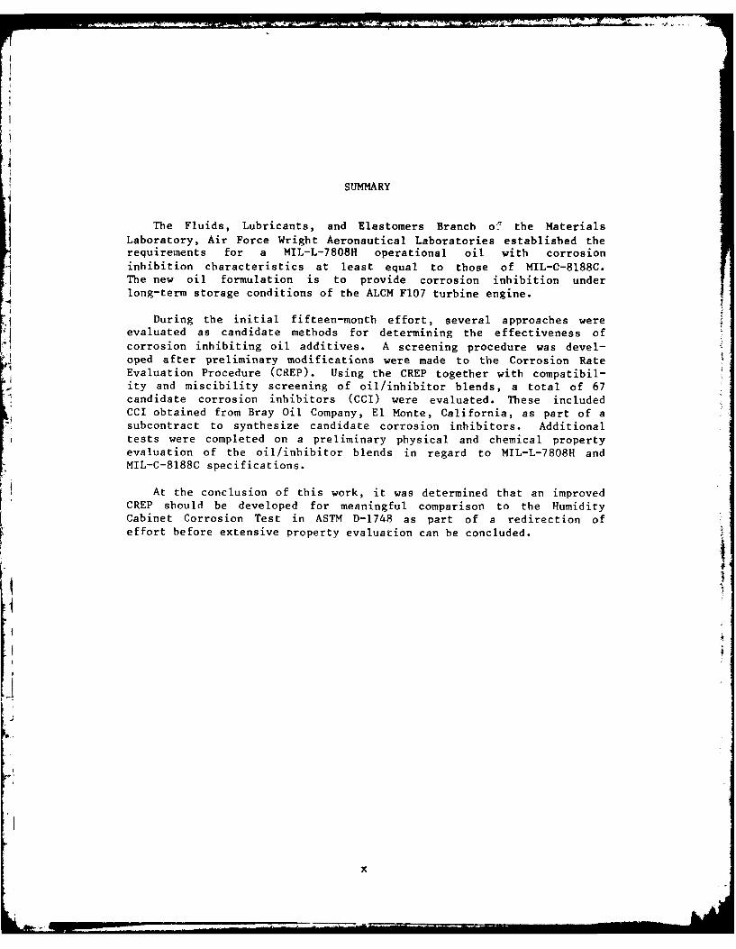
SUMMARY
The Fluids, Lubricants, and Elastomers Branch o2 the MaterialsLaboratory, Air Force Wright Aeronautical Laboratories established therequirements for a MIL-L-7808H operational oil with corrosioninhibition characteristics at least equal to those of MIL-0-8188C.The new oil formulation is to provide corrosion inhibition underlong-term storage conditions of the ALCM F107 turbine engine.
During the initial fifteen-month effort, several approaches wereevaluated as candidate methods for determining the effectiveness ofcorrosion inhibiting oil additives. A screening procedure was devel-oped after preliminary modifications were made to the Corrosion RateEvaluation Procedure (CREP). Using the CREP together with compatibil-ity and miscibility screening of oil/inhibitor blends, a total of 67candidate corrosion inhibitors (CCI) were evaluated. These includedCCI obtained from Bray Oil Company, El Monte, California, as part of asubcontract to synthesize candidate corrosion inhibitors. Additionaltests were completed on a preliminary physical and chemical propertyevaluation of the oil/inhibitor blends in regard to MIL-L-7808H andMIL-C-8188C specifications.
At the conclusion of this work, it was determined that an improvedCREP should be developed for meaningful comparison to the HumidityCabinet Corrosion Test in ASTM D-1748 as part of a redirection ofeffort before extensive property evaluation can be concluded.
x
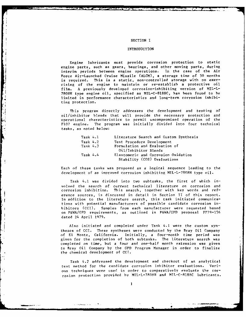
SECTION I
INTRODUCTION
Engine lubricants must provide corrosion protection to staticengine parts, such as gears, bearings, and other moving parts, duringinterim periods between engine operations. In the case of the AirForce Air-Launched Cruise Missile (ALCM), a storage time of 30 months
is required. This is a static, non-controlled storage with no exer-cising of the engine to maintain or re-establish a protective oil
film. A previously developed corrosion-inhibiting version of MIL-L-7808H type engine oil, specified as MIL-C-8188C, has been found to belimited in performance characteristics and long-term corrosion inhibi-ting protection.
This program directly addresses the development and testing of
oil/inhibitor blends that will provide the necessary protection andoperational characteristics to permit uncompromised operation of theF107 engine. The program was initially divided into four technical
tasks, as noted below:
Task 4.1 Literature Search and Custom SynthesisTask 4.2 Test Procedure DevelopmentTask 4.3 Formulation and Evaluation of
Oil/Inhibitor BlendsTask 4.4 Elastomeric and Corrosion Oxidation
Stability (COS) Evaluations
Each of these tasks was proposed as a logical sequence leading to thedevelopment of an improved corrosion inhibiting MIL-L-7808H type oil.
Task 4.1 was divided into two subtasks, the first of which in-
volved the search of current technical literature on corrosion andcorrosion inhibition. This search, together with key words and ref-
erence sources, is discussed in detail in Section II of this report.In addition to the literature search, this task initiated communica-tions with potential manufacturers of possible candidate corrosion in-hibitors (CCI). Samples from each manufacturer were requested basedon P&WA/GPD requirements, as outlined in P&WA/GPD proposal FP79-156dated 24 April 1979.
Also initiated and completed under Task 4.1 were the custom syn-
theses of CCI. These syntheses were conducted by the Bray Oil Companyof El Monte, California. Initially, a four-month time period wasgiven for the completion of both subtasks. The literature search was
completed on time, but a four and one-half month extension was givento Bray Oil Company by the GPD Program Manager in order to finalizethe chemical development of CCI.
Task 4.2 addressed the development and checkout of an analytical
test method for the candidate corrosion inhibitor evaluations. Vari-
ous techniques were used in order to comparatively evaluate the cor-
rosion protection provided by MIL-L-7FO8H and MIL-C-8188C lubricants.
After these methods were tested, a single Corrosion Rate EvaluationProcedure (CREP) was developed, improved, and later verified as ascreening test to be used for evaluation of each CCI.
The technical effort of Task 4.3 involved the screening and evalu-ation of 67 CCI on the basis of their solubility characteristics inMIL-L-7808H oil, and their corrosion protection capabilities as deter-mined with the CREP developed in Task 4.2. The CCI were screened toselect the 13 most promising, which were subsequently evaluated atvarious concentrations in MIL-L-7808H to determine their effect on thephysical or chemical properties of the matrix oil.
Work entailed in Task 4.4 was not initiated because of the need toimprove the accuracy and precision of the CREP and in turn decreaseits severity. Further work to modify the procedure is underway basedon the conclusions of this phase of the program.
AI
2
Ak 4
SECTION II
TASK 4.1 - LITERATURE SEARCH AND CUSTOM SYNTHESIS
A complete literature search was conducted to comply with the re-quirements of Contract F33615-79-C-5089 to evaluate the state of theart in corrosion inhibitors for MIL-L-7808H type aircraft enginelubricants. The key words selected for use in the literature searchwere based on the topic of corrosion inhibitors; i.e., corrosion inhi-bition, corrosion inhibitors, lubricant additives, lubricating oils.
Several sources of information were utilized to perform the literaturesearch, including a thorough search of DIALOG"1 (Lockheed Informa-tion Systems), Corrosion Abstracts/Florida Atlantic University, andthe Defense Documentation Center of the Defense Logistics Agency. Theliterature search included review of over 8,000,000 citations. A listof articles available was scrutinized to select only those references
related to the program. The articles were ordered through the P&WA/GPDLibrary Branch of the United Technologies Corporation Library. A copy
of all references was indexed and sent to the AFWAL/MLBT Program Man-ager on 28 March 1980. The literature search is being updated contin-uously as new articles are received. A summary of the referencesources is given below.
1. DIALOGTM (Lockheed Information Systems, Palo Alto, California)
a. Comprehensive Dissertation Abstracts (CDA) includes univer-sity dissertations of over 630,000 citations with monthly up-dates from virtually every American college and universitywithin the time span of 1861 to December 1980.
b. ClaimsTM Patents was searched using five definitive databases, as listed below:
0 "Claims/Chemistry: From 1950 through 1970" included over265,000 sources of US chemical and chemically relatedpatents issued during this time period. These also in-cluded foreign equivalents from Belgium, France, GreatBritain, West Germany, and the Netherlands.
* "Claims/Class" is the classification code and title di-
rectory for all classes and selected subclasses of theUS Patent Classification System. Over 15,000 sourceswere reviewed using this data base in order to facili-tate the other searches.
* "Claims/US Patents: From 1971 to 1978" which containsover 485,000 records utilizing quarterly updates of all
US patents was reviewed for corrosion inhibiting addi-tives in oil lubricant systems.
* "Claims/US Patents: From 1978 to the Present" containsover 85,000 records reviewed as above for corrosion in-hibitors for engine oil systems.
3
* "Claims/US Patent Abstracts Weekly" was reviewed inorder to supplement the above two Claims for the monthof October 1979 only. A total of 3000 citations werereviewed.
c. Metadex (Metals Abstracts/Alloys Index) from 1966 to presentcontains over 370,000 citations with monthly updates from theAmerican Society of Metals. These citations were reviewedfor corrosion inhibitors.
d. ScisearchR, a multi-disciplinary index to the literature ofscience and technology, was reviewed to the full extent ofits 2,700,000 citations. References searched were derivedfrom over 2600 of the major scientific and technical journals.
e. ISMEC, the Information Service of Mechanical Engineeringindices, provided a review of the significant articles of
mechanical engineering from approximately 250 journals pub-lished throughout the world. This search included over90,000 citations for corrosion inhibitors.
f. CA Search, covering Chemical Abstracts from 1967 to the pres-ent, including some 4,000,000 citations, was reviewed in itsentirety.
g. Smithsonian Science Information Exchange (SSIE) Current Re-search includes only the last two years, or some 253,000citations. This data base contains reports of both Govern-ment and privately funded scientific research projects fromover 1300 organizations that fund research.
h. NTIS, National Technical Information Service, includes cita-tions from reports of Government-funded studies.
i. COMPENDIX, an Engineering Index, reviews magazines and arti-cles in the engineering field.
j. Conference Papers Index reviews national and internationalconference presentations documented by publications in thearea of scientific research and development.
2. Corrosion Abstracts/Florida Atlantic University. These abstractswere reviewed through the reference library of Florida AtlanticUniversity at Boca Raton, Florida. The abstracts cover corrosionand its related effects, as published in technical journals of theNational Association of Corrosion Engineers.
3. Defense Documentation Center of the Defense Logistics Agency inAlexandria, Virginia includes reports from Wright-Patterson AirForce Base, Naval Air Development Center, Southwest ResearchInstitute, and other Government agencies.
The Bray Oil Company of El Monte, CA has completed the synthesisof several candidate corrosion inhibitors (CCI) under a subcontract to
4
P&WA/GPD. These CCI were incorporated into the total number of CCI
evaluated in this program. A final report was written by Bray Oil
Company, and copies were previously submitted to both the P&WA/GPD and
AFWAL/MLBT Program Managers.
-55d
SECTION III
TASK 4.2 - TEST PROCEDURE DEVELOPMENT AND VALIDATION
The primary objective of Task 4.2 was the development of an effec-tive, accelerated characterization procedure for the evaluation of thecorrosion protective capabilities of candidate formulations.
One method used to quantitatively evaluate the degree of corrosionis based on the use of buffered acidic solutions. The selection of
acid buffers was predicated on the acid level found in the precipita-tion of various locations in Europe and the United States (References1 and 2). Initially, a mixture of acids (2% hydrochloric acid, 28%nitric acid, and 70% sulfuric acid) that contained no more than 100parts per million of sodium, potassium, and calcium salts was used toprepare a solution of pH 4.5. One-hundred milliliters (ml) of thesolution were added to a series of four 1,000 ml PYREXTM reactionkettles and heated to 100 0C (212 0 F). Sample specimens were fabri-cated from 1.25 x 5.08 x 0.16 cm (0.5 x 2.0 x 0.06 in.) strips ofAISI 1010 low-carbon cold-rolled sheet stock. These strips weredrilled with a 0.24 cm (0.09 in.) dia hole at one end for suspensionwithin the reaction vessel. Each strip was prepared to a surface fin-ish of 10 to 20 microinches with 240 grit abrasive paper and cleanedin boiling toluene, then in boiling acetone prior to weighing. Typi-cal weights were approximately 7g. The reaction kettles were fittedwith a four-hole ground glass lid. Two of the lids were fitted withGraham-type condensers and the remaining two lids were fitted withAllihn-type condensers. All condensers were water-cooled and all re-action kettles were supplied with Celsius thermometers with bulbs pos-itioned 7.5 cm (2.9 in.) above the buffered solution. Each reactionsystem was placed on a heating element and supplied with a Teflon en-capsulated stirring bar. The acidic solution was initially stirred toensure an even temperature distribution of the hot vapor within thechamber. A series of tests was performed to compare corrosion on pro-tected (MIL-C-8188C) and unprotected strips. The results indicatedthat stirring was not necessary if the kettles were heated to 1000 C(212 0 F) and allowed to reach thermal equilibrium prior to introduc-tion of the sample strips. Thirty minutes was found to be adequatetime for equilibration. The sample strips were suspended from 21-gauge Inconel wire inside the reaction kettle approximately 5 cm(2 in.) above the boiling solution. These wires were inserted througha No. 5 rubber stopper and suspended in the temperature equilibratedreaction kettle.
A series of 24 tests was conducted to determine the nominal length
of time for meaningful test runs. These tests were conducted using a0.15 molar acetic acid solution of pH 4.5. An effective minimumresidence time was found to be 3 hours. No significant corrosiveattack was observed on test specimens suspended above the aceticsolution. An increase of two pH units occurred during the testing(ie., 4.5 to 6.5).
7
...... AWE. & Mk.44 ai F

The next solution to be evaluated was a buffer solution compoundedfrom citric acid and sodium citrate adjusted to a pH of 5.0. Samples
from initial testing exhibited a mild degree of corrosion. Four testfluids were subsequently made up of acetic acid solutions (pH 5) com-bined with up to 0.5 molar concentrations of sodium, potassium, andcalcium salts. Tests performed at 100 0 C for 3 hr, with four acidsolutions, showed only very mild corrosive effects. The final solu-tion of this series to be evaluated was a certified buffer solution
obtained from Fisher Scientific (sodium acetate, So-B-100). The pH ofthis solution was 4.63 with a molar concentration of 0.1 total ace-tate. Preliminary results showed appreciable corrosion after 3 hr at1000 C. Weight loss for cleaned, unprotected strips was approximate-ly 3 to 6 mg using this buffer solution compared to erratic resultsobserved with the other solutions during the 3-hr test.
In order to validate reproducibility, multiple tests were runusing identically prepared samples. One-half were coated with MIL-C-8188C oil and the other half were unprotected. Results varied gravi-metrically from 0.1 to 10.0 mg on identical tests using split samples
from the same aliquot of oil.
A problem was believed to exist in the sample preparation proce-dure that consisted of cleaning the post-test specimens with acetoneprior to weighing. A series of tests was then completed in an effortto establish a procedure for sample strip preparation. The procedurewas as follows:
1. A solution of 15 volume percent (v/o) of concentrated hydro-chloric acid was homogeneously blended with 1.5 v/o of P&WASpecification PMC 1015 (Inhibitor for Muriatic Acid)
2. Sample strips were prepared by surface finishing with 240-280grit alundum abrasive paper, then immersed for 10 sec in thehydrochloric acid solution, and immediately immersed in di-lute reagent-grade sodium hydroxide (0.1 molar)
3. Samples were then immersed in boiling toluene followed byboiling acetone, flash dried, cooled in a desiccator, and
weighed to +0.1 mg.
Corrosion tests run on unprotected samples using this cleaning
procedure prior to testing improved reproducibility compared to sam-ples cleaned by any of the previous methods. As expected, the testsconducted using MIL-C-8188C coated samples as opposed to unprotectedsamples provided greater protection against corrosive attack.
Simultaneously, a sonic cleaner was under study for coating strips
with oil/inhibitor combinations prior to introduction into the cor-rosive environment. This approach proved time-consuming with no ap-parent advantage gained over coating by immersing the sample strips ina beaker containing the oil/inhibitor combination. Work was also ini-
8
tiated at this time using a Corrosion Oxidation Stability (COS) appar-atus manufactured by Roxana Machine Works, South Roxana, Illinois.The unit can test up to eight specimens under identical conditions forany desired time duration and was used to perform comparative testing
of AISI 1010 specimens treated with MIL-L-7808H/inhibitor combinations.
Another corrosion test procedure under consideration at this timeinvolved the use of a Parr Oxygen Bomb. This procedure was evaluatedunder various conditions of temperature, oxygen pressure, and humidi-fying agents. Nominal test parameters eventually selected foroxygen-rich environmental evaluation of this procedure are shown below:
o Oxygen pressure: 0.2 MN/m2 (2 atmospheres)o Environmental temperature: 1000 C (212 0 F)o Humidity: 10 ml of 10 w/o sodium chloride in
water.
The term water or deionized (DI) water refers to water with an elec-trical resistance of 5 to 10 megohms per centimeter.
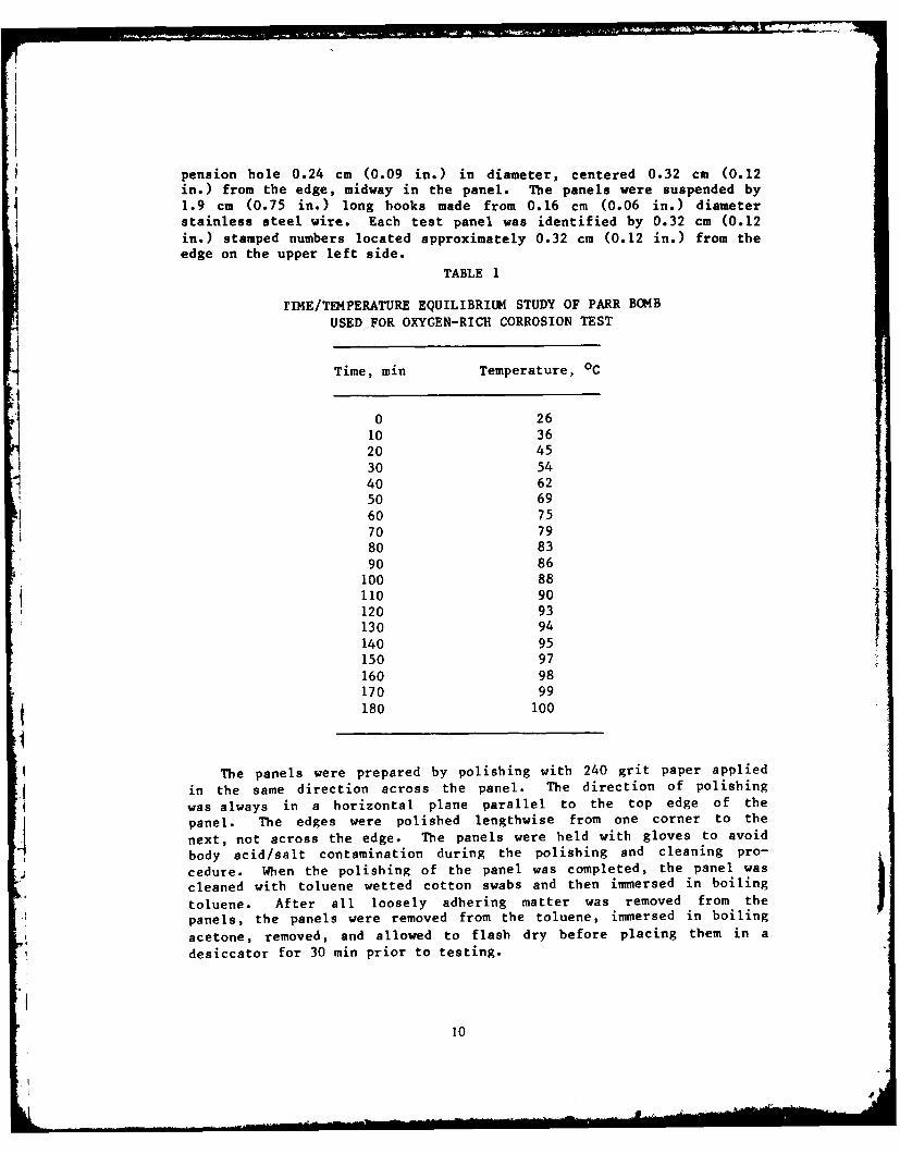
Initially, the test duration was 3 hr, but more meaningful resultswere achieved when the duration was extended to 4 hr. A time/tempera-ture equilibrium study of the Parr Bomb was run to verify the timenecessary for thermal equilibrium of the test apparatus. The testchambers were modified Parr Combustion Bombs. The modification con-sisted of removing the straight and the looped terminals used in thefiring circuitry and mounting a 1.6 mm (0.06 in.) diameter stainlesssteel wire across the terminal mounts in a horizontal plane. This wirehas four spaced hooks to accommodate 4 panels without impingement.With this design, 4 specimens could be mounted in each test cylinder
for simultaneous corrosion evaluations.
The chamber was placed in an Isotemp oven set and maintained at1000C. Temperature readings were observed with a Fluke DigitalThermometer. Sixty-five minutes were required to attain 770 C(170 0 F) and 180 min to reach thermal equilibrium at 100 0 C, asshown in Table I. During the 4-hr test cycle, the test specimens were
maintained at 1000 C during the final 60 min of the 4-hr heatingcycle.
Eight tests using water adjusted to a pH of 8.0 with KOH as ahumidifying agent were run early in the program (Table 2). The humid-ifying agent was changed from a weak potassium hydroxide to a sodiumchloride solution, which appears to be a more realistic corrosiveagent. The laboratory-prepared salt water used for testing was madeby dissolving 10.0 g of sodium chloride (reagent grade) in 100 ml ofDI water. The pH of this mixture was not controlled, but remained
constant at 5.0 + 0.2 pH.
Corrosion panels for the Parr Bomb tests were fabricated fromAISI 1010 low-carbon steel in the following configuration: 2.5 x 2.5 x
0.16 cm (1.0 x 1.0 x 0.06 in.). Each panel contained a single sus-
F9
pension bole 0.24 cm (0.09 in.) in diameter, centered 0.32 cm (0.12in.) from the edge, midway in the panel. The panels were suspended by
1.9 cm (0.75 in.) long books made from 0.16 cm (0.06 in.) diameter
stainless steel wire. Each test panel was identified by 0.32 cm (0.12
in.) stamped numbers located approximately 0.32 cm (0.12 in.) from theedge on the upper left side.
TABLE 1
rIME/TE4PERATURE EQUILIBRIUM STUDY OF PARR BOMB
USED FOR OXYGEN-RICH CORROSION TEST
Time, min Temperature, °C
0 26
10 3620 4530 5440 6250 69
60 75
70 7980 83
90 86100 88"110 90120 93130 94140 95150 97
160 98170 99
180 100
The panels were prepared by polishing with 240 grit paper applied
in the same direction across the panel. The direction of polishing
was always in a horizontal plane parallel to the top edge of the
panel. The edges were polished lengthwise from one corner to the
next, not across the edge. The panels were held with gloves to avoid
body acid/salt contamination during the polishing and cleaning pro-
cedure. When the polishing of the panel was completed, the panel was
cleaned with toluene wetted cotton swabs and then immersed in boiling
toluene. After all loosely adhering matter was removed from the
panels, the panels were removed from the toluene, immersed in boiling
acetone, removed, and allowed to flash dry before placing them in a
desiccator for 30 min prior to testing.
10
0 Q 00 0)1
OD 0.0. 0 o 0.r 0 1CO
r. 0 0 0ot 000C U .
0000~~~ 0000 1 1
CL a.0C 0-. m0 00 toot 0
41 . 1 1 ~ 00 0 0-)* - - . CIl -.. I
o > > > > > > I~. - - 0 > 0 0 r C C .r 0 )
0) 0 0 a) 0 0 0 0 00 00 0) to IV. OD . 0 0 to 0 00 00 to 00 t- m0. to to C00 00> 1-.> C:1-r-1r v>> - 0oC rC C C o 0 r r CL c o or
1-I I- I. I4 - 1 - -"4 -1.1 0 0) 0 -- - ' 1-' 0 0 0 k k- 1- U 10) 00 0 0 004 "1111-- .- 1- 1- 414 w'1 1)-- 41
to0 UUO0 QU4 -0 0 01 1-10 0w 4114. CCC1 000)1-w00140)0))).1011141)1. 000.0. 0. 0 0 ". 0.010)Z .4W0
.0I W W. 0) u.04111 0 CL 0 01 U1 00.t, C 114 CIL,.. vo 'a-40.W w 0 0111. C C0 0 C -I 0 14 00a)0)).w.
'y> 400 0 -t $) L,)0. '04 a0 ) N-444t w0' 00)0w
to ) a) 0. v 41 41 41 U) 0. to 0) 0) I) I- w w- U oo C1 o t C U 7 0 14 0 CD 14.m4.4 w 'vVloV. o80 to > 1)40 w w) 0)>to o I o o 0 0 0 o 4 o44 0000 01$00 41 oo m1 w o)0ao o)) 0
'0 ~0 c41 a- .- 4 7.t7 0 '0 >. C C C 0 1- N0 0 C 0 o
0000 0 1 0 1l0 0 z 0. 0000 w a 0 00 0-0 0 D 0 E 0
0 >
00.~00 rm Ia.- .0 00 00 000 000 00-- to 4) ~ l~ 1 1 1 toW D ob oWZ I4$ lW S , 1 _Z
0w- H>0m>- >~ o oowoo t
C.) c) w c r~ r~- > w C CC CC C C >
o 01 z) 00 : )1wQ 4 ) w4 j(*~t .) v)C'C v) E-1 .v) U)- >440--- >4?4444400
0- . - - . . . . . . . . . . . . . . . . .
u 0 r-. ------ ar-1 - .-4to~ro ooc
w 41------------o-c c co o c oc oc o
0000 ---- 0
00oo o ~ o 00c 02 0~22 --- .- -*.---- 1--.-
W c Wq - - - - - C4 0C4 N N- N- N- - N N
m. ID o lo D 101 ID o o m N 000 00 0 0 0 0 0 0 0 0 0
I co cc oooo)0
o ) 6 4"4f. o)0 0o NC00o)0 )0O00.-NGo(41't.01c -1'-- - - 4 aN N N N- No(0-C1-C1C
0z t 4 4) ca "
.0 4) a)CC
w4- v4 DC.~ C v 0 )
w .0 00 0 000 ) 00 m 04). 0C ' 1 C 4)0 .1 O. w '4 )a."-4C) C 4) 0c E 0 :14
044- 'o w4 r' cc 06 'C c
0 M44 '. 4 ) 0 > '0O , 0 '4 m C -0)2 w 10 . wU .40 -E w) E) ) 0w'c 4 0 w >' '4 w 0 -4 'C N 11 C- U 4'4 00 C W. . M)' 0 "' tC.) '.4 00 to oC) 0 '4 L >
> C C0 )4.44' 4.. 4C 4 CC -mC O to 4)0wa
.a -'C4 ) C4C4 w.C m4 .' 1) w.000 '4 4 0
4Dm) 0 '4C4 4.4 )' C 0. 0 554 E4a
$4 W. 0' C 40. " 0 .' > a, 0. .. w W C D). CL . ' C 0W 0'U CID4 0. 40 4r. S. w.~ .w 4 rC to r44.4.. w .2 'L w)
0. 44 -4-4454- 0 . C '-4. 'D C a) 54) '4
W .0, X 00 4 U4..> 4) 441 4 '444 > '4
0 . 00 .0 0C.. to. to 0 0. C 0 a) E -4)aj C C 4 ,CC) C,, > ) C C , C 4) 0. > CC -0 . .
> . 4 ' . '4 U -. 4 . . . . . C ' . 4 -4 ' C ' C '
4-'4W) >,> , ,N
'4W4.4$I r0) 1 1 ..(DC 0 4 ' 4.4a'. 0 0 '4 - . . 04'. .~ - .4 4'
0 '444 CCC C C C CC C C C C C C C: CCC C C Co~~~ 0 0..-. 4)))))))4444444 C) 4) 4) 4) 4) 4) 4 44 ) 4) 4) 4)
4. Q/ w -'.4.w Q w Q
u w o. UUUUUUUUL)UUUUU u u U) u u U U UUU)U u--- -- -- -- -- -- -
w WE 0 0 00 0 88 0044. '. 04 N 0 40 0. 4'. Coco'.' 40 40 c. c.
u00000000 00 0coo0 0 0 0 0 0 0 0 0
x 4) 4 4 4 4 4 4 )4 ) 4 4 4
e4 en C0. 00D -T' 4 1 0 m m 1 0C-0. 0000000 0000 000.0.00.00. r000CO.0.OC 0
w 0 o 0. 0 0. 0 0 .O 0 0 00 0 .000 O 0. 0. 0.
w) 0,4 ) (v Q uCL C0. 0. "CE CL000 OO O 0O O0 00 0 0CLo 0
9:z~~ z z z C C: C: C a c z r r r a
...4.4'4 U4 O .. . 00 r 0 0 4 0 0 0 0' 40 4 44') 40 ' 0
123 , 3
~~04 &
z4 C.C Z4Q)4 0 r 0
>0 1 $
,a m a) 4.4
00 C:C0aa -4 >4
44 044 000 0 00 44 -4 0 0 040 0) 0) a) Q,
04 04 C 0 r- >4 4 4 0
me b. 00 to 04 04 04 4) .o 00 CI4WW)O>- 0 ) r c 4 r -t r c a C: C4 a,
I4 I ~ I0 t 0 .0 a - 0 0v ) v) IV C.0 0 r- CL 0) C . 04
-- 4 w 00 0 0 4) CL aC ) 4) 4)) w4)W)j Ev a 00 0 00 0404 > w > >
W $ 1 0 4 C C C) 0 0 C C C CC 0 04 C) w 04 C0 )0 0 00C C C -0 - -0 4 w4 $. w''. 0 C E4 C C 0
00j J i .4 0 - .0 . 0 04 04 .4 .04 0 0 0 0 0
W0W000W0 C - = =--X4lc :4) a)a 4) -I W ,tu t 0 0
z 0004.4.C) 0 .C 0 0 a a 4. cc 0 0 .0 0 C 04) )4 4 .4 4 4 .- .0 0+ 04 +4 +) +) + + + 04 0 + +4 +
0) ) ) ) Q04 4) 4) a ) a) 4 ) 4) 4)4C) 4) 4) w - 0
.C 04 mUhf f m r -m - 4 m C 0 m M 4T m 4 m .4m ' 0 m 0 m4T m4T m~ 4
z zz zzC zz z z z
-w442 0 000 00 0 0 0 0 0 0 0 0 00 0 0 - 0 0 0 00 , 00. ++ + ++ + ID 0 0 2, 4+ (D 2 4 0
0 4
-. 4 0 0C a a a a a a a a a a a aa a 4 a a a a a
C) 000.IC)U 00) o. o o. o. . 0 0 ) 0 o 0. a 0 0 0 0 0 0..
m -
C.4 00. 00 0 0 0 00.)-Ca4o 0 x0 0) 0 4 0 0 0 0 0 0 0 0 0
Q4 JI.ZZ0 Za.4 0. CL CL0 0 0040 04 CL m 04 CL CL 0z~~~ .-- z-4.-- 4-- -4 -4- - --. -- -. -4 4-- -4 -- -M - -4 4- -z 4-- -4- 4---
in . 0 0 0 0 0 0 0 0 0 0 0 0 00C 0 0 0, 0 0 0 0
0444.NN=44N44=NON= N = N xNx= N = N QNON N N N N M ON UN4)0200 0 w w w 0 0 Go0 0 O o 0 c 0 c
M.0 4400 C 000C o000000000000C
-- - 4- - - - - - ~ -- - . 4. -. .- 4-. .-
0000 00 0 0 0 0 00 0 0o c 0 o ON 0 a0
0440044 40 0 4 4 4 4 4 4 4 04 04 04 040134 0
LC

0. 1
04
*0 40 0 0
44 0 0 0.. 04 04
04 C004 0 0. 0. .o 0
.9 -4 to4w 4 r4 )) . 4) 0) 4 4
04 M4 E4 0 4 4 4
0 0. ) a w. 4. 44 4. .4
04 0 E4 0) 0 u 4 u
< CL 0
w44044 04) 04 4 04.4 4. :3"4 .4 *0 *' 0 *-. x4 - 4 4
U c' ~ 40 44 Z (0 Ez0
40-
z '~0C--4 -n 0A -4 N
00 0 + o + 0 + 0 + 0 + 0 + o 0 m
04 04 "C . r .C4 44 a) 0
04 ~~ ~ w440 04 04 04 C40 40 0 0.14.44 0 44 0 0 4 0 4
.9 C N
3k4 C. 31 3t~ 31 C4 .4 . .4 00,--Sr- c . r_1
440~~~~1 C.) Z Z Z ~ 44
44 0 0 00 00 0 0 0 0 CD 44Go.0 0 0 0 0 O 00 -0 -0 - 0 w 44 4
o 044 44 1 ; C;.4C
440 00 4
14 1

Three different methods of applying a test oil film on the panelswere evaluated: (1) 30 sec immersion in the oil and 15 min verticalsuspension at room temperature, (2) 30 min immersion in the oil and
60 min vertical suspension at 1000 C, and (3) 30 sec immersion in theoil and 30 min centrifuge at room temperature at a speed to impart arelative centrifugal force (rcf) of 560 to the panels. It is believed
that this last method provided the more severe test, due to thereduced oil thickness remaining on the test panels.
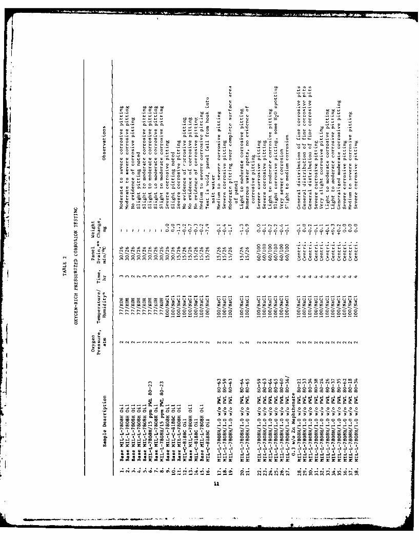
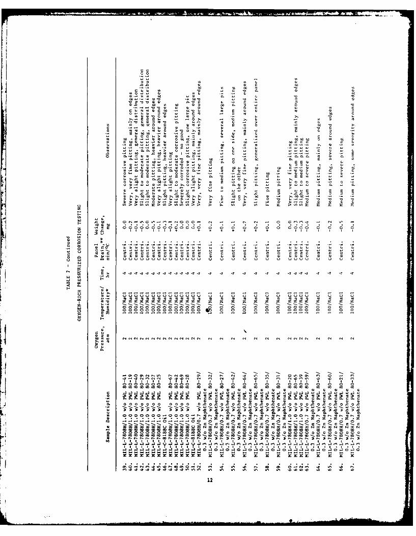
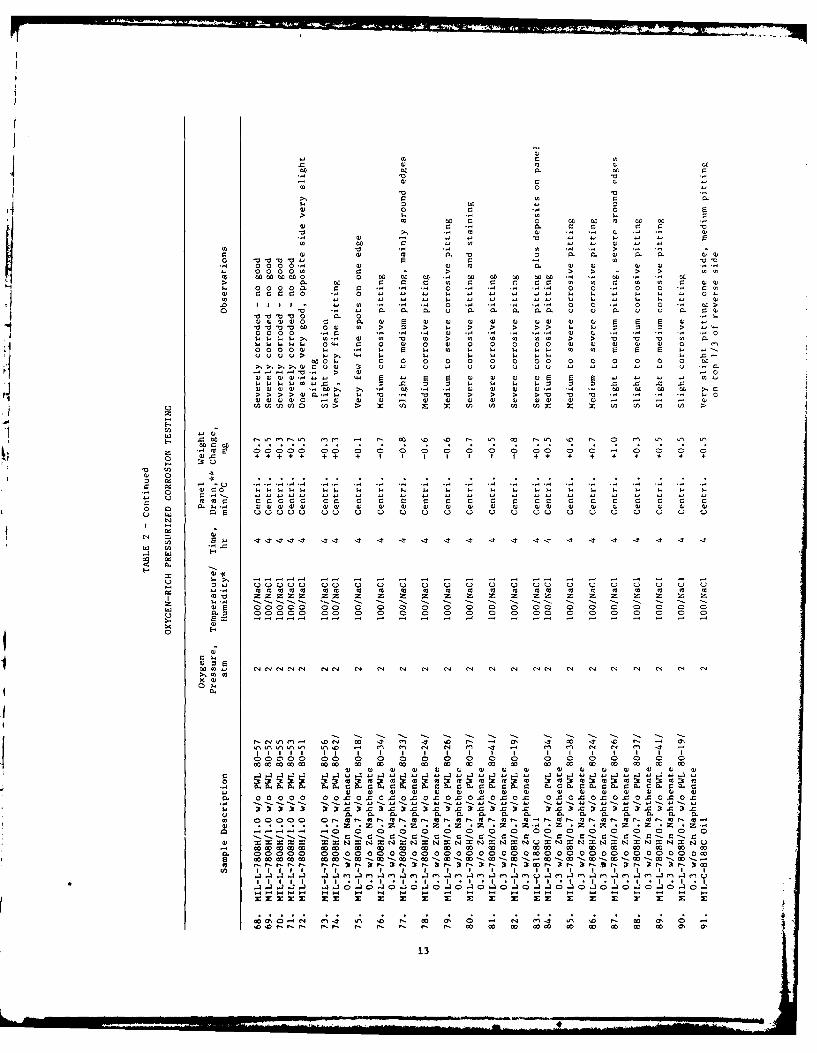
Ninety-nine tests utilizing the pressurized oxygen bomb procedurewere run, as shown in Table 2. The same observer was used in each
test. Test cycle times of 2, 3, 4, 5, and 6 hr were used to determinean optimum residence time for meaningful severity to give conclusiveevidence of corrosive attack. The time/temperature study of the ParrBomb (Table 1) indicated that a longer residence time was required to
reach the desired test temperature. Therefore, the 3-hr test wasreplaced with a 4-hr test. A 5 or 6 hr test was deemed to be a longertest cycle than was required for meaningful data generation.
The final test procedure involved weighing the pre-polished cleanspecimens to +0.1 mg, oil immersion for 30 sec, centrifuging the coat-ed specimens Tor 30 min, adding 10 ml salt water to the test cyclin-der, and suspension of the samples in the cylinder. After sealing thecylinder, it was pressurized at 0.2 MN/m2 oxygen and placed in anoven at 100 0 C. At the end of 4 hr, the cylinder was removed, vent-ed, and the test specimens removed. The specimens were cleaned byagitation first in boiling toluene and then in boiling acetone, flashdried, and placed in a desiccator to cool for 30 min prior to weigh-ing. After weighing, the panels were examined with a 1OX magnifier.
The entire area of the panel was evaluated, except for a 0.16 cm (0.06in.) border around the four edges.
One of the two objectives of this technical effort was to estab-lish an effective accelerated test procedure to determine the cor-rosion protection capability of candidate inhibitors. The oxygen-richprocedure developed for this program showed some potential for quali-tative and quantitative corrosion assessment. This procedure producedmeaningful data, but with considerable data scatter observed in theapparent corrosion of the same material run at different times duringthe course of the testing. A preferential corrosive attack on oppo-site sides of the same panel was found under the static test condi-tions of the Parr Bomb test. Further investigative work on this typeof procedure was precluded because of such anomalies.
A humidity cabinet test was used to evaluate the degree ofprotection afforded by the oils and their protective films to metal
surfaces. The length of time required to satisfactorily execute thistest is prohibitive when large numbers of samples are to be studied.The method is qualitative because only visual comparisons are madebetween sample specimens, and allows for variations between differentobservers. An accelerated test procedure was also considered utiliz-
15
ing the ASTM B-117 Salt Spray Test in conjunction with centrifugingthe sample specimens prior to testing. A series of preliminary
evaluations was conducted to determine the protective capabilities ofMIL-L-7808H and MIL-C-8188C with the accelerated test and to establish
the test parameters necessary for comparison to humidity cabinet test-
ing.
The humidity cabinet tests were conducted in a PrecisionScientific Company Model 21174 humidity cabinet. The temperaturewithin the test environment was maintained at 49 + IOC (120 +
20 F) throughout the test. The test coupons employed in theseevaluations were fabricated from AISI-1010 low carbon steel. The 3.8X 10.2 X 0.26 cm (1.5 X 4.0 X 0.06 in.) coupons were prepared
according to the procedure defined in ASTM D1748, item 7.3, using 240grit aluminum oxide abrasive cloth. The test coupons were then
cleaned by immersing in boiling toluene, followed by immersing inboiling acetone and flash drying. Test coupons that were used formore than one test were thoroughly refinished and cleaned with thesame procedure prior to reuse. The test coupons were immersed in acandidate corrosion inhibiting formulation, then suspended in thehumidity cabinet from suspension hooks formed from 21-gauge AMS 5837Inconel wire. Formulations were tested with various residence times
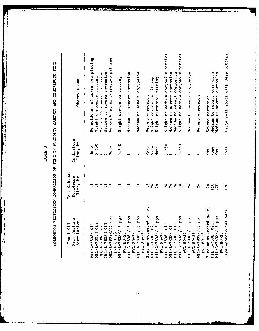
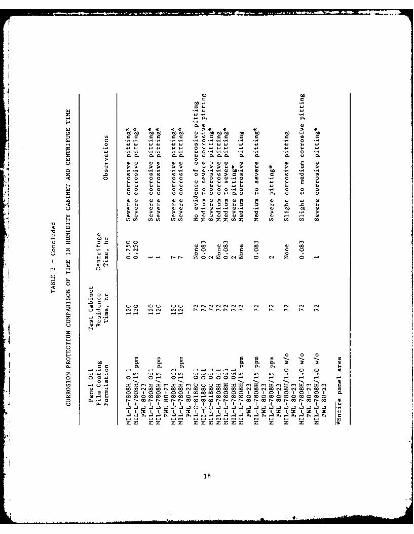
in the humidity cabinet. All post test evaluations of test couponswere conducted by the same observer. The results of these tests areshown in Table 3. The uninhibited MIL-L-7808H lubricant failed aftera 24-hr exposure, while the MIL-C-8188C did not fail until after a72-hr exposure.
Centrifuging of oil-coated specimens to reduce the thickness ofthe adhering oil film, thereby simulating oil film loss during long-term storage, was evaluated early in this program. Precleaned oil-
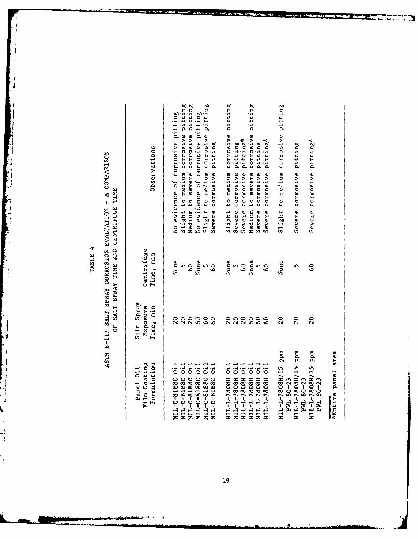
coated specimens were centrifuged at 2809 rcf for time intervals of5 min, 1 hr, and 7 hr. A significant decrease in corrosion protectionwas found in one hour centrifuged samples compared to 5 min samples,but the extended 7 hr centrifugation did not prove to be meaningful.Table 4 depicts MIl-C-8188C protected panels without corrosion after
one hour salt spray when not subjected to centrifugation, but failingin 20 min after a 5-min centrifugation and catastrophic failure aftera 60 min centrifugation.
Additional test specimens were prepared and evaluated withthe Salt Spray Test (ASTM B117). Preliminary tests with various salt
spray exposure times showed that specimens protected by MIL-L-7808Hoil failed after a 20-min exposure, and coupons protected byMIL-C-8188C failed after a 60-min exposure. It was determined inthese preliminary tests that a nominal 60-min exposure to the saltspray environment produced essentially the same results as were
exhibited after 72 hr in the humidity cabinet. The salt spray test,which included centrifuging the specimens for 5 min prior to theactual test, was used to evaluate approximately 35 oil/inhibitor
formulations. The matrix oil was MIL-L-7808H with 1 w/o of the
16
400 00 00
00 00 ... 4 .,
-,4 4.1 4.1 '.1441 4.1 ,4 -,4 -A.1 41 Q. m.0
0 0 0 0 > 00 > 0 0 04) 00..4..4 w) 00 -H .,4 0000 *.4"...4 4 - .4 *,-4
c -.4 0 0-4 -A. 0 0 r.4 r4 0 0 00 0 0 01-4 0 "n4.$4 $4 0 4.4 w w. Ag 41 4 4 1.4 w~. $- $
0. I." $4001.0 "4 0 0 *.4*, 000 0 00 $.1Z 41 1.U - 140U1 . 0 0 0.0 0 000 0 0U 0 &
> 0 01.4 uU)w)Uu 4) 01 4) C 4) w UU) 4) C C))
>) $14$4 > w~ 14i 0 > V$414: 1.4 0 01). W .144 '4.4 4) ) 44 -4 4) Q) .4 .,4 A JUw..AI ) *-4 *.44) ) 00.t I> > 0 >n > M )(A V > anc > (4 9) >~ 0>
0 0U) ) 0i w) 0 000 w w w w wU 0 0 ) )U)1w oUmU l$a V) In 1.141. S o m en In w. W.u )
EH U). U4 Q ~ w 1. W 14 w.ww OOO0 0 0 0 0 00 0 0 00 0 0 0 0 0z wuJ-"4.jU U -4 4.1 UU 4J1.41. 4 .1 UJ -6J4. u
P-4V 144 E S Li.1L 9.2 L 'L U) S
w b 4) 0.-.4 Q) 00 .4 .. 4 Q) 000 00 *'. 00 -4.-4b 01 0)....4 M 00i
0 0- )4) 0 -4 0) U) o~-.. -4 4) a)-4 4) Q cu ) ) (o
z n z c AV)M w c o U
00 0 0Ucu w n 4 r)FW )) ) irN e (U ) 0) Q)
-.4C C4' a C4r r C 1 4 r_4 CCC c c11441.U 0 * 0 0 000 0 000 0
J4 F- -r'Z 0 - .4 r- .Z Dz z 0.-. z- z- Zz z-~4
E-4-
rZ4
0
CO --4U.
E-4 -
4.4 0 -4-- -4--4 4
0 c-4 -
C) 0000 UDI)IC 0 1 00 1 1 1k0c IS
M o0 00 000 0000 0 t. 0. 0. 0. 0. 00c 0. 000 0. 0 . 0A CC40 r r -P 0 r 0 00 r 0 0 0. r 0 .-r -- r 0r 0 r 0 rr- 00
.1 04 -. .. 4 ~ 4. 1 04 .4 UC 4 CL1A 14..l A. *.4..4 - 40 L u. W .1 .4 0. 4
P-44-4--4 P-4 M -4 1-4 U -4 '-4 -- 4 4--4 P-4 CU 4-4
-- 4 to
17
c C:cO0.-4 ,
w -4 AA. 4
z '1 .- 4m-4 4 n
r.o c cr_ co c,0cc >c cc cc C: r. C0.00 C-4 *.4 -4.- H -4.4 .,4 0 . 4 .-. 4 -4 .,4 -4 0 *-4
0 A~i 4J4. U4J (A~ I4 .J4" U41 i4 w A- . 4.. 41~ "J 0 $4 Li J 4- 41 4.. 4.4 $A4 41
-4 *-44 *-4.-,4 -. 4 -.4 W.40 -4 -4 -4 -,4 -.4 -A4 0 -4m0 0 C C. 1 u 0.00. 0. 0. 0. CL0 .
>i 0Q P- w ) w)0 w 0)wW0 ) 0).) 0) 0) w) ri w
U) *-4 H **-r4 -4*r 44 wr4 k w00.k ) cc ., -,4 -,4C0g w coM r (A 0 ( fl P.I to( r C W
0 0 0 0 0 0 0 W0 00W -4 0 0) r4 0 0) 0w.41- 1.4 4 w.1- w 01 41.4 24l 4 CW A -4 r= w.4$- -14 w $14 $41. 0 414 4.1 $4 44 w. 1-4
0i 00 0 0 0 0 r.0 00 0-4 0 0 ~4 0 0 0
00 u u 0 Q 00 (L) 1 u Q Q 41 0 u 4.4 u
0)0 00) 0)) .4 0) 0) 5 w) 4-4 4- 0)00)0a) Q)0)0) 0)0) 4 4Q 0 . 4 ) 4 -4 0) 00 b0 0)
00) w cu ) a)) Q ~ )) 0ww a) w4 .4 -4 w)
1-4
0) m l
14-4V 0)0 00 )00 a) 00 a) 000 z -4 r-JC C0 0 0 0 r_ 0
W - 10 C *C 0 * 0 . 0 *0
4--j C 0 - r- r- Z 0 C-4ZeZ 0 C4 Z 0 C* z
C:4E-4
E-4 Z 0
0 $
E-4
0 0 0
0. 0. M .J0. 0. r-4 0 - 1.41-4 0. m. 0 . 0
cn -4 U 40 4. 4.4- 40 0 0 C
o l -(044 0. 0- P0 00 00 w' rw- w-4 -w - 00 011 4-j-4-4 J-4 -4 P-4 -4 " -4 -4 -4 -44-4 -4 1-4 0-4 -4 -.4 -
18
60C to 00 00 wO
bo H4 .4 bO -,4 ...4 -,4 -0 j AjJ- M 41 4 A-i
.4 .
4).4-4 M ( -4 60 -4 CO 00-4CC 000 4 00 OU) >~ W W U) Co > (A wacC: 0 Z r
Z 0 - 00. 0- 0*-"--0*44 0 *'-q .,I0 $-0 44 Co w4- 1 $.Ai~~4 . A . A-i
-4 0 WW0 W " 1. $ A-AJ i.j j Aj 4-i A-4 04 w- . 1 0 -4 0 4.4 0-4-4 0 -4 .,
> 0 0
0 "a > > A U nw V 0 Uq~ 4) JV0 G0 0 w00 w) 0 0
0 0 0 000 0 00 0 00 0 0 0w Ai.OJ 41I UJU wi U uu u
C, -, r)o- 4 &OJ w O JJ-4 G AoiJ044)>-a GJ >-AaJwJ0=0WJW- 0 P
4)- Q)) w0)tow w ) 00)-4- .,4~ >U~ -it4 > i~ > Vt 0 ,
0- -4 W '0 -4 0 '00 w 0 0) ww
>0 W
F4 ~ ~ 5- W..4 0 .04
~0 E
04 U)
00 00000 00 C 0 0. 0
;rl ". 0. 0. -
-4 4 - -4.--.l -4 - -4--4 0c-O -,4 4 , -4-4 -A4 -4-4 -4.4 V) II f
-44 0 00 0 00 0 00 0 00 -4 - 4 -0 .41 .-.- - -
000 oc 00 0 0 000 0 01 0 10 1 0.04S0w
1.9
various additives. The initial screening test utilized an exposure of onehour of the oil/inhibitor-coated specimen, as shown in Table 5.Comparitive evaluations of various corrosion inhibiting oil formulations
indicated that the better or more corrosion resistent formulations provideda longer life expectancy in both media.
A Potentiodyne Analyzer was evaluated as a method for rapid deter-mination of the electrochemical measurements of corrosion rate. The
sensitivity and application of the instrument have been evaluated. Initialtest cell design and procedural analysis indicated that the development of
this instrument for corrosion measurement was beyond the scope of thisprogram because of the need to also develop a compatible electrolyte.
Much technical effort was spent in the final development and vali-dation of the accelerated Corrosion Rate Evaluation Procedure (CREP) for usein screening the corrosion inhibiting characteristics of candidate corrosioninhibitors. As previously mentioned, the CREP utilizes a buffered acetatesolution at 1000C with a dynamic airflow system maintained at a flowrateof 45 cc/min. This procedure has been written in standard form as given bythe American Society for Testing and Materials (ASTM) and is included hereinas Appendix A, along with supplementary notes concerning use withMIL-L-7808H type engine oils.
During this period of development, several problems were encountered
and eliminated. The first of these involved the development of a repeatablemethod of surface preparation for the specimen. It was found that
significant differences existed between the samples using identical reactionkettles, and even within the same kettle. This problem was reduced, but noteliminated, by the development of a new cleaning procedure. Another problemoccurred because a film developed on specimens in the acetic acid bufferswhen the molar concentration was greater than 0.5. The test procedure wasmodified to allow a maximum molar concentration of 0.1 in total acetate inorder to eliminate this problem. A further problem was found to occur withtwo of the three types of rubber stoppers used to support the specimens.
The acetic buffer solution attacked the exposed surface of the stopper andresulted in deterioration of the stopper. Buna-N stoppers were found to becompatible with the acetic acid vapors under tOe test conditions describedherein.
Contractual obligations stipulated that 10 fluid samples furnished by
the AFWAL/MLBT Program Manager be evaluated for corrosion protection. Thesefluids were to be ranked as more effective, less effective, or equivalent to
MIL-C-8188C oil in corrosion protection.
Prior to receipt of these samples, 15 CREP analyses were conductedcomparing corrosion protection of MIL-C-8188C to MIL-L-7808H oil, as shownin Table 6. The data reveals that the CREP analysis is capable ofrepeatedly differentiating the corrosion protection furnished by the twooils.
20
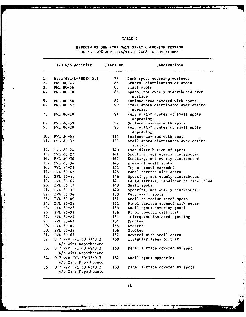
TABLE 5
EFFECTS OF ONE HOUR SALT SPRAY CORROSION TESTINGUSING 1.0% ADDITIVE/MIL-L-7808H OIL MIXTURES
1.0 w/o Additive Panel No. Observations
1. Base MIL-L-7808H Oil 77 Dark spots covering surfaces2. PwL 80-43 83 General distribution of spots3. PWL 80-66 85 Small spots4. PWL 80-60 86 Spots, not evenly distributed over
surface5. PWL 80-68 87 Surface area covered with spots6. PWL 80-62 90 Small spots distributed over entire
surface7. PWL 80-18 91 Very slight number of small spots
appearing8. PWL 80-59 92 Surface covered with spots9. PWL 80-20 93 Very slight number of small spots
appearing10. PWL 80-65 114 Surface covered with spots11. PWL 80-37 139 Small spots distributed over entire
surface12. PWL 80-24 140 Even distribution of spots13. PWL 80-27 141 Spotting, not evenly distributed14. PWL 8-30 142 Spotting, not evenly distributed15. PWL 80-34 143 Areas of small spots16. PWL 80-23 144 Top of panel corroded17. PWL 80-42 145 Panel covered with spots18. PWL 80-41 146 Spotting, not evenly distributed19. PWL 80-69 147 Large streaks, remainder of panel clear20. PWL 80-19 148 Small spots21. PWL 80-31 149 Spotting, not evenly distributed22. PWL 80-34 150 Very small spots23. PWL 80-40 151 Small to medium sized spots24. PWL 80-26 152 Panel surface covered with spots25. PWL 80-28 135 Small spots covering panel26. PWL 80-33 136 Panel covered with rust27. PWL 80-21 137 Infrequent isolated spotting28. PWL 80-67 154 Spotted
29. PWL 80-61 155 Spotted30. PWL 80-39 156 Spotted31. PWL 80-63 157 Covered with small spots
32. 0.7 w/o PWL 80-31/0.3 158 Irregular areas of rustw/o Zinc Naphthenate
33. 0.7 w/o PWL 80-42/0.3 159 Panel surface covered by rust
w/o Zinc Naphthenate34. 0.7 w/o PWL 80-35/0.3 162 Small spots appearing
w/o Zinc Naphthenate35. 0.7 w/o PWL 80-65/0.3 163 Panel surface covered by spots
w/o Zinc Naphthenate
21
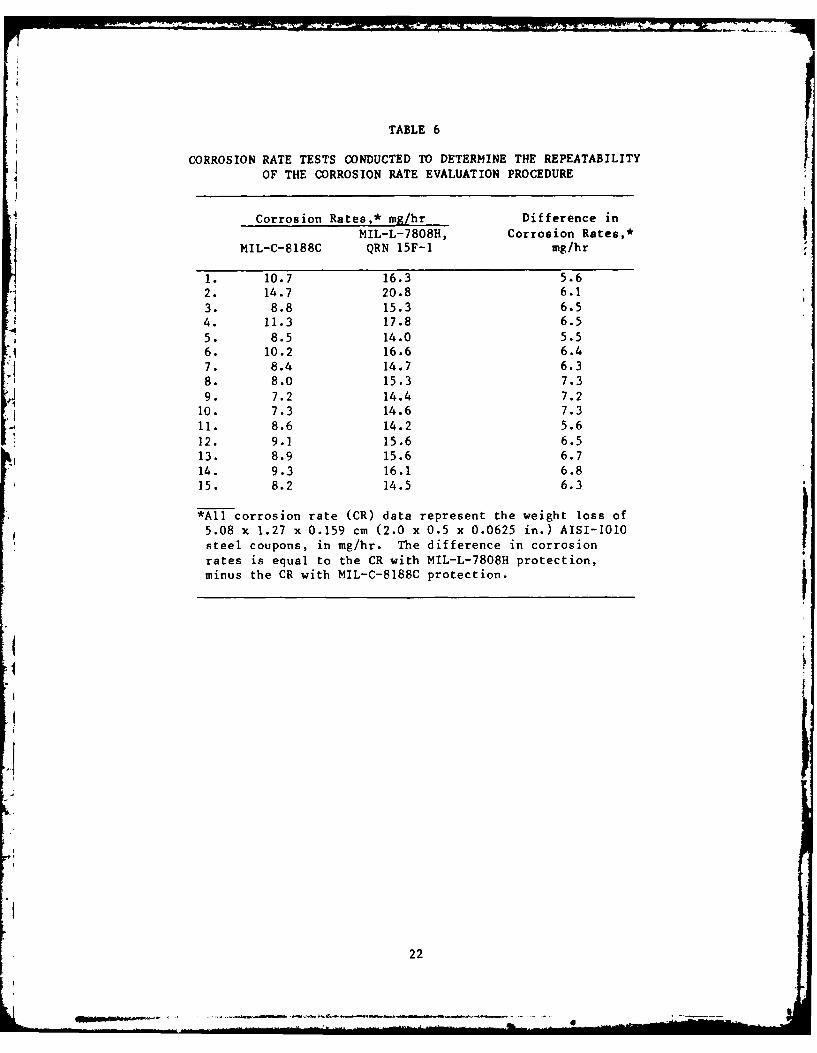
TABLE 6
CORROSION RATE TESTS CONDUCTED TO DETERMINE THE REPEATABILITY
OF THE CORROSION RATE EVALUATION PROCEDURE
Corrosion Rates,* mg/hr Difference inMIL-L-7808H, Corrosion Rates,*
MIL-C-8188C QRN 15F-1 mg/hr
1. 10.7 16.3 5.62. 14.7 20.8 6.1
3. 8.8 15.3 6.54. 11.3 17.8 6.5
5. 8.5 14.0 5.56. 10.2 16.6 6.47. 8.4 14.7 6.38. 8.0 15.3 7.39. 7.2 14.4 7.2
10. 7.3 14.6 7.311. 8.6 14.2 5.612. 9.1 15.6 6.513. 8.9 15.6 6.714. 9.3 16.1 6.815. 8.2 14.5 6.3
*All corrosion rate (CR) data represent the weight loss of
5.08 x 1.27 x 0.159 cm (2.0 x 0.5 x 0.0625 in.) AISI-1010steel coupons, in mg/hr. The difference in corrosionrates is equal to the CR with MIL-L-7808H protection,
minus the CR with MIL-C-8188C protection.
22
*. M . ... ~ .*
Ten fluid samples were furnished by the AFWAL/MLBT Program Managerfor validation of the P&WA/GPD-developed CREP and were evaluated fortheir corrosion protection capabilities relative to MIL-C-8188C. Theresults of these analyses were forwarded to the AFWAL/MLBT ProgramManager, who has reviewed the data concerning these validation samplesand responded with a letter discussing the results of the tests. TheAir Force has accepted the CREP as an adequate preliminary screening
test. P&WA/GPD is currently initiating effort in an endeavor toincrease the precision and repeatability of the CREP at the request ofthe AFWAL/MLBT Program Manager.
23
23
SECTION IV
TASK 4.3 - FORMULATION AND EVALUATION OF
CORROSION INHIBITING ENGINE OILS
Three different samples of MIL-L-7808H aircraft turbine enginelubricants were acquired to formulate the candidate corrosion inhibit-ing engine oils to be evaluated during this program. These lubricantformulation stocks were selected from the MIL-L-7808H QualifiedProducts List (QPL). The acquisition of three oil samples was basedon the fact that differences in composition will exist in thequalified formulations from different manufacturers. Thesecompositional variations in the qualified lubricants may contribute to
misleading conclusions due to the possible interaction with thevarious organic corrosion inhibiting compounds. For example, a given
inhibitor may result in excellent corrosion protection in one oil, butmay be much less effective in another oil conforming to the same
sperification requirements. Therefore, three MIL-L-7808H oilformulations were obtained in order to evaluate the relative increasein corrosion protection afforded through the addition of the most
promising candidate corrosion inhibitors (CCI).
All of the formulations evaluated thus far in this investigation
were blended with a MIL-L-7808H formulation having a QPL designation15F-I, manufactured under the Mobil Chemical Company Quality ReferenceNumber, QRN 15F-l.I The selection of the QRN 15F-I formulation was
predicated on its relatively low volatility and evaporation rate.This is important due to the necessity to minimize the evaporation
rate of the Air-Launched Cruise Missile (ALCM) corrosion inhibitingengine oil (Reference 3). Future evaluations to verify the effective-ness of the most promising CCI will include analyses performed onformulations blended with MIL-L-7808H having QPL designations lIE-Iand 15E-1.
During the first phase of this program, a major effort was direc-
ted toward the acquisition of samples of commercially available cor-
rosion inhibitors. In addition, 16 CCI resulted from the subcon-tracted custom synthesis by Bray Oil Company. Twenty manufacturers andvendors were contacted during the industry search, resulting in theacquisition of 51 CCI samples at no charge to the program. Thisbrought the total number of CCI to 67, and included representatives of
several classes of corrosion inhibiting compounds. The inhibitormanufacturers that supplied samples of CCI are listed in the acknow-
ledgements.
A general description of the active ingredients (AI) of each CCI
evaluated in this program is provided in Table 7. Many inhibitorscontained metal sulfonates as their Al. These included monovalent anddivalent salts of various alkylated benzene sulfonic acids, in addi-tion to amine salts of sulfonic acids. Other polar inhibitors evalu-ated included primary and secondary amines, organic acids, esters,
1. Unless otherwise stated, all references to MIL-L-7808H oil or
oil/inhibitor formulations will indicate Mobil Chemical Company
MIL-L-7808H oil with a QRN of 15F-1.
25
L 12WRIMM

TABLE 7
A GENERAL DESCRIPTION OF THE ACTIVE INGREDIENTOF EACH CANDIDATE CORROSION INHIBITOR
ActiveInhibitor Ingredient
Code Number Active Ingredient Description w/o
PWL 80-1 Mixture of calcium sulfonate and polyglycol 31PWL 80-2 Calcium sulfonate from mineral oil 40PWL 80-3 Mixture of calcium sulfonate and calcium 30
carbonatePWL 80-4 Slightly basic calcium sulfonate from mineral 40
oilPWL 80-5 Morpholine sulfonate plus dialkyl benzene 100
sulfonatePWL 80-6* Zinc sulfonate from alkylated (C30 ) benzene 45PWL 80-7* Calcium sulfonate from alkylated (C30 ) benzene 44PWL 80-8* Barium sulfonate from alkylated (C30 ) benzene 46PWL 80-9* Magnesium sulfonate from alkylated (C3 0 ) benzene 43PWL 80-10* Potassium sulfonate from alkylated (C4 5 ) benzene 29PWL 80-11* Lithium sulfonate from alkylated (C4 5 ) benzene 28PWL 80-12* Calcium sulfonate from alkylated (C4 5 ) benzene 31PWL 80-13* Barium sulfonate from alkylated (C4 5 ) benzene 31PWL 80-14* Calcium sulfonate from alkylated (C30 ) benzene 44PWL 80-15* Barium sulfonate from alkylated (C30 ) benzene 47PWL 80-16* Barium sulfonate from alkylated (C2 0 ) benzene 30PWL 80-17 Mixture of organic acids 75PWL 80-18 Alkyl ammonium - alkyl acid phosphate 100PWL 80-19 Amine neutralized organic acid 78PWL 80-20 Organic acid 75PWL 80-21 Alkyl ammonium - alkyl phosphate 80PWL 80-22 Mixture of organic acid and organic acid 50
phosphatePWL 80-23 Mixture of alkyl succinic acids and esters 63PWL 80-24 Amine, amid imidazoline product from fatty acids 75PWL 80-25 Alkyl succinic acid 63PWL 80-26 Alkyl succinic acid plus hydroxylated alkyl 89
phenolPWL 80-27 Calcium sulfonate 40PWL 80-28 Amine salt of an alkyl succinic acid 61PWL 80-29 Alkyl acid ester - alkyl succinic anhydride 63PWL 80-30 Slightly basic calcium sulfonate 43
PWL 80-31 Sodium sulfonate 60PWL 80-32 Alkyl succinic acid 61PWL 80-33 Phosphoric acid 100PWL 80-34 Zinc salt of a carboxylated alkyl phenol 54PWL 80-35 High molecular weight alkyl succinic acid 100PWL 80-36 Hydroxylated alkyl phenol plus a zinc salt of a 60
carboxylated alkyl phenol
26

TABLE 7 - Concluded
A GENERAL DESCRIPTION OF THE ACTIVE INGREDIENTOF EACH CANDIDATE CORROSION INHIBITOR
Active
Inhibitor IngredientCode Number Active Ingredient Description w/o
PWL 80-37 Barium sulfonate 56PWL 80-38 Barium sulfonate 51PWL 80-39 Mixture of sulfurized alkyl phenol and alkyl 82
succinic acid
PWL 80-40 Mixture of hydroxy ethyl alkyl phenol, 82sulfurized alkyl phenol, and alkylsuccinic anhydride
PWL 80-41 Polycarboxylic acid salt of a fatty 50acid/polyamine reaction product
PWL 80-42 Mixture of polycarboxylic acids 50PWL 80-43 Amine neutralized phosphoramidate/alkyl 80
phosphatePWL 80-44 Imidazoline 100PWL 80-45 Cyclic amine salt of a polycarboxylic acid 63PWL 80-46** Secondary amine 100PWL 80-47** Secondary amine 100
PWL 80-48** Primary amine 100PWL 80-49** Fluorinated carboxylic acid 100
PWL 80-50** Fluorinated quaternary ammonium salt 100PWL 80-51** Fluorinated sulfonamide 100PWL 80-52** Fluorinated alcohol 100PWL 80-53 Polyalkoxylated fluorinated alcohol 100
PWL 80-54** Fluorinated carboxylic acid 100PWL 80-55** Fluorinated alcohol 100PWL 80-56** Fluorinated alcohol 100PWL 80-37** Fluorinated sulfonamide 100PWL 80-58** Fluorinated carboxylic acid 100PWL 80-59 Polyamino-alcohol 20
PWL 80-60 Mixture of amine neutralized dimer acids and 50amine phosphate esters
PWL 80-61 Polyamino-alcohol 50PWL 80-62 Polyamino-alcohol 50PWL 80-63 Amine dimer 20
PWL 80-64 Amine phosphate ester 50PWL 80-65 Amine neutralized dimer acid 60
PWL 80-66 Dimer acid 50PWL 80-67 Mixture of amine neutralized dimer acid and 40
phosphate esters
*The average length of the alkyl chains is indicated parenthetically.**These candidate corrosion inhibitors (CCI) were received as solids.
27
alkyl phosphates, and various fluorinated alcohols and acids. Severalof these organic inhibitors were received as solids. Table 7 alsoprovides the concentration of AI in each of the CCI. Many of the
inhibitors were received in kerosene, mineral oil, or aromatic sol-vents. The percentage of AI in the CCI varied from 20 to 100 weightpercent (w/o).
Concurrent with communications to obtain the information presentedin Table 7, preliminary evaluations were conducted using formulationscontaining 1.0 w/o of the CCI "as received" from the manufacturer. 2
For example, a 5g aliquot of the inhibitor "as received" was dilutedwith 495g of MIL-L-7808H. The corrosion rate data generated in thesetests are presented in Table 8. The w/o of the Al in each formulationis listed for comparison. These corrosion rates were determined withthe P&WA/GPD-developed CREP defined in Appendix A. All corrosion ratesin this table represent the weight loss in mg/hr of 5.08 x 1.27 x 0.16cm (2.0 x 0.5 x 0.06 in.) AISI 1010 sample coupons. The difference incorrosion rates equals the corrosion rate of the coupon coated withMIL-L-7808H/inhibitor minus the corrosion rate of the coupon coatedwith MIL-C-8188C in the same test. Therefore, the smaller the differ-
ential corrosion rate, the more effective the CCI.
As shown by the data in Table 8, none of the inhibitors was foundto be more effective than MIL-C-8188C at 1.0 w/o "as received." Onlytwo of the CCI evaluated at this concentration provided corrosion pro-tection which was nearly equivalent to the protection afforded byMIL-C-8188C. Furthermore, it was observed that some of the CCIappeared to impair the inherent corrosion protection of MIL-L-7808H,resulting in corrosion rates in excess of those observed for uninhib-ited MIL-L-7808H. For example, tests conducted with coupons pro-tected by PWL 80-60 resulted in a differential corrosion rate of
9.6 mg/hr. Similar results were observed in tests conducted withPWL 80-51 and 80-55. As shown in Table 6, the average difference incorrosion rates between coupons protected by uninhibited MIL-L-7808Hand MIL-C-8188C was approximately 6.5 mg/hr.
In order to provide a more valid comparison of the CCI, all evalu-ations subsequent to the acquisition of the information in Table 7involved formulations blended on the basis of the Al concentration of
CCI in MIL-L-7808H. Technical discussions were held with lubricatingoil and CCI manufacturers in order to establish a realistic range of
Al concentrations to be used in evaluating the CCI. A wide range ofcorrosion inhibitor concentrations was found to exist in currentapplications. These varied from 0.1 to 10.0 w/o AI and were found to
be dependent upon the intended application of the formulation. Based
on the preliminary tests performed at 1.0 w/o "as received" in whichnone of the inhibitors proved more effective than MIL-C-8188C, a mini-mum concentration of 0.5 w/o AI was established for this investiga-
tion. A maximum concentration of 2.0 w/o AI was selected, since thiswould involve the addition of up to 10 w/o of some CCI "as received."Greater concentrations were considered prohibitive based on the need
2. Percentage by weight "as received" denotes the percent of thetotal product, which includes the Al and the carrier.
28
-V A--
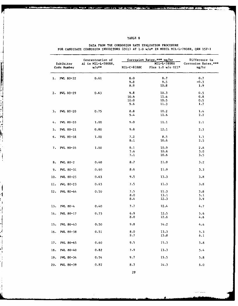
TABLE 8
DATA FROM THE CORROSION RATE EVALUATION PROCEDUREFOR CANDIDATE CORROSION INHIBITORS (CCI) AT 1.0 w/o* IN MOBIL MIL-L-7808H, QRN 15F-1
Concentration of Corrosion Rates,*** mg/hr Difference inInhibitor Al in MIL-L-7808H, MIL-L-7808H Corrosion Rates,***
Code Number W/O** MIL-C-8188C Plus 1.0 W/o CCI* mg/hr
1. PWL 80-32 0.61 8.0 8.7 0.79.8 9.5 -0.38.9 10.8 1.9
2. PWL 80-29 0.63 9.8 10.3 0.5'110.6 11.4 0.8
10.0 10.5 0.59.6 11.3 1.7
3. PWL 80-20 0.75 8.8 10.2 1.4
9.4 11.6 2.2
4. PWL 80-33 1.00 9.0 11.1 2.1
5. PWL 80-21 0.80 9.8 12.1 2.3
6. PWL 80-18 1.00 7.2 8.5 1.38.1 10.6 2.5
7. PWL 80-35 1.00 8.1 10.9 2.87.6 10.6 3.07.1 10.6 3.5
8. PWL 80-2 0.40 8.7 11.9 3.2
9. PWL 80-31 0.60 8.6 11.9 3.3
10. PWL 80-25 0.63 9.5 13.3 3.8
11. PWL 80-23 0.63 7.5 11.3 3.8
$12. PWL 80-64 0.50 7.5 11.3 3.88.0 13.1 5.18.4 12.3 3.9
13. P141 80-4 0.40 7.7 12.4 4.7
14. PWL 80-17 0.75 6.9 12.5 5.68.0 12.6 4.6.115. PWL 80-43 0.50 9.8 14.2 4.4
16. PWL 80-38 0.51 8.0 13.3 5.39.7 15.8 6.1
17. PWL 80-65 0.60 9.5 15.3 5.8
18. PWL 80-40 0.82 7.9 13.3 5.4
19. PWL 80-34 0.54 9.7 15.5 5.8
20. PWL 80-39 0.82 8.3 14.3 6.0
29
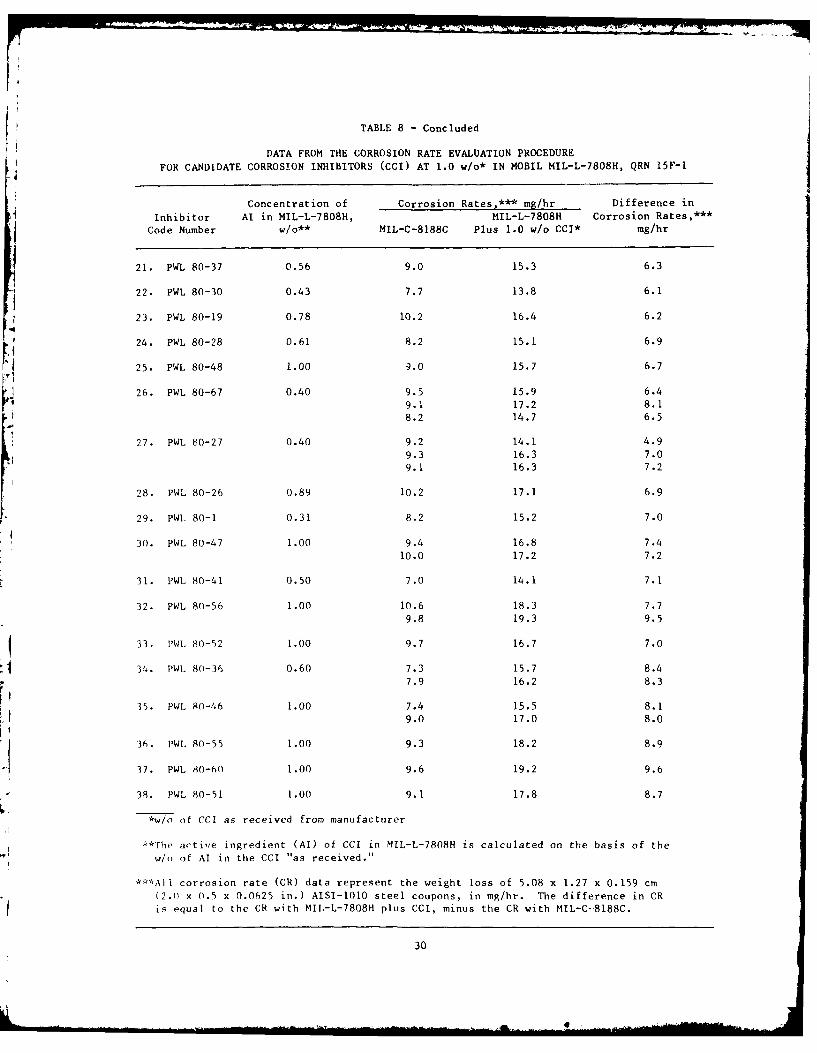
TABLE 8 - Concluded
DATA FROM THE CORROSION RATE EVALUATION PROCEDURE
FOR CANDIDATE CORROSION INHIBITORS CCCI) AT 1.0 w/o* IN MOBIL MIL-L-7808H, QRN 15F-I
Concentration of Corrosion Rates,*** mg/hr Difference in
Inhibitor AI in MIL-L-7808H, MIL-L-7808H Corrosion Rates,***
Code Number w/o** MIL-C-8188C Plus 1.0 w/o CCI* mg/hr
21. PWL 80-37 0.56 9.0 15.3 6.3
22. PWL 80-30 0.43 7.7 13.8 6.1
23. PWL 80-19 0.78 10.2 16.4 6.2
24. PWL 80-28 0.61 8.2 15.1 6.9
25. PWL 80-48 1.00 9.0 15.7 6.7
26. PWL 80-67 0.40 9.5 15.9 6.4
9.1 17.2 8.1
8.2 14.7 6.5
27. PWL 80-27 0.40 9.2 14.1 4.99.3 16.3 7.09.1 16.3 7.2
28. PWL 80-26 0.89 10.2 17.1 6.9
29. PWL 80-1 0.31 8.2 15.2 7.0
30. PWL 80-47 1.00 9.4 16.8 7.4
10.0 17.2 7.2
31. PWL 80-41 0.50 7.0 14.1 7.1
32. PWL 80-56 1.00 10.6 18.3 7.7
9.8 19.3 9.5
433. 1'WI 80-52 1.00 9.7 16.7 7.0
34. PWL 80-36 0.60 7.3 15.7 8.47.9 16.2 8.3
35. PWL 80-46 1.00 7.4 15.5 8.1
9.0 17.0 8.0
'I36. PWL 80-55 1.00 9.3 18.2 8.9
37. PWL 80-60 1.00 9.6 19.2 9.6
38. PWL 80-51 1.00 9.1 17.8 8.7
,*w/o of CCL as received from manufacturer
A'The active ingredient (AI) of CCI in MIL-L-7808H is calculated on the basis of the
w/o of Al in the CCI as received."
***All corrosion rate (CR) data represent the weight loss of 5.08 x 1.27 x 0.159 cm
(2.0 x 0.5 x 0.0625 in.) AISI-1010 steel coupons, in mg/hr. The difference in CR
is equal to the CR with MIL-L-7808H plus CCI, minus the CR with MIL-C-8188C.
30
41I
-F
to preserve the physical and chemical properties of the MIL-L-7808Hoil.
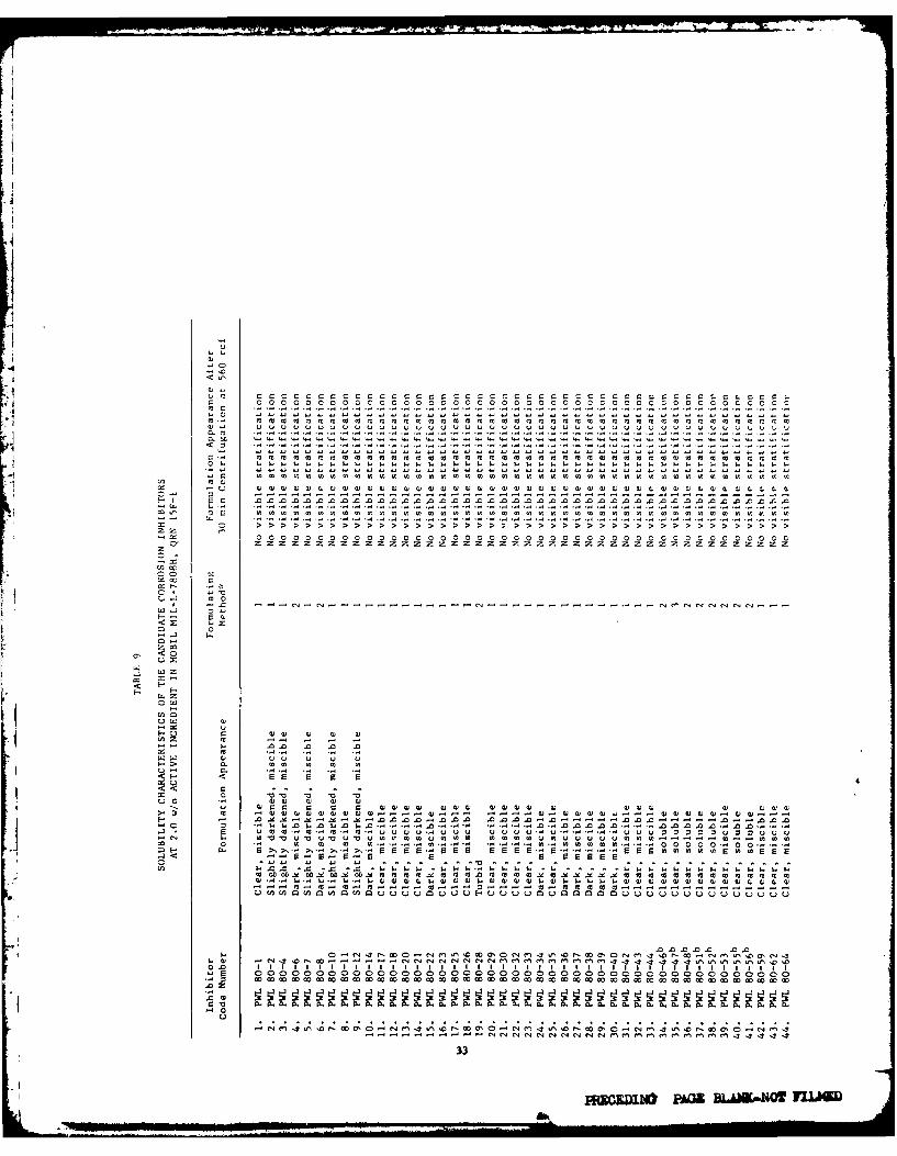
In order to accomplish the evaluation of 67 CCI, a screening testwas developed that involved the sequential elimination of the lessdesirable CCI on the basis of their solubility and corrosion inhibit-ing characteristics. This test matrix provided a means of selectingthe most promising CCI for a more in-depth analysis of their corrosionprotection capabilities at various concentrations, in addition totheir effect on the physical and chemical properties of the baseMIL-L-7808H lubricating oil. After establishing the maximum and mini-mum Al concentrations for this investigation, the initial screening ofthe 67 CCI was performed on the basis of their solubility characteris-tics in MIL-L-7808H oil. Predicated on the importance of eliminatingthe potential for sludge formation during long-term storage of thecorrosion inhibiting engine oil, any candidate formulations whichexhibited measurable sedimentation in the solubility tests were rejec-ted. The oil/inhibitor formulations were blended using a magneticstirring hot plate. Many of the CCI blended easily at room tempera-ture, 250C (770F). Those CCI that were difficult to formulate inthe MIL-L-7808H at room temperature were heated to a maximum tempera-ture of 680C (155 0 F) in conjunction with magnetic stirring. Thistemperature was selected to preclude any thermal degradation of theoil/inhibitor formulation during the blending procedure.
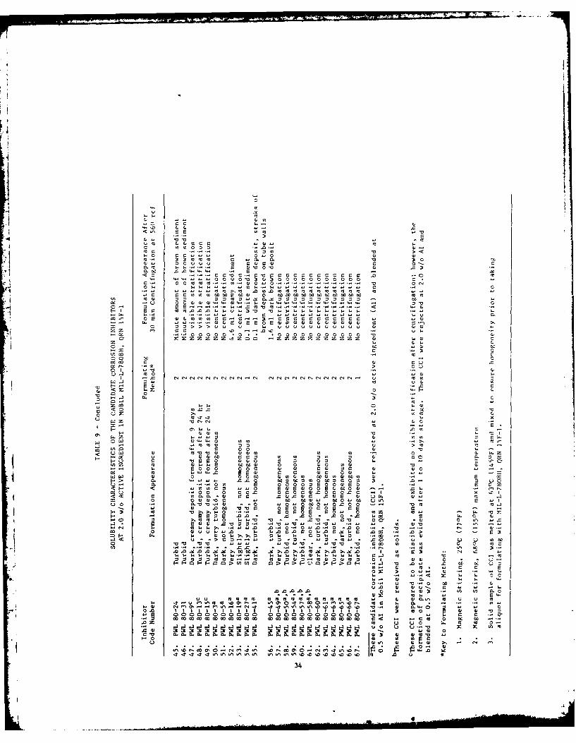
These formulations were subsequently subjected to a 30 min cen-trifugation at 560 rcf. This provided an accelerated method of deter-mining the extent of dissolution of the CCI by concentrating sludges,precipitates, or colloidal suspensions. After recording the appear-ance of each formulation, a 100 ml aliquot was centrifuged for 30min. The results of these tests are presented in Table 9, which givesthe formulation appearance and the extent of sedimentation after thecentrifugation. This table also includes the method employed inblending each CCI with the MIL-L-7808H oil.
Of the 67 CCI, 21 were found to be immiscible or insoluble at2.0 w/o Al. The CCI that did not result in homogeneous solutionsafter 30 min of magnetic stirring at 680C were rejected without cen-trifugation. Three CCI exhibited no visible stratification after cen-
trifugation, but showed significant sedimentation during room tempera-ture storage for 1 to 10 days. Therefore, predicated on the impor-tance of eliminating the potential for sludge formation in the corro-sion inhibiting oil, these CCI were rejected at 2.0 w/o Al. Thesuperscripts in Table 9 indicate which CCI were rejected in this phaseof the screening test series.
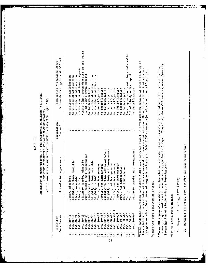
The 21 CCI that were immiscible at the maximum concentration of2.0 w/o Al were subsequently evaluated at the minimum concentration of0.5 w/o Al. These CCI were formulated with MIL-L-7808H using the pro-cedure previously described for the miscibility tests. The formula-tions were then centrifuged and evaluated on the basis of sedimenta-tion during centrifugation. The data generated in these tests is pre-sented in Table 10. Of the 21 CCI assessed at 0.5 w/o AI, 16 werefound to be immiscible. Consequently, these 16 CCI were rejected from
31
IIT 2
I ccaaccccccccc0 00 0
.2 2-.-22 2. 2- -. 040 2 C 0 0 . C
U 1UUU1 1
<-'C ~ ~ ~ ~ ~ ~ Z ZOO OO O O O ZCO OO O OO O O Z, "IOCZC Z
ES 0 0 00 0o 00(0 0 0 0 0 0 0 0 0 0 0(0 0 s0 0 0 0 0 0 0 0 00 00 0 0 0 0(0 0 0 0 0
Cd
0-- - - - - - - --- - - - - --
0
<z -w 0
>3 0.
< . s . E s Es 9
u0z 4)4 4
.4 M5 (0 0u v u . . - 0.Es 2 E 22 ..
474.Z .r **C004E11 E E.. E s E ssssssss
.000.. .0.
M I I D I D a, M I 14 I CI 0I 1: I I I I I I I I I I
3
EPICED1N ?AMl BLAW"-N0 YJIJSD
ca 0
-CL 0. u~3'a, 00 u ) ww- w C
a. v. .0ar ;
0 '( 0 0 a .I t 0r 0000 mm0c w-- '0' 0
303)c cw m0 F-1w((. 2 0 0)00 00 cc.00 0 L c o0
.0 .- r :
00a C* 0.01) X: 1 F-SJ'3.. z z z z z z z z0z.M
00tU3 -o 00c3 2)~". 3'.- . )~ ).) -3').3~1.-3'0
2 .- . . 0 ' 3.0 ' . . ~~3*. - 3*'**.44 44..)). .4JJJ.AJ . .
V" 00 -3 C.0. .
0 ~ C4 Iz
C:3 0 0)0Q3F .. ). 000 z4
0, wF w4~ 0 3
0 r ) Q c-. jF)'4J'J-. ~ ~ ~ N N N N .CN. w a, 0
F44 >3 -. a 0 'w '
H.- 03 r=4 t
<z 0 0 C.
T.- a)'C3..$0 00 '3 . .3 0no 0 ~ (Dvu 09:4c 0
0 0 vv c- 00 -0 0x %3( >1. >100-Y>. > -
0. 0 00a3 0 F..
HO ~ ~ ~ ~ L 0c20o)) 0- 0M.-3) "0
3(333~~~ 13 3)F1) 333) 0 0 30 ' 0 0. '000 002000 000 3) 3) 03) 000 3) r) .
0. 9X 0 . 4w .C 0.00 9 3 03 ( 03 0 0 3' 4) 4 0 0
0. -.. 103 2 0000 003) 0 . 033<H~~l )-'D30 D 100 3 0 m. 0.
*000 00.0 000~3 . 0 00 3 3 .
I p jjlll lll
$41 w) 0 0
cc4 C: c .1 ) w 1"-W44w4- 0.4 0 040 a000.44
ca m 04-4: c0 0
oa cammOtw w)4 m0 m W-
14.4 4 44 0 0 .4- 0 44 w W
-0 S 1 4* 0000 0 A 00 0000 0 x 4- 0-4C0n ". r--- $4 -,-4 -. 4 4 .0 00 w -.. ., . .. 0 w 4
* ~ ~ ~ ~ c w m4- w4 m4 44 0 0 m4 m4 0 4. 44M W- W~4 .0-- to44- (n0" w.to 00w0w 0 w4 44 0o4)bo w
W4 W4 W44 0 to w4 4 w c4 44 LW 44"4 '4" "4 .4 4.4 "-W 14 0n 0 k-4 0 04)$
cJ 0 E .- 1 .0.0$o W W W W W W W W -' 4 4-U 4 Q 00 40 u
= 41r= W.444. -4444d)0444440 W44 WJ.- W 4a.4$4) :wIV
0 0 0 040 00 0 0)4'44-'4444-4- 044- 0 0
Zx ZZZZZZZ 0 orn <' 00 2404 )
0 0d ' 0"
iE-004) w.
0000>- 4 $4
C.)O.-~~ 0w44) 4.
m 0 -444
w 00
W ZW '-0
V0 0 4-4 $
0w 0 020..00 0 m).4 .0 $4 0
0 00 0 4)V 4) 0.$
"4, ) 0 w)4) 4) 1-4 ) Fw 44W w4) ( 0 0 10 w 04
'-4 -4 o - -w4 - E2 w 41 00.$4 .0 .0 to .0 4444 004444440 0 a)01 044 w2AF
44 ".o -404-4 z 0 0 0 0 H 0 -4 01- 0a> 4V) 0 20 0 0 004 4 0~- 000 2
Z0. U) 440 044) )4-44-44)4w4z00 4.1 -'.4 "4...~0- ~ 0. -,4 .4 0)-4 =0 000=00z00 0 - 2 r= " 0 "W 2 02E 4 )0 04w)w)w)w44 r 0 Q- .1i m4 0 m
4.44) 00 00 000w000 .X. z4 u2=0 c '0 00'- 0 0 '0 0 044) W . - m .4 4)0
09 0 m c: W'4' 0u a 5 E -o2220E 0 ' 0 44E W3t .4 .. 0- .0 -0 00.0 4CC 0 C C02 $4 1-)00 0 cc0 r. 0
Ha 44 $4"4.0 4 '0 C4$ $4 1 0 W0 w- 0.4 m 4-444 0 Lr%W, z4 z4 :3 0 0 .4 z0 444-40 44444-.0. 0 4-44 r= 44 4.' '4
U) 0A -444 ".0 41 4..0 0 . .0 00 44j -- 4 r- w44 w'4 0 . .0 $4 0 0 0 0 044 .0 U444 0 04>
~~ H 0 -4 4 44 '- . - 0 -1 to 0 0M4 . .
~4 44 40 0.4 000 M 4 004 0.
CA4m 04m4m 00. cu0w00..0 000. 04 00 "-4 44 -.40 .. c4 10CU..4) 4) W Q4)..4 W44$W.-. W44 $4 W4$44 000 r.W 4 .00U0 "0
p 01-W-A- ,4 uw4) =0 00 00
0 > .' 00 4
v).r4 $4 $
.00.. 4) $4 $4w 4 "4 41-~~C 2. - )-444 0 "4
v Co M 144 14 14 M4 0 M4 CO 4440 .4 4) 4) 44 u u$4~-'O 44 um U to0 m In 10 (4A' r--0 cc4 C w4 $4 0>10 r '
$44) Ln '04 4) W0. tnLn4I 01 0' f4) 0 44 4
0 .0 11 1 1 111 1 1 1 1 1 1 =.4)4 4 .- 4 2)
-. 0~000 4 4-4 M 0 00 0
VO 44 C.) U. 0 $4 44 X: 10) 0-4 0. )& 0
c V) Al 911 4)A 4CO0 4A4NA dO WA A 49 A 4> 44 "10 0 4 w w4)4)
-4- -4- -4' '0 44 c0 w
35
the investigation of single additive formulations based on theirimmiscibility at the minimum AI concentration. The superscripts in
Table 10 indicate which CCI were rejected.
The next phase of the screening test series involved evaluatingthe relative corrosion inhibiting capabilities of the 46 CCI that weremiscible at 2.0 w/o AI. The corrosion tests used to assess theseoil/inhibitor formulations were performed according to the CREPdefined in Appendix A and the Sequential Sampling Plan (SSP) definedin Appendix B. These tests defined the corrosion protection providedby a thin film of each formulation, relative to the protection pro-vided by MIL-C-8188C. The SSP was developed to expedite the elimina-tion of the less effective CCI with 95% confidence.
The SSP was predicated on the results of 48 corrosion tests con-ducted in accordance with the CREP, using coupons protected by
MIL-C-8188C. The mean corrosion rate for the specimens was 8.76 mg/hrwith a standard deviation of +0.99 mg/hr. Based on these data, atruncated SSP was constructed which allowed for an early terminationof testing and provided a means of determining the relative corrosionprotection of an oil/inhibitor formulation in a maximum of threetests. Using the SSP in conjunction with the CREP, a maximum of threetests was required to determine whether a formulation of 2.0 w/o AI ofCCI was at least as effective as, or less effective than, MIL-C-8188C.
This SSP provided an excellent means of accelerating the elimina-tion of the less effective CCI with very reasonable levels of confi-dence. The acceptable quality level of this plan was 8.76 mg/hr andhad an alpha risk of 0.05 associated with it. This indicates that 5%of the oil/inhibitor formulations rejected as less effective thanMIL-C-8188C may have resulted, through further testing, in mean cor-rosion rates that were less than 8.76 mg/hr. In other words, the lesseffective CCI were rejected with 95% confidence. The rejectable qual-ity level of the plan was 10 mg/hr and had a beta risk of 0.37 associ-ated with it. This suggests that 37% of the formulations accepted mayactually have had a mean corrosion rate greater than 10 mg/hr. Alarger beta risk level was accepted because subsequent tests were tobe performed on the most promising CCI to verify their effectiveness.The major objective of the plan was the elimination of all inferiorCCI, consequently reducing the number to a maximum of 13 of the mostpromising.
The data generated in the corrosion tests conducted at 2.0 w/o AIof CCI are presented in Table 11, which lists the corrosion rates ofmetal coupons protected by a thin film 3 of MIL-L-7808H with CCI,coupons protected by a thin film of MIL-C-8188C, and the differencebetween these two corrosion rates for each test.
3. The oil film thickness on the coupons was approximately 13microns (0.5 mil), as calculated according to the formulaprovided in Aerospace Material Specification (AMS) 3065D,15 March 1966, Item 4.2.1.4.1.
37
PRECE"J ft=E BhIL-NOI FlW
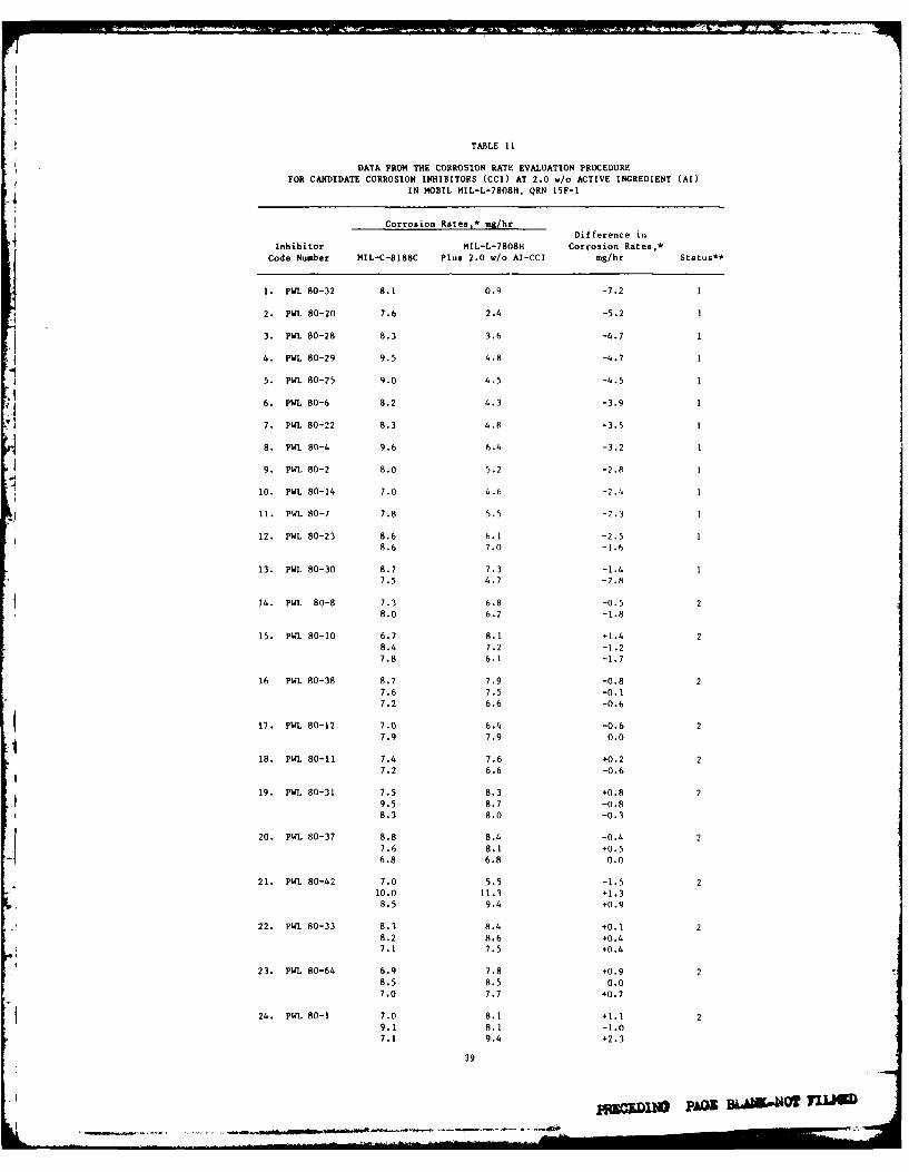
TABLE 11
DATA FROM THE CORROSION RATE EVALUATION PROCEDURE
FOR CANDIDATE CORROSION INHIBITORS (CCI) AT 2.0 w/o ACTIVE INGREDIENT (Al)IN MOBIL MI1.-1-7808H, QRN 15F-i
Corrosion Rates,* isa/hrDifference in
Inhibitor MIL-L-7808H Corrosion Rates,*Code Number MIL-C-8188C Plus 2.0 w./o AI-CCI mg/hr Status**
1. P141 80-32 8.1 0.9 -7.2 1
42. PWL1 80-20 7.6 2.4 -5.2 1
3. PWL1 80-28 8.3 3.6 -4.7 1
4. PUL 80-29 9.5 4.8 -4.71
5. PWL 80-25 9.0 4.5 -4.5 1
A6. PWL 80-6 8.2 4.3 -3.9
7. P141 80-22 8.3 4.8 -3.5 1
S. PWi. 80-4 9.6 6.4 -3.2 1
9. PWL 80-2 8.0 5.2 -2.A 1
10. PWL 80-14 7.0 4.6 -2.4 1
411. P141 80-7 7.8 5.5 -2.3 1
12. PWL 80-23 8.6 6.1 -2.5 18.6 7.0 -1.6
13. P141 80-30 8.7 7.3 -1.4 17.5 4.7 -2.8
14. PWL1 80-8 7.3 6.8 -0.5 28.0 6.2 -1.8
15. P141 80-10 6.7 8.1 +1.4 28.4 7.2 -1.27.8 6.1 -1.7
16 P141 80-38 8.7 7.9 -0.8 27.6 7.5 -0.17.2 6.6 -0.6
417. PWL1 80-12 7.0 6.4 -0.6 2
18. P141 80-11 7.4 7.6 +0.2 27.2 6.6 -0.6
19. P141 80-31 7.5 8.3 +0.8 29.5 8.7 -0.88.3 8.0 -0.3
20. P141 80-37 8.8 8.4 -0.4 2-17.6 8.1 +0.56.8 6.8 0.0
21. P141 80-42 7.0 5.5 -1.5 210.0 11.3 +1.3
8.5 9.4 +0.9
22. P141 80-33 8.3 8.4 +0.1 28.2 8.6 +0.47.1 7.5 +0.4
23. P141 80-64 6.9 7.8 +0.9 28.5 8.5 0.0
7.0 7.7 +0.7
24. P141 80-1 7.0 8.1 +1.1 29.1 8.1 -1.07.1 9.4 +2.3
39
-~AG - -.--- OT--L. -
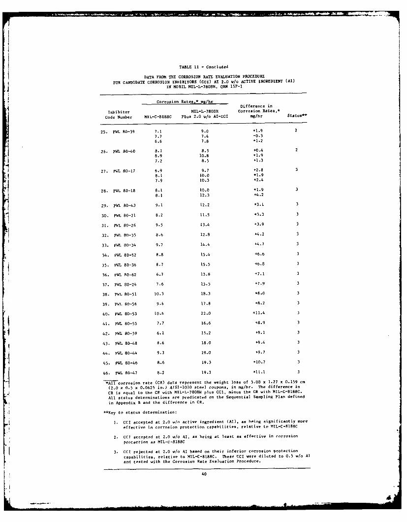
TABLE 11 - Concluded
DATA FROM THE CORROSION RATE EVALUATION PROCEDURE
FOR CANDIDATE CORROSION INHIBITORS (CCI) AT 2.0 w/o ACTIVE INGREDIENT (AI)IN MOBIL MIL-L-7808H, QRN 15F-i
Corrosion Rates* mg/hr4 Difference in
Inhibitor MIL-L-7808H Corrosion Rates,*
Code Number MIL-C-8188C Plus 2.0 w/o AI-CCI mg/hr Status**
25. PWL 80-39 7.1 9.0 +1.9 2
7.7 7.4 -0.3
6.6 7.8 +1.2
26. PWL 80-40 8.1 8.5 +0.4 2
8.9 10.8 +1.9
7.2 8.5 +1.3
27. PWL 80-17 6.9 9.7 +2.8 3
8.1 10.0 +1.9
7.9 10.3 +2.4
28. PWL 80-18 8.1 10.0 +1.9 3
8.1 12.3 +4.2
29. PML 80-43 9.1 12.2 +3.1 3
30. PWL 80-21 8.2 11.5 +3.3 3
31. PWL 80-26 9.5 13.4 +3.9 3
32. PWL 80-35 8.6 12.8 +4.2 3
33. PWL 80-34 9.7 14.4 +4.7 3
34. PWL 80-52 8.8 15.4 +6.6 3
35. PWL 80-36 8.7 15.5 +6.8 3
36. PWL 80-62 6.7 13.8 +7.1 3
37. PWL 80-24 7.6 15.5 +7.9 3
38. PWL 80-51 10.3 18.3 +8.0 3
39. PlL 80-56 9.6 17.8 +8.2 3
40. PWL 80-53 10.6 22.0 +11.4 3
41. PWL 80-55 7.7 16.6 +8.9 3
42. PWL 80-59 6.1 15.2 +9.1 3
43. PWL 80-48 8.6 18.0 +9.4 3
44. PWL 80-44 9.3 19.0 +9.7 3
45. PWL 80-46 8.6 19.3 +10.7 3
46. PWL 80-47 8.2 19.3 +11.1 3
*All corrosion rate (CR) data represent the weight loss of 5.08 x 1.27 x 0.159 cm
(2.0 x 0.5 x 0.0625 in.) AISI-1OO steel coupons, in mg/hr. The difference in
CR is equal to the CR with MIL-L-7808H plus CCI, minus the CR with MIL-C-8188C.
All status determinations are predicated on the Sequential Sampling Plan defined
in Appendix B and the difference in CR.
**Key to status determination:
I. CCI accepted at 2.0 w/o active ingredient (Al), as being significantly more
effective in corrosion protection capabilities, relative to MIL-C-8188C
2. CCI accepted at 2.0 w/o Al, as being at least as effective in corrosion
protection as MIL-C-8188C
3. CCI rejected at 2.0 w/o Al based on their inferior corrosion protection
capabilities, relative to MIL-C-8188C. These CCI were diluted to 0.5 w/o AI
and tested with the Corrosion Rate Evaluation Procedure.
40
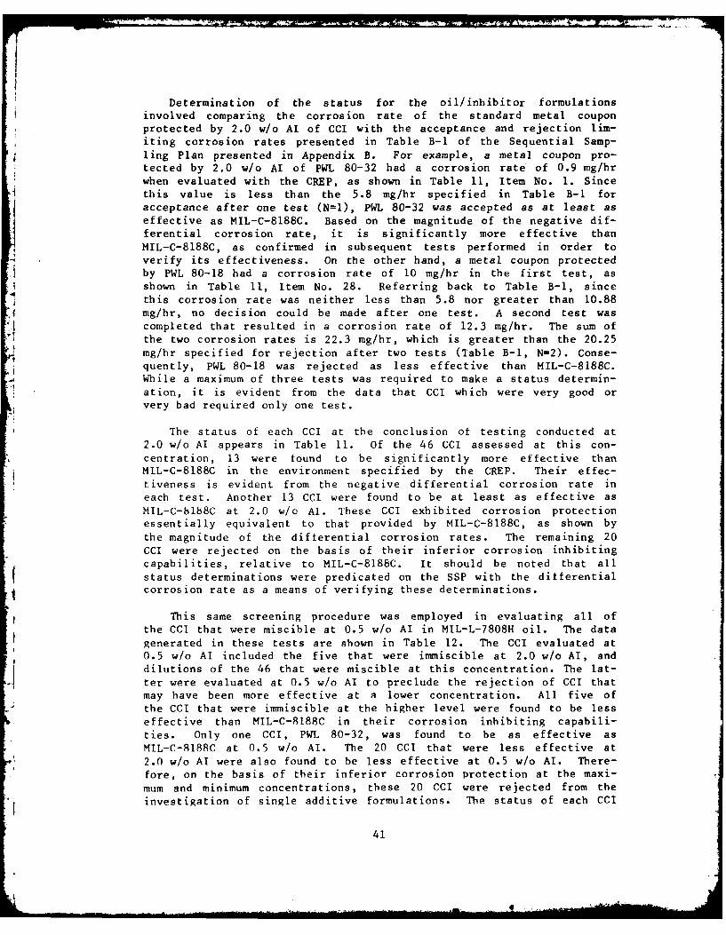
Determination of the status for the oil/inhibitor formulationsinvolved comparing the corrosion rate of the standard metal couponprotected by 2.0 w/o AI of CCI with the acceptance and rejection lim-iting corrosion rates presented in Table B-I of the Sequential Samp-ling Plan presented in Appendix B. For example, a metal coupon pro-tected by 2.0 w/o AI of PWL 80-32 had a corrosion rate of 0.9 mg/hrwhen evaluated with the CREP, as shown in Table 11, Item No. 1. Sincethis value is less than the 5.8 mg/hr specified in Table B-i foracceptance after one test (N=I), PWL 80-32 was accepted as at least aseffective as MIL-C-8188C. Based on the magnitude of the negative dif-ferential corrosion rate, it is significantly more effective thanMIL-C-8188C, as confirmed in subsequent tests performed in order toverify its effectiveness. On the other hand, a metal coupon protectedby PWL 80-18 had a corrosion rate of 10 mg/hr in the first test, asshown in Table 11, Item No. 28. Referring back to Table B-l, sincethis corrosion rate was neither less than 5.8 nor greater than 10.88mg/hr, no decision could be made after one test. A second test wascompleted that resulted in a corrosion rate of 12.3 mg/hr. The sum ofthe two corrosion rates is 22.3 mg/hr, which is greater than the 20.25mg/hr specified for rejection after two tests (Table B-i, N=2). Conse-quently, PWL 80-18 was rejected as less effective than MIL-C-8188C.While a maximum of three tests was required to make a status determin-ation, it is evident from the data that CCI which were very good orvery bad required only one test.
The status of each CCI at the conclusion of testing conducted at2.0 w/o Al appears in Table 11. Of the 46 CCI assessed at this con-centration, 13 were found to be significantly more effective thanMIL-C-8188C in the environment specified by the CREP. Their effec-tiveness is evident from the negative differential corrosion rate ineach test. Another 13 CCI were found to be at least as effective asMIL-C-188C at 2.0 w/o Al. These CCI exhibited corrosion protectionessentially equivalent to that provided by MIL-C-8188C, as shown bythe magnitude of the differential corrosion rates. The remaining 20CCI were rejected on the basis of their inferior corrosion inhibitingcapabilities, relative to MIL-C-8188C. It should be noted that allstatus determinations were predicated on the SSP with the differentialcorrosion rate as a means of verifying these determinations.
This same screening procedure was employed in evaluating all ofthe CCI that were miscible at 0.5 w/o AI in MIL-L-7808H oil. The datagenerated in these tests are shown in Table 12. The CCI evaluated at0.5 w/o Al included the five that were immiscible at 2.0 w/o AI, anddilutions of the 46 that were miscible at this concentration. The lat-ter were evaluated at 0.5 w/o AI to preclude the rejection of CCI thatmay have been more effective at a lower concentration. All five ofthe CCI that were immiscible at the higher level were found to be lesseffective than MIL-C-8188C in their corrosion inhibiting capabili-ties. Only one CCI, PWL 80-32, was found to be as effective asMIL-C-8188C at 0.5 w/o Al. The 20 CCI that were less effective at2.0 w/o Al were also found to be less effective at 0.5 w/o Al. There-fore, on the basis of their inferior corrosion protection at the maxi-mum and minimum concentrations, these 20 CCI were rejected from the
investigation of single additive formulations. The status of each CCI
41
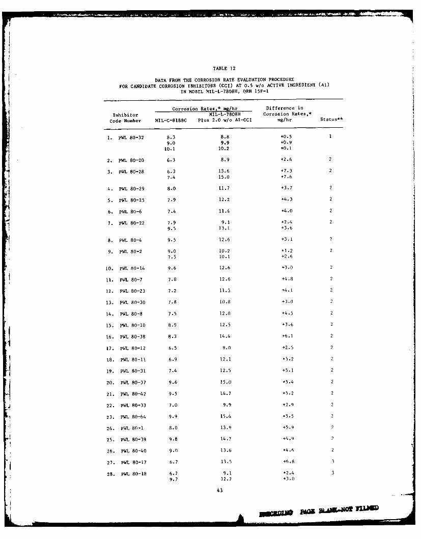
TABLE 12
DATA FROM THE CORROSION RATE EVALUATION PROCEDURE
FOR CANDIDATE CORROSION INHIBITORS (CCI) AT 0.5 w/o ACTIVE INGREDIENT (AI)
IN MOBIL MIL-L-7808H, QRN 15F-I
Corrosion Rates,* rag/hr.. Difference in
Inhibitor MIL-L-7808H Corrosion Rates,*
Code Number MIL-C-8188C Plus 2.0 w/o AI-CCI mg/hr Status**
1. pWL 80-32 8.3 8.8 +0.5 19.0 9.9 +0.9
10.1 10.2 +0.1
2. PWL 80-20 6.3 8.9 +2.6 2
3. PWL 80-28 6.3 13.6 +7.3 2
7.4 15.0 +7.6
4. PWL 80-29 8.0 11.7 +3.7 2
5. PWL 80-25 7.9 12.2 +4.3 2
6. PWL 80-6 7.4 11.4 +4.0 2
7. PWL 80-22 7.9 9.1 +2.4 2
9.5 13.1 +3.6
8. PWL 80-4 9.5 12.6 +3.1 2
9. PWL 80-2 9.0 10.2 +1.2 27.5 10.1 +2.6
10. PWL 80-14 9.6 12.6 +3.0 2
11. PWL 80-7 7.8 12.6 +4.8 2
12. PWL 80-23 7.2 11.3 +4.1 2
13. PWL 80-30 7.8 10.8 +3.0 2
14. PWL 80-8 7.5 12.0 +4.5 2
15. PWL 80-10 8.9 12.5 +3.6 2
16. PWL 80-38 8.3 14.4 +6.1 2
17. PWL 80-12 6.5 9.0 +2.5 2
18. PWL 80-11 6.9 12.1 +5.2 2
19. PWL 80-31 7.4 12.5 +5.1 2
20. PWL 80-37 9.6 15.0 +5.4 2
21. PWL 80-42 9.5 14.7 +5.2 2
22. PWL 80-33 7.0 9.9 +2.9 2
23. PWL 80-64 9.9 15.4 +5.5 2
24. PWL 80-1 8.0 13.9 +5.9 2
25. PWL 80-39 9.8 14.7 +4.9 2
26. PWL 80-40 9.0 13.6 +4.6 2
27. PWL 80-17 6.7 13.5 +6.8 3
28. PWL 80-18 6.7 9.1 +2.4 39.7 12.7 +3.0
43
-~PA NQ3A- 1U
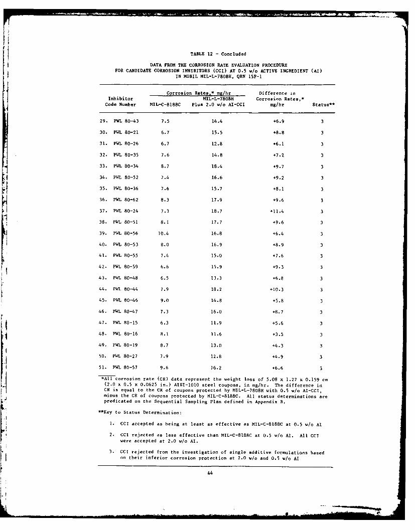
TABLE 12 - Concluded
DATA FROM THE CORROSION RATE EVALUATION PROCEDUREFOR CANDIDATE CORROSION INHIBITORS (CCI) AT 0.5 w/o ACTIVE INGREDIENT (AI)
IN MOBIL MIL-L-7808H, QRN 15F-I
Corrosion Rates,* mg/hr Difference inInhibitor MIL-L-7808H Corrosion Rates,*Code Number MIL-C-8188C Plus 2.0 w/o AI-CCI mg/hr Status**
29. PWL 80-43 7.5 14.4 +6.9 3
30. PWL 80-21 6.7 15.5 +8.8 3
31. PWL 80-26 6.7 12.8 +6.1 3
32. PWL 80-35 7.6 14.8 +7.2 3
33. PWL 80-34 8.7 18.4 +9.7 3
34. PWL 80-52 7.4 16.6 +9.2 3
35. PWL 80-36 7.6 15.7 +8.1 3
36. PWL 80-62 8.3 17.9 +9.6 3
37. PWL 80-24 7.3 18.7 +11.4 3
38. PWL 80-51 8.1 17.7 +9.6 3
39. PWL 80-56 10.4 16.8 +6.4 3
40. PWL 80-53 8.0 16.9 +8.9 3
41. PWL 80-55 7.4 15.0 +7.6 3
42. PWL 80-59 6.6 15.9 +9.3 3
43. PWL 80-48 6.5 13.3 +6.8 3
44. PWL 80-44 7.9 18.2 +10.3 3
45. PWL 80-46 9.0 14.8 +5.8 3
46. PWL 80-47 7.3 16.0 +8.7 3
47. PWL 80-15 6.3 11.9 +5.6 3
48. PWL 80-16 8.1 11.6 +3.5 3
49. PWL 80-19 8.7 13.0 +4.3 3
50. PWL 80-27 7.9 12.8 +4.9 3
51. PWL 80-57 9.6 16.2 +6.6 3
*All corrosion rate (CR) data represent the weight loss of 5.08 x 1.27 x 0.159 cm
(2.0 x 0.5 x 0.0625 in.) AISI-1OO steel coupons, in mg/hr. The difference inCR is equal to the CR of coupons protected by MIL-L-7808H with 0.5 w/o AI-CCI,minus the CR of coupons protected by MIL-C-8188C. All status determinations arepredicated on the Sequential Sampling Plan defined in Appendix B.
**Key to Status Determination:
1. CCI accepted as being at least as effective as MIL-C-8188C at 0.5 w/o Al
2. CCI rejected as less effective than MIL-C-8188C at 0.5 w/o Al. All CCI
were accepted at 2.0 w/o Al.
3. CCI rejected from the investigation of single additive formulations based
on their inferior corrosion protection at 2.0 w/o and 0.5 w/o Al
44

at the conclusion of this phase of the investigation is indicated inTable 12.
The five CCI that were immiscible at 2.0 w/o Al and less effective
at 0.5 w/o AI were subsequently evaluated at 1.0 w/o AI. Two of these,PWL 80-15 and 80-57, were immiscible at 1.0 w/o Al and were thereforerejected from this investigation. PWL 80-16 and 80-19 were miscible,but were rejected on the basis of their inferior corrosion protectionat 1.0 w/o AI. PWL 80-27, however, was found to be miscible and atleast as effective as MIL-C-8188C at a 1.0 w/o AI concentration. Fig-ure 1 summarizes the screening test matrix and the results of screen-ing 67 CCI on the basis of their solubility characteristics and cor-
rosion protection capabilities in the environment dictated by the
CREP. Table 13 is a key to the superscripts and specifies which CCIwere accepted or rejected at each phase of the test series. Of theinitial 67 CCI, 40 were rejected on the basis of their immiscibilityor inferior corrosion inhibition relative to MIL-C-8188C.
The selection of the 13 most promising CCI was predicated on thenegative differential corrosion rates in tests performed with theCREP. Triplicate tests were performed on formulations containing2.0 w/o Al of these CCI in order to verify their effectiveness. The
data generated in these tests are shown in Table 14. As shown in thistable, the resulting differences in corrosion rates exhibited good
repeatability for most of the formulations. Some scatter exists inthe data for inhibitor PWL 80-28, but this oil/inhibitor was more
effective than MIL-C-8188C in all tests. Three of the CCI (PWL 80-20,80-29, and 80-32) exhibited excellent corrosion protection as shown bythe relatively low magnitude of corrosion rates on metal coupons pro-
tected by these CCI. The data generated in these tests clearly veri-fied preliminary determinations made on the protective capabilities of
these 13 CCI.
It is interesting to note that of the 26 CCI accepted, 14 weremetal sulfonates. Calcium sulfonate derivatives were very effectiveinhibitors in the environment of the CREP. Of the 13 most promisingCCI, PWL 80-2, 80-4, 80-7, 80-14, and 80-30 are all calcium sulfo-nates. In a like manner, alkyl succinic acids and their derivatives(PWL 80-23, 80-25, 80-28, 80-29, and 80-32) were very tenacious inhib-
itors in this environment. For example, tests conducted with PWL80-32 resulted in corrosion only on the edges of the coupons after onehour in the acidic atmosphere.
These results agree with those of Zisman (References 4 and 5)based on assessments made with the Turbine Oil Rusting Test
(AST D-665). The effectiveness of the acids is believed to be caused
by the ability of the hydrogen in the acid to coordinate with elec-trons on the surface of the test specimens. The tenacity of succinic
acid may then be due to the fact that, being dibasic, it has twice theadsorption capacity of a monobasic acid. An interesting conclusiondrawn from Zisman's work was that aliphatic alcohols are less effec-tive on a concentration basis than the homologous primary amines andare much less effective than the homologous acids. The fundamentaldifference is the much shorter average lifetime of adsorption at the
45
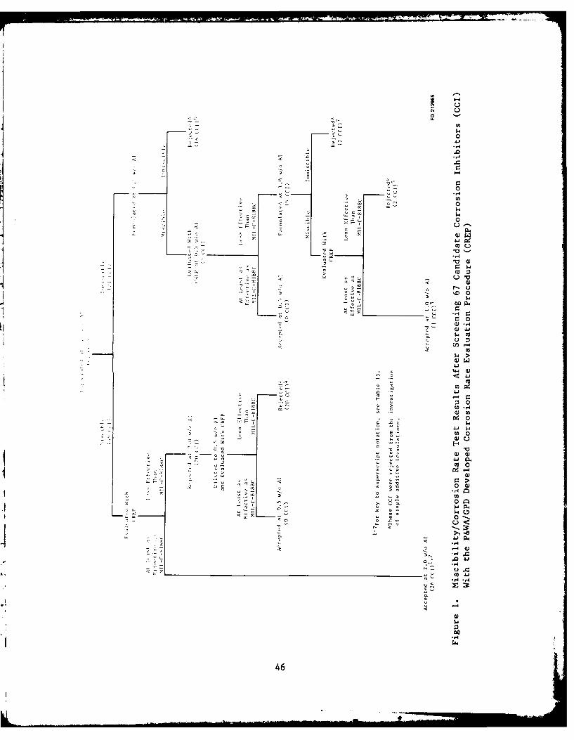
0
0
'-40
4 -4
-c
ac
>:30
4140V)0
EQ-4
va 0
Q)
0 )-,4 IM
04
a, -'-4
00
46
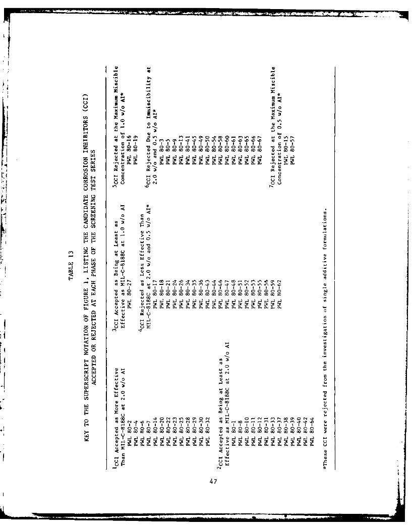
0 ..40
Flo.4
Uj 43
-4 44 w 4
0o 4, 00 43. nL N .w0 ML N A n
4-4 4-4 43QO0 4-,4 0O
3:o 3u. 3r ~ 0 ~ f t nt3 :333 33 4) :r. :r
0-4. @.4~43 .4fQ 4 .j 0 u1 1 1 1 1 1 1 C4Iu I
0 U 00 0 0 0 0 000Q 0
1-0-4 c4
to, 0 0 0
<-4 &4 4) 4
.440
434 0--3 (-34 m
-4 - ca~ cu- " 4 4 C4 M M M 4 4 , - n - - - -wo .~
w~L aco£z~ WW00
03 en0 -
t-44. 3
E4)
<U ~0
oj0.- ~ -
c 00
w -4
0 cc 4)
053 54>U530"4
H-Ito
L) 4
H -. 1'~~I 9 11111111 111 t~l 47
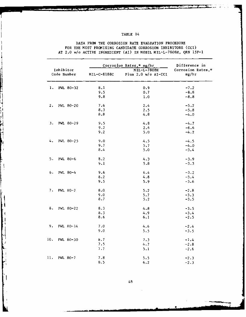
TABLE 14
DATA FROM THE CORROSION RATE EVALUATION PROCEDUREFOR THE MOST PRCMISING CANDIDATE CORROSION INHIBITORS (CCI)
AT 2.0 w/o ACTIVE INGREDIENT (AI) IN MOBIL MIL-L-7808H, QRN 15F-i
Corrosion Rates,* mg/hr Difference inInhibitor MIL-L-7808H Corrosion Rates,*
Code Number MIL-C-8188C Plus 2.0 w/o AI-CCI mg/hr
1. PWL 80-32 8.1 0.9 -7.29.5 0.7 -8.89.8 1.0 -8.8
2. PWL 80-20 7.6 2.4 -5.28.3 2.5 -5.88.8 4.8 -4.0
3. PWL 80-29 9.5 4.8 -4.79.2 2.6 -6.69.2 5.0 -4.2
4. PWL 80-25 9.0 4.5 -4.59.7 5.7 -4.08.4 5.0 -3.4
5. PWL 80-6 8.2 4.3 -3.99.1 5.8 -3.3
6. PWL 80-4 9.6 6.4 -3.28.2 4.8 -3.49.5 5.9 -3.6
7. PWL 80-2 8.0 5.2 -2.89.0 5.7 -3.38.7 5.2 -3.5
8. PWL 80-22 8.3 4.8 -3.58.3 4.9 -3.4
8.6 6.1 -2.5
9. PWL 80-14 7.0 4.6 -2.4
9.0 5.5 -3.5
10. PWL 80-30 8.7 7.3 -1.47.5 4.7 -2.87.7 5.1 -2.6
11. PWL 80-7 7.8 5.5 -2.38.5 6.2 -2.3
48
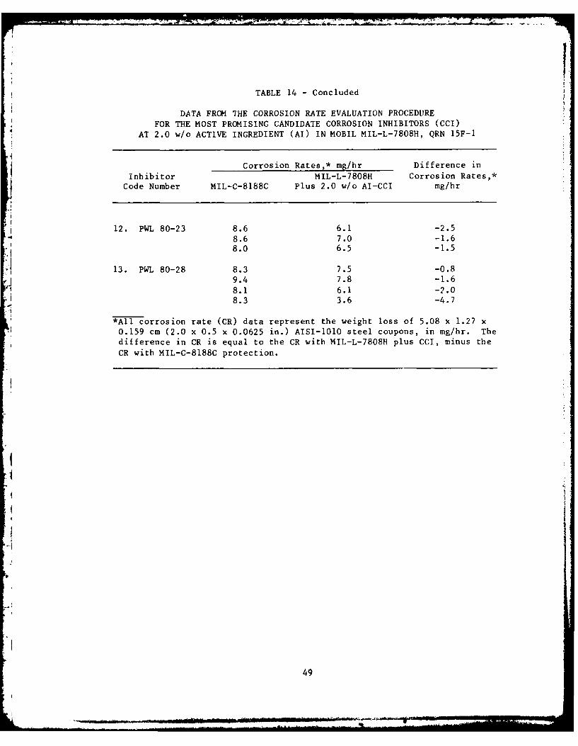
TABLE 14 - Concluded
DATA FROM THE CORROSION RATE EVALUATION PROCEDUREFOR THE MOST PROMISING CANDIDATE CORROSION INHIBITORS (CCI)
AT 2.0 w/o ACTIVE INGREDIENT (AI) IN MOBIL MIL-L-7808H, QRN 15F-1
Corrosion Rates,* mg/hr Difference in
Inhibitor MIL-L-7808H Corrosion Rates,*Code Number MIL-C-8188C Plus 2.0 w/o AI-CCI mg/hr
12. PWL 80-23 8.6 6.1 -2.5
8.6 7.0 -1.68.0 6.5 -1.5
13. PWL 80-28 8.3 7.5 -0.89.4 7.8 -1.6
8.1 6.1 -2.0
8.3 3.6 -4.7
*All corrosion rate (CR) data represent the weight loss of 5.08 x 1.27 x0.159 cm (2.0 x 0.5 x 0.0625 in.) AISI-1010 steel coupons, in mg/hr. The
difference in CR is equal to the CR with MIL-L-7808H plus CCI, minus the
CR with MIL-C-8188C protection.
.1
49
oil-metal interface of the alcohol molecules as compared to the cor-responding amines or acids (Reference 6).
Preliminary evaluations were performed to determine the effect of
2.0 w/o AI of CCI on the physical and chemical properties ofMIL-L-78081i oil. Several of the oil/inhibitor formulations failed to
conform to the MIL-L-780H specification requirements for flash point,
foaming, and/or total acid number (TAN). Since the MIL-L-7808H withoutCCI was in full conformance with the specification requirements, the
nonconformance of the oil/inhibitor formulations was fully attribu-
table to the CCI. Consequently, the most promising inhibitors wereevaluated at lower concentrations in an effort to establish the lowestconcentration of each CCI that could exhibit corrosion protection
greater than that of MIL-C-188C.
Each of the 13 most promising CCI was evaluated at 2.0, 1.5, 1.0,
and 0.5 w/o AT in MIL-L-7808H using the CREP. The SSP was employed todetermine the status of the CCI at each concentration. The results of
these evaluations are presented in Table 15. The table also lists thestatus of the CCI at each AT concentration. As noted in the table,all of the CCI were found to be at least as effective as MIL-C-818RC
at 2.0 and 1.5 w/o AT when evaluated on the basis of the SSP. The PWL80-28 resulted in a differential corrosion rate of +1.0 mg/hr in two
tests. The differential corrosion rate, as previously defined,
indicates the corrosion rate of test coupons protected by theinhibited oil formulation and coupons protected by MIL-C-8188C in thesame test kettle. The positive differential corrosion rates for PIL80-28 at 1.5 w/o AI suggest that it may actually be slightly less
effective than MIL-C-8188C. The Sequential Sampling Plan was designedto determine, on a statistical basis, if an oil formulation was less
effective, or at least as effective as MIL-C-8188C. The differentialcorrosion rate provides a means of distinguishing between formulationswhich may be slightly more effective or slightly less effective than
MIL-C-8188C.
The objective of the investigation of CCI at various
concentrations was to determine the effective range of each inhibitor,relative to MIL-C-8188C. The lowest effective concentration of theCCI was defined as the lowest concentration of CCI that demonstrated
corrosion protection superior to MIL-C-8188C. It should be noted that
in these evaluations of the data presented in Table 15, determinationsmade on the basis of the difference in corrosion rates sutperseded
those that were based on the SSP. Clearly, if an oil/inhibitor
formulation is superior to MIL-C-8188C, it must result in negative
differential corrosion rates. Evaluated on this basis, most of theCCI required a concentration of 1.5 w/o Al to provide corrosionprotection superior to MIL-C-8188C in the environment specified by theCREP. Three of the 13 CCI, however, resulted in negative differential
corrosion rates at 1.0 w/o Al. These were PWL 80-2, 80-4, and 80-32.In the case of PWL 80-28, a concentration of 2.0 w/o AT was required.
The aforementioned data analysis established an effective AT con-centration for each of the most promising CCI relative to MIL-C-
50
TABLE 15
DATA FROM THE CORROSION RATE EVALUATION PROCEDURE FOR THE MOST PROMISING
CANDIDATE CORROSION INHIBITORS (CCI) AT VARIOUS CONCENTRATIONS IN MOBIL MIL-L-7808H, QRN 15F-1
Corrosion Rates* at 2.0 w/o AI, mg/hr Corrosion Rates* at 1.5 w/o Al, mihr
MIL-L-7808H Difference Status*" MII.-L-78U8H Difterence Status**
Inhibitor (15F-i) With in Corrosion (2.0 w/o (15F-I) With in Corrosion (I.5 w/oCode Number MIL-C-8188C CCI Rates Al) MIL-C-8188C CCI Rates Al)
1. PWL 80-32 8.1 0.9 -7.2 A 10.3 6.7 -3.6 A
9.2 7.6 -1.6
2. PWL 80-20 7.6 2.4 -5.2 A 9.4 8.1 -1.3 A7.8 5.5 -2.3
3. PWIL 80-29 9.5 4.8 -4.7 A 8.9 7.2 -1.7 A8.7 7.7 -i.0
4. PWIL 80-25 9.0 4.5 -4.5 A 9.8 8.6 -1.2 A
9.9 8.4 -1.510.3 11.0 +0.7
5. PWL 80-6 8.2 4.3 -3.9 A 9.7 8.0 -1.7 A7.6 7.1 -0.5
6. PWL 80-4 9.6 6.4 -3.2 A 11.2 8.4 -2.8 A
8.2 4.8 -3.4 8.6 7.6 -1.08.2 7.6 -0.6
7. PWL 80-2 8.0 5.2 -2.8 A 9.3 6.7 -2.6 A7.8 7.5 -0.3
8. PWL 80-22 8.3 4.8 -3.5 A 9.1 6.0 -3.1 A8.2 7.4 -0.8
9. PWL 80-14 7.0 4.6 -2.4 A 9.7 7.2 -2.5 A
9.2 7.5 -1.7
10. PWL 80-30 8.7 7.3 -1.4 A 10.0 6.8 -3.2 A
7.5 4.7 -2.8 9.5 7.9 -1.6
11. PWL 80-7 7.8 5.5 -2.3 A 11.0 8.6 -2.4 A6.8 6.0 -0.8
12. PWL 80-23 8.6 6.1 -2.5 A 9.4 6.5 -2.9 A8.6 7.0 -1.6 9.3 8.1 -1.2
13. PWIL 80-28 8.3 3.6 -4.7 A 9.8 10.8 +1.0 A7.7 8.7 +1.08.9 8.6 -0.3
*All corrosion rate (CR) data represent the weight loss of 5.08 x 1.27 x 0.159 cm (2.0 x 0.5 x 0.0625 in.) AISI-IO0
steel coupons, in mg/hr. The difference in CR is equal to the CR with MIL-L-7808H plus CCI, minus the CR withMIL-C-8188C protection.
**Status determinations of acceptance (A) are predicated on the Sequential Sampling Plan defined in Appendix B.
51
TABLE 15 - Concluded
DATA FROM THE CORROSION RATE EVALUATION PROCEDURE FOR THE MOST PROMISING
CANDIDATE CORROSION INHIBITORS (CCI) AT VARIOUS CONCENTRATIONS IN MOBIL MIL-L-7808H, QRN 15F-1
Corrosion Rates* at 1.0 w/o At, mg/hr Corrosion Rates* at 0.5 w/o Al, mg/hrMIL-L-7808H Difference Status** MIL-L-7808N Difference Status**
Inhibitor (15F-i) With in Corrosion (1.0 v/o (15F-1) With in Corrosion (0.5 w/oCode Number MIL-C-8188C CCI Rates Al) NIL-C-8188C CCl Rates Al)
1. PWL 80-32 10.1 6.9 -3.2 A 8.3 8.8 +0.5 A9.7 7.9 -1.8 9.0 9.9 +0.9
10.1 1 0.2 +0. I
2. PWL 80-20 8.6 9.7 +1.1 A 6.3 8.9 +2.6 R9.1 8.7 -0.4 7.9 11.7 +3.87.8 8.5 +0.7
3. PWL 80-29 8.3 9.0 +0.7 A 8.0 11.7 +3.7 R11.0 10.2 -0.89.6 10.0 +0.4
4. PWL 80-25 8.1 10.0 +1.9 A 7.9 12.2 +4.3 R9.9 10.1 +0.29.4 9.4 0.0
5. PWL 80-6 10.2 9.4 -0.8 A 7.4 11.4 +4.0 R9.3 10.7 +1.48.7 9.1 +0.4
6. PUL 80-4 8.8 8.7 -0.1 A 9.5 12.6 +3.1 R9.2 9.2 0.09.0 6.7 -2.3
7. PWL 80-2 9.5 9.3 -0.2 A 7.5 10.1 +2.6 R9.1 9.4 +0.3 9.0 10.2 +1.29.7 7.7 -2.0
8. PWL 80-22 8.7 9.5 +0.8 A 7.9 9.1 +2.4 R7.6 7.9 +0.3 9.5 13.1 +3.6
8.8 8.1 -0.7
9. PWL 80-14 8.4 10.9 +2.5 R 9.6 12.6 +3.0 R
10. PWL 80-30 8.5 9.4 +0.9 R 7.8 10.8 +3.0 R9.5 12.1 +2.6 9.5 13.1 +3.6
11. PWL 80-7 9.6 9.5 -0.1 R 7.8 12.6 +4.8 R9.4 12.1 +2.7
12. PWL 80-23 9.0 10.8 +1.8 R 7.2 11.3 +4.1 R8.9 10.3 +1.4
13. PWL 80-28 9.0 12.4 +3.4 R 6.3 13.6 +7.3 R7.4 15.0 +7.6
*All corrosion rate (CR) data represent the weight loss of 5.08 x 1.27 x 0.159 cm (2.0 x 0.5 x 0.0625 in.) AISI-1010
steel coupons, in mg/hr. The difference in CR is equal to the CR with MIL-L-7808H plus CCI, minus the CR withMIL-C-8188C protection.
**Status determinations of acceptance (A) and rejection (R) are predicated on the Sequential Sampling Plan defined in
Appendix S.
S2
8188C. The next major task involved performing physical and chemicalproperty characterizations of each of the oil/inhibitor formulations.The objective of this investigation was to determine which formula-tions failed to conform to the property requirements dictated by theMIL-L-7808H specification. The properties evaluated included foaming,flash point, total acid number, and kinematic viscosity at 990 C(210 0 F). Further evaluations, such as elastomer compatibility,corrosion oxidation stability, and viscosity at -540 C (-650 F),were deferred until the latter part of this program. The datagenerated in the chemical and physical tests are presented in Table16. The properties of MIL-L-7808H and MIL-C-8188C are shown forcomparison.
The kinematic viscosities presented in Table 16 were determined byemploying the procedure detailed in ASTM D-445. These evaluationswere conducted in a constant temperature viscometer bath maintained at990C (210 0 F) throughout the test. All viscometers were previouslycalibrated with stable Newtonian liquids with viscosities which aretraceable to the NBS. The data presented in Table 16 show that theaddition of the given amount of CCI resulted in a slight increase inthe viscosity of the MIL-L-7808H oil. All of the formulations con-formed to the specification requirements for kinematic viscosity at990 C (210 0F), which stipulates a minimum of 3.0 centistokes (cSt).
The flash points shown in Table 16 were determined by employing aCleveland Open Cup Flash Point Apparatus and the test procedure de-fined in ASTM D-92. At a concentration of 2.0 w/o AI of CCI inMIL-L-7808H, four of the 13 formulations failed to meet the minimumflash point requirement of 2040 C (4000 F) stipulated by theMIL-L-7808H specification. The formulations that failed includedthose containing 2.0 w/o Al of PWL 80-20, 80-22, 80-23, and 80-28. Ata reduced concentration of 1.5 w/o AI, the MIL-L-7808H/PWL 80-20 form-ulation exhibited an acceptable flash point of 208 0 C (4060 F). Thelatter three formulations still showed flash points less than 2051Cat the reduced concentration. The failure of these formulations tomeet the minimum requirements may be corrected by changing CCI dilu-ents to a higher molecular weight material. Two inhibitor manufac-turers have agreed to blend the active ingredient in their CCI inMIL-L-7808H base stock for future evaluation.
The 13 most promising CCI were evaluated at two Al concentrationsin MIL-L-7808H to determine their propensity to foam under the condi-tions of increased temperature and airflow specified by Federal TestMethod (FTM) 3213. Several formulations containing 2.0 w/o Al of CCIfailed to meet the MIL-L-7808H requirement for foaming. The specifi-cation allows a maximum of 100 ml of foam at any time during the30 min test. As shown in the table, MIL-C-8188C also failed to meetthis requirement as it overfoamed after three minutes. Formulationscontaining 1.5 w/o AI of PWL 80-7 and 80-14 overfoamed in the firstfive minutes of the test. Consequently, these CCI were not evaluatedat 2.0 w/o AI. A formulation containing 2.0 w/o Al of PWL 80-22 over-foamed in 1.3 min.
It is interesting to note that PWL 80-2, 80-4, 80-7, and 80-14,all of which are sulfonates, produced foam volumes exceeding 100 ml at
53
TABLE 16
PROPERTIES OF THE MOST PROMISING CANDIDATE CORROSION INHIBITOR (CCI)/MIL-L-7808H FORMULATIONS*
Differential KinematicCorrosion Viscosity Flash Point Foaming Total Acid
CCI and Concentration Rate,** (ASTM D445) at (ASTM D92), Characteristics Number,***
of Active Ingredient mg/hr 990C(210
0F), cSt °C (OF) (FTM-3213), ml mg KOH/g
1. MIL-L-7808H No Requirement 3.0 204 (400) 100 0.3
Specification Minimum Minimum Maximum MaximumRequirements
2. Mobil Oil Co. +6.5 3.40 216 (421) 10 0.15MIL-L-7808H,(QRN 15F-1)
3. American Oil - 3.41 244 (471) Overfoamed 0.11
& Supply 3.0 Min
MIL-C-8188C
4. PWL 80-2, 2.0 w/o -3.2 3.70 221 (430) 370 1.44
1.0 w/o -1.4 3.58 218 (424) 90 0.76
5. PWL 80-4, 2.0 w/o -3.4 3.70 221 (430) 125 1.31
1.0 w/o -0.8 3.58 210 (410) 70 0.62
6. PWL 80-6, 2.0 w/o -3.6 - 210 (410) 75 2.231.5 w/o -1.1 3.51 206 (403) 25 1.72
7. PWL 80-7, 2.0 w/o -2.3 - 216 (421) 1.061.5 w/o -1.6 3.57 220 (428) Overfoamed 0.86
3.3 min
8. PWL 80-14, 2.0 w/o -3.0 - 222 (432) 1.341.5 w/o -2.1 3.57 214 (417) Overfoamed 1.11
5.0 min
9. PWL 80-20, 2.0 w/o -5.0 3.49 157 (319) 110 5.34
1.5 w/o -1.8 3.44 208 (406) 45 3.90
10. PWL 80-22, 2.0 w/o -3.1 3.50 154 (310) Overfoamed 3.041.3 min
1.5 w/o -2.0 3.42 180 (356) 205 2.39
11. PWL 80-23, 2.0 w/o -1.9 3.42 149 (300) 10 4.61
1.5 w/o -2.0 3.39 185 (365) 10 3.47
12. PWL 80-25, 2.0 w/o -4.0 3.56 216 (420) 15 4.801.5 w/o -0.7 3.47 213 (415) 15 3.58
.14 13. PWL 80-29, 2.0 w/o -5.2 3.56 213 (415) 15 5.04
1.5 w/o -1.4 3.46 218 (424) 10 3.73
14. PWL 80-30, 2.0 w/o -2.3 3.62 221 (430) 95 0.73
1.5 w/o -2.4 3.52 218 (424) 55 0.60
15. PWL 80-32, 2.0 w/o -8.3 3.56 207 (405) 15 7.67
1.0 w/o -2.4 3.52 210 (410) 25 3.90
16. PWL 80-28, 2.0 w/o -1.5 3.40 154 (310) 15 1.62
*All formulations were blended at the given concentration of active ingredient of CCI in Mobil MIL-L-7808H,
QRN 15F-1.
**Corrosion Rate Evaluation Procedure (CREP)
***ASTM D664, titrate to end point of pH 11 as specified in MIL-L-7808H
54
1.5 and 2.0 w/o AI in MIL-L-7808H. Similarly, sulfonate-type inhibi-tors PWL 80-6 and 80-30 produced 75 and 95 ml of foam, respectively,when evaluated at 2.0 w/o AI. Indeed, in spite of their superior cor-rosion protection capabilities, sulfonates appear to have a proclivityfor initiating foam generation. Only those sulfonates which exhibitedsuperior corrosion protection were evaluated in the foaming tests.All of the sulfonates tested increased the foaming tendency of theMIL-L-7808H. Excessive foaming can be alleviated by reducing the con-centration level of sulfonates, but this results in a correspondingdecrease in corrosion protection capabilities. It may be necessary toreduce the propensity of these formulations to foam through additionof antifoaming additives.
The procedure used for determining the total acid number (TAN)data presented in Table 16 is defined in ASTM D-664. Formulations
were titrated to an end point of pH 11.0, as required by the MIL-L-7808H specification. The Beckman SS-I pH meter and electrodes usedfor these analyses were calibrated prior to each series of TAN deter-minations. All of the formulations failed to meet the requirements ofMIL-L-7808H, which states a maximum of 0.3 mg KOH per gram of oil.This problem is currently being addressed in order to establish amethod of reducing the TAN.
Table 17 shows the effect of 2.0 w/o AI of CCI on the color of the
MIL-L-7808H and the extent of sedimentation during a 5 month storage
period. As noted in the table, several CCI caused a significant dark-ening of the MIL-L-7808H at 2," --/o AI. Evaluation of the extent ofthe sedimentation involved a examination of formulations storedfor 5 months in airtight cl6. :,'ass containers at room temperature.Formulations containing PWL 80-ji and 80-38 exhibited a large amount
of sediment after this storage period. Of the 13 most promising CCI,PWL 80-6 exhibited a moderate amount of sediment. PWL 80-28 and 80-30also exhibited a small amount of sediment. The results of these eval-uations indicate the importance of more controlled evaluations of thelong-term storage stability of candidate formulations.
55
I
I
TABLE 17
THE EFFECT OF 2.0 w/o ACTIVE INGREDIENT (AI) OF CANDIDATE CORROSION INHIBITOR (CCI)ON THE COLOR OF MIL-L-7808H, QRN 15F-l,
AND THE EXTENT OF SEDIMENTATION AFTER FIVE MONTHS STORAGE*
Inhibitor Code Extent of CCI Effect Inhibitor Code Extent of CCI EffectNumber Sedimentation** on Color** Number Sedimentation** on Color**
1. PWL 80-59 0 0 24. PWL 80-53 0 02. PWL 80-64 0 0 25. PWL 80-47 0 03. PWL 80-62 0 2 26. PWL 80-46 0 0
4. PWL 80-23 0 1 27. PWL 80-48 0 05. PWL 80-25 0 0 28. PWL 80-2 0 26. PWL 80-26 0 0 29. PWL 80-4 0 27. PWL 80-34 0 2 30. PWL 80-1 0 08. PWL 80-33 0 1 31. PWL 80-22 0 29. PWL 80-39 0 2 32. PWL 80-7 0 1
10. PWL 80-40 0 2 33. PWL 80-8 0 211. PWL 80-29 0 0 34. PWL 80-12 0 112. PWL 80-32 0 0 35. PWL 80-14 0 113. PWL 80-36 0 2 36. PWL 80-35 0 014. PWL 80-42 0 0 37. PWL 80-24 1 115. PWL 80-43 0 0 38. PWL 80-28 1 016. PWL 80-44 0 0 39. PWL 80-30 1 117. PWL 80-21 0 0 40. PWL 80-17 1 118. PWL 80-18 0 0 41. PWL 80-10 1 119. PWL 80-20 0 0 42. PWL 80-11 1 220. PWL 80-52 0 0 43. PWL 80-31 2 121. PWL 80-55 0 0 44. PWL 80-6 2 222. PWL 80-56 0 0 45. PWL 80-37 3 223. PWL 80-51 0 0 46. PWL 80-38 3 2
*All formulations consisted of 2.0 w/o AI of CCI in MIL-L-7808H. Formulations were storedat room temperature, 250C (770 F).
**Key to sediment and color codes:
Sediment Code Color Code0 No visible sediment 0 No change in color of MIL-L-7808H1 Small amount of sediment I Slightly darkened2 Moderate amount of sediment 2 Significantly darkened3 Large amount of sediment
57
~~5 a~M
--d-
SECTION V
CONCLUSIONS
Although the P&WA/GPD-developed Corrosion Rate Evaluation Proced-ure (CREP) is an expedient preliminary screening test, it currentlylacks the precision and repeatability desired for the final selectionof a corrosion inhibiting engine oil for the ALCM F107 engine. Itappears that the atmosphere of the current CREP may be too aggressive
to obtain the desired repeatability. Future investigations conductedin this program should include evaluations of the various parametersof the CREP in order to determine their effect on the magnitude andprecision of the resulting corrosion rate determinations. Suggestedinvestigations are included in Section VI, Recommendations.
Based on the results of corrosion tests conducted in this program,it appears that the sulfonates and organic acid derivatives are themost promising candidate corrosion inhibitors for the ALCM F107 engine
lubricating oil. However, in spite of the excellent corrosion protec-tion afforded by these inhibitors, there is a concomitant increase in
the TAN and/or foaming tendencies of oil formulations containing thesecompounds. These problems may be alleviated through a modification ofthe inhibitor or through additional formulation.
It has been demonstrated in this phase of the program that an ac-tive ingredient concentration of 1.5 to 2.0 w/o is necessary to pro-vide the required corrosion protection. At this concentration, it isimperative that the diluent used in the CCI be a material that willnot have a deleterious effect on the operational characteristics ofthe MIL-L-7808H oil. Inhibitors in low molecular weight solvents wereshown to decrease the flash point of the oil/inhibitor formulationbelow the acceptable minimum requirement of the MIL-L-7808H specifica-
tion.
I
59
PRUED1@ a= BLAME-NOT FILM
SECTION VI
RECOMMENDATIONS
Prior to further evaluations of candidate corrosion inhibitors, aninvestigation should be performed to improve the repeatability andprecision of the CREP with a concurrent reduction in the severity ofthe test. This investigation should involve evaluations of the vari-ous test parameters of the CREP and their effect on the resulting cor-rosion rate determinations.
One of the most important variables of any corrosion test is thepretest and post-test treatments of the metal test coupons. Duringthis investigation, various methods of surface preparation should be
evaluated. The alternative methods described in ASTM D-1748 should beassessed in addition to the current method specified by the CREP. Eachsurface should be evaluated on the basis of the repeatability of sur-face finish as determined by profilometer. Scanning electron micros-copy (SEM) should be employed to determine the extent of grit embed-ment in metal surfaces prepared by each method. This investigationshould also include the development of a more standardized post-testcleaning procedure to remove oxides generated during the corrosiontest without attacking the base metal of the coupon.
An increase in precision and repeatability may be established byvarying the test coupon dimensions. Increasing the surface area ofthe coupons may result in a substantial decrease in the data varia-tions observed in the current CREP.
Other important variables that may affect the severity of the test
include the humidifying solution, temperature, airflow rate, and resi-dence time. An optimum set of test parameters should be establishedthrough investigations to determine the corrosion rate as a functionof each test variable. The precision and repeatability of the modi-fied CREP should be determined and followed by the development of arevised Sequential Sampling Plan.
In order to verify the selections of the more promising candidate
corrosion inhibitors established in the first part of this program,representative samples of each class of inhibiting compound should beevaluated with the modified procedure. Subsequent evaluations shouldemphasize derivatives and variations of the more promising compounds.
Due to the variations in composition of the different base stocks
of MIL-L-7808H turbine engine lubricant, the most promising CCI shouldbe evaluated in base stocks with various Qualified Products List (QPL)designations. All preliminary tests should employ MIL-L-7808H with theQPL designation 15F-1, with subsequent evaluations of the most prom-ising CCI in base stocks having designations 11E-1 and 15E-1.
A correlation between the results of the CREP and the corrosion asfound under actual engine storage conditions has yet to be examined.In order to verify the CREP with regard to the "in situ" corrosion
61
-ON -0
rate of the Air-Launched Cruise Missile (ALCM) engine components, aseries of panels should be exposed to a representative storage envir-
onment for a prescribed period of time. This evaluation would providea means of correlating the corrosion rates observed in actual fieldtests with those of the CREP.
62
Iil 62
APPENDIX A
CORROSION RATE EVALUATION PROCEDURE (CREP) FOR THE GRAVIMETRICDETERMINATION OF CORROSION RATES OF ENGINE HARDWARE
WITH JET ENGINE LUBRICANTS
1. SCOPE
The following Corrosion Rate Evaluation Procedure (CREP) covers
the determination of the relative protection afforded by thin film oilcoatings against corrosive attack on engine components that are sub-jected to long periods of inactive storage.
2. SUMMARY OF METHOD
A vapor blasted, precleaned, tared metal strip, conforming to theAISI 1010 specification requirements and coated with the test oil, is
suspended for 60 min in the 99 + 10C vapor phase of a boiling ace-tate buffer solution. At the end of this exposure cycle, the strip iscleaned, dried, and weighed to +0.1 mg to calculate metal loss fromcorrosive attack.
3. SIGNIFICANCE
This method is used to determine the comparative degree of corros-ion protection furnished by different oils as evaluated by this pro-cedure.
4. APPARATUS, MATERIALS, AND REAGENTS
4.1 Reaction kettle1 (KimaxTM 33700), 1000 ml capacity, com-plete with cover having finely ground flange for tight seal.Each cover has four standard taper (T) 24/40 female joints.
4.2 Graham condenser, 2 water cooled, 400 mm jacket length, witha W 24/40 male joint to match one of the four female joints
of the kettle cover.
4.3 Hot plate, 3 electric, Thermolyne Model SP-13115 or equiv-alent, suitable for running two tests simultaneously.
4.4 Mass flowmeter,4 Models LF-100 and LF-IK have been found tobe satisfactory.
4.5 Thermometers, 5 mercury filled (-10 to 360 0 C) or ASTM 40C(72 to 126 0 C) have been found to be satisfactory.
4.6 Analytical balance, readability 0.1 mg; Sartorius, Model2842SR, or equivalent has heen found to be satisfactory.
4.7 Desiccator, Fisher Scientific Company catalog No. 8-632, or
equivalent.
63
4.8 Micro-Wipes.6
4.q IBM typewriter brush. 7
4.10 Rubber Stoppers, No. 5, Buna-N compound. (Neoprene composi-
tion is not acceptable due to reactivity with vapors from
boiling acetate buffer solution.)
4.11 Novaculite 200,8 200-grit powder wet abrasive compound usedfor vapor-blasting AISI 1010 test specimens.
4.12 Toluene,9 purified, for cleaning test specimens.
4.13 Acetone, I0 reagent grade, for cleaning test specimens.
4.14 Buffer solution,1 1 pH 4.63, heated solution used as matrix
for corrosive vapor environment.
4.15 Compressed dry air, size A cylinder, complete with two-stage
regulator.
4.16 Metering valve for airflow control, Whitney Model 22RS4, or
equivalent.
4.17 Air injection tube, boro-silicate glass tubing, 23.0 cm inlength, 0.3 cm ID with outlet end flared to 0.6 cm ID. The
larger ID flared tube end eliminates air blockage from vapor
condensation.
4.18 Boiling beads, Kimax, (Kimble 13500), 3 mm dia.
4.19 Universal timer, 1 2 Model 170, Dimco Gray Company, Dayton
OH, or equivalent.
4.20 Suspension wire, AMS-5837 Inconel, 21-gauge, cut and formed
to required geometrical configuration.
4.21 Dow Corning stopcock grease, or equivalent (silicone grease).
4.22 Alconox detergent, Alconox Inc., VWR Scientific Inc.,
PO Box 13007, Sta. K, Atlanta GA.
Acceptable Sources for Apparatus, Materials, and Reagents:
1. Fisher Scientific Company, PO Box 829, Norcross GA, catalog
No. 11-847B2. Ace Glass Company, Vineland NJ, catalog No. 5953-15
3. VWR Scientific Inc., PO Box 13007, Sta. K, Atlanta GA, catalog
No. 33922-950
4. Matheson Gas Products, East Rutherford NJ
64
5. Ace Glass Company, Vineland NJ, catalog No. 8315-34, or FisherScientific Company, PO Box 829, Norcross GA, catalog No.13-487-1OD
6. Scott Paper Company, Philadelphia PA, Scottbrand 05310
7. International Business Machines Company8. Malvern Minerals Company, Inc., PO Box 1246, Hot Springs
National Park AR9. Fisher Scientific Company, PO Box 829, Norcross GA, catalog
No. T-32310. Fisher Scientific Company, PO Box 829, Norcross GA, catalog
No. A-17-S
11. Fisher Scientific Company, PO Box 829, Norcross GA, catalogNo. So-B-00
12. VWR Scientific Inc., PO Box 13007, Sta. K, Atlanta GA, catalogNo. 26396-508
5. TEST SPECIMEN PREPARATION
Sample strips of material conforming to AISI 1010 specificationrequirements with dimensions 1.27 x 5.08 x 0.16 cm (0.5 x 2.0 x0.06 in.) are used as corrosion test specimens. A hole, 0.24 cm(0.oq in.) in dia and centrally located 0.32 cm (0.12 in.) from thelongitudinal end of the specimen, is used for suspension during theoil immersion and heated test cycles. Specimen identification integ-rity is maintained by the use of die-cut 0.32 cm (0.12 in.) high num-bers positioned immediately below the suspension hole.
All surfaces and edges of the specimen are vapor blasted for45 sec, using 200 grit novaculite as the abrasive medium. The vaporblast nozzle operates at a pressure of 0.62 MN/m2 (90 psi), and isheld 15 to 20 cm (6 to 8 in.) from the specimen during the surface
preparation. After vapor blasting, the specimens are rinsed withwater and cleaned by wiping with toluene-wetted Micro-Wipes to removeany remaining residue. The specimens are then immersed in boilingtoluene, removed, and immediately immersed in boiling acetone. Uponremoval from the acetone, the specimens are flash dried and placed ina desiccator while cooling to ambient temperature; 30 min is suffi-cient time for cooling. The prepared specimens are weighed to +0.1 mg
$ prior to testing. Specimen cleanliness is maintained by handling withforceps and wearing cotton gloves.
6. REACTION KETTLE PREPARATION
Cleaning of the reaction kettle prior to test cycles is accom-plished by first wiping both flanges of the assembly with Micro-Wipesto remove residual silicone grease. The kettle and cover are cleanedby washing with hot water and Alconox detergent, followed by rinsingwith deionized water. The assembly is then rinsed with acetone anddried by blowing with dry compressed air. The condensers are flushedwith deionized water prior to each test cycle.
65
7. CORROSION TEST APPARATUS
The dual apparatus, shown in Figure A-I, is the system being used
for P&WA/GPD evaluation of the corrosion resistant properties of lub-
ricants and lubricant/inhibitor formulations. The two 1000 ml reac-
tion kettles placed on the dual hot plate are equipped with water-
cooled condensers to reflux the ascending acidic vapors from the ket-7tles.
The four female W 24/40 joints on the reaction kettle cover are
utilized as follows: one for the water-cooled condenser, one for the
thermometer and air injection tube assembly, and the remaining two forNo. 5 rubber stoppers with attached specimen suspension wires. The
thermometer is positioned to ensure that the top of the mercury reser-
voir bulb is 13 cm (5.1 in.) above the base of the kettle. The airinjection tube is positioned in such a manner that the enlarged outletend is 9 cm (3.5 in.) above the base of the kettle. The specimen sus-pension wires are formed in such a manner that the bottom edge of the
specimen is 11 cm (4.3 in.) above the base of the kettle.
8. INITIAL TEST SETUP
After the aforementioned corrosion test apparatus is assembled, a
100 ml aliquot of buffer solution is added to each reaction kettle.Boiling beads are added to the solution to eliminate splatter of solu-
tion on the specimens during the heating cycle. The ground glassflange of the reaction kettle is coated with a thin film of silicone
grease to prevent condensate leakage past the mating flanges of thekettle and the cover.
A regulated flow of clean dry air is provided from a compressed
air cylinder with the air flowrate being controlled by a micrometer-type valve and measured with a mass flowmeter. An air flowrate of45 cc/min to each reaction kettle is established before the buffer
solution starts boiling to preclude condensate blockage of the air in-
jection tube.
9. CORROSION TEST PROCEDURE
The test specimens, previously vapor blasted, cleaned, and weighed
to +0.1 mg, are immersed in the test oil or oil/inhibitor formulation
for 5 min. At the end of this immersion cycle, the specimens are re-
moved and suspended in a vertical position for a draining period of
15 min. During this period of time, the required 99 + 10C vaporphase temperature and the 45 cc/min air flowrate are checked to verify
temperature and air flow equilibrium. At the end of the 15 min drain-ing cycle, excess oil at the bottom edge of the test specimens is re-
moved by blotting with a Micro-Wipe.
The test specimens, suspended by the suspension wires attached toNo. 5 stoppers, are placed into the two remaining T 24/40 female
joints in the reaction kettle for a test period of 60 min. Figure A-2
shows a closeup view of a reaction kettle with specimen strips, ther-
mometer, and air injection tube.
66
•.J
7t
I2
FE177
1. TermoyneHot lat
2. RectionKettl
FE) 187373
2. greao K-. DalRatottler ihPrihrlEqimn
67
f
"II
4•
FE 187374
1. Test Specimen2. Air Inlet Tube3. Thermometer4. Reaction Kettle FD 189819
Figure A-2. Reaction Chamber With Sample Strips
68
4i
The specimens are removed from the reaction kettles at the end ofthe 60 min test cycle. The adhering oxides and oil are removed from
the specimens by wetting with acetone and brushing with an IBM type-
writer brush. Secondary cleaning of the test specimens is accom-plished by wiping all surfaces and edges with Micro-Wipes saturatedwith acetone. This is followed by wiping all surfaces and edges with
Micro-Wipes saturated with toluene until no further oxides can be re-
moved. Final cleaning of test specimens is done by immersion of each
specimen in boiling toluene, followed by immersion in boiling ace-
tone. The specimens are then flash dried and placed in a desiccatorto cool.
After 30 min, the specimens are weighed to +0.1 mg, and the weight
differential from pretest weighing is calculated.
10. SUPPLEMENTARY NOTES CONCERNING THE TEST PROCEDURE FOR THE
GRAVIMETRIC DETERMINATION OF CORROSION RATES INVOLVING MIL-L-7808HTYPE AIRCRAFT LUBRICATING OILS
It has been found that certain variations in apparatus or test
conditions will affect the test duration and/or results. These havebeen summarized as follows:
a. Less than 100 cc of acetate buffer solution will require alonger time to attain vapor phase temperature equilibrium.
Normal temperature equilibration time using 100 cc of liquid
is 30-45 min after liquid boiling begins. When a larger vol-ume of acetate buffer is used, a longer equilibration time is
required. No test benefits are derived from using a largervolume of liquid.
b. Some experimental work has been done at lower and higher air
flowrates with the other parameters held constant. Lower airflowrates tend to lower the rate of corrosive attack, whilehigher air flowrates are prone to produce erratic test data.
As a result of this experimental work, the air flowrate mustbe carefully controlled to ensure test validity.
c. The position of the air injection tube is very important in
that the outlet end of the air tube must be below the ther-mometer with air flow started before applying heat to thereaction kettle. This early air flow prevents condensation
within the air tube, thus precluding splatter of the conden-
sate with initiation of air flow.
d. Test specimens should be used within one hour of vapor blast
treatment to prevent possible oxidation resulting from long
residence periods before testing.
e. Extreme care should be used during the post-test cleaning ofspecimens to remove all possible oil and corrosion residue
prior to immersion in the boiling tcluene and acetone.
69
APPENDIX B
A TRUNCATED SEQUENTIAL SAMPLING PLAN FOR OIL
ADDITIVE MIL-C-8188C COMPARISON STUDY
1. INTRODUCTION
A sequential sampling plan has been developed for the analyticalinvestigations being conducted at the P&WA/GPD Advanced Fuels andLubricant Group involving MIL-L-7808H oil blended with candidate cor-rosion inhibitors. This appendix offers a truncated sequential sam-pling plan requiring as little as one with no more than three corro-
sion rate determinations (N) required for an acceptable risk level(Alpha) of 5%.
2. RECOMMENDATIONS
Table B-1 presents the truncated sequential sampling plan with anacceptable risk level (Alpha) of 0.05 and a rejectable risk level(Beta) of 0.37. This sampling plan will result in a decision within amaximum of three tests.
TABLE B-1
SEQUENTIAL SAMPLING PLAN,WITH AN ALPHA OF 0.05 AND A BETA OF 0.37
Accept (<) Reject C>)N mg/hr Average mg/hr Average
1 5.8 5.8 10.88 10.882 15.21 7.6 20.25 10.133 29.63 9.88 29.6301 9.88
! Note: The Acceptable Quality Level (AQL) is 8.76 mg/hrand the Rejectable Quality Level (RQL) is 10.0 mg/hr.
3. DISCUSSION
Sequential sampling allows early termination of testing when thematerial being tested is very good or very bad. For example, if thetest material had a corrosion rate greater than 10.0 mg/hr or lessthan 5.0 mg/hr, testing could be terminated with an average of only1.25 tests.
The Beta risk is higher in the truncated case than in the originalsequential sampling plan. This means that material having a corrosionrate higher than 10.0 mg/hr has a greater probability of being accep-ted. The Alpha risk remains the same.
71
!PA L-NO?1US
REFERENCES
1. Likens, G. E., "Acid Precipitation," Cornell University, C & EN,p. 29, 22 November 1976.
2. Likens, G. E., R. F. Wright, J. N. Calloway, and T. J. Butler,
"Acid Rain," Scientific American, Vol. 241, No. 4, p. 43,October 1979.
3. WPAFB Contract F33615-79-C-5089, P00002, Statement of Work,Item 4.3, 16 April 1980.
4. Zisman, W. A., "The Spreading of Oils on Water," Journal of Chemi-cal Physics, Vol. 9, No. 10, Part I p. 534, Part II p. 729,October 1941.
5. Baker, H. R., D. T. Jones, and W. A. Zisman, "Polar Type RustInhibitors," Industrial and Chemical Engineering, Vol. 41, No. 1,p. 137, 1949.
6. Baker, H. R. and W. A. Zisman, Industrial and Chemical Engineer-ing, Vol. 40, No. 12, p. 2338, 1948.
I
72U.S.Government Printing Offic: 198 - 559-006/5003