corrosion fatigiue modelling
TRANSCRIPT
Corrosion and Corrosion Fatigue Predictive Modeling
State of the Art Review
Prepared for
Mr. Garth CookeNCI Information Systems Inc.
3150 Presidential Drive, Building 4Fairborn, OH 45324
Prepared by
David W. Hoeppner, P.E., Ph.D.V. Chandrasekaran, Ph.D.FASIDE International Inc.
1146 S. Oak Hills WaySalt Lake City, UT 84108-2026
Submitted as a part of the research program“Modeling Corrosion Growth on Aircraft Structure”
Subcontract Number NCI USAF 9061-008
April 30, 1998

i
Introduction
The phases of life of a structure may be classified according to the division in the tablebelow.
• NUCLEATION OR FORMATION OF DAMAGE BY A SPECIFIC, PHYSICALOR CORROSION DAMAGE PROCESS INTERACTING WITH THE FATIGUEPROCESS IF APPROPRIATE. CORROSION AND OTHER PROCESSES MAY ACTALONE TO CREATE THE DAMAGE. A TRANSITION FROM THE NUCLEATIONSTAGE TO THE NEXT PHASE MUST OCCUR. PHASE L1.• MICROSTRUCTURALLY DOMINATED CRACK LINKUP ANDPROPAGATION (“SHORT” OR “SMALL” CRACK REGIME). PHASE L2.• CRACK PROPAGATION IN THE REGIME WHERE EITHER LEFM, EPFM,OR FPFM MAY BE APPLIED BOTH FOR ANALYSIS AND MATERIALCHARACTERIZATION (THE “LONG” CRACK REGIME). PHASE L3.• FINAL INSTABILITY. PHASE L4.
Thus, the total life (LT) of a structure is LT= L1+L2+L3+L4. Figure 1 on thenext page presents a depiction of the degradation process. The regions shown, e.g. 1, 2, 3,and 4, illustrate the portion of life, on the abscissa, and the corresponding growth indiscontinuity size plotted schematically on the ordinate. This report concentrates on thephases L1 and L2. That is, the corrosion process that results in the generation of a specificform of corrosion generating a specific form of discontinuity that is not necessarily acrack like discontinuity, and the development of short cracks and their propagation. Therequirement of the community to come up with design methods to deal with corrosion orother degradation, fatigue, creep, and wear, is essential and some of the elements aredepicted in Figure 2. This figure illustrates that most of the quatitative methods that havebeen developed used the concepts of mechanics of materials with an incorporation offracture mechanics.
The major sections of the report that follows will discuss the following three major areas:• Corrosion in Aircraft Structural Aluminum Alloys,• Pitting Corrosion,• Microstructure and environment effects on “short” crack behavior of materials.
Subsequent to the presentation of the technical issues that relate to the development ofmodels that will assist in the development of estimation of the effects of corrosion onstructural integrity some concluding remarks and recommendations are presented.

ii
������������������������������������������������������������������������������������������������������������������������������������������������������������������������������������������������������������������������������������������������������������������������������������������������������������������������������������������������������������������������������������������������������������������������������������������������������������������������������������������������������������������������������������������������������������������������������������������������������������������������������������������������������������������������������������������������������������������������������������������������������������������������������������������������������������������������������������������������������������������������������������������������������������������������������������������������������������������������������������������������������������������������������������������������������������������������������������������������������������������������������������������������������������������������������������������������������������������������������������������������������������������������������������������������������������������������������������������������������������������������������������������������������������������������������������������������������������������������������������������������������������������������������������������������������������������������������������������������������������������������������������������������������������������������������������������������������������������������������������������������������������������������������������������������������������������������������������������������������������������������
Discontinuity Size
Life
A
4
A= "FIRST" detectable crack 1. Nucleation phase, "NO CRACK" 2. "SMALL CRACK" phase-steps related to local structure (Anisotropy) 3. Stress dominated crack growth, LEFM, EPFM 4. Crack at length to produce instability
1 2 3
The degradation process
Figure 1. A depiction of the degradation process (after Hoeppner-1971,1986

iii
METHODS FOR EACH LIFE PHASE
Effects of •R ratio •Stress state •Environment •Spectrum -waveform
Nucleated discontinuity (not inherent) type, size, location
NUCLEATION
Material failure mechanism with appropriate stress/strain life data
Presence of malignant D*, H*
Possibility of extraneous effects •Corrosion •Fretting •Creep •Mechanical Damage
"SMALL CRACK" GROWTH
Crack Prop. threshold related to structure (micro)
Structure dominated crack growth
Mechanisms, rate
Onset of stress dominated crack growth
Data base**
Appropriate stress intensity factor Initial D*, H* size, location, type
Effects of •R ratio •Stress state •Environment •Spectrum -waveform
tchemT
STRESS DOMINATED CRACK GROWTH
Fracture mechanics •similitude •boundary cond.
LEFM
EPFM?
FAILURE (FRACTURE)
C.O.D.
Tensile/ compressive buckling
KIc
tchemT
etc.
Figure 2-Methods for each life phase (after Hoeppner-1971,1986).
NOTE: Initiation as frequently used by the technical community is usually part of thenucleation (or formation), short crack growth, and stress dominated crack growth phaseof life. One is never sure however how much of the life is taken up by the traditional useof the “initiation” concept. To avoid this we have used the term initiation herein only torefer to the beginning of a specific degradation process such as corrosion, fatigue, orinitiation of crack propagation. As depicted in Figure 1 what often is referred to as“initiation” is life to a certain detecable crack size or damage size. This is a criticaldistinction in that use of “first” crack detection concepts, or related on conditionevaluation terms, forces the designer to think about inspectability and detectability ofspecific forms of degradation. As well, it is imperative that the technical communitydevelop an understanding of the nucleation and growth phases of degradation processesas is discussed extensively in the following report.
iv
TABLE OF CONTENTS
Introduction ..........................................................................................................................i
LIST OF TABLES .............................................................................................................vi
LIST OF FIGURES............................................................................................................vi
1 Corrosion in Aircraft Structural Aluminum Alloys .........................................................11.1 Introduction ...................................................................................................................11.2 Intergranular and Exfoliation Corrosion .......................................................................61.3 Corrosion fatigue...........................................................................................................81.4 Corrosion pillowing and its effect on structural integrity of aircraft lap joints.............91.5 Pitting corrosion ..........................................................................................................101.6 Pitting corrosion fatigue ..............................................................................................121.7 Fretting corrosion and fatigue .....................................................................................13
1.7.1 Mechanisms of fretting.........................................................................................141.7.2 Fretting fatigue in aircraft joints..........................................................................151.7.3 Reduction or prevention methods ........................................................................15
1.8 References ...................................................................................................................192 Pitting Corrosion ............................................................................................................232.1 Introduction .................................................................................................................232.2 Formation of passive films and their growth...............................................................232.3 Structure of the passive film in aluminum ..................................................................242.4 Pitting potential and induction time ............................................................................272.5 Pit growth rate and pit morphology.............................................................................282.6 Mechanisms of pit nucleation .....................................................................................29
2.6.1 Adsorption-Induced Mechanisms.........................................................................292.6.2 Ion migration and penetration models..................................................................322.6.3 Mechanical film breakdown theories-Chemico-mechanical breakdown theories35
2.7 Pitting corrosion fatigue ..............................................................................................372.8 References ...................................................................................................................423 Microstructure and environment effects on “short” crack behavior of materials...........473.1 Introduction .................................................................................................................473.2 Effect of microstructure on the “short” crack behavior of materials...........................513.3 Stage I crack propagation studies and its relation to "short" crack growth behavior ..623.4 Environment effects on "short" crack behavior of materials.......................................653.5 Temperature effects on "short" crack behavior of materials .......................................663.6 Studies on transition of pit to “small” crack ...............................................................683.7 Conclusion...................................................................................................................683.8 References ...................................................................................................................70

v
Appendix I -- A global view of “short” crack challenge in materials ...............................80
4 Conclusions and recommendations................................ Error! Bookmark not defined.
vi
LIST OF TABLES
Table I: Corrosion and fatigue issues in the US Air Force Aging Aircraft ------------------ 3Table II Pit Nucleation Theories ------------------------------------------------------------------11Table III Adsorption-Induced Mechanisms -----------------------------------------------------31Table IV: Ion migration and penetration models -----------------------------------------------33Table V Chemico-mechanical breakdown theories --------------------------------------------35Table VI Pitting Corrosion Fatigue Models -----------------------------------------------------38
LIST OF FIGURES
Figure 1. A depiction of the degradation process (after Hoeppner-1971,1986-------------- iiFigure 2-Methods for each life phase (after Hoeppner-1971,1986).------------------------- iiiFigure 3. Design method for fretting fatigue in aircraft joints (Hoeppner-1993) ----------18

1
1 Corrosion in Aircraft Structural Aluminum Alloys
1.1 Introduction
Corrosion is an electrochemical reaction process between a metal or metal alloyand its environment [1]# . For corrosion to occur, four conditions must exist viz. ananode, a cathode, an electrolyte, and an electrical path (flow of electrons). The anode andthe cathode could be of two dissimilar metals or anodic and cathodic cells could beformed in the same metal alloy because of the potential difference in the constituentchemical elements. Moreover, depending on the availability of oxygen (differentialaeration cells) and electrolyte (differential concentration cells) on the surface of the metalalloy, special types of localized corrosion could occur. 2xxx (Al-Cu alloys) and 7xxx (Al-Zn alloys) series aluminum alloys are commonly used in manufacturing aircraft structuralcomponents. Depending upon strength and toughness requirements, different types ofaluminum alloys such as 2024, 7075, 7178 are used for commercial and military aircraftfuselage skins, wing skins, and other extrusions and forging such as stringers, andfuselage frames. In general, 2024-T3 is used for skins and 7075-T6 for stringers andframes although many applications of these and other alloys in the 2xxx and 7xxxfamilies exist. Lap or butt splices are the common configuration for longitudinal jointswhereas butt joints are for circumferential joints. A common joining method is rivetingand in some cases it is in combination with adhesive bonding. In older aircraft, spotwelding also can be found. As Wallace and Hoeppner mentioned in their AGARD reporton "Aircraft Corrosion: Causes and Case Histories", in the initial stages, corrosion is inthe form of filiform or pitting in the interior and exterior of fuselage skins [2].Moreover, as noted in their report, crevice corrosion between the riveted sheets infuselage joints is a significant issue and it is usually associated with the trapped small"stagnant solution". Furthermore, depending upon the chemical conditions this could leadto a combination of pitting, galvanic or exfoliation corrosion. As well, it is recognizedthat fretting corrosion/wear in faying surfaces and within fastener holes plays a role in thecorrosion mechanisms within aircraft joints [2]. The process of corrosion may start earlyin the process of manufacturing and continues when the aircraft enters its service.Therefore, it has been realized that the corrosion prevention and control program (CPCP)should be planned concurrently from the initial design until the aircraft is out of service.
# Numbers in parentheses [ ] refer to references at the end of each section.

2
Many types of corrosion mechanisms such as intergranular, exfoliation, pitting,crevice, fretting, microbiologically influenced corrosion, stress corrosion cracking, andhydrogen embrittlement have been found to occur in aircraft structural aluminum alloys[2]. Moreover, the synergistic effects of corrosion and the loading conditions have beenfound to initiate the corrosion fatigue failure process and the stress corrosion crackingfailure process of aluminum alloy aircraft structural components. As identified, recently,in a report by the National Research Council's National Materials Advisory Board [3],corrosion in aircraft structural joints would result in the following: (i) significant changesin the applied stress because of material loss as well as corrosion product buildup thatmay cause “pillowing” or bulging of aluminum alloy sheet, (ii) hydrogen embrittlementthat may result in reduced toughness, strength, and ductility of the material, and (iii)increase in fatigue crack growth rates that may severely hamper the planned inspectionintervals. These issues have been discussed in workshops presented for the USFAA† andUCLA* as well as FASIDE Int. Inc.** workshops since 1971. In addition, Hoeppner hasdiscussed the following other potential effects of corrosion on structural integrity.• production of localized stress concentrations that act as crack nucleation sites.• change of the structurally significant item (SSI)• modification of the fail safety by any of the above.Moreover, recently, an attempt has been made to model loss of thickness due to crevicecorrosion growth in a corroded lap joint***.
Several metallurgical, mechanical and environmental factors influence thecorrosion process in aluminum alloys [4]. Metallurgically induced factors include heattreatment, chemical composition of alloying element, material discontinuities such as thepresence of voids, inclusions, precipitates, second phase particles, and grain boundariesas well as grain orientation. Environmental factors include temperature, moisture content,pH, type of electrolyte, and the time of exposure. Aircraft often are exposed to bothexternal and internal environments. External surfaces of the aircraft are exposed to avariety of environments including rain, humidity, acid-rain, deicing fluid, industrialpollutants, hot and cold temperatures, dust, high content of deposits of exhaust gases † Aircraft Structural Fatigue, with D.W. Hoeppner et al., Course sponsored by the FAA* Structural Integrity of New and Aging Metallic Aircraft, with M. Creager, T.R. Brussat, D.W. Hoeppner,and T. Swift, Short Course by UCLA Extension, Department of Engineering, Information Systems andTechnical Management, Los Angeles, CA.** Practical Considerations in Structural Fatigue and Damage Tolerant Design of New and Aging Aircraft,with D.W. Hoeppner, Course offered by FASIDE International Inc., in conjunction with the Division ofContinuing Education, University of Utah, and the Quality and Integrity Design Engineering Center(QIDEC), Department of Mechanical Engineering, University of Utah, Salt Lake City, UT.*** X. Zheng, “Corrosion Growth in Lap Joint Crevice,” Presented at the First Technical InterchangeMeeting on Corrosion Modeling, Organized by NCI, 15-16 October, 1997.
3
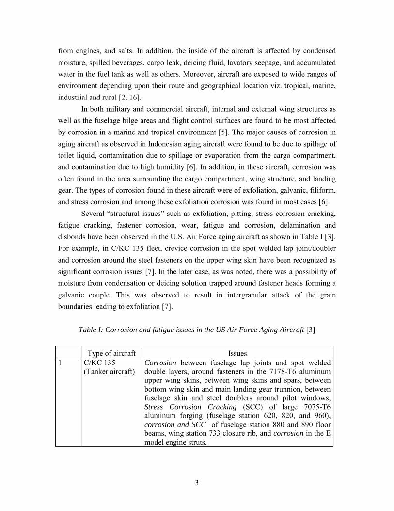
from engines, and salts. In addition, the inside of the aircraft is affected by condensedmoisture, spilled beverages, cargo leak, deicing fluid, lavatory seepage, and accumulatedwater in the fuel tank as well as others. Moreover, aircraft are exposed to wide ranges ofenvironment depending upon their route and geographical location viz. tropical, marine,industrial and rural [2, 16].
In both military and commercial aircraft, internal and external wing structures aswell as the fuselage bilge areas and flight control surfaces are found to be most affectedby corrosion in a marine and tropical environment [5]. The major causes of corrosion inaging aircraft as observed in Indonesian aging aircraft were found to be due to spillage oftoilet liquid, contamination due to spillage or evaporation from the cargo compartment,and contamination due to high humidity [6]. In addition, in these aircraft, corrosion wasoften found in the area surrounding the cargo compartment, wing structure, and landinggear. The types of corrosion found in these aircraft were of exfoliation, galvanic, filiform,and stress corrosion and among these exfoliation corrosion was found in most cases [6].
Several “structural issues” such as exfoliation, pitting, stress corrosion cracking,fatigue cracking, fastener corrosion, wear, fatigue and corrosion, delamination anddisbonds have been observed in the U.S. Air Force aging aircraft as shown in Table I [3].For example, in C/KC 135 fleet, crevice corrosion in the spot welded lap joint/doublerand corrosion around the steel fasteners on the upper wing skin have been recognized assignificant corrosion issues [7]. In the later case, as was noted, there was a possibility ofmoisture from condensation or deicing solution trapped around fastener heads forming agalvanic couple. This was observed to result in intergranular attack of the grainboundaries leading to exfoliation [7].
Table I: Corrosion and fatigue issues in the US Air Force Aging Aircraft [3]
Type of aircraft Issues1 C/KC 135
(Tanker aircraft)Corrosion between fuselage lap joints and spot weldeddouble layers, around fasteners in the 7178-T6 aluminumupper wing skins, between wing skins and spars, betweenbottom wing skin and main landing gear trunnion, betweenfuselage skin and steel doublers around pilot windows,Stress Corrosion Cracking (SCC) of large 7075-T6aluminum forging (fuselage station 620, 820, and 960),corrosion and SCC of fuselage station 880 and 890 floorbeams, wing station 733 closure rib, and corrosion in the Emodel engine struts.
4
Type of aircraft Issues2 C-141B
(Transportaircraft)
Widespread Fatigue Damage (WFD) in the fuel drain holesin the lower surfaces of the wings, corrosion and SCC inthe upper surface of the center wing, fatigue cracking andSCC around the wind shield, fatigue cracking in thestiffeners in the aft pressure door, SCC in the fuselage mainframes, and corrosion in the empennage.
3 C-5(Airlifter)
SCC of the 7075-T6 aluminum mainframes, keelbeam, andfittings in the fuselage, 7079-T6 fuselage lower lobe and aftupper crown.
4 B-52H(Bomber)
Cracking in the bulkhead at body station 694, fatiguecracking in flap tracks and in the thrust brace lug of theforward engine support bulkhead, cracking in the side skinof the pressure cabin, aft body skins, and upper surface ofthe wing.
5 F-15(Fighter aircraft)
Low-cycle fatigue cracking in the upper wing surfacerunouts, upper wing spar cap seal grooves, front wing sparconduit hole, upper in-board longeron splice plate holes,corrosion in nonhoneycomb structure including fuselagefuel tank, the outboard leading-edge structure of the wings,and the flap hinge beam.
6 F-16(Fighter aircraft)
Cracking of the vertical tail attachment bulkhead atfuselage station 479, fuel vent holes of the lower wing skin,the wing attach bulkhead at fuselage station 341, the upperwing skin, fastener problems on the horizontal tail supportboxbeam, and the ventral fin.
5
Type of aircraft Issues7 A-10
(Attack aircraft)Fatigue cracking in the wing auxiliary spar cutout of thecenter section rib at wing station 90, outer panel front sparweb at wing station 118 to 126, outer panel upper skin atleading edge. Fatigue cracking in the center fuselageforward fuel cell floor at the boost pump, forward fuselagegun bay compartment, forward fuselage lower longeron andskin at fuselage station 254, and center fuselage overwinglower floor panel stiffeners. Fatigue cracking in the aftnacelle hanger frame, thrust fitting and the engine inlet ringassembly skin/frame. Fatigue cracking in the main landinggear shock strut outer cylinder.Exfoliation corrosion in the 2024-T351 aluminum lowerwing skin, 7075-T6 aluminum upper wing at the leadingedge, 2024-T3511 aluminum lower front spar cap, 7075-T6aluminum fuselage bottom skin 2024-T3/7075-T6aluminum fuselage side skin and beaded pan, and 2024-T3511 aluminum horizontal stabilizer upper spar caps.Pitting corrosion in the 9Ni-4Co-0.3C steel wing attachfitting bushing and lug bore, main landing gear fittingattach bolts, 7075-T6 aluminum aft fuel cell aft bulkhead,and 2024-T351 center fuselage upper longeron.SCC in the wing attach bushing flange, and the mainlanding gear attach bolts.
8 E-3A(AirborneWarning andControl System)
Fatigue and corrosion in the 7178-T6 rudder skins, andspoiler actuator clevis. Exfoliation corrosion in the 7178-T6upper wing skin, leading edge slats, main landing gear door,fillet flap, fuselage stringer 23, and magnesium parts.Delamination and disbonds in the windows, floor panels,and nose radome core. Wear in the antenna pedestalturntable bearings.
9 E-8(JointSurveillance andAttack RadarSystem)
"Small" fatigue cracks in fastener holes in the 7075-T6aluminum stringers, in the 2024-T3 aluminum skins.
10 T-38(Air trainingcommand aircraft
Fatigue cracking in the lower surface of the wing, lowerwing skin fastener holes, wing skin access panel holes,milled pockets on the lower wing skin, and the fuselageupper cockpit longerons.SCC in the fuselage cockpit upper and lower longerons,fuselage forgings.honeycomb corrosion in the horizontal stabilizer (due towater intrusion), and the landing gear strut door

6
Examination of C/KC 135 fuselage lap splices (stiffened aluminum lap joint)revealed that outer skin corrosion was predominantly intergranular and exfoliation [8].Moreover, extensive cracking was noted at these sites in the outer skin. In addition,extensive "pillowing" with more than 300% change in volume due to corrosion productsalong the faying surfaces was observed. In the rivet/shank region, severe localizedcorrosion and intergranular corrosion were observed. The fracture of rivet heads wasattributed to high local stress due to environmentally assisted cracking at the junction. Aswell, in this study, solution samples were collected from selected areas of lap splice jointsand the solution analysis showed the presence of several cations such as Al3+, Ca2+,Na+, K+, and Ni2+ and also anions Cl-, SO42-, and NO3-. Subsequent potentiodynamic
tests using solution containing these ions led to the belief that dissolution rates couldcompletely penetrate the fuselage outer skin during service life [8].
Thus, in addition to fatigue cracking, different corrosion mechanisms occur inaircraft structures depending upon their location, geometry, exposure to environment, andloading conditions. Research studies conducted within the Quality and Integrity DesignEngineering Center (QIDEC) at the University of Utah as well as other related studies arebriefly discussed below.
1.2 Intergranular and Exfoliation Corrosion
Exfoliation corrosion is believed to be a manifestation of intergranular corrosion.Intergranular corrosion results from either the segregation of reactive impurities or fromthe depletion of passivating elements at the grain boundaries. This makes the regions ator surrounding the grain boundaries less resistant to corrosion resulting in preferentialcorrosion. The high strength aluminum alloys such as 2xxx and 7xxx series are highlysusceptible to intergranular corrosion [1]. Exfoliation corrosion is a form of intergranularattack that occurs at the boundaries of grains elongated in the rolling direction. The 7xxxseries aluminum alloys are particularly less resistant to exfoliation corrosion becauseduring heat treatment (to achieve maximum desirable strength) their constituent elementscopper and zinc accumulate at grain boundaries leaving the adjacent region free ofprecipitates. As aluminum and aluminum intermetallic compounds are highly reactive inthe emf series as well as aluminum is anodic to copper in the galvanic series, the resultinggalvanic couples cause the grain boundaries to preferentially corrode (intergranularattack). McIntyre and Dow have related the localized corrosion problems in the 7075-T7352 fuel tanks of underwater weapon systems to intergranular corrosion [9]. In theirstudy, aluminum alloys 7075 and 6061 were exposed to artificial seawater containing
7
nitrate ions. It was observed that accelerated intergranular corrosion occurred in 7075alloy. From the test results, they hypothesized that refueling the improperly cleaned fueltank may cause the propellant in contact with the small quantity of sea water remaining inthe fuel tank resulting in the release of nitrate ions from an hydrolysis process leading toreduced pH that may cause the dissolution of the oxide film (localized corrosion). Theyfurther hypothesize that corrosion eventually propagates to the bulk regions of the alloydue to intergranular attack by the preferential corrosion of reactive MgZn2 intermetallic
compounds located at grain boundaries. This was found to be true for 7075 aluminumalloy but not for 6061 aluminum alloy because the later does not contain either Cu or Znas alloying element [9].
Reducing the impurities such as iron and silicon as well as heat treatmentmodifications in aluminum alloys have resulted in increase in the resistant to exfoliationcorrosion [10]. For example, overaged 7075-T7 alloy is more resistance to exfoliationcorrosion when compared to 7075-T6 alloy. In addition, Rinnovatore showed that in theT6 temper, exfoliation corrosion resistance was found to be greater for forgings producedfrom rolled bar stock than forgings from extruded bar stock [11]. Moreover, it was shownthat rapid quenching from the solution temperature in cold water increased exfoliationcorrosion resistance of forgings tempered to T6.
Fatigue and exfoliation interactions have been studied. Mills reports that most ofthe studies have been performed during the last five years on this issue although Shafferin 1968 reported significant reduction in the fatigue life of exfoliated extruded 7075-T6spar caps [12]. Moreover, multiple crack nucleation sites were observed in 7075-T651[13], and 2024-T3 [14] aluminum alloy specimens when the specimens were subjected toexfoliation corrosion and then fatigue tested. Mills found an 88% decrease in the fatiguelife of the specimens with prior exfoliation corrosion damage when compared tospecimens tested without prior corrosion damage. Chubb et al. showed in their studyusing panels containing fastener holes that the end grains exposed in the rivet holeswould be the potential corrosion sites that could eventually result in multiple site damage.
In a recent study [12], experiments were performed to determine the effect ofexfoliation on the fatigue crack growth behavior of 7075-T651 aluminum alloy. First thespecimens were subjected to prior-corrosion damage using ASTM standard EXCOcorrosive solution and then fatigue tested in corrosion fatigue environments of dry air,humid air, and artificial acid-rain. Test results indicated that prior-corrosion damageresulted in higher crack growth rates when tested in dry air as well as in acid-rainenvironments when compared to uncorroded specimens. Fractographic analysis showedquasi-cleavage fracture close to the exfoliated edge of the specimens tested in all the
8
three environments indicating embrittlement by prior-corrosion. Thus, embrittlement byprior-corrosion was stated to “result in accelerated crack nucleation, faster short crackgrowth, and earlier onset of fatigue phenomena such as multiple-site damage”.
1.3 Corrosion fatigue
Corrosion fatigue is defined as "the process in which a metal fracturesprematurely under conditions of simultaneous corrosion and repeated cyclic loading atlower stress levels or fewer cycles than would be required in the absence of the corrosiveenvironment" [4]. Corrosion acting conjointly with fatigue can have major effects onmaterials in structures of aircraft. First, corrosion can create discontinuities (pits, cracks,etc) that act as origins of fatigue cracks with significant reductions in life at all stresslevels. In crack propagation, corrosion effects are well known to produce acceleratedfatigue crack propagation. The combination of aggressive environment and cyclic loadingconditions have been observed to accelerate crack growth rates in aluminum alloys.Several mechanisms were proposed to explain the corrosion fatigue process [1]. Theyare: (i) dissolution of material at the crack tip in corrosive environment, (ii) hydrogenembrittlement in which diffusion of hydrogen (a by product of corrosion process) into thelattice space that could weaken the atomic bonds thereby reducing the fracture energy,(iii) theory of adsorbed ions in which the transport of critical species to the crack tipresults in lowering of the energy required for fracture, and (iv) film-induced cleavage inwhich it is hypothesized that crack speed would increase at the film-substrate interfacewhen the crack grows through the low toughness oxide layer leading to the rupture of thefilm.
In general, corrosion fatigue effects on crack propagation are more pronounced atlower stress intensities whereas at higher stress intensities the crack propagates at such ahigh rate that the effects of chemical dissolution or localized embrittlement will benegligible. Several parameters affect corrosion fatigue crack propagation rates. Forexample, crack growth rates increase with increase in the stress intensity range. Also, atlower frequency corrosion fatigue effects will be more severe than at higher frequencybecause of the time dependent nature of the process. Increase in R value has been foundto generally increase corrosion fatigue crack propagation rates. As well, increasing theconcentration of corrosive species, lowering the pH, increasing the moisture content, andtemperature usually result in more severe effects [4].
The most common corrosion fatigue environment that is simulated in laboratorytesting is 3.5% NaCl as it is believed to result in severe general corrosion rates as well as
9
it represents roughly the salinity of sea water. In addition, other environments such ashumid air, salt sprays, and artificial acid rain (to simulate industrial pollutants) also areused to characterize corrosion fatigue crack growth behavior of aluminum alloys. Asaircraft are exposed to several complex chemical environments both inside and outside,no single environment could simulate the actual condition. Therefore, a few studies usedsump tank water that was considered close to a "realistic chemical environment" [15].The quest for realistic corrosion fatigue environment led Swartz et al. [16] to collect andanalyze solution samples from bilge areas, external galley and lavatories of five differentairplanes. As a result, a new chemical environment was developed to perform corrosionfatigue crack growth experiments on 2024-T351, 2324-T39, 7075-T651, and 7150-T651aluminum alloys. For all the alloys studied the fatigue crack propagation rates in syntheticbilge solution were found to be between the dry air and the 3.5% NaCl data. In anotherstudy [17], cyclic wet and dry environment was simulated in characterizing the corrosionfatigue crack growth rates in 2024-T351 aluminum alloy. It was hypothesized that duringthe dry cycle the partial evaporation of the aqueous solution may allow some chemicalspecies to get deposited at the crack tip and then in the wet cycle when the rehydrationoccurs, corrosion could occur at a greater rate than before.
To simulate aircraft service corrosion, fatigue crack growth studies wereconducted on service corroded 2024-T3 aluminum panels extracted from a C/KC-135aircraft [18]. Test results showed that in some cases fatigue crack growth rates were twoor three times greater in the corroded material, however, in other cases, there was littledifference. It was observed that "the difference in the crack growth rates was due to highvariability in the amount of corrosion damage between specimens".
1.4 Corrosion pillowing and its effect on structural integrity of aircraft lap joints
Recently, some studies have shown that the increase in stress levels is not onlybecause of the thickness loss due to corrosion but also due to the volume of the corrosionproduct build-up in a joint [19]. Also, evidences show that lap joints contain "fayingcracks" under the rivet heads in the corroded areas. The complexity of this issue asexplained by Komorowski et al. is that "the majority of the cracks had not penetrated theouter skin surface and appeared to grow more rapidly along the faying surface creating ahigh aspect ratio semi-elliptical crack and it is difficult to detect and affects the structuralintegrity of the joint" [19]. As reported by Krishnakumar et al.[20], the major corrosionproduct in the lap splices is found to be aluminum oxide trihydrate, an "oxide mix" whichhas a high molecular volume ratio to the alloy. As the oxide is insoluble, it is found to

10
remain within the joint and in turn is responsible to deform the skins in the joint whichusually gives a bulging appearance, commonly termed as "pillowing". Moreover, finiteelement analysis revealed that for a two layer joint the stresses due to 6% thinning due tocorrosion resulted in stress more than the yield strength of 2024-T3 aluminum alloy [21].In addition, "pillowing induced deformation" was observed on the corroded joints afterremoval of the rivets and the separation of the skin. Moreover, multiple cracks werefound to nucleate from rivet holes. Fracture mechanics analysis has shown that as thepillowing increases, the stress intensity factor for the crack edge along the faying surfaceincreases [22]. On the other hand, the stress intensity factor decreases for the crack edgealong the outer surface. Therefore, it was hypothesized that pillowing producescompressive stresses in the rivet area on the outer surface because of the resultantbending stresses. At the same time, high tensile stress is produced on the faying surfaceresulting in more rapid growth of faying surface cracks in the direction of the row ofrivets than through the skin towards the outer surface [22].
1.5 Pitting corrosion
Pitting corrosion is defined as “localized corrosion of a metal surface, confined toa point or small area, that takes the form of cavities” [4]. Pitting is a deleterious form oflocalized corrosion and it occurs mainly on metal surfaces which owe their corrosionresistance to passivity. The major consequence of pitting is the breakdown of passivity,i.e. pitting, in general, occurs when there is breakdown of surface films when exposed topitting environment. Pitting corrosion is so complicated in nature because “oxide filmsformed on different metals vary one from another in electronic conduction, porosity,thickness, and state of hydration” [23]. The empirical models that have been developed tounderstand the pitting process are closely related to the integrity of the metal oxide film.The salient features of the empirical theories related to pit nucleation mechanisms arementioned in Table II.

11
Table II Pit Nucleation Theories
Proposed by TheoryEvans et al. [24](1929-30)
Proposed penetration theory. Ability of a chloride ion to penetrate thefilm was linked to the occurrence of pitting. Halide ions are assumedto be transported from the film-solution interface to the metal-oxideinterface either by the application of electric field or exchange ofanions.
Hoar et al.[25,26](1960s)
Assumed the adsorption of anions on the oxide surface as the keyaspect in the pit nucleation process.Proposed “ion-migration” model that involves activating anions thatenter the oxide film lattice without exchange thereby increasing theionic conductivity of the film resulting in local high anodicdissolution rates and pitting.Proposed “mechanical” model in which it was assumed thatadsorption of anions at the oxide-solution interface lowers theinterfacial energy resulting in the formation of cracks in theprotective oxide film under the influence of the “electrostaticrepulsion” of the adsorbed anions.Suggested a concept of local acidification of pit as a critical factor inpit growth.
Uhlig [27]andKolotyrkin [28](1961-1967)
Proposed adsorption theory in which at a certain value of thepotential (pitting potential) the adsorption of aggressive anions on themetal surface displaces the passivating species such as oxygen.Kolotyrkin suggested that adsorption of anions at preferred sitesforming soluble complexes with metal ions from the oxide. Oncesuch species leave the oxide, thinning of the film starts locallyincreasing the electric field strength which accelerates the dissolutionof the oxide.
Sato [29,30](1971, 1982)
Proposed that at a critical potential an internal film pressure exceedsthe critical compressive stress for film fracture.Considered thinning of film at local sites and suggested that pittingoccurs only when a critical concentration of aggressive anions and acritical acidity is locally built up.
Macdonald et al.[31](1981)
Proposed that metal vacancies may accumulate as a result of thediffusion of metal cations from the metal/film to the film/solutioninterface, forming voids at the metal/film interface. When the voidsgrow to a critical size the passive film will collapse leading to pitgrowth.
Therefore, nucleation of pits generally involves certain localized changes in thestructure and properties of the oxide film. However, propagation of pits is related to the
12
dissolution of the underlying bulk metal. Further discussion on this subject is presentedlater in this report.
1.6 Pitting corrosion fatigue
In corrosion fatigue conditions, as mentioned before, several studies showedgreater increase in fatigue crack growth rates compared to “baseline” fatigue conditions.Although major efforts were expended to understand the crack propagation behavior ofmaterials, a few studies have focused on the crack nucleation stage in the overall fatigueprocess [32,33,39]. McAdam first suggested that corrosion induced pits might act asstress concentrators from which cracks could form [34]. A large number of chemical orelectrochemical factors such as potential, passive film, pH, and composition ofenvironment are found to affect the pitting corrosion fatigue process. As well, mechanicalfactors such as stress range, frequency, stress ratio (R), and load waveform andmetallurgical factors such as material composition, microstructure, heat treatment, andorientation can influence pitting corrosion fatigue process. Nucleation of cracks fromcorrosion pits were observed by many researchers including the works of Hoeppner[32,33,39], Goto [35] in heat-treated carbon steel, and Muller [36] in several steels. Aswell, in NaCl environment, lowering of the fatigue life due to the generation of pits incarbon steel [37] and 7075-T6 aluminum alloy [38] was observed under corrosion fatigueconditions.
The Linear Elastic Fracture Mechanics (LEFM) concepts are widely used tocharacterize the crack growth behavior of materials under cyclic stresses in differentenvironmental conditions. It is important to note that both pitting theory and crack growththeory have been used in model development as follows. Pit growth rate theory proposedby Godard is combined with the fatigue crack growth concepts. The time (or cycles orboth) to nucleate a Mode I crack from the pit (under cyclic loading) could be modeledusing LEFM concepts. Based on this idea, a few models [39-42] were proposed. All ofthe models assume hemispherical geometry for the pit shape and the corresponding stressintensity relation is used to determine the critical pit depth using the crack growththreshold (∆Kth) that is found empirically. For a hemispherical pit geometry, these modelsprovide a reasonable estimate for the total corrosion fatigue life. Details of these modelsare presented later in this report.

13
1.7 Fretting corrosion and fatigue
Virtually all mechanical joints of fixed wing aircraft, rotary wing aircraft, engine,gearbox and other electrical and mechanical components of aircraft are susceptible to theoccurrence of fretting fatigue. The complexities of fatigue design, either safe-life ordamage tolerant, are enough to challenge the most talented technical personnel. Add tothat the occurrence of fretting and truly complex phenomena occur.
Fretting fatigue was originally discovered in the early part of the 20th century.Since that time a great deal of work has been done to understand the mysteries of frettingfatigue. As well, engineers have devoted a significant effort to studying fretting fatigue tobe able to cope with the potentially deleterious effects it may have on the life ofengineering components.
Fretting is a phenomenon that involves both environmental effects (corrosion inmetals) and wear. Thus, it is a complex phenomenon. When it acts with cyclic loading onengineering components the result frequently is to shorten the fatigue life or to lower thefatigue design allowable
Historically three approaches have been employed in fretting fatigue studies. Oneapproach is to perform fretting fatigue testing by simulating the contact or fasteningconditions. The fretting fatigue test results thus generated are used to determine thefretting fatigue life reduction factor Kff. Although this approach has been to introduce afretting fatigue life reduction factor into the fatigue design process this is not always asatisfactory procedure. A second approach is to develop the fatigue structural allowablesby testing the mechanical joints and including fretting considerations in these tests.Another approach is to use a fretting protection and control plan to focus on potentiallyblocking the occurrence of fretting or to prevent the propagation of cracks from frettingdamage areas. This approach simulates fretting damage that will assist in developinggreater understanding of the basic mechanisms of fretting which in turn will lead to thedevelopment of standardized fretting fatigue test methods. In addition, this approach willhelp to find some preventive systems to alleviate fretting fatigue problems on structuralcomponents. This mechanistic approach also will be useful to develop inspection system.Some investigators are coupling damage tolerance concepts to fretting studies to assist inmore accurate tracking of damage as well as setting more realistic inspection intervals.Therefore, one of the needs for improved fretting fatigue resistance is the development ofadequate experimental procedures to simulate fretting fatigue phenomena.
14
1.7.1 Mechanisms of fretting
Fretting is believed to rupture the protective oxide film of the metal alloys that arein contact although the influence of oxide film is brief in the subsequent degradationmechanism of fretting. Therefore, it is commonly believed that the first stage of fretting isadhesive contact of the asperities on contact surfaces [43]. Microscopic plasticdeformation of the contacting asperities in relative motion may result in the nucleation ofcracks. In addition, metal transfer may occur from one surface to another depending onthe hardness and the relative displacement of the contacting surfaces. The production offretting debris and the oxidation of the fresh surface may result in the buildup of oxideson the contacting surfaces. These may result in the formation of pits on the contactingsurfaces. These damages may very well accelerate the nucleation of cracks. Depending onthe contact stress state the nucleated cracks may result in the early propagation in a rapidmanner. Contact stresses are high enough to significantly influence crack propagation.The cracks may propagate at various rates and angles. Subsequent final propagation ofcracks may depend on the bulk stress alone rather than on the contact stress. As the crackgrows into the material, a depth is reached beyond which the contact stresses have littleor no influence and the applied cyclic stresses play a dominant role. Therefore, thefretting process can be divided into four stages viz. nucleation of cracks, earlypropagation of cracks by contact stress state, final propagation of cracks by bulk stressand instability resulting in the decreased fatigue life. The aforementioned fretting processis dependent on many different variables such as material microstructure, stress state,environment, relative slip amplitude, and contact pressure.
The theories related to nucleation of fretting fatigue cracks are usually based onthe adhesive contact of the asperities as well as the cracks that form subsurface.Displacements that are "small" on a macroscopic scale are very large when acting onasperities. Relative movement of adhesively bonded asperities results in plastic or near-plastic strains around asperities. The importance of the formation of oxides may be basedon their affect on adhesive contacts. Oxides prevent direct metal contact and reducecoefficient of friction by rolling. However, under certain conditions, such as the presenceof discontinuities and/or sliding motion, cracks could nucleate subsurface.
Dependent upon nucleation and contact stress state it has been observed that aftera specific time, fretting contact no longer affects the fatigue life. This implies thatnucleation occurs very early. In addition, it should be noted that fatigue life reductionoccurs only after a specific amount of fretting damage and also the nucleated crack mustbe large enough to propagate under bulk stress alone [44].

15
1.7.2 Fretting fatigue in aircraft joints
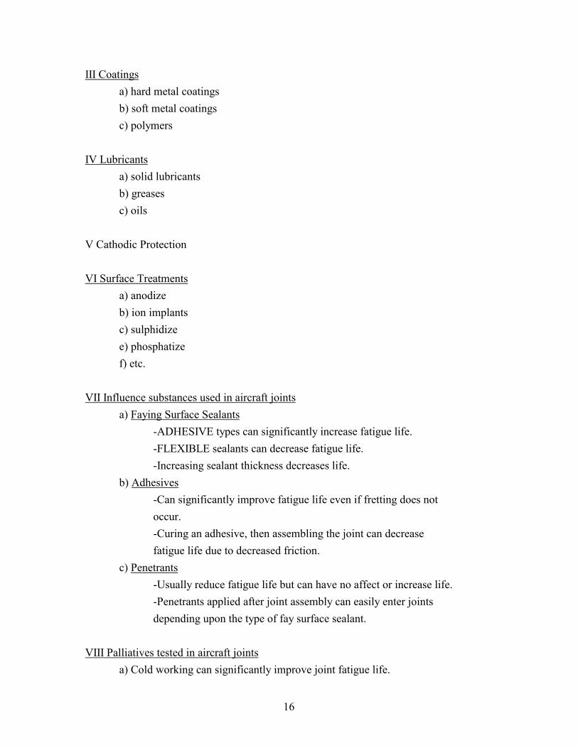
Fretting fatigue has been observed as a potential degradation mechanism inaircraft structural components [45]. Many cracks have been found to originate at fastenersand on faying surfaces. Cracks may form due to fretting mechanisms from one or morerivet holes leading to the concept of multiple-site damage. Evidence supports thatelimination of fretting with adhesives greatly increases fatigue life [46]. Also, it has beenobserved that cracks appear in lugs much sooner if fretting is present. In addition, failuresobserved originating at areas of fretting damage, often away from fastener holes. Fig. 3shows a schematic of the design methods proposed in the past by Hoeppner to minimizethe effect of fretting fatigue in aircraft joints. In addition, the methods to alleviate frettingfatigue challenge in aerospace components are provided in the next section.
1.7.3 Reduction or prevention methods
The following are some methods that can be employed to reduce the problem offretting fatigue in aircraft joints [47].
I Designa) prevent all relative motion of the surfacesb) prevent the surfaces from contactingc) surface roughnessd) surface hardnesse) etc.
II Mechanical Methodsa) shot peeningb) vapour blastingc) bead blastingd) surface rollinge) dimpling
These methods include processes that cold-work the surface and introduce residualsurface compressive stresses.
16
III Coatingsa) hard metal coatingsb) soft metal coatingsc) polymers
IV Lubricantsa) solid lubricantsb) greasesc) oils
V Cathodic Protection
VI Surface Treatmentsa) anodizeb) ion implantsc) sulphidizee) phosphatizef) etc.
VII Influence substances used in aircraft jointsa) Faying Surface Sealants
-ADHESIVE types can significantly increase fatigue life. -FLEXIBLE sealants can decrease fatigue life. -Increasing sealant thickness decreases life.
b) Adhesives -Can significantly improve fatigue life even if fretting does not
occur. -Curing an adhesive, then assembling the joint can decrease fatigue life due to decreased friction.
c) Penetrants -Usually reduce fatigue life but can have no affect or increase life. -Penetrants applied after joint assembly can easily enter joints depending upon the type of fay surface sealant.
VIII Palliatives tested in aircraft jointsa) Cold working can significantly improve joint fatigue life.

17
b) Solid lubricants escape from the joint or are wiped away.c) Teflon usually decreases fatigue life due to load transfer to fastener shanks.
In summary, adhesion based mechanisms of fretting fatigue appear to be mostcommon and fretting contact significantly increases stress at and near the surface.It should be noted that palliative effectiveness is extremely CASE SPECIFIC and onlymethods which induce surface residual compressive stresses consistently increase frettingfatigue life. Moreover, evidences show that fretting fatigue is a pervasive mode of failurewith riveted aircraft joints. Furthermore, methods which reduce fretting in aircraft jointsoften do not increase the fatigue life as a reduction in coefficient of friction requires moreload to be taken by the fastener shank.

18
Figure 3. Design method for fretting fatigue in aircraft joints (Hoeppner-1993)

19
1.8 References
1. Jones, D., Principles and prevention of corrosion, Macmillan Publishing Co., N.Y.,1992, pg. 4.
2. Wallace and Hoeppner, "Aircraft corrosion: causes and case histories", AGARD
Corrosion Handbook, Vol. 1, AGARD-AG-278-Vol. 1, 1985. 3. Aging of U.S. Air Force Aircraft, National Research Council (NRC) National
Materials Advisory Board (NMAB) report, National Academy Press,Washington,D.C., 1997.
4. Metals Handbook - Ninth Edition, Corrosion, Vol. 13, 1987, Publ: American Society
for Metals (ASM), Metals Park, OH. 5. Alvarez, A., “Corrosion on aircraft in marine-tropical environments: a technical
analysis”, Material Performance, May 1997, pp. 33-38. 6. Suyitno, B.M. and Sutarmadji., “Corrosion control assessment for Indonesian aging
aircraft”, Anti-corrosion Methods and Materials, Vol. 44, No. 2, November 1997, pp.115-122.
7. Groner, D.J., “US Air Force aging aircraft corrosion”, Current Awareness Bulletin,
Structures Division, Wright Laboratory, Spring 1997. 8. Piascik, R.S., Kelly, R.G., Inman, M.E., and Willard, S.A., “Fuselage lap splice
corrosion”, WL-TR-96-4094, Vol. II, ASIP, 1996. 9. McIntyre, J.F. and Dow, T.S., “Intergranular corrosion behavior of aluminum alloys
exposed to artificial seawater in the presence of nitrate anion”, Corrosion, Vol. 48,No. 4, pp. 309-319, 1992.
10. Thompson, J.J., Tankins, E.S., and Agarwala, V.S., “A heat treatment for reducing
corrosion and stress corrosion cracking susceptibilities in 7xxx aluminum alloys”,Materials Performance, June 1987, pp. 45-52.
11. Rinnovatore, J.V., Lukens, K.F., and Corrie, J.D., “Exfoliation corrosion of 7075
aluminum die forgings”, Corrosion, Vol. 29, No. 9, 1973, pp. 364-372. 12. Mills, T.B., “The combined effects of prior-corrosion and aggressive chemical
environments on fatigue crack growth behavior in aluminum alloy 7075-T651”,Ph.D. Dissertation, University of Utah, 1997.
13. Mills, T.B., “The effects of exfoliation corrosion on the fatigue response of 7075-
T651 aluminum plate,” M.S. Thesis, University of Utah, 1994.
20
14. Chubb, J.P., Morad, T.A., Hockenhull, B.S., and Bristow, J.W., “The effect ofexfoliation corrosion on the fatigue behavior of structural aluminum alloys”, inStructural Integrity of Aging Airplanes, 1991, pp. 87-97.
15. Pettit, D.E., Ryder, J.T., Krupp, W.E., and Hoeppner, D.W., “Investigation of the
effects of stress and chemical environments on the prediction of fracture in aircraftstructural materials, AFML-TR-74-183, 1974.
16. Swartz, D.D., Miller, M. and Hoeppner, D.W., "Chemical Environments in
Commercial Transport Aircraft and Their Effect on Corrosion Fatigue CrackPropagation", in Estimation, Enhancement and Control of Aircraft FatiguePerformance, Vol. I, J.M. Grandage and G.S. Jost, Eds., The proceedings of the 14thsymposium of the International Committee on Aeronautical Fatigue, 3-5 May, 1995,Melbourne, Australia, pp. 353-364.
17. Kramer, J., and Hoeppner, D.W., “Effects of Cyclic Immersion in 3.5% NaCl
Solution on Fatigue Crack Propagation Rates in Aluminum 2024-T351”, Proceedingsof the 1995 USAF Structural Integrity Program Conference, WL-TR-96-4093, Vol.II, pp. 1089-1112.
18. Mills, T.B., Magda, D.J., Kinyon, S.E., and Hoeppner, D.W., “Fatigue crack growth
and residual strength analyses of service corroded 2024-T3 aluminum fuselagepanels, Report to Oklahoma City Air Logistics Center and Boeing Defense andSpace Group, University of Utah, 1995.
19. Komorowski, J.P., Bellinger, N.C., and Gould, R.W., “The role of corrosion
pillowing in NDI and in the structural integrity of fuselage joints”, in Fatigue in Newand Aging Aircraft, Proceedings of the 19th Symposium of ICAF 1997.
20. op-cit ref. 19. 21. Bellinger, N.C., Komorowski, J.P., and Gould, R.W., “Damage Tolerance
Implications of Corrosion Pillowing on Fuselage lap joints”, AIAA journal. 22. Bellinger, N.C., and Komorowski, J.P., “Corrosion pillowing stresses in fuselage lap
joints,” AIAA journal, Vol. 35, No. 3, 1997. 23. Jayalakshmi, M., and Muralidharan, “Empirical and deterministic models of pitting
corrosion - an overview”, Corrosion Reviews, Vol. 14, Nos. 3-4, 1996, pp. 375-402. 24. Evans, V.R., J. Chem. Soc., 92, 1929. 25. Hoar, T.P., “The Production and Breakdown of the Passivity of Metals”, Corrosion
Science, Vol. 7, 1967, pp. 341-355. 26. Hoar and Wood, “The sealing of porous anodic oxide films on aluminum,”
Electrochemica Acta, 7, 1962, pg. 333

21
27. Bohni and Uhlig, H.H., “Environmental Factors Affecting the Critical Pitting
Potential of Aluminum,” Journal of the Electrochemical Society, Vol. 116, 1969, pp.906-910.
28. Kolotyrkin, Ya, M., “Effects of Anions on the Dissolution Kinetics of Metals,”
Journal of the Electrochemical Society, Vol. 108, No. 3, 1961, pp. 209-216. 29. Sato, N., Electrochemica Acta, 16, 1971, pg. 1683. 30. Sato, N., “Anodic Breakdown of Passive Films on Metals”, and “The Stability of
Pitting Dissolution of Metals in Aqueous Solution,” Journal of the ElectrochemicalSociety, Vol. 129, No. 2, 1982, pp. 255-260 and 260-264.
31. Lin, Chao, and Macdonald, “A point defect model for anodic passive films II.
Chemical breakdown and pit initiation,” Journal of the Electrochemical Society,Vol. 128, No. 6, 1981, pp. 1194-1198.
32. Hoeppner, D.W., Mann, and Weekes, “Fracture mechanics based modelling of
corrosion fatigue process,” in Corrosion Fatigue: Proceedings of the 52nd meeting ofthe AGARD Structural and Materials Panel held in Turkey, 5-10 April, 1981.
33. Hoeppner, D.W., Corrosion fatigue considerations in materials selections and
engineering design”, Corrosion Fatigue: Chemistry, Mechanics, and Microstructure,NACE, 1972, pp. 3-11.
34. McAdam, D.J., and Gell, G.W., “Pitting and its effect on the fatigue limit of steels
corroded under various conditions”, Journal of the Proceedings of the AmericanSociety for Testing Materials, Vol. 41, 1928, pp. 696-732.
35. Goto, M., and Nisitani, H., “Crack initiation and propagation behavior of a heat
treated carbon steel in corrosion fatigue”, Fatigue Fracture Engineering MaterialStructure, Vol. 15, No. 4, 1992, pp. 353-363.
36. Muller, M., “Theoretical considerations on corrosion fatigue crack initiation”,
Metallurgical Transactions, Vol. 13A, 1982, pp. 649-655. 37. Mehdizadeh, P., et al., “Corrosion fatigue performance of a carbon steel in brine
containing air, H2S, CO2”, Corrosion, Vol. 22, 1966, pp. 325-335. 38. Corsetti, L.V., and Duquette, D.J., “The effect of mean stress and environment on
corrosion fatigue behavior of 7075-T6 aluminum”, Metallurgical Transactions, Vol.5, 1974, pp. 1087-1093.
39. Hoeppner, D.W., “Model for Prediction of Fatigue Lives Based Upon a Pitting
Corrosion Fatigue Process,” Fatigue Mechanisms, Proceedings of an ASTM-NBS-

22
NSF Symposium, J.T. Fong, Ed., ASTM STP 675, American Society for Testing andMaterials, 1979 pp. 841-870.
40. Lindley, T. C., McIntyre, P., and Trant, P. J., “Fatigue Crack Initiation at Corrosion
Pits,” Metals Technology, Vol. 9, 1982, pp. 135-142. 41. Kawai, S. and Kasai, K., “Considerations of Allowable Stress of Corrosion Fatigue
(Focused on the Influence of Pitting),” Fatigue Fracture of Engineering MaterialsStructure, Vol. 8, No. 2, 1985, pp. 115-127.
42. Kondo, Y., “Prediction of Fatigue Crack Initiation Life Based on Pit Growth,”
Corrosion Science, Vol. 45, No. 1, 1989, pp. 7-11. 43. Hoeppner, Mechanisms of fretting fatigue, Keynote Paper, in Fretting Fatigue, ESIS
18, Mechanical Engineering Publications, London, (1994) 3-19. 44. Hoeppner and G.L. Goss, A fretting fatigue damage threshold concept, Wear, 27,
(1974) 61-70. 45. Hoeppner and S. Adibnazari, Fretting fatigue in aircraft joints, in Durability and
Structural Integrity of Airframes, International Committee of Aeronautical Fatigue(ICAF), (1993) 191-207.
46. Hoeppner, "Fretting of aircraft control surfaces," in AGARD Conference Proceedings
No. 161, Specialists Meeting on Fretting in Aircraft Systems, (1974), 1.1-1.7. 47. Hoeppner, S. Adibnazari and M. W. Moesser, “Literature review and preliminary
studies of fretting and fretting fatigue including special applications to aircraft joints,”DOT/FAA/CT-93/2, (1994).
23
2 Pitting Corrosion
2.1 Introduction
Pitting is classified as a localized attack that results in rapid penetration andremoval of metal at “small” discrete areas [1]*. An electrolyte should be present forpitting to occur. The electrolyte could be a film of condensed moisture, or a bulk liquid.How and when pitting occurs on a metal depends on numerous factors, such as, type ofalloy, its composition, integrity of its oxide film, presence of any material ormanufacturing induced discontinuities as well as chemical and loading environment, toname a few. Many metals and their alloys are subject to pitting in different environments.These include alloys of carbon steels, stainless steels, titanium, nickel, copper, andaluminum [2].
In passivated metals or alloys that are exposed to solutions containing aggressiveanions, primarily chloride, pitting corrosion results in local dissolution leading to theformation of cavities or “holes”. The shape of the pits or cavities can vary from shallowto cylindrical holes and the cavity is approximately hemispherical [3]. The pitmorphology depends on the metallurgy of the alloy and chemistry of the environment aswell as the loading conditions. As observed first by McAdam in 1928, these pits maycause local increase in stress concentration and cracks may nucleate from them [4].
According to Foley [5], pitting corrosion of aluminum occurs in four steps: (1)adsorption of anions on the aluminum oxide film, (2) chemical reaction of the adsorbedanion with the aluminum ion in the aluminum oxide lattice, (3) penetration of the oxidefilm by the aggressive anion resulting in the thinning of the oxide film by dissolution, and(4) direct attack of the exposed metal by the anion.
The susceptibility of a metal to pitting corrosion as well as the rate at whichpitting occurs on its surface depends on the integrity of its oxide film. Therefore, a briefoverview of the mechanisms of the formation of passive film is discussed below.
2.2 Formation of passive films and their growth
The following discussion on the oxide film formation and its growth is extractedfrom ref. (6).
* Numbers in parentheses [ ] refer to references at the end of each section.

24
Early investigators examined the effects of natural waters on metals by placingthem outside. One investigator, Liversidge, in 1895, observed that an aluminumspecimen,
….lost its brilliancy, and became somewhat rough and speckled with grey spotsmixed with larger light grey patches; it also became rough to the feel, the greyparts could be seen to distinctly project above the surface, and under themicroscope they presented a blistered appearance. This encrustation is heldtenaciously, and does not wash off, neither is it removed on rubbing with a cloth[7].
Liversidge proposed that a hydrated aluminum oxide had formed, but did notconfirm this with further testing of the layer. He did, however, note that when weighed,the aluminum specimens gained weight with exposure, rather than losing weight [8]. Itwas later confirmed that the weight gain was due to formation of an oxide film [9].Although Liversidge suggested the formation of an aluminum oxide film, subsequentinvestigators proposed other theories to explain the passive behavior of aluminum. Someof these were changes in the state of electric charge on the surface, changes in valence atthe surface, and a condensed oxygen layer [10]. The presence of the oxide film on thesurface of the metals was proven by Dunstan and Hill in 1911. Through experiments withiron, they determined that the passive film was reduced at 250 °F, the temperature atwhich magnetic iron oxide is reduced. Similar films were found on other metals [10].Barnes and Shearer attempted to determine the constitution of passive films on aluminumand magnesium in 1908. They determined that aluminum formed hydrogen peroxidewhen reacting with water and that the passive film consisted of Al2(OH)6 [9]. This waslater determined to be incorrect [11].
2.3 Structure of the passive film in aluminum
It later was determined that this film on aluminum consists of an aluminum oxidecreated when the aluminum comes in contact with an environment. Generally, this film isamorphous; however, under certain circumstances it will develop one of seven crystallinestructures:1. Gibbsite (also called hydrargillite): (α-Al2O3•3H2O)2. Bayerite: (β-Al2O3•3H2O)3. Boehmite: (α-Al2O3•H2O or AlO•OH)4. Diaspore: (β-Al2O3•H2O)

25
5. Gamma alumina: (γ-Al2O3)6. Corundum: (α-Al2O3)7. Combinations of aluminum oxides with inhibitors, for example (2Al2O3•P2O5•3H2O)
Gibbsite and diaspore structures are not found during corrosion of aluminum, butare frequently found in bauxite ores. Boehmite, bayerite, gamma alumina, and corundumare sometimes found in the passive layers of aluminum under certain conditions.Additionally, bayerite is frequently found as a corrosion product during pitting ofaluminum. Combinations of aluminum oxides with inhibitors are not understood verywell in the literature, but it is known that they will combine with oxide layer to formimproved corrosion resistance through changing the passive film structure. Changes inthe amorphous structure of the oxide film have been studied by several researchers. Inone investigation, the passive film formed on the pure aluminum sheet revealed changesin structure with an increase in temperature and oxygen content. Prior to heating, thestructure was reported to be amorphous oxide. As the temperature was increased, theamorphous film thickened, formed boehmite, and bayerite. The rate of film formationincreased with temperature, and with an increase in oxygen content, intergranular attackbegan. The researcher suggested the following sequence of events in the formation:boehmite is nucleated at dislocation centers that are at the surface of the amorphous film,it then grows by a diffusion mechanism. During thickening of the boehmite, a processoccurs that allows aluminum ions to escape into the solution which results in bayeritegrowth [12].
Other investigations revealed that aluminum in the molten state will develop anoxide film of gamma alumina which will convert to corundum when exposed to dry air.Aluminum sheet in water at temperatures below 70 to 85 °C after long aging will developa pssive film consisting of bayerite. Boehmite is found on aluminum exposed to water athigh temperatures (above 70 to 85 °C) [11]. More recently, researchers have found smallregions of crystallized γ-alumina within the amorphous layers created during anodizing[13].
During exposure to air and water, alumina will form a passive film with a duplexstructure. The film will consist of two layers, a permeable outer layer, and a protective,nonporous layer next to the metal’s surface. In the case of an air environment, theprotective layer is thicker and the permeable layer is comparatively thin. In the case of animmersion in water, the permeable layer is thicker and the protective layer is thinner. Inboth cases, the total thickness of the duplex film is the same [11].
The protective layer will quickly reach maximum thickness, with the permeablelayer growing slower. The growth rate of each layer depends on a few parameters. In air,

26
it is dependent on temperature; in water, it is dependent on temperature, oxygen content,pH, and the type of ions present in the electrolyte; and in anodization procedures, itdepends on electrolyte and applied potential. The film is typically formed on purealuminum when the pH of the solution is between 4.5 to 8.5 [11].
Other researchers have suggested that the permeable outer layer consists ofhexagonal close-packed pores in pure aluminum. The size of these pores will depend onconditions of formation. These conditions of formation are sometimes controlled bysealing processes in an attempt to improve the characteristics of the passive film. Insealing processes, the pores are blocked or made smaller by boehmite or gamma aluminaformation, nickel acetate is added to obstruct the pores, or dichromates or chromates canbe added to create pores of a different structure [14].
The passive film formed on metals will differ according to the environment inwhich it forms. Studies done by Seligman and Williams in the 1920s illustrate thisdifference. In experiments with tap water, the presence or absence of certain impuritiescaused either the passive film to breakdown and the metal to corrode or, the film willbecome thick and less susceptible to corrosion. They determined that nitrates andchromates would combine with the passive film and serve to increase resistance of thepassive film to localized corrosion [15]. Later studies emphasized this conclusion. Oneresearcher found a film of 55,000 angstroms in distilled water and another found a film ofonly 4,800 angstroms for the same alloy (AA-1099) immersed in tap water [11].Additionally, experiments performed by Bengough and Hudson on aluminum in seawater showed that the passive film varied with corroding liquid and with differentalloying elements [8].
In a more recent paper, researchers determined that the reaction betweenaluminum and water takes place in three steps: formation of the amorphous oxide,dissolution of the oxide, and deposition of the dissolved products as hydrous oxide. In thefirst step, the amorphous oxide layer is formed and grows by the anodic and cathodicreactions present at the water/metal interface. The second step involves a hydrolysisreaction with the surface which depends on temperature, pH and aluminum concentrationand the last step is accomplished when the resulting hydroxide is deposited on thesurface. The rate at which the film will grow is controlled by the diffusion of watermolecules through the existing layers. At temperatures between 50 and 100 °C,pseudoboehmite grows on the amorphous oxide. At 40 °C, however, bayeritecrystallization occurs and with time will overcome the pseudoboehmite [16].
Upon exposure of an air-formed-film to water, the air-formed-film will breakdown and another film will form that is thicker and contains more water. The rate at

27
which the film is reformed depends on the anions present and the temperature [11]. Inmore recent work, the water in the aluminum passive film has been stated to be a mediumfor the mobilization for aluminum cations and deposited anions [17].
In air, the thickness of the passive film is dependent on humidity. In higherhumidity, the oxide layer is thicker. The growth rate of the film, however, does notdepend on humidity. Rosenfeld et al. found that in high purity air, the growth rate was notchanged. However, when small amounts of impurities were added, growth wasaccelerated in humid air [18]. In addition to impurities, the growth of the film is highlydependent on temperature. Below 200 °C, the film will grow only to a few hundredangstroms, above 300 to 400 °C, the rate gradually increases, between 400 and 600 °C,the film will grow to a thickness of 400 angstroms, at 450 °C, the film will crystallize togamma alumina [11].
2.4 Pitting potential and induction time
According to Smialowska [2], the susceptibility of a metal or alloy to pitting canbe estimated by determination of one of the following criteria:• characteristic pitting potential,• critical temperature of pitting,• number of pits per unit area, or weight loss and• the lowest concentration of chloride ions that may cause pitting.
One of the most important criteria to determine an alloy’s susceptibility to pittingcorrosion is to find the pitting potential, i.e., the potential at which the passive film startsto break down locally. The potential above which pits nucleate is denoted by Ep and thepotential below which pitting does not occur and above which the nucleated pits cangrow is often indicated by Epp. Once the passive film begins to breakdown, the time ittakes to form pits on a passive metal exposed to a solution containing aggressive anions,for example, Cl-, is called the induction time or incubation time [2]. The induction timeis meaningful in a statistical sense as it represents the average rate of reaction over thewhole surface to produce a measurable increase in current. It should not be considered asthe time to form the first pit. This is because “micro” pits have been observed to formduring the induction time [5]. The induction time is usually denoted by τ. It is measuredas the time required to produce an appreciable anodic current at a given anodic potential.It is expressed as 1/τ = k′ (E-Ep), where E is the applied potential and K′ is a function of
28
Cl- ion concentration [19]. In general, pitting potential decreases with increasing Cl- ionconcentration.
The most commonly used relation for estimating t is based on an exponentialrelationship between time and activation energy i.e. 1/τ = Ae-Ea/RT; the activation energyneeded for pit nucleation can be obtained from an arrhenius plot of log (1/τ) vs.1/temperature [5]. As well, Hoar and Jacob [20] have proposed a relationship 1/τ =K(Me)m (X-)n to estimate the induction time. Where Me is the metal ion concentration, X-
is the halide ion concentration, and m and n are orders of reaction which are determinedexperimentally. Subsequent to the nucleation of pits it has been observed they grow. Thefollowing subsection presents a discussion of pit growth.
2.5 Pit growth rate and pit morphology
Godard [21] developed a simple but effective relation based on the experimentaldata to estimate the rate at which pits grow. The empirical relation he developed was d =K(t1/3). Even though he found this relation when tested using aluminum, it was observedto be true for other materials in different types of water environments. In general, the rateof pit growth depends on several factors such as temperature, pH, properties of passivefilms, chloride ion concentration, presence of anions and cations in solution, and theorientation of the material [5]. The pit growth can be viewed as a direct interaction of theexposed metal with the environment.
Upon observing the geometry of the pits formed on 7075 aluminum alloy inhalide solutions, Dallek [22]proposed a pit growth rate expression i - ip = a(t - ti)
b inwhich current was expressed as a function of time. In this expression, i is the dissolutioncurrent, ip is the passive current, t is the time, ti is the induction time, a is the constantdepending on the halide, and b is the constant depending on the geometry of the pit. Fromthis expression, a plot of log (i - ip) vs. log (t - ti) will give the slope b. Dallekpredominantly observed pits of hemispherical shape. However, Nguyen et al [23] haveobserved hemispherical pits at low potential on 1199 aluminum alloy in chloridesolutions and at high potential they observed a porous layer film covered on the pit mouthwith orifice at the center. This study indicated the effect of potential on the morphologyof pits.
Chloride ion concentration also was found to affect the pit morphology.Baumgartner and Kaesche [24] observed that in dilute to medium concentrated solutions,pit morphology was “rough” whereas at high concentration, pits were found to be“smooth and rounded”. In addition, a recent study by Grimes [6] showed clearly the

29
effect of loading conditions on the morphology of pits. This study was conducted on 7075- T6 aluminum alloy in 3.5% salt water under three different loading conditions, viz.zero, sustained and cyclic. It was found that the pits propagated under cyclic loads werethree times larger in cross sectional area when compared to those grown under sustainedor zero load conditions. Also, it was found that most of the pits originated from the grainboundaries. This study concludes that the effect of both mechanical and chemicalenvironment must be considered in pitting corrosion studies. However, when studying theeffect of pitting on the fatigue life of aluminum alloy 7075-T6 in 3.5% NaCl solution, Li[25] found that although the test frequency (5 and 20 Hz) had a pronounced effect on thetotal corrosion fatigue life, the fatigue test frequency did not have any effect on the pitmorphology. On the other hand, Chen et al. [26] have found that the size of the pit fromwhich a crack nucleated was comparatively larger at the lower frequencies and stressesthan at higher frequencies and stresses when fatigue tested using 2024-T3 aluminumalloy.
2.6 Mechanisms of pit nucleation
In general, pit nucleation mechanisms are classified into three categories. (i)Adsorption-induced mechanisms, (ii) Ion migration and penetration models, and (iii)Mechanical film breakdown theories.
2.6.1 Adsorption-Induced Mechanisms
In this section mechanisms of pit nucleation based on the adsorption of aggressiveanions at energetically favored sites are discussed. Many researchers including Uhlig etal. [27-29] Hoar et al. [20, 30] and Kolotyrkin [31] have suggested mechanisms related tothe ion-adsorption concepts (see Table III). Many of the mechanisms proposed in theliterature consider this as a necessary step in the pit nucleation process. Uhlig [27-29] andKolotyrkin [31] independently proposed that both oxygen and chlorine anions can beadsorbed onto the metal surfaces. When the metal is exposed in air, oxygen is adsorbedby the metal resulting in the formation of passive oxide film. Consequently, a chemicalbond is established between the oxygen anion and the metal cation. This process isknown in corrosion terminology as “chemisorption”. Chemisorption results in theformation of a metal-compound that covers the surface of a metal. If aluminum isexposed in oxygen, the resulting compound is aluminum oxide i.e. Al2O3. However, thetype of compound that is formed on the metal surface depends on the environment in
30
which the metal is exposed. For example, in the case of salt water, Cl- ions in addition tooxygen are present. When oxygen is adsorbed, passivation of metal occurs whereas ifchlorine anion is adsorbed, it dose not result in passivation but breakdown of passivityoccurs.
As proposed by Kolotyrkin [31], below the pitting potential, metals may prefer toadsorb oxygen and above this critical potential metals may adsorb halides, such as Cl-
This mechanism is termed “competitive adsorption” as the presence of different anionswill compete with the oxygen to be chemisorbed by the metal. Therefore, at or above thepitting potential, chlorides and other aggressive anions if present, combine with the metaland then diffuse from the metal’s surface into the solution. Subsequently, it combineswith water in solution to form metallic oxides, hydrogen and chloride ions. Thesechloride ions are attracted to the surface of the metal and the process begins again. It washypothesized by many researchers that the chloride ions might diffuse to regions of highenergy such as inclusion, dislocations and other form of discontinuities.
Hoar et al. [20, 30] originally proposed a “complex ion formation theory” whichstated that the formation of Cl- containing complexes on the film-solution interface mightlead to a locally thinned passive layer. This was proposed because Cl- -containingcomplexes are more soluble when compared to complexes formed in the absence ofhalides. They assumed that a high energy complex is formed when a small number of Cl-
ions jointly adsorb around a cation in the film surface which can readily dissolve intosolution. This creates a stronger anodic field at this site that will result in the rapidtransfer of another cation to the surface where it will meet more Cl- and enter intosolution. Experimental support was provided for this concept by Strehblow et al.[32] byconducting investigation on the attack of passive iron by hydrogen fluoride. They foundthat the breakdown process occurred with complete removal of the passivated oxidelayer. It was observed that hydrogen fluoride catalyzed the transfer of Fe3+ and Ni2+ ionsfrom oxide into the electrolyte. As mentioned in a paper by Bohni [33], similarobservation was made in another study by Heusler et al. regarding the influence ofchloride containing borate and phthalate solutions on the passive film breakdown of iron.Different behavior of Cl- and F- ions in the pit nucleation process was proposed in amodel by Heusler et al. Cl- ions were suggested to form only two dimensional "clusters"leading to the localized thinning of the passive layer. However, it was proposed that F-
ions adsorb homogeneously on the oxide surface thereby promoting a general attack. Itshould be noted that the proposed models did not take into account materialdiscontinuities such as point "defects", dislocations, inclusions, voids and others. Also,another model based on the concept of an increased probability of "electrocapillary film

31
breakdown" was proposed by Sato [34] (see Table III). Although Sato includes the effectof dislocations in this purely theoretical approach, no experimental evidence was found inthe literature to support his model. However, Sato's theoretical model proposed that n-type passive oxide films are more stable than p-type films because of the difference in theband structure of electron levels.
From these studies it can be concluded that in addition to chloride anions, otheranions such as chromate and sulphate also get adsorbed changing the nature of thecompound. In addition, as observed by Richardson and Wood [35], enhanced adsorptiontakes place at the “imperfections or flaws” in the oxide film. These discontinuities in thefilm usually become the sites of anion adsorption. Nilsen and Bardal [36] have observedby measuring the pitting potential of four aluminum alloys (99% pure Al, Al-2.7Mg, Al-4.5Mg-Mn, and Al-1Si-Mg) and found that the pitting potential values for the four alloyswere within only 25 mv. From this study, they concluded that alloy composition does notdirectly depend on the adsorption step of the process.
Table III Adsorption-Induced Mechanisms
Proposed by Summary Description Limitations1 Uhlig et al.
1950-69Kolotyrkin1961Hoar 1967
• Proposedconcepts basedon eithercompetitiveadsorption orsurface complexion formation.
• In competitive adsorptionmechanism Cl- anionsand passivating agents aresimultaneously adsorbed.Above a critical potentialCl- adsorption is favoredresulting in thebreakdown of passivity.
• Kolotyrkin suggested thatthere were critical Cl-/inhibitor concentrationratios, depending on thepotential above whichpitting would occur.
• Occurrence ofinduction timesvarying withpassive filmthickness cannotbe explained.

32
Proposed by Summary Description Limitations2 Sato 1982 • Proposed a
theoreticalconcept basedon the potentialdependenttranspassivedissolutionwhich dependson the electronicproperties of thepassive film.
• Theelectrochemicalstability of apassive filmdepends stronglyon the "electronenergy bandstructure" in thefilm.
• Stated that the criticalpotential above whichpotential-dependentdissolution of the filmoccurs will be less nobleat the sites of chloride ionadsorption.
• As a result of theincreased dissolution rateabove the criticalpotential, local thinningof the passive filmsoccurs until a steady stateis reached.
• Proposed that the localthinning of the oxide filmas a mechanism of pit"initiation"
• Included the effect ofdislocations similar to theinfluences of Cl- ions.
• Knowledge ofthe electronicproperties ofpassive films hasnot been fullyunderstood.
• Experimentalevidence for thismechanism islacking.
2.6.2 Ion migration and penetration models
A few models (see Table IV) were proposed based on either penetration of anionsfrom the oxide/electrolyte interface to the metal/oxide interface or migration of cations ortheir respective vacancies. This theory is based on the concept that Cl- ions migratethrough the passive film and results in breakdown of the film once they reach themetal/film interface. Hoar and Jacob [20] explain that when a critical potential is reached,smaller ions, like Cl-, may penetrate the film under the influence of an electrostatic fieldwhich exists across the film. These aggressive anions prefer the high energy regions likegrain boundaries and impurities as sites for migration because these regions producethinner passive film locally. During the migration, the ions either pass through the filmcompletely or they may combine with the metal cation in the midst of the film resultingin the formation of what is called a “contaminated” film which is a better conductor thanthe “uncontaminated” film. This process results in an autocatalytic reaction whichencourages more ions to penetrate the film. This hypothesis is supported by someresearchers as they have observed a higher concentration of Cl- ions over thin films onthe surface of iron as well as that the time to breakdown the film increases with the

33
thickness of the film [37]. It was further hypothesized that Cl- ions first fills anionvacancies on the surface of the passive film and then migrates to the metal/oxideinterface. However, other works revealed that the time required for Cl- to penetratethrough the film is much longer than the induction time measured experimentally [33].
Later, Macdonald et al. [38] proposed a model in which the growth of the passivefilm was explained by the transport of both anions (e.g. oxygen ion) and cations (e.g.metal ion). Diffusion of anion from film-solution interface to metal-film interface resultsin thickening of the film. Cation diffusion from the metal-film interface to the film-solution interface results in the creation of metal vacancies at the metal/film interface.These metal vacancies usually “submerge” into the metal itself. However, if the cationdiffusion rate is higher than the rate of vacancy submergence into the bulk metal, themetal vacancies will increase leading to the formation of voids at the metal/film interface.This process is known as “pit incubation”. Subsequently, when the void reaches a criticalsize, the pit incubation period ends leading to the local rupture of the passive film. Thiseventually results in pit growth at that local site. Based on this theory, Macdonald et alexpressed a criterion for pit “initiation” as stated below.
(Jca - Jm) * (t - τ) ≥ ξ
where,
Jca is the cation diffusion rate in the film,Jm is the rate of submergence of the metal vacancies into the bulk metal,t is the time required for metal vacancies to accumulate to a critical amount xτ is a constant,Also, in this model, the role of halide ion in accelerating the film breakdown byincreasing Jca was suggested.
The ion penetration and migration theories do not include the effect of mechanicalbreakdown of the oxide film that may result because of the scratches from which pits cannucleate. Nor is the mechanical breakdown of the oxide film included that results fromstrain and local cracking of the oxide film.
Table IV: Ion migration and penetration models

34
Proposed by Summary Description Limitations1 Hoar et al
1965• Presented that
when theelectrostaticfield across thefilm/solutioninterface reachesa critical valuecorresponding tothe criticalbreakdownpotential , theanions adsorbedon the oxidefilm enter andpenetrate thefilm.
• Favored sites for ionmigration are suggested tobe high energy regionslike grain boundaries andimpurities where thinnerpassive films areproduced.
• If the aggressive ionsmeet a metal cation,contaminated film isproduced that encouragesfurther ions to penetratethe film. Then, thisprocess continues as anautocatalytic reaction.
• Did not explainthe observationthat pits oftenform frommechanicalbreaks in theoxide film orfrom scratches.
2 Macdonaldet al 1981
• Presented atheoreticalmodel to explainthe chemicalbreakdown ofpassive film.
• Proposed that metalvacancies mayaccumulate as a result ofthe diffusion of metalcations from themetal/film to thefilm/solution interface,forming voids at themetal/film interface.When the voids grow to acritical size the passivefilm will collapse leadingto pit growth.
• Surfacediscontinuitiessuch as grainboundaries etc.were notconsidered indeveloping themodel.
• No directobservation ofvoid formationwas made.
• As the measuredinduction timesusually show alarge scatter,definitequantitativeagreement isdifficult toobtain.
In addition Macdonald et al [39] have proposed a "point defect" model for anodicfilms to calculate Jca for "thin" films on the order of 10-40 A. Also, the "point defect"

35
model could be used to calculate incubation times Although, the "point defect" modelwas one of the most detailed models proposed, this model has some limitations asmentioned in Table IV.
2.6.3 Mechanical film breakdown theories-Chemico-mechanical breakdown theories
Pit nucleation models proposed so far based on the concepts of the “chemico-mechanical” breakdown of films have not included the effect of externally appliedstresses (see Table V). Sato [40] showed that a significant film pressure always acted on"thin" films that he attributed to "electrostriction". Sato expressed a relation between thefilm pressure, thickness and surface tension of the film as follows.
p = po + [(δ(δ-1)ξ2)/8π] -γ/L
wherep is the film pressure,po is the atmospheric pressure,δ is the film dielectric constant,ξ is the electric field,γ is the surface tension,L is the film thickness.
According to his hypothesis, both γ and L have significant influence on filmpressure p. Based on this relation, Sato suggested that the adsorbtion of chloride ionsignificantly reduces the surface tension γ thereby increasing p. Also, he proposed thatwhen p is above the critical value, the film might break down. In addition, Sato proposedthat breakdown of the film occurs when it attains a thickness at which mechanicalstresses caused by “electrostriction” become critical. Therefore, building up of criticalstresses in the film could cause pitting.
Table V Chemico-mechanical breakdown theories

36
Proposed by Summary Description Limitations1 Sato 1971 • Proposed a
breakdownmechanism foranodic filmsfromthermodynamicconsiderations.
• Showed that thin filmsalways contain filmpressure due to"electrostriction".
• Hypothesized that boththe surface tension of thefilm and the filmthickness have asignificant effect on filmpressure.
• Proposed that adsorptionof chloride ions,depending on theirconcentration, greatlyreduces surface tension.
• Experimentalproof is notfound.
2 Sato 1982 • Derived anequation for thework required toform acylindricalbreakthroughpore in thepassive film.
• Proposed that for a pitnuclei to grow tomacroscopic size a criticalradius corresponding to acritical pore formationenergy must be exceeded.
• Experimentalproof is notfound.
• Microstructuralparameters suchas grainboundaries,inclusions thatmay influencepitting"initiation" werenot considered.
In addition to the aforementioned theory, some researchers have observed theinfluence of mechanically produced discontinuities (such as scratches in the passive film)on the formation of pits along those scratches [41]. If there is a scratch in the passive filmthat sets up a local anodic site which will eventually be the preferred site for pit to form.This smaller anode/cathode ratio results in higher local potential leading to the nucleationof pits. Other researchers proposed a similar theory that is related to the value of productof the length of the discontinuity and the current density. Assuming a unidirectionallygrowing pit, if this value exceeds a critical value, the discontinuity such as “fissures” inthe oxide film may form a local area of low pH leading to the formation of pits fromthem. This happens due to the difference in the pH at the local site (fissure) whencompared to the bulk solution. It was proposed that a fissure of size in the order of 10-6
cm could be a limiting condition for this to happen [42].
37
Hoar [30] also assumed that the presence of pores or “flaws” could mechanicallystress and damage the passive films in contact with an aggressive solution. Moreover,Hoar assumed that aggressive anions would replace water and reduce surface tension atthe solution-film interface by repulsive forces between particles, producing cracks.
In conclusion, there is no full agreement among the researchers regarding themechanisms of pit nucleation. However, as the pitting process itself is a complex one, thecommonly accepted view is that the first step in the pit nucleation process is the localizedadsorption of aggressive anions on the surface of the passivated metal. Severalexperimental studies also have indicated that the preferred sites for the passage of anionsthrough the oxide film are the discontinuities present in an alloy. Such discontinuities arenon-metallic inclusions, second phase precipitates, pores or voids, grain or phaseboundaries as well as other mechanical damages [2]. These discontinuities eventuallymay become pit nucleation sites. The aforementioned theories on pit nucleation are basedpurely on electrochemical concepts. However, the breakdown of surface film isdependent not only on the solution conditions (e.g. pH), and the electrochemical state atthe metal/solution interface, but also on the nature of the material as well as the stressstate. In addition, the aforementioned pit nucleation mechanisms did not take intoaccount the material parameters such as the microstructural effects, inherentdiscontinuities such as voids, inclusions, second phase particles as well as the externallyapplied stress. Moreover, localized corrosion also may take place at slip bands duringfatigue loading [43].
Once the pit is formed, the rate of pit growth is dependent mainly on the material,local solution conditions and the state of stress. Cracks have been observed to form frompits under cyclic loading conditions. Therefore, to estimate the total corrosion fatigue lifeof an alloy, it is of great importance to develop some realistic models to establish therelationship between pit propagation rate and the stress state. Furthermore, pittingcorrosion in conjunction with externally applied mechanical stresses, for example, cyclicstresses has been shown to severely affect the integrity of the oxide film as well as thefatigue life of a metal or an alloy. Therefore, to understand this phenomena, some modelsbased on pitting corrosion fatigue mechanisms have been proposed as discussed below.
2.7 Pitting corrosion fatigue
38
The Linear Elastic Fracture Mechanics (LEFM) concepts are widely used tocharacterize the crack growth behavior of materials under cyclic stresses in differentenvironmental conditions. It is important to note that both pitting theory and crack growththeory have been used in model development as follows. Pit growth rate theory proposedby Godard is combined with the fatigue crack growth concepts. The time to nucleate aMode I crack from the pit (under cyclic loading) could be modeled using LEFM concepts.Based on this idea, a few models [44-48] were proposed since 1971 (see Table VI). All ofthe models assume hemispherical geometry for the pit shape and the corresponding stressintensity relation is used to determine the critical pit depth using the crack growththreshold (∆Kth) that is found empirically. For a hemispherical pit geometry, these modelsprovide a reasonable estimate for the total corrosion fatigue life. However, it is wellknown that corrosion pit morphology varies widely. Thus, this aspect must eventually bedealt with in LEFM models that attempt to deal with pit growth and the ultimatenucleation of crack(s) from pit(s).
As mentioned before, the combined effect of corrosion and the applied cyclicloading have been shown to produce cracks from corrosion pits. In addition, pits havefrequently been the source of cracks on aircraft operating in fleets. Depending upon thefatigue loading and corrosion conditions, some studies have shown that the cracknucleation site may change from slip bands to corrosion pits [49]. This observation wasmade when fatigue tested at reduced strain rates in Al-Li-Cu alloy. Another study alsoshowed an anodic dissolution in slip bands in Al-Li-Zr alloy at high stress levels whereasat low stress levels fatigue cracks nucleated from corrosion pits [50]. Therefore, it washypothesized that at higher stress levels, conditions are favorable to form cracks from slipbands before the corrosion pit reaches the critical condition to favor the nucleation ofcrack from it. In addition, a recent study also showed that larger pit was formed at lowerstress and frequency. It also was observed in 2024-T3 (bare) aluminum alloy in NaClsolution that once pits formed from the constituent particles, because of the applied cyclicstresses, the pits coalesced, laterally and in depth to form larger pits from which crackwas observed to nucleate [51]. Therefore, modeling the transition of a pit first to a “short”crack and then to a “long” crack is considered to be important in characterizing the totalcorrosion fatigue life of a material as discussed in the next section [44, 52, 53].
Table VI Pitting Corrosion Fatigue Models
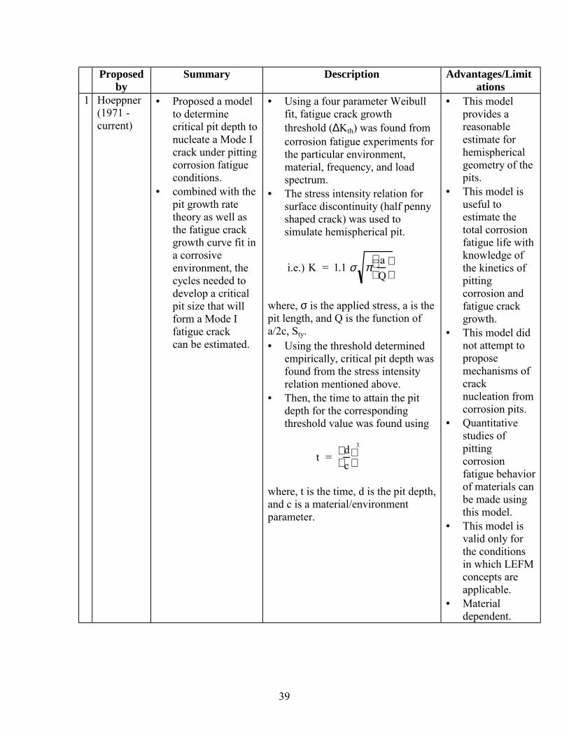
39
Proposedby
Summary Description Advantages/Limitations
1 Hoeppner(1971 -current)
• Proposed a modelto determinecritical pit depth tonucleate a Mode Icrack under pittingcorrosion fatigueconditions.
• combined with thepit growth ratetheory as well asthe fatigue crackgrowth curve fit ina corrosiveenvironment, thecycles needed todevelop a criticalpit size that willform a Mode Ifatigue crackcan be estimated.
• Using a four parameter Weibullfit, fatigue crack growththreshold (∆Kth) was found fromcorrosion fatigue experiments forthe particular environment,material, frequency, and loadspectrum.
• The stress intensity relation forsurface discontinuity (half pennyshaped crack) was used tosimulate hemispherical pit.
i.e.) K = 1.1 σ πaQ
where, σ is the applied stress, a is thepit length, and Q is the function ofa/2c, Sty.• Using the threshold determined
empirically, critical pit depth wasfound from the stress intensityrelation mentioned above.
• Then, the time to attain the pitdepth for the correspondingthreshold value was found using
t = dc
3
where, t is the time, d is the pit depth,and c is a material/environmentparameter.
• This modelprovides areasonableestimate forhemisphericalgeometry of thepits.
• This model isuseful toestimate thetotal corrosionfatigue life withknowledge ofthe kinetics ofpittingcorrosion andfatigue crackgrowth.
• This model didnot attempt toproposemechanisms ofcracknucleation fromcorrosion pits.
• Quantitativestudies ofpittingcorrosionfatigue behaviorof materials canbe made usingthis model.
• This model isvalid only forthe conditionsin which LEFMconcepts areapplicable.
• Materialdependent.

40
Proposedby
Summary Description Advantages/Limitations
2 Lindley etal. (1982)
• Similar toHoeppner’smodel, a methodfor determiningthe threshold atwhich fatiguecracks would growfrom the pits wasproposed.
• Pits were considered as semi-
elliptical shaped sharp cracks• Used Irwin’s stress intensity
solution for an elliptical crack inan infinite plate and came upwith the relationship to estimatethreshold stress intensity valuesrelated to fatigue cracknucleation at corrosion pits.i.e.)
∆Kth =
∆σ πa( ) 1.13 −0.07 ac( )
12
1 +1.47 ac( )1.64
12
where, ∆σ is the stress range, a isthe minor axis, and c is the majoraxis of a semi-elliptical crack.
• From the observed pit geometryi.e. for a/c ratio, threshold stressintensity can be calculated.
• For the corresponding a/c ratio,
critical pit depth can beestimated.
• The proposed
stress intensityrelation can beused in tension- tensionloadingsituationswhere stressintensity forpits and cracksare similar.
• Critical pit
depths forcrackedspecimens canbe estimatedusing theexistingthreshold stressintensity values.
• This model is
valid only forthe conditionsin which LEFMconcepts areapplicable.
• Material
dependent.

41
Proposedby
Summary Description Advantages/Limitations
3 Kawai andKasai(1985)
• Proposed a modelbased onestimation ofallowable stressesunder corrosionfatigue conditionswith emphasis onpitting.
• As corrosion is not
usually consideredin developing S-Nfatigue curves, amodel forallowable stressintensity thresholdinvolvingcorrosion fatigueconditions wasproposed.
• Considered corrosion pit as an
elliptical crack.• Based on experimental data
generated on stainless steel, newallowable stresses based onallowable stress intensitythreshold was proposed.
i.e.)
∆σall =∆kall
F πhmax
where, ∆Kall can be determined froma da/dN vs. ∆K plot for a material,hmax is the maximum pit depth, and Fis a geometric factor.
• Using this
model,allowable stressin relation tocorrosionfatiguethreshold as afunction of timecan beestimated.
• Material
dependent. • This model is
valid only forthe conditionsin which LEFMconcepts areapplicable.

42
Proposedby
Summary Description Advantages/Limitations
4 Kondo(1989)
• Corrosion fatiguelife of a materialcould bedetermined byestimating thecritical pitcondition usingstress intensityfactor relation aswell as the pitgrowth raterelation.
• Pit diameter was measuredintermittently during corrosionfatigue tests.
• From test results, corrosion pitgrowth law was expressed as
2c α Cp t1/3
where, 2c is the pit diameter, t is thetime, and Cp is anenvironment/material parameter.Then, critical pit condition (∆Kp) in
terms of stress intensity factorwas proposed by assuming pit asa crack.
∆Kp = 2.24σaπcα
Qwhere, σa is the stress amplitude, a isthe aspect ratio, and Q is the shapefactor.• Critical pit condition was
determined by the relationshipbetween the pit growth ratetheory and fatigue crack growthrates.
c = cp (N/f)1/3
where, N is the number of stresscycles, f is the frequency, and 2c isthe pit diameter.• The pit growth rate dc/dN was
developed using ∆K relation asgiven below.
dcdN =
13
Cp
3 f −1α 2π2Q−2 2.24σ a( )4 ∆K −4
dc/dN was determined usingexperimental parameter Cp.• Finally, the critical pit size 2Ccr
was calculated from the stressintensity factor relation.
i.e.) 2Ccr = (2Q/πα)( ∆Kp/2.24σa)2
• The aspect ratiowas assumed asconstant.
• Material andenvironmentdependent.
2.8 References
43
1. Jones, D., Principles and Prevention of Corrosion, Macmillan Publishing Co., N.Y.,1992, pg. 198.
2. Szklarska, S., Pitting Corrosion of Metals, published by National Association of
Corrosion Engineers (NACE), Houston, Texas, 1986, pg. 1. 3. Aluminum Properties and Physical Metallurgy, Ed., J.E. Hatch, American Society for
Metals (ASM), Metals Park, Ohio, 1984, pg. 253. 4. McAdam, D.J. and Gell, G.W., “Pitting and its Effect on the Fatigue Limit of Steels
Corroded Under Various Conditions,” Journal of the Proceedings of the AmericanSociety for Testing Materials, Vol. 41, 1928, pp. 696-732.
5. Foley, R.T., “Localized Corrosion of Aluminum Alloys - A Review,” Corrosion, Vol.
42, No. 5, 1986, pp. 277-288. 6. Grimes, L., A Comparative Study of Corrosion Pit Morphology in 7075-T6
Aluminum Alloy, M.S. Thesis, University of Utah, 1996. 7. Liversidge, “On the Corrosion of Aluminum,” Chemical News, LXXI, 1895. 8. Bengough and Hudson, “Aluminum, Fourth Report to the Corrosion Committee,”
Journal of the Institute of Metals, Vol. 21, No. 1, 1919, pg. 105. 9. Barnes and Shearer, “A Hydrogen Peroxide Cell,” Journal of physical chemistry, Vol.
12, 1908, pg. 155. 10. Dunstan and Hill, “The Passivity of Iron and Certain Other Metals,” Journal of the
Chemical Society, Vol. 99, 1911, pg. 1853. 11. Godard, The Corrosion of Light Metals, John Wiley and Sons, N.Y., 1967. 12. Hart, “The Oxidation of Aluminum in Dry and Humid Oxygen Atmospheres,” The
Proceedings of the Royal Society, A236, 1956, pg. 68. 13. Thompson, Shimizu, and Wood, “Observation of Flaws in Anodic Films on
Aluminum,” Nature, Vol. 286, 1980, pg. 471. 14. Hoar and Wood, “The Sealing of Porous Anodic Oxide Films on Aluminum,”
Electrochemica Acta, Vol. 7, 1962, pg. 333. 15. Seligman and Williams, “The Action on Aluminum of Hard Industrial Waters,”
Journal of the Institute of Metals, 23, 1920. 16. Alwitt, “The Growth of Hydrous Oxide Films on Aluminum,” Journal of the
Electrochemical Society, Vol. 121, No. 10, 1974, pp. 1322-1328.

44
17. Graedel, “Corrosion Mechanisms for Aluminum Exposed to the Atmosphere,”
Journal of the Electrochemical Society, Vol. 136, No. 4, 1989, pg. 204C. 18. Rozenfield and Danilov, “Electrochemical Aspects of Pitting Corrosion,” Corrosion
Science, Vol. 7, 1967, pg. 129. 19. Broli, A. and Holtan, H., “Use of Potentiokinetic Methods for the Determination of
Characteristic Potentials for Pitting Corrosion of Aluminum in a Deaerated Solutionof 3% NaCl,” Corrosion Science, Vol. 13, 1973, pp. 237-246.
20. Hoar, T.P., “The Production and Breakdown of the Passivity of Metals”, Corrosion
Science, Vol. 7, 1967, pp. 341-355. 21. Godard, The Corrosion of Light Metals, John Wiley and Sons, N.Y., 1967. 22. Dallek, S. and Foley, R.T., “Propagation of Pitting on Aluminum Alloys”, Journal of
the Electrochemical Society, Vol. 125, No. 5, 1978, pp. 731-733. 23. Nguyen, T.H. and Foley, R.T., “On the Mechanism of Pitting of Aluminum,” Journal
of the Electrochemical Society, Vol. 126, No. 11, 1979, pp. 1855-1860. 24. Baumgartner and Kaesche, “Aluminum Pitting in Chloride Solutions: Morphology
and Pit Growth Kinetics,” Corrosion Science, Vol. 31, 1990, pp. 231-236. 25. Ma, L., Pitting Effects on the Corrosion Fatigue Life of 7075-T6 Aluminum Alloy,
Dissertation, University of Utah, 1994. 26. Chen, G. S., Liao, C., Wan, K., Gao, M., and Wei, R. P., “Pitting Corrosion and
Fatigue Crack Nucleation,” Effects of the Environment on the Initiation of CrackGrowth, ASTM STP 1298, W. A. Van Der Sluys, R. S. Piascik, and R. Zawierucha,Eds., American Society for Testing and Materials, 1997, pp. 18-33.
27. Uhlig, H.H., “Adsorbed and Reaction-Product Films on Metals,” Journal of the
Electrochemical Society, Vol. 97, No. 11, 1950, pp. 215c-220c. 28. Bohni and Uhlig, H.H., “Environmental Factors Affecting the Critical Pitting
Potential of Aluminum,” Journal of the Electrochemical Society, Vol. 116, 1969, pp.906-910.
29. Leckie, H.P. and Uhlig, H.H., “Environmental Factors Affecting the Critical Potential
for Pitting in 18-8 Stainless Steel,” Journal of the Electrochemical Society, Vol. 113,No. 2, 1966, pp. 1262-1267.
30. Hoar, T.P. and Jacob, W.R., Nature, 216, 1967, pg. 1299.

45
31. Kolotyrkin, Ya, M., “Effects of Anions on the Dissolution Kinetics of Metals,”Journal of the Electrochemical Society, Vol. 108, No. 3, 1961, pp. 209-216.
32. Strehblow, H.H., Titze, B., and Loechel, B.P., “The Breakdown of Passivity of Iron
and Nickel by Flouride”, Corrosion Science, Vol. 19, 1979, pp. 1047-1057. 33. Bohni, H., “Localized corrosion,” in Corrosion Mechanisms, Ed., F. Mansfeld,
Marcel Dekker, Inc., N.Y., 1987, pp. 285-328. 34. Sato, N., “Anodic Breakdown of Passive Films on Metals”, and “The Stability of
Pitting Dissolution of Metals in Aqueous Solution,” Journal of the ElectrochemicalSociety, Vol. 129, No. 2, 1982, pp. 255-260 and 260-264.
35. Richardson and Wood, “A Study of the Pitting Corrosion of Al by Scanning Electron
Microscopy,” Corrosion Science, Vol. 10, 1970, pp. 313-323. 36. Nilsen, N. and Bardal, E., “Short Duration Tests and a New Criterion for
Characterization of Pitting Resistance of Al Alloys,” Corrosion Science, Vol. 17,1977, pp. 635-646.
37. Hoar, T.P. and Jacob, W.R., Nature, 216, 1967, pg. 1299. 38. Chao, Lin, and Macdonald, “A Point Defect Model for Anodic Passive Films I. Film
Growth Kinetics,” Journal of the Electrochemical Society, Vol. 128, No. 6, 1981, pp.1187-1194.
39. Lin, Chao, and Macdonald, “A Point Defect Model for Anodic Passive Films II.
Chemical Breakdown and Pit Initiation,” Journal of the Electrochemical Society, Vol.128, No. 6, 1981, pp. 1194-1198.
40. Sato, N., “Anodic Breakdown of Passive Films on Metals”, and “The Stability of
Pitting Dissolution of Metals in Aqueous Solution,” Journal of the ElectrochemicalSociety, Vol. 129, No. 2, 1982, pp. 255-260 and 260-264.
41. Richardson and Wood, “A Study of the Pitting Corrosion of Al by Scanning Electron
Microscopy,” Corrosion Science, Vol. 10, 1970, pp. 313-323. 42. Galvele, “Transport Processes and the Mechanism of Pitting of Metals,” Journal of
the Electrochemical Society, Vol. 123, No. 4, 1976, pp. 464-474. 43. Akid, R., “The role of stress-assisted localized corrosion in the development of short
fatigue cracks,” Effects of the Environment on the Initiation of Crack Growth, ASTMSTP 1298, W. A. Van Der Sluys, R. S. Piascik, and R. Zawierucha, Eds., AmericanSociety for Testing and Materials, 1997, pp. 3-17.
44. Hoeppner, D.W., “Corrosion Fatigue Considerations in Materials Selections and
Engineering Design,” in Corrosion Fatigue: Chemistry, Mechanics, and

46
Microstructure, O. Devereux, A.J. McEvily, R.W. Staehle, Eds., NACE-2, NationalAssociation of Corrosion Engineers,1972, pp. 3-11.
45. Hoeppner, D.W., “Model for Prediction of Fatigue Lives Based Upon a Pitting
Corrosion Fatigue Process,” Fatigue Mechanisms, Proceedings of an ASTM-NBS-NSF Symposium, J.T. Fong, Ed., ASTM STP 675, American Society for Testing andMaterials, 1979 pp. 841-870.
46. Lindley, T. C., McIntyre, P., and Trant, P. J., “Fatigue Crack Initiation at Corrosion
Pits,” Metals Technology, Vol. 9, 1982, pp. 135-142. 47. Kawai, S. and Kasai, K., “Considerations of Allowable Stress of Corrosion Fatigue
(Focused on the Influence of Pitting),” Fatigue Fracture of Engineering MaterialsStructure, Vol. 8, No. 2, 1985, pp. 115-127.
48. Kondo, Y., “Prediction of Fatigue Crack Initiation Life Based on Pit Growth,”
Corrosion Science, Vol. 45, No. 1, 1989, pp. 7-11. 49. Rebiere, M. and Magnin, T., Materials Science and Engineering, Vol. A128, 1990,
pg. 99. 50. Chen, G.S. and Duquette, D.J., “Corrosion Fatigue of a Precipitation-Hardened Al-Li-
Zr Alloy in a 0.5 M Sodium Chloride Solution,” Metallurgical Transactions, Vol. 23,1992, pp. 1563-1572.
51. Chen, G.S. et al., Corrosion, Vol. 52, 1996, pg. 8. 52. Hoeppner, D.W., Mann, and Weekes, “Fracture mechanics based modelling of
corrosion fatigue process,” in Corrosion Fatigue: Proceedings of the 52nd meeting ofthe AGARD Structural and Materials Panel held in Turkey, 5-10 April, 1981.
53. Ma, L., and Hoeppner, D. W., “The Effects of Pitting on Fatigue Crack Nucleation in
7075-T6 Aluminum Alloy,” Proceedings of the FAA/NASA International Symposiumon Advanced Structural Integrity Methods for Airframe Durability and DamageTolerance, NASA Conference Publication 3274, Part 1, 1994, pp. 425-440.

47
3 Microstructure and environment effects on “short” crack behavior of materials
3.1 Introduction
As the meaning of the word "short" as related to the formation and early
propagation of cracks differs significantly with respect to the conditions of interest (coi),
it has been realized by the technical community that there are three basic types of
"short"/"small" cracks viz. microstructurally-short-cracks, chemically-short-cracks, and
mechanically-short-cracks. This section discusses the mechanisms of “short” crack
formation as influenced by microstructure and environments as well as some studies on
crack formation from corrosion pits in the “short” crack regime.
Design of structural components using fracture mechanics concepts requires three
basic parameters viz. load or applied stress, stress intensity factor, and discontinuity or
crack size. Conventionally damage tolerant design methods consider an initial
discontinuity size typically in the order of 1 mm (0.04") while applying fracture
mechanics concepts to design damage tolerant components (Potter and Yee, 1983* ).
Fatigue crack growth tests in the "long" crack regime as per ASTM E647 are conducted
on materials that are to be used to make the damage tolerant parts and together with the
assumed initial discontinuity size as well as the appropriate loading and material
parameters safe inspection intervals are computed. However, the technical community has
realized the significance of the formation and existence of the so called "short" cracks
(examples: manufacturing discontinuities like crack(s) from a hole that may result from
improper riveting operation, and material microstructural discontinuities in the "short"
crack range, typically in the order of grain size, or less) and their growth is "faster" when
compared to "long" cracks in the equivalent or even at lower stress intensity range. With
the support of experimental studies conducted by several researchers to determine the
"short" crack behavior of materials, it can be argued that the current practice of
computing inspection intervals of aircraft critical structural parts using the "long" crack * References are listed in the alphabetical order of the principal authors at the end of the section.

48
growth data and the initial "flaw" size of 1 mm might lead to unexpected fatigue crack
growth behavior resulting in a catastrophic failure. This implies that designing
components using damage tolerant concepts may still not be safe when "short" crack
behavior is not integrated in fatigue life prediction methods. Moreover, the applicability
and the accuracy of the Linear Elastic Fracture Mechanics (LEFM) concepts in predicting
“short” crack behavior was addressed by several researchers in the Specialists Meeting
organized by AGARD (AGARD, 1983). "Small" cracks were found in aircraft fuselage
riveted lap joints (Schijve, 1992), fastener holes (Potter and Yee, 1983) and in tear-down
aircraft wing critical structures (Wood and Rudd, 1983).
Although many research studies were conducted, there is still not a clear
understanding among the researchers with regard to the usage of terminology such as
"small" and "short" as related to the size of the crack as these terms are often mixed up in
the literature and this alone exemplifies the complexity of the challenge we have at
present. However, many "short" crack researchers agree on the following aspects:
• There are three basic types of "short" cracks viz. mechanically or physically "short",
microstructurally "short" and chemically "short" (McClung, Chan, Hudak and
Davidson, 1994).
• "Short" cracks cannot be modeled using the Linear Elastic Fracture Mechanics
(LEFM) concepts although some workers have attempted to convert the "short" crack
data to "long" crack, to compare the crack growth behavior in both the regimes and
also to evaluate the "effective crack driving force" for "small" and "large" fatigue
cracks (Tokaji, Ogawa, Harada and Ando, 1986; Tokaji, Ogawa and Harada, 1987;
Davidson, 1988; Hyspecky and Stanadel, 1992; Nicholls and Martin, 1991; Sheldon,
Cook, Jones and Lankford, 1981).
• "Short" cracks often grow "rapidly" when compared to "long" cracks at a lower stress
intensity range that is below the "long" crack threshold and also at an equivalent stress
intensity range. In some materials, the "short" growth rate is observed to be much

49
"faster" than would be predicted by extrapolating "large" crack data (Lankford, 1982;
Lankford, 1985).
• The material parameters which influence plastic deformation; viz. grain size, grain
orientation, texture, work hardening rate, slip band character, local microscopic
fracture toughness, inclusion size and content as well as second phase particles have
an important role in "short" crack growth (Hoeppner, 1981 and Miller, 1982).
• Current NDI technologies are not capable of detecting the discontinuities that are in
the "short" crack range (Wood and Rudd, 1983). This directly affects the inspection
related issue as it is inextricably linked with the damage tolerant design concepts.
• There is no single parameter that can define the "short crack driving force".
• Although a few studies have attempted deterministic "short" crack growth prediction
methods for physically or mechanically "short" cracks, as the influence of the
microstructural variations on the "short" crack behavior of materials is extremely
complex, the challenge of incorporating "short" crack methodology into present
practice of fatigue life prediction analyses must be treated with probabilistic
approaches. This necessitates the study of scatter in the behavior of "small" cracks to
understand the physical basis of scatter in the fatigue lives of components or
specimens (Goto, 1992 and Goto, 1993).
Several researchers have postulated different mechanisms for the behavior of
"short" cracks. They are indeed related to the type of "short" cracks. For microstructurally
"short" cracks, "crack tip shielding" and "enhanced crack tip plastic strains" are stated to
be responsible phenomena (Ritchie and Lankford, 1986). Also, evidences suggest that
microstructurally "short" cracks are sometimes obstructed locally by grain boundaries
(crack arrest), influenced by non-uniform growth and sometimes may experience higher
cyclic plastic strains at the crack tips resulting in "faster" growth (Lankford, 1981,
Lankford, 1982, Ritchie and Suresh, 1995). Moreover, "short" cracks may be subjected to
"crack deflection" (Suresh, 1983) that may be related to the orientation of each grain.

50
Thus, texture has an important role in determining the behavior of microstructurally
"short" cracks.
Excessive plasticity is stated to be the mechanism for mechanically "short" cracks.
This implies that the assumption of "small-scale yield" that forms the basis of linear
elastic fracture mechanics is not applicable. Local crack tip environment (Gangloff, 1985)
has been hypothesized as a predominant mechanism for the "faster" propagation of
chemically "short" cracks as they are more vulnerable to chemical attack than "long"
cracks because of the relative ease of access to the crack tip. For physically "short"
cracks, it is hypothesized that the "crack closure effect" that decreases the "crack driving
force" for "long" crack propagation may be absent (Schijve, 1986). Furthermore, it is
believed that "short" cracks that are usually associated with a limited "wake" are less able
to develop the same magnitude of shielding as equivalent "long" cracks at the same
nominal stress intensity range (Lankford 1986). Some experimental studies have showed
that although the growth rate of microstructurally "short" cracks is "faster" initially, once
the crack tip reaches the grain boundary the growth rate either gets reduced or some times
completely arrested at the grain boundary (Lankford, 1982, Lankford, 1983, Lankford and
Davidson, 1986, Tokaji and Ogawa, 1992, Ritchie and Suresh, 1995).
Moreover, the dimension of the crack also is related to the types of crack.
Mechanically "short" crack size 'a' is considered to be less than the plastic zone size and
microstructurally "short" crack size is related to the grain size (Hoeppner, 1981; Ritchie
and Suresh, 1995). As the crack length is "short" compared to the microstructural
dimensions, such as the grain size, it has been realized that the assumption that the crack
grows in a homogeneous, isotropic continuum is no longer valid.
Therefore, the primary focus of this section is to review the present understanding
of the influence of microstructure and environment on the behavior of "short"/"small"
cracks in structural materials.

51
3.2 Effect of microstructure on the “short” crack behavior of materials
This section reviews microstructurally "short"/"small" crack studies conducted on
materials. The mechanisms of the "short" crack growth behavior as related to the local
microstructural variations and crack closure phenomena are discussed in detail.
When applying damage tolerance principles to the design of structural
components subjected to cyclic loading, a geometry independent parameter ∆K (stress
intensity range), is used to characterize the crack growth. This is the basis of Linear
Elastic Fracture Mechanics (LEFM). Moreover, it is presumed that cracks would not
propagate at a stress intensity below a threshold value and it is usually denoted as ∆Kth.
Although it has been realized that there is no geometry independent crack driving force in
the "short" crack regime, several attempts have been made to predict "short" crack growth
rates including some approaches that are based on crack deflection, crack closure, 'J'
integral and some semi-empirical methods (Hoeppner and Cameron; Morris and Buck,
1977, McEvily and Minakawa, 1984, Suresh, 1985, and El Haddad, Dowling, Topper,
and Smith, 1980). As microstructure has varying effects in materials, it has been realized
that the deterministic way of fatigue life prediction in the "short" crack regime is far from
accurate. A need for the development of probabilistic concepts and models to solve the
“short” crack challenges was emphasized by Hoeppner (1983). However, some
researchers have proposed models which incorporate microstructural parameters into the
"short" crack growth rate equations (Petit and Zeghloul, 1986, Petit and Zeghloul, 1990)
A distinction between "small" and "short" crack growth behavior was made by
some researchers (Lankford and Davidson, 1986, Breat, Mudry, and Pineau, 1983) by
experimental studies. Their studies have shown that the experimentally measured
difference in crack closure response between "short" and "large" cracks in A508 steel may
be sufficient to explain differences in their crack propagation behavior. From
experimental studies conducted in A508 steel, it was observed that da/dN versus ∆K for
52
"short" cracks was only an extension of the "long" crack behavior into the subthreshold
regime (Breat, Mudry, and Pineau, 1983). However, "small" cracks are related to a
controlling microstructural element, usually the grain size, and these cracks are observed
to be distinct from "short" cracks, i.e., through thickness cracks (0.5-2.0 mm) in length.
(Taylor and Knott, 1981) have suggested that the "small" crack regime corresponds
roughly to microcracks such that 2a = 10 GS where GS is grain size. Also, (Breat, Mudry,
and Pineau, 1983) have showed that "short" cracks do not grow much faster at a given ∆K
than do "long" cracks. But "short" cracks have a lower threshold, above which they
follow roughly the same da/dN versus ∆K curve that a "long" crack would if it were
simply to continue growing below its threshold. However, "small" cracks, as
hypothesized by these researchers, not only grow below ∆Kth, they also grow much faster
than would be predicted by extrapolating long crack results below their threshold. Some
studies (Taylor and Knott, 1981, Hicks and Brown, 1984, Lankford and Davidson, 1986)
have showed that "small" crack growth converges with the "large" crack curve when
plastic zone size is approximately equal to the grain size. This phenomenon has been
observed in aluminum alloy, fine grained, coarse grained and single crystal astroloy, and
p/m aluminum alloy.
In many cases it has been shown that the arrest or retardation of small cracks
correlates with the crossing of grain boundaries (Lankford, 1982, Lankford 1985). It also
has been postulated that if the plastic zone size is less than the grain size such crossings
are infrequent. In comparison with the "large" cracks, cracks are observed to grow in
many unfavorable grains simultaneously, hence, the average rate of growth is much lower
than that for "small" cracks at equivalent ∆K levels in favorably oriented grains. Although
these studies attempted to distinguish "small" and "short" cracks, many of the researchers
used the terminology in a mixed manner. Therefore, as the purpose of this report is only
to review the present understanding with regard to the fundamental issues pertaining to

53
microstructural and environmental aspects of the fatigue crack formation and growth, this
report includes the terms "short" and "small" as they are extracted from the literature.
In general, the "faster" growth of microstructurally "small" fatigue cracks
has been observed to be associated with second phase particles (Pearson, 1975), inclusion
particle clusters or voids (Newman and Edwards, 1988), eutectic colony boundaries
(Taylor and Knott, 1981), and grain boundaries (Lankford, 1985).
Early in 1975, bending fatigue studies were performed on commercial
aluminum alloys viz. aluminum-copper-magnesium (BS L65) and DTD 5050 (aluminum-
zinc-magnesium) (Pearson, 1975). It was observed that cracks in the order of, or even less
than, the grain size grew "faster" than "long" cracks. i.e. the mean crack growth rate in the
early stage was observed to be 1.27 X 10⁻⁶ mm (5 X 10⁻⁸ in.). In this study crack formed
at surface inclusions and it was related to previous cold working that was performed on
the material. Fracture mechanics approach was used to calculate ∆K values for "short"
and "long" cracks because the plastic zone size was observed to be 1/20th of the crack
length. Also, it was concluded that the growth rates in the early stage was much "faster"
than would be predicted from the "long" crack data.
Following this study, in 1976, uniaxial fatigue loads were applied on Aluminum
alloy 2219-T851 parallel to the rolling direction in room temperature and it was observed
that crack nucleated at the surface at intermetallic inclusions (Morris, Buck and Marcus,
1976). Moreover, it was showed that at the fatigue loads that are less than 0.6 times the
yield stress several cracks coalesced to form a macrocrack that lead to the ultimate
failure. The most important finding of this study showed that there was significant
retardation of microcracks with grain boundaries. Similar observation was made in
another study (Lankford, Cook and Sheldon, 1981), in that it was hypothesized that
"small" cracks grew "rapidly" during the initial stage and when the crack tip interacted
with grain boundaries, the growth rate slowed down. However, it also was formulated
that as the crack moved away from the boundary, the crack growth became "faster" again.

54
This behavior was related to local microplasticity in certain preferentially oriented grains
(Lankford, 1982). This study was conducted in laboratory air in 7075-T6 (precipitation
hardened aluminum) with 60% humidity. It was observed that for the "smallest" crack
(2a<40 µm), da/dN did not increase monotonically with ∆K. However, there was a
decrease in the crack growth rate and reached a minimum in the range 30 µm < 2a < 40
µm. Some of the cracks were found to be "nonpropagating". It was concluded that "small"
cracks could become "large" cracks "when their LEFM plastic zones begin to exceed in
size the maximum grain dimension".
Similar observation was made when "small" crack behavior was studied in A286
steel in which the "short" crack effect disappeared when the crack-tip plastic zone size
became greater than the grain size (Mei and Morris, 1993). This study also supported the
hypothesis that peak stress and microstructural effects in addition to the absence of crack
closure are some of the factors that influence the "short" crack growth in this material. In
another study, it was observed that when the applied stress was sufficiently high the
"short" crack growth rate could be sustained and could overcome the microstructural
barrier when tested in plain specimens (Pan, De Los Rios and Miller, 1993). Also, in this
study, tests on notched specimens (8090 Al-Li alloy) revealed that the extent of notch tip
and crack tip plastic zones control "short" crack propagation. It was hypothesized that "a
short crack will continue to propagate only if its own plastic zone can sustain growth as
the crack tip extends beyond the notch zone". Also, the effects of grain boundary, viz.,
changing the direction of the crack, temporary stopping of a crack, and forcing the crack
to adopt a zig-zag path were observed.
In SiC reinforced aluminum alloy (6061), "short" cracks were found to propagate
through the SiC particles as the crack front fractured the particles (Kumai, King and
Knott, 1990). In another study, the presence of voids in an overaged 2024 aluminum alloy
was observed to be responsible for the formation of fatigue "micro cracks" (Sigler,
Montpetit and Haworth, 1983). In this study, the density of microcracks (cracks were

55
counted when the size was more than 5 µm) was observed at different stress amplitudes
during the fatigue life. It was found to be 300/mm2 at 320 MPa, in 771 cycles at failure,
but less than 0.5/mm2 at 200 MPa, in 1.5X10⁵ cycles (at failure). This result has very
high significance as related to the possibility of microcracks coalescence into
macrocracks that may affect the ultimate fatigue life.
In nodular cast iron, "short" cracks formed from either the graphite nodules or
microshrinkage pores (Clement, Angeli and Pineau, 1984). Crack closure effect was
suggested as the mechanism for the "faster" growth of the "short" cracks for the given
stress intensity factor. On the other hand, in a medium carbon steel, the "short" crack
growth rate was related to the intensity and the extent of plasticity of the crack tip (De
Los Rios, Tang and Miller, 1984). Also, it was observed that "short" crack growth
decreased or even arrested at ferrite-pearlite boundaries. However, as the stress level was
increased to certain value, the two of the arrested cracks at the ends of the ferrite joined
up and the resultant crack branched off along the prior austenite grain boundaries.
Therefore, it was suggested that the critical fracture occurred when two of the "short"
cracks joined and branched that made it possible to propagate into the pearlite. Similar
hypothesis can be postulated for a "short" crack nucleating from corrosion pit in
aluminum alloys and the stress concentration of the pit may be sufficient for "short" crack
to overcome the grain boundary barrier for subsequent propagation. It can be further
hypothesized that if cracks form from adjacent pits these "short" cracks can join and may
grow "faster" when compared to "microcracks" coalescence resulting from other
microstructural heterogeneities. However, there are no experimental data to support this
theory and the very possibility of this occurring in a material should be investigated.
"Small" surface crack (2 to 1000 µm) studies on other materials like aluminum-
lithium alloy 2090-T8E41 also have shown an accelerated growth at ∆K levels as low as
0.7 MPa √m (Venkateswara Rao, Yu and Ritchie, 1988) and this behavior was related to
56
restrictions in the development of "crack tip shielding" resulting from "roughness-induced
crack closure".
In low carbon steel, when fatigue tested with specimens produced with two ferrite
grain sizes of 24 and 84 µm, it was found that in fine grained material most of the cracks
formed within ferrite grains and in coarse grained material the cracks formed at grain
boundaries (Tokaji, Ogawa and Harada, 1986). The most important finding of this study
was that the effect of grain boundary strongly depended on "short" crack length. For fine
and coarse grained material, when 2c>200 µm and 2c>250 µm respectively, the grain
boundary was not a barrier for the "short" crack propagation and dc/dN increased with
increasing crack length. Also, other studies showed that the effect of a grain boundary on
the "short" crack growth appeared to be dependent on the orientation of ferrite grains
(Lankford, 1985 and Suresh and Ritchie, 1984). In general, it has been recognized that
when cracks are of a length comparable to the scale of the microstructure, the growth is
greatly affected by the microstructure and the relevance of continuum mechanics is
limited. The concept of "microstructural dissimilitude" was proposed to explain this kind
of behavior (Chan and Lankford, 1988).
During the growth of "short" cracks, if the crack front behaves in a similar fashion
when it intersects many grains irrespective of the crack length, these cracks are believed
to possess similitude and the stress intensity range (corrected for yielding) can be used to
correlate the crack growth rates. However, for "short" cracks, it has been observed that
there is no linear relation between da/dN and ∆K. Thus, the challenge becomes so
complex as it is highly impossible to predict the potential site of crack nucleation that
may be related to the preferred orientation of the grain for the cracks to form. More
importantly, because of the greater dependence of the "short" crack challenge on the
microstructural variations in a material that is frequently in the order of a grain size, the
"short" crack problem is intrinsically statistical in nature (Hoeppner, 1981). Therefore, to
improve the resistance of the material microstructure to the nucleation of "short" fatigue

57
cracks, alloy design incorporating "small" randomly oriented grains, and texture to have
only a few grains as possible for an easy crack growth under a known loading condition
was suggested to be a useful way to deal with this issue (Ritchie and Lankford 1984).
Also, the challenge becomes still more complex as the local fracture toughness of each
grain is of practical significance as related to the formation and the propagation of cracks
in the "short" regime.
The effect of processing techniques on the "short" crack behavior was studied in
an aluminum-magnesium-silicon alloy (Plumtree and O'Connor, 1991) in strain control.
"Short" cracks were observed to form from second phase particles and the growth was
impeded at grain boundaries. It was concluded that the extruded alloy with a finer
microstructure and smaller second phase particles demonstrated a superior resistance to
formation of "short" cracks when compared to squeeze-cast material. "Short" cracks in
the order of 3 to 147 µm were found to form from Ti3Al hcp alpha phase in a titanium
aluminide alloy (Davidson, Cambell and Page, 1991). The results showed that the growth
of "small" cracks in titanium aluminide alloy was slower by a factor of 10 to 100 when
compared to aluminum alloys.
As the grain size has an important role in the behavior of microstructurally "short"
cracks, a study was conducted to demonstrate the effect of grain size on the "short"
fatigue cracks. Specimens from 7075-T6 were prepared to produce grain sizes of 12 and
130 µm. Growth rates of surface cracks in the order of 20 to 500 µm were studied during
the axial fatigue test in laboratory air of 45 to 60% RH (Zurek, James and Morris, 1982).
It was found that the mechanism for the "short" crack growth behavior was dependent on
alloy grain size.
As discussed so far, many of the published works on the behavior of "short"
cracks indicate that grain boundaries impede propagation, resulting in decrease in the
growth rate or complete arrest in some cases. This kind of behavior has been modeled by
some workers (Eastabrook, 1984, Hobson, 1982, Lankford, 1982). These models predict
58
that increasing grain size will lead to faster crack propagation rates in the "short" crack
regime. (Brown, King, and Hicks, 1984) supported this model when they conducted
"short" crack studies on a Ni-base superalloy, Astroloy, with grain sizes of 12 and 50
micrometer. They observed slower crack propagation rates in the fine grained material
than those in the coarse grain size. Also, (Wagner, Gregory, Gysler, and Lutjering, 1986)
showed a similar trend in Ti-8.6Al alloy with grain sizes of 20 and 100 µm. In addition,
some studies (Hirose and Fine, 1983) reported slower growth in a powder metallurgy
aluminum alloy with a fine grain size. However, a different behavior was observed (Taira,
Tanaka, and Hoshina, 1979) in a 0.2% C steel with a ferrite/pearlite microstructure. They
observed similar growth rates at ferrite grain sizes of 20.5 and 55 µm and lower growth
rates only when the grain size was reduced to 7.8 µm. In contrast to these results are those
of (Brown and Taylor, 1984, and Zurek, James and Morris, 1982). Their studies (Brown
and Taylor, 1984) in a mill annealed alpha/beta titanium alloy (Ti-6Al-4V) with grain
sizes of 4.7 and 11.7 µm, could not detect any grain size effect. Also, (Zurek, James and
Morris, 1982) in 7075-T6 aluminum alloy, observed a decrease in growth rate with
increasing grain size from 12 to 130 µm. Thus, much of the published work on the effect
of grain size on "small" fatigue crack growth indicates that increasing grain size leads to
"faster" crack growth rates. In the microstructurally "small" crack regime, this trend is
related to the difference in the "blocking effect" of grain boundaries. This so called
"blocking effect" was observed to occur more frequently in fine grained material than in
coarse grained material. As demonstrated (Tokaji, Ogawa, Harada and Ando, 1986) in
quenched and tempered steel, prior austenite grain boundaries act as barriers to the
growth of microstructurally "short" cracks. It was observed in fine and coarse grained
materials.
The effect of variation of precipitate sizes on the "short" crack behavior was
studied (Brown, King and Hicks, 1984) using Astroloy with 50 µm grain size. In this
study, they investigated a range of gamma prime distributions, achieved by different heat-

59
treatment processes and they found similar "short" crack growth rates in all conditions.
Also, similar observation was made in a nickel base super alloy, Waspaloy, with about
the same grain size, but somewhat lower gamma prime volume fraction. It also was
realized by some investigators that one of the important ways of controlling short crack
behavior in steels and titanium alloys was through variations in the distribution and
proportions of the phases present. (De los Rios, Tang and Miller, 1984) When tested in a
0.4% C steel with a strongly banded structure with alternate layers of alpha and pearlite,
observed cracks nucleating in the alpha and were held up by the alpha/pearlite interfaces
and sometimes the propagation was completely stopped after reaching these boundaries.
Also, in another study using the same material (De los Rios, Mohamed and Miller, 1985),
but with a different microstructure in which the alpha outlined the prior austenite
(gamma) grain boundaries, the similar observation was made.
In 0.37% C steel (Hoshide, Yamada, Fujimura, 1985), with an alpha/pearlite
microstructure in two conditions, air-cooled from 865°C and furnace-cooled from 940°C,
cracks formed in the alpha/pearlite boundaries and stopped when the cracks reached the
pearlite. Also, slower "short" crack growth rates were presented in the air-cooled material
with the finer distribution of alpha. In one of the earlier studies (Kunio and Yamada,
1979) using martensite steel (alpha prime/ferrite alpha mixtures consisting of about 50
volume % of each), crack formation occurred in the alpha and growth stopped on
reaching alpha prime. However, it was found that at higher stress levels these cracks
continued to propagate, but until they reached lengths of 400-500 µm, their growth was
still impeded by regions of alpha prime. From these studies, in steels, it was clearly
observed that the presence of harder phases forced the cracks to take a tortuous path by
deflecting the crack paths. Similar study was carried out in titanium alloys (Hicks and
Brown, 1984). They compared the behavior of a beta processed titanium alloy, IMI 685,
with a coarse aligned alpha structure with that of alpha/beta heat-treated IMI 318. The
changes in orientation of the alpha plates at the prior beta grain boundaries and the coarse
60
beta grain sizes produced at the high beta heat-treated proved to be the main barriers to
"short" crack propagation in the IMI 685. However, in IMI 318 which consisted of
regions of primary alpha and transformed beta, cracks formed in the alpha and were
impeded by the harder regions of transformed beta, thereby meeting the effective barriers
at lengths very much shorter than the prior beta grain size. A five-fold difference in
average growth rate was obtained between the two microstructures.
Also, another study in IMI 318 and IMI 550 with different heat-treatment
processes (Boilngbroke and King, 1986) clearly showed that a finer and harder
transformed beta impedes the crack growth more effectively than a coarser transformed
beta produced at a slower cooling rate. Moreover, they showed that an average "short"
crack growth rates in the beta heat-treated structure are up to an order of magnitude faster
than in an alpha/beta heat-treated condition in IMI 318. Similar observations were made
in dual phase steels with ferrite and martensite phases, crack growth rates and crack path
were strongly affected by martensite phase (Minakawa, Matsuo, and Mcevily, 1982,
Dutta, Suresh, and Ritchie, 1984, and Shang, Tzou, and Ritchie, 1987). Somewhat similar
research observations also were presented (Tokaji and Ogawa, 1988) in medium carbon
steel and dual-phase stainless steel. It also was found that as cracks grew into pearlite
phase from ferrite phase in medium carbon steel and austenite phase from ferrite phase in
dual-phase stainless steel, crack growth rates showed a marked decrease at phase
interfaces. Also, it was observed that cracks tend to grow predominantly within ferrite
phase in medium carbon steel. Fatigue crack was also found to form in softer ferrite in C-
Mn steel (de los Rios, Navarro, and Hussain, 1992). Moreover, (Kawachi, Yamada, and
Kunio, 1992) showed the possibility of coalescence of "small" cracks in a dual-phase
(martensitic-ferritic) carbon steel and as a result of this, cracks increased their length
along the matrix-ferrite, by-passing the harder martensite. They also demonstrated that the
crack coalescence could be suppressed in this kind of steel by preparing a dual phase

61
microstructure with the matrix ferrite enclosed by the second phase martensite. This
resulted in increase in the fatigue strength of this steel.
Also, other microstructurally "short" crack studies in different metals viz.
low carbon steel (Tokaji, Ogawa, and Harada, 1986), medium carbon steel (Tokaji and
Ogawa, 1988), high tensile steel (Tokaji, Ogawa, and Harada, 1987), low alloy steel
(Tokaji, Ogawa, Harada and Ando, 1986), aluminum alloy (Tokaji and Ogawa, 1990),
and pure titanium (Tokaji, Ogawa, Kameyama, and Kato, 1990) revealed a similar overall
growth behavior as crack growth rates were markedly decreased by grain boundaries,
triple pints and interfaces between phases depending on the microstructures. These
studies also supported the above mentioned research works that large decreases in
microstructurally "short" crack growth rate are more frequent in fine grained materials
than in coarse grained materials. This was observed to increase the overall fatigue life in
the fine grained materials.
In fine and coarse grained materials such as in pure titanium (Tokaji, Ogawa,
Kameyama, and Kato, 1990), the crack path was observed to be extremely tortuous and it
increased with increase in grain size. Therefore, decrease in crack growth rate resulted. It
also was shown that decrease in crack growth rate were more frequently observed in fine
grained material as compared to coarse grained material. This was attributed to grain
boundary and crack deflection. As described in one study (Suresh, 1983), the deflection in
crack path might lower the crack driving force. Also, as hypothesized by some
researchers (Tokaji and Ogawa, 1992), the tortuous nature of crack path morphology in
pure titanium might be associated with planar slip characteristics or fewer slip systems
than bcc and fcc metals. Furthermore, they postulated that because of this, as cracks
reached grain boundary, large changes of growth direction might occur due to the
incompatibility of deformation and it was related to misorientation between two grains.
Although extensive research studies on the microstructurally "short" crack behavior were
performed on various possible materials, a direct comparison is not possible because of
62
some obvious differences in test conditions viz. stress level, loading type and other test
parameters. However, as indicated before, a general behavior of microstructurally "short"
cracks is observed in many of the materials bearing a few contradictory results.
The effect of stress ratio (R) on microstructurally "short" cracks was studied by
some workers (Tokaji and Ogawa, 1990). In aluminum alloy (7075-T6) tested at R=-1
and R=0, faster growth was recorded at R=-1. Also, the results at R=-2 showed the fastest
crack growth rates. (Tokaji and Ogawa, 1992) observed stage I facets on the fracture
surfaces when tested at R=-1 and R=-2 but not at R=0. They related the growth behavior
of microstructurally "short" cracks to the existence of stage I facets. Also, some studies
on Stage I crack formation as related to "short" crack growth behavior are discussed in the
next section.
3.3 Stage I crack propagation studies and its relation to "short" crack growth behavior
The slip mechanism for the formation of fatigue cracks was first studied by Ewing
and Humphrey, Gough and Forsyth among others. Since then, formation of persistent slip
bands (PSB) has been recognized as a general phenomenon for the nucleation of fatigue
cracks. Forsyth termed the formation and growth of crack in slip bands during the fatigue
process as Stage I. Stage I or slip band cracking was related to the range of resolved shear
stress on the slip plane (Hoeppner, 1967 and Forsyth, 1969). Also, slip bands produced by
cyclic stress were shown to be a series of grooves and ridges and the fatigue deformation
mechanism of "slip band intrusion and extrusion" was related to Stage I crack growth
mechanism (Forsyth, 1969). However, not all the fatigue cracks form from slip bands.
Under favorable conditions of stress and environment these cracks may form on those
planes most closely aligned with the maximum shear-stress directions in the component
or test specimens. Some "short" crack research studies related the behavior of cracks in
the "short" regime to Stage I cracks and they are discussed below.
63
Two high strength and low alloy steel containing V and Nb were fatigue tested to
observe the nucleation of cracks and growth of "microcracks" (Kim and Fine, 1982).
Strain controlled fatigue tests were conducted in 30-40% humidity air at room
temperature. Also, results of crack formation at different mean stress were reported. This
study showed that at all stress levels, fatigue cracks were observed to form along
persistent slip bands. The number of cycles to nucleate a crack of size 5 µm long was
observed at 2000 to 3000 magnification and the "microcracks" were always found to be
associated with slip bands. (Kwun and Fournelle, 1982) also reported more density of slip
bands and "small" cracks for quenched and tempered at a lower temperature when
compared to tempering performed at higher temperature in Niobium bearing high strength
and low alloy steel.
Although the formation of cracks in extruded aluminum alloy X7091 containing
Zn-Mg-Cu and Co occurred at grain boundaries at both low and high stresses, the same
was not true when the material was subjected to thermomechanical treatment. This
resulted in the slip band crack nucleation (Hirose and Fine, 1983). Another study (Kim,
Mura and Fine, 1978) in 4140 steel also showed that "microcracks" formed at grain
boundaries in as-quenched specimens and at intrusions and extrusions in the tempered
specimens.
In another study, Tokaji and Ogawa, 1988, observed many straight lines on the
facets of medium carbon steel and the direction of these lines were confirmed to be
consistent with the slip direction <111> of this material. This indicated that the crack
grew along slip planes in a shear mode and it was related to stage I crack growth
mechanism. Moreover, they (Tokaji and Ogawa, 1992) argued that the microstructural
effect "short" crack growth occurred as a sequence of stage I crack growth.
At higher strains, at two different microstructures, when fatigue tested, Ti-6Al-
2Sn-4Zr-6Mo exhibited nucleation of cracks within the slip bands in Widmanstatten plus
grain boundary alpha and equiaxed structures of different alpha particle (Mahajan and
64
Margolin, 1980). However, at low strains the crack nucleation occurred at alpha-beta
interface and the resultant "microcracks" linked up and extended.
Similar observation was made in another study conducted in 2024 and 2124
aluminum alloy in the T-4 condition (Kung and Fine, 1979). This study was conducted in
dehumidified laboratory air, 10% humidity as well as 50% humidity. The loading was
applied in tension-tension and also in tension-compression with the direction of stress
normal to the long direction of the notch and parallel to the specimens rolling direction. It
was found that at high stresses the fatigue cracks formed on "coarse slip lines" in both
alloys. However, at low stresses majority of cracks originated from the constituent
particles. However, the important finding of this study was the probability of nucleation
of a fatigue crack at a constituent particle size normal to the stress direction decreased
below 6 µm and the crack formation mode was along slip bands which originated from
the inclusions.
Polycrystalline copper of commercial purity (99.9%) exhibited formation of
extrusions and intrusions along persistent slip bands within the grain and also in
preferably oriented grain boundaries when tested in constant strain amplitude cyclic
loading (Polak and Liskutin, 1990). "Short" crack growth was characterized by PSB
nucleation and was related to localization of the cyclic slip at or close to grain boundaries
and "the cracks advanced by linking a newly nucleated crack at the tip of the existing
crack or in front of it" (Plumtree and O'Connor, 1991) also observed the stage I crack
growth to a depth of about 250-350 µm in Al-Mg-Si alloy subjected to two different
processing techniques viz. extruded and squeeze-cast. They stated that the "short" crack
behavior was observed during this portion of fatigue life.
Different kinds of crack nucleation mechanisms were observed in nickel base
super alloy namely, Waspaloy (Yates, Zhang and Miller, 1993). Four point bending
fatigue tests were conducted on Waspaloy specimens and was found that crack formed
directly from PSBs, along a twin boundary and also in grains. Moreover, it was observed

65
that in all the three types, cracks formed at 45° to the principal stress axis suggesting the
Stage I growth until the crack depth of around 600 µm. This study proposed a model for
the "short" crack growth behavior in Waspaloy incorporating the microstructural effect as
well as the characteristic nature of grain boundary in blocking the growth of "short"
cracks.
3.4 Environment effects on "short" crack behavior of materials
The environment (chemical) and temperature effects on the fatigue crack
propagation in the "long" crack regime are not well understood and the same is applicable
to "short" crack studies. Very few researchers have performed "short" crack studies to
evaluate these issues.
In an earlier study, very low environmental influence on "small" surface cracks
was observed in a 7075-T651 alloy when tested in ambient air and in purified nitrogen (2
ppm water) (Lankford, 1983). However, some studies (Zeghloul and Petit, 1985, Petit and
Zeghloul, 1986) have shown a greater effect of environment on the propagation of "short"
through cracks grown in a 7075-T651 and T7351 when tested in air and in purified
nitrogen and also the test results were compared in vacuum. Moreover, in another study
(Petit and Zeghloul, 1990), faster growth rate of "small" surface cracks was observed in
ambient air compared to vacuum when 7075-T651 and T7351 were fatigue tested. This
behavior was related to water vapor embrittlement as in the case of long cracks. These
studies have shown that the growth in ambient air of stage II cracks in a 7075 alloy can be
rationalized with that of long and "short" through-section cracks in terms of ∆Keff after
correction for local plasticity. However, another study (Petit and Kosche, 1992), showed
that the initial propagation in vacuum of "small" surface cracks naturally "initiated" on
smooth specimens in 7075-T651 and 7075-T351 alloys is much faster than stage II

66
propagation, and is similar to the intrinsic stage I regime, as identified on Al-Zn-Mg
single crystals.
More dramatic results were shown in a review paper (Gangloff and Wei, 1986) in
which it was concluded that "small" corrosion fatigue cracks in high strength steels when
cycled in aqueous hydrogen producing environments grew up to 500 times faster than
"long" crack at constant ∆K.
Another study (Akid and Murtaza, 1992) showed that environmental assisted
"short" fatigue crack growth could influence the propagation of cracks beyond the "crack-
arresting barriers" such as grain boundaries. Their studies in high strength spring steel
using an intermittent fatigue tests in air and NaCl solution clearly showed that strain
assisted dissolution caused the transition of stage I crack to stage II at shorter crack
lengths. Also, (Boukerrou and Cottis, 1992), another study in a structural steel (BS4340
grade) in 3.5% NaCl and in pitting solution, showed that cracks could nucleate from
corrosion pits when cycled at low stresses.
3.5 Temperature effects on "short" crack behavior of materials
At room temperature, "short" cracks were found to form primarily at inclusion
particles, and less frequently at grain boundaries in Nickel base super alloy when
cyclically loaded in four point bending specimens (Mei, Krenn, and Morris, 1993).
However, when tested at elevated temperature (873°K) "short" cracks were observed to
form from micropores, slip planes and carbide precipitates at grain boundaries in Nickel
base super alloy (Okazaki, Tabata and Nohmi, 1990). In this study, Stage I fatigue
fracture occurred on the {111} planes. Also, (Stephens, Grobowski and Hoeppner, 1993)
slip band cracking was observed in Waspaloy tested at 25°C, 500°C and crack was
observed to form at twin boundaries and slip bands at 700°C. Moreover, this study
demonstrated the "faster" growth rate of "short" cracks at 500°C when compared to 25°C
67
and 700°C. This was related to diffusive nature of slip bands and "changes in material
leading to precipitate coarsening" at 700°C. Similar observation of slip band cracking was
found in Waspaloy when tested at 19°C and 500°C (Healy, Grabowski and Beevers,
1991). In addition, "short" cracks formed at coarse carbide particles. The "short" crack
growth rate measured at R=0.1 was "faster" at 500°C when compared to 19°C at an
equivalent values of stress intensity range as reported by Stephens, Grobowski and
Hoeppner. In another study (Suh, Lee and Kang, 1990), numerous "microcracks" were
observed to form at grain boundaries in 304 stainless steel specimens tested at 538°C.
In general, the mechanisms for the "short" crack behavior at room and elevated
temperature as postulated in the above mentioned studies are related to
• absence of closure effects,
• heterogeneous microstructure (responsible for statistical scatter in the "short" crack
growth rate (Goto, 1993; Goto, 1994)),
• grain boundary cracking (may result from embrittlement due to stress-assisted grain
boundary oxidation during heat treatment),
• grain orientation (if the grains are favorably oriented the cracks are observed to grow
"faster" and if not "short" crack growth either gets slowed down or arrested),
• crack deflection (may occur within a grain or when the crack passed to another grain),
• crack tip deflection resulting in "roughness induced crack closure" and subsequent
reduction in crack growth rate,
• Stage I crack growth (Stage I crack growth increases as the crack length increases.
However, as the crack tip neared a grain boundary the "short" crack growth rate decreased
because of crack deflection due to secondary slip and finally fracture occurring on the
{111} planes in fcc).
68
3.6 Studies on transition of pit to “small” crack
A few “small” crack studies under corrosion fatigue conditions have been
performed to characterize the transition of a pit to a “small” crack. In 2024 aluminum
alloy, Piascik and Willard have shown a three times increase in crack growth rates of
“small” cracks in salt water environment when compared to air. Moreover, their studies
clearly have observed the transition of pits formed at the constituent particles to
intergranular “microcracks” and then to transgranular fracture path once the crack reaches
the depth of 100 mm. In addition, the increase in “small” crack growth rates was observed
even at very low mode I ∆K (<1 MPa √m). As well, Kondo (1989) also observed in two
low alloy steels that “short” cracks from pits propagated at ∆K that is well below the
threshold value of a long crack for these materials.
In a recent in-situ fatigue study, prior pitted 2024-T351 and 7075-T651 aluminum
alloy specimens exhibited faster crack growth rates in the “short” crack regime when
compared to specimens without prior corrosion damage (A. Hoeppner (now A. Taylor)
1996). This study showed that prior corrosion damage did influence the “small” crack
growth rates. It also was observed that the 7075 aluminum alloy specimen had faster
crack growth rates compared to the 2024 aluminum alloy specimens. Also, in this study
cracks were observed to form from pits on the prior corroded specimens whereas on the
specimens without any prior corrosion damage, cracks formed from constituent particles.
3.7 Conclusion
This literature review on microstructural and environmental effects of "short"
crack behavior of structural materials has clearly revealed the lack of experimental studies
to characterize materials response in the "short" crack regime under fretting fatigue and
corrosion conditions. As mentioned in this report, very little data have been published

69
with regard to "short" crack formation mechanisms in corrosive environments of
aluminum alloys in aircraft structures. In addition to a few previous studies (Hoeppner,
1971, 1979) in which pitting was modeled statistically with different materials and
specimen types, recently, as discussed before in this report, there was a study
demonstrating corrosion fatigue induced "short" crack formation from pits (Akid and
Murtaza, 1992). Also, recent studies (Ma and D. Hoeppner, 1994, Grimes, 1996, and A.
Hoeppner, 1996) have shown that pits form in different shapes depending upon
environment and loading conditions in contradictory to general assumption that pits have
hemispherical shape. Although this assumption simplifies the modeling part of research
(Kondo, 1989), further studies to characterize the formation of cracks from pits in the
"short" crack regime must be evaluated as indicated by A. Hoeppner (1996). Apart from
these studies the literature search has not found any "short" crack studies to evaluate the
formation of cracks from pits and their crack morphologies and paths. Moreover, this may
further be aggravated by fretting mechanism(s) in conjunction with fatigue and corrosion.
To conclude this section, a global view of the "short" crack challenge is
schematically illustrated in Appendix I.

70
3.8 References
AGARD Conference Proceedings No. 328 (1983), Behavior of Short Cracks inAirframe Components, Papers presented at the 55th Meeting of the AGARD Structuresand Materials Panel in Toronto, Canada on 19-24 September.
R. Akid and G. Murtaza (1992), "Environment assisted short crack growth behavior ofa high strength steel", Short Fatigue Cracks, K.J. Miller and E.R. de los Rios, Eds,Mechanical Engineering Publications Limited, pp. 193-208.
R.K. Bolinbroke and J.E. King (1986), "The growth of short fatigue cracks in titaniumalloys IMI550 and IMI318", Small Fatigue Cracks, R.O. Ritchie and J. Lankford, Eds., APublication of The Metallurgical Society, Inc., pp. 129-144.
A. Boukerrou and R.A. Cottis (1992), "The influence of corrosion on the growth ofshort fatigue cracks in structural steels", Short Fatigue Cracks, K.J. Miller and E.R. de losRios, Eds, Mechanical Engineering Publications Limited, pp. 209-217.
J.L. Breat, F. Mudry and A. Pineau (1983), "Short crack propagation and closureeffects in A508 steel", Fatigue Fracture of Engineering Materials Structures, 6, pp. 349-358
C.W. Brown, J.E. King, and M.A. Hicks (1984), "Effects of microstructure on long andshort crack growth in nickel base super alloys", Metal Science, 18, pp. 374-380.
C.W. Brown and D. Taylor (1984), "The effects of texture and grain size on the shortfatigue crack growth rates in Ti-6Al-4V", Fatigue Crack Threshold Concepts, D.L.Davidson and S. Suresh, Eds, AIME, pp. 433-446.
D.W. Cameron (1984), Perspectives and insights on the cyclic response of metal, Ph.D.Dissertation, University of Toronto.
K.S. Chan and J. Lankford (1988), "The role of microstructural dissimilitude in fatigueand fracture of small cracks", Acta Metallurgica, pp. 193-206.
P. Clement, J.P. Angeli and A. Pineau (1984), "Short crack behavior in nodular castiron", Fatigue Fracture of Engineering Materials and Structures, 7, pp. 251-265.

71
D.L. Davidson (1988), "Small and large fatigue cracks in aluminum alloys", ActaMetallurgica, 36, pp. 2275-2282.
D.L. Davidson, J.B. Campbell, and R.A. Page (1991), "The initiation and growth offatigue cracks in a titanium aluminide alloy", Metallurgical Transactions, 22A, pp. 377-391.
E.R. De Los Rios, Z. Tang and K.J. Miller (1984), "Short crack fatigue behavior in amedium carbon steel", Fatigue Fracture of Engineering Materials and Structures, 7, pp.97-108.
E.R. De Los Rios, H.J. Mohamed, and K.J. Miller (1985), "A micro-mechanic analysisfor short fatigue crack growth", Fatigue Fracture of Engineering Materials and Structures,8, pp. 49-63.
E.R. de los Rios, A. Navarro, and K. Hussain (1992), "Microstructural variations inshort fatigue crack propagation of a C-Mn steel", Short Fatigue Cracks, K.J. Miller andE.R. de los Rios, Eds, Mechanical Engineering Publications Limited, pp. 115-132.
V.B. Dutta, S. Suresh, and R.O. Ritchie (1984), "Fatigue crack propagation in dual-phase steels: effects of ferritic-martensitic microstructures on crack path morphology",Metallurgical Transactions, 15A, pp. 1193-1207.
J.N. Eastabrook (1984), "A dislocation model for the rate of initial growth of stage Ifatigue cracks", International Journal of Fracture, 24, pp. 43-49.
M.H. El Haddad, N.E. Dowling, T.H. Topper, and K.N. Smith, "J-integralapplications for short fatigue crack at notches", International Journal of Fracture, 16, pp.15-30.
P.J.E. Forsyth (1969), The physical basis of metal fatigue, Blackie and Son Limited.
R.P. Gangloff (1985), "Crack size effects on the chemical driving force for aqueouscorrosion fatigue", Metallurgical Transactions, 16A, pp. 953-969.

72
R.P. Gangloff and R.P. Wei (1986), "Small crack-environment interaction: Thehydrogen embrittlement perspective", Small Fatigue Cracks, R.O. Ritchie and J. Lankford,Eds., A Publication of The Metallurgical Society, Inc., pp. 239-264.
M. Goto (1993), "Scatter in small crack propagation and fatigue behavior in carbonsteels", Fatigue Fracture of Engineering Materials and Structures, 16, pp. 795-809.
M. Goto (1994), "Statistical investigation of the behavior of small cracks and fatigue lifein carbon steels with different ferrite grain sizes", Fatigue Fracture of EngineeringMaterials and Structures, 17, pp. 635-649.
J.C. Healy, L. Grabowski, and C.J. Beevers (1991), "Short-fatigue-crack growth in anickel-base superalloy at room and elevated temperature", International Journal ofFatigue, 13, pp. 133-138.
M.A. Hicks and C.W. Brown (1984), "A comparison of short crack growth behavior inengineering alloys", Fatigue 84, C.J. Beevers, Ed., EMAS, Warley, U.K. pp. 1337.
S. Hirose and M.E. Fine (1983), "Fatigue crack initiation and microcrack propagation inX7091 type aluminum P/M alloys", Metallurgical Transactions, 14A, pp. 1189-1197.
P.D. Hobson (1982), "The formulation of a crack growth equation for short cracks",Fatigue Fracture of Engineering Materials and Structures, 5, pp. 323-327.
D.W. Hoeppner (1967), “The effect of grain size on fatigue crack propagation incopper,” Fatigue Crack Propagation, ASTM 415, American Society for Testing andMaterials, pp. 486-504.
D.W. Hoeppner (1981), “Estimation of component life by application of fatigue crackgrowth threshold knowledge” in Fatigue, Creep and Pressure Vessels for ElevatedTemperature Service, The American Society of Mechanical Engineers, N. Y. pp. 1-83.
D.W. Hoeppner (1983), “Application of Damage Tolerance concepts to “short cracks” insafety critical components”, in Industrial Applications of Damage Tolerance Concepts,Proceedings of the Twelfth ICAF Symposium, ICAF Doc. No. 1336, pp. 2.1/1 - 2.2/20
73
A.M. Hoeppner now A. Taylor (1996) The effect of prior corrosion damage on the shortcrack growth rates of two aluminum alloys, M.S. Thesis, University of Utah.
T. Hoshide, T. Yamada, and S. Fujimura (1985), "Short crack growth and lifeprediction in low-cycle fatigue and smooth specimens", Engineering Fracture Mechanics,21, pp. 85-101.
P. Hyspecky and B. Strnadel (1992), "Conversion of short fatigue cracks into a longcrack", Fatigue Fracture of Engineering Materials and Structures, 15, pp. 845-854.
S. Kawachi, K. Yamada, and T. Kunio (1992), "Some aspects of small crack growthnear threshold in dual phase steel", Short Fatigue Cracks, K.J. Miller and E.R. de losRios, Eds, Mechanical Engineering Publications Limited, pp. 101-114.
Y.H. Kim, T. Mura, and M.E. Fine (1978), "Fatigue crack initiation and microcrackgrowth in 4140 steel", Metallurgical Transactions, 9A, pp. 1679-1683.
Y.H. Kim and M.E. Fine (1982), "Fatigue crack initiation and strain-controlled fatigueof some high strength low alloy steels", Metallurgical Transactions, 13A, pp. 59-71.
S. Kumai, J.E. Kino, and J.F. Knott (1990), "Short and long fatigue crack growth in aSiC reinforced aluminum alloy", Fatigue Fracture of Engineering Materials andStructures, 13, pp. 511-524.
C.Y. Kung and M.E. Fine (1979), "Fatigue crack initiation and microcrack growth in2024-T4 and 2124-T4 aluminum alloys", Metallurgical Transactions, 10A, pp. 603-610.
T. Kunio and K. Yamada (1979), "Microstructural aspects of the threshold conditionfor non-propagating fatigue cracks in martensitic-ferritic structures", FatigueMechanisms, J.T. Fong, Ed., ASTM STP 675, pp. 342-370.
S.I. Kwun and R.A. Fournelle (1982), "Fatigue crack initiation and propagation in aquenched and tempered niobium bearing HSLA steel", Metallurgical Transactions, 13A,pp. 393-399.
74
J. Lankford, T.S. Cook, and G.P. Sheldon (1981), "Fatigue microcrack growth innickel-base superalloy", International Journal of Fracture, 17, pp. 143-155.
J. Lankford (1982), "The growth of small fatigue cracks in 7075-T6 aluminum", FatigueFracture of Engineering Materials and Structures, 5, pp. 233-248.
J. Lankford (1983), "The effect of environment on the growth of small fatigue cracks",Fatigue Fracture of Engineering Materials and Structures, 6, pp. 15-31.
J. Lankford and D.L. Davidson (1986), "The role of metallurgical factors in controllingthe growth of small fatigue cracks", Small Fatigue Cracks, R.O. Ritchie and J. Lankford,Eds., A Publication of The Metallurgical Society, Inc., pp. 51-72.
Y. Mahajan and H. Margolin (1982), "Low cycle fatigue behavior of Ti-6Al-2Sn-4Zr-6Mo: Part I. The role of microstructure in low cycle crack nucleation and early crackgrowth", Metallurgical Transactions, 13A, pp. 257-267.
R.C. McClung, K.S. Chan, S.J. Hudak, and D.L. Davidson (1994) "Analysis of smallcrack behavior for airframe applications", FAA/NASA International Symposium onAdvanced Structural Integrity Methods for Airframe Durability and Damage Tolerance.
A.J. McEvily and Minakawa (1984), "Crack closure and the conditions for crackpropagation", Fatigue Crack Growth Threshold Concepts, D.L. Davidson and S. Suresh,Eds., TMS-AIME, pp. 517-530.
Z. Mei and J.W. Morris (1993), "The growth of small fatigue cracks in A286 steel",Metallurgical Transactions, 24A, pp. 689-700.
Z. Mei, C.R. Krenn, and J.W. Morris (1995), "Initiation and growth of small fatiguecracks in a Ni-base superalloy", Metallurgical Transactions, 26A, pp. 2063-2073.
K.J. Miller (1982), "The short crack problem", Fatigue Fracture of Engineering Materialsand Structures, 5, pp. 223-232
75
K. Minakawa, Y. Matsuo, and McEvily (1982), "The influence of a duplexmicrostructure in steels on fatigue crack growth in the near-threshold region",Metallurgical Transactions, 13A, pp. 439-445..
W.L. Morris, O. Buck, and H.L. Marcus (1976), "Fatigue crack initiation and earlypropagation in Al 2219-T851", Metallurgical Transactions, 7A, pp. 1161-1165.
W.L. Morris and O. Buck, (1977), "Crack closure load measurements for microcracksdeveloped during the fatigue of Al 2219-T851", Metallurgical Transactions, 8A, pp. 597-601.
Y. Murakami and M. Endo, (1983), “Quantitative evaluation of fatigue strength ofmetals containing various small defects or cracks”, Engineering Fracture Mechanics, 17,No. 1, pp. 1-15.
D.J. Nicholls and J.W. Martin (1991), "A comparison of small fatigue crack growth,low cycle fatigue and long fatigue crack growth in Al-Li alloys", Fatigue Fracture ofEngineering Materials and Structures, 14, pp. 185-192.
J.C. Newman and P.R. Edwards (1988), "Short crack growth behavior in an aluminumalloy" -- An AGARD cooperative test Programme.
M. Okazaki, T. Tabata, and S. Nohmi (1990), "Intrinsic Stage I crack growth ofdirectionally solidified Ni-Base superalloys during low-cycle fatigue at elevatedtemperature", Metallurgical Transactions, 21A, pp. 2201-2208.
J.Z. Pan, E.R. De Los Rios, and Miller (1993), "Short fatigue crack growth in plain andnotched specimens of an 8090 Al-Li alloy", Fatigue Fracture of Engineering Materialsand Structures, 16, pp. 1365-1379.
S. Pearson (1975), "Initiation of fatigue cracks in commercial aluminum alloys and thesubsequent propagation of very short cracks", Engineering Fracture Mechanics, 7, pp.235-247.
J. Petit and A. Zeghloul (1990), "Environmental and Microstructural influence onfatigue propagation of small surface cracks", Environmentally Assisted Cracking:
76
Science and Engineering, ASTM STP 1049, W.B. Lisagor, T.W. Crooker, and B.N. Leis,Eds., American Society for Testing and Materials, Philadelphia, pp. 334-346.
J. Petit, J. Mendez, W. Berata, L. Legendre, and C. Muller (1992), "Influence ofenvironment on the propagation of short fatigue cracks in a titanium alloy", Short FatigueCracks, K.J. Miller and E.R. de los Rios, Eds, Mechanical Engineering PublicationsLimited, pp. 235-250.
J. Petit and A. Zeghloul (1986), "On the effect of environment on short crack growthbehavior and threshold", The Behavior of Short Fatigue Cracks, K.J. Miller and E.R. delos Rios, Eds, Mechanical Engineering Publications Limited, pp. 163-178.
J. Petit and K. Kosche (1992), "Stage I and Stage II propagation of short and long cracksin Al-Zn-Mg alloys", Short Fatigue Cracks, K.J. Miller and E.R. de los Rios, Eds,Mechanical Engineering Publications Limited, pp. 135-151.
R.S. Piascik and S.A. Willard (1994), “The growth of small corrosion fatigue cracks inalloy 2024,” Fatigue Fracture of Engineering Materials and Structures, Vol. 17, pp. 1247-1259.
A. Plumtree and B.P.D. O'Connor (1991), "Influence of microstructure on short fatiguecrack growth", Fatigue Fracture of Engineering Materials and Structures, 14, pp. 171-184.
J. Polak and P. Laskutin (1990), "Nucleation and short crack growth in fatiguedpolycrystalline copper", Fatigue Fracture of Engineering Materials and Structures, 13, pp.119-133.
J.M. Potter and B.G.W. Yee (1983), "Use of small crack data to bring about andquantify improvements to aircraft structural integrity", in Behavior of Short Cracks inAirframe Components, AGARD.
R.O. Ritchie and J. Lankford (1986) "Small fatigue cracks: A statement of the problemand potential solutions", Materials Science and Engineering, 84, pp. 11-16.
77
R.O. Ritchie and S. Suresh (1995), "Mechanics and physics of the growth of smallcracks", A University of California, Berkely report.
J. Schijve (1986), "Fatigue crack closure, observations and technical significance", NLRTR-679, National Aerospace Laboratory NLR, Amsterdam.
J. Schijve (1992), "Multiple-site-damage fatigue of riveted joints", InternationalWorkshop On Structural Integrity Of Aging Airplanes, Atlanta, 31 March-2 April.
J.K. Shang, J.L. Tzou, and K.J. Miller (1987), "Role of crack tip shielding in theinitiation and growth of long and small fatigue cracks in composite microstructures",Metallurgical Transactions, 18A, pp. 1613-1627.
G.P. Sheldon, T.S. Cook, J.W. Jones, and J. Lankford (1981), "Some observations onsmall fatigue cracks in a superalloy", Fatigue Fracture of Engineering Materials andStructures, 3, pp. 219-228.
D. Sigler, M.C. Montpetit, and W.L. Haworth (1983), "Metallography of fatigue crackinitiation in an overaged high-strength aluminum alloy", Metallurgical Transactions, 14A,pp. 931-938.
R.R. Stephens, L. Grabowski and D.W. Hoeppner (1993), "The effect of temperatureon the behavior of short fatigue cracks in Waspaloy using an in situ SEM fatigueapparatus", International Journal of Fatigue, 15, pp. 273-282.
C.M. Suh, J.J. Lee, and Y.G. Kang (1990) "Fatigue microcracks in type 304 stainlesssteel at elevated temperature", Fatigue Fracture of Engineering Materials and Structures,13, pp. 487-496.
S. Suresh (1983), "Crack Deflection: Implications For The Growth Of Long And ShortFatigue Cracks", Metallurgical Transactions, 14A, pp. 2375.
S. Suresh (1985), "Fatigue crack deflection and fracture surface contact:Micromechanical model", Metallurgical Transactions, 16A, pp. 249-260.
78
S. Taira, K. Tanaka, and Hoshina (1979), "Grain size effect on crack nucleation andgrowth in long-life fatigue of low-carbon steel", Fatigue Mechanisms, J.T. Fong, Ed.,ASTM STP 675, Philadelphia, pp. 135-173.
D. Taylor and J.F. Knott (1981), "Fatigue crack propagation behavior of short cracks;The effect of microstructure", Fatigue Fracture of Engineering Materials and Structures,4, pp. 147-155.
K. Tokaji, T. Ogawa, and Y. Harada (1986), "The growth of small fatigue cracks in alow carbon steel; The effect of microstructure and limitations of linear elastic fracturemechanics", Fatigue Fracture of Engineering Materials and Structures, 9, pp. 205-217.
K. Tokaji, T. Ogawa, Y. Harada, and Z. Ando (1986), "Limitations of linear elasticfracture mechanics in respect of small fatigue cracks and microstructure", FatigueFracture of Engineering Materials and Structures, 9, pp. 1-14.
K. Tokaji, T. Ogawa, and Y. Harada (1987), "Evaluation on limitation of linear elasticfracture mechanics for small fatigue crack growth", Fatigue Fracture of EngineeringMaterials and Structures, 10, pp. 281-289.
K. Tokaji, T. Ogawa, S. Osako, and Y. Harada (1988), "The growth behavior of smallfatigue cracks; the effect of microstructure and crack closure", Fatigue '87, Vol 2, pp.313-322.
K. Tokaji and T. Ogawa (1988), "The growth of microstructurally small fatigue cracksin a ferritic-pearlitic steel", Fatigue Fracture of Engineering Materials and Structures, 11,pp. 331-342.
K. Tokaji, T. Ogawa, and T. Aoki, (1990), "Small fatigue crack growth in a low carbonsteel under tension-compression and pulsating-tension loading", Fatigue Fracture ofEngineering Materials and Structures, 13, pp. 31-39.
K. Tokaji and T. Ogawa (1990), "The effects of stress ratio on the growth behavior ofsmall fatigue cracks in an aluminum alloy 7075-T6 (with special interest in Stage I crackgrowth", Fatigue Fracture of Engineering Materials and Structures, 13, pp. 411-421.
79
K. Tokaji, T. Ogawa, Y. Kameyama, and Y. Kato (1990), "Small fatigue crack growthbehavior and its statistical properties in a pure titanium", Fatigue '90, Vol 2, pp. 1091-1096.
K. Tokaji and T. Ogawa (1992), "The growth behavior of microstructurally smallfatigue cracks in metals", Short Fatigue Cracks, K.J. Miller and E.R. de los Rios, Eds,Mechanical Engineering Publications Limited, pp. 85-100.
K.T. Venkateswara Rao, W. Yu, and R.O. Ritchie (1988), "Fatigue crack propagationin aluminum-lithium alloy 2090: Part II. Small crack behavior", MetallurgicalTransactions, 19A, pp. 563-569.
L. Wagner, J.K. Gregory, A. Gysler, and G. Lutjering (1986), "Propagation behaviorof short cracks in a Ti-8.6Al alloy", Small Fatigue Cracks, R.O. Ritchie and J. Lankford,Eds., A Publication of The Metallurgical Society, Inc., pp. 117-128.
H.A. Wood and J.L. Rudd (1983), "Evaluation of small cracks in airframe structures".
D.C. Wu (1986), An investigation into the fatigue crack growth characteristics of a singlecrystal nickel-base superalloy, Ph.D. Dissertation, University of Toronto.
J.R. Yates, W. Zhang, and K.J. Miller (1993), "The initiation and propagation behaviorof short fatigue cracks in waspaloy subjected to bending", Fatigue Fracture ofEngineering Materials and Structures, 16, pp. 351-362.
A. Zeghloul and J. Petit (1985), "Environmental sensitivity of small crack growth in7075 aluminum alloy", Fatigue Fracture of Engineering Materials and Structures, 8, pp.341-348.
A.K. Zurek, M.R. James, and W.L. Morris (1982), "The effect of grain size on fatiguegrowth of short cracks", Metallurgical Transactions, 14A, pp. 1697-1705.

80
Appendix I -- A global view of “short” crack challenge in materials

94
4 Conclusions and recommendations
The review of the literature clearly show that much progress has been made on modeling
the effects of corrosion on material behavior and structural integrity. It is clear that to date
the models have centered around characterizing the corrosion and modeling the effects of
the corrosion as one or more of the following:
• section change that affects the area/volume that modifies the stress.
• nucleation of localized debris that may modify the stress (part of pillowing) that
modifies the stress or stress intensity.
• nucleation of intergranular corrosion that is involved in pillowing that modifies the
stress or stress intensity.
• nucleation of localized corrosion (pitting, fretting, etc.) that modifies the local stress
and may ultimately nucleate cracks.
• production of products of corrosion that produce localized embrittlement effects that
may alter the material behavior and produce accelerated crack propagation.
All of the above have been reviewed in the preceding sections and lead to the recognition
that one of the most pressing issues to be resolved is the actual quantitative
characterization of the corrosion in relation to the physical damage state that is underway.
Some of this has been accomplished in the past with the efforts of the past at the U. of
Utah as discussed in the earlier sections of the report. In addition, the efforts currently
underway in other portions of the NCI Information systems effort at U. Of Virginia under
the leadership of Dr. Kelly and those at Vanderbilt University under the leadership of Dr.
Wikswo and some of the internal NCI efforts may provide additional insight into the
characterization issue. From the work of L. Grimes at Utah and the effort underway at U.
Virginia, as well as additional efforts at the U. of Utah, the use of the confocal
microscope will be of great assistance in characterizing the three-dimensional (3-D)
surface “damage” that results from corrosion of various forms. Some recent work at
Lehigh University on the characterization of pits also will be useful. These efforts must
be developed further to enhance the models and their development.

95
Even though fracture mechanics based modeling has been extremely useful in modeling
the effects of corrosion it has taken many simplifications and, depending on the manner in
which the fracture mechanics is used in the model, has resulted in downgrading the real
characterization issue and understanding the 3-D nature of the corrosion degradation
process. New tools and models will have to be brought to bear on the nucleation and
growth of the corrosion with or without load of either sustained (SCC) or cyclic nature
(EANC/F)-(Environmentally-assisted nucleation and cracking with fatigue loading) .
Furthermore the transitions of corrosion to actual cracks will have to be understood to
improve the models that currently exist and any new ones that may be developed.
The characterization of chemically dependent short crack propagation and modeling of it
will have to be much better understood. The efforts of Dr. Piascik and Dr. Newman and
those at Utah will have to be expanded to enhance this area as well as the transition to
cracking.
One area not addressed in the report is the effect of either prior corrosion and/or
concomitant corrosion on either fatigue crack propagation or stress-corrosion cracking.
Both of these issues are extremely important to the overall area of model development
and consideration should be given to expanding this effort to include a review of those
areas and also to assure NCI Information Systems and USAF that adequate efforts are
underway to allow the ASIP program managers and others to accurately estimate
inspection intervals under the appropriate and accurate conditions of interest.