corrosion and protection · environment. corrosion of metals will cause metal loss by conversion...
TRANSCRIPT

Corrosion and Protection
1
CORROSION AND PROTECTION
Objectives:
This module will provide gas distribution engineer with an understanding of basic
corrosion concept that will include the common terms in corrosion control
engineering.
At the end of the module the gas distribution engineer will have a fundamental
knowledge on corrosion control for gas pipeline system. The knowledge gain will
allow the gas distribution engineer able to apply the requirement of corrosion
engineering for a pipeline system on corrosion control and its related operation and
maintenance in preventing the gas pipeline from corrosion.
The participants who have some basic knowledge relating to chemistry, basic
electrical and metallurgy shall be more advantage.

Corrosion and Protection
2
MODULE OUTLINE
1.0 Introduction to Corrosion
1.1 Definition of corrosion
1.2 Cost of Corrosion
1.3 What is Corrosion?
1.4 Why metal corrode
1.5 Concept of Corrosion
1.6 Corrosion Process
1.7 What Must a Corrosion Cell have?
1.8 Effect of Current Flow on Corrosion
1.9 What Damage Corrosion Caused
1.10 Environment of Corrosion
1.11 Classifications of Corrosion
2.0 Coatings
2.1 Classification of coatings
2.2 Principle of corrosion protection by organic coating
3.0 Paintings
3.1 Introduction
3.2 Principle of protection
3.3 Component of Paints
3.4 Paints classifications

Corrosion and Protection
3
4.0 Cathodic Protection
4.1 Introduction
4.2 The Corrosion Process
4.3 Principle of Cathodic Protection
4.4 Criterion for Cathodic Protection
4.5 Factors to Be Considered For the Application of Cathodic Protection
4.5.1 General
4.5.2 Coatings
4.5.3 Electrical Continuity
4.5.4 Isolation
4.6 Practical Applications of Cathodic Protection
4.6.1 General
4.6.2 Galvanic Anodes
4.6.3 Impressed Current System
4.6.4 Comparison of Galvanic Anode and Impressed Current Systems
5.0 Onshore Cathodic Protection Design
5.1 Soil Survey
5.2 Current Density
5.3 Determination of Cathodic Protection System Type
5.4 Galvanic Anode System Design
5.5 Impressed Current Cathodic Protection System Design
5.6 Special Considerations for onshore Cathodic Protection
6.0 Cathodic Protection Equipments and Maintenance
6.1 General
6.2 Transformer-Rectifiers

Corrosion and Protection
4
6.3 Sacrificial Anodes
6.4 Impressed Current Anodes
6.5 Backfill
6.6 Insulated Flange and Isolating Joints
7.0 Specialized Pipeline Surveys
7.1 General
7.2 Close Interval Potential Sur0vey (CIPS)
7.3 Signal Attenuation Coating Survey (SACS)
7.4 Pearson Type Coating Survey
7.5 Direct Current Voltage Gradient Survey
8.0 Conclusion
9.10 References and Suggested Additional Reading
i) British Standard Code of Practice for Cathodic Protection C P7 1
ii) Cathodic Protection by John Morgan
iii) Control of Pipeline Corrosion by A.W. Peabody.

Corrosion and Protection
5
1.0 INTRODUCTION TO CORROSION
1.1 Definition of corrosion
The corrosion of a metal is the destruction because of its reaction with its
environment. Corrosion of metals will cause metal loss by conversion from the
elemental state to the chemically combined state by oxidation. Corrosion process
can be fast or slow. The corrosion process affects adversely on the preserved
properties of metal.
Railroad track usually show slight rusting - not sufficient to effect their performance
over many years.
Delhi Pillar in India was made almost 2000 years ago and is almost as good as new.
It is 32 ft. height and 2 ft. in diameter - exposed mostly to dry condition.
Corrosion in the oil field appears as leaks in tanks, casing, tubing, pipeline and other
equipment, this is due to base metal disappears as corrosion changes it to another
type of material.
1.2 Cost of corrosion
Estimate of annual cost of corrosion in the U.S. vary between USD6- USD126 billion.
Authors’ Professor and Chairman Emeritus Department of Metallurgical Engineering
Fontana Corrosion Centre OSU quote that the cost of Corrosion in U.S. is USD30
billion per year, U.S. Department of commerce stated “Corrosion will cost the United
States an estimated USD126 billion in 1982” Annual U.S. costs for:

Corrosion and Protection
6
1970 1980 1982
CORROSION 15 billion 20 billion 126 billion
FIRE DAMAGE 10 billion
AUTO ACCIDENTS 20 billion
WIND DAMAGE 1 billion
The cost of metallic corrosion in the US in 1975 the annual direct & indirect cost of
corrosion were estimated to be USD70 billion 4.2% Gross National Product. U.S.A.
National Bureau of standards has reported that 40% of U.S. steel production is used
to repair or replace items rendered useless by corrosion. Sixteen cents on every
barrel of crude oil was spent on corrosion loosed before corrosion control was
implemented.
1.3 What is Corrosion?
- Destruction or deterioration of metal because of reaction (chemical or
electrochemical) with its environment.
- Cause the loss of metal by conversion from element state to chemically
combined state.
- Destruction by physical means is not a corrosion: e.g. erosion cracking,
wear, fatigue, etc.
- Physical destruction accompanied by/and corrosion reaction: erosion-
corrosion, corrosion wear, stress corrosion cracking, corrosion fatigue,
etc.
In Great Britain a ton of steel corrodes every 90 seconds. In 1965 and 1972,
Canadians bought more than 7 million automobiles- 60% of these new vehicles
were scrapped because of corrosion.
Assuming at the same basis of percentage of GNP, Malaysia corrosion cost in 1996
(per capita GNP RM 11 Billion) is RM 462 Million.
Corrosion and Protection
7
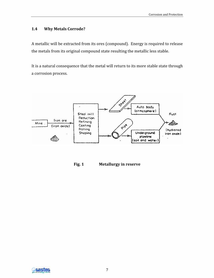
1.4 Why Metals Corrode?
A metallic will be extracted from its ores (compound). Energy is required to release
the metals from its original compound state resulting the metallic less stable.
It is a natural consequence that the metal will return to its more stable state through
a corrosion process.
Fig. 1 Metallurgy in reserve

Corrosion and Protection
8
The difficulty of extracting metals from their ores in terms of the energy required,
and the consequent tendency to release this energy by corrosion is varies from
metal to metal and is reflected by the relative positions of pure metals in
‘Electromotive series’.
Most Potassium (Active End) -2.922 (std.potential volt)
Energy Magnesium -2.34
Aluminum -1.67
Zinc -0.762
Chromium -0.710
Iron -0.440
Nickel -0.250
Hydrogen -0.000
Copper -0.345
Silver +0.800
Less Platinum (Noble or +1.200
Energy Gold Passive End) +1.680
Position of some metals in the Standard Electromotive (EMF) Series
The above standard EMF series is precisely measured between metals exposed to
solutions containing approximately one gram atomic weight of their respective ions
at a constant temperature 25°C versus hydrogen electrode. 1owever in real life
galvanic coupling between metals in equilibrium (EMF series) with their ions rarely
occurs or most engineering metals are alloys. Hence galvanic series is more practical
series to be used. It agrees closely with their constituent elements in the EMF series.

Corrosion and Protection
9
1.5 Concept of corrosion
The corrosion process is an electrochemical process by which reaction proceed by
an oxidation or (dissolution) reaction, and a reduction or (deposition) reaction. All
corrosion process involved anodic reaction and cathodic reaction. The oxidation, or
anodic reaction takes and the reduction or cathodic reaction occurs on cathodic of
the structure. The anode is at a more negative electrochemical potential and is said
be more active than the cathode. The potential difference between the anode and
cathode provides the driving force for the corrosion reaction.
Anodic and cathodic sites exist because of several factors for example:
1. Where dissimilar metals are in contact, the metal with a more
negative potential becomes the anode and that with the less negative
becomes the cathode.
2. Differential concentration, where a one metal immersed in an
electrolyte suffers due to local concentration differences e.g. salt, in
the solution.
3. Differential aeration, where a metal is immersed in an electrolyte
having a different local oxygen level. In this case, the metal end
immersed in the low oxygen content becomes the anode and that in
the high oxygen content region becomes the cathode.
4. Dissimilar temperature where metals are at different temperatures
that will create a thermo galvanic potential differences.

Corrosion and Protection
10
1.6 Corrosion process
In general all corrosion processes is an electrochemical but not every
electrochemical process is a corrosion process.
e.g : Rusting of iron
Iron + Water + Oxygen � iron Compound (Rust)
2 Fe + 2H2O + O2 � 2Fe(OH)2 (A chemical process)
At Anode / Oxidation:
2 Fe � 2Fe2+ + 4 electrons
The anodic reaction is indicated by an increase in valency, a release of electrons or
consumption of metal
At Cathode / Reduction :
2H2O + O2 + 4 electrons � 4OH-
While the cathodic reaction is shown by a decrease in valency, a consumption of
electrons or deposition of metal species.
From the above, the corrosion process involves oxidation and reduction at the
anode and cathode respectively.
Many types of anodic reactions (50 – 60% of metals) that lead to a soluble product
that promute the corrosion to continue or a solid product non-soluble that may
prevent a further corrosion process. Whereas in aqueous environment at cathode,
reduction of Oxygen is very common type as cathodic reaction compared to
evolution of Hydrogen.
Therefore, by controlling wither or both cathodic and anodic process means
controlling corrosion.

Corrosion and Protection
11
1.7 What Must a Corrosion Cell have?
Before proceed any further, it is essential to highlight the necessary conditions
which must be met before a corrosion cell can function
They are;
a) There must be an anode and a cathode
b) There must be an electrical potential between the anode and cathode. (This
potential can result from a variety of conditions on pipelines)
c) There must be a metallic path electrically connecting the anode and cathode
(Formally, this will be the pipeline itself)
d) The anode and cathode must be immersed in an electrically conductive
electrolyte which is ionized – meaning that some of the water molecules (1-
120) are broken down into positively charged hydrogen ions (&) and
negatively charged hydroxyl ions (OH-). (The usual soil moisture, or water,
surrounding pipelines normally fulfills this condition).
Once these conditions are met, an electric current will flow ad metals will be
consumed at the anode.
1.8 Effect of Current Flow on Corrosion
The amount of metal that will remove is directly proportional to the amount of
current flow. One ampere of direct current discharging into the usual soil electrolyte
can removed twenty pounds of steel in one year (i.e. approx 9kg/A.yr). This is based
on the electrochemical equivalent of the metal involved; other metals than steel will
be removed at other rates, some more and some less.
For steel, 1 ampere of current flow may only dissolve 5 micron of steel if for
example, it is uniformly over 1.0 km of 30 inch diameter pipe over 10 years period.
Corrosion and Protection
12
However, if this current is confined to an area of about 20 mm diameter of similar
pipe of 16 mm wall thickness, perforation could occur within about 4 hours.
1.9 What Damage Corrosion Caused
The corrosion damage causes many deterioration effects such as;
i) Appearance
Corrosion causes a material such as automobile turns less impressive, a
building look dull. This eventually results in the loss of economical value
of the materials
ii) Maintenance and Operation Costs
Due to corrosion, more maintenance and operation costs which will incur
into the entire operation, such as chemical plant and refinery. Better and
expensive materials may be required more work force will be necessary
and even extra tool or equipment may be needed.
iii) Plant Shutdown
Plant shutdown causes by corrosion which is usually and will always be
the most unwanted incident. Plant shutdown may directly cause less of
production and indirectly because the negative image of one’s reputation
when products or services are not delivered in time. This will be even
obvious when the plant shutdown is caused by unexpected corrosion
failures.
Regular inspection on the corrosion status of a plant, together with the
proper implementation of monitoring system are two most helpful ways
in preventing unexpected corrosion failure and plant shutdown.
Corrosion and Protection
13
iv) Contamination of Products
This effect will most costly when it evolves the products which the
market value is very much depending on their purity and quality. E.g.
Palm oil, foods, drugs, pigments, semiconductors and transparent
plastics.
v) Loss of Valuable and Dangerous Products
Oil pipeline leakage can cause environmental pollution as well as loss of
money. Furthermore, leakage of highly flammable products such as gas
can result in per critical.
vi) Effect on Safety Reliability
Corrosion on bridges and jetties can result in catastrophic failure.
Vibration together with corrosion can cause the aerospace vehicles to fail
un-expectedly. Therefore, corrosion can cause a structure to be unsafe
and unreliable.
vii) Product Liability
Corrosion may happen unexpectedly thus may not anyone’s
responsibility. Therefore, if failures are caused by corrosion, it would be
difficult in solving the liability through legal responsibility. Eventually a
party will need to spend extra fund for the unexpected damages due to
corrosion.

Corrosion and Protection
14
1.10 Environments of Corrosion
1. Atmospheric
a. Indoor - Controlled environment e.g. humidity, ambient
temperature.
b. Rural - Away from Industry, sunshine, rain, Oxygen, C02,
chemical.
c. Marine - High humidity, salts, more rain, NaCI.
Corrosion could be 300 times as severe as rural environment.
d. Industrial – Acid rain e.g. S02, HCI, Nx0x plus C02
2. Underground corrosion / soil corrosion
Soils can be considered as an aqueous electrolyte that varies widely in
physical and chemical characteristics and in their corrosivity towards
metals. They consists of a multiphase system of inorganic
components, i.e. natural rocks and minerals and also organic
components i.e. humus materials. These combinations control water
percolation rates, water retention, oxygen content, electrical
conductivity of a material is determined by several factors including
resistivity, pH, oxygen content, aggressive ion concentration and
microbial activity, the type of soil and its constituents, as the medium
on contact with a buried metal will control the corrosion.
Factors Affecting Corrosivity of the Soil
Underground corrosion in a soil is another form of corrosion and is
therefore an electrochemical process. Thus, when two points, which
are electrically connected and immersed in an electrolyte (i.e. the soil)
have a difference in potential, there will be a flow of current from the

Corrosion and Protection
15
metal termed the anode are (the most negative) through the
electrolyte (soil) to the cathode area (the most positive) then via the
metal to complete the circuit. The metal is dissolved in an anodic
reaction and species from the soil (e.g. 02) is consumed at an
equivalent rate in a cathodic reaction. The electrical current flow in
the cell is by electron transfer in the metal and ion transfer in the soil.
The electrochemical process in soils involves many complicated and
difficult factors.
Soil characteristic very variable e.g. water table, resistivity, aeration,
bacteria, soluble minerals (salts), moisture, compaction and
temperature.
3. High temperature corrosion
When a metals/alloys is oxidized at elevated temperatures greater
than about 400oC, a stable oxide or other compound generally covers
and “coats” the exposed metal surfaces. The product layer may acts a
barrier between the under laying metal and the corrosive
environment. However, in industrial practice, alloys are rarely
exposed to pure oxygen but instead environment is more variable and
complex. For example, many sources of energy and raw materials for
chemical, metallurgical and power-generation industries are
hydrocarbon fuels e.g. oil, gas, coal that containing impurities such as
S or CI hence, atmospheres can contain mixtures of O2, N2, H2, H2O, CO,
CH4, H2S, SO3, SO3, NH3, C, S2, HCI, etc. in a wide range of
concentrations and pressures. As the results, e.g. oxidation,
carburization, sulphidation, chlorination and nitridation. In addition,
molten products and / or deposits that will ca use hot corrosion

Corrosion and Protection
16
problems due presence of high concentration of Na, K, S, V-alkali
metals during combustion.
1.11 Classifications of corrosion
Corrosion can be classified in many ways. Some classifications categories corrosion
into low temperature and high temperature corrosion. However, the more general
and preferred classification is wet corrosion and dry corrosion. Wet corrosion is an
aqueous solution (i.e. electrolyte) corrosion process that occurs in the presence of a
liquid. This aqueous solution can exist either as a bulk solution, or as droplets or a
moisture layer on the metal surface. This type of corrosion is very common and the
major contributor to the corrosion problem. A common example of this type of
corrosion is steel in sea water. In contrast to wet corrosion, dry corrosion occurs in
the absence of a liquid phase or above the dew profit of the environment o a gaseous
environment. This type of corrosion is often associated with high temperature, and
is normally termed oxidation (if it occurs in a gas containing oxygen) or
sulphidation (in gas containing sulphur) or hot corrosion (if molten salts are
present).
Corrosion may classify based on the morphology of attack. Thus, localized
corrosion is associated with inhomogeneties in the metal phase or its environment,
resulting in attack on small areas or spots on the metal surface. Uniform or general
corrosion occurs more evenly over a surface and can often be permitted if its rate is
low enough so that the thickness of the metal structure is still sufficient to function
for the design lifetime. In contrast localised corrosion frequently happens with small
metal loss but with severe damage due to perforation at pits or due to cracking.

Corrosion and Protection
17
2.0 COATING
The protection of a structure can be achieved by preventing or controlling the
processes of the anodic and cathodic reactions. Application of a coating is one of the
methods that are widely used to control corrosion.
2.1 Classification of coatings
Coatings are widely used for the protection of structures. The types of coatings
mainly depend upon the method of coating, the suitability of the environment and
the type of structures to be protected. Very thin coatings are suitable for the
structures where physical and abrasion resistance is not essential whereas, the
application of very thick and tough coatings are necessary for structures where
maintenance is a problem and protection against the environment is very much
required. Therefore, the selection of a suitable material and type of coating are very
important for buried pipelines which are difficult in both maintenance and in
requirements against the soil environment.
Typical coatings for buried pipelines range from hot-applied coal tar or petroleum
asphalt-base-filled enamel, in the form of tape application i.e. Polyethylene and
polyvinyl chloride, to epoxy types that are extruded onto the pipe surface. However,
coatings inevitably have flaws and defects. Thus, to reduce this shortcoming a
combination of coating with cathodic protection is applied. Thus, the coating also
should have specific properties required for the both systems to work together due
to the chemical reactions which are taking place at both the anode and the cathode
during cathodic protection current flow.

Corrosion and Protection
18
2.2 Principle Of Corrosion Protection By Organic Coating
The coating shields the structure from the corrosive environment and cathodic
protection ensures that bare-metal defects in the coating are protected. The most
general corrosion protection mechanism is due to the barrier effect of the coating.
The efficiency of the barrier effect depends on
1. The permeability of the coating to water and water vapour.
2. The permeability of the coating to oxygen.
3. The permeability of the coating to ions.
4. The electric resistance of the coating (which is related to 3)
Absorption of water by organic, coatings is related to the concentration of water in
the electrolyte (environment). There evidence shows that, the coatings are generally
very permeable to water and oxygen. Water permeability in a coating is controlled
by the concurrent process of water absorption and diffusion. Different types of
coatings have different polymeric structural features like polymer polarity,
crystallinity, cross linkage and chain - stiffness which are very important in
determining the amount of absorbed water and diffusivity of water. The presence of
defects such as pores, holidays and fissures, will allow water to be absorbed easily
and will start corrosion on the metal underneath the coatings. The amount of water
and oxygen penetrating through a coating, even without defects, is believed to be
enough to initiate corrosion on the underlying metal.
In the case of coatings containing active pigments, the corrosion products produced
i.e. zinc oxides, hydroxides and carbonates may fill up the pores of the coating and
create a barrier to the movement of oxygen and water. In the presence of inhibitive
pigments in the coatings, the corrosion is controlled by suppressing the rate of
anodic and cathodic reaction either individually or together. Thus, a possible
parameter which may contribute to corrosion control by an organic coating is its d.c.

Corrosion and Protection
19
resistance. A high d resistance, i.e. greater than 108 Ohm-cm2, is required for a good
protective coating. Thus, even coatings without inhibitive or active pigments still
can limit corrosion by inserting a high electrical resistance component between the
anode and cathode. It is generally believed that the electrical current across
organics coatings consists of a flow of ions. Thus, the electrical resistance of coatings
is controlled by a mechanism of ionic permeation through the coatings. Also,
coatings when immersed in electrolyte will take-up a charge. Most coatings contain
the carboxyl group, which may be selectively permeable to cautions. The ions
permeate through coatings by an ion exchange mechanism. Thus, the electrical
resistance of immersed coatings may slowly change with increasing ion exchange
between the cations from the electrolyte and hydrogen ions from the carboxyl
groups in the coatings. It was shown that coatings with high ion exchange capacities
show poor corrosion protection, whereas those with low ion exchange capacities
show better corrosion protection to the underneath metal. Therefore, it can be
concluded that coatings of normal thickness are permeable to water and oxygen and
do not prevent corrosion by controlling the diffusion of these species. However,
corrosion is restricted by interposing a high electrical resistance between the
cathodic and anodic site. Thus, the electrical resistance of a coating film is controlled
by the mechanism of ionic permeation or diffusion through the films.

Corrosion and Protection
20
3.0 PAINTINGS
3.1 Introduction
The purpose of paint beside good decorative properties & colour retention is to
provide long lasting protection from corrosion resistant to chemicals and
weathering.
3.2 Principal of protection
Painting is used as one of the method employed to prevent the above ground
pipelines from corrosion. Mainly there are3 main principles methods employed:
a) Create a barrier that keeps out charged ions and retards the
penetration of water and oxygen which is called Barrier effect.
b) Ensure that water, on its passage through the paint coating, takes up
special compounds inhibiting its corrosive action that called Inhibitor
effect.
c) Ensure metallic contact between the steel and a less noble metal e.g.
zinc. This affords cathodic protection of the steel by utilizing the
Galvanic effect
3.3 Component of paints
Generally paints consist of a liquid and solid portion:
1. Binder
2. Pigment
3. Extender
4. Solvent
5. Thinner
6. Additive

Corrosion and Protection
21
4.0 CATHODIC PROTECTION
4.1 Introduction
Cathodic protection is an electrochemical method of preventing external corrosion
of buried or immersed metallic structure which in practice include pipelines, tank
bases, steel jetties, offshore platforms and ship hulls. In addition technique is used
to protect the internal surfaces of tanks and pipelines storing or transporting
corrosive liquids.
In recent years the technology of cathodically protection steel reinforcing in
concrete has been developed. However, although the principle is identical, the
application and engineering design factors are rather different.
For the purposes of this section of the course the cathodic protection of an onshore
buried pipeline is primarily considered.
In order to explain practical cathodic protection application, a brief mention is made
of coatings and other factors which effect cathodic protection design.
4.2 The Corrosion Process
Corrosion occur the surface of a metal as a result of current flowing in a corrosion
cell. The difference in potential between an anode and a cathode will cause current
to pass electronically in metal and ionical!y in surrounding electrolyle. In both
cases, electrons pass and it is in the trans of these electron across the
steel/electrolyte interface that corrosion occurs. This system can be represented in
the following simple circuit:

Corrosion and Protection
22
Figure 1 Corrosion simple circuit
Using Ohms law, the net corrosion EMF (E Ea) equals the product of the sum of the
circuit resistances and the corrosion current flowing (la). Given that the actual
corrosion process iron in its crystalline or solid elemental state converting to
soluble iron ion with the release of electrons thus:
Fe→ Fe++ + 2 electrons
Fe→ Fe(OH) +H2 + 2e
Involves the flow of electric current (the passage of electrons)- then corrosion
control processes are those which either INCREASE the resistance of the circuit or
reduce the net potential or driving voltage of the circuit: The corrosion occurring is
directly proportional to the corrosion current (lc) in the circuit.

Corrosion and Protection
23
The corrosion EMF (Ec - Fa) may be produced by bimetallic contacts, ruptured mill
scale, differential aeration, steel in concrete, bacterial action, etc. Rp, the resistance
of this metal circuit between anode and cathode is of great significance when the
anode and cathode are physically remote; long line corrosion, stray current effects
and certain differentials in the soil apply in this case. RE is the resistance of the
electrolytic circuit between anode and cathode and this is of particular importance
when anode and cathode are cIose by. The resistance of any element is related to
specific resistance by:
R = pL
A
where p = specific resistivity, A = cross sectional area and L is length When anode
and cathode are remote, A approaches infinity so that this factor may be neglected.
RAE and RCE are the resistances of the electrodes to earth and these are very easily
influences. In the instance, they are the polarisation resistances and in the second
case they may be largely a function of the soil resistivity, or of any other barrier such
as films of molecular thickness formed by a corrosion product or by artificially
produced film of high, resistance (coatings) on the pipe surface.
The severity of corrosion, then, will depend on the current flow and the anode area.
Iron goes into solution at the rate of some 9kg per ampere-year. Thus a current of 1
ampere may only remove 5 micron of steel it, for example, it is uniformly spread
over 10km of 30 inch diameter pjpe over a ten year period. If confined to an area of
about 20mm diameter of similar pipe of 16mm wall thickness, perforation could
about four hour.
4.3 Principle of Cathodic Protection
Corrosion cells develop on the same piece of metal for the various reasons and thus,
the corrosion current flows due to a potential difference between the local action

Corrosion and Protection
24
between the beat action anodes and cathodes. As the result corrosion occurs at the
ANODES which are consumed while the CATHODES remain intact. The objective of
cathodic protection is to ensure that lbs whole of the metal pipeline to be protected
is the CATHODE.
In a larger cell the anode of which is separate and renewable but using the same
electrolyte (soil). Schematic diagrams assist in understanding this concept:
Fig. 2 Schematic diagrams concept of cathodic protection
All the pipeline metal now behaves as a cathode so that the reaction of anodic
reaction cannot proceed and is replaced by the cathodic reaction.
1/202 + H20 + 2e � 2OH-
Redrawing the earlier circuit diagram

Corrosion and Protection
25
Fig.3 Application of Cathodic Protection
At this stage, it is necessary to clarify some terminalogy. The passage of electric
current is the movement of electrons. In a metallic conductor, current is regarded as
flowing in the opposite direction to the movement of electrons so that in the pipe or
cable, current flows from the cathode to anode. In soil or water, it is the movement
of ions which provide q and it is conventional to refer to ‘current’ as flowing from
anode to cathode. Thus, on a corroding pipe, current flows off the pipe at the anode
into the soil while at the cathode, current flows from the soil onto the pipe.
Cathodic protection then, depends on current flow onto the corroding surface from
the surrounding soil. It follows, therefore that the current must have a path
available from the CP anode to the metal through the same electrolyte. This that
cathodic protection cannot be applied to structures unless they are buried or
immersed. An example would be an over-ground section of a pipeline or a fitting in a
valve pit where the corroding electrolyte is merely a film on the surface of the steel.
At this stage, also, it is useful to examine the term ‘potential which will be used so
often in cathodic protection.

Corrosion and Protection
26
You will recall how we showed the electron movement with ion tending to go into
solution.
Fe � Fe2+ + 2e
This is a reaction which will always attempt to occur in solution. The pressure’ of
the reaction is measurable as a voltage which can be termed ‘solution potential’.
Like all things, standards are available to measure this and the one commonly used
because of its stability and ease of reproducibility is copper. Copper, immersed in a
solution already containing as many ions of copper (in the form of copper sulphate)
as will dissolve at normal temperatures, will always same potential.
Thus, if we wish to measure the solution potential of a metal in an unknown solution
we can couple it with the copper potential measure it and have the answer by
difference.
Metal/Electrolyte//Copper Sulphate/Copper
All that is necessary to have the copper contact the same electrolyte as the metal
while remaining in an immediate environment of copper sulphate.
This is a very useful tool since the solution potential indicates the TENDENCY (but
NOT the RATE) for the metal ion to go into solution. Let us look at a few examples:
(We will not deduct the copper potential since It will be standard throughout: the
potentials will be compared and simply ‘referred to Copper/Copper Sulphate’).
Steel in near neutral soils exhibits a solution potential of between -0.5 and -O.7
volts. When we measure this on a pipeline, we use the term pipe to soil potential.
A reactive metal such as magnesium, however, exhibits a solution potential of as
much as -1.5 volts referred to Copper Sulphate.

Corrosion and Protection
27
On an unprotected pipeline, local anodes may show a potential of -0. 8 volts while
elsewhere on the same metal surface, local cathodes may show a potential of -0.4
volts.
We have described cathodic protection as a means of converting the whole pipeline
to cathode. In order to do this, we must eliminate the differences in potential
between the local anodes and cathodes and we tend to drive all the potentials
numerically upwards (make them more negative).
It can be shown theoritically, from a consideration of the electrochemistry of that
reaction anodic reaction that when steel reaches a solution potential of 0.85 volts
referred to copper sulphate, this reaction cannot proceed, and were it reversible
would tend to go backwards. The efficiency of 0.85 volts derived theoritically as the
protective potential of steel in near neutral soils or water has also been
demonstrated experimentally. However, for this reason, and the necessity to cater
for the particular case of active sulphate reducing environment), the practical figure
of 0.95 volts is often specified. The method of measurement of pipe to soil potentials
is shown in the following diagram.

Corrosion and Protection
28
4.4 Criterion for cathodic protection
A minimum criterion for the measurement of complete protection on buried
pipelines is needed by corrosion engineer to ensure the buried pipeline is protected.
Based on practical application, several criteria have been proposed and used
particularly those in NACE standard for underground or submerged steel and cast
iron structures. These criteria are as follows:
1. In aerobic environments a potential of at least -P.850 volts as measured
between the structure and a copper-copper sulphate reference electrode
contacting electrolyte, is usually recommended. In anaerobic environments
a potential of -0.50 volts needs to be considered due to the possibility of
microbial action.
2. Adequate protection can be achieved when the structure potential shift or
‘swing’ is of at least -0.3 volts ver0us copper-copper sulphate. Determination
of this potential swing is to be made with the protective current applied. This
criteria of potential swing applies to a structure not in contact with a
dissimilar metal.
3. A minimum negative (cathodic) polarization potential of the structure shift of
100 mV versus copper-copper sulphate contacting the electrolyte. This
polarization potential shift is to be determined by interrupting the protective
current and measuring the polarization decay. When the current is initially
interrupted, an immediate potential shift will occur.

Corrosion and Protection
29
4.5 Factors to Be Considered For the Application of Cathodic Protection
4.5.1 General
Before applying cathodic protection to a metallic structure, several
factors need to be considered in order to ensure that protection can
be effective.
4.5.2 Coatings
Coatings are applied to metallic structures in order to provide
corrosion protection. Referring back to figure 1 the resistances of the
electrodes to earth RAE and RCE can be controlled by the use of
coatings, i.e. by increasing these resistances the corrosion current will
be reduced.
A coating increases the resistance of a structure to the electrolyte by
reducing the area of metal exposed. To be effective a coating must
have certain properties i.e. it must be continuous, have a high
electrical, chemical, bacterial and abrasion resistance, temperature
tolerance, good aging characteristics and must strongly adhere to the
surface of the structure.
No coating is ever perfect, there will always be gaps ‘holidays’
however by reducing the area of metal exposed to the electrolyte
the current requirement (overall current density) for cathodic
protection is reduced. If a coating is 99% effective the cathodic
protection current demand will be 1% of that required to protect the
same structure without a coating.
4.5.3 Electrical Continuity
In order to cathodically protect a structure it must be electrically
continuous to ensure the complete structure becomes cathodic. If a

Corrosion and Protection
30
structure is not continuous by virtue of it’s construction (e.g. welded),
continuity can be achieved by the use of cable bonds.
On a structure which is not electrically continuous, part of the
protection ‘current may pass through isolated sections of the
structure, in this situation current may flow out at one point and be
discharged at another causing accelerated corrosion at the discharge
point. This principle is dealt with in more detail in sect. 6.6.6(e).
4.5.4 Isolation
The design of a cathodic protection system must be based on a
defined structure, which is to be protected. This must then be
electrically isolated from any other buried or immersed metal. For
example a pipeline must be separated from other plant at each end.
Isolation is required to avoid current draining to other structures
which at best will result in a larger than necessary current demand
and at worst prevent protection being achieved at all.
It is particularly important to isolate steel structures (pipelines,
tanks etc.) from copper earth systems. Copper is electro-positive to
steel and drains cathodic protection current preferentially resulting in
very large current demands.
4.6 Practical Applications Of Cathodic Protection
4.6.1 General
Cathodic protection can be achieved in two ways by the (sacrificial)
anodes or by ‘impressed’ current. Detail of the two methods are
provided below.

Corrosion and Protection
31
4.6.2 Galvanic Anodes
Galvanic anode systems employ resolve metals as anodes connected
directly to the steel structure to be protected. The, difference in n
between the anode and the steel as indicated by their relative
positions in the electrochemical series, causes a positive current to
flow in the eIectrolyte so that the whole of the steel surface becomes a
cathode.
Three metals are commonly used as sacrificial anodes: magnesium
(principally used onshore), zinc (used both onshore and offshore) and
aluminum (used offshore).
A typical galvanic system using magnesium anodes to protect a buried
pipeline is shown in figure 5.
The link in the post may be used to measure the current flow and/or
the pipe to soil potential. In soils magnesium anodes are commonly
10-20kg in weight, about 100mm diameter by 750mm long cylinders
and provide current flow of between 10-500 mA, depending largely
on soil resistivity. Anode metal consumption is directly in proportion
to the current flowing. Magnesium for example, consumes at rate of
8Kg per ampere-y In practice, the use of sacrificial anodes is restricted
to soil resistivities less than 10000 Ohm-cm (100 Ohm-metre)

Corrosion and Protection
32
.
Fig. 5 Typical galvanic anode system
4.6.3 lmpressed current system
Impressed current cathodic protection provides the voltage necessary
to make the current to flow in the circuit by means of a D.C voltage
source and of any expendible material as the anode. AC power Es
provided to the use transformer-rectifier which produces a terminal
voltage of up to say, 48 volts. The negative pole is connected through
the link box to the structure while the positive pole passes through
very well insulated cables to inert anodes buried in soil. The anodes
are conventionally buried in coke. Coke and graphite are non metallic
in the sense that the passage of current does not dissolve them. Their
deterioration is a function of other factors so that their life, for
practical purposes, is in order of 10-20 years or more.

Corrosion and Protection
33
Fig 6 Typical Impressed Current Anode system

Corrosion and Protection
34
4.6.4 Comparison of Galvanic Anode and Impressed Current Systems
Galvanic Anodes Impressed Current
1 They are independent of any
source of electrical power
Requires a mains supply or other source of
electric power
2 Their usefulness is generally
restricted to the protection of
well-coated structures or the
provision of local protection,
because of the limited current that
is economically available.
Can be applied to a wide range of structure
including, if necessary, large uncoated
structures.
3 Their use may be impracticable
except with soils or waters with
low resistivity.
Use is less restricted to the resistivity of the
soil or water.
4 They are relatively simple to
install, additions may be made
until the desired effect is obtained.
Needs careful design although the case with
which output may be adjusted allows for
unforeseen or changing conditions to be
catered for.
5 Inspection involves testing with
portable instruments at each
anode or between adjacent pairs
of anodes.
Needs inspection at relatively few positions
instrumentation at points of supply can
generally be placed where it is easily
reached.
6 They may be required at a large
number of positions. Their life
varies with conditions so that
replacements may be required at
different intervals of time at
different parts of system.
Requires generally a small total number of
anodes.
7 They are less likely to affect any
nearby neighbouring structures
Requires the effects on other structures that
are near the groundbed of protected

Corrosion and Protection
35
because the output at any one
point is low.
structures to be assessed but interaction is
often easily corrected if necessary.
8 Their output cannot be controlled
but there is a tendency for their
current to self-adjusting because if
conditions change such that the
metal to be protected becomes
less negative, driving e.m.f. and
hence current increases. It is
possible, by selection of material,
to ensure that the metal cannot
reach a potential that is
sufficiently negative to damage
coatings.
Requires relatively simple controls and can
be made automatic to be maintain
potentials within close limits despite wide
variations of conditions. Since the e.m.f.
used is generally higher than with galvanic
anodes the possible effects of ineffective
control or incorrect adjustment for example
damage to coatings are greater.
9 Their connections are protected
cathodically.
Requires high intergrity of insulation on
connections to the positive side of the
rectifier which are in contact with soil or
water: otherwise they will be severely
corroded.
10 They cannot be misconnected
during so that polarity is reversed.
Requires the polarity to be checked
commissioning because connection, so that
polarity is reversed, can accelerate
corrosion.

Corrosion and Protection
36
5.0 Onshore Cathodic Protection-Design
5.1 Soil-Survey
a) Identification of the factors governing the corrosion process:
Clearly the principal influences will be associated with the soil in
which the structure is to be buried so that the factors associated with
the soil must be identified at an early stage. These include:
(i) Soluble Salt Content
(ii) Salt Content
(iii) Physical Nature
(iv) Acidity
(v) Organic Material Content
(vi) Water Content
(vii) Reducing Bacterial Activity
From this brief statement of the principal factors it is evident that the soil in which
the structure is to be buried is the first area to be investigated for identifying
corrosion process factors. However in the case of pipelines corrosion current may
be introduced by external factors.
Railway traction currents may short circuit’ back to the nearest sub-station through
the pipeline producing an anode at the point nearest to the sub-station, while the
same effect can be produced by adjacent cathodic protection systems in certain
circumstances.
Buried pipelines may also be effected by currents induced from out of balance
overhead electricity distribution systems, which could cause anodic areas and in
very long pipelines, geo-physical currents have been measured.

Corrosion and Protection
37
In the case of steel, the commonest corrosion initiator of all is the corrosion
potential set up by the difference between steel bearing intact millscale and steel
with the millscale film disrupted.
b) Investigation in Practice
In the case of a proposed pipeline, the soil and other relevant conditions along the
route should be investigated. A record of the principal factors described above
should be made: representative soil resistivities and soil analysis should be carried
out and obvious hazardous areas such as sea water inlets, peaty areas, tips, effluent
discharge points, polluted land or water, areas containing carbonaceous waste
(cinders), electrified railway crossings, parallelisms with overhead high voltage
distribution schemes and other cathodic protection systems identified.
When using soil resistivity to indicate the probable corrosive effect of soils to bare
steel or iron it is understood that corrosivity will also vary with soluble salts and
water contents of the soils, however, a general correlation between soil resistivity
and the aggressiveness of the soil, ignoring other factors, can be broadly made as
follows:
Soil Resistivity Nature of Soil
Less than 1000 ohm-cm Highly aggressive
1,000 - 3000 ohm-cm Aggressive
3,000- 10,000 ohm-cm Mildly aggressive
Over 101000 ohm-cm Unlikely to be aggressive
In general, soil types encountered can be classified as follows:
Sea water/salt sands Less than 100 ohm-cm
Coastal soils 100-3,000 ohm-cm
Clays 1,000-3,000 ohm-cm
Sandstones and shales Up to 30,000 ohm-cm

Corrosion and Protection
38
Coarse gravel, fine Up to 100,000 ohm-cm
Sand and rock and over
Noting however that these general resistivity values can be greatly reduced by local
intrusions of salt water or industrial or agricultural pollution.
This information should also be obtained in the case of existing pipelines. However,
for these, additional data on linear electrical continuity, resistance to earth and
construction techniques should be sought. Direct measurement of coating quality,
cathodic protection current requirement and remaining wall thickness is possible,
and trial pits will provide visual corroboration of these findings.
5.2 Current Density
NACE quote the following information for the cathodic protection of steel in
soil:
Uncoated Steel � 10 – 30 mA/m2
Poorly coated Steel � 1 mA/m2
Well coated Steel � 0. 03 mA/m2
Very well coated Steel � 0.003 mA/m2
The variation between 10 mA/m2 and 30 mA/m2 for bare steel in soil is
dependant on the soil resjstivity with the lower figure being applicable in
higher soil resistivities with an increase up to 30 mA/m2 with decreasing
resistivity.
5.3 Determination of Cathodic Protection System Type
Having obtained information on the soil in which the structure is to be
buried, the structure itself must be analysed.

Corrosion and Protection
39
The primary parameter is the surface area to be protected. This must be
assessed in conjunction with the applied coating system. Generally as stated
in Section 6.5.4 galvanic anode system as applicable protecting small, well
coated structures such as short pipelines and for the provision of local
protection on larger structures.
Impressed current systems are normally utilized on larger structures where
current demand will be significant.
It is common practice on long pipelines to provide temporary protection by
means of galvanic anodes in low resistivity areas during the construction
phase and until the permanent impressed current system is installed and
commissioned. This is typically several months after the completion of pipe
laying.
5.4 Galvanic Anode System Design
Having calculated the current requirement from the surface area, coating
quality, soil resistivity, parameters anode type, weight and location must be
determined for protection over the required life.
Except in very low soil resistivities, magnesium is the only practical material
to use for the protection of buried structures.
Anode weight can be calculated from the following equation:
Wt (kg) = Current (Amosi x 8766 x Life (Years
Capacity (Amp Hrs/Kg) x Utilization Factor
Where
i) Capacity is the current available per unit weight of the material. For
magnesium the theoretical capacity is 2200 Amp Hours per Kg,

Corrosion and Protection
40
however as the material has an efficiency of 50%, a value of 1100 Amp
Hrs/Kg must be used for practical purposes.
ii) Utilization Factor relates to the point where the anode Is consumed
such that the remaining material is insufficient to provide the
required current output. For magnesium in soil this point is reached
at 85% consumed ie. the utilization factor is 0.85.
Magnesium anodes are available in standard sizes so when the
required weight has been calculated the size and number of anodes
can be decided. Depending on the structure, and soil parameters it
may be best to use a small number of large anodes or mare smaller
anodes.
Individual anode outputs can be determined from anode resistance Ra
formula, the most commonly used for onshore anodes is the
Dwight I modified formula.
Ra = P (In 4L - 1)
2 Π L r
Where:
P - Soil resistivity (Ohm-cm)
r - Anode radius (in cm)
L - Anode length (in cm)
R2 - Anode resistance
From this formula the anode current is calculated from:
1a = Vd/Rd
Where:
Vd - Driving Voltage (volts)
I a - Current (Amps)

Corrosion and Protection
41
The current obtainable from the anode(s) should then be cross checked
against the total current requirement.
5.5 Impressed Current-Cathodic Protection System Design
a) Introduction
Several factors need to be considered when locating and designing
onshore impressed current cathodic protection groundbeds in order
to provide satisfactory long term protection to buried structures.
b) Groundbed Location
The single most important factor for groundbed location low soil
resistivity site will enable a low resistance groundbed to be
constructed with a minimum of material and installation costs.
On long pipelines the maximum separation between groundbeds is
dictated by the current spread available from a groundbed site which
is determined by pipeline resistance, coating condition and potential
requirements, see section below.
d) However, working within the maximum spread normally allows a
significant distance along the pipe route to be considered for
groundbed location.
On fixed structures such as piling, tank bottoms etc there may be very
little flexibility in groundbed location, however, soil resistivity can
vary over short distances.
Other factors to be considered are as follows:

Corrosion and Protection
42
e) Power Supply
Available AC power supply will enable a transformer- rectifier to be
used. In remote areas alternative power sources can be used such as
solar power, or generators but these options are a great deal more
expensive than using an AC supply and if possible groundbeds should
be sited to make use of it.
d) Remoteness
Groundbeds should be at least 100m away from 1.he.s which is to be
protected and as far as possible (minimum 300mjjrom other buried
metallic structures. It is most important that a foreign service does
not short circuit the groundbed i.e. pass close to it and then to the
protected structure.
e) Ease Of Construction
Consideration should be given to access and operating space for plant
and equipment.
f) Land Acquisition
On pipeline routes, remote groundbeds are inevitably off the right of
way, requiring additional land purchase, where possible sites should
be chosen to avoid difficulties in land acquisition. In plant areas,
groundbeds should preferably be sited within existing boundaries.
g) Groundbed Type
There are several types of basic groundbed design.
i) Standard Horizontal
This is the simplest type of groundbed consisting of inert
anodes laid horizontally at intervals in a trench filled with

Corrosion and Protection
43
carbonaceous backfill. This design is suitable when surface
ground conditions are reasonably dry (i.e. a trench up to 2
metres deep can be opened and kept clear of water) and
surface soil resistivities are low.
ii) Vertical Anode
This type of groundbed consists of inert anodes installed
vertically at intervals in small boreholes and surrounded with
carbonaceous backfill.
This design is utilized when surface resistivities are high with a
lower resistivity directly below (5- 10 m depth).
iii) Borehole
Deep borehole groundbeds are used when surface resistivities are
high with low resistivity existing only at length. Anodes are installed
in the low resistivity zone surrounded by carbonaceous backfill.
Typically boreholes are 50- 100 m deep.
Borehole groundbeds are also used where surface space is at a
premium such as in plant areas. Remoteness being achieved vertically
rather than horizontally.
iv) Canistered Anode Groundbeds
As stated above, anodes are normally surrounded with a
carbonaceous backfill material. In very wet-swampy conditions,
installing carbonaceous backfill can be difficult and there is always a
risk of wash out before consolidation can occur. The use of anodes
prepackaged with a backfill in a sheet steel canister overcomes this
problem. Installation is very easy and the steel canister will corrode
away leaving anode in backfill after consolidation has occurred.
Canistered anodes can be installed either horizontally or vertically.

Corrosion and Protection
44
v) Anode Type
Silicon Iron, graphite and magnetite materials are all commonly used
in buried onshore groundbeds and generally exhibit similar
properties when surrounded with carbonaceous backfill.
The recently developed mixed metal oxide tubular anodes also
perform well in carbonaceous backfill and are particularly applicable
for borehole groundbeds as installation is much easier than with
other types of anode.
vi) Carbonaceous Backfill
In the vast majority of onshore groundbeds, a carbonaceous backfill
material is used to surround the inert impressed current anodes.
The backfill increases the effective size of the anode obtaining a lower
resistance to earth, and by forming the anode/soil interface carries
the majority of the consumption resulting from current discharge.
h) Groundbed Design
Deciding groundbed size, plus the number, size and spacing of anodes in a
groundbed depends on several factors primarily:
i. Required groundbed resistance to earth
ii. Required current capacity
iii. Maximum anode current density
iv. Anode weight (based on consumption)
The groundbed design therefore needs to meet the worst case of any of these,
which often means other factors are exceeded by significant amounts. The
recommended method having chosen the basic groundbed type is to size the
groundbed according to the desired maximum resistance and then to cross

Corrosion and Protection
45
check that sufficient anode material is available to provide the required
current and allowing for anode consumption.
Groundbed Resistance
The groundbed resistance to earth is primarily determined by the soil
resistivity in which it is installed. It is the normally the largest factor in the
overall circuit resistance which also includes cable resistance, the resistance
across the structure coating and the resistance required to overcome the
Back EME the groundbed and structure (of the order of 2 volts for most
anode materials).
The cable and coating resistance components can be calculated accurately
but a rule of thumb is to allow 0.5 ohms for all the additional factors.
The groundbed resistance to earth is calculated using an appropriate formula
for the geometry of the proposed installation.
Anode Current Density
As a general guide, the required anode surface area approximately 50% of
the quoted maximum current density.
Once sized, the minimum number of anodes can then be determined by
dividing in the total current requirement by. the current obtainable from one
anode.
If the anode material maximum current density is quoted at A/m2 using an
anode with a surface area of 0.5 m2, at 15 Nm2 the current output would be
7.5 Amps. Therefore if a total of 30 Amps was required a minimum of 4
Anodes would be needed.

Corrosion and Protection
46
Anode Weight
The minimum total anode weight required can be calculated from:
Wt (kg) = current (Amps) x Life (Yrs) x Consumption (Kg/Amp –Yr)
Utilization Factor
Example:
Current = 30 Amps
Required Life = 20 Years
Consumption = 0.1 Kg/Amp-Yr
Utilization Factor = 0.5(50 %)
Wt(kg) = 30x30x0.1 120kg
0.5
Therefore, if 20 kg anodes are used a minimum of 6 nos. are required.
Spread
When installed and commissioned if we plot the pipe to soil potential before and
after the application of cathodic protection to a pipeline from a single power
impressed cathodic protection station, typical results are demonstrated below:

Corrosion and Protection
47
Figure 7 Pipe to soil potential before and after the application of cathodic
The well coated line is protected over the full 40 kilometres using a current of 10
amperes (at say 10 volts) and with a peak potential of -1.05 volts. Practically this
could represent a current density requirement in the order of 25 micro amperes per
square metre of coated pipe. The poorly coated, or bare me, requires the drain point
potential to be elevated to -1.8 volts for a protective spread of less than 16
kilometres; a current of 100 amps is utilised with current density in the order of 1 to
3 milliamps per square metre of pipe.
The extent to which current will spread from a single installation is a function of:
• limits to which the drainage point potential can be depressed
• soil resistivity
• coating quality
• pipeline continuity resistance

Corrosion and Protection
48
It is also affected by intrusive factors such as the connection to the line of a bare
metal area, ‘interaction’ from DC to AC services or localised loss of coating or
continuity.
The ultimate cathodic reaction is the production of alkali and hydrogen. Alkaline
materials are protective to steel but hydrogen is thought to cause inter-crystalline
embrittlement and fracture. Hydrogen does not normally evolve before the pipe/soil
potential is more negative than -2.5 volts but this is almost entirety dependant on
the surface condition of the steel and soil conditions. In any case, the evolution of
volumes of hydrogen or the production of alkali is disruptive to any coating material
and for this reason the limiting pipe/soil potential at the ‘drain’ point is generally
taken to be -2.5 volts.
Soil resistivity as a rough measure of soil aggressivity also dictates the level of
current density necessary to provide protective potential. This is likely to be very
much greater in low resistivity soils/aerated salt marshes or anaerobic clays than in
high resistivity areas. The greater the current demand, the greater is the current
flow in the pipeline itself. Measured current flow in the pipeline results in increased
‘volt drop’ along the pipeline so that it becomes necessary to produce a high drain
point potential in order to achieve the required minimum at the distant point. This
current spread is dependent on current demand which is function of coating quality
and pipeline linear resistance.
These factors are susceptible to a mathematical evaluation and by combining this
theoretical approach with practical parameters, it becomes possible to specify
coating quality by stipulating the current density necessary to achieve a given
distant change in potential with a specified maximum change in potential at the
drainage point.

Corrosion and Protection
49
5.6 Special Considerations for Onshore Cathodic Protection
a) Sparking Hazards
Where impressed current cathodic protection systems are used in
plant areas for the control of corrosion of buried pipelines and buried
metallic storage vessels both the buried and the above ground pipe
work becomes part of the cathodic protection electrical circuit. When
it becomes necessary to break the electrical continuity of these
circuits (e.g., through the separation of pipe work from vessels or the
removal of pipe work spool pieces! valves, or cold cutting of pipe
work) there is a risk that if a flammable gas or vapour environment
exists, incentive sparking may occur as the circuit is broken or when
the circuit is purposely or accidentally remade and a fire explosion
could result. Generally, the system of inter-bonding between
catholically protected product pipelines, fire mains and copper
earthing creates parallel paths for cathodic protection current. These
paths may act to prevent sparking when p is broken but cannot safely
be relied upon as they cannot be readily identified. It must therefore
be considered necessary to have a system whereby electrical
continuity is not disturbed during the removal of pipe sections or
equipment in hazardous areas or on product carrying pipelines and
this may be achieved by the use of safety bonds.
b) Earth Electrodes
Where cathodic protection is applied to plant area buried structures
and their associated earth electrodes, it is possible that the protection
system may cause a reduction in the efficiency of these earth
electrodes.
This possible increase in earth resistance, results from a high
resistance coating being formed on the copper electrode. Periodic

Corrosion and Protection
50
maintenance should be undertaken to check, in particular, the
resistance of earth electrodes located close to impressed current
groundbeds.
c) Sleeved Crossings
The environment inside a sleeve is very different to the environment
of a conventionally buried pipeline. If designed to be air the possibility
always exists that soil water will fill the annulus. The danger is that a
differential condition is established and supplementary cathodic
protection in the form of galvanic anode ribbon should be allowed for
within the annulus.
Other approaches have been to design to produce a specific condition
susceptible to corrosion prevention. Small diameter lines can be
sleeved in pipe of larger diameter with inert gas in the space in which
case the external sleeve surface is treated as the rest of the pipeline.
Alternatively, and in the case of larger lines, both the carrier pipe and
sleeve should be well coated and insulated from each other and
provision made for the annular surface to be well drained or filled
with a gel of conducting material so that the carrier pipe may be
cathodically protected.
d) Valve Pits
As with sleeved crossings, conditions inside a valve pit will differ from
the rest of the pipeline. Pits designed to be drained do nevertheless fill
with water, or at best provide a very high humidity climate in which
corrosion is rapid in the vapour phase. In these cases, corrosion
prevention should be based on the use of coatings and local cathodic
protection by galvanic anodes which would automatically energize
when the water level reached pipe invert.

Corrosion and Protection
51
e) Cathodic Protection Interaction
Whenever there is current flow in the earth, from whatever source, a
piece of metal buried in the earth may function as a part of the current
path, collecting current over a part of its surface and discharging it
with attendant corrosion from another pad.
This may be illustrated by a ‘secondary’ structure or pipeline passing
within the influence of a cathodic protection system installed on the
primary structure. Here current from the groundbed may utilise the
secondary structure to return to the cathodic protection power
source, most likely discharging from the secondary structure at its
crossing point with the primary protected structure.
This condition is recognised by pipe to soil potential changes at point
on the secondary structure when the protection system the crossing is
energized. Changes in potential which tend to produce an anodic
condition must be dealt with and this can be done b the two pipe lines
together. This effect is illustrated by the figure 8.
Fig.8 Interaction at pipe crossing

Corrosion and Protection
52
f) AC Induced Effects
Pipelines buried parallel to high voltage overhead transmission lines are
subject to induced alternating voltages from the currents flowing in the
powerline cables. The pipeline voltages are produced by the electric field
transformer coupling between the three-phase current- carrying overhead
conductors and the buried metal pipe which is normally isolated from the
surrounding earth by the electrically insulating anti-corrosion coating. Under
balanced (equal) current flow in each phase of the powerlines, the induced
voltage in the pipeline is normally less than 10 volts as the sum of the field
effects of the load currents is small and results only from different distances
between the pipeline and each conductor.
However, the induced pipeline voltage will increase markedly during AC
transmission line faults which may be caused in a variety of ways. Typically,
faults may because by the earthing of any of the conductors, unbalanced
loading of three phases or by lightning strikes. Any of these faults may cause
large 3 currents to flow in the conductors, which will produce strong
alternating electric fields to couple with buried pipeline and induced high
voltages over the parallelism.
The magnitude of the induced voltage will depend on several transmission
line and pipeline factors. For example, the distance separating the power line
and pipeline, the distance over which they are parallel, the existence of other
parallel pipelines, the pipeline coating quality, pipeline earths, the effect of
the powerline earth conductor and the trip time of the powerline protection
devices. The voltage gradient produced over the pipeline rises at the ends of
the parallelism as would be expected of an open circuit conductor in
alternating electric field. The value to which the voltage rises will be affected
in several ways. The AC powerline earth conductor will cause the electric
field to be reduced because the currents induced in the earth conductor will

Corrosion and Protection
53
flow in opposition to the fault current and produce an electric field which is
also in opposition to the field of the fault current. The resulting total field
strength affecting the pipeline is therefore weakened. Multiple pipeline
routes will be less affected by induced voltages than single pipeline
parallelisms. The paralleling pipes will share the induced, energy with
resulting lower voltages per pipeline and, by virtue of the larger surface area,
increased leakage. A similar reduction in level will occur from fault currents
flowing through the earth from the pylon footings when the conductor is in
fault contact with the powerline. Operators working on valves or cathodic
protection equipment or passers-by touching exposed cathodic protection
cables are most vulnerable to these voltages and efforts need to be made to
reduce the voltages to levels such that safety is assured and equipment is not
damaged. The most effective method of reducing the voltage is to change the
condition of the pipeline from an open ended, insulated conductor to one
forming part of a current carrying close circuit.
This condition is most easily produced by connecting the pipeline to the
surrounding soil, enabling current to flow through the soil along the voltage
gradients occurring along the pipeline from the induced voltage effect. In one
case, zinc earth electrodes were installed at the ends of each parallelism with
additional electrodes placed at 4 km intervals along the route. The electrodes
‘connect’ the pipe to the soil and by allowing a flow of current, the voltage
rise is limited. The resistance to earth of the electrodes is kept below 7 ohm
so that the volt drop at the electrode due to current flow and the resistance
does not rise to dangerous levels.
In addition, where operators were required to work on pipeline equipment
such as line valves, earth mats of zinc ribbon were laid round the valve and
connected to the pipeline. An operator standing by a valve and in contact
with it, would not therefore be at risk should a high voltage be induced on the
pipeline since the earth mat potential and the surrounding soil on which the

Corrosion and Protection
54
operator stands would change voltage with the pipeline, preventing the
operator becoming an earth path. The potential between the equipment
being touched and the operators foot or the space between this feet when
walking is referred to as the is ‘step voltage and to be safe, should not exceed
200 volts for a fault duration of 200 microseconds.
All surface fittings and other test facilities on the pipeline along the
parallelism are out of the public’s reach and cathodic protection test
terminals, normally exposed at test posts, are enclosed in posts made of high
impact non-conducting materials.
A further effect of induced AC voltages is that by being conducted to earth
through a cathodic protection station, AC is converted to dc and in effect
becomes an impressed current power source. This effect may not be totally
beneficial as pipe to soil potentials from this source may easily exceed the
designed limits.
The flaw of AC through the cathodic protection station may, however be
limited by the use of inductive and capacitive circuits which will by pass the
current around the transformer - rectifier. The typical circuit is shown in the
following Figure 9.
6.0 Cathodic Protection Equipments and Maintenance
6.1 General
Although materials and equipment has been discussed in various
parts of the course a brief survey of the most important materials is
provided and typical manufacturers data sheets.

Corrosion and Protection
55
6.2 Transformer-rectifiers
A transformer-rectifier steps down the mains AC supply voltage
(230V single or 41 5V 3-phase) to a low AC voltage (25/50 volts) and
then rectifies via a full wave bridge connected circuit, the low voltage
to direct current. The transformer is provided with switched
transformer taps which vary the AC transformer output, an ammeter
and voltmeter and protective circuits and fuses. As the unit operates
continuously, large units are oil cooled. Small units may be air cooled
in temperate areas. Alternative DC supply sources are solar
generators, thermo electric generators, closed cycle vapour turbines,
diesel and gas generators.
6.3 Sacrificial Anodes
These are castings of various weights of magnesium, zinc or
aluminum alloys round a steel core. For land use magnesium is used
and a cable is attached to the core. Zinc and aluminum are generally
used for marine service when the cores are welded to the structure
being protected.
6.4 Impressed Current Anodes
These are castings of silicon iron of various weights into which cables
are connected by lead run joints. Alternative anode materials are
graphite, magnetite and, in marine use, platinised titanium and
niobium.
6.5 Backfill
To reduce the resistance to earth of buried anodes, they are often
buried in trenches or pits filled with coke, calcined refinery coke or
graphite. Burial in coke increases the life of the anodes.

Corrosion and Protection
56
6.6 Insulated Flange and Isolating Joints
Electrical isolation may be achieved by the use of either insulated
flanges or monolithic isolating joints. Isolating joints are considered to
possess a far higher degree of electrical and mechanical reliability
then insulated flanges, as isolating joints may be factory assembled
and tested to the client’s requirements, whereas insulating flanges
rely on the site installation of insulating materials into standard
flanged assemblies.
7.0 Specialised Pipeline Survey
7.1 General
A number of specialised pipeline surveys which provide detailed
monitoring of the pipeline cathodic protection and/or external
coating system are available. In addition to the traditional Pearson-
type coating survey, two further surveys may now be considered the
close-interval potential survey (CIPS) and the signal attenuation
coating survey (SACS). Each survey has its particular applications and
indeed, the surveys may be used in conjunction with each other.
7.2 Close-Interval Potential Survey (CIPS)
The usual cathodic protection operating procedure is to monitor the
performance of the system and by interference, the performance of
the external coating system, on a pipe to soil potential measurement
sampling basis. Under normal circumstances these measurements
provide an acceptable indication as to the overall protection level on
the pipeline.
The measurement of potentials at say I km intervals is, however, only
valid where coating quality is predictable, thus ensuring consistent
cathodic protection levels. If this is not the case, then it cannot be

Corrosion and Protection
57
assumed that potentials are maintained between test posts and an
intermediate defect may remain undetected.
Where variable coating or environmental variations are suspected,
pipe to soil potential surveys may be completed at close intervals
along the pipeline, in order to locate any inadequacies in the corrosion
protection system. Such a close-interval potential survey may be
undertaken at any selected measurement interval, relating to the
variations in coating quality, the diameter and the depths of the
pipeline. Typical values are between I and 5 meters.
The survey method may also incorporate the measurement of
instantaneous ‘OFF’ potentials where syncronised interrupter units
are installed at the cathodic protection stations to interrupt the dc
supply for short cyclic periods. Commonly this cycle time is I second
‘OFF’ and between 2 and 4 seconds ‘ON’, depending on the
polarisation characteristics of the pipeline. Time synchronisation of
the interrupters is confirmed at the beginning and end of each
working day.
The value of recording an instantaneous ‘OFF potential is that it
provides a record of a polarised potential which is ‘IR drop’ free. In
addition the comparison of ‘OFF’ and ‘ON’ potentials will provide
valuable information on the pipeline coating quality and the remedial
works subsequently required.
To deal with the large volume of information gathered during a close-
interval potential survey, purpose built voltmeter/programmable
data loggers and Computer software is required.

Corrosion and Protection
58
7.3 Signal Attenuation Coating Survey (SACS)
When it is required to provide an overall evaluation of a pipeline coating
system without walking the entire pipeline route, a signal attenuation
coating survey will provide an economic and effective method.
Such a survey utilises a 1000 or 8000 Hz alternating current signal connected
between the buried pipeline and a remote earth. The alternating current
electromagnetic field may be measured above ground and this enables the
level of current flow in the pipeline to be ascertained.
The alternating current flowing in the pipeline is thus recorded by this means
using a calibrated, tuned pick-up coil and signal conditioning system. The
voltage induced in the coil is proportional to the current in the pipe but is
varied by pipe depth. The pipe depth is accurately measured at each signal
measurement point and the receiver signal calibrated to allow for signal loss
related to the depth measured.
Utilising such an instrument, current readings may be recorded at discrete
points on the pipeline and the data rapidly analysed to reveal the signal
current loss over any section of pipe. It is possible therefore to use this
technique to monitor, normally inaccessible sections, i.e. river, rail and road
crossings, by recording a current reading each side of the crossing.
A typical procedure for a signal attenuation coating survey would be to
record current at intervals which produce signal losses of about 4 dB. If a
pipeline section is seen to be losing significantly more than the expected loss,
the fault location may be found, firstly, by taking readings at subsequent half-
way points and finally by walking the pipeline and constantly monitoring the
current level.

Corrosion and Protection
59
7.4 Pearson -Type Coating Survey
The information gained from this survey, is subjective and is particularly
reliant on the experience of the survey operator.
Where access along the pipeline is freely available the Pearson-type coating
survey may still be economically employed; particularly on a newly laid
pipeline where coating defects are likely to be isolated. Classification of
defects, however, may only be confirmed by selected excavation and
inspection.
7.5 Direct Current Voltage Gradient (DCVG) survey
When dc current is applied to a pipeline in the same manner as in cathodic
protection, ground voltage gradients are established due to the passage of
current through the resistive soil. A well coated pipeline has a high resistance
to the soil. However, at defects the resistance is lowered such that current
flows through the soil. The flow of this current will create a voltage gradient
which becomes steeper as it approaches to a defect. The larger the defect size
the greater the current flow and hence voltage gradient.
An asymmetrical dc signal impressed onto the pipeline is switched ON and
OFF in the ration of 3:1 per second. A sensitive millivoltmeter is used to
measure the out of balance signal between two half cells placed in the voltage
gradient at the vicinity of the defect. The direction of deflection will
represent the direction of current flow due to the voltage gradient. The
defect location can be determined by tracing up and down in parallel or
perpendicular direction to the pipeline. As a defect is approached, the
operator will see the milivoltmeter start to respond to the impressed dc
signal and point in the direction of current flow. When the defect is passed,
the deflection will reverse and slowly diminish as it moves away from the
defect. By tracing the defect to where the half cells show a null deflection on
the meter, it is then located midway between the two half cells.

Corrosion and Protection
60
8.0 Conclusion
The content of this course is intended to provide overview of cathodic
protection.
Although some formulae and design parameters are stated document must
not be considered as a design guide. It vital in designing any cathodic
protection system that qualified, experienced cathodic protection engineer
consulted.
9.0 References and Suggested Additional
i) British Standard Code of Protection.CP7631:1991
ii) Cathodic Protection by John Morgan
iii) Control of Pipeline Corrosion by A.W Peabody