cornice di mandata e d aspirazione delivery and intake
TRANSCRIPT

MANUALE D’USO E INSTALLAZIONEUSE AND INSTALLATION MANUALM A N U E L D ' U T I L I S A T I O N E T D ' I N S T A L L A T I O NB E D I E N U N G S - U N D I N S T A L L A T I O N S A N L E I T U N GMANUAL DE USO E INSTALACIÓN
CORNICE DI MANDATA E D’ASPIRAZIONEDELIVERY AND INTAKE FRAME GRILLE DE SOUFFLAGE ET D'ASPIRATION AUSBLAS- UND ANSAUGGITTER INVERTERPLAFON DE ENVÍO Y DE ASPIRACIÓN
AGLL10/20NFJ 1107_4528571_00
GLL10NGLL20N

OSSERVAZIONI
REMARKS
REMARQUES
OBSERVACIONES
Conservare i manuali in luogo asciutto, per evitare il deterio-ramento, per almeno 10 anni per eventuali riferimenti futuri.Leggere attentamente e completamente tutte le informa-zioni contenute in questo manuale. Prestare particolarmen-te attenzione alle norme d’uso accompagnate dalle scritte “PERICOLO” o “ATTENZIONE” in quanto, se non osservate, possono causare danno alla macchina e/o a persone e cose.Per anomalie non contemplate da questo manuale, interpellare tempestivamente il Servizio Assistenza di zona.L'apparecchio deve essere installato in maniera tale da rendere possibili operazioni di manutenzione e/o ripara-zione.
La garanzia dell'apparecchio non copre in ogni caso i costi dovuti ad autoscale, ponteggi o altri sistemi di elevazione che si rendesero necessari per effettuare gli interventi in garanzia.AERMEC S.p.A. declina ogni responsabilità per qualsiasi danno dovuto ad un uso improprio della macchina, ad una lettura parziale o superficiale delle informazioni contenute in questo manuale.Alcune immagini potrebbero illustrare particolari forniti come accessori a pagamento.Il numero di pagine di questo manuale è:
Store the manuals in a dry location to avoid deterioration, as they must be kept for at least 10 years for any future reference.All the information in this manual must be carefully read and understood. Pay particular attention to the operating stan-dards with “DANGER” or “WARNING” signals as failure to comply with them can cause damage to the machine and/or persons or objects.If any malfunctions are not included in this manual, contact the local After-sales Service immediately.
The apparatus must be installed in such a way that maintenan-ce and/or repair operations are possible.The apparatus's warranty does not in any case cover costs due to automatic ladders, scaffolding or other lifting systems neces-sary for carrying out repairs under guarantee.AERMEC S.p.A. declines all responsibility for any damage whatsoever caused by improper use of the machine, and a par-tial or superficial acquaintance with the information contained in this manual.The number of pages in this manual is :
Conserver les manuels dans un endroit sec, afin d’éviter leur détérioration, pendant au moins 10 ans, pour toutes éventuelles consultations futures.Lire attentivement et entièrement toutes les informations con-tenues dans ce manuel. Prêter une attention particulière aux normes d’utilisation signalées par les inscriptions “DANGER” ou “ATTENTION”, car leur non observance pourrait causer un dommage à l’appareil et/ou aux personnes et objets.Pour toute anomalie non mentionnée dans ce manuel, contac-ter aussitôt le service après-vente de votre secteur.
Lors de l'installation de l'appareil, il faut prévoir l'espace nécessaire pour les opérations d'entretien et/ou de réparation.La garantie de l'appareil ne couvre pas les coûts dérivant de l'utilisation de voitures avec échelle mécanique, d'échafauda-ges ou d'autres systèmes de levée employés pour effectuer des interventions en garantie.AERMEC S.p.A. décline toute responsabilité pour tout domma-ge dû à une utilisation impropre de l’appareil et à une lecture partielle ou superficielle des informations contenues dans ce manuel.Ce manuel se compose de pages:
Guarde los manuales en un lugar seco para evitar su deterioro, al menos durante 10 años, por si fuera posible consultarlos en el futuro.Leer atenta y completamente todas las informaciones con-tenidas en este manual. Preste particular atención a las nor-mas de uso acompañadas de las indicaciones “PELIGRO” o “ATENCIÓN” puesto que, si no se cumplen, pueden causar el deterioro de la máquina y/o daños personales y materiales.En caso de anomalías no contempladas en este manual, con-tacte inmediatamente con el Servicio de Asistencia de su zona.El aparato debe ser instalado de manera que haga posibles las
operaciones de mantenimiento y/o reparación.En cualquier caso, la garantía del aparato no cubre los costes derivados del uso de escaleras automáticas, andamios u otros sistemas de elevación necesarios para efectuar las intervencio-nes en garantía.AERMEC S.p.A. declina cualquier responsabilidad por cual-quier daño debido a un uso impropio de la máquina, o bien a una lectura parcial o superficial de las informaciones conteni-das en este manual.Número de páginas de este manual:
B e wa h r e n S i e d i e G e b ra u ch s a n l e i t u n g e n m i n -d e s t e n s 1 0 J a h r e f ü r e v e n t u e l l e s z u k ü n f t i -ges Nachschlagen an e inem t rockenen Or t au f .Alle in diesem Handbuch enthaltenen Informationen auf-merksam und vollständig lesen. Insbesondere auf die Benutzungsanweisungen mit den Hinweisen "VORSICHT" oder "ACHTUNG" achten, da deren Nichtbeachtung Schäden am Gerät bzw. Sach- und Personenschäden zur Folge haben kann.Bei Betriebsstörungen, die in dieser Gebrauchsanweisung nicht aufgeführt sind, wenden Sie sich umgehend an die zuständige Kundendienststelle.
Das Gerät so aufstellen, dass Instandhaltungs- und/oder Reparaturarbeiten durchgeführt werden können.Die Garantie des Gerätes deckt in keinem Fall Kosten für Feuerwehrleitern, Gerüste oder andere Hebesysteme ab, die sich für die Garantiearbeiten als erforderlich erweisen sollten.Die AERMEC S.p.A. übernimmt keine Haftung für Schäden aus dem unsachgemäßen Gebrauch des Gerätes und der teilweisen oder oberflächlichen Lektüre der in diesem Handbuch enthalte-nen Informationen.Die Seitenanzahl diese Handbuches ist: Nr. Seiten
HINWEISE

3
Ital
iano
AGLL10/20NFJ 1107_4528571_00
GLLI10NGLLI20N
Bevilacqua, 15/11/2011 La Direzione Commerciale – Sales and Marketing Director Luigi Zucchi
AERMEC S.p.A.I-37040 Bevilacqua (VR) Italia – Via Roma, 996Tel. (+39) 0442 633111Telefax (+39) 0442 93730 – (+39) 0442 93566www .aermec. com - info @aermec. com
Le présent produit doit être installé, exclusivement, associé avec les unités FCL de notre production.La certification suivante est valable uniquement si ces associations sont respectées:
CERTIFICAT DE CONFORMITÉ Nous soussignés déclarons sous notre exclusive responsabilité que le produit:ACCESSOIRES série GLL_Nauquel cette déclaration fait référence, est conforme aux normes harmonisées suivantes:
Dieses Produkt darf ausschließlich in Verbindung mit den von AERMEC hergestellten FCL -Inheiten installiert werden. Nachstehende Bescheinigung ist nur dann gültig, wenn folgende kombinationen vor-kommen:
KONFORMITÄTSERKLÄRUNG Wir, die hier Unterzeichnenden, erklären auf unsere ausschließlich Verantwortung, dass das Produkt:ZUBEHÖR der Serie GLL_N
auf das sich diese Erklärung bezieht, den folgenden harmonisierten Normen entspricht:
al que esta declaración se refi ere, está en conformidad a las siguientes normas armonizadas:- Directiva de Baja de Tensión: LVD 2006/95/CE- Directiva Compatibilidad Clectromagnétic: EMC 2004/108/CE con accesorios no suministrados por Aermec.
- CEI EN 60335-2-40
- CEI EN 55014-1- CEI EN 55014-2
- CEI EN 61000-6-1- CEI EN 61000-6-2- CEI EN 61000-6-3- CEI EN 61000-6-4
I presenti prodotti devono essere installati, esclusivamente, in abbina-mento con le unità FCL. Solo rispettando tali abbinamenti è valida la seguente dichiarazione:
DICHIARAZIONE DI CONFORMITÀ Noi, fi rmatari della presente, dichiariamo sotto la nostra esclusiva responsabilità, che gli accessori:serie GLL_Nal quale questa dichiarazione si riferisce sono conformi alle seguenti nor-me armonizzate:
The above equipments must be used with AERMEC units FCL series only.Following declaration applIes to the combinations as above stated only:
CONFORMITY DECLARATIONWe the undersigned declare, under our own exclusive responsibility, that the product:ACCESSORIES GLL_N seriesto which this declaration refers, complies with the following standardised regulations:
soddisfando così i requisiti essenziali delle seguenti direttive:- Direttiva Bassa Tensione: LVD 2006/95/CE- Direttiva Compatibilità Elettromagnetica: EMC 2004/108/CE
thus meeting the essential requisites of the following directives:- Low Voltage Directive: LVD 2006/95/EC- Electromagnetic Compatibility Directive: EMC 2004/108/EC
- EN 60335-2-40
- EN 55014-1- EN 55014-2
- EN 61000-6-1- EN 61000-6-2- EN 61000-6-3- EN 61000-6-4
- EN 60335-2-40
- EN 55014-1- EN 55014-2
- EN 61000-6-1- EN 61000-6-2- EN 61000-6-3- EN 61000-6-4
satisfaisant ainsi aux conditions essentielles des directives suivantes:- Directive Basse Tension: LVD 2006/95/CE- Directive compatibilité électromagnétique: EMC 2004/108/CE
womit die grundlegenden Anforderungen folgender Richtlinien erfüllt werden:- Niederspannungsrichtlinie: LVD 2006/95/EG- Richtlinie zur elektromagnetischen Verträglichkeit: EMC 2004/108/EG
- EN 60335-2-40
- EN 55014-1- EN 55014-2
- EN 61000-6-1- EN 61000-6-2- EN 61000-6-3- EN 61000-6-4
- EN 60335-2-40
- EN 55014-1- EN 55014-2
- EN 61000-6-1- EN 61000-6-2- EN 61000-6-3- EN 61000-6-4
El presente producto debe ser instalado exclusivamente en combina-ción con las unidades FCL de nuestra producción.Sólo respetando dichas combinaciones será válida la siguiente decla-ración:
DECLARACIÓN DE CONFORMIDAD Los que suscriben la presente declaran bajo la propia y exclusiva responsabilidad que el conjunto en objeto, defi nido como sigue:ACCESORIOS serie GLL_Nal que esta declaración se refi ere, está en conformidad a las siguientes normas armonizadas:
GLL10NGLL20N
al que esta declaración se refi ere, está en conformidad a las siguientes normas armonizadas:- Directiva de Baja de Tensión: LVD 2006/95/CE- Directiva Compatibilidad Clectromagnétic: EMC 2004/108/CE con accesorios no suministrados por Aermec.
soddisfando così i requisiti essenziali delle seguenti direttive:- Direttiva Bassa Tensione: LVD 2006/95/CE- Direttiva Compatibilità Elettromagnetica: EMC 2004/108/CE
thus meeting the essential requisites of the following directives:- Low Voltage Directive: LVD 2006/95/EC- Electromagnetic Compatibility Directive: EMC 2004/108/EC
- EN 60335-2-40
- EN 55014-1- EN 55014-2
- EN 61000-6-1- EN 61000-6-2- EN 61000-6-3- EN 61000-6-4
- EN 60335-2-40
- EN 55014-1- EN 55014-2
- EN 61000-6-1- EN 61000-6-2- EN 61000-6-3- EN 61000-6-4

4
Ital
iano
AGLL10/20NFJ 1107_4528571_00
Pericolo: Pericolo: Pericolo!!! Tensione Organi in movimento
Danger: Danger: Danger!!! Power supply Movings parts
Danger: Danger: Danger!!! Tension Organes en mouvement
Gefahr ! Gefahr ! Gefahr!!! Spannung Rotierende Teile
Peligro: Peligro: Peligro!!! Tensión Elementos en movimiento
SIMBOLI DI SICUREZZA • SAFETY SYMBOL • SIMBOLES DE SECURITE SICHERHEITSSYMBOLE • SÍMBOLOS DE SEGURIDAD
TRASPORTO • CARRIAGE • TRANSPORT • TRANSPORT • TRANSPORTE
NON bagnare. Tenere al riparo dalla pioggiaDo NOT wetCRAINT l’humiditéVor Nässe schützenNO mojar
NON lasciare gli imballi sciolti durante il trasporto - Non rovesciareDo NOT leave loose packages during transportATTACHER les emballages pendant le transportDie Verpackungen nicht ungesichert transportierenNO lleve las cajas sueltas durante el transporte
Sovrapponibilità: controllare sull’imballo per conoscere il numero di macchine impilabiliStacking: control the packing to know the number of machines that can be stackedEmpilement: vérifier sur l’emballage pour connaître le nombre d’appareils pouvant être empilésStapelung: Die Anzahl der stapelbaren Geräte, wird durch die Symbole auf den Verpackungen ermitteltApilamiento: observe en el embalaje para saber cuántos equipos pueden apilarse
NON calpestare Do NOT stepNE PAS marcher sur cet emballageNicht betretenNO pisar
NON trasportare la macchina da soli se il suo peso supera i 25 KgDO NOT handle the machine alone if its weight is over 25 KgNE PAS transporter tout seul l’appareil si son poids dépasse 25 KgDas Gerät NICHT alleine tragen, wenn sein Gewicht 25 Kg überschreitetNO maneje los equipos en solitario si pesan más de 25 kg
Fragile, maneggiare con curaFragile, handle with careFragile, manipuler avec soinZerbrechlich, mit Sorgfalt behan-delnFrágil, manejar con cuidado
Freccia: altoArrow: highflèche: haut Pfeil: hoch Flecha: alto
>25Kg

23
Engl
ish
AGLL10/20NFJ 07/11_4528571_00
CONTENTS
DESCRIPTION
GLLI10N (600x600)GLLI20N (840x600)Intake and delivery grille unit with
"VMF System" advanced electronic thermostat.
The grille is part of the GLLI-N range grille unit (obligatory accessory).
The form and opening of the suction louvres were developed in order to have the best possible distribution of the air, both when functioning in winter as well as in summer.
Suction occurs through the central grille, and delivery through the manually adjustable, perimetric slots. In plastic, colour RAL 9010, it contains the air filter that can be easily removed for cleaning.
GLLI_N needs to be interfaced with an external control panel VMF-E4 (NOT SUPPLIED) if installed in a single "stand alone" FCLI unit or as a master unit of a fan coil slave network (max 5).If the GLLI_N is combined with a VMF-E4 control panel ("Master" configuration), the fan coil can be connected to a VMF-E5 central
supervisor system.The FCLI units are available in two basic
sizes, called:"Module 600" for units integrable in
standard 600x600mm suspended ceil-ing panelling
"Module 840" for the more powerful ver-sions (to be housed in a compartment measuring 840x840mm).
SUCTION AND DELIVERY GRILLE UNIT
(GLLIN range accessories)
The FCLI cassette-type fan coil is only complete when used with a grille of the GLLIN range - an obligatory accessory for the operation of the fan coil with the VMF system. The grille accessories of the GLLIN range not only offer suc-tion with a filter and air delivery fins, but also include a special electric box.
The form and opening of the delivery fins were developed in order to have the best possible distribution of the air, both when functioning in winter as well as in summer.
Intake occurs through the central grille,
and delivery through the adjustable, outer slots. In plastic, colour RAL 9010, it contains the air filter that can be eas-ily removed for cleaning.
FILTERING SECTION The air filter is inserted in the suction
grille.Mechanical air filter with ABS frame.Fil ter in f i l tering class G1, self-
extinguishing class V0 (UL94).Easily removable and made from regen-
erable materials. May be cleaned by washing.
WARNING: The suction and delivery grille GLLIN is an accessory that must be connected to the electronic cards applied to fan coils. Consult the manu-als of the fan coils and cards (if they have been provided as an accessory), and apply all safety precautions indi-cated for the electronic cards.
WARNING: the fan coil is connected to the power supply and water circuit. Operations performed by unqualified personnel can lead to personal injury to the operator or damage to the unit and surrounding objects.
WARNING Components sensitive to static electricity may be destroyed by voltages notably lower than those at the human perception threshold. These voltages form when you touch a component or electric contact of a unit, without first discharging accumu-lated static electricity from your body. The damage caused to the unit by an overvoltage is not immediately evident - it only appears after a certain period of operation.
S T A T I C E L E C T R I C I T Y ACCUMULATION
Any person not connected in a conduc-tive manner with the electronic poten-tial of his surrounding environment can accumulate electrostatic charges.
STANDARD PROTECTION AGAINST ELECTROSTATIC CHARGES
Earthing qualityWhen working with units sensitive to
electrostatic electricity, ensure that people, workplaces and unit casings are correctly earthed. This will prevent the formation of electrostatic charges.
Avoid direct contactOnly touch the element exposed to elec-
trostatic risk when absolutely essential (e.g. for maintenance).
Touch the element without coming into contact with either the contact pins or the wire guides. If you follow this rule, the energy of the electrostatic charges cannot reach or damage the sensitive parts.
Before taking measurements on the unit, it is necessary to discharge all elec-
trostatic charges from your body: to do this, just touch an earthed metal object. Only use earthed measuring instruments.
MALFUNCTIONING
In the case of malfunctioning remove the power to the unit then re-power it and start the apparatus up again. If the problem occurs again, call your areas After-Sales Service promptly.
DO NOT PULL THE WIRES
It is highly dangerous to pull, crush or tread on the electric cables, or to fix them with nails or drawing pins.
A damaged power cable can cause short circuits and injure people.
WARNING: Avoid any use of the device by children or incompetent persons without appropriate supervision; also note that the unit should not be used by children as a toy.

24
Engl
ish
AGLL10/20NFJ 07/11_4528571_00
CONFIGURATION WITH THE VMF SYSTEM
VMF-E4 VMF SERIES THERMOSTAT CONTROL PANEL, WALL MOUNTINGWired control panel, user interface for thermostats incorporated in
GLLI10N and GLLI20N grille units, and for all other VMF range thermostats.
The panel must be used with VMF range thermostats and operates a single or networked fan coil (see characteristics of the combined thermostat)
Wall mounting with connection cable.
Digital display, "Touch" keyboard, only 11mm thick and mounted on the wall in Type 503 recessed electrical boxes and compatible with the Type 502 boxes, M20 (see installation manual).
The following can be selected from the control panel:- Switching the device on and off- The ventilation speed, in automatic or manual mode- The room temperature- The operating mode
The digital display also shows:- Thermostat On / Off- The room temperature / set temperature - The ventilation speed with 3 positions displayed by graduated
bar- The operating mode (Automatic / Heating / Cooling)- The night-time comfort function (Sleep)- Supervisor controlled operating mode (VMF-E5)
See the accessories manual for complete information on its features.
VMF-E4
FCLI + GLLI10NFCLI + GLLI20N
VMF-E4
VMF-E4
FCLI SLAVE
FCLI SLAVE
FCLI MASTER
LUNGHEZZA MAX.30 (m)
VMF-E5
VMF-E4 VMF-E4VMF-E4
MASTER 1MASTER 2MASTER 3FCLI + GLLI10NFCLI + GLLI20N
FCLI + GLLI10NFCLI + GLLI20N
FCLI + GLLI10NFCLI + GLLI20N
FCLI + GLLI10NFCLI + GLLI20N
MASTER x
FCLI + GLLI10NFCLI + GLLI20N
FCLI + GLLI10NFCLI + GLLI20N
Example of a TTL local network consisting only of FCLIs Example of a network with VMF-E5 supervisor consisting only of FCLIs
VMF-E4
FCLI + GLLI10NFCLI + GLLI20NFCL + GLL10NFCL + GLL20N
FCLI + GLLI10NFCLI + GLLI20N
FCX + VMF-E1FCXI + VMF-E18
MAX 30m
VMF-E5
FCX + VMF-E1FCXI + VMF-E18
MASTER 1MASTER 2MASTER 3
FCX + VMF-E1FCXI + VMF-E18
MASTER x
FCLI + GLLI10NFCLI + GLLI20NFCL + GLL10NFCL + GLL20N
FCLI + GLLI10NFCLI + GLLI20NFCL + GLL10NFCL + GLL20N
FCLI + GLLI10NFCLI + GLLI20NFCL + GLL10NFCL + GLL20N
FCLI + GLLI10NFCLI + GLLI20NFCL + GLL10NFCL + GLL20N
VMF-E4VMF-E4D
VMF-E4VMF-E4D
VMF-E4VMF-E4D
Example of a TTL local network consisting of mixed fan coils
Example of a network with VMF-E5 supervisor consisting only of mixed fan coils

25
Engl
ish
AGLL10/20NFJ 07/11_4528571_00
• Maximum number of MASTER fan coils = 64• Maximum number of SLAVE fan coils that can be connected to each MASTER = 5
VMF-E5B / E5N SYSTEM'S MAIN SUPERVISION INTERFACE
CONNECTION TO THE RS485 NETWORK
ACCESSORIES VMF SYSTEM SUPERVISION
MASTER 1FCLI+GLLI_N
RS485
TTL
TTL
TTL
RS485RS48
5
VMF-E5BVMF-E5N
MASTER 2FCLI+GLLI_N
MASTER 64FCLI+GLLI_N
VMF-E4VMF-E4D
TT
L
MAX 3
0m
VMF-E4 / VMF-E4D
RS485 MAX 1000m
VMF-E4 / VMF-E4D
WARNING: the VMF-E5 panel allows the management of the individual masters; the slave units connected to each master cannot be individually managed from the VMF-E5 panel, but they acquire the settings of the master to which they are connected.
22AWG-3VMF-E5
GLLI_N22AWG-3
22AWG
-3
22AWG
-3
VMF-E5
12Vdc24Vac

26
Engl
ish
AGLL10/20NFJ 07/11_4528571_00
GLLI_N/VMF-E4 CONNECTION
Connect the VMF-E4 to the GLLI_N ther-mostat; this connection must be made using a 4-pole shielded cable (maximum
length 30 meters); connect the terminals on the back of the VMF-E4 to the supplied control board, and complete the connec-
tion by inserting the connector plug in the dedicated terminal on the GLLI_N card (as shown).
��
� �
TX/R
X
GN
D-T
TL
MO
DE
5V
1 2 3 4 5 6
1 2 3 4 5 6
Characteristics of the cable to be used for the connection:• EIB Bus cable, 4 poles + shield;• Mutual max capacity 100nF/km (800Hz);• Resistance max 130 ohm/km;
Key:A = 4-pole shielded cable (not supplied) for connection between VMF-E4 and
GLLI_N;
B = Shield folded on the cable for earth connection;
C = Clamp made of plastic conductive material (supplied) to be fi xed on
the metallic structure of the fan coil;
D = Poles to be connected to the interface control board (supplied) with
the GLLI_N card
TX/R
X
GN
D-T
TL
MO
DE
5V

27
Engl
ish
AGLL10/20NFJ 07/11_4528571_00
ELECTRONIC BOARD CONNECTION
TTL NETWORK CONNECTION WITH VMF-E4
EXTERNAL CONTACT CONNECTION(ECONOMY CONTROL)(WINDOW CONTROL)
CONNECTIONMODBUS
RS485
SERIAL TTL NETWORK CONNECTION
M26 CONTROL BOARD
1
2
3
4
5
6
1
2
3
4
5
6
TX/RX CE
TX/RX
GND/TTL GND
CF
A
B
GNDGND
MODE
5V
MODBUSRS485
CE EXTERNAL CONTACT
TTL-SERIAL
TTL-WITH VMF E4
ECONOMY CONTROL
WINDOW CONTROL

28
Engl
ish
AGLL10/20NFJ 07/11_4528571_00
M2 L: power supply input of the Voltage card: 230 Vac, current 10 A
M1 N: power supply input of the Voltage card: 230 Vac, current 10 A
M3 GND: ground reference
M4 AUX/RE: electric resistor control output
Voltage:230 Vac, current 10 A
M5 Neutral reference for the AUX/RE and MA output Voltage: 230 Vac, current 7 A
M6 MA: fin motor control output Voltage: 230 Vac, current 5 A
M7 Y2: water valve control output Voltage: 230 Vac, current 5 A
M8 Y1: water valve control output Voltage: 230 Vac, current 5 A
M9 Neutral reference for output Y1, Y2 Voltage: 230 Vac, current 10 A
M10 Neutral reference for output V1, V2 V3 Voltage: 230 Vac, current 10 A
M11 V3: maximum speed output Voltage: 230 Vac, current 5 A
M12 V2: average speed output Voltage: 230 Vac, current 5 A
M13 V1: minimum speed output Voltage: 230 Vac, current 5 A
M14 Support input, not connected
M26 Service control board
M22 Control board for connection to the receiver
CN2 SW: water probe NTC 10Kohm
CN1 SA: air probe NTC 10Kohm
CN3 SC: auxiliary water probe NTC 10Kohm
M15, M16 SR: electric resistor tempera-ture probe NTC 4Kohm 200°C
M17 Out 0-10V: Inverter reference Voltage: 10 Vdc, current 10 mA
M18 GND of the inverter reference Voltage: 10 Vdc, current 10 mA
M19 Out 0-10V Voltage: 10 Vdc, cur-rent 10 mA
M20 GND Voltage: 10 Vdc, current 10 mA
M21 Fault inverter reading input Voltage: 10 Vdc, current 10 mA
M25 Connector for expansions
M27,M28 CC: Condensate discharge motor fault input Voltage: 5 Vdc, current 0.5 mA
Pauses 2.: Resistor protection fuse Delayed 10A fuse
CONNECTOR CONNECTION TO THE CONTROL BOARD
IR CONNECTION (THERMOSTAT RECEIVER) 4-PIPE PROBE CONNECTOR CONNECTION
The display card will physically connect to the GLLI_N control box through a 4-pole cable as shown above
29
Engl
ish
AGLL10/20NFJ 07/11_4528571_00
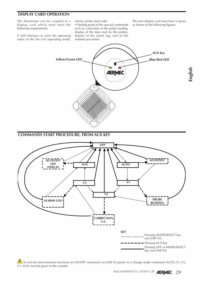
DISPLAY CARD OPERATION
COMMANDS START PROCEDURE, FROM AUX KEY
The thermostat can be coupled to a display card which must meet the following requirements:
• LED Interface to view the operating status of the fan coil (operating mode,
alarms, probe read-code)• Starting point of the special commands such as: correction of the probe reading, display of the data read by the probes, display of the alarm log, start of the Autotest procedure
The new display card must have a layout as shown in the following figures:
AUX key
Blue/Red LED Yellow/Green LED
To exit the test/correction functions an ON/OFF command (via VMF-E4 panel) or a change mode command (AUTO, V1, V2, V3, AUX) must be given to the cassette.
OFF
AUX
V3
V2
V1
AUTOAUTOTESTAUTOTEST
LEDDISPLAY
ALARMS LOG
CORRECTIONS.A.
PROBEREADING
KEYPressing MODE/SELECT key (see VMF-E4)
Pressing OFF or MODE/SELECT key (see VMF-E4)
Pressing AUX key

30
Engl
ish
AGLL10/20NFJ 07/11_4528571_00
AUTOTESTThe activation of the ventilation and the valve of the branch corresponding to the operating season, even in unsuitable water or environment temperature
conditions, can be "forced" in the self-test mode so as to verify the correct functioning of the connections and the windings of the electric motor.
PROBE READING
Values of the temperature probes acquired by the electronic card can be viewed through the yellow and red LED. In this mode the card enters in the Probe
Display mode. Initially the card displays the value of the Ambient probe SA.Press the AUX key normally to view other probes. The number of flashes by
the green LED indicates which probe is displayed (see table).
Green LED Probe displayed
2 SW probe
3 Aux SW probe
4 SA probe
5 Resistor probe SR
ALARMS LOG
The receiver cyclically indicates the last 5 alarms occurred on the machine in the "alarms log" view mode:
• yellow LED: cyclically flashes 5 times, and then remains off for 5 seconds
• red LED: lights at the same time as the yellow LED thereby providing a specific code
ALARM VISUALISATION
No alarm
Air probe faulty
Anti-freeze
Insufficient water
E4 interface not connected
Inverter fault
Resistor fault
condensate discharge
Motor fuse
Non-encoded signals
Key
Yellow LED
Red LED
AutotestPressing of the
AUX key
Pressing of the
AUX key
Pressing MODESELECT
Pressing MODESELECT
Pressing of the
AUX keyV1ON
V2ON
V3ON
Autotest Off

31
Engl
ish
AGLL10/20NFJ 07/11_4528571_00
AMBIENT PROBE READING CORRECTION
For installations of cassette fan coils that use the ambient probe positioned in the LED box, the correction of the probe reading may be deemed necessary to improve the thermostat adjustment.As for the other operations the correc-
tion of the probe can only be performed if the fan coil is in standby, the only difference is the selection of the correc-tion that is linked to the season of the thermostat.
SEASON TYPE OF PROBE CORRECTION
Ambient probe temperature - cold
Ambient probe temperature + hot
Parameters cold and hot can be dif-ferent from one another and can take integer values between 0 and 6 [°C].To set the hot value for example, the fan coil should be set to “winter” mode, and in standby: after pressing the AUX
key (see coding) the receiver goes into the "probe reading correction" mode dis-playing the amount of correction:
Key
LED off
Red LED
Blue LED
Green LED
LED status Correction coldhot [C°]
0
1
2
3
4
5
6

32
Engl
ish
AGLL10/20NFJ 07/11_4528571_00
Thermostat-controlled ventilation: The choice of the regulation according to thermostatically controlled ventilation (dip3 OFF) foresees the switching off of the ventilation when the setpoint is reached. (See the dip switch settings table).
Continuous ventilation: The continuous ventilation is selected by means of dip3 that must be set to On. In practice the continuous ventilation provides ventila-tion even with thermostat fulfilled at the
speed chosen. This function is disabled if the machine has no shut-off valve (dip1 OFF). In these particular cases, the ven-tilation will always be managed with thermostatically controlled logic.The following table shows the ventilation speed activated depending on the posi-tion of the selector:
Position Operations
OFFThe thermostat is off. It may however start again in Heating mode if the room temperature falls
below 7°C and the water temperature is suitable (anti-freeze function).
AUTO On reaching the setpoint, the ventilation proceedes with the minimum continuous speed.
V1In this position, the minimum ventilation speed V1 is always active regardless of thermostat
requirements.
V2In this position, the average ventilation speed V2 is always active regardless of thermostat
requirements.
V3In this position, the maximum ventilation speed V3 is always active regardless of thermostat
requirements.
AuxIn this position, the minimum Aux ventilation speed is alwaysactive.
VENTILATION CONTROL
If a shut-off valve is present (dip1 ON), the position of the probe can be man-aged both upstream and downstream of the valve itself (in the standard position on the heat exchanger). The main differ-ence between the two is in managing the ventilation in different ways. If the water probe is upstream of the valve (dip2 ON) or is not present, a heat exchanger pre-heating function occurs and enables the fan 2'40" after the first opening of the valve.The valve in question (for the heat exchanger pre-heating function) is Y1 if this is a 2-pipe system (dip5 Off), where-as if it is a 4-pipe system it is Y2 (dip5
On).The inhibition time of the fan is then automatically calculated and depends on how long the valve remains closed; in this way it could vary from a minimum of 0' 00" to a maximum of 2' 40". This ventilation enabling delay in relation to the opening of the valve is reset if the electric resistor is enabled, this is to ensure greater user safety.Refer to the specific table for the specific parameters of the dip switches.
VALVE OPERATION

33
Engl
ish
AGLL10/20NFJ 07/11_4528571_00
If the thermostat is configured for use without a valve (dip1 OFF) or with a probe upstream of the valve (dip2 ON), then the water temperature detected is that available on the terminal, there-fore the season is forced to Hot or Cold according to this temperature.The thresholds of the season changeover
are shown in the table below. In this configuration, the indications of the left LED correspond to the active mode.The ventilation is enabled only if the water temperature is suitable for the cooling mode or the heating mode. This allows on one side to avoid unwanted
cold ventilation in the winter season, and on the other side to check the turn-ing on and off of all terminals, accord-ing to the actual condition of the water available (centralized control of the On-Off and Hot-Cold commands).
The normal band (hot enabled at 39° C, cold enabled at 17° C) or the reduced band (hot enabled at 35° C, cold ena-bled at 22° C) is selected based on the (dip4).
The season changeover of some systems is based on air temperature, these are:
- 2-pipe systems with the Water Probe downstream of the valve.
- All 2-pipe systems without water probe.
- All 4-pipe systems.
The season changeover occurs as follows:
- Cold mode: if the ambient temperature
detected is below the setpoint of an interval equal to the dead band (2° C or 5° C) it switches to the hot mode.
- Hot mode: if the ambient temperature detected is above the setpoint of an interval equal to the dead band (2° C or 5° C) it switches to the cold mode.
The dead band is decided through
dip7 or rather if it has a dead band of 5° C (dip7 OFF) while if the dead band is 2° C (dip7 ON).
HOT/COLD MODE CHANGE OVER
COLD SEASON CHANGEOVER THRESHOLD
HOT SEASON CHANGEOVER THRESHOLD
DIP SWITCH MEANING
12 °C / 22°C 35 °C / 39 °C Normal band (dip 4 off)
22°C / 25°C 31 °C / 35°C Reduced band (dip 4 on)
WATER SIDE SEASON CHANGEOVER
SEASON CHANGEOVER BASED ON THE AIR
VENTILATION ENABLING
ANTI-FREEZE PROTECTION
The anti-freeze protection allows you to check that the room temperature never falls to freezing values (even when the selector is in the OFF position). If the temperature drops below 7° C, the ther-mostat still operates in HEATING mode with SETPOINT at 12° C and ventilation in AUTO, if the temperature of the water permits so. In case of Water Probe not present or continuous ventilation, the fan
is always enabled. If the valve is present and the water probe is upstream or the water probe is absent, the pre-heating of the heat exchanger is still executed.The thermostat exits the Anti-freeze mode when the room temperature exceeds 9°C.
The thermostat also includes an external contact that allows to set it to OFF if it is closed (except if the thermostat is in anti-freeze mode or as a slave in the TTL network). This contact could be useful to manage inputs such as window contacts, faulty circulation pump, etc.
CE input status Machine status
Closed OFF
Open ON
EXTERNAL CONTACT LOGIC
34
Engl
ish
AGLL10/20NFJ 07/11_4528571_00
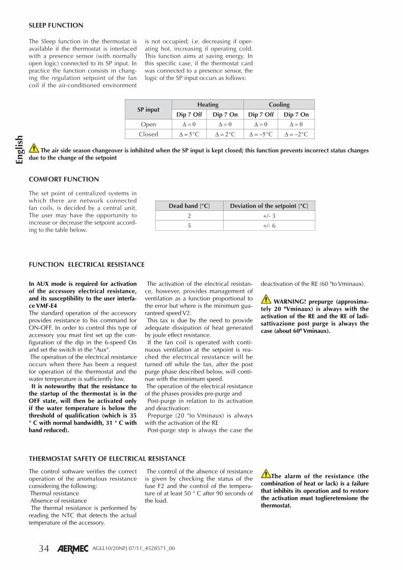
The set point of centralized systems in which there are network connected fan coils, is decided by a central unit. The user may have the opportunity to increase or decrease the setpoint accord-ing to the table below.
Dead band [°C] Deviation of the setpoint [°C]
2 +/- 3
5 +/- 6
The Sleep function in the thermostat is available if the thermostat is interfaced with a presence sensor (with normally open logic) connected to its SP input. In practice the function consists in chang-ing the regulation setpoint of the fan coil if the air-conditioned environment
is not occupied; i.e. decreasing if oper-ating hot, increasing if operating cold. This function aims at saving energy. In this specific case, if the thermostat card was connected to a presence sensor, the logic of the SP input occurs as follows:
SP inputHeating Cooling
Dip 7 Off Dip 7 On Dip 7 Off Dip 7 On
Open
Closed °C °C °C °C
SLEEP FUNCTION
COMFORT FUNCTION
The air side season changeover is inhibited when the SP input is kept closed; this function prevents incorrect status changes due to the change of the setpoint
In AUX mode is required for activation of the accessory electrical resistance, and its susceptibility to the user interfa-ce VMF-E4The standard operation of the accessory provides resistance to his command for ON-OFF. In order to control this type of accessory you must first set up the con-figuration of the dip in the 6-speed On and set the switch in the "Aux". The operation of the electrical resistance occurs when there has been a request for operation of the thermostat and the water temperature is sufficiently low. It is noteworthy that the resistance to the startup of the thermostat is in the OFF state, will then be activated only if the water temperature is below the threshold of qualification (which is 35 ° C with normal bandwidth, 31 ° C with band reduced).
The activation of the electrical resistan-ce, however, provides management of ventilation as a function proportional to the error but where is the minimum gua-ranteed speed V2. This tax is due by the need to provide adequate dissipation of heat generated by joule effect resistance. If the fan coil is operated with conti-nuous ventilation at the setpoint is rea-ched the electrical resistance will be turned off while the fan, after the post purge phase described below, will conti-nue with the minimum speed. The operation of the electrical resistance of the phases provides pre-purge and Post-purge in relation to its activation and deactivation: Prepurge (20 "to Vminaux) is always with the activation of the RE Post-purge step is always the case the
deactivation of the RE (60 "to Vminaux).
WARNING! prepurge (approxima-tely 20 "Vminaux) is always with the activation of the RE and the RE of ladi-sattivazione post purge is always the case (about 60" Vminaux).
The control software verifies the correct operation of the anomalous resistance considering the following: Thermal resistance Absence of resistance The thermal resistance is performed by reading the NTC that detects the actual temperature of the accessory.
The control of the absence of resistance is given by checking the status of the fuse F2 and the control of the tempera-ture of at least 50 ° C after 90 seconds of the load.
The alarm of the resistance (the combination of heat or lack) is a failure that inhibits its operation and to restore the activation must toglieretensione the thermostat.
FUNCTION ELECTRICAL RESISTANCE
THERMOSTAT SAFETY OF ELECTRICAL RESISTANCE

35
Engl
ish
AGLL10/20NFJ 07/11_4528571_00
ONOFF
1 2 3 4 5 6 7 8
ONOFF
1 2 3 4 5 6 7 8
ONOFF
1 2 3 4 5 6 7 8SW SW
SW
ONONOFF
1 2 3 4 5 6 7 8SW
ON
ON ONONOFF
1 2 3 4 5 6 7 8SW
ON
ONOFF
1 2 3 4 5 6 7 8SW
ON
SOME EXAMPLES:
VMF_E18 (default)
* Centralised control enabled
* Water p
FCXI 50 / 80FCXI 20 / 30 / 40
* With shutoff valve
DIP-SWITCH SETTINGTurn off the power to the unit. This operation should be carried out in the installation phase, by suitably trained and qualified personnel only. The dip-switches are on the electronic board.
**Warning: if the thermostats are inserted in systems with Centralised Control or Supervisor (e.g. VMF-E5), it is necessary to set: Dip1=ON and Dip2=OFF. The setting takes priority over the presence of the valve and the
position of the probe.
Position FunctionsDip 1 (Default OFF) Check water valve / * Thermostat in centralised network (See table):
OFF No shut-off valve
ON Shutoff valve present / * Thermostat in centralised network:
Dip 2 (Default OFF) Position water temperature probe / * Thermostat in centralised network (See table):
OFF Water temperature probe downstream from shutoff valve / *Thermostat in centralised network
ON Water temperature probe upstream from shutoff valve
Dip 3 (Default OFF) Ventilation control:
OFF Thermostat-controlled ventilation
ON Continuous ventilation
Dip 4 (Default OFF) Ventilation enabling:
OFF Enabling normal band
ON Enabling reduced band
Dip 5 (Default OFF) Machine with two or four pipes
OFF 2-pipe fan coils
ON 4-pipe fan coils
Dip 6 (Default OFF) the presence of the accessory
OFF Resistance to integration is not present
ON Presence of resistance to integration
Dip 7 (Default OFF) Dead band
OFF Dead band 5° C
ON Dead band 2° C
They can be used to obtain the following functions:

36
Engl
ish
AGLL10/20NFJ 07/11_4528571_00
ADDITIONAL CONTROLS
EMERGENCY FUNCTIONING
The ventilation in this case is always performed according to the ON-OFF cycles, however, increasing the ON phase from the central position. In this way the maximum ventilation can be required with the selector at the
minimum position for cooling opera-tion season and likewise there is maxi-mum ventilation with the selector in the maximum position. For the heating operation season. The total duration of the ON-OFF cycle is again 5’20’’. The
following table gives duration exam-ples of various ON and OFF cycles based on the position of the tempera-ture selector:
The two following failure cases are fore-seen when the thermostat operates in the described manner.
NO WATER PROBE - Ventilation is always active
- The season change is made on the basis of the difference between the set-ting made and the actual ambient tem-perature. If the ambient temperature exceeds by a value equal to the dead band, the Heating setpoint switches to the Cooling mode. If the ambient tem-perature drops by a value equal to the
dead band below the Cooling setpoint, it switches to the Heating mode.
- The turning on/off of the resistance does not depend in this case on the temperature of the water but on the sheer demand for the thermostat opera-tion
AMBIENT PROBE ABSENT (2 PIPES)In this case the thermostat operates as
follows:
- OFF - Aux Mode
The valve is closed
The fan is off
- AUTO, V1, V2, V3 mode:
The valve is always open.
Operating season always hot.
- The ventilation runs On-Off cycles. The duration of the ON cycle is pro-portional to the setpoint set in the VMF-E4 panel. The total duration of the ON-OFF cycle corresponds to 5’20’’. The following table gives dura-tion examples of various ON and OFF cycles based on the position of the temperature selector:
AMBIENT PROBE ABSENT (4 PIPES)In this case the thermostat operates as
follows:
- OFF - Aux Mode
The valves are closed
The fan is off
- AUTO, V1, V2, V3 mode:
The operating season is decided according to the position of the temper-ature selector and it is activated by the respective valve as shown in the Figure
SetPointON cycle duration
OFF cycle duration
Min value Nil '20"
20 C° 2'20" 2'60"
Max value '20" Nil
PositionON cycle duration
OFF cycle duration
Min value '20" Nil
20 C° Nil '20"
Max value '20" Nil
VENTILATION CYCLES OF 2-PIPE SYSTEM WITHOUT AMBIENT PROBE
VENTILATION CYCLE OF THE 4-PIPE SYSTEM WITHOUT AMBIENT PROBE
Keys used to modify the setpoint value
Cold water valve opening, ventilation period proportional to the deviation of the median position
Hot water valve opening, ventilation period proportional to the deviation
of the median position
Minimum value Maximum value
SETPOINT

37
Engl
ish
AGLLI10/20NFJ 07/11_4528572_00
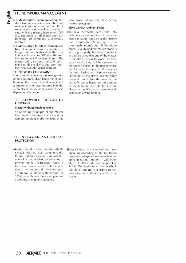
CASSETTE LOCAL NETWORKThe VMF-FCL thermostat has been de-signed to communicate with all thermo-stats of the VMF family through a dedicat-ed serial based on standard TTL logic and low throughput. This serial communica-tion is essential for the exchange of in-formation within small fan coil networks. This is in fact a network comprising no more than 6 thermostats with a maxi-mum length of about 30 meters. It was designed, in fact, for small areas where the fan coils (more than one) need to be controlled from a single control point. More specifi cally, this network always contains a Master (to which a user inter-face VMF-E4 is connected) that controls the operation of the Slaves connected to it, according to the settings made on its user interface.
OPERATING PRINCIPLE The fan coil master, or rather the one
with the VMF-E4 user interface con-nected, cyclically transmits the follow-ing information subsequently setting them on the slave units.
- Regulation Setpoint
- Operating mode (OFF, AUTO, V1, V2, V3, AUX) (on the On/Off machines)
- Operating season
Therefore the slave fan coils can not operate (except in particular cases) according to settings different from those dictated by the master.
AMBIENT PROBE: the ambient control probe is not needed on slave fan coils be-cause these can use the control probe of the master. However, if you want to avoid having micro-climates, it can be installed on the slaves that will then adjust with the respective probe. In particular cases where the ambient probe on the master is faulty, the slave without probe will op-erate in emergency mode (similar to the master), while the slaves with ambient probe will continue to operate normally.
WATER PROBE: the water temperature probe can be installed or not on the vari-ous fan coils of the TTL network. The fan coils with probe will use this for foreseen minimum and maximum values control, while the ventilation will always be ena-bled on the fan coils without water probe.
EXTERNAL CONTACT INPUT: this digi-tal input is inhibited on all slave fan coils while it is enabled on the master only. If the master input is closed, all the slave fan coils of the zone are switched off.
PRESENCE SENSOR INPUT: the presence sensor digital input is only active on the master fan coil
ANTI-FREEZE FUNCTION: the anti-freeze mode is the only case in which a slave that is in this status can operate according to settings are not provided by the master.
VMF-E4
FCLI SLAVE
FCLI SLAVE
FCLI MASTER
LUNGHEZZA MAX.30 (m)
38
Engl
ish
AGLLI10/20NFJ 07/11_4528572_00
TTL NETWORK ANTI-FREEZE PROTECTION
Master: As described in the ANTI-FREEZE PROTECTION paragraph, the thermostat foresees as standard the control of the ambient temperature to prevent this fall to freezing values. If the master has to operate in this condi-tion, it will impose all slaves to oper-ate in AUTO mode with setpoint at 12° C, even though these are operating according to normal conditions.
Slave: Whereas if it is one of the slaves operating according to the anti-freeze protection (despite the master is oper-ating in normal mode), it will oper-ate in AUTO mode with setpoint at 12° C. This is the only case in which the slave operates according to set-tings different to those dictated by the master.
TTL NETWORK MANAGEMENT
No Master-Slave communication: the slave fan coil cyclically await the zone settings from the master fan coil. If for some reason a slave fails to communi-cate with the master, it switches OFF (i.e. shutdown of all loads) after 10" from the last command successfully received.
No Master-User Interface communica-tion: if at some point the master no longer communicates with the user interface, it switches OFF after 10" from the last command received from it. The master will also send the OFF com-mand to all the slaves. The user inter-face also gives the visual alarm AL 1
TTL NETWORK CONSTRAINTSThe constraint concerns the management of the adjustment dead band; this should be set on the master fan coil being that it is ignored on the slaves because both the setpoint and the operating season of these depend on the master.
T T L N E T W O R K E M E R G E N C Y FUNCTION
Master without Ambient Probe
The operating principle of the master thermostat in the event that it functions without ambient probe (or fault of its
local probe) follows what described in the next paragraph.
Slave without Ambient Probe
The Slave thermostat cards enter into emergency mode not only if the local probe is faulty but also if the master one is faulty too. According to what previously mentioned, if the slave probe is faulty and the master probe is working properly, the slaves continue to operate using that one of the master. If the slaves begin to work in emer-gency mode, they will be operated at the speed selected in the user interface and the valve Y1 is opened (this applies for both 2-pipe and 4-pipe system). Furthermore, the slaves in emergency mode do not follow the logic of the ON-OFF cycles based on the position of the temperature selector but are always in the ON phase, therefore with ventilation always running.

39
Engl
ish
AGLL10/20NFJ 07/11_4528571_00
INSTALLATION
WARNING: check that the power sup-ply is disconnected before carrying out any procedures on the unit.
WARNING: before carrying out any work, put the proper individual pro-tection devices on.
WARNING: the device must be installed in compliance with the national plant engineering rules.
WARNING: the electrical connections, the installation of the fan coils and relevant accessories should be per-formed by a technician who has the necessary technical and professional expertise to install, modify, extend and maintain systems, and who is able to check the systems for the purposes of safety and correct operation (in this manual they will be indicated with the general term "persons with specific technical skills").
In the specific case of electrical wirings, the following must be checked:
- measurement of the electrical system insulation strength
- continuity test of the protection wires
WARNING: install a device, main switch, or electric plug so you can fully disconnect the device from the power supply.
The essential indications to install the device correctly are given here.
The completion of all the operations in accordance with the specific require-ments is however left to the experience of the installation engineer.
See also the installation manual of the FCLI unit and the user's manual pro-vided with the grille unit.
Generally the best position of the fins is that which allows the launch of the air adhering to the ceiling for the coined effect, during cold functioning.
The opening positions are indicated on the side section of the deflectors (GLL10N) for correct machine heating (20° opening) and cooling (10° open-ing) operation.
For units with GLL20N grilles the deflec-tor should be fully opened in the heat-ing operation and it should be rotated halfway in the cooling operation.
Depending on the user's needs, the fins can be adjusted to the intermediate positions, or completely closed. Thanks to the special shapes of the fins, the machine can also function with the deflectors completely closed.
Do not install at a height above three metres.
The FCLI unit is prepared for connec-tions with channelling for the fresh air and for the delivery of treated air to an adjacent room.
• INSTALLING NEAR A WALL
If the unit is to be installed near a wall, the corresponding delivery outlet can be closed using the gasket supplied.
ELECTRICAL WIRINGSThe unit must be connected directly
to an electrical outlet or to an independent circuit.
The FCLI cassette-type fan coils must be powered with a current of 230V ~50Hz with an earth connection; the line voltage must however remain within the tolerance of ±10% compared with the nominal value.
To protect the unit against short circuits, fit an omnipolar thermal trip max. 2A 250V (IG) to the power line with a minimum contact opening distance of 3 mm.
The electrical power cable must be of the H07 V-K or N07 V-K type with 450/750V insulation if inside a tube or raceway. Use cables with double H5vv-F type insulation for visible cable installation.
For all the connections, follow the wiring diagrams supplied with the device and shown in this documentation.
The electric box is supplied with obligatory accessories (GLLI - GLLI_N).

40
Engl
ish
AGLL10/20NFJ 07/11_4528571_00
FAILURE OF THE THERMOSTAT FUSES AND REPLACEMENT
The installation and the electri-cal connections of the units and their accessories must only be carried out by people possessing the technical/professional requisites for system installation, transformation, extension and maintenance, and who are able to check these aspects for the purposes of safety and correct operation. They will be generically referred to in this manu-al as "Personnel with specific technical skills". Check that the power supply is disconnected before carrying out any procedures on the unit.
If the fuses are burnt and for possible replacement:
• Remove the delivery frame
• Extract the thermostat card
• Open the thermostat box
• Replace the faulty fuses
The fuses are 5 x 20 T series (delayed) from 2 A to 10 A
• WARNING: for correct replacement, the 2 A fuse must be inserted in loca-tion F3, while the 10 A fuse must be inserted in F2, as shown in the image below.
Before installing the electric box, the configuration of the electronic board dip-switches needs to be checked in order to adjust the board to the system.
Connect the VMF-E4 control panel, supervision network cable, TTL
network cable, and probe and valve cables based on system requirements.
For the connections, refer to the wiring diagrams of the fan coil and connected accessories.
GLLI10NGLLI20N
ELECTRICAL CONNECTIONS WITH GLLI10N AND GLLI20N ACCESSORIES
- L -
N
> 65
0mm
230VAC
LN
230VACLN
VMF-SW1
CN3
F2
F3

95
Espa
ñol
Espa
ñol
Espa
ñol
Espa
ñol
Espa
ñol
AGLL10/20NFJ 07/11_4528571_00
AL • Supply = Alimentatore Power supply Alimentation electrique Spannung Alimentador
AMP=Contatto allarme pompa scarico condensa
Contact alarm condensate pump discharge
Contact d'alarme de décharge de pompe condensat
Kontakt Alarm Kondensatpumpe Entlastung
Contacto de alarma de bomba de descarga de condensados
CE = Contatto esterno
CN = Connettore Connector Connecteur Schütz Conector
F = Fusibile • Fuse • Fusible Sicherung • Fusible
IG = Interruttore generale Main switch Interupteur général Hauptschalter Interruptor general
M = Morsettiera Terminal board Boitier Klemmleiste Placa de bornes
MP = Pompa scarico condensa Condensate drain pump Pompe de vidange du condensat Kondensatablass Pumpe
Bomba de desagüe de condensado
MV = Motore ventilatore • Fan motor Moteur ventilateur • Ventilatormotor Motor del ventilador
PE = Collegamento a terra GND Earth connection Mise à terre Erdanschluss Toma de tierra
SA = Sonda temperatura aria Air temperature probe Sonde temp. de l'air Temperaturfühler Sonda temperatura del aire
SW1 = Dip Switch
SW (CN2) = (SW4) Sonda temperatura acqua Water temperature probe Sonde temp. eau Wasserfühler Sonda temperatura del agua
SW (CN3) = (VMF-SW1) Sonda temperatura acqua (impianti 4 tubi) Water temperature probe (4-pipe version) Sonde temp. eau (systèmes à 4 tuyaux) Wasserfühler (4-Leiter-Systemen) Sonda temperatura del agua (instalaciones de 4 tubos)
VHL =Valvola Valve Vanne Ventil Válvula
= Componenti non forniti Components not supplied Composants non fournis Nicht lieferbare Teile Componentes no suministrados
= Componenti forniti optional Optional components Composants en option Optionsteile Componentes opcionales
=Collegamenti da eseguire in loco On-site wiring Raccordements à effectuer in situ Vor Ort auszuführende Anschlüsse Cableado in situ
LEGENDA • READING KEY • LEGENDE • LEGENDE • LEYENDA
SCHEMI ELETTRICI • WIRING DIAGRAMS • SCHEMAS ELECTRIQUES • SCHALTPLÄNE • ESQUEMAS ELÉCTRICOS
AR = Arancio • Orange • Orange • Orange • Naranja
BI = Bianco • White • Blanc • Weiss • Blanco
BL = Blu • Blue • Bleu • Blau • Azul
GR = Grigio • Grey • Gris • Gray • Gris
MA = Marrone • Brown • Marron • Braun • Marrón
NE = Nero • Black • Noir • Schwarz • Negro
RO = Rosso • Red • Rouge • Rot • Rojo
ROS = Rosa • Pink • Rose • Rosa • Rosa
VE = Verde • Green • Vert • Grün • Verde
VI = Viola • Violet • Violet • Violet • Violeta
Gli schemi elettrici sono soggetti ad un continuo aggiornamento, è obbligatorio quindi fare riferimento a quelli a bordo macchina.A l l w i r i n g d i a g r a m s a r e c o n s t a n t l y u p d a t e d . P l e a s e r e f e r t o t h e o n e s s u p p l i e d w i t h t h e u n i t .Nos schémas électr iques étant constamment mis à jour, i l faut absolument se référer à ceux fournis à bord de nos apparei ls .Die Schaltpläne werden ständig aktualisiert, deswegen muss man sich stets auf das mit dem Gerät gelieferte Schaltschema beziehen.El cableado de las máquinas es sometido a actualizaciones constantes. Por favor, para cada unidad hagan referencia a los esquemas suministrados con la misma.

96
Espa
ñol
Espa
ñol
Espa
ñol
Espa
ñol
Espa
ñol
AGLL10/20NFJ 07/11_4528571_00
SCHEMI ELETTRICI • WIRING DIAGRAMS • SCHEMAS ELECTRIQUES • SCHALTPLÄNE • ESQUEMAS ELÉCTRICOS
Gli schemi elettrici sono soggetti ad un continuo aggiornamento, è obbligatorio quindi fare riferimento a quelli a bordo macchina.A l l w i r i n g d i a g r a m s a r e c o n s t a n t l y u p d a t e d . P l e a s e r e f e r t o t h e o n e s s u p p l i e d w i t h t h e u n i t .Nos schémas électr iques étant constamment mis à jour, i l faut absolument se référer à ceux fournis à bord de nos apparei ls .Die Schaltpläne werden ständig aktualisiert, deswegen muss man sich stets auf das mit dem Gerät gelieferte Schaltschema beziehen.El cableado de las máquinas es sometido a actualizaciones constantes. Por favor, para cada unidad hagan referencia a los esquemas suministrados con la misma.
FCLGLL10N / GLL20N
SALED
CEGNDCFABGND
RS485TX/RX
GND
TTL
BL1
,57
MA
1,5
1M
MP
VHL
4 3 2 1
F 10
AF
2A
+
RL1 RL2 RL3RL4 RL5 RL6
RL7
LNN AU
X/R
E
MAY2Y1N1V3V2V1 N
TR1
M28
M14
M27
C1
M25
M22
CN
2C
N1
CN3
L17
M21
M19
M20
M18
M17
M16
M15
M3
F2F3
L N
123456
123456
TX/RX
5VMODE
GND-TTL
31818
5 16 88
9 22
11
1515
NE
MA
GR
RO
BI
BI
VI
AR
1212
1313
1111
66
1717
MA
MA
1,5
BL
1,5
1010 3
44
1414
7
AM
P
BL
NE
NE
5 16 9
MA
X
NE
ALT
A
ME
D
MIN
11
3 44
M1
55
66
22
MV
MAROGR BL
3N
E
MA BL
GR
RO
12
12
3
4 3
4
SR RXL
4 3 2 1
Dis.4818570_03
MA
1,5
BL
230V 50Hz
NLIG
PE
VHL1VHL20VHL2VHL22
BL
BL
1
SW1
SW4
WMF-SW1
1 2 3 4
1 2 3 4E4

97
Espa
ñol
Espa
ñol
Espa
ñol
Espa
ñol
Espa
ñol
AGLL10/20NFJ 07/11_4528571_00
SCHEMI ELETTRICI • WIRING DIAGRAMS • SCHEMAS ELECTRIQUES • SCHALTPLÄNE • ESQUEMAS ELÉCTRICOS
Gli schemi elettrici sono soggetti ad un continuo aggiornamento, è obbligatorio quindi fare riferimento a quelli a bordo macchina.A l l w i r i n g d i a g r a m s a r e c o n s t a n t l y u p d a t e d . P l e a s e r e f e r t o t h e o n e s s u p p l i e d w i t h t h e u n i t .Nos schémas électr iques étant constamment mis à jour, i l faut absolument se référer à ceux fournis à bord de nos apparei ls .Die Schaltpläne werden ständig aktualisiert, deswegen muss man sich stets auf das mit dem Gerät gelieferte Schaltschema beziehen.El cableado de las máquinas es sometido a actualizaciones constantes. Por favor, para cada unidad hagan referencia a los esquemas suministrados con la misma.
FCLGLL10N / GLL20N
CEGNDCFABGND
RS485TX/RX
GND
TTL
BL1
,57
MA
1,5
1M
MP
4 3 2 1
F 10
AF
2A
+
RL1 RL2 RL3RL4 RL5 RL6
RL7
LNN AU
X/R
E
MAY2Y1N1V3V2V1 N
TR1
M28
M14
M27
C1
M25
M22
CN
2C
N1
CN3
L17
M21
M19
M20
M18
M17
M16
M15
M3
F2F3
L N
123456
123456
TX/RX
5VMODE
GND-TTL
31818
5 16 88
9 22
11
1515
NE
MA
GR
RO
BI
BI
VI
AR
1212
1313
1111
66
1717
MA
MA
1,5
BL
1,5
1010 3
44
1414
7
AM
P
BL
NE
NE
5 16 9
MA
X
NE
ALT
A
ME
D
MIN
11
3 44
M1
55
66
22
MV
MAROGR BL
3N
E
MA BL
GR
RO
12
12
3
4 3
4
SR RXL
4 3 2 1
Dis.4818571_03
MA
1,5
BL
230V 50Hz
NLIG
PE
BL
BL
1
SW1
SW4
WMF-SW1
1 2 3 4
1 2 3 4E4
VHL1VHL20VHL2VHL22
FCL_VL
SALED

AERMEC S.p.A.I-37040 Bevilacqua (VR) - ItaliaVia Roma, 996 - Tel. (+39) 0442 633111Telefax (+39) 0442 93730 - (+39) 0442 93566www .aermec. com
I dati tecnici riportati nella presente documentazione non sono impegnativi.AERMEC S.p.A. si riserva la facoltà di apportare in qualsiasi momento tutte le modifiche ritenute necessarie per il miglioramento del prodotto.Les données mentionnées dans ce manuel ne constituent aucun engagement de notre part. Aermec S.p.A. se réserve le droit de modifier à tous moments les données considérées nécessaires à l’amelioration du produit.Technical data shown in this booklet are not binding.Aermec S.p.A. shall have the right to introduce at any time whatever modifications deemed necessary to the improvement of the product.Im Sinne des technischen Fortsschrittes behält sich Aermec S.p.A. vor, in der Produktion Änderungen und Verbesserungen ohne Ankündigung dur-chzuführen.ILos datos técnicos indicados en la presente documentación no son vinculantes.Aermec S.p.A. se reserva el derecho de realizar en cualquier momento las modificaciones que estime necesarias para mejorar el producto.