core and fuel design chapter chapter ore and 6 fuel designcetnar/abwr/chapter6.pdf · 6-1 chapter 6...
TRANSCRIPT

CHAPTER 6 — CORE AND FUEL DESIGN
6-1
6ChapterCore and Fuel Design
Introduction and SummaryThe design of the Advanced Boiling Water Reactor(ABWR) core and fuel is based on the propercombination of many design variables and operatingexperience. These factors contribute to theachievement of high reliability, excellent performance,and improved fuel cycle economics.
The core and fuel design methods employed for designanalyses and calculations have been verified bycomparison with data from operating plants, gammascan measurements, testing facilities, and Monte Carloneutron transport calculations. GE continuallyimplements advanced core and fuel design technology,such as control cell core, spectral shift operation,axially varying gadolinia and enrichment zoning, fuelcladding with improved corrosion resistance, partlength fuel rods, interactive channels, and wider watergaps in the ABWR core. As these technologicalimprovements are added, the core and fuel designparameters are optimized to achieve better fuel cycleeconomics, while improving fuel integrity andreliability and while maintaining overall reactor safety.
The reactor lattice configuration and fuel elementdesign for the ABWR are basically the same asemployed in previous GE designed plants operatingaround the world. Key features of the ABWR reactorcore design are summarized in the followingparagraphs:
• The ABWR core mechanical design is based onconservative application of stress limits, operatingexperience, and experimental test results. Themoderate pressure levels characteristic of a direct
cycle reactor, approximately 1000psia (6900 kPa), reduce claddingtemperatures and stress levels.
• The low coolant saturationtemperature, high heat transfercoefficients, and neutral waterchemistry of the ABWRare significant, advantageousfactors in minimizing Zircaloy cladtemperature and associatedtemperature-dependent corrosionand hydride buildup. This resultsin improved cladding performanceat high burnup.
• The basic thermal and mechanicalcriteria applied in the ABWRdesign have been proven byirradiation of statisticallysignificant quantities of fuel. Thedesign heat fluxes and linear heatgeneration rates are similar tovalues proven in fuel assemblyirradiation in the large fleet ofoperating BWRs.
• Because of the large negativemoderator density (void)coefficient of reactivity, theABWR has a number of inherentadvantages, including (1) ease ofcontrol using coolant flow asopposed to control rods for loadfollowing, (2) inherent self-flattening of the radial powerdistribution, (3) spatial xenonstability, and (4) ability to overridexenon in order to follow load. The

CHAPTER 6 — CORE AND FUEL DESIGN
6-2
inherent spatial xenon stability ofthe ABWR is particularlyimportant for large-sized plants,and permits daily load followingover a large range of core powerlevels.
• The power density (approximately50 kW/l) and power distributionsused in sizing the ABWR coreincludes margins providing foroperational flexibility.
• The ABWR fuel assembly pitch is0.1 inch more than theconventional BWR fuel assemblypitch so that it can accommodatemore water in the bypass gapsbetween the fuel assemblies,which improves fuel utilizationand core thermal hydraulicstability and results in milderresponse for pressurizationtransients.
Core Configuration
The reactor core of the ABWR isarranged as an upright cylindercontaining a large number of fuelassemblies (872) located within thereactor vessel. The coolant flowsupward through the core. The corearrangement (plan view) and the latticeconfiguration are shown in Figures6-1 and 6-2, respectively. Importantcomponents of this arrangement aredescribed in the following pages.
As can be seen from Figure 6-1, theABWR reactor core is comprised offuel assemblies, control rods andnuclear instrumentation. The fuelassembly and control rod mechanical
designs are basically the same as used in all but theearliest GE boiling water reactors; however,evolutionary improvements have been made to thesecomponents throughout the history of the GE BWR.The current generation of these components will bedescribed below for application to the ABWR.
GE14 Fuel AssemblyDescription
The BWR fuel assembly consists of a fuel bundle anda channel. The fuel bundle contains the fuel rods andthe hardware necessary to support and maintain theproper spacing between the fuel rods. The channel isa Zircaloy box which surrounds the fuel bundle todirect the core coolant flow through the bundle andalso serves to guide the movable control rods.
The GE14 product line is currently GE’s mostadvanced fuel assembly design. With the introductionof GE14, GE offers the widest selection of BWR fueldesigns in the industry. Utilities can choose from fivedifferent designs (GE10 to GE14) to achieve the fuelcharacteristics that best match their ABWR operatingstrategy. The GE10 bundle contains 60 fuel rods andone large central water rod in an 8x8 array. The GE11and GE13 designs contain a 9x9 array of 66 full lengthfuel rods, 8 part length fuel rods which span roughlytwo-thirds of the active core, and two large centralwater rods. The GE12 and GE14 designs contain a10x10 array of 78 full length fuel rods, 14 part lengthrods, and two large central water rods. Thus, GEprovides 8x8, 9x9 and 10x10 fuel designs for theABWR.
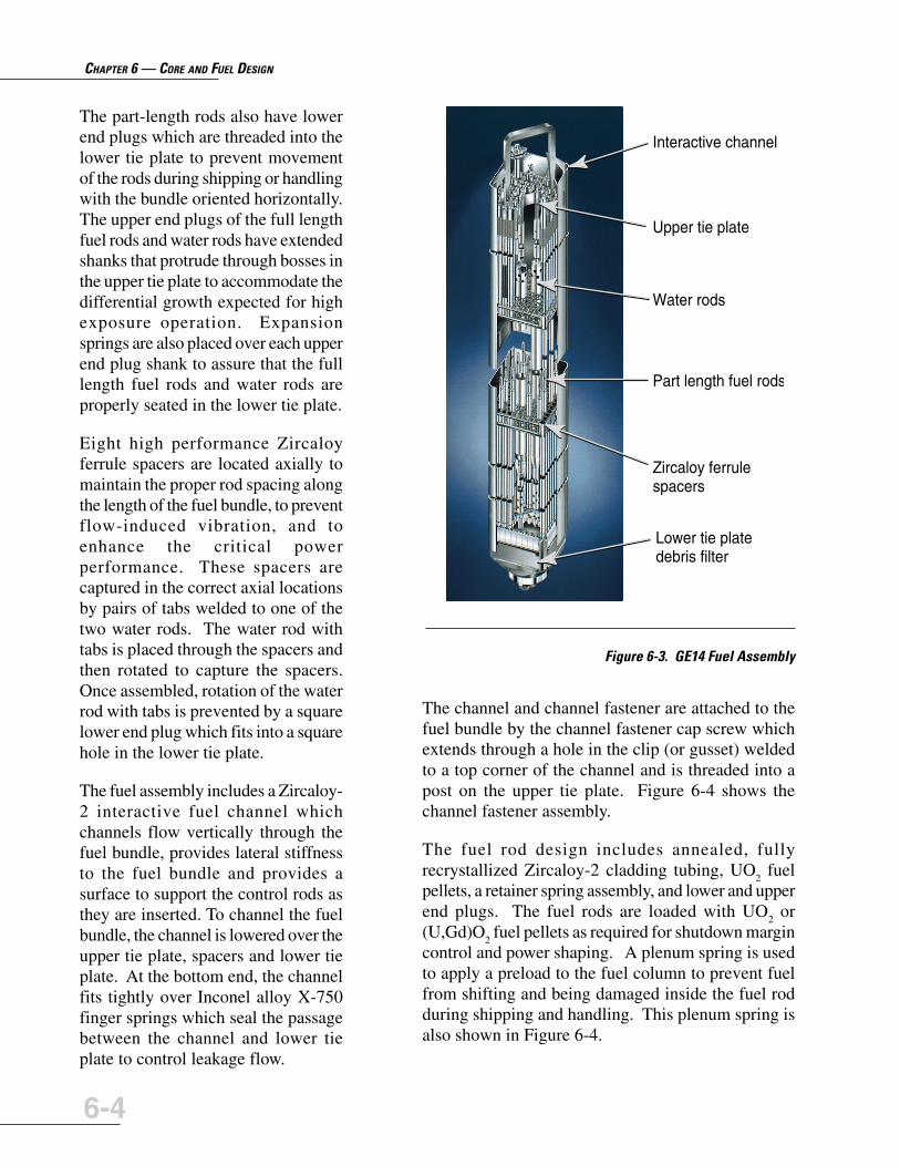
Figure 6-3 shows the GE14 design with the majorcomponents identified. The cast stainless steel lowertie plate includes a conical section which seats intothe fuel support and a grid which maintains the properfuel rod spacing at the bottom of the bundle. The cast

CHAPTER 6 — CORE AND FUEL DESIGN
6-3
Figure 6-1. ABWR Core Configuration
���
�����
�����
���
��FUEL ROD TIE ROD
WATER ROD PART LENGTH ROD
Fuel Assembly
Control Cell Fuel Assembly
Peripheral Fuel Assembly
Control Rod Assembly
LPRM Assembly
Figure 6-2. Four Bundle Fuel Module (Cell)
stainless steel upper tie plate maintainsthe fuel rod spacing at the top of thebundle and provides the handle that isused to lift the bundle.
The fuel bundle assembly is heldtogether by eight tie rods locatedaround the periphery of the fuelbundle. Each tie rod has a threadedlower end plug which screws into thelower tie plate and a threaded upperend plug which extends through a bossin the upper tie plate and is fastenedwith a nut. A lock tab washer isincluded under the tie rod nut toprevent rotation of the tie rod and nut.
CHAPTER 6 — CORE AND FUEL DESIGN
6-4
The part-length rods also have lowerend plugs which are threaded into thelower tie plate to prevent movementof the rods during shipping or handlingwith the bundle oriented horizontally.The upper end plugs of the full lengthfuel rods and water rods have extendedshanks that protrude through bosses inthe upper tie plate to accommodate thedifferential growth expected for highexposure operation. Expansionsprings are also placed over each upperend plug shank to assure that the fulllength fuel rods and water rods areproperly seated in the lower tie plate.
Eight high performance Zircaloyferrule spacers are located axially tomaintain the proper rod spacing alongthe length of the fuel bundle, to preventflow-induced vibration, and toenhance the critical powerperformance. These spacers arecaptured in the correct axial locationsby pairs of tabs welded to one of thetwo water rods. The water rod withtabs is placed through the spacers andthen rotated to capture the spacers.Once assembled, rotation of the waterrod with tabs is prevented by a squarelower end plug which fits into a squarehole in the lower tie plate.
The fuel assembly includes a Zircaloy-2 interactive fuel channel whichchannels flow vertically through thefuel bundle, provides lateral stiffnessto the fuel bundle and provides asurface to support the control rods asthey are inserted. To channel the fuelbundle, the channel is lowered over theupper tie plate, spacers and lower tieplate. At the bottom end, the channelfits tightly over Inconel alloy X-750finger springs which seal the passagebetween the channel and lower tieplate to control leakage flow.
The channel and channel fastener are attached to thefuel bundle by the channel fastener cap screw whichextends through a hole in the clip (or gusset) weldedto a top corner of the channel and is threaded into apost on the upper tie plate. Figure 6-4 shows thechannel fastener assembly.
The fuel rod design includes annealed, fullyrecrystallized Zircaloy-2 cladding tubing, UO
2 fuel
pellets, a retainer spring assembly, and lower and upperend plugs. The fuel rods are loaded with UO
2 or
(U,Gd)O2 fuel pellets as required for shutdown margin
control and power shaping. A plenum spring is usedto apply a preload to the fuel column to prevent fuelfrom shifting and being damaged inside the fuel rodduring shipping and handling. This plenum spring isalso shown in Figure 6-4.
Figure 6-3. GE14 Fuel Assembly
Interactive channel
Upper tie plate
Water rods
Part length fuel rods
Zircaloy ferrulespacers
Lower tie platedebris filter

CHAPTER 6 — CORE AND FUEL DESIGN
6-5
The lower end plug is welded to the lower end of thecladding before loading any of the internal fuel rodcomponents mentioned above. After loading allinternal components, the fuel rod is evacuated, thenbackfilled with helium. The upper end plug is insertedinto the top end of the fuel rod, compressing theretainer spring, and welded to the cladding.
Key Fuel Design FeaturesThe GE14 design utilizes several keydesign features, including part-lengthfuel rods, high performance spacers,low pressure drop upper tie plate, highpressure drop lower tie plate withdebris filter, large central water rods,and interactive channels. These keydesign features are individuallydiscussed below.
Part Length RodsPart length fuel rods (PLRs) wereintroduced with the GE11 fuel designand have been used in all subsequentGE designs. For GE14, the 14 PLRsterminate just above the fifth spacer toprovide increased flow area and reducethe two-phase pressure drop. Thisreduction in two-phase pressure dropleads to an improvement in core andchannel stability and allows for anincrease in the cladding diameter tomaximize the fuel weight for a givenoverall pressure drop. In addition, thePLRs increase the moderator to fuelratio in the top of the core to improvecold shutdown margins and fuelefficiency.
High Performance SpacersThe high performance Zircaloy ferrulespacer was developed to provideexcellent critical power performancewith acceptable pressure dropcharacteristics. This spacer concept isalso used in GE10, GE11, and GE13.Eight spacers are used to maintain rodbow and flow-induced vibrationmargins for the reduced diameter10x10 fuel rods of the GE14 design,while at the same time providingadditional critical power capability.
Figure 6-4. Channel Fastener Assembly
CHANNELFASTENERASSEMBLY
CHANNEL
SPRING(2 SIDES)
CAPSCREW
UPPERTIE PLATE
EXPANSIONSPRING
PLENUMSPRING
FUELROD
GUARD(2 SIDES)
FUELCLADDING
FUELPELLET

CHAPTER 6 — CORE AND FUEL DESIGN
6-6
Low Pressure Drop UpperTie PlateThe upper tie plate (UTP) is designedto minimize two-phase pressure dropto improve fuel stability performanceand reduce the pumping powerrequired to drive core flow.
High Pressure Drop Lower TiePlate with Debris FilterAs discussed previously, the use ofpart length rods and the low pressuredrop upper tie plates to reduce two-phase pressure drop allows for anincrease in single-phase pressure dropat the lower tie plate. This tradeoffprovides improved stability withessentially the same overall pressuredrop as previous designs. In addition,it allows for the use of very small flowholes in the lower tie plate, which actas a very effective debris filter. Figure6-5 shows a top view of the debrisfilter lower tie plate. The bundle flowpasses through the small holes whichare only 0.125 inches in diameter, andof which there are 444. The debrisfilter lower tie plate design is standardwith the GE14 design, and has beenprovided as an option for the GE11through GE13 designs.
Large Central Water RodsOne of the basic characteristics of aBWR is that it is under-moderated atoperating temperatures. In order toimprove moderation and fuelefficiency, fuel rods are removed fromthe center of the fuel bundle andreplaced with water rods to provide azone for non-boiling water flow. TheGE14 design includes two largecentral water rods to replace eight fuelrod locations and provide improvedmoderation.
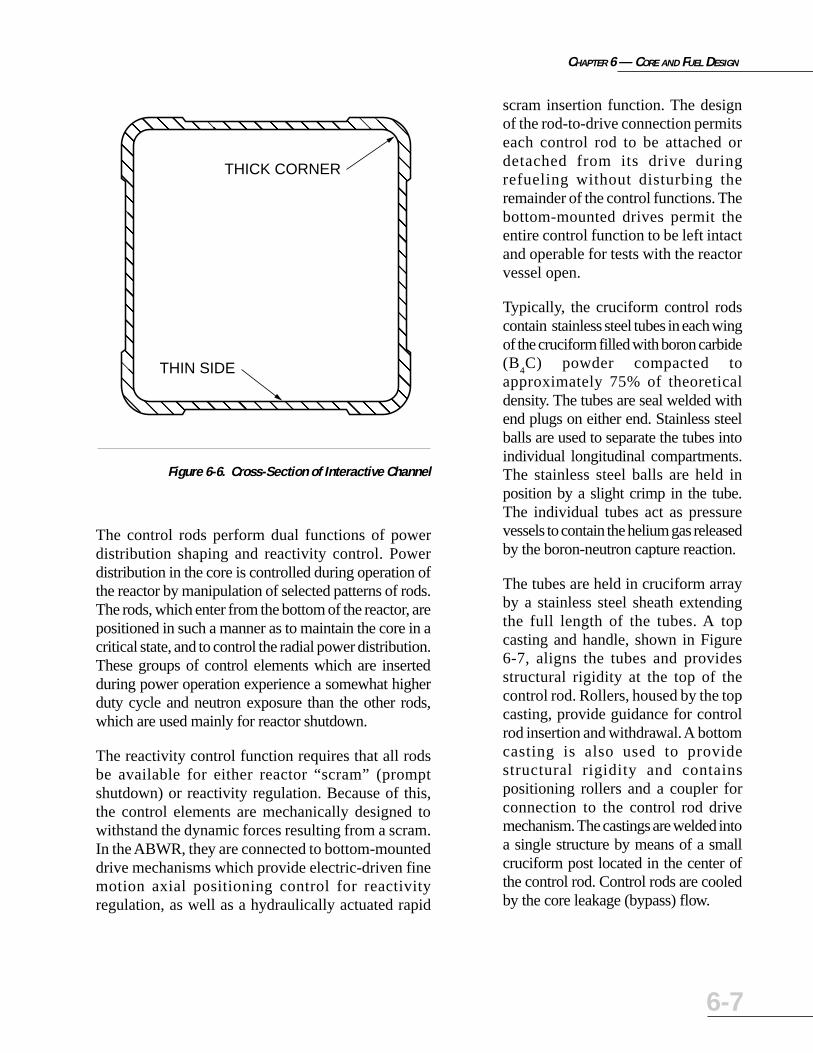
Interactive ChannelsThe interactive fuel channel concept used with theGE10 through GE13 fuel bundles is also included asan integral part of the GE14 design. This channeldesign has an optimized cross section, as illustratedin Figure 6-6, which includes thick corners wherestresses are highest and thinner flat sides where stressesare low. This design minimizes the amount ofZircaloy-2 material in the channel in order to improvenuclear efficiency, increases the moderator in thebypass region for improved reactivity and hot-to-coldswing, and increases the control rod clearance.
Control Rod Descriptions
As shown in Figures 6-1 and 6-2, cruciform shapedcontrol rods are configured for insertion between everyfour fuel assemblies comprising a module or “cell”.The four assemblies in a cell provide guidance forinsertion and withdrawal of the control rods.
Figure 6-5. Top View of GE14 Debris Filter Lower Tie Plate
CHAPTER 6 — CORE AND FUEL DESIGN
6-7
The control rods perform dual functions of powerdistribution shaping and reactivity control. Powerdistribution in the core is controlled during operation ofthe reactor by manipulation of selected patterns of rods.The rods, which enter from the bottom of the reactor, arepositioned in such a manner as to maintain the core in acritical state, and to control the radial power distribution.These groups of control elements which are insertedduring power operation experience a somewhat higherduty cycle and neutron exposure than the other rods,which are used mainly for reactor shutdown.
The reactivity control function requires that all rodsbe available for either reactor “scram” (promptshutdown) or reactivity regulation. Because of this,the control elements are mechanically designed towithstand the dynamic forces resulting from a scram.In the ABWR, they are connected to bottom-mounteddrive mechanisms which provide electric-driven finemotion axial positioning control for reactivityregulation, as well as a hydraulically actuated rapid
scram insertion function. The designof the rod-to-drive connection permitseach control rod to be attached ordetached from its drive duringrefueling without disturbing theremainder of the control functions. Thebottom-mounted drives permit theentire control function to be left intactand operable for tests with the reactorvessel open.
Typically, the cruciform control rodscontain stainless steel tubes in each wingof the cruciform filled with boron carbide(B
4C) powder compacted to
approximately 75% of theoreticaldensity. The tubes are seal welded withend plugs on either end. Stainless steelballs are used to separate the tubes intoindividual longitudinal compartments.The stainless steel balls are held inposition by a slight crimp in the tube.The individual tubes act as pressurevessels to contain the helium gas releasedby the boron-neutron capture reaction.
The tubes are held in cruciform arrayby a stainless steel sheath extendingthe full length of the tubes. A topcasting and handle, shown in Figure6-7, aligns the tubes and providesstructural rigidity at the top of thecontrol rod. Rollers, housed by the topcasting, provide guidance for controlrod insertion and withdrawal. A bottomcasting is also used to providestructural rigidity and containspositioning rollers and a coupler forconnection to the control rod drivemechanism. The castings are welded intoa single structure by means of a smallcruciform post located in the center ofthe control rod. Control rods are cooledby the core leakage (bypass) flow.
Figure 6-6. Cross-Section of Interactive Channel
�
���
���
�
��
����
���
�
��
����
���
�
�
���
�����
���
�
��
����
��
��
����
��
�
���
���
�
�
���
����
��
�
���
����
��
@
@@@
@@@
@
AA
AAAA
AAA
A
BB
BBBB
BBB
B
C
CCC
CCCCC
CCC
C
DD
DDDD
DD
EE
EEEE
EE
F
FFF
FFF
F
G
GGG
GGGG
GG
H
HHH
HHHH
HH
�
���
���
�
��
����
���
�
��
����
���
�
�
���
�����
���
�
��
����
��
��
����
��
�
���
���
�
�
���
����
��
�
���
����
��
À
ÀÀÀ
ÀÀÀ
À
ÁÁ
ÁÁÁÁ
ÁÁÁ
Á
ÂÂ
ÂÂÂÂ
ÂÂÂ
Â
Ã
ÃÃÃ
ÃÃÃÃÃ
ÃÃÃ
Ã
ÄÄ
ÄÄÄÄ
ÄÄ
ÅÅ
ÅÅÅÅ
ÅÅ
Æ
ÆÆÆ
ÆÆÆ
Æ
Ç
ÇÇÇ
ÇÇÇÇ
ÇÇ
È
ÈÈÈ
ÈÈÈÈ
ÈÈ
�
���
���
�
��
����
���
�
��
����
���
�
�
���
�����
���
�
��
����
��
��
����
��
�
���
���
�
�
���
����
��
�
���
����
��
@
@@@
@@@
@
AA
AAAA
AAA
A
BB
BBBB
BBB
B
C
CCC
CCCCC
CCC
C
DD
DDDD
DD
EE
EEEE
EE
F
FFF
FFF
F
G
GGG
GGGG
GG
H
HHH
HHHH
HH
�
���
���
�
��
����
���
�
��
����
���
�
�
���
�����
���
�
��
����
��
��
����
��
�
���
���
�
�
���
����
��
�
���
����
��
À
ÀÀÀ
ÀÀÀ
À
ÁÁ
ÁÁÁÁ
ÁÁÁ
Á
ÂÂ
ÂÂÂÂ
ÂÂÂ
Â
Ã
ÃÃÃ
ÃÃÃÃÃ
ÃÃÃ
Ã
ÄÄ
ÄÄÄÄ
ÄÄ
ÅÅ
ÅÅÅÅ
ÅÅ
Æ
ÆÆÆ
ÆÆÆ
Æ
Ç
ÇÇÇ
ÇÇÇÇ
ÇÇ
È
ÈÈÈ
ÈÈÈÈ
ÈÈTHICK CORNER
THIN SIDE

CHAPTER 6 — CORE AND FUEL DESIGN
6-8
In addition to boron carbide, hafniumabsorber may be placed in the highestburnup locations of select control rods,the full length outside edge of eachwing and, optionally, the tip of eachwing. Hafnium is a heavy metal withexcellent neutron absorbingcharacteristics and does not swell athigh burnups.
Core OrificingControl of the core flow distributionamong the fuel assemblies isaccomplished by fixed orifices. Theseorifices are located in the fuel supportpieces and are not affected by fuelassembly removal and replacement.The core is divided into two orificezones. The outer zone of fuelassemblies, located near the coreperiphery, has more restrictive orificesthan the inner zone. Thus, flow to thehigher power fuel assemblies isincreased. The orificing of all fuelassemblies increases the thermal-hydraulic stability margin of both thecore and individual fuel channels.
Other Reactor CoreComponentsIn addition to fuel assemblies andcontrol rods, there are also in-coremonitoring components and neutronsources located in the reactor core.
SRNM AssemblyThere are 10 Startup Range NeutronMonitoring (SRNM) assemblies, eachconsisting of a fixed position in-coreregenerative fission chamber sensor
Figure 6-7. ABWR Control Rod
HANDLE
CENTER POST
ROLLER
NEUTRONABSORBERRODS
LOWERTRANSITION
ROLLERCOUPLINGSOCKET
SHEATH
XXXXX
XXXXX
CHAPTER 6 — CORE AND FUEL DESIGN
6-9
located slightly above the midplane of the fuel region.The sensors are contained within pressure barrier drytubes located in the core bypass water region betweenfuel assemblies and distributed evenly throughout thecore. The signal output exits the bottom of the drytube under the vessel.
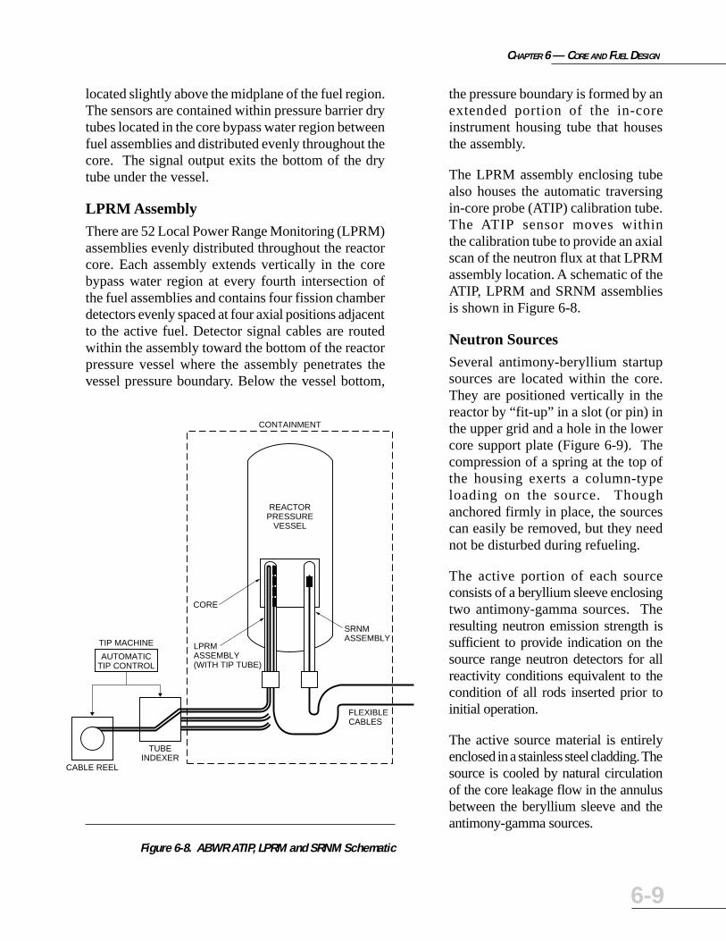
LPRM AssemblyThere are 52 Local Power Range Monitoring (LPRM)assemblies evenly distributed throughout the reactorcore. Each assembly extends vertically in the corebypass water region at every fourth intersection ofthe fuel assemblies and contains four fission chamberdetectors evenly spaced at four axial positions adjacentto the active fuel. Detector signal cables are routedwithin the assembly toward the bottom of the reactorpressure vessel where the assembly penetrates thevessel pressure boundary. Below the vessel bottom,
the pressure boundary is formed by anextended portion of the in-coreinstrument housing tube that housesthe assembly.
The LPRM assembly enclosing tubealso houses the automatic traversingin-core probe (ATIP) calibration tube.The ATIP sensor moves withinthe calibration tube to provide an axialscan of the neutron flux at that LPRMassembly location. A schematic of theATIP, LPRM and SRNM assembliesis shown in Figure 6-8.
Neutron SourcesSeveral antimony-beryllium startupsources are located within the core.They are positioned vertically in thereactor by “fit-up” in a slot (or pin) inthe upper grid and a hole in the lowercore support plate (Figure 6-9). Thecompression of a spring at the top ofthe housing exerts a column-typeloading on the source. Thoughanchored firmly in place, the sourcescan easily be removed, but they neednot be disturbed during refueling.
The active portion of each sourceconsists of a beryllium sleeve enclosingtwo antimony-gamma sources. Theresulting neutron emission strength issufficient to provide indication on thesource range neutron detectors for allreactivity conditions equivalent to thecondition of all rods inserted prior toinitial operation.
The active source material is entirelyenclosed in a stainless steel cladding. Thesource is cooled by natural circulationof the core leakage flow in the annulusbetween the beryllium sleeve and theantimony-gamma sources.
AUTOMATICTIP CONTROL
TIP MACHINE
REACTORPRESSURE
VESSEL
CONTAINMENT
FLEXIBLECABLES
SRNMASSEMBLY
CORE
LPRMASSEMBLY(WITH TIP TUBE)
TUBEINDEXER
CABLE REEL
Figure 6-8. ABWR ATIP, LPRM and SRNM Schematic

CHAPTER 6 — CORE AND FUEL DESIGN
6-10
Core NuclearDesignThe reactor core is designed to operateat rated power without any limitations,while delivering the total cycle lengthand energy desired by the utility.These design goals are achieved by
designing with sufficient margin to thermal andreactivity limits to accommodate the types ofuncertainties encountered in actual operation. Basedon its extensive experience in BWR core design, GEhas developed a consistent set of design margins toensure meeting these objectives without compromisingoverall efficiency due to the use of undueconservatism.
Core ConfigurationThe ABWR core map is illustrated in Figure 6-1. Thereare 872 fuel assemblies, 205 control rods and 52LPRM assemblies. Also the core periphery zone withmore restrictive inlet flow orifices is shown.
Additionally, typical control cell locations are shownin Figure 6-1. ABWR can employ the Control CellCore (CCC) operating strategy in which control rodmovement to offset reactivity changes during poweroperations is limited to a fixed group of control rods.Each of these control rods and its four surroundingfuel assemblies comprise a control cell. All othercontrol rods are normally withdrawn from the corewhile operating at power.
Low reactivity fuel assemblies are placed on the coreperiphery and in the control cells, to reduce neutronleakage and provide for control rod motion adjacentto low power fuel, respectively. For an initial core,the low reactivity fuel is comprised of natural uraniumor low enrichment fuel. For a reload core, the lowreactivity fuel is typically the high exposure fuel; freshand low exposure fuel are scatter loaded in theremaining core fuel assembly locations.
Core Nuclear CharacteristicsReactivity Coefficients: In a boiling water reactor,two reactivity coefficients are of primary importance:the fuel Doppler coefficient and the moderator densityreactivity coefficient. The moderator density reactivitycoefficient may be broken into two components: thatdue to temperature and that due to steam voids.
• Fuel Doppler Reactivity Coefficient: As in alllight water moderated and low enrichmentreactors, the fuel Doppler reactivity coefficient isFigure 6-9. Neutron Source Schematic
TOPGUIDE HOLDER
TIP
SOURCEHOLDER
IRRADIATEDANTIMONY
CAP[SULE (SB-174)
COREMIDPLANE
BERYLLIUM(BE) SLEEVE
COREPLATE

CHAPTER 6 — CORE AND FUEL DESIGN
6-11
negative and prompt in its effect, opposing reactorpower transients. When reactor power increases,the UO
2 temperature increases with minimum time
delay and results in higher neutron absorption byresonance capture in the U-238.
• Moderator Density Reactivity Coefficient:During normal plant operations, the steam voidcomponent of the moderator density reactivitycoefficient is of prime importance. The steam voidcomponent is large and negative at all powerlevels. This steam void effect results in thefollowing operating advantages:
– Xenon Override Capability: Since the steamvoid reactivity effect is large compared withxenon reactivity, the ABWR core has thecapability of overriding the negative reactivityintroduced by the buildup of xenon followinga power decrease.
– Xenon Stability: The steam void reactivityis the primary factor in providing the highresistance to spatial xenon oscillations in aboiling water reactor. Xenon instability is anoscillatory phenomenon of xenonconcentration throughout the reactor that istheoretically possible in any type of reactor.These spatial xenon oscillations give rise tolocal power oscillations which can make itdifficult to maintain the reactor within itsthermal operating limits. Since theseoscillations can be initiated by reactor powerlevel changes, a reactor which is susceptibleto xenon oscillations may be restricted in itsload-following capability. The inherentresistance of the ABWR to xenon instabilitypermits significant flexibility in load-following capability.
– Load Changing by Flow Control: Since thefuel Doppler reactivity opposes a change inload, the void effect must be (and is) largerthan the fuel Doppler effect in order to provideload changing capability by flow (or moderatordensity) control. The ABWR is capable ofdaily load following between 100% and 50%
power by adjusting core flow,with only minor adjustments tothe control rod pattern at lowpower.
Reactivity ControlReactor shutdown control in BWRs isassured through the combined use ofthe control rods and burnable poisonin the fuel. Only a few materials havenuclear cross sections that are suitablefor burnable poisons. An idealburnable poison must be essentiallydepleted in one operating cycle so thatno residual poison exists to penalizethe cycle length. It is also desirablethat the positive reactivity from poisonburnup match the almost lineardecrease in fuel reactivity from fissionproduct buildup and U-235 depletion.A self-shielded burnable poisonconsisting of digadolinia trioxide(Gd
2O
3), called gadolinia, dispersed in
selected fuel rods in each fuelassembly provides the desiredcharacteristics. The gadoliniaconcentration is selected such that thepoison is essentially depleted duringthe operating cycle. Gadolinia hasbeen used in GE BWRs since the early1970s, and has proven to be aneffective and efficient burnable poison.In addition to its use for reactivitycontrol, gadolinia is also used toimprove axial power distributions byaxial zoning of the burnable poisonconcentration.
The core is designed so that adequateshutdown capability is available at alltimes. To permit margin for crediblereactivity changes, the combination ofcontrol rods and burnable poison hasthe capability to shut down the core

CHAPTER 6 — CORE AND FUEL DESIGN
6-12
with the maximum worth control rodfully withdrawn. This capacity isexperimentally demonstrated whenreactivity alternations are made to thereactor core, such as during the initialcore startup, and during each startupafter a refueling outage.
Fuel ManagementThe flexibility of the ABWR coredesign permits significant variation ofthe intervals between refueling. Thefirst shutdown for refueling can occuranywhere from one to two years aftercommencement of initial poweroperation. Thereafter, the cycle lengthcan be varied up to 24 months withGE14 fuel. The desired cycle lengthcan be obtained by adjusting both therefueling batch size and the averageenrichment of the reload bundles.
The average bundle enrichments andbatch sizes are a function of the desiredcycle length. The initial ABWR corehas an average enrichment rangingfrom approximately 1.7 wt% U-235 toapproximately 3.2 wt% U-235 forcycle lengths ranging from one to twoyears. For ABWR reload cores usingGE14 fuel, the average bundleenrichment is roughly 4.2 wt% U-235with a reload batch fraction of 35%for a two year cycle.
NeutronMonitoring System
The Neutron Monitoring System(NMS) is a system of in-core neutrondetectors and out-of-core electronic
monitoring equipment. The system provides indicationof neutron flux, which can be correlated to thermalpower level for the entire range of flux conditions thatcan exist in the core. There are four subsystems in theNMS: the Startup Range Neutron Monitoring (SRNM)Subsystem, the Power Range Neutron Monitoring(PRNM) Subsystem [comprised of the Local PowerRange Monitors (LPRM) and Average Power RangeMonitors (APRM)], the Automatic Traversing In-CoreProbe (ATIP) Subsystem, and the Multi-Channel RodBlock Monitoring (MRBM) Subsystem.
The NMS design has been greatly simplified forABWR application. Key simplification featuresinclude the SRNM, period-based trip logic, andautomation of the Traversing In-core Probe (TIP)System. The SRNMs replace the separate SourceRange Monitor (SRM) and Intermediate RangeMonitor (IRM) found in conventional BWRs. Use ofthese fixed in-core SRNM detectors eliminates thedrive mechanism and the associated control systemsfor the moveable SRM and IRM detectors. IRM rangeswitches have been eliminated by incorporating aperiod-based trip design in the startup power range.Hence, operability is greatly improved and accidentaltrips due to manual range switching are eliminated.TIP System operation for core flux mapping andcalibrating the power range monitors has been fullyautomated in the ABWR design, thereby substantiallyenhancing operability.
Startup Range Neutron Monitoring(SRNM) SubsystemThe SRNM Subsystem monitors the neutron flux fromthe source range to approximately 15% of the rated power.The SRNM Subsystem provides neutron flux related tripinputs (flux level and period) to the Reactor ProtectionSystem (RPS), including a non-coincident trip functionfor refueling operations and a coincident trip functionfor other modes of operation. The SRNM Subsystem has10 channels where each channel includes one detectorinstalled at a fixed position within the core.

CHAPTER 6 — CORE AND FUEL DESIGN
6-13
Power Range Neutron Monitoring(PRNM) SubsystemThe PRNM Subsystem provides flux information formonitoring the average power level of the reactor core.It also provides information for monitoring the localpower level. The PRNM Subsystem monitors localthermal neutron flux up to 125% of rated power, andoverlaps with part of the SRNM range.
The PRNM Subsystem consists of two subsystems:
• Local Power Range Monitoring (LPRM) Subsystem
• Average Power Range Monitoring (APRM) Subsystem
The LPRM Subsystem continuously monitors localcore neutron flux. It consists of 52 detector assemblieswith 4 detectors per assembly. The 208 LPRMdetectors are separated and divided into four groupsto provide four independent APRM signals. TheAPRM Subsystem averages the readings of theassigned LPRM detectors and provides measurementof reactor core power. Individual LPRM signals arealso transmitted through dedicated interface units tovarious systems such as the RCIS, and the plantprocess computer.
An Oscillation Power Range Monitor (OPRM) is alsopart of the APRM. Each OPRM receives identicalLPRM signals from the corresponding APRM asinputs, and forms many OPRM cells to monitor theneutron flux behavior of all regions of the core. TheLPRM signals assigned to each cell are summed andaveraged to provide an OPRM signal for this cell. TheOPRM trip protection algorithm detects thermalhydraulic instability and provides trip output to theRPS if the trip setpoint is exceeded.
Automatic Traversing In-Core Probe (ATIP)SubsystemThis is a single non-safety processor system includedin the NMS used to provide steady state local powerinformation for LPRM calibration and threedimensional reactor power determination.
The ATIP controller contains the purgecontrol system, flux amplifiers andautomatic/manual TIP sequencingcontrols for the three TIP machineslocated in the Reactor Building. TheATIP Subsystem performs an axial scanof the neutron flux in the core at theLPRM assembly locations. Thesubsystem can be controlled manuallyby the operator, or it can be undermicro-processor-based automatedcontrol. The ATIP Subsystem typicallyconsists of neutron-sensitive ionchambers, flexible drive cables, guidetubes, indexing machines, drivemachines, and an automatic controlsystem.
Multi-Channel Rod BlockMonitor (MRBM) SubsystemThe MRBM Subsystem is designed tostop the withdrawal of control rods andprevent fuel damage when the rods areincorrectly being continuouslywithdrawn, whether due tomalfunction or operator error. TheMRBM averages the LPRM signalssurrounding each control rod beingwithdrawn. It compares the averagedLPRM signal to a preset rod blocksetpoint, and, if the averaged valuesexceed this setpoint, the MRBMSubsystem issues a control rod blockdemand to the RCIS. The rod blocksetpoint is a core flow biased variablesetpoint.
Those portions of the NeutronMonitoring System that input signalsto the RPS qualify as a nuclear safetysystem. The SRNM and the APRMSubsystems, which monitor neutronflux via in-core detectors, providescram logic inputs to the RPS to initiate

CHAPTER 6 — CORE AND FUEL DESIGN
6-14
Figure 6-10. Basic Configuration of a Typical NeutronMonitoring System Division
NOTES:
1. DIAGRAM REPRESENTS ONE OF FOUR NMS DIVISIONS (MRBM IS A DUAL CHANNEL SYSTEM.
THERE IS ONLY ONE IN-CORE INSTRUMENT CALIBRATION SYSTEM).
2. USED FOR RAPID CORE FLOW DECREASE TRIP.
3. SRNM AND APRM ATWS PERMISSIVE SIGNALS TO SSLC.
4. INTERCONNECTIONS MAY BE FIBER-OPTIC OR METALLIC.
CORE PLATEDIFFERENTIAL
PRESSURE SENSOR(NOTE 2)
DETECTOR DETECTOR
SRNM PREAMP
SRNM
DETECTOR
LPRM/APRM(INCLUDES OPRM)
RFC
MRBMIN-CORE
INSTRUMENTCALIBRATION
SYSTEM
NMSBOUNDARY
PROCESSCOMPUTER
SYSTEM
(NOTE 3)
SSLC(SLC SYSTEM AND
FEEDWATER RUNBACK)
RCIS(ROD BLOCK)
SSLC(RPS TRIP)
MAINCONTROL
ROOMDISPLAY
RCIS(FLUX)
RFCSYSTEM(FLUX)
SSLC(NBS /ADS)(NOTE 3)
a scram in time to prevent excessivefuel clad damage as a result ofoverpower transients. The APRMSubsystem also generates a simulatedthermal power signal. Both upscaleneutron flux and upscale simulatedthermal power are conditions whichprovide scram logic signals. A blockdiagram of a typical NMS division isshown in Figure 6-10.
Click navigation buttons below to go to
PreviousChapter
NextChapter
Table of Contents