copyright notice: disclaimerasrock.nl/downloadsite/manual/qig/p45x3 deluxe_multiqig.pdf · ... 34...
TRANSCRIPT
11111ASRock P45X3 Deluxe Motherboard
Eng
lish
Eng
lish
Eng
lish
Eng
lish
Eng
lish
Copyright Notice:Copyright Notice:Copyright Notice:Copyright Notice:Copyright Notice:No part of this installation guide may be reproduced, transcribed, transmitted, or trans-lated in any language, in any form or by any means, except duplication of documen-tation by the purchaser for backup purpose, without written consent of ASRock Inc.Products and corporate names appearing in this guide may or may not be registeredtrademarks or copyrights of their respective companies, and are used only for identifica-tion or explanation and to the owners’ benefit, without intent to infringe.
Disclaimer:Disclaimer:Disclaimer:Disclaimer:Disclaimer:Specifications and information contained in this guide are furnished for informationaluse only and subject to change without notice, and should not be constructed as acommitment by ASRock. ASRock assumes no responsibility for any errors or omissionsthat may appear in this guide.With respect to the contents of this guide, ASRock does not provide warranty of any kind,either expressed or implied, including but not limited to the implied warranties orconditions of merchantability or fitness for a particular purpose. In no event shallASRock, its directors, officers, employees, or agents be liable for any indirect, special,incidental, or consequential damages (including damages for loss of profits, loss ofbusiness, loss of data, interruption of business and the like), even if ASRock has beenadvised of the possibility of such damages arising from any defect or error in the guideor product.
This device complies with Part 15 of the FCC Rules. Operation is subject to thefollowing two conditions:(1) this device may not cause harmful interference, and(2) this device must accept any interference received, including interference that
may cause undesired operation.
CALIFORNIA, USA ONLYThe Lithium battery adopted on this motherboard contains Perchlorate, a toxicsubstance controlled in Perchlorate Best Management Practices (BMP) regulationspassed by the California Legislature. When you discard the Lithium battery inCalifornia, USA, please follow the related regulations in advance.“Perchlorate Material-special handling may apply, seewww.dtsc.ca.gov/hazardouswaste/perchlorate”
ASRock Website: http://www.asrock.com
Published May 2009Copyright©2009 ASRock INC. All rights reserved.

22222ASRock P45X3 Deluxe Motherboard
Eng
lishEn
glish
Eng
lishEn
glish
Eng
lish
Motherboard LayoutMotherboard LayoutMotherboard LayoutMotherboard LayoutMotherboard Layout
1 PS2_USB_PWR1 Jumper 21 South Bridge Controller2 ATX 12V Connector (ATX12V1) 22 USB 2.0 Header (USB8_9, Blue)3 775-Pin CPU Socket 23 Debug LED4 North Bridge Controller 24 System Panel Header (PANEL1, Orange)5 CPU Fan Connector (CPU_FAN1) 25 Chassis Speaker Header (SPEAKER 1, Purple)6 2 x 240-pin DDR3 DIMM Slots 26 TPM Header (TPM1)
(Dual Channel A: DDR3_A1, DDR3_B1; Blue) 27 Floppy Connector (FLOPPY1)7 2 x 240-pin DDR3 DIMM Slots 28 COM Port Header (COM1)
(Dual Channel B: DDR3_A2, DDR3_B2; White) 29 Front Panel Audio Header8 ATX Power Connector (ATXPWR1) (HD_AUDIO1, Lime)9 IDE1 Connector (IDE1, Blue) 30 HDMI_SPDIF Header (HDMI_SPDIF1, Yellow)10 Front Panel IEEE 1394 Header 31 Internal Audio Connector: CD1 (Black)
(FRONT_1394; Red) 32 PCI Slots (PCI1- 2)11 Fourth SATAII Connector (SATAII_4; Red) 33 PCI Express x16 Slot (PCIE5; Orange)12 Secondary SATAII Connector (SATAII_2; Red) 34 Infrared Module Header (IR1)13 Chassis Fan Connector (CHA_FAN1) 35 PCI Express x1 Slot (PCIE4)14 Primary SATAII Connector (SATAII_1; Red) 36 SLI/XFire Switch Card Retention Slot15 Third SATAII Connector (SATAII_3; Red) 37 PCI Express x1 Slot (PCIE3)16 Fifth SATAII Connector (SATAII_5; Red) 38 PCI Express x16 Slot (PCIE2; Blue)17 Sixth SATAII Connector (SATAII_6; Red) 39 PCI Express x1 Slot (PCIE1)18 Reset Switch (RSTBTN) 40 Clear CMOS Jumper (CLRCMOS1)19 Power Switch (PWRBTN) 41 Power Fan Connector (PWR_FAN1)20 USB 2.0 Header (USB10_11, Blue) 42 NB Fan Connector (NB_FAN1)
33333ASRock P45X3 Deluxe Motherboard
Eng
lish
Eng
lish
Eng
lish
Eng
lish
Eng
lish
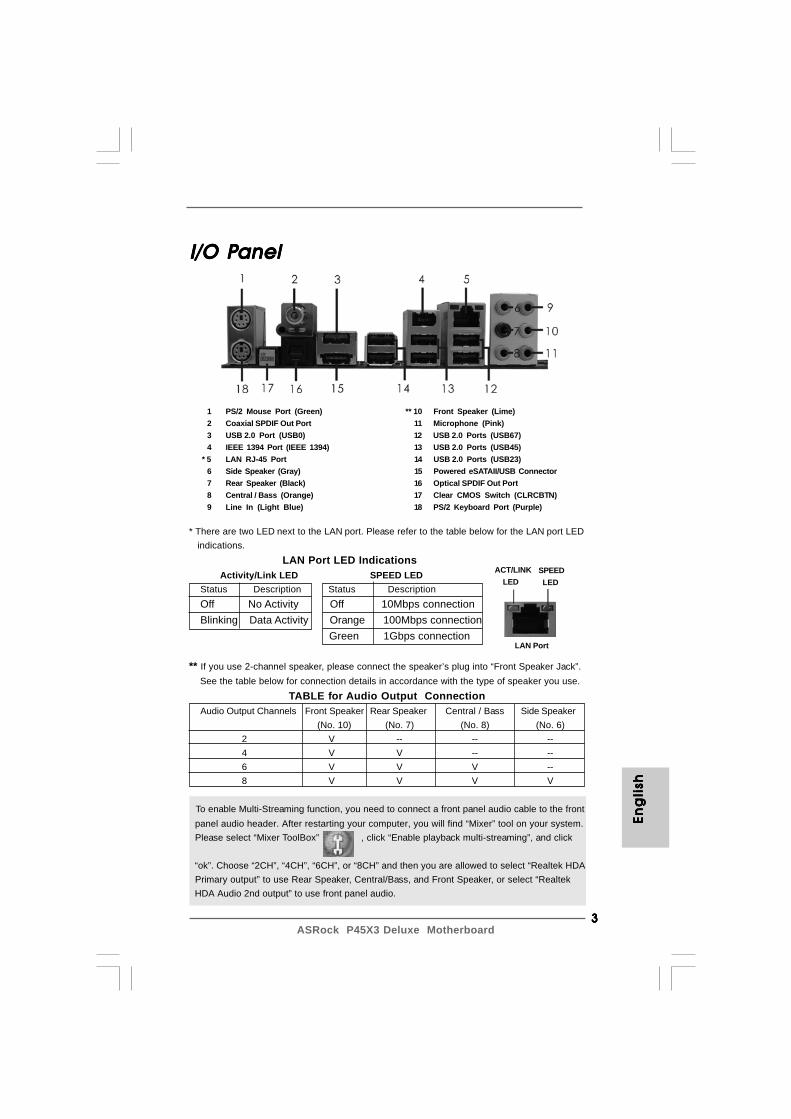
I/O PI/O PI/O PI/O PI/O Panelanelanelanelanel
To enable Multi-Streaming function, you need to connect a front panel audio cable to the front panel audio header. After restarting your computer, you will find “Mixer” tool on your system. Please select “Mixer ToolBox” , click “Enable playback multi-streaming”, and click
“ok”. Choose “2CH”, “4CH”, “6CH”, or “8CH” and then you are allowed to select “Realtek HDA Primary output” to use Rear Speaker, Central/Bass, and Front Speaker, or select “Realtek HDA Audio 2nd output” to use front panel audio.
** If you use 2-channel speaker, please connect the speaker’s plug into “Front Speaker Jack”. See the table below for connection details in accordance with the type of speaker you use.
TABLE for Audio Output ConnectionAudio Output Channels Front Speaker Rear Speaker Central / Bass Side Speaker
(No. 10) (No. 7) (No. 8) (No. 6)2 V -- -- --4 V V -- --6 V V V --8 V V V V
1 PS/2 Mouse Port (Green) ** 10 Front Speaker (Lime)2 Coaxial SPDIF Out Port 11 Microphone (Pink)3 USB 2.0 Port (USB0) 12 USB 2.0 Ports (USB67)4 IEEE 1394 Port (IEEE 1394) 13 USB 2.0 Ports (USB45)
* 5 LAN RJ-45 Port 14 USB 2.0 Ports (USB23)6 Side Speaker (Gray) 15 Powered eSATAII/USB Connector7 Rear Speaker (Black) 16 Optical SPDIF Out Port8 Central / Bass (Orange) 17 Clear CMOS Switch (CLRCBTN)9 Line In (Light Blue) 18 PS/2 Keyboard Port (Purple)
LAN Port
ACT/LINK LED
SPEED LED
* There are two LED next to the LAN port. Please refer to the table below for the LAN port LED indications.
LAN Port LED Indications Activity/Link LED SPEED LEDStatus Description Status DescriptionOff No Activity Off 10Mbps connectionBlinking Data Activity Orange 100Mbps connection
Green 1Gbps connection
44444ASRock P45X3 Deluxe Motherboard
Eng
lishEn
glish
Eng
lishEn
glish
Eng
lish
1. Introduction1. Introduction1. Introduction1. Introduction1. IntroductionThank you for purchasing ASRock P45X3 Deluxe motherboard, a reliable motherboardproduced under ASRock’s consistently stringent quality control. It delivers excellentperformance with robust design conforming to ASRock’s commitment to quality andendurance.This Quick Installation Guide contains introduction of the motherboard and step-by-stepinstallation guide. More detailed information of the motherboard can be found in the usermanual presented in the Support CD.
Because the motherboard specifications and the BIOS software might beupdated, the content of this manual will be subject to change withoutnotice. In case any modifications of this manual occur, the updatedversion will be available on ASRock website without further notice. Youmay find the latest VGA cards and CPU support lists on ASRock websiteas well. ASRock website http://www.asrock.comIf you require technical support related to this motherboard, please visitour website for specific information about the model you are using.www.asrock.com/support/index.asp
1.1 Package Contents1.1 Package Contents1.1 Package Contents1.1 Package Contents1.1 Package ContentsASRock P45X3 Deluxe Motherboard
(ATX Form Factor: 12.0-in x 9.6-in, 30.5 cm x 24.4 cm)ASRock P45X3 Deluxe Quick Installation GuideASRock P45X3 Deluxe Support CDOne ASRock SLI/XFire Switch CardOne 80-conductor Ultra ATA 66/100/133 IDE Ribbon CableOne Ribbon Cable for a 3.5-in Floppy DriveFour Serial ATA (SATA) Data Cables (Optional)One Serial ATA (SATA) HDD Power Cable (Optional)One I/O Panel Shield
55555ASRock P45X3 Deluxe Motherboard
Eng
lish
Eng
lish
Eng
lish
Eng
lish
Eng
lish
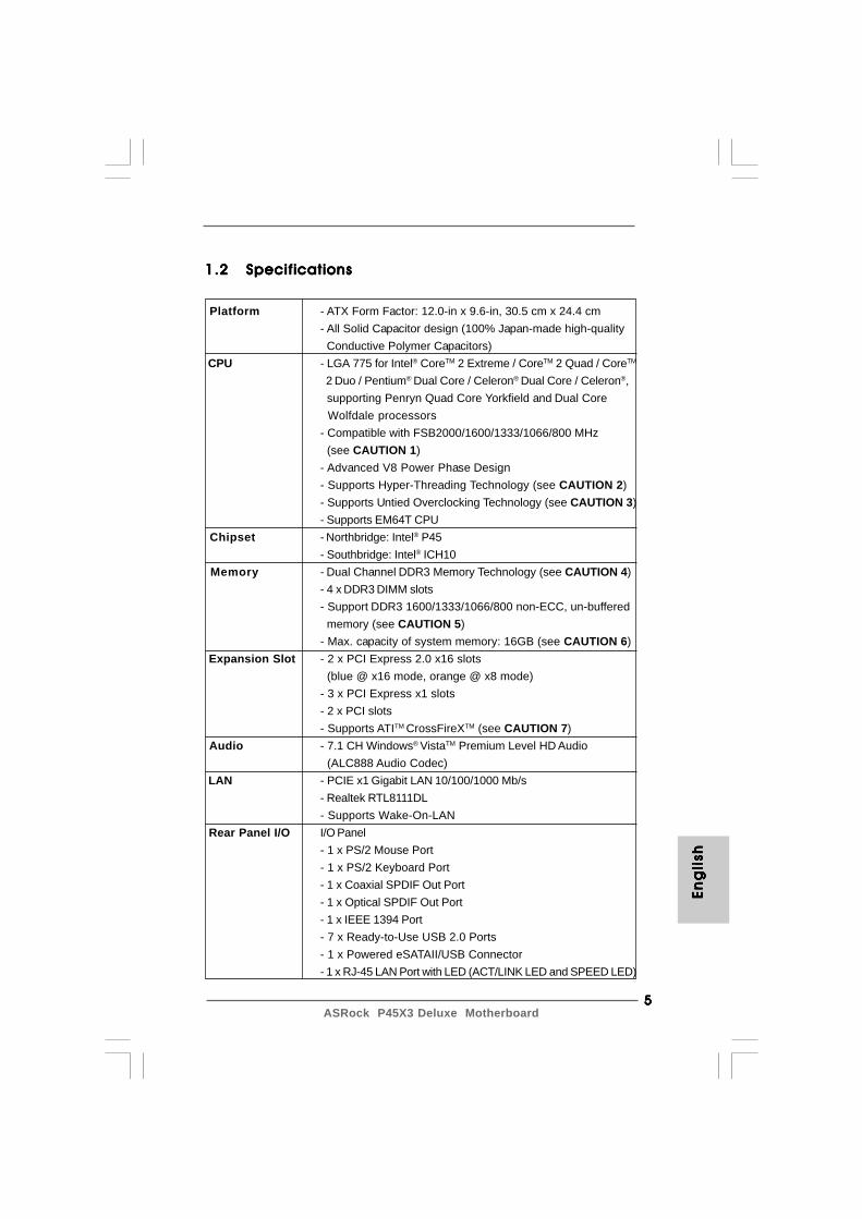
1.21.21.21.21.2 SpecificationsSpecificationsSpecificationsSpecificationsSpecifications
Platform - ATX Form Factor: 12.0-in x 9.6-in, 30.5 cm x 24.4 cm- All Solid Capacitor design (100% Japan-made high-quality Conductive Polymer Capacitors)
CPU - LGA 775 for Intel® CoreTM 2 Extreme / CoreTM 2 Quad / CoreTM
2 Duo / Pentium® Dual Core / Celeron® Dual Core / Celeron®, supporting Penryn Quad Core Yorkfield and Dual Core Wolfdale processors- Compatible with FSB2000/1600/1333/1066/800 MHz (see CAUTION 1)- Advanced V8 Power Phase Design- Supports Hyper-Threading Technology (see CAUTION 2)- Supports Untied Overclocking Technology (see CAUTION 3)- Supports EM64T CPU
Chipset - Northbridge: Intel® P45- Southbridge: Intel® ICH10
Memory - Dual Channel DDR3 Memory Technology (see CAUTION 4)- 4 x DDR3 DIMM slots- Support DDR3 1600/1333/1066/800 non-ECC, un-buffered memory (see CAUTION 5)- Max. capacity of system memory: 16GB (see CAUTION 6)
Expansion Slot - 2 x PCI Express 2.0 x16 slots (blue @ x16 mode, orange @ x8 mode)- 3 x PCI Express x1 slots- 2 x PCI slots- Supports ATITM CrossFireXTM (see CAUTION 7)
Audio - 7.1 CH Windows® VistaTM Premium Level HD Audio (ALC888 Audio Codec)
LAN - PCIE x1 Gigabit LAN 10/100/1000 Mb/s- Realtek RTL8111DL- Supports Wake-On-LAN
Rear Panel I/O I/O Panel- 1 x PS/2 Mouse Port- 1 x PS/2 Keyboard Port- 1 x Coaxial SPDIF Out Port- 1 x Optical SPDIF Out Port- 1 x IEEE 1394 Port- 7 x Ready-to-Use USB 2.0 Ports- 1 x Powered eSATAII/USB Connector- 1 x RJ-45 LAN Port with LED (ACT/LINK LED and SPEED LED)
66666ASRock P45X3 Deluxe Motherboard
Eng
lishEn
glish
Eng
lishEn
glish
Eng
lish
- 1 x Clear CMOS Switch with LED- HD Audio Jack: Side Speaker/Rear Speaker/Central/Bass/ Line in/Front Speaker/Microphone (see CAUTION 8)
Connector - 6 x SATAII 3.0Gb/s connectors, support NCQ, AHCI and “Hot Plug” functions (see CAUTION 9)- 1 x ATA133 IDE connector (supports 2 x IDE devices)- 1 x Floppy connector- 1 x IR header- 1 x COM port header- 1 x HDMI_SPDIF header- 1 x IEEE 1394 header- 1 x TPM header- CPU/Chassis/NB/Power FAN connector- 24 pin ATX power connector- 8 pin 12V power connector- CD in header- Front panel audio connector- 2 x USB 2.0 headers (support 4 USB 2.0 ports) (see CAUTION 10)
Quick Switch - 1 x Clear CMOS Switch with LED- 1 x Power Switch with LED- 1 x Reset Switch with LED
BIOS Feature - 8Mb AMI BIOS- AMI Legal BIOS- Supports “Plug and Play”- ACPI 1.1 Compliance Wake Up Events- Supports jumperfree- AMBIOS 2.3.1 Support- CPU, VCCM, VTT Voltage Multi-adjustment- Supports I. O. T. (Intelligent Overclocking Technology)- Supports Smart BIOS
Support CD - Drivers, Utilities, AntiVirus Software (Trial Version) Unique Feature - ASRock OC Tuner (see CAUTION 11)
- Intelligent Energy Saver (see CAUTION 12)- Instant Boot- ASRock Instant Flash (see CAUTION 13)- Hybrid Booster:
- CPU Frequency Stepless Control (see CAUTION 14)- ASRock U-COP (see CAUTION 15)- Boot Failure Guard (B.F.G.)
Hardware - CPU Temperature Sensing Monitor - Chassis Temperature Sensing
77777ASRock P45X3 Deluxe Motherboard
Eng
lish
Eng
lish
Eng
lish
Eng
lish
Eng
lish
WARNINGPlease realize that there is a certain risk involved with overclocking, including adjustingthe setting in the BIOS, applying Untied Overclocking Technology, or using the third-party overclocking tools. Overclocking may affect your system stability, or evencause damage to the components and devices of your system. It should be done atyour own risk and expense. We are not responsible for possible damage caused byoverclocking.
CAUTION!1. Some CPU you adopt may be overclocked to FSB2000 MHz, in this
situation, please adopt DDR3 1333 or DDR3 1600 memory modules onthis motherboard.
2. About the setting of “Hyper Threading Technology”, please check page 49of “User Manual” in the support CD.
3. This motherboard supports Untied Overclocking Technology. Please read“Untied Overclocking Technology” on page 32 for details.
4. This motherboard supports Dual Channel Memory Technology. Before youimplement Dual Channel Memory Technology, make sure to read theinstallation guide of memory modules on page 12 for proper installation.
5. Please check the table below for the CPU FSB frequency and itscorresponding memory support frequency.
CPU FSB Frequency Memory Support Frequency1600 DDR3 800, DDR3 1066, DDR3 1333,
DDR3 16001333 DDR3 800, DDR3 1066, DDR3 13331066 DDR3 800, DDR3 1066800 DDR3 800
* DDR3 1600 memory module is operating in overclocking mode.6. Due to the operating system limitation, the actual memory size may be
less than 4GB for the reservation for system usage under Windows® XPand Windows® VistaTM. For Windows® XP 64-bit and Windows® VistaTM 64-bit with 64-bit CPU, there is no such limitation.
7. This motherboard supports ATITM CrossFireXTM technology. If you want to useCrossFireXTM function, please follow the instructions on page 17 to reverse thedirection of ASRock SLI/XFire Switch Card in advance.
- CPU/Chassis/NB/Power Fan Tachometer- CPU Quiet Fan- Voltage Monitoring: +12V, +5V, +3.3V, CPU Vcore
OS - Microsoft® Windows® 2000 / XP / XP 64-bit / VistaTM / VistaTM 64-bit compliant (see CAUTION 16)
Certifications - FCC, CE, WHQL * For detailed product information, please visit our website: http://www.asrock.com
88888ASRock P45X3 Deluxe Motherboard
Eng
lishEn
glish
Eng
lishEn
glish
Eng
lish
8. For microphone input, this motherboard supports both stereo and monomodes. For audio output, this motherboard supports 2-channel, 4-channel,6-channel, and 8-channel modes. Please check the table on page 3 forproper connection.
9. Before installing SATAII hard disk to SATAII connector, please read the“SATAII Hard Disk Setup Guide” on page 37 of “User Manual” in the supportCD to adjust your SATAII hard disk drive to SATAII mode. You can alsoconnect SATA hard disk to SATAII connector directly.
10. Power Management for USB 2.0 works fine under Microsoft® Windows®
VistaTM 64-bit / VistaTM / XP 64-bit / XP SP1 or SP2 / 2000 SP4.11. It is a user-friendly ASRock overclocking tool which allows you to surveil
your system by hardware monitor function and overclock your hardwaredevices to get the best system performance under Windows® environment.Please visit our website for the operation procedures of ASRock OCTuner. ASRock website: http://www.asrock.com
12. Featuring an advanced proprietary hardware and software design,Intelligent Energy Saver is a revolutionary technology that deliversunparalleled power savings. In other words, it is able to provide exceptionalpower saving and improve power efficiency without sacrificing computingperformance. Please visit our website for the operation procedures ofIntelligent Energy Saver.ASRock website: http://www.asrock.com
13. ASRock Instant Flash is a BIOS flash utility embedded in Flash ROM.This convenient BIOS update tool allows you to update system BIOSwithout entering operating systems first like MS-DOS or Windows®. Withthis utility, you can press <F6> key during the POST or press <F2> key toBIOS setup menu to access ASRock Instant Flash. Just launch this tooland save the new BIOS file to your USB flash drive, floppy disk or harddrive, then you can update your BIOS only in a few clicks without prepar-ing an additional floppy diskette or other complicated flash utility. Pleasebe noted that the USB flash drive or hard drive must use FAT32/16/12 filesystem.
14. Although this motherboard offers stepless control, it is not recommendedto perform over-clocking. Frequencies other than the recommended CPUbus frequencies may cause the instability of the system or damage theCPU.
15. While CPU overheat is detected, the system will automatically shutdown.Before you resume the system, please check if the CPU fan on themotherboard functions properly and unplug the power cord, then plug itback again. To improve heat dissipation, remember to spray thermalgrease between the CPU and the heatsink when you install the PC system.
16. AHCI function is not supported under Windows® 2000 OS. It is recom-mended to use IDE mode under Windows® 2000. Please refer to page 59 of“User Manual” in the support CD for detailed setup.
99999ASRock P45X3 Deluxe Motherboard
2.2.2.2.2. InstallationInstallationInstallationInstallationInstallation
Pre-installation PrecautionsPre-installation PrecautionsPre-installation PrecautionsPre-installation PrecautionsPre-installation PrecautionsTake note of the following precautions before you install mother-board components or change any motherboard settings.
1. Unplug the power cord from the wall socket before touching anycomponent. Failure to do so may cause severe damage to themotherboard, peripherals, and/or components.
2. To avoid damaging the motherboard components due to staticelectricity, NEVER place your motherboard directly on the carpetor the like. Also remember to use a grounded wrist strap or toucha safety grounded object before you handle components.
3. Hold components by the edges and do not touch the ICs.4. Whenever you uninstall any component, place it on a grounded
antstatic pad or in the bag that comes with the component.5. When placing screws into the screw holes to secure the
motherboard to the chassis, please do not over-tighten thescrews! Doing so may damage the motherboard.
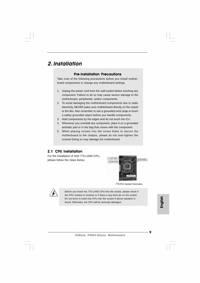
2.12.12.12.12.1 CPU InstallationCPU InstallationCPU InstallationCPU InstallationCPU InstallationFor the installation of Intel 775-LAND CPU,please follow the steps below.
Before you insert the 775-LAND CPU into the socket, please check ifthe CPU surface is unclean or if there is any bent pin on the socket.Do not force to insert the CPU into the socket if above situation isfound. Otherwise, the CPU will be seriously damaged.
775-Pin Socket Overview
Eng
lish
Eng
lish
Eng
lish
Eng
lish
Eng
lish
1 01 01 01 01 0ASRock P45X3 Deluxe Motherboard
Eng
lishEn
glish
Eng
lishEn
glish
Eng
lish
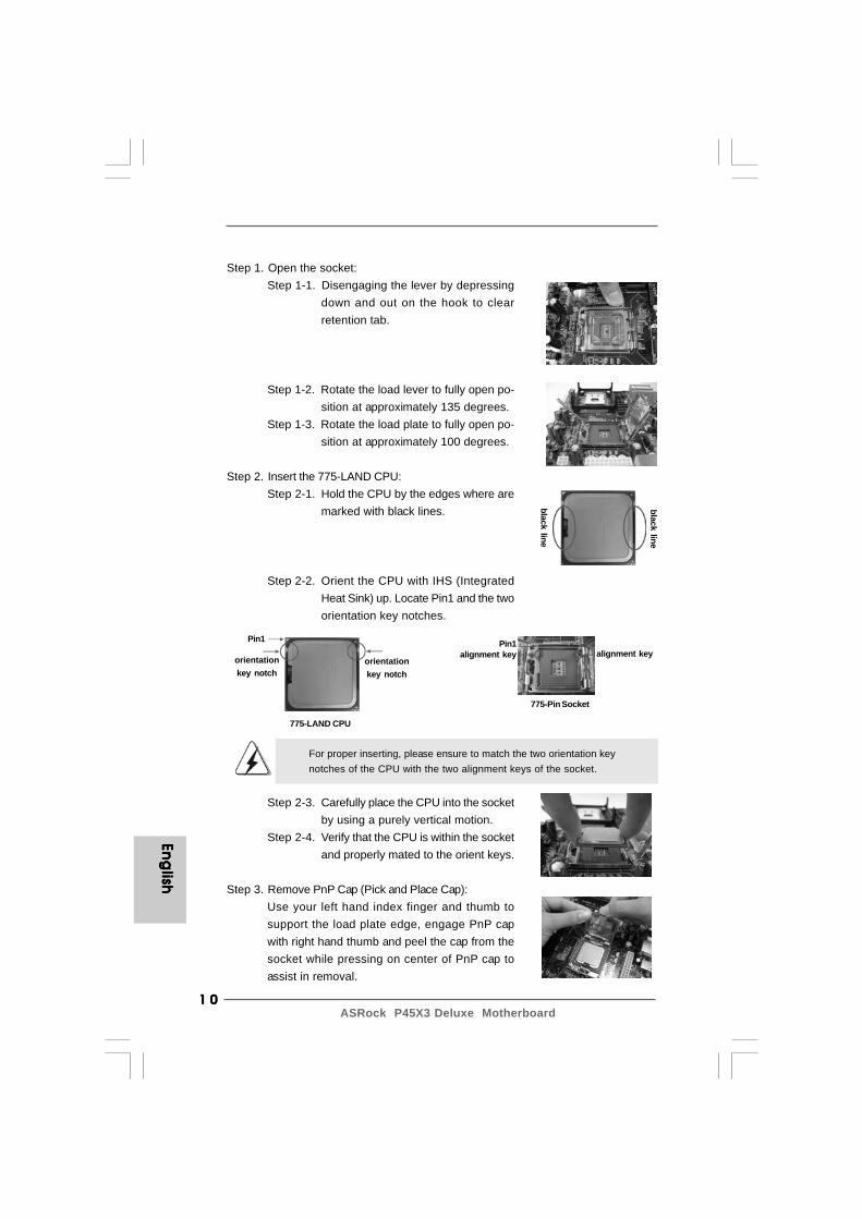
Step 1. Open the socket:Step 1-1. Disengaging the lever by depressing
down and out on the hook to clearretention tab.
Step 1-2. Rotate the load lever to fully open po-sition at approximately 135 degrees.
Step 1-3. Rotate the load plate to fully open po-sition at approximately 100 degrees.
Step 2. Insert the 775-LAND CPU:Step 2-1. Hold the CPU by the edges where are
marked with black lines.
Step 2-2. Orient the CPU with IHS (IntegratedHeat Sink) up. Locate Pin1 and the twoorientation key notches.
For proper inserting, please ensure to match the two orientation keynotches of the CPU with the two alignment keys of the socket.
Step 2-3. Carefully place the CPU into the socketby using a purely vertical motion.
Step 2-4. Verify that the CPU is within the socketand properly mated to the orient keys.
Step 3. Remove PnP Cap (Pick and Place Cap):Use your left hand index finger and thumb tosupport the load plate edge, engage PnP capwith right hand thumb and peel the cap from thesocket while pressing on center of PnP cap toassist in removal.
black line
black line
775-Pin Socket
Pin1alignment key alignment key
Pin1
orientationkey notch
orientationkey notch
775-LAND CPU
1 11 11 11 11 1ASRock P45X3 Deluxe Motherboard
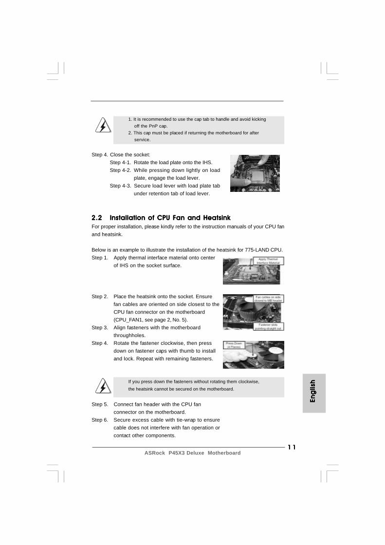
1. It is recommended to use the cap tab to handle and avoid kicking off the PnP cap.2. This cap must be placed if returning the motherboard for after service.
Step 4. Close the socket:Step 4-1. Rotate the load plate onto the IHS.Step 4-2. While pressing down lightly on load
plate, engage the load lever.Step 4-3. Secure load lever with load plate tab
under retention tab of load lever.
2.22.22.22.22.2 Installation of CPU Fan and HeatsinkInstallation of CPU Fan and HeatsinkInstallation of CPU Fan and HeatsinkInstallation of CPU Fan and HeatsinkInstallation of CPU Fan and HeatsinkFor proper installation, please kindly refer to the instruction manuals of your CPU fanand heatsink.
Below is an example to illustrate the installation of the heatsink for 775-LAND CPU.Step 1. Apply thermal interface material onto center
of IHS on the socket surface.
Step 2. Place the heatsink onto the socket. Ensurefan cables are oriented on side closest to theCPU fan connector on the motherboard(CPU_FAN1, see page 2, No. 5).
Step 3. Align fasteners with the motherboardthroughholes.
Step 4. Rotate the fastener clockwise, then pressdown on fastener caps with thumb to installand lock. Repeat with remaining fasteners.
If you press down the fasteners without rotating them clockwise,the heatsink cannot be secured on the motherboard.
Step 5. Connect fan header with the CPU fanconnector on the motherboard.
Step 6. Secure excess cable with tie-wrap to ensurecable does not interfere with fan operation orcontact other components.
Eng
lish
Eng
lish
Eng
lish
Eng
lish
Eng
lish
1 21 21 21 21 2ASRock P45X3 Deluxe Motherboard
Eng
lishEn
glish
Eng
lishEn
glish
Eng
lish
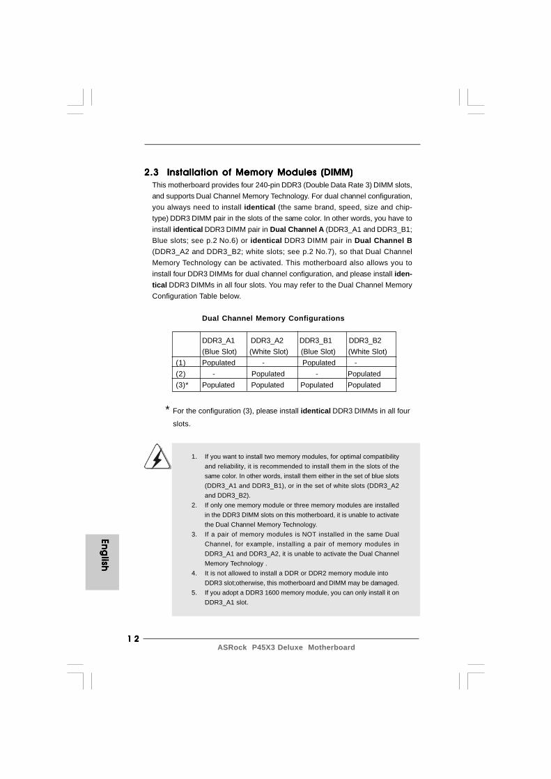
2.3 Installation of Memory Modules (DIMM)2.3 Installation of Memory Modules (DIMM)2.3 Installation of Memory Modules (DIMM)2.3 Installation of Memory Modules (DIMM)2.3 Installation of Memory Modules (DIMM)This motherboard provides four 240-pin DDR3 (Double Data Rate 3) DIMM slots,and supports Dual Channel Memory Technology. For dual channel configuration,you always need to install identical (the same brand, speed, size and chip-type) DDR3 DIMM pair in the slots of the same color. In other words, you have toinstall identical DDR3 DIMM pair in Dual Channel A (DDR3_A1 and DDR3_B1;Blue slots; see p.2 No.6) or identical DDR3 DIMM pair in Dual Channel B(DDR3_A2 and DDR3_B2; white slots; see p.2 No.7), so that Dual ChannelMemory Technology can be activated. This motherboard also allows you toinstall four DDR3 DIMMs for dual channel configuration, and please install iden-tical DDR3 DIMMs in all four slots. You may refer to the Dual Channel MemoryConfiguration Table below.
Dual Channel Memory Configurations
DDR3_A1 DDR3_A2 DDR3_B1 DDR3_B2(Blue Slot) (White Slot) (Blue Slot) (White Slot)
(1) Populated - Populated -(2) - Populated - Populated(3)* Populated Populated Populated Populated
* For the configuration (3), please install identical DDR3 DIMMs in all four
slots.
1. If you want to install two memory modules, for optimal compatibilityand reliability, it is recommended to install them in the slots of thesame color. In other words, install them either in the set of blue slots(DDR3_A1 and DDR3_B1), or in the set of white slots (DDR3_A2and DDR3_B2).
2. If only one memory module or three memory modules are installedin the DDR3 DIMM slots on this motherboard, it is unable to activatethe Dual Channel Memory Technology.
3. If a pair of memory modules is NOT installed in the same DualChannel, for example, installing a pair of memory modules inDDR3_A1 and DDR3_A2, it is unable to activate the Dual ChannelMemory Technology .
4. It is not allowed to install a DDR or DDR2 memory module intoDDR3 slot;otherwise, this motherboard and DIMM may be damaged.
5. If you adopt a DDR3 1600 memory module, you can only install it onDDR3_A1 slot.
1 31 31 31 31 3ASRock P45X3 Deluxe Motherboard
Eng
lish
Eng
lish
Eng
lish
Eng
lish
Eng
lish
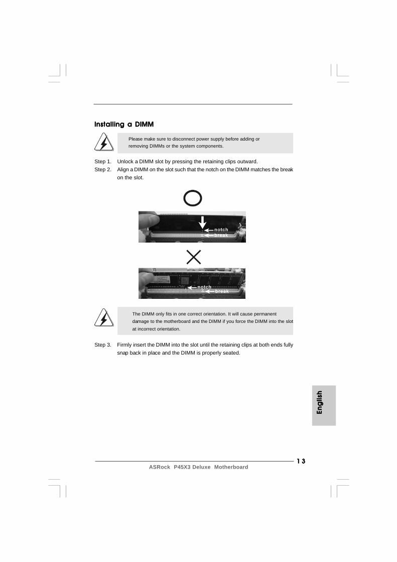
Installing a DIMMInstalling a DIMMInstalling a DIMMInstalling a DIMMInstalling a DIMM
Please make sure to disconnect power supply before adding orremoving DIMMs or the system components.
Step 1. Unlock a DIMM slot by pressing the retaining clips outward.Step 2. Align a DIMM on the slot such that the notch on the DIMM matches the break
on the slot.
The DIMM only fits in one correct orientation. It will cause permanentdamage to the motherboard and the DIMM if you force the DIMM into the slotat incorrect orientation.
Step 3. Firmly insert the DIMM into the slot until the retaining clips at both ends fullysnap back in place and the DIMM is properly seated.
1 41 41 41 41 4ASRock P45X3 Deluxe Motherboard
Eng
lishEn
glish
Eng
lishEn
glish
Eng
lish
2.4 Expansion Slots (PCI and PCI Express Slots)2.4 Expansion Slots (PCI and PCI Express Slots)2.4 Expansion Slots (PCI and PCI Express Slots)2.4 Expansion Slots (PCI and PCI Express Slots)2.4 Expansion Slots (PCI and PCI Express Slots)There are 2 PCI slots and 5 PCI Express slots on this motherboard.PCI Slots: PCI slots are used to install expansion cards that have the 32-bit PCI
interface.PCIE Slots:
PCIE1 / PCIE3 / PCIE4 (PCIE x1 slot; White) is used for PCI Expresscards with x1 lane width cards, such as Gigabit LAN card, SATA2card, etc.PCIE2 (PCIE x16 slot; Blue) is used for PCI Express x16 lane widthgraphics cards, or used to install PCI Express graphics cards tosupport CrossFireXTM function.PCIE5 (PCIE x16 slot; Orange) is used for PCI Express x1 lane widthcards, such as Gigabit LAN card, SATA2 card, etc., or used to installPCI Express graphics cards to support CrossFireXTM function.
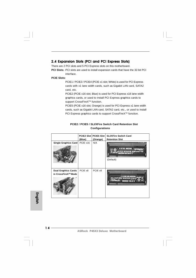
PCIE2 / PCIE5 / SLI/XFire Switch Card Retention Slot Configurations
PCIE2 Slot PCIE5 Slot SLI/XFire Switch Card (Blue) (Orange) Retention Slot
Single Graphics Card PCIE x16 N/A
Dual Graphics Cards PCIE x8 PCIE x8 in CrossFireXTM Mode
(Default)
1 51 51 51 51 5ASRock P45X3 Deluxe Motherboard
Eng
lish
Eng
lish
Eng
lish
Eng
lish
Eng
lish
1. If you plan to install only one PCI Express VGA card on this motherboard, please install it on PCIE2 slot (Blue). In this mode, you do not need to adjust the default setting of ASRock SLI/XFire Switch Card, and please do not remove or lose ASRock SLI/XFire Switch Card when it is still in working condition.2. For the information of the compatible CrossFireXTM Mode PCI Express VGA cards and CrossFireXTM setup procedures, please refer to “CrossFireXTM Operation Guide” on page 16.
Installing an expansion cardInstalling an expansion cardInstalling an expansion cardInstalling an expansion cardInstalling an expansion cardStep 1. Before installing the expansion card, please make sure that the power
supply is switched off or the power cord is unplugged. Please read thedocumentation of the expansion card and make necessary hardwaresettings for the card before you start the installation.
Step 2. Remove the system unit cover (if your motherboard is already installed ina chassis).
Step 3. Remove the bracket facing the slot that you intend to use. Keep thescrews for later use.
Step 4. Align the card connector with the slot and press firmly until the card iscompletely seated on the slot.
Step 5. Fasten the card to the chassis with screws.Step 6. Replace the system cover.
1 61 61 61 61 6ASRock P45X3 Deluxe Motherboard
2.5 CrossFireX2.5 CrossFireX2.5 CrossFireX2.5 CrossFireX2.5 CrossFireXTMTMTMTMTM Operation Guide Operation Guide Operation Guide Operation Guide Operation GuideThis motherboard supports CrossFireXTM feature. CrossFireXTM technology offersthe most advantageous means available of combining multiple high performanceGraphics Processing Units (GPU) in a single PC. Combining a range of differentoperating modes with intelligent software design and an innovative interconnectmechanism, CrossFireXTM enables the highest possible level of performance andimage quality in any 3D application. Currently CrossFireXTM feature is supported withWindows® XP with Service Pack 2 and VistaTM OS. Please check AMD website forATITM CrossFireXTM driver updates.
Eng
lishEn
glish
Eng
lishEn
glish
Eng
lish
1. If a customer incorrectly configures their system they will not see the performance benefits of CrossFireXTM. All three CrossFireXTM components, a CrossFireXTM Ready graphics card, a CrossFireXTM Ready motherboard and a CrossFireXTM Edition co-processor graphics card, must be installed correctly to benefit from the CrossFireXTM multi-GPU platform.2. If you pair a 12-pipe CrossFireXTM Edition card with a 16-pipe card, both cards will operate as 12-pipe cards while in CrossFireXTM mode.
What graphics cards work with CrossFireXTM?A complete CrossFireXTM system requires a CrossFireXTM Ready motherboard, aCrossFireXTM Edition graphics card and a compatible standard Radeon (CrossFireXTM
Ready) graphics card from the same series, or two CrossFireXTM Ready cards. Thisapplies to cards from ATITM or any of its partners. Please refer to below table forCrossFireXTM VGA card support list according to the OS you install.
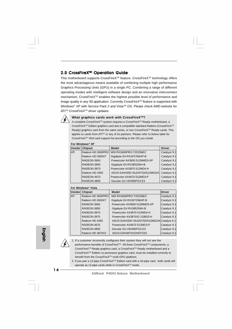
For Windows® XPVendor Chipset Model DriverATI Radeon HD 2600PRO MSI RX2600PRO-T2D256EZ Catalyst 9.1
Radeon HD 2600XT Gigabyte GV-RX26T256HP-B Catalyst 9.1RADEON 3650 Powercolor AX3650 512MMD3-XP Catalyst 9.1RADEON 3850 Gigabyte GV-RX385256H-B Catalyst 9.1RADEON 3870 Powercolor AX3870 512MD4-H Catalyst 9.1Radeon HD 4350 ASUS EAH4350 SILENT/DI/512MD2/A Catalyst 9.1RADEON 4670 Powercolor AX4670 512MD3-P Catalyst 9.1RADEON 4850 Gecube GC-HD485PG3-E3 Catalyst 9.1
For Windows® VistaVendor Chipset Model DriverATI Radeon HD 2600PRO MSI RX2600PRO-T2D256EZ Catalyst 9.1
Radeon HD 2600XT Gigabyte GV-RX26T256HP-B Catalyst 9.1RADEON 3650 Powercolor AX3650 512MMD3-XP Catalyst 9.1RADEON 3850 Gigabyte GV-RX385256H-B Catalyst 9.1RADEON 3870 Powercolor AX3870 512MD4-H Catalyst 9.1RADEON 3870 Powercolor AX3870X2 1GBD3-H Catalyst 9.1Radeon HD 4350 ASUS EAH4350 SILENT/DI/512MD2/A Catalyst 9.1RADEON 4670 Powercolor AX4670 512MD3-P Catalyst 9.1RADEON 4850 Gecube GC-HD485PG3-E3 Catalyst 9.1Radeon HD 4870X2 ASUS EAH4870X2/HDTI/2G Catalyst 9.1
1 71 71 71 71 7ASRock P45X3 Deluxe Motherboard
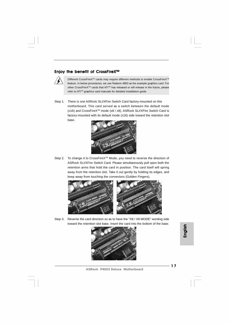
Step 1. There is one ASRock SLI/XFire Switch Card factory-mounted on thismotherboard. This card served as a switch between the default mode(x16) and CrossFireXTM mode (x8 / x8). ASRock SLI/XFire Switch Card isfactory-mounted with its default mode (x16) side toward the retention slotbase.
Step 2. To change it to CrossFireXTM Mode, you need to reverse the direction ofASRock SLI/XFire Switch Card. Please simultaneously pull open both theretention arms that hold the card in position. The card itself will springaway from the retention slot. Take it out gently by holding its edges, andkeep away from touching the connectors (Golden Fingers).
Step 3. Reverse the card direction so as to have the “X8 / X8 MODE” wording sidetoward the retention slot base. Insert the card into the bottom of the base.
Enjoy the benefit of CrossFireXEnjoy the benefit of CrossFireXEnjoy the benefit of CrossFireXEnjoy the benefit of CrossFireXEnjoy the benefit of CrossFireXTMTMTMTMTM
Different CrossFireXTM cards may require different methods to enable CrossFireXTM
feature. In below procedures, we use Radeon 4850 as the example graphics card. Forother CrossFireXTM cards that ATITM has released or will release in the future, pleaserefer to ATITM graphics card manuals for detailed installation guide.
Eng
lish
Eng
lish
Eng
lish
Eng
lish
Eng
lish
1 81 81 81 81 8ASRock P45X3 Deluxe Motherboard
Eng
lishEn
glish
Eng
lishEn
glish
Eng
lish
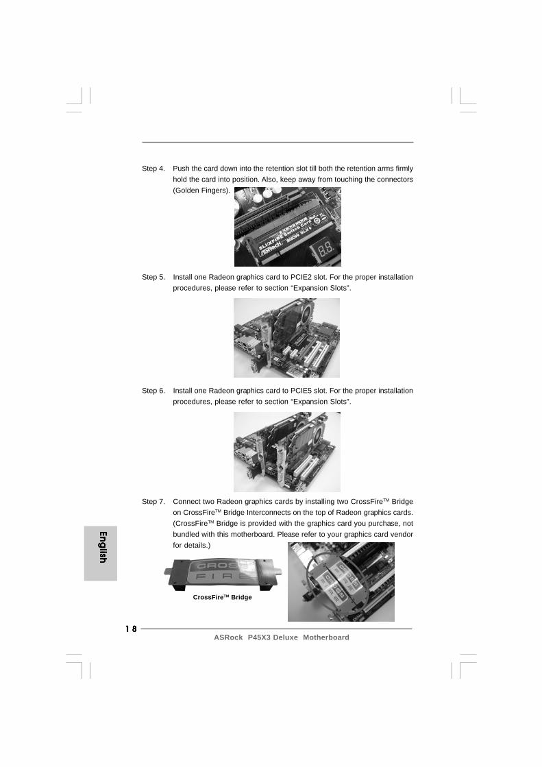
Step 5. Install one Radeon graphics card to PCIE2 slot. For the proper installationprocedures, please refer to section “Expansion Slots”.
Step 6. Install one Radeon graphics card to PCIE5 slot. For the proper installationprocedures, please refer to section “Expansion Slots”.
Step 7. Connect two Radeon graphics cards by installing two CrossFireTM Bridgeon CrossFireTM Bridge Interconnects on the top of Radeon graphics cards.(CrossFireTM Bridge is provided with the graphics card you purchase, notbundled with this motherboard. Please refer to your graphics card vendorfor details.)
CrossFireTM Bridge
Step 4. Push the card down into the retention slot till both the retention arms firmlyhold the card into position. Also, keep away from touching the connectors(Golden Fingers).
1 91 91 91 91 9ASRock P45X3 Deluxe Motherboard
Eng
lish
Eng
lish
Eng
lish
Eng
lish
Eng
lish
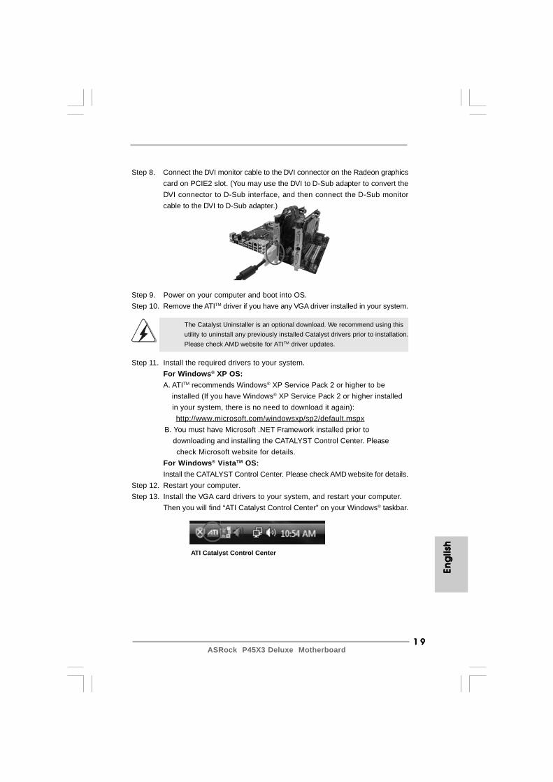
Step 9. Power on your computer and boot into OS.Step 10. Remove the ATITM driver if you have any VGA driver installed in your system.
The Catalyst Uninstaller is an optional download. We recommend using thisutility to uninstall any previously installed Catalyst drivers prior to installation.Please check AMD website for ATITM driver updates.
Step 11. Install the required drivers to your system.For Windows® XP OS:A. ATITM recommends Windows® XP Service Pack 2 or higher to be installed (If you have Windows® XP Service Pack 2 or higher installed in your system, there is no need to download it again):
http://www.microsoft.com/windowsxp/sp2/default.mspx B. You must have Microsoft .NET Framework installed prior to downloading and installing the CATALYST Control Center. Please check Microsoft website for details.
For Windows® VistaTM OS:Install the CATALYST Control Center. Please check AMD website for details.
Step 12. Restart your computer.Step 13. Install the VGA card drivers to your system, and restart your computer.
Then you will find “ATI Catalyst Control Center” on your Windows® taskbar.
ATI Catalyst Control Center
Step 8. Connect the DVI monitor cable to the DVI connector on the Radeon graphicscard on PCIE2 slot. (You may use the DVI to D-Sub adapter to convert theDVI connector to D-Sub interface, and then connect the D-Sub monitorcable to the DVI to D-Sub adapter.)
2 02 02 02 02 0ASRock P45X3 Deluxe Motherboard
Eng
lishEn
glish
Eng
lishEn
glish
Eng
lish
Although you have selected the option “Enable CrossFireTM”, the CrossFireXTM
function may not work actually. Your computer will automatically reboot. Afterrestarting your computer, please confirm whether the option “Enable CrossFireTM”in “ATI Catalyst Control Center” is selected or not; if not, please select it again,and then you are able to enjoy the benefit of CrossFireXTM feature.
Step 15. You can freely enjoy the benefit of CrossFireXTM feature.
* CrossFireXTM appearing here is a registered trademark of ATITM Technologies Inc., and is used only for identification or explanation and to the owners’ benefit, without intent to infringe.* For further information of ATITM CrossFireXTM technology, please check AMD website for updates and details.
2.6 Surround Display Feature2.6 Surround Display Feature2.6 Surround Display Feature2.6 Surround Display Feature2.6 Surround Display FeatureThis motherboard supports Surround Display upgrade. With the external add-onPCI Express VGA cards, you can easily enjoy the benefits of Surround Displayfeature. For the detailed instruction, please refer to the document at the followingpath in the Support CD:..\ Surround Display Information
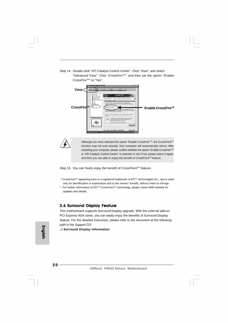
Step 14. Double-click “ATI Catalyst Control Center”. Click “View”, and select“Advanced View”. Click “CrossFireTM”, and then set the option “EnableCrossFireTM” to “Yes”.
View
CrossFireTM Enable CrossFireTM

2 12 12 12 12 1ASRock P45X3 Deluxe Motherboard
2.7 Jumpers Setup2.7 Jumpers Setup2.7 Jumpers Setup2.7 Jumpers Setup2.7 Jumpers SetupThe illustration shows how jumpers aresetup. When the jumper cap is placed onpins, the jumper is “Short”. If no jumper capis placed on pins, the jumper is “Open”. Theillustration shows a 3-pin jumper whose pin1and pin2 are “Short” when jumper cap isplaced on these 2 pins.Jumper Setting DescriptionPS2_USB_PWR1 Short pin2, pin3 to enable(see p.2 No. 1) +5VSB (standby) for PS/2
or USB wake up events.Note: To select +5VSB, it requires 2 Amp and higher standby current provided by power
supply.
Clear CMOS Jumper(CLRCMOS1)
(see p.2 No. 40)
Note: CLRCMOS1 allows you to clear the data in CMOS. The data in CMOS includessystem setup information such as system password, date, time, and systemsetup parameters. To clear and reset the system parameters to default setup,please turn off the computer and unplug the power cord from the power supply.After waiting for 15 seconds, use a jumper cap to short pin2 and pin3 on CLRCMOS1for 5 seconds. However, please do not clear the CMOS right after you update theBIOS. If you need to clear the CMOS when you just finish updating the BIOS, youmust boot up the system first, and then shut it down before you do the clear-CMOS action.
Short Open
Clear CMOSDefault
Eng
lish
Eng
lish
Eng
lish
Eng
lish
Eng
lish
ble CrossFireTM
2 22 22 22 22 2ASRock P45X3 Deluxe Motherboard
the red-striped side to Pin1
Eng
lishEn
glish
Eng
lishEn
glish
Eng
lish
2.8 Onboard Headers and Connectors2.8 Onboard Headers and Connectors2.8 Onboard Headers and Connectors2.8 Onboard Headers and Connectors2.8 Onboard Headers and Connectors
Onboard headers and connectors are NOT jumpers. Do NOT placejumper caps over these headers and connectors. Placing jumper capsover the headers and connectors will cause permanent damage of themotherboard!
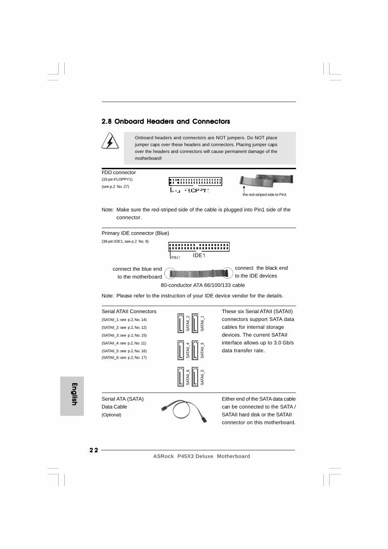
FDD connector(33-pin FLOPPY1)
(see p.2 No. 27)
Note: Make sure the red-striped side of the cable is plugged into Pin1 side of theconnector.
Primary IDE connector (Blue)(39-pin IDE1, see p.2 No. 9)
Note: Please refer to the instruction of your IDE device vendor for the details.
Serial ATAII Connectors These six Serial ATAII (SATAII)(SATAII_1: see p.2, No. 14) connectors support SATA data(SATAII_2: see p.2, No. 12) cables for internal storage(SATAII_3: see p.2, No. 15) devices. The current SATAII(SATAII_4: see p.2, No. 11) interface allows up to 3.0 Gb/s(SATAII_5: see p.2, No. 16) data transfer rate.(SATAII_6: see p.2, No. 17)
connect the black endto the IDE devices
connect the blue endto the motherboard
80-conductor ATA 66/100/133 cable
Serial ATA (SATA) Either end of the SATA data cableData Cable can be connected to the SATA /(Optional) SATAII hard disk or the SATAII
connector on this motherboard.
SATA
II_6
SATA
II_4
SATA
II_2
SATA
II_5
SATA
II_3
SATA
II_1
2 32 32 32 32 3ASRock P45X3 Deluxe Motherboard
connect to thepower supply
connect to the SATAHDD power connector
Eng
lish
Eng
lish
Eng
lish
Eng
lish
Eng
lish
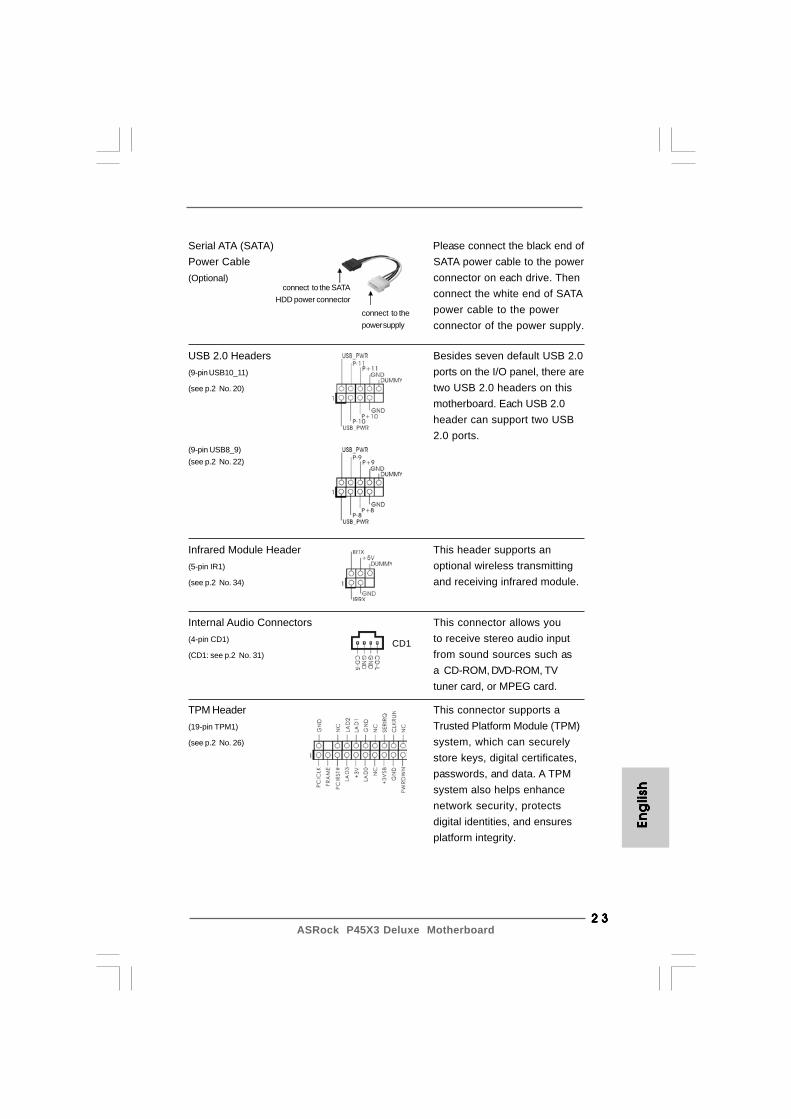
Serial ATA (SATA) Please connect the black end ofPower Cable SATA power cable to the power(Optional) connector on each drive. Then
connect the white end of SATApower cable to the powerconnector of the power supply.
Internal Audio Connectors This connector allows you(4-pin CD1) to receive stereo audio input(CD1: see p.2 No. 31) from sound sources such as
a CD-ROM, DVD-ROM, TVtuner card, or MPEG card.
USB 2.0 Headers Besides seven default USB 2.0(9-pin USB10_11) ports on the I/O panel, there are(see p.2 No. 20) two USB 2.0 headers on this
motherboard. Each USB 2.0header can support two USB2.0 ports.
(9-pin USB8_9)(see p.2 No. 22)
CD1
Infrared Module Header This header supports an(5-pin IR1) optional wireless transmitting(see p.2 No. 34) and receiving infrared module.
TPM Header This connector supports a(19-pin TPM1) Trusted Platform Module (TPM)(see p.2 No. 26) system, which can securely
store keys, digital certificates,passwords, and data. A TPMsystem also helps enhancenetwork security, protectsdigital identities, and ensuresplatform integrity.
2 42 42 42 42 4ASRock P45X3 Deluxe Motherboard
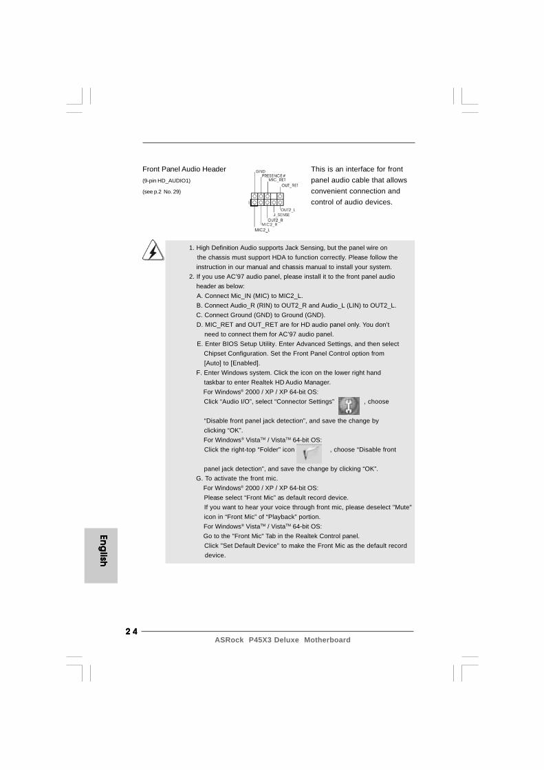
1. High Definition Audio supports Jack Sensing, but the panel wire on the chassis must support HDA to function correctly. Please follow the
instruction in our manual and chassis manual to install your system.2. If you use AC’97 audio panel, please install it to the front panel audio header as below: A. Connect Mic_IN (MIC) to MIC2_L. B. Connect Audio_R (RIN) to OUT2_R and Audio_L (LIN) to OUT2_L.
C. Connect Ground (GND) to Ground (GND). D. MIC_RET and OUT_RET are for HD audio panel only. You don’t need to connect them for AC’97 audio panel. E. Enter BIOS Setup Utility. Enter Advanced Settings, and then select
Chipset Configuration. Set the Front Panel Control option from [Auto] to [Enabled]. F. Enter Windows system. Click the icon on the lower right hand taskbar to enter Realtek HD Audio Manager. For Windows® 2000 / XP / XP 64-bit OS: Click “Audio I/O”, select “Connector Settings” , choose
“Disable front panel jack detection”, and save the change by clicking “OK”. For Windows® VistaTM / VistaTM 64-bit OS: Click the right-top “Folder” icon , choose “Disable front
panel jack detection”, and save the change by clicking “OK”. G. To activate the front mic. For Windows® 2000 / XP / XP 64-bit OS: Please select “Front Mic” as default record device. If you want to hear your voice through front mic, please deselect "Mute" icon in “Front Mic” of “Playback” portion. For Windows® VistaTM / VistaTM 64-bit OS: Go to the "Front Mic" Tab in the Realtek Control panel. Click "Set Default Device" to make the Front Mic as the default record device.
Front Panel Audio Header This is an interface for front(9-pin HD_AUDIO1) panel audio cable that allows(see p.2 No. 29) convenient connection and
control of audio devices.
Eng
lishEn
glish
Eng
lishEn
glish
Eng
lish

2 52 52 52 52 5ASRock P45X3 Deluxe Motherboard
Chassis Speaker Header Please connect the chassis(4-pin SPEAKER 1) speaker to this header.(see p.2 No. 25)
Though this motherboard provides 4-Pin CPU fan (Quiet Fan) support, the 3-Pin CPU fan still can work successfully even without the fan speed control function. If you plan to connect the 3-Pin CPU fan to the CPU fan connector on this motherboard, please connect it to Pin 1-3.
3-Pin Fan Installation
Pin 1-3 Connected
System Panel Header This header accommodates(9-pin PANEL1) several system front panel(see p.2 No. 24) functions.
ATX Power Connector Please connect an ATX power(24-pin ATXPWR1) supply to this connector.(see p.2 No. 8)
CPU Fan Connector Please connect a CPU fan cable(4-pin CPU_FAN1) to this connector and match(see p.2 No. 5) the black wire to the ground pin.
12
1
24
13
4 3 2 1
Eng
lish
Eng
lish
Eng
lish
Eng
lish
Eng
lish
Chassis, NB and Power Fan Connectors Please connect the fan cables(4-pin CHA_FAN1) to the fan connectors and(see p.2 No. 13) match the black wire to the
ground pin.
(3-pin NB_FAN1)(see p.2 No. 42)
(3-pin PWR_FAN1)(see p.2 No. 41)
2 62 62 62 62 6ASRock P45X3 Deluxe Motherboard
Eng
lishEn
glish
Eng
lishEn
glish
Eng
lish
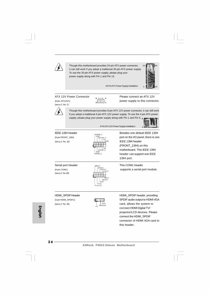
HDMI_SPDIF Header HDMI_SPDIF header, providing(3-pin HDMI_SPDIF1) SPDIF audio output to HDMI VGA(see p.2 No. 30) card, allows the system to
connect HDMI Digital TV/projector/LCD devices. Pleaseconnect the HDMI_SPDIFconnector of HDMI VGA card tothis header.
ATX 12V Power Connector Please connect an ATX 12V(8-pin ATX12V1) power supply to this connector.(see p.2 No. 2)
IEEE 1394 Header Besides one default IEEE 1394(9-pin FRONT_1394) port on the I/O panel, there is one(see p.2 No. 10) IEEE 1394 header
(FRONT_1394) on thismotherboard. This IEEE 1394header can support one IEEE1394 port.
4-Pin ATX 12V Power Supply Installation
Though this motherboard provides 8-pin ATX 12V power connector, it can still workif you adopt a traditional 4-pin ATX 12V power supply. To use the 4-pin ATX powersupply, please plug your power supply along with Pin 1 and Pin 5.
Serial port Header This COM1 header(9-pin COM1) supports a serial port module.(see p.2 No.28)
20-Pin ATX Power Supply Installation
Though this motherboard provides 24-pin ATX power connector,it can still work if you adopt a traditional 20-pin ATX power supply.To use the 20-pin ATX power supply, please plug yourpower supply along with Pin 1 and Pin 13.
12
1
24
13
8 5
4 1
8 5
4 1
2 72 72 72 72 7ASRock P45X3 Deluxe Motherboard
Eng
lish
Eng
lish
Eng
lish
Eng
lish
Eng
lish
12
1
24
13
8 5
4 1
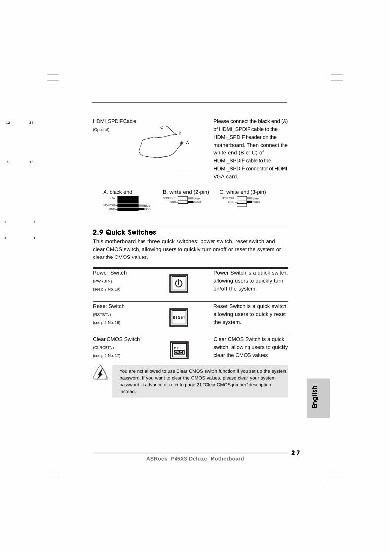
HDMI_SPDIF Cable Please connect the black end (A)(Optional) of HDMI_SPDIF cable to the
HDMI_SPDIF header on themotherboard. Then connect thewhite end (B or C) ofHDMI_SPDIF cable to theHDMI_SPDIF connector of HDMIVGA card.
A. black end B. white end (2-pin) C. white end (3-pin)
CB
A
2.9 Quick Switches2.9 Quick Switches2.9 Quick Switches2.9 Quick Switches2.9 Quick SwitchesThis motherboard has three quick switches: power switch, reset switch andclear CMOS switch, allowing users to quickly turn on/off or reset the system orclear the CMOS values.
Power Switch Power Switch is a quick switch,(PWRBTN) allowing users to quickly turn(see p.2 No. 19) on/off the system.
Reset Switch Reset Switch is a quick switch,(RSTBTN) allowing users to quickly reset(see p.2 No. 18) the system.
RESET
Clear CMOS Switch Clear CMOS Switch is a quick(CLRCBTN) switch, allowing users to quickly(see p.2 No. 17) clear the CMOS values
clr
CMOS
You are not allowed to use Clear CMOS switch function if you set up the systempassword. If you want to clear the CMOS values, please clean your systempassword in advance or refer to page 21 “Clear CMOS jumper” descriptioninstead.
2 82 82 82 82 8ASRock P45X3 Deluxe Motherboard
Eng
lishEn
glish
Eng
lishEn
glish
Eng
lish
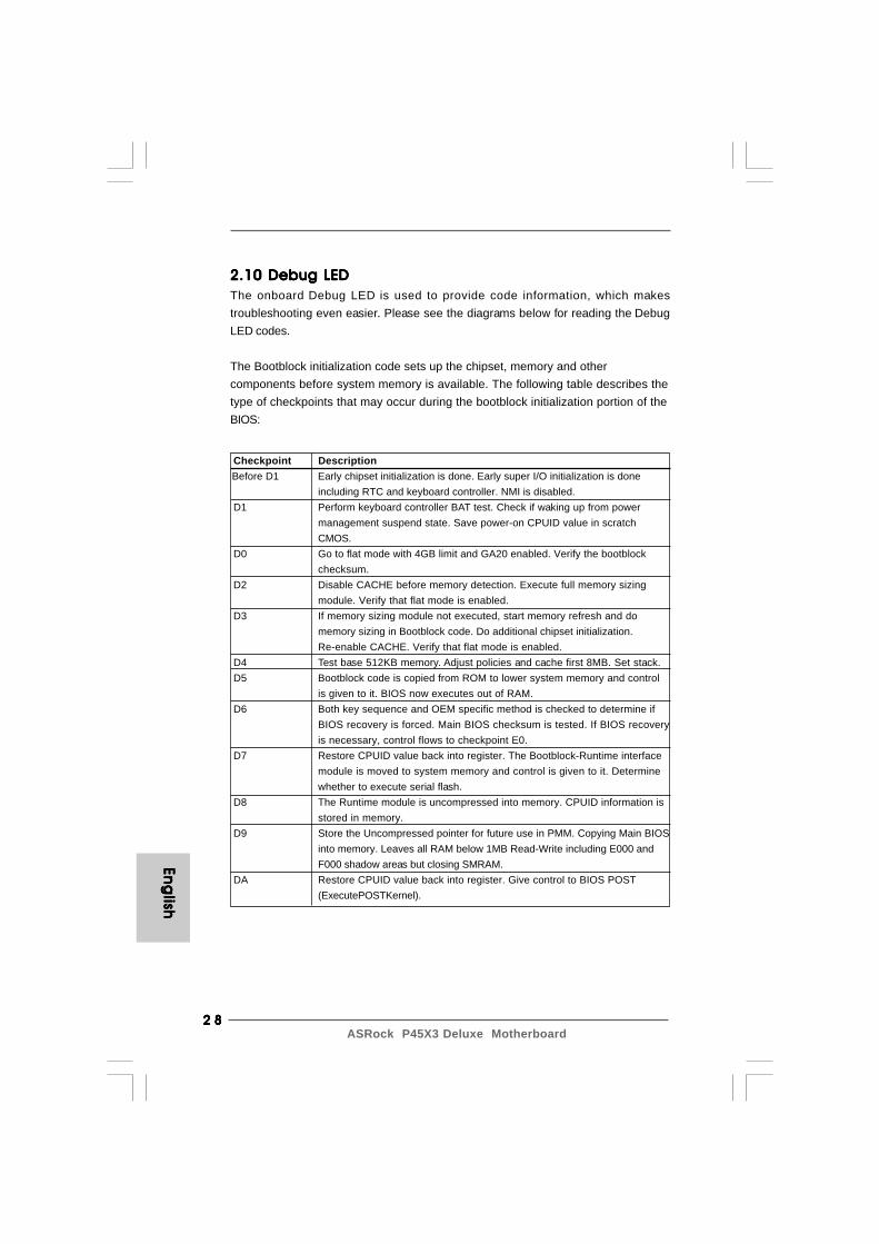
2.10 Debug LED2.10 Debug LED2.10 Debug LED2.10 Debug LED2.10 Debug LEDThe onboard Debug LED is used to provide code information, which makestroubleshooting even easier. Please see the diagrams below for reading the DebugLED codes.
The Bootblock initialization code sets up the chipset, memory and othercomponents before system memory is available. The following table describes thetype of checkpoints that may occur during the bootblock initialization portion of theBIOS:
Checkpoint Description
Before D1 Early chipset initialization is done. Early super I/O initialization is doneincluding RTC and keyboard controller. NMI is disabled.
D1 Perform keyboard controller BAT test. Check if waking up from powermanagement suspend state. Save power-on CPUID value in scratchCMOS.
D0 Go to flat mode with 4GB limit and GA20 enabled. Verify the bootblockchecksum.
D2 Disable CACHE before memory detection. Execute full memory sizingmodule. Verify that flat mode is enabled.
D3 If memory sizing module not executed, start memory refresh and domemory sizing in Bootblock code. Do additional chipset initialization.Re-enable CACHE. Verify that flat mode is enabled.
D4 Test base 512KB memory. Adjust policies and cache first 8MB. Set stack. D5 Bootblock code is copied from ROM to lower system memory and control
is given to it. BIOS now executes out of RAM. D6 Both key sequence and OEM specific method is checked to determine if
BIOS recovery is forced. Main BIOS checksum is tested. If BIOS recoveryis necessary, control flows to checkpoint E0.
D7 Restore CPUID value back into register. The Bootblock-Runtime interfacemodule is moved to system memory and control is given to it. Determinewhether to execute serial flash.
D8 The Runtime module is uncompressed into memory. CPUID information isstored in memory.
D9 Store the Uncompressed pointer for future use in PMM. Copying Main BIOSinto memory. Leaves all RAM below 1MB Read-Write including E000 andF000 shadow areas but closing SMRAM.
DA Restore CPUID value back into register. Give control to BIOS POST(ExecutePOSTKernel).
2 92 92 92 92 9ASRock P45X3 Deluxe Motherboard
Eng
lish
Eng
lish
Eng
lish
Eng
lish
Eng
lish
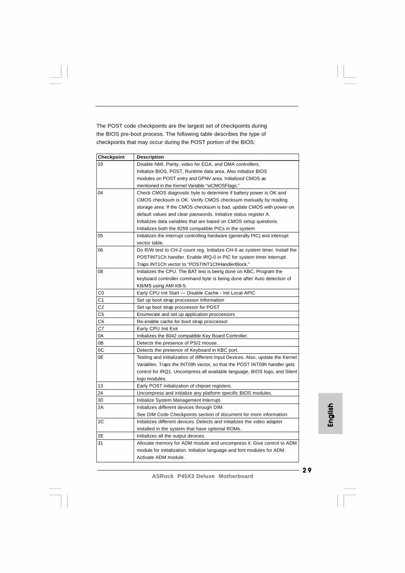
The POST code checkpoints are the largest set of checkpoints duringthe BIOS pre-boot process. The following table describes the type ofcheckpoints that may occur during the POST portion of the BIOS:
Checkpoint Description 03 Disable NMI, Parity, video for EGA, and DMA controllers.
Initialize BIOS, POST, Runtime data area. Also initialize BIOSmodules on POST entry and GPNV area. Initialized CMOS asmentioned in the Kernel Variable “wCMOSFlags.”
04 Check CMOS diagnostic byte to determine if battery power is OK andCMOS checksum is OK. Verify CMOS checksum manually by readingstorage area. If the CMOS checksum is bad, update CMOS with power-ondefault values and clear passwords. Initialize status register A.Initializes data variables that are based on CMOS setup questions.Initializes both the 8259 compatible PICs in the system
05 Initializes the interrupt controlling hardware (generally PIC) and interruptvector table.
06 Do R/W test to CH-2 count reg. Initialize CH-0 as system timer. Install thePOSTINT1Ch handler. Enable IRQ-0 in PIC for system timer interrupt.Traps INT1Ch vector to “POSTINT1ChHandlerBlock.”
08 Initializes the CPU. The BAT test is being done on KBC. Program thekeyboard controller command byte is being done after Auto detection ofKB/MS using AMI KB-5.
C0 Early CPU Init Start — Disable Cache - Init Local APIC C1 Set up boot strap proccessor Information C2 Set up boot strap proccessor for POST C5 Enumerate and set up application proccessors C6 Re-enable cache for boot strap proccessor C7 Early CPU Init Exit 0A Initializes the 8042 compatible Key Board Controller. 0B Detects the presence of PS/2 mouse. 0C Detects the presence of Keyboard in KBC port. 0E Testing and initialization of different Input Devices. Also, update the Kernel
Variables. Traps the INT09h vector, so that the POST INT09h handler getscontrol for IRQ1. Uncompress all available language, BIOS logo, and Silentlogo modules.
13 Early POST initialization of chipset registers. 24 Uncompress and initialize any platform specific BIOS modules. 30 Initialize System Management Interrupt. 2A Initializes different devices through DIM.
See DIM Code Checkpoints section of document for more information. 2C Initializes different devices. Detects and initializes the video adapter
installed in the system that have optional ROMs. 2E Initializes all the output devices. 31 Allocate memory for ADM module and uncompress it. Give control to ADM
module for initialization. Initialize language and font modules for ADM.Activate ADM module.
3 03 03 03 03 0ASRock P45X3 Deluxe Motherboard
Eng
lishEn
glish
Eng
lishEn
glish
Eng
lish
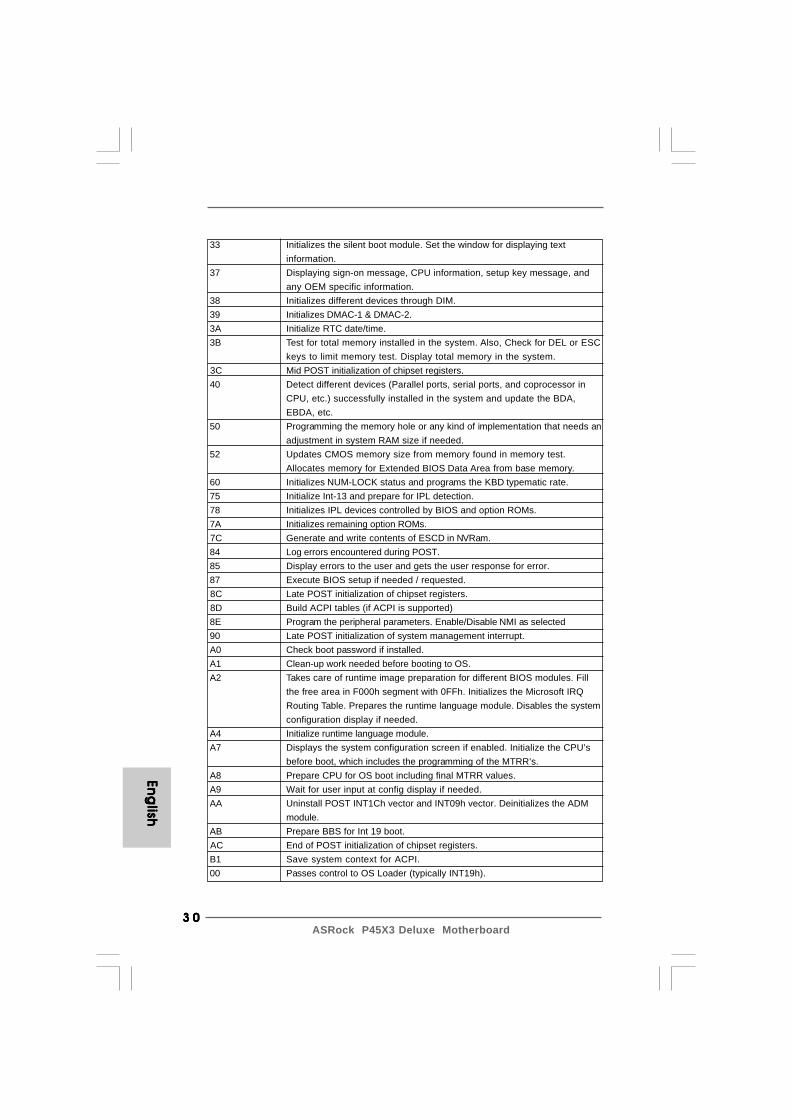
33 Initializes the silent boot module. Set the window for displaying textinformation.
37 Displaying sign-on message, CPU information, setup key message, andany OEM specific information.
38 Initializes different devices through DIM. 39 Initializes DMAC-1 & DMAC-2. 3A Initialize RTC date/time. 3B Test for total memory installed in the system. Also, Check for DEL or ESC
keys to limit memory test. Display total memory in the system. 3C Mid POST initialization of chipset registers. 40 Detect different devices (Parallel ports, serial ports, and coprocessor in
CPU, etc.) successfully installed in the system and update the BDA,EBDA, etc.
50 Programming the memory hole or any kind of implementation that needs anadjustment in system RAM size if needed.
52 Updates CMOS memory size from memory found in memory test.Allocates memory for Extended BIOS Data Area from base memory.
60 Initializes NUM-LOCK status and programs the KBD typematic rate. 75 Initialize Int-13 and prepare for IPL detection. 78 Initializes IPL devices controlled by BIOS and option ROMs. 7A Initializes remaining option ROMs. 7C Generate and write contents of ESCD in NVRam. 84 Log errors encountered during POST. 85 Display errors to the user and gets the user response for error. 87 Execute BIOS setup if needed / requested. 8C Late POST initialization of chipset registers. 8D Build ACPI tables (if ACPI is supported) 8E Program the peripheral parameters. Enable/Disable NMI as selected 90 Late POST initialization of system management interrupt. A0 Check boot password if installed. A1 Clean-up work needed before booting to OS. A2 Takes care of runtime image preparation for different BIOS modules. Fill
the free area in F000h segment with 0FFh. Initializes the Microsoft IRQRouting Table. Prepares the runtime language module. Disables the systemconfiguration display if needed.
A4 Initialize runtime language module. A7 Displays the system configuration screen if enabled. Initialize the CPU’s
before boot, which includes the programming of the MTRR’s. A8 Prepare CPU for OS boot including final MTRR values. A9 Wait for user input at config display if needed. AA Uninstall POST INT1Ch vector and INT09h vector. Deinitializes the ADM
module. AB Prepare BBS for Int 19 boot. AC End of POST initialization of chipset registers. B1 Save system context for ACPI. 00 Passes control to OS Loader (typically INT19h).
3 13 13 13 13 1ASRock P45X3 Deluxe Motherboard
Eng
lish
Eng
lish
Eng
lish
Eng
lish
Eng
lish
2.112.112.112.112.11 Driver Installation Guide Driver Installation Guide Driver Installation Guide Driver Installation Guide Driver Installation GuideTo install the drivers to your system, please insert the support CD to your opticaldrive first. Then, the drivers compatible to your system can be auto-detected andlisted on the support CD driver page. Please follow the order from up to bottomside to install those required drivers. Therefore, the drivers you install can workproperly.
2.122.122.122.122.12 Installing WindowsInstalling WindowsInstalling WindowsInstalling WindowsInstalling Windows®®®®® 2000 / XP / XP 64-bit / Vista 2000 / XP / XP 64-bit / Vista 2000 / XP / XP 64-bit / Vista 2000 / XP / XP 64-bit / Vista 2000 / XP / XP 64-bit / VistaTM TM TM TM TM /////
VistaVistaVistaVistaVistaTMTMTMTMTM 64-bit Without RAID Functions 64-bit Without RAID Functions 64-bit Without RAID Functions 64-bit Without RAID Functions 64-bit Without RAID FunctionsIf you want to install Windows® 2000 / XP / XP 64-bit / VistaTM / VistaTM 64-bit OS onyour SATA / SATAII HDDs without RAID functions, please follow below proceduresaccording to the OS you install.
Since Windows® 2000 AHCI driver is not provided by the chipset vendor,AHCI function is not supported under Windows® 2000.
2.12.1 Installing Windows2.12.1 Installing Windows2.12.1 Installing Windows2.12.1 Installing Windows2.12.1 Installing Windows®®®®® 2000 / XP / XP 64-bit 2000 / XP / XP 64-bit 2000 / XP / XP 64-bit 2000 / XP / XP 64-bit 2000 / XP / XP 64-bit
Without RAID Functions Without RAID Functions Without RAID Functions Without RAID Functions Without RAID FunctionsIf you want to install Windows® 2000 / XP / XP 64-bit OS on your SATA / SATAII HDDswithout RAID functions, please follow below steps.
STEP 1: Set up BIOS.A. Enter BIOS SETUP UTILITY Advanced screen IDE Configuration.B. Set “SATAII Configuration” to [Enhanced], and then in the option “Configure SATAII as”, please set the option to [IDE].STEP 2: Install Windows® 2000 / XP / XP 64-bit OS on your system.
Using SATA / SATAII HDDs without NCQ function
2.12.2 Installing Windows2.12.2 Installing Windows2.12.2 Installing Windows2.12.2 Installing Windows2.12.2 Installing Windows®®®®® Vista Vista Vista Vista VistaTM TM TM TM TM / Vista/ Vista/ Vista/ Vista/ VistaTMTMTMTMTM 64-bit 64-bit 64-bit 64-bit 64-bit
Without RAID Functions Without RAID Functions Without RAID Functions Without RAID Functions Without RAID FunctionsIf you want to install Windows® VistaTM / VistaTM 64-bit OS on your SATA / SATAIIHDDs without RAID functions, please follow below steps.
Using SATA / SATAII HDDs without NCQ function
STEP 1: Set up BIOS.A. Enter BIOS SETUP UTILITY Advanced screen IDE Configuration.B. Set “SATAII Configuration” to [Enhanced], and then in the option “Configure SATAII as”, please set the option to [IDE].STEP 2: Install Windows® VistaTM / VistaTM 64-bit OS on your system.
3 23 23 23 23 2ASRock P45X3 Deluxe Motherboard
Using SATA / SATAII HDDs with NCQ function
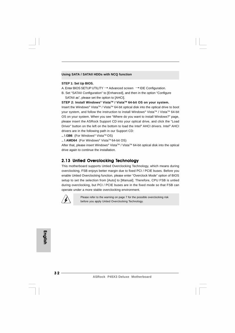
STEP 1: Set Up BIOS.A. Enter BIOS SETUP UTILITY Advanced screen IDE Configuration.B. Set “SATAII Configuration” to [Enhanced], and then in the option “Configure SATAII as”, please set the option to [AHCI].STEP 2: Install Windows® VistaTM / VistaTM 64-bit OS on your system.Insert the Windows® VistaTM / VistaTM 64-bit optical disk into the optical drive to bootyour system, and follow the instruction to install Windows® VistaTM / VistaTM 64-bitOS on your system. When you see “Where do you want to install Windows?” page,please insert the ASRock Support CD into your optical drive, and click the “LoadDriver” button on the left on the bottom to load the Intel® AHCI drivers. Intel® AHCIdrivers are in the following path in our Support CD:.. \ I386 (For Windows® VistaTM OS).. \ AMD64 (For Windows® VistaTM 64-bit OS)After that, please insert Windows® VistaTM / VistaTM 64-bit optical disk into the opticaldrive again to continue the installation.
2.132.132.132.132.13 Untied Overclocking TUntied Overclocking TUntied Overclocking TUntied Overclocking TUntied Overclocking TechnologyechnologyechnologyechnologyechnologyThis motherboard supports Untied Overclocking Technology, which means duringoverclocking, FSB enjoys better margin due to fixed PCI / PCIE buses. Before youenable Untied Overclocking function, please enter “Overclock Mode” option of BIOSsetup to set the selection from [Auto] to [Manual]. Therefore, CPU FSB is untiedduring overclocking, but PCI / PCIE buses are in the fixed mode so that FSB canoperate under a more stable overclocking environment.
Please refer to the warning on page 7 for the possible overclocking riskbefore you apply Untied Overclocking Technology.
Eng
lishEn
glish
Eng
lishEn
glish
Eng
lish
3 33 33 33 33 3ASRock P45X3 Deluxe Motherboard
3. BIOS Information3. BIOS Information3. BIOS Information3. BIOS Information3. BIOS InformationThe Flash Memory on the motherboard stores BIOS Setup Utility. When you start upthe computer, please press <F2> during the Power-On-Self-Test (POST) to enterBIOS Setup utility; otherwise, POST continues with its test routines. If you wish toenter BIOS Setup after POST, please restart the system by pressing <Ctl> + <Alt> +<Delete>, or pressing the reset button on the system chassis. The BIOS Setupprogram is designed to be user-friendly. It is a menu-driven program, which allowsyou to scroll through its various sub-menus and to select among the predeterminedchoices. For the detailed information about BIOS Setup, please refer to the UserManual (PDF file) contained in the Support CD.
4. Sof4. Sof4. Sof4. Sof4. Software Supportware Supportware Supportware Supportware Support CD informationt CD informationt CD informationt CD informationt CD informationThis motherboard supports various Microsoft® Windows® operating systems: 2000 /XP / XP 64-bit / VistaTM / VistaTM 64-bit. The Support CD that came with the motherboardcontains necessary drivers and useful utilities that will enhance motherboard features.To begin using the Support CD, insert the CD into your CD-ROM drive. It will displaythe Main Menu automatically if “AUTORUN” is enabled in your computer. If the MainMenu does not appear automatically, locate and double-click on the file “ASSETUP.EXE” from the BIN folder in the Support CD to display the menus.
Eng
lish
Eng
lish
Eng
lish
Eng
lish
Eng
lish
3 43 43 43 43 4ASRock P45X3 Deluxe Motherboard
De
utsc
hD
eu
tsch
De
utsc
hD
eu
tsch
De
utsc
h
1. Einführung1. Einführung1. Einführung1. Einführung1. EinführungWir danken Ihnen für den Kauf des ASRock P45X3 Deluxe Motherboard, einzuverlässiges Produkt, welches unter den ständigen, strengen Qualitätskontrollenvon ASRock gefertigt wurde. Es bietet Ihnen exzellente Leistung und robustes Design,gemäß der Verpflichtung von ASRock zu Qualität und Halbarkeit. DieseSchnellinstallationsanleitung führt in das Motherboard und die schrittweise Installa-tion ein. Details über das Motherboard finden Sie in der Bedienungsanleitung auf derSupport-CD.
Da sich Motherboard-Spezifikationen und BIOS-Software verändernkönnen, kann der Inhalt dieses Handbuches ebenfalls jederzeit geändertwerden. Für den Fall, dass sich Änderungen an diesem Handbuchergeben, wird eine neue Version auf der ASRock-Website, ohne weitereAnkündigung, verfügbar sein. Die neuesten Grafikkarten und unterstütztenCPUs sind auch auf der ASRock-Website aufgelistet.ASRock-Website: http://www.asrock.comWenn Sie technische Unterstützung zu Ihrem Motherboard oder spezifischeInformationen zu Ihrem Modell benötigen, besuchen Sie bitte unsereWebseite:www.asrock.com/support/index.asp
1.1 Kartoninhalt1.1 Kartoninhalt1.1 Kartoninhalt1.1 Kartoninhalt1.1 KartoninhaltASRock P45X3 Deluxe Motherboard
(ATX-Formfaktor: 30.5 cm x 24.4 cm; 12.0 Zoll x 9.6 Zoll)ASRock P45X3 Deluxe SchnellinstallationsanleitungASRock P45X3 Deluxe Support-CDEine ASRock SLI/XFire-Switch-KarteEin 80-adriges Ultra-ATA 66/100/133 IDE-FlachbandkabelEin Flachbandkabel für ein 3,5-Zoll-DiskettenlaufwerkVier Serial ATA (SATA) -Datenkabel (optional)Ein Serial ATA (SATA) -Festplattenstromkabel (optional)Ein I/O Shield
3 53 53 53 53 5ASRock P45X3 Deluxe Motherboard
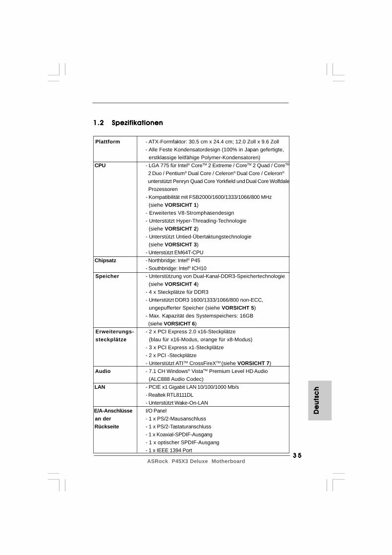
1.21.21.21.21.2 SpezifikationenSpezifikationenSpezifikationenSpezifikationenSpezifikationen
Plattform - ATX-Formfaktor: 30.5 cm x 24.4 cm; 12.0 Zoll x 9.6 Zoll- Alle Feste Kondensatordesign (100% in Japan gefertigte, erstklassige leitfähige Polymer-Kondensatoren)
CPU - LGA 775 für Intel® CoreTM 2 Extreme / CoreTM 2 Quad / CoreTM
2 Duo / Pentium® Dual Core / Celeron® Dual Core / Celeron®
unterstützt Penryn Quad Core Yorkfield und Dual Core Wolfdale Prozessoren- Kompatibilität mit FSB2000/1600/1333/1066/800 MHz (siehe VORSICHT 1)- Erweitertes V8-Stromphasendesign- Unterstützt Hyper-Threading-Technologie (siehe VORSICHT 2)- Unterstützt Untied-Übertaktungstechnologie (siehe VORSICHT 3)- Unterstützt EM64T-CPU
Chipsatz - Northbridge: Intel® P45- Southbridge: Intel® ICH10
Speicher - Unterstützung von Dual-Kanal-DDR3-Speichertechnologie (siehe VORSICHT 4)- 4 x Steckplätze für DDR3- Unterstützt DDR3 1600/1333/1066/800 non-ECC, ungepufferter Speicher (siehe VORSICHT 5)- Max. Kapazität des Systemspeichers: 16GB (siehe VORSICHT 6)
Erweiterungs- - 2 x PCI Express 2.0 x16-Steckplätze steckplätze (blau für x16-Modus, orange für x8-Modus)
- 3 x PCI Express x1-Steckplätze- 2 x PCI -Steckplätze- Unterstützt ATITM CrossFireXTM (siehe VORSICHT 7)
Audio - 7.1 CH Windows® VistaTM Premium Level HD Audio (ALC888 Audio Codec)
LAN - PCIE x1 Gigabit LAN 10/100/1000 Mb/s- Realtek RTL8111DL- Unterstützt Wake-On-LAN
E/A-Anschlüsse I/O Panel an der - 1 x PS/2-Mausanschluss Rückseite - 1 x PS/2-Tastaturanschluss
- 1 x Koaxial-SPDIF-Ausgang- 1 x optischer SPDIF-Ausgang- 1 x IEEE 1394 Port
De
uts
ch
De
uts
ch
De
uts
ch
De
uts
ch
De
uts
ch
3 63 63 63 63 6ASRock P45X3 Deluxe Motherboard
De
utsc
hD
eu
tsch
De
utsc
hD
eu
tsch
De
utsc
h
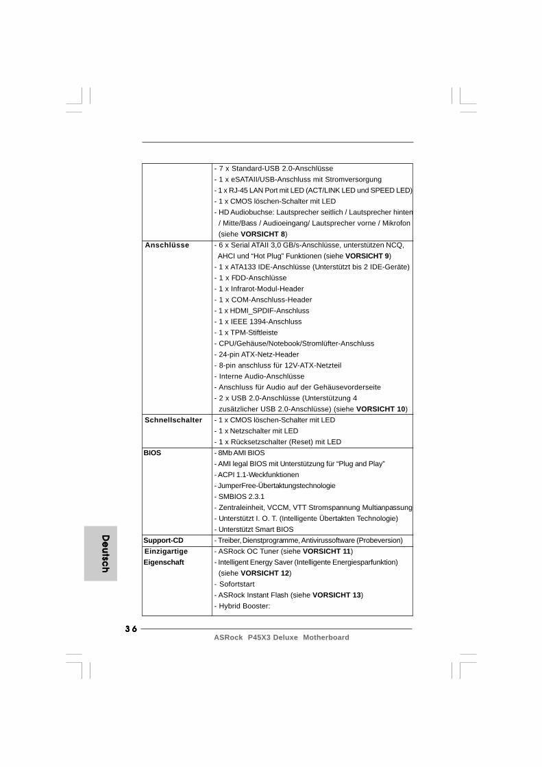
- 7 x Standard-USB 2.0-Anschlüsse- 1 x eSATAII/USB-Anschluss mit Stromversorgung- 1 x RJ-45 LAN Port mit LED (ACT/LINK LED und SPEED LED)- 1 x CMOS löschen-Schalter mit LED- HD Audiobuchse: Lautsprecher seitlich / Lautsprecher hinten / Mitte/Bass / Audioeingang/ Lautsprecher vorne / Mikrofon (siehe VORSICHT 8)
Anschlüsse - 6 x Serial ATAII 3,0 GB/s-Anschlüsse, unterstützen NCQ, AHCI und “Hot Plug” Funktionen (siehe VORSICHT 9)- 1 x ATA133 IDE-Anschlüsse (Unterstützt bis 2 IDE-Geräte)- 1 x FDD-Anschlüsse- 1 x Infrarot-Modul-Header- 1 x COM-Anschluss-Header- 1 x HDMI_SPDIF-Anschluss- 1 x IEEE 1394-Anschluss- 1 x TPM-Stiftleiste- CPU/Gehäuse/Notebook/Stromlüfter-Anschluss- 24-pin ATX-Netz-Header- 8-pin anschluss für 12V-ATX-Netzteil- Interne Audio-Anschlüsse- Anschluss für Audio auf der Gehäusevorderseite- 2 x USB 2.0-Anschlüsse (Unterstützung 4 zusätzlicher USB 2.0-Anschlüsse) (siehe VORSICHT 10)
Schnellschalter - 1 x CMOS löschen-Schalter mit LED- 1 x Netzschalter mit LED- 1 x Rücksetzschalter (Reset) mit LED
BIOS - 8Mb AMI BIOS- AMI legal BIOS mit Unterstützung für “Plug and Play”- ACPI 1.1-Weckfunktionen- JumperFree-Übertaktungstechnologie- SMBIOS 2.3.1- Zentraleinheit, VCCM, VTT Stromspannung Multianpassung- Unterstützt I. O. T. (Intelligente Übertakten Technologie)- Unterstützt Smart BIOS
Support-CD - Treiber, Dienstprogramme, Antivirussoftware (Probeversion) Einzigartige - ASRock OC Tuner (siehe VORSICHT 11) Eigenschaft - Intelligent Energy Saver (Intelligente Energiesparfunktion)
(siehe VORSICHT 12)- Sofortstart- ASRock Instant Flash (siehe VORSICHT 13)- Hybrid Booster:

3 73 73 73 73 7ASRock P45X3 Deluxe Motherboard
WARNUNGBeachten Sie bitte, dass Overclocking, einschließlich der Einstellung im BIOS, Anwendender Untied Overclocking-Technologie oder Verwenden von Overclocking-Werkzeugen vonDritten, mit einem gewissen Risiko behaftet ist. Overclocking kann sich nachteilig auf dieStabilität Ihres Systems auswirken oder sogar Komponenten und Geräte Ihres Systemsbeschädigen. Es geschieht dann auf eigene Gefahr und auf Ihre Kosten. Wir übernehmenkeine Verantwortung für mögliche Schäden, die aufgrund von Overclocking verursachtwurden.
VORSICHT!1. Einige von Ihnen verwendete CPUs könnten auf FSB2000 MHz
übertaktet sein. Verwenden Sie in diesem Fall DDR3 1333 oder DDR31600-Speichermodule auf diesem Motherboard.
2. Die Einstellung der “Hyper-Threading Technology”, finden Sie aufSeite 49 des auf der Support-CD enthaltenen Benutzerhandbuchesbeschrieben.
3. Dieses Motherboard unterstützt die Untied-Übertaktungstechnologie.Unter “Entkoppelte Übertaktungstechnologie” auf Seite 57 finden Siedetaillierte Informationen.
4. Dieses Motherboard unterstützt Dual-Kanal-Speichertechnologie. VorImplementierung der Dual-Kanal-Speichertechnologie müssen Sie dieInstallationsanleitung für die Speichermodule auf Seite 44 zwecks richtigerInstallation gelesen haben.
5. Die unterstützten Arbeitsspeicherfrequenzen und die entsprechendeCPU FSB-Frequenz entnehmen Sie bitte der nachstehenden Tabelle.
CPU FSB-Frequenz Unterstützte Arbeitsspeicherfrequenz1600 DDR3 800, DDR3 1066, DDR3 1333,
DDR3 16001333 DDR3 800, DDR3 1066, DDR3 13331066 DDR3 800, DDR3 1066800 DDR3 800
De
uts
ch
De
uts
ch
De
uts
ch
De
uts
ch
De
uts
ch
- Schrittloser CPU-Frequenz-Kontrolle (siehe VORSICHT 14)- ASRock U-COP (siehe VORSICHT 15)- Boot Failure Guard (B.F.G. – Systemstartfehlerschutz)
Hardware Monitor - Überwachung der CPU-Temperatur- Motherboardtemperaturerkennung- Drehzahlmessung für CPU/Gehäuse/Notebook/Stromlüfter- CPU-Lüftergeräuschdämpfung- Spannungsüberwachung: +12V, +5V, +3.3V, Vcore
Betriebssysteme - Unterstützt Microsoft® Windows® 2000 / XP / XP 64-Bit / VistaTM / VistaTM 64-Bit (siehe VORSICHT 16)
Zertifizierungen - FCC, CE, WHQL * Für die ausführliche Produktinformation, besuchen Sie bitte unsere Website: http://www.asrock.com
3 83 83 83 83 8ASRock P45X3 Deluxe Motherboard
De
utsc
hD
eu
tsch
De
utsc
hD
eu
tsch
De
utsc
h
* DDR3 1600 Speichermodule werden in Übertakten Modusfunktionieren.
6. Durch Betriebssystem-Einschränkungen kann die tatsächlicheSpeichergröße weniger als 4 GB betragen, da unter Windows® XP undWindows® Vista™ etwas Speicher zur Nutzung durch das System reserviertwird. Unter Windows® XP 64-bit und Windows® Vista™ 64-bit mit 64-Bit-CPUbesteht diese Einschränkung nicht.
7. Dieses Motherboard unterstützt ATITM CrossFireXTM-Technologie. MächtenSie die CrossFireXTM-Funktion verwenden, kehren Sie bitte die Richtungder ASRock SLI/XFire-Switch-Karte gemäß den Anweisungen auf Seite 17im voraus um.
8. Der Mikrofoneingang dieses Motherboards unterstützt Stereo- und Mono-Modi. Der Audioausgang dieses Motherboards unterstützt 2-Kanal-, 4-Kanal-, 6-Kanal- und 8-Kanal-Modi. Stellen Sie die richtige Verbindunganhand der Tabelle auf Seite 3 her.
9. Vor Installation der SATAII-Festplatte an den SATAII-Anschluss lesen Siebitte “Setup-Anleitung für SATAII-Festplatte” auf Seite 37 der“Bedienungsanleitung” auf der Support-CD, um Ihre SATAII-Festplattedem SATAII-Modus anzugleichen. Sie können die SATA-Festplatte auchdirekt mit dem SATAII-Anschluss verbinden.
10. Das Power Management für USB 2.0 arbeitet unter Microsoft® Windows®
VistaTM 64-Bit / VistaTM / XP 64-Bit / XP SP1 oder SP2/2000 SP4einwandfrei.
11. Es ist ein benutzerfreundlicher ASRock Übertaktenswerkzeug, daserlaubt, dass Sie Ihr System durch den Hardware-Monitor Funktion zuüberblicken und Ihre Hardware-Geräte übertakten, um die besteSystemleistung unter der Windows® Umgebung zu erreichen. BesuchenSie bitte unsere Website für die Operationsverfahren von ASRock OCTuner. ASRock-Website: http://www.asrock.com
12. Mit einem fortschrittlichen, eigenständigen Hard- und Softwaredesignnutzt der Intelligent Energy Saver eine revolutionäre Technologie, diebisher unerreichte Energieeinsparungen ermöglicht. Mit anderen Worten:Sie verbrauchen besonders wenig Energie und erreichen einen hohenWirkungsgrad, ohne dass dies zu Lasten der Rechenleistung geht. Aufunseren Internetseiten finden Sie einige Erläuterungen zurFunktionsweise des Intelligent Energy Saver.ASRock-Website: http://www.asrock.com
13. ASRock Instant Flash ist ein im Flash-ROM eingebettetes BIOS-Flash-Programm. Mithilfe dieses praktischen BIOS-Aktualisierungswerkzeugskönnen Sie das System-BIOS aktualisieren, ohne dafür zuerstBetriebssysteme wie MS-DOS oder Windows® aufrufen zu müssen. Mitdiesem Programm bekommen Sie durch Drücken der <F6>-Tastewährend des POST-Vorgangs oder durch Drücken der <F2>-Taste imBIOS-Setup-Menü Zugang zu ASRock Instant Flash. Sie brauchen diesesWerkzeug einfach nur zu starten und die neue BIOS-Datei auf IhremUSB-Flash-Laufwerk, Diskettenlaufwerk oder der Festplatte zu
3 93 93 93 93 9ASRock P45X3 Deluxe Motherboard
De
uts
ch
De
uts
ch
De
uts
ch
De
uts
ch
De
uts
ch
speichern, und schon können Sie Ihr BIOS mit nur wenigen Klickvorgängenohne Bereitstellung einer zusätzlichen Diskette oder eines anderenkomplizierten Flash-Programms aktualisieren. Achten Sie darauf, dassdas USB-Flash-Laufwerk oder die Festplatte das Dateisystem FAT32/16/12 benutzen muss.
14. Obwohl dieses Motherboard stufenlose Steuerung bietet, wird Over-clocking nicht empfohlen. Frequenzen, die über den für den jeweiligenProzessor vorgesehenen liegen, können das System instabil werdenlassen oder die CPU beschädigen.
15. Wird eine Überhitzung der CPU registriert, führt das System einenautomatischen Shutdown durch. Bevor Sie das System neu starten, prüfenSie bitte, ob der CPU-Lüfter am Motherboard richtig funktioniert, undstecken Sie bitte den Stromkabelstecker aus und dann wieder ein. Um dieWärmeableitung zu verbessern, bitte nicht vergessen, etwas Wärmeleitpastezwischen CPU und Kühlkörper zu sprühen.
16. AHCI Funktionen werden unter Windows® 2000 Betriebssystem nichtunterstützt. Wir empfehlen, unter Windows® 2000 den IDE-Modus zu nutzen.Detail l ierte Einrichtungshinweise finden Sie auf Seite 59 der„Bedienungsanleitung“ auf der Unterstützungs-CD.
4 04 04 04 04 0ASRock P45X3 Deluxe Motherboard
De
utsc
hD
eu
tsch
De
utsc
hD
eu
tsch
De
utsc
h
2. Installation2. Installation2. Installation2. Installation2. Installation
Sicherheitshinweise vor der MontageSicherheitshinweise vor der MontageSicherheitshinweise vor der MontageSicherheitshinweise vor der MontageSicherheitshinweise vor der MontageBitte nehmen Sie die folgende Sicherheitshinweise zur Kenntnis, bevor Sie dasMotherboard einbauen oder Veränderungen an den Einstellungen vornehmen.
1. Trennen Sie das System vom Stromnetz, bevor Sie eine ystemkomponenteberühren, da es sonst zu schweren Schäden am Motherboard oder densonstigen internen, bzw. externen omponenten kommen kann.
2. Um Schäden aufgrund von statischer Elektrizität zu vermeiden, dasMotherboard NIEMALS auf einen Teppich o.ä.legen. Denken Sie außeremdaran, immer ein geerdetes Armband zu tragen oder ein geerdetes Objektaus Metall zu berühren, bevor Sie mit Systemkomponenten hantieren.
3. Halten Sie Komponenten immer an den Rändern und vermeiden SieBerührungen mit den ICs.
4. Wenn Sie Komponenten ausbauen, legen Sie sie immer auf eineantistatische Unterlage, oder zurück in die Tüte, mit der die Komponentegeliefert wurde.
5. Wenn Sie das Motherboard mit den Schrauben an dem Computergehäusebefestigen, überziehen Sie bitte die Schrauben nicht! Das Motherboard kannsonst beschädigt werden.
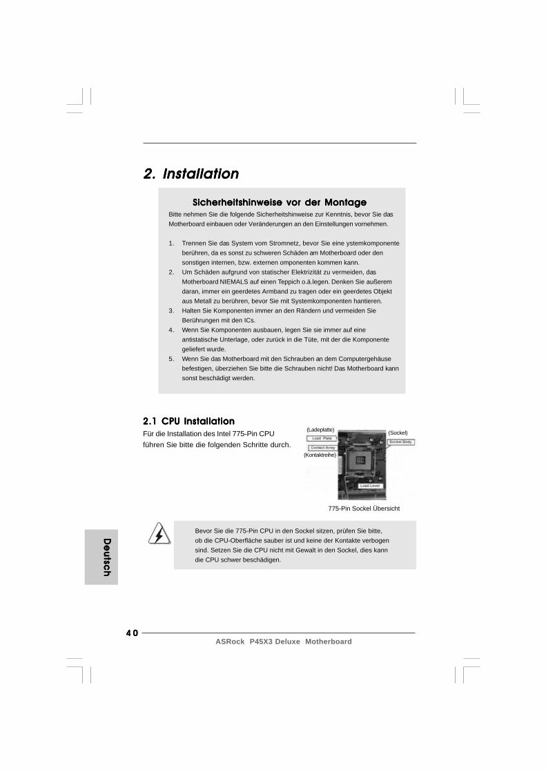
2.1 CPU Installation2.1 CPU Installation2.1 CPU Installation2.1 CPU Installation2.1 CPU InstallationFür die Installation des Intel 775-Pin CPUführen Sie bitte die folgenden Schritte durch.
Bevor Sie die 775-Pin CPU in den Sockel sitzen, prüfen Sie bitte,ob die CPU-Oberfläche sauber ist und keine der Kontakte verbogensind. Setzen Sie die CPU nicht mit Gewalt in den Sockel, dies kanndie CPU schwer beschädigen.
775-Pin Sockel Übersicht
(Ladeplatte)
(Kontaktreihe)
(Sockel)

4 14 14 14 14 1ASRock P45X3 Deluxe Motherboard
Schritt 1. Öffnen Sie den Sockel:Schritt 1-1. Öffnen Sie den Hebel, indem
Sie ihn nach unten drücken undaushaken.
Schritt 1-2. Drehen Sie den Ladehebel, biser in geöffneter Position steht,ca. 135 Grad.
Schritt 1-3. Drehen Sie die Ladeplatte, bissie in geöffneter Position steht,ca. 100 Grad.
Schritt 2. 775-Pin CPU einstecken:Schritt 2-1. Halten Sie die CPU an den mit
schwarzen Liniengekennzeichneten Seiten.
Schritt 2-2. Halten Sie das Teil mit dem IHS(Integrated Heat Sink –integrierter Kühlkörper) nachoben. Suchen Sie Pin 1 und diezweiOrientierungseinkerbungen.
Um die CPU ordnungsgemäß einsetzen zu können, richten Sie diezwei Orientierungskerben der CPU mit den beiden Markierungen desSockels aus.
Schritt 2-3. Drücken Sie die CPU vorsichtigin vertikaler Richtung in denSockel.
Schwarze Linie
775-Pin CPU
775-Pin Sockel
Pin1AusrichtungsmarkierungPin1
Orientierungskerbe
Schwarze Linie
Orientierungskerbe
Ausrichtungsmarkierung
De
uts
ch
De
uts
ch
De
uts
ch
De
uts
ch
De
uts
ch
4 24 24 24 24 2ASRock P45X3 Deluxe Motherboard
De
utsc
hD
eu
tsch
De
utsc
hD
eu
tsch
De
utsc
h
Schritt 2-4. Prüfen Sie, dass die CPUordnungsgemäß im Sockel sitztund die Orientierungskerbeneinwandfrei in denentsprechenden Auskerbungensitzen.
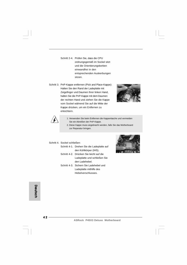
Schritt 3. PnP-Kappe entfernen (Pick and Place-Kappe):Halten Sie den Rand der Ladeplatte mitZeigefinger und Daumen Ihrer linken Hand,halten Sie die PnP-Kappe mit dem Daumender rechten Hand und ziehen Sie die Kappevom Sockel während Sie auf die Mitte derKappe drücken, um ein Entfernen zuerleichtern.
1. Verwenden Sie beim Entfernen die Kappenlasche und vermeiden Sie ein Abreißen der PnP-Kappe.2. Diese Kappe muss angebracht werden, falls Sie das Motherboard zur Reparatur bringen.
Schritt 4. Sockel schließen:Schritt 4-1. Drehen Sie die Ladeplatte auf
den Kühlkörper (IHS).Schritt 4-2. Drücken Sie leicht auf die
Ladeplatte und schließen Sieden Ladehebel.
Schritt 4-3. Sichern Sie Ladehebel undLadeplatte mithilfe desHebelverschlusses.
4 34 34 34 34 3ASRock P45X3 Deluxe Motherboard
2.22.22.22.22.2 Installation des CPU-Lüfters und KühlkörpersInstallation des CPU-Lüfters und KühlkörpersInstallation des CPU-Lüfters und KühlkörpersInstallation des CPU-Lüfters und KühlkörpersInstallation des CPU-Lüfters und KühlkörpersFür Installationshinweise, siehe Betriebsanleitung Ihres CPU-Lüfters undKühlkörpers.Unten stehend ein Beispiel zur Installation eines Kühlkörpers für den 775-Pin CPU.
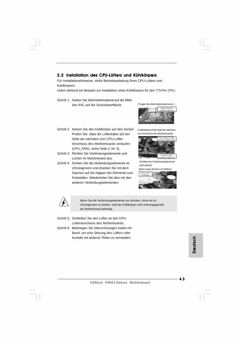
Schritt 1. Geben Sie Wärmeleitmaterial auf die Mittedes IHS, auf die Sockeloberfläche.
Schritt 2. Setzen Sie den Kühlkörper auf den Sockel.Prüfen Sie, dass die Lüfterkabel auf derSeite am nächsten zum CPU-Lüfter-Anschluss des Motherboards verlaufen(CPU_FAN1, siehe Seite 2, Nr. 5).
Schritt 3. Richten Sie Verbindungselemente undLöcher im Motherboard aus.
Schritt 4. Drehen Sie die Verbindungselemente imUhrzeigersinn und drücken Sie mit demDaumen auf die Kappen der Elemente zumFeststellen. Wiederholen Sie dies mit denanderen Verbindungselementen.
Wenn Sie die Verbindungselemente nur drücken, ohne sie imUhrzeigersinn zu drehen, wird der Kühlkörper nicht ordnungsgemäßam Motherboard befestigt.
Schritt 5. Schließen Sie den Lüfter an den CPU-Lüfteranschluss des Motherboards.
Schritt 6. Befestigen Sie überschüssiges Kabel mitBand, um eine Störung des Lüfters oderKontakt mit anderen Teilen zu vermeiden.
(Tragen Sie Wärmeleitmaterial auf. )
(Lüfterkabel auf der Seite am nächstenzum Anschluss des Motherboards)
(Schlitze der Verbindungselementenach außen)
(Nach unten drücken (4 Stellen))
De
uts
ch
De
uts
ch
De
uts
ch
De
uts
ch
De
uts
ch

4 44 44 44 44 4ASRock P45X3 Deluxe Motherboard
De
utsc
hD
eu
tsch
De
utsc
hD
eu
tsch
De
utsc
h
2.3 Installation der Speichermodule (DIMM)2.3 Installation der Speichermodule (DIMM)2.3 Installation der Speichermodule (DIMM)2.3 Installation der Speichermodule (DIMM)2.3 Installation der Speichermodule (DIMM)Die Motherboards P45X3 Deluxe bieten vier 240-pol. DDR3 (Double Data Rate 3)DIMM-Steckplätze und unterstützen die Dual-Kanal-Speichertechnologie. Für dieDual-Kanalkonfiguration dürfen Sie nur identische (gleiche Marke,Geschwindigkeit, Größe und gleicher Chiptyp) DDR3 DIMM-Paare in denSteckplätzen gleicher Farbe installieren. Mit anderen Worten, sie müssen einidentisches DDR3 DIMM-Paar im Dual-Kanal A (DDR3_A1 und DDR3_B1; blauSteckplätze, siehe Seite 2 Nr. 6) oder ein identisches DDR3 DIMM-Paar im Dual-Kanal B (DDR3_A2 und DDR3_B2; weiß Steckplätze, siehe Seite 2 Nr. 7)installieren, damit die Dual-Kanal-Speichertechnologie aktiviert werden kann. Aufdiesem Motherboard können Sie auch vier DDR3 DIMMs für eine Dual-Kanalkonfiguration installieren. Auf diesem Motherboard können Sie auch vierDDR3 DIMM-Module für eine Dual-Kanalkonfiguration installieren, wobei Sie bitte inallen vier Steckplätzen identische DDR3 DIMM-Module installieren. Beziehen Siesich dabei auf die nachstehende Konfigurationstabelle für Dual-Kanalspeicher.
Dual-Kanal-Speicherkonfigurationen
DDR3_A1 DDR3_A2 DDR3_B1 DDR3_B2(blau) (weiß) (blau) (weiß)
(1) Bestückt - Bestückt -(2) - Bestückt - Bestückt(3) Bestückt Bestückt Bestückt Bestückt
* Für Konfiguration (3) installieren Sie bitte identische DDR3 DIMMs in allen vier
• Steckplätzen.
1. Wenn Sie zwei Speichermodule installieren möchten, verwenden Siedazu für optimale Kompatibilität und Stabilität Steckplätze gleicherFarbe. Installieren Sie die beiden Speichermodule also entweder inden blau Steckplätzen (DDR3_A1 und DDR3_B1) oder den orangeSteckplätzen (DDR3_A2 und DDR3_B2).
2. Wenn nur ein Speichermodul oder drei Speichermodule in den DDR3DIMM-Steckplätzen auf diesem Motherboard installiert sind, kann esdie Dual-Kanal-Speichertechnologie nicht aktivieren.
3. Ist ein Speichermodulpaar NICHT im gleichen “Dual-Kanal” installiert,z.B. ein Speichermodulpaar wird in DDR3_A1 und DDR3_A2installiert, kann es die Dual-Kanal-Speichertechnologie nichtaktivieren.
4. Es ist nicht zulässig, DDR oder DDR2 in einen DDR3 Steckplatz zuinstallieren; andernfalls könnten Motherboard und DIMMs beschädigtwerden.
5. Wenn Sie DDR3 1600-Speichermodule für dieses Motherboardübernehmen, wird empfohlen, sie in den DDR3_A1-Steckplätzen zuinstallieren.
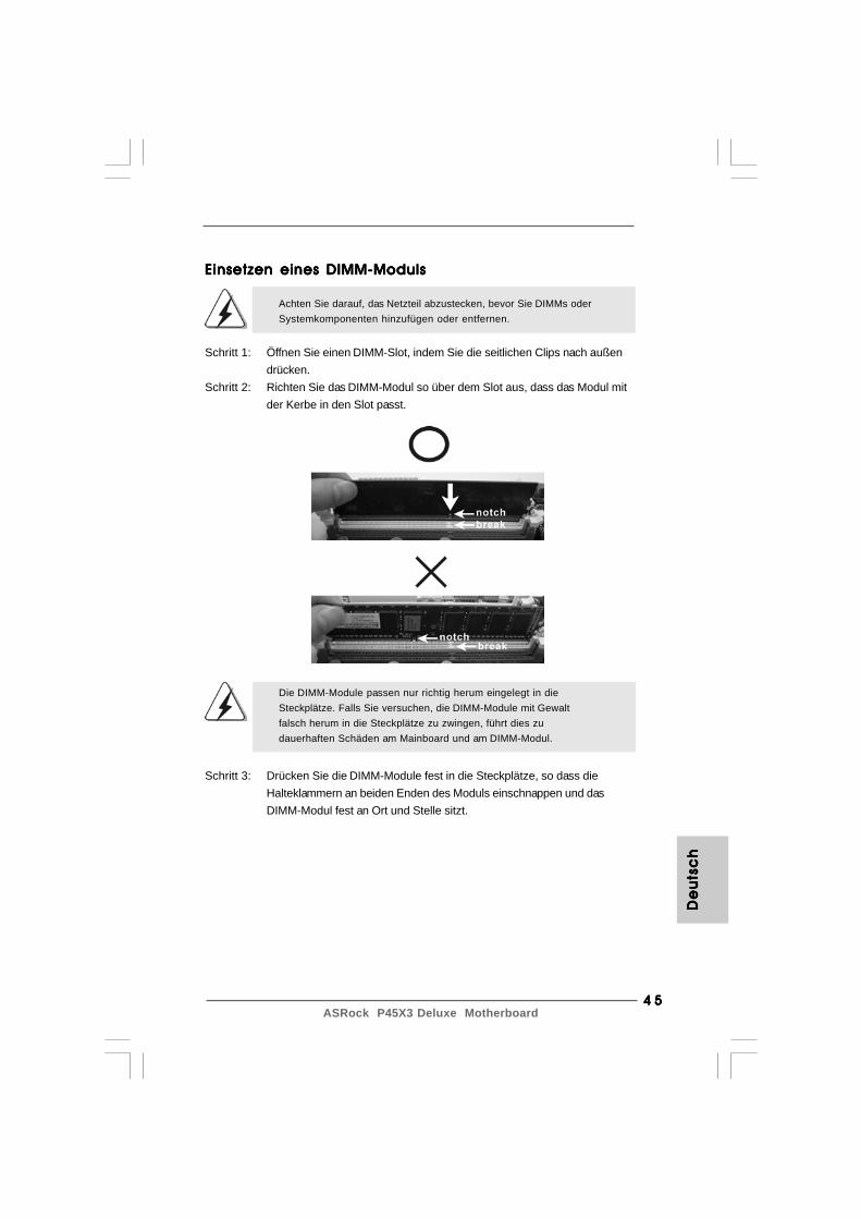
4 54 54 54 54 5ASRock P45X3 Deluxe Motherboard
De
uts
ch
De
uts
ch
De
uts
ch
De
uts
ch
De
uts
ch
Die DIMM-Module passen nur richtig herum eingelegt in dieSteckplätze. Falls Sie versuchen, die DIMM-Module mit Gewaltfalsch herum in die Steckplätze zu zwingen, führt dies zudauerhaften Schäden am Mainboard und am DIMM-Modul.
Schritt 3: Drücken Sie die DIMM-Module fest in die Steckplätze, so dass dieHalteklammern an beiden Enden des Moduls einschnappen und dasDIMM-Modul fest an Ort und Stelle sitzt.
Einsetzen eines DIMM-ModulsEinsetzen eines DIMM-ModulsEinsetzen eines DIMM-ModulsEinsetzen eines DIMM-ModulsEinsetzen eines DIMM-Moduls
Achten Sie darauf, das Netzteil abzustecken, bevor Sie DIMMs oderSystemkomponenten hinzufügen oder entfernen.
Schritt 1: Öffnen Sie einen DIMM-Slot, indem Sie die seitlichen Clips nach außendrücken.
Schritt 2: Richten Sie das DIMM-Modul so über dem Slot aus, dass das Modul mitder Kerbe in den Slot passt.
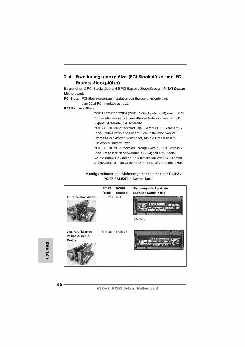
4 64 64 64 64 6ASRock P45X3 Deluxe Motherboard
De
utsc
hD
eu
tsch
De
utsc
hD
eu
tsch
De
utsc
h
2 .42 .42 .42 .42 .4 Erweiterungssteckplätze (PCI-Steckplätze und PCIErweiterungssteckplätze (PCI-Steckplätze und PCIErweiterungssteckplätze (PCI-Steckplätze und PCIErweiterungssteckplätze (PCI-Steckplätze und PCIErweiterungssteckplätze (PCI-Steckplätze und PCI
ExpressExpressExpressExpressExpress -Steckplätze)-Steckplätze)-Steckplätze)-Steckplätze)-Steckplätze)Es gibt einen 2 PCI-Steckplätze und 5 PCI Express-Steckplätze am P45X3 DeluxeMotherboard.PCI-Slots: PCI-Slots werden zur Installation von Erweiterungskarten mit
dem 32bit PCI-Interface genutzt.PCI Express-Slots:
PCIE1 / PCIE3 / PCIE4 (PCIE x1-Steckplatz; weiß) wird für PCIExpress-Karten mit x1 Lane-Breite-Karten verwendet, z.B.Gigabit LAN-Karte, SATA2-Karte.PCIE2 (PCIE x16-Steckplatz; blau) wird für PCI Express x16Lane-Breite-Grafikkarten oder für die Installation von PCIExpress-Grafikkarten verwendet, um die CrossFireXTM-Funktion zu unterstützen.PCIE5 (PCIE x16-Steckplatz; orange) wird für PCI Express x1Lane-Breite-Karten verwendet, z.B. Gigabit LAN-Karte,SATA2-Karte, etc., oder für die Installation von PCI Express-Grafikkarten, um die CrossFireXTM-Funktion zu unterstützen.
Konfigurationen des Sicherungssteckplatzes der PCIE2 /PCIE5 / SLI/XFire-Switch-Karte
PCIE2 PCIE5 Sicherungssteckplatz der (blau) (orange) SLI/XFire-Switch-Karte
Einzelne Grafikkarte PCIE x16 N/A
Zwei Grafikkarten PCIE x8 PCIE x8 im CrossFireXTM- Modus
(Default)
4 74 74 74 74 7ASRock P45X3 Deluxe Motherboard
1. Möchten Sie nur eine PCI Express-VGA-Karte auf diesem Motherboard installieren, dann installieren Sie sie bitte im PCIE2-Steckplatz (blau). In diesem Modus brauchen Sie die Standardeinstellung der ASRock SLI/XFire-Switch-Karte nicht zu ändern. Entfernen oder lockern Sie nicht die ASRock SLI/XFire-Switch-Karte, wenn sie sich noch im Betriebszustand befindet.2. Informationen über kompatible PCI Express-VGA-Karten im CrossFireXTM- Modus und CrossFireXTM-Konfigurationsabläufe finden Sie auf Seite 16 in der “CrossFireTM-Bedienungsanleitung”.
Einbau einer ErweiterungskarteEinbau einer ErweiterungskarteEinbau einer ErweiterungskarteEinbau einer ErweiterungskarteEinbau einer ErweiterungskarteSchritt 1: Bevor Sie die Erweiterungskarte installieren, vergewissern Sie sich,
dass das Netzteil ausgeschaltet und das Netzkabel abgezogen ist.Bitte lesen Sie die Dokumentation zur Erweiterungskarte und nehmenSie nötige Hardware-Einstellungen für die Karte vor, ehe Sie mit derInstallation beginnen.
Schritt 2: Entfernen Sie das Abdeckungsblech (Slotblende) von demGehäuseschacht (Slot) , den Sie nutzen möchten und behalten dieSchraube für den Einbau der Karte.
Schritt 3: Richten Sie die Karte über dem Slot aus und drücken Sie sie ohneGewalt hinein, bis sie den Steckplatz korrekt ausfüllt.
Schritt 4: Befestigen Sie die Karte mit der Schraube aus Schritt 2.
De
uts
ch
De
uts
ch
De
uts
ch
De
uts
ch
De
uts
ch
2.52.52.52.52.5 CrossFireXCrossFireXCrossFireXCrossFireXCrossFireXTMTMTMTMTM-Bedienungsanleitung-Bedienungsanleitung-Bedienungsanleitung-Bedienungsanleitung-BedienungsanleitungDiese Motherboard unterstützt die Funktion CrossFireXTM. CrossFireXTM-Technologie bietet die vorteilhaftesten Mittel, die für eine Kombination mehrererleistungsstarker Grafikprozessoren (GPU) auf einem einzelnen PC verfügbar sind.Durch Kombination einer Auswahl an unterschiedlichen Betriebsmodi mitintelligentem Softwaredesign und einem innovativen Verbindungsmechanismusermöglicht CrossFireXTM den höchstmöglichen Grad an Leistung und Bildqualität ineiner beliebigen 3D-Anwendung. Derzeit wird die Funktion CrossFireXTM vomBetriebssystem Windows® XP mit Service Pack 2 und VistaTM unterstützt.Besuchen Sie die AMD-Website, um sich über aktualisierte ATITM CrossFireXTM-Treiber zu informieren. Detaillierte Bedienschritte und kompatible PCI Express-Grafikkarten sind auf Seite 16.
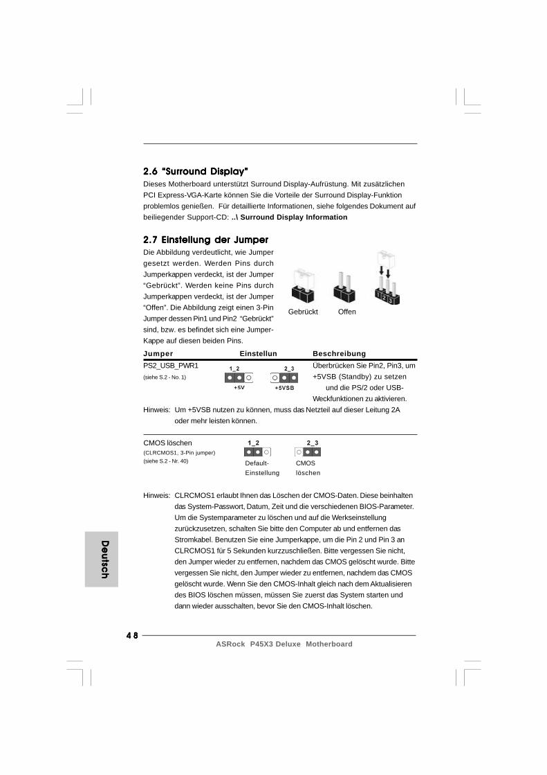
4 84 84 84 84 8ASRock P45X3 Deluxe Motherboard
Gebrückt Offen
2.7 Einstellung der Jumper2.7 Einstellung der Jumper2.7 Einstellung der Jumper2.7 Einstellung der Jumper2.7 Einstellung der JumperDie Abbildung verdeutlicht, wie Jumpergesetzt werden. Werden Pins durchJumperkappen verdeckt, ist der Jumper“Gebrückt”. Werden keine Pins durchJumperkappen verdeckt, ist der Jumper“Offen”. Die Abbildung zeigt einen 3-PinJumper dessen Pin1 und Pin2 “Gebrückt”sind, bzw. es befindet sich eine Jumper-Kappe auf diesen beiden Pins.
Jumper Einstellun BeschreibungPS2_USB_PWR1 Überbrücken Sie Pin2, Pin3, um(siehe S.2 - No. 1) +5VSB (Standby) zu setzen
und die PS/2 oder USB-Weckfunktionen zu aktivieren.
Hinweis: Um +5VSB nutzen zu können, muss das Netzteil auf dieser Leitung 2Aoder mehr leisten können.
CMOS löschen(CLRCMOS1, 3-Pin jumper)(siehe S.2 - Nr. 40)
Hinweis: CLRCMOS1 erlaubt Ihnen das Löschen der CMOS-Daten. Diese beinhaltendas System-Passwort, Datum, Zeit und die verschiedenen BIOS-Parameter.Um die Systemparameter zu löschen und auf die Werkseinstellungzurückzusetzen, schalten Sie bitte den Computer ab und entfernen dasStromkabel. Benutzen Sie eine Jumperkappe, um die Pin 2 und Pin 3 anCLRCMOS1 für 5 Sekunden kurzzuschließen. Bitte vergessen Sie nicht,den Jumper wieder zu entfernen, nachdem das CMOS gelöscht wurde. Bittevergessen Sie nicht, den Jumper wieder zu entfernen, nachdem das CMOSgelöscht wurde. Wenn Sie den CMOS-Inhalt gleich nach dem Aktualisierendes BIOS löschen müssen, müssen Sie zuerst das System starten unddann wieder ausschalten, bevor Sie den CMOS-Inhalt löschen.
CMOSlöschen
Default-Einstellung
2.6 “Surround Display”2.6 “Surround Display”2.6 “Surround Display”2.6 “Surround Display”2.6 “Surround Display”Dieses Motherboard unterstützt Surround Display-Aufrüstung. Mit zusätzlichenPCI Express-VGA-Karte können Sie die Vorteile der Surround Display-Funktionproblemlos genießen. Für detaillierte Informationen, siehe folgendes Dokument aufbeiliegender Support-CD: ..\ Surround Display Information
De
utsc
hD
eu
tsch
De
utsc
hD
eu
tsch
De
utsc
h

4 94 94 94 94 9ASRock P45X3 Deluxe Motherboard
Seriell-ATAII-Anschlüsse Diese sechs Serial ATAII-(SATAII_1: siehe S.2 - No. 14) (SATAII-)Verbínder(SATAII_2: siehe S.2 - No. 12) unterstützten SATA-Datenkabel(SATAII_3: siehe S.2 - No. 15) für interne(SATAII_4: siehe S.2 - No. 11) Massenspeichergeräte. Die(SATAII_5: siehe S.2 - No. 16) aktuelle SATAII-Schnittstelle(SATAII_6: siehe S.2 - No. 17) ermöglicht eine
Datenübertragungsrate bis3,0 Gb/s.
die rotgestreifte Seite auf Stift 1
2.8 Integrierte Header und Anschlüsse2.8 Integrierte Header und Anschlüsse2.8 Integrierte Header und Anschlüsse2.8 Integrierte Header und Anschlüsse2.8 Integrierte Header und Anschlüsse
Integrierte Header und Anschlüsse sind KEINE Jumper. Setzen Sie KEINEJumperkappen auf diese Header und Anschlüsse. Wenn Sie Jumperkappenauf Header und Anschlüsse setzen, wird das Motherboard unreparierbarbeschädigt!
Anschluss für dasFloppy-Laufwerk(33-Pin FLOPPY1)
(siehe S.2 - No. 27)
Hinweis: Achten Sie darauf, dass die rotgestreifte Seite des Kabel mit der Stift 1-Seite des Anschlusses verbunden wird.
Primärer IDE-Anschluss (blau)(39-pin IDE1, siehe S.2 - No. 9)
Blauer Anschluss Schwarzer Anschlusszum Motherboard zur Festplatte
80-adriges ATA 66/100/133 KabelHinweis: Details entnehmen Sie bitte den Anweisungen Ihres IDE-Gerätehändlers.
Serial ATA- (SATA-) SJedes Ende des SATADatenkabel Datenkabels kann an die SATA(Option) / SATAII Festplatte oder das
SATAII Verbindungsstück aufdieser Hauptplatineangeschlossen werden.
De
uts
ch
De
uts
ch
De
uts
ch
De
uts
ch
De
uts
ch
SATA
II_6
SATA
II_4
SATA
II_2
SATA
II_5
SATA
II_3
SATA
II_1
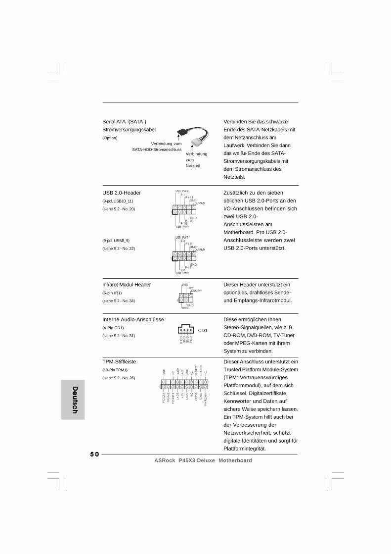
5 05 05 05 05 0ASRock P45X3 Deluxe Motherboard
Interne Audio-Anschlüsse Diese ermöglichen Ihnen(4-Pin CD1) Stereo-Signalquellen, wie z. B.(siehe S.2 - No. 31) CD-ROM, DVD-ROM, TV-Tuner
oder MPEG-Karten mit IhremSystem zu verbinden.
De
utsc
hD
eu
tsch
De
utsc
hD
eu
tsch
De
utsc
h
VerbindungzumNetzteil
Verbindung zumSATA-HDD-Stromanschluss
Serial ATA- (SATA-) Verbinden Sie das schwarzeStromversorgungskabel Ende des SATA-Netzkabels mit(Option) dem Netzanschluss am
Laufwerk. Verbinden Sie danndas weiße Ende des SATA-Stromversorgungskabels mitdem Stromanschluss desNetzteils.
USB 2.0-Header Zusätzlich zu den sieben(9-pol. USB10_11) üblichen USB 2.0-Ports an den(siehe S.2 - No. 20) I/O-Anschlüssen befinden sich
zwei USB 2.0-Anschlussleisten amMotherboard. Pro USB 2.0-
(9-pol. USB8_9) Anschlussleiste werden zwei(siehe S.2 - No. 22) USB 2.0-Ports unterstützt.
Infrarot-Modul-Header Dieser Header unterstützt ein(5-pin IR1) optionales, drahtloses Sende-(siehe S.2 - No. 34) und Empfangs-Infrarotmodul.
CD1
TPM-Stiftleiste Dieser Anschluss unterstützt ein(19-Pin TPM1) Trusted Platform Module-System(siehe S.2 - No. 26) (TPM: Vertrauenswürdiges
Plattformmodul), auf dem sichSchlüssel, Digitalzertifikate,Kennwörter und Daten aufsichere Weise speichern lassen.Ein TPM-System hilft auch beider Verbesserung derNetzwerksicherheit, schütztdigitale Identitäten und sorgt fürPlattformintegrität.

5 15 15 15 15 1ASRock P45X3 Deluxe Motherboard
Anschluss für Audio auf Dieses Interface zu einemder Gehäusevorderseite Audio-Panel auf der Vorderseite(9-Pin HD_AUDIO1) Ihres Gehäuses, ermöglicht(siehe S.2 - No. 29) Ihnen eine bequeme
Anschlussmöglichkeit undKontrolle über Audio-Geräte.
De
uts
ch
De
uts
ch
De
uts
ch
De
uts
ch
De
uts
ch
1. High Definition Audio unterstützt Jack Sensing (automatische Erkennung falsch angeschlossener Geräte), wobei jedoch die Bildschirmverdrahtung am Gehäuse HDA unterstützen muss, um richtig zu funktionieren. Beachten Sie bei der Installation im System die Anweisungen in unserem Handbuch und im Gehäusehandbuch.2. Wenn Sie die AC’97-Audioleiste verwenden, installieren Sie diese wie nachstehend beschrieben an der Front-Audioanschlussleiste: A. Schließen Sie Mic_IN (MIC) an MIC2_L an. B. Schließen Sie Audio_R (RIN) an OUT2_R und Audio_L (LIN) an OUT2_L an. C. Schließen Sie Ground (GND) an Ground (GND) an. D. MIC_RET und OUT_RET sind nur für den HD-Audioanschluss gedacht. Diese Anschlüsse müssen nicht an die AC’97-Audioleiste angeschlossen werden. E. Rufen Sie das BIOS-Setup-Dienstprogramm auf. Wechseln Sie zu Erweiterte Einstellungen und wählen Sie Chipset-Konfiguration. Setzen Sie die Option Frontleistenkontrolle von [Automatisch] auf [Aktiviert]. F. Rufen Sie das Windows-System auf. Klicken Sie auf das Symbol in der Taskleiste unten rechts, um den Realtek HD Audio-Manager aufzurufen. Für Windows® 2000 / XP / XP 64-Bit Betriebssystem: Klicken Sie auf “Audio-E/A”, wählen Sie die “Anschlusseinstellungen”
, wählen Sie “Erkennung der Frontleistenbuchse
deaktivieren” und speichern Sie die Änderung durch Klicken auf “OK”. Für Windows® VistaTM / VistaTM 64-Bit Betriebssystem: Die Rechtoberseite „Dateiordner“ Ikone anklicken ,
„Schalttafel Buchse Entdeckung sperren“ wählen und die Änderung speichern, indem Sie „OKAY“ klicken.
G. Aktivierung des vorderseitigen Mikrofons. Für Betriebssystem Windows® 2000 / XP / XP 64-Bit: Wählen Sie “Front Mic” (Vorderes Mikr.) als Standard-Aufnahmegerät. Möchten Sie Ihre Stimme über das vorderseitige Mikrofon hören, dann wählen Sie bitte das Symbol “Mute” (Stumm) unter “Front Mic” (Vorderes Mikr.) im Abschnitt “Playback” (Wiedergabe) ab. Für Betriebssystem Windows® VistaTM / VistaTM 64-Bit: Rufen Sie die Registerkarte “Front Mic” (Vorderes Mikr.) im Realtek-
Bedienfeld auf. Klicken Sie auf “Set Default Device” (Standardgerät einstellen), um das vorderseitige Mikrofon als Standard- Aufnahmegerät zu übernehmen.

5 25 25 25 25 2ASRock P45X3 Deluxe Motherboard
De
utsc
hD
eu
tsch
De
utsc
hD
eu
tsch
De
utsc
h
Obwohl dieses Motherboard einen vierpoligen CPU-Lüfteranschluss (QuietFan) bietet, können auch CPU-Lüfter mit dreipoligem Anschlussangeschlossen werden; auch ohne Geschwindigkeitsregulierung. Wenn Sieeinen dreipoligen CPU-Lüfter an den CPU-Lüferanschluss diesesMotherboards anschließen möchten, verbinden Sie ihn bitte mitden Pins 1 – 3.
Pins 1–3 anschließen
Lüfter mit dreipoligem Anschluss installieren
ATX-Netz-Header Verbinden Sie die ATX-(24-pin ATXPWR1) Stromversorgung mit diesem(siehe S.2 - No. 8) Header.
CPU-Lüfteranschluss Verbinden Sie das CPU -(4-pin CPU_FAN1) Lüfterkabel mit diesem(siehe S.2 - No. 5) Anschluss und passen Sie den
schwarzen Draht demErdungsstift an.
12
1
24
13
System Panel-Header Dieser Header unterstützt(9-pin PANEL1) mehrere Funktion der(siehe S.2 - No. 24) Systemvorderseite.
Gehäuselautsprecher-Header Schließen Sie den(4-pin SPEAKER1) Gehäuselautsprecher an(siehe S.2 - No. 25) diesen Header an.
Gehäuse-, Notebook- und Stromlüfteranschlüsse(4-pin CHA_FAN1)
(siehe S.2 - No. 13)
(3-pin NB_FAN1)
(siehe S.2 - No. 42)
(3-pin PWR_FAN1)
(siehe S.2 - No. 41)
Verbinden Sie die Lüfterkabel mitden Lüfteranschlüssen, wobeider schwarze Draht an denSchutzleiterstift angeschlossenwird.
4 3 2 1
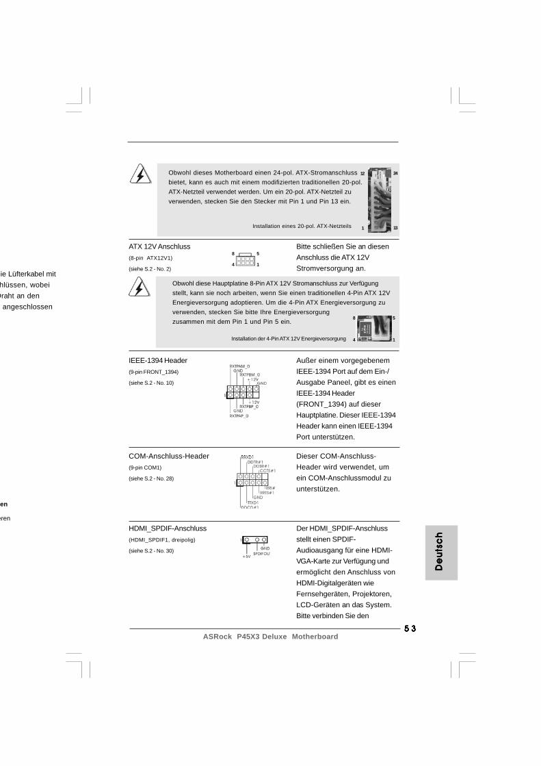
5 35 35 35 35 3ASRock P45X3 Deluxe Motherboard
Installation der 4-Pin ATX 12V Energieversorgung
Obwohl diese Hauptplatine 8-Pin ATX 12V Stromanschluss zur Verfügungstellt, kann sie noch arbeiten, wenn Sie einen traditionellen 4-Pin ATX 12VEnergieversorgung adoptieren. Um die 4-Pin ATX Energieversorgung zuverwenden, stecken Sie bitte Ihre Energieversorgungzusammen mit dem Pin 1 und Pin 5 ein.
en
eren
ATX 12V Anschluss Bitte schließen Sie an diesen(8-pin ATX12V1) Anschluss die ATX 12V(siehe S.2 - No. 2) Stromversorgung an.
Installation eines 20-pol. ATX-Netzteils
Obwohl dieses Motherboard einen 24-pol. ATX-Stromanschlussbietet, kann es auch mit einem modifizierten traditionellen 20-pol.ATX-Netzteil verwendet werden. Um ein 20-pol. ATX-Netzteil zuverwenden, stecken Sie den Stecker mit Pin 1 und Pin 13 ein.
12
1
24
13
De
uts
ch
De
uts
ch
De
uts
ch
De
uts
ch
De
uts
ch
ie Lüfterkabel mithlüssen, wobei
Draht an den angeschlossen
8 5
4 1
8 5
4 1
IEEE-1394 Header Außer einem vorgegebenem(9-pin FRONT_1394) IEEE-1394 Port auf dem Ein-/(siehe S.2 - No. 10) Ausgabe Paneel, gibt es einen
IEEE-1394 Header(FRONT_1394) auf dieserHauptplatine. Dieser IEEE-1394Header kann einen IEEE-1394Port unterstützen.
COM-Anschluss-Header Dieser COM-Anschluss-(9-pin COM1) Header wird verwendet, um(siehe S.2 - No. 28) ein COM-Anschlussmodul zu
unterstützen.
HDMI_SPDIF-Anschluss Der HDMI_SPDIF-Anschluss(HDMI_SPDIF1, dreipolig) stellt einen SPDIF-(siehe S.2 - No. 30) Audioausgang für eine HDMI-
VGA-Karte zur Verfügung undermöglicht den Anschluss vonHDMI-Digitalgeräten wieFernsehgeräten, Projektoren,LCD-Geräten an das System.Bitte verbinden Sie den
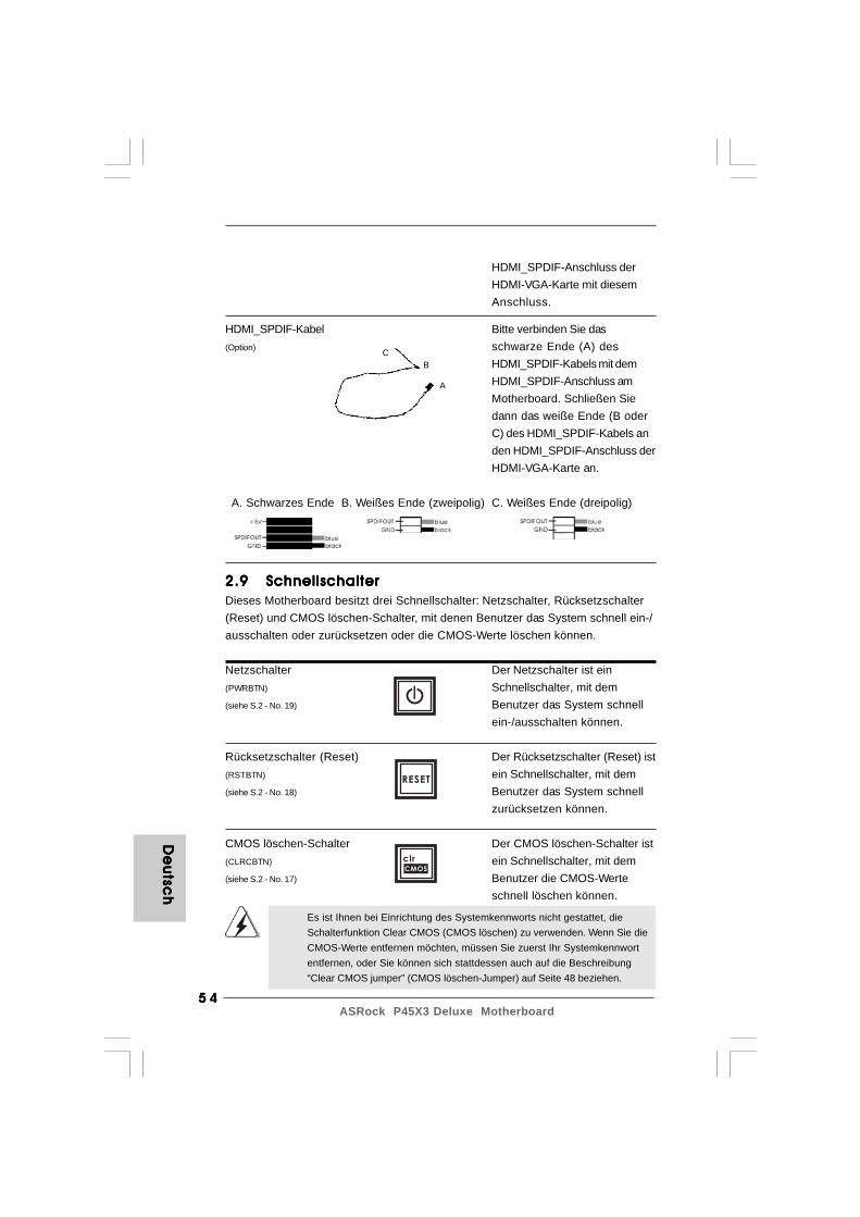
5 45 45 45 45 4ASRock P45X3 Deluxe Motherboard
De
utsc
hD
eu
tsch
De
utsc
hD
eu
tsch
De
utsc
h
CB
A
HDMI_SPDIF-Kabel Bitte verbinden Sie das(Option) schwarze Ende (A) des
HDMI_SPDIF-Kabels mit demHDMI_SPDIF-Anschluss amMotherboard. Schließen Siedann das weiße Ende (B oderC) des HDMI_SPDIF-Kabels anden HDMI_SPDIF-Anschluss derHDMI-VGA-Karte an.
A. Schwarzes Ende B. Weißes Ende (zweipolig) C. Weißes Ende (dreipolig)
HDMI_SPDIF-Anschluss derHDMI-VGA-Karte mit diesemAnschluss.
2.92.92.92.92.9 SchnellschalterSchnellschalterSchnellschalterSchnellschalterSchnellschalterDieses Motherboard besitzt drei Schnellschalter: Netzschalter, Rücksetzschalter(Reset) und CMOS löschen-Schalter, mit denen Benutzer das System schnell ein-/ausschalten oder zurücksetzen oder die CMOS-Werte löschen können.
Netzschalter Der Netzschalter ist ein(PWRBTN) Schnellschalter, mit dem(siehe S.2 - No. 19) Benutzer das System schnell
ein-/ausschalten können.
Rücksetzschalter (Reset) Der Rücksetzschalter (Reset) ist(RSTBTN) ein Schnellschalter, mit dem(siehe S.2 - No. 18) Benutzer das System schnell
zurücksetzen können.
CMOS löschen-Schalter Der CMOS löschen-Schalter ist(CLRCBTN) ein Schnellschalter, mit dem(siehe S.2 - No. 17) Benutzer die CMOS-Werte
schnell löschen können.
RESET
clr
CMOS
Es ist Ihnen bei Einrichtung des Systemkennworts nicht gestattet, dieSchalterfunktion Clear CMOS (CMOS löschen) zu verwenden. Wenn Sie dieCMOS-Werte entfernen möchten, müssen Sie zuerst Ihr Systemkennwortentfernen, oder Sie können sich stattdessen auch auf die Beschreibung“Clear CMOS jumper” (CMOS löschen-Jumper) auf Seite 48 beziehen.

5 55 55 55 55 5ASRock P45X3 Deluxe Motherboard
2.122.122.122.122.12 Windows Windows Windows Windows Windows®®®®® 2000 / XP / XP 64-Bit / Vista 2000 / XP / XP 64-Bit / Vista 2000 / XP / XP 64-Bit / Vista 2000 / XP / XP 64-Bit / Vista 2000 / XP / XP 64-Bit / VistaTMTMTMTMTM / Vista / Vista / Vista / Vista / VistaTMTMTMTMTM
64-Bit ohne RAID 64-Bit ohne RAID 64-Bit ohne RAID 64-Bit ohne RAID 64-Bit ohne RAID-F-F-F-F-Funktionalität installierenunktionalität installierenunktionalität installierenunktionalität installierenunktionalität installierenWenn Sie Windows® 2000 / XP / XP 64-Bit / VistaTM / VistaTM 64-Bit ohne RAID-Funktionalität auf Ihren SATA / SATAII-Festplatten installieren, dann folgen Sie bitte jenach dem zu installierenden Betriebssystem den folgenden Schritten.
Da der Windows® 2000 AHCI Treiber vom Chipsatz-Verkäufer nicht mitgeliefertwird, werden AHCI Funktionen unter Windows® 2000 nicht unterstützt.
2.112.112.112.112.11 TTTTTreiberinstallationreiberinstallationreiberinstallationreiberinstallationreiberinstallationZur Treiberinstallation Sie bitte die Unterstützungs-CD in Ihr optisches Laufwerkein. Anschließend werden die mit Ihrem System kompatiblen Treiber automatischerkannt und auf dem Bildschirm angezeigt. Zur Installation der nötigen Treibergehen Sie bitte der Reihe nach von oben nach unten vor. Nur so können die vonIhnen installierten Treiber richtig arbeiten.
Verwendung von SATA / SATAII-Festplatten ohne NCQ-Funktionen
SCHRITT 1: BIOS einrichten.A. Rufen Sie das BIOS SETUP UTILITY auf, wählen Sie den „Advanced“- Bildschirm (Erweitert), dann „IDE Configuration“ (IDE-Konfiguration).B. Stellen Sie “SATAII-Konfiguration” auf [Erweitert] ein, stellen Sie danach “SATAII konfigureren als” auf [IDE] ein.SCHRITT 2: Installieren Sie Windows® 2000 / XP / XP 64-Bit in Ihrem System.
2.12.1 Windows2.12.1 Windows2.12.1 Windows2.12.1 Windows2.12.1 Windows®®®®® 2000 / XP / XP 64-Bit ohne RAID- 2000 / XP / XP 64-Bit ohne RAID- 2000 / XP / XP 64-Bit ohne RAID- 2000 / XP / XP 64-Bit ohne RAID- 2000 / XP / XP 64-Bit ohne RAID-
Funktionalität installieren Funktionalität installieren Funktionalität installieren Funktionalität installieren Funktionalität installierenWenn Sie Windows® 2000 / XP / XP 64-Bit ohne RAID-Funktionalität auf Ihren SATA/ SATAII-Festplatten installieren, gehen Sie bitte wie folgt vor.
De
uts
ch
De
uts
ch
De
uts
ch
De
uts
ch
De
uts
ch
2.102.102.102.102.10 Debug-LEDDebug-LEDDebug-LEDDebug-LEDDebug-LEDDie integrierte Debug-LED liefert Codeinformationen, die eine Fehlerbehebungerleichtern. Siehe die Abbildungen auf den Seiten 28, 29 und 30 zum Ablesen derDebug-LED-Codes.

5 65 65 65 65 6ASRock P45X3 Deluxe Motherboard
Verwendung von SATA / SATAII-Festplatten mit NCQ-Funktionen
SCHRITT 1: BIOS einrichten.A. Rufen Sie das BIOS SETUP UTILITY auf, wählen Sie den „Advanced“- Bildschirm (Erweitert), dann „IDE Configuration“ (IDE-Konfiguration).B. Stellen Sie “SATAII-Konfiguration” auf [Erweitert] ein, stellen Sie danach “SATAII konfigureren als” auf [AHCI] ein.SCHRITT 2: Installieren Sie Windows® VistaTM / VistaTM 64-Bit in Ihrem System.Legen Sie Windows® VistaTM / VistaTM 64-Bit optische Disc in das optische Laufwerkein, um Ihr System zu starten. Folgen Sie anschließend den Anweisungen, um dasWindows® VistaTM / VistaTM 64-Bit Betriebssystem auf Ihrem System zu installieren.Wenn die Frage “Wo möchten Sie Windows installieren?” erscheint, legen Sie bittedie ASRock Support CD in Ihr optisches Laufwerk ein. Klicken Sie anschließend die“Treiber laden”-Schaltfläche links unten, um die Intel® AHCI-Treiber zu installieren. DieIntel® AHCI-Treiber befinden sich in dem folgenden Verzeichnis auf der Support CD:.. \ I386 (Für Windows® VistaTM-Benutzer).. \ AMD64 (Für Windows® VistaTM 64-Bit Benutzer)Legen Sie danach noch einmal die Windows® VistaTM / VistaTM 64-Bit optische Disc indas optische Laufwerk, um die Installation fortzusetzen.
SCHRITT 1: BIOS einrichten.A. Rufen Sie das BIOS SETUP UTILITY auf, wählen Sie den „Advanced“- Bildschirm (Erweitert), dann „IDE Configuration“ (IDE-Konfiguration).B. Stellen Sie “SATAII-Konfiguration” auf [Erweitert] ein, stellen Sie danach “SATAII konfigureren als” auf [IDE] ein.SCHRITT 2: Installieren Sie Windows® VistaTM / VistaTM 64-Bit in Ihrem System.
2.12.2 Windows2.12.2 Windows2.12.2 Windows2.12.2 Windows2.12.2 Windows®®®®® Vista Vista Vista Vista VistaTMTMTMTMTM / Vista / Vista / Vista / Vista / VistaTMTMTMTMTM 64-Bit ohne RAID- 64-Bit ohne RAID- 64-Bit ohne RAID- 64-Bit ohne RAID- 64-Bit ohne RAID-
Funktionalität installieren Funktionalität installieren Funktionalität installieren Funktionalität installieren Funktionalität installierenWenn Sie Windows® Vista
TM / Vista
TM 64-Bit ohne RAID-Funktionalität auf Ihren
SATA / SATAII-Festplatten installieren, gehen Sie bitte wie folgt vor.
Verwendung von SATA / SATAII-Festplatten ohne NCQ-Funktionen
De
utsc
hD
eu
tsch
De
utsc
hD
eu
tsch
De
utsc
h
5 75 75 75 75 7ASRock P45X3 Deluxe Motherboard
3. BIOS-Information3. BIOS-Information3. BIOS-Information3. BIOS-Information3. BIOS-InformationDas Flash Memory dieses Motherboards speichert das Setup-Utility. Drücken Sie<F2> während des POST (Power-On-Self-Test) um ins Setup zu gelangen, ansonstenwerden die Testroutinen weiter abgearbeitet. Wenn Sie ins Setup gelangen wollen,nachdem der POST durchgeführt wurde, müssen Sie das System über dieTastenkombination <Ctrl> + <Alt> + <Delete> oder den Reset-Knopf auf derGehäusevorderseite, neu starten. Natürlich können Sie einen Neustart auchdurchführen, indem Sie das System kurz ab- und danach wieder anschalten.Das Setup-Programm ist für eine bequeme Bedienung entwickelt worden. Es istein menügesteuertes Programm, in dem Sie durch unterschiedliche Untermenüsscrollen und die vorab festgelegten Optionen auswählen können. Für detaillierteInformationen zum BIOS-Setup, siehe bitte das Benutzerhandbuch (PDF Datei) aufder Support CD.
4. Sof4. Sof4. Sof4. Sof4. Software Supportware Supportware Supportware Supportware Support CD informationt CD informationt CD informationt CD informationt CD informationDieses Motherboard unterstützt eine Reiche von Microsoft® Windows®
Betriebssystemen: 2000 / XP / XP 64-Bit / VistaTM / VistaTM 64-Bit. Die IhremMotherboard beigefügte Support-CD enthält hilfreiche Software, Treiber undHilfsprogramme, mit denen Sie die Funktionen Ihres Motherboards verbessernkönnen Legen Sie die Support-CD zunächst in Ihr CD-ROM-Laufwerk ein. DerWillkommensbildschirm mit den Installationsmenüs der CD wird automatischaufgerufen, wenn Sie die “Autorun”-Funktion Ihres Systems aktiviert haben.Erscheint der Wilkommensbildschirm nicht, so “doppelklicken” Sie bitte auf das FileASSETUP.EXE im BIN-Verzeichnis der Support-CD, um die Menüs aufzurufen.Das Setup-Programm soll es Ihnen so leicht wie möglich machen. Es ist menügesteuert,d.h. Sie können in den verschiedenen Untermenüs Ihre Auswahl treffen und dieProgramme werden dann automatisch installiert.
De
uts
ch
De
uts
ch
De
uts
ch
De
uts
ch
De
uts
ch
2.132.132.132.132.13 Entkoppelte ÜbertaktungstechnologieEntkoppelte ÜbertaktungstechnologieEntkoppelte ÜbertaktungstechnologieEntkoppelte ÜbertaktungstechnologieEntkoppelte ÜbertaktungstechnologieDieses Motherboard unterstützt die Entkoppelte Übertaktungstechnologie, durchdie der FSB durch fixierte PCI- / PCIE- Busse beim Übertakten effektiver arbeiten.Bevor Sie die Entkoppelte Übertaktung aktivieren, stellen Sie bitte die Option“Overclock Mode” (Übertaktungsmodus) im BIOS von [Auto] auf [Manual] um. Dadurchwird der CPU-FSB beim Übertakten entkoppelt, PCI- / PCIE- Busse werden jedochfixiert, so dass der FSB in einer stabileren Übertaktungsumgebung arbeiten kann.
Beziehen Sie sich auf die Warnung vor möglichen Overclocking-Risiken aufSeite 37, bevor Sie die Untied Overclocking-Technologie anwenden.
5 85 85 85 85 8ASRock P45X3 Deluxe Motherboard
Fran
ça
isFra
nç
ais
Fran
ça
isFra
nç
ais
Fran
ça
is
1. Introduction1. Introduction1. Introduction1. Introduction1. IntroductionMerci pour votre achat d’une carte mère ASRock P45X3 Deluxe, une carte mère trèsfiable produite selon les critères de qualité rigoureux de ASRock. Elle offre desperformances excellentes et une conception robuste conformément à l’engagementd’ASRock sur la qualité et la fiabilité au long terme.Ce Guide d’installation rapide présente la carte mère et constitue un guided’installation pas à pas. Des informations plus détaillées concernant la carte mèrepourront être trouvées dans le manuel l’utilisateur qui se trouve sur le CD d’assistance.
Les spécifications de la carte mère et le BIOS ayant pu être mis àjour, le contenu de ce manuel est sujet à des changements sansnotification. Au cas où n’importe qu’elle modification intervenait sur cemanuel, la version mise à jour serait disponible sur le site webASRock sans nouvel avis. Vous trouverez les listes de prise encharge des cartes VGA et CPU également sur le site Web ASRock.Site web ASRock, http://www.asrock.comSi vous avez besoin de support technique en relation avec cette cartemère, veuillez consulter notre site Web pour de plus amplesinformations particulières au modèle que vous utilisez.www.asrock.com/support/index.asp
1.1 Contenu du paquet1.1 Contenu du paquet1.1 Contenu du paquet1.1 Contenu du paquet1.1 Contenu du paquetCarte mère ASRock P45X3 Deluxe
(Facteur de forme ATX: 12.0 pouces x 9.6 pouces, 30.5 cm x 24.4 cm)Guide d’installation rapide ASRock P45X3 DeluxeCD de soutien ASRock P45X3 DeluxeUne carte switch ASRock SLI/XFireUn câble ruban IDE Ultra ATA 66/100/133 80 conducteursUn câble ruban pour un lecteur de disquettes 3,5 poucesQuatre câbles de données de série ATA (SATA) (en option)Un câble d’alimentation de série ATA (SATA) HDD (en option)Un I/O Panel Shield
5 95 95 95 95 9ASRock P45X3 Deluxe Motherboard
1.21.21.21.21.2 SpécificationsSpécificationsSpécificationsSpécificationsSpécifications
Format - Facteur de forme ATX: 12.0 pouces x 9.6 pouces, 30.5 cm x 24.4 cm- Accessoires de Carte mère (condensateurs 100% polymère conducteur de haute qualité fabriqué au Japon)
CPU - LGA 775 pour Intel® CoreTM 2 Extreme / CoreTM 2 Quad / CoreTM 2 Duo / Pentium® Dual Core / Celeron® Dual Core / Celeron® acceptant les processeurs Penryn Quad Core Yorkfield et Dual Core Wolfdale
- Compatible avec FSB2000/1600/1333/1066/800 MHz(voir ATTENTION 1)
- Conception avancée V8 Power Phase- Prise en charge de la technologie Hyper-Threading (voir ATTENTION 2)- Prend en charge la technologie Untied Overclocking
(voir ATTENTION 3)- Prise en charge de la technologie EM64T par le CPU
Chipsets - Northbridge: Intel® P45- Southbridge: Intel® ICH10
Mémoire - Compatible avec la Technologie de Mémoire à Canal Double(voir ATTENTION 4)
- 4 x slots DIMM DDR3- Supporter DDR3 1600/1333/1066/800 non-ECC, sans amortissement mémoire (voir ATTENTION 5)- Capacité maxi de mémoire système: 16GB (voir ATTENTION 6)
Slot d’extension - 2 x slots PCI Express 2.0 x16 (bleu @ mode x16, orange @ mode x8)- 3 x slots PCI Express x1- 2 x slots PCI- Prend en charge ATITM CrossFireXTM (voir ATTENTION 7)
Audio - 7.1 Son haute définition de première qualité CH Windows®
VistaTM (codec audio ALC888) LAN - PCIE x1 Gigabit LAN 10/100/1000 Mb/s
- Realtek RTL8111DL- Support du Wake-On-LAN
Panneau arrière I/O Panel- 1 x port souris PS/2- 1 x port clavier PS/2- 1 x Port de sortie coaxial SPDIF
FFFF F ra
nra
nra
nra
nra
nç
ais
ça
isç
ais
ça
isç
ais

6 06 06 06 06 0ASRock P45X3 Deluxe Motherboard
Fran
ça
isFra
nç
ais
Fran
ça
isFra
nç
ais
Fran
ça
is
- 1 x Port de sortie optique SPDIF- 1 x port IEEE 1394- 7 x ports USB 2.0 par défaut- 1 x Connecteur eSATAII/USB alimenté- 1 x port LAN RJ-45 avec LED (ACT/LED CLIGNOTANTE et LED VITESSE)- 1 x interrupteur d’effacement du CMOS avec LED- Prise HD Audio: Haut-parleur latéral / Haut-parleur arrière / Central /Basses / Entrée Ligne / Haut-parleur frontal / Microphone (voir ATTENTION 8)
Connecteurs - 6 x connecteurs SATAII, prennent en charge un taux de transfert de données pouvant aller jusqu’à 3.0Go/s, supporte NCQ, AHCI et “Hot-Plug” (Connexion à chaud) (voir ATTENTION 9)- 1 x ATA133 IDE connecteurs (prend en charge jusqu’à 2 périphériques IDE)- 1 x Port Disquette- 1 x En-tête du module infrarouge- 1 x En-tête de port COM- 1 x Connecteur HDMI_SPDIF- 1 x Connecteur IEEE 1394- 1 x connecteur TPM- Connecteur pour processeur/châssis/NB/ventilateur- br. 24 connecteur d’alimentation ATX- br. 8 connecteur d’alimentation 12V ATX- Connecteurs audio internes- Connecteur audio panneau avant- 2 x En-tête USB 2.0 (prendre en charge 4 ports USB 2.0 supplémentaires) (voir ATTENTION 10)
Interrupteur - 1 x interrupteur d’effacement du CMOS avec LED rapide - 1 x interrupteur d’alimentation avec LED
- 1 x interrupteur de réinitialisation avec LED BIOS - 8Mb BIOS AMI
- BIOS AMI- Support du “Plug and Play”- Compatible pour événements de réveil ACPI 1.1- Gestion jumperless- Support SMBIOS 2.3.1- CPU, VCCM, VTT Tension Multi-ajustement- Supporter I. O. T. (Technologie d’Overclocking Intelligent)- Prise en charge du Smart BIOS
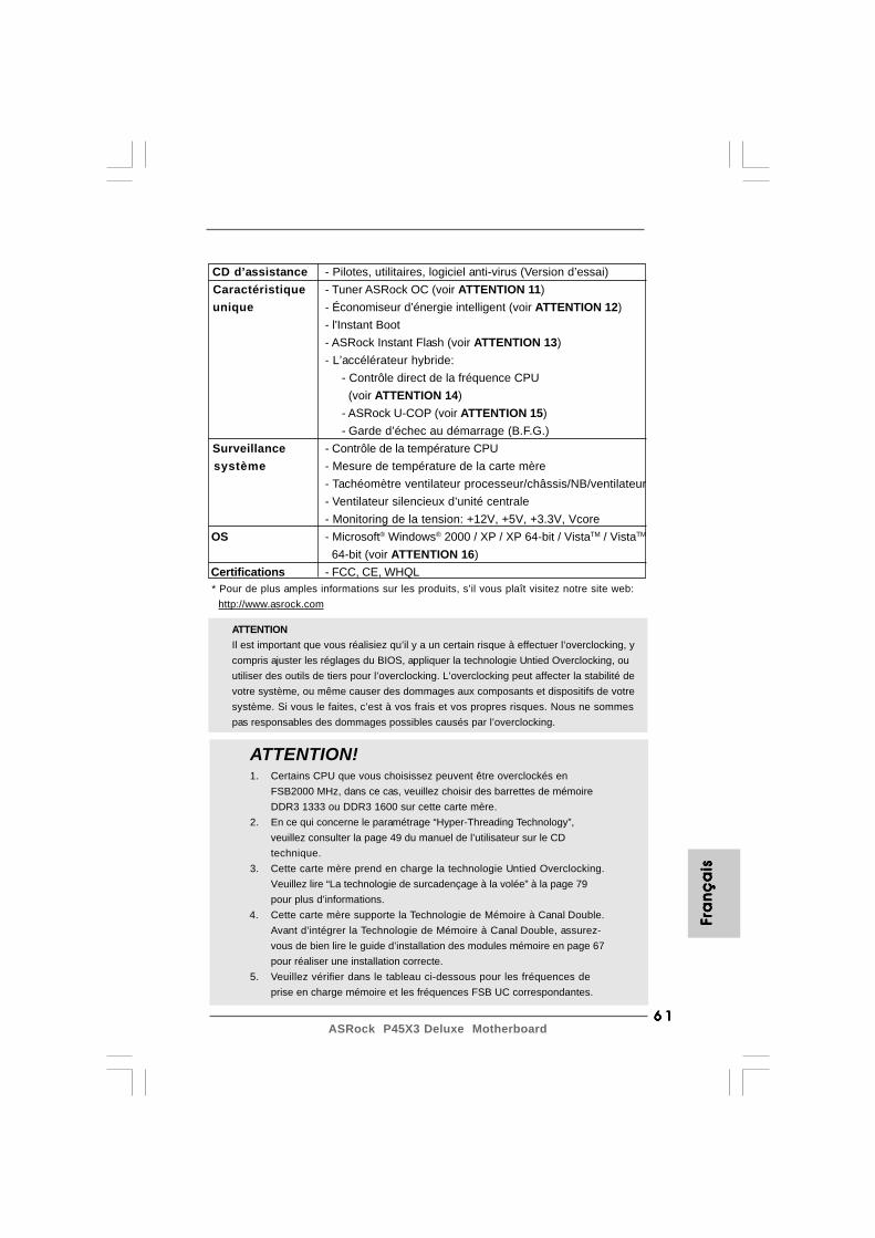
6 16 16 16 16 1ASRock P45X3 Deluxe Motherboard
ATTENTIONIl est important que vous réalisiez qu’il y a un certain risque à effectuer l’overclocking, ycompris ajuster les réglages du BIOS, appliquer la technologie Untied Overclocking, ouutiliser des outils de tiers pour l’overclocking. L’overclocking peut affecter la stabilité devotre système, ou même causer des dommages aux composants et dispositifs de votresystème. Si vous le faites, c’est à vos frais et vos propres risques. Nous ne sommespas responsables des dommages possibles causés par l’overclocking.
FFFF F ra
nra
nra
nra
nra
nç
ais
ça
isç
ais
ça
isç
ais
CD d’assistance - Pilotes, utilitaires, logiciel anti-virus (Version d’essai) Caractéristique - Tuner ASRock OC (voir ATTENTION 11) unique - Économiseur d’énergie intelligent (voir ATTENTION 12)
- l'Instant Boot- ASRock Instant Flash (voir ATTENTION 13)- L’accélérateur hybride:
- Contrôle direct de la fréquence CPU (voir ATTENTION 14)- ASRock U-COP (voir ATTENTION 15)- Garde d’échec au démarrage (B.F.G.)
Surveillance - Contrôle de la température CPU système - Mesure de température de la carte mère
- Tachéomètre ventilateur processeur/châssis/NB/ventilateur- Ventilateur silencieux d’unité centrale- Monitoring de la tension: +12V, +5V, +3.3V, Vcore
OS - Microsoft® Windows® 2000 / XP / XP 64-bit / VistaTM / VistaTM
64-bit (voir ATTENTION 16) Certifications - FCC, CE, WHQL * Pour de plus amples informations sur les produits, s’il vous plaît visitez notre site web: http://www.asrock.com
ATTENTION!1. Certains CPU que vous choisissez peuvent être overclockés en
FSB2000 MHz, dans ce cas, veuillez choisir des barrettes de mémoireDDR3 1333 ou DDR3 1600 sur cette carte mère.
2. En ce qui concerne le paramétrage “Hyper-Threading Technology”,veuillez consulter la page 49 du manuel de l’utilisateur sur le CDtechnique.
3. Cette carte mère prend en charge la technologie Untied Overclocking.Veuillez lire “La technologie de surcadençage à la volée” à la page 79pour plus d’informations.
4. Cette carte mère supporte la Technologie de Mémoire à Canal Double.Avant d’intégrer la Technologie de Mémoire à Canal Double, assurez-vous de bien lire le guide d’installation des modules mémoire en page 67pour réaliser une installation correcte.
5. Veuillez vérifier dans le tableau ci-dessous pour les fréquences deprise en charge mémoire et les fréquences FSB UC correspondantes.
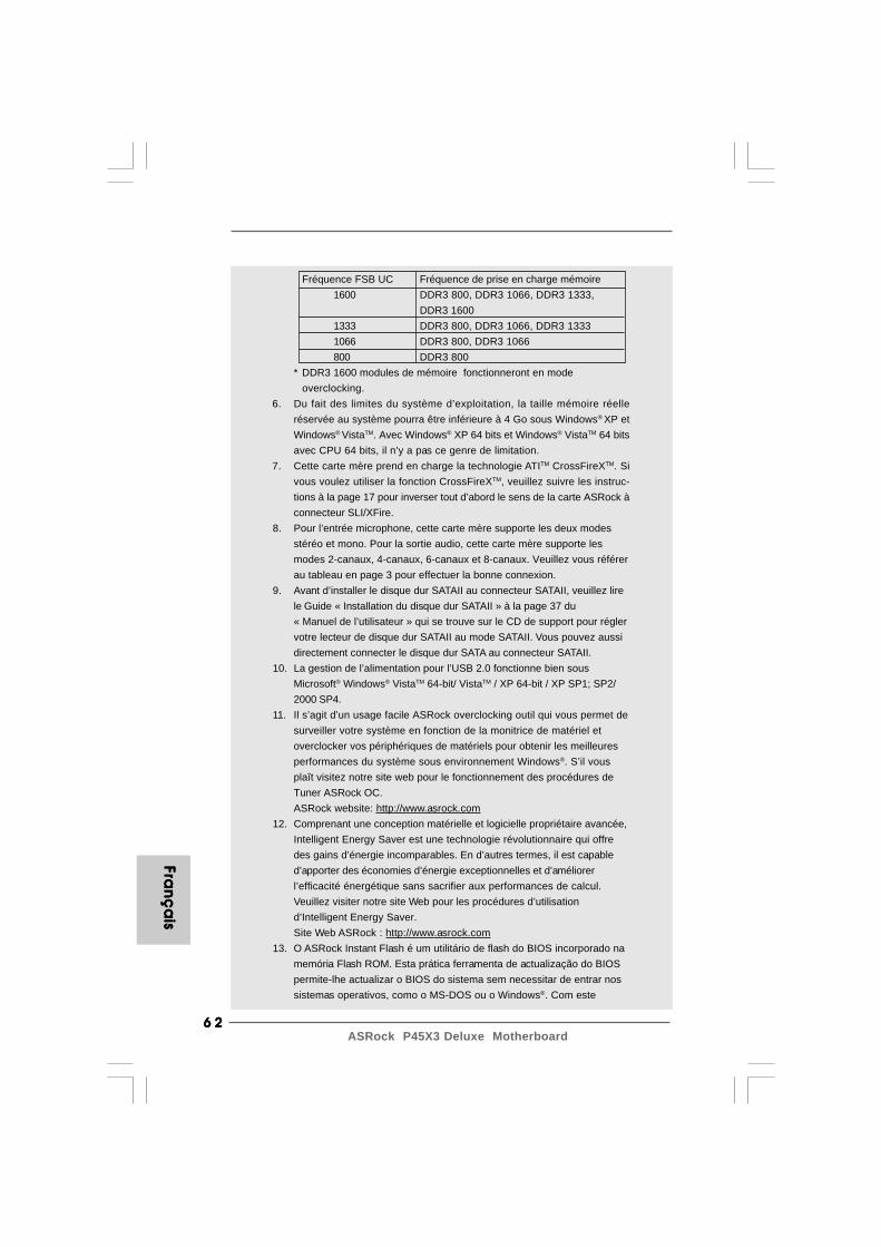
6 26 26 26 26 2ASRock P45X3 Deluxe Motherboard
Fran
ça
isFra
nç
ais
Fran
ça
isFra
nç
ais
Fran
ça
is
Fréquence FSB UC Fréquence de prise en charge mémoire1600 DDR3 800, DDR3 1066, DDR3 1333,
DDR3 16001333 DDR3 800, DDR3 1066, DDR3 13331066 DDR3 800, DDR3 1066800 DDR3 800
* DDR3 1600 modules de mémoire fonctionneront en modeoverclocking.
6. Du fait des limites du système d’exploitation, la taille mémoire réelleréservée au système pourra être inférieure à 4 Go sous Windows® XP etWindows® VistaTM. Avec Windows® XP 64 bits et Windows® VistaTM 64 bitsavec CPU 64 bits, il n’y a pas ce genre de limitation.
7. Cette carte mère prend en charge la technologie ATITM CrossFireXTM. Sivous voulez utiliser la fonction CrossFireXTM, veuillez suivre les instruc-tions à la page 17 pour inverser tout d’abord le sens de la carte ASRock àconnecteur SLI/XFire.
8. Pour l’entrée microphone, cette carte mère supporte les deux modesstéréo et mono. Pour la sortie audio, cette carte mère supporte lesmodes 2-canaux, 4-canaux, 6-canaux et 8-canaux. Veuillez vous référerau tableau en page 3 pour effectuer la bonne connexion.
9. Avant d’installer le disque dur SATAII au connecteur SATAII, veuillez lirele Guide « Installation du disque dur SATAII » à la page 37 du« Manuel de l’utilisateur » qui se trouve sur le CD de support pour réglervotre lecteur de disque dur SATAII au mode SATAII. Vous pouvez aussidirectement connecter le disque dur SATA au connecteur SATAII.
10. La gestion de l’alimentation pour l’USB 2.0 fonctionne bien sousMicrosoft® Windows® VistaTM 64-bit/ VistaTM / XP 64-bit / XP SP1; SP2/2000 SP4.
11. Il s’agit d’un usage facile ASRock overclocking outil qui vous permet desurveiller votre système en fonction de la monitrice de matériel etoverclocker vos périphériques de matériels pour obtenir les meilleuresperformances du système sous environnement Windows®. S’il vousplaît visitez notre site web pour le fonctionnement des procédures deTuner ASRock OC.ASRock website: http://www.asrock.com
12. Comprenant une conception matérielle et logicielle propriétaire avancée,Intelligent Energy Saver est une technologie révolutionnaire qui offredes gains d’énergie incomparables. En d’autres termes, il est capabled’apporter des économies d’énergie exceptionnelles et d’améliorerl’efficacité énergétique sans sacrifier aux performances de calcul.Veuillez visiter notre site Web pour les procédures d’utilisationd’Intelligent Energy Saver.Site Web ASRock : http://www.asrock.com
13. O ASRock Instant Flash é um utilitário de flash do BIOS incorporado namemória Flash ROM. Esta prática ferramenta de actualização do BIOSpermite-lhe actualizar o BIOS do sistema sem necessitar de entrar nossistemas operativos, como o MS-DOS ou o Windows®. Com este

6 36 36 36 36 3ASRock P45X3 Deluxe Motherboard
2. Installation2. Installation2. Installation2. Installation2. Installation
Précautions à observer avant l’installationPrécautions à observer avant l’installationPrécautions à observer avant l’installationPrécautions à observer avant l’installationPrécautions à observer avant l’installationVeuillez tenir compte des précautions suivantes avant l’installationdes composants ou tout réglage de la carte mère.
1. Débranchez le câble d’alimentation de la prise secteur avant de toucherà tout composant. En ne le faisant pas, vous pouvez sérieusementendommager la carte mère, les périphériques et/ou les composants.
2. Pour éviter d’endommager les composants de la carte mère du fait del’électricité statique, ne posez JAMAIS votre carte mère directement surde la moquette ou sur un tapis. N’oubliez pas d’utiliser un braceletantistatique ou de toucher un objet relié à la masse avant de manipulerles composants.
3. Tenez les composants par les bords et ne touchez pas les circuitsintégrés.
4. A chaque désinstallation de composant, placez-le sur un supportantistatique ou dans son sachet d’origine.
5. Lorsque vous placez les vis dans les orifices pour vis pour fixer la cartemère sur le châssis, ne serrez pas trop les vis ! Vous risquez sinond’endommager la carte mère.
FFFF F ra
nra
nra
nra
nra
nç
ais
ça
isç
ais
ça
isç
ais
utilitário, poderá premir a tecla <F6> durante o teste de arranque POSTou premir a tecla <F2> para exibir o menu de configuração do BIOSpara aceder ao ASRock Instant Flash. Execute esta ferramenta paraguardar o novo ficheiro de BIOS numa unidade flash USB, numadisquete ou num disco rígido, em seguida, poderá actualizar o BIOScom apenas alguns cliques sem ter de utilizar outra disquete ou outrocomplicado utilitário de flash. Note que a unidade flash USB ou aunidade de disco rígido devem utilizar o sistema de ficheiros FAT32/16/12.
14. Même si cette carte mère offre un contrôle sans souci, il n’est pasrecommandé d’y appliquer un over clocking. Des fréquences de bus CPUautres que celles recommandées risquent de rendre le système instableou d’endommager le CPU et la carte mère.
15. Lorsqu’une surchauffe du CPU est détectée, le système s’arrêteautomatiquement. Avant de redémarrer le système, veuillez vérifier quele ventilateur d’UC sur la carte mère fonctionne correctement et débranchezle cordon d’alimentation, puis rebranchez-le. Pour améliorer la dissipationde la chaleur, n’oubliez pas de mettre de la pâte thermique entre le CPU ledissipateur lors de l’installation du PC.
16. Les fonctions AHCI ne sont pas Supporté sous Windows® 2000 OS. Il estrecommandé d’utiliser le mode IDE sous Windows® 2000. Veuillez con-sulter la page 59 du “Guide d’utilisation” dans le CD de support pour ledétail des réglages.
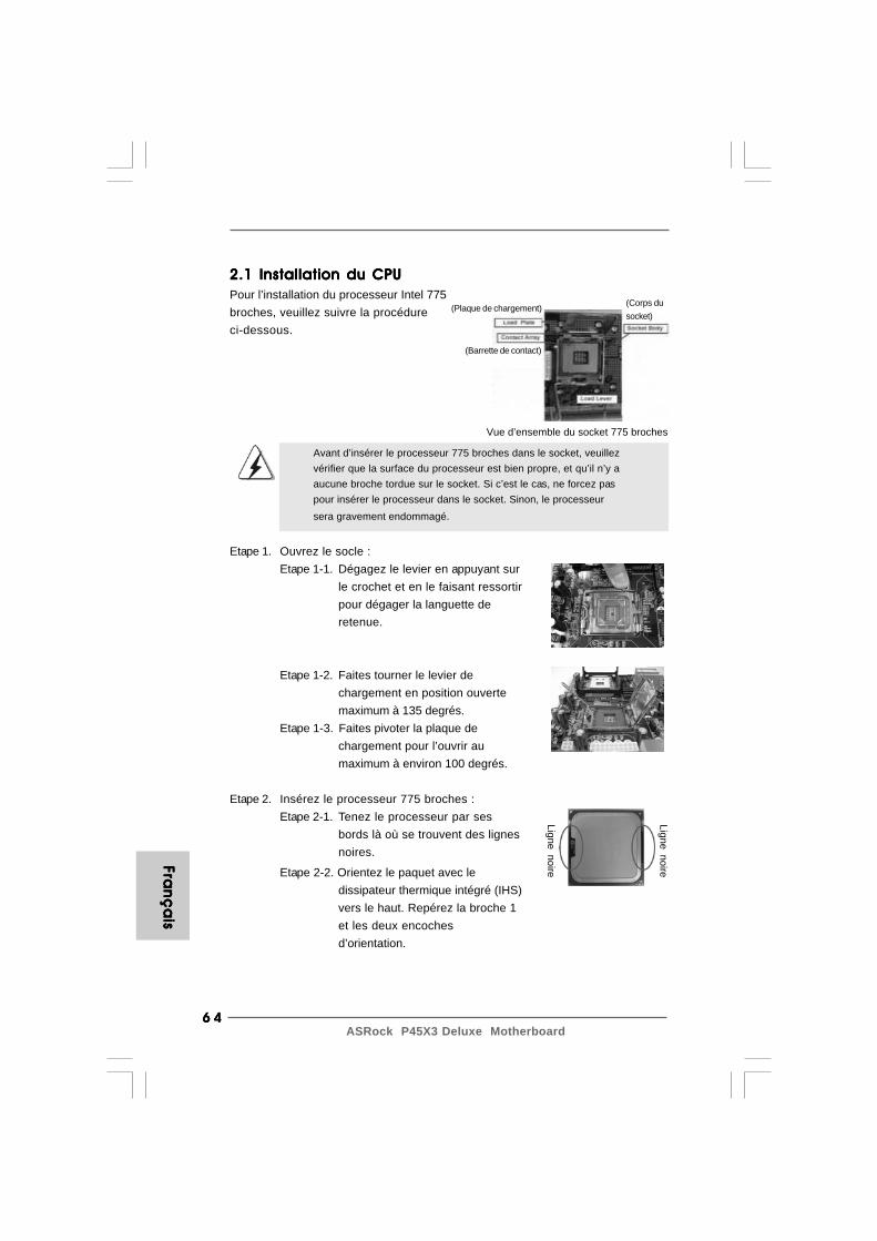
6 46 46 46 46 4ASRock P45X3 Deluxe Motherboard
Fran
ça
isFra
nç
ais
Fran
ça
isFra
nç
ais
Fran
ça
is
2.1 Installation du CPU2.1 Installation du CPU2.1 Installation du CPU2.1 Installation du CPU2.1 Installation du CPUPour l’installation du processeur Intel 775broches, veuillez suivre la procédureci-dessous.
Avant d’insérer le processeur 775 broches dans le socket, veuillezvérifier que la surface du processeur est bien propre, et qu’il n’y aaucune broche tordue sur le socket. Si c’est le cas, ne forcez paspour insérer le processeur dans le socket. Sinon, le processeursera gravement endommagé.
Etape 1. Ouvrez le socle :Etape 1-1. Dégagez le levier en appuyant sur
le crochet et en le faisant ressortirpour dégager la languette deretenue.
Etape 1-2. Faites tourner le levier dechargement en position ouvertemaximum à 135 degrés.
Etape 1-3. Faites pivoter la plaque dechargement pour l’ouvrir aumaximum à environ 100 degrés.
Etape 2. Insérez le processeur 775 broches :Etape 2-1. Tenez le processeur par ses
bords là où se trouvent des lignesnoires.
Vue d’ensemble du socket 775 broches
Ligne noire
(Plaque de chargement)
(Barrette de contact)
(Corps dusocket)
Ligne noireEtape 2-2. Orientez le paquet avec ledissipateur thermique intégré (IHS)vers le haut. Repérez la broche 1et les deux encochesd’orientation.

6 56 56 56 56 5ASRock P45X3 Deluxe Motherboard
Pour une insertion correcte, veuillez vérifier que vous faites biencorrespondre les deux encoches d’orientation sur le processeuravec les deux détrompeurs du socket.
Etape 2-3. Mettez soigneusement en place leprocesseur dans le socle en unmouvement strictement vertical.
Etape 2-4. Vérifiez que le processeur estbien installé dans le socle et queles encoches d’orientation sontdans la bonne position.
Etape 3. Enlevez le capuchon PnP (Pick et Place) :De l’index et du de votre main gauche,soutenez le bord de la plaque dechargement, engagez le PnP avec le poucede votre main droite, et enlevez le capuchondu socle tout en appuyant sur le centre ducapuchon PnP pour vous aider.
1. Il est recommandé d’utiliser la languette du capuchon ; évitez de faire sortir le capuchon PnP.2. Ce capuchon doit être mis en place si vous renvoyez la carte mère pour service après vente.
Etape 4. Refermez le socle :Etape 4-1. Faites pivoter la plaque de
chargement sur l’IHS.Etape 4-2. Tout en appuyant doucement sur
la plaque de chargement, engagezle levier de chargement
Processeur 775 broches
Socket 775 broches
Détrompeur Détrompeur
broche 1
Encoched’orientation
Encoched’orientation
broche 1
Etape 4-3. Fixez le levier de chargementavec la languette de la plaque dechargement sous la languette deretenue du levier de chargement.
FFFF F ra
nra
nra
nra
nra
nç
ais
ça
isç
ais
ça
isç
ais
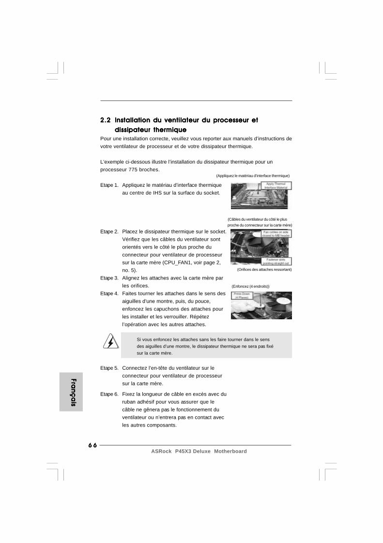
6 66 66 66 66 6ASRock P45X3 Deluxe Motherboard
Fran
ça
isFra
nç
ais
Fran
ça
isFra
nç
ais
Fran
ça
is
2.22.22.22.22.2 Installation du ventilateur du processeur etInstallation du ventilateur du processeur etInstallation du ventilateur du processeur etInstallation du ventilateur du processeur etInstallation du ventilateur du processeur et
dissipateur thermiquedissipateur thermiquedissipateur thermiquedissipateur thermiquedissipateur thermiquePour une installation correcte, veuillez vous reporter aux manuels d’instructions devotre ventilateur de processeur et de votre dissipateur thermique.
L’exemple ci-dessous illustre l’installation du dissipateur thermique pour unprocesseur 775 broches.
Etape 1. Appliquez le matériau d’interface thermiqueau centre de IHS sur la surface du socket.
Etape 2. Placez le dissipateur thermique sur le socket.Vérifiez que les câbles du ventilateur sontorientés vers le côté le plus proche duconnecteur pour ventilateur de processeursur la carte mère (CPU_FAN1, voir page 2,no. 5).
Etape 3. Alignez les attaches avec la carte mère parles orifices.
Etape 4. Faites tourner les attaches dans le sens desaiguilles d’une montre, puis, du pouce,enfoncez les capuchons des attaches pourles installer et les verrouiller. Répétezl’opération avec les autres attaches.
Si vous enfoncez les attaches sans les faire tourner dans le sensdes aiguilles d’une montre, le dissipateur thermique ne sera pas fixésur la carte mère.
Etape 5. Connectez l’en-tête du ventilateur sur leconnecteur pour ventilateur de processeursur la carte mère.
(Appliquez le matériau d’interface thermique)
(Câbles du ventilateur du côté le plusproche du connecteur sur la carte mère)
(Orifices des attaches ressortant)
(Enfoncez (4 endroits))
Etape 6. Fixez la longueur de câble en excès avec duruban adhésif pour vous assurer que lecâble ne gênera pas le fonctionnement duventilateur ou n’entrera pas en contact avecles autres composants.
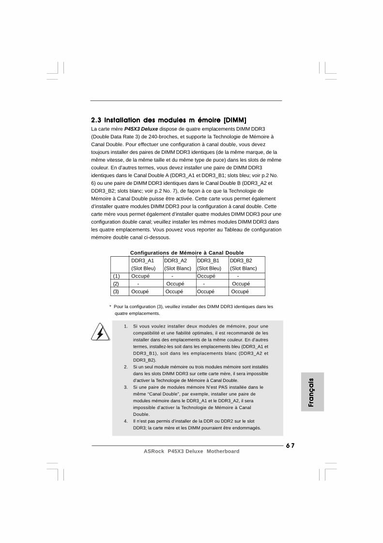
6 76 76 76 76 7ASRock P45X3 Deluxe Motherboard
1. Si vous voulez installer deux modules de mémoire, pour unecompatibilité et une fiabilité optimales, il est recommandé de lesinstaller dans des emplacements de la même couleur. En d’autrestermes, installez-les soit dans les emplacements bleu (DDR3_A1 etDDR3_B1), soit dans les emplacements blanc (DDR3_A2 etDDR3_B2).
2. Si un seul module mémoire ou trois modules mémoire sont installésdans les slots DIMM DDR3 sur cette carte mère, il sera impossibled’activer la Technologie de Mémoire à Canal Double.
3. Si une paire de modules mémoire N’est PAS installée dans lemême “Canal Double”, par exemple, installer une paire demodules mémoire dans le DDR3_A1 et le DDR3_A2, il seraimpossible d’activer la Technologie de Mémoire à CanalDouble.
4. Il n’est pas permis d’installer de la DDR ou DDR2 sur le slotDDR3; la carte mère et les DIMM pourraient être endommagés.
FFFF F ra
nra
nra
nra
nra
nç
ais
ça
isç
ais
ça
isç
ais
2.3 Installation des modules m émoire [DIMM]2.3 Installation des modules m émoire [DIMM]2.3 Installation des modules m émoire [DIMM]2.3 Installation des modules m émoire [DIMM]2.3 Installation des modules m émoire [DIMM]La carte mère P45X3 Deluxe dispose de quatre emplacements DIMM DDR3(Double Data Rate 3) de 240-broches, et supporte la Technologie de Mémoire àCanal Double. Pour effectuer une configuration à canal double, vous deveztoujours installer des paires de DIMM DDR3 identiques (de la même marque, de lamême vitesse, de la même taille et du même type de puce) dans les slots de mêmecouleur. En d’autres termes, vous devez installer une paire de DIMM DDR3identiques dans le Canal Double A (DDR3_A1 et DDR3_B1; slots bleu; voir p.2 No.6) ou une paire de DIMM DDR3 identiques dans le Canal Double B (DDR3_A2 etDDR3_B2; slots blanc; voir p.2 No. 7), de façon à ce que la Technologie deMémoire à Canal Double puisse être activée. Cette carte vous permet égalementd’installer quatre modules DIMM DDR3 pour la configuration à canal double. Cettecarte mère vous permet également d’installer quatre modules DIMM DDR3 pour uneconfiguration double canal; veuillez installer les mêmes modules DIMM DDR3 dansles quatre emplacements. Vous pouvez vous reporter au Tableau de configurationmémoire double canal ci-dessous.
Configurations de Mémoire à Canal DoubleDDR3_A1 DDR3_A2 DDR3_B1 DDR3_B2(Slot Bleu) (Slot Blanc) (Slot Bleu) (Slot Blanc)
(1) Occupé - Occupé -(2) - Occupé - Occupé(3) Occupé Occupé Occupé Occupé
* Pour la configuration (3), veuillez installer des DIMM DDR3 identiques dans les quatre emplacements.
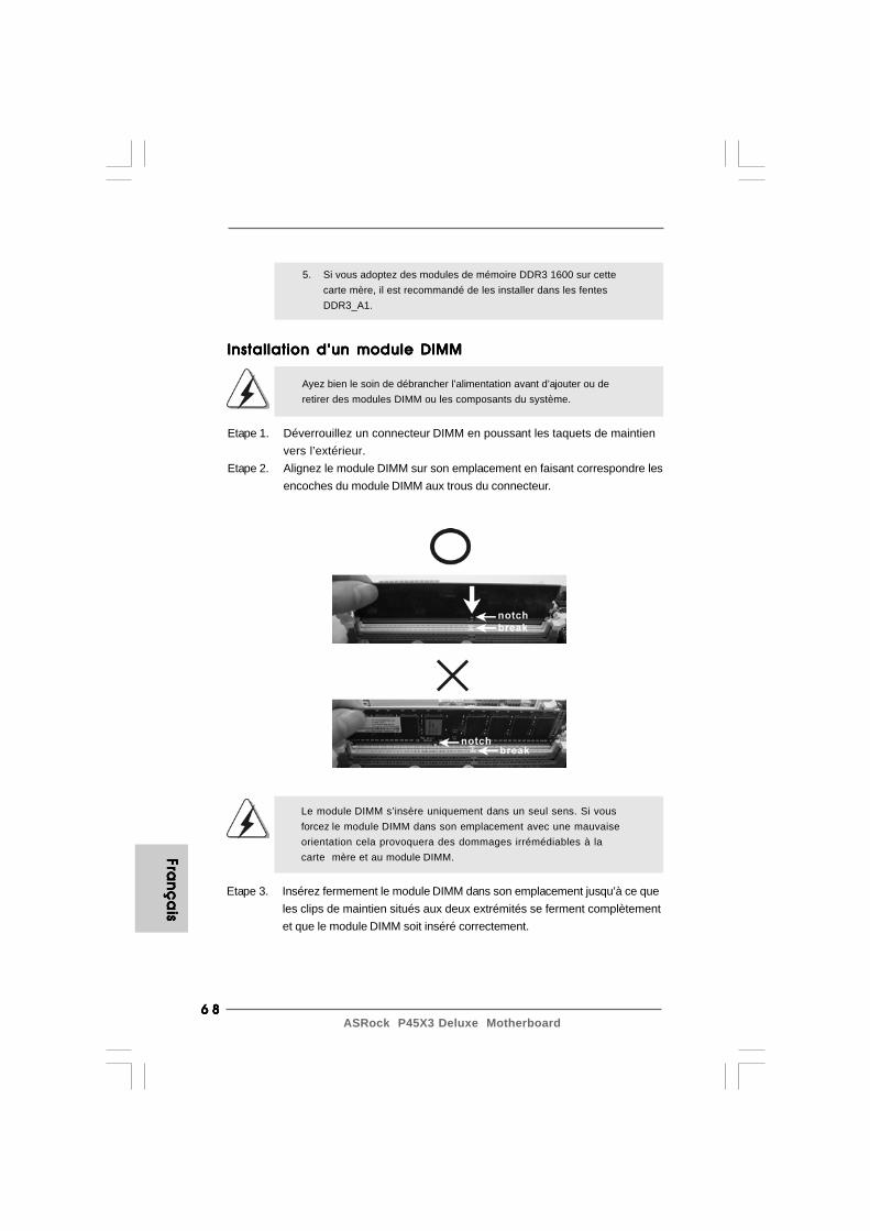
6 86 86 86 86 8ASRock P45X3 Deluxe Motherboard
Fran
ça
isFra
nç
ais
Fran
ça
isFra
nç
ais
Fran
ça
is
Installation d’un module DIMMInstallation d’un module DIMMInstallation d’un module DIMMInstallation d’un module DIMMInstallation d’un module DIMM
Ayez bien le soin de débrancher l’alimentation avant d’ajouter ou deretirer des modules DIMM ou les composants du système.
Etape 1. Déverrouillez un connecteur DIMM en poussant les taquets de maintienvers l’extérieur.
Etape 2. Alignez le module DIMM sur son emplacement en faisant correspondre lesencoches du module DIMM aux trous du connecteur.
Le module DIMM s’insère uniquement dans un seul sens. Si vousforcez le module DIMM dans son emplacement avec une mauvaiseorientation cela provoquera des dommages irrémédiables à lacarte mère et au module DIMM.
Etape 3. Insérez fermement le module DIMM dans son emplacement jusqu’à ce queles clips de maintien situés aux deux extrémités se ferment complètementet que le module DIMM soit inséré correctement.
5. Si vous adoptez des modules de mémoire DDR3 1600 sur cettecarte mère, il est recommandé de les installer dans les fentesDDR3_A1.
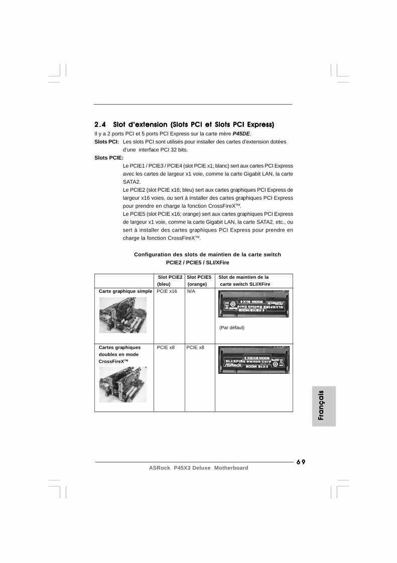
6 96 96 96 96 9ASRock P45X3 Deluxe Motherboard
2.42 .42 .42 .42 .4 Slot d’extension (Slots PCI et Slots PCI Express)Slot d’extension (Slots PCI et Slots PCI Express)Slot d’extension (Slots PCI et Slots PCI Express)Slot d’extension (Slots PCI et Slots PCI Express)Slot d’extension (Slots PCI et Slots PCI Express)Il y a 2 ports PCI et 5 ports PCI Express sur la carte mère P45DE.Slots PCI: Les slots PCI sont utilisés pour installer des cartes d’extension dotées
d’une interface PCI 32 bits.Slots PCIE:
Le PCIE1 / PCIE3 / PCIE4 (slot PCIE x1; blanc) sert aux cartes PCI Expressavec les cartes de largeur x1 voie, comme la carte Gigabit LAN, la carteSATA2.Le PCIE2 (slot PCIE x16; bleu) sert aux cartes graphiques PCI Express delargeur x16 voies, ou sert à installer des cartes graphiques PCI Expresspour prendre en charge la fonction CrossFireXTM.Le PCIE5 (slot PCIE x16; orange) sert aux cartes graphiques PCI Expressde largeur x1 voie, comme la carte Gigabit LAN, la carte SATA2, etc., ousert à installer des cartes graphiques PCI Express pour prendre encharge la fonction CrossFireXTM.
FFFF F ra
nra
nra
nra
nra
nç
ais
ça
isç
ais
ça
isç
ais
Configuration des slots de maintien de la carte switch PCIE2 / PCIE5 / SLI/XFire
Slot PCIE2 Slot PCIE5 Slot de maintien de la (bleu) (orange) carte switch SLI/XFire
Carte graphique simple PCIE x16 N/A
Cartes graphiques PCIE x8 PCIE x8 doubles en mode CrossFireXTM
(Par défaut)
7 07 07 07 07 0ASRock P45X3 Deluxe Motherboard
1. Si vous comptez installer une seule carte VGA PCI Express sur cette carte mère, veuillez l’installer sur le slot PCIE2 (bleu). Dans ce mode, vous n’avez pas besoin d’ajuster le réglage par défaut de la carte switch ASRock SLI/XFire, veuillez ne pas enlever ni desserrer la carte switch ASRock SLI/XFire alors qu’elle est toujours en état de marche.2. Pour l’information du Mode PCI compatible CrossFireXTM Procédures de configuration des cartes Express VGA et CrossFireXTM, référez-vous Au “mode d’emploi CrossFireXTM ” à la page 16.
Installation d’une carte d’extensionInstallation d’une carte d’extensionInstallation d’une carte d’extensionInstallation d’une carte d’extensionInstallation d’une carte d’extensionEtape 1. Avant d’installer les cartes d’extension, veuillez vous assurer de bien
avoir coupé l’alimentation ou d’avoir débranché le cordon d’alimentation.Veuillez lire la documentation des cartes d’extension et effectuer lesréglages matériels nécessaires pour les cartes avant de débuterl’installation.
Etape 2. Retirez l’équerre correspondant au connecteur que vous voulez utiliser.Gardez la vis pour un usage ultérieur.
Etape 3. Alignez la carte sur le connecteur et appuyez fermement jusqu’à l’insertioncomplète de la carte dans son emplacement.
Etape 4. Fixez la carte sur le châssis à l’aide d’une vis.
2.5 Guide d’utilisation de CrossFireX2.5 Guide d’utilisation de CrossFireX2.5 Guide d’utilisation de CrossFireX2.5 Guide d’utilisation de CrossFireX2.5 Guide d’utilisation de CrossFireXTMTMTMTMTM
Cette carte mère prend en charge la fonctionnalité CrossFireXTM. La technologieCrossFireXTM offre le moyen le plus avantageux de combiner plusieursprocesseurs graphiques (GPU) de hautes performances en un PC unique. Encombinant une gamme de modes de fonctionnements différents avec uneconception logicielle intelligente et un mécanisme d’interconnexion innovant,CrossFireXTM permet le plus haut niveau de performances possible et de qualitéd’image dans toute application 3D. Actuellement, la fonctionnalité CrossFireXTM estprise en charge par les OS Windows® XP avec le Service Pack 2 et VistaTM.Veuillez vérifier le site Web d’AMD pour les mises à jour des pilotes ATITM
CrossFireXTM. Pour la procédure de fonctionnement détaillée et la liste des cartesgraphiques PCI Express compatibles, veuillez vous référer à la page 16.
Fran
ça
isFra
nç
ais
Fran
ça
isFra
nç
ais
Fran
ça
is

7 17 17 17 17 1ASRock P45X3 Deluxe Motherboard
2.7 Réglage des cavaliers2.7 Réglage des cavaliers2.7 Réglage des cavaliers2.7 Réglage des cavaliers2.7 Réglage des cavaliersL’illustration explique le réglage des cavaliers.Quand un capuchon est placé sur les broches,le cavalier est « FERME ». Si aucun capuchonne relie les broches,le cavalier est « OUVERT ».L’illustration montre un cavalier à 3 broches dontles broches 1 et 2 sont “FERMEES” quand lecapuchon est placé sur ces 2 broches.
Le cavalier DescriptionPS2_USB_PWR1 Court-circuitez les broches 2(voir p.2 No. 1) et 3 pour choisir +5VSB
(standby) et permettre auxpériphériques PS/2 ou USB deréveiller le système.
Note: Pour sélectionner +5VSB, il faut obligatoirement 2 Amp et un courantstandby supérieur fourni par l’alimentation.
Effacer la CMOS(CLRCMOS1,le cavalier à 3 broches)(voir p.2 No. 40)
Note: CLRCMOS1 vous permet d’effacer les données qui se trouvent dans la CMOS.Les données dans la CMOS comprennent les informations de configuration dusystème telles que le mot de passe système, la date, l’heure et les paramètresde configuration du système. Pour effacer et réinitialiser les paramètres dusystème pour retrouver la configuration par défaut, veuillez mettre l’ordinateurhors tension et débrancher le cordon d’alimentation de l’alimentation électrique.Attendez 15 secondes, puis utilisez un capuchon de cavalier pour court-circuiter la broche 2 et la broche 3 sur CLRCMOS1 pendant 5 secondes. Aprèsavoir court-circuité le cavalier Effacer la CMOS, veuillez enlever le capuchon decavalier. Toutefois, veuillez ne pas effacer la CMOS tout de suite après avoir misle BIOS à jour. Si vous avez besoin d’effacer la CMOS lorsque vous avez fini demettre le BIOS à jour, vous devez d’abord initialiser le système, puis le mettrehors tension avant de procéder à l’opération d’effacement de la CMOS.
Effacer laCMOS
Paramètrespar défaut
Ferme Ouvert
2.6 “Surround Display”2.6 “Surround Display”2.6 “Surround Display”2.6 “Surround Display”2.6 “Surround Display”Cette carte mère supporte la mise à niveau de Surround Display. Avec la carteexterne d’extension VGA PCI Express, vous pouvez facilement jouir desavantages de la caractéristique de l’affichage Surround. Pour les instructionsdétaillées, veuillez vous reporter au document qui se trouve sur le chemin suivantdans le CD d’assistance : ..\ Surround Display Information
FFFF F ra
nra
nra
nra
nra
nç
ais
ça
isç
ais
ça
isç
ais
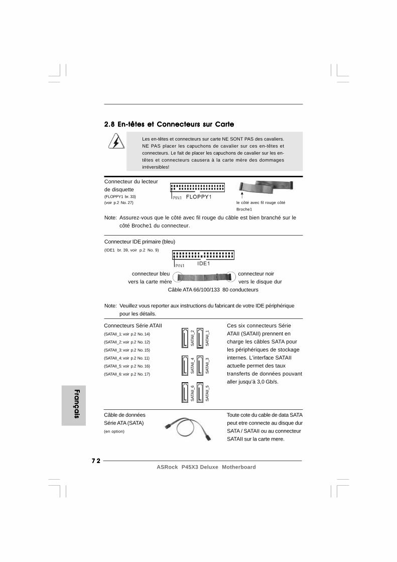
7 27 27 27 27 2ASRock P45X3 Deluxe Motherboard
Fran
ça
isFra
nç
ais
Fran
ça
isFra
nç
ais
Fran
ça
is
le côté avec fil rouge côté
Broche1
2.8 En-têtes et Connecteurs sur Carte2.8 En-têtes et Connecteurs sur Carte2.8 En-têtes et Connecteurs sur Carte2.8 En-têtes et Connecteurs sur Carte2.8 En-têtes et Connecteurs sur Carte
Les en-têtes et connecteurs sur carte NE SONT PAS des cavaliers.NE PAS placer les capuchons de cavalier sur ces en-têtes etconnecteurs. Le fait de placer les capuchons de cavalier sur les en-têtes et connecteurs causera à la carte mère des dommagesirréversibles!
Connecteur du lecteurde disquette(FLOPPY1 br. 33)(voir p.2 No. 27)
Note: Assurez-vous que le côté avec fil rouge du câble est bien branché sur lecôté Broche1 du connecteur.
Connecteur IDE primaire (bleu)(IDE1 br. 39, voir p.2 No. 9)
connecteur bleu connecteur noir vers la carte mère vers le disque dur
Câble ATA 66/100/133 80 conducteurs
Note: Veuillez vous reporter aux instructions du fabricant de votre IDE périphériquepour les détails.
Connecteurs Série ATAII Ces six connecteurs Série(SATAII_1: voir p.2 No. 14) ATAII (SATAII) prennent en(SATAII_2: voir p.2 No. 12) charge les câbles SATA pour(SATAII_3: voir p.2 No. 15) les périphériques de stockage(SATAII_4: voir p.2 No. 11) internes. L’interface SATAII(SATAII_5: voir p.2 No. 16) actuelle permet des taux(SATAII_6: voir p.2 No. 17) transferts de données pouvant
aller jusqu’à 3,0 Gb/s.
Câble de données Toute cote du cable de data SATASérie ATA (SATA) peut etre connecte au disque dur(en option) SATA / SATAII ou au connecteur
SATAII sur la carte mere.
SATA
II_6
SATA
II_4
SATA
II_2
SATA
II_5
SATA
II_3
SATA
II_1

7 37 37 37 37 3ASRock P45X3 Deluxe Motherboard
En-tête du module infrarouge Cet en-tête supporte un module(IR1 br.5) infrarouge optionnel de(voir p.2 No. 34) transfert et de réception sans
fil.
En-tête USB 2.0 A côté des sept ports(US10_11 br.9) USB 2.0 par défaut sur le(voir p.2 No. 20) panneau E/S, il y a deux
embases USB 2.0 sur cettecarte mère. Chaque embaseUSB 2.0 peut prendre en
(US8_9 br.9) charge 2 ports USB 2.0.(voir p.2 No. 22)
Cordon d’alimentation Veuillez connecter l’extrémitéSérie ATA (SATA) noire du cordon d’alimentation(en option) SATA sur le connecteur
d’alimentation sur chaque unité.Connectez ensuite l’extrémitéblanche du cordon d’alimentationSATA sur le connecteurd’alimentation de l’unitéd’alimentation électrique.
c o n n e c t e r àl’unitéd’alimentationélectrique
connecter auconnecteur
d’alimentation dudisque
dur SATA
Fra
nFr
an
Fra
nFr
an
Fra
nç
ais
ça
isç
ais
ça
isç
ais
Connecteurs audio internes Ils vous permettent de gérer des(CD1 br. 4) entrées audio à partir de sources(CD1: voir p.2 No. 34) stéréo comme un CD-ROM,
DVD-ROM, un tuner TV ou unecarte MPEG.
CD1
Ce connecteur prend en chargeun système Trusted PlatformModule (TPM ou module deplateforme de confiance), quipeut stocker des clés desécurité, des certificatsnumériques, des mots de passeet des données. Un systèmeTPM permet également derenforcer la sécurité desréseaux, protège les identitésnumériques, et assure l’intégritéde la plate-forme.
Connecteur TPM(TPM1 br. 19)(voir p.2 No. 26)

7 47 47 47 47 4ASRock P45X3 Deluxe Motherboard
Fran
ça
isFra
nç
ais
Fran
ça
isFra
nç
ais
Fran
ça
is
Connecteur audio panneau C’est une interface pour un câbleavant audio en façade qui permet le(HD_AUDIO1 br. 9) branchement et le contrôle(voir p.2 No. 29) commodes de périphériques
audio.
1. L’audio à haute définition (HDA) prend en charge la détection de fiche, mais le fil de panneau sur le châssis doit prendre en charge le HDA pour fonctionner correctement. Veuillez suivre les instructions dans notre manuel et le manuel de châssis afin installer votre système.2. Si vous utilisez le panneau audio AC’97, installez-le sur l’adaptateur audio du panneau avant conformément à la procédure ci-dessous : A. Connectez Mic_IN (MIC) à MIC2_L. B. Connectez Audio_R (RIN) à OUT2_R et Audio_L (LIN) à OUT2_L. C. Connectez Ground (GND) à Ground (GND). D. MIC_RET et OUT_RET sont réservés au panneau audio HD. Vous n’avez pas besoin de les connecter pour le panneau audio AC’97. E. Entrer dans l’utilitaire de configuration du BIOS. Saisir les Paramètres avancés puis sélectionner Configuration du jeu de puces. Définir l’option panneau de commande de [Auto] à [Activé]. F. Entrer dans le système Windows. Cliquer sur l’icône sur la barre de tâches dans le coin inférieur droite pour entrer dans le Gestionnaire audio Realtek HD. Pour Windows® 2000 / XP / XP 64-bit OS: Cliquer sur « E/S audio», sélectionner « Paramètres du connecteur »
, choisir « Désactiver la détection de la prise du panneau de commande » et sauvegarder les changements en cliquant sur « OK ». Pour Windows® VistaTM / VistaTM 64-bit OS: Cliquer droit “Fichier” icone , selectionner” la detection
incapable de jack de panel d’avant “ et sauvegarder le changement par cliquer”ok”. G. Pour activer le mic.
Pour les SE Windows® 2000 / XP / XP 64 bits : Veuillez sélectionner “Front Mic” ( Mic. Avant) comme le dispositif d’enregistrement par défaut. Si vous voulez entendre votre voix à travers le mic. avant veuillez désactiver l’icône «Silence» dans “Front Mic” ( Mic. Avant) de la portion “Playback” (Lecture). Pour les SE Windows® VistaTM / VistaTM 64 bits : Allez à l’onglet «Front Mic» ( Mic. Avant) dans le panneau de commandes Realtek. Cliquez sur «Configurer le dispositif par défaut» pour faire du Mic Avant le dispositif d’enregistrement par défaut.
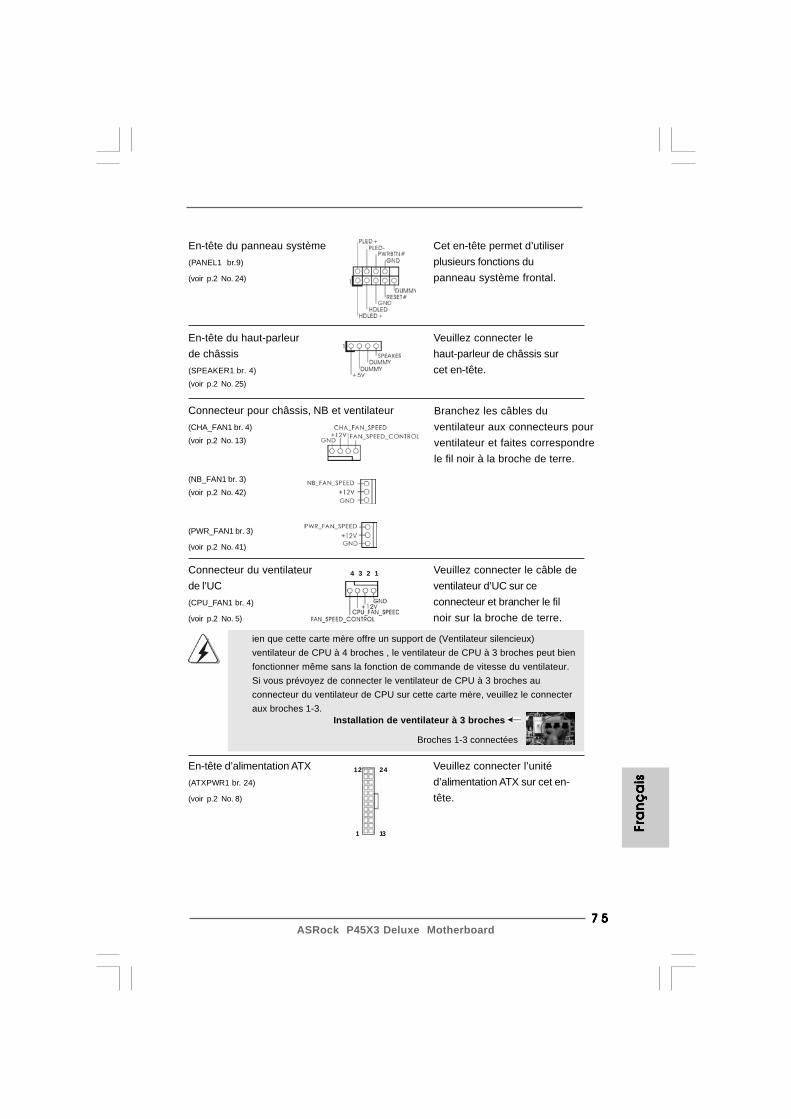
7 57 57 57 57 5ASRock P45X3 Deluxe Motherboard
Fra
nFr
an
Fra
nFr
an
Fra
nç
ais
ça
isç
ais
ça
isç
ais
En-tête du haut-parleur Veuillez connecter lede châssis haut-parleur de châssis sur(SPEAKER1 br. 4) cet en-tête.(voir p.2 No. 25)
En-tête du panneau système Cet en-tête permet d’utiliser(PANEL1 br.9) plusieurs fonctions du(voir p.2 No. 24) panneau système frontal.
Connecteur pour châssis, NB et ventilateur(CHA_FAN1 br. 4)(voir p.2 No. 13)
(NB_FAN1 br. 3)(voir p.2 No. 42)
(PWR_FAN1 br. 3)
(voir p.2 No. 41)
Branchez les câbles duventilateur aux connecteurs pourventilateur et faites correspondrele fil noir à la broche de terre.
4 3 2 1
ien que cette carte mère offre un support de (Ventilateur silencieux)ventilateur de CPU à 4 broches , le ventilateur de CPU à 3 broches peut bienfonctionner même sans la fonction de commande de vitesse du ventilateur.Si vous prévoyez de connecter le ventilateur de CPU à 3 broches auconnecteur du ventilateur de CPU sur cette carte mère, veuillez le connecteraux broches 1-3.
Installation de ventilateur à 3 broches
Broches 1-3 connectées
Connecteur du ventilateur Veuillez connecter le câble dede l’UC ventilateur d’UC sur ce(CPU_FAN1 br. 4) connecteur et brancher le fil(voir p.2 No. 5) noir sur la broche de terre.
En-tête d’alimentation ATX Veuillez connecter l’unité(ATXPWR1 br. 24) d’alimentation ATX sur cet en-(voir p.2 No. 8) tête.
12
1
24
13
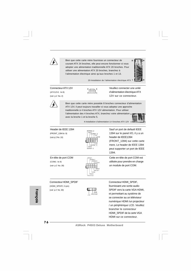
7 67 67 67 67 6ASRock P45X3 Deluxe Motherboard
Fran
ça
isFra
nç
ais
Fran
ça
isFra
nç
ais
Fran
ça
is
Connecteur ATX 12V Veuillez connecter une unité(ATX12V1 br.8) d’alimentation électrique ATX(voir p.2 No. 2) 12V sur ce connecteur.
Bien que cette carte mère possède 8 broches connecteur d’alimentationATX 12V, il peut toujours travailler si vous adoptez une approchetraditionnelle à 4 broches ATX 12V alimentation. Pour utiliserl’alimentation des 4 broches ATX, branchez votre alimentationavec la broche 1 et la broche 5.
4-Installation d’alimentation à 4 broches ATX 12V
En-tête de port COM Cette en-tête de port COM est(COM1 br.9) utilisée pour prendre en charge(voir p.2 No. 28) un module de port COM.
20-Installation de l’alimentation électrique ATX
Bien que cette carte mère fournisse un connecteur decourant ATX 24 broches, elle peut encore fonctionner si vousadopter une alimentation traditionnelle ATX 20 broches. Pourutiliser une alimentation ATX 20 broches, branchez àl’alimentation électrique ainsi qu’aux broches 1 et 13.
12
1
24
13
8 5
4 1
8 5
4 1
Header de IEEE 1394 Sauf un port de default IEEE(FRONT_1394 br. 9) 1394 sur le panel I/O, il y a un(voir p.2 No. 10) header de IEEE1394
(FRONT_1394) sur cette cartemere. Le header de IEEE 1394peut supporter un port de IEEE1394.
Connecteur HDMI_SPDIF Connecteur HDMI_SPDIF,(HDMI_SPDIF1 3-pin) fournissant une sortie audio(voir p.2 No. 30) SPDIF vers la carte VGA HDMI,
et permettant au système dese connecter au un téléviseurnumérique HDMI /un projecteur/ un périphérique LCD. Veuillezbrancher le connecteurHDMI_SPDIF de la carte VGAHDMI sur ce connecteur.

7 77 77 77 77 7ASRock P45X3 Deluxe Motherboard
A. extrémité noire B. extrémité blanche C. extrémité blanche (2 briches) (3 briches)
CB
A
Câble HDMI_SPDIF Veuillez connecter l’extrémité(en option) noire (A) du câble HDMI_SPDIF
au collecteur HDMI_SPDIF de lacarte-mère. Connectez ensuitel’extrémité blanche (B ou C) ducâble HDMI_SPDIF auconnecteur HDMI_SPDIF de lacarte VGA HDMI.
FFFF F ra
nra
nra
nra
nra
nç
ais
ça
isç
ais
ça
isç
ais
V
ATX
12
1
24
13
8 5
4 1
2.9 Interrupteur rapides2.9 Interrupteur rapides2.9 Interrupteur rapides2.9 Interrupteur rapides2.9 Interrupteur rapidesCette carte mère dispose de trois interrupteurs rapides : un interrupteurd’alimentation, un interrupteur de réinitialisation et un interrupteur d’effacement deCMOS, permettant aux utilisateurs de rapidement allumer/éteindre ou réinitialiser lesystème, ainsi que d’effacer les valeurs du CMOS.
Interrupteur d’alimentation(PWRBTN)(voir p.2 No. 19)
RESET
clr
CMOS
L’interrupteur d’effacement deCMOS est un interrupteur rapidequi permet à l’utilisateur d’effacerrapidement les valeurs du CMOS.
Interrupteur de réinitialisation(RSTBTN)(voir p.2 No. 18)
Interrupteur d’effacement de CMOS(CLRCBTN)(voir p.2 No. 17)
L’interrupteur d’alimentation estun interrupteur rapide, qui permetà l’utilisateur d’allumer/éteindrerapidement le système.
L’interrupteur de réinitialisationest un interrupteur rapide, quipermet à l’utilisateur deréinitialiser rapidement lesystème.
Vous n’êtes pas autorisé à utiliser la fonction de l’interrupteur Clear CMOS(Effacement du CMOS) si vous configurez un mot de passe pour lesystème. Si vous voulez effacer les valeurs du CMOS, veuillez d’abordeffacer le mot de passe de votre système ou vous référer plutôt à ladescription “Clear CMOS jumper (Cavalier d’effacement du CMOS)” de lapage 71.
7 87 87 87 87 8ASRock P45X3 Deluxe Motherboard
Fran
ça
isFra
nç
ais
Fran
ça
isFra
nç
ais
Fran
ça
is
ETAPE 1 : Configurez le BIOS.A. Accédez à BIOS SETUP UTILITY (Utilitaire de configuration BIOS) écran Avancé Configuration IDE.B. Réglez «configuration SATAII « sur [Améliorée], et puis dans l’option «Configurer
SATAII comme «, veuillez régler sur [IDE].ETAPE 2 : Installez le système d’exploitation Windows® 2000 / XP / XP 64 bits
sur votre système.
Utilisation des disques durs SATA / SATAII sans NCQ fonctions
2.12.1 Installation de Windows2.12.1 Installation de Windows2.12.1 Installation de Windows2.12.1 Installation de Windows2.12.1 Installation de Windows® 2000 / XP / XP 64-bit 2000 / XP / XP 64-bit 2000 / XP / XP 64-bit 2000 / XP / XP 64-bit 2000 / XP / XP 64-bit
sans fonctions RAID sans fonctions RAID sans fonctions RAID sans fonctions RAID sans fonctions RAIDSi vous voulez installer Windows® 2000 / XP / XP 64-bit sur vos disques dursSATA / SATAII sans les fonctions RAID, veuillez suivre la procédure ci-dessous.
2.12 Installation de Windows2.12 Installation de Windows2.12 Installation de Windows2.12 Installation de Windows2.12 Installation de Windows®®®®® 2000 / XP / XP 64-bit / 2000 / XP / XP 64-bit / 2000 / XP / XP 64-bit / 2000 / XP / XP 64-bit / 2000 / XP / XP 64-bit /
Vista Vista Vista Vista VistaTMTMTMTMTM / Vista / Vista / Vista / Vista / VistaTMTMTMTMTM 64-bit sans fonctions RAID 64-bit sans fonctions RAID 64-bit sans fonctions RAID 64-bit sans fonctions RAID 64-bit sans fonctions RAIDSi vous voulez installer Windows® 2000 / XP / XP 64-bit / VistaTM / VistaTM 64-bits survos disques durs SATA / SATAII sans les fonctions RAID, veuillez suivre lesprocédures ci-dessous, en fonction de l’OS que vous installez.
Depuis Windows® 2000 AHCI pilote n’est pas fourni par le fabricant depuces, les functions AHCI ne sont pas supportées sous Windows® 2000.
2.112.112.112.112.11 Guide d’installation des pilotesGuide d’installation des pilotesGuide d’installation des pilotesGuide d’installation des pilotesGuide d’installation des pilotesPour installer les pilotes sur votre système, veuillez d’abord insérer le CD dans votrelecteur optique. Puis, les pilotes compatibles avec votre système peuvent êtredétectés automatiquement et sont listés sur la page du pilote du CD. Veuillez suivrel’ordre de haut en bas sur le côté pour installer les pilotes requis. En conséquence,les pilotes que vous installez peuvent fonctionner correctement.
2.102.102.102.102.10 LED de débogageLED de débogageLED de débogageLED de débogageLED de débogageLa LED de débogage intégrée sert à fournir des informations de code, ce qui rendle dépannage encore plus facile. Veuillez consulter les diagrammes des pages 28,29 et 30 pour la lecture des codes LED de débogage.
2.12.2 Installation de Windows2.12.2 Installation de Windows2.12.2 Installation de Windows2.12.2 Installation de Windows2.12.2 Installation de Windows® Vista Vista Vista Vista VistaTMTMTMTMTM / Vista / Vista / Vista / Vista / VistaTMTMTMTMTM 64-bit 64-bit 64-bit 64-bit 64-bit
sans fonctions RAID sans fonctions RAID sans fonctions RAID sans fonctions RAID sans fonctions RAIDSi vous voulez installer Windows® Vista
TM / Vista
TM 64-bit sur vos disques durs SATA /
SATAII sans les fonctions RAID, veuillez suivre la procédure ci-dessous.
7 97 97 97 97 9ASRock P45X3 Deluxe Motherboard
FFFF F ra
nra
nra
nra
nra
nç
ais
ça
isç
ais
ça
isç
ais
ETAPE 1 : Configurez le BIOS.A. Accédez à BIOS SETUP UTILITY (Utilitaire de configuration BIOS) écran Avancé Configuration IDE.B. Réglez «configuration SATAII « sur [Améliorée], et puis dans l’option «Configurer
SATAII comme «, veuillez régler sur [IDE].ETAPE 2: Installer le système d’exploitation Windows® VistaTM / VistaTM 64-bit
sur votre système.
ETAPE 1 : Configurez le BIOS.A. Accédez à BIOS SETUP UTILITY (Utilitaire de configuration BIOS) écran Avancé Configuration IDE.B. Réglez «configuration SATAII « sur [Améliorée], et puis dans l’option «Configurer
SATAII comme «, veuillez régler sur [AHCI].ETAPE 2: Installer le système d’exploitation Windows® VistaTM / VistaTM 64-bit
sur votre système.Insérez le disque optique de Windows® VistaTM / VistaTM 64-bits dans le lecteuroptique pour démarrer votre système, et suivez les instructions pour installer l’OSWindows® VistaTM / VistaTM 64-bits sur votre système. Lorsque vous voyez la page“Où souhaitez-vous installer Windows ?”, veuillez insérer le CD Support d’ ASRockdans votre lecteur optique, et cliquer sur le bouton “Charger le pilote” en bas à gauchepour charger les pilotes AHCI Intel®. Les pilotes AHCI Intel® sont sous le cheminsuivant du CD Support:.. \ I386 (Pour les utilisateurs de Windows® VistaTM).. \ AMD64 (Pour les utilisateurs de Windows® VistaTM 64-bits)Ensuite, veuillez insérer le disque optique de Windows® VistaTM / VistaTM 64-bits dansle lecteur optique de nouveau pour continuer l’installation.
Utilisation des disques durs SATA / SATAII avec NCQ fonctions
2.132.132.132.132.13 La technologie de surcadençage à la voléeLa technologie de surcadençage à la voléeLa technologie de surcadençage à la voléeLa technologie de surcadençage à la voléeLa technologie de surcadençage à la voléeCette carte mère prend en charge la technologie de surcadençage à la volée,durant le surcadençage, FSB jouit d’une marge meilleure résultant des bus PCI /PCIE fixés. Avant d’activer la technologie de surcadençage à la volée, veuillezentrer l’option “Mode de surcadençage” de la configuration du BIOS pour établir lasélection de [Auto] à [Manual]. Par conséquent, le CPU FSB n’est pas lié durant lesurcadençage, mais les bus PCI / PCIE sont en mode fixé de sorte que FSB peutopérer sous un environnement de surcadençage plus stable.
Veuillez vous reporter à l’avertissement en page 61 pour connaître les risquesliés à l’overclocking avant d’appliquer la technologie Untied Overclocking.
Utilisation des disques durs SATA / SATAII sans NCQ fonctions

8 08 08 08 08 0ASRock P45X3 Deluxe Motherboard
3. Informations sur le BIOSLa puce Flash Memory sur la carte mère stocke le Setup du BIOS. Lorsque vousdémarrez l’ordinateur, veuillez presser <F2> pendant le POST (Power-On-Self-Test) pour entrer dans le BIOS; sinon, le POST continue ses tests de routine. Sivous désirez entrer dans le BIOS après le POST, veuillez redémarrer le systèmeen pressant <Ctl> + <Alt> + <Suppr>, ou en pressant le bouton de reset sur leboîtier du système. Vous pouvez également redémarrer en éteignant le système eten le rallumant. L’utilitaire d’installation du BIOS est conçu pour être convivial. C’estun programme piloté par menu, qui vous permet de faire défiler par ses diverssous-menus et de choisir parmi les choix prédéterminés. Pour des informationsdétaillées sur le BIOS, veuillez consulter le Guide de l’utilisateur (fichier PDF) dansle CD technique.
4. Informations sur le CD de support4. Informations sur le CD de support4. Informations sur le CD de support4. Informations sur le CD de support4. Informations sur le CD de supportCette carte mère supporte divers systèmes d’exploitation Microsoft® Windows®:2000 / XP / XP 64 bits / VistaTM / VistaTM 64 bits. Le CD technique livré avec cettecarte mère contient les pilotes et les utilitaires nécessaires pour améliorer lesfonctions de la carte mère. Pour utiliser le CD technique, insérez-le dans le lecteurde CD-ROM. Le Menu principal s’affiche automatiquement si “AUTORUN” est activédans votre ordinateur. Si le Menu principal n’apparaît pas automatiquement,localisez dans le CD technique le fichier “ASSETUP.EXE” dans le dossier BIN etdouble-cliquez dessus pour afficher les menus.
Fran
ça
isFra
nç
ais
Fran
ça
isFra
nç
ais
Fran
ça
is
8 18 18 18 18 1ASRock P45X3 Deluxe Motherboard
1. IntroduzioneGrazie per aver scelto una scheda madre ASRock P45X3 Deluxe, una schedamadre affidabile prodotta secondo i severi criteri di qualità ASRock. Le prestazionieccellenti e il design robusto si conformano all’impegno di ASRock nella ricerca dellaqualità e della resistenza.Questa Guida Rapida all’Installazione contiene l’introduzione alla motherboard e la guidapasso-passo all’installazione. Informazioni più dettagliate sulla motherboard si possonotrovare nel manuale per l’utente presente nel CD di supporto.
Le specifiche della scheda madre e il software del BIOS possonoessere aggiornati, pertanto il contenuto di questo manuale può subirevariazioni senza preavviso. Nel caso in cui questo manuale siamodificato, la versione aggiornata sarà disponibile sul sito di ASRocksenza altro avviso. Sul sito ASRock si possono anche trovare le piùrecenti schede VGA e gli elenchi di CPU supportate.ASRock website http://www.asrock.comSe si necessita dell’assistenza tecnica per questa scheda madre,visitare il nostro sito per informazioni specifiche sul modello che sista usando.www.asrock.com/support/index.asp
1.1 Contenuto della confezione1.1 Contenuto della confezione1.1 Contenuto della confezione1.1 Contenuto della confezione1.1 Contenuto della confezioneScheda madre ASRock P45X3 Deluxe
(ATX Form Factor: 12.0-in x 9.6-in, 30.5 cm x 24.4 cm)Guida di installazione rapida ASRock P45X3 DeluxeCD di supporto ASRock P45X3 DeluxeUna scheda Switch ASRock SLI/XFireUn cavo IDE 80-pin Ultra ATA 66/100/133Un cavo per floppy drive a 1,44 MbQuattro cavi dati Serial ATA (SATA) (opzionali)Un cavi di alimentazione HDD Serial ATA (SATA) (opzionali)Un I/O Shield
Ita
lia
no
Ita
lia
no
Ita
lia
no
Ita
lia
no
Ita
lia
no

8 28 28 28 28 2ASRock P45X3 Deluxe Motherboard
Italia
no
Italia
no
Italia
no
Italia
no
Italia
no
1.21.21.21.21.2 SpecificheSpecificheSpecificheSpecificheSpecifiche
Piattaforma - ATX Form Factor: 12.0-in x 9.6-in, 30.5 cm x 24.4 cm- Design condensatore compatto (condensatori a conduttore in polimero di alta qualità realizzati al 100% in Giappone)
Processore - LGA 775 per Intel® CoreTM 2 Extreme / CoreTM 2 Quad / CoreTM 2 Duo / Pentium® Dual Core / Celeron® Dual Core / Celeron® in grado di supportare processori Penryn Quad Core Yorkfield e Dual Core Wolfdale- Compatibile con FSB2000/1600/1333/1066/800 MHz (vedi ATTENZIONE 1)- Struttura di fase con alimentazione V8 avanzata- Supporto tecnologia Hyper Threading (vedi ATTENZIONE 2)- Supporta la tecnologia overclocking “slegata” (vedi ATTENZIONE 3)- Supporto CPU EM64T
Chipset - Northbridge: Intel® P45- Southbridge: Intel® ICH10
Memoria - Supporto tecnologia Dual Channel DDR3 Memory (vedi ATTENZIONE 4)
- 4 x slot DDR3 DIMM- Supporto DDR3 1600/1333/1066/800 non-ECC, momoria senza buffer (vedi ATTENZIONE 5)- Capacità massima della memoria di sistema: 16GB (vedi ATTENZIONE 6)
Slot di - 2 x slot PCI Express 2.0 x16 espansione (blu a modalità x16, arancione a modalità x8)
- 3 x slot PCI Express x1- 2 x slot PCI- Supporto di ATITM CrossFireXTM (vedi ATTENZIONE 7)
Audio - 7.1 Audio HD CH Windows® VistaTM Premium Level (ALC888 Audio Codec)
LAN - PCIE x1 Gigabit LAN 10/100/1000 Mb/s- Realtek RTL8111DL- Supporta Wake-On-LAN
Pannello I/O Panel posteriore I/O - 1 x porta PS/2 per mouse
- 1 x porta PS/2 per tastiera- 1 x Porta coassiale SPDIF Out- 1 x Porta ottica SPDIF Out- 1 x porte IEEE 1394- 7 x porte USB 2.0 già integrate
8 38 38 38 38 3ASRock P45X3 Deluxe Motherboard
- 1 x Connettore alimentato eSATAII/USB- 1 x porte LAN RJ-45 con LED (LED azione/collegamento e LED velocità)- 1 x interruttore di pulizia CMOS con LED- Connettore HD Audio: cassa laterale / cassa posteriore / cassa centrale / bassi / ingresso linea / cassa frontale / microfono (vedi ATTENZIONE 8)
Connettori - 6 x connettori SATAII 3.0Go/s, sopporta NCQ, AHCI e “Collegamento a caldo” (vedi ATTENZIONE 9)- 1 x connettori ATA133 IDE (supporta fino a 2 dispositivi IDE)- 1 x porta Floppy- 1 x Collettore modulo infrarossi- 1 x collettore porta COM- 1 x connettore HDMI_SPDIF- 1 x collettore IEEE 1394- 1 x collettore TPM- Connettore CPU/Chassis/NB/Alimentazione ventola- 24-pin collettore alimentazione ATX- 8-pin connettore ATX 12V- Connettori audio interni- Connettore audio sul pannello frontale- 2 x Collettore USB 2.0 (supporta 4 porte USB 2.0)
(vedi ATTENZIONE 10) Interruttore - 1 x interruttore pulizia CMOS con LED rapido - 1 x interruttore di alimentazione con LED
- 1 x interruttore di reset con LED BIOS - 8Mb AMI BIOS
- Suppor AMI legal BIOS- Supporta “Plug and Play”- Compatibile con ACPI 1.1 wake up events- Supporta jumperfree- Supporta SMBIOS 2.3.1- Regolazione multi-voltaggio CPU, VCCM, VTT- Supporto I. O. T. (Intelligent Overclocking Technology)- Smart BIOS supportato
CD di - Driver, utilità, software antivirus (Versione dimostrativa) supporto Caratteristica - Sintonizzatore ASRock OC (vedi ATTENZIONE 11) speciale - Intelligent Energy Saver (Risparmio intelligente dell’energia)
(vedi ATTENZIONE 12)- Instant Boot- ASRock Instant Flash (vedi ATTENZIONE 13)
Ita
lia
no
Ita
lia
no
Ita
lia
no
Ita
lia
no
Ita
lia
no
8 48 48 48 48 4ASRock P45X3 Deluxe Motherboard
Italia
no
Italia
no
Italia
no
Italia
no
Italia
no
AVVISOSi prega di prendere atto che la procedura di overclocking implica dei rischi, come anchela regolazione delle impostazioni del BIOS, l’applicazione della tecnologia Untied OverclockingTechnology, oppure l’uso di strumenti di overclocking forniti da terzi. L’overclocking puòinfluenzare la stabilità del sistema, ed anche provocare danni ai componenti ed alleperiferiche del sistema. La procedura è eseguita a proprio rischio ed a proprie spese. Noinon possiamo essere ritenuti responsabili per possibili danni provocati dall’overclocking.
ATTENZIONE!1. Alcune delle CPU utilizzare potrebbero avere un overclock a FSB2000
MHz, questi casi, si raccomanda di utilizzare moduli di memoria DDR31333 o DDR3 1600 su questa scheda madre.
2. Per il settaggio della “Tecnologia Hyper-Threading”, per favorecontrollare pagina 49 del Manuale dell’utente all’interno del CD disupporto.
3. Questa scheda madre supporta la tecnologia overclocking “slegata”.Per i dettagli leggere “Tecnologia di Untied Overclocking” a pagina 102.
4. Questa scheda madre supporta la tecnologia Dual Channel Memory.Prima di implementare la tecnologia Dual Channel Memory, assicurarsidi leggere la guida all’installazione dei moduli di memoria, a pagina 90, perseguire un’installazione appropriata.
5. Controllare la tavola che segue per le frequenze di supporto dimemoria e le loro corrispondenti frequenze CPU FSB.
Fréquence FSB UC Fréquence de prise en charge mémoire1600 DDR3 800, DDR3 1066, DDR3 1333,
DDR3 16001333 DDR3 800, DDR3 1066, DDR3 13331066 DDR3 800, DDR3 1066800 DDR3 800
- Booster ibrido:- Stepless control per frequenza del processore (vedi ATTENZIONE 14)- ASRock U-COP (vedi ATTENZIONE 15)- Boot Failure Guard (B.F.G.)
Monitoraggio - Sensore per la temperatura del processore Hardware - Sensore temperatura scheda madre
- Indicatore di velocità per la ventola del CPU/Chassis/NB/ Alimentazione- Ventola CPU silenziosa- Voltaggio: +12V, +5V, +3.3V, Vcore
Compatibi- - Microsoft® Windows® 2000 / XP / XP 64 bit / VistaTM / lità SO VistaTM 64 bit (vedi ATTENZIONE 16) Certificazioni - FCC, CE, WHQL * Per ulteriori informazioni, prego visitare il nostro sito internet: http://www.asrock.com
8 58 58 58 58 5ASRock P45X3 Deluxe Motherboard
* I moduli di memoria DDR3 1600 funzioneranno in modalita‘ di sincronizzazione.6. A causa delle limitazioni del sistema operativo, le dimensioni effettive
della memoria possono essere inferiori a 4GB per l’accantonamentoriservato all’uso del sistema sotto Windows® XP e Windows® VistaTM. PerWindows® XP 64-bit e Windows® VistaTM 64-bit con CPU 64-bit, non c’ètale limitazione.
7. Questa scheda madre supporta la tecnologia ATITM CrossFireXTM. Perutilizzare la funzione CrossFireXTM, seguire le istruzioni a pagina 17 perinvertire la direzione della ASRock SLI/XFire Switch Card.
8. Questa scheda madre supporta l’ingresso stereo e mono per ilmicrofono. Questa scheda madre supporta le modalità 2 canali, 4canali, 6 canali e 8 canali per l’uscita audio. Controllare la tavola apagina 3 per eseguire il collegamento appropriato.
9. Prima di installare il disco rigido SATAII con il connettore SATAII, leggere la“Guida per la configurazione del disco rigido SATAII” a pagina 37 del“Manuale utente” nel CD in dotazione in modo da poter predisporre il discorigido SATAII per la modalità SATAII. È anche possibile connettere il discorigido SATA direttamente al connettore SATAII.
10. La Gestione Risorse per USB 2.0 funziona perfettamente con Microsoft®
Windows® VistaTM 64-bit / VistaTM / XP 64 bit / XP SP1; SP2/2000 SP4.11. Si tratta di uno strumento di sicronizzazione ASRock di face uso in grado
di implementare il controllo del sistema tramite la funzione di hardwaremonitor e sincronizzare le Vostre unita‘ hardware per ottenere la miglioreprestazione in Windows?. Prego visitare il nostro sito Internet per ulterioridettagli circa l‘uso del Sintonizzatore ASRock OC.ASRock website: http://www.asrock.com
12. Dotato di un design avanzato e brevettato dell’hardware e del software,Intelligent Energy Saver è una tecnologia rivoluzionaria che offre unrisparmio energetico senza pari. In altre parole: è capace di fornire unrisparmio energetico eccezionale e di migliorare l’efficienza senzasacrificare le prestazioni di computazione. Visitare il nostro sito perinformazioni sulle procedure operative di Intelligent Energy Saver.Sito ASRock: http://www.asrock.com
13. ASRock Instant Flash è una utilità Flash BIOS integrata nella Flash ROM.Questo comodo strumento d’aggiornamento del BIOS permette diaggiornare il sistema BIOS senza accedere a sistemi operativi come MS-DOS or Windows®. Con questa utilità, si può premere il tasto <F6>durante il POST, oppure il tasto <F2> nel menu BIOS per accedere adASRock Instant Flash. Avviare questo strumento e salvare il nuovo fileBIOS nell’unità Flash USB, dischetto (disco floppy) o disco rigido; poi sipuò aggiornare il BIOS con pochi clic, senza preparare altri dischetti(dischi floppy) o altre complicate utilità Flash. Si prega di notare chel’unità Flash USB o il disco rigido devono usare il File System FAT32/16/12.
Ita
lia
no
Ita
lia
no
Ita
lia
no
Ita
lia
no
Ita
lia
no
8 68 68 68 68 6ASRock P45X3 Deluxe Motherboard
Italia
no
Italia
no
Italia
no
Italia
no
Italia
no
2. Installazione2. Installazione2. Installazione2. Installazione2. Installazione
Precauzioni preinstallazionePrecauzioni preinstallazionePrecauzioni preinstallazionePrecauzioni preinstallazionePrecauzioni preinstallazioneLeggere le seguenti precauzioni prima di installare componenti delleschede madri o di cambiare le impostazioni delle schede madri.
1. Togliere il cavo dalla presa elettrica prima di toccare lecomponenti. In caso contrario la schedamadre, le periferiche,e/o i componenti possono subire gravi danni.
2. Per evitare che l’elettricità statica danneggi la scheda madre,NON appoggiare la scheda madre su moquette, tappeti o tessutisimili. Ricordarsi di indossare un braccialetto antistaticocollegato a terra o di toccare un oggetto posizionato a terraprima di maneggiare le componenti.
3. Tenere i componenti per i bordi e non toccare i ICs.4. Ogni volta che si disinstalla un componente, appoggiarlo su un
tappetino antistatico messo a terra o depositarlo nella borsadata in dotazione con il componente.
5. Nell’usare i giraviti per fissare la scheda madre al telaio nonserrare eccessivamente le viti! Altrimenti si rischia didanneggiare la scheda madre.
14. Anche se questa motherboard offre il controllo stepless, non si consigliadi effettuare l’overclocking. Frequenze del bus del processore diverseda quelle raccomandate possono causare instabilità al sistema o dannial processore e alla scheda madre.
15. Se il processore si surriscalda, il sistema si chiude automaticamente.Prima di riavviare il sistema, assicurarsi che la ventolina CPU dellascheda madre funzioni correttamente; scollegaree ricollegare il cavo d’alimentazione. Per migliorare la dissipazione delcalore, ricordare di applicare l’apposita pasta siliconica tra il processore eil dissipatore quando si installa il sistema.
16. Funzioni AHCI non sono supportate da Windows® 2000 OS. InWindows® 2000 si consiglia l’uso della modalità IDE. Consultare pagina59 del “Manuale utente” nel CD in dotazione per avere informazionidettagliate sulla configurazione.
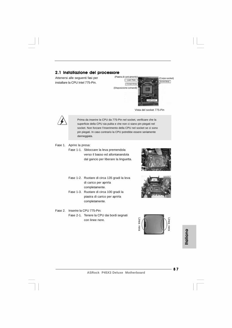
8 78 78 78 78 7ASRock P45X3 Deluxe Motherboard
2.1 Installazione del processore2.1 Installazione del processore2.1 Installazione del processore2.1 Installazione del processore2.1 Installazione del processoreAttenersi alle seguenti fasi perinstallare la CPU Intel 775-Pin.
Prima da inserire la CPU da 775-Pin nel socket, verificare che lasuperficie della CPU sia pulita e che non ci siano pin piegati nelsocket. Non forzare l’inserimento della CPU nel socket se ci sonopin piegati. In caso contrario la CPU potrebbe essere seriamentedanneggiata.
Fase 1. Aprire la presa:Fase 1-1. Sbloccare la leva premendola
verso il basso ed allontanandoladal gancio per liberare la linguetta.
Fase 1-2. Ruotare di circa 135 gradi la levadi carico per aprirlacompletamente.
Fase 1-3. Ruotare di circa 100 gradi lapiastra di carico per aprirlacompletamente.
Fase 2. Inserire la CPU 775-Pin:Fase 2-1. Tenere la CPU dai bordi segnati
con linee nere.
Vista del socket 775-Pin
Linea nera
Linea nera
(Piastra di caricamento)
(Disposizione comandi)
(Corpo socket)
Ita
lia
no
Ita
lia
no
Ita
lia
no
Ita
lia
no
Ita
lia
no
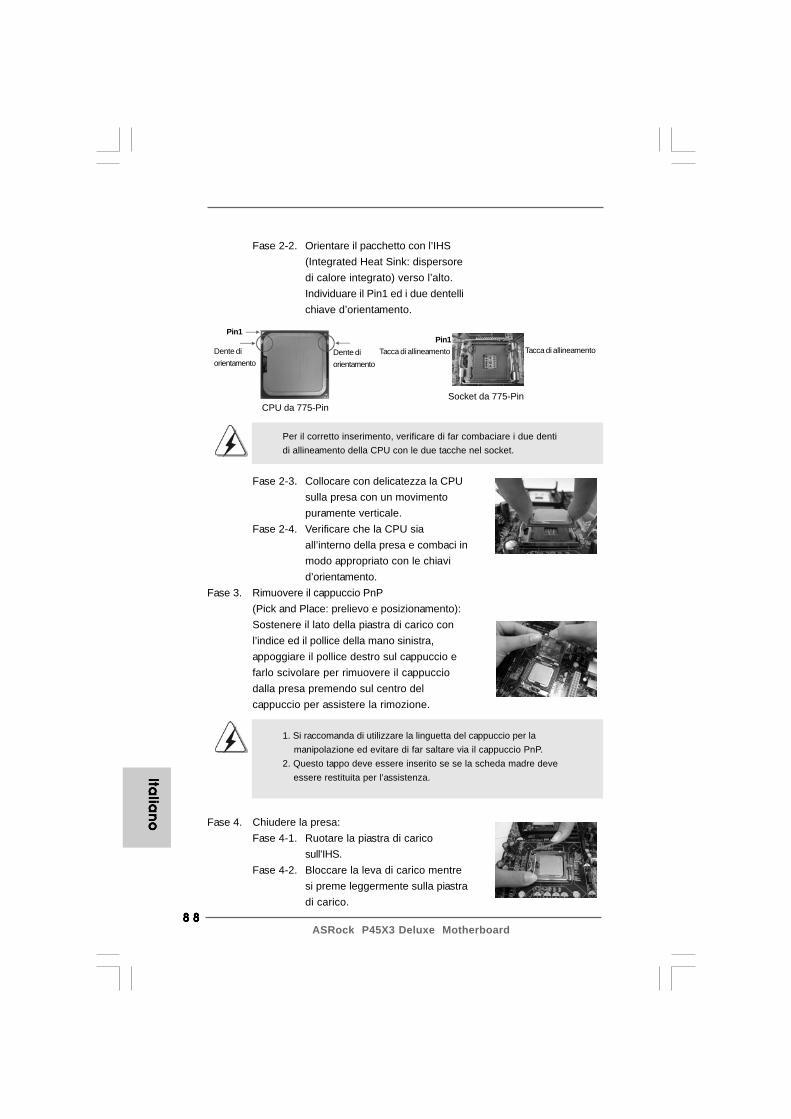
8 88 88 88 88 8ASRock P45X3 Deluxe Motherboard
Italia
no
Italia
no
Italia
no
Italia
no
Italia
no
Fase 2-2. Orientare il pacchetto con l’IHS(Integrated Heat Sink: dispersoredi calore integrato) verso l’alto.Individuare il Pin1 ed i due dentellichiave d’orientamento.
Per il corretto inserimento, verificare di far combaciare i due dentidi allineamento della CPU con le due tacche nel socket.
Fase 2-3. Collocare con delicatezza la CPUsulla presa con un movimentopuramente verticale.
Fase 2-4. Verificare che la CPU siaall’interno della presa e combaci inmodo appropriato con le chiavid’orientamento.
Fase 3. Rimuovere il cappuccio PnP(Pick and Place: prelievo e posizionamento):Sostenere il lato della piastra di carico conl’indice ed il pollice della mano sinistra,appoggiare il pollice destro sul cappuccio efarlo scivolare per rimuovere il cappucciodalla presa premendo sul centro delcappuccio per assistere la rimozione.
1. Si raccomanda di utilizzare la linguetta del cappuccio per la manipolazione ed evitare di far saltare via il cappuccio PnP.2. Questo tappo deve essere inserito se se la scheda madre deve essere restituita per l’assistenza.
Fase 4. Chiudere la presa:Fase 4-1. Ruotare la piastra di carico
sull’IHS.Fase 4-2. Bloccare la leva di carico mentre
si preme leggermente sulla piastradi carico.
Socket da 775-Pin
Pin1Tacca di allineamento
Pin1
Dente diorientamento
Dente diorientamento
CPU da 775-Pin
Tacca di allineamento
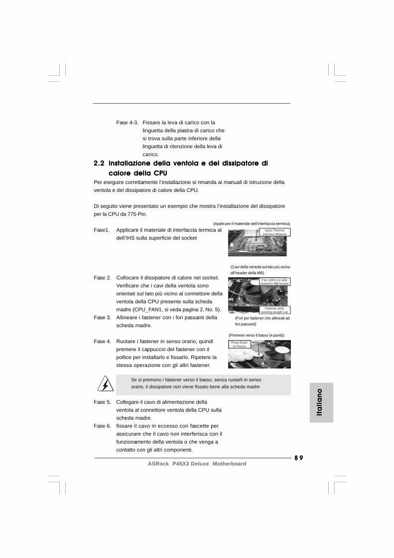
8 98 98 98 98 9ASRock P45X3 Deluxe Motherboard
Fase 4-3. Fissare la leva di carico con lalinguetta della piastra di carico chesi trova sulla parte inferiore dellalinguetta di ritenzione della leva dicarico.
2.22.22.22.22.2 Installazione della ventola e del dissipatore diInstallazione della ventola e del dissipatore diInstallazione della ventola e del dissipatore diInstallazione della ventola e del dissipatore diInstallazione della ventola e del dissipatore di
calore della CPUcalore della CPUcalore della CPUcalore della CPUcalore della CPUPer eseguire correttamente l’installazione si rimanda ai manuali di istruzione dellaventola e del dissipatore di calore della CPU.
Di seguito viene presentato un esempio che mostra l’installazione del dissipatoreper la CPU da 775-Pin.
Fase1. Applicare il materiale di interfaccia termica aldell’IHS sulla superficie del socket
Fase 2. Collocare il dissipatore di calore nel socket.Verificare che i cavi della ventola sonoorientati sul lato più vicino al connettore dellaventola della CPU presente sulla schedamadre (CPU_FAN1, si veda pagina 2, No. 5).
Fase 3. Allineare i fastener con i fori passanti dellascheda madre.
Fase 4. Ruotare i fastener in senso orario, quindipremere il cappuccio del fastener con ilpollice per installarlo e fissarlo. Ripetere lastessa operazione con gli altri fastener.
Se si premono i fastener verso il basso, senza ruotarli in sensoorario, il dissipatore non viene fissato bene alla scheda madre
Fase 5. Collegare il cavo di alimentazione dellaventola al connettore ventola della CPU sullascheda madre.
Fase 6. fissare il cavo in eccesso con fascette perassicurare che il cavo non interferisca con ilfunzionamento della ventola o che venga acontatto con gli altri componenti.
(Applicare il materiale dell’interfaccia termica)
(Cavi della ventola sul lato più vicinoall’header della MB)
(Fori per fastener che allineati adfori passanti)
(Premere verso il basso (4 punti))
Ita
lia
no
Ita
lia
no
Ita
lia
no
Ita
lia
no
Ita
lia
no
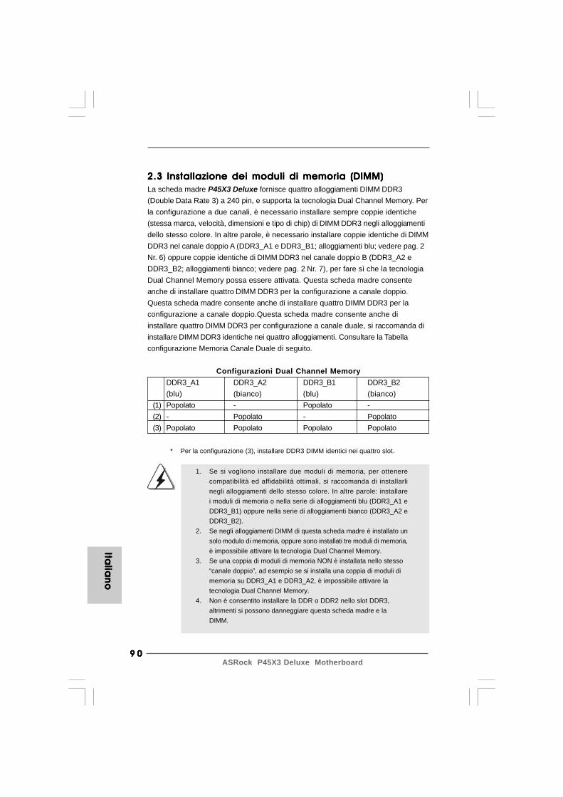
9 09 09 09 09 0ASRock P45X3 Deluxe Motherboard
Italia
no
Italia
no
Italia
no
Italia
no
Italia
no
2.3 Installazione dei moduli di memoria (DIMM)2.3 Installazione dei moduli di memoria (DIMM)2.3 Installazione dei moduli di memoria (DIMM)2.3 Installazione dei moduli di memoria (DIMM)2.3 Installazione dei moduli di memoria (DIMM)La scheda madre P45X3 Deluxe fornisce quattro alloggiamenti DIMM DDR3(Double Data Rate 3) a 240 pin, e supporta la tecnologia Dual Channel Memory. Perla configurazione a due canali, è necessario installare sempre coppie identiche(stessa marca, velocità, dimensioni e tipo di chip) di DIMM DDR3 negli alloggiamentidello stesso colore. In altre parole, è necessario installare coppie identiche di DIMMDDR3 nel canale doppio A (DDR3_A1 e DDR3_B1; alloggiamenti blu; vedere pag. 2Nr. 6) oppure coppie identiche di DIMM DDR3 nel canale doppio B (DDR3_A2 eDDR3_B2; alloggiamenti bianco; vedere pag. 2 Nr. 7), per fare sì che la tecnologiaDual Channel Memory possa essere attivata. Questa scheda madre consenteanche di installare quattro DIMM DDR3 per la configurazione a canale doppio.Questa scheda madre consente anche di installare quattro DIMM DDR3 per laconfigurazione a canale doppio.Questa scheda madre consente anche diinstallare quattro DIMM DDR3 per configurazione a canale duale, si raccomanda diinstallare DIMM DDR3 identiche nei quattro alloggiamenti. Consultare la Tabellaconfigurazione Memoria Canale Duale di seguito.
Configurazioni Dual Channel MemoryDDR3_A1 DDR3_A2 DDR3_B1 DDR3_B2(blu) (bianco) (blu) (bianco)
(1) Popolato - Popolato -(2) - Popolato - Popolato(3) Popolato Popolato Popolato Popolato
* Per la configurazione (3), installare DDR3 DIMM identici nei quattro slot.
1. Se si vogliono installare due moduli di memoria, per ottenerecompatibilità ed affidabilità ottimali, si raccomanda di installarlinegli alloggiamenti dello stesso colore. In altre parole: installarei moduli di memoria o nella serie di alloggiamenti blu (DDR3_A1 eDDR3_B1) oppure nella serie di alloggiamenti bianco (DDR3_A2 eDDR3_B2).
2. Se negli alloggiamenti DIMM di questa scheda madre è installato unsolo modulo di memoria, oppure sono installati tre moduli di memoria,è impossibile attivare la tecnologia Dual Channel Memory.
3. Se una coppia di moduli di memoria NON è installata nello stesso“canale doppio”, ad esempio se si installa una coppia di moduli dimemoria su DDR3_A1 e DDR3_A2, è impossibile attivare latecnologia Dual Channel Memory.
4. Non è consentito installare la DDR o DDR2 nello slot DDR3,altrimenti si possono danneggiare questa scheda madre e laDIMM.
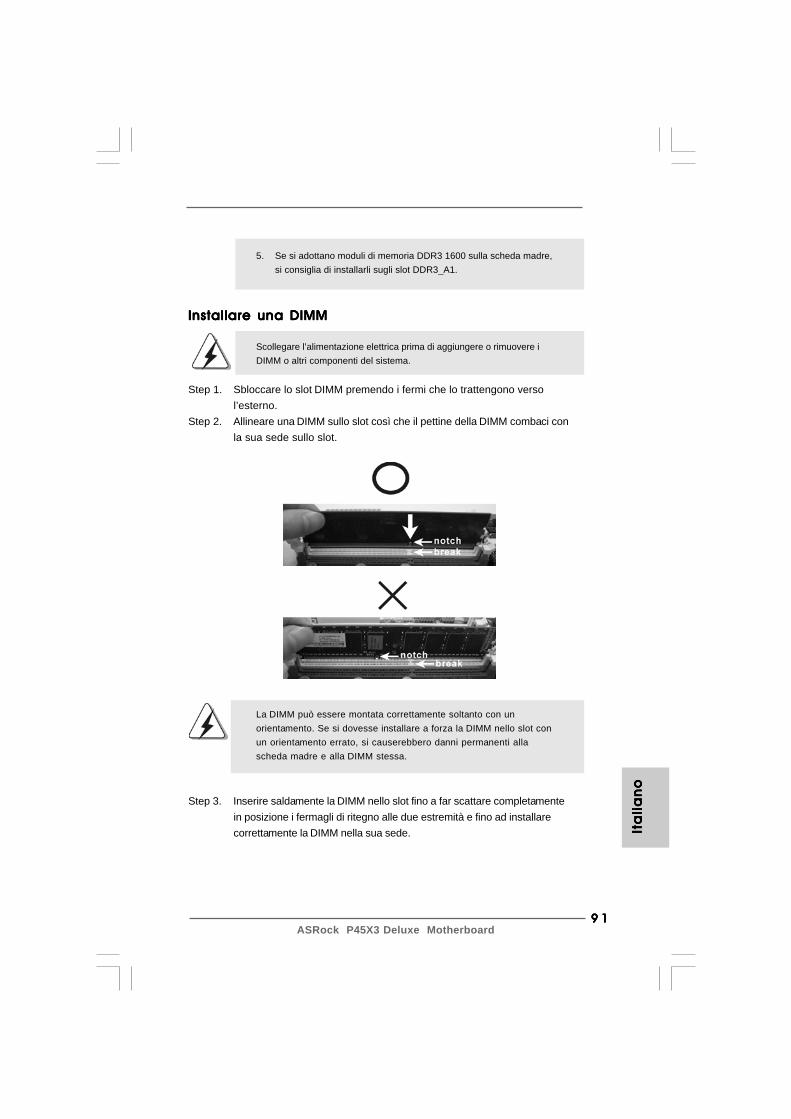
9 19 19 19 19 1ASRock P45X3 Deluxe Motherboard
Installare una DIMMInstallare una DIMMInstallare una DIMMInstallare una DIMMInstallare una DIMM
Scollegare l’alimentazione elettrica prima di aggiungere o rimuovere iDIMM o altri componenti del sistema.
Step 1. Sbloccare lo slot DIMM premendo i fermi che lo trattengono versol’esterno.
Step 2. Allineare una DIMM sullo slot così che il pettine della DIMM combaci conla sua sede sullo slot.
La DIMM può essere montata correttamente soltanto con unorientamento. Se si dovesse installare a forza la DIMM nello slot conun orientamento errato, si causerebbero danni permanenti allascheda madre e alla DIMM stessa.
Step 3. Inserire saldamente la DIMM nello slot fino a far scattare completamentein posizione i fermagli di ritegno alle due estremità e fino ad installarecorrettamente la DIMM nella sua sede. It
ali
an
oIt
ali
an
oIt
ali
an
oIt
ali
an
oIt
ali
an
o
5. Se si adottano moduli di memoria DDR3 1600 sulla scheda madre,si consiglia di installarli sugli slot DDR3_A1.
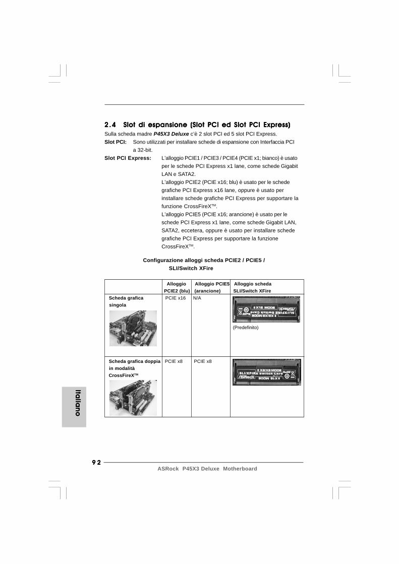
9 29 29 29 29 2ASRock P45X3 Deluxe Motherboard
2.42 .42 .42 .42 .4 Slot di espansione (Slot PCI ed Slot PCI Express)Slot di espansione (Slot PCI ed Slot PCI Express)Slot di espansione (Slot PCI ed Slot PCI Express)Slot di espansione (Slot PCI ed Slot PCI Express)Slot di espansione (Slot PCI ed Slot PCI Express)Sulla scheda madre P45X3 Deluxe c’è 2 slot PCI ed 5 slot PCI Express.Slot PCI: Sono utilizzati per installare schede di espansione con Interfaccia PCI
a 32-bit.Slot PCI Express: L’alloggio PCIE1 / PCIE3 / PCIE4 (PCIE x1; bianco) è usato
per le schede PCI Express x1 lane, come schede GigabitLAN e SATA2.L’alloggio PCIE2 (PCIE x16; blu) è usato per le schedegrafiche PCI Express x16 lane, oppure è usato perinstallare schede grafiche PCI Express per supportare lafunzione CrossFireXTM.L’alloggio PCIE5 (PCIE x16; arancione) è usato per leschede PCI Express x1 lane, come schede Gigabit LAN,SATA2, eccetera, oppure è usato per installare schedegrafiche PCI Express per supportare la funzioneCrossFireXTM.
Configurazione alloggi scheda PCIE2 / PCIE5 /SLI/Switch XFire
Alloggio Alloggio PCIE5 Alloggio scheda PCIE2 (blu) (arancione) SLI/Switch XFire
Scheda grafica PCIE x16 N/A singola
Scheda grafica doppia PCIE x8 PCIE x8 in modalità CrossFireXTM
(Predefinito)Ita
lian
oIta
lian
oIta
lian
oIta
lian
oIta
lian
o

9 39 39 39 39 3ASRock P45X3 Deluxe Motherboard
2.5 Guida al funzionamento di CrossFireX2.5 Guida al funzionamento di CrossFireX2.5 Guida al funzionamento di CrossFireX2.5 Guida al funzionamento di CrossFireX2.5 Guida al funzionamento di CrossFireXTMTMTMTMTM
Questa scheda madre supporta la funzione CrossFireXTM. La tecnologiaCrossFireXTM offre molte risorse vantaggiose per la combinazione di più GPU(Graphics Processing Units) ad alte prestazioni in un solo PC. Con la combinazionedi una serie di differenti modalità di funzionamento con un software intelligente eun innovativo meccanismo di interconnessione, CrossFireXTM consente diraggiungere dei livelli elevati nelle prestazioni e nella qualità dell’immagine conqualsiasi applicazione 3D. Al momento la funzione CrossFireXTM è supportata daisistemi operativi Windows® XP con Service Pack 2 e VistaTM. COntrollare sul sitoweb AMD la presenza di driver aggiornati per ATITM CrossFireXTM. Per le proceduredi installazione dettagliate e per conoscere le schede grafiche PCI Expresscompatibili, fare riferimento alla pagina 16.
1. Se si intende installare una sola scheda PCI Express VGA su questa scheda madre, installarla nell’alloggio PCIE2 (blu). In questo modo, non è necessario regolare le impostazioni predefinite della scheda Switch ASRock SLI/XFire; non rimuovere o allentare la scheda Switch ASRock SLI/XFire mentre è in condizioni operative.2. Per informazioni sulla compatibilità delle schede PCI Express con modalità CrossFireXTM e le procedure di configurazione di CrossFireXTM, fare riferimento alla “Guida sul funzionamento di CrossFireXTM” a pagina 16.
Installare una scheda di espansioneInstallare una scheda di espansioneInstallare una scheda di espansioneInstallare una scheda di espansioneInstallare una scheda di espansioneStep 1. Prima d’installare la scheda di espansione, assicurarsi che l’alimentazione
sia stata esclusa oppure che il cavo di alimentazione sia scollegato. Primadi iniziare l’installazione, si prega di leggere la documentazione della schedadi espansione e di effettuare le necessarie impostazioni del hardware.
Step 2. Rimuovere i ganci sullo slot che si intende utilizzare. Tenere a portata di manole viti.
Step 3. Allineare il connettore della scheda con lo slot e premere con decisionefinché la scheda è completamente inserita nello slot.
Step 4. Agganciare la scheda allo chassis con le viti.
Ita
lia
no
Ita
lia
no
Ita
lia
no
Ita
lia
no
Ita
lia
no
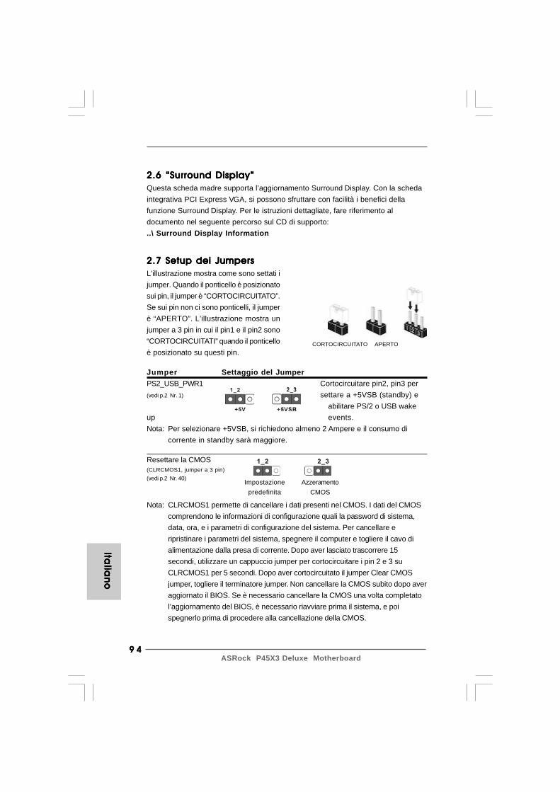
9 49 49 49 49 4ASRock P45X3 Deluxe Motherboard
Italia
no
Italia
no
Italia
no
Italia
no
Italia
no
CORTOCIRCUITATO APERTO
2.7 Setup dei Jumpers2.7 Setup dei Jumpers2.7 Setup dei Jumpers2.7 Setup dei Jumpers2.7 Setup dei JumpersL’illustrazione mostra come sono settati ijumper. Quando il ponticello è posizionatosui pin, il jumper è “CORTOCIRCUITATO”.Se sui pin non ci sono ponticelli, il jumperè “APERTO”. L’illustrazione mostra unjumper a 3 pin in cui il pin1 e il pin2 sono“CORTOCIRCUITATI” quando il ponticelloè posizionato su questi pin.
Jumper Settaggio del JumperPS2_USB_PWR1 Cortocircuitare pin2, pin3 per(vedi p.2 Nr. 1) settare a +5VSB (standby) e
abilitare PS/2 o USB wakeup events.Nota: Per selezionare +5VSB, si richiedono almeno 2 Ampere e il consumo di
corrente in standby sarà maggiore.
Resettare la CMOS(CLRCMOS1, jumper a 3 pin)(vedi p.2 Nr. 40)
Nota: CLRCMOS1 permette di cancellare i dati presenti nel CMOS. I dati del CMOScomprendono le informazioni di configurazione quali la password di sistema,data, ora, e i parametri di configurazione del sistema. Per cancellare eripristinare i parametri del sistema, spegnere il computer e togliere il cavo dialimentazione dalla presa di corrente. Dopo aver lasciato trascorrere 15secondi, utilizzare un cappuccio jumper per cortocircuitare i pin 2 e 3 suCLRCMOS1 per 5 secondi. Dopo aver cortocircuitato il jumper Clear CMOSjumper, togliere il terminatore jumper. Non cancellare la CMOS subito dopo averaggiornato il BIOS. Se è necessario cancellare la CMOS una volta completatol’aggiornamento del BIOS, è necessario riavviare prima il sistema, e poispegnerlo prima di procedere alla cancellazione della CMOS.
AzzeramentoCMOS
Impostazionepredefinita
2.6 “Surround Display”2.6 “Surround Display”2.6 “Surround Display”2.6 “Surround Display”2.6 “Surround Display”Questa scheda madre supporta l’aggiornamento Surround Display. Con la schedaintegrativa PCI Express VGA, si possono sfruttare con facilità i benefici dellafunzione Surround Display. Per le istruzioni dettagliate, fare riferimento aldocumento nel seguente percorso sul CD di supporto:..\ Surround Display Information
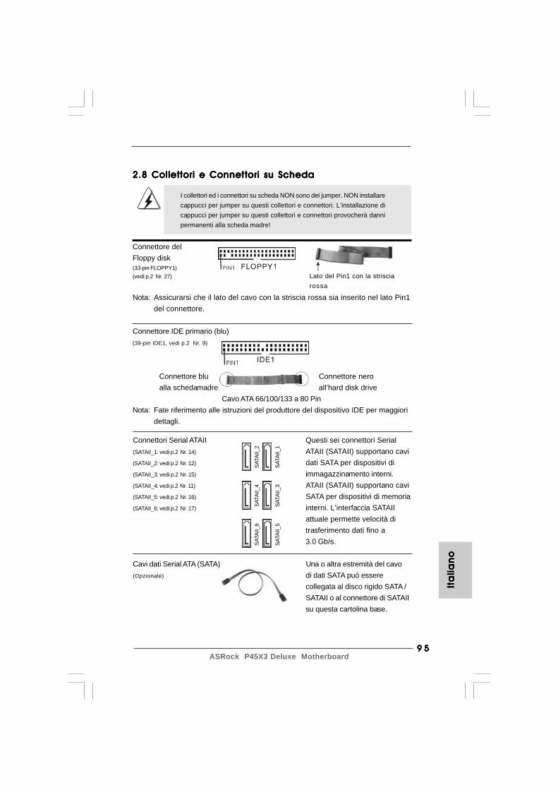
9 59 59 59 59 5ASRock P45X3 Deluxe Motherboard
Cavi dati Serial ATA (SATA) Una o altra estremità del cavo(Opzionale) di dati SATA può essere
collegata al disco rigido SATA /SATAII o al connettore di SATAIIsu questa cartolina base.
Connettori Serial ATAII Questi sei connettori Serial(SATAII_1: vedi p.2 Nr. 14) ATAII (SATAII) supportano cavi(SATAII_2: vedi p.2 Nr. 12) dati SATA per dispositivi di(SATAII_3: vedi p.2 Nr. 15) immagazzinamento interni.(SATAII_4: vedi p.2 Nr. 11) ATAII (SATAII) supportano cavi(SATAII_5: vedi p.2 Nr. 16) SATA per dispositivi di memoria(SATAII_6: vedi p.2 Nr. 17) interni. L’interfaccia SATAII
attuale permette velocità ditrasferimento dati fino a3.0 Gb/s.
Lato del Pin1 con la strisciarossa
2.8 Collettori e Connettori su Scheda2.8 Collettori e Connettori su Scheda2.8 Collettori e Connettori su Scheda2.8 Collettori e Connettori su Scheda2.8 Collettori e Connettori su Scheda
I collettori ed i connettori su scheda NON sono dei jumper. NON installarecappucci per jumper su questi collettori e connettori. L’installazione dicappucci per jumper su questi collettori e connettori provocherà dannipermanenti alla scheda madre!
Connettore delFloppy disk(33-pin FLOPPY1)(vedi p.2 Nr. 27)
Nota: Assicurarsi che il lato del cavo con la striscia rossa sia inserito nel lato Pin1del connettore.
Connettore IDE primario (blu)(39-pin IDE1, vedi p.2 Nr. 9)
Connettore blu Connettore neroalla schedamadre all’hard disk drive
Cavo ATA 66/100/133 a 80 PinNota: Fate riferimento alle istruzioni del produttore del dispositivo IDE per maggiori
dettagli.
Ita
lian
oIt
alia
no
Ita
lian
oIt
alia
no
Ita
lian
o
SATA
II_6
SATA
II_4
SATA
II_2
SATA
II_5
SATA
II_3
SATA
II_1
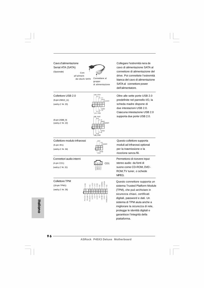
9 69 69 69 69 6ASRock P45X3 Deluxe Motherboard
Italia
no
Italia
no
Italia
no
Italia
no
Italia
no
Collettore USB 2.0 Oltre alle sette porte USB 2.0(9-pin USB10_11) predefinite nel pannello I/O, la(vedi p.2 Nr. 20) scheda madre dispone di
due intestazioni USB 2.0.Ciascuna intestazione USB 2.0supporta due porte USB 2.0.
(9-pin USB8_9)(vedi p.2 Nr. 22)
Collettore modulo infrarossi Questo collettore supporta(5-pin IR1) moduli ad infrarossi optional(vedi p.2 Nr. 34) per la trasmissione e la
ricezione senza fili.
Connettori audio interni Permettono di ricevere input(4-pin CD1) stereo audio da fonti di(vedi p.2 Nr. 31) suono come CD-ROM, DVD -
ROM,TV tuner, o schedeMPEG.
Cavo d’alimentazione Collegare l’estremità nera deSerial ATA (SATA) cavo di alimentazione SATA al(Opzionale) connettore di alimentazione del
drive. Poi connettete l’estremitàbianca del cavo di alimentazioneSATA al connettore powerdell’alimentatore.
Connettereall’ailmentazione
dei dischi SATA Connettere algruppodi alimentazione
CD1
Collettore TPM(19-pin TPM1)
(vedi p.2 Nr. 26)
Questo connettore supporta unsistema Trusted Platform Module(TPM), che può archiviare insicurezza chiavi, certificatidigitali, password e dati. Unsistema di TPM aiuta anche amigliorare la sicurezza di rete,protegge le identità digitali egarantisce l’integrità dellapiattaforma.

9 79 79 79 79 7ASRock P45X3 Deluxe Motherboard
Connettore audio sul È un’interfaccia per il cavo delpannello frontale pannello audio. Che consente(9-pin HD_AUDIO1) connessione facile e controllo(vedi p.2 Nr. 29) dei dispositivi audio.
Ita
lian
oIt
alia
no
Ita
lian
oIt
alia
no
Ita
lian
o
ore supporta unPlatform Modulearchiviare in, certificatid e dati. Unaiuta anche aurezza di rete,tità digitali egrità della
1. La caratteristica HDA (High Definition Audio) supporta il rilevamento dei connettori, però il pannello dei cavi sul telaio deve supportare la funzione HDA (High Definition Audio) per far sì che questa operi in modo corretto. Attenersi alle istruzioni del nostro manuale e del manuale del telaio per installare il sistema.2. Se si utilizza un pannello audio AC’97, installarlo nell’intestazione audio del pannello anteriore, come indicato di seguito: A. Collegare Mic_IN (MIC) a MIC2_L. B. Collegare Audio_R (RIN) a OUT2_R e Audio_L (LIN) ad OUT2_L. C. Collegare Ground (GND) a Ground (GND). D. MIC_RET e OUT_RET sono solo per il pannello audio HD. Non è necessario collegarli per il pannello audio AC’97. E. Entrare nel programma di impostazione BIOS. Entrare su Impostazioni avanzate, quindi selezionare Configurazione chipset. Impostare l’opzione Comando pannello anteriore da [Auto] a [Attivato]. F. Entrare nel sistema di Windows. Fare clic sull’icona situata nell’angolo inferiore destro della barra delle applicazioni per entrare su Realtek HD Audio Manager. Per Windows® 2000 / XP / XP 64-bit OS: Fare clic su “Audio I/O”, selezionare “Impostazioni connettore” ,
scegliere “Disattiva rilevazione presa pannello anteriore” e salvare la modifica facendo clic su “OK”. Per Windows® VistaTM / VistaTM 64-bit OS: Cliccare sull‘icona in alto a destra “Folder” (“Cartella”) ,
selezionare “Disable front panel jack detection” “Disabilitare individuazione presa pannello frontale”) e cliccare “OK” per memorizzare. G. Per attivare il microfono anteriore.
Per il sistema operativo Windows® 2000 / XP / XP 64-bit: Selezionare “Microfono anteriore” come dispositivo predefinito per la registrazione. Per ascoltare la propria voce tramite il microfono anteriore, deselezionare l’icona “Muto” in “Microfono anteriore” di “Riproduzione”. Per il sistema operative Windows® VistaTM / VistaTM 64-bit: Andare alla scheda “Microfono anteriore” nel pannello di controllo d i Realtek. Fare clic su “Imposta dispositivo predefinito” per impostare il microfono anteriore come dispositivo predefinito per la registrazione.
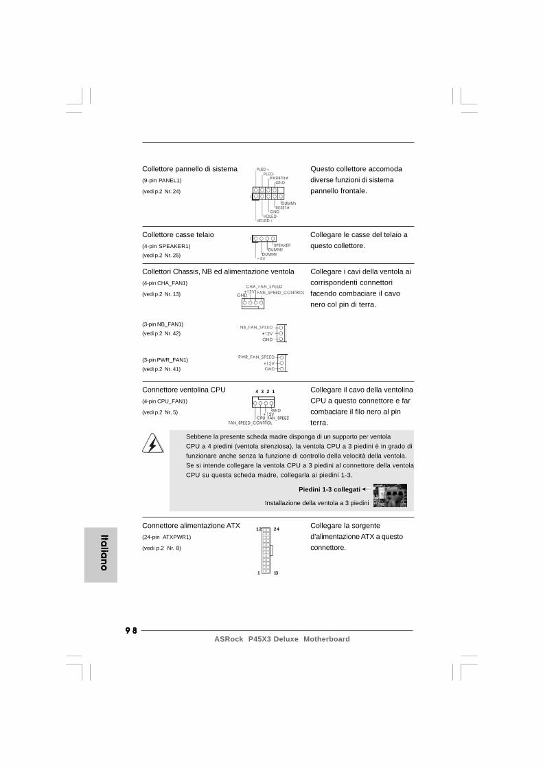
9 89 89 89 89 8ASRock P45X3 Deluxe Motherboard
Italia
no
Italia
no
Italia
no
Italia
no
Italia
no
12
1
24
13
Connettore alimentazione ATX Collegare la sorgente(24-pin ATXPWR1) d’alimentazione ATX a questo(vedi p.2 Nr. 8) connettore.
Sebbene la presente scheda madre disponga di un supporto per ventolaCPU a 4 piedini (ventola silenziosa), la ventola CPU a 3 piedini è in grado difunzionare anche senza la funzione di controllo della velocità della ventola.Se si intende collegare la ventola CPU a 3 piedini al connettore della ventolaCPU su questa scheda madre, collegarla ai piedini 1-3.
Piedini 1-3 collegati
Installazione della ventola a 3 piedini
Connettore ventolina CPU Collegare il cavo della ventolina(4-pin CPU_FAN1) CPU a questo connettore e far(vedi p.2 Nr. 5) combaciare il filo nero al pin
terra.
Collettore casse telaio Collegare le casse del telaio a(4-pin SPEAKER1) questo collettore.(vedi p.2 Nr. 25)
Collettore pannello di sistema Questo collettore accomoda(9-pin PANEL1) diverse funzioni di sistema(vedi p.2 Nr. 24) pannello frontale.
Collettori Chassis, NB ed alimentazione ventola Collegare i cavi della ventola ai(4-pin CHA_FAN1) corrispondenti connettori(vedi p.2 Nr. 13) facendo combaciare il cavo
nero col pin di terra.
(3-pin NB_FAN1)
(vedi p.2 Nr. 42)
(3-pin PWR_FAN1)
(vedi p.2 Nr. 41)
4 3 2 1
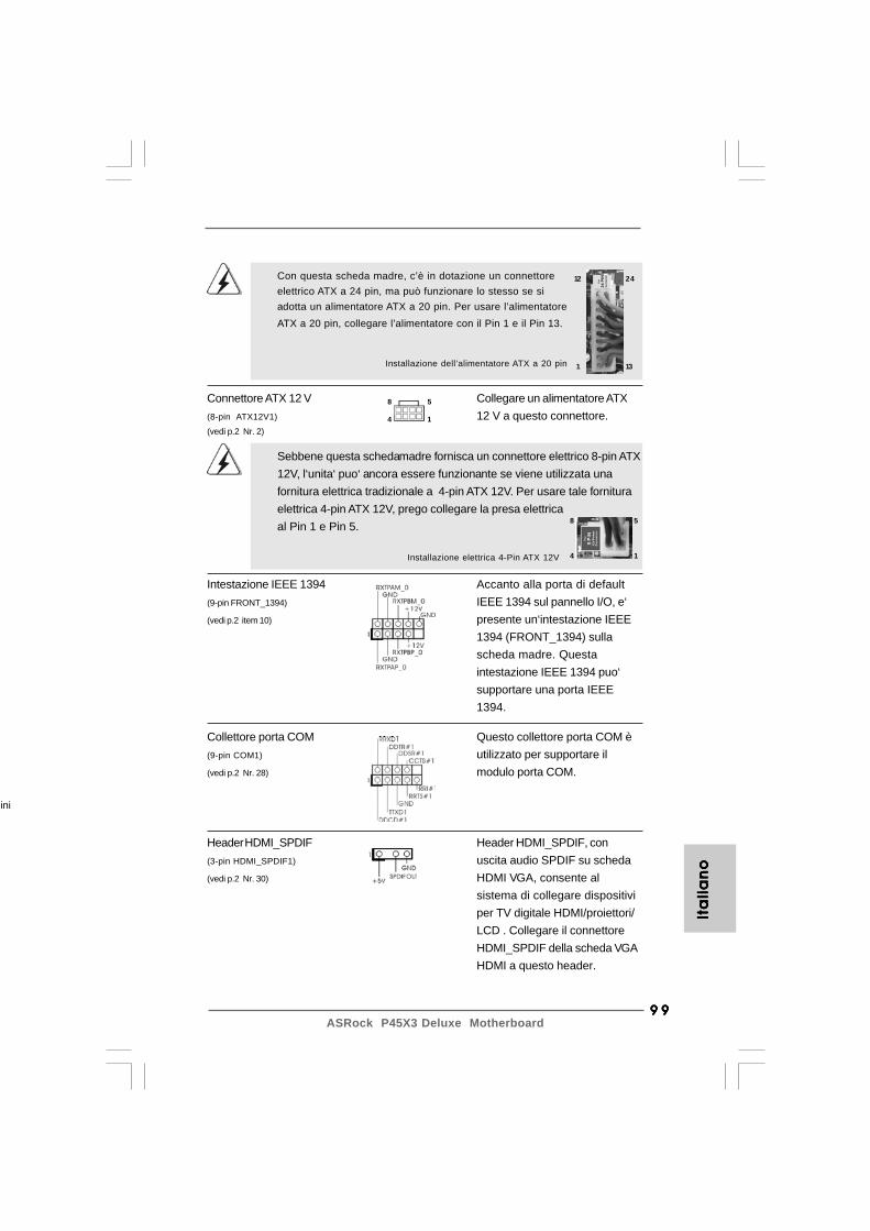
9 99 99 99 99 9ASRock P45X3 Deluxe Motherboard
Ita
lia
no
Ita
lia
no
Ita
lia
no
Ita
lia
no
Ita
lia
no
12
1
24
13Installazione dell’alimentatore ATX a 20 pin
Con questa scheda madre, c’è in dotazione un connettoreelettrico ATX a 24 pin, ma può funzionare lo stesso se siadotta un alimentatore ATX a 20 pin. Per usare l’alimentatoreATX a 20 pin, collegare l’alimentatore con il Pin 1 e il Pin 13.
ini
Sebbene questa schedamadre fornisca un connettore elettrico 8-pin ATX12V, l‘unita‘ puo‘ ancora essere funzionante se viene utilizzata unafornitura elettrica tradizionale a 4-pin ATX 12V. Per usare tale fornituraelettrica 4-pin ATX 12V, prego collegare la presa elettricaal Pin 1 e Pin 5.
Installazione elettrica 4-Pin ATX 12V
Connettore ATX 12 V Collegare un alimentatore ATX(8-pin ATX12V1) 12 V a questo connettore.(vedi p.2 Nr. 2)
Collettore porta COM Questo collettore porta COM è(9-pin COM1) utilizzato per supportare il(vedi p.2 Nr. 28) modulo porta COM.
8 5
4 1
8 5
4 1
Intestazione IEEE 1394 Accanto alla porta di default(9-pin FRONT_1394) IEEE 1394 sul pannello I/O, e‘(vedi p.2 item 10) presente un‘intestazione IEEE
1394 (FRONT_1394) sullascheda madre. Questaintestazione IEEE 1394 puo‘supportare una porta IEEE1394.
Header HDMI_SPDIF Header HDMI_SPDIF, con(3-pin HDMI_SPDIF1) uscita audio SPDIF su scheda(vedi p.2 Nr. 30) HDMI VGA, consente al
sistema di collegare dispositiviper TV digitale HDMI/proiettori/LCD . Collegare il connettoreHDMI_SPDIF della scheda VGAHDMI a questo header.

100100100100100ASRock P45X3 Deluxe Motherboard
Italia
no
Italia
no
Italia
no
Italia
no
Italia
no
CB
A
Cavo HDMI_SPDIF Collegare l’estremità nera (A)(opzionale) del cavo HDMI_SPDIF
all’intestazione HDMI_SPDIFsulla scheda madre. Quindicollegare l’estremità bianca (Bo C) del cavo HDMI_SPDIF alconnettore HDMI_SPDIF dellascheda HDMI VGA.
A. estremità nera B. estremità bianca (2 pin) C. estremità bianca (3 pin)
2.92.92.92.92.9 Interruttori rapidiInterruttori rapidiInterruttori rapidiInterruttori rapidiInterruttori rapidiQuesta scheda madre ha tre interruttori rapidi: Interruttore di alimentazione,interruttore di reset e interruttore pulizia CMOS, che consentono agli utenti diaccendere / spegnere rapidamente o cancellare i valori CMOS.
Interruttore(PWRBTN)(vedi p.2 Nr. 19)
RESET
clr
CMOS
L’interruttore di pulizia CMOS èun interruttore rapido checonsente agli utenti di cancellarevelocemente i valori CMOS.
Interruttore di reset(RSTBTN)(vedi p.2 Nr. 18)
Interruttore pulizia CMOS(CLRCBTN)(vedi p.2 Nr. 17)
L’interruttore di alimentazione èun interruttore rapido checonsente agli utenti diaccendere/spegnererapidamente il sistema.
L’interruttore di reset è uninterruttore rapido che consenteagli utenti di resettarerapidamente il sistema.
Non è consentito usare la funzione Clear CMOS (Cancella CMOS) se siconfigura la password di sistema. Se si vogliono cancellare i valori CMOS,prima è necessario annullare la password di sistema, oppure fare riferimentoalla descrizione della sezione “Jumper Clear CMOS” (Jumper cancella CMOS)a pagina 94.
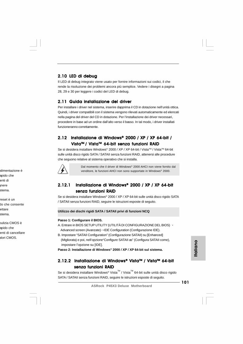
101101101101101ASRock P45X3 Deluxe Motherboard
Ita
lia
no
Ita
lia
no
Ita
lia
no
Ita
lia
no
Ita
lia
no
2.112.112.112.112.11 Guida installazione del driverGuida installazione del driverGuida installazione del driverGuida installazione del driverGuida installazione del driverPer installare i driver nel sistema, inserire dapprima il CD in dotazione nell’unità ottica.Quindi, i driver compatibili con il sistema vengono rilevati automaticamente ed elencatinella pagina del driver del CD in dotazione. Per l’installazione dei driver necessari,procedere in base ad un ordine dall’alto verso il basso. In tal modo, i driver installatifunzioneranno correttamente.
Utilizzo dei dischi rigidi SATA / SATAII privi di funzioni NCQ
Passo 1: Configurare il BIOS.A. Entrare in BIOS SETUP UTILITY (UTILITÀ DI CONFIGURAZIONE DEL BIOS)
Advanced screen (Avanzate) IDE Configuration (Configurazione IDE).B. Impostare “SATAII Configuration” (Configurazione SATAII) su [Enhanced] (Migliorata) e poi, nell’opzione“Configure SATAII as” (Configura SATAII come), impostare l’opzione su [IDE].Passo 2: Installazione di Windows® 2000 / XP / XP 64-bit sul sistema.
2.122.122.122.122.12 Installazione di Windows Installazione di Windows Installazione di Windows Installazione di Windows Installazione di Windows®®®®® 2000 / XP / XP 64-bit / 2000 / XP / XP 64-bit / 2000 / XP / XP 64-bit / 2000 / XP / XP 64-bit / 2000 / XP / XP 64-bit /
Vista Vista Vista Vista VistaTM TM TM TM TM / Vista/ Vista/ Vista/ Vista/ VistaTMTMTMTMTM 64-bit senza funzioni RAID 64-bit senza funzioni RAID 64-bit senza funzioni RAID 64-bit senza funzioni RAID 64-bit senza funzioni RAIDSe si desidera installare Windows® 2000 / XP / XP 64-bit / VistaTM / VistaTM 64-bitsulle unità disco rigido SATA / SATAII senza funzioni RAID, attenersi alle procedureche seguono relative al sistema operativo che si installa.
Dal momento che il driver di Windows® 2000 AHCI non viene fornito dalvenditore, le funzioni AHCI non sono supportate in Windows® 2000.
2.12.1 Installazione di Windows2.12.1 Installazione di Windows2.12.1 Installazione di Windows2.12.1 Installazione di Windows2.12.1 Installazione di Windows®®®®® 2000 / XP / XP 64-bit 2000 / XP / XP 64-bit 2000 / XP / XP 64-bit 2000 / XP / XP 64-bit 2000 / XP / XP 64-bit
senza funzioni RAID senza funzioni RAID senza funzioni RAID senza funzioni RAID senza funzioni RAIDSe si desidera installare Windows® 2000 / XP / XP 64-bit sulle unità disco rigido SATA/ SATAII senza funzioni RAID, seguire le istruzioni esposte di seguito.
2.12.2 Installazione di Windows2.12.2 Installazione di Windows2.12.2 Installazione di Windows2.12.2 Installazione di Windows2.12.2 Installazione di Windows®®®®® Vista Vista Vista Vista VistaTMTMTMTMTM / Vista / Vista / Vista / Vista / VistaTMTMTMTMTM 64-bit 64-bit 64-bit 64-bit 64-bit
senza funzioni RAID senza funzioni RAID senza funzioni RAID senza funzioni RAID senza funzioni RAIDSe si desidera installare Windows® Vista
TM / Vista
TM 64-bit sulle unità disco rigido
SATA / SATAII senza funzioni RAID, seguire le istruzioni esposte di seguito.
pulizia CMOS èapido cheenti di cancellarealori CMOS.
alimentazione èapido cheenti di
gnerestema.
reset è undo che consenteettarestema.
2.102.102.102.102.10 LED di debugLED di debugLED di debugLED di debugLED di debugIl LED di debug integrato viene usato per fornire informazioni sui codici, il cherende la risoluzione dei problemi ancora più semplice. Vedere i disegni a pagina28, 29 e 30 per leggere i codici del LED di debug.

102102102102102ASRock P45X3 Deluxe Motherboard
2.132.132.132.132.13 TTTTTecnologia di Untied Overclockingecnologia di Untied Overclockingecnologia di Untied Overclockingecnologia di Untied Overclockingecnologia di Untied OverclockingQuesta scheda madre supporta la tecnologia Untied Overclocking, in altre parole,durante l’overclocking, FSB ha a disposizione margini migliori grazie ai bus PCI /PCIE fissati. Prima di abilitare la funzione Untied Overclocking inserire l’opzione“Modalità Overclock” nelle impostazioni del BIOS per impostare la selezione da[Auto] a [Manual]. A questo punto, la CPU FSB è “libera” durante l’overclocking, ma ibus PCI / PCIE sono nella modalità fissata in modo tale che l’FSB posa operare sottoun più stabile ambiente di overclocking.
Fare riferimento all’avviso di pagina 84 per i possibili rischi dell’overclockingprima di applicare la tecnologia Untied Overclocking Technology.
Utilizzo dei dischi rigidi SATA / SATAII con funzioni NCQ
Passo 1: Configurare il BIOS.A. Entrare in BIOS SETUP UTILITY (UTILITÀ DI CONFIGURAZIONE DEL BIOS)
Advanced screen (Avanzate) IDE Configuration (Configurazione IDE).B. Impostare “SATAII Configuration” (Configurazione SATAII) su [Enhanced] (Migliorata) e poi, nell’opzione“Configure SATAII as” (Configura SATAII come), impostare l’opzione su [AHCI].Passo 2: Installazione di Windows® VistaTM / VistaTM 64-bit sul sistema.Inserire il disco Windows® VistaTM / VistaTM 64-bit nell’unità ottica per avviare ilsistema, poi seguire le istruzioni per installare il sistema operativo Windows® VistaTM /VistaTM 64-bit sul sistema. Quando si vede la pagina “Where do you want to installWindows?” (Dove si vuole eseguire l’istallazione di Windows), inserire il CD disupporto ASRock nell’unità ottica e fare clic sul pulsante “Carica driver” , in basso asinistra, per caricare i driver Intel® AHCI. I driver Intel® AHCI si trova sul seguentepercorso del CD di supporto:.. \ I386 (per utenti Windows® VistaTM).. \ AMD64 (per utenti Windows® VistaTM 64-bit)Dopodiché, inserire di nuovo il disco Windows® VistaTM / VistaTM 64-bit nell’unità otticaper continuare l’installazione.
Passo 1: Configurare il BIOS.A. Entrare in BIOS SETUP UTILITY (UTILITÀ DI CONFIGURAZIONE DEL BIOS)
Advanced screen (Avanzate) IDE Configuration (Configurazione IDE).B. Impostare “SATAII Configuration” (Configurazione SATAII) su [Enhanced] (Migliorata) e poi, nell’opzione“Configure SATAII as” (Configura SATAII come), impostare l’opzione su [IDE].Passo 2: Installazione di Windows® VistaTM / VistaTM 64-bit sul sistema.
Utilizzo dei dischi rigidi SATA / SATAII privi di funzioni NCQ
Italia
no
Italia
no
Italia
no
Italia
no
Italia
no
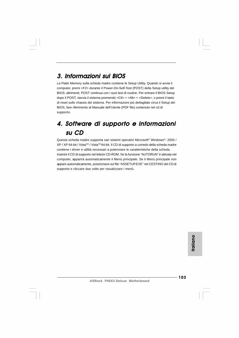
103103103103103ASRock P45X3 Deluxe Motherboard
Ita
lia
no
Ita
lia
no
Ita
lia
no
Ita
lia
no
Ita
lia
no
3. Informazioni sul BIOS3. Informazioni sul BIOS3. Informazioni sul BIOS3. Informazioni sul BIOS3. Informazioni sul BIOSLa Flash Memory sulla scheda madre contiene le Setup Utility. Quando si avvia ilcomputer, premi <F2> durante il Power-On-Self-Test (POST) della Setup utility delBIOS; altrimenti, POST continua con i suoi test di routine. Per entrare il BIOS Setupdopo il POST, riavvia il sistema premendo <Ctl> + <Alt> + <Delete>, o premi il tastodi reset sullo chassis del sistema. Per informazioni più dettagliate circa il Setup delBIOS, fare riferimento al Manuale dell’Utente (PDF file) contenuto nel cd disupporto.
4. Sof4. Sof4. Sof4. Sof4. Software di supportware di supportware di supportware di supportware di supporto e informazionito e informazionito e informazionito e informazionito e informazioni su CD su CD su CD su CD su CDQuesta scheda madre supporta vari sistemi operativi Microsoft® Windows®: 2000 /XP / XP 64-bit / VistaTM / VistaTM 64-bit. Il CD di supporto a corredo della scheda madrecontiene i driver e utilità necessari a potenziare le caratteristiche della scheda.Inserire il CD di supporto nel lettore CD-ROM. Se la funzione “AUTORUN” è attivata nelcomputer, apparirà automaticamente il Menù principale. Se il Menù principale nonappare automaticamente, posizionarsi sul file “ASSETUP.EXE” nel CESTINO del CD disupporto e cliccare due volte per visualizzare i menù.
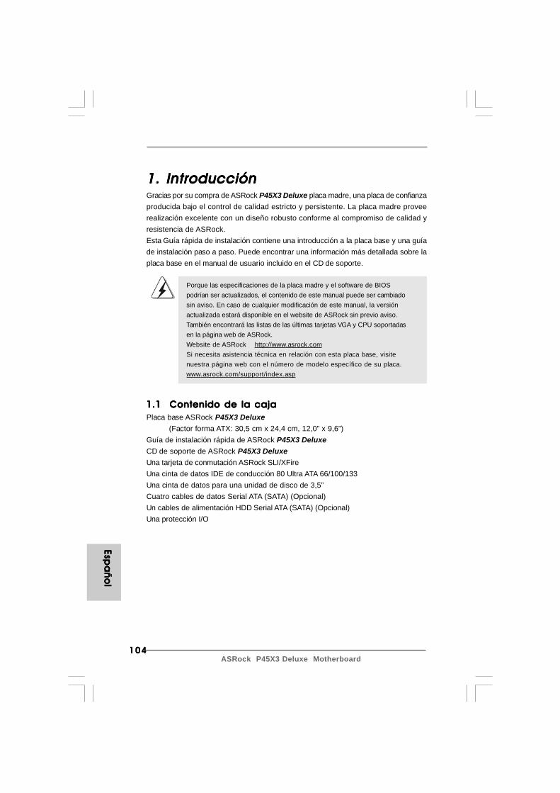
104104104104104ASRock P45X3 Deluxe Motherboard
Espa
ño
lEsp
añ
ol
Espa
ño
lEsp
añ
ol
Espa
ño
l
1. Introducción1. Introducción1. Introducción1. Introducción1. IntroducciónGracias por su compra de ASRock P45X3 Deluxe placa madre, una placa de confianzaproducida bajo el control de calidad estricto y persistente. La placa madre proveerealización excelente con un diseño robusto conforme al compromiso de calidad yresistencia de ASRock.Esta Guía rápida de instalación contiene una introducción a la placa base y una guíade instalación paso a paso. Puede encontrar una información más detallada sobre laplaca base en el manual de usuario incluido en el CD de soporte.
Porque las especificaciones de la placa madre y el software de BIOSpodrían ser actualizados, el contenido de este manual puede ser cambiadosin aviso. En caso de cualquier modificación de este manual, la versiónactualizada estará disponible en el website de ASRock sin previo aviso.También encontrará las listas de las últimas tarjetas VGA y CPU soportadasen la página web de ASRock.Website de ASRock http://www.asrock.comSi necesita asistencia técnica en relación con esta placa base, visitenuestra página web con el número de modelo específico de su placa.www.asrock.com/support/index.asp
1.1 Contenido de la caja1.1 Contenido de la caja1.1 Contenido de la caja1.1 Contenido de la caja1.1 Contenido de la cajaPlaca base ASRock P45X3 Deluxe
(Factor forma ATX: 30,5 cm x 24,4 cm, 12,0” x 9,6”)Guía de instalación rápida de ASRock P45X3 DeluxeCD de soporte de ASRock P45X3 DeluxeUna tarjeta de conmutación ASRock SLI/XFireUna cinta de datos IDE de conducción 80 Ultra ATA 66/100/133Una cinta de datos para una unidad de disco de 3,5”Cuatro cables de datos Serial ATA (SATA) (Opcional)Un cables de alimentación HDD Serial ATA (SATA) (Opcional)Una protección I/O
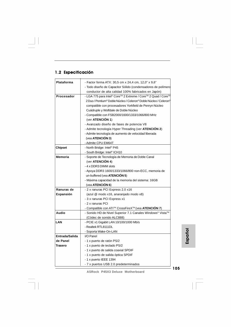
105105105105105ASRock P45X3 Deluxe Motherboard
1.21.21.21.21.2 EspecificaciónEspecificaciónEspecificaciónEspecificaciónEspecificación
Plataforma - Factor forma ATX: 30,5 cm x 24,4 cm, 12,0” x 9,6”- Todo diseño de Capacitor Sólido (condensadores de polímero conductor de alta calidad 100% fabricados en Japón)
Procesador - LGA 775 para Intel® CoreTM 2 Extreme / CoreTM 2 Quad / CoreTM
2 Duo / Pentium® Doble Núcleo / Celeron® Doble Núcleo / Celeron®
compatible con procesadores Yorkfield de Penryn Núcleo Cuádruple y Wolfdale de Doble Núcleo- Compatible con FSB2000/1600/1333/1066/800 MHz (ver ATENCIÓN 1)- Avanzado diseño de fases de potencia V8- Admite tecnología Hyper Threading (ver ATENCIÓN 2)- Admite tecnología de aumento de velocidad liberada
(vea ATENCIÓN 3)- Admite CPU EM64T
Chipset - North Bridge: Intel® P45- South Bridge: Intel® ICH10
Memoria - Soporte de Tecnología de Memoria de Doble Canal (ver ATENCIÓN 4)- 4 x DDR3 DIMM slots- Apoya DDR3 1600/1333/1066/800 non-ECC, memoria de un-buffered (vea ATENCIÓN 5)- Máxima capacidad de la memoria del sistema: 16GB (vea ATENCIÓN 6)
Ranuras de - 2 x ranuras PCI Express 2.0 x16 Expansión (azul @ modo x16, anaranjado modo x8)
- 3 x ranuras PCI Express x1- 2 x ranuras PCI- Compatible con ATITM CrossFireXTM (vea ATENCIÓN 7)
Audio - Sonido HD de Nivel Superior 7.1 Canales Windows® VistaTM
(Códec de sonido ALC888) LAN - PCIE x1 Gigabit LAN 10/100/1000 Mb/s
- Realtek RTL8111DL- Soporta Wake-On-LAN
Entrada/Salida I/O Panel de Panel - 1 x puerto de ratón PS/2 Trasero - 1 x puerto de teclado PS/2
- 1 x puerto de salida coaxial SPDIF- 1 x puerto de salida óptica SPDIF- 1 x puerto IEEE 1394- 7 x puertos USB 2.0 predeterminados
Esp
añ
ol
Esp
añ
ol
Esp
añ
ol
Esp
añ
ol
Esp
añ
ol
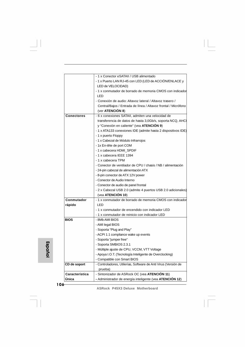
106106106106106ASRock P45X3 Deluxe Motherboard
Espa
ño
lEsp
añ
ol
Espa
ño
lEsp
añ
ol
Espa
ño
l
- 1 x Conector eSATAII / USB alimentado- 1 x Puerto LAN RJ-45 con LED (LED de ACCIÓN/ENLACE y LED de VELOCIDAD)- 1 x conmutador de borrado de memoria CMOS con indicador LED- Conexión de audio: Altavoz lateral / Altavoz trasero / Central/Bajos / Entrada de línea / Altavoz frontal / Micrófono
(ver ATENCIÓN 8) Conectores - 6 x conexiones SATAII, admiten una velocidad de
transferencia de datos de hasta 3,0Gb/s, soporta NCQ, AHCI y “Conexión en caliente” (vea ATENCIÓN 9)- 1 x ATA133 conexiones IDE (admite hasta 2 dispositivos IDE)- 1 x puerto Floppy- 1 x Cabezal de Módulo Infrarrojos- 1x En-tête de port COM- 1 x cabecera HDMI_SPDIF- 1 x cabecera IEEE 1394- 1 x cabecera TPM- Conector de ventilador de CPU / chasis / NB / alimentación- 24-pin cabezal de alimentación ATX- 8-pin conector de ATX 12V power- Conector de Audio Interno- Conector de audio de panel frontal- 2 x Cabezal USB 2.0 (admite 4 puertos USB 2.0 adicionales) (vea ATENCIÓN 10)
Conmutador - 1 x conmutador de borrado de memoria CMOS con indicador rápido LED
- 1 x conmutador de encendido con indicador LED- 1 x conmutador de reinicio con indicador LED
BIOS - 8Mb AMI BIOS- AMI legal BIOS- Soporta “Plug and Play”- ACPI 1.1 compliance wake up events- Soporta “jumper free”- Soporta SMBIOS 2.3.1- Múltiple ajuste de CPU, VCCM, VTT Voltage- Apoya I.O.T. (Tecnología Inteligente de Overclocking)- Compatible con Smart BIOS
CD de soport - Controladores, Utilerías, Software de Anti Virus (Versión de prueba)
Característica - Sintonizador de ASRock OC (vea ATENCIÓN 11) Única - Administrador de energía inteligente (vea ATENCIÓN 12)
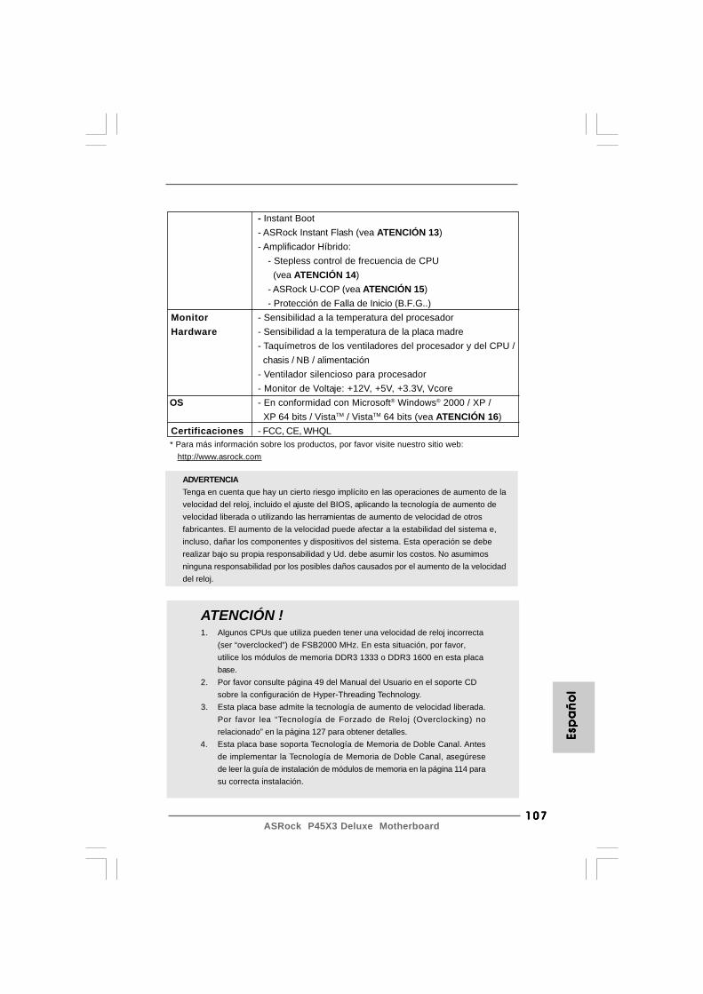
107107107107107ASRock P45X3 Deluxe Motherboard
ADVERTENCIATenga en cuenta que hay un cierto riesgo implícito en las operaciones de aumento de lavelocidad del reloj, incluido el ajuste del BIOS, aplicando la tecnología de aumento develocidad liberada o utilizando las herramientas de aumento de velocidad de otrosfabricantes. El aumento de la velocidad puede afectar a la estabilidad del sistema e,incluso, dañar los componentes y dispositivos del sistema. Esta operación se deberealizar bajo su propia responsabilidad y Ud. debe asumir los costos. No asumimosninguna responsabilidad por los posibles daños causados por el aumento de la velocidaddel reloj.
ATENCIÓN !1. Algunos CPUs que utiliza pueden tener una velocidad de reloj incorrecta
(ser “overclocked”) de FSB2000 MHz. En esta situación, por favor,utilice los módulos de memoria DDR3 1333 o DDR3 1600 en esta placabase.
2. Por favor consulte página 49 del Manual del Usuario en el soporte CDsobre la configuración de Hyper-Threading Technology.
3. Esta placa base admite la tecnología de aumento de velocidad liberada.Por favor lea “Tecnología de Forzado de Reloj (Overclocking) norelacionado” en la página 127 para obtener detalles.
4. Esta placa base soporta Tecnología de Memoria de Doble Canal. Antesde implementar la Tecnología de Memoria de Doble Canal, asegúresede leer la guía de instalación de módulos de memoria en la página 114 parasu correcta instalación.
Esp
añ
ol
Esp
añ
ol
Esp
añ
ol
Esp
añ
ol
Esp
añ
ol
- Instant Boot- ASRock Instant Flash (vea ATENCIÓN 13)- Amplificador Híbrido:
- Stepless control de frecuencia de CPU (vea ATENCIÓN 14)- ASRock U-COP (vea ATENCIÓN 15)- Protección de Falla de Inicio (B.F.G..)
Monitor - Sensibilidad a la temperatura del procesador Hardware - Sensibilidad a la temperatura de la placa madre
- Taquímetros de los ventiladores del procesador y del CPU / chasis / NB / alimentación- Ventilador silencioso para procesador- Monitor de Voltaje: +12V, +5V, +3.3V, Vcore
OS - En conformidad con Microsoft® Windows® 2000 / XP / XP 64 bits / VistaTM / VistaTM 64 bits (vea ATENCIÓN 16)
Certificaciones - FCC, CE, WHQL * Para más información sobre los productos, por favor visite nuestro sitio web: http://www.asrock.com
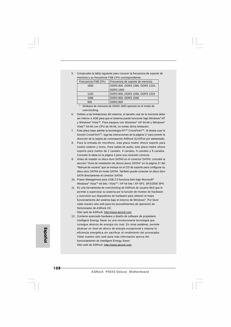
108108108108108ASRock P45X3 Deluxe Motherboard
5. Compruebe la tabla siguiente para conocer la frecuencia de soporte dememoria y su frecuencia FSB CPU correspondiente.
Frecuencia FSB CPU Frecuencia de soporte de memoria1600 DDR3 800, DDR3 1066, DDR3 1333,
DDR3 16001333 DDR3 800, DDR3 1066, DDR3 13331066 DDR3 800, DDR3 1066800 DDR3 800
* Módulos de memoria de DDR3 1600 operará en el modo deoverclocking.
6. Debido a las limitaciones del sistema, el tamaño real de la memoria debeser inferior a 4GB para que el sistema pueda funcionar bajo Windows® XPy Windows® VistaTM. Para equipos con Windows® XP 64-bit y Windows®
VistaTM 64-bit con CPU de 64-bit, no existe dicha limitación.7. Esta placa base admite la tecnología ATITM CrossFireXTM. Si desea usar la
función CrossFireXTM, siga las instrucciones de la página 17 para invertir ladirección de la tarjeta de conmutación ASRock SLI/XFire por adelantado.
8. Para la entrada de micrófono, esta placa madre ofrece soporte paramodos estéreo y mono. Para salida de audio, este placa madre ofrecesoporte para modos de 2 canales, 4 canales, 6 canales y 8 canales.Consulte la tabla en la página 3 para una conexión correcta.
9. Antes de instalar un disco duro SATAII en el conector SATAII, consulte lasección “Guía de instalación de discos duros SATAII” en la página 37 del“Manual de usuario” que se incluye en el CD de soporte para configurar sudisco duro SATAII en modo SATAII. También puede conectar un disco duroSATA directamente al conector SATAII.
10. Power Management para USB 2.0 funciona bien bajo Microsoft®
Windows® VistaTM 64 bits / VistaTM / XP 64 bits / XP SP1; SP2/2000 SP4.11. Es una herramienta de overclocking de ASRock de usuario-fácil que le
permite a supervisar su sistema por la función de monitor de hardwarey overclock sus dispositivos de hardware para obtener el mejorfuncionamiento del sistema bajo el entorno de Windows®. Por favorvisite nuestro sitio web para los procedimientos de operación deSintonizador de ASRock OC.Sitio web de ASRock: http://www.asrock.com
12. Contiene avanzado hardware y diseño de software de propietario.Intelligent Energy Saver es una revolucionaria tecnología queconsigue ahorros de energía sin rival. En otras palabras, permitealcanzar un nivel de ahorro de energía excepcional y mejorar laeficiencia energética sin sacrificar el rendimiento del procesador.Visite nuestro sitio web para más información acerca delfuncionamiento de Intelligent Energy Saver.Sitio web de ASRock: http://www.asrock.com
Espa
ño
lEsp
añ
ol
Espa
ño
lEsp
añ
ol
Espa
ño
l
109109109109109ASRock P45X3 Deluxe Motherboard
13. ASRock Instant Flash es una utilidad de programación del BIOS que seencuentra almacenada en la memoria Flash ROM. Esta sencilla herramientade actualización de BIOS le permitirá actualizar el BIOS del sistema sinnecesidad de acceder a ningún sistema operativo, como MS-DOS oWindows®. Gracias a esta utilidad, sólo necesitará pulsar <F6> durante lafase POST o pulsar <F2> para acceder al menú de configuración del BIOSy a la utilidad ASRock Instant Flash. Ejecute esta herramienta y guarde elarchivo correspondiente al sistema BIOS nuevo en su unidad flash USB,unidad de disco flexible o disco duro para poder actualizar el BIOS con sólopulsar un par de botones, sin necesidad de preparar un disco flexibleadicional ni utilizar complicadas utilidades de programación. Recuerde quela unidad flash USB o disco duro utilizado debe disponer del sistema dearchivos FAT32/16/12.
14. Aunque esta placa base ofrece un control complete, no es recomendableforzar la velocidad. Las frecuencias de bus de la CPU distintas a lasrecomendadas pueden causar inestabilidad en el sistema o dañar la CPU.
15. Cuando la temperatura de CPU está sobre-elevada, el sistema va aapagarse automaticamente. Antes de reanudar el sistema, compruebe siel ventilador de la CPU de la placa base funcionaapropiadamente y desconecte el cable de alimentación, a continuación,vuelva a conectarlo. Para mejorar la disipación de calor, acuérdese deaplicar thermal grease entre el procesador y el disipador de calor cuandousted instala el sistema de PC.
16. Las funciones de AHCI no son compatibles con Windows® 2000 OS. Serecomienda utilizar el modo IDE con Windows® 2000. Por favor,consulte la página 59 del “Manual del Usuario” en el CD de soporte parauna configuración más detallada.
Esp
añ
ol
Esp
añ
ol
Esp
añ
ol
Esp
añ
ol
Esp
añ
ol
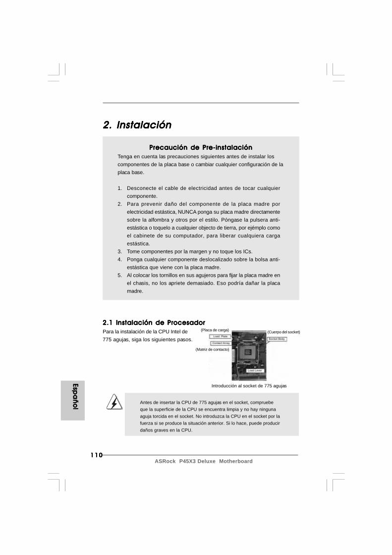
110110110110110ASRock P45X3 Deluxe Motherboard
2. Instalación2. Instalación2. Instalación2. Instalación2. Instalación
Precaución de Pre-instalaciónPrecaución de Pre-instalaciónPrecaución de Pre-instalaciónPrecaución de Pre-instalaciónPrecaución de Pre-instalaciónTenga en cuenta las precauciones siguientes antes de instalar loscomponentes de la placa base o cambiar cualquier configuración de laplaca base.
1. Desconecte el cable de electricidad antes de tocar cualquiercomponente.
2. Para prevenir daño del componente de la placa madre porelectricidad estástica, NUNCA ponga su placa madre directamentesobre la alfombra y otros por el estilo. Póngase la pulsera anti-estástica o toquelo a cualquier objecto de tierra, por ejémplo comoel cabinete de su computador, para liberar cualquiera cargaestástica.
3. Tome componentes por la margen y no toque los ICs.4. Ponga cualquier componente deslocalizado sobre la bolsa anti-
estástica que viene con la placa madre.5. Al colocar los tornillos en sus agujeros para fijar la placa madre en
el chasis, no los apriete demasiado. Eso podría dañar la placamadre.
2.1 Instalación de Procesador2.1 Instalación de Procesador2.1 Instalación de Procesador2.1 Instalación de Procesador2.1 Instalación de ProcesadorPara la instalación de la CPU Intel de775 agujas, siga los siguientes pasos.
Antes de insertar la CPU de 775 agujas en el socket, compruebeque la superficie de la CPU se encuentra limpia y no hay ningunaaguja torcida en el socket. No introduzca la CPU en el socket por lafuerza si se produce la situación anterior. Si lo hace, puede producirdaños graves en la CPU.
Introducción al socket de 775 agujas
(Placa de carga)
(Matriz de contacto)
(Cuerpo del socket)
Espa
ño
lEsp
añ
ol
Espa
ño
lEsp
añ
ol
Espa
ño
l
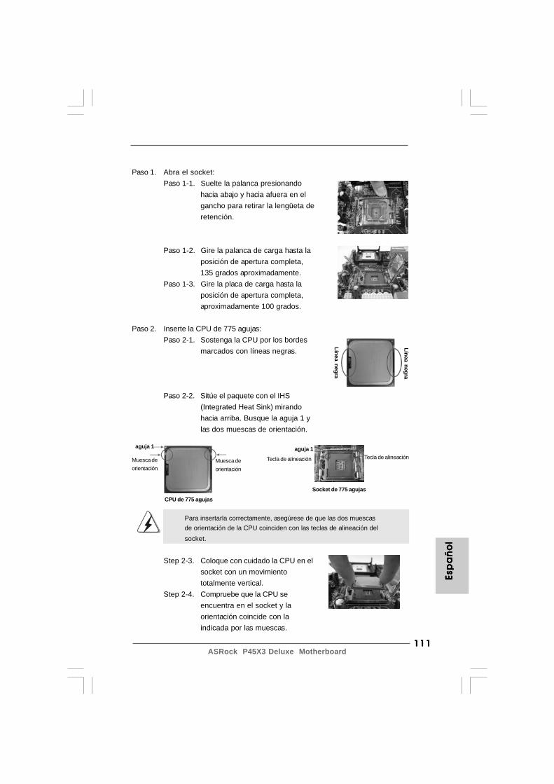
111111111111111ASRock P45X3 Deluxe Motherboard
Paso 1. Abra el socket:Paso 1-1. Suelte la palanca presionando
hacia abajo y hacia afuera en elgancho para retirar la lengüeta deretención.
Paso 1-2. Gire la palanca de carga hasta laposición de apertura completa,135 grados aproximadamente.
Paso 1-3. Gire la placa de carga hasta laposición de apertura completa,aproximadamente 100 grados.
Paso 2. Inserte la CPU de 775 agujas:Paso 2-1. Sostenga la CPU por los bordes
marcados con líneas negras.
Paso 2-2. Sitúe el paquete con el IHS(Integrated Heat Sink) mirandohacia arriba. Busque la aguja 1 ylas dos muescas de orientación.
Para insertarla correctamente, asegúrese de que las dos muescasde orientación de la CPU coinciden con las teclas de alineación delsocket.
Step 2-3. Coloque con cuidado la CPU en elsocket con un movimientototalmente vertical.
Step 2-4. Compruebe que la CPU seencuentra en el socket y laorientación coincide con laindicada por las muescas.
Línea negra
Socket de 775 agujas
aguja 1
Tecla de alineaciónMuesca deorientación
Muesca deorientación
CPU de 775 agujas
Línea negra
aguja 1
Tecla de alineaciónEs
pa
ño
lEs
pa
ño
lEs
pa
ño
lEs
pa
ño
lEs
pa
ño
l
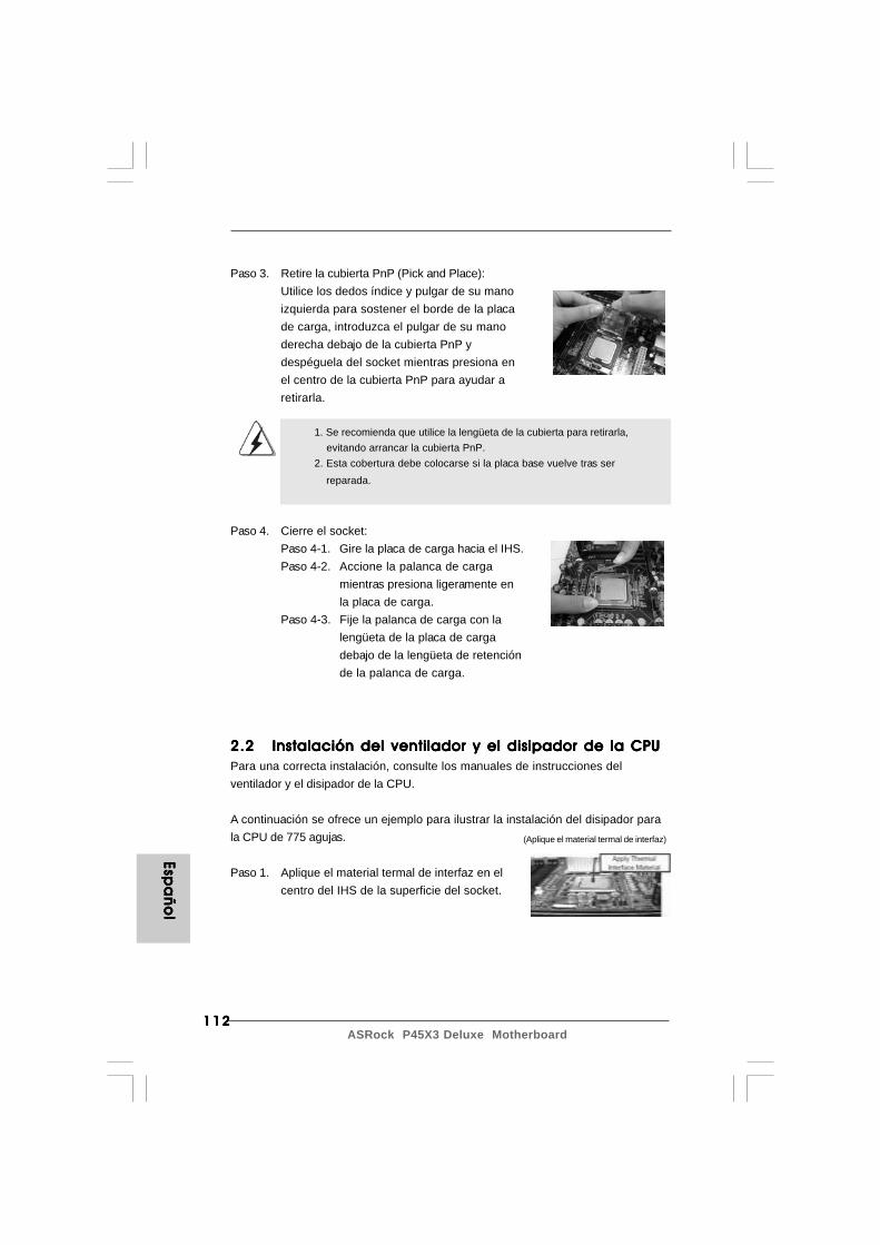
112112112112112ASRock P45X3 Deluxe Motherboard
Espa
ño
lEsp
añ
ol
Espa
ño
lEsp
añ
ol
Espa
ño
l
Paso 3. Retire la cubierta PnP (Pick and Place):Utilice los dedos índice y pulgar de su manoizquierda para sostener el borde de la placade carga, introduzca el pulgar de su manoderecha debajo de la cubierta PnP ydespéguela del socket mientras presiona enel centro de la cubierta PnP para ayudar aretirarla.
1. Se recomienda que utilice la lengüeta de la cubierta para retirarla, evitando arrancar la cubierta PnP.2. Esta cobertura debe colocarse si la placa base vuelve tras ser reparada.
Paso 4. Cierre el socket:Paso 4-1. Gire la placa de carga hacia el IHS.Paso 4-2. Accione la palanca de carga
mientras presiona ligeramente enla placa de carga.
Paso 4-3. Fije la palanca de carga con lalengüeta de la placa de cargadebajo de la lengüeta de retenciónde la palanca de carga.
2.22.22.22.22.2 Instalación del ventilador y el disipador de la CPUInstalación del ventilador y el disipador de la CPUInstalación del ventilador y el disipador de la CPUInstalación del ventilador y el disipador de la CPUInstalación del ventilador y el disipador de la CPUPara una correcta instalación, consulte los manuales de instrucciones delventilador y el disipador de la CPU.
A continuación se ofrece un ejemplo para ilustrar la instalación del disipador parala CPU de 775 agujas.
Paso 1. Aplique el material termal de interfaz en elcentro del IHS de la superficie del socket.
(Aplique el material termal de interfaz)

113113113113113ASRock P45X3 Deluxe Motherboard
(Cables del ventilador en el lado máspróximo al cabezal de la placa madre)
(Ranuras de cierre orientadas al exterior)
(Pulse (4 lugares))
Paso 2. Coloque el disipador en el socket. Asegúresede que los cables del ventilador estánorientados hacia el lado más cercano delconector del ventilador de la CPU en la placamadre (CPU_FAN1, ver página 2, nº 5).
Paso 3. Alinee los cierres con los agujeros de laplaca madre.
Paso 4. Gire el cierre en la dirección de las agujas delreloj y, a continuación, presione las cubiertasdel cierre con el dedo pulgar para instalar ybloquear. Repita el proceso con los cierresrestantes.
Si presiona los cierres sin girarlos en el sentido de las agujas delreloj, el disipador no se podrá fijar a la placa madre.
Paso 5. Conecte el cabezal del ventilador con elconector del ventilador de la CPU en la placamadre.
Paso 6. Fije el cable que sobre con un lazo paraasegurarse de que el cable no interfiere en elfuncionamiento del ventilador y tampoco entraen contacto con otros componentes.
Esp
añ
ol
Esp
añ
ol
Esp
añ
ol
Esp
añ
ol
Esp
añ
ol
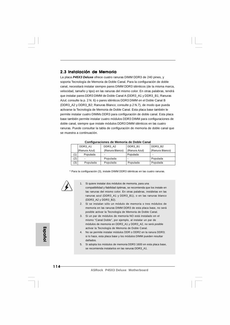
114114114114114ASRock P45X3 Deluxe Motherboard
Espa
ño
lEsp
añ
ol
Espa
ño
lEsp
añ
ol
Espa
ño
l
2.3 Instalación de Memoria2.3 Instalación de Memoria2.3 Instalación de Memoria2.3 Instalación de Memoria2.3 Instalación de MemoriaLa placa P45X3 Deluxe ofrece cuatro ranuras DIMM DDR3 de 240 pines, ysoporta Tecnología de Memoria de Doble Canal. Para la configuración de doblecanal, necesitará instalar siempre pares DIMM DDR3 idénticos (de la misma marca,velocidad, tamaño y tipo) en las ranuras del mismo color. En otras palabras, tendráque instalar pares DDR3 DIMM de Doble Canal A (DDR3_A1 y DDR3_B1; RanurasAzul; consulte la p. 2 N. 6) o pares idénticos DDR3 DIMM en el Doble Canal B(DDR3_A2 y DDR3_B2; Ranuras Blanco; consulte p.2 N.7), de modo que puedaactivarse la Tecnología de Memoria de Doble Canal. Esta placa base también lepermite instalar cuatro DIMMs DDR3 para configuración de doble canal. Esta placabase también permite instalar cuatro módulos DDR3 DIMM para configuraciones dedoble canal, siempre que instale módulos DDR3 DIMM idénticos en las cuatroranuras. Puede consultar la tabla de configuración de memoria de doble canal quese muestra a continuación.
Configuraciones de Memoria de Doble Canal DDR3_A1 DDR3_A2 DDR3_B1 DDR3_B2 (Ranura Azul) (Ranura Blanco) (Ranura Azul) (Ranura Blanco)(1) Populada - Populada -(2) - Populada - Populada(3) Populada Populada Populada Populada
* Para la configuración (3), instale DIMM DDR3 idénticas en las cuatro ranuras.
1. Si quiere instalar dos módulos de memoria, para unacompatibilidad y fiabilidad óptimas, se recomienda que los instale enlas ranuras del mismo color. En otras palabras, instálelas en lasranuras azul (DDR3_A1 y DDR3_B1), o en las ranuras blanco(DDR3_A2 y DDR3_B2).
2. Si se instalan sólo un módulo de memoria o tres módulos dememoria en las ranuras DIMM DDR3 de esta placa base, no seráposible activar la Tecnología de Memoria de Doble Canal.
3. Si un par de módulos de memoria NO está instalado en elmismo “Canal Doble”, por ejemplo, al instalar un par demódulos de memoria en DDR3_A1 y DDR3_A2, no será posibleactivar la Tecnología de Memoria de Doble Canal.
4. No se permite instalar módulos DDR o DDR2 en la ranura DDR3;si lo hace, esta placa base y los módulos DIMM pueden resultardañados.
5. Si adopta los módulos de memoria DDR3 1600 en esta placa base,se recomienda instalarlos en las ranuras DDR3_A1.

115115115115115ASRock P45X3 Deluxe Motherboard
Instalación de una DIMMInstalación de una DIMMInstalación de una DIMMInstalación de una DIMMInstalación de una DIMM
Asegúrese de desconectar la fuente de alimentación antes de añadir oretirar módulos DIMM o componentes del sistema.
Paso 1. Empuje los clips blancos de retención por el extremo de cada lado de laranura de memoria.
Paso 2. Encaje la muesca del DIMM hacia la cumbrera de la ranura.
DIMM ajusta solamente en una dirección. Si fuerza la DIMM en laranura con una orientación incorrecta, provocará daños permanentesen la placa base y en la DIMM.
Paso 3. Inserte la DIMM con firmeza dentro de la ranura hasta que los clips desujeción de ambos lados queden completamente introducidos en su sitio yla DIMM se haya asentado apropiadamente.
Esp
añ
ol
Esp
añ
ol
Esp
añ
ol
Esp
añ
ol
Esp
añ
ol

116116116116116ASRock P45X3 Deluxe Motherboard
Espa
ño
lEsp
añ
ol
Espa
ño
lEsp
añ
ol
Espa
ño
l
2.42.42.42.42.4 Ranuras de Expansión (ranuras PCI y ranuras PCIRanuras de Expansión (ranuras PCI y ranuras PCIRanuras de Expansión (ranuras PCI y ranuras PCIRanuras de Expansión (ranuras PCI y ranuras PCIRanuras de Expansión (ranuras PCI y ranuras PCI
Express)Express)Express)Express)Express)La placa madre P45X3 Deluxe cuenta con 2 ranuras PCI y 5 ranuras PCI Express.Ranura PCI: Para instalar tarjetas de expansión que tienen 32-bit Interface PCI.Ranura PCI Express:
La ranura PCIE1 / PCIE3 / PCIE4 (ranura PCIE x1, Blanca)se utiliza contarjetas PCI Express con ancho de bandax1, como las tarjetas Gigabit LAN, y SATA2.La ranura PCIE2 (ranura PCIE x16, Azul) se utiliza contarjetas PCI Express con ancho de banda x16, o parainstalar tarjetas gráficas PCI Express compatibles con lafunción CrossFireXTM.La ranura PCIE5 (ranura PCIE x16, Anaranjado) se utilizacon tarjetas PCI Express con ancho de banda x1, comolas tarjetas Gigabit LAN, SATA2, etc., o para instalartarjetas gráficas PCI Express compatibles con la funciónCrossFireXTM.
Configuración de las ranuras para tarjetas conmutadorasSLI/XFire en PCIE2 / PCIE5
Ranura PCIE2 Ranura PCIE5 Ranura de retención de (azul) (anaranjado) tarjetas conmutadoras
SLI/XFire Tarjeta gráfica sencilla PCIE x16 N/A
Tarjeta gráfica doble PCIE x8 PCIE x8 con Modo CrossFireXTM
(Por Defecto)
117117117117117ASRock P45X3 Deluxe Motherboard
2.5 Manual de uso de CrossFireX2.5 Manual de uso de CrossFireX2.5 Manual de uso de CrossFireX2.5 Manual de uso de CrossFireX2.5 Manual de uso de CrossFireXTMTMTMTMTM
Esta placa base es compatible con la función CrossFireXTM. La tecnologíaCrossFireXTM ofrece los medios más avanzados disponibles para combinar variasunidades de procesado gráfico (GPU) de alto rendimiento en un solo PC.Combinando una amplia gama de modos de funcionamiento diferentes con undiseño software inteligente y un innovador mecanismo de interconexión,CrossFireXTM permite disfrutar del nivel de rendimiento más alto posible y lasimágenes de mayor calidad en cualquier aplicación 3D. Actualmente, CrossFireXTM
es compatible con los sistemas operativos Windows® XP con Service Pack 2 yVistaTM. Consulte el sitio web de AMD para más información acerca de lasactualizaciones de controladores ATITM CrossFireXTM. Para más información acercade procedimientos de uso y tarjetas gráficas PCI Express compatibles, consulte lapágina 16.
1. Si desea instalar sólo una tarjeta PCI Express VGA en esta placa base, instálela en la ranura PCIE2 (Azul). Así no necesitará ajustar la configuración predeterminada de la tarjeta conmutadora SLI/XFire. No extraiga ni pierda la tarjeta conmutadora ASRock SLI/XFire si funciona correctamente.2. Para obtener información de las tarjetas VGA CrossFireXTM Mode PCI Express y de los procedimientos de instalación de CrossFireXTM, consulte la “Guía de funcionamiento CrossFireXTM” en la página 16.
Instalación de TInstalación de TInstalación de TInstalación de TInstalación de Tarjetas de Expansiónarjetas de Expansiónarjetas de Expansiónarjetas de Expansiónarjetas de ExpansiónPaso 1. Antes de instalar la tarjeta de expansión, asegúrese de que la fuente de
alimentación está apagada o el cable de alimentación desconectado. Lea ladocumentación que acompaña a la tarjeta de expansión y realice lasconfiguraciones de hardware necesarias para la tarjeta antes de iniciar lainstalación.
Paso 2. Quite la tapa que corresponde a la ranura que desea utilizar.Paso 3. Encaje el conector de la tarjeta a la ranura. Empuje firmemente la tarjeta en
la ranura.Paso 4. Asegure la tarjeta con tornillos.
Esp
añ
ol
Esp
añ
ol
Esp
añ
ol
Esp
añ
ol
Esp
añ
ol

118118118118118ASRock P45X3 Deluxe Motherboard
Espa
ño
lEsp
añ
ol
Espa
ño
lEsp
añ
ol
Espa
ño
l
Short Open
2.7 Setup de Jumpers2.7 Setup de Jumpers2.7 Setup de Jumpers2.7 Setup de Jumpers2.7 Setup de JumpersLa siguiente ilustración muestra setup deJumpers. Cuando el jumper cap está colocadosobre los pins, el jumper está “SHORT”. Siningun jumper cap está colocado sobre los pins,el jumper está “OPEN”. La ilustración muestraun jumper de 3-pin cuyo pin1 y pin2 están“SHORT” cuando el jumper cap está colocadosobre estes 2 pins.
Jumper Setting DescripciónPS2_USB_PWR1 Ponga en cortocircuito pin 2,(vea p.2, N. 1) pin 3 para habilitar +5VSB
(standby) para PS/2 o USBwake up events.
Atención: Para elegir +5VSB, se necesita corriente mas que 2 Amp proveida por lafuente de electricidad.
Limpiar CMOS(CLRCMOS1, jumper de 3 pins)
(vea p.2, N. 40)
Atención: CLRCMOS1 permite que Usted limpie los datos en CMOS. Los datos enCMOS incluyen informaciones de la configuración del sistema, tales comola contraseña del sistema, fecha, tiempo, y parámetros de la configuracióndel sistema. Para limpiar y reconfigurar los parametros del sistema a laconfiguración de la fábrica, por favor apague el computador y desconecte elcable de la fuente de electricidad, utilice una cubierta de jumper para aislarlas agujas pin2 y pin3 en CLRCMOS1 durante 5 segundos. Por favor acuérdasede quitar el jumper cap después de limpiar el COMS. Por favor acuérdase dequitar el jumper cap después de limpiar el COMS. Si necesita borrar laCMOS cuando acabe de finalizar la actualización de la BIOS, debe arrancarprimero el sistema y, a continuación, apagarlo antes de realizar la acción deborrado de CMOS.
Valorpredeterminado
Restablecimientode la CMOS
2.6 “Surround Display”2.6 “Surround Display”2.6 “Surround Display”2.6 “Surround Display”2.6 “Surround Display”Esta placa base soporta la actualización Surround Display . Con la tarjeta PCIExpress VGA puede disfrutar fácilmente de la función Surround Display. Paraobtener instrucciones detalladas, consulte el documento en la siguiente ruta delCD de soporte: ..\ Surround Display Information
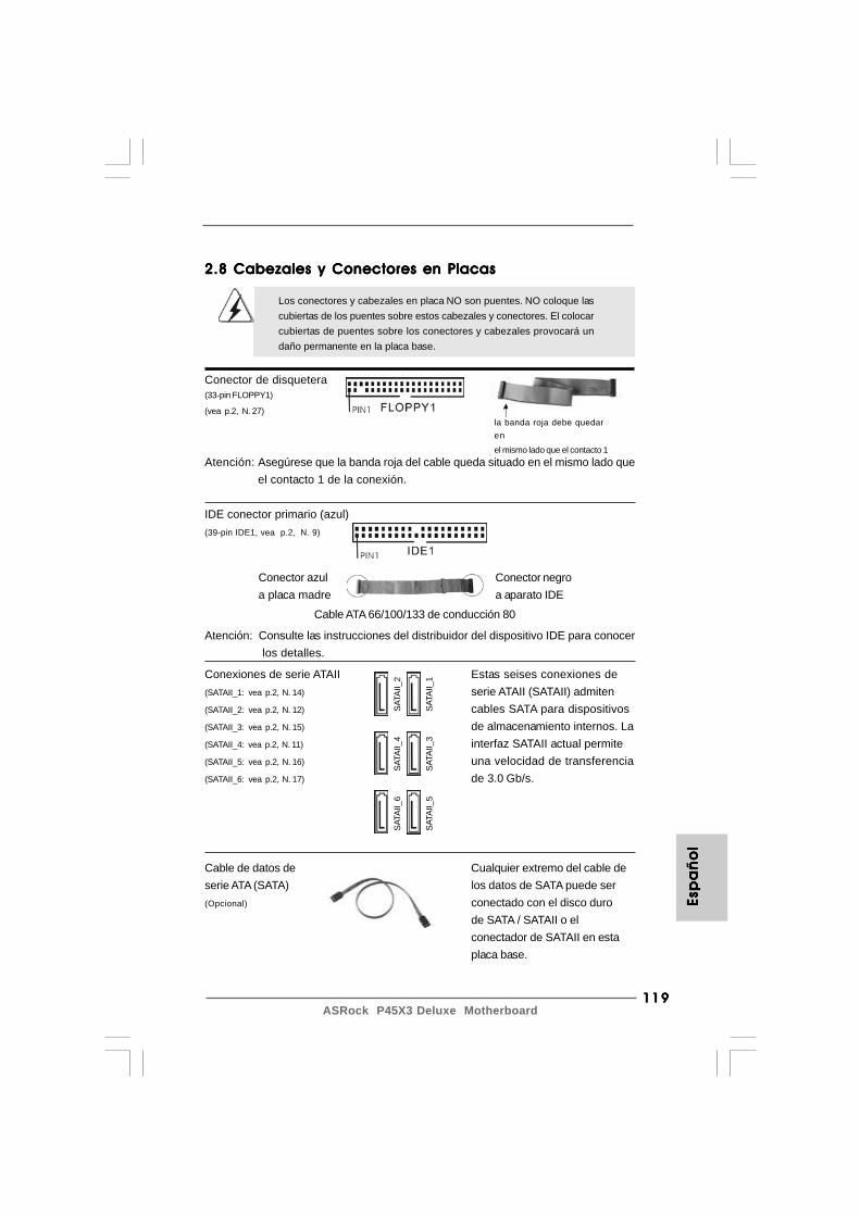
119119119119119ASRock P45X3 Deluxe Motherboard
Esp
añ
ol
Esp
añ
ol
Esp
añ
ol
Esp
añ
ol
Esp
añ
ol
Conector azula placa madre
Conector negroa aparato IDE
la banda roja debe quedaren
el mismo lado que el contacto 1
2.8 Cabezales y Conectores en Placas2.8 Cabezales y Conectores en Placas2.8 Cabezales y Conectores en Placas2.8 Cabezales y Conectores en Placas2.8 Cabezales y Conectores en Placas
Los conectores y cabezales en placa NO son puentes. NO coloque lascubiertas de los puentes sobre estos cabezales y conectores. El colocarcubiertas de puentes sobre los conectores y cabezales provocará undaño permanente en la placa base.
Conector de disquetera(33-pin FLOPPY1)
(vea p.2, N. 27)
Atención: Asegúrese que la banda roja del cable queda situado en el mismo lado queel contacto 1 de la conexión.
IDE conector primario (azul)(39-pin IDE1, vea p.2, N. 9)
Atención: Consulte las instrucciones del distribuidor del dispositivo IDE para conocer los detalles.
Cable ATA 66/100/133 de conducción 80
Cable de datos de Cualquier extremo del cable deserie ATA (SATA) los datos de SATA puede ser(Opcional) conectado con el disco duro
de SATA / SATAII o elconectador de SATAII en estaplaca base.
Conexiones de serie ATAII Estas seises conexiones de(SATAII_1: vea p.2, N. 14) serie ATAII (SATAII) admiten(SATAII_2: vea p.2, N. 12) cables SATA para dispositivos(SATAII_3: vea p.2, N. 15) de almacenamiento internos. La(SATAII_4: vea p.2, N. 11) interfaz SATAII actual permite(SATAII_5: vea p.2, N. 16) una velocidad de transferencia(SATAII_6: vea p.2, N. 17) de 3.0 Gb/s.
SATA
II_6
SATA
II_4
SATA
II_2
SATA
II_5
SATA
II_3
SATA
II_1

120120120120120ASRock P45X3 Deluxe Motherboard
Espa
ño
lEsp
añ
ol
Espa
ño
lEsp
añ
ol
Espa
ño
l
Cabezal USB 2.0 Además de siete puertos(9-pin USB10_11) USB 2.0 predeterminados en el(vea p.2, N. 20) panel de E/S, hay dos bases
de conexiones USB 2.0 en esta placa base. Cada una de
estas bases de conexiones(9-pin USB8_9) admite dos puertos USB 2.0.(vea p.2, N. 22)
Cabezal de Módulo Infrarrojos Este cabezal soporta un(5-pin IR1) módulo infrarrojos de(vea p.2, N. 34) transmisión y recepción
wireless opcional.
Conector de audio interno Permite recepción de input(4-pin CD1) audio de fuente sónica como CD-(vea p.2, N. 31) ROM, DVD-ROM, TV tuner, o
tarjeta MPEG.
Connettereall’ailmentazione
dei dischi SATA Connettere algruppodi alimentazione
Cable de alimentación Conecte el extremo negro del deserie ATA (SATA) cable de SATA al conector de(Opcional) energía de la unidad. A
continuación, conecte elextremo blanco del cable dealimentación SATA a laconexión de alimentación de lafuente de alimentación.
CD1
Cabecera TPM(19-pin TPM1)
(vea p.2, N. 26)
Este conector admite sistemasbasados en Trusted PlatformModule (TPM, Módulo deplataforma segura), quepermiten almacenar claves,certificados digitales,contraseñas y datos conseguridad. Los sistemas TPMtambién mejoran la seguridad dela red, protegen las identidadesdigitales y garantizan laintegridad de la plataforma.
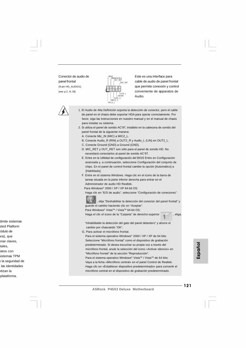
121121121121121ASRock P45X3 Deluxe Motherboard
Esp
añ
ol
Esp
añ
ol
Esp
añ
ol
Esp
añ
ol
Esp
añ
ol
Conector de audio de Este es una interface parapanel frontal cable de audio de panel frontal(9-pin HD_AUDIO1) que permite conexión y control(vea p.2, N. 29) conveniente de apparatos de
Audio.
dmite sistemassted Platformódulo de
ura), queenar claves,tales,
datos consistemas TPMn la seguridad de las identidades
ntizan laplataforma.
1. El Audio de Alta Definición soporta la detección de conector, pero el cable de panel en el chasis debe soportar HDA para operar correctamente. Por favor, siga las instrucciones en nuestro manual y en el manual de chasis para instalar su sistema.2. Si utiliza el panel de sonido AC’97, instálelo en la cabecera de sonido del panel frontal de la siguiente manera: A. Conecte Mic_IN (MIC) a MIC2_L. B. Conecte Audio_R (RIN) a OUT2_R y Audio_L (LIN) en OUT2_L. C. Conecte Ground (GND) a Ground (GND). D. MIC_RET y OUT_RET son sólo para el panel de sonido HD. No necesitará conectarlos al panel de sonido AC’97. E. Entre en la Utilidad de configuración del BIOS Entre en Configuración avanzada y, a continuación, seleccione Configuración del conjunto de chips. En el panel de control frontal cambie la opción [Automático] a [Habilitado]. F. Entre en el sistema Windows. Haga clic en el icono de la barra de tareas situada en la parte inferior derecha para entrar en el Administrador de audio HD Realtek. Para Windows® 2000 / XP / XP 64-bit OS: Haga clic en “E/S de audio”, seleccione “Configuración de conectores”
, elija “Deshabilitar la detección del conector del panel frontal” y guarde el cambio haciendo clic en “Aceptar”. Para Windows® VistaTM / VistaTM 64-bit OS: Haga el clic el icono de la “Carpeta” de derecho-superior , eliga
“Inhabilitable la detección del gato del panel delantero” y ahorre el cambio por chascando “OK”. G. Para activar el micrófono frontal.
Para el sistema operativo Windows® 2000 / XP / XP de 64 bits: Seleccione “Micrófono frontal” como el dispositivo de grabación predeterminado. Si desea escuchar su propia voz a través del micrófono frontal, anule la selección del icono «Activar silencio» en “Micrófono frontal” de la sección “Reproducción”. Para el sistema operativo Windows® VistaTM / VistaTM de 64 bits: Vaya a la ficha «Micrófono central» en el panel Control de Realtek. Haga clic en «Establecer dispositivo predeterminado» para convertir el micrófono central en el dispositivo de grabación predeterminado.
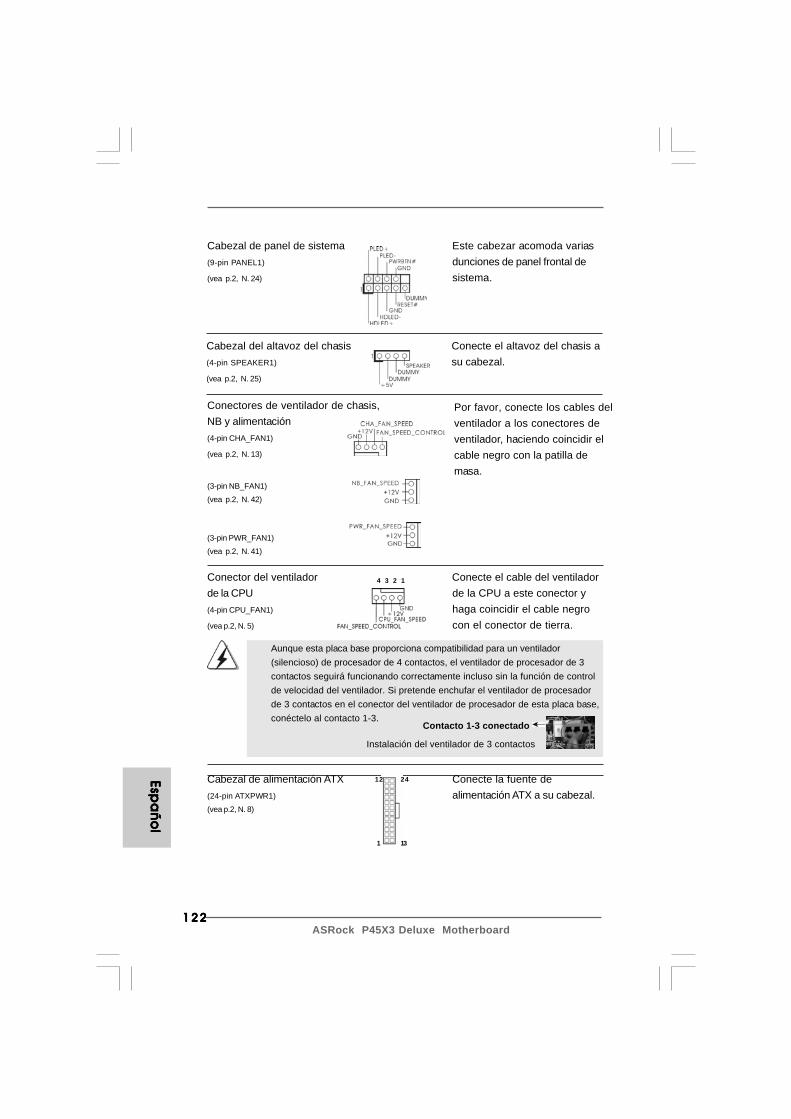
122122122122122ASRock P45X3 Deluxe Motherboard
Cabezal de panel de sistema Este cabezar acomoda varias(9-pin PANEL1) dunciones de panel frontal de(vea p.2, N. 24) sistema.
Conector del ventilador Conecte el cable del ventiladorde la CPU de la CPU a este conector y(4-pin CPU_FAN1) haga coincidir el cable negro(vea p.2, N. 5) con el conector de tierra.
Cabezal del altavoz del chasis Conecte el altavoz del chasis a(4-pin SPEAKER1) su cabezal.(vea p.2, N. 25)
Conectores de ventilador de chasis,NB y alimentación(4-pin CHA_FAN1)
(vea p.2, N. 13)
(3-pin NB_FAN1)
(vea p.2, N. 42)
(3-pin PWR_FAN1)
(vea p.2, N. 41)
Por favor, conecte los cables delventilador a los conectores deventilador, haciendo coincidir elcable negro con la patilla demasa.
4 3 2 1
Aunque esta placa base proporciona compatibilidad para un ventilador(silencioso) de procesador de 4 contactos, el ventilador de procesador de 3contactos seguirá funcionando correctamente incluso sin la función de controlde velocidad del ventilador. Si pretende enchufar el ventilador de procesadorde 3 contactos en el conector del ventilador de procesador de esta placa base,conéctelo al contacto 1-3.
Contacto 1-3 conectado
Instalación del ventilador de 3 contactos
Espa
ño
lEsp
añ
ol
Espa
ño
lEsp
añ
ol
Espa
ño
l
Cabezal de alimentación ATX Conecte la fuente de(24-pin ATXPWR1) alimentación ATX a su cabezal.(vea p.2, N. 8)
12
1
24
13
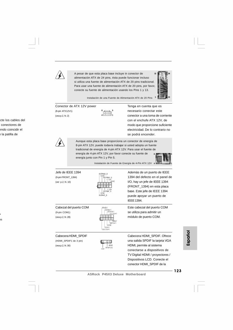
123123123123123ASRock P45X3 Deluxe Motherboard
Cabezal del puerto COM Este cabezal del puerto COM(9-pin COM1) se utiliza para admitir un(vea p.2, N. 28) módulo de puerto COM.
Aunque esta placa base proporciona un conector de energía de8-pin ATX 12V, puede todavía trabajar si usted adopta un fuentetradicional de energía de 4-pin ATX 12V. Para usar el fuente deenergía de 4-pin ATX 12V, por favor conecte su fuente deenergía junto con Pin 1 y Pin 5.
Instalación de Fuente de Energía de 4-Pin ATX 12V
Instalación de una Fuente de Alimentación ATX de 20 Pins
A pesar de que esta placa base incluye in conector dealimentación ATX de 24 pins, ésta puede funcionar inclusosi utiliza una fuente de alimentación ATX de 20 pins tradicional.Para usar una fuente de alimentación ATX de 20 pins, por favor,conecte su fuente de alimentación usando los Pins 1 y 13.
12
1
24
13
ecte los cables del conectores deendo coincidir eln la patilla de
o
os
Esp
añ
ol
Esp
añ
ol
Esp
añ
ol
Esp
añ
ol
Esp
añ
ol
Conector de ATX 12V power Tenga en cuenta que es(8-pin ATX12V1) necesario conectar este(vea p.2, N. 2) conector a una toma de corriente
con el enchufe ATX 12V, demodo que proporcione suficienteelectricidad. De lo contrario nose podrá encender.
8 5
4 1
8 5
4 1
Jefe de IEEE 1394 Además de un puerto de IEEE(9-pin FRONT_1394) 1394 del defecto en el panel de(ver p.2, N. 10) I/O, hay un jefe de IEEE 1394
(FRONT_1394) en esta placabase. Este jefe de IEEE 1394puede apoyar un puerto deIEEE 1394.
Cabecera HDMI_SPDIF Cabecera HDMI_SPDIF. Ofrece(HDMI_SPDIF1 de 3 pin) una salida SPDIF la tarjeta VGA(vea p.2, N. 30) HDMI, permite al sistema
conectarse a dispositivos deTV Digital HDMI / proyectores /Dispositivos LCD. Conecte elconector HDMI_SPDIF de la
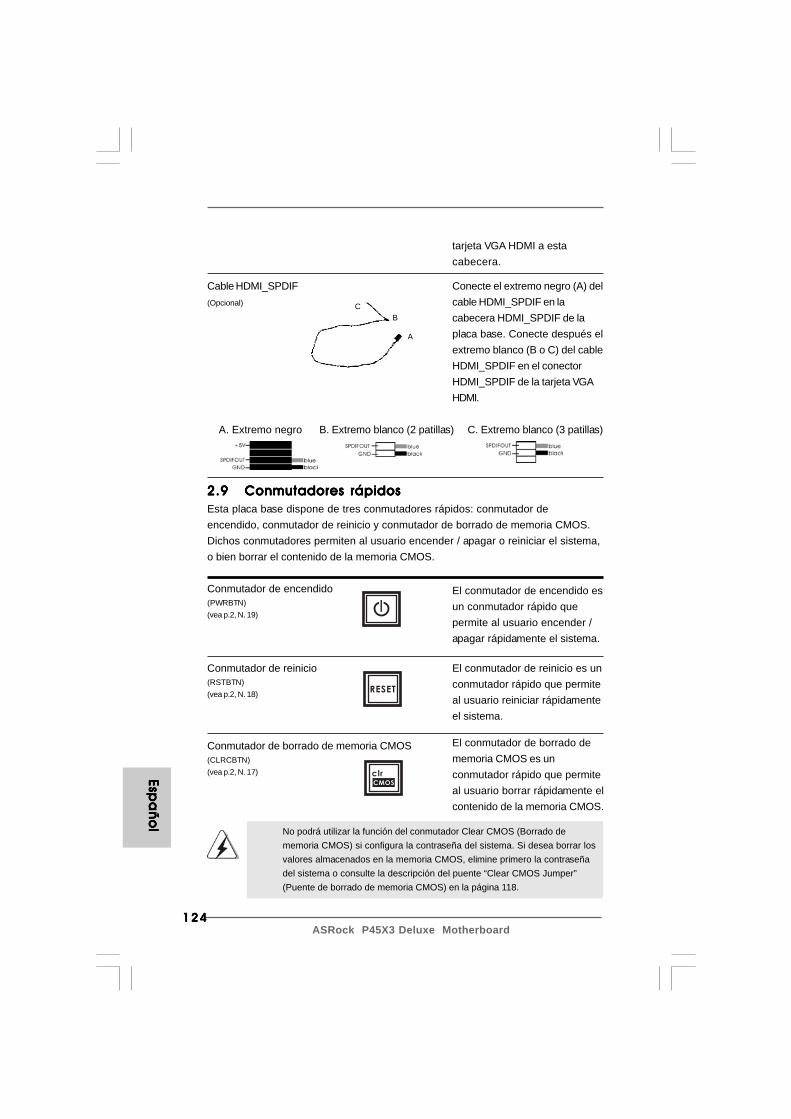
124124124124124ASRock P45X3 Deluxe Motherboard
Espa
ño
lEsp
añ
ol
Espa
ño
lEsp
añ
ol
Espa
ño
l
CB
A
Cable HDMI_SPDIF Conecte el extremo negro (A) del(Opcional) cable HDMI_SPDIF en la
cabecera HDMI_SPDIF de laplaca base. Conecte después elextremo blanco (B o C) del cableHDMI_SPDIF en el conectorHDMI_SPDIF de la tarjeta VGAHDMI.
A. Extremo negro B. Extremo blanco (2 patillas) C. Extremo blanco (3 patillas)
tarjeta VGA HDMI a estacabecera.
2.92.92.92.92.9 Conmutadores rápidosConmutadores rápidosConmutadores rápidosConmutadores rápidosConmutadores rápidosEsta placa base dispone de tres conmutadores rápidos: conmutador deencendido, conmutador de reinicio y conmutador de borrado de memoria CMOS.Dichos conmutadores permiten al usuario encender / apagar o reiniciar el sistema,o bien borrar el contenido de la memoria CMOS.
Conmutador de encendido(PWRBTN)(vea p.2, N. 19)
Conmutador de reinicio(RSTBTN)(vea p.2, N. 18)
El conmutador de encendido esun conmutador rápido quepermite al usuario encender /apagar rápidamente el sistema.
El conmutador de borrado dememoria CMOS es unconmutador rápido que permiteal usuario borrar rápidamente elcontenido de la memoria CMOS.
Conmutador de borrado de memoria CMOS(CLRCBTN)(vea p.2, N. 17)
El conmutador de reinicio es unconmutador rápido que permiteal usuario reiniciar rápidamenteel sistema.
RESET
clr
CMOS
No podrá utilizar la función del conmutador Clear CMOS (Borrado dememoria CMOS) si configura la contraseña del sistema. Si desea borrar losvalores almacenados en la memoria CMOS, elimine primero la contraseñadel sistema o consulte la descripción del puente “Clear CMOS Jumper”(Puente de borrado de memoria CMOS) en la página 118.

125125125125125ASRock P45X3 Deluxe Motherboard
2.112.112.112.112.11 Guía de instalación del controladorGuía de instalación del controladorGuía de instalación del controladorGuía de instalación del controladorGuía de instalación del controladorPara instalar los controladores en el sistema, inserte en primer lugar el CD desoporte en la unidad óptica. A continuación, se detectarán automáticamente loscontroladores compatibles con el sistema y se mostrarán en la página decontroladores de CD compatibles. Siga el orden de arriba a abajo para instalar loscontroladores requeridos. Los controladores que instale pueden funcionarcorrectamente.
Uso de dispositivos SATA / SATAII sin funciones NCQ
PASO 1: Configuración de la BIOS.A. Entre en BIOS SETUP UTILITY Òpantalla Avanzada ÒIDE Configuración.B. Configure la “SATAII Configuration” (“Configuración SATAII”) a [Enhanced]
(Optimizada), y luego configure la opción que aparece en “Configure SATAII as”(“Configurar SATAII como”) a [IDE].
PASO 2: Instale Windows® 2000 / XP / XP 64 bits en su sistema.
2.12 Instalación de Windows2.12 Instalación de Windows2.12 Instalación de Windows2.12 Instalación de Windows2.12 Instalación de Windows®®®®® 2000 / XP / XP 64 bits / 2000 / XP / XP 64 bits / 2000 / XP / XP 64 bits / 2000 / XP / XP 64 bits / 2000 / XP / XP 64 bits /
Vista Vista Vista Vista VistaTMTMTMTMTM / Vista / Vista / Vista / Vista / VistaTMTMTMTMTM 64 bits sin funciones RAID 64 bits sin funciones RAID 64 bits sin funciones RAID 64 bits sin funciones RAID 64 bits sin funciones RAIDSi desea instalar Windows® 2000 / XP / 64 bits / VistaTM / VistaTM 64 bits en susdiscos duros SATA / SATAII sin funciones RAID, siga los procedimientos que seindican a continuación en función del sistema operativo que tenga instalado.
2.12.1 Instalación de Windows2.12.1 Instalación de Windows2.12.1 Instalación de Windows2.12.1 Instalación de Windows2.12.1 Instalación de Windows®®®®® 2000 / XP / XP 64 bits 2000 / XP / XP 64 bits 2000 / XP / XP 64 bits 2000 / XP / XP 64 bits 2000 / XP / XP 64 bits
sin funciones RAID sin funciones RAID sin funciones RAID sin funciones RAID sin funciones RAIDSi desea instalar Windows® 2000 / XP / 64 bits en sus discos duros SATA / SATAIIsin funciones RAID, por favor siga los pasos siguientes.
Por que el controlador de Windows® 2000 AHCI no es proporcionado por elproveedor de chipset, las funciones de AHCI no son compatibles con Windows®
2000.
Esp
añ
ol
Esp
añ
ol
Esp
añ
ol
Esp
añ
ol
Esp
añ
ol
2.102.102.102.102.10 Indicador LED de depuraciónIndicador LED de depuraciónIndicador LED de depuraciónIndicador LED de depuraciónIndicador LED de depuraciónEl indicador LED de depuración instalado en la placa se utiliza para presentarinformación en forma de códigos que facilitan la resolución de problemas. Consultelos diagramas de las páginas 28, 29 y 30 si desea obtener más información acercade la lectura de los códigos del indicador LED de depuración.
de encendido esrápido querio encender /ente el sistema.
de borrado dees unido que permiter rápidamente elmemoria CMOS.
de reinicio es unido que permiteiar rápidamente
126126126126126ASRock P45X3 Deluxe Motherboard
Espa
ño
lEsp
añ
ol
Espa
ño
lEsp
añ
ol
Espa
ño
l
Uso de dispositivos SATA / SATAII con funciones NCQ
PASO 1: Configuración de la BIOS.A. Entre en BIOS SETUP UTILITY Òpantalla Avanzada ÒIDE Configuración.B. Configure la “SATAII Configuration” (“Configuración SATAII”) a [Enhanced]
(Optimizada), y luego configure la opción que aparece en “Configure SATAII as”(“Configurar SATAII como”) a [AHCI].
PASO 2: Instale Windows® VistaTM / VistaTM 64 bits en su sistema.Inserte el disco óptico de Windows® VistaTM / VistaTM 64 bits en la unidad óptica parainiciar el sistema y siga las instrucciones para instalar el sistema operativo Windows®
VistaTM / VistaTM 64 bits en el equipo. Cuando aparezca la página “Where do you wantto install Windows?” (¿Dónde desea instalar Windows?), inserte el CD de soporte deASRock en la unidad óptica y haga clic en el botón “Load Driver” (Cargar controlador)situado en la parte inferior izquierda para cargar los controladores AHCI de Intel®. Loscontroladores AHCI de Intel® se encuentran en la siguiente ruta de nuestro CD desoporte:.. \ I386 (para usuarios de Windows® VistaTM).. \ AMD64 (para usuarios de Windows® VistaTM 64 bits)A continuación, vuelva a insertar el disco óptico de Windows® VistaTM / VistaTM 64 bitsen la unidad óptica para continuar con la instalación.
PASO 1: Configuración de la BIOS.A. Entre en BIOS SETUP UTILITY Òpantalla Avanzada ÒIDE Configuración.B. Configure la “SATAII Configuration” (“Configuración SATAII”) a [Enhanced]
(Optimizada), y luego configure la opción que aparece en “Configure SATAII as”(“Configurar SATAII como”) a [IDE].
PASO 2: Instale Windows® VistaTM / VistaTM 64 bits en su sistema.
2.12.2 Instalación de Windows2.12.2 Instalación de Windows2.12.2 Instalación de Windows2.12.2 Instalación de Windows2.12.2 Instalación de Windows®®®®® Vista Vista Vista Vista VistaTMTMTMTMTM / Vista / Vista / Vista / Vista / VistaTMTMTMTMTM 64 bits 64 bits 64 bits 64 bits 64 bits
sin funciones RAID sin funciones RAID sin funciones RAID sin funciones RAID sin funciones RAIDSi desea instalar Windows® VistaTM / VistaTM 64 bits en sus discos duros SATA /SATAII sin funciones RAID, por favor siga los pasos siguientes.
Uso de dispositivos SATA / SATAII sin funciones NCQ
127127127127127ASRock P45X3 Deluxe Motherboard
3. BIOS Información3. BIOS Información3. BIOS Información3. BIOS Información3. BIOS InformaciónEl Flash Memory de la placa madre deposita SETUP Utility. Durante el Power-Up(POST) apriete <F2> para entrar en la BIOS. Sí usted no oprime ninguna tecla, elPOST continúa con sus rutinas de prueba. Si usted desea entrar en la BIOS despuésdel POST, por favor reinicie el sistema apretando <Ctl> + <Alt> + <Borrar>, o apretandoel botón Reset en el panel del ordenador. Para información detallada sobre comoconfigurar la BIOS, por favor refiérase al Manual del Usuario (archivo PDF) contenidoen el CD.
4.Información de Sof4.Información de Sof4.Información de Sof4.Información de Sof4.Información de Software Supportware Supportware Supportware Supportware Support CDt CDt CDt CDt CDEsta placa-base soporta diversos tipos de sistema operativo Windows®: 2000 / XP /XP 64 bits / VistaTM / VistaTM 64 bits. El CD de instalación que acompaña la placa-basetrae todos los drivers y programas utilitarios para instalar y configurar la placa-base.Para iniciar la instalación, ponga el CD en el lector de CD y se desplegará el MenúPrincipal automáticamente si «AUTORUN» está habilitado en su computadora.Si el Menú Principal no aparece automáticamente, localice y doble-pulse en el archivo“ASSETUP.EXE” para iniciar la instalación.
2.132.132.132.132.13 TTTTTecnología de Fecnología de Fecnología de Fecnología de Fecnología de Forororororzado de Rzado de Rzado de Rzado de Rzado de Reloj (Overclocking) noeloj (Overclocking) noeloj (Overclocking) noeloj (Overclocking) noeloj (Overclocking) no
relacionadorelacionadorelacionadorelacionadorelacionadoEsta tarjeta madre soporta Tecnología de Forzado de Reloj (Overclocking) norelacionado, lo cual significa que durante el forzado de reloj, FSB disfruta unmayor margen debido a los buses fijos PCI / PCIE. Antes de que active la funciónde Forzado de Reloj (Overclocking) no relacionado, por favor entre a la opción de“Modo de Forzado de Reloj” de la configuración de BIOS para establecer laselección de [Auto] a [Manual]. Por lo tanto, FSB de CPU no está relacionado duranteel forzado de reloj, sino los buses PCI / PCIE están en el modo fijo de manera queFSB puede operar bajo un ambiente de forzado de reloj más estable.
Consulte la advertencia de la página 107 para obtenerinformación sobre el posible riesgo que se asume al aumentar lavelocidad del reloj antes de aplicar la tecnología de aumento develocidad liberada.
Esp
añ
ol
Esp
añ
ol
Esp
añ
ol
Esp
añ
ol
Esp
añ
ol

151151151151151ASRock P45X3 Deluxe Motherboard
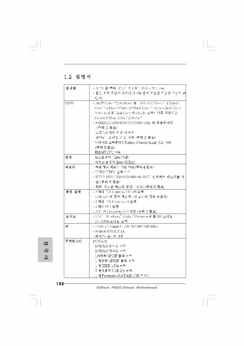
152152152152152ASRock P45X3 Deluxe Motherboard
®
®
® ®
®
®
®
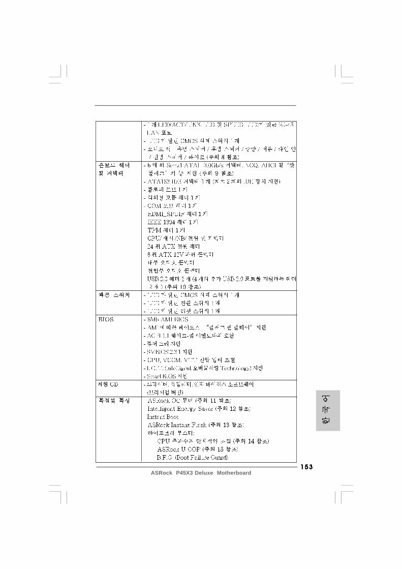
153153153153153ASRock P45X3 Deluxe Motherboard
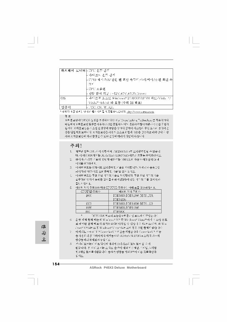
154154154154154ASRock P45X3 Deluxe Motherboard
“ ”
® ®
® ®
®
155155155155155ASRock P45X3 Deluxe Motherboard
“ ” “”
®
®
® ®
“ ”

156156156156156ASRock P45X3 Deluxe Motherboard
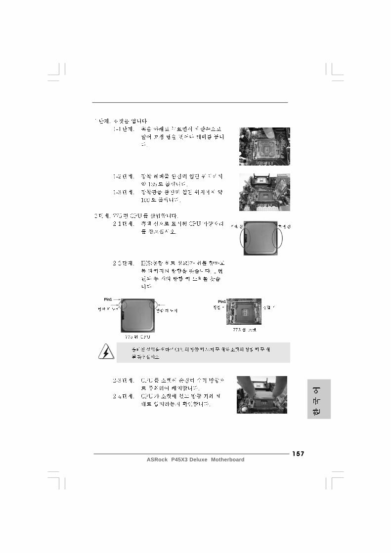
157157157157157ASRock P45X3 Deluxe Motherboard
Pin1Pin1
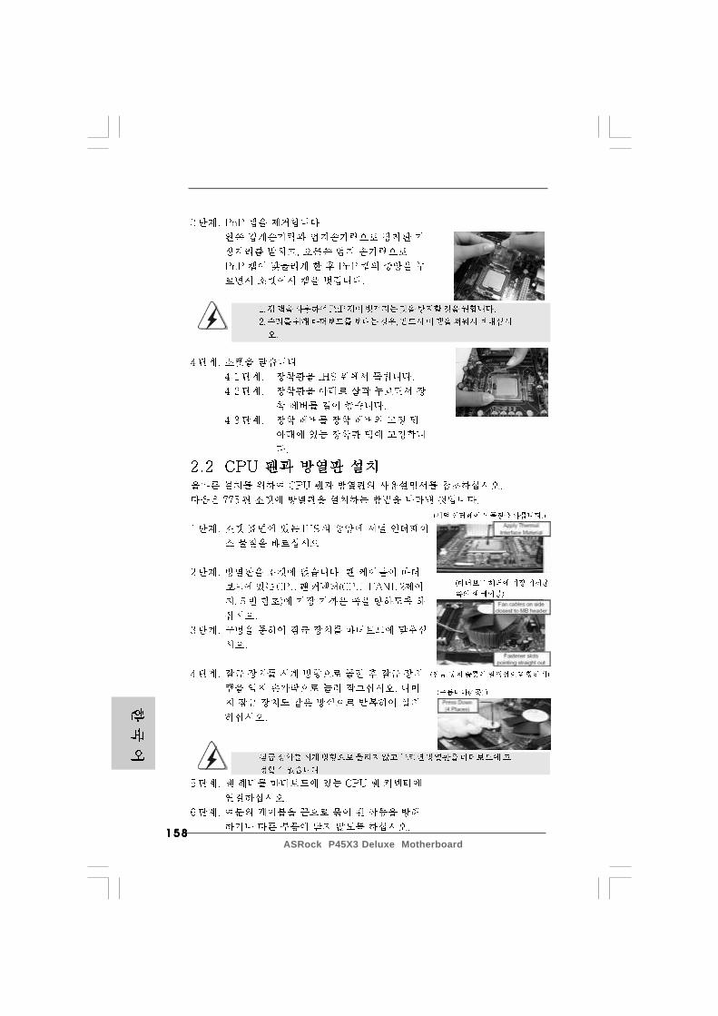
158158158158158ASRock P45X3 Deluxe Motherboard
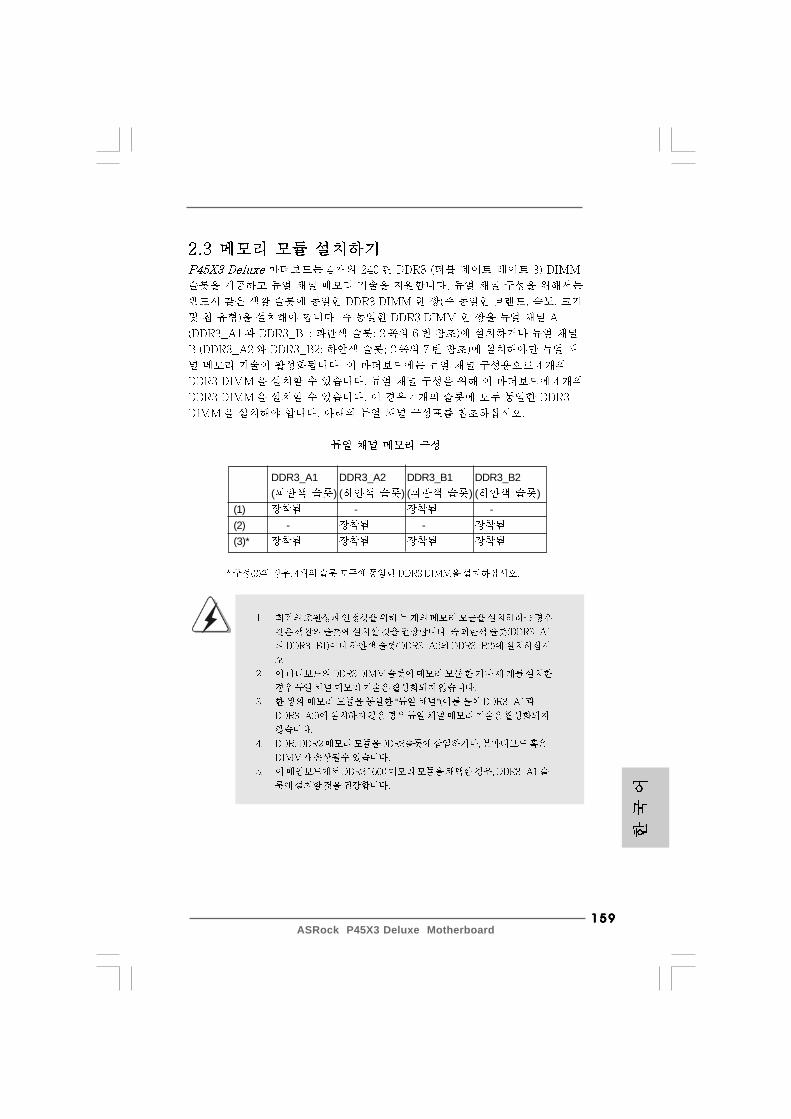
159159159159159ASRock P45X3 Deluxe Motherboard
DDR3_A1 DDR3_A2 DDR3_B1 DDR3_B2( ) ( ) ( ) ( )
(1) - -(2) - -(3)*
“ ”
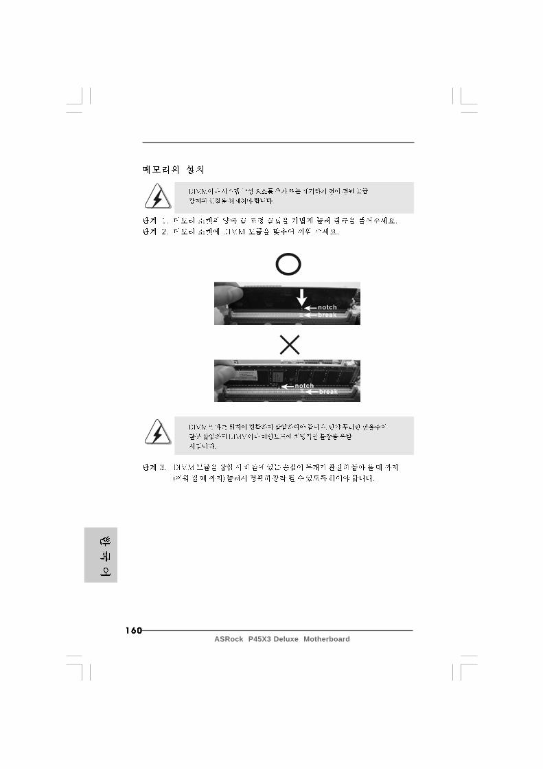
160160160160160ASRock P45X3 Deluxe Motherboard
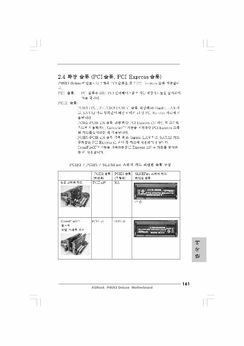
161161161161161ASRock P45X3 Deluxe Motherboard
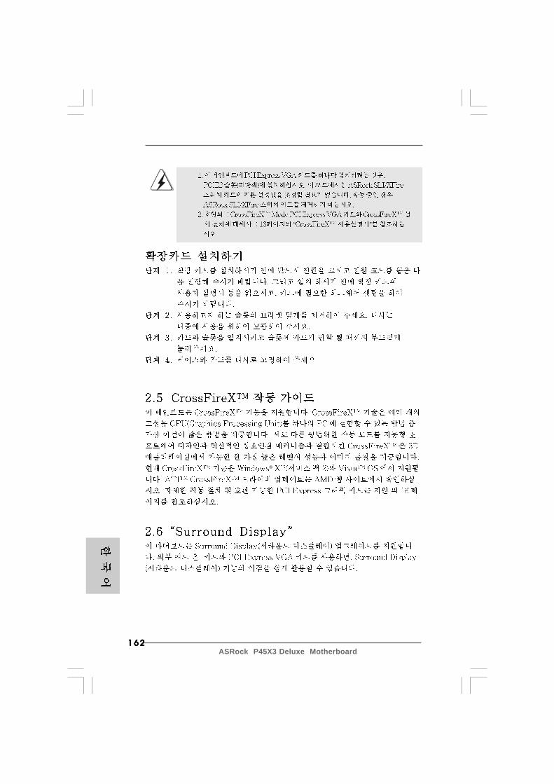
162162162162162ASRock P45X3 Deluxe Motherboard
®
“ ”

163163163163163ASRock P45X3 Deluxe Motherboard
“ ”“ ”
“ ”
“ ”
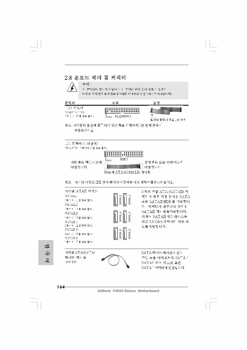
164164164164164ASRock P45X3 Deluxe Motherboard
SATA
II_6
SATA
II_4
SATA
II_2
SATA
II_5
SATA
II_3
SATA
II_1
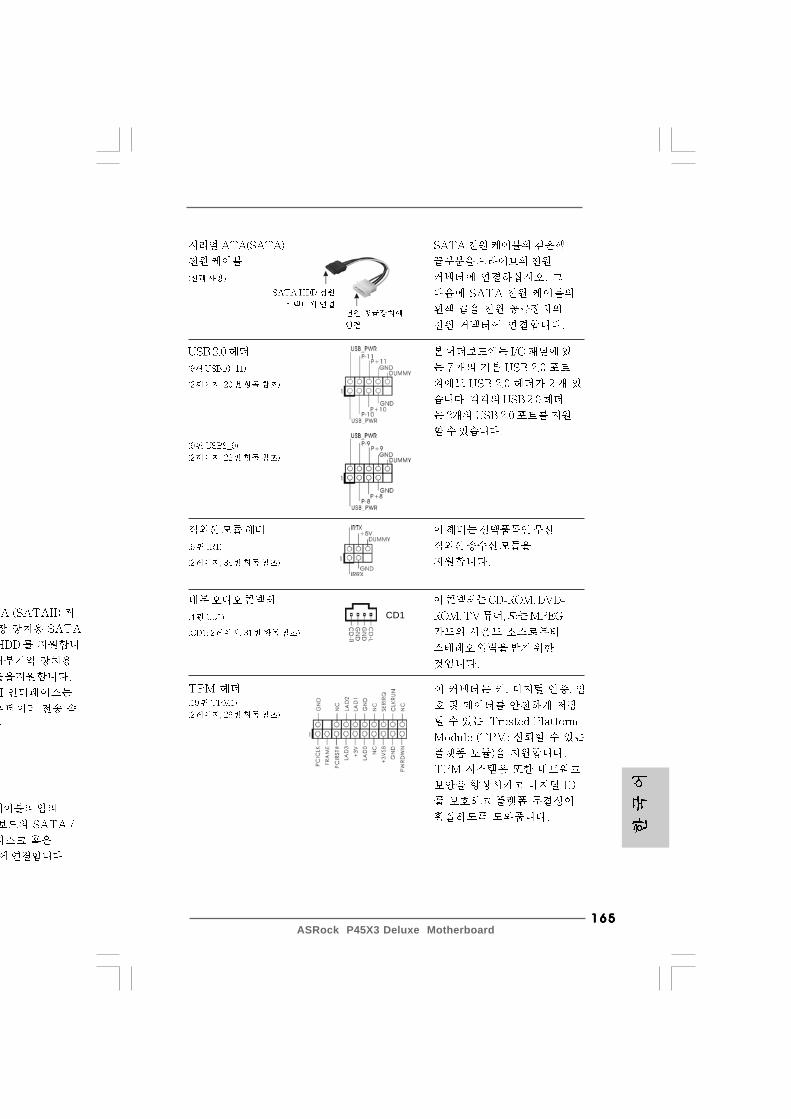
165165165165165ASRock P45X3 Deluxe Motherboard
CD1

166166166166166ASRock P45X3 Deluxe Motherboard
®
®
®
®
“ ”“ ”
“ ” “ ” ®
“ ” “”

167167167167167ASRock P45X3 Deluxe Motherboard
4 3 2 1
12
1
24
13
12
1
24
13
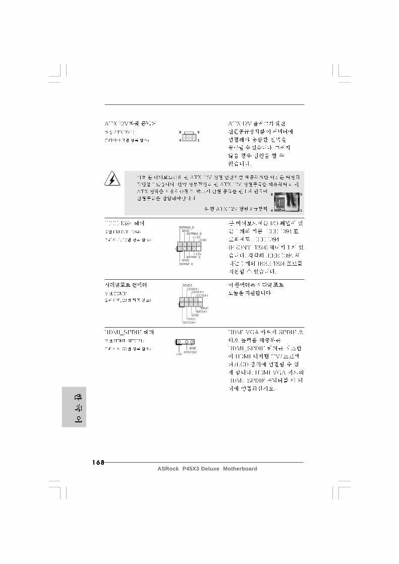
168168168168168ASRock P45X3 Deluxe Motherboard
8 5
4 1
8 5
4 1
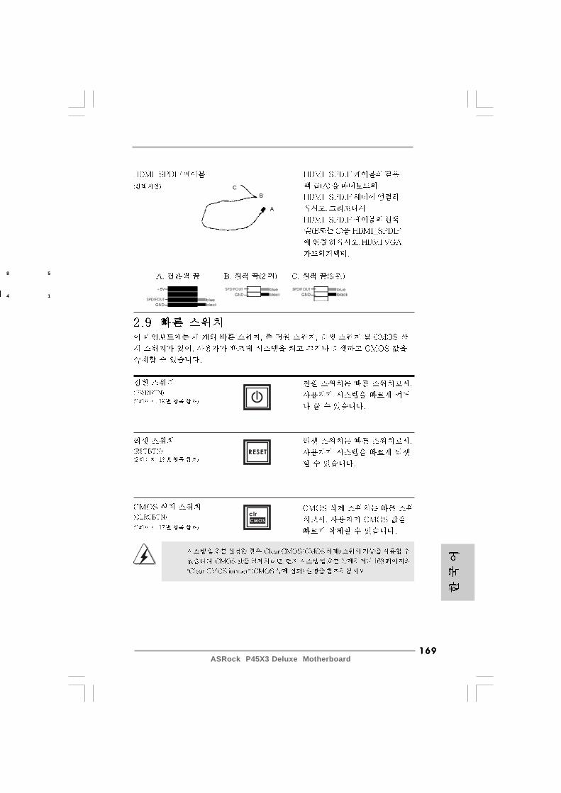
169169169169169ASRock P45X3 Deluxe Motherboard
CB
A
8 5
4 1
RESET
clr
CMOS
“ ”
170170170170170ASRock P45X3 Deluxe Motherboard
®
®
®
®
®
®
®

171171171171171ASRock P45X3 Deluxe Motherboard
®
®
®
®
® ®
\ ®
\ ®
®
®
®
172172172172172ASRock P45X3 Deluxe Motherboard
“ ”
“ ”
\ \
“ ”
173173173173173ASRock P45X3 Deluxe Motherboard
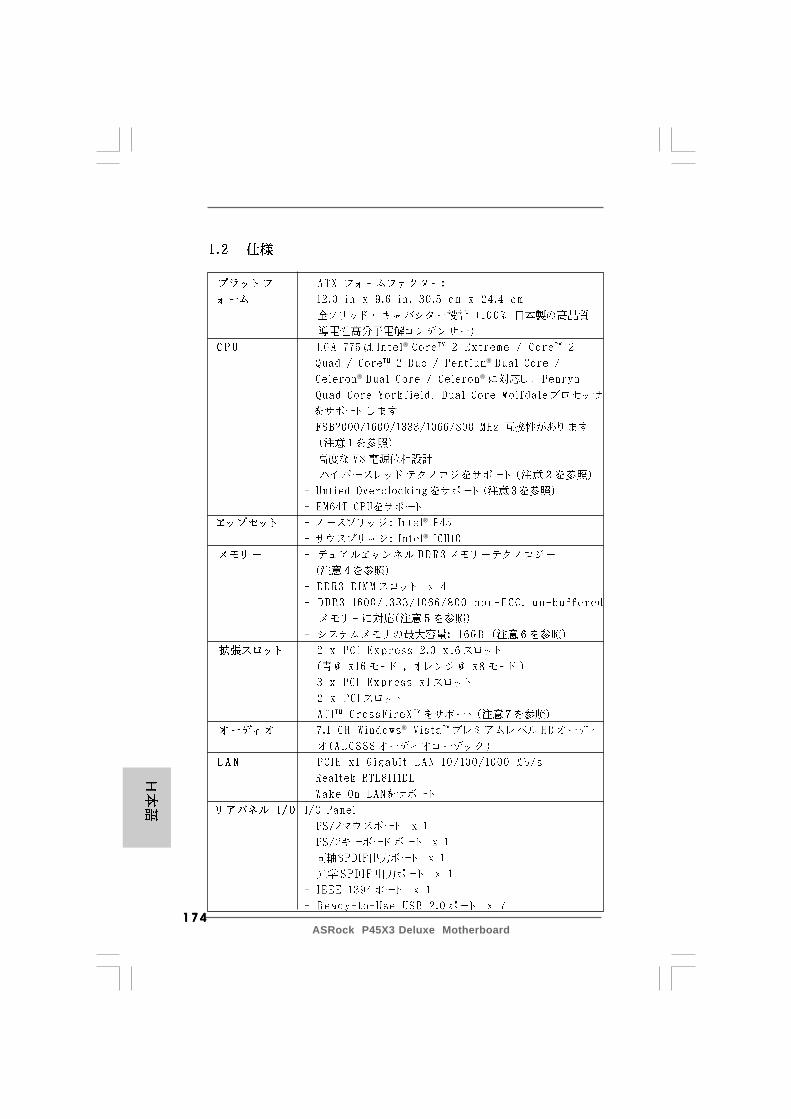
174174174174174ASRock P45X3 Deluxe Motherboard
®
®
® ®
®
®
®

175175175175175ASRock P45X3 Deluxe Motherboard
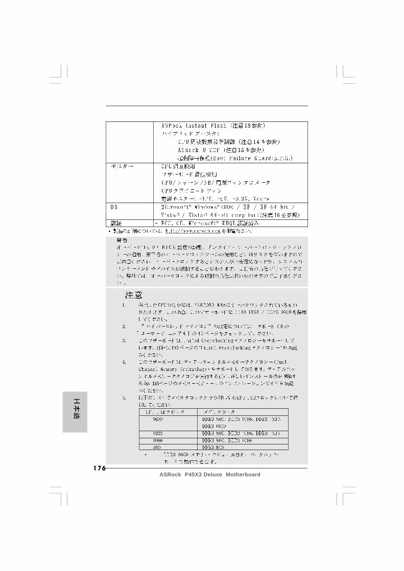
176176176176176ASRock P45X3 Deluxe Motherboard
“ ”
® ®
®
177177177177177ASRock P45X3 Deluxe Motherboard
® ®
®
®
® ® TM
TM
®
®
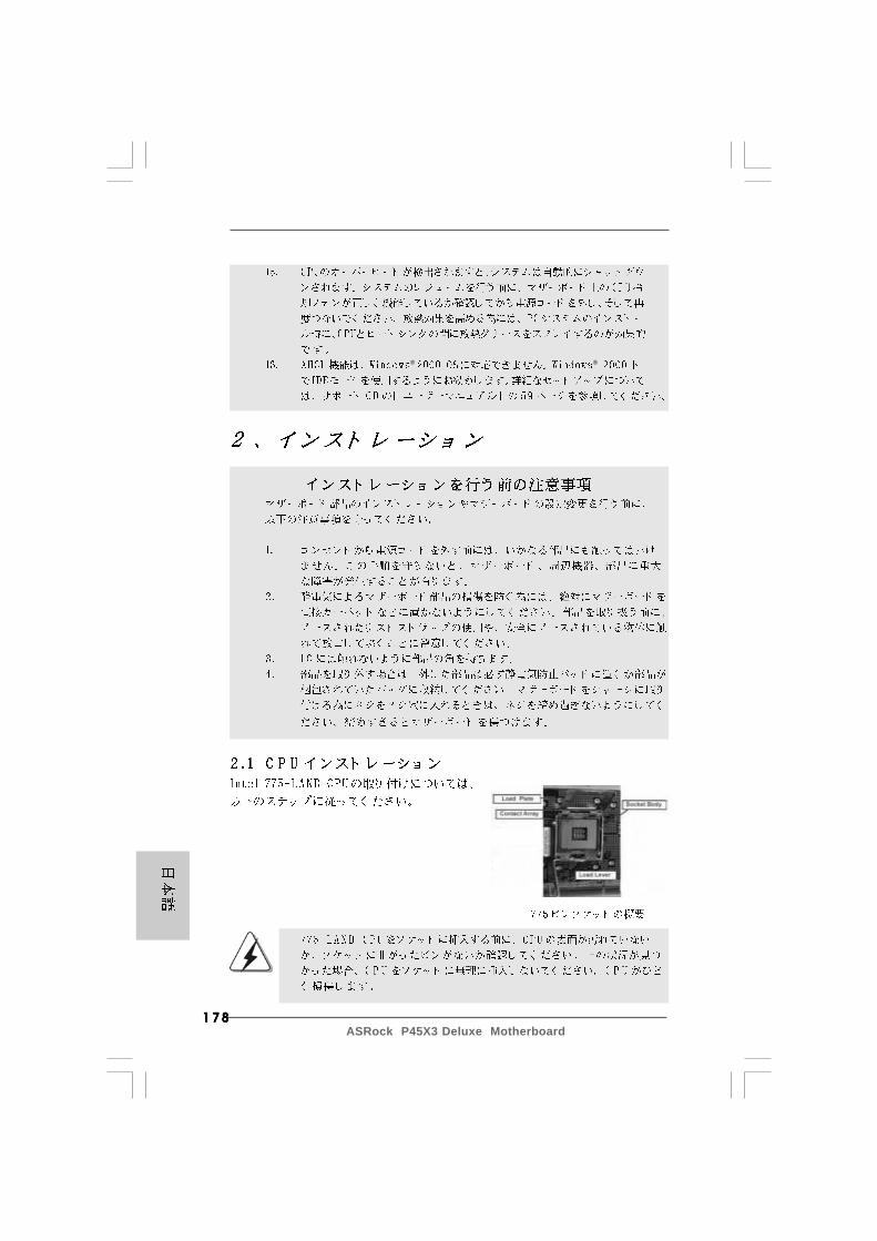
178178178178178ASRock P45X3 Deluxe Motherboard
® ®
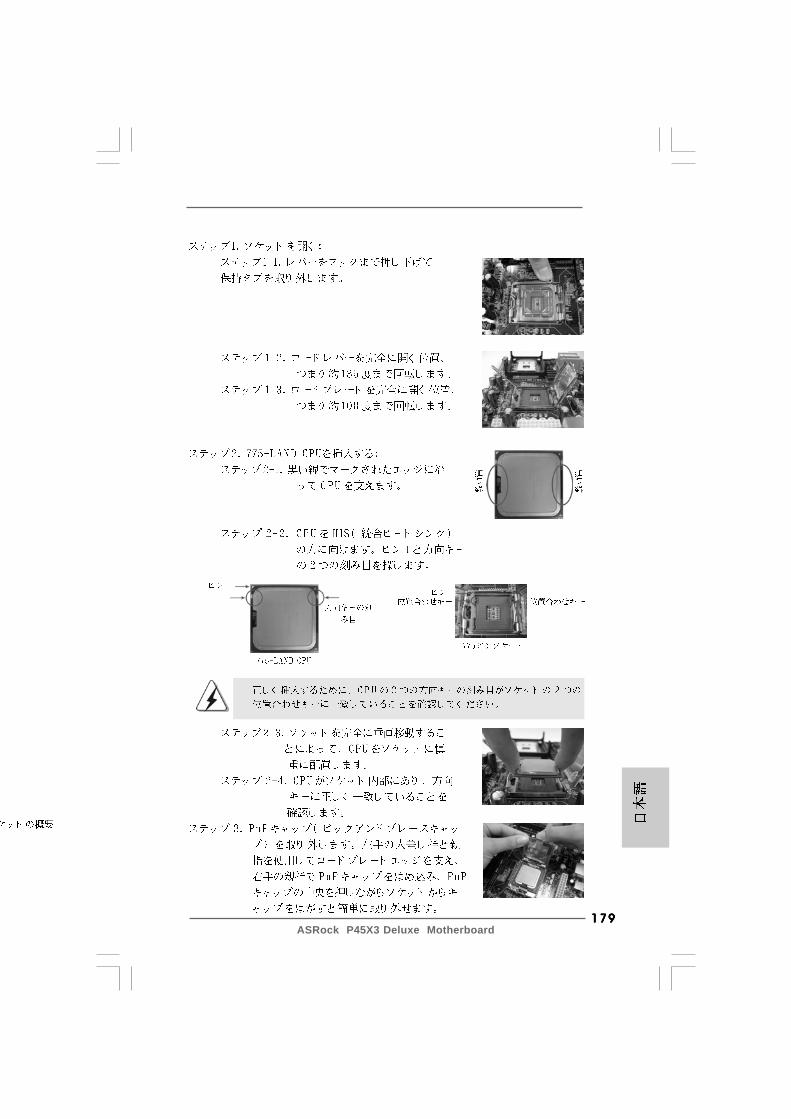
179179179179179ASRock P45X3 Deluxe Motherboard
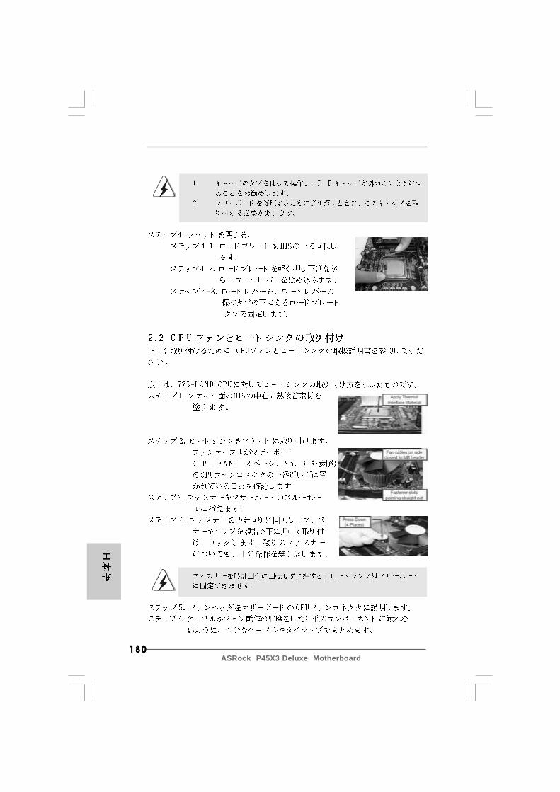
180180180180180ASRock P45X3 Deluxe Motherboard
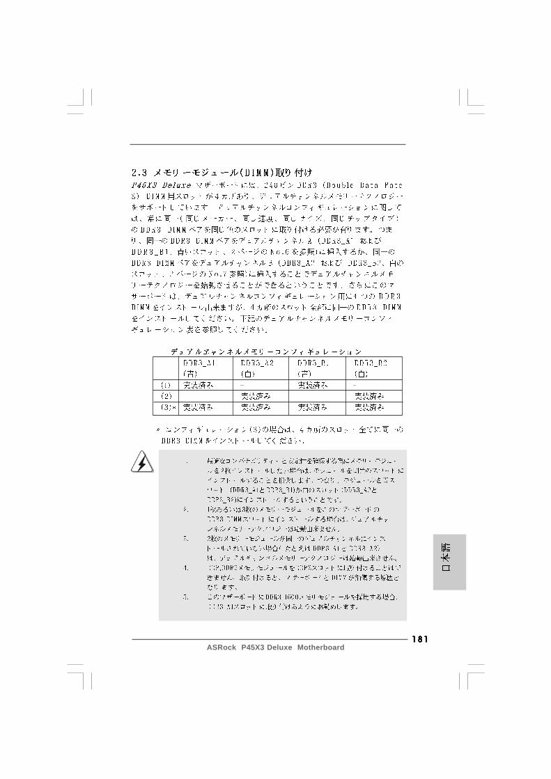
181181181181181ASRock P45X3 Deluxe Motherboard

182182182182182ASRock P45X3 Deluxe Motherboard
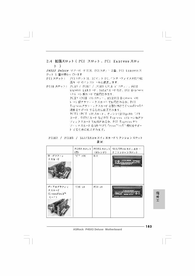
183183183183183ASRock P45X3 Deluxe Motherboard
184184184184184ASRock P45X3 Deluxe Motherboard
®
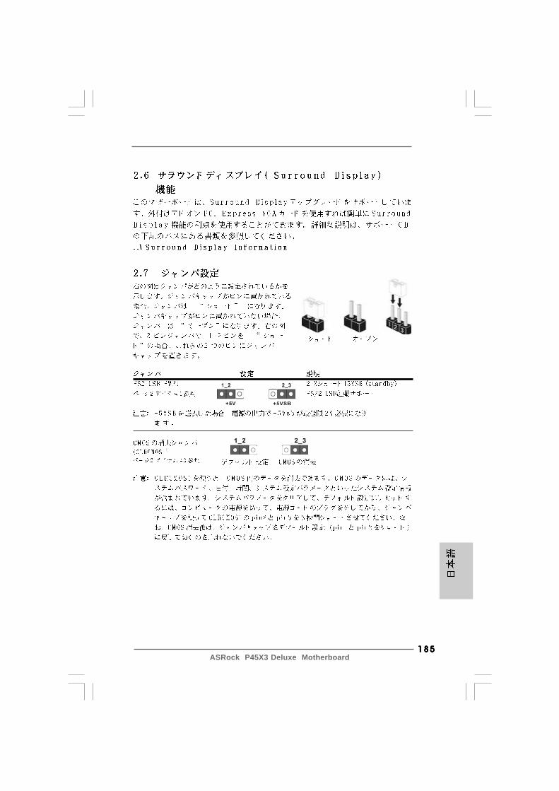
185185185185185ASRock P45X3 Deluxe Motherboard
\
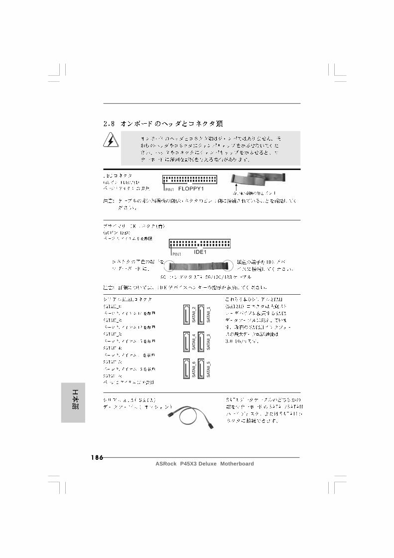
186186186186186ASRock P45X3 Deluxe Motherboard
SATA
II_6
SATA
II_4
SATA
II_2
SATA
II_5
SATA
II_3
SATA
II_1

187187187187187ASRock P45X3 Deluxe Motherboard
CD1
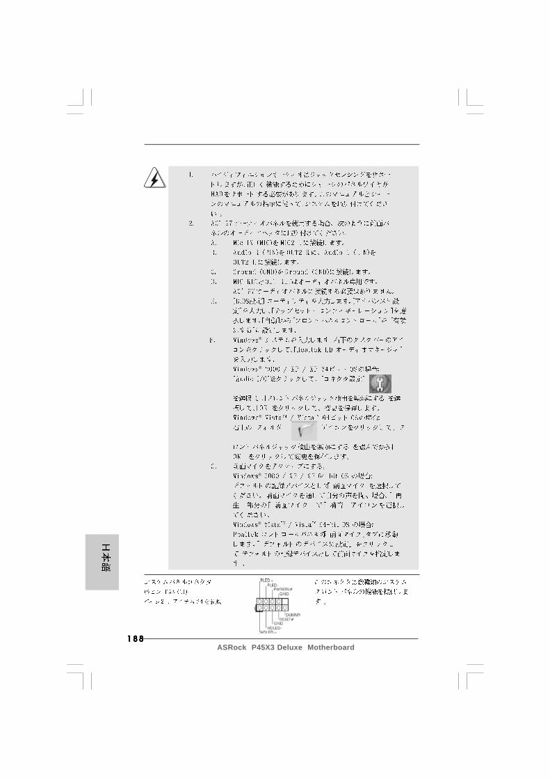
188188188188188ASRock P45X3 Deluxe Motherboard
®
®
®
®
®
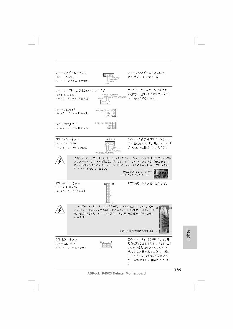
189189189189189ASRock P45X3 Deluxe Motherboard
4 3 2 1
12
1
24
13
12
1
24
13
8 5
4 1

190190190190190ASRock P45X3 Deluxe Motherboard
CB
A
8 5
4 1
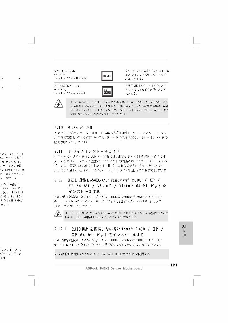
191191191191191ASRock P45X3 Deluxe Motherboard
®
®
®
®
®
®
8 5
4 1
RESET
clr
CMOS
192192192192192ASRock P45X3 Deluxe Motherboard
®
®
®
®
®
®
®
®
\ ®
\ ®
®
®
193193193193193ASRock P45X3 Deluxe Motherboard
® ® TM
TM

194194194194194ASRock P45X3 Deluxe Motherboard

195195195195195ASRock P45X3 Deluxe Motherboard
®
®
® ®
® ®
®

196196196196196ASRock P45X3 Deluxe Motherboard
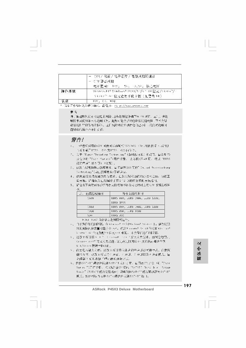
197197197197197ASRock P45X3 Deluxe Motherboard
® ®
® ®
® ®
198198198198198ASRock P45X3 Deluxe Motherboard
®
®
®
® ®
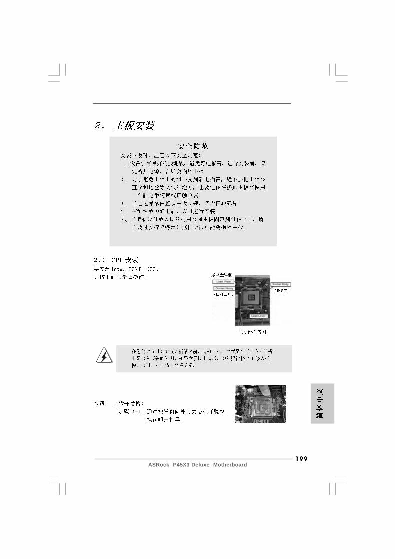
199199199199199ASRock P45X3 Deluxe Motherboard
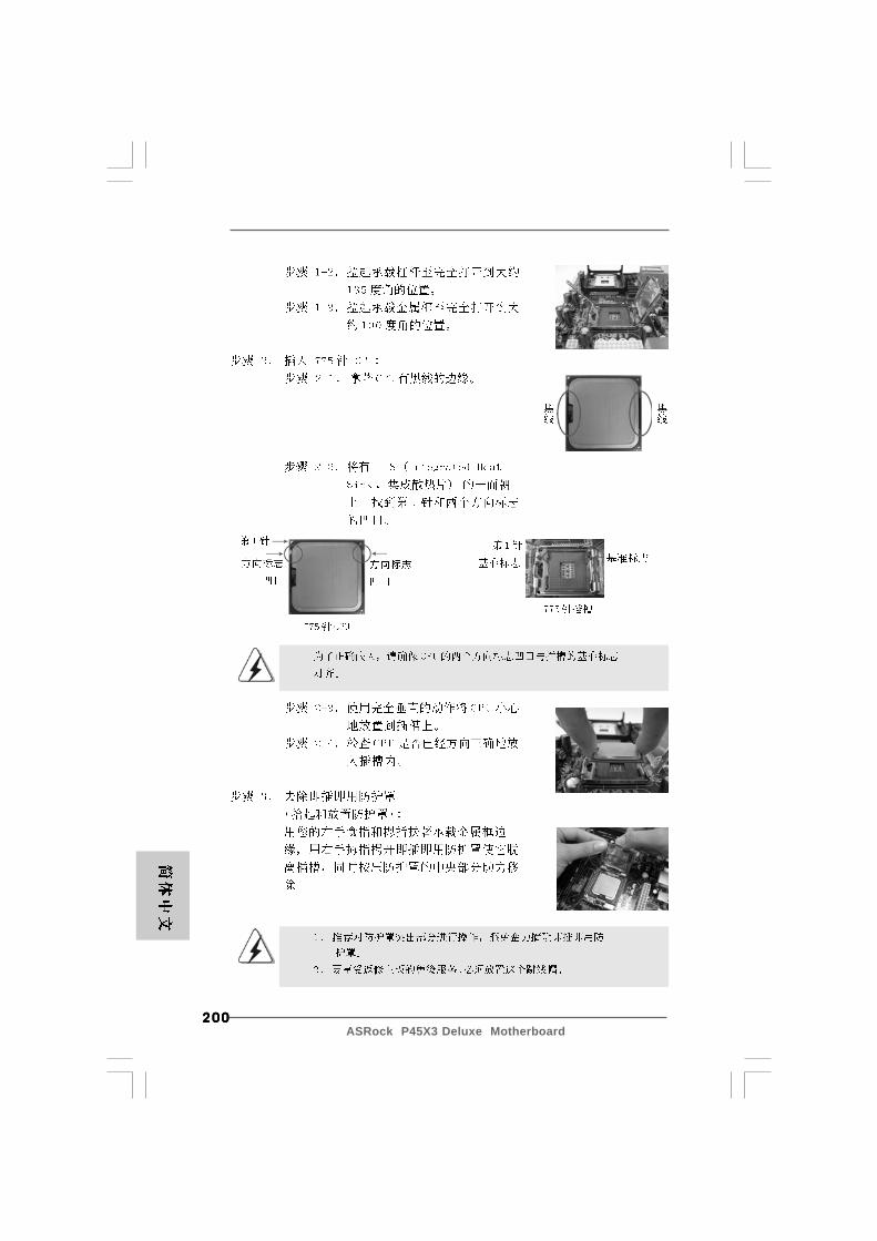
200200200200200ASRock P45X3 Deluxe Motherboard
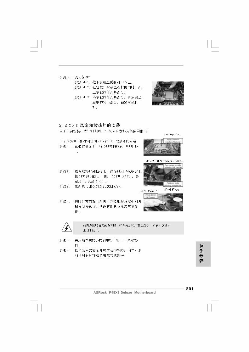
201201201201201ASRock P45X3 Deluxe Motherboard
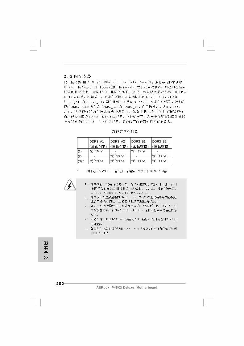
202202202202202ASRock P45X3 Deluxe Motherboard
DDR3_A1 DDR3_A2 DDR3_B1 DDR3_B2( ) ( ) ( ) ( )
(1) - -(2) - -(3) *
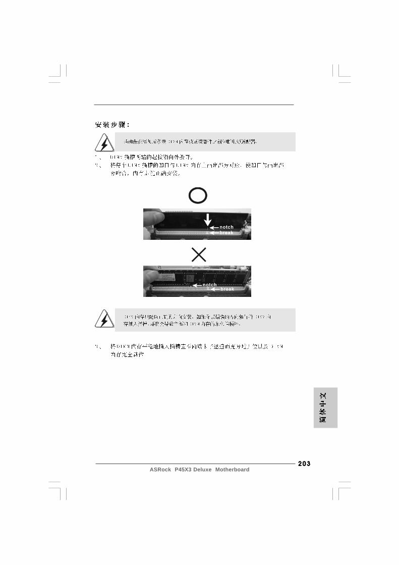
203203203203203ASRock P45X3 Deluxe Motherboard
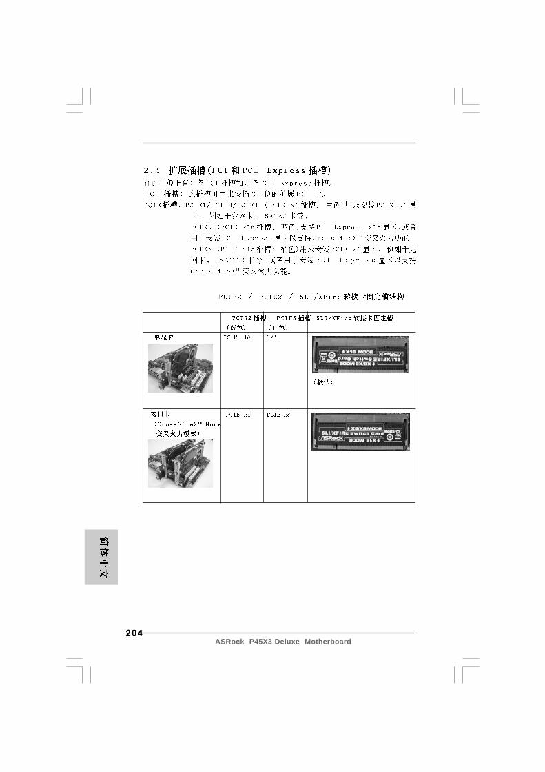
204204204204204ASRock P45X3 Deluxe Motherboard
205205205205205ASRock P45X3 Deluxe Motherboard
® ®

206206206206206ASRock P45X3 Deluxe Motherboard
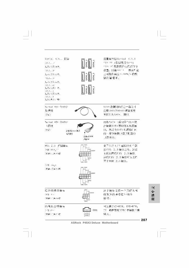
207207207207207ASRock P45X3 Deluxe Motherboard
SATA
II_6
SATA
II_4
SATA
II_2
SATA
II_5
SATA
II_3
SATA
II_1
CD1

208208208208208ASRock P45X3 Deluxe Motherboard
®
®
®
®
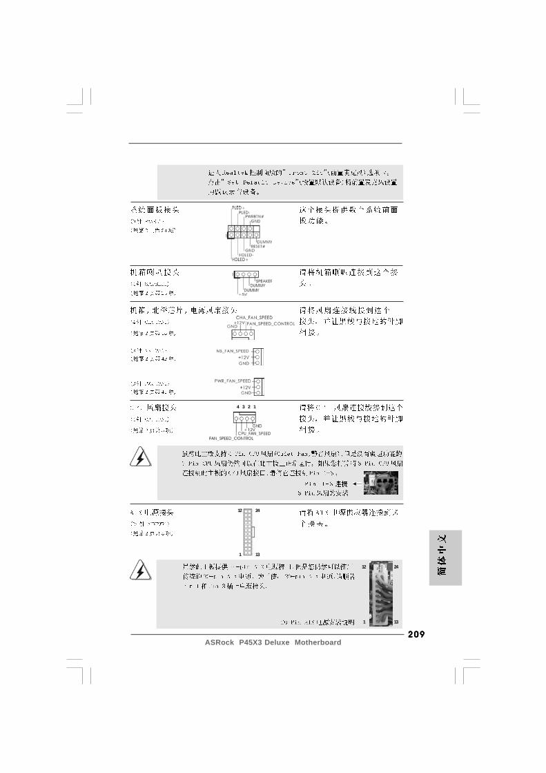
209209209209209ASRock P45X3 Deluxe Motherboard
12
1
24
13
12
1
24
13
4 3 2 1
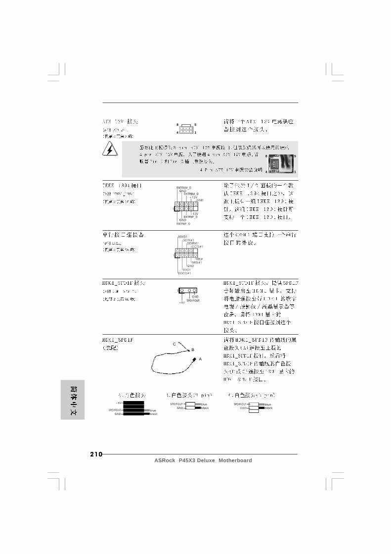
210210210210210ASRock P45X3 Deluxe Motherboard
CB
A
8 5
4 1
8 5
4 1
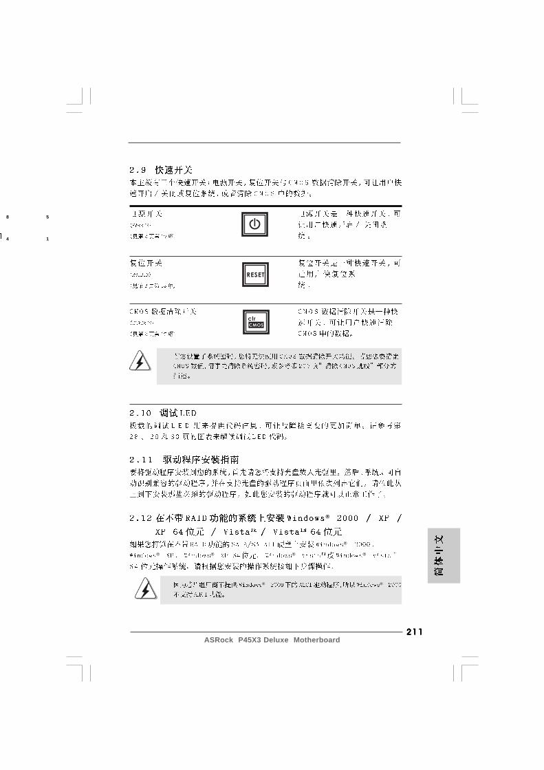
211211211211211ASRock P45X3 Deluxe Motherboard
®
® ® ® ® ®
® ®
8 5
4 1
RESET
clr
CMOS
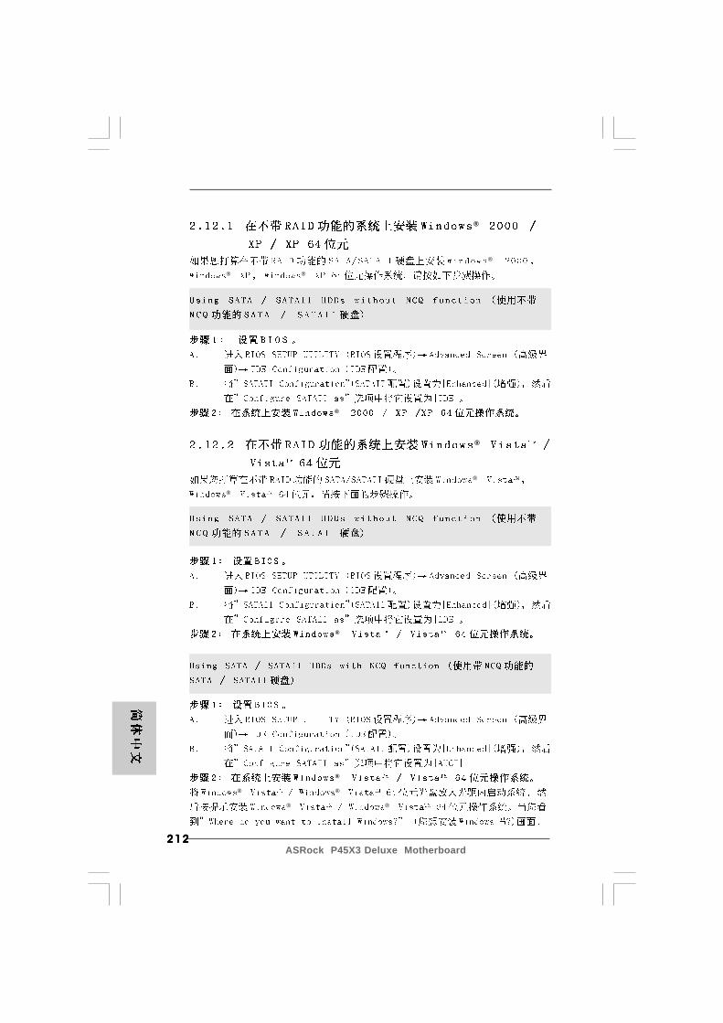
212212212212212ASRock P45X3 Deluxe Motherboard
® ® ®
® ®
®
®
®
® ®
®
® ® ®
213213213213213ASRock P45X3 Deluxe Motherboard
® ®
® ®
® ®
® ®
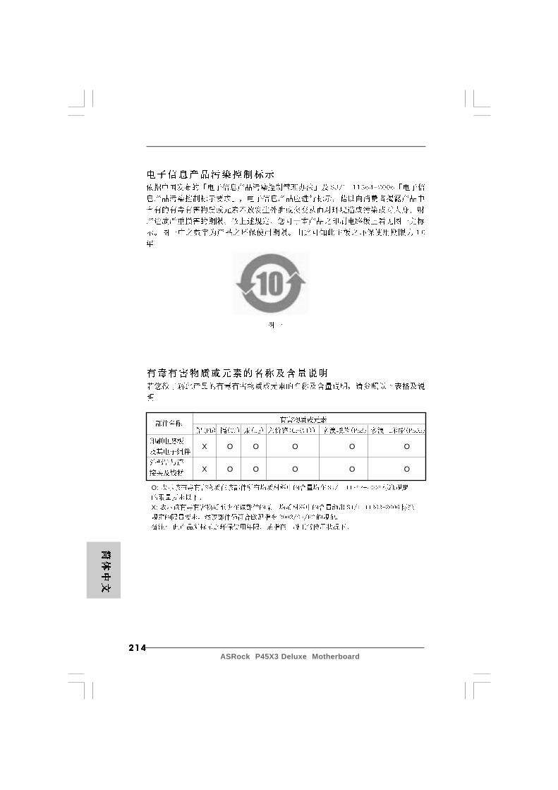
214214214214214ASRock P45X3 Deluxe Motherboard
X O O O O O
X O O O O O
O:
X:
215215215215215ASRock P45X3 Deluxe Motherboard
O
O
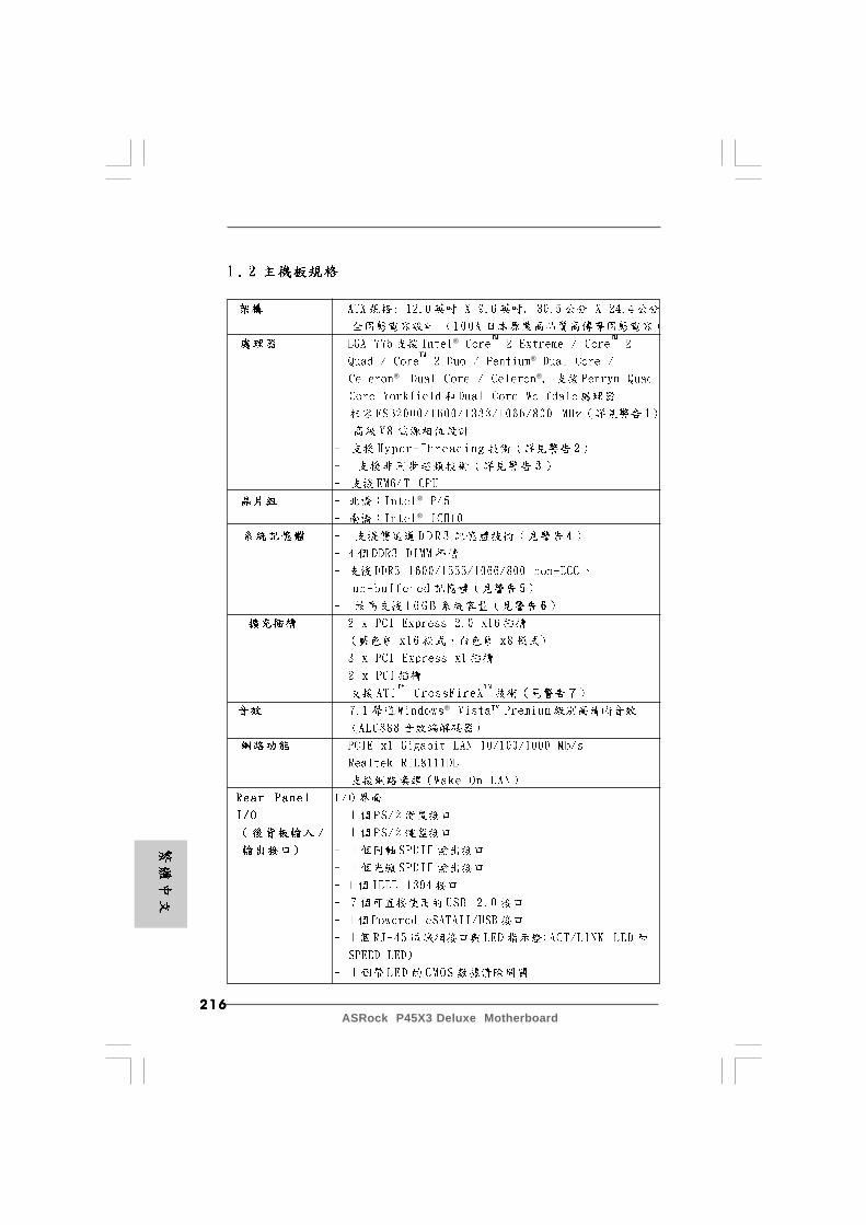
216216216216216ASRock P45X3 Deluxe Motherboard
®
®
® ®
®
®
®
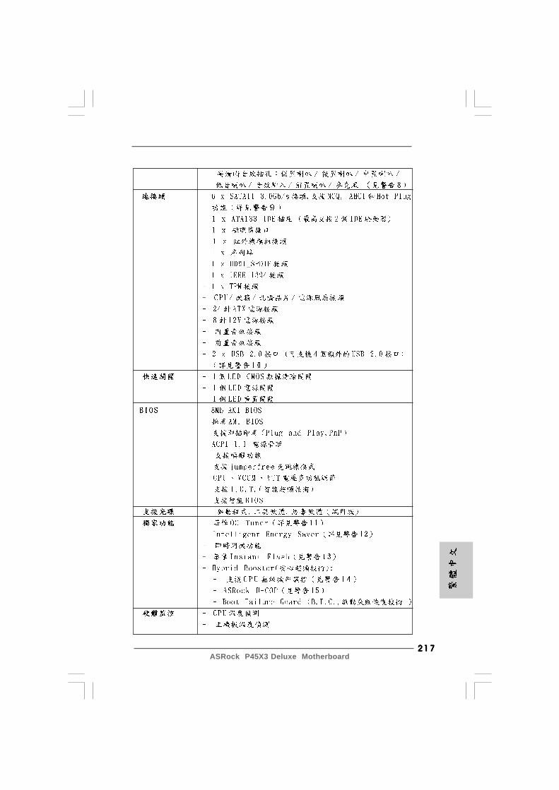
217217217217217ASRock P45X3 Deluxe Motherboard
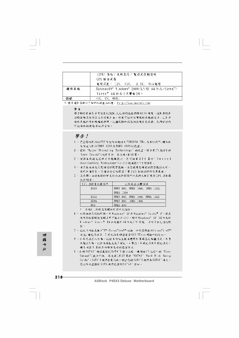
218218218218218ASRock P45X3 Deluxe Motherboard
® ®
®
®
® ®

219219219219219ASRock P45X3 Deluxe Motherboard
®
®
®
® ®
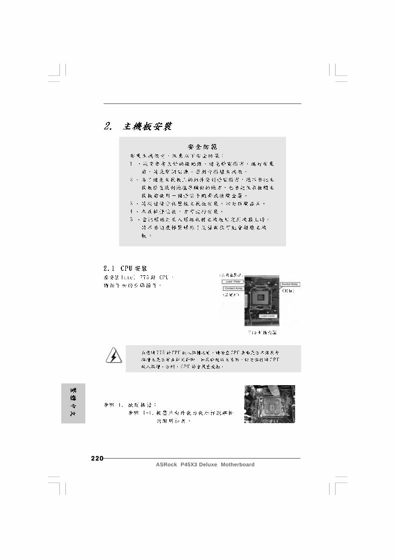
220220220220220ASRock P45X3 Deluxe Motherboard
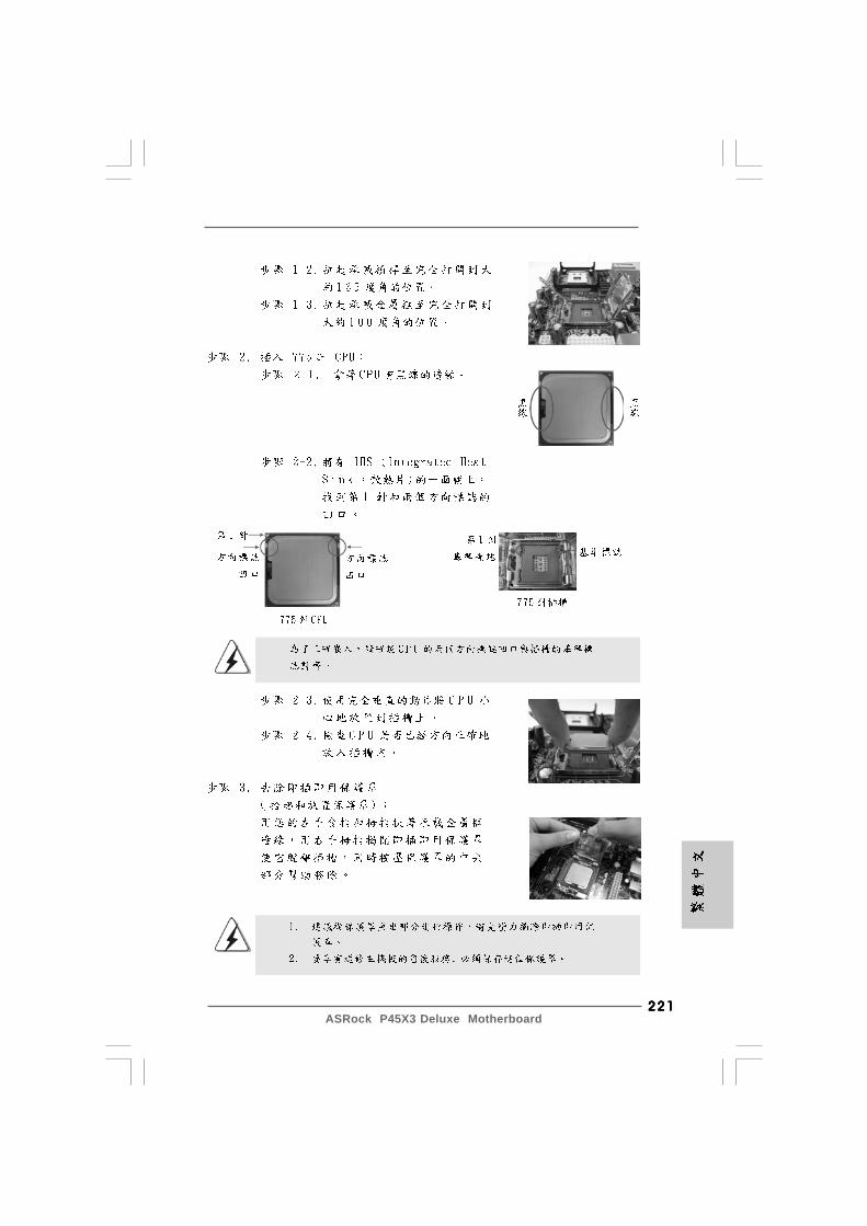
221221221221221ASRock P45X3 Deluxe Motherboard
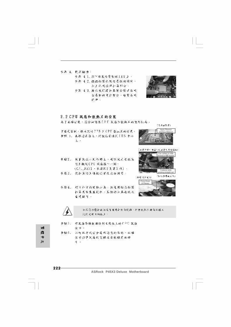
222222222222222ASRock P45X3 Deluxe Motherboard
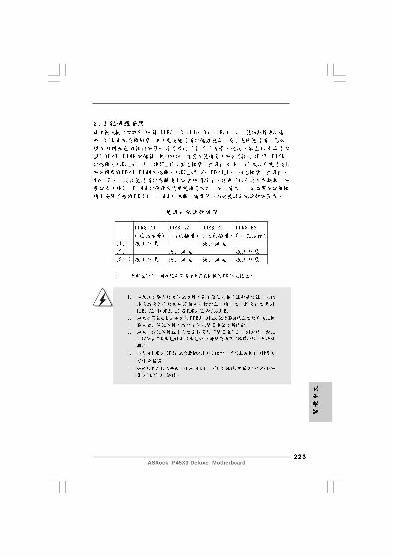
223223223223223ASRock P45X3 Deluxe Motherboard
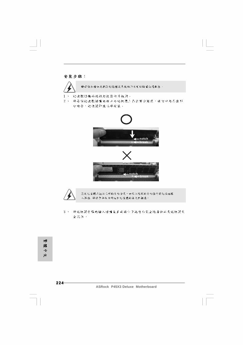
224224224224224ASRock P45X3 Deluxe Motherboard
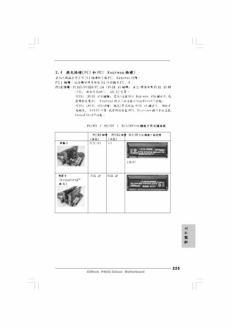
225225225225225ASRock P45X3 Deluxe Motherboard
226226226226226ASRock P45X3 Deluxe Motherboard
®
®

227227227227227ASRock P45X3 Deluxe Motherboard
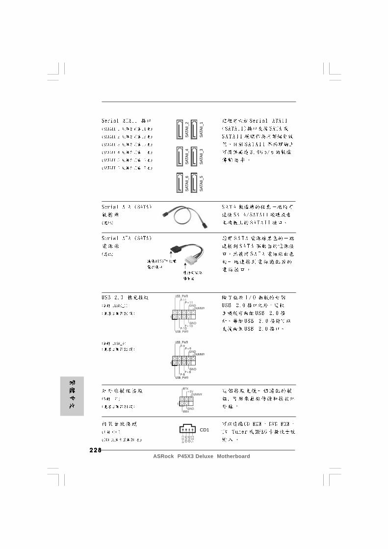
228228228228228ASRock P45X3 Deluxe Motherboard
SATA
II_6
SATA
II_4
SATA
II_2
SATA
II_5
SATA
II_3
SATA
II_1
CD1
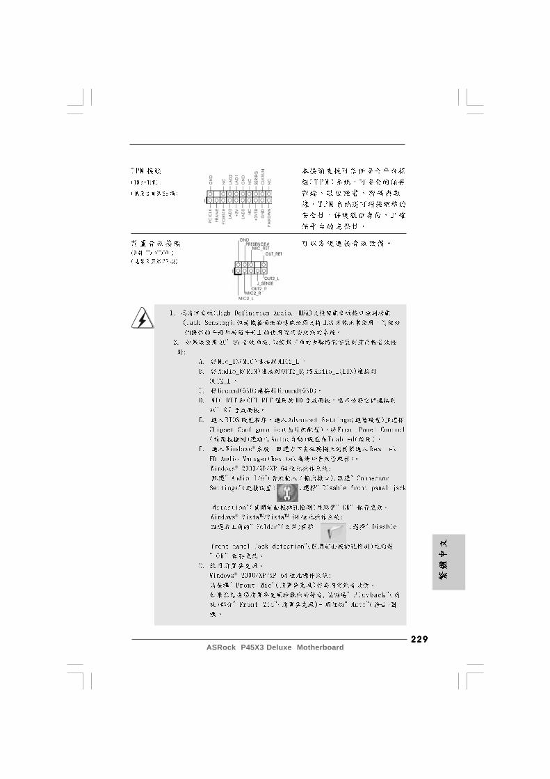
229229229229229ASRock P45X3 Deluxe Motherboard
®
®
®
®
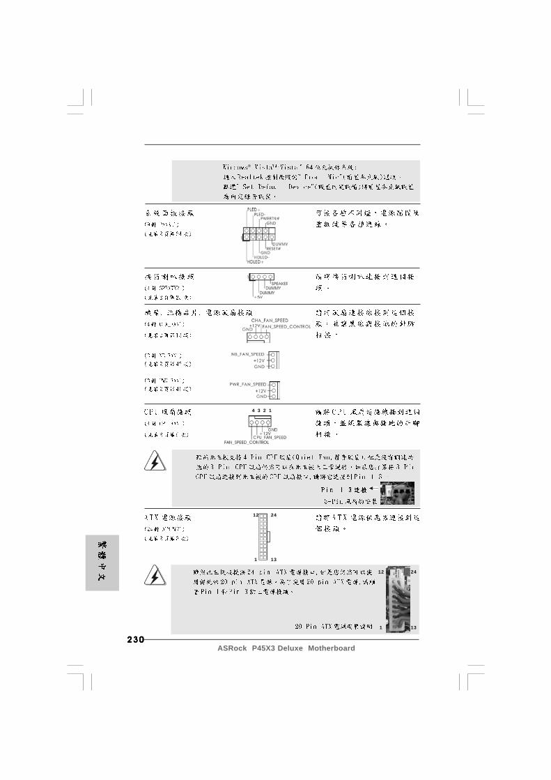
230230230230230ASRock P45X3 Deluxe Motherboard
12
1
24
13
12
1
24
13
4 3 2 1
®
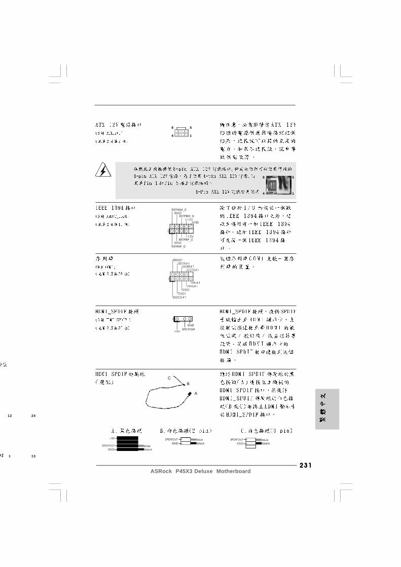
231231231231231ASRock P45X3 Deluxe Motherboard
8 5
4 1
8 5
4 1
12
1
24
13
CB
A

232232232232232ASRock P45X3 Deluxe Motherboard
RESET
clr
CMOS
®
®
® ® ® ®
® ®
233233233233233ASRock P45X3 Deluxe Motherboard
®
®
®
® ®
®
®
®
®
234234234234234ASRock P45X3 Deluxe Motherboard
®
® ®
® ®
® ®
®
®
® ®

235235235235235ASRock P45X3 Deluxe Motherboard
® ® ®