copyright © 2012 elsevier
TRANSCRIPT

Yu, Z., Jaworski, A.J., and Backhaus, S. (2012) Travelling-wave
thermoacoustic electricity generator using an ultra-compliant alternator for
utilization of low-grade thermal energy. Applied Energy, 99 . pp. 135-145.
ISSN 0306-2619 Copyright © 2012 Elsevier A copy can be downloaded for personal non-commercial research or
study, without prior permission or charge
Content must not be changed in any way or reproduced in any
format or medium without the formal permission of the copyright
holder(s)
When referring to this work, full bibliographic details must be given
http://eprints.gla.ac.uk/69764/
Deposited on: 09 September 2013
Enlighten – Research publications by members of the University of Glasgow
http://eprints.gla.ac.uk

Applied Energy 99 (2012) 135–145
Contents lists available at SciVerse ScienceDirect
Applied Energy
journal homepage: www.elsevier .com/locate /apenergy
Travelling-wave thermoacoustic electricity generator using an ultra-compliantalternator for utilization of low-grade thermal energy
Zhibin Yu a, Artur J. Jaworski a,⇑, Scott Backhaus b
a Department of Engineering, University of Leicester, University Road, Leicester LE1 7RH, UKb Los Alamos National Laboratory, Condensed Matter and Thermal Physics Group, Los Alamos, NM 87545, USA
h i g h l i g h t s
" Presented a novel concept of a travelling-wave thermoacoustic electricity generator." Use of ultra-compliant alternator to convert acoustic power to electricity." New acoustic stub matching and phase adjustment techniques modelled and demonstrated." Principles and functionality demonstrated through modelling and experimentation." Guidelines for designing cheap and practical ultra-compliant alternators developed.
a r t i c l e i n f o
Article history:Received 24 January 2011Received in revised form 13 March 2012Accepted 30 April 2012Available online 4 June 2012
Keywords:ThermoacousticsElectricity generatorUltra-complaint alternatorPhase tuning
0306-2619/$ - see front matter � 2012 Elsevier Ltd. Ahttp://dx.doi.org/10.1016/j.apenergy.2012.04.046
⇑ Corresponding author.E-mail address: [email protected] (A.J. Jaworski)
a b s t r a c t
This paper proposes a novel concept of a travelling-wave thermoacoustic electricity generator, whichemploys a looped-tube travelling-wave thermoacoustic engine to convert thermal energy into acousticpower, an ultra-compliant alternator within the engine loop to extract and convert the engine acousticpower to electricity and an acoustic stub matching technique to match the alternator to the engine. Inaddition, a carefully designed cold heat exchanger acts as a phase shifting inertance to improve the per-formance. A simple model has been developed to capture and demonstrate the physics of this new con-cept, while the whole system has been investigated in detail numerically by using a specialized designtool DeltaEC. Based on the current concept, a prototype has been designed, constructed and tested. It usesatmospheric air as the working fluid, a commercially available audio loudspeaker as the electro-dynamictransducer, and inexpensive standard parts as the acoustic resonator. The experimental results have ver-ified the simplified model and the numerical simulations of the practical build. The small-scale inexpen-sive prototype generator produced 11.6 W of electrical power, which shows the potential for developingcheap thermoacoustic electricity generators for energy recovery from waste heat sources. It is concludedthat such concept could be very attractive provided that inexpensive ultra-compliant alternators basedon the standard technology used in audio loudspeakers could be developed. Finally, some guidelines havebeen discussed and proposed for developing such alternators.
� 2012 Elsevier Ltd. All rights reserved.
1. Introduction
Thermoacoustic technologies deal with the thermodynamicconversion between thermal energy and acoustic power by relyingon the so-called thermoacoustic effect. Here, the heat transfer be-tween a gas parcel and solid material, occurring due to their localtemperature difference, can take place at separate locations alongthe solid temperature gradient due to the fluid displacementcaused by the acoustic oscillations. Therefore, the appropriatelyphased pressure and displacement (or velocity) oscillations enable
ll rights reserved.
.
the compressible gas parcel to undergo a useful thermodynamiccycle in the vicinity of a solid material and thus to convert thermalenergy to acoustic power. A variety of thermoacoustic engines(TAEs) have been devised to convert thermal energy to high inten-sity acoustic power using the above thermoacoustic effect [1–5].According to the characteristics of the sound wave present in theseengines, they can be categorized into two types: travelling-waveand standing-wave engines. For the travelling-wave engines, thephase difference between the pressure and velocity oscillations isclose to zero within the thermoacoustic core, while for the stand-ing wave devices, the phase difference is close to 90�; and thesecharacteristics have a major impact on the reversibility and thusefficiency of the associated thermodynamic cycles. The term ‘‘core’’

Nomenclature
A areaa sound speedBl force factorC acoustic compliancecp specific heat at constant pressureF frequencyf thermoacoustic functionj square root of �1K stiffnessk acoustic propagation coefficientL inductancel lengthM moving massQ heat powerP Pressurep acoustic pressure amplitudeR electric/mechanical/acoustic resistancer radiusT temperatureU volumetric velocityu velocityV voltage; volumeW powerX excursionZ acoustic impedance
c ratio of specific heat capacitiesd penetration depthg efficiencyn coil displacementq densityr Prandtl numbers temperature ratio/ porosity; phase anglex angular frequency
Subscripta acousticalt alternatorchx cold heat exchangere electricalfb feedbackg gask related to thermal penetrationM meanm mechanicalstub related to stubt thermalt viscous1 first order variable
136 Z. Yu et al. / Applied Energy 99 (2012) 135–145
denotes an arrangement of the thermoacoustic regenerator/stackand adjacent heat exchangers.
Swift [1] designed and tested a large scale standing-wave ther-moacoustic engine, which uses 13.8 bar helium as the working gasand can deliver 630 W of acoustic power to the external acousticload, converting the heat (thermal) energy into acoustic power ata thermal efficiency of 9%. There are also several other prototypesof standing-wave engines of different sizes or configurations whichhave been studied by various researchers. However, the standing-wave thermoacoustic engines work on an intrinsically irreversiblethermodynamic cycle. Their thermal efficiency ratio of acousticpower produced to heat input has thus far been limited to less than20%.
Ceperley [6] was first to point out that when a travelling soundwave passes though the regenerator with axial temperature gradi-ent, the interaction between the gas and the solid material leads toa Stirling-like thermodynamic cycle. Yazaki et al. [2] were the firstto demonstrate such an engine, but at low efficiency due to the lowacoustic impedance within the thermoacoustic core, which causedlarge viscous losses resulting from high acoustic velocities. Muchlater, based on a compact acoustic network, Backhaus and Swift[3] proposed a new type of thermoacoustic engine which employsan inherently reversible Stirling cycle in the regenerator and uti-lised a high acoustic impedance to suppress the high acoustic loss.Based on a more complex acoustic network, compared to previousattempts [2], their thermoacoustic Stirling heat engine (TASHE)demonstrated a higher thermal efficiency of 30%, correspondingto 41% of the Carnot efficiency. Recently, for the same type of en-gine, a new record of 49% of Carnot efficiency has been set by Tijaniand Spoelstra [7].
The devices mentioned above were designed to utilise a hightemperature source at the engine’s hot heat exchanger (or in otherwords a high temperature difference along the regenerator). A sep-arate challenge, however, is the engine excitation by as small tem-perature gradients as possible, because this could open the newopportunities for utilisation of low grade waste heat. For example,de Blok’s travelling-wave thermoacoustic engine [5] with a
travelling wave feedback pipe starts to operate at a temperaturedifference of only 65 K. Recently, his multistage version of this typeof engine was able to operate at the temperature difference of only40 K at each stage [8]. Due to their simple configuration, with nomoving mechanical components, TAEs show the potential fordeveloping reliable, low-cost and environmentally-friendly energyconversion devices for utilizing solar energy or industrial wasteheat.
The acoustic power generated by the TAEs can be converted toelectricity through an electro-dynamic transduction mechanism.Depending on the range of the acoustic impedance of these elec-tro-dynamic transducers, the method of coupling them to TAEs dif-fers. So far, several thermoacoustic generator prototypes have beenbuilt and tested. A compact travelling-wave thermoacoustic gener-ator prototype has been developed for electricity generationaboard spacecraft by integrating the TASHE concept with a linearalternator [9]. Instead of using a lossy standing-wave acoustic res-onator, the reactive impedance (i.e. the moving mass) of the linearalternator created a resonance with the compliant gas spring of thethermoacoustic Stirling engine’s volume, while the real impedanceof the linear alternator extracted the useful acoustic power. At itsmost efficient operating point, the device achieved a thermal toelectric conversion efficiency of 18%. A linear alternator can alsobe coupled to a conventional thermoacoustic Stirling engine asan acoustic load where the acoustic resonance is provided by thestanding-wave acoustic resonator. Recent work indicated that thistype of combination can achieve a thermal to electric conversionefficiency of 15% [10]. Other alternatives include integrating a pie-zoelectric generator with a TAE [11].
In the TAE/alternator combinations mentioned above, the linearalternators had very high acoustic impedance (i.e. large force andsmall displacement) at the operating frequency of the systemand needed to be installed at a high impedance region of the acous-tic field. In acoustics, they are also referred to as ‘‘noncompliant’’transducers. The high impedance generally leads to a high pressuredrop. Most linear alternators usually adopt a clearance seal whichis essentially a radial gap between the cylinder and piston as small

Table 1Specifications of the loudspeaker (alternator).
Nominal Measured Deviation
Z. Yu et al. / Applied Energy 99 (2012) 135–145 137
as 10 lm to avoid friction losses [9]. However this leads also tohigh seal losses. Although the clearance is small, the gas can stillpass through this gap (a form of acoustic streaming) when thepressure difference between two sides of the piston is high. Insome arrangements, for example, the piston faces the thermoacou-stic engine, while its back is enclosed. Such streaming will accumu-late the gas on one side of the piston and, as a result, the meanpressure at two sides of the piston will not be equal, which cancause an excessive piston drift. Furthermore, such linear alterna-tors tend to be very expensive because the clearance seal requiresa costly manufacture processes. This counteracts the frequentlymentioned advantages of thermoacoustic technology such as sim-plicity and low cost. From the viewpoint of potential commercial-ization, such an expensive combination is unlikely to be viablewhen competing with the generators based on conventional Stir-ling engines which can also utilize low temperature heat sourcesbut have higher conversion efficiencies.
However, from the theoretical viewpoint, it is also possible tocombine TAEs with low impedance (i.e. small force and large dis-placement) transducers. Such low impedance transducers are alsoreferred to as ‘‘ultra-compliant’’ transducers. This combination hasseveral advantages compared to its high impedance counterpartsmentioned above. Installing such alternators in a low impedanceregion avoids the technical problems associated with the highimpedance transducers because the required pressure drop ismuch lower. This allows replacing the clearance seal with a ‘‘her-metic’’ seal which eliminates the seal loss and the possible pistondrift due to the streaming though the clearance seal present in con-ventional linear alternators. In addition, in the engine concept pro-posed in this paper, such a ‘‘hermetic’’ seal allows suppressing theGedeon streaming that usually exists within the loop type ther-moacoustic systems�. The manufacturing costs of such ultra-compli-ant alternators could be much lower because they could potentiallyuse the technologies which have been widely used by audio loud-speaker manufacturers. However, very little research attention hasbeen devoted to such combinations, partly because there are no suchultra-compliant linear alternators available in the market yet, exceptthe audio loudspeakers which might be treated as low impedancealternators because they usually have relatively small moving massand stiffness. However, it should be noted that, the loudspeakers aredesigned for high audio quality rather than to convert acousticpower to electricity in an efficient manner, and they do not matchexactly the requirements of a thermoacoustic generator. For exam-ple, they have a relatively low power transduction efficiency, a frag-ile paper cone, and a limited stroke.
Integrating ultra-compliant alternators with TAEs leads to newchallenges and design considerations, which the current researchaims to address. A new concept for coupling such an alternatorto a TAE is proposed, and this has been investigated in detail, boththeoretically and numerically. Based on this novel concept, a small-scale prototype of an inexpensive thermoacoustic generator hasbeen built and tested. It has produced useful amounts of electricitywith reasonable conversion efficiency. The experimental resultshave verified the modelling. Furthermore, the ultimate goal of thiswork is to raise the awareness of both the research community andindustry regarding the potential opportunities to develop inexpen-sive thermoacoustic generators for energy recovery from wasteheat sources, and that there is a demand for low cost and low
� To address one of the referee comments, one can imagine a low impedancealternator with a clearance seal or a high impedance alternator with a ‘‘hermetic’’seal. However, neither of them would be practical: the former would lose theadvantage of stopping Gedeon streaming and eliminating piston drift by having ahermetic seal, both of which are achievable due to a small pressure drop across themembrane, while the latter would require a sturdy membrane resistant to fatigue –i.e. another serious engineering issue.
impedance alternators which could be manufactured using themature technologies being widely used by loudspeaker manufac-turers. Furthermore, from the viewpoint of a better coupling withTAEs, some guidelines for developing such ultra-compliant alterna-tors have been discussed and summarized based on the researchresults obtained.
2. Concept and simplified model
As described in the introduction, there are different types ofthermoacoustic engines. Standing-wave engines have a very sim-ple linear configuration but relatively low efficiencies [1]. The pres-sure difference across the alternator’s diaphragm has a highamplitude when the alternator is coupled to the standing-wavethermoacoustic engine. Such working conditions typically demandthe application of high impedance linear alternators because theirhigh mass/high stiffness construction allows handling high pres-sures across the diaphragm which is typically a sturdy metal pis-ton. Ultra-compliant alternators would be a bad choice in thissituation due to the fact that a relatively flexible diaphragm wouldbe unable to handle the very high pressure differentials across.Torus type travelling wave engines have high thermal efficiencies[3,9], and the generator based on this type of engine has shown ahigh generator efficiency [9]. However, the ultra-compliant alter-nator could not provide the large reactive impedance to maintainthe acoustic resonance for the torus as shown in Ref. [9]. It is pos-sible to install such an ultra-compliant alternator in the thermoa-coustic engine through a side branch pipe as shown in Ref. [10].This however requires the alternator to handle a high pressuredrop and this configuration is not suitable for such a low imped-ance ultra-compliant alternator.
A looped tube thermoacoustic engine is another type of a trav-elling-wave engine [2]. Its performance is better than the standing-wave engine [1], while the configuration is still relatively simple.Using this configuration, it is possible to install the ultra-compliantalternator in the near-travelling wave region within the looped-tube resonator. In this way, the pressure difference across thealternator diaphragm can be significantly reduced. This arrange-ment also helps to suppress the acoustic streaming which is in-duced by the secondary mass flow and could cause heat lossesfrom a hot heat exchanger.
As mentioned in the introduction, currently there are no ultra-compliant alternators available on the market. Therefore in this re-search it has been decided to use an audio loudspeaker as anapproximation of an ultra-compliant alternator, although it isrecognised that audio loudspeakers would not match exactly therequirements of a thermoacoustic electricity generator. Accordingto the loudspeaker (or in this case alternator) linear theory [12],to achieve a high transduction efficiency, the alternator shouldhave a high force factor Bl, low mechanical resistance Rm, andlow electrical resistance Re. Furthermore, for a given frequency,the electrical power production capacity also depends on the
F (Hz) 75 62.0 ±0.1 (±0.2%)Bl (N/A) 10.8 9.6 ±0.3 (±3%)Le (mH) 0.6 0.479 ±0.002 (±4.1%)Re (X) 5.4 5.41 ±0.1 (±1.8%)Mm (g) 14 17.0 ±0.3 (±2%)Km (N/m) 2778 2621 ±10 (±4%)Rm (kg/s) 0.64 0.96 ±0.02 (±2%)X (mm) ±6Aalt (cm2) 132

Fig. 1. Schematic of the demonstrator unit and the lumped acoustic circuit.
138 Z. Yu et al. / Applied Energy 99 (2012) 135–145
excursion of the alternator; therefore, a high excursion is preferred.According to these criteria, a B&C 6PS38 woofer (manufactured byB&C speakers) was selected. Its specifications and the measuredThiele/Small parameters are summarized in Table 1 [13].
The present concept of the thermoacoustic electricity generatoris shown schematically in Fig. 1. The thermoacoustic core consistsof a cold heat exchanger (CHX), regenerator (REG) and hot heat ex-changer (HHX). The core is in essence an acoustic power amplifier[14]. The overall power flow is such that part of the acoustic powergenerated in the core is extracted by the alternator, while theremaining part is fed into the cold end of the regenerator throughthe feedback pipe (FBP) and is then amplified by the regeneratorwith a steep temperature gradient in the direction of sound prop-agation which causes a sharp increase in the volumetric velocity(the above mentioned amplification effect). The regenerator has across sectional area A much larger than that of feedback pipe, in or-der to improve the generator performance by having |Z|� qMa/A[3]. The change in A requires two tapered sections, likely to causeflow separations and thus significant streaming and heat leaks[15]. To suppress the streaming, two flow straighteners (severalcoarse mesh discs) are installed – c.f. the dotted lines as shownin Fig. 1.
Below the thermoacoustic core, there is a thermal buffer tube(TBT), of which one end connects to the hot heat exchanger; whilethe other connects to the secondary cold heat exchanger that pre-vents a heat leak to the alternator housing. The alternator is in-stalled just after the secondary cold heat exchanger, and isenclosed in a housing. The acoustic power is extracted by the alter-nator immediately after it is produced in the thermoacoustic core.The alternator introduces an acoustic load to the thermoacousticengine, which alters the acoustic field within it. An acoustically un-matched load generates an acoustic reflection and a high standingwave ratio in the acoustic feedback pipe and thus causes largeacoustic losses. To extract the acoustic power in an efficient man-ner through the alternator and reduce the acoustic losses withinthe feedback pipe, the load (alternator) has to be matched withthe engine’s acoustic network. This is achieved by applying a tech-nique of ‘‘stub-matching’’, very similar to that routinely used inmicrowave electronic circuits. Here an acoustic stub has beenintroduced to the engine as shown in Fig. 1. It is a side branch pipewith the same diameter as the feedback pipe, and its length can bevaried by moving a piston so that the fine tuning effect can be ob-tained within the experiments. In principle, acoustic reflections
introduced by the alternator can be cancelled out by adding anequal and opposite reflection from the side stub.
The matching stub should be attached to the wave guide at thelocation close to the load as schematically shown in Fig. 1. Theoptimal location for the stub will be discussed later. After the sidestub, the long feedback pipe (FBP) connects back to the thermoa-coustic core to the top end of the cold heat exchanger, throughwhich part of the acoustic power is fed back to the thermoacousticcore for amplification.
In addition to the diagram of the physical layout, an equivalentlumped electrical circuit is presented in the inset of Fig. 1 to pro-vide a further physical understanding of the generator’s operation.According to the linear thermoacoustic theory [16], Eq. (1) quanti-tatively describes the interaction between the acoustic and tem-perature fields (i.e. the thermoacoustic effect).
1þðc�1Þfk½ �p1þcp1
x2
ddx
1� fvqM
� �� a2
x2
fk� fv1�r
1TM
dTM
dxdp1
dx¼0: ð1Þ
Here, p, U, T, q, and c are the pressure, volumetric velocity, temper-ature, density and the ratio of specific heat capacities of the gas,respectively; x and a are the angular frequency and sound speedof the acoustic wave; fk and fv are the spatially averaged thermaland viscous functions, respectively. fk and fv and are given in [16]in detail. Subscript ‘‘1’’ indicates the first order of a variable, whichusually has a complex amplitude. For the convenience of numericalcalculations, Eq. (1) can be written as:
dp1
dx¼ � jxqM=A
1� fvU1; ð2Þ
dU1
dx¼ � jxA
cpM½1þ ðc� 1Þfk�p1 þ
ðfk � fvÞð1� fvÞð1� rÞ
dTM
TMdxU1: ð3Þ
In essence, Eqs. (2) and (3) are the thermoacoustic version ofmomentum and continuity equations. The time-averaged acousticpower dWa produced in a length dx of the channel can be written inthe complex notation in the general form as
dWa
dx¼ 1
2Re ~U1
dp1
dxþ ~p1
dU1
dx
� �ð4Þ
where ‘‘�’’ indicates a complex conjugate. Re[ ] denotes the real partof a complex number. Eq. (4) can be written as
dWa
dx¼ �Rv
2jU1j2 �
12Rkjp1j
2 þ 12
Re½g~p1U1�: ð5Þ
Viscous resistance per unit length of the channel, Rv, thermal-relaxation conductance per unit length of the channel, 1/Rk, andthe complex gain constant for the volume flow rate, g, are definedas follows:
Rv ¼xqm
Ag
Im½�fv �j1� fv j2
; ð6Þ
1Rk¼ c� 1
cxAg
pMIm½�fk�; ð7Þ
and
g ¼ ðfk � fvÞð1� fvÞð1� rÞ
1TM
dTM
dx: ð8Þ
Ag is the cross sectional area of gas channels in the regenerator. Fur-thermore, Ag ¼ /A, where / and A are porosity and cross sectionalarea of the regenerator, respectively. In the regenerator, the viscousloss is much more important than the thermal-relaxation loss.Therefore, the regenerator is simplified and modelled as a combina-tion of resistance Rreg and a current source (s � 1)U1,c as shown in

Z. Yu et al. / Applied Energy 99 (2012) 135–145 139
Fig. 1. Here, s=Th/Tc,, while Th and Tc are the temperatures at twoends of the regenerators, respectively.
In the acoustic domain, the impedance of the alternator can bewritten as [13]
Zalt ¼DpU1¼ 1
A2alt
ðBlÞ2
ðRe þ RL þ jxLeÞþ Rm þ j xMm �
Km
x
� �" #ð9Þ
Here Dp is the pressure drop across the diaphragm, and RL is theload resistance. According to the parameters shown in Table 1, xLe
is much less than Re or RL, therefore, neglecting the inductance ofthe coil leads to
Zalt ¼1
A2alt
ðBlÞ2
Re þ RLþ Rm
!þ j xMm �
Km
x
� �" #: ð10Þ
The right hand side of Eq. (9) shows that the alternator intro-duces an acoustic resistance Ralt (i.e., the total effect of coil resis-tance Re, load resistance RL, and the mechanical resistance Rm), aninertance Lalt (i.e., the inertial effect of the mass of the coil andcone), and a compliance Calt, (i.e., the spring effect) to the loop.These three components are connected in the equivalent circuitin series as shown in Fig. 1. The acoustic power extracted by Ralt
is mostly converted into electric power, part of which is deliveredto RL, while the rest is dissipated by the coil resistance. U1 is con-stant at the two sides of the alternator diaphragm, while |p1| dropsdue to the power extraction. This pressure drop is much smallerthan that in conventional designs because the reactive part of theimpedance is very small even when the alternator is off resonanceby a few Hz:
xMm �Km
x
� �� ðBlÞ2
Re þ RLþ Rm
!: ð11Þ
Although the pressure drop is small, the installation of the alter-nator will still modify the preferred acoustic field along the loopedengine [2]. This will cause a drop of |Z| at two sides of the alterna-tor. To tune Z for minimum dissipation in the feedback pipe, theside-branch matching stub needs to compensate for the alterna-tor’s effect on the acoustic field.
For a section of acoustic duct, the relationship between the in-put Z1 and output acoustic impedance Z2 can be rewritten as [17]:
Z1 ¼ Z0Z2 þ jZ0 tan klZ0 þ jZ2 tan kl
: ð12Þ
Here, l is the length of the duct, k = 2p/k is the acoustic propagationcoefficient, and Z0 is the characteristic impedance of the duct and isdefined as
Z0 ¼qMa
A: ð13Þ
The stub is essentially a section of an acoustic duct with a closedend, i.e. Z2 =1. Therefore, the input acoustic impedance of the stubcan be approximately written as
Zstub � �jqMa
Acot kl: ð14Þ
Usually, the stub length is much less than k/4 so that kl < p/2.For 0.5 < kl < 1, applying the second order approximation on cotan-gent function on the right hand side of Eq. (14) leads to
Zstub � �j1
xCsþ j
xLs
3: ð15Þ
Here,
Cs ¼V
qMa2 ¼V
cPM; ð16Þ
and
Ls ¼lqM
A: ð17Þ
Therefore, the stub can be modelled as a combination of acous-tic compliance Cs and inertance Ls in series, as shown in Fig. 1. Con-sidering 1/xCs�xLs so that the stub injects a reactive DU1 intothe loop that lags p1 by almost 90� without changing |p1| at thejunction. Consequently, it introduces a sharp increase of |Z| andthe phase angle, which compensates for the effect of the alternator.
The rest of the feedback pipe is just a lossy acoustic waveguide.Each unit section can be modelled as a combination of resistanceRfb, inertance Lfb and compliance Cfb, which can also be calculatedaccording to Eqs. (16) and (17). It should be noted that, as willbe described later in Section 4, the cold heat exchanger has a verylow porosity of 10%, while it has a relatively long length of 90 mm.Compared with the large cross-sectional area of the thermoacou-stic core, the CHX effectively introduces a long but small cross-sec-tion channel locally into the loop. Therefore from the acousticspoint of view, the CHX introduces a noticeable inertance effect inaddition to the usual acoustic resistance Rchx. This additional iner-tance effect is modelled as Lchx as shown in Fig. 1 and is also dem-onstrated by the numerical results as shown in Fig. 2d later in thispaper. Essentially, such an inertance effect introduces a pressuredrop Dp that lags U1 by almost 90� [18]. This also provides a phasechange helping to create the preferred condition for an efficientregenerator (i.e. U1 leads p1 at the cold end and U1 lags p1 at thehot end [3]). Although its inertance effect is much smaller thanthe classic ‘‘inertance tubes’’ which are commonly used in pulse-tube cooler systems, the interesting attempt here is to demonstratethat it is feasible to combine the inertance phase shifter with heatexchangers, which is potentially an advantage for designing morecompact thermoacoustic systems.
3. Design simulations
The simplified model described above provides a very usefulqualitative understanding of the behavior of the thermoacousticelectricity generator considered in this paper. However it is admit-tedly a complex system involving acoustic, mechanical and electri-cal components. Therefore for a quantitative analysis a morespecialised design tool referred to as Design Environment forLow-amplitude ThermoAcoustic Energy Conversion (DeltaEC) isemployed. It is a computer programme, widely used for analysingthermoacoustic applications [19]. It can be used in the design pro-cess in order to optimise a thermoacoustic system from the pointof view of the required performance, or to predict the performanceof an existing build of a thermoacoustic device with the view offurther debugging. DeltaEC integrates numerically the acousticwave equation and energy equation segment by segment through-out the whole device based on the low amplitude acoustic approx-imation and the sinusoidal time dependence of the variables [16].
The design and optimisation processes are quite involved andwould require a separate paper to describe all the detailed steps.However these are outside the scope of this paper. Therefore, forconvenience, the simulation results discussed in this section arebased on the final design of the prototype, with dimensions givenin the next section. This will allow comparisons between theexperiments and simulations to verify the model. However, itshould be noted that, some compromises had to be made to utilisethe available standard parts in order to reduce the cost of the pro-totype. This means that the final prototype design is not fully opti-mized from the theoretical point of view, and there are still someopportunities for further improvement of performance if for exam-ple bespoke parts were to be made (e.g. pipes of non-standard

Fig. 2. Pressure amplitude (a), volumetric velocity (b), acoustic impedance (c), phase angle (d) and acoustic power flow (e) along the generator.
140 Z. Yu et al. / Applied Energy 99 (2012) 135–145
diameters). Furthermore, atmospheric air is used as working gas inorder to simplify the construction and operation of the presentprototype.
For the purpose of comparison with the experiments, the dis-placement of the coil within the alternator is set to 6.25 mm as aboundary condition, which is also easy to be accurately controlledin the experiments. To achieve this displacement, the input heatpower is about 434 W in the simulation. Although the displace-ment is slightly bigger than the nominal maximum excursion ofthe alternator, the measurement shows that the distortion of theoutput voltage is negligible. The load resistance is set to 15.6 X.The working gas is air at atmospheric pressure. The working fre-quency is 70 Hz, which is a compromise between the requirementsfrom the alternator (i.e. at resonance) and dimensions of the regen-erator (i.e. matching the hydraulic radius). The principles for opti-mization were as follows: Firstly, the regenerator should work in atravelling-wave condition. Secondly, a near travelling wave has tobe achieved in the feedback pipe to reduce the dissipation. Onetypical case of the simulation is shown in Fig. 2.
Fig. 2a shows the pressure amplitude distribution along theloop (which is around 4.25 m long). There are two maxima andtwo minima of pressure amplitude along the loop and two sharppressure drops. One drop is along the regenerator (about 450 Pa).The other is at the alternator which indicates that the alternatorextracts a considerable acoustic power. Looking back to the simpli-fied model as shown in Fig. 1, the first pressure drop is caused bythe flow resistance of the regenerator Rreg, while the second is obvi-ously caused by the acoustic resistance Ralt introduced by the alter-nator. The standing wave ratio within the loop can be estimated bythe ratio of the maximum over minimum pressure amplitudewhich, as expected, is relatively small (about 2.1). Furthermore,the acoustic stub does not cause a change of pressure amplitude,while it changes the slope at which pressure amplitude increases.The pressure amplitude changes smoothly along all other parts.
Fig. 2b shows the distribution of volumetric velocity along theloop. There are also two maxima and two minima along the loop.One maximum is in between the alternator and the stub, and theother is near the end of the feedback pipe where the minimumof the pressure amplitude is located. One minimum of the volu-metric velocity is at the cold end of the regenerator, while theother is close to the middle of the feedback pipe. The small volu-metric velocity within the regenerator is preferred to avoid highviscous dissipation, which is one of the design strategies behindthe current concept. It can also be seen that the volumetric velocityincreases significantly along the regenerator. This is due to thesharp temperature gradient along the regenerator. This is the rea-son why the regenerator is modelled as a current source. Further-more, at the location of the stub, there is a sudden decrease of thevolumetric velocity. This indicates that the stub shunts part of thevolumetric velocity away from the looped resonator. Along allother parts, the volumetric velocity changes smoothly.
Fig. 2c shows the acoustic impedance along the loop. It can beseen that the acoustic impedance is highest at the cold end ofthe regenerator (|Z| � 5qMa/A). The impedance drops quickly be-cause the pressure amplitude decreases (see Fig. 2a) while the vol-umetric velocity increases sharply from the cold to the hot end ofthe regenerator (see Fig. 2b). The alternator causes a sudden dropof acoustic impedance due to the fact that the volumetric velocitiesat two sides of the alternator are the same, while the pressureamplitude drops significantly due to the acoustic power extraction.The stub introduces a sudden increase of the acoustic impedancealong the loop. This is because the pressure amplitude at the stubjunction is constant, while the volumetric velocity has beenshunted partly to the stub due to the stub’s reactive impedanceas shown in Fig. 1. It is very clear that the stub cancels out (almostperfectly) the acoustic impedance drop caused by the alternator.This is the essence of the stub matching idea behind the currentconcept.

Fig. 4. Photograph of the cold heat exchanger.
Fig. 5. Photograph of the hot heat exchanger.
Z. Yu et al. / Applied Energy 99 (2012) 135–145 141
From Fig. 2c, one can also find that the alternator is very close tothe minimum of acoustic impedance. This is also a carefully de-signed feature of the rig, introduced to obtain a sufficient volumet-ric velocity to drive the alternator to the maximum excursionwhich subsequently maximizes the electrical power output. Thelocation of the stub has also been optimised in the model. As dis-cussed above, it should be close to the acoustic loads, which in thissystem are the alternator and the feedback pipe’s (FBP) acousticresistance. After a careful simulation process, it has been locatedabout 33 cm away from the alternator. From Fig. 2c, it can alsobe found that 0.6 < |Z| < 1.6 qMa/A along FBP. Therefore, the dissi-pation in the FBP has also been minimized.
Fig. 2d shows the phase difference between pressure and veloc-ity oscillation along the pipe. It can be found that the regenerator isat a near travelling-wave location. The phase angle decreases rap-idly after alternator till the junction with stub. The stub introducesa sharp increase of phase angle (D/ = 37�) to counteract this sharpphase angle decrease. Furthermore, it can also be seen that CHX’sphase-shifting inertance Lchx (which has a very low porosity ofonly10%, as will be described in the next section) introduces aphase change D/ = �7� helping to create the preferred conditionfor an efficient regenerator (i.e. U1 leads p1 at the cold end andU1 lags p1 at the hot end [2]). The rest of FBP is just an acousticwaveguide. After optimization, FBP also achieves a near travellingwave condition (i.e. �21�</<21�).
Fig. 2e shows the acoustic power flow along the loop. It can befound that around 37 W of acoustic power is fed into the cold heatexchanger which dissipates around 1.4 W. The remaining 35.6 W isfed into the cold end of the regenerator. Within the regenerator,the acoustic power is amplified to around 64.3 W which is the levelof acoustic power flowing out from the hot end of the regenerator.The hot heat exchanger and thermal buffer tube dissipate around4.3 W. The alternator extracts about 19.3 W of acoustic power.The feedback pipe dissipates about 3.6 W. In this simulation, thealternator produces 10.3 W of electricity. As mentioned above,the required input heat is 434 W for this case. Therefore, the calcu-lated thermal-to-acoustic efficiency gt-a = 4.4%, acoustic-to-electricefficiency ga-e = 53.4%, and thermal-to-electric efficiency gt-
e = 2.4%.
4. Experimental apparatus
A prototype thermoacoustic generator has been constructedaccording to the present concept and the detailed modelling re-sults. Fig. 3 is a photograph of the prototype and the instrumenta-tion used in the experiments. As shown in Fig. 4, the cold heatexchanger is made out of a round aluminium block, which is
CHX
Alternator
Regenerator
Stub Feedback pipe
Lock-in amplifier
HHX TBT
Fig. 3. Photograph of the thermoacoustic generator prototype.
90 mm long and has 110 mm diameter. Gas passages are made inthe form of 45 holes with the diameter of 5 mm, drilled parallelto the heat exchanger’s centre-line. Twelve holes with the diame-ter of 6 mm are drilled perpendicular to the heat exchanger axis topass cooling water. A PCB pressure transducer (model 112A22) isinstalled just above the cold heat exchanger, which is indicatedas P3 in Fig. 1.
The regenerator is made out of stainless screen disks (110 mmin diameter), with the mesh number 34 and the wire diameter0.254 mm. Fourty two discs have been piled up in a stainless steelcan which has a wall thickness of 2 mm. The disks form a 21 mmlong regenerator. Consequently, the obtained porosity and hydrau-lic radius are 73.3% and 175 lm, respectively. Three Type-K ther-mocouples (TC-Direct model 408-119) are installed along theregenerator. The distance between each of the two adjacent ther-mocouples is 10.5 mm. They monitor the temperature profile alongthe axis of the regenerator, as well as the temperature differencebetween the two ends of the regenerator. They are denoted byT2–T4 in Fig. 1.
The hot heat exchanger is made using a standard cable heatermanufactured by WATLOW. It has 3.17 mm diameter and a length

Table 2Comparison between the simulation and measurements.
Simulation Experiments
|n| (mm) 6.25 6.25RL (X) 15.6 15.6Q (W) 434 500|p1| (Pa) 3780 4222|p2| (Pa) 2644 2947|p3| (Pa) 4771 4638|VL| (V) 18.1 14.6Wa (W) 19.3 15.24We (W) 10.3 7.1gt-a (%) 4.4 3.0ga-e (%) 53.4 46.5gt-e (%) 2.4 1.4
142 Z. Yu et al. / Applied Energy 99 (2012) 135–145
of 2.4 m. Its rated power is 1000 W and the rated voltage is 240 V.Fig. 5 is the photograph of the hot heat exchanger when it is in-stalled in the engine. It was wound into a spiral configuration withtwo layers. Several coarse mesh discs were inserted in betweenthese two layers to enhance the heat transfer between the airand heater. It is powered by a transformer which can adjust thevoltage in the range of 0–240 V. One Type-K thermocouple is in-stalled in the heater to measure the surface temperature of theheater, and it is denoted by T1 in Fig. 1.
Below the hot heat exchanger, there is a short thermal buffertube, which is a section of stainless steel pipe (ID = 110 mm) witha length of 80 mm, and a wall thickness of 2 mm. The 110 mmdiameter buffer tube connects to a smaller buffer tube via a shorttransition cone, which reduces the diameter from 110 mm to54 mm over a distance of 54 mm. The small diameter section isaround 160 mm long and has the internal diameter of 55 mm (asection of standard stainless steel 2-in. tube, with 2.77 mm wallthickness). To reduce heat losses, the regenerator, hot heat exchan-ger and the thermal buffer tube are enclosed within an insulationblanket. The other end of the thermal buffer tube connects to thesecondary cold heat exchanger. A car radiator matrix is tightly fit-ted within the 2-in. pipe to take heat from the hot gas, and there isa water jacket outside the pipe to take the heat away by the run-ning cold water. A short section of 2-in. stainless tube with a lengthof 90 mm connects the secondary cold heat exchanger and thealternator housing.
The alternator is mounted on the bottom flange of the housing;the cone facing downwards. The bottom flange has a small glasswindow (50 mm diameter), which is an optical access for the laserdisplacement sensor (Keyence LK-G152) to measure the displace-ment of the alternator diaphragm. It has a standoff distance of150 mm, and a measuring range of ±40 mm. The sampling fre-quency is 50 kHz and the resolution is 0.5 lm. Two PCB pressuretransducers (model 112A22) have been used to measure the pres-sures behind and in front of the alternator diaphragm (marked asP1 and P2 in Fig. 1). Another Type-K thermocouple is installed justabove the alternator to monitor the local gas temperature to en-sure the alternator works within the rated temperature range.
The remaining part of the rig is the 3.65 m long feedback tubewhich connects back to the cold heat exchanger through a transi-tion cone (54 mm in length). Because the engine is designed tooperate with air at atmospheric pressure, the maximum pressuredifference between the inside and the outside of the resonator cor-responds to the acoustic pressure, which is usually less than0.1 bar. Therefore, the feedback pipe is made of standard 2-in.PVC pipe and 90� bends (Class E, OD: 60.3 mm, thickness4.5 mm) instead of a metal pipe to reduce cost. The total lengthof the loop is about 4.25 m. About 33 cm away from the alternatorhousing, an acoustic stub tube (680 mm in length) is connected tothe resonator to improve the impedance matching between thealternator and engine as already discussed in the section describ-ing the modelling aspects.
A high power variable resistor is utilized as an electrical load forthe alternator to extract electrical power. The voltage differenceand the current flowing through the load resistor are measuredusing a standard voltmeter (with the resolution of 0.001 V) andammeter (with the resolution of 0.01 A). As a result, the electricalpower extracted by the load resistor is deduced. The output fromthe pressure and displacement sensors together with the voltagedrop VL on the load resistor are recorded directly using a computeracquisition card (OMB-DAQTEM 14). The phase angles betweenthese signals are measured by SR830 DSP lock-in amplifier withan accuracy of 0.01�. All of the pressure sensors have a resolutionof 7 Pa, and have been carefully calibrated prior to measurements.The pressure sensors have been interchanged to double check theirreliability.
5. Experimental results and discussion
With the terminals of the alternator open (i.e. RL =1), the gen-erator begins to oscillate when the temperature difference at twoends of the regenerator reaches about 120 K. To achieve|n| = 6.25 mm at the alternator (when RL = 15.6 X and stublength = 0.68 m), the calculated Q = 434 W, while the measuredQ = 500 W. The difference of 66 W is estimated from experimentsas the heat losses to the ambient. The measured pressure ampli-tude is |P3| = 4841 Pa. For the most efficient case, the measuredWe = 7.1 W with a thermal-to-electric efficiency of 1.4%, an acous-tic-to-electrical efficiency of 46.5% and a thermal-to-acoustic effi-ciency of 3.0%. The comparisons with the simulation results aresummarized in Table 2. Considering that the rig is a very compli-cated system, Table 2 shows a reasonable agreement betweenexperiments and simulations.
From Table 2, it can be seen that, the measured pressure ampli-tude of |P3| is very close to the calculated one, while the measured|P1| and |P2| are about 10% higher than the calculated ones. It can befound that the actual standing wave ratio within the loop shouldbe higher than the calculated one. Therefore, the actual acousticlosses are higher than those in the simulation. The measured ther-mal-to-acoustic and acoustic-to-electric efficiencies are about 30%and 12% lower than the calculated ones, respectively. The overallthermal-to-electric efficiency is about 40% lower than the theoret-ical one. All of these discrepancies are most likely the effect ofunderestimating the actual acoustic losses due to sudden changeof area around the alternator housing and the mechanical resis-tance of the alternator in the simulation.
Fig. 6 shows the comparison between the simulation and exper-iments (RL = 15.6 X) when lstub varies. To account for heat losses, Qis fixed at 434 and 500 W for simulations and experiments, respec-tively. Fig. 6a shows that the measured |Dp| across the alternatoragrees well with the simulations. As lstub increases, |Dp| increasessignificantly. The calculated optimal lstub is around 0.6–0.7 m. Inthe experiments, lstub varies in the range of 0–0.68 m because therig enters the second acoustic mode when lstub > 0.68 m. This en-sures that lstub is much less that k/4 so that the simplification inEq. (5) stands. Essentially, the matching stub works as a side-branched Helmholtz resonator. Fig. 6b shows that as the stublength increases from 0 to 0.68 m, the extracted electric powerWe increases about ten-fold, which agrees with the simulationqualitatively. The apparent discrepancy occurring when lstub is highis due to the fact that the alternator coil slightly runs out from themagnet gap, and therefore the transduction efficiency drops signif-icantly. The comparison between the simulation and measure-ments shown in Fig. 6a and b shows a good agreement betweenthe simulation and measurements. Furthermore, it is indicated thatthe matching stub works as expected.
An interesting question that might be asked here is how thestub tunes the phase / between the pressure and velocity within
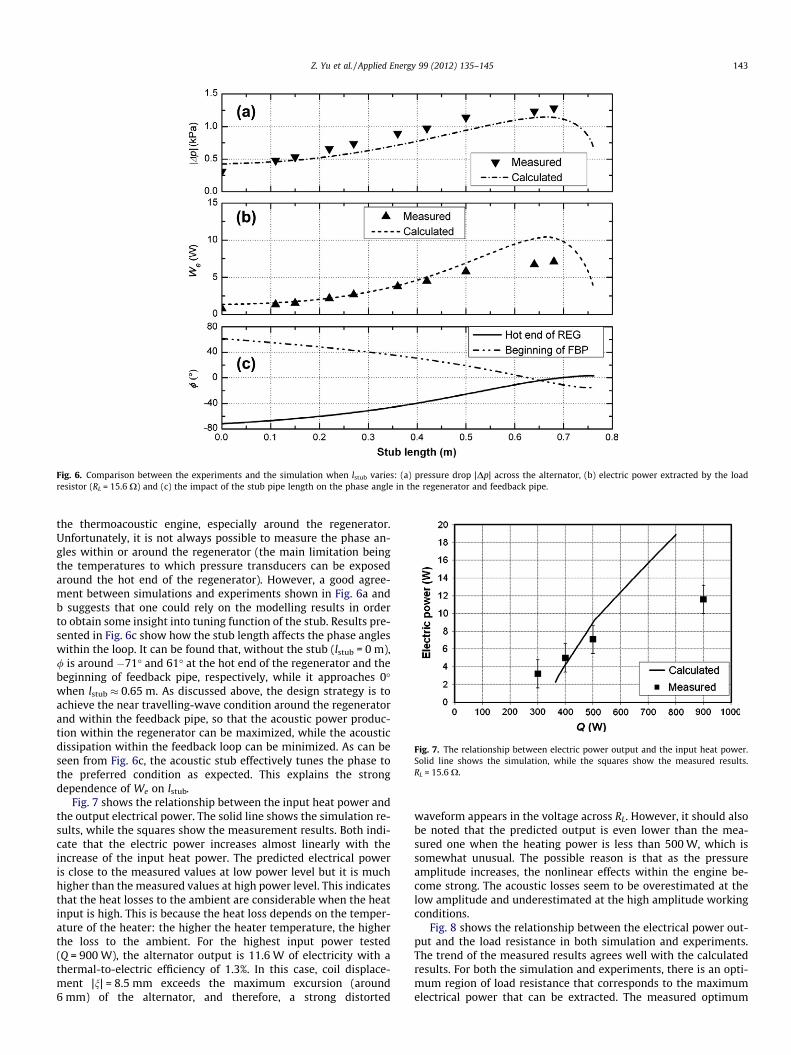
Fig. 6. Comparison between the experiments and the simulation when lstub varies: (a) pressure drop |Dp| across the alternator, (b) electric power extracted by the loadresistor (RL = 15.6 X) and (c) the impact of the stub pipe length on the phase angle in the regenerator and feedback pipe.
Fig. 7. The relationship between electric power output and the input heat power.Solid line shows the simulation, while the squares show the measured results.RL = 15.6 X.
Z. Yu et al. / Applied Energy 99 (2012) 135–145 143
the thermoacoustic engine, especially around the regenerator.Unfortunately, it is not always possible to measure the phase an-gles within or around the regenerator (the main limitation beingthe temperatures to which pressure transducers can be exposedaround the hot end of the regenerator). However, a good agree-ment between simulations and experiments shown in Fig. 6a andb suggests that one could rely on the modelling results in orderto obtain some insight into tuning function of the stub. Results pre-sented in Fig. 6c show how the stub length affects the phase angleswithin the loop. It can be found that, without the stub (lstub = 0 m),/ is around �71� and 61� at the hot end of the regenerator and thebeginning of feedback pipe, respectively, while it approaches 0�when lstub � 0.65 m. As discussed above, the design strategy is toachieve the near travelling-wave condition around the regeneratorand within the feedback pipe, so that the acoustic power produc-tion within the regenerator can be maximized, while the acousticdissipation within the feedback loop can be minimized. As can beseen from Fig. 6c, the acoustic stub effectively tunes the phase tothe preferred condition as expected. This explains the strongdependence of We on lstub.
Fig. 7 shows the relationship between the input heat power andthe output electrical power. The solid line shows the simulation re-sults, while the squares show the measurement results. Both indi-cate that the electric power increases almost linearly with theincrease of the input heat power. The predicted electrical poweris close to the measured values at low power level but it is muchhigher than the measured values at high power level. This indicatesthat the heat losses to the ambient are considerable when the heatinput is high. This is because the heat loss depends on the temper-ature of the heater: the higher the heater temperature, the higherthe loss to the ambient. For the highest input power tested(Q = 900 W), the alternator output is 11.6 W of electricity with athermal-to-electric efficiency of 1.3%. In this case, coil displace-ment |n| = 8.5 mm exceeds the maximum excursion (around6 mm) of the alternator, and therefore, a strong distorted
waveform appears in the voltage across RL. However, it should alsobe noted that the predicted output is even lower than the mea-sured one when the heating power is less than 500 W, which issomewhat unusual. The possible reason is that as the pressureamplitude increases, the nonlinear effects within the engine be-come strong. The acoustic losses seem to be overestimated at thelow amplitude and underestimated at the high amplitude workingconditions.
Fig. 8 shows the relationship between the electrical power out-put and the load resistance in both simulation and experiments.The trend of the measured results agrees well with the calculatedresults. For both the simulation and experiments, there is an opti-mum region of load resistance that corresponds to the maximumelectrical power that can be extracted. The measured optimum

Fig. 8. Effect of load resistance on the output electric power. The comparisonbetween simulation (solid line) and measured results (triangles).
144 Z. Yu et al. / Applied Energy 99 (2012) 135–145
region of RL agrees with the calculated one. The extracted electricalpower depends on both the coil velocity amplitude |u1| and RL forthe given alternator. For a given |u1|, in order to extract more elec-trical power RL should approach Re. So reducing RL from a very highvalue (for example 45 X in Fig. 8) can increase the extracted elec-trical power. However, according to Eq. (10), as the load resistanceRL decreases further, the equivalent acoustic impedance of thealternator increases quickly, and therefore, the interaction be-tween the alternator and the engine becomes stronger. As a result,the alternator causes a higher pressure drop. However, as the heatinput is fixed, the possible pressure amplitude is also limited. Con-sequently, this high impedance dramatically decreases |u1|. There-fore, the acoustic power flow through the alternator diaphragm,which is feeding back to the cold end of the regenerator, also de-creases. Therefore, less net acoustic power can be produced inthe regenerator. The results in Fig. 8 show how to balance theacoustic power extraction and feedback in the proposed thermoa-coustic generator.
Finally, based on this research, some general guidelines fordeveloping ultra-complaint alternators and the related inexpen-sive thermoacoustic electricity generators can be drawn. In themost general sense, an ideal alternator of the kind described in thispaper should cause minimum changes to the engine acoustic field,while also having a high transduction efficiency. Firstly, the alter-nator acoustic impedance should be designed as small as possibleto reduce the ‘‘disruption’’ to the acoustic field in the thermoacou-stic engine compared to the case with no alternator. Therefore, thegenerator should operate at the alternator’s resonance frequencyto eliminate the reactive part of the alternator impedance. How-ever, it is not always possible to match the frequency exactly be-cause the frequency will rise slightly as the gas in the engine isheated up during its operation. In this case, according to Eq. (11),the moving mass and stiffness should be as small as possible toavoid a large reactive impedance when the operating frequencyis a few Hz off the alternator resonance. The mechanical resistance(or mechanical quality factor) should be kept low (or high) to min-imize the acoustic loss. Secondly, the electrical resistance of thealternator should be designed small to reduce the electric powerloss due to Joule heating within the coil, while the Bl factor shouldbe high to achieve high conversion efficiency. There is a trade-offbetween these two requirements for deciding the coil length.Thirdly, the area of the diaphragm should be similar to that ofthe acoustic duct where it is installed to avoid sudden changes ofthe cross-sectional area which cause undesirable acoustic losses.Fourthly, the excursion of the coil should be large to ensure a highelectric power production.
Furthermore, the cone-shaped diaphragm of the alternator usedin the current research introduces an unwanted volume (acousticcompliance) to the thermoacoustic engine, which complicates theimpedance matching for the whole system. Such cone should ide-ally be replaced by a flat plate in the practical design of future ul-tra-compliant alternators. In addition, as the alternator is installedwithin the loop, the front of the diaphragm receives the acousticpower, while its back needs to radiate the remaining acousticpower to the feedback pipe. From this point of view, the testedalternator is clearly asymmetrical. The cage and magnet at the backof this alternator alters the acoustic field and causes considerableacoustic losses. In a practical design, it would be better to have flatdiaphragms of the same size at the two sides of the alternator, sothat the conventional cage and magnet can be hidden in betweentwo diaphragms, and therefore, nearly symmetric acoustic inter-faces can be obtained at the two sides of the alternator (e.g. theHalbach array linear alternator [20]). Finally, the glass fibre dia-phragm of the tested alternator handled successfully a pressuredifference more than 1000 Pa. However, the maximum pressuredrop that this kind of diaphragm can handle is still unknown. Forhigh pressure and high power applications, the required pressureamplitude is much higher, and this would be a challenge for con-ventional diaphragms used in loudspeakers. For example in a30 bar helium system, with a relative acoustic pressure amplitudeof 10%, the required pressure drop across the diaphragm would bearound 30–40 kPa according to the estimates based on results ofthis work. Clearly, this is too large for the conventional paper orpolymer diaphragm. Therefore, one should use other stronger,but light materials such as carbon fibre or aluminium to makethe diaphragm. For example, Tijani et al. replaced the paper coneof a commercial moving-coil loudspeaker with 0.6 mm thick alu-minium plate, and applied it as an acoustic driver for their ther-moacoustic cooler. The modified loudspeaker could produce 2.1%acoustic pressure amplitude in a 10 bar helium system. [18] There-fore, it seems that it would be feasible to develop ultra-compliantalternators based on the audio loudspeaker technology for highpower application, although some practical challenges would stillneed to be addressed.
6. Conclusion
This paper proposes a novel concept of a travelling wave ther-moacoustic generator. The novelty lies in three aspects: the utiliza-tion of the ultra-complaint alternator, the stub used for phase andimpedance tuning, and the CHX designed to have a phase shiftinginertance. The tuning stub effectively corrects the acoustic fieldwithin the looped-tube engine altered by the installation of thealternator. It is particularly useful for the practical design of suchgenerators because of the unavoidable manufacturing uncertain-ties and fluctuating electrical loads. Based on the proposed con-cept, a simple prototype produced useable amount of electricity.The measurement results have verified both the simplified and de-tailed design models. Theoretically, this type of generator canachieve much higher efficiencies when using a high pressure he-lium as the working gas and an improved alternator. Because theultra-complaint alternators could in principle be developed utiliz-ing a typical technology used in the loudspeaker manufacture, theresults shown in this paper illustrate the potential of developinginexpensive electricity generators based on thermoacoustic tech-nology. Some design guidelines and strategies have also been pro-posed for developing future ultra-compliant alternators.
Acknowledgments
The authors would like to acknowledge the support from EPSRC(UK) under Grant EP/E044379/2.

Z. Yu et al. / Applied Energy 99 (2012) 135–145 145
References
[1] Swift GW. Analysis and performance of a large thermoacoustic engine. J AcoustSoc Am 1992;92:1551–63.
[2] Yazaki T, Iwata A, Maekawa T, Tominaga A. Traveling wave thermoacousticengin in a looped tube. Phys Rev Lett 1998;81:3128–31.
[3] Backhaus S, Swift GW. A thermoacoustic-Stirling heat engine: detailed study. JAcoust Soc Am 2000;107:3148–66.
[4] Gardner DL, Swift GW. A cascade thermoacoustic engine. J Acoust Soc Am2003;114(4):1906–19.
[5] de Blok CM. Low operating temperature integral thermoacoustic devices forsolar cooling and waste heat recovery. Acoustics’08, Paris; June 29–July 4,2008.
[6] Ceperley PH. A pistonless Stirling engine – the traveling wave heat engine. JAcoust Soc Am 1979;66:1508–13.
[7] Tijani MEH, Spoelstra S. A high performance thermoacoustic engine. J ApplPhys 2011;110:093519.
[8] De Blok K. Novel 4-stage traveling wave thermoacoustic power generator. In:Proceedings of ASME 2010 3rd joint US-European fluids engineering summermeeting and 8th international conference on nanochannels, microchannelsand minichannels, FEDSM2010-ICNMM2010, Montreal, Canada; August 2–4,2010.
[9] Backhaus S, Tward E, Petach M. Travelling-wave thermoacoustic electricgenerator. Appl Phys Lett 2004;85(6):1085–7.
[10] Wu ZH, Man M, Luo EC, et al. Experimental investigation of a 500 W traveling-wave thermoacoustic electricity generator. Chinese Sci Bull 2011;56:1975–7.
[11] Jensen C, Raspet R. Thermoacoustic power conversion using a piezoelectrictransducer. J Acoust Soc Am 2010;128:98–103.
[12] Jordan EJ. Loudspeakers. London: Focal Press; 1963.[13] Yu Z, Saechan P, Jaworski AJ. A method of characterising performance of audio
loudspeakers for linear alternator applications in low-cost thermoacousticelectricity generators. Appl Acoust 2011;72(5):260–7.
[14] Yu Z, Jaworski AJ. Impact of acoustic impedance and flow resistance on thepower output capacity of the regenerators in travelling-wave thermoacousticengines. Energy Convers Manage 2010;51:350–9.
[15] Gedeon D. DC gas flows in Stirling and pulse tube refrigerators. In: Ross RG,editor. New York: Cryocoolers 9, Plenum; 1997. p. 385–92.
[16] Swift GW. Thermoacoustics: a unifying perspective for some engines andrefrigerators. Sewickley, PA: Acoustical Society of America, Publications; 2002.
[17] Kinsler LE. Fundamentals of acoustics. 4th ed. John Wiley & Sons; 2000.[18] Tijani MEH, Zeegers JCH, de Waele ATAM. Construction and performance of a
thermoacoustic refrigerator. Cryogenics 2002;42(1):59–66.[19] Ward WC, Swift GW. Design environment for low-amplitude thermoacoustic
engines. J Acoust Soc Am 1994;95:3671–2.[20] Saha CR, Riley PH, Paul J, Yu Z, Jaworski AJ, Johnson CM. Halbach array linear
alternator for thermo-acoustic engine. Sensor Actuator A: Phys2012;178:179–87. http://dx.doi.org/10.1016/j.sna.2012.01.042.