copyright © 2009 pearson education, inc. chapter 29: magnetic fields
TRANSCRIPT

Copyright © 2009 Pearson Education, Inc.
Chapter 29: Magnetic Fields

Copyright © 2009 Pearson Education, Inc.
• Magnets & Magnetic Fields B Fields• Electric Currents Produce B Fields• Force on an Electric Current in a B Field;
Definition of B• Force on an Electric Charge Moving in a B Field• Torque on a Current Loop; Magnetic Dipole Moment μ
• Applications: Motors, Loudspeakers, Galvanometers• Discovery & Properties of the Electron• The Hall Effect• Mass Spectrometer
Chapter 29 Outline

Copyright © 2009 Pearson Education, Inc.
Brief History of Magnetism13th Century BC
– Chinese used a compass• Uses a magnetic needle• Probably an invention of Arabic or Indian origin
800 BC– Greeks
• Discovered magnetite (Fe3O4) attracts pieces of iron
1269– Pierre de Maricourt found that the direction of a needle
near a spherical natural magnet formed lines that encircled the sphere.
– The lines also passed through two points diametrically opposed to each other.
– He called the points poles

Copyright © 2009 Pearson Education, Inc.
1600– William Gilbert
• Expanded experiments with magnetism to a variety of materials• Suggested the Earth itself was a large permanent magnet
1750– Experimenters showed that magnetic poles exert attractive
or repulsive forces on each other.1819
– Found that an electric current deflected a compass needle1820’s
– Faraday and Henry• Further connections between electricity and magnetism• A changing magnetic field creates an electric field.
James Clerk Maxwell• A changing electric field produces a magnetic field.

Copyright © 2009 Pearson Education, Inc.
Hans Christian Oersted1777 – 1851
Discovered a relationship between electricity & magnetism.•Found that an electric current in awire will deflect a compass needle.
First to find evidence of the connection between electric &
magnetic phenomena.
•The first to prepare pure Aluminum.

Copyright © 2009 Pearson Education, Inc.
Magnets & Magnetic FieldsEvery magnet, regardlessof its shape, has two endscalled “Poles”. They arecalled the l “North (N) Pole” and the l “South (S) Pole” (which will be discussed soon!)The poles exert forces on oneAnother:
Like poles repel.Unlike poles attract.
Copyright © 2009 Pearson Education, Inc.
•The poles received their names due to the way amagnet behaves in the Earth’s magnetic field.•If a bar magnet is suspended so that it can move freely, itwill rotate.
– The North pole of a magnet points toward the Earth’s North magnetic pole.
• This means the Earth’s North magnetic pole is actually a magnetic South pole.
• Similarly, the Earth’s South magnetic pole is actually a magnetic North pole.
•The force between two poles varies as the inverse square ofthe distance between them.A single magnetic pole has never been isolated.In other words, magnetic poles are always found in pairs.– All attempts so far to detect an isolated magnetic pole (a magnetic
monopole) has been unsuccessful.• No matter how many times a permanent magnetic is cut in two, each
piece always has a north and south pole.
Copyright © 2009 Pearson Education, Inc.
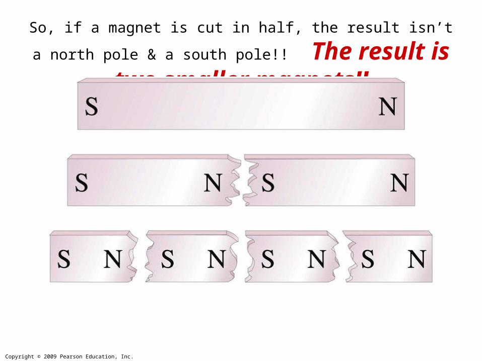
So, if a magnet is cut in half, the result isn’t a north pole & a south pole!!
The result is two smaller magnets!!

Copyright © 2009 Pearson Education, Inc.
Magnetic Fields•Reminder: An electric field surrounds any electriccharge. Similarly,
The region of space surrounding any MOVING electric charge also contains a magnetic field.
•A magnetic field also surrounds a magnetic substancemaking up a permanent magnet. A magnetic field is avector quantity. It is symbolized by B
•The direction of a magnetic field is given by thedirection the North pole of a compass needle points inthat location.•Magnetic field lines can be used to show how thefield lines, as traced out by a compass, would look.

Copyright © 2009 Pearson Education, Inc.
Magnetic fields can be visualized using
Magnetic Field Lines,which are always closed loops.

Copyright © 2009 Pearson Education, Inc.
Magnetic Field Lines, Bar Magnet•A compass can be used to tracethe field lines.•The lines outside the magnet point from the North pole to theSouth pole.•Iron filings can also be used toshow the pattern of the magneticfield lines.•The direction of the magneticfield is the direction a north polewould point.

Copyright © 2009 Pearson Education, Inc.
Magnetic Field Lines
Like Poles
OppositePoles

Copyright © 2009 Pearson Education, Inc.
Earth’s Magnetic Fieldis similar to that of a bar magnet.
It is very small:
BEarth 50 μTIt depends on location & altitude.
It is also slowlychanging with time!
Note!!!The Earth’s magnetic
“North Pole” is really a South Magnetic Pole, because the North poles of magnets are attracted to it.

Copyright © 2009 Pearson Education, Inc.
•The source of the Earth’s magnetic field is likelyconvection currents in the Earth’s core.•There is strong evidence that the magnitude of a planet’smagnetic field is related to its rate of rotation.•The direction of the Earth’s magnetic field reversesPeriodically (over thousands of years!).
Earth’s Magnetic Field

Copyright © 2009 Pearson Education, Inc.
A Uniform Magnetic Fieldis constant in magnitude & direction.
The magnetic field B between these two wide poles is nearly uniform.

Copyright © 2009 Pearson Education, Inc.
Experiments show that An Electric Current Produces a Magnetic Field.
The direction of the field is given by a RIGHT-HAND RULE.
Electric Currents Produce Magnetic Fields

Copyright © 2009 Pearson Education, Inc.
The Magnetic Field Due to a Current Loop.
The direction is given by a Right-Hand Rule.

Copyright © 2009 Pearson Education, Inc.
A magnet exerts a force F on a current-carrying wire. The DIRECTION of F is given by a
Right-Hand Rule.
Force on a Current in a Magnetic Field
Definition of B
Copyright © 2009 Pearson Education, Inc.
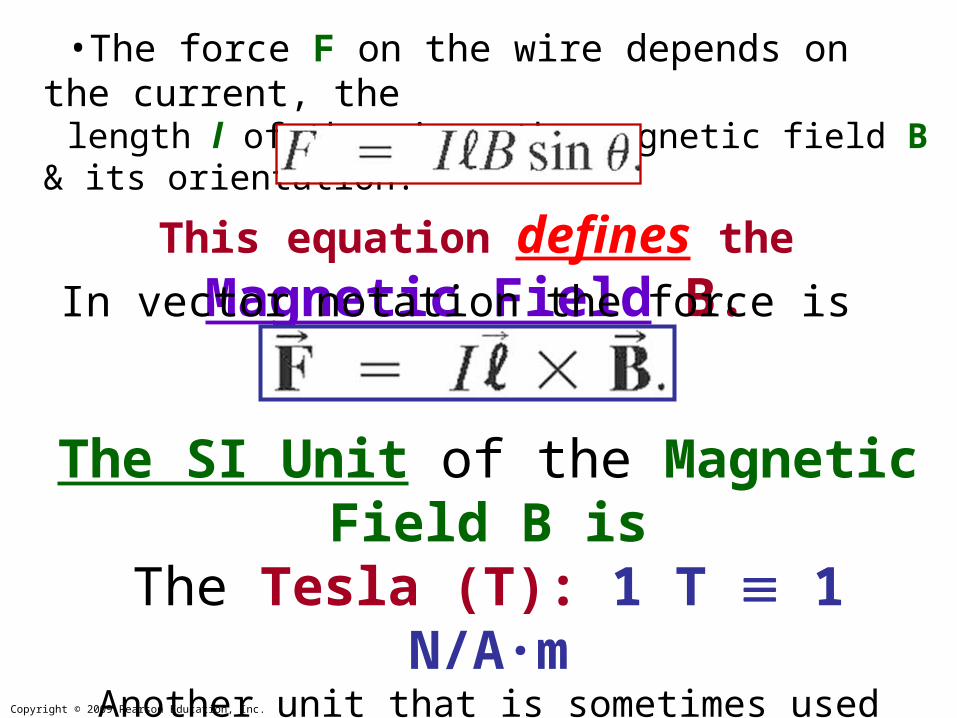
The SI Unit of the Magnetic Field B isThe Tesla (T): 1 T 1 N/A·m
Another unit that is sometimes used (from the cgs system) is
The Gauss (G): 1 G = 10-4 T
•The force F on the wire depends on the current, thelength l of the wire, the magnetic field B & its orientation:
This equation defines the Magnetic Field B.In vector notation the force is given by

Copyright © 2009 Pearson Education, Inc.
•A wire carrying a currentI = 30 A has lengthl = 12 cm between the polefaces of a magnet at angle θ = 60° as shown. Themagnetic field is approximatelyuniform & is B = 0.90 T. •Calculate the magnitude of the force F on the wire.
Example Magnetic Force on a Current Carrying Wire

Copyright © 2009 Pearson Education, Inc.
•A wire carrying a currentI = 30 A has lengthl = 12 cm between the polefaces of a magnet at angle θ = 60° as shown. Themagnetic field is approximatelyuniform & is B = 0.90 T. •Calculate the magnitude of the force F on the wire.
Solution: Use
Example Magnetic Force on a Current Carrying Wire
Solve & get:F = 2.8 N

Copyright © 2009 Pearson Education, Inc.
A rectangular wire loop hangs vertically. A magnetic field B is directed horizontally, perpendicular to the wire, & points out of the page. B is uniform along the horizontal portion of wire (l = 10.0 cm) which is near the center of the gap of the magnet producing B. The top portion of the loop is free of the field. The loop hangs from a balance which measures a downward magnetic force (in addition to the gravitational force) F = 3.48 10-2 N when the wire carries a current I = 0.245 A. Calculate B.
Example: Measuring a Magnetic Field

Copyright © 2009 Pearson Education, Inc.
A rectangular wire loop hangs vertically. A magnetic field B is directed horizontally, perpendicular to the wire, & points out of the page. B is uniform along the horizontal portion of wire (l = 10.0 cm) which is near the center of the gap of the magnet producing B. The top portion of the loop is free of the field. The loop hangs from a balance which measures a downward magnetic force (in addition to the gravitational force) F = 3.48 10-2 N when the wire carries a current I = 0.245
A. Calculate B. Solution: Use
Example: Measuring a Magnetic Field
Solve & get:B = 1.42 T

Copyright © 2009 Pearson Education, Inc.
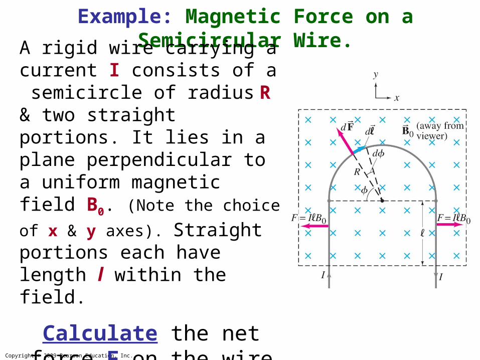
Example: Magnetic Force on a Semicircular Wire.
A rigid wire carrying a current I consists of a semicircle of radius R & two straight portions. It lies in a plane perpendicular to a uniform magnetic field B0. (Note the choice of
x & y axes). Straight portions each have length l within the field.
Calculate the net force F on the wire due to B0.
Copyright © 2009 Pearson Education, Inc.
Example: Magnetic Force on a Semicircular Wire.
A rigid wire carrying a current I consists of a semicircle of radius R & two straight portions. It lies in a plane perpendicular to a uniform magnetic field B0. (Note the choice of
x & y axes). Straight portions each have length l within the field.
Calculate the net force F on the wire due to B0.
Solution gives:
F = 2IB0R