copy - digital library/67531/metadc54111/m2/1/high... · wing spars which are subjected to combined...
TRANSCRIPT

NATIOKAL ADVISORY COMMITTEE I?OR AEROmMJTICS
i5
.
METAL-TRUSS lfIYG SPARS
By Andrew E. Swickard
FILE COPY
.
ITashingt mJuly , 1931
?.’.: 5., -. :“: ----; ‘&
NiTIONAL ADVISORY COMMITTEE,FOR AERON+U~ICS
. . .
.,
Sinceuse in theal methods
?ECHITICAL NOT~ ~0. 383 .. .. ..—
IIETAL-TRUSS WING SpA.RS*
BT Andrew E. .Swickard
INTRODUCTION
metal-truss wing spars are comifig into generalaizplane industry, it is necessary that ration-for their design be developed.
The purpose of the “stud~,,recorded ”in this thesis wasto develop improvements in the current methods for thecalculation of the loads in the members of metal-trusswing spars which are subjected to combined bending andcompression.
bIf there were no axial load in the metal-truss spar,
its design would be very simple, because ordinary trussanalysis methods could be used to determine the loads in,its menbers. How8ver, when axial compression is actingtogether with a side’ load, the loads in the aenbers of thetruss spar are functions of the deflections of the spar,since the con’bination of these deflections with axial loadproduces additional bending noments and shears. These. ad-ditional bending moments and shears nay be ref,erred to asthe secondary bending monents and secondary shears. It isnecessary, then, to calculate the effect of the deflectionsof the pan’el p’oints of a tru-ss spar to determine the trueloa”ds”in its monbers.’, : ,-
The present design rule of the Department of Commercespecifies that equations** for the calculating of bendingmoments and shears on uniform beams subjected to combinedbending and compression shall be used for calculating thebending moments” arid shears on,metal-truss wing spars. Inorder to use these equations, which will ba referred to
——..-—- ——.-‘~hesis submitted fn partial i%l~~lment of %herequire-m“ents for the degree of Engineer in Mechanical Engineer-ing Aeronautics, Stanford University, 1930.
●.*
**Aeronautics Bulletia No; ‘7-A,”~e-c* 70 (~) ‘“~4).
:
2 N.A. C.A. Technical ~ot~’~o~ 383-”’- “ ““
. .below as the Precise Formulas’, * &’”value of effective mo-ment of inertia is needed.
Once these befi~ifig”moments and shears have been de-termined, the loaas in the various truss members can Yecalculated by the use of ordinary truss analysis methods.
The effective moment of inertia of a metal-truss wingspar is something which is not as easily determined as themoment of inertia of an ordinary wooden spar. A.t first,one might erroneously believe that the moment of inertiaat any section of-a truss spar is ‘th8 moment of inertia ofthe areas of the two chord members about the centroid ofthese areas. In the following discussion, this moment ofinertia will be called the ‘lchord moment of inertia.’! Thechard m~rnent of inertia at any section would be the truemoment of inertia if the web members were of infinite areaand did not deform under load. The fundamental beam equa-
tion, Md2
= EI -# upon which all beam equations are
based, was derived under the assumption that the shear de-formation was so small that it oould he neglected. Thisassumption of negligible deformation, resulting from shear,does not really fit even the case of ordinary wooden beams;consequently the value of 11EII is arbitrarily reduced acertain small percentage when the beam equations are beingused for that material. With metal trusses, the shear iscarried by the web members instead of by a continuous web;consequently the web deformation is so great that the de-flection resulting from this deformation cannot be neglect-ed. This deflection will he referred to below as the l~webdeflection, ‘1 As a result, the value of a chord moment ofinertia must be decreased to allow for the decreased stiff-ness which is caused by the deformation of the web members.The portion of the truss spar deflection which resultsfrom the deformation of the chord members will be referredto as the ‘Ichord deflection.11
The Department of Commerce rule specifies that themonent of inertia to be used in the Precise Formulas shallbe determined by backfiguring from deflections which re-sult when the truss spar is subjected to side load. Thetruss spar deflections may be calculated by any convenient
.,).”
—..---—-.—-—- -. ———---—— ------‘i’by Niles and Newell.‘Fee Chapter,XI .“Airplane Structures ,
Y....-.
.—
.—
—
--.,
—
i .,
1,
~;
—
—
.-
.—
—
-—
4“
%-
N.A.C,A. Technical. Note No. 383:...
deflection nethod,* or nay be experimentally
3
determinedfrom full-scale tests. AssWing-the truss spar to be anordinary lean, a value of effective moment of inertia isbackfigured fron the appropriate bean deflection equationby a substitution of the previously determined’deflectionvalues’.
One can readily see that this backfigured effectivenonent of inertia cannot be greatly in error. However,thti entire backfiguring process is so nochanical that thedesigner does not see the theoretical considerations whichara automatically included in that process. In this the- “sis, a direct method of calculating the effective momentof inertia of a “netal-truss wing spar” is developed.. IThis“direct nethod is built up from consideration of the acti,onsof the individual truss aenbers; consequently the designeracquires a nuch better understanding of the quantitieswhich affect the effective noment of inertia than he wouldby using the backfiguring method.
It was originally thought that the effective nonentof inertia of a uetal-truss wing spar might be determineddirectly fron the geo~etrical properties of the chord andweb nenbers. l?urther study, however, proved that the ra-tios of the strains of the web nbnbers to the strains ofthe chord nenbers nust be known in addition to the geo-metrical properties of the truss spai to deternine thecorrect value for’the effective .nonent of tnertia. Sincethese ratios are fupctions of the ezternal loading, it isnecessary to know the type of load to which the truss spar .is to be subjected, before the effective monent of inertiacan be calculated.
The naterial of this thesis is divided into threeparts: The derivations of the theoretical concepts aregiven first. Th,e practical applications of the theoryfollow. Finally, in the form of an appendix, the effectivenonent of ~gertia of an actual netal-truss wing spar iscalculated. This wing spar was built and tested-for de-flection under conbined bending and conpressi.on by theBooing Airplane Conpany. The calculated value of the ef-fective noment of inertia is checked against the test data,and conclusions are drawn regarding the accuracy of thecalculated value of effective monent of inertia.
—— ——— —_____ -—-- — .—*See page 311 llAirplane Structures 11%y Niles and Newell.
4 fi.A, 04”.4,Technical Not’e’No; 393:
,,, .
@ORETICAL Dl!RIVATIONS
The purposo of the following der~vations is the ra-t“ional determinati~n of ‘chk’sffectivo moment of inertiaof a zcetal-truss wing spar.
?
Tf there is no shear deformation, the beam equation
M= XI !=, or ,1 = -d.—dx 2
is accurate. With metal-truss~ gi
. _.
,.~x2 ,
wing spars, the shear” deflection resulting from the strainof the web members is so, large that the o“rdinary bea”m equa-tion does not hold. l?ha beam equation may be made to applyif the value of 1, the chord moment of inertia, is prop-erly reduced to allow for shear deformation. In other .wor~s , the deflection of the spar produced by web mornber
deformation increases &, and consequently reduces theax2
effcctivo value of ‘I. Consequently, thQ first step in the.
solution of the problem is to derive an equation which givestne increi~ents of web deflection between adjacent panelpoints .of the truss spar in terms of the deforr.~at%on of the
.
me-o nenhers. Next, the relation between the web doflecti6nincrenent’s betmeen’panel points and the resulting chango
in ~ must Ye doternined. Then an accurate nethod ofdx2
calculating the decrease of’ effective ~ommt cf inertia
&% nust be developed.due to the changes i-n Since theax 2
mol~ent of inertia of an ordinary truss spar varies fronoae panel to the next, it is necessary to work out a neansof weighting the effect of the moments of inertia in theVarious panels upon the stiffne,es o“f the spar as a whole.
—. —
Finally a method of computing the affective moment of in-ertia of the entire truss spar must be developed from thereduction of chord moment of inertia in each panel, andfrom the relative importance of th.c moments of inartia intho various panels.
The theoretical derivations %elow include three sec-tions which have only an indirect bea?ing on the main de-velopments of the thesis. The first of these sectionscovers tho derivation of an equation for tl~e increment of
2
deflcctiGn between adjacent panel points produced hy the—

,,, .
N.A. C.~. Technical Note No. ”383 5
. .
deformation, or strain, of. th{.‘chord members. The secondis the derivation of rules. f~r calculating the total de-flections of the panel poi~ts of a truss directly from theweb and chord increments of deflection between panel points.This method of calculating deflections is very simple anddirect, consequently it can often be used instead of thestandard deflection methods. Its main value, however, isthat it is developed fr,on simple geometrical relations inthe truss and thus gives one a very concrete concept ofthe action which takes place when a truss deflects underload. The third of the three, sections is one which givesan exact method of calculating the total bending momentsand shears to which a metal truss wing spar is subjectedwhen acted upon by axial and side loads. It is an ex-.trenely lengthy method, and is only of value in checkingthe approximate method of calculating the effective momentof inertia. This exact method is pot a development of thethesis; it has been known to structural engineers for sometime.
(I) INCREMENT OF TRUSS DEFLECTION
“BETWEEN ADJACENT PANEL POINTS
PRODUCED BY THE STRAIN OF THE WEB MEMB3RS OF THE PANXL
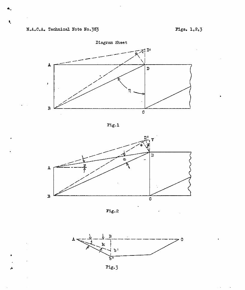
Parallel chord trusses.- Refer to Figure 1 of the——diagr-~heets.. A3CD ~~esents the center lines of themembers of one panel of a truss. When the truss is sub-jected to load, web member BD is strained; consequentlypanel point D deflects an amount D_D! above panelpoint A. The object of the following derivation is todeternine the relation %etween the deflection D-D! , andthe strain in we% menber BD.
.. .
There aro three assumptions on which the followingderivation is based:
1) The deflections of the panel points of the trussare so small that the arc traced by one end of a trussmer~ber when the member is considered to rotate &bout thepin -at its other end appr~xina,tes a straight line. . .:,
.-2) The nerlbers of the truss are assumed to b’e con- :
netted by ~ins.,.

—,
-.? :43 N.A.C.A. Technical Note No. 383 —
.,
3) Si:ce the principloof superposition is implied,when’ one speaksof the total deflections as being the sum
---
of “chord; deflections and web deflections, it is logical .—.
to calculate the deflections produced by the strain of theweb nembers using the assufiption that the chord nembersare unstrained.
Web nenber BD is strained an anount represented. by —-.,eD1. This strain allows member AD to rotate about A,and take up a new position A~l,
ZDeDt, Z.eDB, and LDD~A can be considered to be —right angles, since the radius of an arc is perpendicularto the tangent at the point of intersection of the radius
—=,
and the arc.
A oDD I = L_(90°-q), since the sides of the angles aro—mutually perpendicular.
sin (.LeDD!) = +.
Substituting the value of ZeDDl:
sin (900-~) = SD+; or eD 1Cos ~ = —DD I
e~ 1DD1 =Cos ~“
Since eDl = the strain of the webthe’i,ncrernent of web deflection,
deflection increment =
member, and DD I
,
. .
is
(1)Cos q
NonParallel chord trusses.-..—.——-—---— Refer to Figure. 2 of thediagram sheet. ‘AISCD rem~esents the members of tine”panel—of a nonparallel chord truss. The line CDV repres&ts
.-
the direction in which the deflection of the panel pointD is to be calculated.
.—
When the diagonal web member BD is strained, chordmember AD is allowed. to rotate about A, and takes up . .
the position AD1. The point D traces the arc DD I
when AD rotates about A. Member BD rotates about Bs~.
and occupies the position BDI, De is an arc drawn with —
&
. .
N.A.C.A. Technical Note No. 383 7
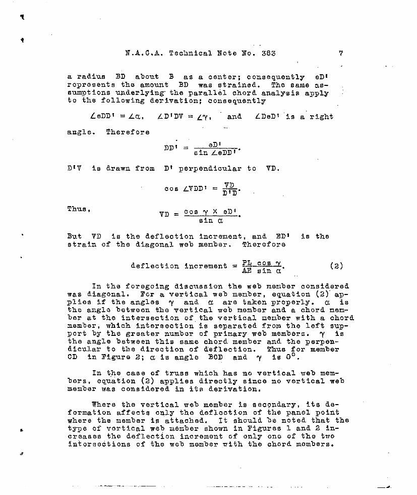
a radius 3D about B as a center; consequently ~~ 1represents the amount BD was strained. The same as-sumptions underlying” the parallel chord analysis apply :to the following derivation; consequentl~
ZeDDl =Za, ~~lD~ =~ry, and
angle. Therefore...
. .DDI = _ eD !
sin LeD~*
D~V is drawn from Dt perpendicular
cos LViID~ = ~.DtD
Thus ,VD = !?.OsY X eD~m
sin a
LDeD! ‘is a right
to VD.
But VD is the deflection increnent, and ED! is thestrain of the diagonal web menber. Therefore
(21
In the foregoing discussion the web menber consideredwas dtagonal, 3’Gr a vertical web menber, equation (2)” ap-plies if the angles y and a are taken properly. a isthe angle between the vertical web member and a chord nen-ber at the intersection of,the vertical nember with a chordmember, which intersection is separated from the left sup-port by the greater number of primary web members. y isthe angle between this same chord member and the perpen-dicular to the direction of deflection. Thus for memberCD in Figure 2; a is angle BCD and y is OO.
In the case of truss which has no vertical web mem-bers, equation (2) applies directly since no vertical webmember was considered in its derivation.
Where the vertt.cal web member is secondary, its de-formation affects only the deflection of the panel pointwhere the member is attached. It should he noted that thetype of vertical web member shown in Figures 1 and 2 in-creases the deflection increment of only ono of the twointersections of the web member vith the chord members.

8 N.A, C.-k. Technical Hote Ho. 383
.,
Thus in Figure 2, it can be roedily seen that the strainof member ‘DC increases th~ deflection incrment botwoonpanel points B an~.. C, but does not affect the deflec-tion increment between panel points A and D.
(II ) CORRECTION OF CHORD MOMENT 03’ INERTIA
FOR WEB DEFLECTION
If the web members of a truss spar were not strained,the truss spar could be consldored to he an ordinary beanwhich had values of moments of inertia equal to tho corre-sponding values of chord monents of i:lertia.*
The equatioi~ which is the basis of boa~.1theory is
M= EI ~,
(3)
By exatiirling equation (“3), it is apparent that any
modification of ~ represents a ‘change of monent of i.~-~x2
ertla. At a?ly section of tho truss spar, tho strain’ of
the web members changes & and consequently, the ef-dx2
fective moment’ of icertia.. The following derivatio:l is a
calculation of the increnent of ~fi produced by thedxe
Strain of th~ web nombors. The chaago of moaont of inertia.
roprosentod by this increuent of <~ is then calculateddx z
fromequation (3).
Thoro are sovoral conceptfi~,npo: wl+ich tho followincderivation is based, al~d they will bc stated beforo thodo~:.ivatlGn is given.
—
—
—
-3
—
.—
,.,—--- .--------------- .--—. -—-—..——-—---.---.—--—.---—.----—-.—*Seo page 311 llA~rplS,i10Structurosl’ by Nilos “and Uowoll.
‘t
7
.
.
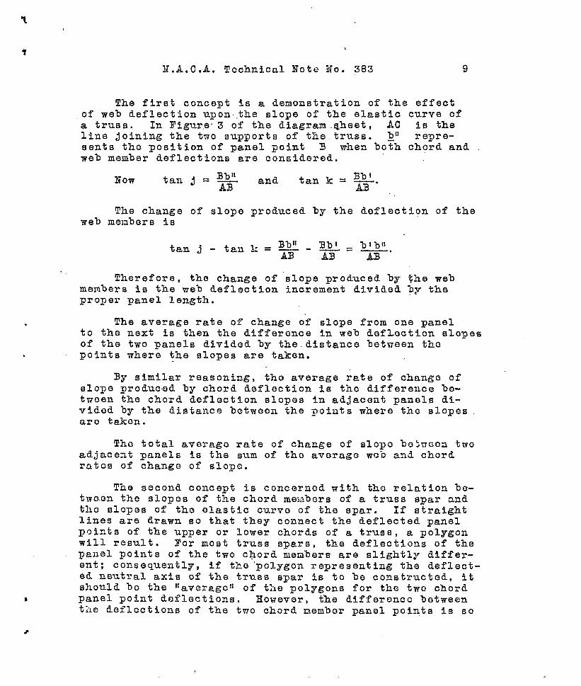
The first concept is a demonstration of the effectof web deflection upon.,the slope of the elastic curve ofa truss. In I?igur.e3 of the diagram.qheet, AC is theline joining the two supports of the.truss. ~!1
sents tho position of panel point 3 when bo~h c~%~eandweb member deflections are considered.
Now tan j = ‘~ and tan k = ~.
The change of slope produced by the deflection of theweb menbers is
Therefore, the change of slope produced by $he webmembers is the web deflection increment divided ‘py theproper panel length.
The average rate of change of slope from one panelto the next is then the difference in web defl.ecti.on slopesof the two panels divided by the. distance between thepoints where the slopes are taken.
By similar reasoning, tho average rate of change ofslope produced by chord deflection is the difference be-tvoen the chord deflection slopes in adjacent panels di-vided by the distance betwean the points where the slopesaro taken.
The total avorago rate of change of slopo betwcca twoadjaceat panels is the sum of tho average wcb anti chordrates of chango of slope.
The second concept is concernod with tho relation bo-tmaon the slopos of the chord mei~bcrs of a truss spar andthe slopes of the elastic curve of the spar. If straightlines are drawn so that they connect the deflected panelpoints of the upper or lower chords of a truss, a polygonwill result. For most truss spars, the deflections of thepanel points of the two chord members are slightly differ-ent; consequently, if the “polygon representing the deflect-ed neutral axis of the truss spar is to be constructed, itshould ‘Do the ‘taverago!l of t’he polygons for tb.e two chordpanel point deflections. However, the difference betweenthe deflections of the two chord nembor panel points is so
r
t
10 N.A.C?,A. Technical Not@ No. 383
small that the neutral axis polygon can be coi~6id0r~d tobe the same as the polygon of either chord. If a smoothcurve is Cirann through the” p~ints of either one of thesedofloctic)n POlyg911S, a dc+flection curve tiill result. ‘-Since the slopes of the chords of tho polygons aro verySmall , this smooth curve may be considered the elasticcurvo of tho truss spar.
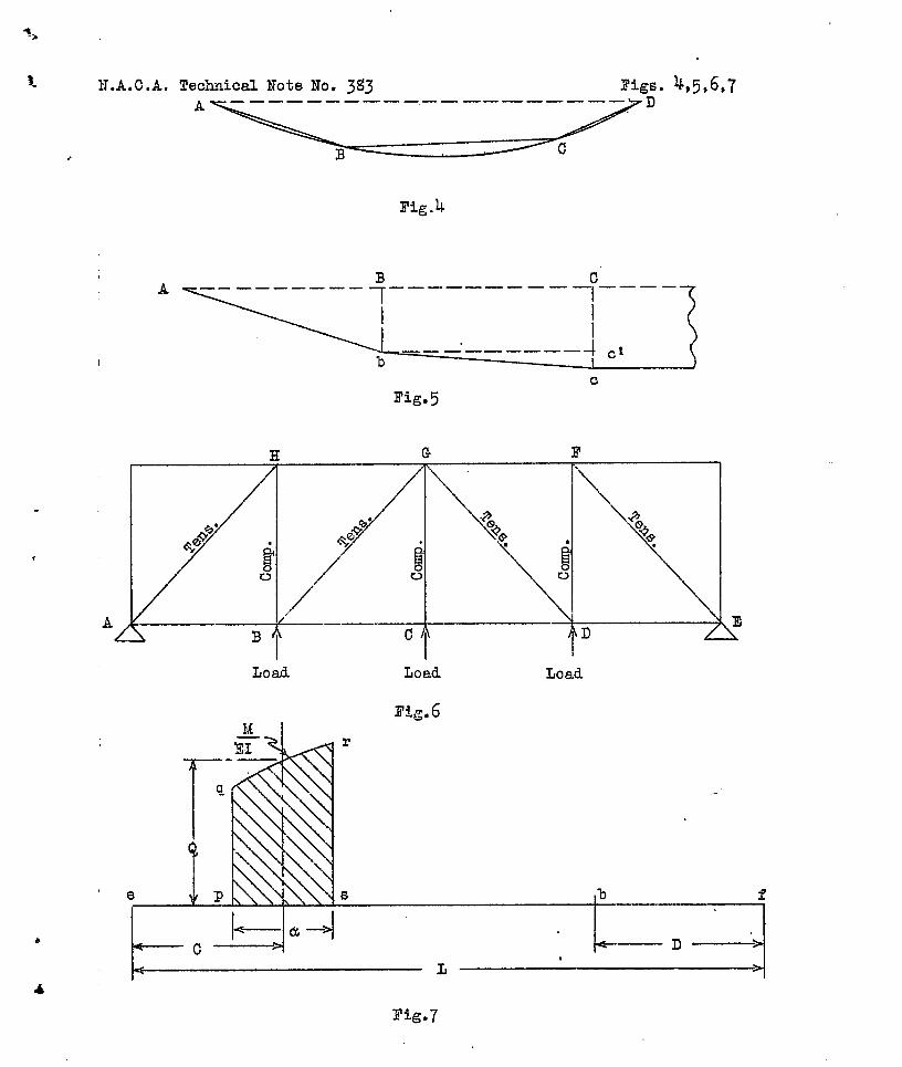
In Figure 4 AD represents the unreflected positionof the lower chord members of a truss. ABCD representsthe deflected position of these nemhers of the tz’uss. Thesmooth curve ABCD is the elastic curve of the truss, andis a flat ‘!parabolali for all ordinary deflections. i{at-urally, the slope of the elastic curve varies at differentpoints alonq the span. For flat parabolas the slope ofthe chord is approximately the slope of the tangent to thecurve at the mid-point of the arc subtended by the chord,!l!hereforo, the slope of a chord member can be con~idorodto bo t~le slope of tho elastic curvo at the middlo of ‘thopanel whore the chord member occurs.
The web rate of change of slope will now be deter-mined from the web de’flect5.on increments of adjacent panelsof a truss. Refer to Figure 5 of the diagram sheet. A.BCrepreseilts the unreflected position of the ripper or lowerchord nenters of a trus’s.‘ Abc represents the posi%inn o~the chord mombor~ vrhen only the strain of tize web membershas produced deflection. B’b is the-”deflection incrementproduced by the strain of the web members iilpanel AB.Clc ~-s the deflection increment produced by the strain “ofthe we% ne!:lbers in panel BC. As was previously demon-strated, the slope of the chGrd member of a panel approxi-mates the slope fif the elastic curve at the mici-point oftke paael. Therefore, the slope of Ab (referred to ABC)is tic slope of the elastic curve at the nid-point of panelA13, Sinilarly, the S1OD6 of chord. nenler bc is the slomeof the elasti~”curve at-the mid-point of panel BC.
*.
BbThe slope of uem’ber Ab = ~ .
The slope of meaber bc =,%$-.
The d’iff’ereuce between the slope at tho nid-poiat.ofpaae~” ‘ BC , and the ‘s16Fe at the nid-poin! of panel A~ i.~t:lcreforc3 ,.
.-——
.-
.-
*
—.
—
‘b

N,A. C.A. Technical Noto No. 383
.
.
Then the average rate of change of slope between thenid-poiats of the two panels is
~cl BbE--XS= (4)fi (average).
*TA3 + ac) ax 2
Assuning that the adjacent panels are of equal length,
11X,11 equation (4) becones ccl - Z3b
X2 “
Siilce the deflection curve is a flat parabola, thisaverage rate of change of slope is the llexactl’rate ofchange Gf slope at a point half way letween the mid-pointsof the two panels. Thus , since the panels are of equal
ccl - Bl)lcnlgth ——— is the exact rate of change of slope atX2
tho panel point B. Th.ereforo, the rate of change of slo~oat a panel point is approximately the difference betweenthe deflection increments of the two adjacent panels di-vided by the sqv.are of the panel length.
62- 61Let —— “De the rate of change of slope at any
x 2
panel point, where 62 - 81 is the difference between the
wet doflecti~n incre~oats of the two adjacent panels.Equation (3) is
. . .
(web) ●
- ,, “i:= (choid)’ E ~B 1(web)
~E ~ (web)
+ x— = ————. —-—1 M
=M 1
+chord —-T–-— “
.

r
.
lz
Since
N,A.C,.4. Technical Note No. 383,,.
(3.X2 x-
1 E(fia - 61)~ + ._-—.—. .-=I Ic
(5)Mx 2
I!quatiori (5) ‘applies to ‘a section of a truss spar oc-curring at a panel point; so M is the moment to whichthe spar is subjected at the panel point, and Ic is thechord moment of inertia at the panel point.
The sign of the deflection increments must be takencorrectly, or the quantity 62 - 81 will be in error.
Movin& along the truss from one support to tho othor, ifthe strain of the web memhor tends to increase the d.ofloc-tion of tho truss, its sign is positive; if tho strain
—-
tends to decrease the deflection of the truss, its oi.gn isnegative. Thus refer to Figure 6.
—,
Considering support A as a datum, the tension inr.errlhers AH and B(I prod.u.ces strains which tend to allowthe truss to deflect upward (with reference to support .3);the strains in members (3D and l?E tend to docrea3e this —upward deflection when one passes fromport E,
Consider equation (5) which is
L = _-.--_-_A_1.+E(&2-8)I Ic Mx 2
suyport A to sup- .-—
. —.—
82 is tile W03 deflection increment of the panel tho
farther from the ‘Idatumllsupport, and 61 is tl.e weh de-
flection increment of the panel the nearer to the IIdatum’1support , —
— —
For parallel..ohords, 8, :1S the Hllm of PL—---, ----—--—— —-—-- -All COS ~values for all the we% ?nem.herswithin th~ panel.
For ncnparallol chords, 6 is the sum of thePL CON” va’lu~s of all of the wcb members within the panel.
a-- ----AI? sin a
...,,.t.
w,.
t
N.A.C.A, “Technical Note No. 383 13
.
.
The web deflection increment produced by a verticalweb member should be divided equally between the two ad-jacent panels. However, it is more conservative to placethe deflection increment entirely in the panelwhich iSthe nearer to the datum support. “
‘III. THE EFFECT OF THE MOMENT OF.INERTIA
OF A PANEL OF A TRUSS SPAR UPON THE DEFLECTION”
03’ ANY PANEL POINT ,OF THE TRUSS
It is oftea desirable to know the effect of the mo-mentrqf iner~”ia of any one panel of a tr’uss spar upon thedeflections of all” of the Fanel l?oints. In the followingderivation”, t“he truss spar will be treated as “a beam withvarying moment of inertia; consequently the ordinary beamtheory methods of calculating deflections can be employed.
For simplicity, it will’ be assuq~.d,’that&31 is zero for
&all panels except the one which contains t.h~ ~x for. ..,....
which the deflection offcct ig being calculated.
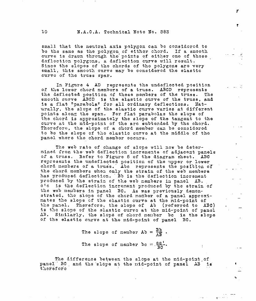
In Figure 7 of the diagram sheet, the deflection ofthe mcint b will be calculated by the method of elasticweights for beams.*
The elastic reaction at f is Qa ~“
The elastic beading moment at b which is numerical-ly equal to the actual deflection, is
Q&CD = .&!&CD=L 331 L
deflection increment. (6)
Since panel ps is any pa]l~l of the truss spar, andb 3s any panel Foiut of tha truss, equation (6) gives theeffect of the monent of inertia Gf any panel of a trussspar upon the.deflection of any panel point.
,.... ,.. ,,.
.’-—. —-—.— , ———.-
%age”303 ‘llAirplaQe” st&uctUre’S ‘ll;b~~fi;~-and Newell.

.
14 I?,A. C.A. Z!echtiical.N,ot~HO. ,383
.Xxamine equation (6)s For any truss spar, E and Lare constants. If the deflection of any particular panelpoint is %eing investigated, D is a constant, As a re-sult , the effect of the moment of inertia, I, of a panelupon the deflection of tho panel point in question 1s d.e-ternined by:
1) the “length of panel, U, where I occurs;
2) the ‘magnitude of the bending momont, M, at themiddle of the panel where I occurs; and
3) the relative location, C, of the panel contain-ing the moment of inertia.
—
,. -.-
In equation (6): D is always the distance from bto s, support such that Qa is not included in the dis-tance. C is tho distanco from Qa to a support such thatb is not included in the distance.
IV, METHOD 03’ CALCULATING THE EFYECTIVE MOMENT
OF INERTIA OF A METAL-TRUSS WING SPAR
The following method of calculating the effective mo-ment of inertia of a truss spar is based upon direct ana-lytical considerations of the loads In, and the sizes ofthe members of the truss spar. This direct analyticalmethod has the advantage over any backfigur’ing method inthat it gives one a very much clearer idea of the variousfactors which enter into the’ effective moment of inertiadetermination.
The following derivation is concerned with doter-miming the proper Ilaverageli of the corrGcted moments ofinertia of the various panels of a truss spar,
Since there is a different value of moment of iner-tia in each panel of a truss spar, it is obviously notpo~sible to determine a single value of moment of”inertiawhich; when substituted in t’he propor deflection formula,will result ia absolutely co~rect deflections for allpanel points. Hgwover, it is possible to determine a val-ue of moment of inertia which will give a correct valuo ofdofloction for any ono pano.1 poi:~t. Tho question then
.
-.--
m

X. A. C.A,.“Yechnical I?ote 1?0. 383 15
ari Bes as to which panel point should. have its deflectioncorrect.
Since all deflection curves are more or loss flat andparabolic in shape, the maximun ordiaate and the two zeroordinates of the curve are, the mcst inportant in locatiagthe curv.o. Iil othO~ ~ords, if the naxinum ordinate andtho zero ordinates at the supports are located, a smoothcurve can be passed through the three ordinates, w“nichcurve will result in fairly accurate deflection values forall’panel points. Practically all truss spars over twoSlxpports have tti.eirFeint of maximum deflection fairlyclose to their midspan points. Consequently, the midspanpoiat will be chosen as the point which is to have thecorrect deflection.
Consider equation (6):
fleflection incremOnt = K !Zl@#.1 for one panel.EI
Equatioa (6) gives the deflection at any Fanel point,when all of the panels except one are considered to have
zero & values. Now, if all the panels of a truss sparEI
are considered to have finite values of M the deflec-E’
tion at any panel is the sum of th~ values obtained fromequation (6) for all of the panels. Thus equation (6)becmos:
total deflection = xi = ~(L LW.&Q.l)iat any point i =lE1 L
(7)
whore TI is the number of panels.
Since tho xnidspan point has been selected as thepoint which is to have the correct deflection, the deflec-tion given by equation (7) will be made that of the midspanpoint.
The:l D of equation (7) = 1/2 span = 1/2 L. (Seefig. 7 of diagram sheet.) Equation (7’) becomes:
.i= ‘1[IQ (c) K]i*total deflec~”ion = Zi=lI (s)
/-
16 N.A.C.A. Technical kote No. 383 .!,
Where K = -—Q——&[2L=l .L X I! ‘“L X g Z5
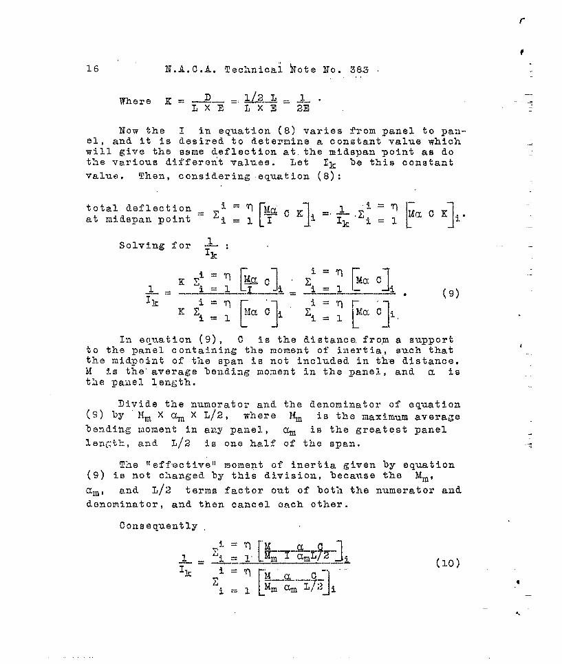
Now the I in equation (8) varies fa”om panel to pa:~-el , and it is desired to determine a constant value whichwill give the same deflection ak. the midspan point as dothe various dii’feront values. Let Ik he this constant
value . Theri, considering equation (8):
In equation (9), C is the distance. fro,m a supportto the panel containing the moment of ii~ertia, such thatthe midpoint of the span is not included in the distanc~,M is the’ average bendiag moment in the ~anel, and a isthe pafiel.length.
Divide the numerator and the denominator of eq-~ation(S) by Mm X ~ X L/2, where l% is the naximum average
b~ndiag ~loment in any panel., ~ is the greetest panel
len~:tk, and L/2 is one half of the span.
The lteffmctivell moment of inertia given by equation(9) is not changed by this division, because the Idm,
~rfi* and L/2 terns fact-or out of both the numerator and
denominator, and then cancel ~nch other.
Consequently
(lo)
?
——
—
—
.-
.
.-
N. A. C.A. Technical Note’ No. 38*” - 17
.
.
V.” Il@MENT OF DEFLECTION BETWEEN ADJACXI?T’:PANEL POINTS
PRODUCED 3Y THE STRAIN 03’ CHORD MEMBERS
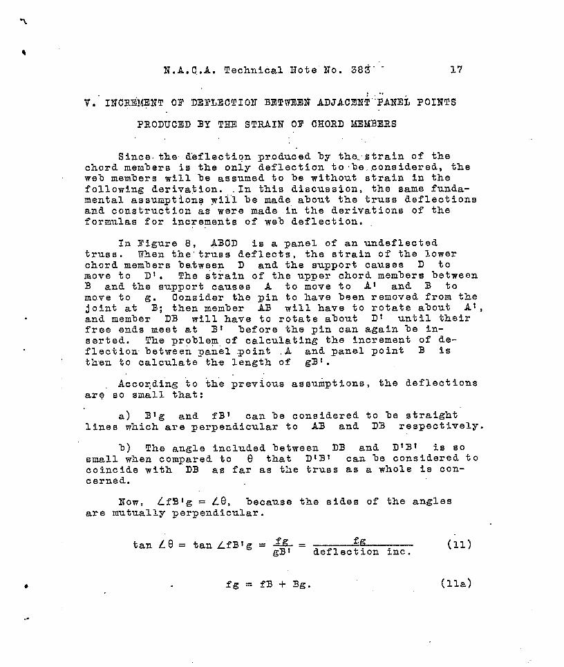
Since. the d’eflectiqn pr.oduce,d by the.strain of thechord members is the only deflection to le,.considered, theweh members will be assumed to be without strain in thefollowing derivation. .In this discussion, the same funda-mental assumptions wil”l be made about the truss deflectionsand construction as were made i-n the derivations of theformulas for increments of web deflection.,.
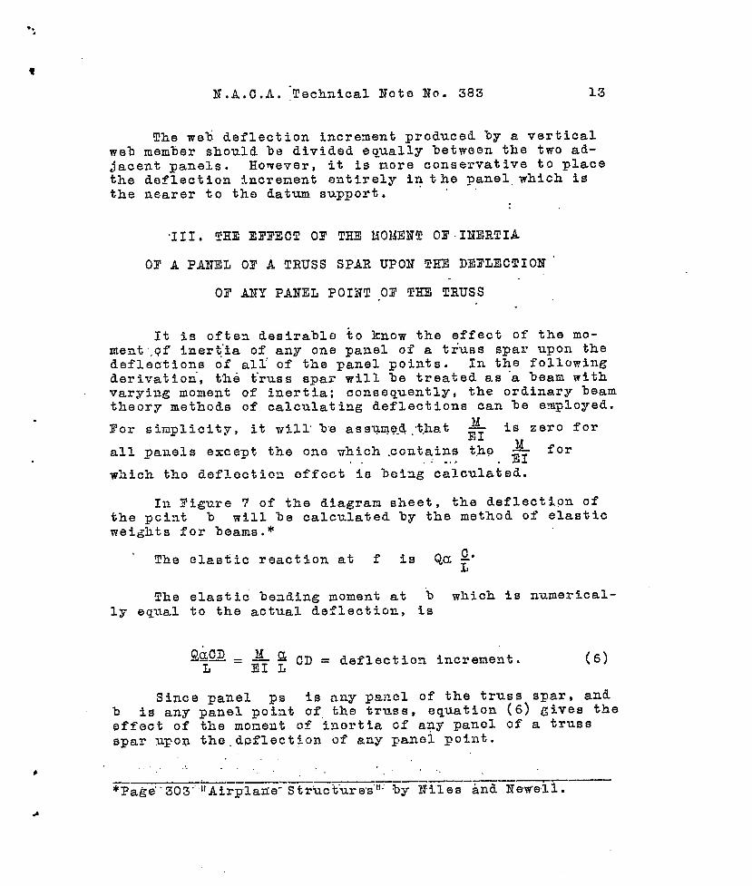
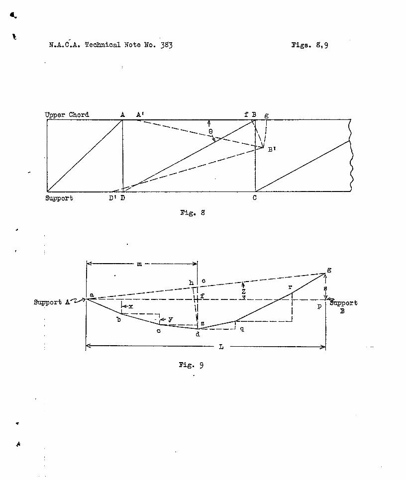
In Figure 8, A3CD is a panel of an unreflectedtruss . When the’ truss deflects, the strain of the lowerchord members between D and the support causes D tomove to D!. The strain of the upper chord members betweenB and the support causes A to move to A! and B tomove to g. Consider the pin to have %een removed from thejoint at B; theu member AB will have to rotate about At,and member DB will have to rotate about D! until theirfree ends meet at B! before the pin can again be in-serted. The problem, of calculating the increment of de-flection between panel point .A and panel point B iSthen to calculate the length of gB1.
Accoqding to th”e previous assumptions, the deflectionsarq so small that:
a) Blg and fB 1 can be considered to be straightlines which are perpendicular to AB and DB respectively.
b) The angle included between DB and DIB1 is sosmall when compared to B that DIB1 can %e considered tocoincide with DB as far as the trues as a whole is con-cerned.
Now, LfBlg = Le, because the sides of the anglesare mutually perpendicular.
tan ~e= tan ZfBIg = ~ = —~~ (11)gB 1 deflection inc.
. fg = fB + 3g. (ha)
f“
?
18 N.A.C,A, Techai.cal Note Ho. 383
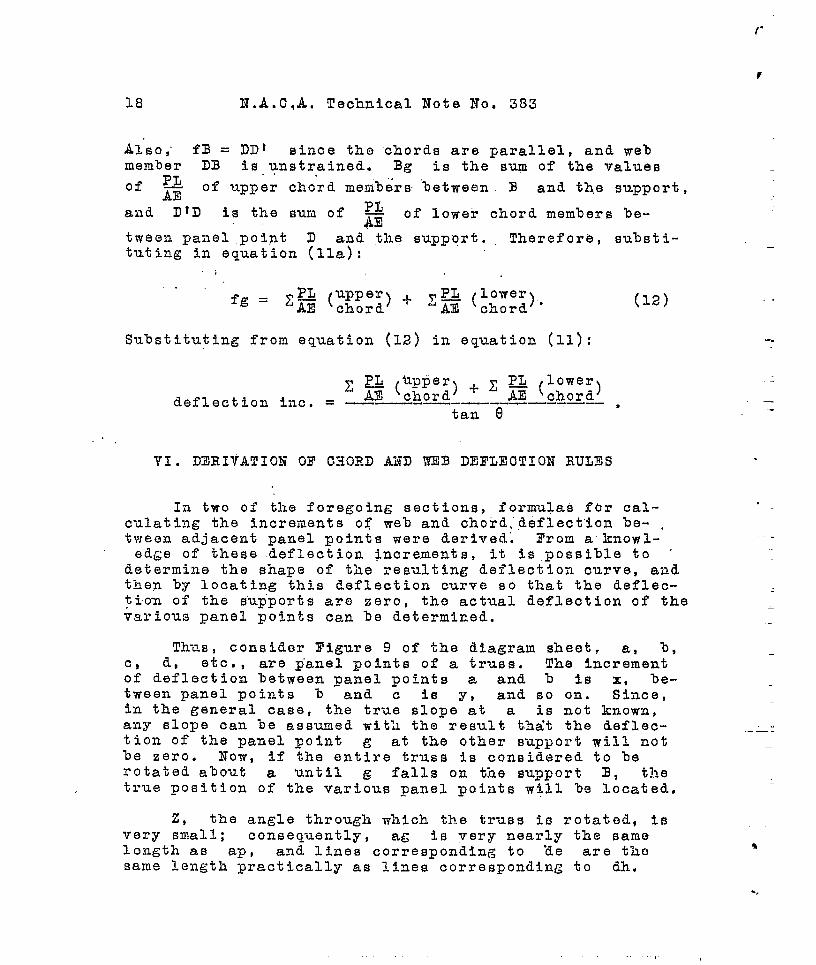
Also; fB = DDI since the chords are parallel, and webmember DB is unstrained. Bg is the sum of the valuesof P&
.
AEof upper chord menb~rs ‘between B and the support,
and DID PJ‘S ‘he ‘Um ‘f AE
of lower chord members be-
tween panel point D and the supp~rt. Therefore, substi-tuting in equation (ha):
—
fg =pL upper) + @ (;::;’).
‘A% ‘chord(12)
Substituting from equation (12) in equation (11): -.
PL lowerX ~ ‘~h~~~) + X Am ‘chord)deflection inc. = ——--—-——--——..—— *
tan (1
.
VI. DERIVATION OF CHORD AND TKE3 DEFLECTION RULZ!S .
In two of the foregoing sections, formulas for cal-culating the increments of web and choid, .d6flect”ion be- .tween adjacent panel points were d.erived.~ Prom acknow-ledge of these deflection increments, it is possible to ‘
determine the shape of the resulting deflection curve, andthen by locating this deflection curve so that the deflec-tion of the sup”ports are zero, the actual deflection of thevarious panel points can be determined..
--
—
Th-&S, consider Tigure 9 of the diagram sheet. a, b,C, d, etc., are p’anel points of a truss. The incrementof deflection between panel points a and b is x, be-tween panel points b and c is y, and so on. Since,in the general case, the true slope- at a is not known,any slope can be assumed with the result t.%it the deflec-tion of the panel point g at the other support will not%6 zero. Now, if the entire truss is considered to berotated a%out a until g falls on tine support B, t~~etrue position of the various panel points w~ll be located,
.,
—
z, the angle through which the truss is rotated, tsvery small; consequently, ag is very nearly the samelength as @p , and lines corresponding to “de are thosame length practically as lines corresponding to dh.
%
h
N. A. C.A. Technical Note No. 383 19
.
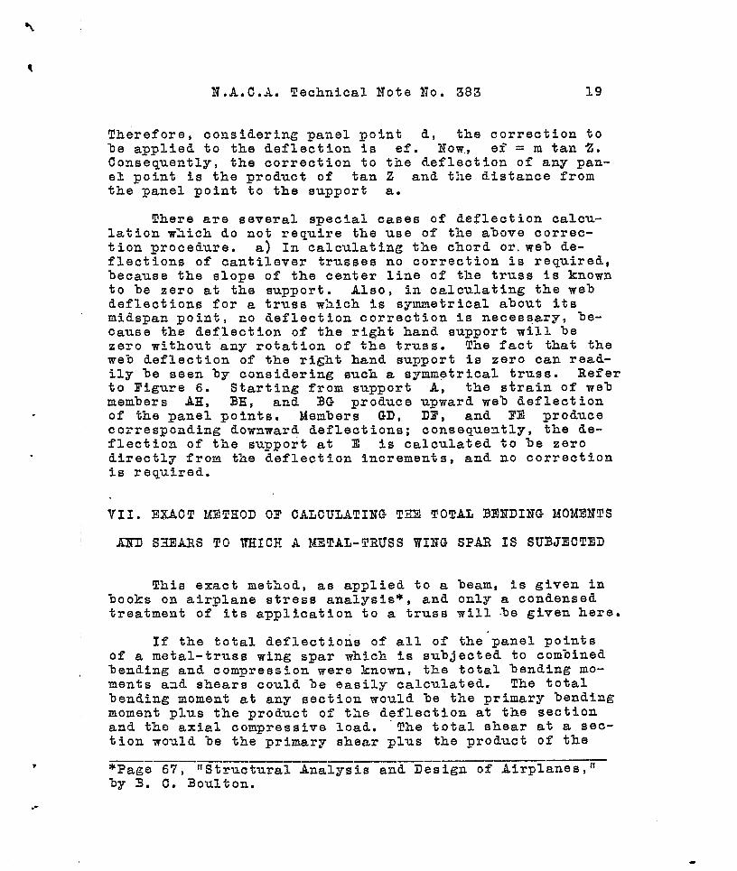
Therefore, considering panel point d, the correction tohe applied to the deflection is ef. Now., ef = m tan Z.Consequently, the correction to the deflection of any pan-el point is the product of tan Z and the distance fromthe panel point to the support a.
There are several spec%l cases of deflection calcu-lation which do not require the use of the a%ove correc-tion procedure. a) In calculating the chord or, web de-flections of cantilever trusses no correction is required,because the slope of the center line of the truss is knownto be zero at the support. Also, in calculating the webdeflections for a truss which is symmetrical about itsmidspan point, no deflection correction is necessary, be-cause the deflection o.f the right hand support will bezero without any rotation of the truss. The fact that theweb deflection of the right hand support is zero can read-ily be seen by considering such- a symmetrical truss. Refer
to Figure 6. Starting from support A, the strain of webmembers AH, BH, and BG produce upward we?) deflectionof the panel points. Members GD, DF, and FE producecorresponding downward deflections; consequently, the &e-flection of the support at E is calculated to be zerodirectly from tine deflection increments, and no correctionis required.
VII. EXACT METHOD OF CALCULATING T&II TOTAL BENDING MOMENTS
1JXD S3EARS TO WHICH A METAL-TRUSS WING SPAR IS SUBJECTED
This exact method, as applied to a beam, is given inbooks on airplane stress analysis*, and only a condensedtreatment of its application to a truss mill be given here.
If the total deflectioris of all of the’panel pointsof a metal-truss wing spar which is subjected to combinedbending and compression were known, the total bending mo-ments aad shears could be easily calculated. The totalbending moment at any section would be the primary bendingmoment plus the product of the deflection at the sectionand the axial compressive load. The total shear at a sec-tion would be the primary shear plus the product of the
————.— ——__ _*Page 67,
—.—llStructural Analysis and Design of Airplanes~l’
by 3. C. 3oulton.
,-

20 N.A.C.A, Technical Note’ No. 383.
slope of the elastic curve at the section aad the axialcompressive load.
The total deflections can be obtained by a repeateddeflection calculation process. The deflections producedby the side load can be calculated by any standard deflec-tion method. The first secondary bending moments can beo%tained by rmltiplying the primary deflections by theaxial load. The secondary shears can’ be obtained by mul-tiplyin~ the slopes of the elastic curve of the primarydeflections by the axial load. The increase in the loadsof the various members of the truss spar produced by thesecondary bending moments and shears can be calculated byany standard truss analysis method. Then, a new set ofpanel point deflections can be calculated from the newloads by ordinary deflection nethods. This process can hecontinued until the increase of deflection becomes negli-gible; consequently, the total deflections of the trussspar can be deterni.ned.
This exact method offers a neans of checking the valueof effective moment of inertia calculated by the methodsdeveloped in the previous parts of this thesis. In generalthe approximate method will give results which are 3-5$more conservative than will the exact method. Consequentlythe approximate method is entirely satisfactory for prac-tical design work, and should be used instead of the exactuethod because it is so much shorter.
PE4CTICAL RESULTS
The theory which has been developed shove has two im-porta~t practical applications. One is the calculation ofthe effectiwe moment of inertia of a truss spar from the~eometry of the spar and the l’oads to which the spar is tobe, subjected. The second is the determination of the mosteconomical location qf metal for stiffening a truss sparwhich has too much deflection.
Ca].culation of effective monent of inertia.- The of-—— ——————..—- —fecti~~-~~~~~t—of inertia is calculated fi~~-~~uation (10)of the theoretical derivations.
—

N.A. C..4, ~echnical Note No: 383. . 21
Equation (10) is: .., ,.,,
where Ik is the effective moment of inertia of the. metal
truss spar.
&
%is the bendinq ~oment wei~ht of a panel, and is
determined by dividing the average bending moment in apanel by the maximum of the average bonding moments in thepanels of the truss.
& is the panel len~h weight of a panel and is de-%
—— --
ternined by dividing the length of a panel by the maximumpanel len~th. .
+-zis the distance from support weight of a panel,——- ——--
and is determined by dividing the distance from the middleof a panel to the nearest support by one half the lengthof th-e span of the truss spar.
m is the number of panels..
T is the corrected chord moment of inertia of a pan-el, ~his corrected chord noment of inertia is. calculatedfrom equation (5) of the derivations. Equation (5) is:
1 ~ (62 - 81)—=r
+c MX2 “
dzAuALIc is the chord moment of inertia and equals —
(approximately) , where
~+ AL
d is the distance between chordcenter lines, Au is the cross-sectional area of the up-per chord, and Az is ,the cross-sectional area of the
lower chord.
-,
●
62 - 61 is the difference in the web deflection in-crements of adjacent panels. For parallel chord trusses,
..
.
,a
.
22 N.A.C.A. Technical Note No. 383
/3 is the sum of the -_-$&—AE CO,S ~
values of all of the web
members within the panel.” {s,s&’eq,, (~). ) For nonparallel
~ is the sim Qi”t~&””’p& f& values fOrchord trusses,
all web members within the panel. (S~b eq. (2). ) Angles
-or v> and a are illustrated in Figures 1 and 2 and areexplaiiled in Section I,of the th?,or.y.
. . .-
M is the bending moment at the panel point in ques-tion.
,,
X is the ~anel length.
The value of I oltained from equation (5) is thecorrected moment of inertia at a panel point. Since acorrected moment of i~ertia for a panel is required, thevalues of I at the two panel points of a panel must beaveraged.
The following procedure will be found expedient incalculating the effective moment of inertia:
1) Calculate the loads in all of the members of thetruss spar when only the side load is acting.
2) Obtain the corrected values of moments of inertiafor all of the paaels.
3) Calculate the bending moment weight, the panellength weight, and the distance from the support weightfor each panel.
4) Obtain the produc,t of the three types of weightsfor each pa~el.
5) ldultiply tile inverse of the corrected moment ofinertia in each panel by the products of the weights ofthe panel.
6) Divide the sum of the products obtained in 5) forall panelsi by the sum for all panels of, the products ob-tained ia 4). The reciprocal of this quotient is the ef-fective moment of inertia of the metal truss spar.
Some of the terms of equation (10) depend upon theloads in the iflenbers of the truss spar, If a metal truss
-.,.
—.—
.-
.
—.
—
.
.
.
,
I?.A. C.A. Technical Not”e ~o~~ 383 23
spar is subjected to combined bending and compression, theloads in the various members cannot be calculated. untilthe effective moment of inertia is known. Consequently,the primary loads ti~st be used in solving equation (10)for the effective moment of iaertia. This approximationis good because the ratio of the chord member load to webmember load in a panel does not differ greatly between thecondition where sid’e load. is acting alone and the conditionw’he~e side load is acting with axial load.
However, if greater accuracy is desired, equation(lo) can first be solved assuming that only side loads areacting. The calculated value of effective moment of iner-tia Cail then be substituted in the Precise l?ormulas and thetotal bending moments a“nd shears determined. From thesevalues of moments and shears, the loads in the various mem-bers can be calculated. Equation (10) can be solved againwith these new loads, and a more accurate value of effect-ive moment of inertia is obtained. This process can berepeated until the effective mome-nt of inertia is as ac-curate as the designer desires.
Economical location of metal for stiffening.- If a.—.-— — ——-—- -——metal-truss spar 3.s found to have too much deflection, itis desirable to know th6 panel in which a given increasein the size of chord members will produce the greateststiffening effect.
Equation (10) of the theoretical derivations givesthe designer the necessary information for economical lo-cation of metal for stiffening.
It is apparent from that equation that the quantitieswhich are important in selecting the panel for economicallocation of metal for stiffening are the bending moment
weight , Mg’
and the distance “from support weight, -CLF”
Since an addition of metal to the chord members of a panelincreases 1, this increase in metal is going to have thegreatest effect in the panel where an increase of I willhave the greatest effect. It is obvious that I will havethe greatest effect upon Ik, the effeCtiVe moment of in-
ertia, ia the panel where X.x c is a maximum. Thus ,Mm L~
the panel in which the chord members are to be increased.in size should be the one which has the largest product ofbending moment weight and distance from the support weight.
..
-- .-

*’
.-
24 N,A.C.A, Technical Note No. 383
“APPENDIX
In the body of this thesis, several purely theoret-ical concepts have ‘Deen developed. In this appendix, thenumerical application of these concepts to a practicalmetal.-tr-os’swin: spar will “he made. This practical trus~has previously been subjected to lateral and axial load,and the deflection of its panel points measured. By usingthe theoretical concepts, the deflections of the panelpoints under the ’sar.leloading are calculated. This re-sulting set of measured a~d calculated deflection valueswill ena-~le one to check the accuracy of the theory usedin determining” t-ne calculated values. ~ne metal-trusS
spar used in the following calculations was titiiltandtested by the.Boeing Airplane Company.* . ,
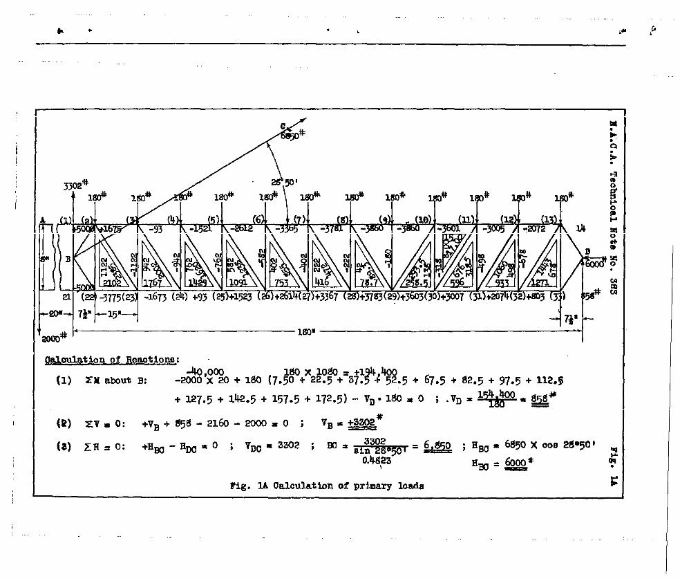
Figure 1 of the apyendix is a line diagram of thetest truss spar aad shows the type atid i.~tensity of theload to which “the ‘spar was subjected. End moment was “placed upon the truss spar at the left support by neans .
of a 2000.lb. weight on the end of the steel plate, AB,The truss spar was l~aded at its ;mnel points by moans ofmetal straps }7hich carried ~eight~ at their lower ends. .
T%..eccmnection”of strut B(2 to the spar at B is ac- “complished by a pin, and the okher end of BC is con-nected to a foundation which is s~tfficiently distant fromB to allow the axis of member EC to r,eprescnt the di-rection of the load carried by BC. The spar is supportedat D by another pin connection.
The angularity of member BC places axial compres-sion io the truss spar, which compression ig a function ofthis angularity, and of” ths spar reaction at 3.
The deflections at several panel points of the sparwere measured Then the spar was deflected under the loading~%~wn in ~ig~re 1.
The abject of the following set of comptttations is tOcelculate thL? deflections of the truss spar Q% thO panelpoints where the deflections ~ere actually measured in thetest, and under the saae loa~ing as that used in the test.
. ....——.—-—---—---.——..——-——.-—.—-—————*see Test No. 1~~~~, 3ocing Airplane Conpa.ny, Seattle,Washington,
..
.
.
‘N.A.C.A. Technical Note No. 383 25 ‘.
Outline of calculati~~.-———-—-.—
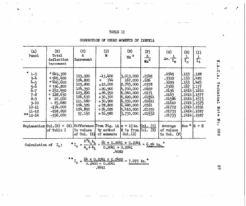
1) The chor”d moments of inertia of the variouspanels are corrected for web deflection.
2) The effective moment of inertia of the trussspar is calculated from the corrected moment of inertiavalues .
3) This effective value of moment of inertia issubstituted in the proper Precise Formula for deflection;consequently, the deflections of the spar under the loadings~.own in Figure 1 are determined. Since the deflectionshave been measured under the same loading, a comparisonbetween the measured deflection values and the calculateddeflection values is had.
Explanations and Assumptions.- Panels (1-2) and (13-.——14) are not considered separately because it is impossibleto determine the cross-sectional areas of the mem%ers ofthese panels. These areas are indeterminate because gus-set plates are included between the chord and web members,
Since the cross-sectional areas are indeterminate,some sort of approximation is necessary if the web deflec-tion effect upon chord moment of inertia is to be calcu-lated. It seems reasonable to assume that tho effect ofweb deflection in panels (l-2) and (13-14) is the same asthat of the corresponding adjacent panels (2-3) and (12-13). It would probably be more accurate to assume the webdeflection effect of panels (1-2) and (13-14) to be zero,since the area of the gusset plates is quite large. How-ever, it is more conservative to assume the deflection ef-fect to be greater than zero, so the first mentioned de-flection assurrption is used in the calculations.
●
✎☛

.
TABLE I
WEEIDEE!LVCTIOMIWEIMIWCS
(A) (B) (c) (D) (E) (r) (G)Web member Loed ~ Web member Loed
~ % n (vertical)PL
(aiegollal) (lb.) A (lb.) A COB q
2-23 -1-2y35. 277,0002W,O(KJ
i-t-2 -1122 61,300
-24L
2002. 232,km g4,0co 2 1,4001620. u% 000 399,~ 5-25 % z1,600
Z-2 12y3. 143,700 305,m 5-26 g2
1031,s00 ‘
-27 9 ,200t;;: z
7-27 2 21*950?-28 5 ,s00 ::::;: &2g 222 12,130&2g gg.~ 10,370 22,000 _29-10
2;2:;34,050 10-30 m
lE :3& ;17,y30
30-11 78,500 11-31.31-12 1060. 123,100
27,200263,m 12-32 6$ 37,050
32-13 1443. 167,700 350,~ . —
Eq@nationL =17.00 in.
Fig. ~A = ;1464 sq.in. co= 11‘:
3i.g.IA Fig. IL cOB~ = 1*00A = 0.1464 Sq.in.
. . ,.
c1
!2o-
0“.
.-
1. . ,*
(A)
Panel
* 1-
Lt‘55-66-77-8
w9-1010-1111-12
**12-14
EK@mation
(B)Tot&l
deflectionticranent
+645, 00-1-@
h-1- :600+j36,800
+232,450+12g,630+ 22,000- 6g,660-1* ,000-29g,a50-356,000
01.(D)+ (G)f Table I
(c)A
kcrement
10 ,900?10 ,WO
103,gal104,350103,Wil106,630111,680”104,320104,g5057,150
)ifference.DvaluesIiCol. (B’
(D) (E)M ,& a
(F)A7%x
-13,400+ 71A+12,200+.20,!330+26,950+30,300+30,p+ 2&Wcli-24,020+16,5Ea I
3,0~3,m167,000
2,743,003
6:%$6,F20,w6,930,0006,480,0005,41O,OW3i730,m
.0345
.626
.0378
.0222
::$1.01611.0161S01935.01532
iEisi+2%F’PT.0345 .153.3302 .153
.3299 .1 3
.03cil 2.17
.0196 .1414
.0163 .1414
.01586 .1414
.01610 .1414
.01772 .1414
.01733 .1414
.01733 .1414i
.T
A..erage Soo *)fVelllosm Col. (F)
4
.-.4CM2
**Ic .64 x o.2&1 X 0.2400
0.2400+ 0.2041=7.075 in.d,
.4441
(I)1g
lW4@4$3317716101577157315751591158715s7
.+E
.
i-..c1
Elm
.+’
N-a

Panel
1-
2L526-7;-;
9:1010-1111-3212-14
(A)AT.M
-26,7m-6, 2g
$+ 6, 70+16$550+23 ,925+2&625-t’30,60a+29,g50+ 26,410+ 20,3W+ g,2$Kl
.verageof),Table II
(B)llomentweight
.8725
.2066
.2112
.541
:;$1.000.976.g635.663.271
%iii530:
(c)Panellengfi
22.535.015.015.015.015.015.015.015.015.022.5
rig.IA
(D)Panelweight
1.000.667.667.667,667.667.667.667.667.667
1.000
~.
(E)Oist. frorl
support
11.25
i5-0.00
60:%g.g
pCJ
45:0030.0011.25
lug. IA
(1.?)lMElt.
weight
.125
●333.500.667.&g
1.00
::2;.500
.333
.125
(G)Totalwei~t
.1091
.045g
.0705
.2410
.43E.62
● 55z
● 35.2W.1&72.0339
:Bxm)
2.9/345
L=yjgyq .
It = 5.76 in.4
(H)~It
.lgg
-w.%.177.1610.1577.1573.1575.1591.15s7.15g7
!o1.(I)!ableII
(I)Roall.cts
.0205
.Om
P●o
:G)X (H)
.51m3
Nm
.*
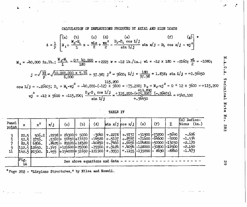
‘~~ –o+ 40.000 .+222; w .-1,2 ~~./i,B.;WL = -12 x lgO = -~60: ~ ‘M= = -40,000 in.lb.;y -Mo
-10s0:
j =F+= Q@Q&&+@ = g7.9g; Ja = 9600; L/j = m‘ l*g3g; ‘in LIJ =+009645097.9g
Cos L/j = -.26403;DI = ~-wJ2 = 443,000-(-12~~’7&k = +75,2CM3;D,= M~wj 2 = o + 12 x 9600 =+115, .ZOO
;*?M (-.26403)= +,~ ,@D2-D1 cos L/j =+1~5,~~(+Wja = -12 X 9600 = -115,200;
sti L/~#
-1-.96450
‘T! IV
Panel ~1 (H) Ddl.ec-
Xz dii (c) (b) (4 sin X/j Cos X/j (e) (f) z tires (in.)poht
3 22.5 506.2 .229s-t-2400 + 5000 -040 + .227g +.9737 -31900 -~ -364o2 2 b
-.606
5 52.5 2756.d.560 + 5650 +11670 -1520 -t.510 -1-.qi97-71600 -
i-9200 -1.534
7 g2.~ 6s06. . q + 13gloo+lgyo -40@m + .746 +. fw -l@goo -5~ -13030 -p.~709 112.5 12650. 1.149 +121600-1-%jOm -75900 -I-.9124 + .4094 -128030 -30s00 -12900 -2.15011 142.5 20300. 1.455 +154000 +33.650-Wlwo + .9933 +.1155 -139m - ~w -g~ -1=473
Fig.u
Seeabove ecpationstitita - ---------------- ----
*Page 202 - mMr-plmo structures,n by Nile~ d Newell.
●✎
☞✜
,
.
.
N.A.C,A. Technical Note ”No. 383
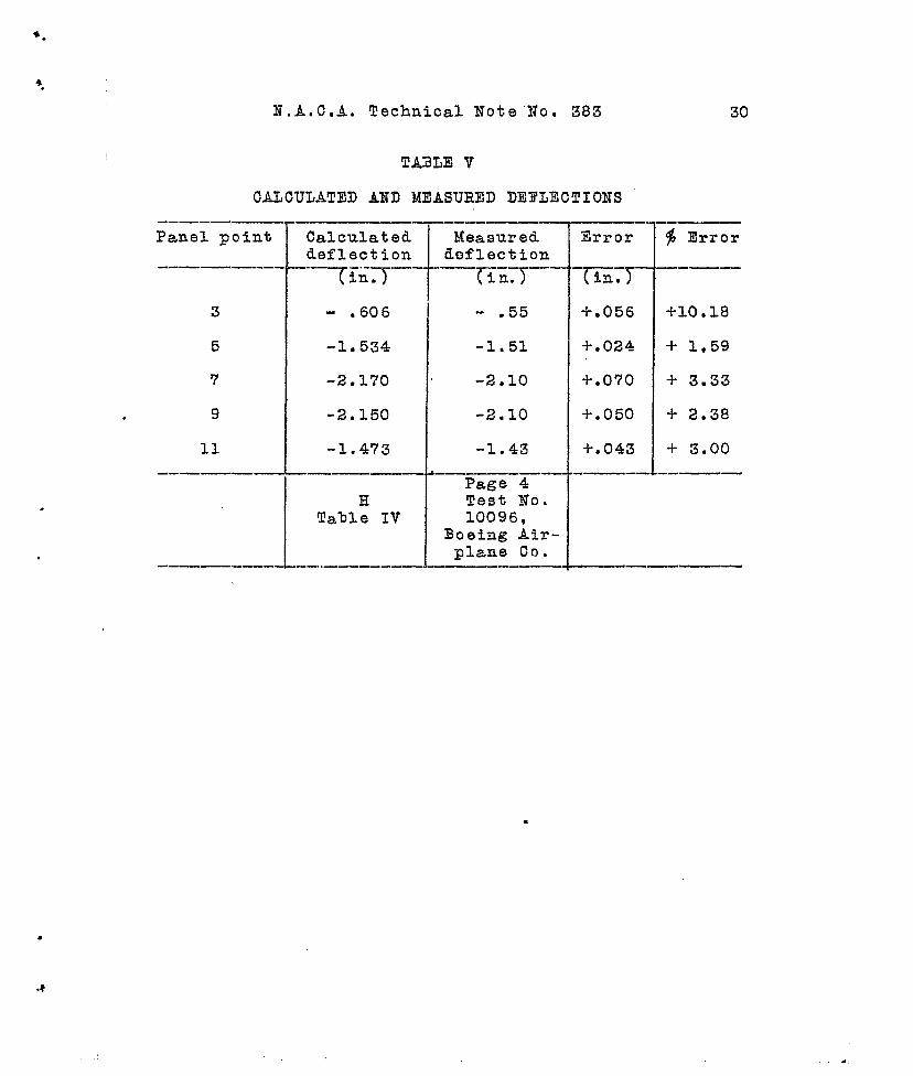
‘i!Ai3LEV
CALCULATEI) AND MEASURED DEFLECTIONS
-——— —-—
Panel point
--—— —.—.
3
5
‘7
9
11
-—————
Calculateddeflection
–.=liT–-
-, 606
-1.534
-2.170
-2.150
-1.473
HTable IV
--—
Measured.deflection
-—EG:T–-”
.55
-1.51
-2.10
-2.10
-1.43
Page 4Test No.10096,
Boeing Air-plane Co.
—----Error
-l’-Iim-
+.056
-i-.O24
+.070
+.050
+.043
30
.-—$ Error
—-
+10.18
+ 1.59
+ 3.33
+ 2.38
+ 3.00
.-———
.
.

9.
4.
.
IZ.A.,C.A. Technical Hote No. 383 31
conclusionr3.- An exa~~inatioa of Table V shows thatthere is good agreement between the measured and calcu-lated tleflection values. Yhus, although the method usedin calculating the effective moment af inertia containsseveral approximations, tho Good agreement between thetwo sots of deflections shows that the effective momentof inertia has been calcuI.ated fairly accurately.
The greatest percentage of error occurs at a pointwhich is very close to the support whqre ead moment isapplied. Since the method used in calcuiatiag the ef-fective noment of inertia was based upon having the max-imum ordinate accurate and the other ordinc.tos only ap-proxinatol~” 50, the greatest porcentago of error wouldnaturally he expected to bo at points near the supports.The error in inches does not vary as much from one endof the span to the other as does the perce~tage error,because at the points of small deflection, any error atall produces a large percentage of error. Also, smallerrors in the measurement of deflections produce largepercentage errors in the deflection values if these val-ues are very snail. Consequently, a sizable portion ofthe percentage ‘terrori[at points of small deflection canbe attributed to measurement errors in the deflectiontest.
Since the calculated deflection values are greaterat all panel points than the measured deflections, theeffective mome~t of inertia must have been calculated intoo conservative a manner. There were two assumptionsmade in the calculation of the effectivo nonent of in-ertia which wero obviously conservative. One was the as-sumption that the panels containing the gusset plates hadas nuch shear deformation as the adjacent panels whichdid not contain gusset plates. The second assumption wasthat the elastic curve was represented by the deflectedposition of the panel points of the lower chord nenber,which paael points were deflected more under load thanthe panel poiats of the upper chord. A nore accurateprocedure would have bees to consider the elastic curveof the truss spar to bo an average ‘of tho upper and lowerchord defloctior. polygons.
li.A.C.A.Technical l?oteNo.sgJ
A
I
Diagram
,
.
B
Fig.1
c
//
//
//
v
D
/
c
Fig.2 .
A
~ N
●
.
iI
I
1
AC*
(1) XH abut B:
{2) ZV s o: +VB +
-40 ,Oco y’%lm x loao = +1-2000 X 20 + 1~ (7.50 + 22.5 + 37. 45 .5 + 67.5 + 82.5 + 97.5 + 112.5
+ 127.5 + 142.5 + 157.5 + 172.5) - VD-l$O = 0 ; .VD=*=W
85s#
- 21&l - 2000=0 ; ‘?B. +=
(a) ZH=O: +Ei~-Hm=o ; vD0=3~2 ; m= i$%#= ~ ; HBO= 6%OX 00S ~Wjol
\ Em = =*
Fig. IA Calculationof primary load
+->
~ N.A.C.A. Technical Note No. JgJ Figs. 4,5,6,7A
———— —.. — ———— ——— ———— . D
B-
Fig.h
A ——— ———— —— ––––––––l:––––I
–––’––––––4 .t‘b
cFigs
.
,
Load Load
Fig.6
Load
lb f
Fig.7
IiN.A.C~A. Teohnical Note No. “Sgs
.
rigs. g,g
Upper Chord A Al fB g-b
-- ‘i’-1- e
//“*#---
/Support D! J) c
Fig. 8
r
Support
.
‘
Fig. 9