conveyor idler and accessories · pdf filewe are your bulk material handling specialists...
TRANSCRIPT
W e a r e y o u r b u l k m a t e r i a l h a n d l i n g s p e c i a l i s t s
Conveyor Idler and Accessories Catalogue
Idler Catalogue Front Cover for Web Sept 23 2010.indd 1 9/23/2010 3:52:46 PM
W o r k i n g F o r T h e S u c c e s s O f O u r C u s t o m e r
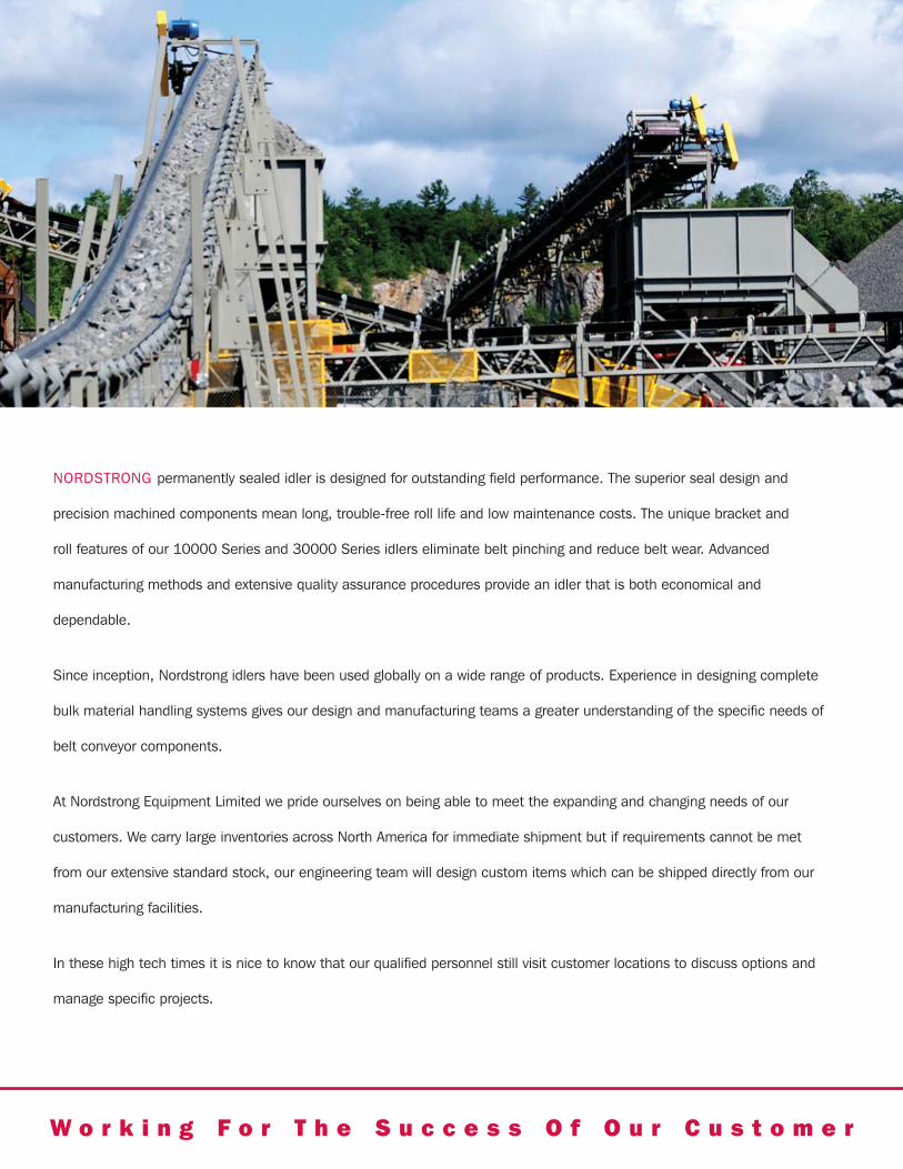
NORDSTRONG permanently sealed idler is designed for outstanding field performance. The superior seal design and
precision machined components mean long, trouble-free roll life and low maintenance costs. The unique bracket and
roll features of our 10000 Series and 30000 Series idlers eliminate belt pinching and reduce belt wear. Advanced
manufacturing methods and extensive quality assurance procedures provide an idler that is both economical and
dependable.
Since inception, Nordstrong idlers have been used globally on a wide range of products. Experience in designing complete
bulk material handling systems gives our design and manufacturing teams a greater understanding of the specific needs of
belt conveyor components.
At Nordstrong Equipment Limited we pride ourselves on being able to meet the expanding and changing needs of our
customers. We carry large inventories across North America for immediate shipment but if requirements cannot be met
from our extensive standard stock, our engineering team will design custom items which can be shipped directly from our
manufacturing facilities.
In these high tech times it is nice to know that our qualified personnel still visit customer locations to discuss options and
manage specific projects.
Idler Catalogue Front Cover for Web Sept 23 2010.indd 2 9/23/2010 3:52:38 PM
Nordstrong Equipment Limited Idler Catalogue
Conveyor Idler and Accessories CatalogueAn Introduction to our Idler Selection .............................................................. 2Ordering Information ........................................................................................ 410000 Series (CEMA B) ..................................................................................... 6
Troughing Idlers ............................................................................................................................................... 7
Impact Idlers .................................................................................................................................................... 8
Self-Training Idlers ........................................................................................................................................... 9
Return Idlers ...................................................................................................................................................10
Self-Training Returns ......................................................................................................................................11
30000 Series (CEMA C) ................................................................................... 12Troughing Idlers ..............................................................................................................................................13Impact Idlers ...................................................................................................................................................1435° Cable Suspended .....................................................................................................................................150-45° Adjustable Trough Idler ..........................................................................................................................1520° Picking Idlers ............................................................................................................................................16Self-Training Idlers ..........................................................................................................................................17Return Idlers ...................................................................................................................................................18Self-Training Returns ......................................................................................................................................19Live Shafts ......................................................................................................................................................20
35000 Troughing Idlers (CEMA C) ................................................................... 2140000 Series (CEMA D) ................................................................................... 22
Troughing Idlers ..............................................................................................................................................23Impact Idlers ...................................................................................................................................................24Self-Training Idlers ..........................................................................................................................................25Flat Return Idlers ............................................................................................................................................26Self-Training Returns ......................................................................................................................................27
50000 Series (CEMA E) ................................................................................... 28Troughing Idlers ..............................................................................................................................................29Impact Idlers ...................................................................................................................................................3020° Picking Idlers ............................................................................................................................................31Garland Idlers .................................................................................................................................................3210° VEE Return Idlers .....................................................................................................................................33Live Shafts ......................................................................................................................................................34Self-Training Returns ......................................................................................................................................35Flat Return Idlers ............................................................................................................................................36Self-Training Idlers ..........................................................................................................................................37Picking Idlers ..................................................................................................................................................38
Accessories ................................................................................................... 39Guide Rolls .....................................................................................................................................................39Stub Idlers ......................................................................................................................................................40Pipe Conveyor ................................................................................................................................................41Impact Beds ....................................................................................................................................................42Protected Screw Take-Ups ..............................................................................................................................43Pull Cord Switches ....................................................................................................................................44, 45Conveyor Pulleys .......................................................................................................................... 46, 47, 48, 49
Table of Contents.indd 1 9/27/2010 12:42:48 PM
2 Nordstrong Equipment Limited Idler Catalogue
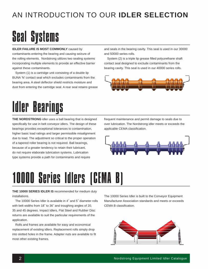
IDLER FAILURE IS MOST COMMONLY caused by contaminants entering the bearing and causing seizure of the rolling elements. Nordstrong utilizes two sealing systems incorporating multiple elements to provide an effective barrier against these contaminants.
System (1) is a cartridge unit consisting of a double lip BUNA ‘N’ contact seal which excludes contaminants from the bearing area. A steel defl ector shield restricts moisture and dust from entering the cartridge seal. A rear seal retains grease
and seals in the bearing cavity. This seal is used in our 30000 and 50000 series rolls.
System (2) is a triple lip grease fi lled polyurethane shaft contact seal designed to exclude contaminants from the bearing cavity. This seal is used in our 40000 series rolls.
AN INTRODUCTION TO OUR IDLER SELECTION
Idler Bearings
Seal Systems
THE NORDSTRONG idler uses a ball bearing that is designed specifi cally for use in belt conveyor idlers. The design of these bearings provides exceptional tolerances to contamination, higher basic load ratings and larger permissible misalignment due to load. The adjustment so critical to the proper operation of a tapered roller bearing is not required. Ball bearings, because of a greater tendency to retain their lubricant, do not require elaborate lubrication systems. Lubrication type systems provide a path for contaminants and require
frequent maintenance and permit damage to seals due to over lubrication. The Nordstrong idler meets or exceeds the applicable CEMA classifi cation.
THE 10000 SERIES IDLER IS recommended for medium duty installations.
The 10000 Series Idler is available in 4˝ and 5˝ diameter rolls with belt widths from 18˝ to 36˝ and troughing angles of 20, 35 and 45 degrees. Impact Idlers, Flat Steel and Rubber Disc returns are available to suit the particular requirements of the application.
Rolls and frames are available for easy and economical replacement of existing idlers. Replacement rolls simply drop into slotted holes in the frame. Adapter nuts are available to fi t most other existing frames.
The 10000 Series Idler is built to the Conveyor Equipment Manufacturer Association standards and meets or exceeds CEMA B classifi cation.
10000 Series Idlers (CEMA B)
01_Intro_+10000_Series_Idlers_Adjusted Sept 2010.indd 2 9/24/2010 9:45:30 AM
Nordstrong Equipment Limited Idler Catalogue 3
30000 Series Idlers (CEMA C)
40000 Series Idlers (CEMA D)
50000 Series Idlers (CEMA E)
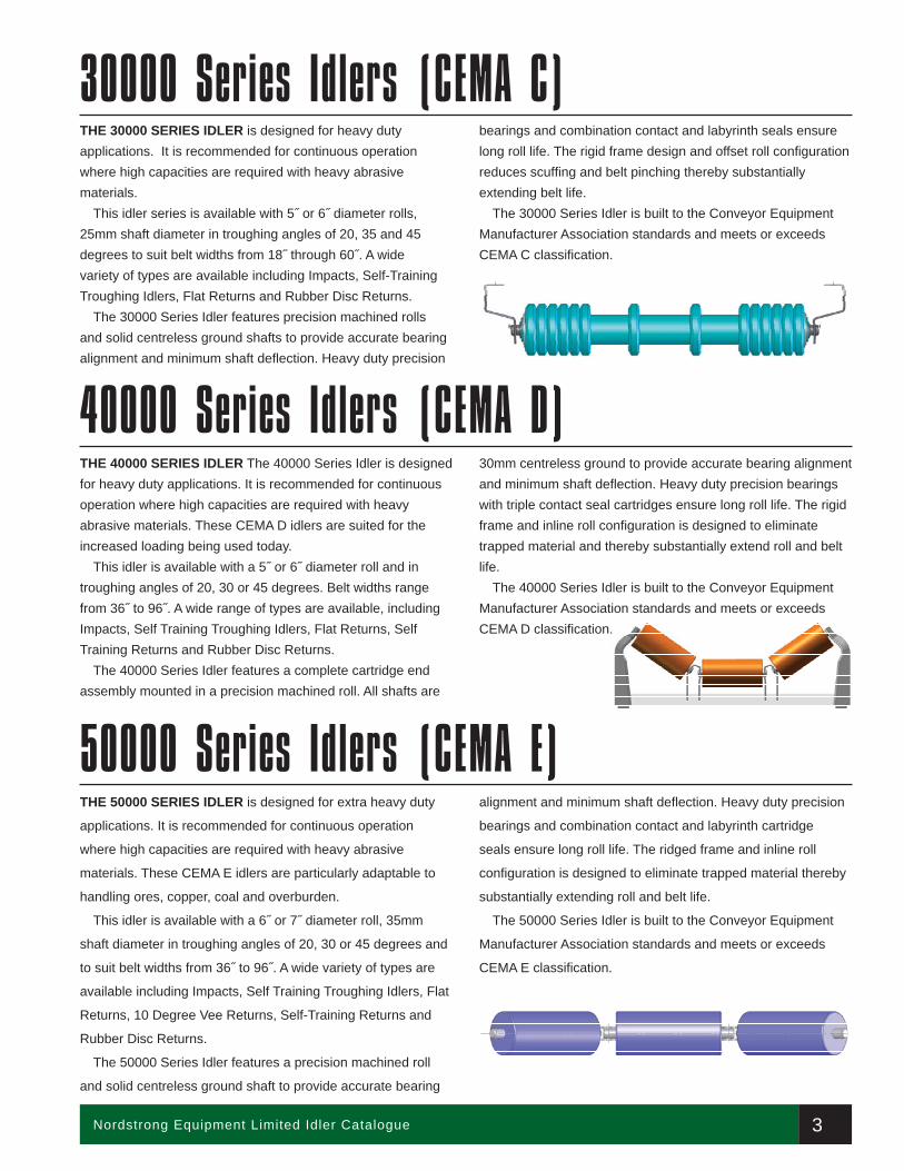
THE 30000 SERIES IDLER is designed for heavy duty applications. It is recommended for continuous operation where high capacities are required with heavy abrasive materials.
This idler series is available with 5˝ or 6˝ diameter rolls, 25mm shaft diameter in troughing angles of 20, 35 and 45 degrees to suit belt widths from 18˝ through 60˝. A wide variety of types are available including Impacts, Self-Training Troughing Idlers, Flat Returns and Rubber Disc Returns.
The 30000 Series Idler features precision machined rolls and solid centreless ground shafts to provide accurate bearing alignment and minimum shaft defl ection. Heavy duty precision
bearings and combination contact and labyrinth seals ensure long roll life. The rigid frame design and offset roll confi guration reduces scuffi ng and belt pinching thereby substantially extending belt life.
The 30000 Series Idler is built to the Conveyor Equipment Manufacturer Association standards and meets or exceeds CEMA C classifi cation.
THE 40000 SERIES IDLER The 40000 Series Idler is designed for heavy duty applications. It is recommended for continuous operation where high capacities are required with heavy abrasive materials. These CEMA D idlers are suited for the increased loading being used today.
This idler is available with a 5˝ or 6˝ diameter roll and in troughing angles of 20, 30 or 45 degrees. Belt widths range from 36˝ to 96˝. A wide range of types are available, including Impacts, Self Training Troughing Idlers, Flat Returns, Self Training Returns and Rubber Disc Returns.
The 40000 Series Idler features a complete cartridge end assembly mounted in a precision machined roll. All shafts are
30mm centreless ground to provide accurate bearing alignment and minimum shaft defl ection. Heavy duty precision bearings with triple contact seal cartridges ensure long roll life. The rigid frame and inline roll confi guration is designed to eliminate trapped material and thereby substantially extend roll and belt life.
The 40000 Series Idler is built to the Conveyor Equipment Manufacturer Association standards and meets or exceeds CEMA D classifi cation.
THE 50000 SERIES IDLER is designed for extra heavy duty
applications. It is recommended for continuous operation
where high capacities are required with heavy abrasive
materials. These CEMA E idlers are particularly adaptable to
handling ores, copper, coal and overburden.
This idler is available with a 6˝ or 7˝ diameter roll, 35mm
shaft diameter in troughing angles of 20, 30 or 45 degrees and
to suit belt widths from 36˝ to 96˝. A wide variety of types are
available including Impacts, Self Training Troughing Idlers, Flat
Returns, 10 Degree Vee Returns, Self-Training Returns and
Rubber Disc Returns.
The 50000 Series Idler features a precision machined roll
and solid centreless ground shaft to provide accurate bearing
alignment and minimum shaft defl ection. Heavy duty precision
bearings and combination contact and labyrinth cartridge
seals ensure long roll life. The ridged frame and inline roll
confi guration is designed to eliminate trapped material thereby
substantially extending roll and belt life.
The 50000 Series Idler is built to the Conveyor Equipment
Manufacturer Association standards and meets or exceeds
CEMA E classifi cation.
01_Intro_+10000_Series_Idlers_Adjusted Sept 2010.indd 3 9/24/2010 9:45:33 AM
4 Nordstrong Equipment Limited Idler Catalogue
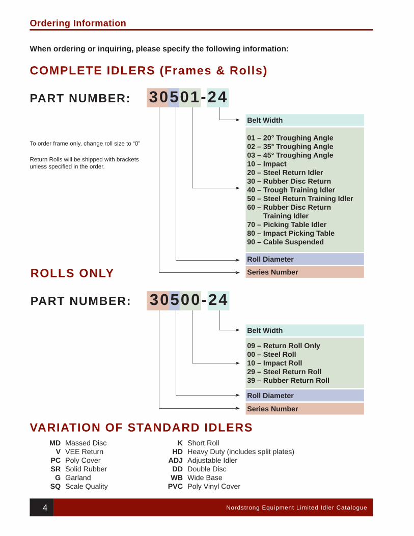
Ordering Information
Belt Width
Roll Diameter
Series Number
01 – 20° Troughing Angle02 – 35° Troughing Angle03 – 45° Troughing Angle10 – Impact20 – Steel Return Idler30 – Rubber Disc Return40 – Trough Training Idler50 – Steel Return Training Idler60 – Rubber Disc Return
Training Idler70 – Picking Table Idler80 – Impact Picking Table90 – Cable Suspended
Belt Width
Roll Diameter
Series Number
09 – Return Roll Only00 – Steel Roll10 – Impact Roll29 – Steel Return Roll39 – Rubber Return Roll
To order frame only, change roll size to “0”
Return Rolls will be shipped with brackets unless specifi ed in the order.
ROLLS ONLY
PART NUMBER: 30500-24
When ordering or inquiring, please specify the following information:
COMPLETE IDLERS (Frames & Rolls)
PART NUMBER: 30501-24
MDV
PCSR
GSQ
KHD
ADJDDWB
PVC
Massed DiscVEE ReturnPoly CoverSolid RubberGarlandScale Quality
Short RollHeavy Duty (includes split plates)Adjustable IdlerDouble DiscWide BasePoly Vinyl Cover
VARIATION OF STANDARD IDLERS
Dimensions subject to change. Use certifi ed drawings only.
10000 SeriesCEMA B
5Nordstrong Equipment Limited Idler Catalogue
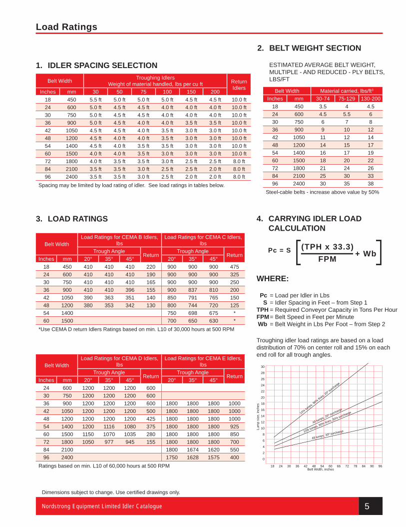
Load Ratings
1. IDLER SPACING SELECTION
Belt Width Troughing IdlersWeight of material handled, lbs per cu ft Return
IdlersInches mm 30 50 75 100 150 200
18 450 5.5 ft 5.0 ft 5.0 ft 5.0 ft 4.5 ft 4.5 ft 10.0 ft24 600 5.0 ft 4.5 ft 4.5 ft 4.0 ft 4.0 ft 4.0 ft 10.0 ft30 750 5.0 ft 4.5 ft 4.5 ft 4.0 ft 4.0 ft 4.0 ft 10.0 ft36 900 5.0 ft 4.5 ft 4.0 ft 4.0 ft 3.5 ft 3.5 ft 10.0 ft42 1050 4.5 ft 4.5 ft 4.0 ft 3.5 ft 3.0 ft 3.0 ft 10.0 ft48 1200 4.5 ft 4.0 ft 4.0 ft 3.5 ft 3.0 ft 3.0 ft 10.0 ft54 1400 4.5 ft 4.0 ft 3.5 ft 3.5 ft 3.0 ft 3.0 ft 10.0 ft60 1500 4.0 ft 4.0 ft 3.5 ft 3.0 ft 3.0 ft 3.0 ft 10.0 ft72 1800 4.0 ft 3.5 ft 3.5 ft 3.0 ft 2.5 ft 2.5 ft 8.0 ft84 2100 3.5 ft 3.5 ft 3.0 ft 2.5 ft 2.5 ft 2.0 ft 8.0 ft96 2400 3.5 ft 3.5 ft 3.0 ft 2.5 ft 2.0 ft 2.0 ft 8.0 ft
Spacing may be limited by load rating of idler. See load ratings in tables below.
2. BELT WEIGHT SECTION
ESTIMATED AVERAGE BELT WEIGHT,MULTIPLE - AND REDUCED - PLY BELTS, LBS/FT
Belt Width Material carried, lbs/ft3
Inches mm 30-74 75-129 130-20018 450 3.5 4 4.524 600 4.5 5.5 630 750 6 7 836 900 9 10 1242 1050 11 12 1448 1200 14 15 1754 1400 16 17 1960 1500 18 20 2272 1800 21 24 2684 2100 25 30 3396 2400 30 35 38
Steel-cable belts - increase above value by 50%
3. LOAD RATINGS
Belt WidthLoad Ratings for CEMA B Idlers,
lbsLoad Ratings for CEMA C Idlers,
lbsTrough Angle
ReturnTrough Angle
ReturnInches mm 20° 35° 45° 20° 35° 45°
18 450 410 410 410 220 900 900 900 47524 600 410 410 410 190 900 900 900 32530 750 410 410 410 165 900 900 900 25036 900 410 410 396 155 900 837 810 20042 1050 390 363 351 140 850 791 765 15048 1200 380 353 342 130 800 744 720 12554 1400 750 698 675 *60 1500 700 650 630 *
*Use CEMA D return Idlers Ratings based on min. L10 of 30,000 hours at 500 RPM
Belt WidthLoad Ratings for CEMA D Idlers,
lbsLoad Ratings for CEMA E Idlers,
lbsTrough Angle
ReturnTrough Angle
ReturnInches mm 20° 35° 45° 20° 35° 45°
24 600 1200 1200 1200 60030 750 1200 1200 1200 60036 900 1200 1200 1200 600 1800 1800 1800 100042 1050 1200 1200 1200 500 1800 1800 1800 100048 1200 1200 1200 1200 425 1800 1800 1800 100054 1400 1200 1116 1080 375 1800 1800 1800 92560 1500 1150 1070 1035 280 1800 1800 1800 85072 1800 1050 977 945 155 1800 1800 1800 70084 2100 1800 1674 1620 55096 2400 1750 1628 1575 400
Ratings based on min. L10 of 60,000 hours at 500 RPM
4. CARRYING IDLER LOAD CALCULATION
WHERE:
Pc = Load per Idler in Lbs S = Idler Spacing in Feet – from Step 1 TPH = Required Conveyor Capacity in Tons Per Hour FPM = Belt Speed in Feet per Minute Wb = Belt Weight in Lbs Per Foot – from Step 2
Troughing idler load ratings are based on a load distribution of 70% on center roll and 15% on each end roll for all trough angles.
Lum
p si
ze, i
nche
s
30
28
26
24
22
20
18
16
14
12
10
8
6
4
2
0
18 24 30 36 42 48 54 60 66 72 78 84 90 96Belt Width, inches
10% lumps, 90% fi n
es, 20º s
urcharge
All lumps, 20º surcharge
10% lumps, 90% fi nes, 30% surcharge
All lumps, 30º surcharge
Pc = S (TPH x 33.3)FPM + Wb
Load Ratings page.indd 1 9/24/2010 1:17:42 PM
10000 SeriesCEMA B
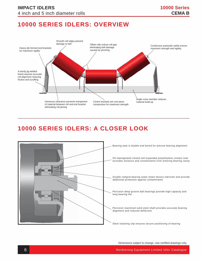
IMPACT IDLERS4 inch and 5 inch diameter rolls
Heavy die-formed end brackets for maximum rigidity
A sturdy jig welded frame assures accurate roll alignment reducing friction and scruffi ng
Generous clearance prevents entrapment of material between roll and end bracket eliminating roll jaming
Centre brackets are one-piece construction for maximum strength
Angle cross member reducesmaterial build-up
Continuous automatic welds ensure maximum strength and rigidity
Smooth roll edges prevent damage to belt Offset rolls reduce roll gap
eliminating belt damage caused by pinching
10000 SERIES IDLERS: A CLOSER LOOK
10000 SERIES IDLERS: OVERVIEW
Bearing seat is double end bored for precise bearing alignment
Oil impregnated closed cell expanded polyethylene contact seal excludes moisture and contaminants from entering bearing cavity
Double integral bearing seals retain factory lubricant and provide additional protection against contaminants
Percision deep groove ball bearings provide high capacity and long bearing life.
Percision machined solid steel shaft provides accurate bearing alignment and reduced deflection
Steel retaining clip ensures secure positioning of bearing
Dimensions subject to change. Use certifi ed drawings only.
6 Nordstrong Equipment Limited Idler Catalogue
10 000 Series Idler pages.indd 1 9/24/2010 1:14:06 PM
10000 SeriesCEMA B
7Nordstrong Equipment Limited Idler Catalogue
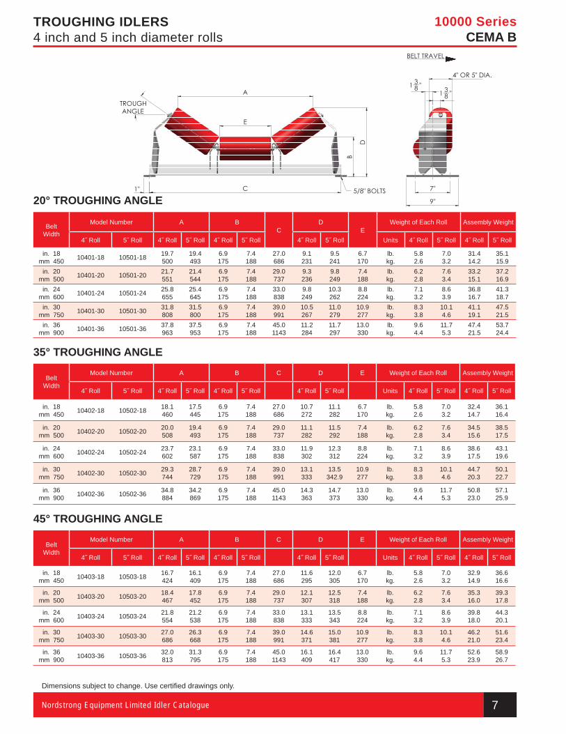
TROUGHING IDLERS4 inch and 5 inch diameter rolls
20° TROUGHING ANGLE
BeltWidth
Model Number A BC
DE
Weight of Each Roll Assembly Weight
4˝ Roll 5˝ Roll 4˝ Roll 5˝ Roll 4˝ Roll 5˝ Roll 4˝ Roll 5˝ Roll Units 4˝ Roll 5˝ Roll 4˝ Roll 5˝ Roll
in. 18mm 450 10401-18 10501-18 19.7
50019.4493
6.9175
7.4188
27.0686
9.1231
9.5241
6.7170
lb.kg.
5.82.6
7.03.2
31.414.2
35.115.9
in. 20mm 500 10401-20 10501-20 21.7
55121.4544
6.9175
7.4188
29.0737
9.3236
9.8249
7.4188
lb.kg.
6.22.8
7.63.4
33.215.1
37.216.9
in. 24mm 600 10401-24 10501-24 25.8
65525.4645
6.9175
7.4188
33.0838
9.8249
10.3262
8.8224
lb.kg.
7.13.2
8.63.9
36.816.7
41.318.7
in. 30mm 750 10401-30 10501-30 31.8
80831.5800
6.9175
7.4188
39.0991
10.5267
11.0279
10.9277
lb.kg.
8.33.8
10.14.6
41.119.1
47.521.5
in. 36mm 900 10401-36 10501-36 37.8
96337.5953
6.9175
7.4188
45.01143
11.2284
11.7297
13.0330
lb.kg.
9.64.4
11.75.3
47.421.5
53.724.4
35° TROUGHING ANGLE
BeltWidth
Model Number A B C D E Weight of Each Roll Assembly Weight
4˝ Roll 5˝ Roll 4˝ Roll 5˝ Roll 4˝ Roll 5˝ Roll 4˝ Roll 5˝ Roll Units 4˝ Roll 5˝ Roll 4˝ Roll 5˝ Roll
in. 18mm 450 10402-18 10502-18 18.1
46017.5445
6.9175
7.4188
27.0686
10.7272
11.1282
6.7170
lb.kg.
5.82.6
7.03.2
32.414.7
36.116.4
in. 20mm 500 10402-20 10502-20 20.0
50819.4493
6.9175
7.4188
29.0737
11.1282
11.5292
7.4188
lb.kg.
6.22.8
7.63.4
34.515.6
38.517.5
in. 24mm 600 10402-24 10502-24 23.7
60223.1587
6.9175
7.4188
33.0838
11.9302
12.3312
8.8224
lb.kg.
7.13.2
8.63.9
38.617.5
43.119.6
in. 30mm 750 10402-30 10502-30 29.3
74428.7729
6.9175
7.4188
39.0991
13.1333
13.5342.9
10.9277
lb.kg.
8.33.8
10.14.6
44.720.3
50.122.7
in. 36mm 900 10402-36 10502-36 34.8
88434.2869
6.9175
7.4188
45.01143
14.3363
14.7373
13.0330
lb.kg.
9.64.4
11.75.3
50.823.0
57.125.9
45° TROUGHING ANGLE
BeltWidth
Model Number A B C D E Weight of Each Roll Assembly Weight
4˝ Roll 5˝ Roll 4˝ Roll 5˝ Roll 4˝ Roll 5˝ Roll 4˝ Roll 5˝ Roll Units 4˝ Roll 5˝ Roll 4˝ Roll 5˝ Roll
in. 18mm 450 10403-18 10503-18 16.7
42416.1409
6.9175
7.4188
27.0686
11.6295
12.0305
6.7170
lb.kg.
5.82.6
7.03.2
32.914.9
36.616.6
in. 20mm 500 10403-20 10503-20 18.4
46717.8452
6.9175
7.4188
29.0737
12.1307
12.5318
7.4188
lb.kg.
6.22.8
7.63.4
35.316.0
39.317.8
in. 24mm 600 10403-24 10503-24 21.8
55421.2538
6.9175
7.4188
33.0838
13.1333
13.5343
8.8224
lb.kg.
7.13.2
8.63.9
39.818.0
44.320.1
in. 30mm 750 10403-30 10503-30 27.0
68626.3668
6.9175
7.4188
39.0991
14.6371
15.0381
10.9277
lb.kg.
8.33.8
10.14.6
46.221.0
51.623.4
in. 36mm 900 10403-36 10503-36 32.0
81331.3795
6.9175
7.4188
45.01143
16.1409
16.4417
13.0330
lb.kg.
9.64.4
11.75.3
52.623.9
58.926.7
Dimensions subject to change. Use certifi ed drawings only.
10 000 Series Idler pages.indd 2 9/24/2010 1:14:13 PM
10000 SeriesCEMA B
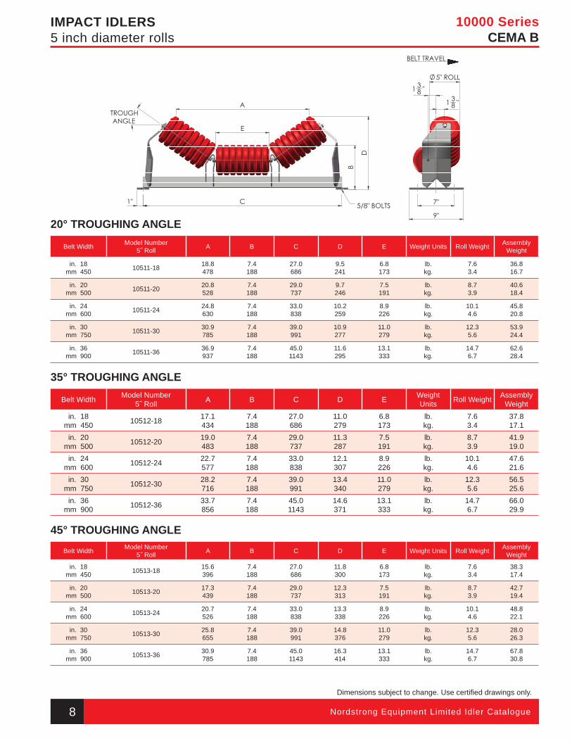
IMPACT IDLERS5 inch diameter rolls
20° TROUGHING ANGLE
Belt Width Model Number5˝ Roll A B C D E Weight Units Roll Weight Assembly
Weight
in. 18mm 450 10511-18 18.8
4787.4 188
27.0686
9.5 241
6.8173
lb.kg.
7.63.4
36.816.7
in. 20mm 500 10511-20 20.8
5287.4188
29.0737
9.7246
7.5191
lb.kg.
8.73.9
40.618.4
in. 24mm 600 10511-24 24.8
6307.4188
33.0838
10.2259
8.9226
lb.kg.
10.14.6
45.820.8
in. 30mm 750 10511-30 30.9
7857.4188
39.0991
10.9277
11.0279
lb.kg.
12.35.6
53.924.4
in. 36mm 900 10511-36 36.9
9377.4188
45.01143
11.6295
13.1333
lb.kg.
14.76.7
62.628.4
35° TROUGHING ANGLE
Belt Width Model Number5˝ Roll A B C D E Weight
Units Roll Weight Assembly Weight
in. 18mm 450 10512-18 17.1
4347.4 188
27.0686
11.0279
6.8173
lb.kg.
7.63.4
37.817.1
in. 20mm 500 10512-20 19.0
4837.4188
29.0737
11.3287
7.5191
lb.kg.
8.73.9
41.919.0
in. 24mm 600 10512-24 22.7
5777.4188
33.0838
12.1307
8.9226
lb.kg.
10.14.6
47.621.6
in. 30mm 750 10512-30 28.2
7167.4188
39.0991
13.4340
11.0279
lb.kg.
12.35.6
56.525.6
in. 36mm 900 10512-36 33.7
8567.4188
45.01143
14.6371
13.1333
lb.kg.
14.76.7
66.029.9
45° TROUGHING ANGLEBelt Width Model Number
5˝ Roll A B C D E Weight Units Roll Weight Assembly Weight
in. 18mm 450 10513-18 15.6
3967.4 188
27.0686
11.8300
6.8173
lb.kg.
7.63.4
38.317.4
in. 20mm 500 10513-20 17.3
4397.4188
29.0737
12.3313
7.5191
lb.kg.
8.73.9
42.719.4
in. 24mm 600 10513-24 20.7
5267.4188
33.0838
13.3338
8.9226
lb.kg.
10.14.6
48.822.1
in. 30mm 750 10513-30 25.8
6557.4188
39.0991
14.8376
11.0279
lb.kg.
12.35.6
28.026.3
in. 36mm 900 10513-36 30.9
7857.4188
45.01143
16.3414
13.1333
lb.kg.
14.76.7
67.830.8
Dimensions subject to change. Use certifi ed drawings only.
8 Nordstrong Equipment Limited Idler Catalogue
10 000 Series Idler pages.indd 3 9/24/2010 1:14:15 PM
10000 SeriesCEMA B
9Nordstrong Equipment Limited Idler Catalogue
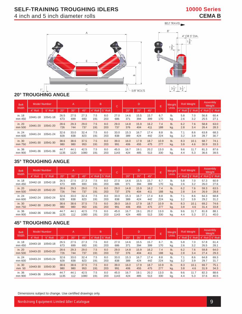
SELF-TRAINING TROUGHING IDLERS4 inch and 5 inch diameter rolls
20° TROUGHING ANGLE
Belt Width
Model Number A BC
DE Weight
UnitsRoll Weight Assembly
Weight
4˝ Roll 5˝ Roll 20° 35° 45° 4˝ Roll 5˝ Roll 20° 35° 45° 4˝ Roll 5˝ Roll 4˝ Roll 5˝ Roll
in. 18mm 450 10441-18 10541-18 26.5
67327.5699
27.3693
7.5191
8.0203
27.0686
14.6371
15.5394
15.7399
6.7170
lb.kg.
5.82.6
7.03.2
56.825.5
60.427.1
in. 20mm 500 10441-20 10541-20 28.6
72629.3744
29.0737
7.5191
8.0203
29.0737
14.8376
15.9404
16.2411
7.4188
lb.kg.
6.22.8
7.63.4
58.826.4
63.028.3
in. 24mm 600 10441-24 10541-24 32.6
82833.0838
32.4823
7.5191
8.0203
33.0838
15.3389
16.7424
17.4442
8.8224
lb.kg.
7.13.2
8.63.9
63.828.7
68.330.7
in. 30mm 750 10441-30 10541-30 38.6
98038.6980
37.5953
7.5191
8.0203
39.0991
16.0406
17.9455
18.7475
10.9277
lb.kg.
8.33.8
10.14.6
68.730.9
74.133.3
in. 36mm 900 10441-36 10541-36 44.7
113544.11120
42.51080
7.5191
8.0203
45.01143
16.7424
19.1485
20.2513
13.0330
lb.kg.
9.64.4
11.75.3
81.336.6
87.639.5
35° TROUGHING ANGLE
Belt Width
Model Number A BC
DE Weight
UnitsRoll Weight Assembly
Weight4˝ Roll 5˝ Roll 20° 35° 45° 4˝ Roll 5˝ Roll 20° 35° 45° 4˝ Roll 5˝ Roll 4˝ Roll 5˝ Roll
in. 18mm 450 10442-18 10542-18 26.5
67327.5699
27.3693
7.5191
8.0203
27.0686
14.6371
15.5394
15.7399
6.7170
lb.kg.
5.82.6
7.03.2
57.326.0
60.927.6
in. 20mm 500 10442-20 10542-20 28.6
72629.3 744
29.0737
7.5191
8.0203
29.0737
14.8376
15.9404
16.2411
7.4188
lb.kg.
6.22.8
7.63.4
59.326.9
63.528.8
in. 24mm 600 10442-24 10542-24 32.6
82833.0838
32.4823
7.5191
8.0 203
33.0838
15.3389
16.7424
17.4442
8.8224
lb.kg.
7.13.2
8.63.9
64.329.2
68.831.2
in. 30mm 750 10442-30 10542-30 38.6
98038.6980
37.5953
7.5191
8.0203
39.0991
16.0406
17.9455
18.7475
10.9277
lb.kg.
8.33.8
10.1 4.6
69.231.4
74.633.8
in. 36mm 900 10442-36 10542-36 44.7
113544.1112
42.51080
7.5191
8.0203
45.01143
16.7424
19.1485
20.2513
13.0330
lb.kg.
9.64.4
11.75.3
81.837.1
88.140.0
45° TROUGHING ANGLE
Belt Width
Model Number A BC
DE Weight
UnitsRoll Weight Assembly
Weight4˝ Roll 5˝ Roll 20° 35° 45° 4˝ Roll 5˝ Roll 20° 35° 45° 4˝ Roll 5˝ Roll 4˝ Roll 5˝ Roll
in. 18mm 450 10443-18 10543-18 26.5
67327.5699
27.3693
7.5191
8.0203
27.0686
14.6371
15.5394
15.7399
6.7170
lb.kg.
5.82.6
7.03.2
57.826.5
61.428.1
in. 20mm 500 10443-20 10543-20 28.6
72629.3 744
29.0737
7.5191
8.0203
29.0737
14.8376
15.9404
16.2411
7.4188
lb.kg.
6.22.8
7.63.4
59.827.4
64.029.3
in. 24mm 600 10443-24 10543-24 32.6
82833.0838
32.4823
7.5191
8.0 203
33.0838
15.3389
16.7424
17.4442
8.8224
lb.kg.
7.13.2
8.63.9
64.829.7
69.331.7
in. 30mm 50 10443-30 10543-30 38.6
98038.6980
37.5953
7.5191
8.0203
39.0991
16.0406
17.9455
18.7475
10.9277
lb.kg.
8.33.8
10.1 4.6
69.731.9
75.134.3
in. 36mm 900 10443-36 10543-36 44.7
113544.1112
42.51080
7.5191
8.0203
45.01143
16.7424
19.1485
20.2513
13.0330
lb.kg.
9.64.4
11.75.3
82.337.6
88.640.5
Dimensions subject to change. Use certifi ed drawings only.
10 000 Series Idler pages.indd 4 9/24/2010 1:14:16 PM
10000 SeriesCEMA B
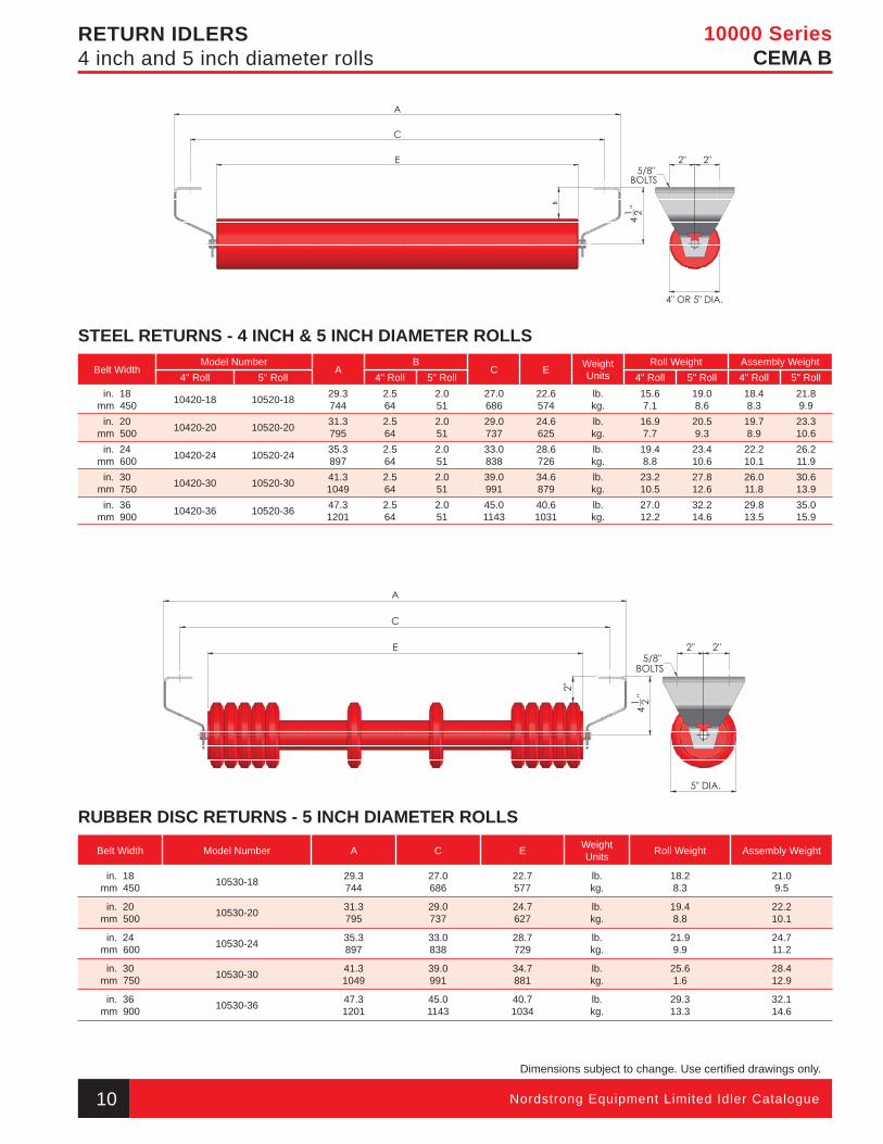
RETURN IDLERS4 inch and 5 inch diameter rolls
STEEL RETURNS - 4 INCH & 5 INCH DIAMETER ROLLS
Belt WidthModel Number
AB
C E Weight Units
Roll Weight Assembly Weight 4" Roll 5" Roll 4" Roll 5" Roll 4" Roll 5" Roll 4" Roll 5" Roll
in. 18mm 450 10420-18 10520-18 29.3
7442.564
2.051
27.0686
22.6574
lb.kg.
15.67.1
19.08.6
18.48.3
21.89.9
in. 20mm 500 10420-20 10520-20 31.3
7952.564
2.051
29.0737
24.6625
lb.kg.
16.97.7
20.59.3
19.78.9
23.310.6
in. 24mm 600 10420-24 10520-24 35.3
8972.564
2.051
33.0838
28.6726
lb.kg.
19.48.8
23.410.6
22.210.1
26.211.9
in. 30mm 750 10420-30 10520-30 41.3
10492.564
2.051
39.0991
34.6879
lb.kg.
23.210.5
27.812.6
26.011.8
30.613.9
in. 36mm 900 10420-36 10520-36 47.3
12012.564
2.051
45.01143
40.61031
lb.kg.
27.012.2
32.214.6
29.813.5
35.015.9
RUBBER DISC RETURNS - 5 INCH DIAMETER ROLLS
Belt Width Model Number A C E Weight Units Roll Weight Assembly Weight
in. 18mm 450 10530-18 29.3
74427.0686
22.7577
lb.kg.
18.28.3
21.09.5
in. 20mm 500 10530-20 31.3
79529.0737
24.7627
lb.kg.
19.48.8
22.210.1
in. 24mm 600 10530-24 35.3
89733.0838
28.7729
lb.kg.
21.99.9
24.711.2
in. 30mm 750 10530-30 41.3
104939.0991
34.7881
lb.kg.
25.61.6
28.412.9
in. 36mm 900 10530-36 47.3
120145.01143
40.71034
lb.kg.
29.313.3
32.114.6
Dimensions subject to change. Use certifi ed drawings only.
10 Nordstrong Equipment Limited Idler Catalogue
10 000 Series Idler pages.indd 5 9/24/2010 1:14:18 PM
10000 SeriesCEMA B
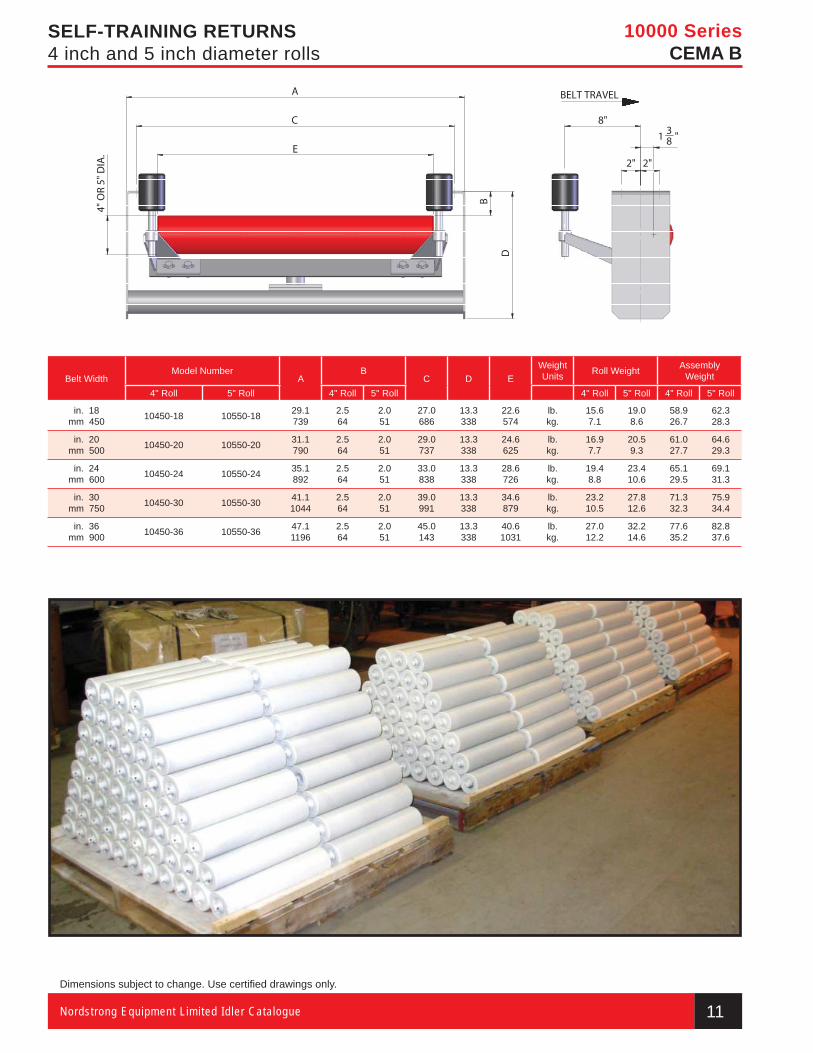
SELF-TRAINING RETURNS4 inch and 5 inch diameter rolls
Belt WidthModel Number
AB
C D EWeight Units Roll Weight Assembly
Weight
4" Roll 5" Roll 4" Roll 5" Roll 4" Roll 5" Roll 4" Roll 5" Roll
in. 18mm 450 10450-18 10550-18 29.1
7392.564
2.051
27.0686
13.3338
22.6574
lb.kg.
15.67.1
19.08.6
58.926.7
62.328.3
in. 20mm 500 10450-20 10550-20 31.1
7902.564
2.051
29.0737
13.3338
24.6625
lb.kg.
16.97.7
20.59.3
61.027.7
64.629.3
in. 24mm 600 10450-24 10550-24 35.1
8922.564
2.051
33.0838
13.3338
28.6726
lb.kg.
19.48.8
23.410.6
65.129.5
69.131.3
in. 30mm 750 10450-30 10550-30 41.1
10442.564
2.051
39.0991
13.3338
34.6879
lb.kg.
23.210.5
27.812.6
71.332.3
75.934.4
in. 36mm 900 10450-36 10550-36 47.1
11962.564
2.051
45.0143
13.3338
40.61031
lb.kg.
27.012.2
32.214.6
77.635.2
82.837.6
Dimensions subject to change. Use certifi ed drawings only.
11Nordstrong Equipment Limited Idler Catalogue
10 000 Series Idler pages.indd 6 9/24/2010 1:14:20 PM
Nordstrong Equipment Limited Idler Catalogue
Dimensions subject to change. Use certifi ed drawings only.
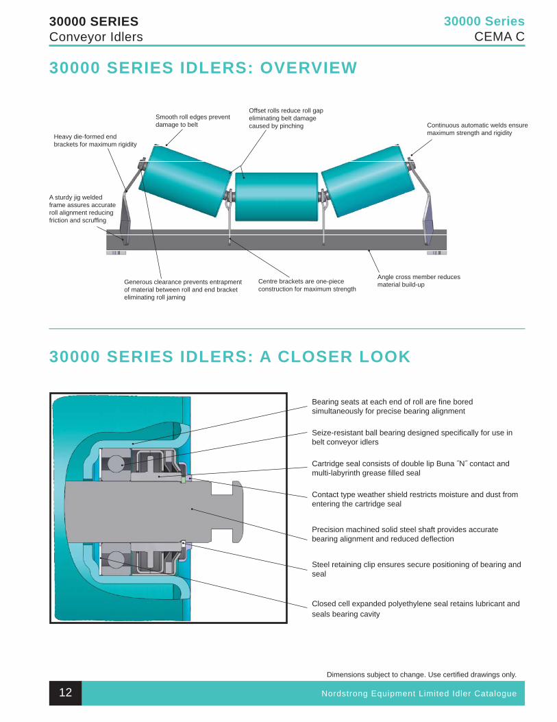
30000 SeriesCEMA C
30000 SERIESConveyor Idlers
Heavy die-formed end brackets for maximum rigidity
A sturdy jig welded frame assures accurate roll alignment reducing friction and scruffi ng
Generous clearance prevents entrapment of material between roll and end bracket eliminating roll jaming
Centre brackets are one-piece construction for maximum strength
Angle cross member reducesmaterial build-up
Continuous automatic welds ensure maximum strength and rigidity
Smooth roll edges prevent damage to belt
Offset rolls reduce roll gap eliminating belt damage caused by pinching
Bearing seats at each end of roll are fi ne bored simultaneously for precise bearing alignment
Seize-resistant ball bearing designed specifi cally for use in belt conveyor idlers
Cartridge seal consists of double lip Buna ˝N˝ contact and multi-labyrinth grease fi lled seal
Contact type weather shield restricts moisture and dust from entering the cartridge seal
Precision machined solid steel shaft provides accurate bearing alignment and reduced defl ection
Steel retaining clip ensures secure positioning of bearing and seal
Closed cell expanded polyethylene seal retains lubricant andseals bearing cavity
30000 SERIES IDLERS: A CLOSER LOOK
30000 SERIES IDLERS: OVERVIEW
12
30 000 & 35 000 Series Section.indd 11 9/24/2010 1:54:33 PM
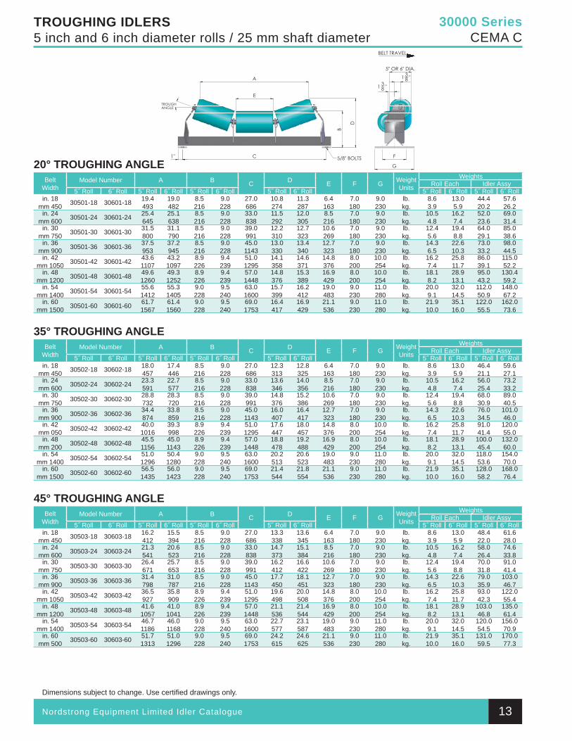
Nordstrong Equipment Limited Idler Catalogue
Dimensions subject to change. Use certifi ed drawings only.
30000 SeriesCEMA C
TROUGHING IDLERS5 inch and 6 inch diameter rolls / 25 mm shaft diameter
20° TROUGHING ANGLEBelt
WidthModel Number A B C D E F G Weight
Units
WeightsRoll Each Idler Assy
5˝ Roll 6˝ Roll 5˝ Roll 6˝ Roll 5˝ Roll 6˝ Roll 5˝ Roll 6˝ Roll 5˝ Roll 6˝ Roll 5˝ Roll 6˝ Rollin. 18
mm 450 30501-18 30601-18 19.4493
19.0482
8.5216
9.0228
27.0686
10.8274
11.3287
6.4163
7.0180
9.0230
lb.kg.
8.63.9
13.05.9
44.420.2
57.626.2
in. 24mm 600 30501-24 30601-24 25.4
64525.1638
8.5216
9.0228
33.0838
11.5292
12.0305
8.5216
7.0180
9.0230
lb.kg.
10.54.8
16.27.4
52.023.6
69.031.4
in. 30mm 750 30501-30 30601-30 31.5
80031.1790
8.5216
9.0228
39.0991
12.2310
12.7323
10.6269
7.0180
9.0230
lb.kg.
12.45.6
19.48.8
64.029.1
85.038.6
in. 36mm 900 30501-36 30601-36 37.5
95337.2945
8.5216
9.0228
45.01143
13.0330
13.4340
12.7323
7.0180
9.0230
lb.kg.
14.36.5
22.610.3
73.033.2
98.044.5
in. 42mm 1050 30501-42 30601-42 43.6
110743.21097
8.9226
9.4239
51.01295
14.1358
14.6371
14.8376
8.0200
10.0254
lb.kg.
16.27.4
25.811.7
86.039.1
115.052.2
in. 48mm 1200 30501-48 30601-48 49.6
126049.31252
8.9226
9.4239
57.01448
14.8376
15.3389
16.9429
8.0200
10.0254
lb.kg.
18.18.2
28.913.1
95.043.2
130.459.2
in. 54mm 1400 30501-54 30601-54 55.6
141255.31405
9.0228
9.5240
63.01600
15.7399
16.2412
19.0483
9.0230
11.0280
lb.kg.
20.09.1
32.014.5
112.050.9
148.067.2
in. 60mm 1500 30501-60 30601-60 61.7
156761.41560
9.0228
9.5240
69.01753
16.4417
16.9429
21.1536
9.0230
11.0280
lb.kg.
21.910.0
35.116.0
122.055.5
162.073.6
35° TROUGHING ANGLEBelt
WidthModel Number A B C D E F G Weight
Units
WeightsRoll Each Idler Assy
5˝ Roll 6˝ Roll 5˝ Roll 6˝ Roll 5˝ Roll 6˝ Roll 5˝ Roll 6˝ Roll 5˝ Roll 6˝ Roll 5˝ Roll 6˝ Rollin. 18
mm 450 30502-18 30602-18 18.0457
17.4446
8.5216
9.0228
27.0686
12.3313
12.8325
6.4163
7.0180
9.0230
lb.kg.
8.63.9
13.05.9
46.421.1
59.627.1
in. 24mm 600 30502-24 30602-24 23.3
59122.7577
8.5216
9.0228
33.0838
13.6346
14.0356
8.5216
7.0180
9.0230
lb.kg.
10.54.8
16.27.4
56.025.4
73.233.2
in. 30mm 750 30502-30 30602-30 28.8
73228.3720
8.5216
9.0228
39.0991
14.8376
15.2386
10.6269
7.0180
9.0230
lb.kg.
12.45.6
19.48.8
68.030.9
89.040.5
in. 36mm 900 30502-36 30602-36 34.4
87433.8859
8.5216
9.0228
45.01143
16.0407
16.4417
12.7323
7.0180
9.0230
lb.kg.
14.36.5
22.610.3
76.034.5
101.046.0
in. 42mm 050 30502-42 30602-42 40.0
101639.3998
8.9226
9.4239
51.01295
17.6447
18.0457
14.8376
8.0200
10.0254
lb.kg.
16.27.4
25.811.7
91.041.4
120.055.0
in. 48mm 200 30502-48 30602-48 45.5
115645.01143
8.9226
9.4239
57.01448
18.8478
19.2488
16.9429
8.0200
10.0254
lb.kg.
18.18.2
28.913.1
100.045.4
132.060.0
in. 54mm 1400 30502-54 30602-54 51.0
129650.41280
9.0228
9.5240
63.01600
20.2513
20.6523
19.0483
9.0230
11.0280
lb.kg.
20.09.1
32.014.5
118.053.6
154.070.0
in. 60mm 1500 30502-60 30602-60 56.5
143556.01423
9.0228
9.5240
69.01753
21.4544
21.8554
21.1536
9.0230
11.0280
lb.kg.
21.910.0
35.116.0
128.058.2
168.076.4
45° TROUGHING ANGLEBelt
WidthModel Number A B C D E F G Weight
Units
WeightsRoll Each Idler Assy
5˝ Roll 6˝ Roll 5˝ Roll 6˝ Roll 5˝ Roll 6˝ Roll 5˝ Roll 6˝ Roll 5˝ Roll 6˝ Roll 5˝ Roll 6˝ Rollin. 18
mm 450 30503-18 30603-18 16.2412
15.5394
8.5216
9.0228
27.0686
13.3338
13.6345
6.4163
7.0180
9.0230
lb.kg.
8.63.9
13.05.9
48.4 22.0
61.628.0
in. 24mm 600 30503-24 30603-24 21.3
54120.6523
8.5216
9.0228
33.0838
14.7373
15.1384
8.5216
7.0180
9.0230
lb.kg.
10.54.8
16.27.4
58.026.4
74.633.8
in. 30mm 750 30503-30 30603-30 26.4
67125.7653
8.5216
9.0228
39.0991
16.2412
16.6422
10.6269
7.0180
9.0230
lb.kg.
12.45.6
19.48.8
70.031.8
91.041.4
in. 36mm 900 30503-36 30603-36 31.4
79831.0787
8.5216
9.0228
45.01143
17.7450
18.1451
12.7323
7.0180
9.0230
lb.kg.
14.36.5
22.610.3
79.035.9
103.046.7
in. 42mm 1050 30503-42 30603-42 36.5
92735.8909
8.9226
9.4239
51.01295
19.6498
20.0508
14.8376
8.0200
10.0254
lb.kg.
16.27.4
25.811.7
93.042.3
122.055.4
in. 48mm 1200 30503-48 30603-48 41.6
105741.01041
8.9226
9.4239
57.01448
21.1536
21.4544
16.9429
8.0200
10.0254
lb.kg.
18.18.2
28.913.1
103.046.8
135.061.4
in. 54mm 1400 30503-54 30603-54 46.7
118646.01168
9.0228
9.5240
63.01600
22.7577
23.1587
19.0483
9.0230
11.0280
lb.kg.
20.09.1
32.014.5
120.054.5
156.070.9
in. 60mm 500 30503-60 30603-60 51.7
131351.01296
9.0228
9.5240
69.01753
24.2615
24.6625
21.1536
9.0230
11.0280
lb.kg.
21.910.0
35.116.0
131.059.5
170.077.3
13
30 000 & 35 000 Series Section.indd 12 9/24/2010 1:54:41 PM
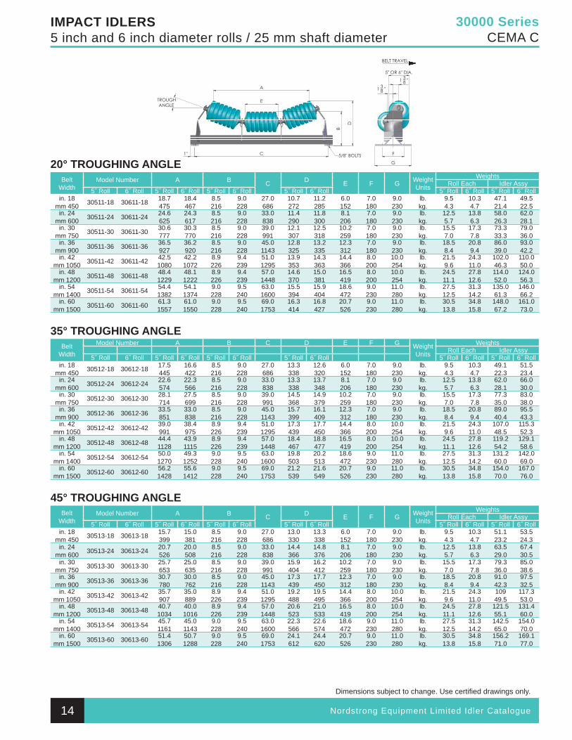
Nordstrong Equipment Limited Idler Catalogue
Dimensions subject to change. Use certifi ed drawings only.
30000 SeriesCEMA C
IMPACT IDLERS5 inch and 6 inch diameter rolls / 25 mm shaft diameter
20° TROUGHING ANGLEBelt
WidthModel Number A B C D E F G Weight
Units
WeightsRoll Each Idler Assy
5˝ Roll 6˝ Roll 5˝ Roll 6˝ Roll 5˝ Roll 6˝ Roll 5˝ Roll 6˝ Roll 5˝ Roll 6˝ Roll 5˝ Roll 6˝ Rollin. 18
mm 450 30511-18 30611-18 18.7475
18.4467
8.5216
9.0228
27.0686
10.7272
11.2285
6.0152
7.0180
9.0230
lb.kg.
9.54.3
10.34.7
47.121.4
49.522.5
in. 24mm 600 30511-24 30611-24 24.6
62524.3617
8.5216
9.0228
33.0838
11.4290
11.8300
8.1206
7.0180
9.0230
lb.kg.
12.55.7
13.86.3
58.026.3
62.028.1
in. 30mm 750 30511-30 30611-30 30.6
77730.3770
8.5216
9.0228
39.0991
12.1307
12.5318
10.2259
7.0180
9.0230
lb.kg.
15.57.0
17.37.8
73.333.3
79.036.0
in. 36mm 900 30511-36 30611-36 36.5
92736.2920
8.5216
9.0228
45.01143
12.8325
13.2335
12.3312
7.0180
9.0230
lb.kg.
18.58.4
20.89.4
86.039.0
93.042.2
in. 42mm 1050 30511-42 30611-42 42.5
108042.21072
8.9226
9.4239
51.01295
13.9353
14.3363
14.4366
8.0200
10.0254
lb.kg.
21.59.6
24.311.0
102.046.3
110.050.0
in. 48mm 1200 30511-48 30611-48 48.4
122948.11222
8.9226
9.4239
57.01448
14.6370
15.0381
16.5419
8.0200
10.0254
lb.kg.
24.511.1
27.812.6
114.052.0
124.056.3
in. 54mm 1400 30511-54 30611-54 54.4
138254.11374
9.0228
9.5240
63.01600
15.5394
15.9404
18.6472
9.0230
11.0280
lb.kg.
27.512.5
31.314.2
135.061.3
146.066.2
in. 60mm 1500 30511-60 30611-60 61.3
155761.01550
9.0228
9.5240
69.01753
16.3414
16.8427
20.7526
9.0230
11.0280
lb.kg.
30.513.8
34.815.8
148.067.2
161.073.0
35° TROUGHING ANGLEBelt
Width
Model Number A B C D E F G Weight Units
WeightsRoll Each Idler Assy
5˝ Roll 6˝ Roll 5˝ Roll 6˝ Roll 5˝ Roll 6˝ Roll 5˝ Roll 6˝ Roll 5˝ Roll 6˝ Roll 5˝ Roll 6˝ Rollin. 18
mm 450 30512-18 30612-18 17.5445
16.6422
8.5216
9.0228
27.0686
13.3338
12.6320
6.0152
7.0180
9.0230
lb.kg.
9.54.3
10.34.7
49.122.3
51.523.4
in. 24mm 600 30512-24 30612-24 22.6
57422.3566
8.5216
9.0228
33.0838
13.3338
13.7348
8.1206
7.0180
9.0230
lb.kg.
12.55.7
13.86.3
62.028.1
66.030.0
in. 30mm 750 30512-30 30612-30 28.1
71427.5699
8.5216
9.0228
39.0991
14.5368
14.9379
10.2259
7.0180
9.0230
lb.kg.
15.57.0
17.37.8
77.335.0
83.038.0
in. 36mm 900 30512-36 30612-36 33.5
85133.0838
8.5216
9.0228
45.01143
15.7399
16.1409
12.3312
7.0180
9.0230
lb.kg.
18.58.4
20.89.4
89.040.4
95.543.3
in. 42mm 1050 30512-42 30612-42 39.0
99138.4975
8.9226
9.4239
51.01295
17.3439
17.7450
14.4366
8.0200
10.0254
lb.kg.
21.59.6
24.311.0
107.048.5
115.352.3
in. 48mm 1200 30512-48 30612-48 44.4
112843.91115
8.9226
9.4239
57.01448
18.4467
18.8477
16.5419
8.0200
10.0254
lb.kg.
24.511.1
27.812.6
119.254.2
129.158.6
in. 54mm 1400 30512-54 30612-54 50.0
127049.31252
9.0228
9.5240
63.01600
19.8503
20.2513
18.6472
9.0230
11.0280
lb.kg.
27.512.5
31.314.2
131.260.0
142.069.0
in. 60mm 1500 30512-60 30612-60 56.2
142855.61412
9.0228
9.5240
69.01753
21.2539
21.6549
20.7526
9.0230
11.0280
lb.kg.
30.513.8
34.815.8
154.070.0
167.076.0
45° TROUGHING ANGLEBelt
WidthModel Number A B C D E F G Weight
Units
WeightsRoll Each Idler Assy
5˝ Roll 6˝ Roll 5˝ Roll 6˝ Roll 5˝ Roll 6˝ Roll 5˝ Roll 6˝ Roll 5˝ Roll 6˝ Roll 5˝ Roll 6˝ Rollin. 18
mm 450 30513-18 30613-18 15.7399
15.0381
8.5216
9.0228
27.0686
13.0330
13.3338
6.0152
7.0180
9.0230
lb.kg.
9.54.3
10.34.7
51.123.2
53.524.3
in. 24mm 600 30513-24 30613-24 20.7
52620.0508
8.5216
9.0228
33.0838
14.4366
14.8376
8.1206
7.0180
9.0230
lb.kg.
12.55.7
13.86.3
63.529.0
67.430.5
in. 30mm 750 30513-30 30613-30 25.7
65325.0635
8.5216
9.0228
39.0991
15.9404
16.2412
10.2259
7.0180
9.0230
lb.kg.
15.57.0
17.37.8
79.336.0
85.038.6
in. 36mm 900 30513-36 30613-36 30.7
78030.0762
8.5216
9.0228
45.01143
17.3439
17.7450
12.3312
7.0180
9.0230
lb.kg.
18.58.4
20.89.4
91.042.3
97.532.5
in. 42mm 1050 30513-42 30613-42 35.7
90735.0889
8.9226
9.4239
51.01295
19.2488
19.5495
14.4366
8.0200
10.0254
lb.kg.
21.59.6
24.311.0
10949.5
117.353.0
in. 48mm 1200 30513-48 30613-48 40.7
103440.01016
8.9226
9.4239
57.01448
20.6523
21.0533
16.5419
8.0200
10.0254
lb.kg.
24.511.1
27.812.6
121.555.1
131.460.0
in. 54mm 1400 30513-54 30613-54 45.7
116145.01143
9.0228
9.5240
63.01600
22.3566
22.6574
18.6472
9.0230
11.0280
lb.kg.
27.512.5
31.314.2
142.565.0
154.070.0
in. 60mm 1500 30513-60 30613-60 51.4
130650.71288
9.0228
9.5240
69.01753
24.1612
24.4620
20.7526
9.0230
11.0280
lb.kg.
30.513.8
34.815.8
156.271.0
169.177.0
14
30 000 & 35 000 Series Section.indd 13 9/24/2010 1:54:43 PM
Nordstrong Equipment Limited Idler Catalogue
Dimensions subject to change. Use certifi ed drawings only.
30000 SeriesCEMA C
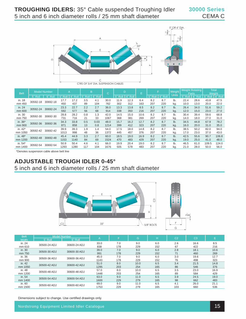
TROUGHING IDLERS: 35° Cable suspended Troughing Idler5 inch and 6 inch diameter rolls / 25 mm shaft diameter
ADJUSTABLE TROUGH IDLER 0-45°5 inch and 6 inch diameter rolls / 25 mm shaft diameter
Belt Model Number A B C D E F Weight Units
Weight Rotating Parts
TotalWeight
5˝ Roll 6˝ Roll 5˝ Roll 6˝ Roll 5˝ Roll 6˝ Roll 5˝ Roll 6˝ Roll 5˝ Roll 6˝ Roll 5˝ Roll 6˝ Roll 5˝ Roll 6˝ Rollin. 18
mm 450 30592-18 30692-18 17.7450
17.2437
3.589
4.1104
30.0762
11.9302
12.3312
6.4163
8.2207
8.7220
lb.kg.
22.410.0
28.613.0
43.820.0
47.522.0
in. 24mm 600 30592-24 30692-24 23.3
59222.7577
2.256
2.768
36.0914
13.3338
13.8350
8.5216
8.2207
8.7220
lb.kg.
26.412.0
34.015.0
51.623.0
59.227.0
in. 30mm 750 30592-30 30692-30 28.8
73128.2716
0.821
1.333
42.01067
14.5368
15.0381
10.6269
8.2207
8.7220
lb.kg.
30.414.0
39.418.0
59.627.0
68.831.0
in. 36*mm 900 30592-36 30692-36 34.3
87133.8858
0.513
0.030.8
48.01214
15.7399
16.2412
12.7323
8.2207
8.7220
lb.kg.
34.516.0
44.820.0
67.931.0
78.235.0
in. 42*mm 1050 30592-42 30692-42 39.9
101339.3998
1.948
1.436
54.01372
17.5445
18.0457
14.8376
8.2207
8.7220
lb.kg.
38.517.0
50.223.0
82.037.0
94.043.0
in. 48*mm 1200 30592-48 30692-48 45.4
115344.91140
3.384
2.769
60.01524
18.5470
19.0483
16.9429
8.2207
8.7220
lb.kg.
42.519.0
55.625.0
90.741.0
106.848.0
in. 54*mm 1400 30592-54 30692-54 50.9
129350.41280
4.6117
4.1104
66.01676
19.9505
20.4578
19.0483
8.2207
8.7220
lb.kg.
46.521.0
61.028.0
109.550.0
124.056.0
*Denotes suspension cable above belt line
BeltWidth
Model Number A F G H C2 C3 E5˝ Roll 6˝ Rollin. 24
mm 610 30500-24 ADJ 30600-24 ADJ 33.0838
7.0178
9.0229
6.0152
2.667
16.6422
8.5216
in. 30mm 750 30500-30 ADJ 30600-30 ADJ 39.0
9917.0178
9.0229
6.0152
2.871
18.1460
10.6269
in. 36mm 900 30500-36 ADJ 30600-36 ADJ 45.0
11437.0178
9.0229
6.0152
3.076
19.6498
12.7323
in. 42mm 1050 30500-42 ADJ 30600-42 ADJ 51.0
12958.0203
10.0254
6.5165
3.486
21.5546
14.8376
in. 48mm 1200 30500-48 ADJ 30600-48 ADJ 57.0
14488.0203
10.0254
6.5165
3.589
23.0584
16.9429
in. 54mm 1400 30500-54 ADJ 30600-54 ADJ 63.0
16009.0229
11.0279
6.5165
3.998
24.5662
19.0483
in. 60mm 1500 30500-60 ADJ 30600-60 ADJ 69.0
17539.0229
11.0279
6.5165
4.1103
26.0660
21.1536
15
30 000 & 35 000 Series Section.indd 14 9/24/2010 1:54:45 PM
Nordstrong Equipment Limited Idler Catalogue
Dimensions subject to change. Use certifi ed drawings only.
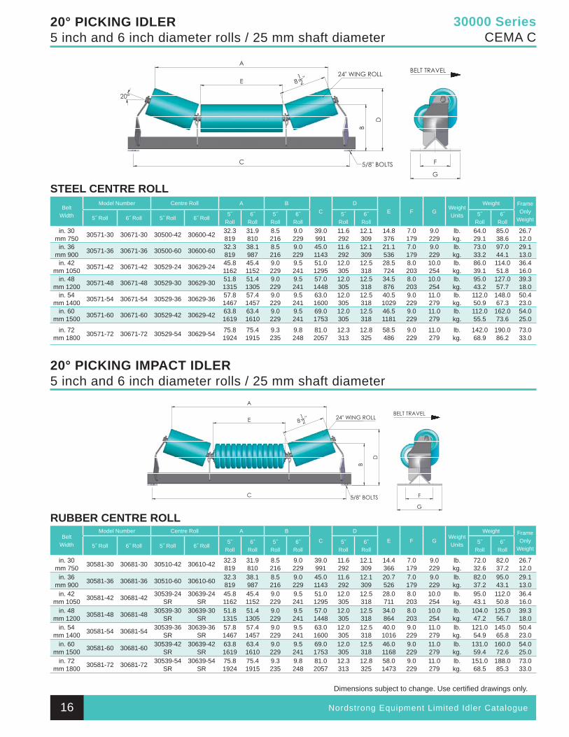
30000 SeriesCEMA C
20° PICKING IDLER5 inch and 6 inch diameter rolls / 25 mm shaft diameter
20° PICKING IMPACT IDLER5 inch and 6 inch diameter rolls / 25 mm shaft diameter
STEEL CENTRE ROLLBelt
Width
Model Number Centre Roll A BC
DE F G
Weight Units
Weight Frame Only
Weight5˝ Roll 6˝ Roll 5˝ Roll 6˝ Roll5˝
Roll6˝
Roll5˝
Roll6˝
Roll5˝
Roll6˝
Roll5˝
Roll6˝
Rollin. 30
mm 750 30571-30 30671-30 30500-42 30600-42 32.3819
31.9810
8.5216
9.0229
39.0991
11.6292
12.1309
14.8376
7.0179
9.0229
lb.kg.
64.029.1
85.038.6
26.712.0
in. 36mm 900 30571-36 30671-36 30500-60 30600-60 32.3
81938.1987
8.5216
9.0229
45.01143
11.6292
12.1309
21.1536
7.0179
9.0229
lb.kg.
73.033.2
97.044.1
29.113.0
in. 42mm 1050 30571-42 30671-42 30529-24 30629-24 45.8
116245.41152
9.0229
9.5241
51.01295
12.0305
12.5318
28.5724
8.0203
10.0254
lb.kg.
86.039.1
114.051.8
36.416.0
in. 48mm 1200 30571-48 30671-48 30529-30 30629-30 51.8
131551.41305
9.0229
9.5241
57.01448
12.0305
12.5318
34.5876
8.0203
10.0254
lb.kg.
95.043.2
127.057.7
39.318.0
in. 54mm 1400 30571-54 30671-54 30529-36 30629-36 57.8
146757.41457
9.0229
9.5241
63.01600
12.0305
12.5318
40.51029
9.0229
11.0279
lb.kg.
112.050.9
148.067.3
50.423.0
in. 60mm 1500 30571-60 30671-60 30529-42 30629-42 63.8
161963.41610
9.0229
9.5241
69.01753
12.0305
12.5318
46.51181
9.0229
11.0279
lb.kg.
112.055.5
162.073.6
54.025.0
in. 72mm 1800 30571-72 30671-72 30529-54 30629-54 75.8
192475.41915
9.3235
9.8248
81.02057
12.3313
12.8325
58.5486
9.0229
11.0279
lb.kg.
142.068.9
190.086.2
73.033.0
RUBBER CENTRE ROLLBelt
Width
Model Number Centre Roll A B
C
D
E F GWeight Units
Weight Frame Only
Weight5˝ Roll 6˝ Roll 5˝ Roll 6˝ Roll5˝
Roll6˝
Roll5˝
Roll6˝
Roll5˝
Roll6˝
Roll5˝
Roll6˝
Roll
in. 30mm 750 30581-30 30681-30 30510-42 30610-42 32.3
81931.9810
8.5216
9.0229
39.0991
11.6292
12.1309
14.4366
7.0179
9.0229
lb.kg.
72.032.6
82.037.2
26.712.0
in. 36mm 900 30581-36 30681-36 30510-60 30610-60 32.3
81938.1987
8.5216
9.0229
45.01143
11.6292
12.1309
20.7526
7.0179
9.0229
lb.kg.
82.037.2
95.043.1
29.113.0
in. 42mm 1050 30581-42 30681-42 30539-24
SR30639-24
SR45.81162
45.41152
9.0229
9.5241
51.01295
12.0305
12.5318
28.0711
8.0203
10.0254
lb.kg.
95.043.1
112.050.8
36.416.0
in. 48mm 1200 30581-48 30681-48 30539-30
SR30639-30
SR51.81315
51.41305
9.0229
9.5241
57.01448
12.0305
12.5318
34.0864
8.0203
10.0254
lb.kg.
104.047.2
125.056.7
39.318.0
in. 54mm 1400 30581-54 30681-54 30539-36
SR30639-36
SR57.81467
57.41457
9.0229
9.5241
63.01600
12.0305
12.5318
40.01016
9.0229
11.0279
lb.kg.
121.054.9
145.065.8
50.423.0
in. 60mm 1500 30581-60 30681-60 30539-42
SR30639-42
SR63.81619
63.41610
9.0229
9.5241
69.01753
12.0305
12.5318
46.01168
9.0229
11.0279
lb.kg.
131.059.4
160.072.6
54.025.0
in. 72mm 1800 30581-72 30681-72 30539-54
SR30639-54
SR75.81924
75.41915
9.3235
9.8248
81.02057
12.3313
12.8325
58.01473
9.0229
11.0279
lb.kg.
151.068.5
188.085.3
73.0 33.0
16
30 000 & 35 000 Series Section.indd 15 9/24/2010 1:54:48 PM
Nordstrong Equipment Limited Idler Catalogue
Dimensions subject to change. Use certifi ed drawings only.
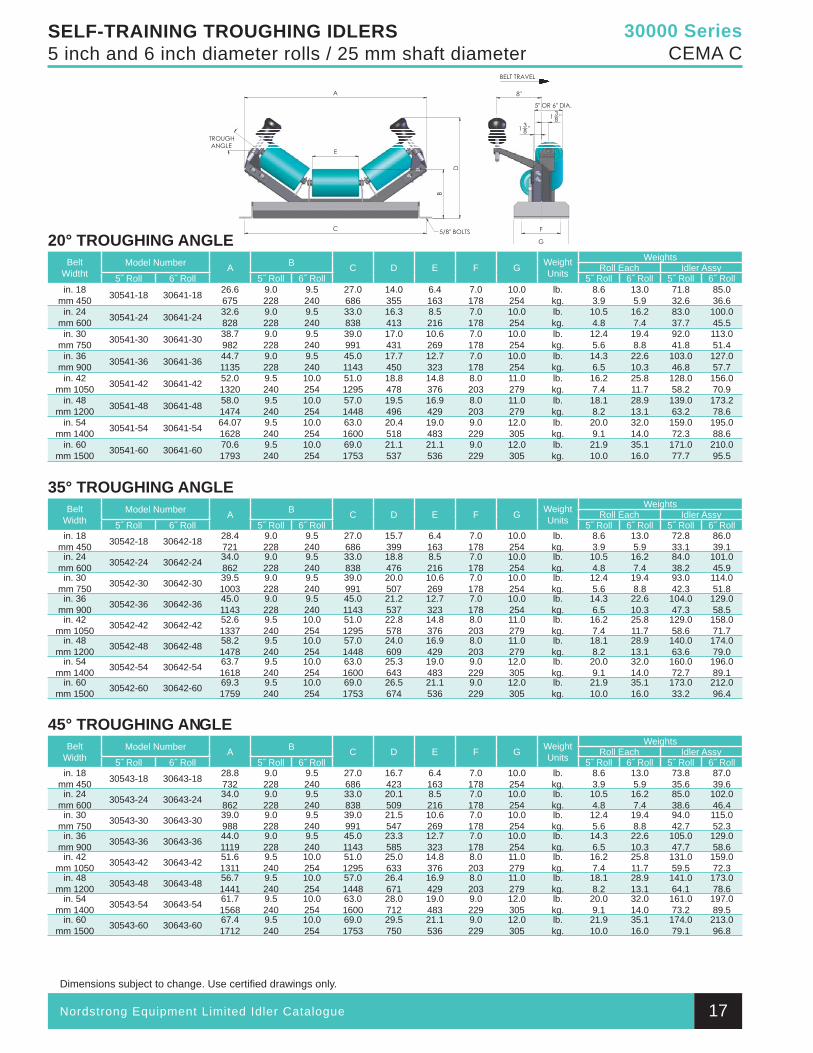
30000 SeriesCEMA C
SELF-TRAINING TROUGHING IDLERS5 inch and 6 inch diameter rolls / 25 mm shaft diameter
20° TROUGHING ANGLEBelt
WidthtModel Number A B C D E F G Weight
Units
WeightsRoll Each Idler Assy
5˝ Roll 6˝ Roll 5˝ Roll 6˝ Roll 5˝ Roll 6˝ Roll 5˝ Roll 6˝ Rollin. 18
mm 450 30541-18 30641-18 26.6675
9.0228
9.5240
27.0686
14.0355
6.4163
7.0178
10.0254
lb.kg.
8.63.9
13.05.9
71.832.6
85.036.6
in. 24mm 600 30541-24 30641-24 32.6
8289.0228
9.5240
33.0838
16.3413
8.5216
7.0178
10.0254
lb.kg.
10.54.8
16.27.4
83.037.7
100.045.5
in. 30mm 750 30541-30 30641-30 38.7
9829.0228
9.5240
39.0991
17.0431
10.6269
7.0178
10.0254
lb.kg.
12.45.6
19.48.8
92.041.8
113.051.4
in. 36mm 900 30541-36 30641-36 44.7
11359.0228
9.5240
45.01143
17.7450
12.7323
7.0178
10.0254
lb.kg.
14.36.5
22.610.3
103.046.8
127.057.7
in. 42mm 1050 30541-42 30641-42 52.0
13209.5240
10.0254
51.01295
18.8478
14.8376
8.0203
11.0279
lb.kg.
16.27.4
25.811.7
128.058.2
156.070.9
in. 48mm 1200 30541-48 30641-48 58.0
14749.5240
10.0254
57.01448
19.5496
16.9429
8.0203
11.0279
lb.kg.
18.18.2
28.913.1
139.063.2
173.278.6
in. 54mm 1400 30541-54 30641-54 64.07
16289.5240
10.0254
63.01600
20.4518
19.0483
9.0229
12.0305
lb.kg.
20.09.1
32.014.0
159.072.3
195.088.6
in. 60mm 1500 30541-60 30641-60 70.6
17939.5240
10.0254
69.01753
21.1537
21.1536
9.0229
12.0305
lb.kg.
21.910.0
35.116.0
171.077.7
210.095.5
35° TROUGHING ANGLEBelt
WidthModel Number A B C D E F G Weight
Units
WeightsRoll Each Idler Assy
5˝ Roll 6˝ Roll 5˝ Roll 6˝ Roll 5˝ Roll 6˝ Roll 5˝ Roll 6˝ Rollin. 18
mm 450 30542-18 30642-18 28.4721
9.0228
9.5240
27.0686
15.7399
6.4163
7.0178
10.0254
lb.kg.
8.63.9
13.05.9
72.833.1
86.039.1
in. 24mm 600 30542-24 30642-24 34.0
8629.0228
9.5240
33.0838
18.8476
8.5216
7.0178
10.0254
lb.kg.
10.54.8
16.27.4
84.038.2
101.045.9
in. 30mm 750 30542-30 30642-30 39.5
10039.0228
9.5240
39.0991
20.0507
10.6269
7.0178
10.0254
lb.kg.
12.45.6
19.48.8
93.042.3
114.051.8
in. 36mm 900 30542-36 30642-36 45.0
11439.0228
9.5240
45.01143
21.2537
12.7323
7.0178
10.0254
lb.kg.
14.36.5
22.610.3
104.047.3
129.058.5
in. 42mm 1050 30542-42 30642-42 52.6
13379.5240
10.0254
51.01295
22.8578
14.8376
8.0203
11.0279
lb.kg.
16.27.4
25.811.7
129.058.6
158.071.7
in. 48mm 1200 30542-48 30642-48 58.2
14789.5240
10.0254
57.01448
24.0609
16.9429
8.0203
11.0279
lb.kg.
18.18.2
28.913.1
140.063.6
174.079.0
in. 54mm 1400 30542-54 30642-54 63.7
16189.5240
10.0254
63.01600
25.3643
19.0483
9.0229
12.0305
lb.kg.
20.09.1
32.014.0
160.072.7
196.089.1
in. 60mm 1500 30542-60 30642-60 69.3
17599.5240
10.0254
69.01753
26.5674
21.1536
9.0229
12.0305
lb.kg.
21.910.0
35.116.0
173.033.2
212.096.4
45° TROUGHING ANGLEBelt
WidthModel Number A B C D E F G Weight
Units
WeightsRoll Each Idler Assy
5˝ Roll 6˝ Roll 5˝ Roll 6˝ Roll 5˝ Roll 6˝ Roll 5˝ Roll 6˝ Rollin. 18
mm 450 30543-18 30643-18 28.8732
9.0228
9.5240
27.0686
16.7423
6.4163
7.0178
10.0254
lb.kg.
8.63.9
13.05.9
73.835.6
87.039.6
in. 24mm 600 30543-24 30643-24 34.0
8629.0228
9.5240
33.0838
20.1509
8.5216
7.0178
10.0254
lb.kg.
10.54.8
16.27.4
85.038.6
102.046.4
in. 30mm 750 30543-30 30643-30 39.0
9889.0228
9.5240
39.0991
21.5547
10.6269
7.0178
10.0254
lb.kg.
12.45.6
19.48.8
94.042.7
115.052.3
in. 36mm 900 30543-36 30643-36 44.0
11199.0228
9.5240
45.01143
23.3585
12.7323
7.0178
10.0254
lb.kg.
14.36.5
22.610.3
105.047.7
129.058.6
in. 42mm 1050 30543-42 30643-42 51.6
13119.5240
10.0254
51.01295
25.0633
14.8376
8.0203
11.0279
lb.kg.
16.27.4
25.811.7
131.059.5
159.072.3
in. 48mm 1200 30543-48 30643-48 56.7
14419.5240
10.0254
57.01448
26.4671
16.9429
8.0203
11.0279
lb.kg.
18.18.2
28.913.1
141.064.1
173.078.6
in. 54mm 1400 30543-54 30643-54 61.7
15689.5240
10.0254
63.01600
28.0712
19.0483
9.0229
12.0305
lb.kg.
20.09.1
32.014.0
161.073.2
197.089.5
in. 60mm 1500 30543-60 30643-60 67.4
17129.5240
10.0254
69.01753
29.5750
21.1536
9.0229
12.0305
lb.kg.
21.910.0
35.116.0
174.079.1
213.096.8
17
30 000 & 35 000 Series Section.indd 16 9/24/2010 1:54:51 PM
Nordstrong Equipment Limited Idler Catalogue
Dimensions subject to change. Use certifi ed drawings only.
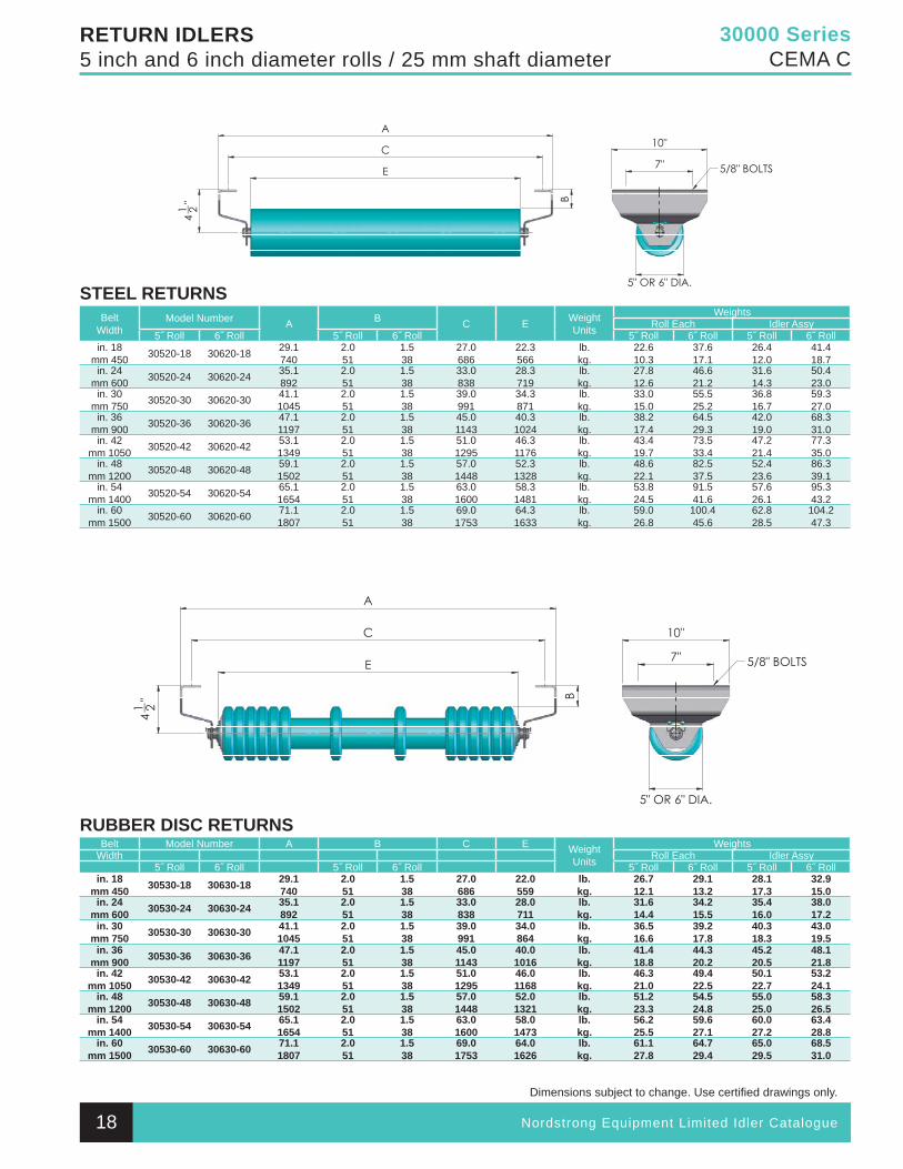
30000 SeriesCEMA C
RETURN IDLERS5 inch and 6 inch diameter rolls / 25 mm shaft diameter
STEEL RETURNSBelt
WidthModel Number A B C E Weight
Units
WeightsRoll Each Idler Assy
5˝ Roll 6˝ Roll 5˝ Roll 6˝ Roll 5˝ Roll 6˝ Roll 5˝ Roll 6˝ Rollin. 18
mm 450 30520-18 30620-18 29.1740
2.051
1.538
27.0686
22.3566
lb.kg.
22.610.3
37.617.1
26.412.0
41.418.7
in. 24mm 600 30520-24 30620-24 35.1
8922.051
1.538
33.0838
28.3719
lb.kg.
27.812.6
46.621.2
31.614.3
50.423.0
in. 30mm 750 30520-30 30620-30 41.1
10452.051
1.538
39.0991
34.3871
lb.kg.
33.015.0
55.525.2
36.816.7
59.327.0
in. 36mm 900 30520-36 30620-36 47.1
11972.051
1.538
45.01143
40.31024
lb.kg.
38.217.4
64.529.3
42.019.0
68.331.0
in. 42mm 1050 30520-42 30620-42 53.1
13492.051
1.538
51.01295
46.31176
lb.kg.
43.419.7
73.533.4
47.221.4
77.335.0
in. 48mm 1200 30520-48 30620-48 59.1
15022.051
1.538
57.01448
52.31328
lb.kg.
48.622.1
82.537.5
52.423.6
86.339.1
in. 54mm 1400 30520-54 30620-54 65.1
16542.051
1.538
63.01600
58.31481
lb.kg.
53.824.5
91.541.6
57.626.1
95.343.2
in. 60mm 1500 30520-60 30620-60 71.1
18072.051
1.538
69.01753
64.31633
lb.kg.
59.026.8
100.445.6
62.828.5
104.247.3
RUBBER DISC RETURNSBelt Model Number A B C E Weight
Units
WeightsWidth Roll Each Idler Assy
5˝ Roll 6˝ Roll 5˝ Roll 6˝ Roll 5˝ Roll 6˝ Roll 5˝ Roll 6˝ Rollin. 18
mm 450 30530-18 30630-18 29.1740
2.051
1.538
27.0686
22.0559
lb.kg.
26.712.1
29.113.2
28.117.3
32.915.0
in. 24mm 600 30530-24 30630-24 35.1
8922.051
1.538
33.0838
28.0711
lb.kg.
31.614.4
34.215.5
35.416.0
38.017.2
in. 30mm 750 30530-30 30630-30 41.1
10452.051
1.538
39.0991
34.0864
lb.kg.
36.516.6
39.217.8
40.318.3
43.019.5
in. 36mm 900 30530-36 30630-36 47.1
11972.051
1.538
45.01143
40.01016
lb.kg.
41.418.8
44.320.2
45.220.5
48.121.8
in. 42mm 1050 30530-42 30630-42 53.1
13492.051
1.538
51.01295
46.01168
lb.kg.
46.321.0
49.422.5
50.122.7
53.224.1
in. 48mm 1200 30530-48 30630-48 59.1
15022.051
1.538
57.01448
52.01321
lb.kg.
51.223.3
54.524.8
55.025.0
58.326.5
in. 54mm 1400 30530-54 30630-54 65.1
16542.051
1.538
63.01600
58.01473
lb.kg.
56.225.5
59.627.1
60.027.2
63.428.8
in. 60mm 1500 30530-60 30630-60 71.1
18072.051
1.538
69.01753
64.01626
lb.kg.
61.127.8
64.729.4
65.029.5
68.531.0
18
30 000 & 35 000 Series Section.indd 17 9/24/2010 1:54:53 PM
Nordstrong Equipment Limited Idler Catalogue
Dimensions subject to change. Use certifi ed drawings only.
30000 SeriesCEMA C
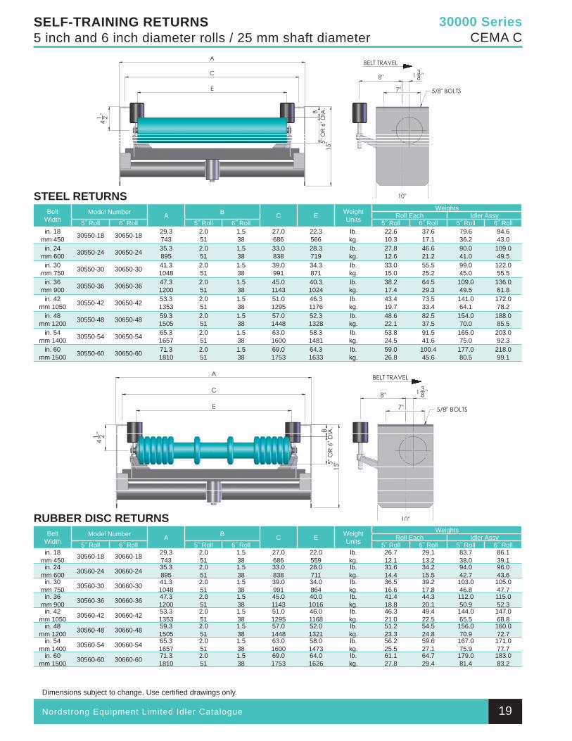
SELF-TRAINING RETURNS5 inch and 6 inch diameter rolls / 25 mm shaft diameter
STEEL RETURNSBelt
WidthModel Number A B C E Weight
Units
WeightsRoll Each Idler Assy
5˝ Roll 6˝ Roll 5˝ Roll 6˝ Roll 5˝ Roll 6˝ Roll 5˝ Roll 6˝ Rollin. 18
mm 450 30550-18 30650-18 29.3743
2.051
1.538
27.0686
22.3566
lb.kg.
22.610.3
37.617.1
79.636.2
94.643.0
in. 24mm 600 30550-24 30650-24 35.3
8952.051
1.538
33.0838
28.3719
lb.kg.
27.812.6
46.621.2
90.041.0
109.049.5
in. 30mm 750 30550-30 30650-30 41.3
10482.051
1.538
39.0991
34.3871
lb.kg.
33.015.0
55.525.2
99.045.0
122.055.5
in. 36mm 900 30550-36 30650-36 47.3
12002.051
1.538
45.01143
40.31024
lb.kg.
38.217.4
64.529.3
109.049.5
136.061.8
in. 42mm 1050 30550-42 30650-42 53.3
13532.051
1.538
51.01295
46.31176
lb.kg.
43.419.7
73.533.4
141.064.1
172.078.2
in. 48mm 1200 30550-48 30650-48 59.3
15052.051
1.538
57.01448
52.31328
lb.kg.
48.622.1
82.537.5
154.070.0
188.085.5
in. 54mm 1400 30550-54 30650-54 65.3
16572.051
1.538
63.01600
58.31481
lb.kg.
53.824.5
91.541.6
165.075.0
203.092.3
in. 60mm 1500 30550-60 30650-60 71.3
18102.051
1.538
69.01753
64.31633
lb.kg.
59.026.8
100.445.6
177.080.5
218.099.1
RUBBER DISC RETURNSBelt
WidthModel Number A B C E Weight
Units
WeightsRoll Each Idler Assy
5˝ Roll 6˝ Roll 5˝ Roll 6˝ Roll 5˝ Roll 6˝ Roll 5˝ Roll 6˝ Rollin. 18
mm 450 30560-18 30660-18 29.3743
2.051
1.538
27.0686
22.0559
lb.kg.
26.712.1
29.113.2
83.738.0
86.139.1
in. 24mm 600 30560-24 30660-24 35.3
8952.051
1.538
33.0838
28.0711
lb.kg.
31.614.4
34.215.5
94.042.7
96.043.6
in. 30mm 750 30560-30 30660-30 41.3
10482.051
1.538
39.0991
34.0864
lb.kg.
36.516.6
39.217.8
103.046.8
105.047.7
in. 36mm 900 30560-36 30660-36 47.3
12002.051
1.538
45.01143
40.01016
lb.kg.
41.418.8
44.320.1
112.050.9
115.052.3
in. 42mm 1050 30560-42 30660-42 53.3
13532.051
1.538
51.01295
46.01168
lb.kg.
46.321.0
49.422.5
144.065.5
147.068.8
in. 48mm 1200 30560-48 30660-48 59.3
15052.051
1.538
57.01448
52.01321
lb.kg.
51.223.3
54.524.8
156.070.9
160.072.7
in. 54mm 1400 30560-54 30660-54 65.3
16572.051
1.538
63.01600
58.01473
lb.kg.
56.225.5
59.627.1
167.075.9
171.077.7
in. 60mm 1500 30560-60 30660-60 71.3
18102.051
1.538
69.01753
64.01626
lb.kg.
61.127.8
64.729.4
179.081.4
183.083.2
19
30 000 & 35 000 Series Section.indd 18 9/24/2010 1:54:55 PM
Nordstrong Equipment Limited Idler Catalogue
Dimensions subject to change. Use certifi ed drawings only.
30000 SeriesCEMA C
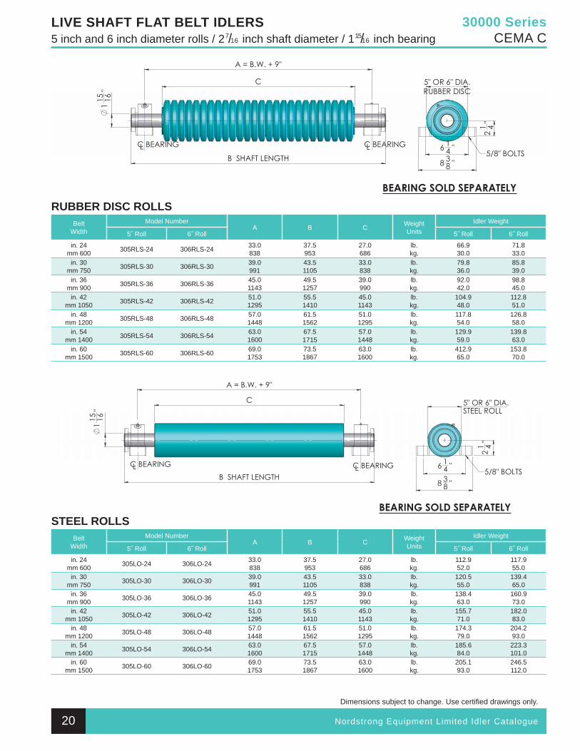
LIVE SHAFT FLAT BELT IDLERS5 inch and 6 inch diameter rolls / 27/16 inch shaft diameter / 115/16 inch bearing
STEEL ROLLSBelt
WidthModel Number
A B C WeightUnits
Idler Weight
5˝ Roll 6˝ Roll 5˝ Roll 6˝ Roll
in. 24mm 600 305LO-24 306LO-24 33.0
83837.5953
27.0686
lb.kg.
112.952.0
117.955.0
in. 30mm 750 305LO-30 306LO-30 39.0
99143.51105
33.0838
lb.kg.
120.555.0
139.465.0
in. 36mm 900 305LO-36 306LO-36 45.0
114349.51257
39.0990
lb.kg.
138.463.0
160.973.0
in. 42mm 1050 305LO-42 306LO-42 51.0
129555.51410
45.01143
lb.kg.
155.771.0
182.083.0
in. 48mm 1200 305LO-48 306LO-48 57.0
144861.51562
51.01295
lb.kg.
174.379.0
204.293.0
in. 54mm 1400 305LO-54 306LO-54 63.0
160067.51715
57.01448
lb.kg.
185.684.0
223.3101.0
in. 60mm 1500 305LO-60 306LO-60 69.0
175373.51867
63.01600
lb.kg.
205.193.0
246.5112.0
RUBBER DISC ROLLSBelt
WidthModel Number
A B C WeightUnits
Idler Weight
5˝ Roll 6˝ Roll 5˝ Roll 6˝ Roll
in. 24mm 600 305RLS-24 306RLS-24 33.0
83837.5953
27.0686
lb.kg.
66.930.0
71.8 33.0
in. 30mm 750 305RLS-30 306RLS-30 39.0
99143.51105
33.0838
lb.kg.
79.836.0
85.839.0
in. 36mm 900 305RLS-36 306RLS-36 45.0
114349.51257
39.0990
lb.kg.
92.042.0
98.845.0
in. 42mm 1050 305RLS-42 306RLS-42 51.0
129555.51410
45.01143
lb.kg.
104.948.0
112.851.0
in. 48mm 1200 305RLS-48 306RLS-48 57.0
144861.51562
51.01295
lb.kg.
117.854.0
126.858.0
in. 54mm 1400 305RLS-54 306RLS-54 63.0
160067.51715
57.01448
lb.kg.
129.959.0
139.863.0
in. 60mm 1500 305RLS-60 306RLS-60 69.0
175373.51867
63.01600
lb.kg.
412.965.0
153.870.0
20
30 000 & 35 000 Series Section.indd 19 9/24/2010 1:54:59 PM
21 Nordstrong Equipment Limited Idler Catalogue
Dimensions subject to change. Use certifi ed drawings only.
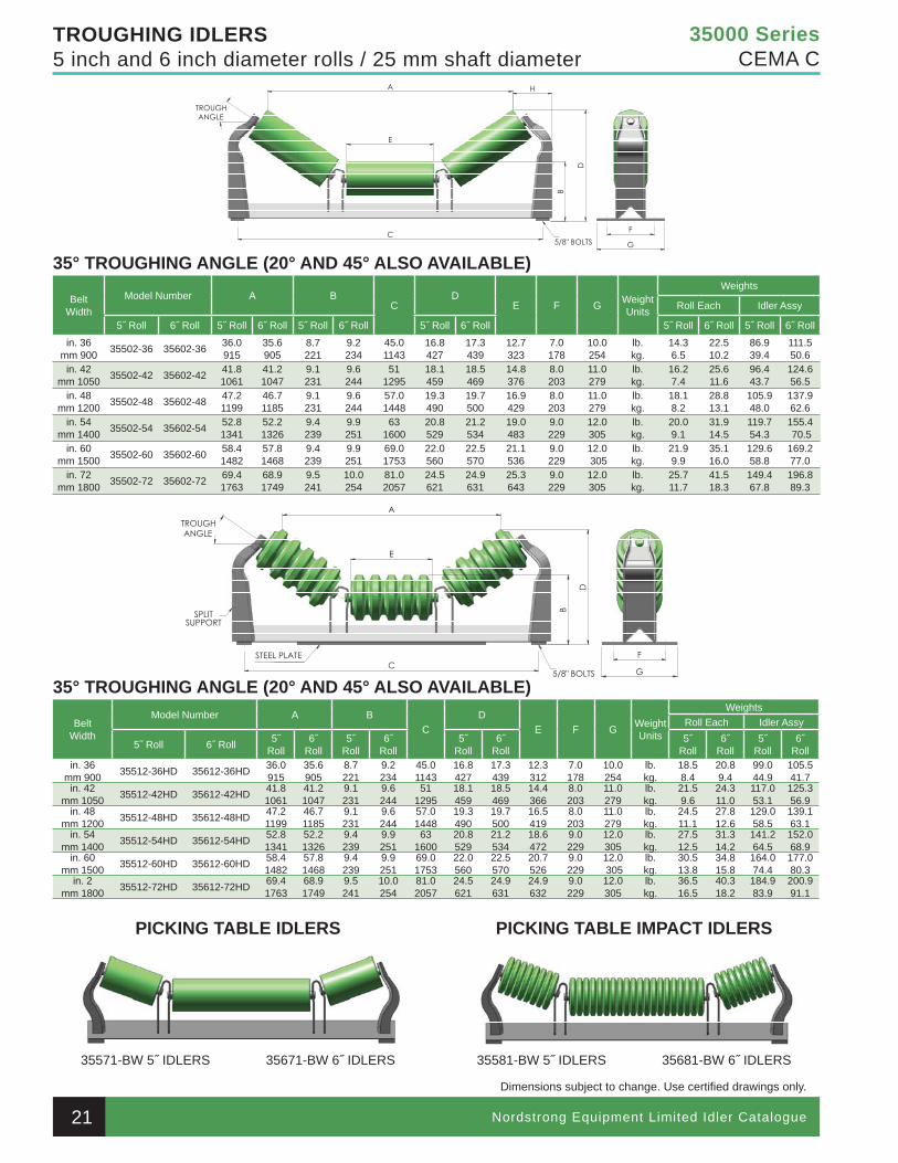
35000 SeriesCEMA C
TROUGHING IDLERS5 inch and 6 inch diameter rolls / 25 mm shaft diameter
35° TROUGHING ANGLE (20° AND 45° ALSO AVAILABLE)
BeltWidth
Model Number A BC
DE F G Weight
Units
Weights
Roll Each Idler Assy
5˝ Roll 6˝ Roll 5˝ Roll 6˝ Roll 5˝ Roll 6˝ Roll 5˝ Roll 6˝ Roll 5˝ Roll 6˝ Roll 5˝ Roll 6˝ Roll
in. 36mm 900 35502-36 35602-36 36.0
91535.6905
8.7221
9.2234
45.01143
16.8427
17.3439
12.7323
7.0178
10.0254
lb.kg.
14.36.5
22.510.2
86.939.4
111.550.6
in. 42mm 1050 35502-42 35602-42 41.8
106141.21047
9.1231
9.6244
511295
18.1459
18.5469
14.8376
8.0203
11.0279
lb.kg.
16.27.4
25.611.6
96.443.7
124.656.5
in. 48mm 1200 35502-48 35602-48 47.2
119946.71185
9.1231
9.6244
57.01448
19.3490
19.7500
16.9429
8.0203
11.0279
lb.kg.
18.18.2
28.813.1
105.948.0
137.962.6
in. 54mm 1400 35502-54 35602-54 52.8
134152.21326
9.4239
9.9251
631600
20.8529
21.2534
19.0483
9.0229
12.0305
lb.kg.
20.09.1
31.914.5
119.754.3
155.4 70.5
in. 60mm 1500 35502-60 35602-60 58.4
148257.81468
9.4239
9.9251
69.01753
22.0560
22.5570
21.1536
9.0229
12.0 305
lb.kg.
21.99.9
35.116.0
129.658.8
169.277.0
in. 72mm 1800 35502-72 35602-72 69.4
176368.91749
9.5241
10.0254
81.02057
24.5621
24.9631
25.3643
9.0229
12.0305
lb.kg.
25.711.7
41.518.3
149.467.8
196.889.3
35° TROUGHING ANGLE (20° AND 45° ALSO AVAILABLE)
BeltWidth
Model Number A BC
DE F G Weight
Units
WeightsRoll Each Idler Assy
5˝ Roll 6˝ Roll 5˝Roll
6˝Roll
5˝Roll
6˝Roll
5˝Roll
6˝Roll
5˝Roll
6˝Roll
5˝Roll
6˝Roll
in. 36mm 900 35512-36HD 35612-36HD 36.0
91535.6905
8.7221
9.2234
45.01143
16.8427
17.3439
12.3312
7.0178
10.0254
lb.kg.
18.58.4
20.89.4
99.044.9
105.541.7
in. 42mm 1050 35512-42HD 35612-42HD 41.8
106141.21047
9.1231
9.6244
511295
18.1459
18.5469
14.4366
8.0203
11.0279
lb.kg.
21.59.6
24.311.0
117.053.1
125.356.9
in. 48mm 1200 35512-48HD 35612-48HD 47.2
119946.71185
9.1231
9.6244
57.01448
19.3490
19.7500
16.5419
8.0203
11.0279
lb.kg.
24.511.1
27.812.6
129.058.5
139.163.1
in. 54mm 1400 35512-54HD 35612-54HD 52.8
134152.21326
9.4239
9.9251
631600
20.8529
21.2534
18.6472
9.0229
12.0305
lb.kg.
27.512.5
31.314.2
141.264.5
152.068.9
in. 60mm 1500 35512-60HD 35612-60HD 58.4
148257.81468
9.4239
9.9251
69.01753
22.0560
22.5570
20.7526
9.0229
12.0 305
lb.kg.
30.513.8
34.815.8
164.074.4
177.080.3
in. 2mm 1800 35512-72HD 35612-72HD 69.4
176368.91749
9.5241
10.0254
81.02057
24.5621
24.9631
24.9632
9.0229
12.0305
lb.kg.
36.516.5
40.318.2
184.983.9
200.991.1
PICKING TABLE IDLERS PICKING TABLE IMPACT IDLERS
35571-BW 5˝ IDLERS 35671-BW 6˝ IDLERS 35581-BW 5˝ IDLERS 35681-BW 6˝ IDLERS
30 000 & 35 000 Series Section.indd 20 9/24/2010 1:55:00 PM
Nordstrong Equipment Limited Idler Catalogue
Dimensions subject to change. Use certifi ed drawings only.
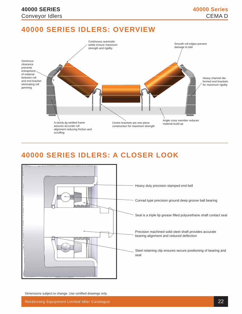
40000 SeriesCEMA D
40000 SERIESConveyor Idlers
Continuous automatic welds ensure maximum strength and rigidity
A sturdy jig welded frame assures accurate roll alignment reducing friction and scruffi ng
Centre brackets are one-piece construction for maximum strength
Angle cross member reducesmaterial build-up
Smooth roll edges prevent damage to belt
Generous clearance prevents entrapment of material betewen roll and end bracket eliminating roll jamming
Heavy duty precision stamped end bell
Conrad type precision ground deep groove ball bearing
Seal is a triple lip grease fi lled polyurethane shaft contact seal
Precision machined solid steel shaft provides accurate bearing alignment and reduced defl ection
Steel retaining clip ensures secure positioning of bearing and seal
40000 SERIES IDLERS: A CLOSER LOOK
40000 SERIES IDLERS: OVERVIEW
Heavy channel die-formed end brackets for maximum rigidity
22
40 000 Series Section.indd 21 9/24/2010 2:16:30 PM
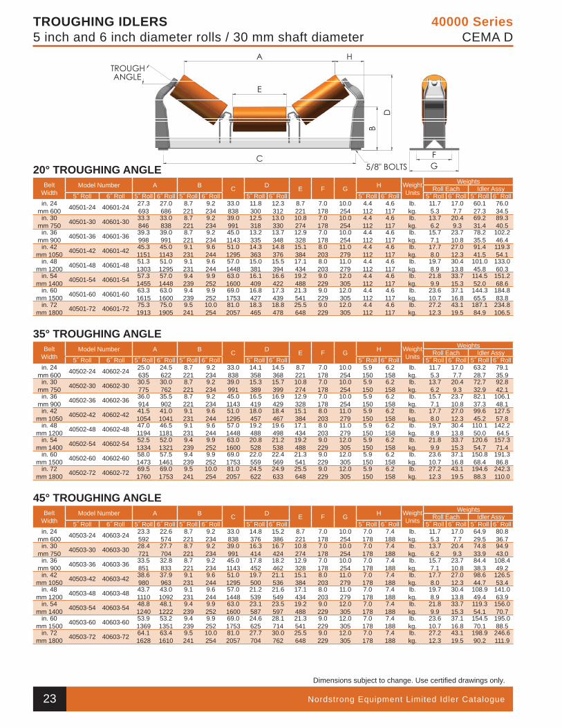
Nordstrong Equipment Limited Idler Catalogue
Dimensions subject to change. Use certifi ed drawings only.
40000 SeriesCEMA D
TROUGHING IDLERS5 inch and 6 inch diameter rolls / 30 mm shaft diameter
20° TROUGHING ANGLEBelt
WidthModel Number A B C D E F G H Weight
Units
WeightsRoll Each Idler Assy
5˝ Roll 6˝ Roll 5˝ Roll 6˝ Roll 5˝ Roll 6˝ Roll 5˝ Roll 6˝ Roll 5˝ Roll 6˝ Roll 5˝ Roll 6˝ Roll 5˝ Roll 6˝ Rollin. 24
mm 600 40501-24 40601-24 27.3693
27.0686
8.7221
9.2234
33.0838
11.8300
12.3312
8.7221
7.0178
10.0254
4.4112
4.6117
lb.kg.
11.75.3
17.07.7
60.127.3
76.034.5
in. 30mm 750 40501-30 40601-30 33.3
84633.0838
8.7221
9.2234
39.0991
12.5318
13.0330
10.8274
7.0178
10.0254
4.4112
4.6117
lb.kg.
13.76.2
20.49.3
69.231.4
89.340.5
in. 36mm 900 40501-36 40601-36 39.3
99839.0991
8.7221
9.2234
45.01143
13.2335
13.7348
12.9328
7.0178
10.0254
4.4112
4.6117
lb.kg.
15.77.1
23.710.8
78.235.5
102.246.4
in. 42mm 1050 40501-42 40601-42 45.3
115145.01143
9.1231
9.6244
51.01295
14.3363
14.8376
15.1384
8.0203
11.0279
4.4112
4.6117
lb.kg.
17.78.0
27.012.3
91.441.5
119.354.1
in. 48mm 1200 40501-48 40601-48 51.3
130351.01295
9.1231
9.6244
57.01448
15.0381
15.5394
17.1434
8.0203
11.0279
4.4112
4.6117
lb.kg.
19.78.9
30.413.8
101.045.8
133.060.3
in. 54mm 1400 40501-54 40601-54 57.3
145557.01448
9.4239
9.9252
63.01600
16.1409
16.6422
19.2488
9.0229
12.0305
4.4112
4.6117
lb.kg.
21.89.9
33.715.3
114.552.0
151.268.6
in. 60mm 1500 40501-60 40601-60 63.3
161563.01600
9.4239
9.9252
69.01753
16.8427
17.3439
21.3541
9.0229
12.0305
4.4112
4.6117
lb.kg.
23.610.7
37.116.8
144.365.5
184.883.8
in. 72mm 1800 40501-72 40601-72 75.3
191375.01905
9.5241
10.0254
81.02057
18.3465
18.8478
25.5648
9.0229
12.0305
4.4112
4.6117
lb.kg.
27.212.3
43.119.5
187.184.9
234.8106.5
35° TROUGHING ANGLEBelt
WidthModel Number A B C D E F G H Weight
Units
WeightsRoll Each Idler Assy
5˝ Roll 6˝ Roll 5˝ Roll 6˝ Roll 5˝ Roll 6˝ Roll 5˝ Roll 6˝ Roll 5˝ Roll 6˝ Roll 5˝ Roll 6˝ Roll 5˝ Roll 6˝ Rollin. 24
mm 600 40502-24 40602-24 25.0635
24.5622
8.7221
9.2234
33.0838
14.1358
14.5368
8.7221
7.0178
10.0254
5.9150
6.2158
lb.kg.
11.75.3
17.07.7
63.228.7
79.135.9
in. 30mm 750 40502-30 40602-30 30.5
77530.0762
8.7221
9.2234
39.0991
15.3389
15.7399
10.8274
7.0178
10.0254
5.9150
6.2158
lb.kg.
13.76.2
20.49.3
72.732.9
92.842.1
in. 36mm 900 40502-36 40602-36 36.0
91435.5902
8.7221
9.2234
45.01143
16.5419
16.9429
12.9328
7.0178
10.0254
5.9150
6.2158
lb.kg.
15.77.1
23.710.8
82.137.3
106.148.1
in. 42mm 1050 40502-42 40602-42 41.5
105441.01041
9.1231
9.6244
51.01295
18.0457
18.4467
15.1384
8.0203
11.0279
5.9150
6.2158
lb.kg.
17.78.0
27.012.3
99.645.2
127.557.8
in. 48mm 1200 40502-48 40602-48 47.0
119446.51181
9.1231
9.6244
57.01448
19.2488
19.6498
17.1434
8.0203
11.0279
5.9150
6.2158
lb.kg.
19.78.9
30.413.8
110.150.0
142.2 64.5
in. 54mm 1400 40502-54 40602-54 52.5
133452.01321
9.4239
9.9252
63.01600
20.8528
21.2538
19.2488
9.0229
12.0305
5.9150
6.2158
lb.kg.
21.89.9
33.715.3
120.654.7
157.371.4
in. 60mm 1500 40502-60 40602-60 58.0
147357.51461
9.4239
9.9252
69.01753
22.0559
22.4569
21.3541
9.0229
12.0305
5.9150
6.2158
lb.kg.
23.610.7
37.116.8
150.868.4
191.386.8
in. 72mm 1800 40502-72 40602-72 69.5
176069.01753
9.5241
10.0254
81.02057
24.5622
24.9633
25.5648
9.0229
12.0305
5.9150
6.2158
lb.kg.
27.212.3
43.119.5
194.688.3
242.3110.0
45° TROUGHING ANGLEBelt
WidthModel Number A B C D E F G H Weight
Units
WeightsRoll Each Idler Assy
5˝ Roll 6˝ Roll 5˝ Roll 6˝ Roll 5˝ Roll 6˝ Roll 5˝ Roll 6˝ Roll 5˝ Roll 6˝ Roll 5˝ Roll 6˝ Roll 5˝ Roll 6˝ Rollin. 24
mm 600 40503-24 40603-24 23.3592
22.6574
8.7221
9.2234
33.0838
14.8376
15.2386
8.7221
7.0178
10.0254
7.0178
7.4188
lb.kg.
11.75.3
17.07.7
64.929.5
80.836.7
in. 30mm 750 40503-30 40603-30 28.4
72127.7704
8.7221
9.2234
39.0991
16.3414
16.7424
10.8274
7.0178
10.0254
7.0178
7.4188
lb.kg.
13.76.2
20.49.3
74.833.9
94.943.0
in. 36mm 900 40503-36 40603-36 33.5
85132.8833
8.7221
9.2234
45.01143
17.8452
18.2462
12.9328
7.0178
10.0254
7.0178
7.4188
lb.kg.
15.77.1
23.710.8
84.438.3
108.449.2
in. 42mm 1050 40503-42 40603-42 38.6
98037.9963
9.1231
9.6244
51.01295
19.7500
21.1536
15.1384
8.0203
11.0279
7.0178
7.4188
lb.kg.
17.78.0
27.012.3
98.644.7
126.553.4
in. 48mm 1200 40503-48 40603-48 43.7
111043.01092
9.1231
9.6244
57.01448
21.2539
21.6549
17.1434
8.0203
11.0279
7.0178
7.4188
lb.kg.
19.78.9
30.413.8
108.949.4
141.063.9
in. 54mm 1400 40503-54 40603-54 48.8
124048.11222
9.4239
9.9252
63.01600
23.1587
23.5597
19.2488
9.0229
12.0305
7.0178
7.4188
lb.kg.
21.89.9
33.715.3
119.354.1
156.070.7
in. 60mm 1500 40503-60 40603-60 53.9
136953.21351
9.4239
9.9252
69.01753
24.6625
28.1714
21.3541
9.0229
12.0305
7.0178
7.4188
lb.kg.
23.610.7
37.116.8
154.570.1
195.088.5
in. 72mm 1800 40503-72 40603-72 64.1
162863.41610
9.5241
10.0254
81.02057
27.7704
30.0762
25.5648
9.0229
12.0305
7.0178
7.4188
lb.kg.
27.212.3
43.119.5
198.990.2
246.6111.9
23
40 000 Series Section.indd 22 9/24/2010 2:16:38 PM
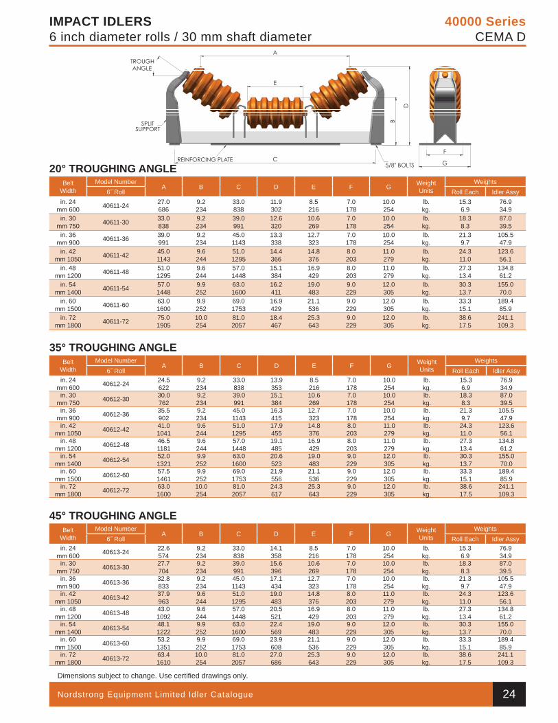
Nordstrong Equipment Limited Idler Catalogue
Dimensions subject to change. Use certifi ed drawings only.
40000 SeriesCEMA D
IMPACT IDLERS6 inch diameter rolls / 30 mm shaft diameter
20° TROUGHING ANGLEBelt
WidthModel Number
A B C D E F G Weight Units
Weights6˝ Roll Roll Each Idler Assy
in. 24mm 600 40611-24 27.0
6869.2234
33.0838
11.9302
8.5216
7.0178
10.0254
lb.kg.
15.36.9
76.934.9
in. 30mm 750 40611-30 33.0
8389.2234
39.0991
12.6320
10.6269
7.0178
10.0254
lb.kg.
18.38.3
87.039.5
in. 36mm 900 40611-36 39.0
9919.2234
45.01143
13.3338
12.7323
7.0178
10.0254
lb.kg.
21.39.7
105.547.9
in. 42mm 1050 40611-42 45.0
11439.6244
51.01295
14.4366
14.8376
8.0203
11.0279
lb.kg.
24.311.0
123.656.1
in. 48mm 1200 40611-48 51.0
12959.6244
57.01448
15.1384
16.9429
8.0203
11.0279
lb.kg.
27.313.4
134.861.2
in. 54mm 1400 40611-54 57.0
14489.9252
63.01600
16.2411
19.0483
9.0229
12.0305
lb.kg.
30.313.7
155.070.0
in. 60mm 1500 40611-60 63.0
16009.9252
69.01753
16.9429
21.1536
9.0229
12.0305
lb.kg.
33.315.1
189.485.9
in. 72mm 1800 40611-72 75.0
190510.0254
81.02057
18.4467
25.3643
9.0229
12.0305
lb.kg.
38.617.5
241.1109.3
35° TROUGHING ANGLEBelt
WidthModel Number
A B C D E F G Weight Units
Weights6˝ Roll Roll Each Idler Assy
in. 24mm 600 40612-24 24.5
6229.2234
33.0838
13.9353
8.5216
7.0178
10.0254
lb.kg.
15.36.9
76.934.9
in. 30mm 750 40612-30 30.0
7629.2234
39.0991
15.1384
10.6269
7.0178
10.0254
lb.kg.
18.38.3
87.039.5
in. 36mm 900 40612-36 35.5
9029.2234
45.01143
16.3415
12.7323
7.0178
10.0254
lb.kg.
21.39.7
105.547.9
in. 42mm 1050 40612-42 41.0
10419.6244
51.01295
17.9455
14.8376
8.0203
11.0279
lb.kg.
24.311.0
123.656.1
in. 48mm 1200 40612-48 46.5
11819.6244
57.01448
19.1485
16.9429
8.0203
11.0279
lb.kg.
27.313.4
134.861.2
in. 54mm 1400 40612-54 52.0
13219.9252
63.01600
20.6523
19.0483
9.0229
12.0305
lb.kg.
30.313.7
155.070.0
in. 60mm 1500 40612-60 57.5
14619.9252
69.01753
21.9556
21.1536
9.0229
12.0305
lb.kg.
33.315.1
189.485.9
in. 72mm 1800 40612-72 63.0
160010.0254
81.02057
24.3617
25.3643
9.0229
12.0305
lb.kg.
38.617.5
241.1109.3
45° TROUGHING ANGLEBelt
WidthModel Number
A B C D E F G Weight Units
Weights6˝ Roll Roll Each Idler Assy
in. 24mm 600 40613-24 22.6
5749.2234
33.0838
14.1358
8.5216
7.0178
10.0254
lb.kg.
15.36.9
76.934.9
in. 30mm 750 40613-30 27.7
7049.2234
39.0991
15.6396
10.6269
7.0178
10.0254
lb.kg.
18.38.3
87.039.5
in. 36mm 900 40613-36 32.8
8339.2234
45.01143
17.1434
12.7323
7.0178
10.0254
lb.kg.
21.39.7
105.547.9
in. 42mm 1050 40613-42 37.9
9639.6244
51.01295
19.0483
14.8376
8.0203
11.0279
lb.kg.
24.311.0
123.656.1
in. 48mm 1200 40613-48 43.0
10929.6244
57.01448
20.5521
16.9429
8.0203
11.0279
lb.kg.
27.313.4
134.861.2
in. 54mm 1400 40613-54 48.1
12229.9252
63.01600
22.4569
19.0483
9.0229
12.0305
lb.kg.
30.313.7
155.070.0
in. 60mm 1500 40613-60 53.2
13519.9252
69.01753
23.9608
21.1536
9.0229
12.0305
lb.kg.
33.315.1
189.485.9
in. 72mm 1800 40613-72 63.4
161010.0254
81.02057
27.0686
25.3643
9.0229
12.0305
lb.kg.
38.617.5
241.1109.3
24
40 000 Series Section.indd 23 9/24/2010 2:16:40 PM
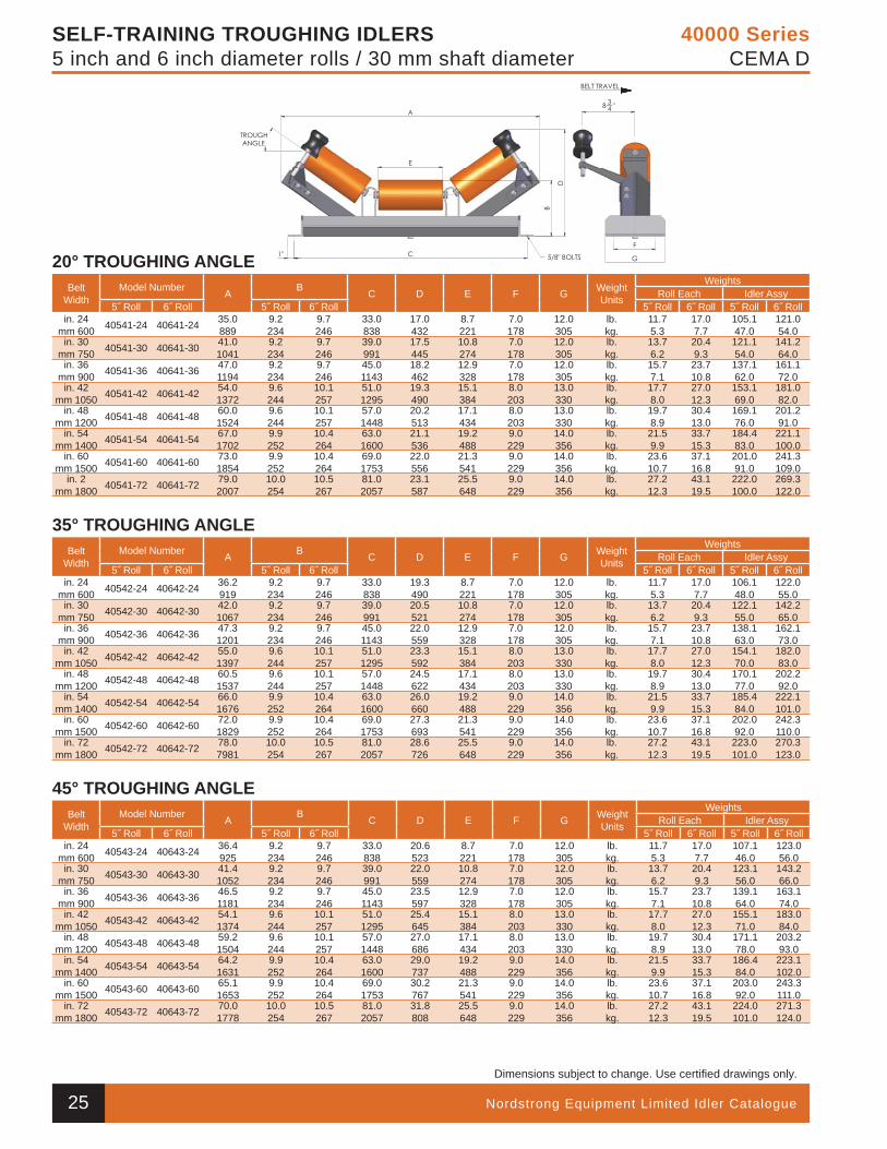
Nordstrong Equipment Limited Idler Catalogue
Dimensions subject to change. Use certifi ed drawings only.
40000 SeriesCEMA D
SELF-TRAINING TROUGHING IDLERS5 inch and 6 inch diameter rolls / 30 mm shaft diameter
20° TROUGHING ANGLEBelt
WidthModel Number A B C D E F G Weight
Units
WeightsRoll Each Idler Assy
5˝ Roll 6˝ Roll 5˝ Roll 6˝ Roll 5˝ Roll 6˝ Roll 5˝ Roll 6˝ Rollin. 24
mm 600 40541-24 40641-24 35.0889
9.2234
9.7246
33.0838
17.0432
8.7221
7.0178
12.0305
lb.kg.
11.75.3
17.07.7
105.147.0
121.054.0
in. 30mm 750 40541-30 40641-30 41.0
10419.2234
9.7246
39.0991
17.5445
10.8274
7.0178
12.0305
lb.kg.
13.76.2
20.49.3
121.154.0
141.264.0
in. 36mm 900 40541-36 40641-36 47.0
11949.2234
9.7246
45.01143
18.2462
12.9328
7.0178
12.0305
lb.kg.
15.77.1
23.710.8
137.162.0
161.172.0
in. 42mm 1050 40541-42 40641-42 54.0
13729.6244
10.1257
51.01295
19.3490
15.1384
8.0203
13.0330
lb.kg.
17.78.0
27.012.3
153.169.0
181.082.0
in. 48mm 1200 40541-48 40641-48 60.0
15249.6244
10.1257
57.01448
20.2513
17.1434
8.0203
13.0330
lb.kg.
19.78.9
30.413.0
169.176.0
201.291.0
in. 54mm 1400 40541-54 40641-54 67.0
17029.9252
10.4264
63.01600
21.1536
19.2488
9.0229
14.0356
lb.kg.
21.59.9
33.715.3
184.483.0
221.1100.0
in. 60mm 1500 40541-60 40641-60 73.0
18549.9252
10.4264
69.01753
22.0556
21.3541
9.0229
14.0356
lb.kg.
23.610.7
37.116.8
201.091.0
241.3109.0
in. 2mm 1800 40541-72 40641-72 79.0
200710.0254
10.5267
81.02057
23.1587
25.5648
9.0229
14.0356
lb.kg.
27.212.3
43.119.5
222.0100.0
269.3122.0
35° TROUGHING ANGLEBelt
WidthModel Number A B C D E F G Weight
Units
WeightsRoll Each Idler Assy
5˝ Roll 6˝ Roll 5˝ Roll 6˝ Roll 5˝ Roll 6˝ Roll 5˝ Roll 6˝ Rollin. 24
mm 600 40542-24 40642-24 36.2 919
9.2234
9.7246
33.0838
19.3490
8.7221
7.0178
12.0305
lb.kg.
11.75.3
17.07.7
106.148.0
122.055.0
in. 30mm 750 40542-30 40642-30 42.0
10679.2234
9.7246
39.0991
20.5521
10.8274
7.0178
12.0305
lb.kg.
13.76.2
20.49.3
122.155.0
142.265.0
in. 36mm 900 40542-36 40642-36 47.3
12019.2234
9.7246
45.01143
22.0559
12.9328
7.0178
12.0305
lb.kg.
15.77.1
23.710.8
138.163.0
162.173.0
in. 42mm 1050 40542-42 40642-42 55.0
13979.6244
10.1257
51.01295
23.3592
15.1384
8.0203
13.0330
lb.kg.
17.78.0
27.012.3
154.170.0
182.083.0
in. 48mm 1200 40542-48 40642-48 60.5
15379.6244
10.1257
57.01448
24.5622
17.1434
8.0203
13.0330
lb.kg.
19.78.9
30.413.0
170.177.0
202.292.0
in. 54mm 1400 40542-54 40642-54 66.0
16769.9252
10.4264
63.01600
26.0660
19.2488
9.0229
14.0356
lb.kg.
21.59.9
33.715.3
185.484.0
222.1101.0
in. 60mm 1500 40542-60 40642-60 72.0
18299.9252
10.4264
69.01753
27.3693
21.3541
9.0229
14.0356
lb.kg.
23.610.7
37.116.8
202.092.0
242.3110.0
in. 72mm 1800 40542-72 40642-72 78.0
798110.0254
10.5267
81.02057
28.6726
25.5648
9.0229
14.0356
lb.kg.
27.212.3
43.119.5
223.0101.0
270.3123.0
45° TROUGHING ANGLEBelt
WidthModel Number A B C D E F G Weight
Units
WeightsRoll Each Idler Assy
5˝ Roll 6˝ Roll 5˝ Roll 6˝ Roll 5˝ Roll 6˝ Roll 5˝ Roll 6˝ Rollin. 24
mm 600 40543-24 40643-24 36.4925
9.2234
9.7246
33.0838
20.6523
8.7221
7.0178
12.0305
lb.kg.
11.75.3
17.07.7
107.146.0
123.056.0
in. 30mm 750 40543-30 40643-30 41.4
10529.2234
9.7246
39.0991
22.0559
10.8274
7.0178
12.0305
lb.kg.
13.76.2
20.49.3
123.156.0
143.266.0
in. 36mm 900 40543-36 40643-36 46.5
11819.2234
9.7246
45.01143
23.5597
12.9328
7.0178
12.0305
lb.kg.
15.77.1
23.710.8
139.164.0
163.174.0
in. 42mm 1050 40543-42 40643-42 54.1
13749.6244
10.1257
51.01295
25.4645
15.1384
8.0203
13.0330
lb.kg.
17.78.0
27.012.3
155.171.0
183.084.0
in. 48mm 1200 40543-48 40643-48 59.2
15049.6244
10.1257
57.01448
27.0686
17.1434
8.0203
13.0330
lb.kg.
19.78.9
30.413.0
171.178.0
203.293.0
in. 54mm 1400 40543-54 40643-54 64.2
16319.9252
10.4264
63.01600
29.0737
19.2488
9.0229
14.0356
lb.kg.
21.59.9
33.715.3
186.484.0
223.1102.0
in. 60mm 1500 40543-60 40643-60 65.1
16539.9252
10.4264
69.01753
30.2767
21.3541
9.0229
14.0356
lb.kg.
23.610.7
37.116.8
203.092.0
243.3111.0
in. 72mm 1800 40543-72 40643-72 70.0
177810.0254
10.5267
81.02057
31.8808
25.5648
9.0229
14.0356
lb.kg.
27.212.3
43.119.5
224.0101.0
271.3124.0
25
40 000 Series Section.indd 24 9/24/2010 2:16:42 PM
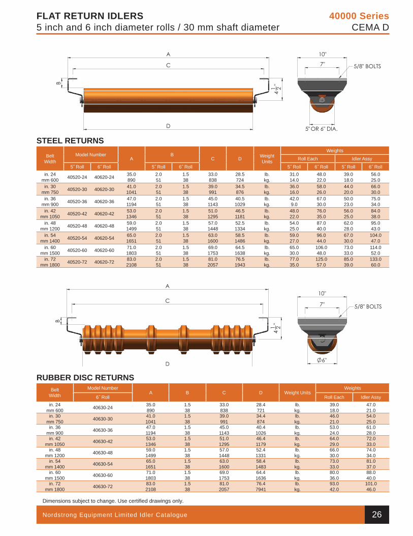
Nordstrong Equipment Limited Idler Catalogue
Dimensions subject to change. Use certifi ed drawings only.
40000 SeriesCEMA D
FLAT RETURN IDLERS5 inch and 6 inch diameter rolls / 30 mm shaft diameter
STEEL RETURNS
BeltWidth
Model NumberA
BC D Weight
Units
Weights
Roll Each Idler Assy
5˝ Roll 6˝ Roll 5˝ Roll 6˝ Roll 5˝ Roll 6˝ Roll 5˝ Roll 6˝ Rollin. 24
mm 600 40520-24 40620-24 35.0890
2.051
1.538
33.0838
28.5724
lb.kg.
31.014.0
48.022.0
39.018.0
56.025.0
in. 30mm 750 40520-30 40620-30 41.0
10412.051
1.538
39.0991
34.5876
lb.kg.
36.016.0
58.026.0
44.020.0
66.030.0
in. 36mm 900 40520-36 40620-36 47.0
11942.051
1.538
45.01143
40.51029
lb.kg.
42.09.0
67.030.0
50.023.0
75.034.0
in. 42mm 1050 40520-42 40620-42 53.0
13462.051
1.538
51.0 1295
46.51181
lb.kg.
48.022.0
76.035.0
56.025.0
84.038.0
in. 48mm 1200 40520-48 40620-48 59.0
14992.051
1.538
57.01448
52.51334
lb.kg.
54.025.0
87.040.0
62.028.0
95.043.0
in. 54mm 1400 40520-54 40620-54 65.0
16512.051
1.538
63.01600
58.51486
lb.kg.
59.027.0
96.044.0
67.030.0
104.047.0
in. 60mm 1500 40520-60 40620-60 71.0
18032.051
1.538
69.01753
64.51638
lb.kg.
65.030.0
106.048.0
73.033.0
114.052.0
in. 72mm 1800 40520-72 40620-72 83.0
21082.051
1.538
81.02057
76.51943
lb.kg.
77.035.0
125.057.0
85.039.0
133.060.0
RUBBER DISC RETURNSBelt
WidthModel Number
A B C D Weight UnitsWeights
6˝ Roll Roll Each Idler Assyin. 24
mm 600 40630-24 35.0890
1.538
33.0838
28.4721
lb.kg.
39.018.0
47.021.0
in. 30mm 750 40630-30 41.0
10411.538
39.0991
34.4874
lb.kg.
46.021.0
54.025.0
in. 36mm 900 40630-36 47.0
11941.538
45.01143
40.41026
lb.kg.
53.024.0
61.028.0
in. 42mm 1050 40630-42 53.0
13461.538
51.01295
46.41179
lb.kg.
64.029.0
72.033.0
in. 48mm 1200 40630-48 59.0
14991.538
57.01448
52.41331
lb.kg.
66.030.0
74.034.0
in. 54mm 1400 40630-54 65.0
16511.538
63.01600
58.41483
lb.kg.
73.033.0
81.037.0
in. 60mm 1500 40630-60 71.0
18031.538
69.01753
64.41636
lb.kg.
80.036.0
88.040.0
in. 72mm 1800 40630-72 83.0
21081.538
81.02057
76.47941
lb.kg.
93.042.0
101.046.0
26
40 000 Series Section.indd 25 9/24/2010 2:16:44 PM
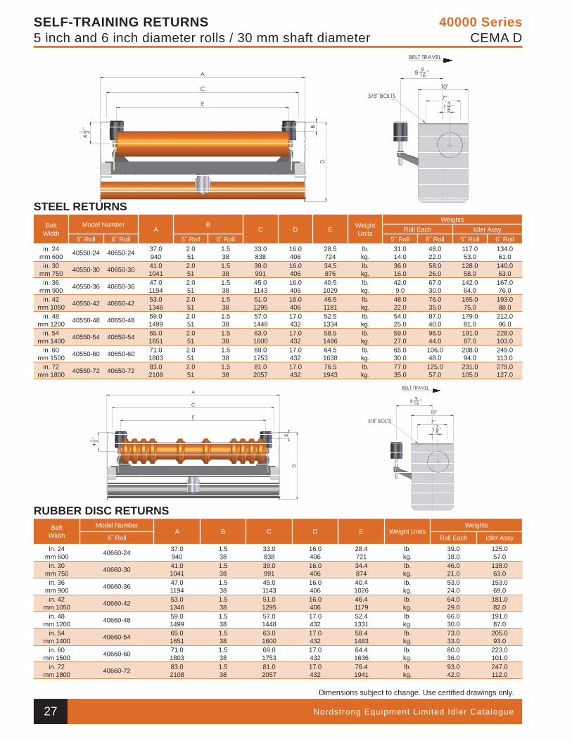
Nordstrong Equipment Limited Idler Catalogue
Dimensions subject to change. Use certifi ed drawings only.
40000 SeriesCEMA D
SELF-TRAINING RETURNS5 inch and 6 inch diameter rolls / 30 mm shaft diameter
STEEL RETURNSBelt
WidthModel Number
AB
C D E Weight Units
WeightsRoll Each Idler Assy
5˝ Roll 6˝ Roll 5˝ Roll 6˝ Roll 5˝ Roll 6˝ Roll 5˝ Roll 6˝ Rollin. 24
mm 600 40550-24 40650-24 37.0940
2.051
1.538
33.0838
16.0406
28.5724
lb.kg.
31.014.0
48.022.0
117.053.0
134.061.0
in. 30mm 750 40550-30 40650-30 41.0
10412.051
1.538
39.0991
16.0406
34.5876
lb.kg.
36.016.0
58.026.0
128.058.0
140.063.0
in. 36mm 900 40550-36 40650-36 47.0
11942.051
1.538
45.01143
16.0406
40.51029
lb.kg.
42.09.0
67.030.0
142.064.0
167.076.0
in. 42mm 1050 40550-42 40650-42 53.0
13462.051
1.538
51.0 1295
16.0406
46.51181
lb.kg.
48.022.0
76.035.0
165.075.0
193.088.0
in. 48mm 1200 40550-48 40650-48 59.0
14992.051
1.538
57.01448
17.0432
52.51334
lb.kg.
54.025.0
87.040.0
179.081.0
212.096.0
in. 54mm 1400 40550-54 40650-54 65.0
16512.051
1.538
63.01600
17.0432
58.51486
lb.kg.
59.027.0
96.044.0
191.087.0
228.0103.0
in. 60mm 1500 40550-60 40650-60 71.0
18032.051
1.538
69.01753
17.0432
64.51638
lb.kg.
65.030.0
106.048.0
208.094.0
249.0113.0
in. 72mm 1800 40550-72 40650-72 83.0
21082.051
1.538
81.02057
17.0432
76.51943
lb.kg.
77.035.0
125.057.0
231.0105.0
279.0127.0
RUBBER DISC RETURNSBelt
WidthModel Number
A B C D E Weight UnitsWeights
6˝ Roll Roll Each Idler Assy
in. 24mm 600 40660-24 37.0
9401.538
33.0838
16.0406
28.4721
lb.kg.
39.018.0
125.057.0
in. 30mm 750 40660-30 41.0
10411.538
39.0991
16.0406
34.4874
lb.kg.
46.021.0
138.063.0
in. 36mm 900 40660-36 47.0
11941.538
45.01143
16.0406
40.41026
lb.kg.
53.024.0
153.069.0
in. 42mm 1050 40660-42 53.0
13461.538
51.01295
16.0406
46.41179
lb.kg.
64.029.0
181.082.0
in. 48mm 1200 40660-48 59.0
14991.538
57.01448
17.0432
52.41331
lb.kg.
66.030.0
191.087.0
in. 54mm 1400 40660-54 65.0
16511.538
63.01600
17.0432
58.41483
lb.kg.
73.033.0
205.093.0
in. 60mm 1500 40660-60 71.0
18031.538
69.01753
17.0432
64.41636
lb.kg.
80.036.0
223.0101.0
in. 72mm 1800 40660-72 83.0
21081.538
81.02057
17.0432
76.41941
lb.kg.
93.042.0
247.0112.0
27
40 000 Series Section.indd 26 9/24/2010 2:16:47 PM
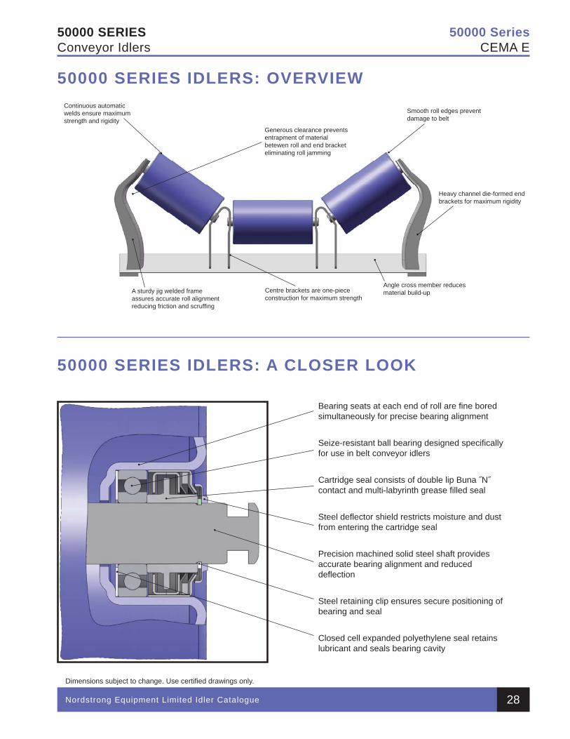
Nordstrong Equipment Limited Idler Catalogue
Dimensions subject to change. Use certifi ed drawings only.
50000 SeriesCEMA E
50000 SERIESConveyor Idlers
Continuous automatic welds ensure maximum strength and rigidity
A sturdy jig welded frame assures accurate roll alignment reducing friction and scruffi ng
Centre brackets are one-piece construction for maximum strength
Angle cross member reducesmaterial build-up
Smooth roll edges prevent damage to belt
Heavy channel die-formed end brackets for maximum rigidity
Generous clearance prevents entrapment of material betewen roll and end bracket eliminating roll jamming
Bearing seats at each end of roll are fi ne bored simultaneously for precise bearing alignment
Seize-resistant ball bearing designed specifi cally for use in belt conveyor idlers
Cartridge seal consists of double lip Buna ˝N˝ contact and multi-labyrinth grease fi lled seal
Steel defl ector shield restricts moisture and dust from entering the cartridge seal
Precision machined solid steel shaft provides accurate bearing alignment and reduced defl ection
Steel retaining clip ensures secure positioning of bearing and seal
Closed cell expanded polyethylene seal retains lubricant and seals bearing cavity
50000 SERIES IDLERS: A CLOSER LOOK
50000 SERIES IDLERS: OVERVIEW
28
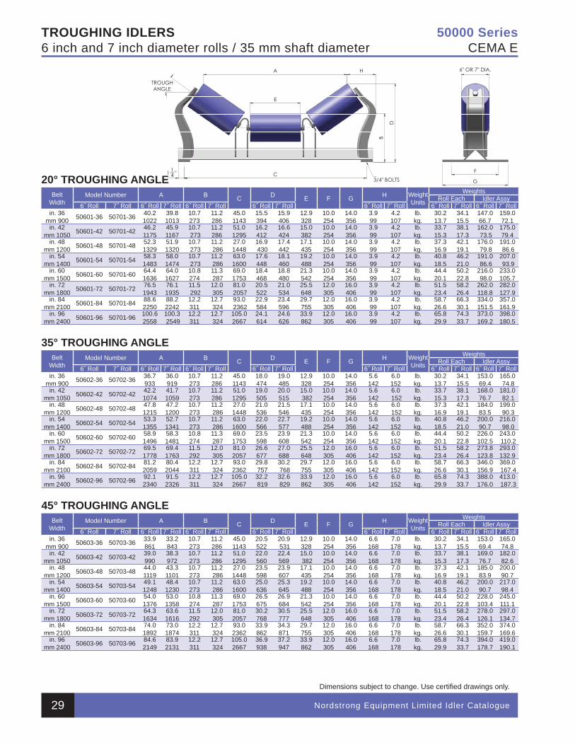
TROUGHING IDLERS6 inch and 7 inch diameter rolls / 35 mm shaft diameter
Nordstrong Equipment Limited Idler Catalogue
Dimensions subject to change. Use certifi ed drawings only.
50000 SeriesCEMA E
20° TROUGHING ANGLEBelt
WidthModel Number A B C D E F G H Weight
Units
WeightsRoll Each Idler Assy
6˝ Roll 7˝ Roll 6˝ Roll 7˝ Roll 6˝ Roll 7˝ Roll 6˝ Roll 7˝ Roll 6˝ Roll 7˝ Roll 6˝ Roll 7˝ Roll 6˝ Roll 7˝ Rollin. 36
mm 900 50601-36 50701-36 40.21022
39.81013
10.7273
11.2286
45.01143
15.5 394
15.9 406
12.9 328
10.0 254
14.0 356
3.9 99
4.2 107
lb.kg.
30.2 13.7
34.1 15.5
147.0 66.7
159.0 72.1
in. 42 mm 1050 50601-42 50701-42 46.2
117545.91167
10.7 273
11.2286
51.01295
16.2 412
16.6 424
15.0 382
10.0 254
14.0 356
3.9 99
4.2 107
lb.kg.
33.7 15.3
38.1 17.3
162.0 73.5
175.0 79.4
in. 48 mm 1200 50601-48 50701-48 52.3
132951.91320
10.7 273
11.2 286
27.0 1448
16.9 430
17.4 442
17.1 435
10.0 254
14.0 356
3.9 99
4.2 107
lb.kg.
37.3 16.9
42.1 19.1
176.0 79.8
191.0 86.6
in. 54 mm 1400 50601-54 50701-54 58.3
148358.01474
10.7 273
11.2 286
63.0 1600
17.6 448
18.1 460
19.2 488
10.0 254
14.0 356
3.9 99
4.2 107
lb.kg.
40.8 18.5
46.2 21.0
191.0 86.6
207.0 93.9
in. 60 mm 1500 50601-60 50701-60 64.4
163664.01627
10.8274
11.3 287
69.0 1753
18.4 468
18.8 480
21.3 542
10.0 254
14.0 356
3.9 99
4.2 107
lb.kg.
44.4 20.1
50.2 22.8
216.0 98.0
233.0 105.7
in. 72 mm 1800 50601-72 50701-72 76.5
194376.11935
11.5 292
12.0 305
81.0 2057
20.5 522
21.0 534
25.5 648
12.0 305
16.0 406
3.9 99
4.2 107
lb.kg.
51.5 23.4
58.2 26.4
262.0 118.8
282.0 127.9
in. 84 mm 2100 50601-84 50701-84 88.6
225088.22242
12.2 311
12.7 324
93.0 2362
22.9 584
23.4 596
29.7 755
12.0 305
16.0 406
3.9 99
4.2 107
lb.kg.
58.7 26.6
66.3 30.1
334.0 151.5
357.0 161.9
in. 96 mm 2400 50601-96 50701-96 100.6
2558100.3 2549
12.2 311
12.7 324
105.0 2667
24.1 614
24.6 626
33.9 862
12.0 305
16.0 406
3.9 99
4.2 107
lb.kg.
65.8 29.9
74.3 33.7
373.0 169.2
398.0 180.5
35° TROUGHING ANGLEBelt
WidthModel Number A B C D E F G H Weight
Units
WeightsRoll Each Idler Assy
6˝ Roll 7˝ Roll 6˝ Roll 7˝ Roll 6˝ Roll 7˝ Roll 6˝ Roll 7˝ Roll 6˝ Roll 7˝ Roll 6˝ Roll 7˝ Roll 6˝ Roll 7˝ Rollin. 36
mm 900 50602-36 50702-36 36.7933
36.0 919
10.7273
11.2286
45.01143
18.0 474
19.0 485
12.9 328
10.0 254
14.0 356
5.6 142
6.0 152
lb.kg.
30.2 13.7
34.1 15.5
153.0 69.4
165.0 74.8
in. 42 mm 1050 50602-42 50702-42 42.2
107441.7 1059
10.7273
11.2286
51.01295
19.0 505
20.0 515
15.0 382
10.0 254
14.0 356
5.6 142
6.0 152
lb.kg.
33.7 15.3
38.1 17.3
168.0 76.7
181.0 82.1
in. 48 mm 1200 50602-48 50702-48 47.8
121547.2 1200
10.7273
11.2 286
27.0 1448
21.0 536
21.5 546
17.1 435
10.0 254
14.0 356
5.6 142
6.0 152
lb.kg.
37.3 16.9
42.1 19.1
184.0 83.5
199.0 90.3
in. 54 mm 1400 50602-54 50702-54 53.3
135552.7 1341
10.7273
11.2 286
63.0 1600
22.0 566
22.7 577
19.2 488
10.0 254
14.0 356
5.6 142
6.0 152
lb.kg.
40.8 18.5
46.2 21.0
200.0 90.7
216.0 98.0
in. 60 mm 1500 50602-60 50702-60 58.9
149658.3 1481
10.8274
11.3 287
69.0 1753
23.5 598
23.9 608
21.3 542
10.0 254
14.0 356
5.6 142
6.0 152
lb.kg.
44.4 20.1
50.2 22.8
226.0 102.5
243.0 110.2
in. 72 mm 1800 50602-72 50702-72 69.5
177869.4 1763
11.5292
12.0 305
81.0 2057
26.6 677
27.0 688
25.5 648
12.0 305
16.0 406
5.6 142
6.0 152
lb.kg.
51.5 23.4
58.2 26.4
273.8 123.8
293.0 132.9
in. 84 mm 2100 50602-84 50702-84 81.2
205980.4 2044
12.2 311
12.7 324
93.0 2362
29.8 757
30.2 768
29.7 755
12.0 305
16.0 406
5.6 142
6.0 152
lb.kg.
58.7 26.6
66.3 30.1
346.0 156.9
369.0 167.4
in. 96 mm 2400 50602-96 50702-96 92.1
234091.5 2326
12.2 311
12.7 324
105.0 2667
32.2 819
32.6 829
33.9 862
12.0 305
16.0 406
5.6 142
6.0 152
lb.kg.
65.8 29.9
74.3 33.7
388.0 176.0
413.0 187.3
45° TROUGHING ANGLEBelt
WidthModel Number A B C D E F G H Weight
Units
WeightsRoll Each Idler Assy
6˝ Roll 7˝ Roll 6˝ Roll 7˝ Roll 6˝ Roll 7˝ Roll 6˝ Roll 7˝ Roll 6˝ Roll 7˝ Roll 6˝ Roll 7˝ Roll 6˝ Roll 7˝ Rollin. 36
mm 900 50603-36 50703-36 33.9 861
33.2 843
10.7273
11.2286
45.01143
20.5 522
20.9 531
12.9 328
10.0 254
14.0 356
6.6 168
7.0 178
lb.kg.
30.2 13.7
34.1 15.5
153.0 69.4
165.0 74.8
in. 42 mm 1050 50603-42 50703-42 39.0
99038.3 972
10.7273
11.2286
51.01295
22.0 560
22.4 569
15.0 382
10.0 254
14.0 356
6.6 168
7.0 178
lb.kg.
33.7 15.3
38.1 17.3
169.0 76.7
182.0 82.6
in. 48 mm 1200 50603-48 50703-48 44.0
111943.3 1101
10.7273
11.2 286
27.0 1448
23.5 598
23.9 607
17.1 435
10.0 254
14.0 356
6.6 168
7.0 178
lb.kg.
37.3 16.9
42.1 19.1
185.0 83.9
200.0 90.7
in. 54 mm 1400 50603-54 50703-54 49.1
124848.4 1230
10.7273
11.2 286
63.0 1600
25.0 636
25.3 645
19.2 488
10.0 254
14.0 356
6.6 168
7.0 178
lb.kg.
40.8 18.5
46.2 21.0
200.0 90.7
217.0 98.4
in. 60 mm 1500 50603-60 50703-60 54.0
137653.0 1358
10.8274
11.3 287
69.0 1753
26.5 675
26.9 684
21.3 542
10.0 254
14.0 356
6.6 168
7.0 178
lb.kg.
44.4 20.1
50.2 22.8
228.0 103.4
245.0 111.1
in. 72 mm 1800 50603-72 50703-72 64.3
163463.6 1616
11.5292
12.0 305
81.0 2057
30.2 768
30.5 777
25.5 648
12.0 305
16.0 406
6.6 168
7.0 178
lb.kg.
51.5 23.4
58.2 26.4
278.0 126.1
297.0 134.7
in. 84 mm 2100 50603-84 50703-84 74.0
189273.0 1874
12.2 311
12.7 324
93.0 2362
33.9 862
34.3 871
29.7 755
12.0 305
16.0 406
6.6 168
7.0 178
lb.kg.
58.7 26.6
66.3 30.1
352.0 159.7
374.0 169.6
in. 96 mm 2400 50603-96 50703-96 84.6
214983.9 2131
12.2 311
12.7 324
105.0 2667
36.9 938
37.2 947
33.9 862
12.0 305
16.0 406
6.6 168
7.0 178
lb.kg.
65.8 29.9
74.3 33.7
394.0 178.7
419.0190.1
29
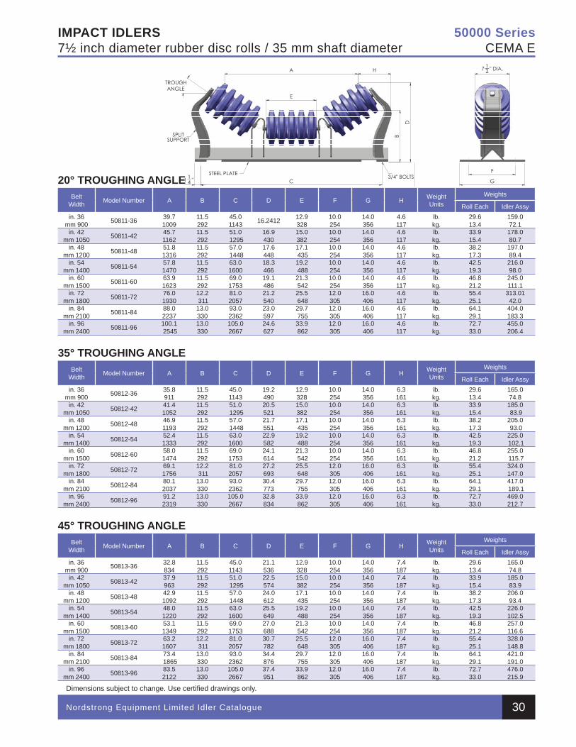
IMPACT IDLERS7½ inch diameter rubber disc rolls / 35 mm shaft diameter
Nordstrong Equipment Limited Idler Catalogue
Dimensions subject to change. Use certifi ed drawings only.
50000 SeriesCEMA E
20° TROUGHING ANGLEBelt
Width Model Number A B C D E F G H Weight Units
Weights
Roll Each Idler Assyin. 36
mm 900 50811-36 39.71009
11.5 292
45.01143 16.2412 12.9
32810.0254
14.0356
4.6117
lb.kg.
29.613.4
159.072.1
in. 42mm 1050 50811-42 45.7
116211.5 292
51.0 1295
16.9430
15.0382
10.0254
14.0356
4.6117
lb.kg.
33.915.4
178.080.7
in. 48mm 1200 50811-48 51.8
131611.5 292
57.0 1448
17.6448
17.1 435
10.0254
14.0356
4.6117
lb.kg.
38.217.3
197.089.4
in. 54mm 1400 50811-54 57.8
147011.5 292
63.01600
18.3466
19.2 488
10.0254
14.0356
4.6117
lb.kg.
42.519.3
216.098.0
in. 60mm 1500 50811-60 63.9
162311.5 292
69.01753
19.1486
21.3 542
10.0254
14.0356
4.6117
lb.kg.
46.821.2
245.0111.1
in. 72mm 1800 50811-72 76.0
193012.2 311
81.02057
21.2540
25.5 648
12.0305
16.0406
4.6117
lb.kg.
55.425.1
313.0142.0
in. 84 mm 2100 50811-84 88.0
223713.0330
93.02362
23.0597
29.7 755
12.0305
16.0406
4.6117
lb.kg.
64.129.1
404.0183.3
in. 96mm 2400 50811-96 100.1
254513.0330
105.02667
24.6627
33.9 862
12.0305
16.0406
4.6117
lb.kg.
72.733.0
455.0206.4
35° TROUGHING ANGLEBelt
Width Model Number A B C D E F G H Weight Units
Weights
Roll Each Idler Assyin. 36
mm 900 50812-36 35.8911
11.5 292
45.01143
19.2490
12.9328
10.0254
14.0356
6.3161
lb.kg.
29.613.4
165.074.8
in. 42mm 1050 50812-42 41.4
105211.5 292
51.0 1295
20.5521
15.0382
10.0254
14.0356
6.3161
lb.kg.
33.915.4
185.0 83.9
in. 48mm 1200 50812-48 46.9
119311.5 292
57.0 1448
21.7551
17.1 435
10.0254
14.0356
6.3161
lb.kg.
38.217.3
205.0 93.0
in. 54mm 1400 50812-54 52.4
133311.5 292
63.01600
22.9582
19.2 488
10.0254
14.0356
6.3161
lb.kg.
42.519.3
225.0 102.1
in. 60mm 1500 50812-60 58.0
147411.5 292
69.01753
24.1614
21.3 542
10.0254
14.0356
6.3161
lb.kg.
46.821.2
255.0 115.7
in. 72mm 1800 50812-72 69.1
175612.2 311
81.02057
27.2693
25.5 648
12.0305
16.0406
6.3161
lb.kg.
55.425.1
324.0147.0
in. 84 mm 2100 50812-84 80.1
203713.0330
93.02362
30.4773
29.7 755
12.0305
16.0406
6.3161
lb.kg.
64.129.1
417.0 189.1
in. 96mm 2400 50812-96 91.2
231913.0330
105.02667
32.8834
33.9 862
12.0305
16.0406
6.3161
lb.kg.
72.733.0
469.0212.7
45° TROUGHING ANGLEBelt
Width Model Number A B C D E F G H Weight Units
Weights
Roll Each Idler Assyin. 36
mm 900 50813-36 32.8834
11.5 292
45.01143
21.1536
12.9328
10.0254
14.0356
7.4187
lb.kg.
29.613.4
165.074.8
in. 42mm 1050 50813-42 37.9
96311.5 292
51.0 1295
22.5574
15.0382
10.0254
14.0356
7.4187
lb.kg.
33.915.4
185.083.9
in. 48mm 1200 50813-48 42.9
109211.5 292
57.0 1448
24.0612
17.1 435
10.0254
14.0356
7.4187
lb.kg.
38.217.3
206.093.4
in. 54mm 1400 50813-54 48.0
122011.5 292
63.01600
25.5649
19.2 488
10.0254
14.0356
7.4187
lb.kg.
42.519.3
226.0102.5
in. 60mm 1500 50813-60 53.1
134911.5 292
69.01753
27.0688
21.3 542
10.0254
14.0356
7.4187
lb.kg.
46.821.2
257.0116.6
in. 72mm 1800 50813-72 63.2
160712.2 311
81.02057
30.7782
25.5 648
12.0305
16.0406
7.4187
lb.kg.
55.425.1
328.0148.8
in. 84 mm 2100 50813-84 73.4
186513.0330
93.02362
34.4876
29.7 755
12.0305
16.0406
7.4187
lb.kg.
64.129.1
421.0191.0
in. 96mm 2400 50813-96 83.5
212213.0330
105.02667
37.4951
33.9 862
12.0305
16.0406
7.4187
lb.kg.
72.733.0
476.0215.9
30
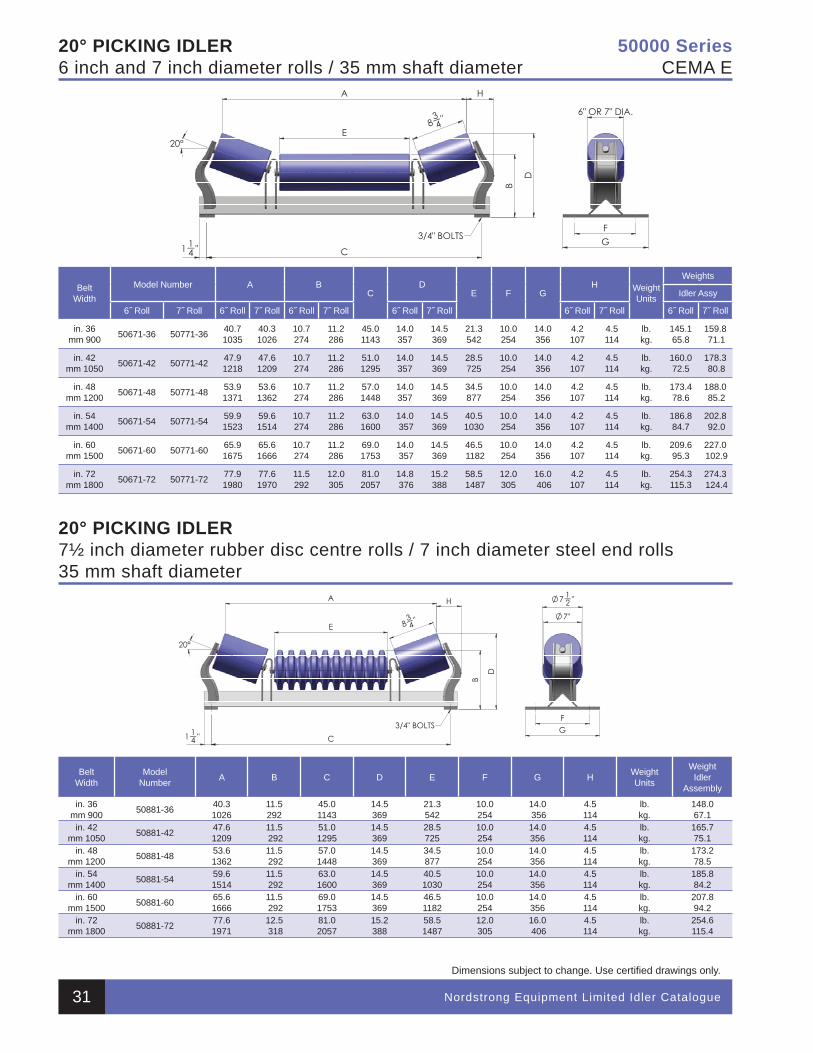
Nordstrong Equipment Limited Idler Catalogue
Dimensions subject to change. Use certifi ed drawings only.
50000 SeriesCEMA E
20° PICKING IDLER6 inch and 7 inch diameter rolls / 35 mm shaft diameter
BeltWidth
Model Number A BC
DE F G
H Weight Units
Weights
Idler Assy
6˝ Roll 7˝ Roll 6˝ Roll 7˝ Roll 6˝ Roll 7˝ Roll 6˝ Roll 7˝ Roll 6˝ Roll 7˝ Roll 6˝ Roll 7˝ Roll
in. 36mm 900 50671-36 50771-36 40.7
103540.31026
10.7274
11.2286
45.01143
14.0357
14.5369
21.3542
10.0254
14.0356
4.2 107
4.5 114
lb.kg.
145.165.8
159.8 71.1
in. 42mm 1050 50671-42 50771-42 47.9
121847.61209
10.7274
11.2286
51.01295
14.0357
14.5369
28.5725
10.0254
14.0356
4.2 107
4.5 114
lb.kg.
160.072.5
178.3 80.8
in. 48mm 1200 50671-48 50771-48 53.9
137153.61362
10.7274
11.2286
57.01448
14.0357
14.5369
34.5877
10.0254
14.0356
4.2 107
4.5 114
lb.kg.
173.478.6
188.0 85.2
in. 54mm 1400 50671-54 50771-54 59.9
152359.61514
10.7274
11.2286
63.01600
14.0 357
14.5369
40.51030
10.0254
14.0356
4.2 107
4.5 114
lb.kg.
186.884.7
202.8 92.0
in. 60mm 1500 50671-60 50771-60 65.9
167565.61666
10.7274
11.2286
69.01753
14.0 357
14.5369
46.5 1182
10.0254
14.0356
4.2 107
4.5 114
lb.kg.
209.695.3
227.0 102.9
in. 72mm 1800 50671-72 50771-72 77.9
198077.6 1970
11.5292
12.0305
81.02057
14.8 376
15.2388
58.5 1487
12.0305
16.0 406
4.2 107
4.5 114
lb.kg.
254.3115.3
274.3 124.4
20° PICKING IDLER7½ inch diameter rubber disc centre rolls / 7 inch diameter steel end rolls35 mm shaft diameter
BeltWidth
ModelNumber A B C D E F G H Weight
Units
WeightIdler
Assembly
in. 36mm 900 50881-36 40.3
102611.5292
45.01143
14.5369
21.3542
10.0254
14.0 356
4.5114
lb.kg.
148.067.1
in. 42mm 1050 50881-42 47.6
120911.5 292
51.01295
14.5369
28.5725
10.0254
14.0356
4.5114
lb.kg.
165.775.1
in. 48mm 1200 50881-48 53.6
136211.5 292
57.01448
14.5369
34.5877
10.0254
14.0356
4.5114
lb.kg.
173.278.5
in. 54mm 1400 50881-54 59.6
151411.5 292
63.01600
14.5369
40.51030
10.0254
14.0356
4.5114
lb.kg.
185.884.2
in. 60mm 1500 50881-60 65.6
166611.5 292
69.01753
14.5369
46.51182
10.0254
14.0356
4.5114
lb.kg.
207.894.2
in. 72mm 1800 50881-72 77.6
197112.5 318
81.02057
15.2388
58.51487
12.0305
16.0 406
4.5114
lb.kg.
254.6115.4
31
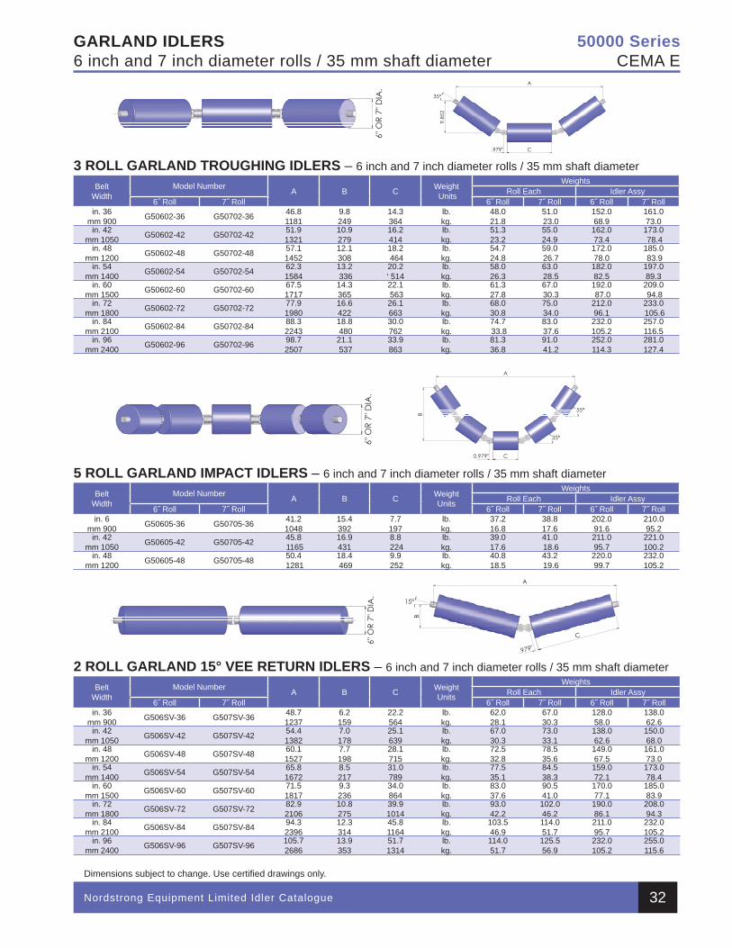
Nordstrong Equipment Limited Idler Catalogue
Dimensions subject to change. Use certifi ed drawings only.
50000 SeriesCEMA E
GARLAND IDLERS6 inch and 7 inch diameter rolls / 35 mm shaft diameter
3 ROLL GARLAND TROUGHING IDLERS – 6 inch and 7 inch diameter rolls / 35 mm shaft diameterBelt
WidthModel Number A B C Weight
Units
WeightsRoll Each Idler Assy
6˝ Roll 7˝ Roll 6˝ Roll 7˝ Roll 6˝ Roll 7˝ Rollin. 36
mm 900 G50602-36 G50702-36 46.8 1181
9.8249
14.3 364
lb.kg.
48.0 21.8
51.0 23.0
152.0 68.9
161.0 73.0
in. 42mm 1050 G50602-42 G50702-42 51.9
132110.9279
16.2 414
lb.kg.
51.3 23.2
55.0 24.9
162.0 73.4
173.0 78.4
in. 48mm 1200 G50602-48 G50702-48 57.1
145212.1 308
18.2 464
lb.kg.
54.724.8
59.0 26.7
172.0 78.0
185.0 83.9
in. 54mm 1400 G50602-54 G50702-54 62.3
158413.2 336
20.2 ‘ 514
lb.kg.
58.0 26.3
63.0 28.5
182.0 82.5
197.0 89.3
in. 60mm 1500 G50602-60 G50702-60 67.5
171714.3 365
22.1 563
lb.kg.
61.327.8
67.0 30.3
192.0 87.0
209.0 94.8
in. 72mm 1800 G50602-72 G50702-72 77.9
198016.6 422
26.1 663
lb.kg.
68.0 30.8
75.0 34.0
212.0 96.1
233.0 105.6
in. 84mm 2100 G50602-84 G50702-84 88.3
224318.8 480
30.0 762
lb.kg.
74.7 33.8
83.0 37.6
232.0 105.2
257.0 116.5
in. 96mm 2400 G50602-96 G50702-96 98.7
250721.1 537
33.9 863
lb.kg.
81.3 36.8
91.0 41.2
252.0 114.3
281.0 127.4
5 ROLL GARLAND IMPACT IDLERS – 6 inch and 7 inch diameter rolls / 35 mm shaft diameterBelt
WidthModel Number A B C Weight
Units
WeightsRoll Each Idler Assy
6˝ Roll 7˝ Roll 6˝ Roll 7˝ Roll 6˝ Roll 7˝ Rollin. 6
mm 900 G50605-36 G50705-36 41.2 1048
15.4 392
7.7 197
lb.kg.
37.2 16.8
38.8 17.6
202.091.6
210.095.2
in. 42mm 1050 G50605-42 G50705-42 45.8
116516.9 431
8.8 224
lb.kg.
39.017.6
41.0 18.6
211.095.7
221.0100.2
in. 48mm 1200 G50605-48 G50705-48 50.4
128118.4 469
9.9 252
lb.kg.
40.818.5
43.2 19.6
220.099.7
232.0105.2
2 ROLL GARLAND 15° VEE RETURN IDLERS – 6 inch and 7 inch diameter rolls / 35 mm shaft diameterBelt
WidthModel Number A B C Weight
Units
WeightsRoll Each Idler Assy
6˝ Roll 7˝ Roll 6˝ Roll 7˝ Roll 6˝ Roll 7˝ Rollin. 36
mm 900 G506SV-36 G507SV-36 48.7 1237
6.2159
22.2564
lb.kg.
62.0 28.1
67.0 30.3
128.0 58.0
138.0 62.6
in. 42mm 1050 G506SV-42 G507SV-42 54.4
13827.0178
25.1 639
lb.kg.
67.0 30.3
73.0 33.1
138.0 62.6
150.0 68.0
in. 48mm 1200 G506SV-48 G507SV-48 60.1
15277.7198
28.1 715
lb.kg.
72.5 32.8
78.5 35.6
149.0 67.5
161.0 73.0
in. 54mm 1400 G506SV-54 G507SV-54 65.8
16728.5217
31.0 789
lb.kg.
77.5 35.1
84.5 38.3
159.0 72.1
173.0 78.4
in. 60mm 1500 G506SV-60 G507SV-60 71.5
18179.3236
34.0 864
lb.kg.
83.0 37.6
90.5 41.0
170.0 77.1
185.0 83.9
in. 72mm 1800 G506SV-72 G507SV-72 82.9
210610.8275
39.9 1014
lb.kg.
93.0 42.2
102.0 46.2
190.0 86.1
208.0 94.3
in. 84mm 2100 G506SV-84 G507SV-84 94.3
239612.3314
45.8 1164
lb.kg.
103.5 46.9
114.0 51.7
211.0 95.7
232.0 105.2
in. 96mm 2400 G506SV-96 G507SV-96 105.7
268613.9353
51.7 1314
lb.kg.
114.0 51.7
125.5 56.9
232.0 105.2
255.0115.6
32
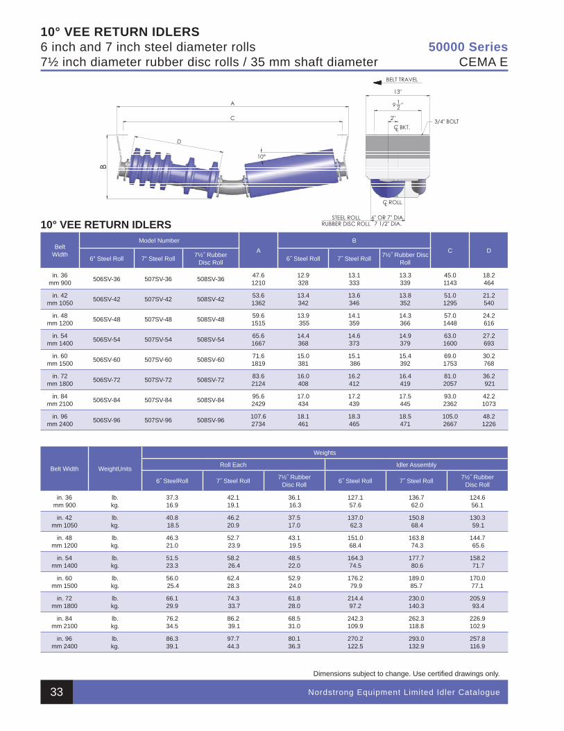
Nordstrong Equipment Limited Idler Catalogue
Dimensions subject to change. Use certifi ed drawings only.
50000 SeriesCEMA E
10° VEE RETURN IDLERS6 inch and 7 inch steel diameter rolls7½ inch diameter rubber disc rolls / 35 mm shaft diameter
10° VEE RETURN IDLERS
BeltWidth
Model NumberA
BC D
6” Steel Roll 7” Steel Roll 7½˝ RubberDisc Roll 6˝ Steel Roll 7˝ Steel Roll 7½˝ Rubber Disc
Roll
in. 36mm 900 506SV-36 507SV-36 508SV-36 47.6
121012.9 328
13.1333
13.3 339
45.01143
18.2464
in. 42mm 1050 506SV-42 507SV-42 508SV-42 53.6
136213.4 342
13.6346
13.8 352
51.01295
21.2 540
in. 48mm 1200 506SV-48 507SV-48 508SV-48 59.6
151513.9 355
14.1 359
14.3 366
57.01448
24.2 616
in. 54mm 1400 506SV-54 507SV-54 508SV-54 65.6
166714.4 368
14.6 373
14.9 379
63.01600
27.2 693
in. 60mm 1500 506SV-60 507SV-60 508SV-60 71.6
181915.0 381
15.1 386
15.4 392
69.01753
30.2 768
in. 72mm 1800 506SV-72 507SV-72 508SV-72 83.6
212416.0 408
16.2 412
16.4 419
81.02057
36.2 921
in. 84 mm 2100 506SV-84 507SV-84 508SV-84 95.6
242917.0 434
17.2 439
17.5445
93.0 2362
42.2 1073
in. 96mm 2400 506SV-96 507SV-96 508SV-96 107.6
273418.1 461
18.3465
18.5 471
105.02667
48.2 1226
Belt Width WeightUnits
Weights
Roll Each Idler Assembly
6˝ SteelRoll 7˝ Steel Roll 7½˝ RubberDisc Roll 6˝ Steel Roll 7˝ Steel Roll 7½˝ Rubber
Disc Roll
in. 36mm 900
lb.kg.
37.316.9
42.1 19.1
36.1 16.3
127.1 57.6
136.7 62.0
124.6 56.1
in. 42mm 1050
lb.kg.
40.8 18.5
46.220.9
37.517.0
137.0 62.3
150.8 68.4
130.3 59.1
in. 48mm 1200
lb.kg.
46.3 21.0
52.7 23.9
43.1 19.5
151.0 68.4
163.8 74.3
144.7 65.6
in. 54mm 1400
lb.kg.
51.5 23.3
58.2 26.4
48.522.0
164.3 74.5
177.7 80.6
158.2 71.7
in. 60mm 1500
lb.kg.
56.0 25.4
62.4 28.3
52.9 24.0
176.2 79.9
189.0 85.7
170.0 77.1
in. 72mm 1800
lb.kg.
66.129.9
74.3 33.7
61.8 28.0
214.4 97.2
230.0 140.3
205.9 93.4
in. 84 mm 2100
lb.kg.
76.234.5
86.2 39.1
68.5 31.0
242.3 109.9
262.3118.8
226.9 102.9
in. 96mm 2400
lb.kg.
86.339.1
97.7 44.3
80.1 36.3
270.2 122.5
293.0132.9
257.8116.9
33
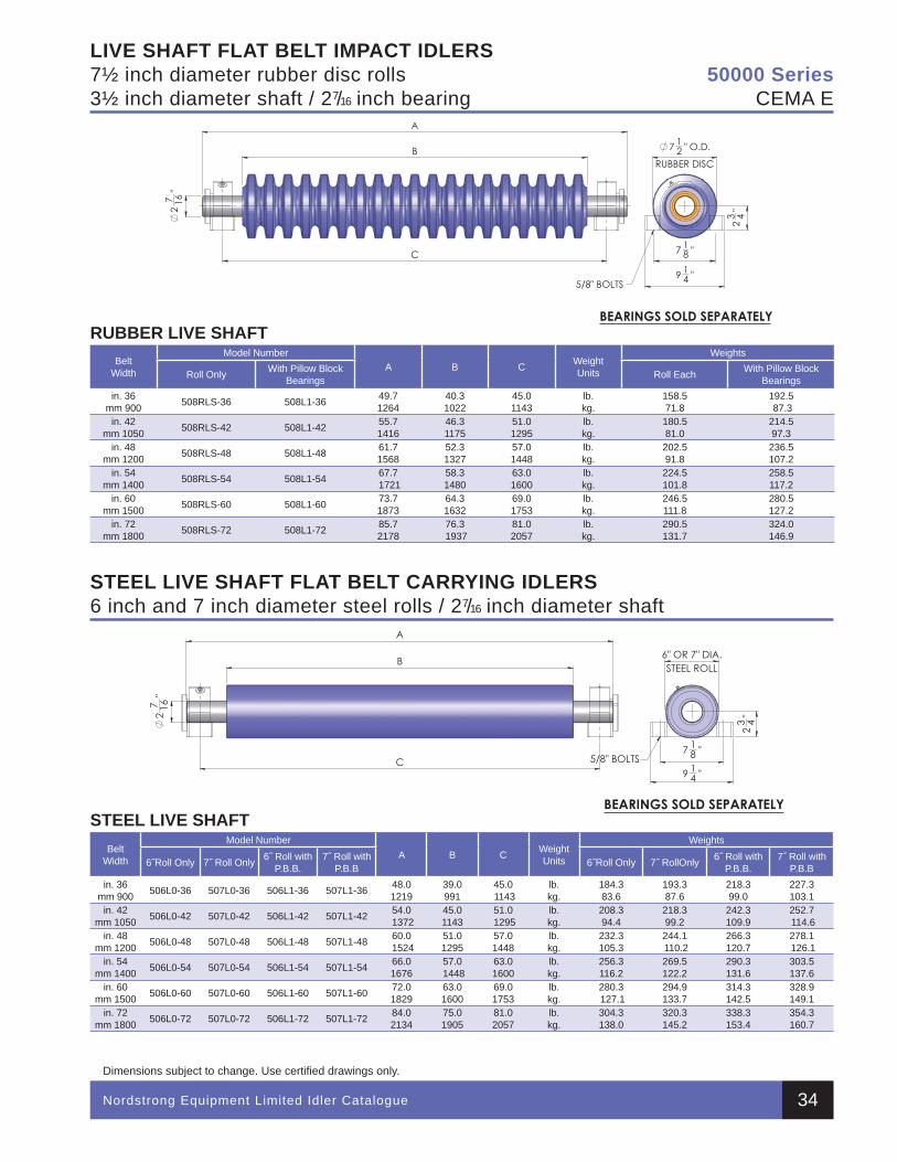
Nordstrong Equipment Limited Idler Catalogue
Dimensions subject to change. Use certifi ed drawings only.
50000 SeriesCEMA E
LIVE SHAFT FLAT BELT IMPACT IDLERS7½ inch diameter rubber disc rolls3½ inch diameter shaft / 27/16 inch bearing
STEEL LIVE SHAFT FLAT BELT CARRYING IDLERS6 inch and 7 inch diameter steel rolls / 27/16 inch diameter shaft
RUBBER LIVE SHAFTBelt
Width
Model NumberA B C Weight
Units
Weights
Roll Only With Pillow Block Bearings Roll Each With Pillow Block
Bearingsin. 36
mm 900 508RLS-36 508L1-36 49.7 1264
40.31022
45.01143
lb.kg.
158.571.8
192.5 87.3
in. 42mm 1050 508RLS-42 508L1-42 55.7
141646.31175
51.01295
lb.kg.
180.581.0
214.597.3
in. 48mm 1200 508RLS-48 508L1-48 61.7
156852.31327
57.01448
lb.kg.
202.591.8
236.5107.2
in. 54mm 1400 508RLS-54 508L1-54 67.7
172158.31480
63.01600
lb.kg.
224.5101.8
258.5117.2
in. 60mm 1500 508RLS-60 508L1-60 73.7
187364.31632
69.01753
lb.kg.
246.5 111.8
280.5 127.2
in. 72mm 1800 508RLS-72 508L1-72 85.7
217876.3 1937
81.02057
lb.kg.
290.5 131.7
324.0 146.9
STEEL LIVE SHAFTBelt
Width
Model NumberA B C Weight
Units
Weights
6˝Roll Only 7˝ Roll Only 6˝ Roll with P.B.B.
7˝ Roll with P.B.B 6˝Roll Only 7˝ RollOnly 6˝ Roll with
P.B.B.7˝ Roll with
P.B.Bin. 36
mm 900 506L0-36 507L0-36 506L1-36 507L1-36 48.0 1219
39.0 991
45.0 1143
lb.kg.
184.3 83.6
193.3 87.6
218.3 99.0
227.3 103.1
in. 42mm 1050 506L0-42 507L0-42 506L1-42 507L1-42 54.0
137245.01143
51.0 1295
lb.kg.
208.3 94.4
218.3 99.2
242.3 109.9
252.7 114.6
in. 48mm 1200 506L0-48 507L0-48 506L1-48 507L1-48 60.0
152451.01295
57.01448
lb.kg.
232.3 105.3
244.1 110.2
266.3 120.7
278.1 126.1
in. 54mm 1400 506L0-54 507L0-54 506L1-54 507L1-54 66.0
167657.0 1448
63.01600
lb.kg.
256.3 116.2
269.5122.2
290.3 131.6
303.5 137.6
in. 60mm 1500 506L0-60 507L0-60 506L1-60 507L1-60 72.0
182963.0 1600
69.01753
lb.kg.
280.3 127.1
294.9 133.7
314.3 142.5
328.9 149.1
in. 72mm 1800 506L0-72 507L0-72 506L1-72 507L1-72 84.0
213475.0 1905
81.02057
lb.kg.
304.3138.0
320.3 145.2
338.3 153.4
354.3 160.7
34
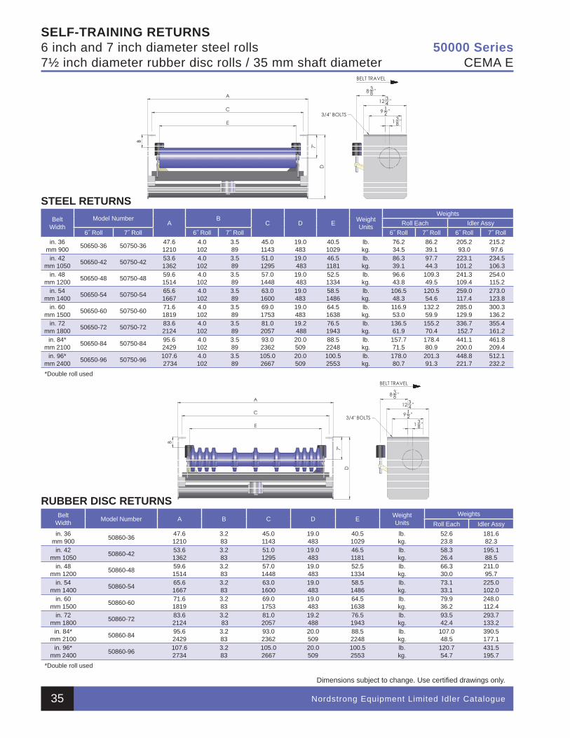
Nordstrong Equipment Limited Idler Catalogue
Dimensions subject to change. Use certifi ed drawings only.
SELF-TRAINING RETURNS6 inch and 7 inch diameter steel rolls7½ inch diameter rubber disc rolls / 35 mm shaft diameter
STEEL RETURNSBelt
WidthModel Number
AB
C D E WeightUnits
WeightsRoll Each Idler Assy
6˝ Roll 7˝ Roll 6˝ Roll 7˝ Roll 6˝ Roll 7˝ Roll 6˝ Roll 7˝ Rollin. 36
mm 900 50650-36 50750-36 47.6 1210
4.0102
3.589
45.01143
19.0483
40.51029
lb.kg.
76.2 34.5
86.239.1
205.293.0
215.297.6
in. 42mm 1050 50650-42 50750-42 53.6
13624.0102
3.589
51.01295
19.0 483
46.51181
lb.kg.
86.339.1
97.744.3
223.1101.2
234.5106.3
in. 48mm 1200 50650-48 50750-48 59.6
15144.0102
3.589
57.01448
19.0 483
52.51334
lb.kg.
96.643.8
109.349.5
241.3109.4
254.0115.2
in. 54mm 1400 50650-54 50750-54 65.6
16674.0102
3.589
63.01600
19.0483
58.51486
lb.kg.
106.548.3
120.554.6
259.0 117.4
273.0 123.8
in. 60mm 1500 50650-60 50750-60 71.6
18194.0102
3.589
69.01753
19.0483
64.51638
lb.kg.
116.953.0
132.259.9
285.0129.9
300.3 136.2
in. 72mm 1800 50650-72 50750-72 83.6
21244.0102
3.589
81.02057
19.2 488
76.5 1943
lb.kg.
136.5 61.9
155.270.4
336.7 152.7
355.4161.2
in. 84* mm 2100 50650-84 50750-84 95.6
24294.0102
3.589
93.02362
20.0 509
88.5 2248
lb.kg.
157.771.5
178.480.9
441.1200.0
461.8 209.4
in. 96*mm 2400 50650-96 50750-96 107.6
27344.0102
3.589
105.02667
20.0 509
100.52553
lb.kg.
178.0 80.7
201.391.3
448.8 221.7
512.1232.2
*Double roll used
RUBBER DISC RETURNSBelt
Width Model Number A B C D E WeightUnits
WeightsRoll Each Idler Assy
in. 36mm 900 50860-36 47.6
12103.283
45.0 1143
19.0 483
40.5 1029
lb.kg.
52.6 23.8
181.6 82.3
in. 42mm 1050 50860-42 53.6
13623.283
51.0 1295
19.0 483
46.5 1181
lb.kg.
58.3 26.4
195.1 88.5
in. 48mm 1200 50860-48 59.6
15143.283
57.0 1448
19.0 483
52.5 1334
lb.kg.
66.3 30.0
211.0 95.7
in. 54mm 1400 50860-54 65.6
16673.283
63.0 1600
19.0 483
58.5 1486
lb.kg.
73.1 33.1
225.0 102.0
in. 60mm 1500 50860-60 71.6
18193.283
69.0 1753
19.0 483
64.5 1638
lb.kg.
79.9 36.2
248.0 112.4
in. 72mm 1800 50860-72 83.6
21243.2 83
81.0 2057
19.2488
76.5 1943
lb.kg.
93.5 42.4
293.7 133.2
in. 84* mm 2100 50860-84 95.6
24293.283
93.0 2362
20.0509
88.52248
lb.kg.
107.0 48.5
390.5 177.1
in. 96*mm 2400 50860-96 107.6
27343.283
105.0 2667
20.0 509
100.5 2553
lb.kg.
120.7 54.7
431.5 195.7
*Double roll used
50000 SeriesCEMA E
35
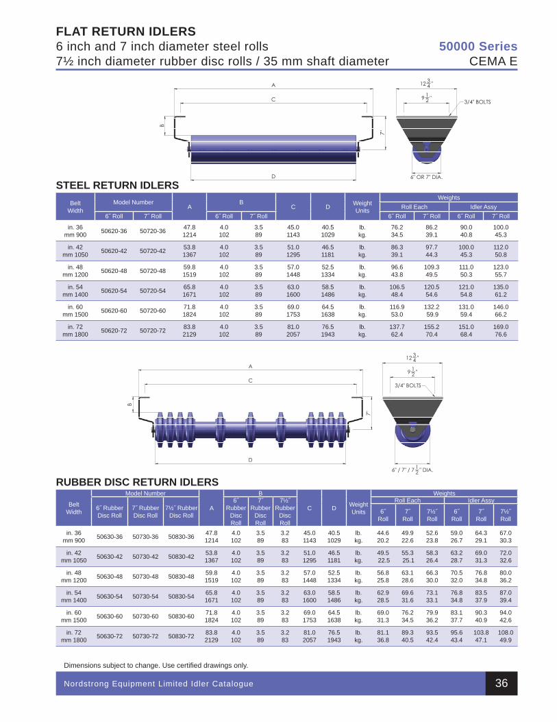
Nordstrong Equipment Limited Idler Catalogue
Dimensions subject to change. Use certifi ed drawings only.
FLAT RETURN IDLERS6 inch and 7 inch diameter steel rolls7½ inch diameter rubber disc rolls / 35 mm shaft diameter
STEEL RETURN IDLERSBelt
WidthModel Number
AB
C D WeightUnits
WeightsRoll Each Idler Assy
6˝ Roll 7˝ Roll 6˝ Roll 7˝ Roll 6˝ Roll 7˝ Roll 6˝ Roll 7˝ Roll
in. 36mm 900 50620-36 50720-36 47.8
12144.0102
3.589
45.01143
40.51029
lb.kg.
76.2 34.5
86.239.1
90.0 40.8
100.0 45.3
in. 42mm 1050 50620-42 50720-42 53.8
13674.0102
3.589
51.01295
46.51181
lb.kg.
86.339.1
97.744.3
100.0 45.3
112.050.8
in. 48mm 1200 50620-48 50720-48 59.8
15194.0102
3.589
57.01448
52.51334
lb.kg.
96.643.8
109.349.5
111.0 50.3
123.055.7
in. 54mm 1400 50620-54 50720-54 65.8
16714.0102
3.589
63.01600
58.51486
lb.kg.
106.548.4
120.554.6
121.054.8
135.061.2
in. 60mm 1500 50620-60 50720-60 71.8
18244.0102
3.589
69.01753
64.51638
lb.kg.
116.953.0
132.2 59.9
131.059.4
146.0 66.2
in. 72mm 1800 50620-72 50720-72 83.8
21294.0102
3.589
81.02057
76.5 1943
lb.kg.
137.762.4
155.270.4
151.068.4
169.076.6
RUBBER DISC RETURN IDLERS
BeltWidth
Model Number
A
B
C D Weight Units
Weights
6˝ Rubber Disc Roll
7˝ Rubber Disc Roll
7½˝ Rubber Disc Roll
6˝Rubber
Disc Roll
7˝Rubber
Disc Roll
7½˝ Rubber
Disc Roll
Roll Each Idler Assy
6˝Roll
7˝Roll
7½˝Roll
6˝Roll
7˝Roll
7½˝Roll
in. 36mm 900 50630-36 50730-36 50830-36 47.8
12144.0 102
3.5 89
3.283
45.01143
40.51029
lb.kg.
44.620.2
49.922.6
52.6 23.8
59.026.7
64.3 29.1
67.030.3
in. 42mm 1050 50630-42 50730-42 50830-42 53.8
13674.0 102
3.5 89
3.283
51.0 1295
46.51181
lb.kg.
49.5 22.5
55.3 25.1
58.326.4
63.2 28.7
69.0 31.3
72.032.6
in. 48mm 1200 50630-48 50730-48 50830-48 59.8
15194.0102
3.5 89
3.283
57.01448
52.51334
lb.kg.
56.825.8
63.128.6
66.330.0
70.532.0
76.8 34.8
80.036.2
in. 54mm 1400 50630-54 50730-54 50830-54 65.8
16714.0 102
3.5 89
3.283
63.0 1600
58.5 1486
lb.kg.
62.928.5
69.631.6
73.133.1
76.834.8
83.5 37.9
87.039.4
in. 60mm 1500 50630-60 50730-60 50830-60 71.8
18244.0 102
3.5 89
3.283
69.01753
64.5 1638
lb.kg.
69.031.3
76.2 34.5
79.936.2
83.137.7
90.340.9
94.0 42.6
in. 72mm 1800 50630-72 50730-72 50830-72 83.8
21294.0 102
3.5 89
3.283
81.0 2057
76.5 1943
lb.kg.
81.136.8
89.340.5
93.542.4
95.643.4
103.847.1
108.0 49.9
50000 SeriesCEMA E
36
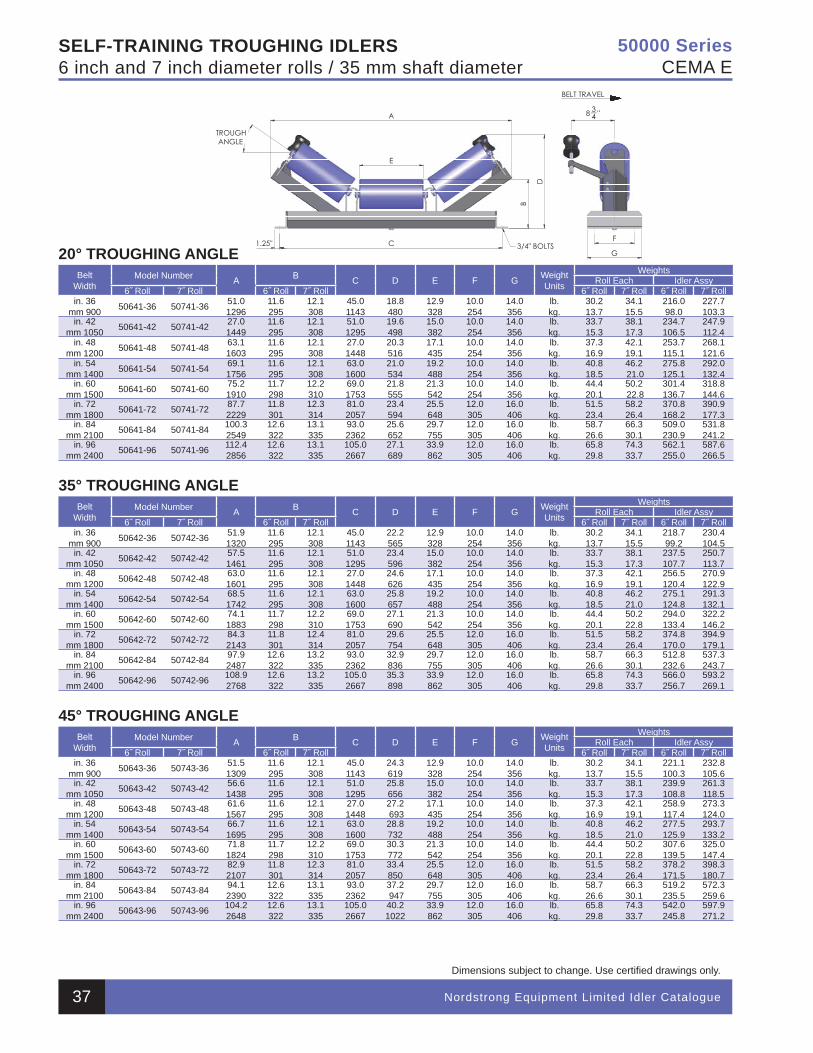
Nordstrong Equipment Limited Idler Catalogue
Dimensions subject to change. Use certifi ed drawings only.
SELF-TRAINING TROUGHING IDLERS6 inch and 7 inch diameter rolls / 35 mm shaft diameter
20° TROUGHING ANGLEBelt
WidthModel Number A B C D E F G Weight
Units
WeightsRoll Each Idler Assy
6˝ Roll 7˝ Roll 6˝ Roll 7˝ Roll 6˝ Roll 7˝ Roll 6˝ Roll 7˝ Rollin. 36
mm 900 50641-36 50741-36 51.0 1296
11.6295
12.1308
45.0 1143
18.8480
12.9328
10.0254
14.0356
lb.kg.
30.213.7
34.115.5
216.098.0
227.7 103.3
in. 42mm 1050 50641-42 50741-42 27.0
144911.6295
12.1 308
51.0 1295
19.6 498
15.0382
10.0254
14.0356
lb.kg.
33.715.3
38.117.3
234.7 106.5
247.9 112.4
in. 48mm 1200 50641-48 50741-48 63.1
160311.6295
12.1 308
27.01448
20.3 516
17.1435
10.0254
14.0356
lb.kg.
37.316.9
42.119.1
253.7 115.1
268.1121.6
in. 54mm 1400 50641-54 50741-54 69.1
175611.6295
12.1 308
63.01600
21.0 534
19.2488
10.0254
14.0356
lb.kg.
40.818.5
46.2 21.0
275.8 125.1
292.0 132.4
in. 60mm 1500 50641-60 50741-60 75.2
191011.7298
12.2310
69.01753
21.8 555
21.3542
10.0254
14.0356
lb.kg.
44.420.1
50.2 22.8
301.4 136.7
318.8 144.6
in. 72mm 1800 50641-72 50741-72 87.7
222911.8301
12.3314
81.02057
23.4 594
25.5648
12.0305
16.0406
lb.kg.
51.523.4
58.226.4
370.8 168.2
390.9 177.3
in. 84 mm 2100 50641-84 50741-84 100.3
254912.6322
13.1 335
93.02362
25.6 652
29.7755
12.0305
16.0406
lb.kg.
58.726.6
66.330.1
509.0 230.9
531.8 241.2
in. 96mm 2400 50641-96 50741-96 112.4
285612.6322
13.1335
105.02667
27.1 689
33.9862
12.0305
16.0406
lb.kg.
65.829.8
74.333.7
562.1 255.0
587.6 266.5
35° TROUGHING ANGLEBelt
WidthModel Number A B C D E F G Weight
Units
WeightsRoll Each Idler Assy
6˝ Roll 7˝ Roll 6˝ Roll 7˝ Roll 6˝ Roll 7˝ Roll 6˝ Roll 7˝ Rollin. 36
mm 900 50642-36 50742-36 51.9 1320
11.6295
12.1308
45.0 1143
22.2565
12.9328
10.0254
14.0356
lb.kg.
30.213.7
34.115.5
218.7 99.2
230.4104.5
in. 42mm 1050 50642-42 50742-42 57.5
146111.6295
12.1 308
51.0 1295
23.4 596
15.0382
10.0254
14.0356
lb.kg.
33.715.3
38.117.3
237.5 107.7
250.7113.7
in. 48mm 1200 50642-48 50742-48 63.0
160111.6295
12.1 308
27.01448
24.6626
17.1435
10.0254
14.0356
lb.kg.
37.316.9
42.119.1
256.5 120.4
270.9 122.9
in. 54mm 1400 50642-54 50742-54 68.5
174211.6295
12.1 308
63.01600
25.8657
19.2488
10.0254
14.0356
lb.kg.
40.818.5
46.221.0
275.1 124.8
291.3132.1
in. 60mm 1500 50642-60 50742-60 74.1
188311.7298
12.2310
69.01753
27.1690
21.3542
10.0254
14.0356
lb.kg.
44.420.1
50.222.8
294.0 133.4
322.2146.2
in. 72mm 1800 50642-72 50742-72 84.3
214311.8301
12.4314
81.02057
29.6 754
25.5648
12.0305
16.0406
lb.kg.
51.523.4
58.226.4
374.8 170.0
394.9 179.1
in. 84 mm 2100 50642-84 50742-84 97.9
248712.6322
13.2 335
93.02362
32.9836
29.7755
12.0305
16.0406
lb.kg.
58.726.6
66.330.1
512.8 232.6
537.3243.7
in. 96mm 2400 50642-96 50742-96 108.9
276812.6322
13.2335
105.02667
35.3 898
33.9862
12.0305
16.0406
lb.kg.
65.829.8
74.333.7
566.0 256.7
593.2269.1
45° TROUGHING ANGLEBelt
WidthModel Number A B C D E F G Weight
Units
WeightsRoll Each Idler Assy
6˝ Roll 7˝ Roll 6˝ Roll 7˝ Roll 6˝ Roll 7˝ Roll 6˝ Roll 7˝ Rollin. 36
mm 900 50643-36 50743-36 51.51309
11.6295
12.1308
45.0 1143
24.3 619
12.9328
10.0254
14.0356
lb.kg.
30.213.7
34.115.5
221.1 100.3
232.8105.6
in. 42mm 1050 50643-42 50743-42 56.6
143811.6295
12.1 308
51.0 1295
25.8 656
15.0382
10.0254
14.0356
lb.kg.
33.715.3
38.117.3
239.9108.8
261.3 118.5
in. 48mm 1200 50643-48 50743-48 61.6
156711.6295
12.1 308
27.01448
27.2 693
17.1435
10.0254
14.0356
lb.kg.
37.316.9
42.119.1
258.9 117.4
273.3124.0
in. 54mm 1400 50643-54 50743-54 66.7
169511.6295
12.1 308
63.01600
28.8732
19.2488
10.0254
14.0356
lb.kg.
40.818.5
46.221.0
277.5 125.9
293.7 133.2
in. 60mm 1500 50643-60 50743-60 71.8
182411.7298
12.2310
69.01753
30.3 772
21.3542
10.0254
14.0356
lb.kg.
44.420.1
50.222.8
307.6 139.5
325.0147.4
in. 72mm 1800 50643-72 50743-72 82.9
210711.8301
12.3314
81.02057
33.4 850
25.5648
12.0305
16.0406
lb.kg.
51.523.4
58.226.4
378.2 171.5
398.3 180.7
in. 84 mm 2100 50643-84 50743-84 94.1
239012.6322
13.1 335
93.02362
37.2 947
29.7755
12.0305
16.0406
lb.kg.
58.726.6
66.330.1
519.2 235.5
572.3 259.6
in. 96mm 2400 50643-96 50743-96 104.2
264812.6322
13.1335
105.02667
40.21022
33.9862
12.0305
16.0406
lb.kg.
65.829.8
74.333.7
542.0 245.8
597.9271.2
50000 SeriesCEMA E
37
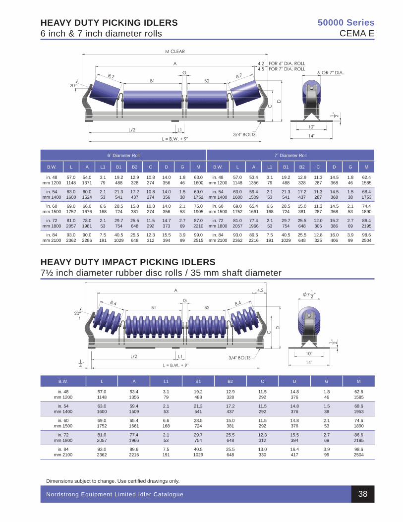
Nordstrong Equipment Limited Idler Catalogue
Dimensions subject to change. Use certifi ed drawings only.
HEAVY DUTY PICKING IDLERS6 inch & 7 inch diameter rolls
HEAVY DUTY IMPACT PICKING IDLERS7½ inch diameter rubber disc rolls / 35 mm shaft diameter
6˝ Diameter Roll 7˝ Diameter Roll
B.W. L A L1 B1 B2 C D G M B.W. L A L1 B1 B2 C D G M
in. 48mm 1200
57.0 1148
54.01371
3.179
19.2 488
12.9328
10.8274
14.0356
1.846
63.01600
in. 48mm 1200
57.01148
53.4 1356
3.1 79
19.2 488
12.9 328
11.3 287
14.5 368
1.8 46
62.4 1585
in. 54mm 1400
63.01600
60.0 1524
2.1 53
21.3541
17.2 437
10.8274
14.0 356
1.538
69.01752
in. 54mm 1400
63.01600
59.41509
2.1 53
21.3541
17.2 437
11.3 287
14.5 368
1.5 38
68.4 1753
in. 60mm 1500
69.01752
66.0 1676
6.6 168
28.5724
15.0381
10.8274
14.0356
2.153
75.01905
in. 60mm 1500
69.01752
65.41661
6.6168
28.5 724
15.0 381
11.3 287
14.5 368
2.1 53
74.4 1890
in. 72mm 1800
81.02057
78.0 1981
2.1 53
29.7754
25.5648
11.5 292
14.7 373
2.769
87.02210
in. 72mm 1800
81.02057
77.41966
2.1 53
29.7 754
25.5 648
12.0 305
15.2 386
2.7 69
86.4 2195
in. 84mm 2100
93.02362
90.0 2286
7.5 191
40.51029
25.5648
12.3 312
15.5 394
3.999
99.02515
in. 84mm 2100
93.02362
89.6 2216
7.5 191
40.5 1029
25.5 648
12.8 325
16.0 406
3.9 99
98.62504
B.W. L A L1 B1 B2 C D G M
in. 48mm 1200
57.0 1148
53.4 1356
3.179
19.2 488
12.9328
11.5 292
14.8 376
1.846
62.6 1585
in. 54mm 1400
63.01600
59.4 1509
2.1 53
21.3541
17.2 437
11.5 292
14.8 376
1.538
68.6 1953
in. 60mm 1500
69.01752
65.4 1661
6.6 168
28.5724
15.0381
11.5 292
14.8 376
2.153
74.6 1890
in. 72mm 1800
81.02057
77.4 1966
2.1 53
29.7754
25.5648
12.3 312
15.5 394
2.769
86.6 2195
in. 84mm 2100
93.02362
89.6 2216
7.5 191
40.51029
25.5648
13.0 330
16.4 417
3.999
98.6 2504
50000 SeriesCEMA E
38
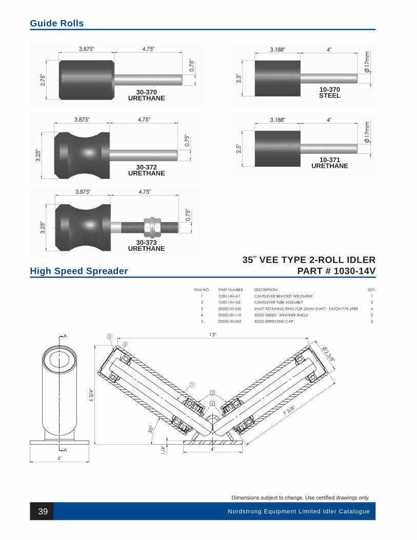
39 Nordstrong Equipment Limited Idler Catalogue
35˝ VEE TYPE 2-ROLL IDLERPART # 1030-14V
Dimensions subject to change. Use certifi ed drawings only.
Guide Rolls
High Speed Spreader
30-372URETHANE
30-370URETHANE
30-373URETHANE
10-371URETHANE
10-370STEEL
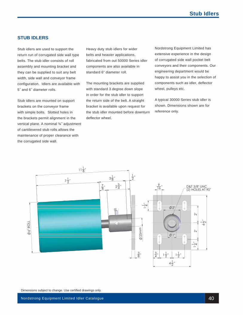
40
IMPACT BEDS
Nordstrong Equipment Limited Idler Catalogue
8200 Series
Dimensions subject to change. Use certifi ed drawings only.
Stub Idlers
STUB IDLERS
Stub idlers are used to support the
return run of corrugated side wall type
belts. The stub idler consists of roll
assembly and mounting bracket and
they can be supplied to suit any belt
width, side wall and conveyor frame
configuration. Idlers are available with
5˝ and 6˝ diameter rolls.
Stub idlers are mounted on support
brackets on the conveyor frame
with simple bolts. Slotted holes in
the brackets permit alignment in the
vertical plane. A nominal ¾˝ adjustment
of cantilevered stub rolls allows the
maintenance of proper clearance with
the corrugated side wall.
Heavy duty stub idlers for wider
belts and heavier applications,
fabricated from out 50000 Series idler
components are also available in
standard 6” diameter roll.
The mounting brackets are supplied
with standard 3 degree down slope
in order for the stub idler to support
the return side of the belt. A straight
bracket is available upon request for
the stub idler mounted before downturn
deflector wheel.
Nordstrong Equipment Limited has
extensive experience in the design
of corrugated side wall pocket belt
conveyors and their components. Our
engineering department would be
happy to assist you in the selection of
components such as idler, deflector
wheel, pulleys etc.
A typical 30000 Series stub idler is
shown. Dimensions shown are for
reference only.
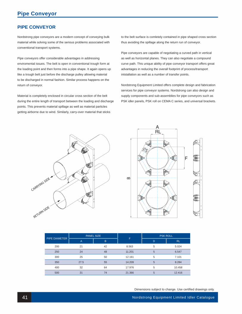
41 Nordstrong Equipment Limited Idler Catalogue
Dimensions subject to change. Use certifi ed drawings only.
Pipe Conveyor
Nordstrong pipe conveyors are a modern concept of conveying bulk
material while solving some of the serious problems associated with
conventional transport systems.
Pipe conveyors offer considerable advantages in addressing
enviromental issues. The belt is open in conventional trough form at
the loading point and then forms into a pipe shape. It again opens up
like a trough belt just before the discharge pulley allowing material
to be discharged in normal fashion. Similar process happens on the
return of conveyor.
Material is completely enclosed in circular cross section of the belt
during the entire length of transport between the loading and discharge
points. This prevents material spillage as well as material particles
getting airborne due to wind. Similarly, carry-over material that sticks
to the belt surface is comletely contained in pipe shaped cross section
thus avoiding the spillage along the return run of conveyor.
Pipe conveyors are capable of negotiating a curved path in vertical
as well as horizontal planes. They can also negotiate a compound
curve path. This unique ability of pipe conveyor transport offers great
advantages in reducing the overall footprint of process/transport
intstallation as well as a number of transfer points.
Nordstrong Equipment Limited offers complete design and fabrication
services for pipe conveyor systems. Nordstrong can also design and
supply components and sub-assemblies for pipe conveyors such as
PSK idler panels, PSK roll on CEMA C series, and universal brackets.
PIPE CONVEYOR
PIPE DIAMETER PANEL SIZE
FPSK ROLL
A B D RL
200 21 42 8.563 5 5.024
250 24 48 11.201 5 6.547
300 25 50 12.161 5 7.101
350 27.5 55 14.209 5 8.284
400 32 64 17.976 5 10.458
500 31 74 21.366 5 12.416
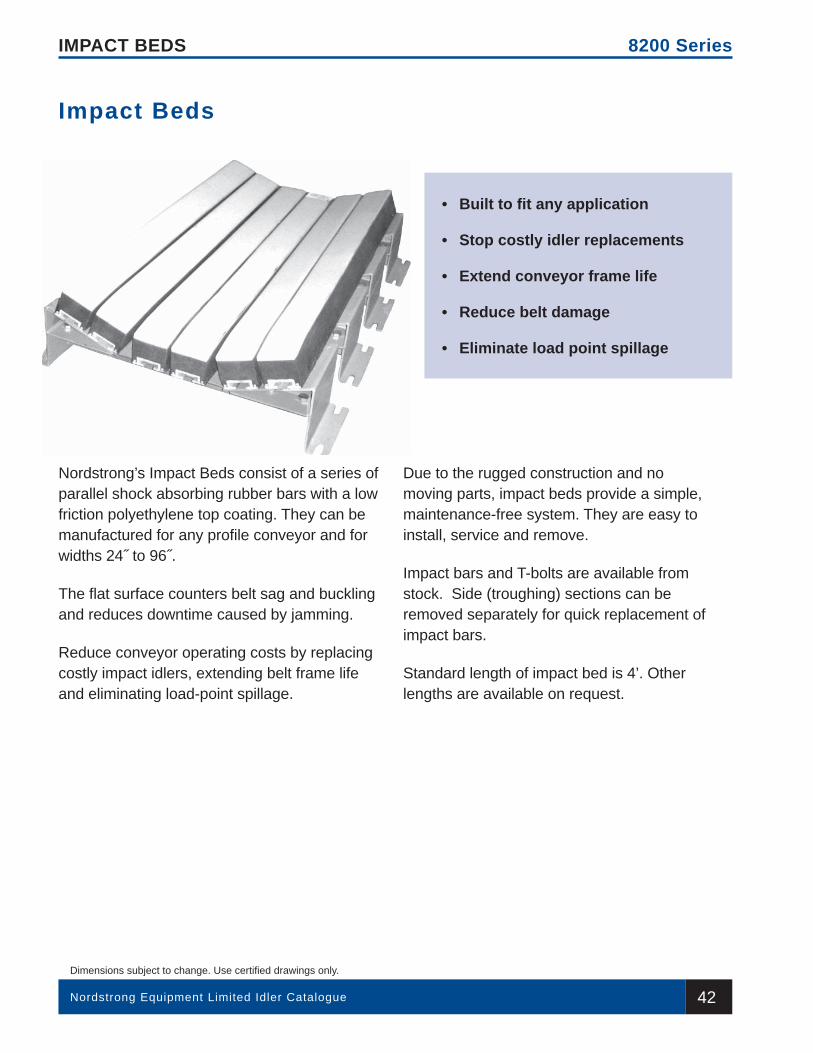
42Nordstrong Equipment Limited Idler Catalogue
Dimensions subject to change. Use certifi ed drawings only.
IMPACT BEDS 8200 Series
Nordstrong’s Impact Beds consist of a series of parallel shock absorbing rubber bars with a low friction polyethylene top coating. They can be manufactured for any profi le conveyor and for widths 24˝ to 96˝.
The fl at surface counters belt sag and buckling and reduces downtime caused by jamming.
Reduce conveyor operating costs by replacing costly impact idlers, extending belt frame life and eliminating load-point spillage.
Due to the rugged construction and no moving parts, impact beds provide a simple, maintenance-free system. They are easy to install, service and remove.
Impact bars and T-bolts are available from stock. Side (troughing) sections can be removed separately for quick replacement of impact bars.
Standard length of impact bed is 4’. Other lengths are available on request.
Impact Beds
• Built to fi t any application
• Stop costly idler replacements
• Extend conveyor frame life
• Reduce belt damage
• Eliminate load point spillage
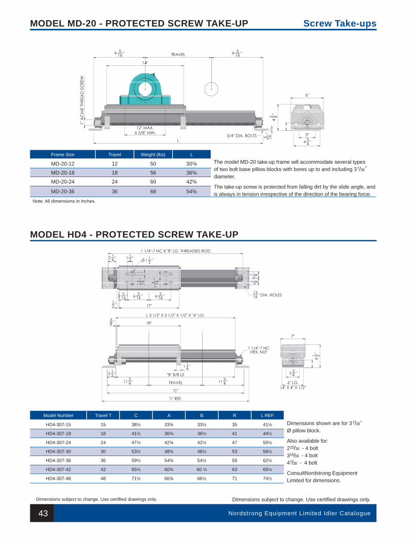
43
IMPACT BEDS
Nordstrong Equipment Limited Idler Catalogue
Dimensions subject to change. Use certifi ed drawings only.
8200 Series
Dimensions subject to change. Use certifi ed drawings only.
MODEL MD-20 - PROTECTED SCREW TAKE-UP
MODEL HD4 - PROTECTED SCREW TAKE-UP
Screw Take-ups
Frame Size Travel Weight (lbs) L
MD-20-12 12 50 305/8 The model MD-20 take-up frame will accommodate several types of two bolt base pillow blocks with bores up to and including 37/16˝ diameter.
The take-up screw is protected from falling dirt by the slide angle, and is always in tension irrespective of the direction of the bearing force.
MD-20-18 18 56 365/8
MD-20-24 24 60 425/8
MD-20-36 36 68 545/8
Note: All dimensions in inches.
Model Number Travel T C A B R L REF
HD4-307-15 15 38½ 33¾ 33½ 35 41½ Dimensions shown are for 37/16˝ Ø pillow block.
Also available for:215/16 - 4 bolt315/16 - 4 bolt47/16 - 4 bolt
ConsultNordstrong Equipment Limited for dimensions.
HD4-307-18 18 41½ 36¾ 36½ 41 44½
HD4-307-24 24 47½ 42¾ 42½ 47 50½
HD4-307-30 30 53½ 48¾ 48½ 53 56½
HD4-307-36 36 59½ 54¾ 54½ 59 62½
HD4-307-42 42 65½ 60¾ 60 ½ 63 65½
HD4-307-48 48 71½ 66¾ 66½ 71 74½
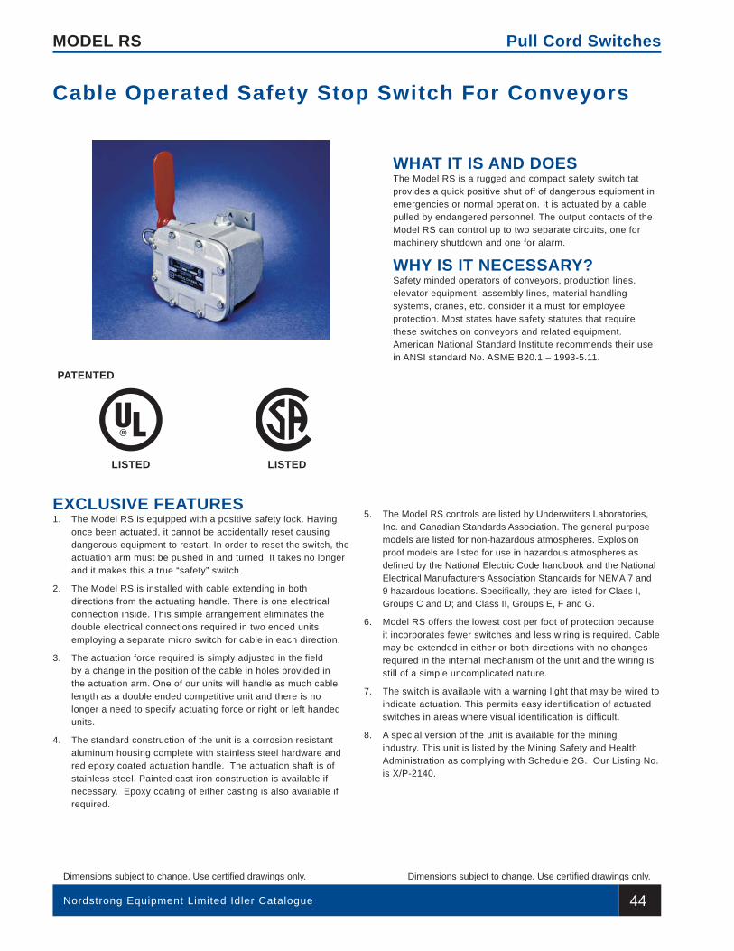
44Nordstrong Equipment Limited Idler Catalogue
Dimensions subject to change. Use certifi ed drawings only.
MODEL RS
Dimensions subject to change. Use certifi ed drawings only.
Pull Cord Switches
WHAT IT IS AND DOESThe Model RS is a rugged and compact safety switch tat provides a quick positive shut off of dangerous equipment in emergencies or normal operation. It is actuated by a cable pulled by endangered personnel. The output contacts of the Model RS can control up to two separate circuits, one for machinery shutdown and one for alarm.
WHY IS IT NECESSARY?Safety minded operators of conveyors, production lines, elevator equipment, assembly lines, material handling systems, cranes, etc. consider it a must for employee protection. Most states have safety statutes that require these switches on conveyors and related equipment. American National Standard Institute recommends their use in ANSI standard No. ASME B20.1 – 1993-5.11.
EXCLUSIVE FEATURES1. The Model RS is equipped with a positive safety lock. Having
once been actuated, it cannot be accidentally reset causing dangerous equipment to restart. In order to reset the switch, the actuation arm must be pushed in and turned. It takes no longer and it makes this a true “safety” switch.
2. The Model RS is installed with cable extending in both directions from the actuating handle. There is one electrical connection inside. This simple arrangement eliminates the double electrical connections required in two ended units employing a separate micro switch for cable in each direction.
3. The actuation force required is simply adjusted in the field by a change in the position of the cable in holes provided in the actuation arm. One of our units will handle as much cable length as a double ended competitive unit and there is no longer a need to specify actuating force or right or left handed units.
4. The standard construction of the unit is a corrosion resistant aluminum housing complete with stainless steel hardware and red epoxy coated actuation handle. The actuation shaft is of stainless steel. Painted cast iron construction is available if necessary. Epoxy coating of either casting is also available if required.
5. The Model RS controls are listed by Underwriters Laboratories, Inc. and Canadian Standards Association. The general purpose models are listed for non-hazardous atmospheres. Explosion proof models are listed for use in hazardous atmospheres as defi ned by the National Electric Code handbook and the National Electrical Manufacturers Association Standards for NEMA 7 and 9 hazardous locations. Specifi cally, they are listed for Class I, Groups C and D; and Class II, Groups E, F and G.
6. Model RS offers the lowest cost per foot of protection because it incorporates fewer switches and less wiring is required. Cable may be extended in either or both directions with no changes required in the internal mechanism of the unit and the wiring is still of a simple uncomplicated nature.
7. The switch is available with a warning light that may be wired to indicate actuation. This permits easy identification of actuated switches in areas where visual identification is difficult.
8. A special version of the unit is available for the mining industry. This unit is listed by the Mining Safety and Health Administration as complying with Schedule 2G. Our Listing No. is X/P-2140.
Cable Operated Safety Stop Switch For Conveyors
PATENTED
LISTED LISTED
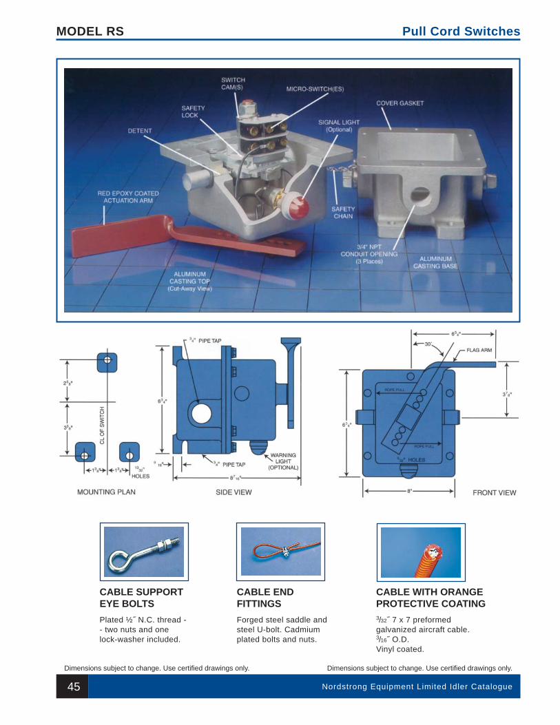
45 Nordstrong Equipment Limited Idler Catalogue
Dimensions subject to change. Use certifi ed drawings only.
MODEL RS
Dimensions subject to change. Use certifi ed drawings only.
Pull Cord Switches
CABLE SUPPORTEYE BOLTS
CABLE ENDFITTINGS
CABLE WITH ORANGEPROTECTIVE COATING
Plated ½˝ N.C. thread -- two nuts and onelock-washer included.
Forged steel saddle andsteel U-bolt. Cadmiumplated bolts and nuts.
3/32˝ 7 x 7 preformedgalvanized aircraft cable.3/16˝ O.D.Vinyl coated.
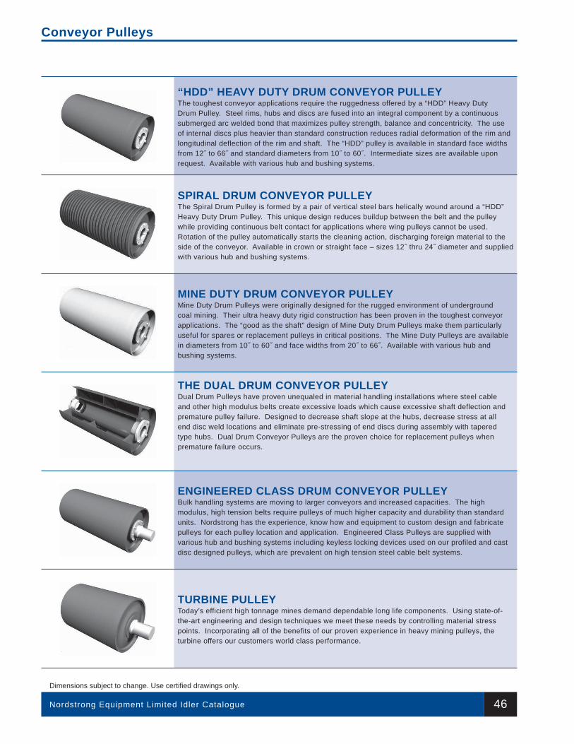
Nordstrong Equipment Limited Idler Catalogue
Dimensions subject to change. Use certifi ed drawings only.
Conveyor Pulleys
“HDD” HEAVY DUTY DRUM CONVEYOR PULLEYThe toughest conveyor applications require the ruggedness offered by a “HDD” Heavy Duty Drum Pulley. Steel rims, hubs and discs are fused into an integral component by a continuous submerged arc welded bond that maximizes pulley strength, balance and concentricity. The use of internal discs plus heavier than standard construction reduces radial deformation of the rim and longitudinal deflection of the rim and shaft. The “HDD” pulley is available in standard face widths from 12˝ to 66˝ and standard diameters from 10˝ to 60˝. Intermediate sizes are available upon request. Available with various hub and bushing systems.
SPIRAL DRUM CONVEYOR PULLEYThe Spiral Drum Pulley is formed by a pair of vertical steel bars helically wound around a “HDD” Heavy Duty Drum Pulley. This unique design reduces buildup between the belt and the pulley while providing continuous belt contact for applications where wing pulleys cannot be used. Rotation of the pulley automatically starts the cleaning action, discharging foreign material to the side of the conveyor. Available in crown or straight face – sizes 12˝ thru 24˝ diameter and supplied with various hub and bushing systems.
MINE DUTY DRUM CONVEYOR PULLEYMine Duty Drum Pulleys were originally designed for the rugged environment of underground coal mining. Their ultra heavy duty rigid construction has been proven in the toughest conveyor applications. The “good as the shaft” design of Mine Duty Drum Pulleys make them particularly useful for spares or replacement pulleys in critical positions. The Mine Duty Pulleys are available in diameters from 10˝ to 60˝ and face widths from 20˝ to 66˝. Available with various hub and bushing systems.
THE DUAL DRUM CONVEYOR PULLEYDual Drum Pulleys have proven unequaled in material handling installations where steel cable and other high modulus belts create excessive loads which cause excessive shaft deflection and premature pulley failure. Designed to decrease shaft slope at the hubs, decrease stress at all end disc weld locations and eliminate pre-stressing of end discs during assembly with tapered type hubs. Dual Drum Conveyor Pulleys are the proven choice for replacement pulleys when premature failure occurs.
ENGINEERED CLASS DRUM CONVEYOR PULLEYBulk handling systems are moving to larger conveyors and increased capacities. The high modulus, high tension belts require pulleys of much higher capacity and durability than standard units. Nordstrong has the experience, know how and equipment to custom design and fabricate pulleys for each pulley location and application. Engineered Class Pulleys are supplied with various hub and bushing systems including keyless locking devices used on our profiled and cast disc designed pulleys, which are prevalent on high tension steel cable belt systems.
TURBINE PULLEYToday’s efficient high tonnage mines demand dependable long life components. Using state-of-the-art engineering and design techniques we meet these needs by controlling material stress points. Incorporating all of the benefits of our proven experience in heavy mining pulleys, the turbine offers our customers world class performance.
46
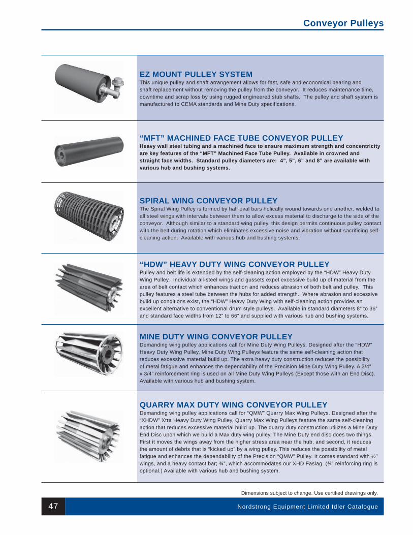
Nordstrong Equipment Limited Idler Catalogue
Dimensions subject to change. Use certifi ed drawings only.
Conveyor Pulleys
EZ MOUNT PULLEY SYSTEMThis unique pulley and shaft arrangement allows for fast, safe and economical bearing and shaft replacement without removing the pulley from the conveyor. It reduces maintenance time, downtime and scrap loss by using rugged engineered stub shafts. The pulley and shaft system is manufactured to CEMA standards and Mine Duty specifications.
“MFT” MACHINED FACE TUBE CONVEYOR PULLEYHeavy wall steel tubing and a machined face to ensure maximum strength and concentricity are key features of the “MFT” Machined Face Tube Pulley. Available in crowned and straight face widths. Standard pulley diameters are: 4”, 5”, 6” and 8” are available with various hub and bushing systems.
SPIRAL WING CONVEYOR PULLEYThe Spiral Wing Pulley is formed by half oval bars helically wound towards one another, welded to all steel wings with intervals between them to allow excess material to discharge to the side of the conveyor. Although similar to a standard wing pulley, this design permits continuous pulley contact with the belt during rotation which eliminates excessive noise and vibration without sacrificing self-cleaning action. Available with various hub and bushing systems.
“HDW” HEAVY DUTY WING CONVEYOR PULLEYPulley and belt life is extended by the self-cleaning action employed by the “HDW” Heavy Duty Wing Pulley. Individual all-steel wings and gussets expel excessive build up of material from the area of belt contact which enhances traction and reduces abrasion of both belt and pulley. This pulley features a steel tube between the hubs for added strength. Where abrasion and excessive build up conditions exist, the “HDW” Heavy Duty Wing with self-cleaning action provides an excellent alternative to conventional drum style pulleys. Available in standard diameters 8” to 36” and standard face widths from 12” to 66” and supplied with various hub and bushing systems.
MINE DUTY WING CONVEYOR PULLEYDemanding wing pulley applications call for Mine Duty Wing Pulleys. Designed after the “HDW” Heavy Duty Wing Pulley, Mine Duty Wing Pulleys feature the same self-cleaning action that reduces excessive material build up. The extra heavy duty construction reduces the possibility of metal fatigue and enhances the dependability of the Precision Mine Duty Wing Pulley. A 3/4” x 3/4” reinforcement ring is used on all Mine Duty Wing Pulleys (Except those with an End Disc). Available with various hub and bushing system.
QUARRY MAX DUTY WING CONVEYOR PULLEYDemanding wing pulley applications call for “QMW” Quarry Max Wing Pulleys. Designed after the “XHDW” Xtra Heavy Duty Wing Pulley, Quarry Max Wing Pulleys feature the same self-cleaning action that reduces excessive material build up. The quarry duty construction utilizes a Mine Duty End Disc upon which we build a Max duty wing pulley. The Mine Duty end disc does two things. First it moves the wings away from the higher stress area near the hub, and second, it reduces the amount of debris that is “kicked up” by a wing pulley. This reduces the possibility of metal fatigue and enhances the dependability of the Precision “QMW” Pulley. It comes standard with ½” wings, and a heavy contact bar; ¾”, which accommodates our XHD Faslag. (¾” reinforcing ring is optional.) Available with various hub and bushing system.
47

Nordstrong Equipment Limited Idler Catalogue
Dimensions subject to change. Use certifi ed drawings only.
Conveyor Pulleys
UNIT HANDLING PULLEYPulleys and rollers used in Unit Handling applications typically have a diameter range of 2” through 8”, although larger diameters are occasionally required.
For moderate loads, 7 through 14 gauge tubing can provide strong construction with economical pricing. For heavier loads 3/16” through 3/8” thick wall tubing is available.
Because manufacturers’ designs vary, we offer a variety of shaft attachment methods as standard options.
PULLEY ASSEMBLIESFor maximum efficiency and added value, we are your single source for conveyor pulley assemblies. We can provide pulley lagging, shafting, bearings and take-up frames to complete the pulley package. Couplings, backstops and other components can also be mounted when required.
SHAFTSConveyor Pulley Shafting is a vital part of the total pulley application. Standard Precision Shafting is AISI 1045, which represents the higher carbon range in the open hearth carbon group. Excluding alloy steel, the higher carbon content in a AISI 1045 results in one of the strongest steels in the carbon range and machines to a smooth finish. Other alloys, including 4140 are available upon request. Shafting can be keyed or journaled to meet any specification.
HUBS AND BUSHINGS*We offer a wide range of hub and bushing systems for proper mounting of pulley to shaft. Included are Q.D. hubs and bushings (maximum bore 12”), X.T. hubs and bushings (maximum bore 12”), Taper-Lock hubs and bushings (maximum bore 12”) and keyless frictional locking assemblies (maximum bore 23.622”). Keyless locking assemblies are self-contained, high torque capacity units that feature no keyway stress concentration, no axial movement during assembly and high torque capacity. Keyless locking assemblies are used primarily with engineered class pulleys in high tension applications. Other means of securing the pulley to the shaft include press-fit and dead shaft designs. We offer you total flexibility when it comes to mounting pulleys to the shaft.
DEFLECTION WHEELSDeflection Wheels are designed for the deflection of corrugated side wall belting. Cross-rigidized base belting with corrugated sidewalls can be deflected from horizontal to any incline and back again with Deflection Wheels. We will build to your specification or our design. Please contact us for size range and availability.
48
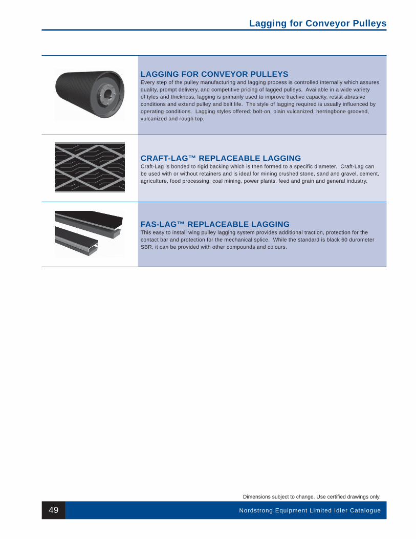
Nordstrong Equipment Limited Idler Catalogue
Dimensions subject to change. Use certifi ed drawings only.
Lagging for Conveyor Pulleys
49
LAGGING FOR CONVEYOR PULLEYSEvery step of the pulley manufacturing and lagging process is controlled internally which assures quality, prompt delivery, and competitive pricing of lagged pulleys. Available in a wide variety of tyles and thickness, lagging is primarily used to improve tractive capacity, resist abrasive conditions and extend pulley and belt life. The style of lagging required is usually influenced by operating conditions. Lagging styles offered: bolt-on, plain vulcanized, herringbone grooved, vulcanized and rough top.
CRAFT-LAG™ REPLACEABLE LAGGINGCraft-Lag is bonded to rigid backing which is then formed to a specific diameter. Craft-Lag can be used with or without retainers and is ideal for mining crushed stone, sand and gravel, cement, agriculture, food processing, coal mining, power plants, feed and grain and general industry.
FAS-LAG™ REPLACEABLE LAGGINGThis easy to install wing pulley lagging system provides additional traction, protection for the contact bar and protection for the mechanical splice. While the standard is black 60 durometer SBR, it can be provided with other compounds and colours.