conveyor equipment manufacturers association · 2018-11-14 · • sprocket types and definition...
TRANSCRIPT

THE VOICE OF THE NORTH AMERICAN CONVEYOR INDUSTRY
AGENDA OF THE CEMA ENGINEERING CONFERENCE
CONVEYOR CHAIN AND SPROCKET COMMITTEE MEETING
Tuesday, June 26, 2018 – 1:00 pm
1. Call to order
2. Meeting Attendance and Introductions
3. Committee Purpose and Value
4. Review and Approval of Previous Minutes (Attached)
5. Old Business
a) Sprocket Types and Definition Document, Draft 1‐Status Review (attached)
6. New Business
a) Discuss including Technical Note: Chordal Action as addendum to Conveyor Chain Installation, Maintenance, & Best Practices – 001 document (attached)
b) New document request: Corrosion Resistant Chains: Coated/Plated vs. Stainless, Plastic chains – when to use. Other – to be specified.
c) CEMA Whitepaper – Volunteers needed (Sample attached)
d) Discuss enhancing Unit Handling Section i. Maintenance guide on chain selection and performance
ii. Definition and detail on how and when to replace chain
7. Next Meeting: June 25, 2019, La Playa Hotel. Naples, FL
8. Adjourn
Tom Perdue, Chair
Roger Bruere, Vice Chair
Conveyor Equipment Manufacturers Association

THE VOICE OF THE CONVEYOR INDUSTRY OF THE AMERICAS
MINUTES OF THE CEMA ANNUAL MEETING CONVEYOR CHAIN AND SPROCKET SECTION MEETING
Naples Grande Beach Resort, Naples, Florida Monday, March 12, 2018
Attendees: Glenn Spungen, PEER Chain Mike Nisenbaum, Timken ‐Carlisle Dean Bogner, Webster Industries Ed Tullar, Groschopp Bob Callahan, Senqcia Maxco Arlo Heynen, Groschopp Dan Fannin, Regal Beloit America Brian Voshell, Cambridge Engineered Solutions Andy Felter, Webster Industries Kevan MacRow, Stephens‐Adamson Jeremy Fogo, PEER Chain Jordan Bloom, Stephens‐Adamson Phil Hannigan, CEMA Mark Duncan, Schneider Electric Kris Ferguson, US Tsubaki Joe Schwegman, Quality Steel Products 1. Meeting was called to order at 7:30 a.m. Minutes from September 2017 were approved. 2. Conveyor Chain Installation, Maintenance & Best Practices‐001, and Technical Report 2018‐01
Conveyor Chain Types & Definitions completed and approved. 3. Conveyor Chain and Sprockets Types & Definitions Draft #1 in process. 4. Future Projects for engineering group
a. Types of corrosion chains i. Coated chains vs stainless chains ii. Plastic chain ‐ when to use
5. Membership & Recruitment a. No new members at this time
6. New Section Chairs a. Chair – Dean Bogner, Webster b. Vice Chair & Secretary – Bob Callahan, Senqcia Maxco
7. New Business a. Changes to ANSI standards will now be reported on as agenda item
i. B29.400 discussed ii. B29.700 discussed iii. Dan Fannin, Regal, will report. In absence he will send report to section chair.
8. White paper discussion – Marketing committee would like sections to submit‐ It will add as future engineering section priority
9. Next Meeting of Section – September 19, 2018 at Hilton Chicago O’Hare Airport, Chicago, IL. 10. Meeting was adjourned at 8:30 a.m. Respectfully Submitted, Dean Bogner, Webster, Chair Bob Callahan, Senqcia Maxco, Vice Chair/Secretary
Conveyor Equipment Manufacturers Association

MINUTES OF CEMA ENGINEERING CONFERENCE CONVEYOR CHAIN & SPROCKET COMMITTEE MEETING
Tuesday, June 27, 2017
1. Call to Order and Roll Call Committee Chair, Tom Perdue, Cambridge Engineered Solutions; called the meeting to order on 1:03 pm
2. Recap of Committee’s Purpose and Value: • Purpose: To provide the most current chain information available within the
industry and represent all types of conveyor chain, i.e. roller, drive, engineered, plastic, wire belt, etc.
• Value: Develop a standardized and effective ability to identify chain products and chain conditions that best fit the needs of member organizations and end user application requirements.
3. Motion to accept 2016 committee meeting minutes – accepted
4. Old business
• Installation, Maintenance, and Best Practices Document – Final Edits and Review. a) Clarify the fact that the chain troubleshooting table is just an example and not
applicable to all types of chain b) Replaced registered trademarked term “Tabletop” with the more generic
term “Slat top” chain • Conveyor Chain Types – Final Edits and Review
a) Clean up opening statement of conveyor chain document to include scope and purpose
5. New Business
• Sprocket Types and Definition Document. The goal is to mimic Chain Types and Definition document:
- Opening statement of sprocket document to include scope and purpose. - Invited members to contribute with sprocket information applicable to each
particular type of chain. Compile a draft by mid-January 2018 Sub-Committee - Topic: Roller Chain – Jeremy Fogo, Peer Chain; Engineered Class Chain – Ray Kisaberth, Webster Industries; Drop Forged Chain – Roger Bruere, 4B Components; Agricultural, Pintle and Detachable Chain – Corey Langner, Timken Drives; Chain Drive Belts – Tom Perdue, Cambridge Engineered Solutions; Plastic Chain Types – Joe Pahlow, Arrowhead Conveyor Corp.
Conveyor Equipment Manufacturers Association

• CEMA request a white paper – Safety. CEMA Marketing Committee has asked for each committee to submit a 1 page white paper regarding an aspect of safety. Will create safety awareness. Topic: List of common potential chain issue indicators to be compiled by Corey Langner, Timken Drives. Document reviewer: Rodney Mishmash, Interroll Corp.
6. Next Meeting: June 26, 2018 at La Playa Hotel, Naples, FL
Attendees
4B Components Ltd. Roger Bruere [email protected]
Arrowhead Conveyor Corporation Joseph Pahlow [email protected]
Bastian Solutions Daniel Hart [email protected] Cambridge Engineered Solutions Thomas Perdue [email protected] INTERROLL Corporation Rodney Mishmash [email protected] Komatsu Mining Corp. Bob Hawkins [email protected] Martin Sprocket & Gear, Inc. David Stronczek [email protected] PEER Chain Jeremy Fogo [email protected] Quality Steel Products Paul Dolan [email protected] Rexnord Industries LLC Raul Morales [email protected] SENQCIA MAXCO, Ltd. Jim Hlinka [email protected] Timken Drives, LLC Corey Langner [email protected] Webster Industries, Inc. Ray Kisaberth [email protected]
Wynright, Daifuku North America Ken Soldan [email protected]
Conveyor Chain and Sprocket Section DRAFT 1‐Conveyor Chain & Belting, Sprocket Types/Def's‐Committee USE ONLY, No distribution w/out CEMA permission. February 5, 2018
Conveyor Chain and Sprockets
Belt Types and Definitions Compilation‐DRAFT 1
Chair: Tom Perdue / Vice‐Chair: Roger Bruere
The CEMA Conveyor Chain & Sprocket Working Group has prepared this document for the
purpose of providing a common level of understanding and terminology of the various types of
sprockets used for conveying chains and belts found throughout the industry today. The scope
of this document includes descriptions and definitions of several sprocket types used for the
following types of chains: roller chains, forged chains, cast chains, welded steel chains,
agricultural chains, steel bushed chains, chain drive belts, and plastic chains. Overall, this
compilation is not intended to be exhaustive, but it does cover most of the types of sprockets
one would find when working with conveyor chains and belts used in the most typical industry
applications.
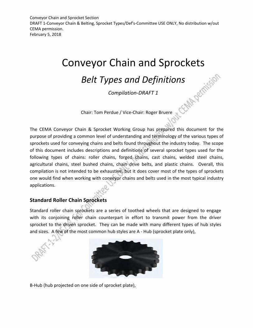
Standard Roller Chain Sprockets
Standard roller chain sprockets are a series of toothed wheels that are designed to engage
with its conjoining roller chain counterpart in effort to transmit power from the driver
sprocket to the driven sprocket. They can be made with many different types of hub styles
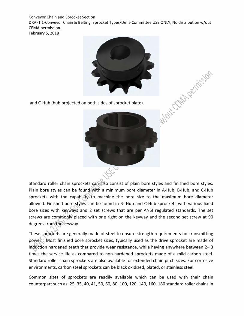
and sizes. A few of the most common hub styles are A ‐ Hub (sprocket plate only),
B‐Hub (hub projected on one side of sprocket plate),
Conveyor Chain and Sprocket Section DRAFT 1‐Conveyor Chain & Belting, Sprocket Types/Def's‐Committee USE ONLY, No distribution w/out CEMA permission. February 5, 2018
and C‐Hub (hub projected on both sides of sprocket plate).
Standard roller chain sprockets can also consist of plain bore styles and finished bore styles.
Plain bore styles can be found with a minimum bore diameter in A‐Hub, B‐Hub, and C‐Hub
sprockets with the capability to machine the bore size to the maximum bore diameter
allowed. Finished bore styles can be found in B‐ Hub and C‐Hub sprockets with various fixed
bore sizes with keyways and 2 set screws that are per ANSI regulated standards. The set
screws are commonly placed with one right on the keyway and the second set screw at 90
degrees from the keyway.
These sprockets are generally made of steel to ensure strength requirements for transmitting
power. Most finished bore sprocket sizes, typically used as the drive sprocket are made of
induction hardened teeth that provide wear resistance, while having anywhere between 2– 3
times the service life as compared to non‐hardened sprockets made of a mild carbon steel.
Standard roller chain sprockets are also available for extended chain pitch sizes. For corrosive
environments, carbon steel sprockets can be black oxidized, plated, or stainless steel.
Common sizes of sprockets are readily available which can be used with their chain
counterpart such as: 25, 35, 40, 41, 50, 60, 80, 100, 120, 140, 160, 180 standard roller chains in
Conveyor Chain and Sprocket Section DRAFT 1‐Conveyor Chain & Belting, Sprocket Types/Def's‐Committee USE ONLY, No distribution w/out CEMA permission. February 5, 2018
A‐, B‐, or C‐Hub styles, or double pitch (extended pitch chains) in A‐ or C‐Hub styles typically
2040/2042, 2050/2052, 2060/2062, and 2080/2082.
Agricultural Chain Sprockets
Sprockets used with agricultural, pintle, or detachable chains are typically made from cast or
wrought ferrous materials. Wear resistance is frequently designed into the material of the
tooth faces. Sprocket bodies are of many configurations. When hubs containing the sprocket
mounting bore are employed, they may project from either side or from both sides of the
sprocket body (B‐ and C‐Hub styles). Since these sprockets are often used in areas where debris
is likely to engage it, root diameters should be decreased and pitch line clearances increased
accordingly. Mud reliefs may be incorporated to prevent root diameter build up. ASME
B29.300 contains specifications relating to these sprockets.
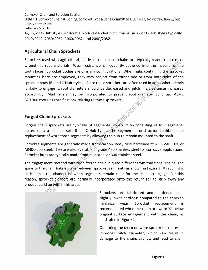
Forged Chain Sprockets
Forged chain sprockets are typically of segmental construction consisting of four segments
bolted onto a solid or split B‐ or C‐Hub types. The segmental construction facilitates the
replacement of worn tooth segments by allowing the hub to remain mounted to the shaft.
Sprocket segments are generally made from carbon steel, case hardened to 450‐550 BHN, or
AR400‐500 steel. They are also available in grade 420 stainless steel for corrosive applications.
Sprocket hubs are typically made from mild steel or 304 stainless steel.
The engagement method with drop forged chain is quite different from traditional chains. The
spine of the chain links engage between sprocket segments as shown in Figure 1. As such, it is
critical that the channel between segments remain clear for the chain to engage. For this
reason, sprocket cleaners are normally incorporated onto the return rail to strip away any
product build up within this area.
Sprockets are fabricated and hardened at a
slightly lower hardness compared to the chain to
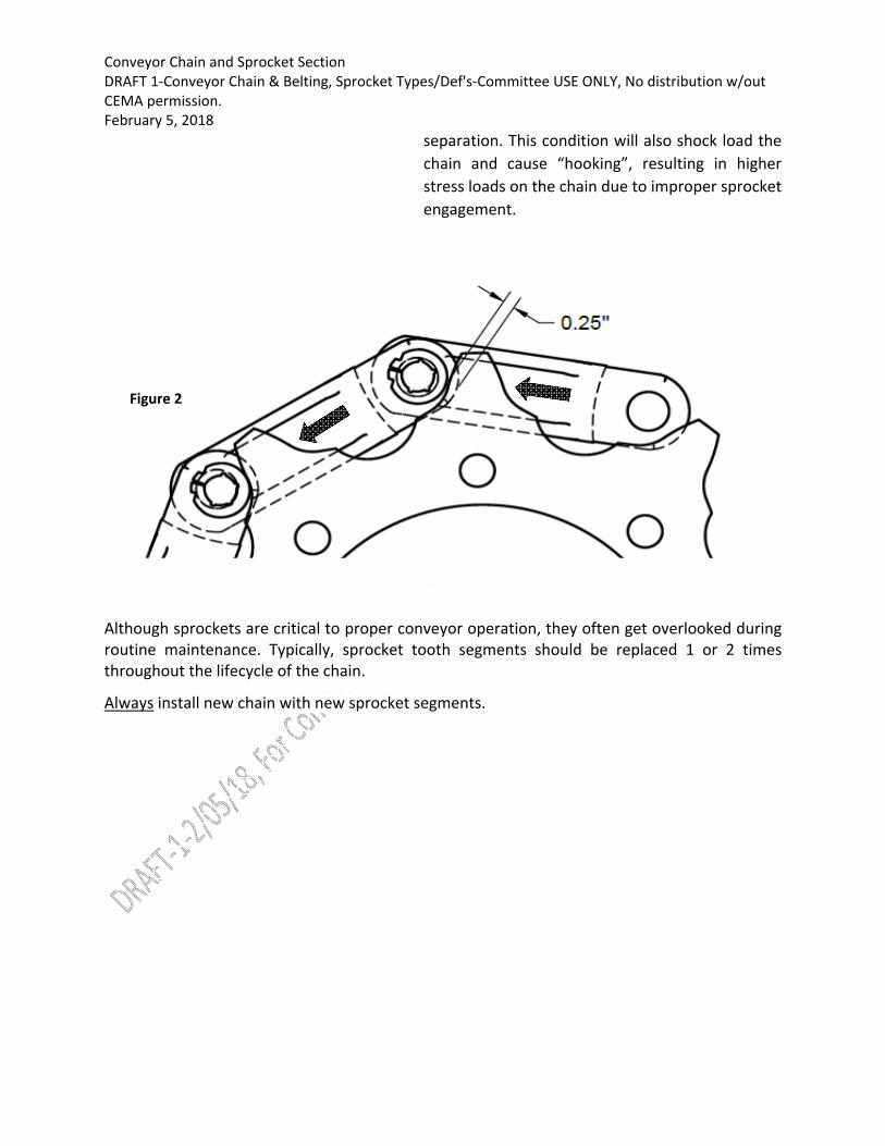
minimize wear. Sprocket replacement is
recommended when the teeth are worn ¼” below
original surface engagement with the chain, as
illustrated in Figure 2.
Operating the chain on worn sprockets creates an
improper pitch diameter, which can result in
damage to the chain, circlips, and lead to chain
Figure 1
Conveyor Chain and Sprocket Section DRAFT 1‐Conveyor Chain & Belting, Sprocket Types/Def's‐Committee USE ONLY, No distribution w/out CEMA permission. February 5, 2018
separation. This condition will also shock load the
chain and cause “hooking”, resulting in higher
stress loads on the chain due to improper sprocket
engagement.
Although sprockets are critical to proper conveyor operation, they often get overlooked during routine maintenance. Typically, sprocket tooth segments should be replaced 1 or 2 times throughout the lifecycle of the chain.
Always install new chain with new sprocket segments.
Figure 2

Conveyor Chain and Sprocket Section DRAFT 1‐Conveyor Chain & Belting, Sprocket Types/Def's‐Committee USE ONLY, No distribution w/out CEMA permission. February 5, 2018
Engineered Class Chain Sprockets
Cast Chain Sprockets
Cast sprockets are generally used with cast chains. They are used in applications that handle
abrasive materials such as sand, gravel, ash or cement.
Cast iron chilled rim (C.I.C.R.) sprockets differentiate themselves because of their hardened
teeth. The hardened teeth are achieved by adding a steel ring or rim in the sprocket pocket of
the mold. The steel then quenches the iron creating a hard surface. The resulting hardness is
approximately 350 BHN at 3/16” depth.
The three types of construction that are available for cast sprockets are solid, split and
segmental. The solid and split construction are furnished with either a solid center plate or a
spoked arm center. Lightening holes are occasionally used in solid center plates to reduce
weight and ease the handling process. The spoked arm sprockets are used on larger sprockets
Conveyor Chain and Sprocket Section DRAFT 1‐Conveyor Chain & Belting, Sprocket Types/Def's‐Committee USE ONLY, No distribution w/out CEMA permission. February 5, 2018
to reduce weight as well. Split and segmental sprockets are used when ease of installation is
required without disturbing the shaft, bearings or other sprockets.
An additional feature of cast sprockets is the opportunity of chain saver rims. They are often
used in sewage treatment applications. The rims are located under the sidebars, and as the
chain wraps the sprocket, they allow for the sidebars to rest on them. The chain saver rims help
the chain to run at the pitch diameter of the sprocket.
Lastly, hunting tooth designs are available on cast sprockets. Hunting tooth sprockets have an
odd number of teeth, with the pitch of the teeth one half that of the chain. This makes the
chain barrel advance one half pitch for each sprocket rotation. This action allows the teeth to
alternate which teeth come in contact with the chain, thereby doubling the sprocket life.
Cast Iron Sprocket with Spoked Arm Center and Chain Saver Rims
Welded Steel Chain Sprockets
Welded Steel Chain is generally categorized as mill or drag chain. These two chains contain
diverse design characteristics and features. Mill chains are typically narrower than drag chains.
Therefore, the sprocket requirements for the two are different.
Mill Chain Sprockets
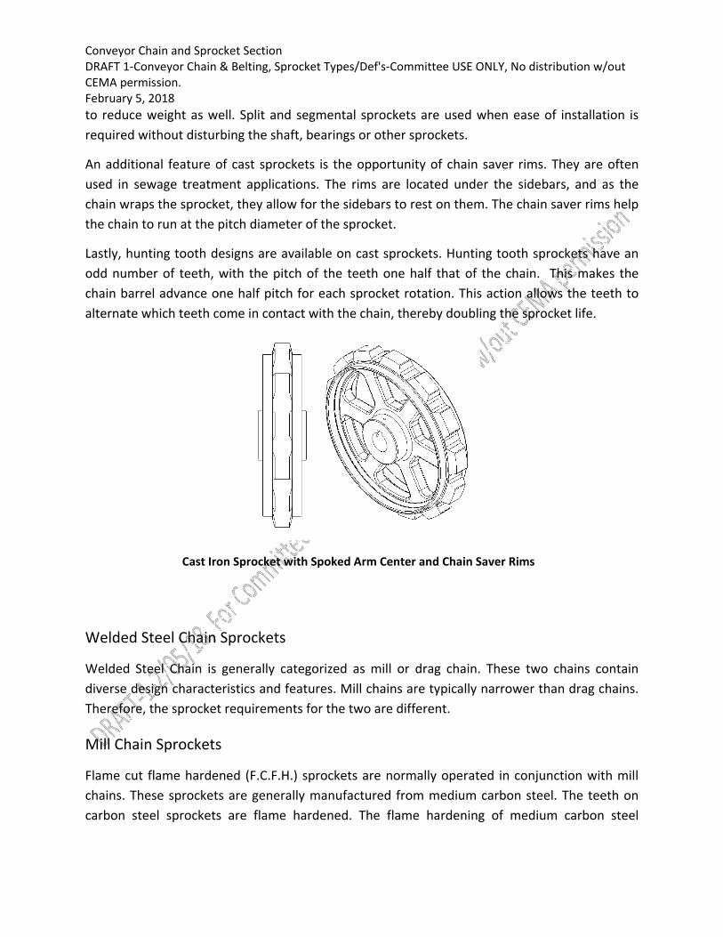
Flame cut flame hardened (F.C.F.H.) sprockets are normally operated in conjunction with mill
chains. These sprockets are generally manufactured from medium carbon steel. The teeth on
carbon steel sprockets are flame hardened. The flame hardening of medium carbon steel

Conveyor Chain and Sprocket Section DRAFT 1‐Conveyor Chain & Belting, Sprocket Types/Def's‐Committee USE ONLY, No distribution w/out CEMA permission. February 5, 2018
results in a hardness of 40 Rc minimum, with an approximate depth of 1/8”. Flame cut flame
hardened sprockets can also be manufactured from alloy steels, as well as stainless.
The two types of construction that are available for mill chain sprockets are solid and split. The
split sprockets are used when ease of installation is required without disturbing the shaft,
bearings or other sprockets. Four basic hub types are available in both solid and split
construction.
Type “A” is a flat plate with no hub extensions on either side.
Type “B” is a flat plate with a hub extension on one side of the plate.
Type “C” is a flat plate with hub extensions that project the same amount on both sides
of the plate.
Type “C Offset” is a flat plate with hub extensions that have different length projections
on both sides of the plate.
Type “A” Type “B” Type “C” Type “C Offset”
An additional feature available on mill chain sprockets are mud reliefs. Mud reliefs are used to
help keep material from building up in the pocket of the sprocket. The relief is normally
machined, burnt or ground in the sprocket plate.
Conveyor Chain and Sprocket Section DRAFT 1‐Conveyor Chain & Belting, Sprocket Types/Def's‐Committee USE ONLY, No distribution w/out CEMA permission. February 5, 2018
Flame Cut Sprocket with Mud Reliefs
Drag Chain Sprockets
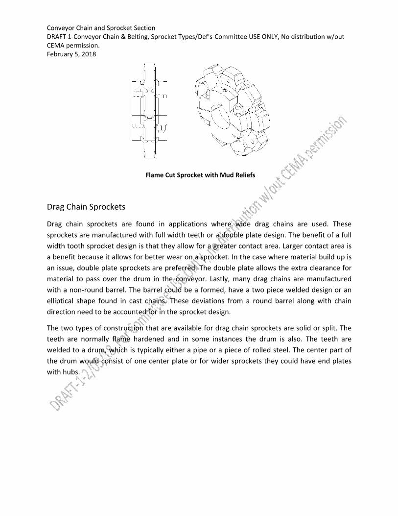
Drag chain sprockets are found in applications where wide drag chains are used. These
sprockets are manufactured with full width teeth or a double plate design. The benefit of a full
width tooth sprocket design is that they allow for a greater contact area. Larger contact area is
a benefit because it allows for better wear on a sprocket. In the case where material build up is
an issue, double plate sprockets are preferred. The double plate allows the extra clearance for
material to pass over the drum in the conveyor. Lastly, many drag chains are manufactured
with a non‐round barrel. The barrel could be a formed, have a two piece welded design or an
elliptical shape found in cast chains. These deviations from a round barrel along with chain
direction need to be accounted for in the sprocket design.
The two types of construction that are available for drag chain sprockets are solid or split. The
teeth are normally flame hardened and in some instances the drum is also. The teeth are
welded to a drum, which is typically either a pipe or a piece of rolled steel. The center part of
the drum would consist of one center plate or for wider sprockets they could have end plates
with hubs.

Conveyor Chain and Sprocket Section DRAFT 1‐Conveyor Chain & Belting, Sprocket Types/Def's‐Committee USE ONLY, No distribution w/out CEMA permission. February 5, 2018
Drag Sprocket with Full Tooth
Drag Sprocket with Double Plate
An additional feature of drag chain sprockets is the option of flanges. Flanges are side
extensions added to the drum that keep material from falling onto the shaft. This sprocket
feature is usually used in conjunction with drag chains that contain wing attachments. It is
imperative that the location of the flange does not interfere with the chain articulation.
Conveyor Chain and Sprocket Section DRAFT 1‐Conveyor Chain & Belting, Sprocket Types/Def's‐Committee USE ONLY, No distribution w/out CEMA permission. February 5, 2018 Drag Sprocket with Full Tooth and Flanged Rim
Elevator Chain Sprockets
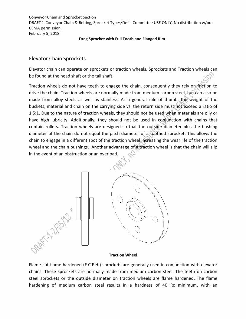
Elevator chain can operate on sprockets or traction wheels. Sprockets and Traction wheels can
be found at the head shaft or the tail shaft.
Traction wheels do not have teeth to engage the chain, consequently they rely on friction to
drive the chain. Traction wheels are normally made from medium carbon steel, but can also be
made from alloy steels as well as stainless. As a general rule of thumb, the weight of the
buckets, material and chain on the carrying side vs. the return side must not exceed a ratio of
1.5:1. Due to the nature of traction wheels, they should not be used when materials are oily or
have high lubricity. Additionally, they should not be used in conjunction with chains that
contain rollers. Traction wheels are designed so that the outside diameter plus the bushing
diameter of the chain do not equal the pitch diameter of a toothed sprocket. This allows the
chain to engage in a different spot of the traction wheel increasing the wear life of the traction
wheel and the chain bushings. Another advantage of a traction wheel is that the chain will slip
in the event of an obstruction or an overload.
Traction Wheel
Flame cut flame hardened (F.C.F.H.) sprockets are generally used in conjunction with elevator
chains. These sprockets are normally made from medium carbon steel. The teeth on carbon
steel sprockets or the outside diameter on traction wheels are flame hardened. The flame
hardening of medium carbon steel results in a hardness of 40 Rc minimum, with an

Conveyor Chain and Sprocket Section DRAFT 1‐Conveyor Chain & Belting, Sprocket Types/Def's‐Committee USE ONLY, No distribution w/out CEMA permission. February 5, 2018
approximate depth of 1/8”. To achieve higher hardness and deeper case depths, sprocket and
traction wheel could be carburized and induction hardened. Flame cut flame hardened
sprockets can also be made from alloy steels, as well as stainless.
The three types of construction that are available for elevator sprockets are solid, split and
segmental. The solid and split construction is furnished with either a solid center plate or a
spoked arm center. Spoked arm sprockets are used on larger sprockets to reduce weight. Split
and segmental sprockets are used when ease of installation is required without disturbing the
shaft, bearings or other sprockets. Lightening holes are sometimes used in solid center plates
for reduced weight as well as for handling.
Solid Construction Split Construction
Conveyor Chain and Sprocket Section DRAFT 1‐Conveyor Chain & Belting, Sprocket Types/Def's‐Committee USE ONLY, No distribution w/out CEMA permission. February 5, 2018 Segmental
Rim Construction
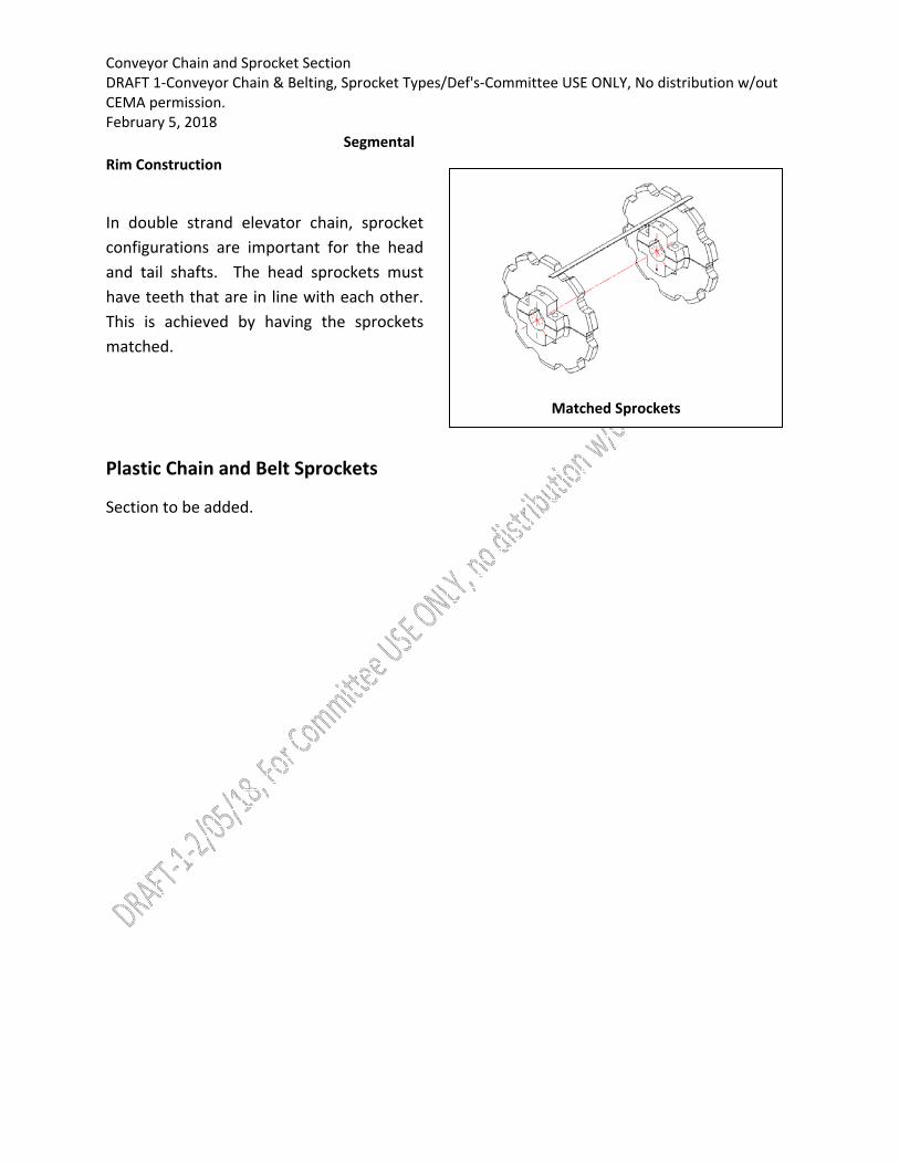
In double strand elevator chain, sprocket
configurations are important for the head
and tail shafts. The head sprockets must
have teeth that are in line with each other.
This is achieved by having the sprockets
matched.
Plastic Chain and Belt Sprockets
Section to be added.
Matched Sprockets

Conveyor Chain and Sprocket Section DRAFT 1‐Conveyor Chain & Belting, Sprocket Types/Def's‐Committee USE ONLY, No distribution w/out CEMA permission. February 5, 2018
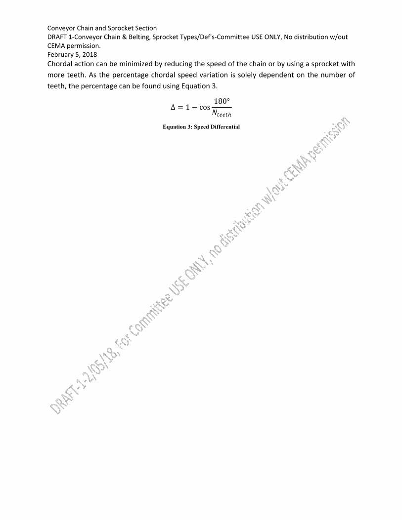
Technical Note: Chordal Action
Chain drives experience a vibration known as chordal action or polygonal effect which occurs as
the effective radius of action in the chain and sprocket system changes during each revolution.
Chordal action can cause increased wear on the chain and sprocket. The effect can be
minimized by using a sprocket with more teeth and virtually eliminated with a sufficiently large
sprocket.
As the sprocket rotates, the engagement position of the chain is restricted by the pitch points
of the links. These pitch points create a polygon, with the number of vertices equal to the
number of sprocket teeth. The resulting polygon defines the maximum and minimum effective
radii illustrated in Figure 3. The radii can be calculated using Error! Reference source not found.
and 2. During rotation, the instantaneous speed of the chain changes, however, the percent
variation will always be constant for a sprocket with a number of teeth N. Figure 4 illustrates
the percentage speed variation versus the number of teeth.
Figure 3: Defining Effective Radii
∗
Equations 1 and 2 Minimum and maximum effective radii
Figure 4: Percentage speed gap for common sprockets
Chordal action can be minimized by reducing th
0.0%
2.0%
4.0%
6.0%
8.0%
10.0%
12.0%
14.0%
16.0%
0 5 10 15 20 25 30 35 40 45 50
Percent Chordal Spee
d Variation
Number of Sprocket Teeth
Speed Differential by Sprocket Size
Conveyor Chain and Sprocket Section DRAFT 1‐Conveyor Chain & Belting, Sprocket Types/Def's‐Committee USE ONLY, No distribution w/out CEMA permission. February 5, 2018
Chordal action can be minimized by reducing the speed of the chain or by using a sprocket with
more teeth. As the percentage chordal speed variation is solely dependent on the number of
teeth, the percentage can be found using Equation 3.
Δ 1 cos180°
Equation 3: Speed Differential
www.cemanet.org
CEMA’sSafetyProgramCONVEYOR SAFETY COMMITTEE
Boyce Bonham, Chief Engineer
Hytrol Conveyor Co., Inc.
Safety ProgramAs a representative and voice for the manufacturers and designers of conveyor equipment worldwide, the Conveyor Equipment Manufacturers Association offers programs and resources for the industry. These include safety guidelines and other means of reducing the risk of injury to operators and maintenance personnel who work with and around our products.
CEMA members do not compete in the area of safety—the guidelines we create are meant to improve the manufacturing and material handling industries across the board. As such, our safety programs are available to anyone in the industry. These are created by the CEMA Safety Committee, a group of engineers from CEMA member companies which meets annually at the CEMA Engineering Conference.
Programs available for use
manufacturing and material handling industry:
ANSI compliant Safety Labels warning against the hazards associated with our products. These are available to both manufacturers and end users of industry equipment and are offered for sale on the CEMA website. These
“DANGER”) to classify the hazard based on the probability of being injured if the hazard is not avoided and the severity of the resulting injury.
Safety label placement guidelines identifying the most effective label placement on bulk and unit handling conveyors. This is available for free on the CEMA website.
Safety Posters that may be downloaded from the site for free. These posters are coordinated with the CEMA safety labels to educate operators on important safety rules that will help prevent injury when working around unit handling conveyors. These signs provide a stand-alone message, but can also be used as a means to recapitulate the messages delivered by the CEMA safety videos and the CEMA safety labels to provide a more holistic safety culture.
Safety Best Practice Guidelines to follow in areas where OSHA and other
• Conveyor Crossovers• E-Stop Application Guide• Supplemental Guarding• Spill Guarding
Tools to assist owners and operators of bulk handling and unit handling conveyors in properly training employees in safety while working with or around conveyor equipment. These tools include safety videos that may be purchased from the CEMA store website. CEMA offers videos to support safety training for users of:
• Unit Handling Conveyors • Screw Conveyors, Drag Conveyors, and Bucket Elevators • Bulk Handling Conveyors
Technical safety information for owners and operators of conveying equipment, including information on:
• Risk Assessment Process • • Noise Considerations
Future Improvements to the Safety ProgramAs with all safety programs, the CEMA safety program relies on continual improvement and suggestions from equipment operators and manufacturers. If you determine that there is a need for additional labels that need to be developed, please bring your concern to the attention of the CEMA Safety Committee by contacting the CEMA Staff at 239.514.3441..
www.cemanet.org

FOR CEMA R
EVIEW OF C
ONV CHAIN
INST, M
AINT AND BP-C
HAIN/SPROCKET C
OMMITTEE- NOT AUTHORIZED FOR D
ISTRIBUTION-06
/04/20
18
Conveyor Chain Installation, Maintenance, & Best Practices - 001
Conveyor Chain - Installation, Maintenance & Best Practices-001
Created by: CEMA Conveyor Chain & Sprocket Section
March, 2018

FOR CEMA R
EVIEW OF C
ONV CHAIN
INST, M
AINT AND BP-C
HAIN/SPROCKET C
OMMITTEE- NOT AUTHORIZED FOR D
ISTRIBUTION-06
/04/20
18
DISCLAIMER
The information provided herein is advisory only.
These recommendations provided by CEMA are general in nature and are not intended as a substitute for professional advice. Users should seek the advice, supervision and/or consultation of qualified engineers, safety consultants, and other qualified professionals.
Any use of this publication, or any information contained herein, or any other CEMA publication is made with the agreement and understanding that the user and the user’s company assume full responsibility for the designs, safety, specifications, suitability and adequacy of any conveyor system, system component, mechanical or electrical device designed or manufactured using this information.
The user and the user’s company understand and agree that CEMA, its member companies, its officers, agents and employees are not and shall not be liable in any manner under any theory of liability to anyone for reliance on or use of these recommendations. The user and the user’s companies agree to release, hold harmless and indemnify and defend CEMA, its member companies, successors, assigns, officers, agents and employees from any and all claims of liability, costs, fees (including attorney’s fees), or damages arising in any way out of the use of this information.
CEMA and its member companies, successors, assigns, officers, agents and employees make no representations or warranties whatsoever, either expressed or implied, about the information contained herein, including, but not limited to, representations or warranties that the information and recommendations contained herein conform to any federal, state or local laws, regulations, guidelines or ordinances.
Conveyor Equipment Manufacturers Association5672 Strand Ct., Suite 2
Naples, Florida 34110-3314www.cemanet.org

FOR CEMA R
EVIEW OF C
ONV CHAIN
INST, M
AINT AND BP-C
HAIN/SPROCKET C
OMMITTEE- NOT AUTHORIZED FOR D
ISTRIBUTION-06
/04/20
18
1 of 17
Conveyor Chain-Installation, Maintenance & Best Practices-001 - March, 2018
Conveyor ChainInstallation, Maintenance, & Best Practices
IntroductionThe careful and correct installation of chains along with a good inspection and maintenance program will typically help improve both the performance and longevity of chains of any type. Obviously, it is better to correct problems found during an inspection than to have to repair the chain after a breakdown; regular inspection and maintenance often costs less than repairs and the associated downtime. Most chains will show signs of trouble long before needing repair or replacement. If problems are found during regular inspections, those problems can possibly be corrected before an unexpected breakdown occurs, thereby reducing the costs associated with component replacement and lost production time. Furthermore, collateral damage caused by a breakdown may not always be found during repairs, leading to additional component failure later and even more unexpected downtime.
To reduce the frequency of untimely breakdowns and the necessary repairs, an inspection program for each chain installation should be established and followed. A checklist of items to inspect should be made and a record of maintenance action kept. Trends can be tracked in that manner and the chain can be adjusted or replaced before a costly failure occurs.
This document has been prepared by the CEMA Conveyor Chain Working Group in an effort to provide a basic level of understanding of the Best Practices associated with the Installation and Maintenance of some of the various types of conveying chains used in industry today. For each type of chain included in this guide, the main emphasis is on operator safety, though this is not intended to be a Safety Manual for the use of these chains. Where applicable, local plant Standard Operating Practices for safety and maintenance should take precedence. But where those defined practices are absent or otherwise insufficient, the practices presented in this document may be helpful and can provide a solid basis for the proper installation and maintenance of the conveyor chains that have been included in this guide.
General Safety PrecautionsSerious personal injury can result if safety rules are not followed. Observe the following safety precautions when inspecting, maintaining, or replacing a chain.
• Shut-off the power to the equipment and lock-out the power switches before inspecting, adjusting, repairing, or replacing chains.
• Always wear safety glasses to protect your eyes.• Wear protective clothing, gloves, and safety shoes as appropriate.• Support the chain to prevent uncontrolled movement of the chain or parts.• Restrain shafts and sprockets from free rotation where such rotation could permit uncontrolled chain
movement and cause personal injury or equipment damage.• Use pressing equipment to remove or install press fit pins or link plates. Keep tooling in good condition
and use it properly. If pressing equipment is not available, contact the chain manufacturer for additional guidance.
• Know and understand chain construction, including the correct direction for pin removal and insertion, before connecting or disconnecting a chain.
General Inspection ProgramAll inspection programs should include the items listed below. These items apply to both drives and conveyors.
• Inspect for signs of interference.• Inspect for chain or sprocket damage.

FOR CEMA R
EVIEW OF C
ONV CHAIN
INST, M
AINT AND BP-C
HAIN/SPROCKET C
OMMITTEE- NOT AUTHORIZED FOR D
ISTRIBUTION-06
/04/20
18
2 of 17
Conveyor Chain-Installation, Maintenance & Best Practices-001 - March, 2018
• Inspect for signs of misalignment of the shafts, sprockets, or ways.• Inspect for dirt or corrosion.• Inspect for proper lubrication.• Inspect for sprocket wear.• Inspect for chain wear.• Inspect for correct chain initial tension.• Inspect for good guarding condition.
This is a list of only the major items that should be inspected regularly. There may be more items that apply to a given application. Any other items should be added to the list.
Many typical chain and sprocket problems are listed and described in general troubleshooting manuals or other pertinent information directly available from CEMA member chain manufacturers. An additional printed resource that can be very helpful is the ACA Standard Handbook of Chains,Chains For Power Transmission and Material Handling - 2nd Edition available for purchase from the Conveyor Equipment Manufacturers Association (CEMA). It is advisable for maintenance personnel to have one or more of these troubleshooting guides on hand when inspecting a chain drive or conveyor. These guides provide not only a list of some of the more common chain problems, but they also provide possible causes and associated remedies.
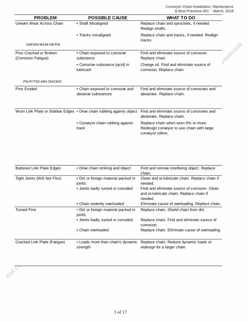
The following Table lists some of the more common types of chain failures along with the associated causes and recommended corrections. It has been included here to provide a good basis and foundation for the basic chain troubleshooting topics discussed below, but is not necessarily applicable to all types of chains. (It should be noted this Table is taken from the aforementioned ACA Standard Handbook of Chains and has been used here with permission.)
PROBLEM POSSIBLE CAUSE WHAT TO DOMissing Parts • Missing at assembly Replace chain.
• Broken and lost Find and correct cause of broken parts. Replace chain.
Missing or Broken Cotters or Spring Clips
• Cotters or spring clip not installed correctly
Install new cotters or spring clip per manufacturer’s instructions
Excessive Noise • Chain striking an object Eliminate interference. Replace Chain.• Loose casing or shaft mounts Tighten fasteners.• Too much chain slack Reset initial chain tension.• Chain badly worn Replace chain. Reset initial chain tension.• Sprockets badly worn Replace sprockets. Realign sprockets.
Replace chain, if not done before.• Sprockets misaligned Replace chain and sprockets, if needed.
Realign sprockets.• Inadequate Lubrication Re-establish proper lubrication. Clean and re-
lubricate chains. Replace chain, if needed.• Chain pitch too large Redesign to use smaller pitch chain.• Too few sprocket teeth Install larger sprockets, if the design permits.
Otherwise, redesign to use larger sprockets.Wear on Inside if Sidebars orRoller Link Plates and on One Side of Sprocket Teeth
• Sprockets misaligned Replace chain and sprockets, if needed. Realign sprockets
FOR CEMA R
EVIEW OF CONV C
HAIN IN
ST, MAIN
T AND BP-CHAIN
/SPROCKET COMMITTEE- N
OT AUTHORIZED FOR DISTRIBUTIO
N-06/04
/2018
3 of 17
Conveyor Chain-Installation, Maintenance & Best Practices-001 - March, 2018
PROBLEM POSSIBLE CAUSE WHAT TO DOUneven Wear Across Chain • Shaft Misaligned Replace chain and sprockets, if needed.
Realign shafts.• Tracks misaligned Replace chain and tracks, if needed. Realign
tracks.
• Chain exposed to corrosivesubstance
Find and eliminate source of corrosion. Replace chain.
• Corrosive substance (acid) inlubricant
Change oil. Find and eliminate source ofcorrosion. Replace chain.
Pins Eroded • Chain exposed to corrosive andabrasive substances
Find and eliminate source of corrosives and abrasives. Replace chain.
Worn Link Plate or Sidebar Edges • Drive chain rubbing against object Find and eliminate source of corrosives and abrasives. Replace chain.
• Conveyor chain rubbing againsttrack
Replace chain when worn 5% or more.Redesign conveyor to use chain with large conveyor rollers.
Battered Link Plate Edges • Drive chain striking and object Find and remove interfering object. Replace chain.
Tight Joints (Will Not Flex) • Dirt or foreign material packed in joints
Clean and re-lubricate chain. Replace chain if needed.
• Joints badly rusted or corroded Find and eliminate source of corrosion. Clean and re-lubricate chain. Replace chain if needed.
• Chain severely overloaded Eliminate cause of overloading. Replace chain.Turned Pins • Dirt or foreign material packed in
jointsReplace chain. Shield chain from dirt.
• Joints badly rusted or corroded Replace chain. Find and eliminate source of corrosion.
• Chain overloaded Replace chain. Eliminate cause of overloading.
Cracked Link Plate (Fatigue) • Loads more than chain's dynamicstrength
Replace chain. Reduce dynamic loads or redesign for a larger chain.
Pins Cracked or Broken (Corrosion Fatigue)
UNEVEN WEAR ON PIN
PIN PITTED AND CRACKED

FOR CEMA R
EVIEW OF C
ONV CHAIN
INST, M
AINT AND BP-C
HAIN/SPROCKET C
OMMITTEE- NOT AUTHORIZED FOR D
ISTRIBUTION-06
/04/20
18
4 of 17
Conveyor Chain-Installation, Maintenance & Best Practices-001 - March, 2018
PROBLEM POSSIBLE CAUSE WHAT TO DOBroken Link Plate • Extreme overload (not suddenly
applied) (often with larger than standard pins)
Replace chain. Reduce loads or redesign for larger chain.
Broken Pin • Extreme overload
Pin Shear • Extreme overload; suddenly applied; shock load. Pin usually shears near inside edge of outer link plate or sidebar
Replace chain. Find and eliminate cause of extreme overload
Pin Break • Extreme overload; not suddenly applied. Pin usually breaks in middle third of length.
Replace chain. Reduce loads or redesign for larger chain.
Pin Fatigue • Loads more than chain's dynamic strength (slightly more than for link plate fatigue). Pin usually fatigues near center of length.
Replace chain. Reduce dynamic loads or redesign for larger chain.
Galled Pins • Speed or load too high Reduce speed or load. Redesign for smaller pitch chain or multiple strand chain.
• Poor Lubrication Correct or improve lubrication system.
Cracked or Broken Rollers • Speed and load more than roller's impact capacity
Replace chain. Reduce speed or redesign for smaller pitch multiple strand chain.
• Too few teeth on sprockets Replace chain. Use sprockets with more teeth or redesign for smaller pitch multiple strand chain.
FOR CEMA R
EVIEW OF C
ONV CHAIN
INST, M
AINT AND BP-C
HAIN/SPROCKET C
OMMITTEE- NOT AUTHORIZED FOR D
ISTRIBUTION-06
/04/20
18
5 of 17
Conveyor Chain-Installation, Maintenance & Best Practices-001 - March, 2018
PROBLEM POSSIBLE CAUSE WHAT TO DORoller Seams Open • Too few teeth on sprockets (as on
a hoist) and loads too highUse sprockets with more teeth. Or replace chain with a high-strength chain having seamless rollers.
• Chain riding too high on sprocket teeth
Reset initial chain tension. Replace chain if worn too much.
Note: Table shows only some of the more common chain problems and possible causes and cures. It is only a generalguide for troubleshooting. The user should always consult the chain manufacturer when a chain fails.
Engineered Class ChainInstallation and Maintenance Guide
Chain Installation:The information below is for guidance only. You MUST always follow the equipment manufacturer’s safety, installation, and maintenance instructions that were provided with the conveyor. Consult your CEMA Conveyor Manufacturer for more details.
Warning: Observe proper lock-out and tag-out procedures when working on or around the conveyor.
The following list of general instructions is provided to assist with the safe and proper installation of Engineered Class Chains:
1. Locations for connecting lengths of chain together should be limited to those links that are intended by the manufacturer for the purpose of repair or replacement. Modifications or repairs to other chain links should be left to or authorized by the chain manufacturer.
2. All conveyor tensioning devices should be adequately loosened before attempting to install the chain on a conveyor.
3. The drive shaft on the conveyor should be locked in place to prevent unintended rotation prior to the attempted chain installation.
4. When possible, connect sections of loose chain together on the floor prior to the installation of the chain on the conveyor.
5. Final connection of the chain to make it endless should preferably be performed at the sprockets. The sprockets can provide adequate support and also help to align the adjoining chain components. This is not always possible, so any location on the conveyor where the chain is adequately supported may suffice.
6. Engineered Class Chains can be large and quite heavy. The following list of tools and equipment is typically recommended for making chain connections. More specialized assembly tools are usually available from the chain manufacturer. Note: it is extremely important that tools and equipment used for chain installation be properly maintained and in good working condition.
a. Hydraulic chain press or hydraulic jackb. Chain vicec. “C” Clampsd. Parallel spacerse. Pliersf. Grinderg. Hacksawh. Hammer
7. When connecting chain sections together, use only new pins or connecting links. Previously used components should be discarded and not re-used.
FOR CEMA REVIEW O
F CONV C
HAININ
ST, MAIN
T AND BP-CHAIN
/SPROCKET COMMITTEE- N
OT AUTHORIZED FOR DISTRIBUTIO
N-06/04
/2018
6 of 17
Conveyor Chain-Installation, Maintenance & Best Practices-001 - March, 2018
8. Avoid damaging chain components during the installation of the chain through excessive heating orgrinding of the chain while attempting to shorten the chain prior to making final connection.
9. For chains that require only a single pin to make a connection:a. Bring the loose ends of the chains together such that the pin holes are aligned.b. Insert the chain connecting pin through the mating links. Align the pin to match the shape of the
pin hole if necessary.c. Support the opposite side of the chain, but allow space for the connecting pin to be fully inserted.d. Press or otherwise drive the chain pin completely through the mating links until it is properly
seated. Support the internal part of the chain link with a spacer if needed.e. Install the cotter pin (if applicable) or rivet the end of the chain pin to form a head. Riveting can be
done by heating the end of the pin until the end is red in color, then peening the pin with a hammer to form the riveted end.
f. Check for free and sufficient articulation of the chain joint. Correct as needed.10. For chains that require a connecting link for assembly:
a. Bring the loose ends of the chains together such that the mating links are aligned but properly spaced (one chain pitch apart) in order to accept the insertion of the connecting link.
b. Insert the chain connecting link through the loose ends of the chains to be connected.c. Place the outer connecting sidebar onto the ends of the connecting link and press it onto the
ends of the pins. Support the opposite side of the pins on the connecting link during this pressing operation. Support the internal part of the chain link with a spacer if needed. Do not press the outer sidebar too far onto the pins as this will make the connecting link too tight and limit the free articulation of the chain joint.
d. Install the cotter pins (if applicable) or rivet the ends of the chain pin to form a head. Riveting can be done by heating the end of the pin until the end is red in color, then peening the pin with a hammer to form the riveted end.
e. Check for free and sufficient articulation of the chain joint. Correct as needed.11. Once the chain has been connected endless on the conveyor, release the lock on the drive shaft if
applicable. Make an initial adjustment to the chain tension to remove excess chain length if needed.12. Slowly start the conveyor; watch the chain and listen to it run. Investigate unusual or suspicious noises
on the conveyor while the chain is running. Also re-adjust the chain tension if necessary. The chain should be tight enough to run smoothly, but no tighter. Over-tensioned chain can result in accelerated chain and sprocket wear.
Chain Maintenance:The information below is for guidance only. You MUST follow the equipment manufacturer’s safety, installation, and maintenance instructions that were provided with the conveyor. Consult your CEMA Conveyor Manufacturer for more details.
Warning: Observe proper lock-out and tag-out procedures when working on or around the conveyor.
The following checklists emphasize key areas for which inspections and maintenance may be needed as it pertains to Engineered Class chains.
Chain or Sprocket Damage: Inspect the chain for any missing, cracked, deformed, corroded, or broken parts. If any are found, search for the cause and correct it. Then replace the entire damaged chain. Even though the rest of the chain may appear to be in good condition, there may be hidden damage.Inspect the sprockets for chipped, broken, or deformed teeth. If any of these problems are found, find the cause and correct it. Then replace the damaged sprocket. Carefully inspect the other sprockets in the drive. If they show any signs of damage, consider replacing them too. When replacing a complete chain, it is a good idea to replace the sprockets also.
Misalignment: Inspect chains for unusual wear on the inside of the sidebars. Inspect all chains for signs of uneven wear of the pins from one side of the chain to the other. Also, inspect the sprockets of chains for unusual wear on one side of the teeth. Correct alignment issues immediately and replace the chain/sprockets as needed.Interference: Check for signs of interference between the chain or sprockets and any other parts of the machine.
FOR CEMA R
EVIEW OF C
ONV CHAIN
INST, M
AINT AND BP-C
HAIN/SPROCKET C
OMMITTEE- NOT AUTHORIZED FOR D
ISTRIBUTION-06
/04/20
18
7 of 17
Conveyor Chain-Installation, Maintenance & Best Practices-001 - March, 2018
One sign of interference is a damaged link or sidebar edges. Other signs of interference include damaged pin ends, bent pins, and broken rollers.Rubbing between the chain or sprockets and other objects can cause unusual wear. Impact between the chain and a solid object can cause the chain to break from fatigue.
Material and Corrosion: Inspect the chain for material packed between sidebars. Also check for tight rollers or tight joints. This could indicate that material is packed between the rollers and bushings or that material is packed between the pin and bushings. Material in these clearance spaces can prevent lubricant from entering critical bearing areas. If found, correct the problem or replace the chain as needed.Inspect the drive for dirt packed between the sprocket teeth and the rollers of roller or engineering steel chains. Dirt in these spaces can stretch the chain or damage rollers.Inspect the chain for cracked link plates or sidebars. Inspect the chain for discolored or pitted parts. These are signs that the chain may have been exposed to a corrosive substance or that the lubricant has been contaminated. If any of these issues are evident on the chain, clean and re-lubricate the chain or replace.
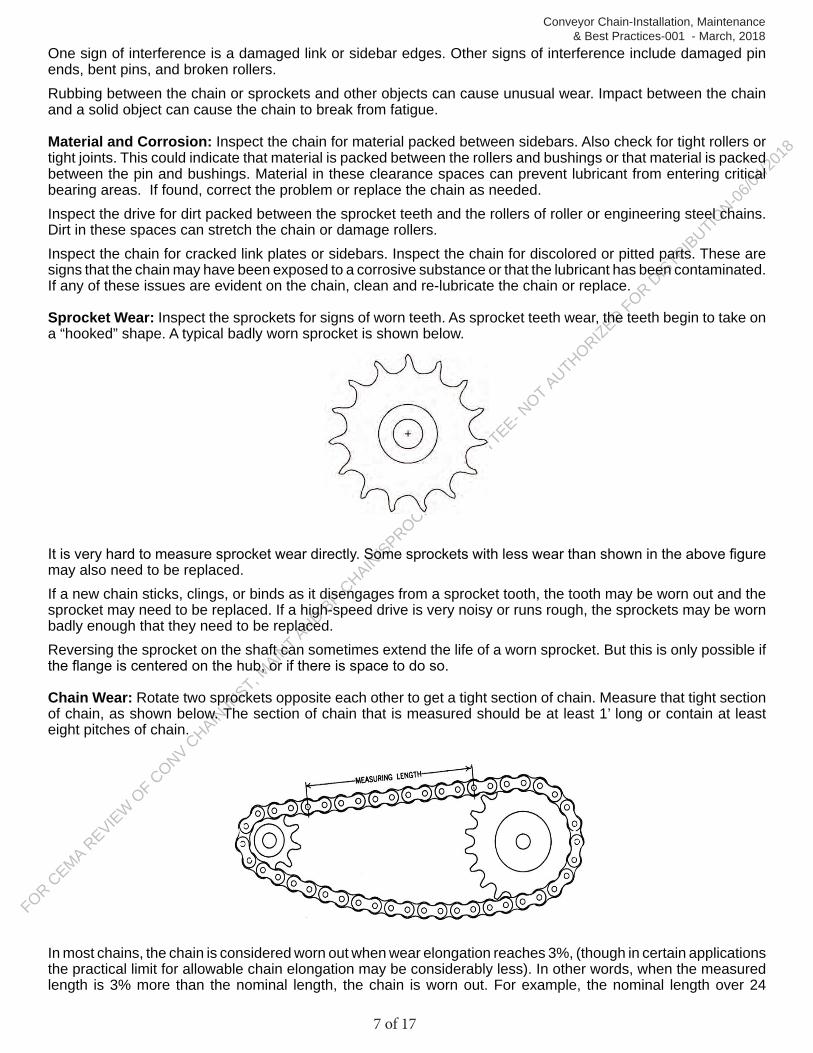
Sprocket Wear: Inspect the sprockets for signs of worn teeth. As sprocket teeth wear, the teeth begin to take on a “hooked” shape. A typical badly worn sprocket is shown below.
It is very hard to measure sprocket wear directly. Some sprockets with less wear than shown in the above figure may also need to be replaced. If a new chain sticks, clings, or binds as it disengages from a sprocket tooth, the tooth may be worn out and the sprocket may need to be replaced. If a high-speed drive is very noisy or runs rough, the sprockets may be worn badly enough that they need to be replaced. Reversing the sprocket on the shaft can sometimes extend the life of a worn sprocket. But this is only possible if the flange is centered on the hub, or if there is space to do so.
Chain Wear: Rotate two sprockets opposite each other to get a tight section of chain. Measure that tight section of chain, as shown below. The section of chain that is measured should be at least 1’ long or contain at least eight pitches of chain.
In most chains, the chain is considered worn out when wear elongation reaches 3%, (though in certain applications the practical limit for allowable chain elongation may be considerably less). In other words, when the measured length is 3% more than the nominal length, the chain is worn out. For example, the nominal length over 24
FOR CEMA R
EVIEW OF C
ONV CHAIN
INST, M
AINT AND BP-C
HAIN/SPROCKET C
OMMITTEE- NOT AUTHORIZED FOR D
ISTRIBUTION-06
/04/20
18
8 of 17
Conveyor Chain-Installation, Maintenance & Best Practices-001 - March, 2018
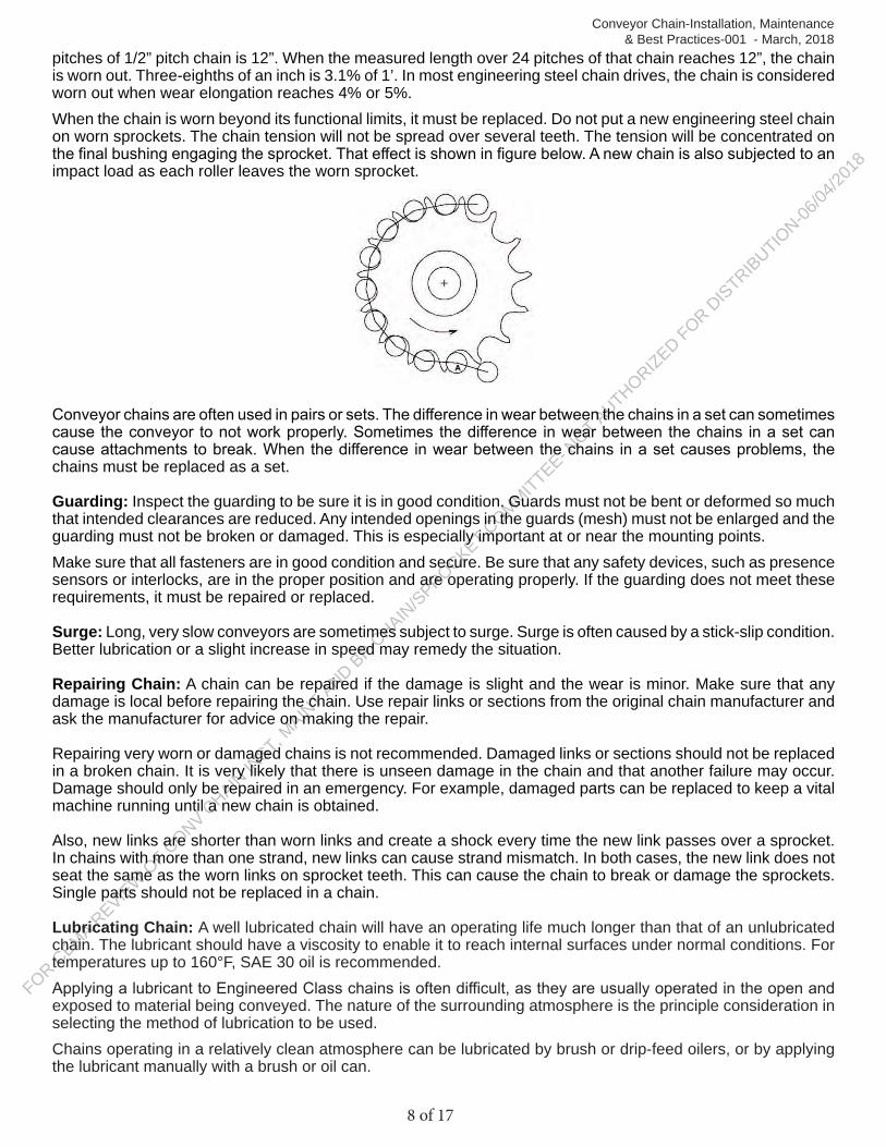
pitches of 1/2” pitch chain is 12”. When the measured length over 24 pitches of that chain reaches 12”, the chain is worn out. Three-eighths of an inch is 3.1% of 1’. In most engineering steel chain drives, the chain is considered worn out when wear elongation reaches 4% or 5%. When the chain is worn beyond its functional limits, it must be replaced. Do not put a new engineering steel chain on worn sprockets. The chain tension will not be spread over several teeth. The tension will be concentrated on the final bushing engaging the sprocket. That effect is shown in figure below. A new chain is also subjected to an impact load as each roller leaves the worn sprocket.
Conveyor chains are often used in pairs or sets. The difference in wear between the chains in a set can sometimes cause the conveyor to not work properly. Sometimes the difference in wear between the chains in a set can cause attachments to break. When the difference in wear between the chains in a set causes problems, the chains must be replaced as a set.
Guarding: Inspect the guarding to be sure it is in good condition. Guards must not be bent or deformed so much that intended clearances are reduced. Any intended openings in the guards (mesh) must not be enlarged and the guarding must not be broken or damaged. This is especially important at or near the mounting points. Make sure that all fasteners are in good condition and secure. Be sure that any safety devices, such as presence sensors or interlocks, are in the proper position and are operating properly. If the guarding does not meet these requirements, it must be repaired or replaced.
Surge: Long, very slow conveyors are sometimes subject to surge. Surge is often caused by a stick-slip condition. Better lubrication or a slight increase in speed may remedy the situation.
Repairing Chain: A chain can be repaired if the damage is slight and the wear is minor. Make sure that any damage is local before repairing the chain. Use repair links or sections from the original chain manufacturer and ask the manufacturer for advice on making the repair.
Repairing very worn or damaged chains is not recommended. Damaged links or sections should not be replaced in a broken chain. It is very likely that there is unseen damage in the chain and that another failure may occur. Damage should only be repaired in an emergency. For example, damaged parts can be replaced to keep a vital machine running until a new chain is obtained.
Also, new links are shorter than worn links and create a shock every time the new link passes over a sprocket. In chains with more than one strand, new links can cause strand mismatch. In both cases, the new link does not seat the same as the worn links on sprocket teeth. This can cause the chain to break or damage the sprockets. Single parts should not be replaced in a chain.
Lubricating Chain: A well lubricated chain will have an operating life much longer than that of an unlubricated chain. The lubricant should have a viscosity to enable it to reach internal surfaces under normal conditions. For temperatures up to 160°F, SAE 30 oil is recommended.Applying a lubricant to Engineered Class chains is often difficult, as they are usually operated in the open and exposed to material being conveyed. The nature of the surrounding atmosphere is the principle consideration in selecting the method of lubrication to be used.Chains operating in a relatively clean atmosphere can be lubricated by brush or drip-feed oilers, or by applying the lubricant manually with a brush or oil can.
FOR CEMA REVIEW O
F CONV C
HAIN IN
ST, MAIN
T AND BP-CHAIN
/SPROCKET COMMITTEE- N
OT AUTHORIZED FOR DISTRIBUTIO
N-06/04
/2018
9 of 17
Conveyor Chain-Installation, Maintenance & Best Practices-001 - March, 2018
Where large volumes of lint or non-abrasive dust are present, a brush or wiper can be used to clean the chain and apply new lubricant. Otherwise, the lint or dust will clog the chain joint clearance and prevent penetration of the oil into the joints.
If abrasives come in contact with the chain, lubrication becomes more difficult. When lubricants are applied externally, abrasive particles tend to adhere to the chain surfaces and act as a lapping or grinding compound. Under extreme conditions it is sometimes advisable to avoid chain lubrication.
Petroleum oils should not be used to lubricate chain operating in temperatures exceeding 300°F. Under certain conditions, chain operating in high temperature atmospheres can be effectively lubricated using finely divided graphite or molybdenum disulfide in a volatile carrier which upon evaporation of the volatile carrier, leaves a thin deposit of solid lubricant on the chain joint surfaces.
Consult a lubricant manufacturer for recommendations when chains are required to operate at elevated temperatures or under other difficult conditions.
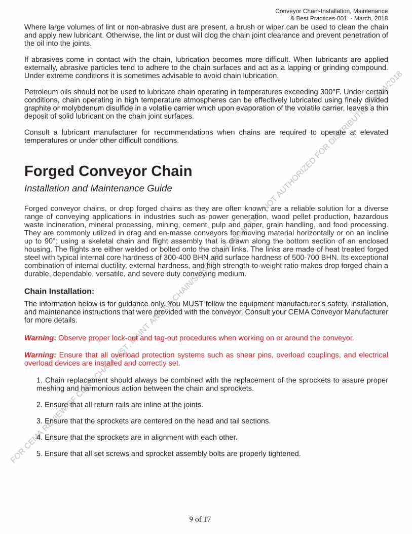
Forged Conveyor ChainInstallation and Maintenance Guide
Forged conveyor chains, or drop forged chains as they are often known, are a reliable solution for a diverse range of conveying applications in industries such as power generation, wood pellet production, hazardous waste incineration, mineral processing, mining, cement, pulp and paper, grain handling, and food processing. They are commonly utilized in drag and en-masse conveyors for moving material horizontally or on an incline up to 90°; using a skeletal chain and flight assembly that is drawn along the bottom section of an enclosed housing. The flights are either welded or bolted onto the chain links. The links are made of heat treated forged steel with typical internal core hardness of 300-400 BHN and surface hardness of 500-700 BHN. Its exceptional combination of internal ductility, external hardness, and high strength-to-weight ratio makes drop forged chain a durable, dependable, versatile, and severe duty conveying medium.
Chain Installation:The information below is for guidance only. You MUST follow the equipment manufacturer’s safety, installation, and maintenance instructions that were provided with the conveyor. Consult your CEMA Conveyor Manufacturer for more details.
Warning: Observe proper lock-out and tag-out procedures when working on or around the conveyor.
Warning: Ensure that all overload protection systems such as shear pins, overload couplings, and electrical overload devices are installed and correctly set.
1. Chain replacement should always be combined with the replacement of the sprockets to assure proper meshing and harmonious action between the chain and sprockets.
2. Ensure that all return rails are inline at the joints.
3. Ensure that the sprockets are centered on the head and tail sections.
4. Ensure that the sprockets are in alignment with each other.
5. Ensure that all set screws and sprocket assembly bolts are properly tightened.
FOR CEMA R
EVIEW OF C
ONV CHAIN
INST, M
AINT AND BP-C
HAIN/SPROCKET C
OMMITTEE- NOT AUTHORIZED FOR D
ISTRIBUTION-06
/04/20
18
10 of 17
Conveyor Chain-Installation, Maintenance & Best Practices-001 - March, 2018
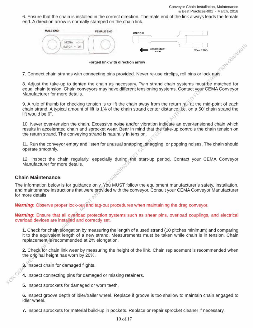
6. Ensure that the chain is installed in the correct direction. The male end of the link always leads the female end. A direction arrow is normally stamped on the chain link.
7. Connect chain strands with connecting pins provided. Never re-use circlips, roll pins or lock nuts.
8. Adjust the take-up to tighten the chain as necessary. Twin strand chain systems must be matched for equal chain tension. Chain conveyors may have different tensioning systems. Contact your CEMA Conveyor Manufacturer for more details.
9. A rule of thumb for checking tension is to lift the chain away from the return rail at the mid-point of each chain strand. A typical amount of lift is 1% of the chain strand center distance; i.e. on a 50’ chain strand the lift would be 6”.
10. Never over-tension the chain. Excessive noise and/or vibration indicate an over-tensioned chain which results in accelerated chain and sprocket wear. Bear in mind that the take-up controls the chain tension on the return strand. The conveying strand is naturally in tension.
11. Run the conveyor empty and listen for unusual snapping, snagging, or popping noises. The chain should operate smoothly.
12. Inspect the chain regularly, especially during the start-up period. Contact your CEMA Conveyor Manufacturer for more details.
Chain Maintenance:The information below is for guidance only. You MUST follow the equipment manufacturer’s safety, installation, and maintenance instructions that were provided with the conveyor. Consult your CEMA Conveyor Manufacturer for more details.
Warning: Observe proper lock-out and tag-out procedures when maintaining the drag conveyor.
Warning: Ensure that all overload protection systems such as shear pins, overload couplings, and electrical overload devices are installed and correctly set.
1. Check for chain elongation by measuring the length of a used strand (10 pitches minimum) and comparing it to the equivalent length of a new strand. Measurements must be taken while chain is in tension. Chain replacement is recommended at 2% elongation.
2. Check for chain link wear by measuring the height of the link. Chain replacement is recommended when the original height has worn by 20%.
3. Inspect chain for damaged flights.
4. Inspect connecting pins for damaged or missing retainers.
5. Inspect sprockets for damaged or worn teeth.
6. Inspect groove depth of idler/trailer wheel. Replace if groove is too shallow to maintain chain engaged to idler wheel.
7. Inspect sprockets for material build-up in pockets. Replace or repair sprocket cleaner if necessary.
Forged link with direction arrow
FOR CEMA R
EVIEW OF C
ONV CHAIN
INST, M
AINT AND BP-C
HAIN/SPROCKET C
OMMITTEE- NOT AUTHORIZED FOR D
ISTRIBUTION-06
/04/20
18
11 of 17
Conveyor Chain-Installation, Maintenance & Best Practices-001 - March, 2018
8. Inspect shaft keys and re-torque hub setscrews and sprocket assembly bolts.
9. Inspect chain rails for damage and wear. 10. Damaged links, pins, retainers and flights MUST be replaced; otherwise it may result in further damage to chain, sprockets and conveyor system.
Chain Drive Wire Mesh BeltInstallation and Maintenance Guide
Chain drive wire mesh belts consist of three major components: wire mesh belt, cross rod supports, and parallel strands of chain. The density of the wire mesh is selected to provide sufficient product support, while the cross rod supports are sized and positioned to provide adequate lateral support to the wire mesh while at the same time connecting the two parallel strands of chain together. This way, the components come together to act as a single conveyor belt unit.
Belt Installation:The information below is for guidance only. You MUST follow the equipment manufacturer’s safety, installation, and maintenance instructions that were provided with the conveyor. Consult your CEMA Conveyor Manufacturer for more details.
Warning: Observe proper lock-out and tag-out procedures when working on or around the conveyor.
Safety: The installation of a wire belt on a unit handling conveyor presents a number of risks for which precautions must be taken. First, it is usually necessary to remove some or all of the conveyor guards during the belt installation process. This exposes the installer to moving components which would normally be shielded. Second, belts of this type are often quite heavy and difficult to handle. Also there may be sharp edges from ends of the wires at the belt edges and/or the old belt to be replaced may have broken or damaged sections with exposed wires that can cut or puncture. As a result, the following minimum safety precautions are strongly advised:
• Wear the proper personal protective equipment.• Practice the proper Lock-out / Tag-out procedures when working on a conveyor belt installation. • Do not attempt to make adjustments to the conveyor or the belt while the conveyor is running or when the belt is moving.• For elevated temperature applications, allow sufficient time for the belt and conveyor to cool prior to making adjustments.
The following general guidelines are suggested for the proper installation of a typical chain drive conveyor belt:1. Pull the belt into the conveyor with a cable or rope. The cable should be attached to a rigid pull bar which
is attached to the belt at the chains only. Secure the leading edge of the woven mesh to the pull bar with wire ties to keep it from becoming damaged during installation, but allow it to remain slightly slack.
2. Pull the belt into the conveyor slowly; apply even tension to both chains, and do not jerk the belt. Be very careful not to allow one strand of chain to take all of the tension.
3. Watch the belt carefully as it comes out of the crate. Remove any kinks from the chain or wire mesh fabric as the belt leaves the crate and before it enters the conveyor.
4. As the belt enters the conveyor, make sure all the spirals on the woven mesh are lying flat. Any spirals that are turned up and creating a hump in the fabric must be turned to lie flat. If these spirals are not turned as the belt is installed, they may become permanently deformed as tension is developed in the belt.
5. Thread the belt completely through the conveyor, top and bottom passes. Join the belt ends together, preferably on a flat surface, where the two ends can be brought together under no tension. Connect the woven mesh first, then connect the chains. The chains will generally connect in one of two ways. Either

FOR CEMA R
EVIEW OF C
ONV CHAIN
INST, M
AINT AND BP-C
HAIN/SPROCKET C
OMMITTEE- NOT AUTHORIZED FOR D
ISTRIBUTION-06
/04/20
18
12 of 17
Conveyor Chain-Installation, Maintenance & Best Practices-001 - March, 2018
a cross rod for the belt will be provided that acts as a chain pin, or a standard chain connector link will be provided. If a cross rod is used, slacken the woven mesh and connect the ends together. Then, insert the cross rod to act as a chain pin and weld the washers provided to each end of the cross rod (depending on the type, some belts will have cottered ends on the cross rods). If a standard chain connector is provided, slacken the fabric and connect the ends together. Then, install the connector link so that the free side plate is on the outside of each strand of chain.
6. Prior to running the belt, inspect all sprockets for proper engagement with the belt. Pay close attention to the drive sprockets to ensure that each strand of chain on the belt is engaged in the same sprocket tooth relative to the chain pitch and/or cross rods. If one strand of chain is installed ahead or behind the other, the belt may be damaged at start-up. All tail and idler shafts should have only one sprocket keyed to the shaft. The other sprocket should be free to float rotationally, but constrained from moving laterally.
7. Whenever possible, chains should be lubricated while in operation. For most room temperature applications, a good grade of light mineral oil should be sufficient. For elevated temperatures, freezing temperatures,and other special processes, a lubricant manufacturer should be consulted for selection of the most effective lubricant.
Belt Maintenance:The information below is for guidance only. You MUST follow the equipment manufacturer’s safety, installation, and maintenance instructions that were provided with the conveyor. Consult your CEMA Conveyor Manufacturer for more details.
Warning: Observe proper lock-out and tag-out procedures when working on or around the conveyor.
As most if not all of the belt tension is carried by the parallel strands of chain, probably the most important maintenance practice to extend the service life of the belt is to keep the chains clean and lubricated. The type of oil selected depends on the operating temperature of the application, but in most non-elevated temperature applications, a suitable grade of mineral oil works best. Some mineral oils specifically intended for chain lubricants also include wear inhibiting additives of which there are also food grade types.
Both the strands of chain and the woven wire mesh will elongate over time and hours of service. Depending on the application and construction of the conveyor, it may be necessary at times to remove small sections of belt. This is normal and to be expected. It is also a good time to check the chain length over a given section on each side of the belt and compare the results. In general, chain lengths from one side of the belt to the other should be the same to within 1/16” across 10’ of belt or more. If this is not the case, then it is likely that the strand of chain that is the longest is also under the most load and/or is getting less lubrication. Remedying this problem sooner rather than later is strongly recommended to preserve the remaining service life of the chain drive belt.
In general, the overall belt can be considered to have reached the end of its useful service life when the strands of chain will no longer match the sprockets. For most chains, this may be at 2.5 - 3% elongation. However, the belt may also be in need of replacement if the wire mesh has been sufficiently damaged or worn. Ideally, one should expect the chains to elongate to the point of creating a severe enough mismatch with the drive sprockets, but the condition of the mesh may be an even more important consideration when deciding to replace the belt.
Following are some specific guidelines for addressing specific problems or issues with chain drive conveyor belts:
1. Chain Binding: A chain drive belt is subjected to all of the typical issues that can go wrong with standard chain, plus the additional complexities caused by the wire mesh itself and the general construction of the overall belt. Because the strands of chain and the mesh and cross rods must function as a single unit, a problem or issue on one side of the belt can cause problems on the opposite side. Chain binding can be the result of an issue with the chain itself, such as lack of sufficient lubrication, or it can result from any or all of the following:
a. Offset in the sprocket engagement between one side of the belt and the other.b. Cross rod ends that extend from the side of the chain and are dragging on the side of the conveyor.c. Drive sprockets that are out of proper position.d. Bent or twisted cross rod(s).
FOR CEMA R
EVIEW OF C
ONV CHAIN
INST, M
AINT AND BP-C
HAIN/SPROCKET C
OMMITTEE- NOT AUTHORIZED FOR D
ISTRIBUTION-06
/04/20
18
13 of 17
Conveyor Chain-Installation, Maintenance & Best Practices-001 - March, 2018
If necessary, the belt should be placed in proper alignment with the sprockets and the conveyor should be checked to make sure it is square. If the welds on some of the cross rods have broken and/or the belt has become twisted or distorted, the belt may need to be replaced unless the damage is limited to a small portion of the overall belt. If the damage is limited, then possibly that section can be replaced.
2. Chain Wear: Excessive chain wear can be caused by insufficient lubrication, interference with the conveyor or a guide component, excessive chain tension, or belt/conveyor misalignment. Depending on the type of wear, check for any interference between the chain(s) and the conveyor itself; also watch the belt as it tracks to determine if it has a tendency to shift to one side or the other, which may indicate an alignment issue. Make certain the belt has not been over-tightened (too little belt on the conveyor, excessive counterweight, etc.). The belt should run with minimum tension possible in order to maximize its service life. If the chains seem dry and debris-filled, they may lack sufficient lubrication.
3. Chain Jumping Sprockets: This is generally caused by excessive chain elongation or some misalignment with the sprockets. The chain should be measured (under load) to determine if the elongation has reached a value where it no longer matches the pitch diameter of the sprockets (approximately 2.5 - 3% elongation). If the chain pitch is still acceptable, then check the position and alignment of the sprockets. The sprockets may be too close together or too far apart to match the width of the assembled belt.The belt may also have a tracking issue causing it to move to one side or the other. The conveyor alignment should be checked to make sure the unit is square with the shafts and the shafts are parallel to each other. Check for any interference in the path of the belt which may be forcing it to shift laterally.
4. Woven Mesh Shifting: This is usually related to a belt tracking problem or an issue with the location/orientation of the support(s) under the wire mesh portion of the belt. The contact between the supports and the wire mesh may be causing the mesh to shift to one side or the other. This may be causing an open area on the belt as the mesh is being pulled away from the chain. Check the position of the supports to see if the mesh is getting caught or restricted, also check the orientation. If possible, the supports should be oriented in a long, herringbone pattern which points in the direction of travel. Additionally, check for bent or distorted mesh in the location where the problem is occurring. Lastly, verify proper alignment of the conveyor support bed with the drive shaft.
5. Sprockets Wearing: Typically caused by the same problems that lead to the chain jumping the sprockets. Generally a result of chain/belt misalignment, improperly placed sprockets, conveyor misalignment, or distorted/damaged belt. First check to make certain the correct sprockets have been used. Attempt to re-position the sprockets if side wear is the issue. If this does not ease the problem, examine the conveyor for an alignment issue and/or check the chains for excessive elongation. Replace the belt and/or sprockets as necessary.
6. Slack Mesh: In general, other than on a pocket belt, the mesh should be slightly slack to slightly taut. Excessive slack in the mesh may be the result of an insufficient number of cross rod supports or a belt that was manufactured with too much lead in the mesh. The mesh may also have become excessively worn due to high tension or distorted due to interaction with the conveyor. If the problem is excessive and is causing issues with product support, the belt may require replacement.
7. Chain Strands Uneven: Presuming there was not an issue with the strands of new chain, then it is likely the chains have developed unequal wear and elongation. This is most likely due to uneven tension from one side of the belt to the other or insufficient lubrication of one of the chains. If chain lubrication is acceptable, then the alignment of the conveyor should be checked and corrected. Depending on the severity of the problem, the entire belt may need to be replaced.

FOR CEMA R
EVIEW OF C
ONV CHAIN
INST, M
AINT AND BP-C
HAIN/SPROCKET C
OMMITTEE- NOT AUTHORIZED FOR D
ISTRIBUTION-06
/04/20
18
14 of 17
Conveyor Chain-Installation, Maintenance & Best Practices-001 - March, 2018
Plastic Conveyor ChainInstallation and Maintenance Guide
Plastic chains are molded polymer, interconnecting, hinge-like modules (links) of various sizes and configurations which are connected end to end to form a continuous, flexible conveying element on which, when installed on a conveyor frame, product in unit form may be transported.
Plastic conveyor chains consist of rigid plastic links which are molded from any one of a variety of durable plastics and mechanically connected by means of a steel pin. Links may be designed such that the pinned connection flexes in the longitudinal direction or in both longitudinal and lateral directions, which are commonly referred to as side flexing (also known as multi-flex and double flex chain). A unique hybrid, two-piece chain design consists of a steel base-chain onto which rigid plastic top plates are snapped in place.
Plastic conveyor chain is widely used in various product transport applications in industry from single strand to multi-strand configurations; whether they are straight-running or curved. Its high strength, rigid polymer construction and array of design features provide for relatively simple installation and low maintenance operation.
Chain Installation:The information below is for guidance only. You MUST follow the equipment manufacturer’s safety, installation, and maintenance instructions that were provided with the conveyor. Consult your CEMA Conveyor Manufacturer for more details.
Warning: Observe proper lock-out and tag-out procedures when working on or around the conveyor.
Safety: As with any power equipment or conveyor system, flat top chain conveyors contain inherent hazards that must be safe guarded. Protection around the areas where the chain engages the drive sprockets as well as sprockets and/or idlers at both the infeed and discharge ends is advisable. Interaction of personnel with a moving plastic chain should be avoided. When necessary, however, such interaction should be in accordance with ASME, OSHA and CEMA safety standards.
The installation of a plastic chain on a unit handling conveyor presents a number of risks for which precautions must be taken. Such risks include (but not limited to):
• Removing some or all of the protective guarding from the conveyor during the chain installation process exposes the installer to moving components which would normally be shielded;
• Pinch points on conveyor and chain, sharp edges of damaged and/or broken links and/or attachments, etc.;
• Handling plastic chain that is quite heavy and/or cumbersome;• Handling conveyor components that have recently been operational, including plastic chain belt(s) which
is to be removed, and carry residual effects such as heat, product contamination, damage, etc.Consequently, the following minimum safety precautions are strongly advised:
• Wear appropriate and proper personal protective equipment.• Implement proper Lock-out / Tag-out procedures when working on a conveyor belt installation. • Do not attempt to make adjustments to the conveyor or the belt while the conveyor is running or when the belt is moving.• Employ proper tools and/or enlist an assistant when attempting to manipulate and managing a large plastic chain alone.• For elevated temperature applications, allow sufficient time for the belt and conveyor to cool prior to making adjustments.
The following general guidelines are suggested for the proper installation of a typical plastic chain conveyor belt:1. Pull a short section of the chain through the entire conveyor to detect any obstructions or areas of tight
clearance.
FOR CEMA R
EVIEW OF C
ONV CHAIN
INST, M
AINT AND BP-C
HAIN/SPROCKET C
OMMITTEE- NOT AUTHORIZED FOR D
ISTRIBUTION-06
/04/20
18
15 of 17
Conveyor Chain-Installation, Maintenance & Best Practices-001 - March, 2018
2. Check conveyor for loose components and fasteners; projections including frame components, weldingsplash; and contamination on sliding surfaces i.e., metal chips, paint, etc.
3. Ensure wear strip joints and the supporting elements are even, and that the clearance between chain andchain guides is correct.
4. Establish proper alignment of sprockets and idlers.5. Properly lubricate entire length of chain, as per manufacturer’s guidelines, with lubricant that is appropriate
for operating conditions and environment. Consult lubricant manufacturer for proper lubricant selection for high and low temperature applications.
6. Relieve any kinks from the chain and inspect involved links as the belt leaves the crate and before it enters the conveyor.
7. Thread the chain completely through the conveyor’s top and bottom paths. Join the ends together, preferably where chain is sufficiently supported so to be managed effectively and ends can be brought together under minimal tension.
8. Inspect all sprockets for proper engagement with the chain prior to start-up.9. Where multiple chains are installed on common shafts, all tail and idler shafts should have only one
sprocket keyed to the shaft; remaining sprockets should be free to rotate about the shaft, but constrained from moving laterally.
10. Upon start-up, run the conveyor without product for 30 minutes to an hour listening for peculiar sounds i.e., clicking, knocking, squeaking, and look for signs of unusual operation.
11. Repeat step 10 while conveying product.12. Check catenary sag while belt is in operation to ensure it is within the manufacturer’s recommended
requirements.
Chain Maintenance:The information below is for guidance only. You MUST follow the equipment manufacturer’s safety, installation, and maintenance instructions that were provided with the conveyor. Consult your CEMA Conveyor Manufacturer for more details.
Warning: Observe proper lock-out and tag-out procedures when working on or around the conveyor.
Periodic inspection of the chain, sprocket and conveyor system is required. The conveyor should be inspected while the system is running as well as when it is shut-off. Items to check for are:
Survey the conveyor for excessive or unusual wear patterns on the chain, track, or wear-strip; look for unusual or excessive debris deposits, such as wear debris accumulation on or beneath the conveyor.
Listen for and locate the source of any unusual noises such as squeaking, clicking or knocking. Inspect chain for top surface flatness and unusual and/or excessive wear or grooves.
Examine sprockets for signs of excessive wear and debris deposits. Check that supporting rollers are turning freely. Review joints in guide track and/or wear strip to ensure there are no irregular offsets either vertically or
horizontally.Look for excessive gaps between links commonly resulting from overload during operation. Periodically measure the chain length for inordinate elongation and check height of chain catenary. Observe the operation of the chain to detect pulsation or jerky motion. Check chain guide track and dead plate clearances to ensure they meet manufacturer’s guidelines. Review the insides of corner wear strips and chain guides and note that excessive heat may indicate
tight clearance or high friction. Ensure that corner turn discs, if used, are properly aligned and turning freely.
FOR CEMA R
EVIEW OF C
ONV CHAIN
INST, M
AINT AND BP-C
HAIN/SPROCKET C
OMMITTEE- NOT AUTHORIZED FOR D
ISTRIBUTION-06
/04/20
18
16 of 17
Conveyor Chain-Installation, Maintenance & Best Practices-001 - March, 2018
Check for excessive heat especially in the curves which may indicate an obstruction, impingement, or high friction area.
Verify that lubrication system is working correctly.
General Maintenance Guidelines
One of the most important maintenance practices to extend the service life of the plastic chain is to keep it clean; free of the accumulation of debris. For the most part, plastic chain operates without the need for supplemental or externally applied lubrication. Guide track and wear strip materials are commonly available with intrinsic lubrication such as oil infused Nylon and other similar materials. Supplemental lubrications can cause the accumulation of debris on the chain and guide materials and accelerate abrasion of the same. When externally applied lubrication is required, such as when running chain in conjunction with metallic guide track or wear strips, consult your plastic chain supplier for recommendations of appropriate lubricants.Plastic will elongate over its time in service. Depending on the application, length of chain, and construction of the conveyor it may be necessary to remove a link or short sections from belt to maintain proper tension and sprocket engagement. Elongation due to wear and thermal expansion is normal and to be expected. In general, the length of a chain in use should not exceed 2-3% of the original length. Greater length differential can lead to engagement failure at the drive sprocket.It is also necessary to check the length of multiple chain strands running in parallel; measuring individual lengths along a particular span of conveyor and compare the results. A difference in length can indicate that the longer strand is being subjected to greater loading. Such added load may be the consequence of chain binding resulting from improper clearances or lack of lubrication. In order to avoid further operational complications, it is advisable to search out the cause and correct the problem as soon as it is detected. Prompt attention to the matter will further serve to preserve the remaining service life of the chain. If an exorbitant difference in chain length exists, it is not advisable to shorten the longer chain to offset the difference; this accomplished by the catenary pocket at the drive.A plastic chain may be considered to have reached the end of its useful service life when it will no longer properly mesh (engage) with the sprocket. This effect occurs, generally, at approximately 2% elongation. It may be necessary, however, to replace the plastic chain if the links have been sufficiently damaged or worn negatively affecting its mesh with the sprocket. Principally, the condition of the mesh will dictate the appropriate time to replace the plastic chain to best serve the operation of the conveyor and service life objectives. It’s important to note that as the chain/sprocket engagement degrades, the stresses of driving the chain resolve to fewer and fewer teeth thereby accelerating sprocket wear and fatigue.The following guidelines present typical measures for addressing specific performance problems with plastic chain conveyor belts:
1. Chain Binding: A plastic chain conveyor belt is subject to many of the typical operating influences and maladies associated with standard chain along with the additional complexities inherent to the unique construction of the plastic chain design. Chain binding can cause erratic operation resulting in problems with throughput and product quality. Following are a number of typical conditions that can cause binding of the chain:
a. Offset in the sprocket engagement between one side of the belt and the other.b. Drive sprockets that are out of proper position.c. Hinge pin(s) protruding from the side of the chain and dragging on guide track.d. Damaged hinge pin(s).e. Improper clearance between chain and guide track, wearstrip, or accessories i.e., dead plates.f. Offset or damaged guide trackg. Insufficient lubrication
Properly align the sprockets (and idlers) with each other – in both the horizontal and vertical planes. Shafts should be adjusted to be parallel and level with each other. Sprocket alignment is also function of proper conveyor frame alignment; consequently, the conveyor should be checked to ensure it is square and level. Prior to chain installation, slide a short section of chain through the conveying path, along the guide track and/or wear strip in order to detect any areas which bind or create inordinate noise and make necessary adjustments or corrections.
FOR CEMA R
EVIEW OF C
ONV CHAIN
INST, M
AINT AND BP-C
HAIN/SPROCKET C
OMMITTEE- NOT AUTHORIZED FOR
DISTRIBUTION-06
/04/20
18
17 of 17
Conveyor Chain-Installation, Maintenance & Best Practices-001 - March, 2018
2. Chain Wear: Excessive chain wear can be caused by interference with the conveyor or a guide component(s), conveyor and/or component misalignment, excessive chain tension, or lack of sufficient lubrication. Depending on the type of wear, check appropriate locations on the conveyor for interference between the chain(s) and the various components. Observing chain movement during operation will enable the observer to pinpoint areas of irregular motion and focus in on specific elements which require maintenance or other attention. Verify that the chain has not been tensioned beyond the recommended limit. Excessive tension could result from insufficient catenary sag, excessive counterweight, chain length being too short, etc. The belt should run through its path with as little tension possible in order to minimize power consumption and maximize its service life. If the chain is debris-filled, check to verify whether lubrication is present (or is recommended).
3. Chain Jumping Sprockets: This is generally caused by misalignment with the sprockets, improper tension, or excessive chain elongation. Check the position and alignment of the sprockets as well as the depth of the catenary. The chain should be measured (under load) to determine if the elongation has reached a value where it no longer matches the pitch diameter of the sprockets (approximately 2-3% elongation). For conveyors with multiple chain strands in parallel, all but one of the sprockets on the tail (idling) shaft must rotate freely about the shaft; the center sprocket alone being keyed. If all sprockets on the tail shaft were keyed, chain and sprocket disengagement will result as the individual strands wear and elongate differently in time. Disengagement of chain and sprocket may also result from component misalignment; commonly causing in miss-tracking. The conveyor alignment should be checked to ensure that the frame is square, the shafts square to the frame, and that they are parallel and level with each other. Check for any interference(s) along the chain paths (conveying and return) that may be forcing it laterally.
4. Sprockets Wearing: Typically brought about by the same influences that lead to chain/sprocket disengagement. Generally, sprocket wear follows as a consequence of conveyor and/or component misalignment, improperly placed sprockets, improper tension, or distorted/damaged chain. First check to make certain the correct sprockets have been used. Should side wear be the problem, examine the conveyor for areas of misalignment and the chains for excessive elongation. If these are found to be within normal limits, reposition the sprockets if possible. Replace the belt and/or sprockets as necessary.
5. Uneven Chain Strand Lengths: Presuming the strands of new chain were properly constructed, it is likely the chains developed unequal wear and elongation over the course of operation. This is commonly due to uneven tension across the various chain strands or insufficient lubrication of one or more chains. If chain lubrication is acceptable, check the alignment of the conveyor and correct as necessary. Depending on the severity of the unevenness, the entire chain set may require replacement.