converting models
TRANSCRIPT

1
PREPARING/CONVERTING STRUCTURAL MODELS
To USFOS
Converting structural models to USFOS 2008-04-01

2
CONTENTS:
1 INTRODUCTION .................................................................................................................................... 3
2 BASIC USFOS MODELLING................................................................................................................ 3 2.1 GENERAL FINITE ELEMENT ................................................................................................................. 3 2.2 LINEAR VS. NON-LINEAR ANALYSIS..................................................................................................... 4
2.2.1 Geometry .................................................................................................................................... 4 2.2.2 Material ...................................................................................................................................... 6 2.2.3 Describing the physical events ................................................................................................... 6
3 SESAM GENIE MODELS ...................................................................................................................... 7 3.1 INTRODUCTION.................................................................................................................................... 7 3.2 WHAT IS TRANSLATED ........................................................................................................................ 7 3.3 UNITS .................................................................................................................................................. 8 3.4 ANALYSIS SETUP ................................................................................................................................ 9 3.5 CONVERTING TO USFOS FORMAT (OPTIONAL)...................................................................................... 9 3.6 RECOMMENDED PROCEDURE............................................................................................................. 10
4 SACS STRUCTURAL FILES............................................................................................................... 12 4.1 INTRODUCTION.................................................................................................................................. 12 4.2 SACS FILE FORMAT BASIC COMMANDS ............................................................................................. 12 4.3 CONVERTING ONE SACS FILES TO USFOS FILE FORMAT .................................................................... 15
4.3.1 Introduction .............................................................................................................................. 15 4.3.2 Alternative 1: Using StruMan................................................................................................... 15 4.3.3 Alternative 2: Using SacRed..................................................................................................... 16 4.3.4 Alternative 3: “Open Model File” from USFOS GUI................................................................ 17 4.3.5 Analysis Setup using the USFOS GUI ...................................................................................... 18
4.4 FOUNDATION DATA ........................................................................................................................... 19 4.5 UNITS ................................................................................................................................................ 19 4.6 HINTS WHEN CREATING THE SACS MODEL FROM SCRATCH.............................................................. 20 4.7 TROUBLESHOOTING........................................................................................................................... 20
5 STAAD STRUCTURAL FILES............................................................................................................ 21 5.1 INTRODUCTION.................................................................................................................................. 21 5.2 STAAD FILE FORMAT BASIC COMMANDS........................................................................................... 21 5.3 CONVERTING ONE STAAD FILES TO USFOS FILE FORMAT................................................................. 24
5.3.1 Introduction .............................................................................................................................. 24 5.3.2 Alternative 1: Using StruMan................................................................................................... 24 5.3.3 Alternative 2: Using StadRed ................................................................................................... 25 5.3.4 Alternative 3: “Open Model File” from USFOS GUI................................................................ 26 5.3.5 Analysis Setup using the USFOS GUI ...................................................................................... 27
5.4 UNITS ................................................................................................................................................ 28 5.5 HINTS WHEN CREATING THE STAAD MODEL FROM SCRATCH .......................................................... 28 5.6 TROUBLESHOOTING........................................................................................................................... 28
6 ABAQUS CAE STRUCTURAL FILES ............................................................................................... 29 6.1 INTRODUCTION.................................................................................................................................. 29
Converting structural models to USFOS 2008-04-01

3
1 Introduction USFOS is a normal finite element code utilizing the same kind of structural information as other similar tools. Converting models to USFOS is therefore relatively straightforward. However, since the models often are created for other purposes than performing non-linear simulations, it is worth spending some time looking into the basics of USFOS.
2 Basic Usfos modelling
2.1 General Finite Element The finite element method means that the physical problem is described by finite elements attached to nodes. Each node has 6 unknowns (the 6 degrees of freedom), and the physical problem is finally represented by an equation system, which has to be solved mathematically by the computer. Model pre-processors are used to create the analysis model, and it is important that the user controls how the finite element model becomes. (A “good-looking” model could very well be a lousy finite element model). In USFOS, the user is free to model “anything”, and it is therefore the user’s responsibility to create a “solvable” equations system. This will be discussed further in section 2.2 below.
6 degrees of freedom,(3 translation and 3 rotations) in each node.
Node
Element
Figure 2-1 General Finite element model in 3D
Converting structural models to USFOS 2008-04-01

4
2.2 Linear vs. non-linear analysis The main differences between linear and non-linear analysis could be expressed with following 4 keywords:
Initial geometry vs updated geometry. Initial material parameters vs updated material. Accepting “non-physics” vs trying to solve the described system. Constant loads/boundary conditions vs. continuously changing b.c./loads.
2.2.1 Geometry While the linear analysis assumes the geometry unchanged by the actual loads, (disregarding the fact that the structure will deform when the equations are solved), the non-linear codes updates the geometry, forms the updated equation system and solves once again, hundreds or thousands of times. Figure 2-2 describes two central components in a 3D frame: the beam and the column. The loads influence the initial shape of the beam and column, and the shape will change. The changed shape will have substantial impact on the components’ stiffness and load carrying capacity.
P
Geometry is updated during the simulation
P Figure 2-2 The geometry is updated every analysis step in USFOS.
Converting structural models to USFOS 2008-04-01

5
Figure 2-3 describes a combined system, the column supporting the beam, (which is axially supported). In the linear analysis, (and in the 1st analysis step of USFOS), the beam carries through beam bending only. The column is straight, and carries with axial compression only. This means that most of the load P is typically carried by the column (the component with highest stiffness, vertically). However, for increasing deformations, the picture will change:
The column becomes softer (bends out, buckles) The beam becomes stiffer (axial tension, membrane effect).
This change in relative stiffness between these two components will change the relative contribution to the total load carrying capacity:
The column becomes less and less important The beam becomes more and more important.
Ultimately, this means that the solution from the linear analysis could be very wrong since the initial shape is used also for full load, (this is one shortcoming with linear analysis).
Initially: Beam Bending
P
Column buckles. (but does not “break”)
Combined bending and axial (membrane)
P Figure 2-3 Updated geometry means load re-distribution
While column buckling is “illegal” in a linear analysis (due to validity), USFOS will continuously update the stiffness and capacity contribution from a gradually buckling column and compute the correct load distribution in the 3D frame. (A column with deformations close to the peak load point has almost unchanged capacity, and ignoring this contribution would be incorrect). USFOS predicts the real behavior of the frame, (“Reality Engineering”).
Converting structural models to USFOS 2008-04-01

6
2.2.2 Material While the end of the elastic range (ε ~0.2%) is the “show stopper” for elastic analysis method (ends the validity), the non-linear analysis is valid also in the plastic range. In the non-linear analysis, the component is contributing to the global frames’ strength up to fracture occurs. It should be emphasized that the deformations (for steel) causing fracture is almost 100 times larger than the deformations causing first yield.
Stress, σ
End of the plastic range, (fracture) for ε ~ 15%
End of the elastic range, (yielding) for ε ~ 0.2%
~1001
Strain, ε
Figure 2-4 Typical stress strain curve for steel
2.2.3 Describing the physical events While a linear, elastic analysis could solve “non-physical” systems models, such systems will typically cause problems in USFOS. For example could a solution giving a stress level of “100,000,000 MPa” be possible for the linear analysis (f ex a dummy member supporting equipment). In USFOS, every component (and equation) has, in principle, same importance/weight. One detail, (like the one described above), could therefore “destroy” the solution, causing singular/near-singular equation systems. USFOS takes all elements “seriously”, and finger-thin pipes or general sections without strength give trouble. Mixing “tiny” details with real (big) structures should therefore be avoided, (skip tiny details). This is of great importance when a model created for linear analysis should be re-used for non-linear analysis in USFOS.
Converting structural models to USFOS 2008-04-01
7
3 SESAM GeniE models
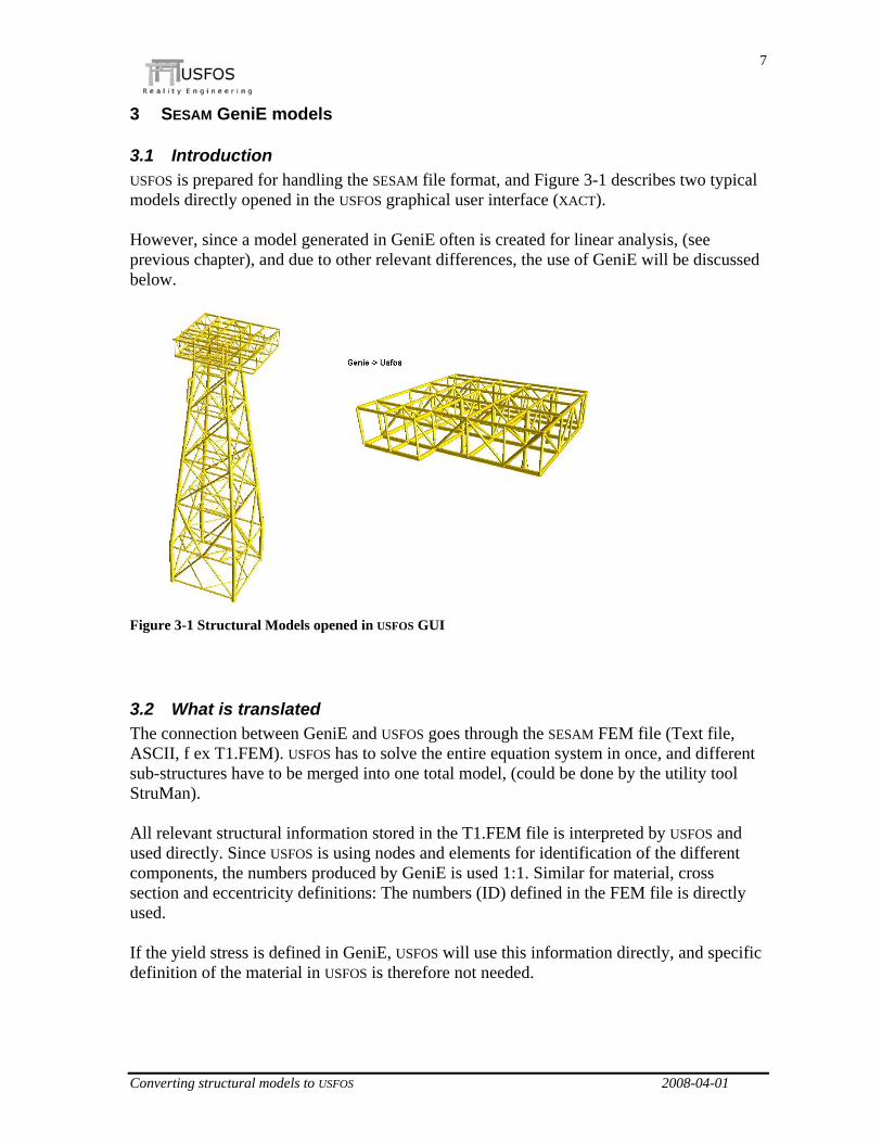
3.1 Introduction USFOS is prepared for handling the SESAM file format, and Figure 3-1 describes two typical models directly opened in the USFOS graphical user interface (XACT). However, since a model generated in GeniE often is created for linear analysis, (see previous chapter), and due to other relevant differences, the use of GeniE will be discussed below. Figure 3-1 Structural Models opened in USFOS GUI
3.2 What is translated The connection between GeniE and USFOS goes through the SESAM FEM file (Text file, ASCII, f ex T1.FEM). USFOS has to solve the entire equation system in once, and different sub-structures have to be merged into one total model, (could be done by the utility tool StruMan). All relevant structural information stored in the T1.FEM file is interpreted by USFOS and used directly. Since USFOS is using nodes and elements for identification of the different components, the numbers produced by GeniE is used 1:1. Similar for material, cross section and eccentricity definitions: The numbers (ID) defined in the FEM file is directly used. If the yield stress is defined in GeniE, USFOS will use this information directly, and specific definition of the material in USFOS is therefore not needed.
Converting structural models to USFOS 2008-04-01

8
All relevant element information, like cross section shape and orientation (local coordinate system), element end offsets (eccentricity), and material properties (stiffness, yield, density and thermal expansion) are taken from the FEM file. Groups of elements (called set in GeniE) are interpreted by USFOS, and could be referred to in connection with specification of USFOS input. Figure 3-2 describes the SESAM sets for a deck frame, (two sets are highlighted).
Figure 3-2 Element groups (SETs) are translated to USFOS
The loads defined in GeniE are translated directly to USFOS, and the load case numbers are used 1:1. Following loads are used by USFOS:
Concentrated (nodal) forces Distributed (beam) loads. Pressure (plate/shell) loads Gravity acceleration
Boundary conditions, (fixed and prescribed displacements), are translated. Concentrated masses (generated on basis on equipment boxes) are translated. Hydrodynamic data are not translated and have to be specified according to USFOS. Foundation data (from gensod) could be utilized through the utility tool soil. The structural model parameters could be verified graphically and in text tables in USFOS gui.
3.3 Units USFOS does not change any unit defined in the FEM file, and the numbers are used directly. it is the user’s responsibility to use consistent units. It is recommended to use pure SI units, (mandatory for USFOS options like hydro, aero, soil).
Converting structural models to USFOS 2008-04-01

9
3.4 Analysis SetUp When a FEM file is opened, most relevant information about the structure is available for verification (f ex cross section dimensions, mass etc). If the user wants to set up the first USFOS control information using the “setup” tool, the loads defined in the FEM file are listed with their load case number and a description of kind of load.
Figure 3-3 Open the model file “T1.FEM” file and the “Analysis Setup” is ready to be used.
3.5 Converting to USFOS format (optional) Although USFOS could use the FEM file directly, (read-only if wanted), it is often convenient to switch to the tailor-made USFOS format, (which is easier to read and modify). This could be done by using StruMan (run from a special Analysis dialogue). It’s just to write the command “UFO” in the control file, save the file and press “run”. The translated model is stored in the file “prefix”_ufo.fem, (which should be opened and looked into).
Converting structural models to USFOS 2008-04-01

10
3.6 Recommended procedure If GeniE is used for model generation to USFOS, following hints could ease the succeeding operation: Modelling
Create the jacket without piles Use as coarse element mesh as possible:
o One beam element per physical member (if possible). For example will the automatic member imperfection give best results for one element, etc.
o Avoid using a fine mesh on deck plating present for in-plane stiffness purpose. Nodes in the meshed deck will have extremely low lateral stiffness (ref equation system. Skip deck plating and insert manually if GeniE cannot handle this).
Create individual material nos for different parts, (material is a convenient way to identify elements in USFOS).
If possible, prepare the ALS dead weight load cases and collect in one load case, (or even better, use masses). The basic loads which have to be applied on the structure prior to the ALS loads are then easy to handle.
Export the FEM file Freeze this model. USFOS refers to element and node numbers, and even the
smallest change in the GeniE model will generate new numbers. (and the USFOS input has to be updated ). Convert to USFOS file format if you need to change the model at a later stage.
Do not include piles in the FE model exported to USFOS! (USFOS creates complete foundation automatically).
Figure 3-4 Export the structure WITHOUT piles
Checking model Apply the know dead weight load case (which is possible to run in GeniE too):
Check reaction vs USFOS results for load level=1.0 Check stress level (or code check)
Same reaction forces and stresses should be obtained.
Converting structural models to USFOS 2008-04-01

11
Hydro dynamic calculations If the built in hydrodynamic module (computing the wave forces) are used, the following have to be done:
Specify the hydrodyn parameters according to USFOS definitions, (latest input syntax is recommended).
Run one step and “Verify hydrodynamics”. Check that correct Cd, Cm, Marine Growth, Shielding, etc are specified.
Run same wave in USFOS and GeniE and compare base shear. Foundation If an integrated analysis (structure + pile/soil) should be performed, following alternatives exist:
Use the built in API soil option in USFOS.
Use the user-defined soil option: o Create the P-Y, T-Z and Q-Z manually o Translate the soil.10 data from gensod using the tool soil.
Specify the piles by the following:
o pile head node and pile tip node (aux node which has to be defined manually)
o Pile geometry and steel properties (ordinary USFOS material) o Soil characteristic used along the pile(s).
Check always the performance of one single pile in compression and tension to
verify the used data. Compare with geotechnical reports.
Converting structural models to USFOS 2008-04-01

12
4 SACS structural files
4.1 Introduction In most cases, the structural model exists from the linear design, and re-use of this model saves time and effort in most cases. However, converting models “100% automatically” seldom is the case. Normally the user has to control the quality of the converted model. Based on experience, some simple precautions will ease the conversion process. Below, the conversion process is described step by step.
4.2 Sacs File Format basic commands
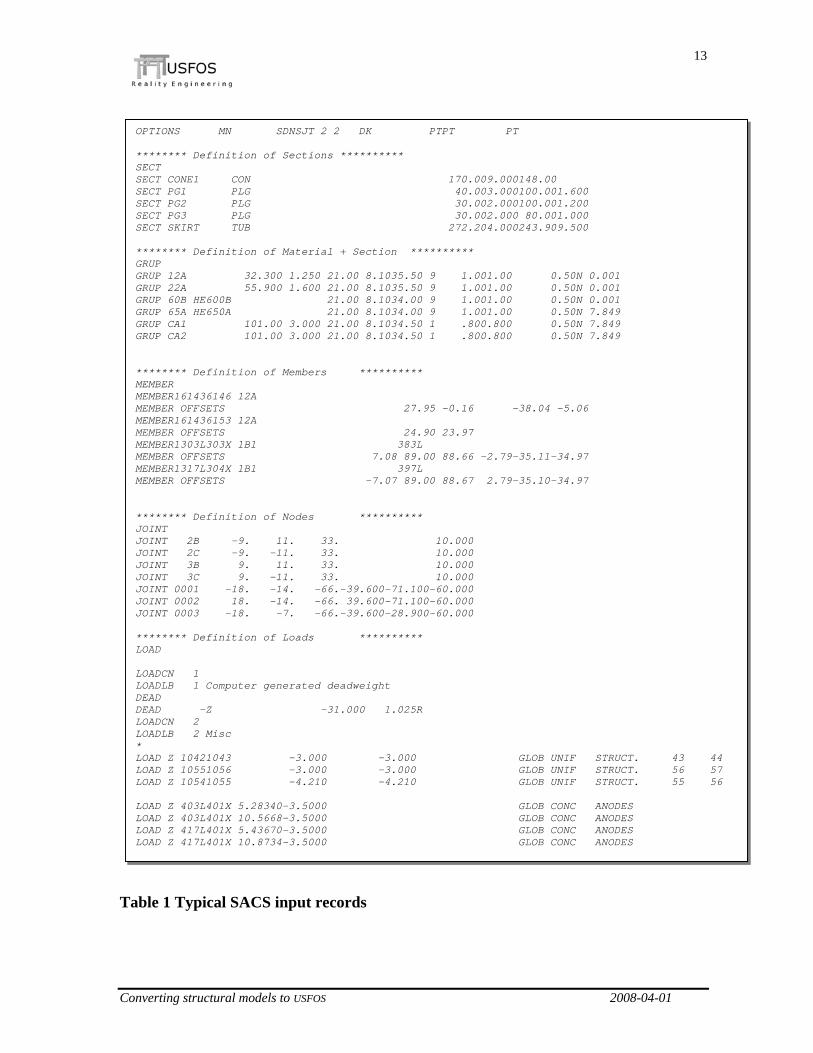
OPTIONS : Defines Units etc SECT : Defines Cross Sections (Standard or Built up) GRUP : Defines combinations of material and sections MEMBER : Defines member between Joints. Refers to GRUP JOINT : Defines Joint Coordinates LOAD : Defines Loads LOADCN : Defines Load Case Number LOADLB : Defines Load Label
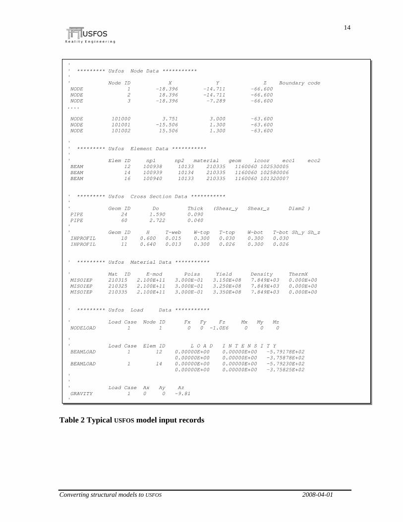
Table 1 gives an example of typical SACS input records, which are decoded by Usfos. Table 2 gives and example of the most important input records according to USFOS structural file format. The SACS input records are translated to the corresponding USFOS record during the automatic conversion, and written to a new file.
Converting structural models to USFOS 2008-04-01
13
T
C
OPTIONS MN SDNSJT 2 2 DK PTPT PT ******** Definition of Sections ********** SECT SECT CONE1 CON 170.009.000148.00 SECT PG1 PLG 40.003.000100.001.600 SECT PG2 PLG 30.002.000100.001.200 SECT PG3 PLG 30.002.000 80.001.000 SECT SKIRT TUB 272.204.000243.909.500 ******** Definition of Material + Section ********** GRUP GRUP 12A 32.300 1.250 21.00 8.1035.50 9 1.001.00 0.50N 0.001 GRUP 22A 55.900 1.600 21.00 8.1035.50 9 1.001.00 0.50N 0.001 GRUP 60B HE600B 21.00 8.1034.00 9 1.001.00 0.50N 0.001 GRUP 65A HE650A 21.00 8.1034.00 9 1.001.00 0.50N 7.849 GRUP CA1 101.00 3.000 21.00 8.1034.50 1 .800.800 0.50N 7.849 GRUP CA2 101.00 3.000 21.00 8.1034.50 1 .800.800 0.50N 7.849 ******** Definition of Members ********** MEMBER MEMBER161436146 12A MEMBER OFFSETS 27.95 -0.16 -38.04 -5.06 MEMBER161436153 12A MEMBER OFFSETS 24.90 23.97 MEMBER1303L303X 1B1 383L MEMBER OFFSETS 7.08 89.00 88.66 -2.79-35.11-34.97 MEMBER1317L304X 1B1 397L MEMBER OFFSETS -7.07 89.00 88.67 2.79-35.10-34.97 ******** Definition of Nodes ********** JOINT JOINT 2B -9. 11. 33. 10.000 JOINT 2C -9. -11. 33. 10.000 JOINT 3B 9. 11. 33. 10.000 JOINT 3C 9. -11. 33. 10.000 JOINT 0001 -18. -14. -66.-39.600-71.100-60.000 JOINT 0002 18. -14. -66. 39.600-71.100-60.000 JOINT 0003 -18. -7. -66.-39.600-28.900-60.000 ******** Definition of Loads ********** LOAD LOADCN 1 LOADLB 1 Computer generated deadweight DEAD DEAD -Z -31.000 1.025R LOADCN 2 LOADLB 2 Misc * LOAD Z 10421043 -3.000 -3.000 GLOB UNIF STRUCT. 43 44 LOAD Z 10551056 -3.000 -3.000 GLOB UNIF STRUCT. 56 57 LOAD Z 10541055 -4.210 -4.210 GLOB UNIF STRUCT. 55 56 LOAD Z 403L401X 5.28340-3.5000 GLOB CONC ANODES LOAD Z 403L401X 10.5668-3.5000 GLOB CONC ANODES LOAD Z 417L401X 5.43670-3.5000 GLOB CONC ANODES LOAD Z 417L401X 10.8734-3.5000 GLOB CONC ANODES
able 1 Typical SACS input records
onverting structural models to USFOS 2008-04-01
14
' ' ********* Usfos Node Data *********** ' ' Node ID X Y Z Boundary code NODE 1 -18.396 -14.711 -66.600 NODE 2 18.396 -14.711 -66.600 NODE 3 -18.396 -7.289 -66.600 .... NODE 101000 3.751 3.000 -63.600 NODE 101001 -15.506 1.300 -63.600 NODE 101002 15.506 1.300 -63.600 ' ' ********* Usfos Element Data *********** ' ' Elem ID np1 np2 material geom lcoor ecc1 ecc2 BEAM 12 100938 10133 210335 1160060 102530005 BEAM 14 100939 10134 210335 1160060 102580006 BEAM 16 100940 10133 210335 1160060 101320007 ' ********* Usfos Cross Section Data *********** ' ' Geom ID Do Thick (Shear_y Shear_z Diam2 ) PIPE 24 1.590 0.090 PIPE 60 2.722 0.040 ' ' Geom ID H T-web W-top T-top W-bot T-bot Sh_y Sh_z IHPROFIL 10 0.600 0.015 0.300 0.030 0.300 0.030 IHPROFIL 11 0.640 0.013 0.300 0.026 0.300 0.026 ' ********* Usfos Material Data *********** ' Mat ID E-mod Poiss Yield Density ThermX MISOIEP 210315 2.100E+11 3.000E-01 3.150E+08 7.849E+03 0.000E+00 MISOIEP 210325 2.100E+11 3.000E-01 3.250E+08 7.849E+03 0.000E+00 MISOIEP 210335 2.100E+11 3.000E-01 3.350E+08 7.849E+03 0.000E+00 ' ********* Usfos Load Data *********** ' Load Case Node ID Fx Fy Fz Mx My Mz NODELOAD 1 1 0 0 -1.0E6 0 0 0 ' ' Load Case Elem ID L O A D I N T E N S I T Y BEAMLOAD 1 12 0.00000E+00 0.00000E+00 -5.79178E+02 0.00000E+00 0.00000E+00 -3.75878E+02 BEAMLOAD 1 14 0.00000E+00 0.00000E+00 -5.79230E+02 0.00000E+00 0.00000E+00 -3.75825E+02 ' ' ' Load Case Ax Ay Az GRAVITY 1 0 0 -9.81 '
Table 2 Typical USFOS model input records
Converting structural models to USFOS 2008-04-01
15
4.3 Converting one SACS files to USFOS file format
4.3.1 Introduction The SACS file could be translated to USFOS format in any of the three ways:
Running StruMan (General file converter) Running SacRed (stand alone SACS translator) “Open Model File” from the USFOS GUI.
4.3.2 Alternative 1: Using StruMan Following has to be done:
Copy (or rename) the SACS input to a file with extension .fem (f.ex sacin.fem) Create a new file (STRUMAN control file) which contains only one command, see
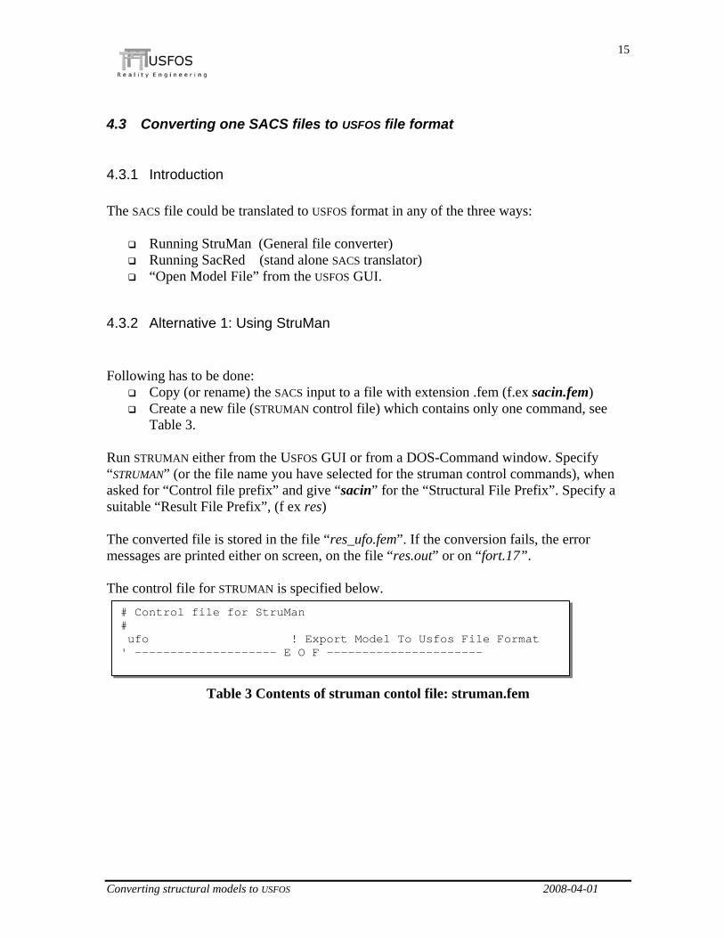
Table 3. Run STRUMAN either from the USFOS GUI or from a DOS-Command window. Specify “STRUMAN” (or the file name you have selected for the struman control commands), when asked for “Control file prefix” and give “sacin” for the “Structural File Prefix”. Specify a suitable “Result File Prefix”, (f ex res) The converted file is stored in the file “res_ufo.fem”. If the conversion fails, the error messages are printed either on screen, on the file “res.out” or on “fort.17”. The control file for STRUMAN is specified below.
C
# Control file for StruMan # ufo ! Export Model To Usfos File Format ' -------------------- E O F ----------------------
Table 3 Contents of struman contol file: struman.fem
onverting structural models to USFOS 2008-04-01
16
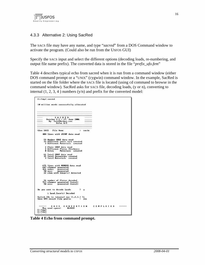
4.3.3 Alternative 2: Using SacRed The SACS file may have any name, and type “sacred” from a DOS Command window to activate the program. (Could also be run from the USFOS GUI) Specify the SACS input and select the different options (decoding loads, re-numbering, and output file name prefix). The converted data is stored in the file “prefix_ufo.fem” Table 4 describes typical echo from sacred when it is run from a command window (either DOS command prompt or a “UNIX” (cygwin) command window. In the example, SacRed is started on the file folder where the SACS file is located (using cd command to browse in the command window). SacRed asks for SACS file, decoding loads, (y or n), converting to internal (1, 2, 3, 4 ) numbers (y/n) and prefix for the converted model:
Ta
Con
ble 4 Echo from command prompt.
verting structural models to USFOS 2008-04-01
17
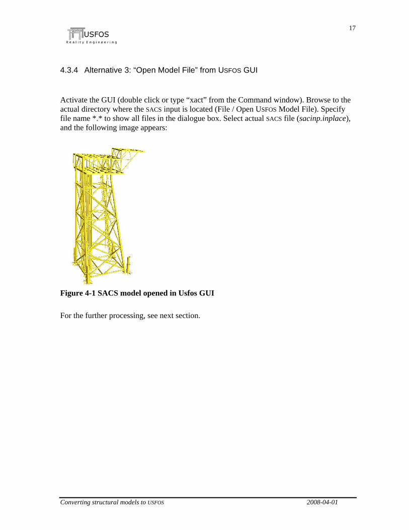
4.3.4 Alternative 3: “Open Model File” from USFOS GUI Activate the GUI (double click or type “xact” from the Command window). Browse to the actual directory where the SACS input is located (File / Open USFOS Model File). Specify file name *.* to show all files in the dialogue box. Select actual SACS file (sacinp.inplace), and the following image appears:
Figure 4-1 SACS model opened in Usfos GUI For the further processing, see next section.
Converting structural models to USFOS 2008-04-01

18
4.3.5 Analysis Setup using the USFOS GUI Select “Analysis SetUp” and specify the minimum input. Specify the model file name and press apply, and the Analysis Control Appears, (see Figure 4-5)
Figure 4-2 Analysis SetUp
Figure 4-3 “Create usfos model?”
Figure 4-4 Specify model file name
Converting structural models to USFOS 2008-04-01

19
Figure 4-5 The initial Analysis Control
If the model is ready to use, just press “Run”.
4.4 Foundation data The foundation data are not translated from the sacs psi file (SacRed may handle some soil data). The typical data needed to provide:
Extra nodes defining the pile tip Definition of the properties of the different soil layers Specifying piles from jacket towards the tip Pile diameter and thickness
4.5 Units The translators will normally try to convert all data to pure SI units (N, m, kg), and it is recommended to use these pure SI units. In particular if foundation, hydrodynamics or dynamic analyses are performed.
Converting structural models to USFOS 2008-04-01

20
4.6 Hints when creating the SACS model from scratch
Numbering (avoid using alphanumeric ID’s etc) Loads Boundary conditions Special data
4.7 Troubleshooting
Unknown sections Check .out file or fort.17 for messages Boundary conditions Not 100% translation of all elements Unrealistic element properties (extreme slender etc)
Converting structural models to USFOS 2008-04-01
21
5 STAAD structural files
5.1 Introduction STAAD is a widely used code, and structural models often exist in this format. STAAD is using same basic data as USFOS, and all relevant structural data could be derived from a STAAD text file, (with extension .std). Below, the conversion process is described step by step.
5.2 Staad File Format basic commands The STAAD input syntax is easy to read (by humans) and some basic commands are listed:
UNIT : Defines Units JOINT : Defines nodal numbers and coordinates (x,y,z) MEMBER INCIDENCES : Defines beam element connectivity ELEMENT INCIDENCES : Defines plate element connectivity MEMBER PROPERTY : Defines cross sections + assigning to elements …
Table 5 and Table 6 give examples of typical STAAD input records, which are decoded by Usfos. The STAAD input records are translated to the corresponding USFOS record during the automatic conversion, and written to a new file. All node and element numbers are kept. Load cases and load labels are translated and are available during the SetUp. By default, the Y-axis is the vertical axis in STAAD. During the conversion, it is possible to rotate the structure to get the Z axis upwards. (Automatically in XACT, optional in stadred).
Converting structural models to USFOS 2008-04-01

22
T
C
UNIT METER KN * JOINT COORDINATES 500 175.77 28.35 -1.68; 501 175.77 28.35 -18.4; 504 175.77 29.05 -1.68; 506 175.77 29.05 -18.4; 508 175.77 28.025 -18.4; 509 175.77 28.1 -18.4; 510 175.77 28.25 -18.4; 511 184.63 28.4 -18.4; 512 184.63 28.5 -18.4; * MEMBER INCIDENCES 1 8693 526; 2 8723 8764; 3 8694 508; 4 8724 8770; 5 500 529; 7 501 514; 9 526 1043; 10 8737 1045; 11 8757 1046; 12 508 1044; 13 504 8766; 14 537 8779; 15 506 8768; 16 513 8775; 17 528 1001; 18 510 1004; 21 508 509; 22 509 510; * ELEMENT INCIDENCES SHELL 1500 1003 1004 1035 1006; 1501 1004 1005 1007 1035; 1502 1005 1025 1026 1014; 1503 1014 1026 1027 1007; 1504 1008 1037 1004 1003; 1505 1037 1009 1005 1004; * SUPPORTS 8736 8755 PINNED * DEFINE MATERIAL START ISOTROPIC STEEL E 2.05e+008 POISSON 0.3 DENSITY 77 ALPHA 1.2e-005 DAMP 0.03 END DEFINE MATERIAL * *SECTION LIBRARY START USER TABLE TABLE 1 UNIT MMS KN WIDE FLANGE PG1_1500X427 54360 1500 19 450 30 1.932E+010 4.564E+008 1.139E+007 27360 27000 PG2_1350X330 * TABLE 2 UNIT MMS KNS PIPE PIP457.2X19 457.2 419.2 26156 26156 PIP400X20 400 360 23876 23876 * END * UNITS METER KN MEMBER PROPERTY BRITISH 1003 1007 1034 1042 1048 1052 TO 1057 1065 1527 TO 1529 - 1530 TABLE ST TUBE TH 0.02 WT 0.3 DT 0.9 1591 TO 1623 TABLE ST TUB25025010.0 MEMBER PROPERTY EUROPEAN 1019 TO 1027 1030 1049 1058 TO 1062 1066 TO 1070 1580 TABLE ST IPE450 1031 1032 1035 TO 1040 1043 TO 1045 1047 1063 1072 TO 1074 1576 - 1577 TABLE ST IPE600 1581 TO 1584 1587 TO 1590 TABLE ST HE300B * * * MEMBERS FROM USER TABLES 1000 TO 1002 1005 1006 1009 TO 1018 1028 1029 1033 1041 1046 1050 1051 1064 - 1071 1575 1578 1579 UPTABLE 1 PG4_900X175 9 TO 12 17 18 UPTABLE 2 PIP406X25.4 13 15 1561 1563 UPTABLE 1 C12_950X607 32 47 UPTABLE 1 C11_950X626 31 46 UPTABLE 1 C10_950X666 30 45 UPTABLE 1 C9_950X705 * * *DEFINE CONSTANTS UNIT MMS KN CONSTANTS MATERIAL STEEL ALL * *DECK PLATES ELEMENT PROPERTY 1500 TO 1526 1585 1586 THICKNESS 10 ***
able 5 Typical STAAD input records
onverting structural models to USFOS 2008-04-01
23
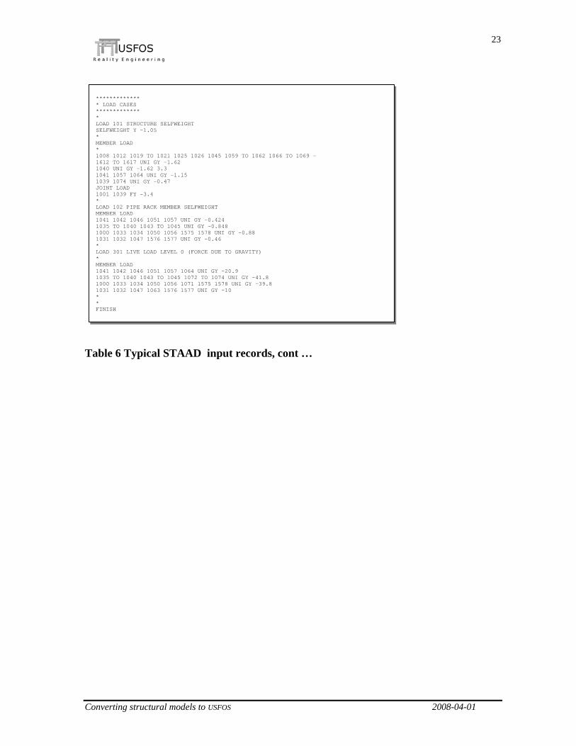
************* * LOAD CASES ************* * LOAD 101 STRUCTURE SELFWEIGHT SELFWEIGHT Y -1.05 * MEMBER LOAD * 1008 1012 1019 TO 1021 1025 1026 1045 1059 TO 1062 1066 TO 1069 - 1612 TO 1617 UNI GY -1.62 1040 UNI GY -1.62 3.3 1041 1057 1064 UNI GY -1.15 1039 1074 UNI GY -0.47 JOINT LOAD 1001 1039 FY -3.4 * LOAD 102 PIPE RACK MEMBER SELFWEIGHT MEMBER LOAD 1041 1042 1046 1051 1057 UNI GY -0.424 1035 TO 1040 1043 TO 1045 UNI GY -0.848 1000 1033 1034 1050 1056 1575 1578 UNI GY -0.88 1031 1032 1047 1576 1577 UNI GY -0.46 * LOAD 301 LIVE LOAD LEVEL 0 (FORCE DUE TO GRAVITY) * MEMBER LOAD 1041 1042 1046 1051 1057 1064 UNI GY -20.9 1035 TO 1040 1043 TO 1045 1072 TO 1074 UNI GY -41.8 1000 1033 1034 1050 1056 1071 1575 1578 UNI GY -39.8 1031 1032 1047 1063 1576 1577 UNI GY -10 * * FINISH
Table 6 Typical STAAD input records, cont …
Converting structural models to USFOS 2008-04-01

24
5.3 Converting one STAAD files to USFOS file format
5.3.1 Introduction The STAAD file could be translated to USFOS format in any of the three ways:
Running StruMan (General file converter) Running StadRed (stand alone STAAD translator) “Open Model File” from the USFOS GUI.
5.3.2 Alternative 1: Using StruMan Following has to be done:
Copy (or rename) the STAAD input to a file with extension .fem (f.ex staad.fem) Create a new file, (STRUMAN control file), which contains only one command, see
Table 7. Run STRUMAN either from the USFOS GUI or from a DOS-Command window. Specify “STRUMAN” (or the file name you have selected for the struman control commands), when asked for “Control file prefix” and give “staad” for the “Structural File Prefix”. Specify a suitable “Result File Prefix”, (f ex res) The converted file is stored in the file “res_ufo.fem”. If the conversion fails, the error messages are printed either on screen, on the file “res.out” or on “fort.17”. The control file for STRUMAN is specified below.
C
# Control file for StruMan # ufo ! Export Model To Usfos File Format ' -------------------- E O F ----------------------
Table 7 Contents of struman contol file: struman.fem
onverting structural models to USFOS 2008-04-01

25
5.3.3 Alternative 2: Using StadRed The STAAD file may have any name, and type “stadred” from a DOS Command window to activate the program. (Could also be run from the USFOS GUI) Specify the STAAD input and select the different options (decoding loads, re-numbering, and output file name prefix). The converted data is stored in the file “prefix_ufo.fem” Table 4 describes typical echo from StadRed when it is run from a command window (either DOS command prompt or a “UNIX” (cygwin) command window. In the example, StadRed is started on the file folder where the STAAD file is located (using cd command to browse in the command window). StadRed asks for STAAD file, decoding loads, (y or n), to swap Y-Z axis (Z-becomes the vertical axis), and prefix for the converted model: ---------------------------------------------
--------------------------------------------- --------------------------------------------- ------- S T A D R E D -------- ------- Version 1.6 / 15 Dec 2004 -------- ------- Supported By -------- ------- -------- ------- [email protected] -------- --------------------------------------------- --------------------------------------------- --------------------------------------------- Give STAAD File Name : demo.std 55 *JOINT COORDINATES* lines read. Total 164 Nodes Generated. 57 lines with boundary data read 51 *MEMBER INCIDENCES* lines read. 208 Beam Elements. 29 Plate Elements. Total 237 Elements Detected. Do you want to decode Loads ? y Do you want to Swap Y-and Z axes ? y Give UFO result file prefix : model
Table 8 Echo from command prompt.
Converting structural models to USFOS 2008-04-01

26
5.3.4 Alternative 3: “Open Model File” from USFOS GUI Activate the GUI (double click or type “xact” from the Command window). Browse to the actual directory where the STAAD input is located (File / Open USFOS Model File). Files with extension .std and .fem are shown in the dialogue box. Select actual STAAD file (staad.std), and the following image appears:
Figure 5-1 STAAD model opened in Usfos GUI For the further processing, see next section.
Converting structural models to USFOS 2008-04-01

27
5.3.5 Analysis Setup using the USFOS GUI Select “Analysis SetUp” and specify the minimum input. Specify the model file name and press apply, and the Analysis Control Appears, (see Figure 5-2).
Figure 5-2 Analysis SetUp. Load Labels from Abaqus is available.
Figure 5-3 “Create usfos model?”
Figure 5-4 Specify model file name
Converting structural models to USFOS 2008-04-01

28
Figure 5-5 The initial Analysis Control
If the model is ready to use, just press “Run”.
5.4 Units The translators will normally try to convert all data to pure SI units (N, m, kg), and it is recommended to use these pure SI units. In particular if foundation, hydrodynamics or dynamic analyses are performed.
5.5 Hints when creating the STAAD model from scratch
Numbering (avoid using alphanumeric ID’s etc) Use European or British Profiles. Avoid long names on User Table profiles. Skip dummy load definitions (just comment out using “*”) Boundary conditions. (PIN or FIX)
5.6 Troubleshooting
Unknown sections Check .out file or fort.17 for messages Boundary conditions Not 100% translation of all elements Unrealistic element properties (extreme slender etc)
Converting structural models to USFOS 2008-04-01

29
6 ABAQUS CAE structural files
6.1 Introduction Two versions of abaqus input are decoded, (Pataba syntax and CAE). However, only a sub set of the possible abaqus options are read and interpreted. Table 9 describes the typical abaqus cae language. Tab
Con
*Heading Abaqus input deck of example frame ** Job name: Frame-model Model name: Model-1 *Preprint, echo=NO, model=NO, history=NO, contact=NO ** ** PARTS ** *Part, name=Frame *Node 1, 7.5, 100., 0. 2, 7.5, 100., 7.5 .............. 61, 30., 66.6666641, 30. 62, 30., 0., 30. *Element, type=S4 1, 4, 1, 2, 3 2, 3, 2, 5, 6 3, 6, 5, 7, 8 .............. 31, 2, 1, 49, 21 32, 38, 39, 50, 45 *Element, type=B31 33, 21, 45 34, 46, 22 .............. 159, 29, 46 160, 26, 47 *Nset, nset=_PickedSet18, internal, generate 1, 50, 1 *Elset, elset=_PickedSet18, internal, generate 1, 32, 1 ** Section: Platform *Shell Section, elset=_PickedSet34, material=Steel 0.05, 5 ** Region: (Brace:Picked), (Beam Orientation:Picked) *Elset, elset=_I2, internal 33, 34, 35, 36, 37, 38, 39, 40, 43, 44, 46, 48 ** Section: Brace Profile: Brace *Beam Section, elset=_I2, material=Steel, temperature=GRADIENTS, section=PIPE 0.3, 0.05 0.,0.,-1. ** Section: Beam-main Profile: Beam-main *Beam Section, elset=_PickedSet37, material=Steel, temperature=GRADIENTS, section=PIPE 1., 0.1 0.,0.,-1. *Material, name=Steel *Density 7850., *Elastic 2.07e+11, 0.3
le 9 Typical ABAQUS CAS input records
verting structural models to USFOS 2008-04-01

30
The conversion of Abaqus file is similar to the SACS conversion. StruMan will automatically detect the abaqus language and translate/export. To open an abaqus model in XACT, specify *.* in the file menu (similar to SACS) and open.
Figure 6-1 Abaqus CAE model imported to USFOS.
Converting structural models to USFOS 2008-04-01