converting autonomous access points to lightweight mode · reverting to a previous release using...
TRANSCRIPT

Converting Autonomous Access Points toLightweight Mode
• Information About Converting Autonomous Access Points to Lightweight Mode, page 2
• Restrictions for Converting Autonomous Access Points to Lightweight Mode, page 2
• Converting Autonomous Access Points to Lightweight Mode, page 2
• Reverting from Lightweight Mode to Autonomous Mode, page 3
• Authorizing Access Points, page 4
• Configuring VLAN Tagging for CAPWAP Frames from Access Points, page 10
• Using DHCP Option 43 and DHCP Option 60, page 11
• Troubleshooting the Access Point Join Process, page 12
• Sending Debug Commands to Access Points Converted to Lightweight Mode, page 17
• Understanding How Converted Access Points Send Crash Information to the Controller, page 17
• Understanding How Converted Access Points Send Radio Core Dumps to the Controller, page 17
• Uploading Memory Core Dumps from Converted Access Points, page 19
• Viewing the AP Crash Log Information, page 20
• Displaying MAC Addresses for Converted Access Points, page 21
• Disabling the Reset Button on Access Points Converted to Lightweight Mode, page 21
• Configuring a Static IP Address on a Lightweight Access Point, page 21
• Supporting Oversized Access Point Images, page 24
Cisco Wireless LAN Controller Configuration Guide, Release 7.4 OL-28744-01 1

Information About Converting Autonomous Access Points toLightweight Mode
You can convert any autonomous mode Cisco Aironet access point, to lightweight mode. When you upgradeone of these access points to lightweight mode, the access point communicates with a controller and receivesa configuration and software image from the controller.
See the Upgrading Autonomous Cisco Aironet Access Points to Lightweight Mode document for instructionsto upgrade an autonomous access point to lightweight mode:
http://www.cisco.com/c/en/us/td/docs/wireless/controller/8-0/configuration-guide/b_cg80/b_cg80_chapter_01101010.html
The following are some guidelines for converting autonomous APs to lightweight mode APs:
• All Cisco lightweight access points support 16 BSSIDs per radio and a total of 16 wireless LANs peraccess point. When a converted access point associates with a controller, wireless LANs with IDs 1through 16 are pushed to the access point if the AP is part of the default AP group on the controller.You can use other AP group configurations to push other wireless LANs to the new AP.
When a 802.11ac module (the RM3000AC) is added to a 3600 AP, you can have only 8 wireless LANson the 802.11a/n/ac radio.
• Access points converted to lightweight mode must get an IP address and discover the controller usingDHCP, DNS, or IP subnet broadcast.
Restrictions for Converting Autonomous Access Points toLightweight Mode
• Access points converted to lightweight mode do not supportWireless Domain Services (WDS). Convertedaccess points communicate only with Cisco wireless LAN controllers and cannot communicate withWDS devices. However, the controller provides functionality that is equivalent toWDSwhen the accesspoint associates to it.
• After you convert an access point to lightweight mode, the console port provides read-only access tothe unit.
Converting Autonomous Access Points to Lightweight Mode1 Download the CAPWAP file matching your access point model from Cisco.com. Two types of CAPWAP
files are available:
• Fully functional CAPWAP files, identified by the k9w8 string in their name. When booting thisimage, the AP is fully functional and can join a controller to obtain its configuration.
• Recovery mode CAPWAP files, identified by the rcvk9w8 string in their name. These files are smallerthan the fully functional k9w8 CAPWAP files. When booting rcvk9w8 files, the AP can join acontroller to download a fully functional image. The AP will then reboot, use the fully functionalimage and rejoin a controller to obtain its configuration.
Cisco Wireless LAN Controller Configuration Guide, Release 7.42 OL-28744-01
Converting Autonomous Access Points to Lightweight ModeInformation About Converting Autonomous Access Points to Lightweight Mode

2 position the image on an FTP server
3 Configure the AP to connect to the FTP server as a FTP client. This is done under global configurationmode, with the command ip ftp username, and ip ftp password. For example:Ap#configure terminalap(config)#ip ftp username ciscoap(config)#ip ftp password Cisco123ap(config)#exit
4 Once the parameters are configured, you can start the download process on the AP. Use the archivedownload-sw command, with the /force-reload argument to have the AP reboot at the end of the cycle,and /overwrite to replace the autonomous code with the CAPWAP code. See the following example:ap#archive download-sw /force-reload /overwriteftp://10.100.1.31/ap3g2-rcvk9w8-tar.152-4.JB6.tarexamining image...Loading ap3g2-rcvk9w8-tar.152-4.JB6.tarextracting info (273 bytes)!Image info:
Version Suffix: rcvk9w8-Image Name: ap3g2-rcvk9w8-mxVersion Directory: ap3g2-rcvk9w8-mxIos Image Size: 2335232Total Image Size: 2335232Image Feature: WIRELESS LAN|CAPWAP|RECOVERYImage Family: ap3g2Wireless Switch Management Version: 3.0.51.0
Extracting files...ap3g2-rcvk9w8-mx/ (directory) 0 (bytes)extracting ap3g2-rcvk9w8-mx/ap3g2-rcvk9w8-mx (2327653 bytes)!!!!!!!!!extracting ap3g2-rcvk9w8-mx/info (273 bytes)The AP reboots into lightweight mode and looks for a controller.
Reverting from Lightweight Mode to Autonomous ModeAfter you convert an autonomous access point to lightweight mode, you can convert the access point from alightweight unit back to an autonomous unit by loading a Cisco IOS release that supports autonomous mode.If the access point is associated to a controller, you can use the controller to load the Cisco IOS release. If theaccess point is not associated to a controller, you can load the Cisco IOS release using TFTP. In either method,the access point must be able to access a TFTP server that contains the Cisco IOS release to be loaded.
Reverting to a Previous Release (CLI)
Step 1 Log on to the CLI on the controller to which the access point is associated.Step 2 Revert from lightweight mode, by entering this command:
config ap tftp-downgrade tftp-server-ip-address filename access-point-name
Step 3 Wait until the access point reboots and reconfigure the access point using the CLI or GUI.
Cisco Wireless LAN Controller Configuration Guide, Release 7.4 OL-28744-01 3
Converting Autonomous Access Points to Lightweight ModeReverting from Lightweight Mode to Autonomous Mode

Reverting to a Previous Release Using the MODE Button and a TFTP Server
Step 1 Configure the PC on which your TFTP server software runs with a static IP address in the range of 10.0.0.2 to 10.0.0.30.Step 2 Make sure that the PC contains the access point image file (such as ap3g2-k9w7-tar.152-4.JB4.tar for a 2700 or 3700
series access point) in the TFTP server folder and that the TFTP server is activated.Step 3 Rename the access point image file in the TFTP server folder to ap3g2-k9w7-tar.default for a 2700 or a 3700 series
access point.Step 4 Connect the PC to the access point using a Category 5 (CAT5) Ethernet cable.Step 5 Disconnect power from the access point.Step 6 Press and hold theMODE button while you reconnect power to the access point.
The MODE button on the access point must be enabled. Follow the steps in the Disabling the Reset Button onAccess Points Converted to Lightweight Mode to select the status of the access point MODE button.
Note
Step 7 Hold theMODE button until the status LED turns red (approximately 20 to 30 seconds), and release the MODE button.Step 8 Wait until the access point reboots as indicated by all LEDs turning green followed by the Status LED blinking green.Step 9 After the access point reboots, reconfigure the access point using the GUI or the CLI.
Authorizing Access PointsIn controller software releases prior to 5.2, the controller may either use self-signed certificates (SSCs) toauthenticate access points or send the authorization information to a RADIUS server (if access points havemanufactured-installed certificates [MICs]). In controller software release 5.2 or later releases, you canconfigure the controller to use a local significant certificate (LSC).
Access points manufactured after July 18, 2005 contain a manufactured-installed certificate (MIC). Thecontroller can use this certificate to authenticate the access points. Alternatively, you can use an authenticationlist on the controller or an external RADIUS server.
Authorizing Access Points Using SSCsThe Control and Provisioning of Wireless Access Points protocol (CAPWAP) secures the controlcommunication between the access point and controller by a secure key distribution requiring X.509 certificateson both the access point and controller. CAPWAP relies on provisioning of the X.509 certificates. CiscoAironet access points shipped before July 18, 2005 do not have a MIC, so these access points create an SSCwhen upgraded to operate in lightweight mode. Controllers are programmed to accept local SSCs forauthentication of specific access points and do not forward those authentication requests to a RADIUS server.This behavior is acceptable and secure.
Authorizing Access Points for Virtual Controllers Using SSCVirtual controllers use SSC certificates instead of Manufacturing Installed Certificates (MIC) used by physicalcontrollers. You can configure the controller to allow an AP to validate the SSC of the virtual controller.
Cisco Wireless LAN Controller Configuration Guide, Release 7.44 OL-28744-01
Converting Autonomous Access Points to Lightweight ModeReverting to a Previous Release Using the MODE Button and a TFTP Server

When an AP validates the SSC, the AP checks if the hash key of the virtual controller matches the hash keystored in its flash. If a match is found, the AP associates with the controller. If a match is not found, thevalidation fails and the AP disconnects from the controller and restarts the discovery process. By default, hashvalidation is enabled. An AP must have the virtual controller hash key in its flash before associating with thevirtual controller. If you disable hash validation of the SSC, the AP bypasses the hash validation and directlymoves to the Run state. APs can associate with a physical controller, download the hash keys and then associatewith a virtual controller. If the AP is associated with a physical controller and hash validation is disabled, theAP associates with any virtual controller without hash validation. The hash key of the virtual controller canbe configured for a mobility group member. This hash key gets pushed to the APs, so that the APs can validatethe hash key of the controller.
Configuring SSC (GUI)
Step 1 Choose Security > Certificate > SSC to open the Self Significant Certificates (SSC) page.The SSC device certification details are displayed.
Step 2 Select the Enable SSC Hash Validation check box to enable the validation of the hash key.Step 3 Click Apply to commit your changes.
Configuring SSC (CLI)
Step 1 To configure hash validation of SSC, enter this command:config certificate ssc hash validation {enable | disable}
Step 2 To see the hash key details, enter this command:show certificate ssc
Authorizing Access Points Using MICsYou can configure controllers to use RADIUS servers to authorize access points using MICs. The controlleruses an access point’s MAC address as both the username and password when sending the information to aRADIUS server. For example, if the MAC address of the access point is 000b85229a70, both the usernameand password used by the controller to authorize the access point are 000b85229a70.
The lack of a strong password by the use of the access point’s MAC address should not be an issue becausethe controller uses MIC to authenticate the access point prior to authorizing the access point through theRADIUS server. Using MIC provides strong authentication.
Note
Cisco Wireless LAN Controller Configuration Guide, Release 7.4 OL-28744-01 5
Converting Autonomous Access Points to Lightweight ModeAuthorizing Access Points Using MICs

If you use the MAC address as the username and password for access point authentication on a RADIUSAAA server, do not use the same AAA server for client authentication.
Note
Authorizing Access Points Using LSCsYou can use an LSC if you want your own public key infrastructure (PKI) to provide better security, to havecontrol of your certificate authority (CA), and to define policies, restrictions, and usages on the generatedcertificates.
The LSCCA certificate is installed on access points and controllers. You need to provision the device certificateon the access point. The access point gets a signed X.509 certificate by sending a certRequest to the controller.The controller acts as a CA proxy and receives the certRequest signed by the CA for the access point.
When the CA server is in manual mode and if there is an AP entry in the LSC SCEP table that is pendingenrollment, the controller waits for the CA server to send a pending response. If there is no response fromthe CA server, the controller retries a total of three times to get a response, after which the fallback modecomes into effect where the AP provisioning times out and the AP reboots and comes up with MIC.
Note
LSC on controller does not take password challenge. Therefore, for LSC to work, you must disablepassword challenge on the CA server.
Note
Configuring Locally Significant Certificates (GUI)
Step 1 Choose Security > Certificate > LSC to open the Local Significant Certificates (LSC) - General page.Step 2 Select the Enable LSC on Controller check box to enable the LSC on the system.Step 3 In the CA Server URL text box, enter the URL to the CA server. You can enter either a domain name or an IP address.Step 4 In the Params text boxes, enter the parameters for the device certificate. The key size is a value from 384 to 2048 (in
bits), and the default value is 2048.Step 5 Click Apply to commit your changes.Step 6 To add the CA certificate into the controller’s CA certificate database, hover your cursor over the blue drop-down arrow
for the certificate type and choose Add.Step 7 Choose the AP Provisioning tab to open the Local Significant Certificates (LSC) - AP Provisioning page.Step 8 Select the Enable check box and click Update to provision the LSC on the access point.Step 9 When a message appears indicating that the access points will be rebooted, click OK.Step 10 In the Number of Attempts to LSC text box, enter the number of times that the access point attempts to join the controller
using an LSC before the access point reverts to the default certificate (MIC or SSC). The range is 0 to 255 (inclusive),and the default value is 3.
Cisco Wireless LAN Controller Configuration Guide, Release 7.46 OL-28744-01
Converting Autonomous Access Points to Lightweight ModeAuthorizing Access Points Using LSCs
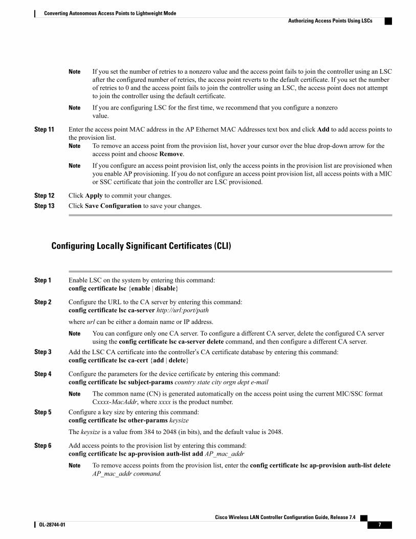
If you set the number of retries to a nonzero value and the access point fails to join the controller using an LSCafter the configured number of retries, the access point reverts to the default certificate. If you set the numberof retries to 0 and the access point fails to join the controller using an LSC, the access point does not attemptto join the controller using the default certificate.
Note
If you are configuring LSC for the first time, we recommend that you configure a nonzerovalue.
Note
Step 11 Enter the access point MAC address in the AP Ethernet MAC Addresses text box and click Add to add access points tothe provision list.
To remove an access point from the provision list, hover your cursor over the blue drop-down arrow for theaccess point and choose Remove.
Note
If you configure an access point provision list, only the access points in the provision list are provisioned whenyou enable AP provisioning. If you do not configure an access point provision list, all access points with a MICor SSC certificate that join the controller are LSC provisioned.
Note
Step 12 Click Apply to commit your changes.Step 13 Click Save Configuration to save your changes.
Configuring Locally Significant Certificates (CLI)
Step 1 Enable LSC on the system by entering this command:config certificate lsc {enable | disable}
Step 2 Configure the URL to the CA server by entering this command:config certificate lsc ca-server http://url:port/path
where url can be either a domain name or IP address.
You can configure only one CA server. To configure a different CA server, delete the configured CA serverusing the config certificate lsc ca-server delete command, and then configure a different CA server.
Note
Step 3 Add the LSC CA certificate into the controller’s CA certificate database by entering this command:config certificate lsc ca-cert {add | delete}
Step 4 Configure the parameters for the device certificate by entering this command:config certificate lsc subject-params country state city orgn dept e-mail
The common name (CN) is generated automatically on the access point using the current MIC/SSC formatCxxxx-MacAddr, where xxxx is the product number.
Note
Step 5 Configure a key size by entering this command:config certificate lsc other-params keysize
The keysize is a value from 384 to 2048 (in bits), and the default value is 2048.
Step 6 Add access points to the provision list by entering this command:config certificate lsc ap-provision auth-list add AP_mac_addr
To remove access points from the provision list, enter the config certificate lsc ap-provision auth-list deleteAP_mac_addr command.
Note
Cisco Wireless LAN Controller Configuration Guide, Release 7.4 OL-28744-01 7
Converting Autonomous Access Points to Lightweight ModeAuthorizing Access Points Using LSCs
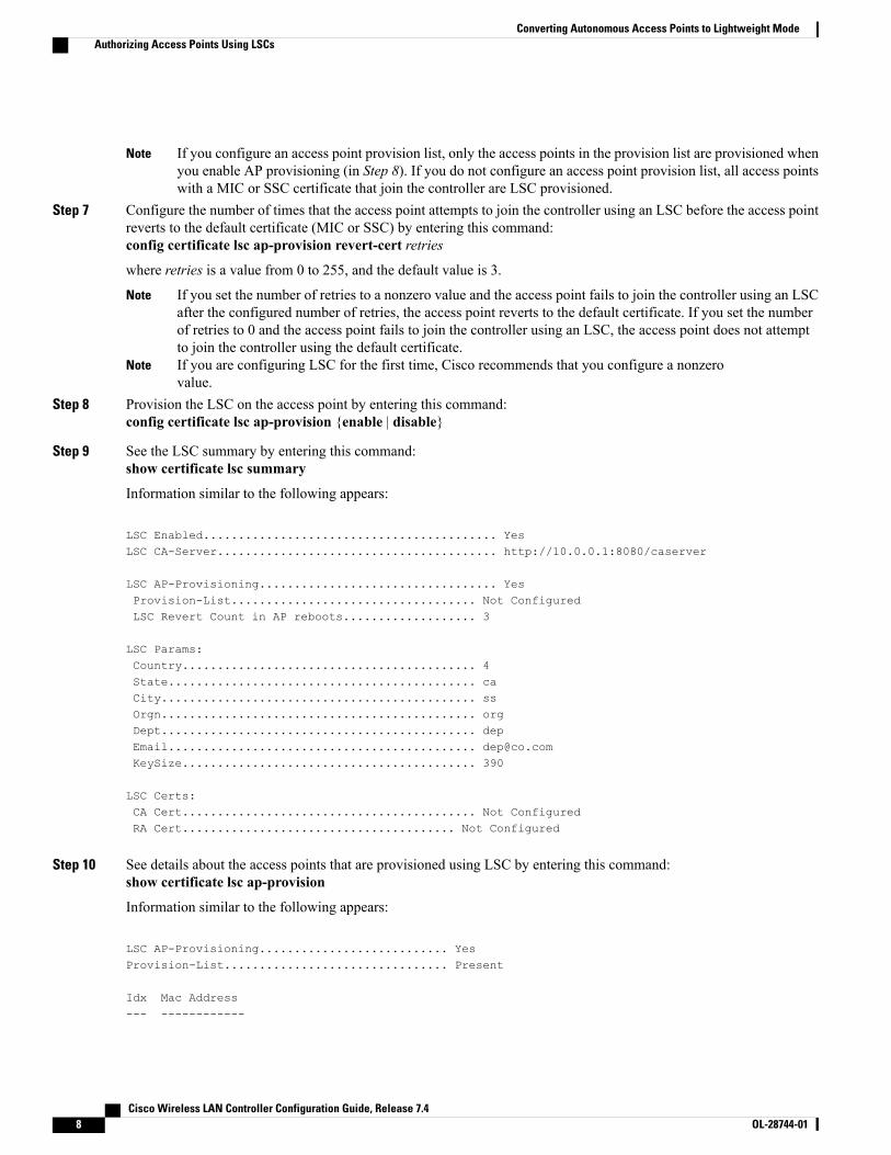
If you configure an access point provision list, only the access points in the provision list are provisioned whenyou enable AP provisioning (in Step 8). If you do not configure an access point provision list, all access pointswith a MIC or SSC certificate that join the controller are LSC provisioned.
Note
Step 7 Configure the number of times that the access point attempts to join the controller using an LSC before the access pointreverts to the default certificate (MIC or SSC) by entering this command:config certificate lsc ap-provision revert-cert retries
where retries is a value from 0 to 255, and the default value is 3.
If you set the number of retries to a nonzero value and the access point fails to join the controller using an LSCafter the configured number of retries, the access point reverts to the default certificate. If you set the numberof retries to 0 and the access point fails to join the controller using an LSC, the access point does not attemptto join the controller using the default certificate.
Note
If you are configuring LSC for the first time, Cisco recommends that you configure a nonzerovalue.
Note
Step 8 Provision the LSC on the access point by entering this command:config certificate lsc ap-provision {enable | disable}
Step 9 See the LSC summary by entering this command:show certificate lsc summary
Information similar to the following appears:
LSC Enabled.......................................... YesLSC CA-Server........................................ http://10.0.0.1:8080/caserver
LSC AP-Provisioning.................................. YesProvision-List................................... Not ConfiguredLSC Revert Count in AP reboots................... 3
LSC Params:Country.......................................... 4State............................................ caCity............................................. ssOrgn............................................. orgDept............................................. depEmail............................................ [email protected].......................................... 390
LSC Certs:CA Cert.......................................... Not ConfiguredRA Cert....................................... Not Configured
Step 10 See details about the access points that are provisioned using LSC by entering this command:show certificate lsc ap-provision
Information similar to the following appears:
LSC AP-Provisioning........................... YesProvision-List................................ Present
Idx Mac Address--- ------------
Cisco Wireless LAN Controller Configuration Guide, Release 7.48 OL-28744-01
Converting Autonomous Access Points to Lightweight ModeAuthorizing Access Points Using LSCs

1 00:18:74:c7:c0:90
Authorizing Access Points (GUI)
Step 1 Choose Security > AAA > AP Policies to open the AP Policies page.Step 2 If you want the access point to accept self-signed certificates (SSCs), manufactured-installed certificates (MICs), or local
significant certificates (LSCs), select the appropriate check box.Step 3 If you want the access points to be authorized using a AAA RADIUS server, select the Authorize MIC APs against
auth-list or AAA check box.Step 4 If you want the access points to be authorized using an LSC, select the Authorize LSC APs against auth-list check
box.Enter the Ethernet MAC address for all APs except when in bridge mode (where you need to enter the radioMac address).
Step 5 Click Apply to commit your changes.Step 6 Follow these steps to add an access point to the controller’s authorization list:
a) Click Add to access the Add AP to Authorization List area.b) In the MAC Address text box, enter the MAC address of the access point.c) From the Certificate Type drop-down list, chooseMIC, SSC, or LSC.d) Click Add. The access point appears in the access point authorization list.
To remove an access point from the authorization list, hover your cursor over the blue drop-down arrow forthe access point and choose Remove.
Note
To search for a specific access point in the authorization list, enter the MAC address of the access point inthe Search by MAC text box and click Search.
Note
Authorizing Access Points (CLI)• Configure an access point authorization policy by entering this command:config auth-list ap-policy {authorize-ap {enable | disable} | authorize-lsc-ap {enable | disable}}
• Configure an access point to accept manufactured-installed certificates (MICs), self-signed certificates(SSCs), or local significant certificates (LSCs) by entering this command:config auth-list ap-policy {mic | ssc | lsc {enable | disable}}
• Configure the user name to be used in access point authorization requests.config auth-list ap-policy {authorize-ap username {ap_name | ap_mac | both}}
• Add an access point to the authorization list by entering this command:config auth-list add {mic | ssc | lsc} ap_mac [ap_key]
where ap_key is an optional key hash value equal to 20 bytes or 40 digits.
Cisco Wireless LAN Controller Configuration Guide, Release 7.4 OL-28744-01 9
Converting Autonomous Access Points to Lightweight ModeAuthorizing Access Points (GUI)

To delete an access point from the authorization list, enter this command: config auth-list delete ap_mac.Note
• See the access point authorization list by entering this command:show auth-list
Configuring VLAN Tagging for CAPWAP Frames from AccessPoints
Information About VLAN Tagging for CAPWAP Frames from Access PointsYou can configure VLAN tagging on the Ethernet interface either directly on the AP console or through thecontroller. The configuration is saved in the flash memory and all CAPWAP frames use the VLAN tag asconfigured, along with all the locally switched traffic, which is not mapped to a VLAN.
This feature is not supported on mesh access points that are in bridge mode.
Configuring VLAN Tagging for CAPWAP Frames from Access Points (GUI)
Step 1 ChooseWireless > Access Points > All APs to open the All APs page.Step 2 Click the AP name from the list of AP names to open the Details page for the AP.Step 3 Click the Advanced tab.Step 4 In the VLAN Tagging area, select the VLAN Tagging check box.Step 5 In the Trunk VLAN ID text box, enter an ID.
If the access point is unable to route traffic through the specified trunk VLAN after about 10 minutes, the access pointperforms a recovery procedure by rebooting and sending CAPWAP frames in untagged mode to try and reassociate withthe controller. The controller sends a trap to a trap server such as the Cisco Prime Infrastructure, which indicates thefailure of the trunk VLAN.
If the access point is unable to route traffic through the specified trunk VLAN, it untags the packets and reassociateswith the controller. The controller sends a trap to a trap server such as the Cisco Prime Infrastructure, which indicatesthe failure of the trunk VLAN.
If the trunk VLAN ID is 0, the access point untags the CAPWAP frames.
The VLAN Tag status is displayed showing whether the AP tags or untags the CAPWAP frames.
Step 6 Click Apply.Step 7 You are prompted with a warning message saying that the configuration will result in a reboot of the access point. Click
OK to continue.Step 8 Click Save Configuration.
Cisco Wireless LAN Controller Configuration Guide, Release 7.410 OL-28744-01
Converting Autonomous Access Points to Lightweight ModeConfiguring VLAN Tagging for CAPWAP Frames from Access Points

What to Do Next
After the configuration, the switch or other equipment connected to the Ethernet interface of the AP must alsobe configured to support tagged Ethernet frames.
Configuring VLAN Tagging for CAPWAP Frames from Access Points (CLI)
Step 1 Configure VLAN tagging for CAPWAP frames from access points by entering this command:config ap ethernet tag {disable | id vlan-id} {ap-name | all}
Step 2 You can see VLAN tagging information for an AP or all APs by entering this command:show ap ethernet tag {summary | ap-name}
Using DHCP Option 43 and DHCP Option 60Cisco Aironet access points use the type-length-value (TLV) format for DHCP option 43. DHCP servers mustbe programmed to return the option based on the access point’s DHCP Vendor Class Identifier (VCI) string(DHCP option 60).
This table lists the VCI strings for Cisco access points capable of operating in lightweight mode.
Table 1: VCI Strings For Lightweight Access Points
VCI StringAccess Point
Cisco AP c1040Cisco Aironet 1040 Series
Cisco AP c1130Cisco Aironet 1130 Series
Cisco AP c1140Cisco Aironet 1140 Series
Cisco AP c1240Cisco Aironet 1240 Series
Cisco AP c1250Cisco Aironet 1250 Series
Cisco AP c1260Cisco Aironet 1260 Series
Cisco AP c1520Cisco Aironet 1520 Series
Cisco AP c1550Cisco Aironet 1550 Series
Cisco AP c1700Cisco Aironet 1700 Series
Cisco AP c2700Cisco Aironet 2700 Series
Cisco Wireless LAN Controller Configuration Guide, Release 7.4 OL-28744-01 11
Converting Autonomous Access Points to Lightweight ModeConfiguring VLAN Tagging for CAPWAP Frames from Access Points (CLI)

VCI StringAccess Point
Cisco AP c3600Cisco Aironet 3600 Series
Cisco AP c3700Cisco Aironet 3700 Series
Cisco AP c3500Cisco Aironet 3500 Series
Cisco AP c700Cisco Aironet 700 Series
Cisco AP801Cisco AP801 Embedded Access Point
Cisco AP802Cisco AP802 Embedded Access Point
The format of the TLV block is as follows:
• Type: 0xf1 (decimal 241)
• Length: Number of controller IP addresses * 4
• Value: List of the IP addresses of controller management interfaces
See the product documentation for your DHCP server for instructions on configuring DHCP option 43. TheUpgrading Autonomous Cisco Aironet Access Points to Lightweight Mode document contains example stepsfor configuring option 43 on a DHCP server.
If the access point is ordered with the Service Provider Option - AIR-OPT60-DHCP selected, the VCI stringfor that access point will be different than those listed above. The VCI string will have the “ServiceProvider”.For example, a 1260 with this option will return this VCI string: "Cisco AP c1260-ServiceProvider".
The controller IP address that you obtain from the DHCP server should be a unicast IP address. Do notconfigure the controller IP address as a multicast address when configuring DHCP Option 43.
Note
Troubleshooting the Access Point Join ProcessAccess points can fail to join a controller for many reasons such as a RADIUS authorization is pending,self-signed certificates are not enabled on the controller, the access point and controller’s regulatory domainsdo not match, and so on.
Controller software release 5.2 or later releases enable you to configure the access points to send allCAPWAP-related errors to a syslog server. You do not need to enable any debug commands on the controllerbecause all of the CAPWAP error messages can be viewed from the syslog server itself.
The state of the access point is not maintained on the controller until it receives a CAPWAP join request fromthe access point, so it can be difficult to determine why the CAPWAP discovery request from a certain accesspoint was rejected. In order to troubleshoot such joining issues without enabling CAPWAP debug commandson the controller, the controller collects information for all access points that send a discovery message to thiscontroller and maintains information for any access points that have successfully joined this controller.
Cisco Wireless LAN Controller Configuration Guide, Release 7.412 OL-28744-01
Converting Autonomous Access Points to Lightweight ModeTroubleshooting the Access Point Join Process

The controller collects all join-related information for each access point that sends a CAPWAP discoveryrequest to the controller. Collection begins with the first discovery message received from the access pointand ends with the last configuration payload sent from the controller to the access point.
You can view join-related information for the following numbers of access points:
When the controller is maintaining join-related information for the maximum number of access points, it doesnot collect information for any more access points.
If any of these conditions are met and the access point has not yet joined a controller, you can also configurea DHCP server to return a syslog server IP address to the access point using option 7 on the server. The accesspoint then starts sending all syslog messages to this IP address.
You can also configure the syslog server IP address through the access point CLI, provided the access pointis currently not connected to the controller by entering the capwap ap log-server syslog_server_IP_addresscommand.
When the access point joins a controller for the first time, the controller pushes the global syslog server IPaddress (the default is 255.255.255.255) to the access point. After that, the access point sends all syslogmessages to this IP address, until it is overridden by one of the following scenarios:
• The access point is still connected to the same controller, and the global syslog server IP addressconfiguration on the controller has been changed using the config ap syslog host globalsyslog_server_IP_address command. In this case, the controller pushes the new global syslog server IPaddress to the access point.
• The access point is still connected to the same controller, and a specific syslog server IP address hasbeen configured for the access point on the controller using the config ap syslog host specificCisco_APsyslog_server_IP_address command. In this case, the controller pushes the new specific syslog serverIP address to the access point.
• The access point gets disconnected from the controller, and the syslog server IP address has beenconfigured from the access point CLI using the lwapp ap log-server syslog_server_IP_address command.This command works only if the access point is not connected to any controller.
• The access point gets disconnected from the controller and joins another controller. In this case, the newcontroller pushes its global syslog server IP address to the access point.
Whenever a new syslog server IP address overrides the existing syslog server IP address, the old address iserased from persistent storage, and the new address is stored in its place. The access point also starts sendingall syslog messages to the new IP address, provided the access point can reach the syslog server IP address.
You can configure the syslog server for access points using the controller GUI and view the access point joininformation using the controller GUI or CLI.
When the name of the access point is modified using the config ap name new_name old_name command,then the new AP name is updated. You can view the new AP name updated in both the show ap join statssummary all as well as the show ap summary commands.
When an AP in a Release 8.0 image tries to join Cisco WLC, Release 8.3 (having Release 8.2 as theprimary image and Release 8.2.1 as the secondary image on Flash), the AP goes into a perpetual loop.(Note that the release numbers are used only as an example to illustrate the scenario of three differentimages and does not apply to the releases mentioned.) This loop occurs due to version mismatch. Afterthe download, when the AP compares its image with the Cisco WLC image, there will be a versionmismatch. The AP will start the entire process again, resulting in a loop.
Note
Cisco Wireless LAN Controller Configuration Guide, Release 7.4 OL-28744-01 13
Converting Autonomous Access Points to Lightweight ModeTroubleshooting the Access Point Join Process

Configuring the Syslog Server for Access Points (CLI)
Step 1 Perform one of the following:
• To configure a global syslog server for all access points that join this controller, enter this command:config ap syslog host global syslog_server_IP_address
By default, the global syslog server IPv4/IPv6 address for all access points is 255.255.255.255. Make surethat the access points can reach the subnet on which the syslog server resides before configuring the syslogserver on the controller. If the access points cannot reach this subnet, the access points are unable to sendout syslog messages.
Note
Only one Syslog Server is used for both IPv4 andIPv6.
Note
• To configure a syslog server for a specific access point, enter this command:config ap syslog host specific Cisco_AP syslog_server_IP_address
By default, the syslog server IPv4/IPv6 address for each access point is 0.0.0.0, which indicates that theaccess point is not yet set. When the default value is used, the global access point syslog server IP addressis pushed to the access point.
Note
Step 2 Enter the save config command to save your changes.Step 3 See the global syslog server settings for all access points that join the controller by entering this command:
show ap config global
Information similar to the following appears:
AP global system logging host.................... 255.255.255.255
Step 4 See the syslog server settings for a specific access point by entering this command:show ap config general Cisco_AP
Viewing Access Point Join InformationJoin statistics for an access point that sends a CAPWAP discovery request to the controller at least once aremaintained on the controller even if the access point is rebooted or disconnected. These statistics are removedonly when the controller is rebooted or when you choose to clear the statistics.
Viewing Access Point Join Information (GUI)
Step 1 ChooseMonitor > Statistics > AP Join to open the AP Join Stats page.
Cisco Wireless LAN Controller Configuration Guide, Release 7.414 OL-28744-01
Converting Autonomous Access Points to Lightweight ModeConfiguring the Syslog Server for Access Points (CLI)

This page lists all of the access points that are joined to the controller or that have tried to join. It shows the radio MACaddress, access point name, current join status, Ethernet MAC address, IP address, and last join time for each accesspoint.
The total number of access points appears in the upper right-hand corner of the page. If the list of access points spansmultiple pages, you can view these pages by clicking the page number links. Each page shows the join statistics for upto 25 access points.
If you want to remove an access point from the list, hover your cursor over the blue drop-down arrow for thataccess point and click Remove.
Note
If you want to clear the statistics for all access points and start over, click Clear Stats on AllAPs.
Note
Step 2 If you want to search for specific access points in the list of access points on the AP Join Stats page, follow these stepsto create a filter to display only access points that meet certain criteria (such as MAC address or access point name).
This feature is especially useful if your list of access points spans multiple pages, preventing you from viewingthem all at once.
Note
a) Click Change Filter to open the Search AP dialog box.b) Select one of the following check boxes to specify the criteria used when displaying access points:
•MAC Address—Enter the base radio MAC address of an access point.
• AP Name—Enter the name of an access point.When you enable one of these filters, the other filter is disabledautomatically.
Note
c) Click Find to commit your changes. Only the access points that match your search criteria appear on the AP JoinStats page, and the Current Filter parameter at the top of the page specifies the filter used to generate the list (forexample, MAC Address:00:1e:f7:75:0a:a0 or AP Name:pmsk-ap).
If you want to remove the filter and display the entire access point list, click ClearFilter.
Note
Step 3 To see detailed join statistics for a specific access point, click the radio MAC address of the access point. The AP JoinStats Detail page appears.This page provides information from the controller’s perspective on each phase of the join process and shows any errorsthat have occurred.
Viewing Access Point Join Information (CLI)Use these CLI commands to see access point join information:
• See the MAC addresses of all the access points that are joined to the controller or that have tried to joinby entering this command:
show ap join stats summary all
• See the last join error detail for a specific access point by entering this command:
show ap join stats summary ap_mac
where ap_mac is the MAC address of the 802.11 radio interface.
Cisco Wireless LAN Controller Configuration Guide, Release 7.4 OL-28744-01 15
Converting Autonomous Access Points to Lightweight ModeViewing Access Point Join Information

To obtain the MAC address of the 802.11 radio interface, enter the show interfacesDot11Radio 0 command on the access point.
Information similar to the following appears:
Is the AP currently connected to controller................ YesTime at which the AP joined this controller last time...... Aug 2112:50:36.061Type of error that occurred last........................... AP got or hasbeen disconnectedReason for error that occurred last........................ The AP hasbeen reset by the controllerTime at which the last join error occurred.............. Aug 2112:50:34.374
Note
• See all join-related statistics collected for a specific access point by entering this command:
show ap join stats detailed ap_mac
Information similar to the following appears:
Discovery phase statistics- Discovery requests received.............................. 2- Successful discovery responses sent...................... 2- Unsuccessful discovery request processing................ 0- Reason for last unsuccessful discovery attempt........... Not applicable- Time at last successful discovery attempt................ Aug 21 12:50:23.335- Time at last unsuccessful discovery attempt.............. Not applicable
Join phase statistics- Join requests received................................... 1- Successful join responses sent........................... 1- Unsuccessful join request processing..................... 1- Reason for last unsuccessful join attempt................ RADIUS authorizationis pending for the AP- Time at last successful join attempt..................... Aug 21 12:50:34.481- Time at last unsuccessful join attempt................... Aug 21 12:50:34.374
Configuration phase statistics- Configuration requests received.......................... 1- Successful configuration responses sent.................. 1- Unsuccessful configuration request processing............ 0- Reason for last unsuccessful configuration attempt....... Not applicable- Time at last successful configuration attempt............ Aug 21 12:50:34.374- Time at last unsuccessful configuration attempt.......... Not applicable
Last AP message decryption failure details- Reason for last message decryption failure............... Not applicable
Last AP disconnect details- Reason for last AP connection failure.................... The AP has been reset bythe controller
Last join error summary- Type of error that occurred last......................... AP got or has beendisconnected- Reason for error that occurred last...................... The AP has been reset bythe controller- Time at which the last join error occurred............... Aug 21 12:50:34.374
• Clear the join statistics for all access points or for a specific access point by entering this command:
clear ap join stats {all | ap_mac}
Cisco Wireless LAN Controller Configuration Guide, Release 7.416 OL-28744-01
Converting Autonomous Access Points to Lightweight ModeViewing Access Point Join Information

Sending Debug Commands to Access Points Converted toLightweight Mode
You can enable the controller to send debug commands to an access point converted to lightweight mode byentering this command:
debug ap {enable | disable | command cmd} Cisco_AP
When this feature is enabled, the controller sends debug commands to the converted access point as characterstrings. You can send any debug command supported by Cisco Aironet access points that run Cisco IOSsoftware in lightweight mode.
Understanding How Converted Access Points Send CrashInformation to the Controller
When a converted access point unexpectedly reboots, the access point stores a crash file on its local flashmemory at the time of the crash. After the unit reboots, it sends the reason for the reboot to the controller. Ifthe unit rebooted because of a crash, the controller pulls up the crash file using existing CAPWAP messagesand stores it in the controller flash memory. The crash info copy is removed from the access point flashmemory when the controller pulls it from the access point.
Understanding How Converted Access Points Send Radio CoreDumps to the Controller
When a radio module in a converted access point generates a core dump, the access point stores the core dumpfile of the radio on its local flash memory at the time of the radio crash. It sends a notification message to thecontroller indicating which radio generated a core dump file. The controller sends a trap that alerts you sothat you can retrieve the radio core file from the access point.
The retrieved core file is stored in the controller flash and can be uploaded through TFTP or FTP to an externalserver for analysis. The core file is removed from the access point flash memory when the controller pulls itfrom the access point.
Retrieving Radio Core Dumps (CLI)
Step 1 Transfer the radio core dump file from the access point to the controller by entering this command:config ap crash-file get-radio-core-dump slot Cisco_AP
For the slot parameter, enter the slot ID of the radio that crashed.
Step 2 Verify that the file was downloaded to the controller by entering this command:show ap crash-file
Cisco Wireless LAN Controller Configuration Guide, Release 7.4 OL-28744-01 17
Converting Autonomous Access Points to Lightweight ModeSending Debug Commands to Access Points Converted to Lightweight Mode

Uploading Radio Core Dumps (GUI)
Step 1 Choose Commands > Upload File to open the Upload File from Controller page.Step 2 From the File Type drop-down list, choose Radio Core Dump.Step 3 From the Transfer Mode drop-down list, choose from the following options:
• TFTP
• FTP
• SFTP (available in the 7.4 and later releases)
Step 4 In the IP Address text box, enter the IP address of the server.Step 5 In the File Path text box, enter the directory path of the file.Step 6 In the File Name text box, enter the name of the radio core dump file.
The filename that you enter should match the filename generated on the controller. You can determine thefilename on the controller by entering the show ap crash-file command.
Note
Step 7 If you chose FTP as the Transfer Mode, follow these steps:a) In the Server Login Username text box, enter the FTP server login name.b) In the Server Login Password text box, enter the FTP server login password.c) In the Server Port Number text box, enter the port number of the FTP server. The default value for the server port is
21.
Step 8 Click Upload to upload the radio core dump file from the controller. A message appears indicating the status of theupload.
Uploading Radio Core Dumps (CLI)
Step 1 Transfer the file from the controller to a server by entering these commands:
• transfer upload mode {tftp | ftp | sftp}
• transfer upload datatype radio-core-dump
• transfer upload serverip server_ip_address
• transfer upload path server_path_to_file
• transfer upload filename filename
The filename that you enter should match the filename generated on the controller. You can determine thefilename on the controller by entering the show ap crash-file command.
Note
Cisco Wireless LAN Controller Configuration Guide, Release 7.418 OL-28744-01
Converting Autonomous Access Points to Lightweight ModeUploading Radio Core Dumps (GUI)

Ensure that the filename and server_path_to_file do not contain these special characters: \, :, *, ?, ", <, >,and |. You can use only / (forward slash) as the path separator. If you use the disallowed special charactersin the filename, then the special characters are replaced with _ (underscores); and if you use the disallowedspecial characters in the server_path_to_file, then the path is set to the root path.
Note
Step 2 If you are using an FTP server, also enter these commands:
• transfer upload username username
• transfer upload password password
• transfer upload port portThe default value for the port parameter is21.
Note
Step 3 View the updated settings by entering this command:transfer upload start
Step 4 When prompted to confirm the current settings and start the software upload, answer y.
Uploading Memory Core Dumps from Converted Access PointsBy default, access points converted to lightweight mode do not send memory core dumps to the controller.This section provides instructions to upload access point core dumps using the controller GUI or CLI.
Uploading Access Point Core Dumps (GUI)
Step 1 ChooseWireless > Access Points > All APs > access point name > and choose the Advanced tab to open the All APs> Details for (Advanced) page.
Step 2 Select the AP Core Dump check box to upload a core dump of the access point.Step 3 In the TFTP Server IP text box, enter the IP address of the TFTP server.Step 4 In the File Name text box, enter a name of the access point core dump file (such as dump.log).Step 5 Select the File Compression check box to compress the access point core dump file. When you enable this option, the
file is saved with a .gz extension (such as dump.log.gz). This file can be opened with WinZip.Step 6 Click Apply to commit your changes.Step 7 Click Save Configuration to save your changes.
Cisco Wireless LAN Controller Configuration Guide, Release 7.4 OL-28744-01 19
Converting Autonomous Access Points to Lightweight ModeUploading Memory Core Dumps from Converted Access Points

Uploading Access Point Core Dumps (CLI)
Step 1 Upload a core dump of the access point by entering this command on the controller:config ap core-dump enable tftp_server_ip_address filename {compress | uncompress} {ap_name | all}
where
• tftp_server_ip_address is the IP address of the TFTP server to which the access point sends core dump files.
The access point must be able to reach the TFTPserver.
Note
• filename is the name that the access points uses to label the core file.
• compress configures the access point to send compressed core files whereas uncompress configures the accesspoint to send uncompressed core files.
When you choose compress, the file is saved with a .gz extension (for example, dump.log.gz). This filecan be opened with WinZip.
Note
• ap_name is the name of a specific access point for which core dumps are uploaded and all is all access pointsconverted to lightweight mode.
Step 2 Enter the save config command to save your changes.
Viewing the AP Crash Log InformationWhenever the controller reboots or upgrades, the AP crash log information gets deleted from the controller.We recommend that you make a backup of AP crash log information before rebooting or upgrading thecontroller.
Viewing the AP Crash Log information (GUI)• ChooseManagement > Tech Support > AP Crash Log to open the AP Crash Logs page.
Viewing the AP Crash Log information (CLI)
Step 1 Verify that the crash file was downloaded to the controller by entering this command:show ap crash-file
Cisco Wireless LAN Controller Configuration Guide, Release 7.420 OL-28744-01
Converting Autonomous Access Points to Lightweight ModeUploading Access Point Core Dumps (CLI)

Information similar to the following appears:
Local Core Files:lrad_AP1130.rdump0 (156)The number in parentheses indicates the size of the file. The size should be greater than zero if acore dump file is available.
Step 2 See the contents of the AP crash log file by entering this command:show ap crash-file Cisoc_AP
Displaying MAC Addresses for Converted Access PointsThere are some differences in the way that controllers display the MAC addresses of converted access pointson information pages in the controller GUI:
• On the AP Summary page, the controller lists the Ethernet MAC addresses of converted access points.
• On the AP Detail page, the controller lists the BSS MAC addresses and Ethernet MAC addresses ofconverted access points.
• On the Radio Summary page, the controller lists converted access points by radio MAC address.
Disabling the Reset Button on Access Points Converted toLightweight Mode
You can disable the reset button on access points converted to lightweight mode. The reset button is labeledMODE on the outside of the access point.
Use this command to disable or enable the reset button on one or all converted access points associated to acontroller:
config ap rst-button {enable | disable} {ap-name}
The reset button on converted access points is enabled by default.
Configuring a Static IP Address on a Lightweight Access PointIf you want to specify an IP address for an access point rather than having one assigned automatically by aDHCP server, you can use the controller GUI or CLI to configure a static IP address for the access point.Static IP addresses are generally used only for deployments with a limited number of APs.
An access point cannot discover the controller using domain name system (DNS) resolution if a static IPaddress is configured for the access point, unless you specify a DNS server and the domain to which the accesspoint belongs.
Cisco Wireless LAN Controller Configuration Guide, Release 7.4 OL-28744-01 21
Converting Autonomous Access Points to Lightweight ModeDisplaying MAC Addresses for Converted Access Points
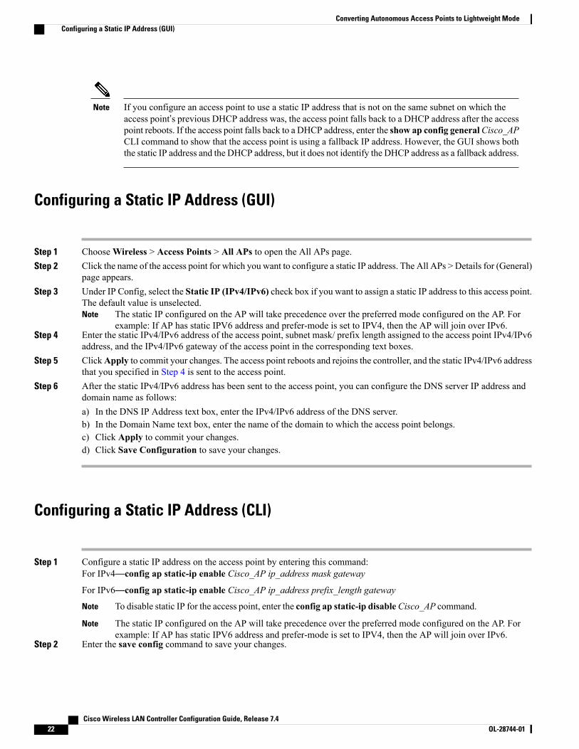
If you configure an access point to use a static IP address that is not on the same subnet on which theaccess point’s previous DHCP address was, the access point falls back to a DHCP address after the accesspoint reboots. If the access point falls back to a DHCP address, enter the show ap config generalCisco_APCLI command to show that the access point is using a fallback IP address. However, the GUI shows boththe static IP address and the DHCP address, but it does not identify the DHCP address as a fallback address.
Note
Configuring a Static IP Address (GUI)
Step 1 ChooseWireless > Access Points > All APs to open the All APs page.Step 2 Click the name of the access point for which you want to configure a static IP address. The All APs > Details for (General)
page appears.Step 3 Under IP Config, select the Static IP (IPv4/IPv6) check box if you want to assign a static IP address to this access point.
The default value is unselected.The static IP configured on the AP will take precedence over the preferred mode configured on the AP. Forexample: If AP has static IPV6 address and prefer-mode is set to IPV4, then the AP will join over IPv6.
Note
Step 4 Enter the static IPv4/IPv6 address of the access point, subnet mask/ prefix length assigned to the access point IPv4/IPv6address, and the IPv4/IPv6 gateway of the access point in the corresponding text boxes.
Step 5 ClickApply to commit your changes. The access point reboots and rejoins the controller, and the static IPv4/IPv6 addressthat you specified in Step 4 is sent to the access point.
Step 6 After the static IPv4/IPv6 address has been sent to the access point, you can configure the DNS server IP address anddomain name as follows:a) In the DNS IP Address text box, enter the IPv4/IPv6 address of the DNS server.b) In the Domain Name text box, enter the name of the domain to which the access point belongs.c) Click Apply to commit your changes.d) Click Save Configuration to save your changes.
Configuring a Static IP Address (CLI)
Step 1 Configure a static IP address on the access point by entering this command:For IPv4—config ap static-ip enable Cisco_AP ip_address mask gateway
For IPv6—config ap static-ip enable Cisco_AP ip_address prefix_length gateway
To disable static IP for the access point, enter the config ap static-ip disableCisco_AP command.Note
The static IP configured on the AP will take precedence over the preferred mode configured on the AP. Forexample: If AP has static IPV6 address and prefer-mode is set to IPV4, then the AP will join over IPv6.
Note
Step 2 Enter the save config command to save your changes.
Cisco Wireless LAN Controller Configuration Guide, Release 7.422 OL-28744-01
Converting Autonomous Access Points to Lightweight ModeConfiguring a Static IP Address (GUI)
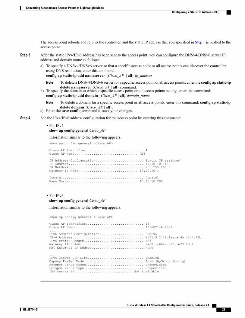
The access point reboots and rejoins the controller, and the static IP address that you specified in Step 1 is pushed to theaccess point.
Step 3 After the static IPv4/IPv6 address has been sent to the access point, you can configure the DNSv4/DNSv6 server IPaddress and domain name as follows:a) To specify a DNSv4/DNSv6 server so that a specific access point or all access points can discover the controller
using DNS resolution, enter this command:config ap static-ip add nameserver {Cisco_AP | all} ip_address
To delete a DNSv4/DNSv6 server for a specific access point or all access points, enter the config ap static-ipdelete nameserver {Cisco_AP | all} command.
Note
b) To specify the domain to which a specific access point or all access points belong, enter this command:config ap static-ip add domain {Cisco_AP | all} domain_name
To delete a domain for a specific access point or all access points, enter this command: config ap static-ipdelete domain {Cisco_AP | all}.
Note
c) Enter the save config command to save your changes.
Step 4 See the IPv4/IPv6 address configuration for the access point by entering this command:
• For IPv4:show ap config general Cisco_AP
Information similar to the following appears:show ap config general <Cisco_AP>
Cisco AP Identifier.............................. 4Cisco AP Name................................. AP6...IP Address Configuration......................... Static IP assignedIP Address....................................... 10.10.10.118IP NetMask....................................... 255.255.255.0Gateway IP Addr............................... 10.10.10.1
Domain........................................... Domain1Name Server................................... 10.10.10.205...
• For IPv6:show ap config general Cisco_AP
Information similar to the following appears:
show ap config general <Cisco_AP>
Cisco AP Identifier.............................. 16Cisco AP Name.................................... AP2602I-A-K9-1...IPv6 Address Configuration....................... DHCPv6IPv6 Address..................................... 2001:9:2:16:1ae:a1da:c2c7:44bIPv6 Prefix Length............................... 128Gateway IPv6 Addr................................ fe80::c60a:cbff:fe79:53c4NAT External IP Address.......................... None
...IPv6 Capwap UDP Lite............................. EnabledCapwap Prefer Mode............................... Ipv6 (ApGroup Config)Hotspot Venue Group.............................. UnspecifiedHotspot Venue Type............................... UnspecifiedDNS server IP ............................. Not Available
Cisco Wireless LAN Controller Configuration Guide, Release 7.4 OL-28744-01 23
Converting Autonomous Access Points to Lightweight ModeConfiguring a Static IP Address (CLI)

Supporting Oversized Access Point ImagesController software release 5.0 or later releases allow you to upgrade to an oversized access point image byautomatically deleting the recovery image to create sufficient space.
The recovery image provides a backup image that can be used if an access point power-cycles during an imageupgrade. The best way to avoid the need for access point recovery is to prevent an access point frompower-cycling during a system upgrade. If a power-cycle occurs during an upgrade to an oversized accesspoint image, you can recover the access point using the TFTP recovery procedure.
Recovering the Access Point—Using the TFTP Recovery Procedure
Step 1 Download the required recovery image from Cisco.com (for example, ap3g2-rcvk9w8-tar.152-4.JB6.tar for 2700 or3700 APs) and install it in the root directory of your TFTP server.
Step 2 Connect the TFTP server to the same subnet as the target access point and power-cycle the access point. The access pointboots from the TFTP image and then joins the controller to download the oversized access point image and completethe upgrade procedure.
Step 3 After the access point has been recovered, you may remove the TFTP server.
Cisco Wireless LAN Controller Configuration Guide, Release 7.424 OL-28744-01
Converting Autonomous Access Points to Lightweight ModeSupporting Oversized Access Point Images