conversion of magnetic energy in the magnetic reconnection...
TRANSCRIPT

ARTICLE
Received 5 May 2014 | Accepted 23 Jul 2014 | Published 10 Sep 2014
Conversion of magnetic energy in the magneticreconnection layer of a laboratory plasmaMasaaki Yamada1, Jongsoo Yoo1, Jonathan Jara-Almonte1, Hantao Ji1, Russell M. Kulsrud1 & Clayton E. Myers1
Magnetic reconnection, in which magnetic field lines break and reconnect to change their
topology, occurs throughout the universe. The essential feature of reconnection is that it
energizes plasma particles by converting magnetic energy. Despite the long history of
reconnection research, how this energy conversion occurs remains a major unresolved
problem in plasma physics. Here we report that the energy conversion in a laboratory
reconnection layer occurs in a much larger region than previously considered. The
mechanisms for energizing plasma particles in the reconnection layer are identified, and a
quantitative inventory of the converted energy is presented for the first time in a well-defined
reconnection layer; 50% of the magnetic energy is converted to particle energy, 2/3 of which
transferred to ions and 1/3 to electrons. Our results are compared with simulations and space
measurements, for a key step towards resolving one of the most important problems in
plasma physics.
DOI: 10.1038/ncomms5774
1 Center for Magnetic Self-organization, Princeton Plasma Physics Laboratory, Princeton University, Princeton, New Jersey 08544, USA. Correspondence andrequests for materials should be addressed to M.Y. (email: [email protected]).
NATURE COMMUNICATIONS | 5:4774 | DOI: 10.1038/ncomms5774 | www.nature.com/naturecommunications 1
& 2014 Macmillan Publishers Limited. All rights reserved.

Magnetic reconnection, the breaking and topologicalrearrangement of magnetic field lines in plasma, occurseverywhere in the universe, in solar flares, the Earth’s
magnetosphere, star formation and laboratory fusion plasmas1–4.The most important feature of magnetic reconnection is thatsignificant acceleration and heating of plasma particles occurs atthe expense of magnetic energy. An example of this efficientenergy conversion is the observation of large amounts of high-energy electrons associated with the reconnection of magneticfield lines in solar flares5. In the reconnection region of theEarth’s magnetosphere and the solar wind, convective outflowshave been documented by in situ satellite measurements. Despitethese advances, the exact physical mechanisms for bulk plasmaheating, particle acceleration and energy flow channels remainunresolved. This paper addresses the key unresolved question:how is magnetic energy converted to plasma kinetic energyduring reconnection? Furthermore, the conversion of magneticenergy is quantitatively evaluated for the first time in a laboratoryreconnection layer by assessing the overall energy inventory in awell-defined boundary.
In the classical Sweet–Parker model1, which is based on thecollision-dominated resistive magneto-hydrodynamics (MHD),the energy dissipation rate during reconnection is small(B(B2/2m0)VA/LS(1/2)) due to the slow reconnection rate; VA isthe Alfven velocity and S (441) is the Lundquist number2–4.Observations in nearly collision-free space and laboratoryplasmas show, however, that this prediction is not realized3,4.In the collisionless magnetic reconnection layer, electrons andions move quite differently from each other due to two-fluiddynamics3,4,6,7; furthermore, differential motion between themagnetized electrons and the unmagnetized ions generates strongHall currents in the reconnection layer. In the two-fluidformulation, the Ohm’s law of MHD should be replaced by ageneralized Ohm’s law to describe the force balance of an electronflow, namely,
E ¼ Zjþ je�B�r � Pe
ene� me
edVe
dtð1Þ
Here the conventional notations are used with E being theelectric field and B reconnecting magnetic field, Ve the electronflow velocity, j the current density, je is the electron currentdensity and Pe the spatially dependent electron pressure tensor3.A large out-of-plane electric field caused by the Hall currents atthe reconnection layer (jHall�B) causes an increase in thereconnection rate3,4,6,7 by inducing rapid movement of thereconnecting field lines. This explains why the reconnection ratein collisionless plasmas is much faster than the classical Sweet–Parker rate.
In spite of recent progress, a major question remainsunresolved: how is energy transferred from the magnetic fieldto plasma particles? A simple two-dimensional (2D) numericalsimulation would expect that field line breaking and energydissipation is localized in the small electron diffusion regionwhose width is on the order of the electron skin depth (de¼ c/ope,where c is the speed of light and ope is the electron plasmafrequency). However, significant acceleration and heating of bothions and electrons have been observed and analyzed in a wideregion of the actual reconnection layer8–15 of laboratory andspace plasmas. Although quantitative studies of energy flow havebeen recently reported based on multiple satellite data12,15, to ourknowledge, a comprehensive analysis of energy inventory overa well-defined reconnection layer has not been made. Aquantitative analysis of the energy conversion rate together withthe identification of heating mechanisms and location wouldprovide key insights into the energy conversion processes.
Here we report that the energy conversion in a laboratoryreconnection layer occurs in a much larger region than previouslyconsidered. We observe that electron heating occurs outside theelectron diffusion region and that ion acceleration and heatingdominate in a wide region of the exhaust of the reconnectionlayer, which ranges beyond several ion skin depths. Themechanisms for energizing plasma particles in the magneticreconnection layer are identified, and a quantitative inventory ofthe converted energy is presented for the first time in a well-defined reconnection layer. The study concludes that B50% ofthe magnetic energy is converted to particle energy, two-thirdsof which transferred to ions and one-third to electrons. Ourresults are compared with numerical simulations and spacemeasurements.
ResultsExperimental apparatus. We use the MRX facility16 toexperimentally study the conversion of magnetic energy toparticle energy in a nearly collision-free reconnection layer.Figure 1a shows a schematic of the MRX apparatus, wherein twooppositely directed field lines merge and reconnect. Experimentsare carried out in a setup in which two toroidal plasmas withannular cross-section are formed around two flux cores as shownin Fig. 1a. As we induce magnetic reconnection by drivingoppositely directed field lines towards the X-point (B¼ 0 at thecentre of the layer) using pulsed flux core currents, ions andelectrons also flow into the reconnection layer. The ions becomedemagnetized at a distance of the ion skin depth (di¼ c/opi,where opi is the ion plasma frequency) from the X-point wherethey enter the so-called ion diffusion region, and they changetheir trajectories and are diverted into the reconnection exhaustas seen Fig. 1b. The electrons, on the other hand, remainmagnetized through the ion diffusion region and continue to flowtowards the X-point. They become demagnetized only whenthey reach the much narrower electron diffusion region(B10deB1 cm in MRX) as seen in Fig. 1b. Electron currentsflow dominantly in the out-of-plane direction (Y) near the centre(X-point) as shown in Fig.1c. For standard conditions, theelectron density and temperature are, neB(2–6)� 1013 cm� 3,Te¼ 5–15 eV, for B¼ 0.1–0.3 kG, S4500; the electrons are well-magnetized (gyro-radius, reB1 mmooplasma size, L) while theions are not. The mean free path for electron–ion Coulombcollisions, lmfp, is in the range of 6–20 cm that is larger than thelayer thickness, and as a result, the reconnection dynamics arenearly collision-free and dominated by two fluid and kineticeffects3,4. In this plasma, the energy exchange between electronsand ions is small since the characteristic energy transfer time islonger than the electron confinement time. The ion skin depth is6–8 cm and the electron skin depth is typically 1 mm. We use(R, Y and Z) coordinates where BZ is the reconnecting fieldcomponent and Y is the out-of-plane direction. Helium plasmaswith a fill pressure of 4.5 mTorr are used for this study to facilitateion temperature measurements. No external guide field is appliedfor this study. The plasma beta in the inflow region is about 0.1.Our measurements are carried out in a steady state reconnectionphase which last 20–30ms, significantly longer than the Alfventime (B1 ms).
We document comprehensively the dynamics of plasmaparticles and determine the mechanisms for energy conversionin the reconnection layer using extensive in situ diagnostics. Themain diagnostic is a 2D magnetic probe array that measures theevolution of all three components of the magnetic field at 4200locations in the reconnection plane. The array consists of sevenprobes with a separation of 3 cm along Z. Each probe has35 miniature pickup coils with a maximum radial (R) resolution
ARTICLE NATURE COMMUNICATIONS | DOI: 10.1038/ncomms5774
2 NATURE COMMUNICATIONS | 5:4774 | DOI: 10.1038/ncomms5774 | www.nature.com/naturecommunications
& 2014 Macmillan Publishers Limited. All rights reserved.
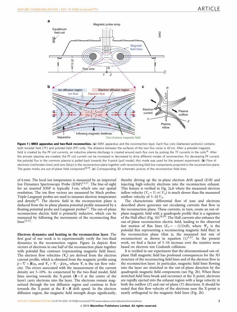
of 6 mm. The local ion temperature is measured by an improvedIon Dynamics Spectroscopy Probe (IDSP)11,17. The line-of-sightfor an inserted IDSP is typically 3 cm, which sets our spatialresolution. The ion flow vectors are measured by Mach probes.Triple Langmuir probes are used to measure electron temperatureand density16. The electric field in the reconnection plane isdeduced from the in-plane plasma potential profile measured by afloating potential probe and Langmuir probes11. The out-of-planereconnection electric field is primarily inductive, which can bemeasured by following the movements of the reconnecting fluxlines11,13.
Electron dynamics and heating in the reconnection layer. Thefirst goal of our work is to experimentally verify the two-fluiddynamics in the reconnection region. Figure 2a depicts flowvectors of electrons in one half of the reconnection plane togetherwith poloidal flux contours (representing magnetic field lines).The electron flow velocities (Ve) are derived from the electroncurrent profile, which is obtained from the magnetic profile usingj¼r�B/m0 and Ve¼Vi� j/ene, where Vi is the ion flow velo-city. The errors associated with the measurement of the currentdensity are 5–10%. As conjectured by the two-fluid model, fieldlines moving towards the X-point (B¼ 0 at the centre of thelayer) carry electrons into the layer. The electrons remain mag-netized through the ion diffusion region and continue to flowtowards the X-point at the E�B drift speed. In the electrondiffusion region, the magnetic field strength drops significantly,
thereby driving up the in-plane electron drift speed (E/B) andinjecting high-velocity electrons into the reconnection exhaust.This feature is verified in Fig. 2a,b where the measured electroninflow velocity (VeBViooVA) is much slower than the measuredoutflow velocity of 5–10 VA.
The characteristic differential flow of ions and electronsdescribed above generates net circulating currents that flow inthe reconnection plane. These currents, in turn, create an out-of-plane magnetic field with a quadrupole profile that is a signatureof the Hall effect (Fig. 1b)18,19. The Hall currents also enhance theout-of-plane reconnection electric field, leading to the observedfast motion of flux lines (EY¼ � (1/2pR), where Cp is thepoloidal flux representing a reconnecting magnetic field flux) inthe reconnection plane (that is, the measured fast rate ofreconnection) as shown in equation (1)3,13. In the presentwork, we find a factor of 5–10 increase over the resistive termbased on electron–ion Coulomb collisions.
It is verified in our experiment that the aforementioned out-of-plane Hall magnetic field has profound consequences for the 3Dstructure of the reconnecting field lines and of the electron flow inthe reconnection layer. In particular, magnetic field lines flowinginto the layer are stretched in the out-of-plane direction by thequadrupole magnetic field components (see Fig. 2b). When thesestretched field lines break and reconnect at the X-point, electronsare rapidly ejected into the exhaust region with a large velocity inboth the outflow (Z) and out-of-plane (Y) directions. It should benoted that this flow velocity of the electrons near the X-point isnearly orthogonal to the magnetic field lines (Fig. 2b).
Equilibriumfield coil
Magnetic probe array
Magneticfield lines
Flux core
Ion diffusion region Electron diffusion region
Inflowing magnetic fieldlines
Plasmainflow
Plasmaoutflow
Electroncurrent
R
YZ
Separatrix Out-of-plane magnetic field
Ion flow Electron flow
37.5 cm
R
ZY
Figure 1 | MRX apparatus and two-fluid reconnection. (a) MRX apparatus and the reconnection layer. Each flux core (darkened sections) contains
both toroidal field (TF) and poloidal field (PF) coils. The distance between the surfaces of the two flux cores is 42 cm. After a poloidal magnetic
field is created by the PF coil currents, an inductive plasma discharge is created around each flux core by pulsing the TF currents in the coils16. After
the annular plasmas are created, the PF coil current can be increased or decreased to drive different modes of reconnection. For decreasing PF current,
the poloidal flux in the common plasma is pulled back towards the X-point (pull mode); this mode was used for the present experiment. (b) Flow of
electrons (red broken lines) and ions (blue) in the reconnection plane together with reconnecting field line components projected in the reconnection plane.
The green marks are out-of-plane field component18,19. (c) Corresponding 3D schematic picture of the reconnection field lines.
NATURE COMMUNICATIONS | DOI: 10.1038/ncomms5774 ARTICLE
NATURE COMMUNICATIONS | 5:4774 | DOI: 10.1038/ncomms5774 | www.nature.com/naturecommunications 3
& 2014 Macmillan Publishers Limited. All rights reserved.

A notable rise of electron temperature (up to 50%) is measuredover an area that is much wider than the electron diffusion regionas seen Fig 2c. The energy deposition rate on electrons, je �E, isconcentrated near the X-point as seen in Fig. 2d, but in a widerregion (B10de) than predicted by 2D numerical simulations20,21.The measured 2D electron temperature profile in Fig. 2c showsthat the electron heating spreads along the magnetic field lineslikely due to strong parallel heat conduction. Consequently, theelectron temperature in the exhaust region is higher than in theinflow region. This observation agrees with the recent spaceobservation of bulk electron heating in the reconnection exhaustregion at the dayside magnetopause22. We note that Ohmicdissipation based on classical resistivity accounts for o20% of therequired heating power23. Magnetic and electrostatic fluctuationsin the lower hybrid frequency range (1–15 MHz) areobserved23–25 near the X-point and throughout the downstreamregion, and are attributed to the observed strong electron heating,although a quantitative relationship is yet to be determined.While the magnitude of the magnetic field decreases towards theX-point, the total electron kinetic and thermal energy withrespect to the magnetic energy increases substantially. Theelectron beta [BneTe/(B0
2/2m0)] is expected to significantlyexceed unity inside the observed broad electron diffusionregion, breaking the condition of a magnetically confined stateas is clearly seen in Fig. 2b.
Ion acceleration and heating in the reconnection layer. It isfound that the flows of magnetized electrons, which cause theHall effects, also produce a strong electric field in the
reconnection plane that is strongest across the separatrices, whichseparates the incoming field line region from the exhaust ofreconnected field lines as shown in Fig. 3a. It is experimentallyverified in MRX that a saddle-shaped electric potential profile isformed in the reconnection plane to balance the Lorentz force onthe electron flows11. A strong in-plane electric field is generatednear the separatrices with a wider and deeper potential welldownstream. The MRX potential data is consistent withmeasurements from the CLUSTER spacecraft8, which showed anarrow potential well near the X-point with a half width in therange of 60–100 km (3–5de), and a deeper and wider well towardsthe exhaust region. The in-plane electric field (or potentialgradient) is largely perpendicular to the local magnetic field linesand is strongest near the separatrices20,26. The electric potential isseen to be nearly constant along a poloidal flux contour (ormagnetic field line) as seen in Fig. 3a in the half reconnectionplane. In this figure, we note that a large electric field across theseparatrices extends to a significantly larger area of thereconnection layer (L44di), than the region in which field linebreaking and reconnection occur. A typical magnitude of the in-plane electric field, Esep is B700 V m� 1, which is much largerthan the reconnection electric field in the out-of-plane direction,ErecB200 V m� 1.
We observe electrostatic acceleration of ions near theseparatrices due to the strong electric field mentioned above,whose spatial scale is B2 cm, smaller than the ion gyro-radius ofB8 cm. Figure 3a also shows 2D profile of ion flow vectorsmeasured by Mach probes, along with colour contours of theplasma potential, Fp. We observe clearly that the ion flowschange their direction at the separatrices and are accelerated in
R (
cm)
Z (cm)
Magnetic field lines and electronflow vectors
0 5 10 15
32
34
36
38
40
42
44
R (
cm)
32
34
36
38
40
42
R (
cm)
32
34
36
38
40
42
je ·E profile44
0 5 10 15
–530
35
40
45
05
Z (cm)
2D electron temperature profile
0 5 10 1015Z (cm)
0 5 156
7
8
9
10
11
12
0
50
100
150
Z (cm)3D View of Fig. a
R (cm)
Y (cm)
Te (eV) (W cm–3)
10
Figure 2 | Electron dynamics and heating. (a,b) Measured electron flow vectors and measured field lines in the half reconnection plane and its
perspective view in 3D geometry. While ions and electrons move together with the field lines before entering the ion diffusion region, electrons move
much faster as they approach the X-point region. Vector length (1 cm in the figure scale) stands for 4.5� 106 cm s� 1. (c,d) Strong electron temperature rise
is observed in a wide area of the exhaust region, while the energy deposition to electrons, je � E, is concentrated near the X-point as seen in d: strong parallel
heat conduction is considered to be the cause of the high Te at the exhaust region. The ion skin depth, di is 8 cm and the electron skin depth, de is 1 mm,
typically. In this nearly collision-free condition (lmfp44de), two-fluid dynamics dominate.
ARTICLE NATURE COMMUNICATIONS | DOI: 10.1038/ncomms5774
4 NATURE COMMUNICATIONS | 5:4774 | DOI: 10.1038/ncomms5774 | www.nature.com/naturecommunications
& 2014 Macmillan Publishers Limited. All rights reserved.

both the Z and the R directions. The energy deposition rate onions, ji .E, is concentrated near the separatrices in the exhaustregion as seen in Fig. 3b. Figure 3d depicts the ion velocitydistribution function versus ViZ as measured by the IDSP probesat the three locations specified in Fig. 3a. In this measurement, theIDSP spectra are converted to the local velocity distributions ofions versus ViZ as described in the Methods section. ShiftedMaxwellian distributions are observed at typical positions (R, Z)as shown in Fig. 3d. Notable heating is observed as the ions flowout into the exhaust from the X-region, as demonstrated inFig. 3d.
The cause of this anomalously rapid slowdown of ions,together with ion heating, is considered to be the remagnetizationof the exiting ions. As the R component of reconnected magneticfield becomes stronger in the downstream region, the iontrajectories (black thick line in Fig. 3c) are significantly affectedby the magnetic field of the exhaust and thus ions areremagnetized.
A 2D fully kinetic simulation has been carried out to verifythese remagnetization mechanisms and understand how ions areheated downstream (Fig. 3c). In these simulations, realistic MRXglobal boundary conditions are used in the particle-in-cell (PIC)code VPIC (vectorized particle-in-cell). VPIC is a first-principle,fully kinetic, electromagnetic PIC code that is optimized for large-
scale simulations27,28. The system size is about 15� 30di with1,200� 2,400 cells and 350 particles per cell. The mass ratio in thesimulations is mi/me¼ 400, ope/oce¼ 1, and the initial electronthermal velocity is 0.125c with Ti¼Te. Key physical parametersfor the ions such as the ion skin depth and the mean free path arematched to experimentally measured parameters. In thesimulations, Coulomb collisions28 are included to study effectsof collisions on the ion dynamics.
We obtain good agreement between the observed iontemperature profile and numerical simulation results only withrealistic collision frequencies. This shows that ions are almostfully thermalized in the exhaust with a higher temperature thanthe upstream value. As illustrated with the dashed line in Fig. 3c,the Coulomb collisions enhance the downstream ion thermaliza-tion process by scattering ions. In the completely collisionlesssimulation, on the other hand, the ion distribution is differentfrom Maxwellian. Ion velocity profiles at three differentlocations—upstream, at the separatrix and downstream—fromour PIC simulations with collisions (Fig. 3e) are in reasonablygood agreement with experimentally measured profiles (Fig. 3d).
Energy inventory in the two-fluid reconnection layer. When areconnection electric field is uniformly applied over a wide region
Field lines, potential profile, andion flow vectors
42
40
38
34
32
0 5 10 15
10
20
30
40
50
�p (V )
Z (cm)
R (
cm)
36
(1)X
(2)X
(3)X
ji·E profile
42
40
38
34
32
0 5 10 150
5
10
15
20
25
30(W cm–3)
Z (cm)
R (
cm)
36
X(1)
X(2)
X(3)
Ion trajectories
With collisions
W/O collisions
2
1.5
0.5
–0.5
–1
–1.5
–1 0 1 2 3Z (di)
0
1
X (
di)
Measured iondistribution
0.6
0.5
0.4
0.3
0.2
0.1
0–4 –2
v iz/vth0
0 2 4
f(v i
z)
(1)
(2)
(3)
Simulated iondistribution
viz/vth0
–4 –2 0 2 4
0.6
0.5
0.4
f(v i
z)
0.3
0.2
0.1
0
(1)(2)
(3)
a
c d e
b
Figure 3 | Potential profile and ion dynamics. (a) Saddle-shaped electrostatic potential (Fp) profile deduced from Langmuir probe measurements,
together with ion flow vectors (length represents velocity) measured by Mach probes. The black lines stand for the contours of the poloidal magnetic flux,
Cp. (b) the energy deposition on ions, ji.E, concentrated near the separatrices in the exhaust region. (c) Sample ion trajectories in a VPIC simulated
reconnection plane with (thick solid line) and without (thick dashed line) collisions. The ion trajectories are significantly affected by the magnetic field in
the downstream region through remagnetization. With collisions, ions are almost fully thermalized with a higher temperature than the initial value.
(d) Normalized ion velocity (ViZ) distribution function at three different locations specified with crosses in a. The asterisks are values deduced from the
measured He II 4686 Å spectra, while the solid lines stand for fitting to the Maxwellian function. Here the ion velocity is normalized by vth0, which is
the ion thermal velocity in the inflow region. (e) Corresponding data from the numerical simulations are shown. The three locations are marked with
crosses in c. Across the separatrix, ions are accelerated towards the outflow region. The results indicate that ion thermalization is due to remagnetization
with the effects of collisions in the downstream region. We note that the ion and electron dynamics are primarily dictated by (collision free) two-fluid
physics even if some energy loss mechanisms are influenced by collisions.
NATURE COMMUNICATIONS | DOI: 10.1038/ncomms5774 ARTICLE
NATURE COMMUNICATIONS | 5:4774 | DOI: 10.1038/ncomms5774 | www.nature.com/naturecommunications 5
& 2014 Macmillan Publishers Limited. All rights reserved.

in which opposite magnetic field lines meet, such as shown inFig. 1, electrons with high mobility respond to this field bycreating a highly stressed region of magnetic and electric fieldscaused by Hall effects. This reconnection process partitionsinflowing field lines from the reconnected ones by separatrices,across which a notable potential drop (strong electric field)occurs, accumulating large free energy. While electrons are heatedat the centre of the reconnection layer, ions are accelerated acrossthe separatrices by the strong electric field and heated throughremagnetization by the magnetic field. This electric field structureextends to a very broad region, much wider than the ion skindepth. Now, two important questions are raised: (1) How muchenergy is transported to particles; and (2) How is that energypartitioned?
Using an energy transport equation analogous to that adoptedby Birn and Hesse29, we evaluate how much of the magneticenergy is converted to the kinetic energy of electrons and ions byassessing the energy inventory of the reconnection layer.
@
@tB2
2m0þXs¼e;i
32
nsTsþrs
2
� �" #
þr SþXs¼e;i
52
nsTsVsþrs
2V2
s Vs
� �" #¼Xs¼e;i
Ls;
ð2Þ
where Ls is the loss term for each species including thermalconduction, radiation and ion energy loss to neutrals. The energyinventory is calculated by monitoring the flow of magneticenergy, plasma enthalpy and bulk flow energy simultaneously,while measuring the incoming and outgoing electromagneticPoynting flux (S), enthalpy flux and bulk flow flux (kinetic energyflux) at a fixed boundary. The boundary of the volume of theplasma, Gb, is given by 31.5rRr43.5 cm and 0rZr15 cm(Fig. 1), in which all key local plasma parameters are measuredwithin 10–15% error bars, assuming symmetry with respect to themajor axis of the MRX plasma. Figure 4 presents a measuredenergy inventory, which flows from the magnetic field to plasmaparticles.
It is important to include the components of the Hall magneticfields in both the incoming and exhaust regions to accuratelytrack the Poynting fluxes. As was done in the study by Birn andHesse29, isotropic pressure is assumed in this calculation, which isjustified in our plasma where anisotropy was only observed in asmall region near the X-point. The magnetic energy outflow rateis divided into two components, the conventional MHD part andthe Hall-field part associated with the out-of-plane magnetic fieldand the electrostatic in-plane field. Since the vacuum componentof the magnetic field is slowly decreasing during the quasi-steadyreconnection period, the first term of the LHS of equation (2) isnot negligible. The energy conversion rate to electrons and ions isindependently calculated by integrating js .E over the volume Gb.As seen in the Fig. 4, about half of the incoming magnetic energyis converted to particle energy, of which 1/3 goes to electrons(15% of magnetic energy) and 2/3 to ions (25–30% of magneticenergy). In our 2.5D simulation study using the VPIC code, asimilar result is obtained. The energy deposited on the electronsbecomes thermal energy and is transferred to the exhaust by heatconduction, the energy deposited on the ions is converted tothermal and flow energy with substantial conduction andconvection losses. The conversion of magnetic energy in theexperiment occurs across a broad region, much larger thanconsidered before.
DiscussionOur quantitative measurements of the acceleration and heating ofboth electrons and ions demonstrate that more than half of theincoming magnetic energy is converted to particle energy at aremarkably fast speed (B0.2VA) in the reconnection layer. Thisspeed is significantly larger than the value calculated by MHD,0.03VA for S¼ 900. This difference would become notably largerfor space astrophysical plasmas with much larger S. A questionarises as to whether the present results should be applied tomagnetic reconnection phenomena in space, astrophysical, orfusion plasmas. Recently, in a reconnection region of effectivelysimilar size in the Earth’s magnetotail, the energy partition wascarefully measured during multiple passages of the Cluster
Magnetic energy inflow rate1.9±0.2 MW
Rate of magneticenergy decrease–0.19±0.02 MW
Energy depositionrate to ions
0.71±0.15 MW
Change of flowenergy
0.14±0.06 MW
Change ofthermal energy0.27±0.1 MW
Energy loss rate(conduction,
neutrals)< 0.35 MW
Energy depositionrate to electrons0.35±0.06 MW
Change of flowenergy
~0
Change ofthermal energy0.26±0.1 MW
Energy loss rate(conduction,
radiation)0.15±0.08 MW
Magnetic energyoutflow rate
0.94±0.09 MW
MHD component
0.43±0.04 MW
Hall-fieldcomponent
0.51±0.05 MW
Figure 4 | Energy flow chart in the MRX reconnection layer. All quantities are shown as rate of energy flow with respect to (WM,in¼ 1.9 MW).
The outgoing Poynting flux is sizable in MRX, where two-fluid reconnection occurs because of outgoing energy associated with the Hall-field components.
Our quantitative measurements show that half of the incoming magnetic energy is converted to particle energy at a remarkably fast speed,
B0.2(B2/2m0)VA in comparison with the rate calculated by MHD, (B2/2m0)VA/S(1/2)¼0.03(B2/2m0)VA; S¼900. This difference would become
significantly larger for space astrophysical plasmas with much larger S.
ARTICLE NATURE COMMUNICATIONS | DOI: 10.1038/ncomms5774
6 NATURE COMMUNICATIONS | 5:4774 | DOI: 10.1038/ncomms5774 | www.nature.com/naturecommunications
& 2014 Macmillan Publishers Limited. All rights reserved.

satellites12. Although the moving X-line in these measurementsmade it difficult to identify the exact location of the magnetotail-reconnection region, the half length of the tail reconnection layer(L) was estimated to be 2,000–4,000 km namely 3–6di. Thenormalized scale length of this measurement is very similar to ourcases, LB3di. Reconnection in the magnetotail is driven byexternal force, that is, the solar wind, and the boundaryconditions are very similar to the MRX setup. The observedenergy partition12 is notably consistent with the present MRXdata, namely, 450% of the magnetic energy flux is converted tothe particle energy flux, which is dominated by the ion enthalpyflux, with smaller contributions from both the electron enthalpyand heat flux. Also this comparison has implications for itsscaling with Lundquist number. When we compare our resultsfrom plasmas of So1,000 with that of the magnetosphere wherethe Lundquist number is very large (4108), we find that theenergy flow pattern is very similar, that is, the energizationcharacteristics do not strongly depend on the Lundquist number.This is consistent with the characteristics of the two-fluid plasmaphysics, where the classical resistivity based on electron–ioncollisions does not play a major role.
Finally, in reversed field pinch fusion plasmas where magneticreconnection plays a key role in self-organized plasma formationand sustainment, it has been recently reported that a similarportion of magnetic energy (25–30%) is converted to ion thermalenergy10. Is there a fundamental physics principle to explain theseobservations from driven reconnection layers despite somedifferences in the boundary conditions? We believe the presentresults represent a key step towards resolving one of the mostimportant problems of plasma physics, how magnetic energy istransferred to plasma particles in the reconnection layer.
MethodsAdditional details on diagnostics. Triple Langmuir probes11 are used to measurethe electron temperature and density. The density measurements are calibratedby data from a CO2 interferometer. A radial profile of the floating potential isobtained from a 17-tip floating potential probe with maximum resolution of 7 mm.Local ion temperature is measured by IDSPs (ref. 10), which obtain the spectrum ofthe He II 4686 Å line, which is subsequently fitted to a sum of 13 Gaussianfunctions to take fine structure effects into account30; without considering finestructure, the ion temperature is overestimated by 15–25%. The time and spatialresolution of the IDSPs are 5.6 ms and 3–4 cm, respectively. Mach probes are usedto measure the ion flow velocity due to its better spatial and temporal resolutions.The data from the Mach probe are calibrated by spectroscopic measurements fromthe IDSPs.
Data acquisition and error analysis. To select the final data set, more than 4,200discharges were scrutinized based on the reproducibility of the data from the 2Dmagnetic probe array and a reference Langmuir probe. The main criteria are thelocation of the X-point, the total plasma current and the density and temperaturemeasured by a reference Langmuir probe. The data values at each measurementpoint are determined by averaging over 7–15 discharges. The error bars for eachmeasurement are chosen between the standard deviation of each data set and theuncertainty in measurements, whichever is larger. Typical errors in magnetic fieldmeasurements are o10%, while those in electrostatic measurements are 15%. Theuncertainty in the ion temperature measurements mostly comes from the fittingprocess and is typically B15%.
Calculation of the energy inventory. The energy inventory is calculated byintegrating each term in equation (2) over the volume Gb. The magnetic energyinflow rate is estimated by
WS;in ¼ZGb
d3xr � Sin ð3Þ
where Sin¼ (EYBZ/m0)eR is the incoming Poynting flux. Here eR is the unit vectoralong the R direction. The outgoing magnetic energy is obtained by integrating thedivergence of the outgoing Poynting flux. The outgoing Poynting flux is dividedinto the MHD component, SMHD¼ � (EYBR/m0)eZ and theHall-field component, SHall¼ (ERBY/m0)eZ� (EZBY/m0)eR. The integration of thefirst term of the right-hand side of equation (2) indicates the decrease of themagnetic energy per unit time inside vB. Total energy converted to each species
per unit time is separately computed by
WS ¼ZGb
d3x js � E ð4Þ
To obtain change in a specific form of energy, we grouped associated terms inequation (2). The flow energy change of species s is given by
DWKs ¼ZGb
d3x@
@trs
2V2
s
� �þr � rs
2V2
s V s
� �� �ð5Þ
The thermal energy change of species s is defined as
DWHs ¼ZGb
d3x@
@t32
nsTs
� �þr � 5
2nsTsV s
� �� �ð6Þ
We note that quantities in the inflow region are taken into account. We estimatethe energy loss rate of each species by considering the electron and ion heat flux,electron energy loss by impurity radiation and ion energy loss to neutrals bycharge-exchange collisions.
References1. Parker, E. N. Sweet’s mechanism for merging magnetic fields in conducting
fluids. J. Geophys. Res. 62, 509–520 (1957).2. Priest, E. & Forbes, T. Magnetic reconnection—MHD theory and applications
(Cambridge University Press, 2000).3. Yamada, M., Kulsrud, R. & Ji, H. Magnetic reconnection. Rev. Mod. Phys. 82,
603–664 (2010).4. Zweibel, E. G. & Yamada, M. Magnetic reconnection in astrophysical and
laboratory plasmas. Annu. Rev. Astron. Astrophys. 47, 291–332 (2009).5. Krucker, S. et al. Measurements of the coronal acceleration region of a solar
flare. Astrophys. J. 714, 1108–1119 (2010).6. Birn, J. et al. Geospace environmental modeling (GEM) magnetic reconnection
challenge. J. Geophys. Res. 106, 3715–3719 (2001).7. Sonnerup, B. U. O. Magnetic Field Reconnection. (eds Lanzerotti, L. T., Kennel,
C. F. & Parker, E. N.) Vol. 3 (North-Holland Publishing Co. 45–108, 1979).8. Wygant, J. R. et al. Cluster observations of an intense normal component of the
electric field at a thin reconnecting current sheet in the tail and its role in theshock-like acceleration of the ion fluid into the separatrix region. J. Geophys.Res. 110, A09206 (2005).
9. Drake, J. F. et al. Ion heating resulting from pickup in magnetic reconnectionexhausts. J. Geophys. Res. 114, A05111 (2009).
10. Fiksel, G. et al. Mass-dependent ion heating during magnetic reconnection in alaboratory plasma. Phys. Rev. Lett. 103, 145002 (2009).
11. Yoo, J. et al. Observation of ion acceleration and heating during collisionlessreconnection in a laboratory plasma. Phys. Rev. Lett. 110, 215007 (2013).
12. Eastwood, J. P. et al. Energy partition in magnetic reconnection in Earth’smagnetotail. Phys. Rev. Lett. 110, 225001 (2013).
13. Yamada, M. Progress in understanding magnetic reconnection in laboratoryand space astrophysical plasmas. Phys. Plasmas 14, 058102 (2007).
14. Egedal, J. et al. Evidence and theory for trapped electrons in guide fieldmagnetotail reconnection. J. Geophys. Res. 113, A12207 (2008).
15. Angelopoulos, V. et al. Electromagnetic energy conversion at reconnectionfronts. Science 341, 1478 (2013).
16. Yamada, M. et al. Study of driven magnetic reconnection in a laboratoryplasma. Phys. Plasmas 4, 1936–1944 (1997).
17. Fiksel, G., Hartog, D. J. D. & Fontana, P. W. An optical probe for localmeasurements of fast plasma ion dynamics. Rev. Sci. Instrum. 69, 2024–2026(1998).
18. Ren, Y. et al. Experimental verification of the Hall effect during magneticreconnection in a laboratory plasma. Phys. Rev. Lett. 95, 055003 (2005).
19. Yamada, M. et al. Experimental study of two-fluid effects on magneticreconnection in a laboratory plasma with variable collisionality. Phys. Plasmas13, 052119 (2006).
20. Pritchett, P. L. Onset of magnetic reconnection in the presence of a normalmagnetic field: realistic ion to electron mass ratio. J. Geophys. Res. 115, A10208(2010).
21. Ji, H. et al. New insights into dissipation in the electron layer during magneticreconnection. Geophys. Res. Lett. 35, L13106 (2008).
22. Phan, T. D. et al. Electron bulk heating in magnetic reconnection at Earth’smagnetopause: dependence on the inflow Alfven speed and magnetic shear.Geophys. Res. Lett. 40, 4475–4480 (2013).
23. Yoo, J. et al. Bulk ion acceleration and particle heating during magneticreconnection in a laboratory plasma. Phys. Plasmas 21, 055706 (2014).
24. Ji, H. et al. Electromagnetic fluctuations during fast reconnection in alaboratory plasma. Phys. Rev. Lett. 92, 115001 (2004).
25. Ren, Y., Yamada, M., Ji, H., Gerhardt, S. P. & Kulsrud, R. Identification of theelectron-diffusion region during magnetic reconnection in a laboratory plasma.Phys. Rev. Lett. 101, 085003 (2008).
NATURE COMMUNICATIONS | DOI: 10.1038/ncomms5774 ARTICLE
NATURE COMMUNICATIONS | 5:4774 | DOI: 10.1038/ncomms5774 | www.nature.com/naturecommunications 7
& 2014 Macmillan Publishers Limited. All rights reserved.

26. Karimabadi, H., Daughton, W. & Scudder, J. Multi-scale structure of theelectron diffusion regions. Geophys. Res. Lett. 34, L13104 (2007).
27. Bowers, K. J. et al. Ultrahigh performance three-dimensional electromagneticrelativistic kinetic plasma simulation. Phys. Plasmas 15, 055703 (2008).
28. Roytershteyn, V. et al. Driven magnetic reconnection near the Dreicer limit.Phys. Plasmas 17, 055706 (2010).
29. Birn, J. & Hesse, M. Energy release and conversion by reconnection in themagnetotail. Ann. Geophys. 23, 3365–3373 (2005).
30. Wiese, W. L. & Fuhr, J. R. Accurate atomic transition probabilities forhydrogen, helium, and lithium. J. Phys. Chem. Ref. Data 38, 565–719 (2009).
AcknowledgementsWe appreciate many inputs from W. Daughton for our VPIC simulation and usefuldiscussions with J. Eastwood on space observations. This work is supported bythe Department of Energy as well as the NSF-funded Center for MagneticSelf-Organization.
Author contributionsM.Y. carried out this research by collecting, analyzing and interpreting the data fromMRX, and coordinated the experimental results with results from space observation,numerical simulations and theory. J.Y. carried out experimental campaigns and keymeasurements reported here. He analyzed the data and generated the key figures used inthis manuscript. J.J.-A. assisted the experiments and carried out numerical simulationsusing the VPIC code. H.J., R.M.K., C.E.M. participated in this research by analyzing andinterpreting the data from MRX.
Additional informationCompeting financial interests: The authors declare no competing financial interests.
Reprints and permission information is available online at http://npg.nature.com/reprintsandpermissions/
How to cite this article: Yamada, M. et al. Conversion of magnetic energy in themagnetic reconnection layer of a laboratory plasma. Nat. Commun. 5:4774doi: 10.1038/ncomms5774 (2014).
ARTICLE NATURE COMMUNICATIONS | DOI: 10.1038/ncomms5774
8 NATURE COMMUNICATIONS | 5:4774 | DOI: 10.1038/ncomms5774 | www.nature.com/naturecommunications
& 2014 Macmillan Publishers Limited. All rights reserved.