controls instruction operation & maintenance iom v3 august 20… · operation & maintenance...
TRANSCRIPT
CONTROLS INSTRUCTION
OPERATION & MAINTENANCE
VPR Series VPRE Series
VPRC/P Series VPRX Series
IOM-C1-0814 Software Version 3
Part Number 474626

Valent Controls IOM 2 IOM-C1-0814 Part Number 474626
Table of Contents
Safety ................................................................................. 3
Control Interfaces ............................................................. 3
Using the LCD ................................................................... 4 Changing a Setpoint ..................................................... 5 Manually Overriding a Setpoint .................................... 5 Changing a Schedule ................................................... 6 Changing the IP Address .............................................. 7 Reviewing BACnet IP or MSTP Settings ...................... 7 Reviewing LonWorks Settings ...................................... 8 LCD Map ...................................................................... 9
Using the Universal Maintenance Tool (UMT) .............. 10 Installing the Software ................................................ 10 Configuring the IP Address for the PC ....................... 10 Logging on to the Controller ....................................... 13 Changing System Time and Date ............................... 14 Changing the IP Address ............................................ 14 Checking Unit Status .................................................. 15 Changing a Setpoint ................................................... 15 Changing the Fan Speed ............................................ 16 Manually Overriding a Setpoint .................................. 16 Changing a Schedule ................................................. 17 UMT Map .................................................................... 18
Using the Web User Interface (Web UI) ........................ 20 Connecting to the Network ......................................... 20 Configuring the IP Address for the PC ....................... 20 Logging On to the Web Interface ................................ 20 Changing a Setpoint ................................................... 20 Manually Overriding a Setpoint .................................. 21 Changing a Schedule ................................................. 22
Using BACnet Communications .................................... 23
Using LonTalk Communications ................................... 23
Input/Output Points ........................................................ 24 34-Point Module ......................................................... 24 16-Point Module 1 ...................................................... 25 16-Point Module 2 (Optional) ..................................... 26
Setpoint List .................................................................... 27
BACnet Setpoint List ..................................................... 31
LonTalk Setpoint List ..................................................... 34
Setpoint Descriptions .................................................... 37
Factory Configuration .................................................... 47
Manual Override ............................................................. 48
Alarms ............................................................................. 50 General Alarms .......................................................... 50 Shutdown Alarms ....................................................... 51 Resetting Shutdown Alarms ....................................... 52
Troubleshooting ............................................................. 53 Refreshing the LCD Screen ....................................... 53 Clearing a Station Error.............................................. 53 Rebooting the Controller ............................................ 53 Locating the Station Folder ........................................ 53 Copying a Station ....................................................... 57 Checking Controller Connection ................................ 59
Sequence of Operation .................................................. 61
Warranty .......................................................................... 67
Index ................................................................................ 69
Valent Controls IOM 3 IOM-C1-0814 Part Number 474626
Safety
The customer must provide proper equipment and
fully-trained installers to follow local safety
requirements when receiving, installing, or servicing
equipment. Consult all local building, electrical,
occupational safety, and gas codes.
Lock out all power supplies before servicing the unit
to prevent accidental startup. All fan blades should be
secured to prevent wind rotation. Remove any
restrictive device before restoring power.
The Clean Air Act of 1990 bans the intentional
venting of refrigerant (CFC and HCFC) as of July 1,
1992. Approved methods of recovery, recycling, or
reclaiming refrigerant must be followed. Fines and/or
incarceration may be levied for non-compliance.
WARNING:
Improper installation, adjustment, service,
maintenance, or alteration can cause property
damage, personal injury, or loss of life. Installation,
startup and service must be performed by a qualified
installer, service agency, or gas supplier.
Control Interfaces
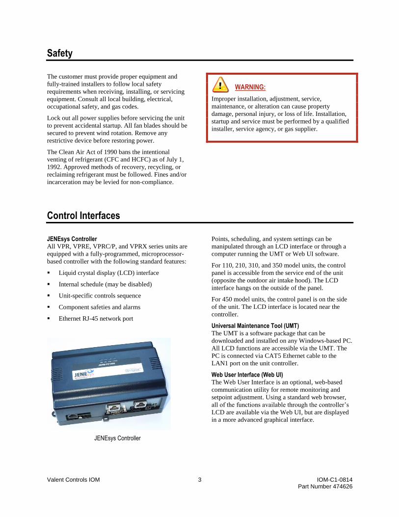
JENEsys Controller All VPR, VPRE, VPRC/P, and VPRX series units are
equipped with a fully-programmed, microprocessor-
based controller with the following standard features:
Liquid crystal display (LCD) interface
Internal schedule (may be disabled)
Unit-specific controls sequence
Component safeties and alarms
Ethernet RJ-45 network port
JENEsys Controller
Points, scheduling, and system settings can be
manipulated through an LCD interface or through a
computer running the UMT or Web UI software.
For 110, 210, 310, and 350 model units, the control
panel is accessible from the service end of the unit
(opposite the outdoor air intake hood). The LCD
interface hangs on the outside of the panel.
For 450 model units, the control panel is on the side
of the unit. The LCD interface is located near the
controller.
Universal Maintenance Tool (UMT) The UMT is a software package that can be
downloaded and installed on any Windows-based PC.
All LCD functions are accessible via the UMT. The
PC is connected via CAT5 Ethernet cable to the
LAN1 port on the unit controller.
Web User Interface (Web UI) The Web User Interface is an optional, web-based
communication utility for remote monitoring and
setpoint adjustment. Using a standard web browser,
all of the functions available through the controller’s
LCD are available via the Web UI, but are displayed
in a more advanced graphical interface.
Valent Controls IOM 4 IOM-C1-0814 Part Number 474626
Using the LCD
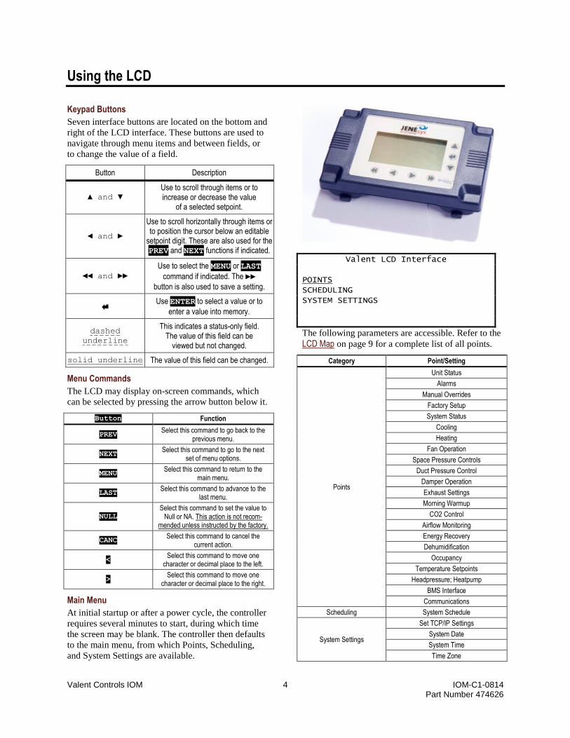
Keypad Buttons
Seven interface buttons are located on the bottom and
right of the LCD interface. These buttons are used to
navigate through menu items and between fields, or
to change the value of a field.
Button Description
▲ and ▼ Use to scroll through items or to increase or decrease the value
of a selected setpoint.
◄ and ►
Use to scroll horizontally through items or to position the cursor below an editable
setpoint digit. These are also used for the PREV and NEXT functions if indicated.
◄◄ and ►► Use to select the MENU or LAST
command if indicated. The ►►
button is also used to save a setting.
Use ENTER to select a value or to
enter a value into memory.
dashed
underline
This indicates a status-only field. The value of this field can be
viewed but not changed.
solid underline The value of this field can be changed.
Menu Commands
The LCD may display on-screen commands, which
can be selected by pressing the arrow button below it.
Button Function
PREV Select this command to go back to the
previous menu.
NEXT Select this command to go to the next
set of menu options.
MENU Select this command to return to the
main menu.
LAST Select this command to advance to the
last menu.
NULL Select this command to set the value to
Null or NA. This action is not recom-mended unless instructed by the factory.
CANC Select this command to cancel the
current action.
< Select this command to move one
character or decimal place to the left.
> Select this command to move one
character or decimal place to the right.
Main Menu
At initial startup or after a power cycle, the controller
requires several minutes to start, during which time
the screen may be blank. The controller then defaults
to the main menu, from which Points, Scheduling,
and System Settings are available.
Valent LCD Interface POINTS SCHEDULING SYSTEM SETTINGS
The following parameters are accessible. Refer to the
LCD Map on page 9 for a complete list of all points.
Category Point/Setting
Points
Unit Status
Alarms
Manual Overrides
Factory Setup
System Status
Cooling
Heating
Fan Operation
Space Pressure Controls
Duct Pressure Control
Damper Operation
Exhaust Settings
Morning Warmup
CO2 Control
Airflow Monitoring
Energy Recovery
Dehumidification
Occupancy
Temperature Setpoints
Headpressure; Heatpump
BMS Interface
Communications
Scheduling System Schedule
System Settings
Set TCP/IP Settings
System Date
System Time
Time Zone

Valent Controls IOM 5 IOM-C1-0814 Part Number 474626
Changing a Setpoint
1. Push any button on the LCD interface to refresh
the display. If the main menu is not shown, press
the MENU button to return to the main menu.
2. Press Enter to select POINTS.
Valent LCD Interface POINTS SCHEDULING SYSTEM SETTINGS
3. Use ▲ and ▼ as well as PREV and NEXT to
navigate to the various setpoints stored in the
controller.
4. When the desired setpoint is underlined, press
Enter to change the value.
5. Modifications are made by changing one
significant digit at a time. Use ◄ and ► to move
left and right between digits. Use ▲ and ▼ to
change the value of the digit.
6. Press Enter to save the change.
Changing the Fan Speed
Each VPR, VPRE, VPRC/P, and VPRX rooftop unit
includes a variable frequency drive (VFD) for the
supply fan. The supply fan speed can be changed
from the LCD.
1. Push any button on the LCD interface to refresh
the display. If the main menu is not shown, press
the MENU button to return to the main menu.
2. Press Enter to select POINTS.
Valent LCD Interface POINTS SCHEDULING SYSTEM SETTINGS
3. Use the NEXT button and ► right arrow button to
navigate to the FAN OPERATION screen.
FAN OPERATION SUPPLY FAN ON SUP FAN STATUS ON SUP FAN SPEED 100 % SUP FAN MIN 50 % SUP FAN MAX 80.0 % EXH FAN ON MENU PREV NEXT LAST
4. Using the ▼button, move the underscore to SUP
FAN MAX and press Enter on the keypad.
5. Use ◄ and ► to move left and right between
digits. Use ▲ and ▼ to change the value of the
digit.
6. Press Enter to save the change.
Verifying Changes
After making changes to any VFD parameters,
confirm the VFD/fan speed by enabling the fan to
operate. The speed, in Hz, is indicated on the front of
the VFD display. If the controller is sending a fan
speed of 100%, fan speed analog output should be 10
VDC and the fan speed should be the design limit.
Manually Overriding a Setpoint
Many setpoints can be manually overridden for
troubleshooting. Refer to the LCD Map on page 9 for a
list of setpoints that can be manually overridden.
Refer to the Manual Override section on page 48 for
definitions of manual override points.
1. Push any button on the LCD interface to refresh
the display. If the main menu is not shown, press
the MENU button to return to the main menu.
2. Press Enter to select POINTS.
Valent LCD Interface POINTS SCHEDULING SYSTEM SETTINGS
3. Press ► to navigate to the MANUAL OVERRIDES
screen.
MANUAL OVERRIDES OVERRIDE MODE DISABLED TIME REMAINING 0 MIN UNIT ENABLE OFF SUPPLY FAN OFF SUPPLY OVERRIDE OFF SUPPLY SPEED 50 % MENU PREV NEXT LAST
4. On the MANUAL OVERRIDES screen, OVERRIDE
MODE is underlined. Press Enter.
5. Press ▲ to change the value to Enabled. Press
Enter to accept the change.
6. Use ▲ and ▼ to navigate to the setpoint to
override. Press Enter.

Valent Controls IOM 6 IOM-C1-0814 Part Number 474626
7. Use ▲ and ▼ to change the value of the
selection or to change the digit. If applicable, use
◄ and ► to move left and right between digits.
8. When the setpoint is modified to the desired
value, push Enter to update the controller.
Wait a few seconds for the value to update. The
controller does not need to be restarted for the
override to take effect.
Manual Override mode is in effect for 4 hours, after
which setpoints return to the previous state or Auto.
To cancel the manual override mode before it
expires, change OVERRIDE MODE to False. The TIME
REMAINING point displays how much time remains
before the override mode expires automatically.
Changing a Schedule
The default schedule of the controller is 24-hour
Occupied.
1. Push any button on the LCD interface to refresh
the display. If the main menu is not shown, press
the MENU button to return to the main menu.
2. Press ▼ to move the underline cursor to
SCHEDULING and press Enter.
Valent LCD Interface POINTS SCHEDULING SYSTEM SETTINGS
3. When the SCHEDULE menu is shown, press
Enter again. The SCHEDULE DETAILS screen is
then displayed with a seven-day, 24-hour grid.
SCHEDULE DETAILS
TIMES S M T W T F S
8:00 AM ___
9:00 AM
10:00 AM
11:00 AM
SETTING:
MENU CANC
4. Using the left and right arrows, move the visible
curser to the day a schedule change is desired.
Press Enter to edit an existing event (if cursor
is located on an existing event) or create a new
one (if cursor is located on an open time slot).
5. If an existing event is selected, the SELECT
EVENT menu appears. Press Enter to edit the
event or ▼ to underline the DELETE EVENT
menu option. Press Enter to delete the event
from the current schedule.
SELECT EVENT EDIT EVENT 1 - 8:00 AM DELETE EVENT 1
BACK
6. The event menu is identical whether editing an
existing event or creating a new event. Use ▲
and ▼ to select the desired field and press
Enter to change its value. Press Enter to
complete the change.
MONDAY EVENT START TIME: 8:00 AM END TIME: 10:00 AM VALUE: OCCUPIED MENU SAVE CANC
7. To temporarily disable an event, change the
Value field from OCCUPIED to UNOCCUPIED.
MONDAY EVENT START TIME: 8:00 AM END TIME: 10:00 AM VALUE: UNOCCUPIED MENU SAVE CANC
8. Press SAVE to save the settings in the controller.
Any request for occupancy from the push button on a
space temperature sensor will be effective for two
hours.

Valent Controls IOM 7 IOM-C1-0814 Part Number 474626
Changing the IP Address
The local display may be used to change the default
network settings of the controller.
WARNING: Setting the IP address to an incorrect value may cause
the controller to lock up and may require replacing
the controller. Make sure the IP address, gateway,
and subnet mask are set correctly before saving the
new settings.
The controller ships with the following default
settings:
Default Gateway: 192.168.1.1
IP Address: 192.168.1.101
Subnet Mask: 255.255.255.0
1. Push any button on the LCD interface to refresh
the display. If the main menu is not shown, press
the MENU button to return to the main menu.
2. Press ▼ to move the underline cursor to SYSTEM
SETTINGS and press Enter.
Valent LCD Interface POINTS SCHEDULING SYSTEM SETTINGS
3. Press Enter to select SET TCP/IP
SETTINGS.
JENESYS SYSTEM SETTINGS SET TCP/IP SETTINGS SYS DATE: AUG 17, 2012 SYS TIME: 15:02 TIMEZONE: AMERICA/CHICA (-5/-6) MENU CANC
4. Press Enter to select IP ADDRESS.
JENESYS TCP/IP SETTINGS IP ADDRESS: 192.168. 1.200 SUBNETMASK: 255.255.255. 0 GATEWAY: 192.168. 1. 1 MENU SAVE
5. Use ◄ and ► to move left and right between
digits. Use ▲ and ▼ to change the value of the
digit.
The subnet mask and gateway can be changed
using a similar method. A corresponding
gateway must be entered for the IP address.
6. When all changes are complete, select SAVE. The
display will indicate that a reboot is required.
Move the cursor under the desired response
(YES/NO) and press Enter. Allow several
minutes for the controller to reboot and return to
normal operation.
-REBOOT- CONTROLLER MUST REBOOT TO SAVE THESE SETTINGS
CONTINUE?
YES NO
Reviewing BACnet IP or MSTP Settings
The JENEsys controller’s BACnet IP and MSTP
settings are available in the POINTS menu of the
LCD. To access them:
1. Push any button on the LCD interface to refresh
the display. If the main menu is not shown, press
the MENU button to return to the main menu.
2. Press Enter to select POINTS. The Unit Status
menu is the first menu displayed.
3. Press the right double arrows below LAST to
jump to the last tab of the points menu, which is
for COMMUNICATIONS.
BACnet is an optional feature which must be
licensed. Although data will appear for viewing on
the communication menu, settings cannot be changed
if the unit has not been licensed.
COMMUNICATIONS COMM LICENSE ENABLED ****BACNET ***** OBJECT ID 11 NETNUMBER IP 1 NETNUMBER MSTP 2 MSTP ADDRESS 1 MENU PREV NEXT LAST
4. Make sure that COMM LICENSE is set to Enabled
and all other settings are set as desired. Verify
that your device can be discovered at your head-
end system.
Refer to Using BACnet Communications on page 23 for
further information about BACnet communications.

Valent Controls IOM 8 IOM-C1-0814 Part Number 474626
Reviewing LonWorks Settings
The LonWorks settings for the JENEsys controller
are available in the POINTS menu of the LCD
display. To access them:
1. Push any button on the LCD interface to refresh
the display. If the main menu is not shown, press
the MENU button to return to the main menu.
2. Press Enter to select POINTS. The UNIT
STATUS menu is the first menu displayed.
3. Press the right arrows below LAST to jump to the
last tab of the points menu, which is for
COMMUNICATIONS.
4. Use ▼ to scroll down to reach the LonTalk
points.
LonTalk is an optional feature which must be
licensed. Although data will appear for viewing on
the communications menu, settings cannot be
changed if the unit has not been licensed.
COMMUNICATIONS BAUDRATE 9600 MAX MASTERS 127 MAX INFO FRAMES 20 ****LONTALK ***** NID 04 1E 0F E8 03 00 SERVICE PIN FALSE MENU PREV NEXT LAST
Service Pin
The SERVICE PIN is available to help discover the
Valent unit on the building’s LON network.
1. On the LonWorks menu, navigate to SERVICE
PIN.
2. Press Enter to make the point editable. Toggle
▲ or ▼ to make the value TRUE, then press
Enter. This sends a service pin signal over the
LON network. This can be repeated as many
times as necessary.
Refer to Using LonTalk Communications on page 23 for
further information about LonTalk communications.

Valent Controls IOM 9 IOM-C1-0814 Part Number 474626
LCD Map
This list contains all points accessible on the LCD, in the menu order and list order in which they appear on the
screen. Setpoints in this list with a solid underline can be edited. All others are view-only. On the LCD screen, a
solid cursor underline indicates an editable setpoint; a dashed cursor underline indicates a view-only point. These
points are also accessible from the UMT or Web UI. Refer to the following sections for more information: Setpoint List on page 27 and Setpoint Descriptions on page 37.
UNIT STATUS ALARMS
MANUAL OVERRIDES
FACTORY SETUP SYSTEM STATUS COOLING HEATING FAN OPERATION SUPPLY TEMP
DX COIL TEMP
SPACE TEMP
SPACE RH
SPACE ENTH
OA TEMP
OUTDOOR RH
OUTDOOR ENTH
EXHAUST TEMP
MIXED AIR TEMP
RESET
ALARM STATUS
SHUTDOWN INPUT
SUPPLY FAN
DAMPER SWITCH
SUPPLY TEMP SEN
HIGH SUP TEMP
LOW SUP TEMP
SPACE STATIC
DUCT STATIC
HPC_LPC_A
HPC_LPC_B
REF PRESSURE A
REF PRESSURE B
SPACE TEMP
OA TEMP
OA HUMIDITY SEN
EXHAUST TEMP
MIXED TEMP SEN
EXHAUST FAN
SPACE HUMIDITY
CO2 SENSOR
HW ROTATION
FILTERS
WSHP REF LOW PSI
FREEZESTAT
OVERRIDE MODE
TIME REMAINING
UNIT ENABLE
SUPPLY FAN
SUPPLY OVERRIDE
SUPPLY SPEED
EXHAUST FAN
EXHAUST OVERRIDE
EXHAUST SPEED
HEAT WHEEL
WHEEL OVERRIDE
WHEEL SPEED
OA DAMPER CTRL
OA DMP OVERRIDE
HEAT COOL
COMPRESSOR1
COMPRESSOR2
COMPRESSOR3
COMPRESSOR4
DIGITAL SCROLL
MOD HEAT
ELEC HEAT
HEAT 1
HEAT 2
HEAT 3
SPACE SETPT
SUPPLY SETPT
HOT GAS REHEAT
REHEAT OVERRIDE
FLAT PLATE
F PLATE OVERRIDE
PRE-HEATER
COIL SAFETY
HEAD PRESSURE
FAN VFD/VALVE A
FAN VFD/VALVE B
REVERSING VALVE
REVERSING VALVE
COMM VAL
DAMPER CONFIG
FAN CONFI
CO2 CTRL VAL
EX FAN CTRL
REM DAMPER
PRE-HEATER
AIR MEAS VAL
HEAT VAL
COOL VAL
ENERGY RECOV
UNIT TYPE
ECONO
AMD TYPE
WEB UI
RE MON
OPTIMAL SS
HEAT PUMP
MWU
NIGHT PURGE
REHEATDEHUM
HW ROTATION
SPACE SETPOINT
FUTURE
FUTURE
I/O MAP
VERSION
SO#
TAG
SYSTEM ENABLE
SYSTEM STATUS
SYSTEM START
END SWITCH
STATUS
OCC BY
OP MODE
COOLING PID
HEATING PID
ECON PID
ECON STATUS
REHEAT OUTPUT
REVERSING VLV
HP HEAT PID
CHW/DIGITAL OUT
COMP 1
COMP 2
COMP 3
COMP 4
AMB LOCKOUT
DEHUM STATUS
ELECTRIC
MODULATING
STAGE 1
STAGE 2
STAGE 3
AMB LOCKOUT HW CASE HEAT ENABLE
HW CASE HEAT SPT
SUPPLY FAN
SUP FAN STATUS
SUP FAN SPEED
SUP FAN MIN
SUP FAN MAX
EXH FAN
EXH FAN STATUS
EXH FAN SPEED
SPACE PRESSURE CONTROL
DUCT PRESSURE CONTROL
DAMPER OPERATION
EXHAUST SETTINGS MORNING WARMUP
CO2 CONTROL AIR FLOW
MONITORING ENERGY RECOVERY
PRESSURE
SETPOINT
HIGH LIMIT
SUPPLY REACTION EXHAUST REACTION
PRESSURE
SETPOINT
HIGH LIMIT
SUPPLY REACTION
OA DAMPER
DAMPER CONFIG
OAD MIN POS
OAD MAX POS
ENTHALPY SETPT
DRY BULB SPT
EX FAN DAMP POS
EX FAN MAX SPEED
EX FAN MIN SPEED
EX SPEED OFFSET
ENABLE
WARM UP STATUS
CO2 LEVEL
INSTALLED
SETPOINT
SUPPLY
EXHAUST
AMD
SETPOINT
WHEEL STATUS
WHEEL OUTPUT
ENERGY RECOV
PREHEAT
DEFROST MODE
DEHUMIDIFICATION OCCUPANCY TEMPERATURE
SETPOINTS HEADPRESSURE;
HEATPUMP BMS INTERFACE COMMUNICATIONS
DX COIL SETPT
SPACE RH SPT
OA DEWPOINT SPT
OCC STATUS
OCC BY
SCHEDULE
SPACE SETPT
SPACE OFFSET
SUPPLY CALC
SUPPLY SETPT
SUPPLY MIN COOL
SUPPLY MIN HEAT
SUPPLY MAX COOL
SUPPLY MAX HEAT
UNOCC HEAT
UNOCC COOL
SUPPLY CONTROL
HEAD PRESSURE
HEAD PRESSURE
COMP OFFVLVPOS
WSHP SUC LOWLIM
VALVE A OUTPUT
VALVE B OUTPUT
PRESSURE CIRC A
PRESSURE CIRC B
ASHP
OAT
OA RH%
SPACE TEMP
SPACE RH
CO2
SPACE STATIC
DUCT STATIC
SF OVERRIDE
SF SPEED
EF OVERRIDE
EF SPEED
OAD OVERRIDE
OAD POS
OCC ENABLE
BAS OCC CMD
HEAT DISABLE
COOL DISABLE
SHUTDOWN
SPACE SETPOINT
RH SETPOINT
S STATIC SETPOINT
SUPPLY SETPOINT
D STATIC SETPOINT
CO2 SETPOINT
UNOCC COOL SPT
UNOCC HEAT SPT
UNOCC HUMID SPT
COMM LICENSE
****BACNET
OBJECT ID
NETNUMBER IP
NETNUMBER MSTP
MSTP ADDRESS
BAUDRATE
MAX MASTER
MAX INFO FRAMES
****LONTALK
NID
SERVICE PIN

Valent Controls IOM 10 IOM-C1-0814 Part Number 474626
Using the Universal Maintenance Tool (UMT)
Installing the Software
The UMT software is currently provided on a CD
included in the control panel of the unit. It is also
currently available for download at:
http://www.valentair.com/Portals/4/Software/UMT.zip
The software must be installed on a Windows-based
PC, and runs the best using a Windows XP-based
operating system.
Compatibility with Windows Vista or Windows 7
The software will also run using Windows Vista or
Windows 7, but it must be configured for this.
1. Right click on the UMT installer icon.
2. Click on Properties.
3. Select the Compatibility tab.
4. Check the box for Run this program in
compatibility mode.
5. Select Windows 2000.
6. Select Run this program as an administrator.
7. Click on OK.
Connecting to the Controller
1. Connect the computer to the JENEsys controller
using a CAT5 Ethernet cable. The computer
should be connected through its LAN connection
(Ethernet port). The controller should be
connected using the LAN1 port as shown in the
following figure.
UMT connection on the bottom of the JENEsys controller.
Configuring the IP Address for the PC
To successfully connect with the Valent unit
controller, the IP address of the PC must be in the
same range as the controller, but not identical. Every
Valent unit is shipped from the factory with the same
default IP address:
192.168.1.101 [Valent unit]
A suggested IP address for the computer
communicating with the Valent unit is:
192.168.1.200 [PC]
Configuring the IP Address Using Windows XP
To change the static IP address of the PC that is
running Windows XP, follow these steps.
1. Click START or the Windows icon in the lower
left corner of the screen.
2. Select Control Panel.
3. Select Network Connections.
4. Identify the target LAN connection with the
status of Network cable unplugged.

Valent Controls IOM 11 IOM-C1-0814 Part Number 474626
5. Right-click on the identified Local Area
Connection. Select Properties.
6. Use the slider bar to scroll down until the
selection Internet Protocol (TCP/IP) is visible.
7. Highlight Internet Protocol (TCP/IP) and press
the Properties button.
8. To assign a new IP address manually, click on
Use the following IP address.
9. Type in the following information and press OK
when completed.
IP address: 192.168.1.200
Subnet mask: 255.255.255.0
If the controller does not connect, return to this
screen and, in addition to the previous fields,
enter the following:
Default gateway: 192.168.1.1
10. The system returns to the Local Area Connection
Properties screen. Click on Close to exit this
screen.
The IP address of the Valent unit controller can be
changed to be in the same range as the connected PC
as well, especially for instances when the PC and
Valent unit are connected to the building’s
network/LAN. In those cases, request a static IP
address from the network administrator and use the
LCD or UMT to edit the address of the Valent unit.

Valent Controls IOM 12 IOM-C1-0814 Part Number 474626
Configuring the IP Address Using Windows 7
To change the static IP address of the PC that is
running Windows 7, follow these steps.
1. Click on the Windows orb icon in the lower left
corner of the screen:
2. Select Control Panel.
3. Select Network and Sharing Center.
If the Control Panel is displayed by category, select
View Network Status and Tasks in the Network and
Internet category.
4. On the network screen, choose Change adapter
settings.
5. Find your Local Area Connection. If you need to
determine which connection to select, simply
unplug the network cable from the PC. The
adapter status should change to Not Connected.
Reconnect the cable.
6. Right click on the Local Area Connection, then
select Properties.
7. Select TCP/IPv4, then click on Properties.

Valent Controls IOM 13 IOM-C1-0814 Part Number 474626
8. On the TCP/IPv4 screen, click on Use the
following IP address.
Enter the following in the text boxes:
IP address: 192.168.1.200
Subnet mask: 255.255.255.0
If the controller does not connect, return to this
screen and, in addition to the previous fields,
enter the following:
Default gateway: 192.168.1.1
9. Press OK to save the settings.
Logging on to the Controller
1. Start the UMT software program by double
clicking on the icon on the Windows desktop.
2. During startup, the UMT checks for JENEsys-
based controllers on the current network.
3. When the controller is identified, double-click on
the controller name to continue. Or click on the
controller name, then click OK at the bottom of
the window.
If a controller is not found on the network, verify
the IP settings for both the laptop and the
controller. They should be in the same range, but
not the same.
NOTE: On occasion the JENEsys controller will
not announce itself. If this happens, press Cancel
on the Search window. On the Connect screen,
manually type in the IP address of the JENEsys
controller with all of the settings shown in the
table below, then press Connect.
Occasionally, if the controller has been running
for a long period, the Ethernet port goes to sleep
and loses connection. Reboot the controller to
reconnect.
4. The Connect screen is displayed. Select Platform
& Service from the task list.
5. Enter the following items. Usernames and
passwords are case sensitive.
IP Address 192.168.1.101
Platform Port 3011
Platform Username tridium
Platform Password niagara
Fox Port 1911
Fox Username admin
Fox Password [blank]
6. Click on the Connect button to establish the
connection between the computer (via UMT) and
the controller.
The UMT software package will connect to the
selected unit and download data from the individual
station. Monitor the progress bar on the screen for the
status of this operation. The download process should
take several minutes.
The Station Director tab is the first screen displayed.

Valent Controls IOM 14 IOM-C1-0814 Part Number 474626
Refer to the UMT Map on page 18 for a complete list
of all points accessible on the UMT.
Changing System Time and Date
1. Select the Platform tab.
2. Click on the double arrows next to System Time
and Date.
3. A small editing window appears. Change the
time and date as required, then select Save.
Instead of directly entering the time and date,
information can be automatically updated from
the local PC. To do this, select Use Local from
the Time Zone drop down menu, then select
Save.
Changing the IP Address
Use the TCP/IP Configuration utility to edit the
network address and related parameters for the
controller.
WARNING: Setting the IP Address to an incorrect value may
cause the controller to lock up and will require
replacing the controller. Make sure the IP address,
gateway, and subnet mask are set correctly before
saving the new settings.
The controller ships with the following default
settings:
Default Gateway: 192.168.1.1
IP Address: 192.168.1.101
Subnet Mask: 255.255.255.0
1. Select the Platform tab.
2. Click on the double arrows to the right of
TCP/IP Configuration.
3. Expand Interface 1 by clicking on the double
arrows to the right of the title.
IMPORTANT:
Do not change the parameters for Interface 2.
4. Edit the Gateway, IP Address, and Subnet Mask
as required, then click on Save TCPIP.
IMPORTANT:
Do not select Enabled for DHCP; this can make
the controller difficult to access.
Valent Controls IOM 15 IOM-C1-0814 Part Number 474626
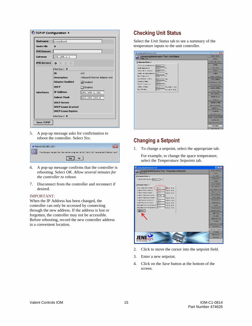
5. A pop-up message asks for confirmation to
reboot the controller. Select Yes.
6. A pop-up message confirms that the controller is
rebooting. Select OK. Allow several minutes for
the controller to reboot.
7. Disconnect from the controller and reconnect if
desired.
IMPORTANT:
When the IP Address has been changed, the
controller can only be accessed by connecting
through the new address. If the address is lost or
forgotten, the controller may not be accessible.
Before rebooting, record the new controller address
in a convenient location.
Checking Unit Status
Select the Unit Status tab to see a summary of the
temperature inputs to the unit controller.
Changing a Setpoint
1. To change a setpoint, select the appropriate tab.
For example, to change the space temperature,
select the Temperature Setpoints tab.
2. Click to move the cursor into the setpoint field.
3. Enter a new setpoint.
4. Click on the Save button at the bottom of the
screen.

Valent Controls IOM 16 IOM-C1-0814 Part Number 474626
Changing the Fan Speed
Each VPR, VPRE, VPRC/P, and VPRX rooftop unit
includes a variable frequency drive (VFD) for the
supply section. The supply fan speed can be changed
from the UMT.
1. Select the Fan Operation tab.
2. If the Writable Points are not visible, click on the
double arrows by the heading.
3. Locate the Supply Fan Max Speed Setpoint.
Click to move the cursor into the setpoint field.
4. Enter a new maximum fan speed.
5. Click on the Save button at the bottom of the list.
Manually Overriding a Setpoint
Many setpoints can be manually overridden during
troubleshooting. Refer to the Manual Override section
on page 48 for definitions of override points.
1. To override a setpoint, select the Manual
Overrides tab.
2. Set Enable Override to Enabled.
3. Click to move the cursor into the desired setpoint
field. Enter a new value or change the state.
4. Click on the Save button at the bottom of the
setpoint list.
A Manual Override is in effect for 4 hours, after
which setpoints return to the previous state or Auto.
To stop an override, set the point to Auto. To cancel
the manual override mode before it expires, set
Enable Override to Disabled.

Valent Controls IOM 17 IOM-C1-0814 Part Number 474626
Changing a Schedule
1. To edit a schedule, select the Occupancy tab.
2. Locate the Schedules heading and click on the
double arrows to reveal the schedules for the unit
controller.
The occupied hours of operation are displayed
for each day of the week. The default schedule in
the controller is 24-hour Occupied.
3. To edit the schedule, use the mouse to drag the
start/stop times for each day. Simply click on the
dividing line in the column and push it up or
down to a new time. Event Start and Event
Finish times can also be edited directly using the
fields near the bottom of the screen.
4. When the changes are complete, press Save at
the bottom of the screen.
Scheduling a Special Event
A one-time exception to the regular weekly schedule
can be configured as a special event.
1. Click on the Special Events tab at the bottom of
the Schedule screen.
2. On the calendar at the top of the screen, click on
the day to schedule a special event.
3. Enter the occupied and unoccupied times on the
right side of the display in the same manner a
regular schedule would be configured.
4. Click Save at the bottom of the screen.
The new settings will be valid only on the day
specified.
Viewing Schedule Properties
From the Schedule screen, click on the Properties tab
at the bottom of the screen. Information on the
Properties tab should be changed only under direction
of the factory.
Viewing the Schedule Summary
From the Schedule screen, click on the Summary tab.
Click on a date to see a summary of all schedule
settings for that day, including the weekly settings
and any special events.

Valent Controls IOM 18 IOM-C1-0814 Part Number 474626
UMT Map
This list contains all points accessible on the UMT. Setpoints in this list with a solid underline can be edited. All
others are view-only.
AIR FLOW MONITORING
AMD Airflow
AMD Damper Area
AMD K Factor
AMD M Factor
AMD Thermal Dispersion Max Velocity
AMD Transducer Range
Damper Setpoint
Exhaust Airflow
Exhaust Inlet Cone K Factor
Supply Airflow
Supply Inlet Cone K Factor
Type
ALARMS
Alarm Reset
Alarm Status
Clogged Air Filter
CO2 Sensor
Duct Static Pressure
Exhaust Fan
Exhaust Temperature Sensor
Freezestat
Heat Wheel Rotation
High Pressure/Low Pressure Cutout Circuit A
High Pressure/Low Pressure Cutout Circuit B
Mixed Air Temperature Sensor
Outdoor Air Damper End Switch
Outdoor Air Temperature Sensor
Outdoor Relative Humidity Sensor
Refrigerant Pressure Transducer A
Refrigerant Pressure Transducer B
Shutdown Input
Space Humidity Sensor
Space Static Pressure
Space Temperature Sensor
Supply Fan
Supply High Temp Alarm Delay
Supply Temp High
Supply Temp Low
Supply Temperature Sensor
WSHP Low Refrigerant Pressure
BACNET NETWORK ADVANCED
Time Synch
UDP Port Number
CO2 CONTROL
CO2 Control
CO2 Deadband
CO2 Level
CO2 Setpoint
Control Enabled
Maximum Damper Control Position
COOLING
10 Volts Opens Chilled Water Valve
AMB Lockout
Chilled Water Valve Off Position
Compressor 1 Ambient Lockout Setpoint
Compressor 1 Output
Compressor 2 Ambient Lockout Setpoint
Compressor 2 Output
Compressor 3 Ambient Lockout Setpoint
Compressor 3 Output
Compressor 4 Ambient Lockout Setpoint
Compressor 4 Output
Cooling Execution Time
Cooling Integral Constant
Cooling Proportional Constant
Digital/Chilled Water Output
Enable Compressor 1 Ambient Lockout
Enable Compressor 2 Ambient Lockout
Enable Compressor 3 Ambient Lockout
Enable Compressor 4 Ambient Lockout
High/Low Pressure Trip Shutdown Circuit
Shutdown Unit During High/Low Pressure Trip
DAMPER OPERATION
Damper Configuration
Damper Output
Damper Remote Control
Economizer Configuration
Economizer Enable Setpoint Enthalpy
Economizer Enable Setpoint Temperature
Outdoor Air Damper Maximum
Outdoor Air Damper Minimum
Unoccupied Outdoor Air Damper Minimum
DEHUMIDIFICATION
Dehumidification Has Priority
DX Coil Setpoint
Occupied Space Humidity Low Deadband
Outdoor Dewpoint Setpoint
Overcool Offset
Space Dewpoint Dehumidification Cutout
Space Relative Humidity Setpoint
Unoccupied Space Humidity Low Deadband
Unoccupied Space Humidity Setpoint
DUCT PRESSURE CONTROL
Duct Pressure
Duct Pressure High Limit Setpoint
Duct Pressure Setpoint
Supply Fan Reaction Speed
ENERGY RECOVERY
Defrost Mode
Flat Plate Exhaust Defrost
Heat Wheel Exhaust Defrost
Heat Wheel Output
Heat Wheel Speed/Damper Position
Heat Wheel Status
Preheat Ambient Setpoint
Preheat Output
EXHAUST SETTINGS
Configuration
Exhaust Fan Enable Damper Position
Exhaust Fan Max Speed
Exhaust Fan Min Speed
Exhaust Fan Offset
FACTORY SETUP
Airflow Monitoring Type
AMD Type
CO2 Control
Communications Type
Cooling Package
Damper Configuration
Economizer
Energy Recovery Configuration
Exhaust Fan Control Type
Future
Future
Heat Pump
Heat Wheel Rotation Sensor
Heating Package
I/O Map
Morning Warm Up
Night Purge
Optimal SS
Pre-Heater
Refrigerant Monitoring
Reheat Dehumidification
Remote Damper Control
Saved Controls Number
Space Setpoint
Supply Fan Configuration
Unit Type
Web UI
FAN OPERATION
Exhaust Fan Output
Exhaust Fan Speed
Exhaust Fan Status
Supply Fan Max Speed Setpoint
Supply Fan Min Speed
Supply Fan Output
Supply Fan Speed
Supply Fan Status
Unoccupied Supply Fan Speed Offset
HEAD PRESSURE;HEAT PUMP
1.0 Air Cooled Head Pressure Setpoint
2.0 Air Cooled Head Pressure Dehumidification Setpoint
2.0 Air Cooled Head Pressure Setpoint
ASHP Defrost Cancel Condensing Setpoint
ASHP Defrost Status
ASHP Electric Heat Defrost
ASHP Electric Heat Defrost Enable. Call Valent for Password.
ASHP Low Ambient Compressor Lockout Setpoint
Head PR Output 1
Head PR Output 2
Refrigerant Pressure Circuit A
Refrigerant Pressure Circuit B
Valve A Output
Valve B Output
WSHP Cold Start Duration
WSHP Cold Start Enable Temp
WSHP Compressor Off Water Valve Position
WSHP Condenser Temperature Setpoint
WSHP Suction Temp Low Limit Safety
WSHP Valve Max Closed Position

Valent Controls IOM 19 IOM-C1-0814 Part Number 474626
HEATING
10 Volts Opens Hot Water Valve
AMB Lockout
Electric Heat Output
Heating Execution Time
Heating Integral Constant
Heating Proportional Constant
Hot Water Case Heat Outside Temp Enable
Hot Water Case Heat Setpoint
Hot Water Valve Off Position
Modulating Heat Output
Stage 1
Stage 2
Stage 3
MANUAL OVERRIDES
Coil Low Limit Safety
Cooling Relay 1 Override
Cooling Relay 2 Override
Cooling Relay 3 Override
Cooling Relay 4 Override
Cooling/Heating Loop Override
Cooling/Heating Loop Override Auto/Manual
Cooling/Heating Override Auto/Manual
Digital Compressor Signal Override
Electric Heat Signal Override
Electric Pre-Heat Override
Enable Override
Exhaust Fan Control Auto/Manual
Exhaust Fan Override
Exhaust Fan Speed
Fan VFD/Valve A
Fan VFD/Valve B
Flat Plat Control Auto/Manual
Flat Plate Override
Gas Burner/Hot Water Valve Signal Override
Head Pressure Auto/Manual
Heat Wheel Control Auto/Manual
Heat Wheel Override
Heat Wheel Speed
Heating Relay 1 Override
Heating Relay 2 Override
Heating Relay 3 Override
Hot Gas Reheat Control Auto/Manual
Hot Gas Reheat Override
Outside Air Damper Auto/Manual
Outside Air Damper Override
Override Mode Status
Override Mode Status
Reversing Valve Auto/Manual
Reversing Valve Position
Space Temperature Override
Supply Fan Control Auto/Manual
Supply Fan Override
Supply Fan Speed
Supply Temperature Override
System Enable
Time Remaining
MORNING WARM UP
Enable
Morning Warm Up
Morning Warmup Status
NIGHT PURGE
Night Purge
Night Purge Enable
OCCUPANCY
Enable Occupancy Auto Mode
Occupancy Status
Occupied By
System Schedule
Timed Override Duration
OPTIMAL START STOP
Earliest Start Time
Earliest Stop Time
Enable Optimal Start
Enable Optimal Stop
SCHEDULE
Properties
Special Events
Summary
Weekly Schedule
SPACE PRESSURE CONTROL
Exhaust Fan Reaction Speed
Setpoint
Space Pressure
Space Pressure High Limit Setpoint
Supply Fan Reaction Speed
SYSTEM STATUS
Cooling PID Output
Economizer PID Output
Economizer Status
End Switch Contact
Heat Pump Heat PID Output
Heating PID Output
Occupancy Controlled By
Occupancy Status
Operating Mode
Reheat Output
Reversing Valve Output
System Enable
System Shutdown Status
System Start Command
TEMPERATURE SETPOINT
DX Coil Low Limit Safety
DX Coil Low Limit Setpoint
Space Temperature Setpoint
Space Temperature Setpoint Offset
Supply Air Cooling High Deadband
Supply Air Cooling Low Deadband
Supply Air Heating High Deadband
Supply Air Heating Low Deadband
Supply Air Maximum Cooling Setpoint
Supply Air Maximum Heating Setpoint
Supply Air Minimum Cooling Setpoint
Supply Air Minimum Heating Setpoint
Supply Air Temperature Control
Supply Air Temperature Setpoint
Supply Setpoint Calculated
Supply Temperature High Limit
Supply Temperature Low Limit
Temperature Control PID Deadband Enable
Unoccupied Space Cooling Setpoint
Unoccupied Space Heating Setpoint
UNIT STATUS
DX Coil Leaving Temperature
Exhaust Temp
Mixed Air Temperature
Outdoor Air Relative Humidity
Outdoor Air Temperature
Outdoor Dewpoint
Outdoor Enthalpy
Space Dewpoint
Space Enthalpy
Space Relative Humidity
Space Temperature
Supply Temperature
WINTER RAMP
Enable Winter Ramp
Winter Ramp Control Type
Winter Ramp Type In Control
NDIO NETWORK
DDC1 34pt Standard Points Table
DDC2 16pt Options Points Table
DDC3 16pt SDR Points Table
LON NETWORK
LonWorks Settings
Points Table
SNVT Table
BACNET NETWORK
Bacnet MSTP Settings
Bacnet Table

Valent Controls IOM 20 IOM-C1-0814 Part Number 474626
Using the Web User Interface (Web UI)
Connecting to the Network
To use the Web UI, the controller must be connected
to the local area network. Using a standard CAT5
Ethernet cable, connect the PC to the JENEsys
controller as shown in the following figure.
Web UI connection on the bottom of the JENEsys controller.
Configuring the IP Address for the PC
To successfully connect with the Valent unit
controller, the IP address of the PC must be in the
same range as the controller, but not identical.
Follow the process in Configuring the IP Address for the PC on page 10.
Logging On to the Web Interface
1. To access the JENEsys program, type the IP
address of the controller into the web browser.
2. The login screen then appears.
Enter the following login information:
Username: admin
Password: [blank]
The username and password are case sensitive.
Click the Login button
3. The Status screen appears.
4. Select the desired tab from the top of the screen.
The data displayed on each tab is a combination
of view-only and editable information. All data
that is accessible from the LCD is available via
the Web UI.
Changing a Setpoint
1. Click on the Setpoints and Setup tab.
2. Click on the button to the right of the setpoint.
For example, to change the space temperature,
click on the Temp button to the right of Space
Temp Setpoint.

Valent Controls IOM 21 IOM-C1-0814 Part Number 474626
3. A small Set window appears. Enter a new value,
then click OK.
4. The change will take effect in the setpoint list.
Changing the Fan Speed
To change the fan speed, adjust the Supply Fan Max
Speed setpoint.
1. Click on the Setpoints and Setup tab.
2. Locate the Supply Air Setpoints group on the
screen.
3. Locate the Supply Fan Max Speed setpoint, and
click on the Max Speed button to the right.
4. A small Set window appears. Enter the new fan
speed, then click OK.
The change is then reflected on the Setpoints and
Setup screen.
Manually Overriding a Setpoint
Many setpoints can be manually overridden during
troubleshooting. Refer to the Manual Override section
on page 48 for definitions of override points.
1. Click on the Manual Override tab.
2. Set Enable Manual Override to On.
3. Locate the setpoint to override.
4. Depending on the setpoint, to override the point:
Click on the Override button.
Click on the On or Off button.
Click and move the slider button to increase
or decrease the value.
Click on the 0-100% button, then use the
pop-up Set screen to enter a new value.
The change is reflected for the setpoint on the
Manual Override screen.
The manual override mode is in effect for four hours,
after which setpoints return to the previous state or
Auto.
To stop an override, click on the Auto button. To
cancel the override mode before it expires, set Enable
Manual Override to Off.

Valent Controls IOM 22 IOM-C1-0814 Part Number 474626
Changing a Schedule
1. To access the schedules, click on the Setpoints
and Setup tab.
2. Locate the Occ Schedule setpoint midway down
the screen.
3. Click on the Schedule button.
4. The Weekly Schedule is displayed. This screen
can be used to control the unit with a set
schedule for each day of the week. The default
schedule of the controller is 24-hour Occupied.
5. To edit the schedule, use the mouse to drag the
start/stop times for each day. Click on the
dividing line in the column and push it up or
down to a new time. Event Start and Event
Finish times can also be edited directly using the
fields near the bottom of the screen.
6. When the changes are complete, click on Save.
Refer to the UMT scheduling section on page 17 for
information on using the other schedule features:
Scheduling a Special Event Viewing Schedule Properties Viewing the Schedule Summary

Valent Controls IOM 23 IOM-C1-0814 Part Number 474626
Using BACnet Communications
Wiring
The connection for BACnet IP is a standard CAT5
Ethernet port which is located on the bottom of the
controller.
The connection for BACnet MSTP should be made
with shielded 18-22 AWG, twisted pair, stranded
wire (Belden 3106A or Belden 3107A) connected to
the three-position RS-485 connector on the bottom of
the controller.
BACnet IP connection
BACnet MSTP connection
BACnet connections on the bottom of the JENEsys controller.
Changing the BACnet IP Settings
The BACnet IP settings for the JENEsys controller
are available in the POINTS menu of the LCD
display. For information on how to access the IP
settings, refer to Reviewing BACnet IP or MSTP Settings
on page 7.
BACnet is an optional feature which must be
licensed. Although data will appear for viewing on
the communication menu, settings cannot be changed
if the unit has not been licensed.
Changing the BACnet MSTP Settings
The BACnet MSTP setting for the JENEsys
controller are available in the POINTS menu of the
LCD display. For information on how to access the
MSTP settings, refer to Reviewing BACnet IP or MSTP Settings on page 7.
BACnet is an optional feature which must be
licensed. Although data will appear for viewing on
the communication menu, settings cannot be changed
if the unit has not been licensed.
Using LonTalk Communications
Wiring
The wiring for LonTalk communications should be
made with shielded 18-22 AWG, twisted pair,
stranded wire connected to the two-port LonTalk
connector on the TOP of the controller.
LonTalk adapter on the top side of the controller (orange plug)
Checking the LonWorks Settings
The JENEsys controller’s LonWorks settings are
available in the POINTS menu on the LCD. For more
information, refer to Reviewing LonWorks Settings on
page 8.
LonTalk is an optional feature which must be
licensed. Although data will appear for viewing on
the communications menu, settings cannot be
changed if the unit has not been licensed.

Valent Controls IOM 24 IOM-C1-0814 Part Number 474626
Input/Output Points
34-Point Module
Universal Input Terminals Type Notes
1 Supply Air Temperature U1 0V
10K Thermistor, Type III
2 Cooling Coil Leaving Air Temperature 0V U2
10K Thermistor, Type III
3 Outdoor Air Temperature U3 0V
10K Thermistor, Type III
4 Space Temperature 0V U4
10K Thermistor, Type III
5 Outdoor Air Relative Humidity U5 0V
0-10 VDC (0-100%)
6 Space Relative Humidity 0V U6
0-10 VDC (0-100%)
7 Damper End Switch Contact U7 0V
Contact Closed = End Switch(es) Made, Damper(s) OPEN
8 Supply Fan Status 0V U8
Contact Closed = Fan ON
9 Circuit A High/Low Cutout U9 0V
Contact Closed = Normal
10 Circuit B High/Low Cutout 0V
U10 Contact Closed = Normal
11 Outdoor Air or Supply Air Flow Measuring Station (Outdoor Air if equipped with both
Supply and AMD)
U11 0V
0-10 VDC (display range varies)
12 Duct Static Pressure 0V
U12 0-10 VDC (0-5 InWc)
13 Filter Pressure Switch U13 0V
Contact Closed = Dirty Filter
14 Space Setpoint Adjustment 0V
U14 0-10K Linear Resistance Input
15 Occupancy Input U15 0V
Contact Closed = Occupied
16 Shutdown Input 0V
U16 Contact Closed = Run
Digital Output Terminals Type Notes
1 Supply Fan Start/Stop D1 1C2
2-position relay
2 Compressor 1 Start/Stop 1C2 D2
2-position relay
3 Compressor 2 Start/Stop D3 3C4
2-position relay Used only for units with 2 or more compressors
4 Compressor 3 Start/Stop 3C4 D4
2-position relay Used only for units with 3 or more compressors
5 Compressor 4 Start/Stop D5 5C6
2-position relay Used only for units with 4 compressors
6 Heating Stage 1 Enable 5C6 D6
2-position relay
7 Heating Stage 2 Enable D7 7C8
2-position relay
8 Heating Stage 3 Enable 7C8 D8
2-position relay 12 to 1 turndown output on 450 casing
9 Alarm Output D9
9C10 2-position relay Closed/Lit = Alarm
10 Preheat Output 9C10 D10
2-position relay

Valent Controls IOM 25 IOM-C1-0814 Part Number 474626
Analog Output Terminals Type Notes
1 OA Damper Output AO1 0V
0-10 VDC (0-100%). Used for (analog) modulating dampers.
2 0V
AO2
3 Modulating Heat Percentage AO3 0V
0-10 VDC (0-100%) / 0-10 VDC (0-100% or 100-0%) Direct or reverse
acting for hot water valve Default: Reverse
4 Supply Fan Speed Output 0V
AO4 0-10 VDC (0-100%)
5 Electric Heat Output AO5 0V
0-10 VDC (0-100%)
6 Digital Scroll Output / Chilled Water Output
0V AO6
0-5 VDC (0-100%) / 0-10 VDC (0-100% or 100-0%) Direct or reverse
acting for chilled water valve Default: Direct
7 Modulating Hot Gas Reheat AO7 0V
0-10 VDC (0-100%)
8 0V
AO8 0-10 VDC (0-100%)
16-Point Module 1
Universal Input Terminals Type Notes
1 Space Static Pressure U1 0V
0-10 VDC (-0.5 to 0.5 InWc)
2 Exhaust Temperature 0V U2
10kΩ Thermistor, Type III
3 Refrigerant Pressure A U3 0V
0-10 VDC (0-750 psi)
4 Exhaust Fan Status 0V U4
Contact Closed = Fan ON
5 CO2 Level U5 0V
0-10 VDC (0-2000 ppm)
6 Heat Wheel Status 0V U6
Contact Closed = Stopped (wired to N/C relay)
7 Mixed Air Temperature U7 0V
10kΩ Thermistor, Type III
8 Refrigerant Pressure B 0V U8
0-10 VDC (0-750 psi)
Digital Output Terminals Type Notes
1 Exhaust Fan Start/Stop D1 1C2
2-position relay
2 Energy Recovery Wheel Start/Stop 1C2 D2
2-position relay
3 Reversing Valve Output D3 3C4
2-position relay Heat Pump Reversing Valve
On = Heat, Off = Cool
4 Condenser Fan Start/Stop 3C4 D4
2-position relay

Valent Controls IOM 26 IOM-C1-0814 Part Number 474626
Analog Output Terminals Type Notes
1 Exhaust Fan Speed Output (VFD) AO1 0V
0-10 VDC (0-100%)
2 Heat Wheel Speed Control (VFD)/
Flat Plate Face and Bypass Damper Output
0V AO2
0-10 VDC (0-100%, Direct Acting; 100% = Full Recovery)
3 Water Valve Circuit A / Head Pressure AO (A if AHPC 2.0) ActualCondenser Fan
VFD/Valve A
AO3 0V
0-10 VDC (0-100%)
4 Water Valve Circuit B/ Head Pressure AO (B if AHPC 2.0) ActualCondenser Fan
VFD/Valve B
0V AO4
0-10 VDC (0-100%)
16-Point Module 2 (Optional)
Universal Input Terminals Type Notes
1 Exhaust Fan Control (Hardwired) U1 0V
0-10 VDC (0-100%)
2 Supply Air Flow Measuring Station (if equipped with both supply and AMD)
0V U2
0-10 VDC (display range varies)
3 Damper Control (Hardwired) U3 0V
0-10 VDC (0-100%)
4 Exhaust Air Flow Measuring Station 0V U4
0-10 VDC (display range varies)
5 Supply Fan Control (Hardwired) U5 0V
0-10 VDC (0-100%)
6 0V U6
7 Freezestat Input U7 0V
Contact Closed = Normal (Hot Water and Chilled Water freezestats wired in
series if both coils exist)
8 0V U8
Digital Output Terminals Type Notes
1 D1 1C2
2-position relay
2 1C2 D2
2-position relay
3 D3 3C4
2-position relay
4 3C4 D4
2-position relay
Analog Output Terminals Type Notes
1 AO1 0V
0-10 VDC (0-100%)
2 0V
AO2 0-10 VDC (0-100%)
3 AO3 0V
0-10 VDC (0-100%)
4 0V
AO4 0-10 VDC (0-100%)
Valent Controls IOM 27 IOM-C1-0814 Part Number 474626
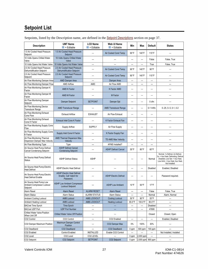
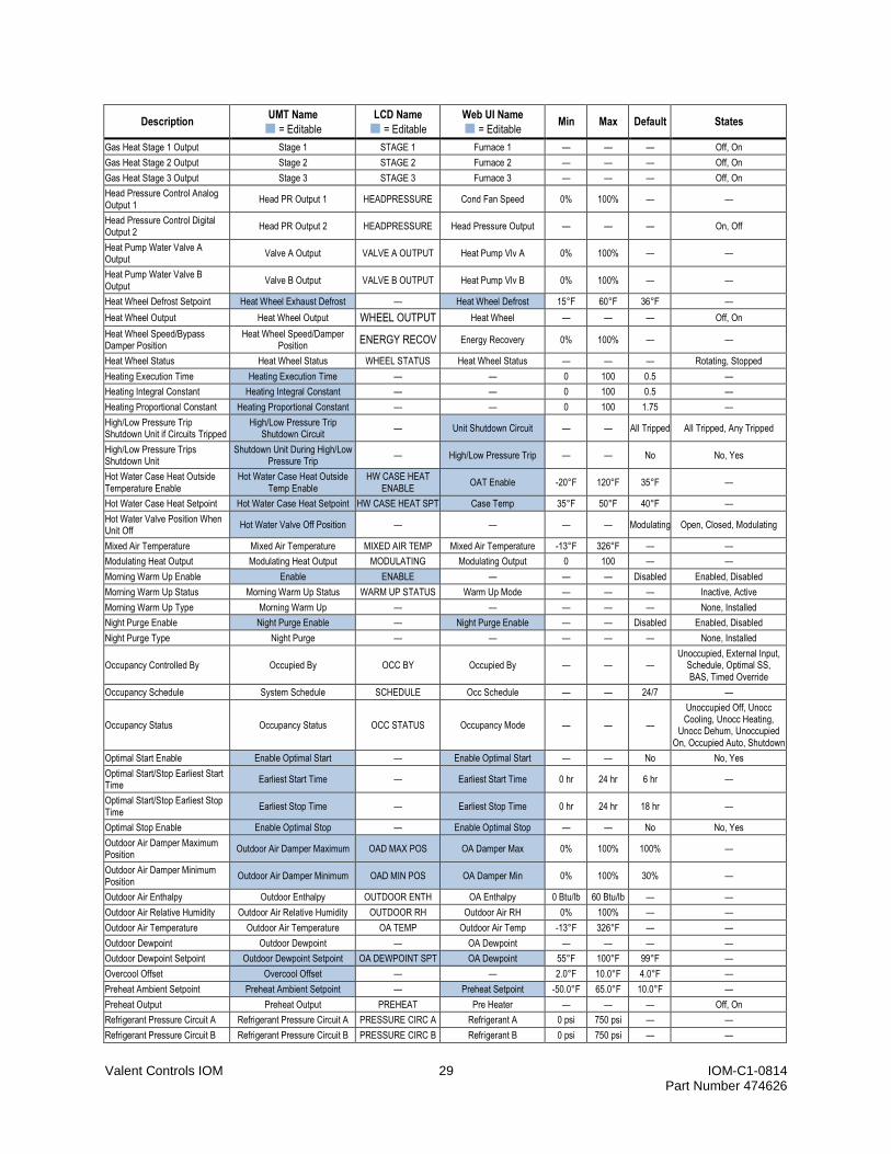
Setpoint List
Setpoints, listed by the Description name, are defined in the Setpoint Descriptions section on page 37.
Description UMT Name
= Editable
LCD Name
= Editable
Web UI Name
= Editable Min Max Default States
1.0 Air Cooled Head Pressure Setpoint
1.0 Air Cooled Head Pressure Setpoint
— Air Cooled Cond Temp 90°F 140°F 115°F —
10 Volts Opens Chilled Water Valve
10 Volts Opens Chilled Water Valve
— — — — False False, True
10 Volts Opens Hot Water Valve 10 Volts Opens Hot Water Valve — — — — True False, True
2.0 Air Cooled Head Pressure Dehumidification Setpoint
2.0 Air Cooled Head Pressure Dehumidification Setpoint
— Air Cooled Cond Temp 90°F 140°F 90°F —
2.0 Air Cooled Head Pressure Setpoint
2.0 Air Cooled Head Pressure Setpoint
— Air Cooled Cond Temp 90°F 140°F 115°F —
Air Flow Monitoring Damper Area AMD Damper Area — Damper Area — — — —
Air Flow Monitoring Damper Flow AMD Airflow AMD Air Flow AMD — — — —
Air Flow Monitoring Damper K Factor
AMD K Factor — K Factor AMD — — — —
Air Flow Monitoring Damper M Factor
AMD M Factor — M Factor — — — —
Air Flow Monitoring Damper Setpoint
Damper Setpoint SETPOINT Damper Spt — — 0 cfm —
Air Flow Monitoring Device Transducer Range
AMD Transducer Range — AMD Transducer Range — — 0-1 InWc 0-.25, 0-.5, 0-1, 0-2
Air Flow Monitoring Exhaust Cone Flow
Exhaust Airflow EXHAUST Air Flow Exhaust — — — —
Air Flow Monitoring Exhaust Cone K Factor
Exhaust Inlet Cone K Factor — K Factor Exhaust Fan — — — —
Air Flow Monitoring Supply Cone Flow
Supply Airflow SUPPLY Air Flow Supply — — — —
Air Flow Monitoring Supply Cone K Factor
Supply Inlet Cone K Factor — K Factor Supply Fan — — — —
Air Flow Monitoring Thermal Dispersion Damper Max Velocity
AMD Thermal Dispersion Max Velocity
— TD AMD Max Velocity — — — —
Air Flow Monitoring Type Type — AFMS Installed? — — — —
Air Source Heat Pump Defrost Cancel Condensing Setpoint
ASHP Defrost Cancel Condensing Setpoint
— ASHP Defrost Cancel 55°F 80°F 60°F —
Air Source Heat Pump Defrost Status
ASHP Defrost Status ASHP — — — Normal
Normal, 1x Defrost, 2x Defrost, 3x -> Aux Heat, Defrosting, Defrost
Disabled, Low Sat -> Aux Heat, Low Amb -> Aux Heat, Aux Heat,
Not Installed
Air Source Heat Pump Electric Heat Defrost
ASHP Electric Heat Defrost — — — — Disabled Enabled, Disabled
Air Source Heat Pump Electric Heat Defrost Enable
ASHP Electric Heat Defrost Enable. Call Valent for
Password. — ASHP Electric Defrost — — — Password required.
Air Source Heat Pump Low Ambient Compressor Lockout Setpoint
ASHP Low Ambient Compressor Lockout Setpoint
— ASHP Low Ambient 10°F 50°F 17°F —
Alarm Reset Alarm Reset ALARM RESET Alarm Reset — — False False, True
Alarm Status Alarm Status ALARM STATUS Alarm Status — — Normal Alarm, Normal
Ambient Cooling Lockout AMB Lockout AMB LOCKOUT Cooling Lockout 50°F 90°F 55°F —
Ambient Heating Lockout AMB Lockout AMB LOCKOUT Heating Lockout 65.0°F 100.0°F 80.0°F —
BACnet Time Synch Time Synch — — — — Disabled —
BACnet UDP Port UDP Port Number — — — — 47808 —
Chilled Water Valve Position When Unit Off
Chilled Water Valve Off Position — — Closed Closed, Open
CO2 Control CO2 Control — CO2 Enabled — — — Enabled, Disabled
CO2 Damper Maximum Position Maximum Damper Control
Position — CO2 Damper Max 0% 100% 30% —
CO2 Deadband CO2 Deadband — CO2 Deadband 0 ppm 500 ppm 100 ppm —
CO2 Enabled Control Enabled INSTALLED Enable CO2 Control — — — Not Installed, Installed
CO2 Level CO2 Level CO2 LEVEL — 0 ppm 2,000 ppm — —
CO2 Setpoint CO2 Setpoint SETPOINT CO2 Setpoint 0 ppm 2,000 ppm 900 ppm —

Valent Controls IOM 28 IOM-C1-0814 Part Number 474626
Description UMT Name
= Editable
LCD Name
= Editable
Web UI Name
= Editable Min Max Default States
Compressor 1 Ambient Lockout Setpoint
Compressor 1 Ambient Lockout Setpoint
— Comp #1 Lockout Setpoint 40.0°F 90.0°F 55°F —
Compressor 1 Output Compressor 1 Output COMP 1 Compressor 1 — — — Off, On
Compressor 2 Ambient Lockout Setpoint
Compressor 2 Ambient Lockout Setpoint
— Comp #2 Lockout Setpoint 40.0°F 90.0°F 55°F —
Compressor 2 Output Compressor 2 Output COMP 2 Compressor 2 — — — Off, On
Compressor 3 Ambient Lockout Setpoint
Compressor 3 Ambient Lockout Setpoint
— Comp #3 Lockout Setpoint 40.0°F 90.0°F 55°F —
Compressor 3 Output Compressor 3 Output COMP 3 Compressor 3 — — — Off, On
Compressor 4 Ambient Lockout Setpoint
Compressor 4 Ambient Lockout Setpoint
— Comp #4 Lockout Setpoint 40.0°F 90.0°F 55°F —
Compressor 4 Output Compressor 4 Output COMP 4 Compressor 4 — — — Off, On
Cooling Execution Time Cooling Execution Time — — 0 100 0.5 —
Cooling Integral Constant Cooling Integral Constant — — 0 100 0.5 —
Cooling Proportional Constant Cooling Proportional Constant — — 0 100 3 —
Damper Configuration Damper Configuration DAMPER CONFIG — — — — 100% OA, Recirc
Damper Output Damper Output OA DAMPER OA Damper Position 0% 100% — —
Damper Remote Control Damper Remote Control — Remote Damper Enabled — — — Enabled, Disabled
Defrost Mode Defrost Mode DEFROST MODE Defrost Mode — — — Normal, Defrost
Dehumidification Priority Dehumidification Has Priority — Dehumidification Priority — — Yes No, Yes
Dehumidification Status Dehumidification Status DEHUM STATUS — — — — False, True
Digital/Chilled Water Output Digital/Chilled Water Output CHW/DIGITAL OUT Digital Output 0% 100% — —
Duct Pressure Duct Pressure PRESSURE Duct Pressure 0 InWc 5 InWc —
Duct Pressure High Limit Setpoint
Duct Pressure High Limit Setpoint
HIGH LIMIT Duct Pressure High Limit 0 InWc 5 InWc 2.50 InWc —
Duct Pressure Setpoint Duct Pressure Setpoint SETPOINT Duct Pressure Setpoint 0 InWc 5 InWc 1.00 InWc —
DX Coil Leaving Temperature DX Coil Leaving Temperature DX COIL TEMP DX Coil Temperature -13°F 326°F — —
DX Coil Low Limit Safety DX Coil Low Limit Safety — Coil Safety Limit 35°F 55°F 46°F —
DX Coil Low Limit Setpoint DX Coil Low Limit Setpoint — Coil Low Limit 35°F 45°F 42°F —
DX Coil Setpoint DX Coil Setpoint DX COIL SETPT DX Coil Setpoint 50°F 80°F 55°F —
Economizer Configuration Economizer Configuration — — — — Outdoor Temper-
ature
Comparative Enthalpy, Outdoor Enthalpy,
Outdoor Temperature
Economizer Enable Setpoint Enthalpy
Economizer Enable Setpoint Enthalpy
ENTHALPY SPT Econ Setpoint Enthalpy 15 Btu/lb 40 Btu/lb 23 Btu/lb —
Economizer Enable Setpoint Temperature
Economizer Enable Setpoint Temperature
DRY BULB SPT Econ Setpoint Temp 50°F 90°F 60°F —
Electric Heat Output Electric Heat Output ELECTRIC Electric Output 0% 100% — —
Enable Compressor 1 Ambient Lockout
Enable Compressor 1 Ambient Lockout
— Comp #1 Lockout Enable — — No No, Yes
Enable Compressor 2 Ambient Lockout
Enable Compressor 2 Ambient Lockout
— Comp #2 Lockout Enable — — No No, Yes
Enable Compressor 3 Ambient Lockout
Enable Compressor 3 Ambient Lockout
— Comp #3 Lockout Enable — — No No, Yes
Enable Compressor 4 Ambient Lockout
Enable Compressor 4 Ambient Lockout
— Comp #4 Lockout Enable — — No No, Yes
Enable Occupancy Auto Mode Enable Occupancy Auto Mode — Enable Occ Auto — — Occ On Occ Auto, Occ On
Enable Winter Ramp Enable Winter Ramp — Winter Ramp — — True False, True
Exhaust Air Temperature Exhaust Temp EXHAUST TEMP Exhaust Temperature -13°F 326°F — —
Exhaust Fan Configuration Configuration — — — — — None, Supply Tracking,
EF Space Pressure, EF Hardwired, EF BAS Control
Exhaust Fan Enable Damper Position
Exhaust Fan Enable Damper Position
EX FAN DAMP POS Exhaust Damper Enable 0% 100% 15% —
Exhaust Fan Maximum Speed Exhaust Fan Max Speed EX FAN MAX SPEED Exhaust Max Speed 25% 100% 100% —
Exhaust Fan Minimum Speed Exhaust Fan Min Speed EX FAN MIN SPEED Exhaust Min Speed 25% 100% 25% —
Exhaust Fan Offset Exhaust Fan Offset EX SPEED OFFSET Exhaust Fan Offset -20% 20% 0% —
Exhaust Fan Output Exhaust Fan Output EXH FAN Exhaust Fan — — — Off, On
Exhaust Fan Reaction Speed Exhaust Fan Reaction Speed EXHAUST REACTION
Exhaust Static Reaction — — Medium Very Slow, Slow, Medium,
Fast, Very Fast
Exhaust Fan Speed Exhaust Fan Speed EXH FAN SPEED Exhaust Fan Speed 0% 100% — —
Exhaust Fan Status Exhaust Fan Status EXH FAN STATUS Exhaust Fan Status — — — Off, On
Flat Pate Defrost Setpoint Flat Plate Exhaust Defrost — Flat Plate Defrost 15°F 60°F 38°F —
Valent Controls IOM 29 IOM-C1-0814 Part Number 474626
Description UMT Name
= Editable
LCD Name
= Editable
Web UI Name
= Editable Min Max Default States
Gas Heat Stage 1 Output Stage 1 STAGE 1 Furnace 1 — — — Off, On
Gas Heat Stage 2 Output Stage 2 STAGE 2 Furnace 2 — — — Off, On
Gas Heat Stage 3 Output Stage 3 STAGE 3 Furnace 3 — — — Off, On
Head Pressure Control Analog Output 1
Head PR Output 1 HEADPRESSURE Cond Fan Speed 0% 100% — —
Head Pressure Control Digital Output 2
Head PR Output 2 HEADPRESSURE Head Pressure Output — — — On, Off
Heat Pump Water Valve A Output
Valve A Output VALVE A OUTPUT Heat Pump Vlv A 0% 100% — —
Heat Pump Water Valve B Output
Valve B Output VALVE B OUTPUT Heat Pump Vlv B 0% 100% — —
Heat Wheel Defrost Setpoint Heat Wheel Exhaust Defrost — Heat Wheel Defrost 15°F 60°F 36°F —
Heat Wheel Output Heat Wheel Output WHEEL OUTPUT Heat Wheel — — — Off, On
Heat Wheel Speed/Bypass Damper Position
Heat Wheel Speed/Damper Position
ENERGY RECOV Energy Recovery 0% 100% — —
Heat Wheel Status Heat Wheel Status WHEEL STATUS Heat Wheel Status — — — Rotating, Stopped
Heating Execution Time Heating Execution Time — — 0 100 0.5 —
Heating Integral Constant Heating Integral Constant — — 0 100 0.5 —
Heating Proportional Constant Heating Proportional Constant — — 0 100 1.75 —
High/Low Pressure Trip Shutdown Unit if Circuits Tripped
High/Low Pressure Trip Shutdown Circuit
— Unit Shutdown Circuit — — All Tripped All Tripped, Any Tripped
High/Low Pressure Trips Shutdown Unit
Shutdown Unit During High/Low Pressure Trip
— High/Low Pressure Trip — — No No, Yes
Hot Water Case Heat Outside Temperature Enable
Hot Water Case Heat Outside Temp Enable
HW CASE HEAT ENABLE
OAT Enable -20°F 120°F 35°F —
Hot Water Case Heat Setpoint Hot Water Case Heat Setpoint HW CASE HEAT SPT Case Temp 35°F 50°F 40°F —
Hot Water Valve Position When Unit Off
Hot Water Valve Off Position — — — — Modulating Open, Closed, Modulating
Mixed Air Temperature Mixed Air Temperature MIXED AIR TEMP Mixed Air Temperature -13°F 326°F — —
Modulating Heat Output Modulating Heat Output MODULATING Modulating Output 0 100 — —
Morning Warm Up Enable Enable ENABLE — — — Disabled Enabled, Disabled
Morning Warm Up Status Morning Warm Up Status WARM UP STATUS Warm Up Mode — — — Inactive, Active
Morning Warm Up Type Morning Warm Up — — — — — None, Installed
Night Purge Enable Night Purge Enable — Night Purge Enable — — Disabled Enabled, Disabled
Night Purge Type Night Purge — — — — — None, Installed
Occupancy Controlled By Occupied By OCC BY Occupied By — — — Unoccupied, External Input,
Schedule, Optimal SS, BAS, Timed Override
Occupancy Schedule System Schedule SCHEDULE Occ Schedule — — 24/7 —
Occupancy Status Occupancy Status OCC STATUS Occupancy Mode — — —
Unoccupied Off, Unocc Cooling, Unocc Heating,
Unocc Dehum, Unoccupied On, Occupied Auto, Shutdown
Optimal Start Enable Enable Optimal Start — Enable Optimal Start — — No No, Yes
Optimal Start/Stop Earliest Start Time
Earliest Start Time — Earliest Start Time 0 hr 24 hr 6 hr —
Optimal Start/Stop Earliest Stop Time
Earliest Stop Time — Earliest Stop Time 0 hr 24 hr 18 hr —
Optimal Stop Enable Enable Optimal Stop — Enable Optimal Stop — — No No, Yes
Outdoor Air Damper Maximum Position
Outdoor Air Damper Maximum OAD MAX POS OA Damper Max 0% 100% 100% —
Outdoor Air Damper Minimum Position
Outdoor Air Damper Minimum OAD MIN POS OA Damper Min 0% 100% 30% —
Outdoor Air Enthalpy Outdoor Enthalpy OUTDOOR ENTH OA Enthalpy 0 Btu/lb 60 Btu/lb — —
Outdoor Air Relative Humidity Outdoor Air Relative Humidity OUTDOOR RH Outdoor Air RH 0% 100% — —
Outdoor Air Temperature Outdoor Air Temperature OA TEMP Outdoor Air Temp -13°F 326°F — —
Outdoor Dewpoint Outdoor Dewpoint — OA Dewpoint — — — —
Outdoor Dewpoint Setpoint Outdoor Dewpoint Setpoint OA DEWPOINT SPT OA Dewpoint 55°F 100°F 99°F —
Overcool Offset Overcool Offset — — 2.0°F 10.0°F 4.0°F —
Preheat Ambient Setpoint Preheat Ambient Setpoint — Preheat Setpoint -50.0°F 65.0°F 10.0°F —
Preheat Output Preheat Output PREHEAT Pre Heater — — — Off, On
Refrigerant Pressure Circuit A Refrigerant Pressure Circuit A PRESSURE CIRC A Refrigerant A 0 psi 750 psi — —
Refrigerant Pressure Circuit B Refrigerant Pressure Circuit B PRESSURE CIRC B Refrigerant B 0 psi 750 psi — —

Valent Controls IOM 30 IOM-C1-0814 Part Number 474626
Description UMT Name
= Editable
LCD Name
= Editable
Web UI Name
= Editable Min Max Default States
Space Dewpoint Space Dewpoint — Space Dewpoint — — — —
Space Dewpoint Dehumidification Disable Setpoint
Space Dewpoint Dehumidification Cutout
— Space DPT Disable 0.0°F 70.0°F 45.0°F —
Space Enthalpy Space Enthalpy SPACE ENTH Space Enthalpy 0 Btu/lb 60 Btu/lb — —
Space Pressure High Limit Setpoint
Space Pressure High Limit Setpoint
HIGH LIMIT Space Pressure High Lim 0.000 InWc
+0.500 InWc
+0.200 InWc
—
Space Relative Humidity Space Relative Humidity SPACE RH Space RH 0% 100% — —
Space Relative Humidity Occupied Deadband Setpoint
Occupied Space Humidity Low Deadband
— — 0% 15% 5% —
Space Relative Humidity Setpoint Space Relative Humidity Setpoint SPACE RH SPT Space RH Setpoint 0% 100% 55% —
Space Relative Humidity Unoccupied Deadband Setpoint
Unoccupied Space Humidity Low Deadband
— — 0% 15% 5% —
Space Static Pressure Space Pressure PRESSURE Space Pressure -0.5 InWc +0.5 InWc — —
Space Static Pressure Setpoint Setpoint SETPOINT Space Pressure Setpoint -0.500 InWc
+0.500 InWc
+0.050 InWc
—
Space Temperature Space Temperature SPACE TEMP Space Temperature -13°F 326°F — —
Space Temperature Cooling Setpoint
— — Space Cooling Setpoint — — — —
Space Temperature Heating Setpoint
— — Space Heating Setpoint — — — —
Space Temperature Setpoint Space Temperature Setpoint SPACE SETPT Space Temp Setpoint 60°F 90°F 74°F —
Space Temperature Setpoint Offset
Space Temperature Setpoint Offset
SPACE OFFSET Space Temp Offset 0.0°F 20.0°F 0.0°F —
Supply Air Cooling High Deadband Setpoint
Supply Air Cooling High Deadband
— Supply Deadband 0.0°F 8.0°F 0.0°F —
Supply Air Cooling Low Deadband Setpoint
Supply Air Cooling Low Deadband
— Supply Deadband 0.0°F 8.0°F 0.0°F —
Supply Air Deadband Enable Setpoint
Temperature Control PID Deadband Enable
— Deadband Enable — — Disable Enabled, Disabled
Supply Air Heating High Deadband Setpoint
Supply Air Heating High Deadband
— Supply Deadband 0.0°F 8.0°F 0.0°F —
Supply Air Heating Low Deadband Setpoint
Supply Air Heating Low Deadband
— Supply Deadband 0.0°F 8.0°F 0.0°F —
Supply Air Temperature Control Supply Air Temperature Control SUPPLY CONTROL — — — Auto Auto, Yes
Supply Air Temperature High Limit
Supply Temperature High Limit — Supply High Limit 90°F 120°F 120°F —
Supply Air Temperature High Limit Alarm Delay
Supply High Temp Alarm Delay — — 3 min 15 min 3 min —
Supply Air Temperature Low Limit
Supply Temperature Low Limit — Supply Low Limit 30°F 50°F 35°F —
Supply Air Temperature Maximum Cooling Setpoint
Supply Air Maximum Cooling Setpoint
SUPPLY MAX COOL Supply Max Cool Setpoint 70.0°F 95.0°F 95.0°F —
Supply Air Temperature Maximum Heating Setpoint
Supply Air Maximum Heating Setpoint
SUPPLY MAX HEAT Supply Max Heat Setpoint 70.0°F 95.0°F 95.0°F —
Supply Air Temperature Minimum Cooling Setpoint
Supply Air Minimum Cooling Setpoint
SUPPLY MIN COOL Supply Min Cool Setpoint 50.0°F 70.0°F 55.0°F —
Supply Air Temperature Minimum Heating Setpoint
Supply Air Minimum Heating Setpoint
SUPPLY MIN HEAT Supply Min Heat Setpoint 50.0°F 70.0°F 65.0°F —
Supply Air Temperature Setpoint Supply Air Temperature Setpoint SUPPLY SETPT Supply Temp Setpoint 50°F 95°F 70°F —
Supply Fan Maximum Speed Spt Supply Fan Max Speed Setpoint SUP FAN MAX Supply Fan Max Speed 50% 100% 100% —
Supply Fan Minimum Speed Setpoint
Supply Fan Min Speed SUP FAN MIN Supply Fan Min Speed 50% 100% 50% —
Supply Fan Output Supply Fan Output SUPPLY FAN Supply Fan — — — Off, On
Supply Fan Reaction Speed (Duct Pressure)
Supply Fan Reaction Speed SUPPLY REACTION — — — Medium Very Slow, Slow, Medium,
Fast, Very Fast
Supply Fan Reaction Speed (Space Pressure)
Supply Fan Reaction Speed SUPPLY REACTION — — — Medium Very Slow, Slow, Medium,
Fast, Very Fast
Supply Fan Speed Supply Fan Speed SUP FAN SPEED Supply Fan Speed 0% 100% — —
Supply Fan Status Supply Fan Status SUP FAN STATUS Supply Fan Status — — — Off, On
Supply Setpoint Calculated Supply Setpoint Calculated SUPPLY CALC Calculated Supply Spt — — — —
Supply Temperature Supply Temperature SUPPLY TEMP Supply Temperature — — — —
System Enable System Enable SYSTEM ENABLE System Enable — — Off Off, On
Timed Override Duration Timed Override Duration — TOV Duration 0 min 240 min 120 min —

Valent Controls IOM 31 IOM-C1-0814 Part Number 474626
Description UMT Name
= Editable
LCD Name
= Editable
Web UI Name
= Editable Min Max Default States
Unit Schedule Unit Schedule SCHEDULING — — — 24/7 —
Unoccupied Outdoor Air Damper Minimum
Unoccupied Outdoor Air Damper Minimum
— Unocc OA Damp Min 0% 100% 0% —
Unoccupied Space Cooling Setpoint
Unoccupied Space Cooling Setpoint
UNOCC COOL Unocc Cool Setpoint 75°F 85°F 80°F —
Unoccupied Space Heating Setpoint
Unoccupied Space Heating Setpoint
UNOCC HEATING Unocc Heat Setpoint 55°F 70°F 60°F —
Unoccupied Space Relative Humidity Setpoint
Unoccupied Space Humidity Setpoint
— Space Unocc RH Spt 0% 100% 68% —
Unoccupied Supply Fan Offset Unoccupied Supply Fan Speed
Offset — — 0% 50% 0% —
Water Source Heat Pump Cold Start Duration
WSHP Cold Start Duration — WSHP Cold Start 0 sec 300 sec 60 sec —
Water Source Heat Pump Cold Start Enable Temperature
WSHP Cold Start Enable Temp — WSHP Cold Start 0°F 60°F 30°F —
Water Source Heat Pump Compressor Off Water Valve
Position
WSHP Compressor Off Water Valve Position
COMP OFFVLVPOS WSHP Valve Off 0% 100% 100% —
Water Source Heat Pump Condenser Temperature Setpoint
WSHP Condenser Temperature Setpoint
— WSHP Cond Temp 90°F 120°F 115°F —
Water Source Heat Pump Suction Temp Low Limit
WSHP Suction Temp Low Limit Safety
WSHP SUC LOWLIM WSHP Suction Safety 0°F 40°F 25°F —
Water Source Heat Pump Water Valve Max Closed Position Setpt
WSHP Valve Max Closed Position
— — 50% 100% 85% —
Winter Ramp Control Type Winter Ramp Control Type — Winter Control — — Supply
Fan Supply Fan, Damper
Winter Ramp Type In Control Winter Ramp Type In Control — — — — — —
BACnet Setpoint List
Setpoints, listed by the Description name, are defined in the Setpoint Descriptions section on page 37.
* BAS reported sensor values: Sensor readings as relayed by a building management system override any hardwired sensors connected to the unit.
** All editable BACnet points can be written to at the following priorities: in2, in3, in4, in5, in7, in8, in9, in10, in11, in12, in13, in14, in15, in16.
Description =Editable** Object Name Object Type Instance
Supply Temperature Supply Temp Analog Value 1
Space Temperature Space Temp Analog Value 2
DX Coil Leaving Temperature DXCoilTemp Analog Value 3
Space Relative Humidity SpaceRH Analog Value 4
Indoor Enthalpy Indoor Enthalpy Analog Value 5
Space Dewpoint Space Dewpoint Analog Value 6
Space CO2 SpaceCO2 Analog Value 7
Outdoor Air Temperature OutdoorTemp Analog Value 8
Outdoor Relative Humidity OutdoorRH Analog Value 9
Outdoor Enthalpy Outdoor Enthalpy Analog Value 10
Outdoor Air Dewpoint OA Dewpoint Analog Value 11
Exhaust Temperature ExhaustTemp Analog Value 12
Mixed Air Temperature MixedAirTemp Analog Value 13
Duct Static Pressure DuctStaticPressure Analog Value 14
Space Static Pressure SpaceStaticPressure Analog Value 15
Circuit A Refrigerant Pressure CircuitA_Pressure Analog Value 16
Circuit B Refrigerant Pressure CircuitB_Pressure Analog Value 17
Air Flow Monitoring Station CFM AFMS CFM Analog Value 18
Supply Fan Speed SupplyFanSpeed Analog Value 19

Valent Controls IOM 32 IOM-C1-0814 Part Number 474626
Description =Editable** Object Name Object Type Instance
Exhaust Fan Speed ExFanSpeed Analog Value 20
Outdoor Damper Position OutdoorDamperPos Analog Value 21
Hot Gas Reheat Percentage HotGasReheatPct Analog Value 22
Digital Scroll Compressor Percentage DigitalScrollPct Analog Value 23
Chilled Water Valve Position ChilledWaterValvePos Analog Value 24
Modulating Heat Percentage, Primary HeatPrimaryPct Analog Value 25
Modulating Heat Percentage, Secondary HeatSecondaryPct Analog Value 26
Head Pressure Analog Output Status HeadPressureAO Analog Value 27
Heat Pump Water Valve A Percentage HP_WaterValveA Analog Value 28
Heat Pump Water Valve B Percentage HP_WaterValveB Analog Value 29
Space Temperature Setpoint from BAS * Space Temp Setpoint Analog Value 30
Supply Temperature Setpoint from BAS * Supply Temp Setpoint Analog Value 31
Space Humidity Setpoint from BAS * Space Humidity Setpoint Analog Value 32
CO2 Level Setpoint from BAS * CO2 Setpoint Analog Value 34
Supply Duct Static Pressure Setpoint from BAS * Supply Duct Pressure Setpoint Analog Value 35
Space Static Pressure Setpoint from BAS * Space Pressure Setpoint Analog Value 36
BAS Reported Space Temperature * Space Temp BAS Analog Value 37
BAS Reported Space Relative Humidity * Space RH BAS Analog Value 38
BAS Reported Outdoor Relative Humidity * Outdoor RH BAS Analog Value 39
BAS Reported Outdoor Air Temperature * Outdoor Temp BAS Analog Value 40
BAS Reported Space Static Pressure * Space Static BAS Analog Value 41
BAS Reported Supply Duct Static Pressure * Duct Static BAS Analog Value 42
BAS Reported Space CO2 Level * CO2 BAS Analog Value 43
Exhaust Fan BAS Speed Command * ExhaustSpeedBAS Analog Value 44
BAS Remote Damper Signal * OA_DamperPOS_BAS Analog Value 45
Supply Fan BAS Speed Command * Supply Fan BAS Speed Analog Value 46
Air Flow Monitoring Station CFM 2 AFMS CFM 2 Analog Value 47
Energy Recovery Control Output Energy Recovery Analog Value 48
Space Unoccupied Cooling Setpoint Space Unoccupied Cooling Setpoint Analog Value 49
Space Unoccupied Heating Setpoint Space Unoccupied Heating
Setpoint Analog Value 50
Space Unoccupied Humidity Setpoint Space Unoccupied Humidity
Setpoint Analog Value 51
Space Temperature Heating Setpoint SpaceHeatingSetpoint Analog Value 52
Space Temperature Cooling Setpoint SpaceCoolingSetpoint Analog Value 53
Space Temperature Setpoint Offset SpaceTempSptOffset Analog Value 54
Air Flow Monitoring Exhaust Cone Flow Exhaust CFM Analog Value 55
System Start Command SystemStart Binary Value 1
Shutdown Input Status RunStopStatus Binary Value 2
Supply Fan Status SupplyFanStatus Binary Value 3
Exhaust Fan Status ExFanStatus Binary Value 4
Heat Wheel Status HeatWheelStatus Binary Value 5
Compressor 1 Status Compr1Status Binary Value 6
Compressor 2 Status Compr2Status Binary Value 7
Compressor 3 Status Compr3Status Binary Value 8
Compressor 4 Status Compr4Status Binary Value 9
Gas Heat Enable, Stage 1 GasHeatEnaStg1 Binary Value 10
Gas Heat Enable, Stage 2 GasHeatEnaStg2 Binary Value 11
Gas Heat Enable, Stage 3 GasHeatEnaStg3 Binary Value 12
Head Pressure Digital Output Status HeadPressureDO Binary Value 13

Valent Controls IOM 33 IOM-C1-0814 Part Number 474626
Description =Editable** Object Name Object Type Instance
Reversing Valve Position RevValve Binary Value 14
Enables BAS to Control Occupancy * BAS_Occ_Enable Binary Value 15
BAS Occupancy Command * BAS_Occ_Command Binary Value 16
BAS Cooling Disable Request * Cooling Disable Request Binary Value 17
BAS Heating Disable Request * Heating Disable Request Binary Value 18
BAS System Emergency Shutdown Command * System Shutdown BAS Binary Value 19
Alarm Reset AlarmReset Binary Value 20
System Alarm Status Alarm Status Binary Value 21
Shutdown Input Alarm Shutdown Input Alarm Binary Value 22
Supply Fan Alarm Supply Fan Alarm Binary Value 23
Exhaust Fan Alarm ExhaustFanAlarm Binary Value 24
Damper End Switch Alarm EndSwitchAlarm Binary Value 25
Circuit A High Low Pressure Alarm HPC_LPC_A_Alarm Binary Value 26
Circuit B High Low Pressure Alarm HPC_LPC_B_Alarm Binary Value 27
Refrigerant Pressure Transducer Circuit A Alarm RefPressureAAlarm Binary Value 28
Refrigerant Pressure Transducer Circuit B Alarm RefPressureBAlarm Binary Value 29
Supply Temperature Sensor Alarm SupplyTempSensorAlarm Binary Value 30
Exhaust Temperature Sensor Alarm ExhaustTempSensorAlarm Binary Value 32
Mixed Air Temperature Sensor Alarm MixedTempSensorAlarm Binary Value 33
Outdoor Air Relative Humidity Sensor Alarm OA_RH_Sensor_Alarm Binary Value 34
Outdoor Air Temperature Sensor Alarm OASensorAlarm Binary Value 35
Space High Static Pressure Alarm SpaceStaticAlarm Binary Value 36
Supply Duct High Static Alarm DuctStaticAlarm Binary Value 37
Heat Wheel Rotation Sensor Alarm HWSensorAlarm Binary Value 38
CO2 Sensor Alarm CO2SensorAlarm Binary Value 39
Clogged Filter Alarm FilterAlarm Binary Value 40
Supply Temperature Low Limit Alarm SupplyLowLimitAlarm Binary Value 41
Supply Temperature High Limit Alarm SupplyHighLimitAlarm Binary Value 42
Space Temperature Sensor Alarm SpaceTempSensorAlarm Binary Value 43
Energy Recovery Defrost Mode. True = Defrost Energy Recovery Defrost Binary Value 45
Allows BAS to Override the supply fan signal. * BAS SF Override Enable Binary Value 46
Allows BAS to Override the exhaust fan signal. * BAS EF Override Enable Binary Value 47
Allows BAS to Override the outdoor air damper signal. *
BAS OAD Override Enable Binary Value 48
WSHP Refrigerant Low Pressure Alarm WSHP Ref Low Pressure Alarm Binary Value 49
Freezestat Alarm FreezestatAlarm Binary Value 50
Occupancy Mode 1.Unocc Off 2.Unocc Cooling 3.Unocc Heating On 4.Unocc Dehum 5.Occupied On 6.Occupied Auto 7.Shutdown
OccupancyMode Multi State Value 1
1.Fan Only 2.Economizing 3.Energy Recovery 4.Cooling 5.Cooling w/Energy Recovery 6.Heating 7.Heating w/Energy Recovery 8.Dehumidifying 9.Off 10.Shutdown Delay
Unit Mode Multi State Value 2
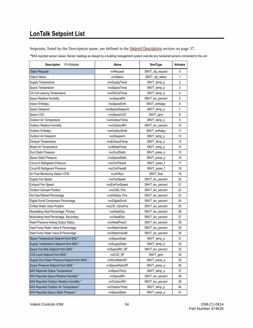
Valent Controls IOM 34 IOM-C1-0814 Part Number 474626
LonTalk Setpoint List
Setpoints, listed by the Description name, are defined in the Setpoint Descriptions section on page 37.
*BAS reported sensor values: Sensor readings as relayed by a building management system override any hardwired sensors connected to the unit.
Description =Editable Name SnvtType NvIndex
Object Request nviRequest SNVT_obj_request 0
Object Status nvoStatus SNVT_obj_status 1
Supply Temperature nvoSupplyTemp SNVT_temp_p 2
Space Temperature nvoSpaceTemp SNVT_temp_p 3
DX Coil Leaving Temperature nvoDXCoilTemp SNVT_temp_p 4
Space Relative Humidity nvoSpaceRH SNVT_lev_percent 5
Indoor Enthalpy nvoSpaceEnth SNVT_enthalpy 6
Space Dewpoint nvoSpaceDewpoint SNVT_temp_p 7
Space CO2 nvoSpaceCO2 SNVT_ppm 8
Outdoor Air Temperature nvoOutdoorTemp SNVT_temp_p 9
Outdoor Relative Humidity nvoOutdoorRH SNVT_lev_percent 10
Outdoor Enthalpy nvoOutdoorEnth SNVT_enthalpy 11
Outdoor Air Dewpoint nvoDewpoint SNVT_temp_p 12
Exhaust Temperature nvoExhaustTemp SNVT_temp_p 13
Mixed Air Temperature nvoMixedTemp SNVT_temp_p 14
Duct Static Pressure nvoDuctStatic SNVT_press_p 15
Space Static Pressure nvoSpaceStatic SNVT_press_p 16
Circuit A Refrigerant Pressure nvoCircPressA SNVT_press_f 17
Circuit B Refrigerant Pressure nvoCircPressB SNVT_press_f 18
Air Flow Monitoring Station CFM nvoAirflow SNVT_flow 19
Supply Fan Speed nvoFanSpeed SNVT_lev_percent 20
Exhaust Fan Speed nvoExhFanSpeed SNVT_lev_percent 21
Outdoor Damper Position nvoOAD_Pos SNVT_lev_percent 22
Hot Gas Reheat Percentage nvoHotGas_Pos SNVT_lev_percent 23
Digital Scroll Compressor Percentage nvoDigitalScroll SNVT_lev_percent 24
Chilled Water Valve Position nvoCW_ValvePos SNVT_lev_percent 25
Modulating Heat Percentage, Primary nvoHeatGas SNVT_lev_percent 26
Modulating Heat Percentage, Secondary nvoHeatElec SNVT_lev_percent 27
Head Pressure Analog Output Status nvoHeadPress1 SNVT_lev_percent 28
Heat Pump Water Valve A Percentage nvoWaterValveA SNVT_lev_percent 29
Heat Pump Water Valve B Percentage nvoWaterValveB SNVT_lev_percent 30
Space Temperature Setpoint from BAS * nviSpaceSetpt SNVT_temp_p 31
Supply Temperature Setpoint from BAS * nviSupplySetpt SNVT_temp_p 32
Space Humidity Setpoint from BAS * nviSpaceRH_SP SNVT_lev_percent 33
CO2 Level Setpoint from BAS * nviCO2_SP SNVT_ppm 34
Supply Duct Static Pressure Setpoint from BAS * nviDuctStaticSP SNVT_press_p 35
Space Pressure Setpoint from BAS * nviSpaceStaticSP SNVT_press_p 36
BAS Reported Space Temperature * nviSpaceTemp SNVT_temp_p 37
BAS Reported Space Relative Humidity * nviSpaceRH SNVT_lev_percent 38
BAS Reported Outdoor Relative Humidity * nviOutdoorRH SNVT_lev_percent 39
BAS Reported Outdoor Air Temperature * nviOutdoorTemp SNVT_temp_p 40
BAS Reported Space Static Pressure * nviSpaceStatic SNVT_press_p 41

Valent Controls IOM 35 IOM-C1-0814 Part Number 474626
Description =Editable Name SnvtType NvIndex
BAS Reported Supply Duct Static Pressure * nviDuctStatic SNVT_press_p 42
BAS Reported Space CO2 Level * nviCO2 SNVT_ppm 43
Exhaust Fan BAS Speed Command * nviExhFanSpeed SNVT_lev_percent 44
BAS Remote Damper Signal * nviOAD_Pos SNVT_lev_percent 45
Supply Fan BAS Speed Command * nviFanSpeed SNVT_lev_percent 46
System Start Command nvoUnitStart SNVT_switch 47
Shutdown Input Status nvoShutdown SNVT_switch 48
Supply Fan Status nvoFanStatus SNVT_switch 49
Exhaust Fan Status nvoExhFanStatus SNVT_switch 50
Heat Wheel Status nvoWheelStatus SNVT_switch 51
Compressor 1 Status nvoCompr1Status SNVT_switch 52
Compressor 2 Status nvoCompr2Status SNVT_switch 53
Compressor 3 Status nvoCompr3Status SNVT_switch 54
Compressor 4 Status nvoCompr4Status SNVT_switch 55
Gas Heat Enable, Stage 1 nvoGasStage1 SNVT_switch 56
Gas Heat Enable, Stage 2 nvoGasStage2 SNVT_switch 57
Gas Heat Enable, Stage 3 nvoGasStage3 SNVT_switch 58
Head Pressure Digital Output Status nvoHeadPress2 SNVT_switch 59
Reversing Valve Position nvoRevValve SNVT_switch 60
Enables BAS to Control Occupancy * nviBAS_OccEnable SNVT_switch 61
BAS Occupancy Command * nviBAS_OccCmd SNVT_switch 62
BAS Cooling Disable Request * nviCoolDisable SNVT_switch 63
BAS Heating Disable Request * nviHeatDisable SNVT_switch 64
BAS System Emergency Shutdown Command * nviShutdown SNVT_switch 65
Alarm Reset nviAlarmReset SNVT_switch 66
System Alarm Status nvoAlarmStatus SNVT_switch 67
Shutdown Input Alarm nvoAlmShutdown SNVT_switch 68
Supply Fan Alarm nvoAlmFan SNVT_switch 69
Exhaust Fan Alarm nvoAlmExhFan SNVT_switch 70
Damper End Switch Alarm nvoAlmEndSwitch SNVT_switch 71
Circuit A High Low Pressure Alarm nvoAlmCircA SNVT_switch 72
Circuit B High Low Pressure Alarm nvoAlmCircB SNVT_switch 73
Refrigerant Pressure Transducer Circuit A Alarm nvoAlmCircPressA SNVT_switch 74
Refrigerant Pressure Transducer Circuit B Alarm nvoAlmCircPressB SNVT_switch 75
Supply Temperature Sensor Alarm nvoAlmSupplyTmp SNVT_switch 76
Space Temperature Sensor Alarm nvoAlmSpaceTmp SNVT_switch 77
Exhaust Temperature Sensor Alarm nvoAlmExhTmp SNVT_switch 78
Mixed Air Temperature Sensor Alarm nvoAlmMixedTmp SNVT_switch 79
Outdoor Air Relative Humidity Sensor Alarm nvoAlmOA_RH SNVT_switch 80
Outdoor Air Temperature Sensor Alarm nvoAlmOA_Temp SNVT_switch 81
Space High Static Pressure Alarm nvoAlmSpcStatic SNVT_switch 82
Supply Duct High Static Alarm nvoAlmDuctStatic SNVT_switch 83
Heat Wheel Rotation Sensor Alarm nvoAlmHWRotation SNVT_switch 84
CO2 Sensor Alarm nvoAlmCO2 SNVT_switch 85
Clogged Filter Alarm nvoAlmFilters SNVT_switch 86
Supply Temperature Low Limit Alarm nvoAlmSupLow SNVT_switch 87
Supply Temperature High Limit Alarm nvoAlmSupHigh SNVT_switch 88
1.Fan Only 2.Economizing 3.Energy Recovery nvoOccStatus SNVT_str_asc 89

Valent Controls IOM 36 IOM-C1-0814 Part Number 474626
Description =Editable Name SnvtType NvIndex
4.Cooling 5.Cooling w/Energy Recovery 6.Heating 7.Heating w/Energy Recovery 8.Dehumidifying 9.Off 10.Shutdown Delay
Air Flow Monitoring Station CFM 2 nvoAirflow2 SNVT_flow 90
Energy Recovery Control Output nvoEnergyRecovery SNVT_lev_percent 91
Energy Recovery Defrost Mode. True = Defrost nvoDefrostMode SNVT_switch 92
Allows BAS to override the supply fan signal. * nviBAS_SF_Ovrd SNVT_switch 93
Allows BAS to override the exhaust fan signal. * nviBAS_EF_Ovrd SNVT_switch 94
Allows BAS to override the outdoor air damper signal. *
nviBAS_OAD_Ovrd SNVT_switch 95
WSHP Refrigerant Low Pressure Alarm nvoAlmWSHPLowPSI SNVT_switch 96
Space Unoccupied Cooling Setpoint nviUnocCoolSpt SNVT_temp_p 97
Space Unoccupied Heating Setpoint nviUnocHeatSpt SNVT_temp_p 98
Space Unoccupied Humidity Setpoint nviUnocHumidSpt SNVT_lev_percent 99
Occupancy Mode 1.Unocc Off 2.Unocc Cooling 3.Unocc Heating On 4.Unocc Dehum 5.Occupied On 6.Occupied Auto 7.Shutdown
nvoUnitMode SNVT_str_asc 100
Freezestat Alarm nvoAlmFreezestat SNVT_switch 101
Space Temperature Setpoint Offset nviSpaceOffset SNVT_temp_diff_p 102
Space Temperature Cooling Setpoint nvoSpaceCoolSpt SNVT_temp_p 103
Space Temperature Heating Setpoint nvoSpaceHeatSpt SNVT_temp_p 104
Air Flow Monitoring Exhaust Cone Flow nvoExhaustCFM SNVT_flow 105

Valent Controls IOM 37 IOM-C1-0814 Part Number 474626
Setpoint Descriptions
This section contains definitions for all setpoints
available on the LCD, UMT, Web UI, and also via
BACnet and LonTalk. Setpoints are listed here by
their descriptions. Setpoints may have different
names on different displays. Refer to the following
for display names and setpoint parameters:
Setpoint List, page 27.
BACnet Setpoint List, page 31.
LonTalk Setpoint List, page 34.
1.0 Air Cooled Head Pressure Setpoint
Sets the saturated condensing temperature target for
the Active Head Pressure Control (condenser fan)
control loop. Applies to air-cooled units equipped
with Active Head Pressure Control 1.0 and running in
Cooling or Dehumidification mode. Consult the
factory before adjusting this setpoint.
10 Volts Opens Chilled Water Valve
When set to True, the control system assumes that a
direct acting water valve is installed and 10VDC
output = full flow. If set to False, the control system
assumes a reverse acting water valve is installed.
10 Volts Opens Hot Water Valve
When set to True, the control system assumes that a
direct acting water valve is installed and 10VDC
output = full flow. If set to False, the control system
assumes a reverse acting water valve is installed.
2.0 Air Cooled Head Pressure Dehumidification Setpoint
Sets the saturated condensing temperature target for
the Active Head Pressure Control (condenser fan)
control loop. Applies to air-cooled units equipped
with Active Head Pressure Control 2.0 and running in
Dehumidification mode. Consult the factory before
adjusting this setpoint.
2.0 Air Cooled Head Pressure Setpoint
Sets the saturated condensing temperature target for
the Active Head Pressure Control (condenser fan)
control loop. Applies to air-cooled units equipped
with Active Head Pressure Control 2.0 and running in
Cooling mode. Consult the factory before adjusting
this setpoint.
Air Flow Monitoring Damper Area
Consult the factory before adjusting this setpoint.
Air Flow Monitoring Damper Flow
The airflow, in CFM, as measured by the airflow
monitoring damper (AMD), if installed in the outdoor
air stream.
Air Flow Monitoring Damper K Factor
Consult the factory before adjusting this setpoint.
Air Flow Monitoring Damper M Factor
Consult the factory before adjusting this setpoint.
Air Flow Monitoring Damper Setpoint
The rate of air flow, in CFM, that the air flow
monitoring damper maintains when the unit is
occupied.
Air Flow Monitoring Device Transducer Range
Consult the factory before adjusting this setpoint.
Air Flow Monitoring Exhaust Cone Flow
The exhaust air flow, in CFM, as measured by a fan
inlet cone air flow monitoring station, if installed.
Air Flow Monitoring Exhaust Cone K Factor
Consult the factory before adjusting this setpoint.
Air Flow Monitoring Supply Cone Flow
The air flow, in CFM, as measured by a fan inlet
cone air flow monitoring station, if installed.
Air Flow Monitoring Supply Cone K Factor
Consult the factory before adjusting this setpoint.
Air Flow Monitoring Thermal Dispersion Damper Max Velocity
Consult the factory before adjusting this setpoint.
Air Flow Monitoring Type
Indicates if an air flow monitoring station is installed,
and the type of station.
Air Source Heat Pump Defrost Cancel Condensing Setpoint
When the condensing temperature reaches this
setpoint, the unit will cancel the defrost mode and
resume normal operation.

Valent Controls IOM 38 IOM-C1-0814 Part Number 474626
Air Source Heat Pump Defrost Status
Indicates whether an ASHP unit in heating mode is
actively defrosting the outside coil by changing from
Normal to Defrosting, and also indicates which
portion of the defrost logic, if any, is active.
If the unit is configured to operate without defrost
mode, this point displays Defrost Disabled.
The number of defrost cycles in the last hour is
indicated by: 1x Defrost, 2x Defrost.
If the unit has switched to an auxiliary heat source,
this point displays the reason why:
3x -> Aux Heat: Third Defrost cycle in a one
hour interval.
Aux Heat: Defrost requested, but unit is
configured to operate without defrost mode.
Low Sat -> Aux Heat: Failure to maintain
requested supply temperature.
Low Amb -> Aux Heat: Ambient conditions too
cold to run as an Air Source Heat Pump.
If the unit is not an Air Source Heat Pump, this point
displays Not Installed.
Air Source Heat Pump Electric Heat Defrost
Indicates whether the Electric Heater is allowed to
operate during ASHP defrost mode.
Air Source Heat Pump Electric Heat Defrost Enable
A password is required to control this point. Contact
Valent for password.
Air Source Heat Pump Low Ambient Compressor Lockout Setpoint
If the outdoor air temperature is below this setpoint,
the compressors are locked out from heating and
cooling.
Alarm Reset
This point resets all of the unit alarms.
Alarm Status
The status of the controller’s alarm output (Digital
Output 9). Digital Output 9 on the 34-point module
closes and the associated LED lights up when any
shutdown alarm is present in the system. Refer to the
Alarms section on page 50 for more information.
Ambient Cooling Lockout
Indicates the current status of the ambient cooling
lockout. If the outdoor air temperature falls below the
ambient cooling lockout setpoint, mechanical cooling
is locked out.
Ambient Heating Lockout
Indicates the current status of the ambient heating
lockout. If the outdoor air temperature rises above the
ambient heating lockout setpoint, mechanical heating
is locked out.
BACnet Time Synch
Consult the factory before adjusting this parameter.
BACnet UDP Port
This adjusts the BACnet UDP port for special BMS
integration configurations (default 47808).
Chilled Water Valve Position When Unit Off
Sets the position that the chilled water valve will
drive to when the unit is off. Configure the 10 Volts
Opens Chilled Water Valve setpoint first.
CO2 Control
Indicates whether or not the unit is configured to
control CO2 levels in the space.
CO2 Damper Maximum Position
When CO2 is above setpoint, this is the furthest open
the outdoor air damper can be controlled to when this
feature is active.
CO2 Deadband
When the CO2 level is met, the CO2, in ppm, must
rise or fall by ½ the value of the deadband before the
damper will modulate once more.
CO2 Enabled
Indicates whether or not CO2 control is actively
modulating the damper.
CO2 Level
The space CO2 reading is measured by the field-
installed CO2 sensor located in the space. The sensor
provides a 0-10 VDC signal to the controller, which
is wired to U5 on the DDC2 I/O module. 0 VDC = 0
ppm CO2, 10 VDC = 2000 ppm CO2.
CO2 Setpoint
The setpoint of CO2, in ppm, that the unit will
maintain by modulating the outdoor air damper.
Compressor 1 Ambient Lockout Setpoint
Compressor 1 will not be allowed to run if the
outdoor temperature is below this setpoint. This
setpoint is only used if individual compressor
lockouts are enabled.

Valent Controls IOM 39 IOM-C1-0814 Part Number 474626
Compressor 1 Output
Indicates whether compressor 1 is on or off. This is
Digital Output 2 on the DDC1 I/O module.
Compressor 2 Ambient Lockout Setpoint
Compressor 2 will not be allowed to run if the
outdoor temperature is below this setpoint. This
setpoint is only used if individual compressor
lockouts are enabled.
Compressor 2 Output
Indicates whether compressor 2 is on or off. This is
Digital Output 3 on the DDC1 I/O module.
Compressor 3 Ambient Lockout Setpoint
Compressor 3 will not be allowed to run if the
outdoor temperature is below this setpoint. This
setpoint is only used if individual compressor
lockouts are enabled.
Compressor 3 Output
Indicates whether compressor 3 is on or off. This is
Digital Output 4 on the DDC1 I/O module.
Compressor 4 Ambient Lockout Setpoint
Compressor 4 will not be allowed to run if the
outdoor temperature is below this setpoint. This
setpoint is only used if individual compressor
lockouts are enabled.
Compressor 4 Output
Indicates whether compressor 4 is on or off. This is
Digital Output 5 on the DDC1 I/O module.
Cooling Execution Time
Do not adjust unless given specific direction from the
factory.
Cooling Integral Constant
Do not adjust unless given specific direction from the
factory.
Cooling Proportional Constant
Do not adjust unless given specific direction from the
factory.
Damper Configuration
Indicates the type of damper configuration installed
on the system.
Damper Output
Indicates the position of the modulating outdoor air
damper, where 100% = fully open. Analog output 1
on the DDC1 I/O module is used to control the
modulating dampers. For units with no return
damper, the outdoor air damper is controlled open to
15% before the supply fan is allowed to start. When
the damper end-switch closes, the supply fan is
enabled. The units return air damper, if equipped,
modulates inversely to the outdoor air damper (100%
outdoor airflow = 0% return air flow).
Damper Remote Control
If “True”, indicates that the damper is being
controlled by either a remote 0-10V signal or by the
building automation system.
Defrost Mode
Indicates whether the energy recovery defrost mode
is active. When active:
Units equipped with a flat plate heat exchanger will
modulate the face/bypass damper to bypass more
outdoor air in order to keep the Exhaust temperature
at or above the Flat Plate Defrost Setpoint.
A unit equipped with a Heat Wheel controlled by a
variable frequency drive will slow the wheel in order
to keep the Exhaust Temperature at or above the Heat
Wheel Defrost Setpoint.
Units equipped with a start-stop type Heat Wheel will
periodically disable the heat wheel motor in order to
raise the unit Exhaust Temperature.
Dehumidification Priority
Sets whether a unit in Dehumidification mode should
choose to maintain Space Temperature or Space
Humidity should the space become over-cooled.
When set to Temperature Priority: if the space
temperature falls 4 degrees (Def) below the Space
Temperature Setpoint, the unit will exit
Dehumidification mode until the space Temperature
rises to Setpoint. If set to Humidity Priority, the unit
will continue to dehumidify regardless of the Space
Temperature.
Dehumidification Status
Indicates whether dehumidification is currently
active.
Digital/Chilled Water Output
If the unit is configured with a Digital Scroll™
Compressor, this reflects the percentage of output
being sent to the digital scroll compressor. If the unit
is configured with a Chilled Water coil, this reflects
the percentage open (if setup as direct acting) or the
percentage closed (if setup as reverse acting) of the
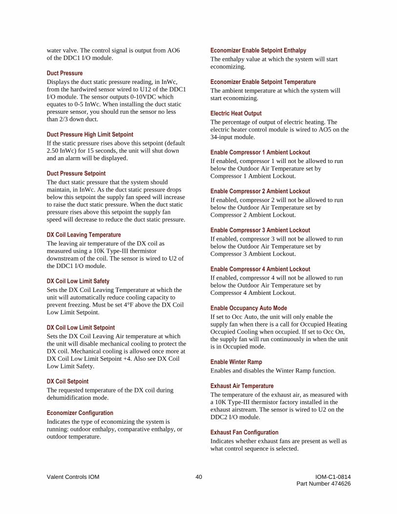
Valent Controls IOM 40 IOM-C1-0814 Part Number 474626
water valve. The control signal is output from AO6
of the DDC1 I/O module.
Duct Pressure
Displays the duct static pressure reading, in InWc,
from the hardwired sensor wired to U12 of the DDC1
I/O module. The sensor outputs 0-10VDC which
equates to 0-5 InWc. When installing the duct static
pressure sensor, you should run the sensor no less
than 2/3 down duct.
Duct Pressure High Limit Setpoint
If the static pressure rises above this setpoint (default
2.50 InWc) for 15 seconds, the unit will shut down
and an alarm will be displayed.
Duct Pressure Setpoint
The duct static pressure that the system should
maintain, in InWc. As the duct static pressure drops
below this setpoint the supply fan speed will increase
to raise the duct static pressure. When the duct static
pressure rises above this setpoint the supply fan
speed will decrease to reduce the duct static pressure.
DX Coil Leaving Temperature
The leaving air temperature of the DX coil as
measured using a 10K Type-III thermistor
downstream of the coil. The sensor is wired to U2 of
the DDC1 I/O module.
DX Coil Low Limit Safety
Sets the DX Coil Leaving Temperature at which the
unit will automatically reduce cooling capacity to
prevent freezing. Must be set 4°F above the DX Coil
Low Limit Setpoint.
DX Coil Low Limit Setpoint
Sets the DX Coil Leaving Air temperature at which
the unit will disable mechanical cooling to protect the
DX coil. Mechanical cooling is allowed once more at
DX Coil Low Limit Setpoint +4. Also see DX Coil
Low Limit Safety.
DX Coil Setpoint
The requested temperature of the DX coil during
dehumidification mode.
Economizer Configuration
Indicates the type of economizing the system is
running: outdoor enthalpy, comparative enthalpy, or
outdoor temperature.
Economizer Enable Setpoint Enthalpy
The enthalpy value at which the system will start
economizing.
Economizer Enable Setpoint Temperature
The ambient temperature at which the system will
start economizing.
Electric Heat Output
The percentage of output of electric heating. The
electric heater control module is wired to AO5 on the
34-input module.
Enable Compressor 1 Ambient Lockout
If enabled, compressor 1 will not be allowed to run
below the Outdoor Air Temperature set by
Compressor 1 Ambient Lockout.
Enable Compressor 2 Ambient Lockout
If enabled, compressor 2 will not be allowed to run
below the Outdoor Air Temperature set by
Compressor 2 Ambient Lockout.
Enable Compressor 3 Ambient Lockout
If enabled, compressor 3 will not be allowed to run
below the Outdoor Air Temperature set by
Compressor 3 Ambient Lockout.
Enable Compressor 4 Ambient Lockout
If enabled, compressor 4 will not be allowed to run
below the Outdoor Air Temperature set by
Compressor 4 Ambient Lockout.
Enable Occupancy Auto Mode
If set to Occ Auto, the unit will only enable the
supply fan when there is a call for Occupied Heating
Occupied Cooling when occupied. If set to Occ On,
the supply fan will run continuously in when the unit
is in Occupied mode.
Enable Winter Ramp
Enables and disables the Winter Ramp function.
Exhaust Air Temperature
The temperature of the exhaust air, as measured with
a 10K Type-III thermistor factory installed in the
exhaust airstream. The sensor is wired to U2 on the
DDC2 I/O module.
Exhaust Fan Configuration
Indicates whether exhaust fans are present as well as
what control sequence is selected.

Valent Controls IOM 41 IOM-C1-0814 Part Number 474626
Exhaust Fan Enable Damper Position
The percent open that the Outdoor Air Damper must
be before the exhaust fan is enabled (Default 15%).
Exhaust Fan Maximum Speed
The maximum requested speed for the exhaust fan
VFD, as a percentage of maximum possible speed.
For all exhaust fan sequences, the VFD will not be
controlled above this maximum speed.
Exhaust Fan Minimum Speed
The minimum requested speed for the exhaust fan
VFD, as a percentage of maximum possible speed.
For all exhaust fan sequences, the VFD will not be
controlled below this minimum speed.
Exhaust Fan Offset
Displays and edits the offset of the commanded
supply fan VFD speed for the exhaust fan when
Exhaust Fan Tracks Supply Fan is selected. The
exhaust fan can be slowed by setting this point
toward -20% and accelerated by setting this point
toward 20%.
Exhaust Fan Output
Indicates whether the exhaust fan command is
currently on or off. This comes from DO1 on the
DDC2 I/O module.
Exhaust Fan Reaction Speed
Determines how fast the exhaust fan will react to a
change in space pressure. Allows some PID tuning
should the exhaust fan “hunt.”
Exhaust Fan Speed
Displays the defined speed for the exhaust fan. The
rooftop unit includes a variable frequency drive
(VFD) for the exhaust fan motor. In constant volume
operation, the speed of the fan remains constant at the
defined speed (15-100%, adjustable). At 100%, the
fan speed is determined according to the setup of the
VFD (the design frequency, in Hz). The speed of the
exhaust fan may be slowed for constant volume
operation by adjusting the exhaust fan offset in the
controller (-20–20%). The minimum speed must not
be less than 15% of the design flow to ensure proper
motor operation. The demand signal comes from
AO1 on the DDC2 I/O module.
Exhaust Fan Status
Reflects the run status of the exhaust fan (U4 on the
DDC2 I/O module). When the input contacts are
closed, the exhaust fan is running. When the input
contacts are open, the exhaust fan is off.
Flat Plate Defrost Setpoint
The exhaust air temperature at which the flat plate
goes into defrost mode to prevent ice from forming in
the heat exchanger.
Gas Heat Stage 1 Output
Turns on Stage 1 of gas heat. This is wired to DO6 on
the DDC1 I/O module.
Gas Heat Stage 2 Output
Turns on Stage 2 of gas heat. This is wired to DO7 on
the DDC1 I/O module.
Gas Heat Stage 3 Output
Turns on Stage 3 of gas heat. This is wired to DO8 on
the DDC1 I/O module.
Head Pressure Control Analog Output 1
Displays the signal, as a percentage of maximum
speed, being delivered to the head pressure control
VFD that is needed to maintain the condensing
temperature in cooling mode and suction temperature
in heating mode. This is wired to AO3 on the DDC2
I/O module.
Head Pressure Control Digital Output 2
Displays the status of the head pressure control
digital output, which turns on or off one of the
condensing fans to maintain the condensing
temperature in cooling mode. This is wired to DO4
on the DDC2 I/O module.
Heat Pump Water Valve A Output
Displays the signal, as a percentage of closed
position, that is delivered to water valve A to
maintain the condensing temperature in cooling mode
and suction temperature in heating mode. This is
wired to AO3 on the DDC1 I/O module.
Heat Pump Water Valve B Output
Displays the signal, as a percentage of closed
position, that is delivered to water valve B to
maintain the condensing temperature in cooling mode
and suction temperature in heating mode. This is
wired to AO4 on the DDC1 I/O module.
Heat Wheel Defrost Setpoint
The exhaust air temperature at which the heat wheel
goes into defrost mode to prevent ice from forming
on the wheel.

Valent Controls IOM 42 IOM-C1-0814 Part Number 474626
Heat Wheel Output
Indicates whether the controller is currently
commanding the heat wheel on or off. This is wired
to DO2 on the DDC2 I/O module.
Heat Wheel Speed / Bypass Damper Position
Indicates the energy recovery demand (in percent)
that the unit is requesting. If the unit is equipped with
a heat wheel with VFD, this indicates the demand
speed (in percent) to which the heat wheel should
modulate. If the unit has a flat-plate heat exchanger,
this indicates the position of the bypass damper.
Heat Wheel Status
If a heat wheel rotation sensor is installed, this
indicates whether the heat wheel is Rotating or
Stopped. This is wired to U6 of the DDC2 I/O
module.
Heating Execution Time
Do not adjust unless given specific direction from the
factory.
Heating Integral Constant
Do not adjust unless given specific direction from the
factory.
Heating Proportional Constant
Do not adjust unless given specific direction from the
factory.
High/Low Pressure Trip Shutdown Unit if Circuits Tripped
If Yes is selected, then the unit will shut down if any
or all compressors are tripped on high/low pressure.
(When shutdown occurs depends on if point
High/Low Pressure Trip Shutdown Circuit is set for
Any Tripped or All Tripped.) If No is selected, the
unit will continue to run regardless of whether or not
compressors are tripped on high/low pressure.
High/Low Pressure Trips Shutdown Unit
If Any Tripped is selected, the unit will shut down
when any compressor on any circuit it tripped on
high/low pressure. If All Tripped is selected, then the
unit will only shut down once all compressors are
tripped on high/low pressure on all circuits.
Hot Water Case Heat Outside Temperature Enable
When the supply fan is off, the hot water valve will
be enabled at this outdoor air temperature and will
modulate to meet the Hot Water Case Heat Setpoint.
Hot Water Case Heat Setpoint
When Hot Water Case Heat Control is enabled, the
hot water valve will modulate to maintain this
temperature at the coil temperature sensor.
Hot Water Valve Position When Unit Off
Sets the position that the hot water valve will drive to
when the unit is off. If set to Modulating, the valve
will control to the Hot Water Case Heat Setpoint.
Configure the 10 Volts Opens Hot Water Valve
setpoint first.
Mixed Air Temperature
The temperature reading from the mixed air
temperature sensor. This is wired to U7 on the DDC2
I/O module.
Modulating Heat Output
The percentage of output of gas, hot water, or steam
heating. The control module or actuator is wired to
AO3 on the DDC1 I/O module.
Morning Warm Up Enable
Enables and disables the Morning Warm Up
function.
Morning Warm Up Status
Indicates whether or not the unit is currently in the
Morning Warm Up mode.
Morning Warm Up Type
Indicates whether or not Morning Warm Up exists in
the unit’s software.
Night Purge Enable
Indicates whether the system is currently in night
purge mode.
Night Purge Type
Indicates whether or not the Night Purge feature is
installed.
Occupancy Controlled By
Indicates the source of the occupancy command
currently used by the unit: unoccupied, external
input, schedule, optimal start/stop, BAS, or timed
override.
Occupancy Schedule
The occupancy state as determined from the unit
schedule.

Valent Controls IOM 43 IOM-C1-0814 Part Number 474626
Occupancy Status
The current occupancy mode of the controller.
Optimal Start Enable
This point is used to select whether the unit will
allow the optimal start functionality. Optimal start
calculates the system start time based on historical
data including space temperature, space setpoint, and
outdoor air temperature.
Optimal Start/Stop Earliest Start Time
The earliest time of day for the system to start if
needed.
Optimal Start/Stop Earliest Stop Time
The earliest time of day for the system to stop if
needed.
Optimal Stop Enable
This point is used to select whether the unit will
allow the optimal stop functionality. Optimal stop
calculates the system stop time based on historical
data including space temperature, space setpoint, and
outdoor air temperature.
Outdoor Air Damper Maximum Position
The maximum position of the damper during
occupied operation.
Outdoor Air Damper Minimum Position
The minimum position of the damper during
occupied operation.
Outdoor Air Enthalpy
Displays the value of the outdoor air enthalpy, as
calculated using the factory-installed outdoor air
relative humidity sensor and factory-installed outdoor
air temperature sensor.
Outdoor Air Relative Humidity
The level of relative humidity from the outdoor air is
measured by the field-installed RH sensor located in
the outdoor air inlet hood. The sensor provides a 0-10
VDC signal to the controller, which is wired to U5 on
the DDC1 I/O module.
Outdoor Air Temperature
The temperature of the outdoor air is measured by the
factory-installed sensor located in the outdoor air
inlet hood. The sensor is wired to U3 on the DDC1
I/O module.
Outdoor Dewpoint
The dewpoint as calculated from the outdoor
temperature and humidity values.
Outdoor Dewpoint Setpoint
If the space humidity sensor is absent or not
connected, the unit will control humidity based on the
Outdoor Air Dewpoint Setpoint. If the outdoor air
dewpoint is greater than setpoint, the unit will stage
into dehumidification.
Overcool Offset
Defines the maximum number of degrees the space
temperature can reach below setpoint before cooling
is disabled. The space temperature must be below
setpoint by this amount for 10 minutes before the
cooling is disabled.
Preheat Ambient Setpoint
If the outdoor air temperature is at or below this
temperature, the preheater will be enabled.
Preheat Output
Indicates whether the preheater is currently enabled.
This is wired to DO10 on the DDC1 I/O module.
Refrigerant Pressure Circuit A
The refrigerant pressure, in psi, of Circuit A. This is
wired to U3 on the DDC 2 I/O module.
Refrigerant Pressure Circuit B
The refrigerant pressure, in psi, of Circuit B. This is
wired to U8 on the DDC2 I/O module.
Space Dewpoint
The calculated dewpoint of the space, based on the
space temperature and humidity values that are
currently in control.
Space Dewpoint Dehumidification Disable Setpoint
If the Space Dewpoint falls below this value, then the
unit will exit dehumidification until the dewpoint in
the space is greater than this value once again. This
prevents overcooling of the space.
Space Enthalpy
Space enthalpy is calculated based on the field-
installed space temperature sensor (factory provided,
if ordered) and field-installed space humidity sensor
(factory provided, if ordered).
Space Pressure High Limit Setpoint
This is the highest allowable static pressure. If the
static pressure exceeds this limit, the fans and the unit

Valent Controls IOM 44 IOM-C1-0814 Part Number 474626
will shut down to prevent extreme over-
pressurization of the space. Default is 0.200 InWc.
Space Relative Humidity
Space RH is measured by an optional field-installed
relative humidity sensor located in the space. The
sensor provides a 0-10 VDC signal to the controller
wired to U6 on the DDC1 I/O module.
Space Relative Humidity Occupied Deadband Setpoint
Adjusts the threshold the unit uses to determine when
the space does not need dehumidification. Space
dehumidification is not requested when the space
relative humidity is less than (Occupied Space
Humidity Setpoint – Occupied Space Humidity
Deadband Setpoint).
Space Relative Humidity Setpoint
The relative humidity level that the system should
maintain in the space.
Space Relative Humidity Unoccupied Deadband Setpoint
Adjusts the threshold the unit uses to determine when
the space does not need dehumidification. Space
dehumidification is not requested when the space
relative humidity is less than (Unoccupied Space
Humidity Setpoint – Unoccupied Space Humidity
Deadband Setpoint).
Space Static Pressure
Displays the space static pressure reading, in InWc,
as reported by the field-installed space static pressure
transducer. The transducer sends a 0-10VDC signal
that equates to -0.500 to +0.500 InWc. The sensor is
wired to U1 of the DDC2 I/O module.
Space Static Pressure Setpoint
The space static pressure that the system should
maintain. As the space static pressure drops below
this setpoint, depending on the unit setup, the supply
fan speed will increase, the exhaust fan speed will
decrease, or the outdoor air damper will open to
increase the space static pressure. When the space
static pressure is above this setpoint, depending on
the unit setup, the supply fan speed will decrease, the
exhaust fan speed will increase, or the outdoor air
damper will close to reduce the space static pressure.
Space Temperature
The temperature of the space is measured by the
field-installed sensor (factory provided, if ordered)
located in the space. This is an IOU Type III
thermistor sensor wired to U4 on the DDC1 I/O
module.
Space Temperature Cooling Setpoint
When a space temperature setpoint offset is entered,
the unit will control to this setpoint when in the
cooling mode.
Space Temperature Heating Setpoint
When a space temperature setpoint offset is entered,
the unit will control to this setpoint when in the
heating mode.
Space Temperature Setpoint
The unit will operate heating and cooling to maintain
this setpoint for the space.
Space Temperature Setpoint Offset
By increasing the offset above zero (default), the unit
will operate with dual setpoints, calculated as
follows:
Space Temperature Heating Setpoint = Space Temperature Setpoint – (Space Temperature Setpoint Offset/2)
Space Temperature Cooling Setpoint = Space Temperature Setpoint + (Space Temperature Setpoint Offset/2)
The unit will control to the respective setpoint when
in the heating or cooling mode and will transition
between modes when space temperature drops below
the cooling setpoint or rises above the heating
setpoint.
Example: Space Temperature = 70°F
Space Temperature Setpoint Offset = 4°F Space Temperature Heating Setpoint = 68°F (70 – (4/2)) Space Temperature Cooling Setpoint = 72°F (70 + (4/2))
Supply Air Cooling High Deadband Setpoint
When Supply Air Deadband is enabled and the unit is
cooling, this setpoint defines the amount the Supply
Air Temperature can exceed the current control
setpoint before the control loop will respond.
Supply Air Cooling Low Deadband Setpoint
When Supply Air Deadband is enabled and the unit is
cooling, this setpoint defines the amount the Supply
Air Temperature can fall below the current control
setpoint before the control loop will respond.
Supply Air Deadband Enable Setpoint
Allows the Supply Air Temperature to go slightly
above or below the control setpoint with no
correction from the control loop. The amount of error
allowed before correction is determined by setting the
appropriate Supply Air Deadband Setpoint(s).

Valent Controls IOM 45 IOM-C1-0814 Part Number 474626
Supply Air Heating High Deadband Setpoint
When Supply Air Deadband is enabled and the unit is
heating, this defines the amount the Supply Air
Temperature can exceed the current control setpoint
before the control loop will respond.
Supply Air Heating Low Deadband Setpoint
When Supply Air Deadband is enabled and the unit is
heating, this defines the amount the Supply Air
Temperature can fall below the current control
setpoint before the control loop will respond.
Supply Air Temperature Control
This setpoint is used to force the unit into supply air
only mode. If the unit detects a space temperature
sensor it will automatically switch from Supply Air
Only control to Supply Air With Reset control. If
supply air control is desired when a space sensor is
installed, this point must be set to Force Supply Only.
In supply air temperature control, the unit attempts to
control the supply air temperature to a fixed supply
temperature setpoint. In space temperature control
with supply air temperature reset, the unit compares
the space temperature to the space temperature
heating setpoint and cooling setpoint to calculate the
supply air temperature setpoint. The unit then
modulates heating and cooling to maintain the supply
air temperature at the setpoint.
Supply Air Temperature High Limit
If the supply air temperature exceeds this temperature
limit for three minutes (adjustable via UMT, Supply
High Temp Alarm Delay) or more, the unit will go
into shutdown mode. The unit must be manually reset
to continue operation.
Supply Air Temperature High Limit Alarm Delay
If the supply air temperature reaches the Supply Air
Temperature High Limit, this is the time delay, in
minutes, before the unit goes into shutdown mode
and sends a shutdown alarm.
Supply Air Temperature Low Limit
If the supply air temperature falls below this
temperature limit for three minutes or more, the unit
will go into shutdown mode. The unit must be
manually reset to continue operation.
Supply Air Temperature Maximum Cooling Setpoint
This is the maximum supply air temperature that the
unit can reset to when configured for Supply
Temperature With Reset Control and in cooling
mode.
Supply Air Temperature Maximum Heating Setpoint
This is the maximum supply air temperature that the
unit can reset to when configured for Supply
Temperature With Reset Control and in heating
mode.
Supply Air Temperature Minimum Cooling Setpoint
This is the minimum supply air temperature that the
unit can reset to when configured for Supply
Temperature With Reset Control and in cooling
mode.
Supply Air Temperature Minimum Heating Setpoint
This is the minimum supply air temperature that the
unit can reset to when configured for Supply
Temperature With Reset Control and in heating
mode.
Supply Air Temperature Setpoint
If the system does not have a space temperature
sensor, or if one is installed and the point Force
Supply is set to True, then the unit will control the
supply air temperature to this setpoint.
Supply Fan Maximum Speed Setpoint
The maximum speed, as a percentage of design
speed, that the supply fan will be allowed to run. This
setpoint should be used when air balancing the unit.
If more air is needed, the speed can be increased to
100% of design speed. If less air is needed, the speed
can be reduced toward a minimum of 50% design
speed.
Supply Fan Minimum Speed Setpoint
The minimum speed, as a percentage of design speed,
that the supply fan VFD will be allowed to run during
any supply fan sequence.
Supply Fan Output
Indicates whether the supply fan command is
currently on or off. This is wired to DO1 on the
DDC1 I/O module.
Supply Fan Reaction Speed
Determines how fast the supply fan will react to a
change in duct pressure or space pressure (depending
on unit configuration). Allows some PID tuning
should the supply fan “hunt.”
Supply Fan Speed
Displays the speed of the supply fan as a percentage
of design speed. The rooftop unit includes a variable
frequency drive (VFD) for the supply fan motor. In
constant volume operation, the speed of the fan

Valent Controls IOM 46 IOM-C1-0814 Part Number 474626
remains constant at the defined speed (50-100%,
adjustable). At 100%, the fan speed is equal to the
design frequency, in Hz. The speed of the supply fan
may be slowed for constant volume operation by
adjusting the supply fan speed in the controller (50-
100%). The minimum speed must not be less than
50% of the design flow to ensure proper heating and
cooling operation.
For space static or variable air volume (VAV)
applications, the speed of the fan is automatically
determined by the controller (50-100%). This is
wired to AO4 on the DDC1 I/O module.
Supply Fan Status
Reflects the status of the differential pressure switch
for the supply fan (U8 on the DDC1 I/O module).
When the input contacts are closed, the supply fan is
running. When the input contacts are open, the
supply fan is off.
Supply Setpoint Calculated
If the system does not have a space temperature
sensor, or if one is installed and the point Force
Supply is set to True, then the unit will control the
supply air temperature to this setpoint.
Supply Temperature
The supply air temperature is measured by the field-
installed (factory provided) sensor located in the
supply duct immediately downstream of the rooftop
unit. The sensor is an IOU Type III thermistor that is
wired to U1on the DDC1 I/O module.
System Enable
Must be On for normal unit operation. When system
enable is Off, the unit is completely disabled and will
not operate.
Timed Override Duration
When the override button on the space sensor is
pressed, this is the amount of time that the unit will
be placed into occupied mode. When the override
expires, the unit returns to its prior state or Auto.
Unit Schedule
This is a 24-hour standalone schedule that is
programmable from either the LCD interface or the
Universal Maintenance Tool software. Occupied and
Unoccupied time can be set with minute increments.
Defaults to 24/7 Occupied operation.
Unoccupied Outdoor Air Damper Minimum
During unoccupied operation, this is the position of
the outdoor air damper on recirculation units, as a
percentage of fully open (100%).
Unoccupied Space Cooling Setpoint
This is the temperature at which cooling is enabled
during unoccupied operation.
Unoccupied Space Heating Setpoint
This is the temperature at which heating is enabled
during unoccupied operation.
Unoccupied Space Relative Humidity Setpoint
This is the Relative Humidity at which
dehumidification is enabled during unoccupied
operation.
Unoccupied Supply Fan Offset
This is the speed at which the supply fan VFD will
run when unoccupied, as a percentage of full speed
(100%). When the unit is started in night heating,
cooling, or dehumidification, the supply fan runs at
this reduced speed. If the supply fan is controlling to
maintain a duct or space static pressure, CO2, or is
configured for a remote fan input, the fan speed is not
reduced.
Water Source Heat Pump Cold Start Duration
This defines the duration of cold start mode, where
the compressors will ramp into full operation to allow
the unit to start in very cold weather.
Water Source Heat Pump Cold Start Enable Temperature
Cold start mode is enabled when the outdoor air
temperature is equal to or less than this setpoint.
Water Source Heat Pump Compressor Off Water Valve Position
For a unit with a water source heat pump, this defines
the position of the water valve when the compressors
are off.
Water Source Heat Pump Condenser Temperature Setpoint
Consult the factory to adjust this setpoint.
Water Source Heat Pump Suction Temp Low Limit
If the suction temperature is equal to or less than this
setpoint, the unit will limit or lockout the
compressors.
Valent Controls IOM 47 IOM-C1-0814 Part Number 474626
Water Source Heat Pump Water Valve Max Closed Position Setpoint
Sets the minimum water flow for the WSHP unit
coax coils. This setpoint applies to every operating
mode.
Winter Ramp Control Type
Selects whether the Winter Ramp mode, if enabled
and active, should modulated the Supply Fan or
Outdoor Air damper.
Winter Ramp Type In Control
Indicates whether the unit is currently configured to
modulate the Supply Fan or Outdoor Air damper
when in Winter Ramp mode. See Winter Ramp
Control Type.
Factory Configuration
The following information pertains to the configuration of the system. Many of these items can be viewed from the
Factory Setup menu on the LCD or UMT. For more information, please consult the factory.
Communications Type
Damper Configuration
Supply Fan Configuration
CO2 Control
Exhaust Fan Control Type
Remote Damper Control
Pre-Heater
Airflow Monitoring Type
Heating Package
Cooling Package
Energy Recovery Configuration
Unit Type
Economizer
AMD Type
Web UI
Refrigerant Monitoring
Optimal Start/Stop
Heat Pump
Morning Warmup
Night Purge
Reheat Dehumidification
Heat Wheel Rotation Sensor
Space Setpoint
I/O Map
Saved Controls Number
Sales Order Number
Tag
Software Version
Valent Controls IOM 48 IOM-C1-0814 Part Number 474626
Manual Override
The following points can be temporarily overridden
during troubleshooting. Manual overrides are
displayed on the LCD on the Manual Overrides
screen of the POINTS menu, and on the Manual
Overrides tab of the UMT and Web UI.
For more information about how to conduct a manual
override, refer to:
Manually Overriding a Setpoint From the LCD, page 5
From the UMT, page 16
From the Web UI, page 21
Override Mode
Enables and disables the manual override function.
Override mode is enabled for four hours. To cancel
the override before it expires, set Override Mode to
Disabled.
Time Remaining
Displays the time remaining before the override
mode expires.
Unit Enable
Starts or stops the operation of the system.
Supply Fan Control
Auto: The supply fan runs at the speed set by the
Supply Fan Maximum Speed Setpoint.
Manual: The supply fan runs at the speed set by the
Supply Speed override point.
Supply Fan Override
Turns the supply fan on or off.
Supply Fan Speed
Enter a speed for the supply fan. This value is used if
Supply Fan is set to Manual.
Exhaust Fan Control
Auto: The exhaust fan runs at the speed set by the
Exhaust Fan Maximum Speed setpoint.
Manual: The exhaust fan runs at the speed set by the
Exhaust Speed override point.
Exhaust Fan Override
Turns the exhaust fan on or off.
Exhaust Fan Speed
Enter a speed for the exhaust fan. This value is used
if Exhaust Fan is set to Manual.
Heat Wheel Control
Auto: The heat wheel runs at the energy recovery
capacity currently needed by the system.
Manual: The heat wheel runs at the speed set by the
Wheel Speed override point.
Wheel Override
Turns the heat wheel on or off.
Wheel Speed
Enter a speed for the heat wheel. This value is used if
Heat Wheel is set to Manual.
OA Damper Control
Auto: The outdoor air damper is controlled to the
position set by the Outdoor Air Damper Minimum
Position setpoint.
Manual: The outdoor air damper is controlled to the
position set by the OA Damper Override point.
OA Damper Override
Enter a position to control the outdoor air damper.
This value is used if OA Damper Control is set to
Manual.
Heat Cool
Auto: Controls the heating or cooling mode based on
current unit conditions.
Manual: Controls the heating or cooling components
using the values for the following compressor
override points.
Compressor 1
Turns Compressor 1 on or off.
Compressor 2
Turns Compressor 2 on or off.
Compressor 3
Turns Compressor 3 on or off.
Compressor 4
Turns Compressor 4 on or off.

Valent Controls IOM 49 IOM-C1-0814 Part Number 474626
Digital Scroll
Enter a value for the digital scroll compressor.
Modulating Heat
Enter the percentage of modulating heat to use in
override mode.
Electric Heat
Enter the percentage of electric heat to use in
override mode.
Heat 1
Turns stage 1 heating on or off.
Heat 2
Turns stage 2 heating on or off.
Heat 3
Turns stage 3 heating on or off.
Space Setpoint
Enter the space temperature that the system should
control to when in override mode.
Supply Setpoint
Enter the supply temperature that the system should
control to when in override mode.
Hot Gas Reheat
Auto: Controls to the demand called for by the main
control sequence.
Manual: Controls to the demand set by the Reheat
Override point.
Reheat Override
Enter a percentage of reheat to run in override mode.
Flat Plate
Auto: Controls the flat plate bypass damper to the
position determined by the controller.
Manual: Controls to the value set by the Flat Plate
Override point.
Flat Plate Override
Enter a position to control the flat plate bypass
damper. This value is used if Flat Plate is set to
Manual.
Pre-Heater
Turns the preheater on or off.
Coil Safety
Disables the Coil Low Limit Safety function.
Head Pressure
Auto: Controls the fan speed or water valve
position(s) to the values set by the controller.
Override: Controls the fan speed or water valve
position(s) to the values set by the following Fan
VFD/Valve A and Valve B points. This can be set to
Override only when the compressors are off.
Fan VFD/Valve A
Enter the fan speed or position of water valve A,
depending on system configuration. These can only
be overridden if the compressors are off.
Valve B
Enter the position of water valve B. This can only be
overridden if the compressors are off.
Reversing Valve
Auto: Controls the heating or cooling mode based on
current unit conditions.
Manual: Controls the heating or cooling components
using the values for the following valve override
position.
Override: Enter a reversing valve position to use in
heating or cooling mode.
Valent Controls IOM 50 IOM-C1-0814 Part Number 474626
Alarms
Alarms are displayed on the Alarms screen of the
LCD POINTS menu and on the Alarms tab of the
UMT and Web UI.
Alarms are listed here by the Web UI name. The
LCD name (IN CAPITALS) and the UMT name are
listed underneath.
Web UI Name LCD NAME, UMT Name
Alarm Status
ALARM STATUS, Alarm Status Indicates whether or not an alarm is present in the
unit.
General Alarms
General alarms are non-critical alarms that
automatically reset when conditions return to normal.
Clogged Air Filter
FILTERS, Clogged Air Filter If the filter differential pressure switch contact is
closed, which means there is little airflow through the
filter, this alarm is displayed.
CO2 Sensor
CO2 SENSOR, CO2 Sensor If a C02 sensor is installed and it shows a value of
less than 100 ppm for more than 2 minutes, this alarm
is displayed.
Exhaust Fan Fail
EXHAUST FAN, Exhaust Fan If the exhaust fan output from the controller does not
match the exhaust fan status (actual exhaust fan
output) within a 30-second time period, this alarm is
displayed.
Exhaust Temp Sensor
EXHAUST TEMP, Exhaust Temperature Sensor If an exhaust temperature sensor is installed, the unit
will monitor the value being read from the sensor and
display an alarm if the sensor is shorted (300°F) or
disconnected (-13°F) for duration of 2 minutes.
Heat Wheel Fail
HW ROTATION, Heat Wheel Rotation If there is a call for the heat wheel to rotate but the
sensor determines that it is not rotating, the unit will
display this alarm.
HPC_LPC_A
HPC_LPC_A, High Pressure/Low Pressure Cutout Circuit A
If the unit senses an open contact on either the high
pressure or low pressure switch on compressor circuit
A, this alarm is displayed. If the point Shutdown Unit
During High/Low Pressure Trip is set to Yes, the unit
will go into shutdown mode for this alarm.
HPC_LPC_B
HPC_LPC_B, High Pressure/Low Pressure Cutout Circuit B If the unit senses an open contact on either the high
pressure or low pressure switch on compressor circuit
B, this alarm is displayed. If the point Shutdown Unit
During High/Low Pressure Trip is set to Yes, the unit
will go into shutdown mode for this alarm.
Mixed Air Temp Sensor
MIXED TEMP SEN, Mixed Air Temperature Sensor If a mixed air temperature sensor is installed, the unit
will monitor the value being read from it and display
an alarm if the sensor is shorted (300°F) or
disconnected (-13°F) for a duration of 2 minutes.
OA Humidity Sensor
OA HUMIDITY SEN, Outdoor Relative Humidity Sensor If the outdoor air humidity reading is less than 5%,
this alarm is displayed.
OA Temp Sensor
OA TEMP, Outdoor Air Temperature Sensor If the outdoor air temperature sensor reading is
greater than 300°F over a 2 minute time period, this
alarm is displayed.
Refrigerant A Sensor
REF PRESSURE A, Refrigerant Pressure Transducer A If the pressure transducer reading on circuit A is less
than 25 psi or greater than 650 psi over a duration of
30 seconds, this alarm is displayed.
Refrigerant B Sensor
REF PRESSURE B, Refrigerant Pressure Transducer B If the pressure transducer reading on circuit B is less
than 25 psi or greater than 650 psi over a duration of
30 seconds, this alarm is displayed.
Space Humidity Sensor
SPACE HUMIDITY, Space Humidity Sensor If a space humidity sensor is installed, this alarm is
displayed if the value being read from the sensor is
less than 5%.
Valent Controls IOM 51 IOM-C1-0814 Part Number 474626
Space Temp Sensor
SPACE TEMP, Space Temperature Sensor If a space temperature sensor is installed, this alarm
is displayed if the value being read from it is greater
than 300°F or less than 0°F over a 2 minute time
period.
WSHP Ref Low PSI
WSHP REF LOW PSI, WSHP Low Refrigerant Pressure If the unit is a water-source heat pump, then this alarm indicates that the suction temperature of the refrigeration system is below the WSHP Suction Temp Low Limit Safety (25°F default). The digital scroll compressor will be limited in its output until the suction pressure increases again.
Shutdown Alarms
Shutdown alarms are critical alarms that shut down
the system and must be reset manually after the
condition has been corrected. Refer to the following
section on Resetting Shutdown Alarms.
Damper End Switch
DAMPER SWITCH, Outdoor Air Damper End Switch If there is a call from the controller for the unit to
open the dampers and the Damper End Switch is not
made within 1 minute, the unit will go into shutdown
mode and display this alarm.
Duct High Static
DUCT STATIC, Duct Static Pressure If the duct static pressure is greater than the user-
adjustable value (0-5 InWc; default of 2.5 InWc), the
unit will go into shutdown mode and display this
alarm.
Freezestat
FREEZESTAT, Freezestat If the Freezestat of either the hot water coil or the
chilled water coil trips (open connection on U7 of the
DDC3), the unit will go into shutdown mode, open
one or both water valves to full flow, and display this
alarm.
HPC_LPC_A Alarm
HPC_LPC_A, High Pressure/Low Pressure Cutout Circuit A
If the unit senses an open contact on either the high
pressure or low pressure switch on compressor circuit
A, this alarm is displayed. This is a shutdown alarm
if the point Shutdown Unit During High/Low
Pressure Trip is set to Yes.
HPC_LPC_B
HPC_LPC_B, High Pressure/Low Pressure Cutout Circuit B If the unit senses an open contact on either the high
pressure or low pressure switch on compressor circuit
B, this alarm is displayed. This is a shutdown alarm if
the point Shutdown Unit During High/Low Pressure
Trip is set to Yes.
Shutdown Input
SHUTDOWN INPUT, Shutdown Input If the Shutdown Input (Universal Input 16; U16) is
opened (connection to 0V broken) the unit will go
into shutdown mode and display this alarm.
Space High Static
SPACE STATIC, Space Static Pressure If the space static pressure is greater than the user
adjustable value (0-0.5 InWc; default of 0.2 InWc)
for 15 seconds, the unit will go into shutdown mode
and display this alarm.
Supply Fan Fail
SUPPLY FAN, Supply Fan If the supply fan output from the controller does not
match the supply fan status (actual supply fan output)
within a 1 minute time period, the unit will go into
shutdown mode and display this alarm.
Supply Temp High Limit
HIGH SUP TEMP, Supply Temp High If the supply temperature is greater than 120°F for 3
minutes, the unit will go into shutdown mode and
display this alarm.
Supply Temp Low Limit
LOW SUP TEMP, Supply Temp Low If the supply fan is running and the supply
temperature is less than 35°F for 5 minutes, the unit
will go into shutdown mode and display this alarm.
Supply Temp Sensor
SUPPLY TEMP SEN, Supply Temperature Sensor If a supply temperature sensor is not installed, or if
the supply temperature reads greater than 300°F or
less than 0°F over a 2 minute time period, the unit
will go into shutdown mode and display this alarm.
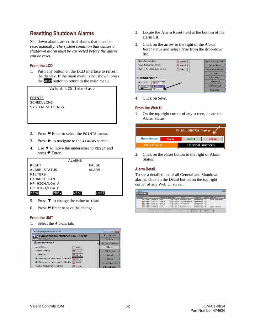
Valent Controls IOM 52 IOM-C1-0814 Part Number 474626
Resetting Shutdown Alarms
Shutdown alarms are critical alarms that must be
reset manually. The system condition that causes a
shutdown alarm must be corrected before the alarm
can be reset.
From the LCD
1. Push any button on the LCD interface to refresh
the display. If the main menu is not shown, press
the MENU button to return to the main menu.
Valent LCD Interface POINTS SCHEDULING SYSTEM SETTINGS
2. Press Enter to select the POINTS menu.
3. Press ► to navigate to the ALARMS screen.
4. Use ▼ to move the underscore to RESET and
press Enter.
ALARMS RESET FALSE ALARM STATUS ALARM FILTERS EXHAUST FAN HP HIGH/LOW A HP HIGH/LOW B MENU PREV NEXT LAST
5. Press ▼ to change the value to TRUE.
6. Press Enter to save the change.
From the UMT
1. Select the Alarms tab.
2. Locate the Alarm Reset field at the bottom of the
alarm list.
3. Click on the arrow to the right of the Alarm
Reset status and select True from the drop-down
list.
4. Click on Save.
From the Web UI
1. On the top right corner of any screen, locate the
Alarm Status.
2. Click on the Reset button to the right of Alarm
Status.
Alarm Detail
To see a detailed list of all General and Shutdown
alarms, click on the Detail button on the top right
corner of any Web UI screen.

Valent Controls IOM 53 IOM-C1-0814 Part Number 474626
Troubleshooting
Refreshing the LCD Screen
If the LCD screen has frozen, gone blank, or is not
responding, refresh the screen by reloading the
driver.
1. Locate the Universal Input 3 (U3) on the DDC1
module.
2. Locate 0V directly to the right of U3.
3. Place a jumper wire from U3 to 0V for more
than one second.
4. The LCD should refresh and display the initial
Valent screen.
If the Valent screen does not appear, check the LCD
cord connection to both the controller and the LCD
screen to ensure a good connection. Repeat the above
steps. If the Valent screen still does not appear,
contact Valent Service.
Clearing a Station Error
If the UMT cannot connect to the controller, the
following error message is displayed:
If this message is displayed immediately after
clicking on the Connect button, the user name or
password may be incorrect. These fields are case
sensitive. Rekey the user name and password
carefully and attempt to reconnect.
If this message is displayed after the connection
status has progressed beyond 10%, the LAN adapter
settings may be incorrect. Check the adapter settings
for the correct configuration, then attempt to
reconnect. If adapter settings are changed, restart the
UMT before trying to reconnect.
If the LAN adapter settings are correct but the UMT
still cannot communicate with the controller, reboot
the controller as described in the next section, then
attempt to reconnect. For further help, contact Valent
Service.
Rebooting the Controller
If the controller is not communicating with the UMT,
first check the LAN adapter settings. If the settings
are correct but the controller is still not responding,
the controller must be rebooted.
1. Disconnect power from the controller.
2. Wait four minutes for the controller to
completely de-energize. All lights must be off.
3. Reconnect the power.
After rebooting the controller, if the UMT still cannot
communicate, contact Valent Service.
Locating the Station Folder
To successfully update the software or copy a station,
the station folder must be in the correct location. The
compressed folder must be copied to the following
location and then unzipped:
C:\Lynxspring\Universal Maintenance Tool\stations\
Follow the instructions below for locating the station
folder using Windows XP or Windows 7.
Using Windows XP
1. Click on the start menu.
2. Click on My Computer.
3. Double click on the Local Disk C: icon. If the
UMT software is installed on another drive, click
on the icon for that drive.
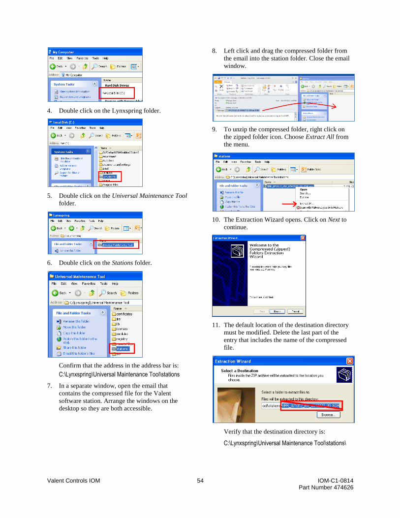
Valent Controls IOM 54 IOM-C1-0814 Part Number 474626
4. Double click on the Lynxspring folder.
5. Double click on the Universal Maintenance Tool
folder.
6. Double click on the Stations folder.
Confirm that the address in the address bar is:
C:\Lynxspring\Universal Maintenance Tool\stations
7. In a separate window, open the email that
contains the compressed file for the Valent
software station. Arrange the windows on the
desktop so they are both accessible.
8. Left click and drag the compressed folder from
the email into the station folder. Close the email
window.
9. To unzip the compressed folder, right click on
the zipped folder icon. Choose Extract All from
the menu.
10. The Extraction Wizard opens. Click on Next to
continue.
11. The default location of the destination directory
must be modified. Delete the last part of the
entry that includes the name of the compressed
file.
Verify that the destination directory is:
C:\Lynxspring\Universal Maintenance Tool\stations\

Valent Controls IOM 55 IOM-C1-0814 Part Number 474626
12. Click on Next.
13. When the Extraction Wizard is done, click on
Finish.
14. The compressed folder and the Valent software
station folder will both be listed in the
destination directory. The Valent station folder
contains the unzipped software objects.
Using Windows 7
1. Click on the Windows Start orb.
2. Click on Computer.
3. Double click on the (C:)Local Disk icon. If the
UMT software is installed on another drive, click
on the icon for that drive.
4. Double click on the Lynxspring folder.
5. Double click on the Universal Maintenance Tool
folder.
6. Double click on the Stations folder.
Confirm that the address in the address bar is:
(C:)Local DiskLynxspringUniversal Maintenance Toolstations
7. In a separate window, open the email that
contains the compressed file for the Valent
software station. Arrange the windows on the
desktop so they are both accessible.
8. In the email, click on the attachment for the
compressed folder.

Valent Controls IOM 56 IOM-C1-0814 Part Number 474626
9. Select Save File and click OK. (On some
systems, simply select Save.)
10. Specify where to save the file. In the Save As
box, sequentially select Computer/ C:/
Lynxspring/ Universal Maintenance Tool/
Stations. Mozilla Firefox users can simply click
on the file name and drag the icon to the
destination location.
11. When the download is complete, close the
window.
12. The compressed Valent software station folder
should then be located in the destination
directory. Verify the path in the address bar is
correct.
13. To unzip the compressed folder, right click on
the zipped folder icon. Choose Extract All from
the menu.
14. The Extraction Wizard opens. The default
location of the destination directory must be
modified. Delete the last part of the entry that
includes the name of the compressed file.
Verify that the destination directory is:
C:\Lynxspring\Universal Maintenance Tool\stations\
15. Click on Extract.
16. The compressed folder and the Valent software
station folder will both be listed in the
destination directory. The Valent station folder
contains the unzipped software objects, as shown
below.

Valent Controls IOM 57 IOM-C1-0814 Part Number 474626
Copying a Station
The UMT Station Copier utility can be used to copy
application programs (stations) between the PC and
the connected unit controller.
1. On the UMT, select the Platform tab.
2. Double click on the arrows to the right of Station
Copier.
3. On the Station Copier screen, the information on
the left side of the screen represents folders and
files from the connected PC. The information on
the right side of the screen represents the station
running on the connected unit/controller.
Station files received from Valent should be placed in
the following folder. Stations copied from the
controller to the local PC can also be found in this
same folder.
C:\Lynxspring\Universal Maintenance Tool\stations
Folders received from Valent must be placed into the
correct directory for the controller to recognize the
files and operate properly. Refer to the prior section
Locating the Station Folder on page 53 for more
information.
Uploading from the Controller to the PC
The station copier can also be used to upload or
backup the station from the controller to the PC.
1. Select the controller's station from the right side
of the screen.
2. Select Copy to upload/backup the station from
the controller to the PC.
3. Use the suggested station name. Select Next.
4. Select Copy every file, then select Next.
5. Select Finish.
6. A pop-up indicates that the existing station is
being saved. This screen automatically closes.
WARNING: Clicking on the Abort button cancels the station
transfer and could damage the internal software. Do
not press Abort unless instructed by the factory.

Valent Controls IOM 58 IOM-C1-0814 Part Number 474626
7. When the file transfer is complete, select Close.
Downloading from the PC to the Controller
1. Click on the desired station from the list on the
left side of the screen.
2. Select Copy to start the station transfer wizard
and download the station from the PC to the
controller.
3. Use the suggested station name. Click on Next.
4. If a station is already present in the controller,
the wizard warns that the existing station will be
replaced by the new one, which is correct. Click
on Next.
5. Select Copy every file, then select Next.
6. Select Auto-Start, then select Next.
7. Select Reboot the remote host, then select Next.
8. Select Finish.
9. A pop-up indicates that the existing station is
being shut down. This screen automatically
closes when the shutdown is complete.
WARNING: Clicking on the Abort button cancels the station
transfer and could damage the internal software. Do
not press Abort unless instructed by the factory.
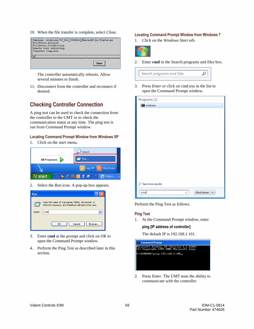
Valent Controls IOM 59 IOM-C1-0814 Part Number 474626
10. When the file transfer is complete, select Close.
The controller automatically reboots. Allow
several minutes to finish.
11. Disconnect from the controller and reconnect if
desired.
Checking Controller Connection
A ping test can be used to check the connection from
the controller to the UMT or to check the
communication status at any time. The ping test is
run from Command Prompt window.
Locating Command Prompt Window from Windows XP
1. Click on the start menu.
2. Select the Run icon. A pop-up box appears.
3. Enter cmd at the prompt and click on OK to
open the Command Prompt window.
4. Perform the Ping Test as described later in this
section.
Locating Command Prompt Window from Windows 7
1. Click on the Windows Start orb.
2. Enter cmd in the Search programs and files box.
3. Press Enter or click on cmd.exe in the list to
open the Command Prompt window.
Perform the Ping Test as follows.
Ping Test
1. At the Command Prompt window, enter
ping [IP address of controller]
The default IP is 192.168.1.101.
2. Press Enter. The UMT tests the ability to
communicate with the controller.
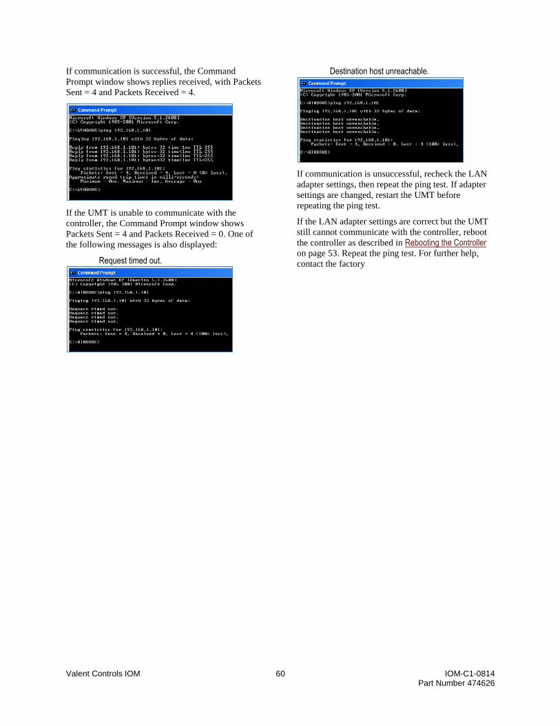
Valent Controls IOM 60 IOM-C1-0814 Part Number 474626
If communication is successful, the Command
Prompt window shows replies received, with Packets
Sent = 4 and Packets Received = 4.
If the UMT is unable to communicate with the
controller, the Command Prompt window shows
Packets Sent = 4 and Packets Received = 0. One of
the following messages is also displayed:
Request timed out.
Destination host unreachable.
If communication is unsuccessful, recheck the LAN
adapter settings, then repeat the ping test. If adapter
settings are changed, restart the UMT before
repeating the ping test.
If the LAN adapter settings are correct but the UMT
still cannot communicate with the controller, reboot
the controller as described in Rebooting the Controller on page 53. Repeat the ping test. For further help,
contact the factory
Valent Controls IOM 61 IOM-C1-0814 Part Number 474626
Sequence of Operation
1. OCCUPANCY
1.1. The controller shall enable occupancy under any one of the following conditions.
A. Internal time clock determines occupancy is true.
B. Dry contact is closed (internal time clock must be disabled).
C. BAS communication signal determines occupancy is true.
D. Timed override signal through space temperature sensor is true.
E. Optimal start sequence enabled.
1.2. The controller shall perform the following functions in the occupied mode.
A. Modulate the outdoor air damper and return air damper to the minimum position (return air damper
modulates inversely to the outdoor air damper).
B. Enable the supply fan upon closure of the outdoor air damper end switch.
C. Enable the exhaust fan 30 seconds after closure of the supply fan pressure switch.
1.3. The controller shall disable occupancy under any one of the following conditions.
A. Internal time clock determines occupancy is false.
B. Dry contact is opened (internal time clock must be disabled).
C. BAS communication signal determines occupancy is false.
D. Timed override signal through space temperature sensor is false.
1.4. The controller shall perform the following functions after occupancy is disabled.
A. Cooling, dehumidification, heating, or economizer shall be disabled.
B. After 30 seconds (adj.) the supply fan shall be disabled.
C. Outdoor air damper shall be de-energized and fail closed.
D. Return air damper shall be de-energized and fail open.
2. NIGHT SETBACK
2.1. Unit shall enable night setback under any one of the following conditions.
A. Relative humidity in the space is greater than 55% (adj.) OR dew point in the space is greater than
53°F (adj.).
B. Space temperature is greater than 80°F (adj.).
C. Space temperature is less than 60°F (adj.).
2.2. The controller shall perform the following functions in the night setback.
A. Supply fan shall enable.
B. Temperature control sequence shall enable.
2.3. The controller shall disable night setback under any one of the following conditions.
A. Space conditions are satisfied.
B. Internal time clock in microprocessor controller determines unoccupied mode.
C. Dry contact for occupied mode is closed.
3. TEMPERATURE CONTROL
3.1. The controller shall enable the temperature control sequence when any of the following conditions are
met.
A. Occupancy is true.
B. Night setback mode enabled.
3.2. The supply air temperature set point shall be determined by the following inputs.
A. [Supply air control] User-defined supply air temperature set point.
B. [Space temperature and humidity control with supply air reset] PID loop driven by user-defined
space temperature set point within the supply minimum and maximum set points.
3.3. The controller shall enable the following modes of operation in order to maintain the supply air
temperature set point.
A. Heating (if equipped).
B. Energy recovery (if equipped).
C. Economizer (if equipped).
D. Cooling.

Valent Controls IOM 62 IOM-C1-0814 Part Number 474626
3.4. Heating
A. The controller shall enable heating under the following condition.
a. Temperature control PID loop determines heating required due to the difference between the
supply air temperature and supply air temperature set point.
B. The controller shall perform the following functions in heating mode.
a. [Wheel, fixed speed] Enable the energy recovery wheel at full speed.
b. [Wheel, modulating] Enable the energy recovery wheel at full speed.
c. [Sensible plate] Close heat exchanger bypass damper.
d. Modulate capacity to the supply air temperature set point.
C. When energy recovery is present
a. [Wheel, fixed speed] Enable the energy recovery wheel at full speed.
b. [Wheel, modulating] When the leaving exhaust air temperature reaches 36°F, the controller
modulates the energy recovery wheel to achieve an exhaust air temperature of 46°F. After the
exhaust air temperature has reached 46°F, the energy wheel continues to operate at full speed.
c. [Sensible plate] Modulate the bypass dampers to maintain the supply air temperature set point.
3.5. Cooling
A. The controller shall enable cooling under the following conditions.
a. Temperature control PID loop determines cooling required due to the difference between the
supply air temperature and supply air temperature set point.
B. The controller shall perform the following functions in cooling mode.
a. [Wheel, fixed speed] Enable the energy recovery wheel at full speed.
b. [Wheel, modulating] Modulate the energy recovery wheel to maintain the supply air set point.
c. [Sensible plate] Modulate the bypass dampers to maintain the supply air temperature set point.
d. Modulate capacity to the supply air temperature set point.
3.6. Economizer
A. The controller shall enter the economizer mode under the following conditions.
a. Temperature control PID loop determines cooling required due to the difference between the
supply air temperature and supply air temperature set point.
b. [Reference enthalpy] The outdoor air enthalpy is less than the outdoor air enthalpy reference set
point.
c. [Comparative enthalpy] The outdoor air enthalpy is less than the space air enthalpy.
d. [Reference temperature] The outdoor air temperature is less than the outdoor air temperature
reference set point.
B. The controller shall perform the following functions in economizer mode.
a. [Wheel, fixed speed] Disable energy recovery wheel rotation.
b. [Wheel, modulating] Disable energy recovery wheel rotation.
c. [Sensible plate] Open heat exchanger bypass damper.
d. Modulate the outdoor air damper and return air damper positions to maintain the supply air
temperature set point.
4. DEHUMIDIFICATION
4.1. The controller shall enable the dehumidification control sequence when both of the following conditions
are met.
A. [Supply air control] Outdoor dew point is greater than the outdoor air dew point set point AND the
outdoor air temperature is greater than the supply air temperature set point.
B. [Space temperature and humidity control with supply air reset] Outdoor dew point is greater than the
outdoor air dew point set point AND the outdoor air temperature is greater than the supply air
temperature set point OR the space relative humidity is greater than the space relative humidity set
point AND the space dew point is above 55°F.
4.2. The controller shall perform the following functions in the dehumidification mode.
A. [Wheel, fixed speed] If the ambient temperature is greater than the space temperature, enable the
energy recovery wheel at full speed.
B. [Wheel, modulating] If the ambient temperature is greater than the space temperature, enable the
energy recovery wheel at full speed.
C. [Sensible plate] If the ambient temperature is greater than the space temperature, close
D. Modulate capacity to the supply air temperature set point.

Valent Controls IOM 63 IOM-C1-0814 Part Number 474626
E. Modulate cooling capacity to maintain the coil leaving air temperature set point.
F. Modulate hot gas reheat valve to maintain the supply air temperature set point.
5. COOLING & REFRIGERATION – AIR COOLED PACKAGED DIRECT EXPANSION
5.1. In cooling mode the controller shall perform the following functions.
A. Enable the Digital Scroll™ compressor and modulate capacity to maintain supply air temperature set
point.
B. If the Digital Scroll™ compressor is not able to maintain the supply air temperature, additional fixed
stages of capacity shall be enabled and the Digital Scroll™ shall continue to modulate to maintain
the supply air temperature set point.
C. If the combination of multiple compressors provides lowers the supply air temperature below its set
point, the controller shall disable one or more fixed stages of capacity.
5.2. In dehumidification mode the controller shall perform the following functions.
A. Enable a fixed stage of capacity to maintain or exceed the evaporator coil leaving air temperature set
point.
B. Modulate the hot gas reheat valve to maintain the supply air temperature set point.
C. Enable an additional fixed stage of capacity to maintain or exceed the evaporator coil leaving air
temperature set point (310, 350, and 450 casings only).
D. Enable the Digital Scroll™ compressor to maintain the evaporator coil leaving air temperature set
point.
E. Enable the final fixed stage of capacity and modulate the Digital Scroll™ to maintain the evaporator
coil leaving air temperature set point (310, 350, and 450 casings only).
5.3. [Standard Condensing Performance] To maintain a consistent condensing temperature in cooling and
dehumidification mode, the controller shall perform functions.
A. Enable a single bank of condensing fans to maintain optimum condensing temperatures.
B. As head pressure rises, a mechanical switch shall enable additional condensing fans as needed to
maintain optimum condensing temperatures.
C. As head pressure lowers, individual condensing fans will disable condensing fans maintain optimum
condensing temperatures.
5.4. [Active Head Pressure Control 1.0] To maintain a consistent condensing temperature in cooling and
dehumidification mode, the controller shall perform functions.
A. Enable and modulate single bank of condensing fans with a variable frequency drive to maintain a
condensing temperature of 110°F.
B. As head pressure rises, a mechanical switch shall enable additional condensing fans and first bank of
condensing fans will modulate to maintain a condensing temperature of 110°F.
C. As head pressure lowers, individual condensing fans will disable condensing fans first bank of
condensing fans will modulate to maintain a condensing temperature of 110°F.
5.5. [Active Head Pressure Control 2.0] To maintain a consistent condensing temperature in cooling and
dehumidification mode, the controller shall perform functions.
A. Enable and modulate all condensing fans with EC motors at the same speed to maintain a condensing
temperature of 110°F.
6. COOLING & REFRIGERATION – AIR SOURCE HEAT PUMP
6.1. In cooling mode the controller shall perform the following functions.
A. Enable the Digital Scroll™ compressor and modulate capacity to maintain supply air temperature set
point.
B. If the Digital Scroll™ compressor is not able to maintain the supply air temperature, additional fixed
stages of capacity shall be enabled and the Digital Scroll™ shall continue to modulate to maintain
the supply air temperature set point.
C. If the combination of multiple compressors provides lowers the supply air temperature below its set
point, the controller shall disable one or more fixed stages of capacity.
6.2. In dehumidification mode the controller shall perform the following functions.
A. Enable a fixed stage of capacity to maintain or exceed the evaporator coil leaving air temperature set
point.
B. Modulate the hot gas reheat valve to maintain the supply air temperature set point.

Valent Controls IOM 64 IOM-C1-0814 Part Number 474626
C. Enable an additional fixed stage of capacity to maintain or exceed the evaporator coil leaving air
temperature set point (310, 350, and 450 casings only).
D. Enable the Digital Scroll™ compressor to maintain the evaporator coil leaving air temperature set
point.
E. Enable the final fixed stage of capacity and modulate the Digital Scroll™ to maintain the evaporator
coil leaving air temperature set point (310, 350, and 450 casings only).
6.3. [Active Head Pressure Control 1.0] To maintain a consistent condensing temperature in cooling and
dehumidification mode, the controller shall perform functions.
A. Enable and modulate single bank of condensing fans with a variable frequency drive to maintain a
condensing temperature of 110°F.
B. As head pressure rises, a mechanical switch shall enable additional condensing fans and first bank of
condensing fans will modulate to maintain a condensing temperature of 110°F.
C. As head pressure lowers, individual condensing fans will disable condensing fans first bank of
condensing fans will modulate to maintain a condensing temperature of 110°F.
6.4. [Active Head Pressure Control 2.0] To maintain a consistent condensing temperature in cooling and
dehumidification mode, the controller shall perform functions.
A. Enable and modulate all condensing fans with EC motors at the same speed to maintain a condensing
temperature of 110°F.
7. COOLING & REFRIGERATION – WATER SOURCE HEAT PUMP
7.1. In cooling mode the controller shall perform the following functions.
A. Enable the Digital Scroll™ compressor and modulate capacity to maintain supply air temperature set
point.
B. If the Digital Scroll™ compressor is not able to maintain the supply air temperature, additional fixed
stages of capacity shall be enabled and the Digital Scroll™ shall continue to modulate to maintain
the supply air temperature set point.
C. If the combination of multiple compressors provides lowers the supply air temperature below its set
point, the controller shall disable one or more fixed stages of capacity.
7.2. In dehumidification mode the controller shall perform the following functions.
A. Enable a fixed stage of capacity to maintain or exceed the evaporator coil leaving air temperature set
point.
B. Modulate the hot gas reheat valve to maintain the supply air temperature set point.
C. Enable the Digital Scroll™ compressor to maintain the evaporator coil leaving air temperature set
point.
7.3. To maintain a consistent condensing temperature in cooling and dehumidification mode the controller
shall modulate the water valve on each circuit to maintain a condensing temperature of 110°F.
8. HEATING – INDIRECT GAS FURNACE
8.1. In heating mode the unit controller shall perform the following actions.
A. Enable indirect gas furnace.
B. Modulate capacity to maintain the supply air temperature set point.
8.2. When an enable signal is received from the unit controller, the furnace controller shall initiate the
following ignition sequence.
A. Enable the combustion blower at full speed for 15 seconds on 110/210/310 casings and 30 seconds
on 350/450 casings.
B. Modulate the gas valve to 100% on 110/210/310 casings and 55% on 350/450 casing furnace.
C. Enable the spark igniter for 10 seconds on 110/210/310 casings and 5 seconds on 350/450 casings.
D. Hold the ignition modulation set point for 30 seconds on 110/210/310 casings and 120 seconds for
350/450 casings.
8.3. Once the ignition sequence is complete, the furnace controller shall perform the following actions.
A. Modulate the gas valve based on the modulation signal from the unit controller.
B. Lower and raise the speed of the combustion fan based on the modulation signal from the unit
controller (two-speed).

Valent Controls IOM 65 IOM-C1-0814 Part Number 474626
8.4. If the furnace controller does not receive confirmation of a successful ignition sequence (flame providing
switch not made), it shall initiate the ignition sequence two additional times on 110/210/310 casings and
three additional times on 350/450 casings.
8.5. Upon the loss of the enable signal from the unit controller, the furnace controller shall perform the
following actions.
A. Modulate the gas valve to 0%.
B. Increase the combustion blower to full speed for 30 seconds on 110/210/310 casings and 60 seconds
for 350/450 casings.
9. HEATING – ELECTRIC HEAT
9.1. The electric heater shall modulate capacity in order to maintain the supply air temperature set point.
10. HEATING – TEMPERATOR
10.1. The electric heater shall modulate capacity in order to maintain the supply air temperature set point.
10.2. If the SCR electric heater is unable to maintain the supply air temperature set point, the unit controller
shall disable the SCR electric heater and enable the indirect gas furnace.
10.3. In heating mode the unit controller shall perform the following actions.
A. Enable indirect gas furnace.
B. Modulate capacity to maintain the supply air temperature set point.
10.4. When an enable signal is received from the unit controller, the furnace controller shall initiate the
following ignition sequence.
A. Enable the combustion blower at full speed for 15 seconds on 110/210/310 casings and 30 seconds
on 350/450 casings.
B. Modulate the gas valve to 100% on 110/210/310 casings and 55% on 350/450 casing furnace.
C. Enable the spark igniter for 10 seconds on 110/210/310 casings and 5 seconds on 350/450 casings.
D. Hold the ignition modulation set point for 30 seconds on 110/210/310 casings and 120 seconds for
350/450 casings.
10.5. Once the ignition sequence is complete, the furnace controller shall perform the following actions.
A. Modulate the gas valve based on the modulation signal from the unit controller.
B. Lower and raise the speed of the combustion fan based on the modulation signal from the unit
controller (two-speed).
10.6. If the furnace controller does not receive confirmation of a successful ignition sequence (flame providing
switch not made), it shall initiate the ignition sequence two additional times on 110/210/310 casings and
three additional times on 350/450 casings.
10.7. Upon the loss of the enable signal from the unit controller, the furnace controller shall perform the
following actions.
A. Modulate the gas valve to 0%.
10.8. Increase the combustion blower to full speed for 30 seconds on 110/210/310 casings and 60 seconds for
350/450 casings.
11. HEATING – WATER SOURCE HEAT PUMP
11.1. In heating mode the controller shall perform the following functions.
A. Enable the Digital Scroll™ compressor and modulate capacity to maintain supply air temperature set
point.
B. If the Digital Scroll™ compressor is not able to maintain the supply air temperature, additional fixed
stages of capacity shall be enabled and the Digital Scroll™ shall continue to modulate to maintain
the supply air temperature set point.
C. If the combination of multiple compressors provides too much cooling capacity, the controller will
disable fixed stages of capacity and continue to modulate the Digital Scroll™ compressor to maintain
the supply air temperature set point.
11.2. To maintain a consistent condensing temperature in heating mode the controller shall modulate the water
valve on each circuit to maintain a condensing temperature of 110°F.
12. HEATING – AIR SOURCE HEAT PUMP
12.1. In heating mode the controller shall perform the following functions.

Valent Controls IOM 66 IOM-C1-0814 Part Number 474626
A. Enable the Digital Scroll™ compressor and modulate capacity to maintain supply air temperature set
point.
B. If the Digital Scroll™ compressor is not able to maintain the supply air temperature, additional fixed
stages of capacity shall be enabled and the Digital Scroll™ shall continue to modulate to maintain
the supply air temperature set point.
C. If the combination of multiple compressors provides too much cooling capacity, the controller will
disable fixed stages of capacity and continue to modulate the Digital Scroll™ compressor to maintain
the supply air temperature set point.
D. Enable condensing fans at full speed.
12.2. [No Defrost Mode] If the unit is not capable of meeting the supply air temperature set point the controller
will disable all refrigeration and enable the mechanical heating source.
12.3. [DefrostPLUS] The controller shall initiate a defrost sequence to remove the accumulation of frost build
up on the outdoor coil.
A. The controller shall enter the defrost mode when all of the following conditions are met.
a. Suction temperature is less than 30°F.
b. Suction temperature is equal to or greater than the outdoor air dew point less 25°F.
B. The controller shall perform the following functions in the defrost mode.
a. Outdoor air damper shall close.
b. Return air damper shall open (operates inversely of outdoor air damper).
c. Exhaust fan (if equipped) shall disable.
d. Condensing fans shall disable.
e. Energy recovery wheel (if equipped) shall disable.
f. Supply fan shall modulate to the maximum design speed.
g. Reversing valve shall enable to make indoor coil the evaporator and outdoor coil the condenser.
h. Compressor(s) shall enable and/or modulate to full capacity.
i. Mechanical heat source enabled to maintain supply air temperature set point.
C. The controller shall exit the defrost mode under the following conditions.
a. Condensing temperature reaches 60°F.
D. If the controller enables three defrost modes in one hour of operation, the controller will disable the
heat pump and enable the mechanical form of heating.
13. MODULATION SEQUENCES
13.1. Supply Fan Modulation
A. The controller shall modulate the supply fan speed based on the following input.
a. Duct static pressure.
b. Space static pressure.
c. 0-10 VDC input (signal provided by others).
d. BAS communication.
13.2. Damper Modulation
A. The controller shall modulate the outdoor air and return air damper based on the following input.
a. Space static pressure.
b. Outdoor air volume.
c. Space carbon dioxide.
d. BAS communication.
13.3. Exhaust Fan Modulation
A. The controller shall modulate the exhaust fan speed based on the following input.
a. Space static pressure.
b. 0-10 VDC input (signal provided by others).
c. BAS communication.
d. Supply fan tracking.

Valent Controls IOM 67 IOM-C1-0814 Part Number 474626
Warranty
UNISON COMFORT TECHNOLOGIES
LIMITED WARRANTY & DISCLAIMER POLICY (Please read the Unison Comfort Technologies terms and conditions
of sale Section 9 for additional details, conditions and exclusions.)
PRODUCT WARRANTY
Unison warrants that at the time of delivery and for a period of twelve (12) months from the initial startup or
eighteen (18) months from the date of shipment, whichever is less, its products will be free from defects in materials
and manufacture, provided that the products have been installed properly, maintained and operated under normal
conditions and serviced in accordance with Unison’s instructions, and are operating within capacities and ratings set
forth in design specifications. Labor or consumable parts are not included in this limited standard product
warranty. Consumable parts include, but are not limited to, refrigerant, belts and filters.
START-UP LABOR LIMITED WARRANTY
While labor is not included in the Unison standard product warranty, Unison offers a limited labor warranty, for a
period beginning on the start-up date and continuing for sixty (60) days, with the completion and documentation of a
qualified start-up. The limited labor warranty will not be available if the product warranty has expired.
Start-up services are included on all Innovent compressorized products, and may be available as an option on other
Unison products. These services must be performed by a Unison Certified Technician. Startup services include
verifying proper operation of the unit, including proper refrigerant charge and repair of minor refrigerant leaks
outside the coil. At the completion of start-up, an approved start-up record must be submitted to the Unison service
department for processing. Once the start-up record is received, the (60) day limited labor warranty, from date of
start-up, will be activated. Labor associated with the diagnosis, validation and repair of warranty parts failures will
be covered outside of the start-up, at a negotiated labor rate.
CONSIDERATIONS REGARDING PARTS-SUPPLIED-BY-OTHERS
Unison may supply equipment at a customer’s request which has components, like controls, sensors, drives, which
are engineered, provided, programmed or configured by other non-Unison parties. Unison does not provide a
warranty for these parts or components. These components can be mounted in the factory or at the jobsite. In these
instances, Unison’s support is limited to verification of basic functionality of the components and not the overall
operation or integration of the equipment within the overall building HVAC system. As stated in the Unison Terms
& Conditions – No warranty herein extended shall apply to repair or correction of conditions arising from improper
or incorrectly connected air duct, piping, wiring, power supply, blown fuses, freezing, improper Product control
when programmed by non-Seller controls, or personnel, or by anyone other than Seller employee or its
representative. In these situations, Unison will assist in the diagnosis of issues and provide support to the customer
provided the customer issues a purchase order to cover Unison’s expenses in doing so.

Valent Controls IOM 68 IOM-C1-0814 Part Number 474626
Extended Limited Warranty Certificate
This certificate verifies that has purchased a Limited Extended Warranty policy from
Unison Comfort Technologies for the following unit(s):
Unit Brand: Choose Trademark
Unit Model or Tag#:
Unit Serial #:
The Extended Limited Warranty coverage for this unit is as follows:
All Unison warranties begin at start-up or 6 months after the date of shipment from the Unison
factory, whichever occurs first. The ship date for the units noted above is . Please refer to
the Unison Comfort Technologies terms and conditions of sales for additional details, conditions
and exclusions.
Unit/Component Options Coverage
Purchased
Length of Warranty
Extension
(1,3,5, 10 or 15 years)
Parts Only
Or
Parts & Labor
DX Unit
Chilled Water Unit
Heat Pump Unit
Unit Casing Only
Components
Coil(s)
Energy Recovery Wheel(s)
Fan motor(s)
Furnace Heat Exchanger(s)
Air-to-air Heat Exchanger(s)
DDC Controller(s)
VFD(s)
Compressor(s)

Valent Controls IOM 69 IOM-C1-0814 Part Number 474626
Index
Alarms Alarm Reset setpoint .................................................... 38 Definitions ..................................................................... 50 Resetting shutdown alarms .......................................... 52
BACnet ............................................................................. 23 From LCD ....................................................................... 7 Setpoint list ................................................................... 31
CO2 setpoints .................................................................. 38
Control devices ................................................................. 3
Copying a station ............................................................ 57 Locating the station folder ............................................ 53
Dehumidification Setpoints....................................................................... 39
Downloading a station .................................................... 58
Duct static pressure setpoints ...................................... 40
Economizer Setpoints....................................................................... 40
Exhaust setpoints ........................................................... 40
Factory setup .................................................................. 47
Fan speed Changing from LCD ........................................................ 5 Changing from UMT ..................................................... 16 Changing from Web UI ................................................. 21
General alarms ................................................................ 50
Head pressure setpoints ................................................ 41
Input/output points Configuration ................................................................ 24
IP address From the LCD ................................................................. 7 From the UMT .............................................................. 14 From the Web UI .................................................... 10, 20
LCD controller Description...................................................................... 3 Map................................................................................. 9 Screen reset ................................................................. 53 Using the LCD ................................................................ 3
LonTalk ............................................................................ 23 From LCD ....................................................................... 8 Setpoint list ................................................................... 34
Manual override Descriptions .................................................................. 48 From the LCD ................................................................. 5 From the UMT .............................................................. 16 From the Web UI .......................................................... 21
Optimal start/stop setpoints .......................................... 43
Outdoor air setpoints ..................................................... 43
Relative humidity setpoints ........................................... 44
Schedule Changing from LCD ....................................................... 6 Changing from UMT ..................................................... 17 Changing from Web UI ................................................ 22
Sequence of control ....................................................... 61
Setpoint Changing from LCD ....................................................... 5 Changing from UMT ..................................................... 15 Changing from Web UI ................................................ 20 Overriding from LCD ...................................................... 5 Overriding from UMT ................................................... 16 Overriding from Web UI ............................................... 21
Setpoint list ..................................................................... 27 BACnet list ................................................................... 31 Descriptions ................................................................. 37 LCD map ........................................................................ 9 LonTalk list ................................................................... 34 Table ............................................................................ 27 UMT map ..................................................................... 18
Shutdown alarms ........................................................... 51 Resetting ...................................................................... 52
Space temperature setpoints ........................................ 44
Static pressure setpoints .............................................. 44 Duct static pressure setpoints ...................................... 40
Status summary on UMT ............................................... 15
Supply temperature setpoints ....................................... 46
TCP/IP Configuring from the LCD .............................................. 7 Configuring from the UMT ............................................ 14
Temperature setpoints ................................................... 44
Time and date Changing from UMT ..................................................... 14
Troubleshooting ............................................................. 53
Universal Maintenance Tool (UMT) Description ..................................................................... 3 Map .............................................................................. 18 Troubleshooting connection ......................................... 59 Using the UMT ............................................................. 10
Uploading a Station ........................................................ 57
Warranty .......................................................................... 67
Web User Interface (Web UI) Description ..................................................................... 3 Using the Web UI ......................................................... 20

©August 2014 Valent® Air Management Systems
Valent® is a business of Unison™ Comfort Technologies
For service inquiries, please contact: Unison™ Comfort Technologies Technical Service (800)789-8550 [email protected]