controller link operation manual - omron systems/plcs... · controller link units operation manual...
TRANSCRIPT

Cat. No. W309-E1-11SYSMACCS1W-CLK23
Controller Link Units
CS1W-CLK21-V1CJ1W-CLK23CJ1W-CLK21-V1C200HW-CLK21CVM1-CLK21CQM1H-CLK21(CS1W-RPT01/02/03 Repeater Units)
OPERATION MANUAL

CS1W-CLK23CS1W-CLK21-V1CJ1W-CLK23CJ1W-CLK21-V1C200HW-CLK21CVM1-CLK21CQM1H-CLK21(CS1W-RPT01/02/03 Repeater Units)
Controller Link UnitsOperation ManualRevised May 2008

iv

Notice:OMRON products are manufactured for use according to proper procedures by a qualified operatorand only for the purposes described in this manual.
The following conventions are used to indicate and classify precautions in this manual. Always heedthe information provided with them. Failure to heed precautions can result in injury to people or dam-age to property.
!DANGER Indicates an imminently hazardous situation which, if not avoided, will result in death orserious injury. Additionally, there may be severe property damage.
!WARNING Indicates a potentially hazardous situation which, if not avoided, could result in death orserious injury. Additionally, there may be severe property damage.
!Caution Indicates a potentially hazardous situation which, if not avoided, may result in minor ormoderate injury, or property damage.
OMRON Product ReferencesAll OMRON products are capitalized in this manual. The word “Unit” is also capitalized when it refers toan OMRON product, regardless of whether or not it appears in the proper name of the product.
The abbreviation “Ch,” which appears in some displays and on some OMRON products, often means“word” and is abbreviated “Wd” in documentation in this sense.
The abbreviation “PLC” means Programmable Controller. “PC” is used, however, in some Program-ming Device displays to mean Programmable Controller.
Visual AidsThe following headings appear in the left column of the manual to help you locate different types ofinformation.
Note Indicates information of particular interest for efficient and convenient opera-tion of the product.
1,2,3... 1. Indicates lists of one sort or another, such as procedures, checklists, etc.
OMRON, 1997All rights reserved. No part of this publication may be reproduced, stored in a retrieval system, or transmitted, in any form, orby any means, mechanical, electronic, photocopying, recording, or otherwise, without the prior written permission ofOMRON.
No patent liability is assumed with respect to the use of the information contained herein. Moreover, because OMRON is con-stantly striving to improve its high-quality products, the information contained in this manual is subject to change withoutnotice. Every precaution has been taken in the preparation of this manual. Nevertheless, OMRON assumes no responsibilityfor errors or omissions. Neither is any liability assumed for damages resulting from the use of the information contained inthis publication.
v

Unit Versions of CS/CJ-series Controller Link Units
Unit VersionsA “unit version” has been introduced to manage CS/CJ-series Controller Link Units according to differ-ences in functionality accompanying upgrades.
Unit Version Notation on ProductsThe unit version code is provided on the nameplate of the CS/CJ-series Controller Link Units for whichunit versions are being managed. This system applies to Controller Link Units with unit version 1.2 orlater.
Confirming Unit Versions with Support SoftwareCX-Programmer version 5.0 or higher can be used to confirm the unit version in the Unit ManufacturingInformation.
1,2,3... 1. 1. In the I/O Table Window, right-click on the Controller Link Unit, and thenselect Unit Manufacturing Information.
2. The following Unit Manufacturing Information Dialog Box will be displayed.
Example: In this Unit Manufacturing Information Dialog Box, unit version1.2 is displayed. Use this dialog box to confirm the unit version of the Con-troller Link Unit that is connected online.
CS1W-CLK21-V1
CONTROLLER LINK UNIT
Lot No. 040901 0000 Ver.1.2
OMRON Corporation MADE IN JAPAN
Example: CS1W-CLK21-V1 CS-series Controller Link Unit
Nameplate
Unit version 1.2
Indicates the unit version.
vi

Using the Unit Version LabelsUnit version labels are provided with the product. These labels can be attached to the front of previousController Link Units to differentiate between Controller Link Units of different unit versions.
Unit Version NotationThe unit versions are indicated in this manual as follows:
Function Support by Unit Version
Note (1) Use the CX-Net in CX-Programmer version 5.0 or later to set a data linkarea in which the number of send and receive words exceeds 12,000words, or to set data link tables that allocate the same area for Area 1 andArea 2.
(2) Use the CX-Integrator Data Link Setting Tool version 3.2.1.1 or later to setdata link tables with more than 1,000 send words per node. For informa-tion on checking the version number, refer to Checking the CX-IntegratorData Link Setting Tool Version on page viii.
Unit Versions and Manufacturing Dates/Lot Numbers
Notation in product nameplate Notation in this manual Remarks
Ver.1.2 or later after the lot number CS/CJ-series Controller Link Units with unit version 1.2 or later
Information for which no particular version is specified applies to all unit versions.Blank after the lot number Pre-Ver. 1.2 CS/CJ-series Controller
Link Units
Functions Unit version 2.0 Unit version 1.2 Earlier version (Pre-Ver. 1.2)
CS1W-CLK23CJ1W-CLK23
CS1W-CLK21-V1CJ1W-CLK21-V1
CS1W-CLK21-V1CJ1W-CLK21-V1
Maximum number of data link words (data link area for sending/receiving that is created for a sin-gle node in a single CPU Unit)
20,000 max. (See note 1.) 12,000 max.
Number of send words per node (total of area 1 and area 2)
4,000 words max. (See note 2.)
1,000 words max.
Data Link Area The same area can be allocated for both Area 1 and Area 2.
The same area cannot be allocated for both Area 1 and Area 2.
Maximum number of Units con-nected to a single CPU Unit
8 Units 4 Units
Model Until August 2004 From September 2004 From September 2007
CS1W-CLK21-V1 Pre-Ver. 1.2 Unit version 1.2 (Lot No. 040901 and later)CJ1W-CLK21-V1
CS1W-CLK23 --- --- Unit version 2.0
CJ1W-CLK23
vii

Checking the CX-Integrator Data Link Setting Tool Version1. Start the CX-Integrator and select Tool - Start Data Link.
2. In the Select Network Dialog Box, select 1 Controller Link and click the OKButton.
3. The Data Link Table Setting Tool (Data Link Component) will start. SelectHelp - About Datalink Component....
viii

4. The Version Dialog Box will be displayed. Check the Data Link Componentversion number.
If CX-One version 2.0 or later Support Software is being used with an olderversion of the Data Link Component, use the CX-One automatic updatefunction to upgrade to the latest version.
ix

x

TABLE OF CONTENTS
PRECAUTIONS . . . . . . . . . . . . . . . . . . . . . . . . . . . . . . . . . . . xxi1 Intended Audience . . . . . . . . . . . . . . . . . . . . . . . . . . . . . . . . . . . . . . . . . . . . . . . . . . . . . . . . xxii
2 General Precautions . . . . . . . . . . . . . . . . . . . . . . . . . . . . . . . . . . . . . . . . . . . . . . . . . . . . . . . xxii
3 Safety Precautions. . . . . . . . . . . . . . . . . . . . . . . . . . . . . . . . . . . . . . . . . . . . . . . . . . . . . . . . . xxii
4 Operating Environment Precautions . . . . . . . . . . . . . . . . . . . . . . . . . . . . . . . . . . . . . . . . . . . xxiii
5 Applications Precautions. . . . . . . . . . . . . . . . . . . . . . . . . . . . . . . . . . . . . . . . . . . . . . . . . . . . xxiv
6 Conformance to EC Directives . . . . . . . . . . . . . . . . . . . . . . . . . . . . . . . . . . . . . . . . . . . . . . . xxvi
SECTION 1Features and System Configuration . . . . . . . . . . . . . . . . . . . 1
1-1 Overview . . . . . . . . . . . . . . . . . . . . . . . . . . . . . . . . . . . . . . . . . . . . . . . . . . . . . . . . . . . . . . . . 2
1-2 Specifications and Configurations . . . . . . . . . . . . . . . . . . . . . . . . . . . . . . . . . . . . . . . . . . . . 12
1-3 Selection of Communications Functions . . . . . . . . . . . . . . . . . . . . . . . . . . . . . . . . . . . . . . . 27
1-4 Basic Procedures . . . . . . . . . . . . . . . . . . . . . . . . . . . . . . . . . . . . . . . . . . . . . . . . . . . . . . . . . . 27
1-5 Application Precautions . . . . . . . . . . . . . . . . . . . . . . . . . . . . . . . . . . . . . . . . . . . . . . . . . . . . 29
SECTION 2Basic Procedures. . . . . . . . . . . . . . . . . . . . . . . . . . . . . . . . . . . 33
2-1 Data Links Procedures . . . . . . . . . . . . . . . . . . . . . . . . . . . . . . . . . . . . . . . . . . . . . . . . . . . . . 34
2-2 Message Service Procedure . . . . . . . . . . . . . . . . . . . . . . . . . . . . . . . . . . . . . . . . . . . . . . . . . 42
SECTION 3Installation and Wiring . . . . . . . . . . . . . . . . . . . . . . . . . . . . . 45
3-1 Component Names and Functions . . . . . . . . . . . . . . . . . . . . . . . . . . . . . . . . . . . . . . . . . . . . 46
3-2 Unit Installation. . . . . . . . . . . . . . . . . . . . . . . . . . . . . . . . . . . . . . . . . . . . . . . . . . . . . . . . . . . 60
3-3 Wiring . . . . . . . . . . . . . . . . . . . . . . . . . . . . . . . . . . . . . . . . . . . . . . . . . . . . . . . . . . . . . . . . . . 68
3-4 Constructing Networks with Repeater Units. . . . . . . . . . . . . . . . . . . . . . . . . . . . . . . . . . . . . 80
SECTION 4Preparations for Communications . . . . . . . . . . . . . . . . . . . . 87
4-1 CS-series Controller Link Units . . . . . . . . . . . . . . . . . . . . . . . . . . . . . . . . . . . . . . . . . . . . . . 88
4-2 CJ-series Controller Link Units . . . . . . . . . . . . . . . . . . . . . . . . . . . . . . . . . . . . . . . . . . . . . . 91
4-3 C200HX/HG/HE Controller Link Units . . . . . . . . . . . . . . . . . . . . . . . . . . . . . . . . . . . . . . . . 95
4-4 CVM1 and CV-series Controller Link Units. . . . . . . . . . . . . . . . . . . . . . . . . . . . . . . . . . . . . 99
4-5 CQM1H-series Controller Link Units. . . . . . . . . . . . . . . . . . . . . . . . . . . . . . . . . . . . . . . . . . 102
4-6 Repeater Units. . . . . . . . . . . . . . . . . . . . . . . . . . . . . . . . . . . . . . . . . . . . . . . . . . . . . . . . . . . . 104
SECTION 5Data Links . . . . . . . . . . . . . . . . . . . . . . . . . . . . . . . . . . . . . . . . 107
5-1 What Are Data Links?. . . . . . . . . . . . . . . . . . . . . . . . . . . . . . . . . . . . . . . . . . . . . . . . . . . . . . 108
5-2 Setting Data Links. . . . . . . . . . . . . . . . . . . . . . . . . . . . . . . . . . . . . . . . . . . . . . . . . . . . . . . . . 115
5-3 Starting and Stopping Data Links . . . . . . . . . . . . . . . . . . . . . . . . . . . . . . . . . . . . . . . . . . . . . 155
5-4 Checking Data Link Status . . . . . . . . . . . . . . . . . . . . . . . . . . . . . . . . . . . . . . . . . . . . . . . . . . 158
xi

TABLE OF CONTENTS
SECTION 6Message Service. . . . . . . . . . . . . . . . . . . . . . . . . . . . . . . . . . . . 1676-1 Introduction . . . . . . . . . . . . . . . . . . . . . . . . . . . . . . . . . . . . . . . . . . . . . . . . . . . . . . . . . . . . . . 168
6-2 Selecting Communications Instructions . . . . . . . . . . . . . . . . . . . . . . . . . . . . . . . . . . . . . . . . 189
6-3 Using the Message Service . . . . . . . . . . . . . . . . . . . . . . . . . . . . . . . . . . . . . . . . . . . . . . . . . . 192
6-4 FINS Commands and Responses. . . . . . . . . . . . . . . . . . . . . . . . . . . . . . . . . . . . . . . . . . . . . . 202
6-5 Commands and Responses for Controller Link Units . . . . . . . . . . . . . . . . . . . . . . . . . . . . . . 204
6-6 Commands and Responses for C200HX/HG/HE and CQM1H-series PLCs . . . . . . . . . . . . 215
6-7 Response Codes . . . . . . . . . . . . . . . . . . . . . . . . . . . . . . . . . . . . . . . . . . . . . . . . . . . . . . . . . . . 228
SECTION 7Network Interconnections . . . . . . . . . . . . . . . . . . . . . . . . . . . 237
7-1 What is Network Interconnection? . . . . . . . . . . . . . . . . . . . . . . . . . . . . . . . . . . . . . . . . . . . . 238
7-2 Remote Programming and Monitoring . . . . . . . . . . . . . . . . . . . . . . . . . . . . . . . . . . . . . . . . . 240
7-3 Routing Tables . . . . . . . . . . . . . . . . . . . . . . . . . . . . . . . . . . . . . . . . . . . . . . . . . . . . . . . . . . . . 243
7-4 Setting Routing Tables. . . . . . . . . . . . . . . . . . . . . . . . . . . . . . . . . . . . . . . . . . . . . . . . . . . . . . 244
SECTION 8Communications Timing . . . . . . . . . . . . . . . . . . . . . . . . . . . . 251
8-1 Communications Mechanism . . . . . . . . . . . . . . . . . . . . . . . . . . . . . . . . . . . . . . . . . . . . . . . . 252
8-2 Communications Cycle Time . . . . . . . . . . . . . . . . . . . . . . . . . . . . . . . . . . . . . . . . . . . . . . . . 255
8-3 Data Link I/O Response Time . . . . . . . . . . . . . . . . . . . . . . . . . . . . . . . . . . . . . . . . . . . . . . . . 257
8-4 Message Delay Times . . . . . . . . . . . . . . . . . . . . . . . . . . . . . . . . . . . . . . . . . . . . . . . . . . . . . . 264
SECTION 9Troubleshooting and Maintenance . . . . . . . . . . . . . . . . . . . . 273
9-1 Troubleshooting Using Indicators . . . . . . . . . . . . . . . . . . . . . . . . . . . . . . . . . . . . . . . . . . . . . 274
9-2 Status Area and Troubleshooting. . . . . . . . . . . . . . . . . . . . . . . . . . . . . . . . . . . . . . . . . . . . . . 290
9-3 Error Log . . . . . . . . . . . . . . . . . . . . . . . . . . . . . . . . . . . . . . . . . . . . . . . . . . . . . . . . . . . . . . . . 310
9-4 Troubleshooting Error Messages in CX-Net Data Link Table Check . . . . . . . . . . . . . . . . . . 318
9-5 Cleaning and Inspection . . . . . . . . . . . . . . . . . . . . . . . . . . . . . . . . . . . . . . . . . . . . . . . . . . . . 320
9-6 Handling Precautions. . . . . . . . . . . . . . . . . . . . . . . . . . . . . . . . . . . . . . . . . . . . . . . . . . . . . . . 321
SECTION 10Adding Nodes and Editing Active Data Link Tables. . . . . . 329
10-1 Adding Nodes Using a Repeater Unit . . . . . . . . . . . . . . . . . . . . . . . . . . . . . . . . . . . . . . . . . . 330
10-2 Changing the Data Link Tables with Active Data Links . . . . . . . . . . . . . . . . . . . . . . . . . . . 334
AppendicesA Standard Models . . . . . . . . . . . . . . . . . . . . . . . . . . . . . . . . . . . . . . . . . . . . . . . . . . . . . . . . . . 341
B Memory Areas . . . . . . . . . . . . . . . . . . . . . . . . . . . . . . . . . . . . . . . . . . . . . . . . . . . . . . . . . . . 345
C Using the Relay Terminal Block . . . . . . . . . . . . . . . . . . . . . . . . . . . . . . . . . . . . . . . . . . . . . . 363
xii

TABLE OF CONTENTS
Index . . . . . . . . . . . . . . . . . . . . . . . . . . . . . . . . . . . . . . . . . . . . 367Revision History . . . . . . . . . . . . . . . . . . . . . . . . . . . . . . . . . . . 373
xiii

xiv

About this Manual:This manual describes the installation, setup, and operation of the CS1W-CLK23, CS1W-CLK21-V1,CJ1W-CLK23, CJ1W-CLK21-V1, C200HW-CLK21,CVM1-CLK21, and CQM1H-CLK21 Controller LinkUnits for C200HX/HG/HE, CS/CJ-series, CVM1, CQM1H-series, and CV-series PLCs, and includesthe sections described below. The Controller Link Units are used to connect these PLCs to a Control-ler Link Network. Information is also provided in this manual on CS1W-RPT01/02/03 Repeater Units.The following three manuals are directly related to application of the Controller Link Network.
Depending on the system, you may also need the CX-Programmer, or a Programming Console. Referto the body of this manual for details. Please read this manual and related manuals carefully and besure you understand the information provided before attempting to install and operate a Controller LinkUnit.
Precautions provides general precautions for using the Controller Link Unit and related devices. Section 1 provides basic information on Controller Link Networks, and will give the reader an overviewof what Controller Link Networks can do and how best to use them.Section 2 describes the basic procedures to use the Controller Link Unit. The settings necessary forusing each of the functions are also explained briefly. For more details, refer to the following sectionson individual functions.
Name Contents Cat. No. (suffixes omitted)
CS1W-CLK23, CS1W-CLK21-V1, CJ1W-CLK23, CJ1W-CLK21-V1, C200HW-CLK21,CVM1-CLK21, CQM1H-CLK21 Controller Link Units (Wired and Opti-cal) Operation Manual (this manual)
Installation, setup, and operating procedures for the Optical and Wired Controller Link Units. Controller Link Units are used to connect C200HX/HG/HE, CV-series, and CS1-series PCs to a Controller Link Net-work.
W309
3G8F7-CLK13-E, 3G8F7-CLK12-EV1, 3G8F7-CLK53-E, 3G8F7-CLK52-EV1, 3G8F7-CLK23-E, 3G8F7-CLK21-EV1 Controller Link Support Boards for PCI Bus Operation Manual
Operating procedures for Controller Link Support Boards for PCI bus connections. Controller Link Support Boards are used to connect IBM PC/ATs or compatibles to a Controller Link Network.
W383
3G8F7-CLK13-E, 3G8F7-CLK12-EV1, 3G8F7-CLK53-E, 3G8F7-CLK52-EV1, 3G8F7-CLK23-E, 3G8F7-CLK21-EV1 Controller Link Support Boards for PCI Bus Installation Guide
Installation and setup procedures for Controller Link Support Boards for PCI bus connections. Controller Link Support Boards are used to connect IBM PC/ATs or compatibles to a Controller Link Network.
W467
3G8F5-CLK11-E, 3G8F5-CLK21-E Controller Link Support Boards for ISA Bus Operation Manual
Installation, setup, and operating procedures for Controller Link Support Boards for ISA bus connec-tions. Controller Link Support Boards are used to connect IBM PC/ATs or compatibles to a Controller Link Network.
W307
CS1W-CLK13, CS1W-CLK12-V1, CVM1-CLK12, CS1W-CLK53, CS1W-CLK52-V1, CVM1-CLK52 Optical Ring Controller Link Units Operation Manual
Installation, setup, and operating procedures for the Optical Ring Controller Link Units. Controller Link Units are used to connect C200HX/HG/HE CV-series, and CS1-series PCs to a Controller Link Net-work.
W370
C200HW-ZW3AT2-E-V2 Controller Link Support Software Operation Manual
Installation and operating procedures for the Con-troller Link Support Software. The Controller Link Support Software enables manually set data links and other procedures for a Controller Link Network.
W369
xv

Section 3 describes how to install a Controller Link Unit and how to wire the Controller Link Network.Details are also provided on installation, wiring, and basic operating procedures of Repeater Units,including information on using them to construct networks.Section 4 describes the settings required for starting communications. These basic settings arerequired for both data links function and the message service. Carry out the settings described herebefore turning on power to the Controller Link Unit.Section 5 describes how to use data links in a Controller Link Network. Refer to SECTION 2 BasicProcedures for an outline of data link application.Section 6 explains how to use the message service provided by a Controller Link Unit. It also explainsthe FINS commands and responses supported by Controller Link Units and those supported byC200HX/HG/HE, CS/CJ-series, CVM1 and CV-series PLCs.Section 7 describes the method used to connect multiple networks through CS/CJ-series, CVM1, andCV-series PLCs. The section also describes remote programming and monitoring with ProgrammingDevices.Section 8 explains details on Controller Link Network communications. Refer to this section for net-work communications that require accurate communications timing.Section 9 provides information on troubleshooting errors that occur during Controller Link Unit opera-tion, as well as daily inspection, cleaning, and other maintenance procedures.Section 10 provides information on functions that can be performed without turning OFF the PLCpower to the existing network, such as adding nodes to the Controller Link Network using a RepeaterUnit and changing data link tables while the data links are active. Appendix A provides a list of standard OMRON products related to Controller Link Networks.Appendix B provides easy reference to the words in PLC memory areas used by Controller Link Net-works.Appendix C provides information on how to use the CJ1W-TB101 Wired Controller Link Unit RelayTerminal Block, including details on connection and replacement.
!WARNING Failure to read and understand the information provided in this manual mayresult in personal injury or death, damage to the product, or product failure.Please read each section in its entirety and be sure you understand the infor-mation provided in the section and related sections before attempting any ofthe procedures or operations given.
xvi

Read and Understand this ManualPlease read and understand this manual before using the product. Please consult your OMRON representative if you have any questions or comments.
Warranty and Limitations of Liability
WARRANTY
OMRON's exclusive warranty is that the products are free from defects in materials and workmanship for a period of one year (or other period if specified) from date of sale by OMRON.
OMRON MAKES NO WARRANTY OR REPRESENTATION, EXPRESS OR IMPLIED, REGARDING NON-INFRINGEMENT, MERCHANTABILITY, OR FITNESS FOR PARTICULAR PURPOSE OF THE PRODUCTS. ANY BUYER OR USER ACKNOWLEDGES THAT THE BUYER OR USER ALONE HAS DETERMINED THAT THE PRODUCTS WILL SUITABLY MEET THE REQUIREMENTS OF THEIR INTENDED USE. OMRON DISCLAIMS ALL OTHER WARRANTIES, EXPRESS OR IMPLIED.
LIMITATIONS OF LIABILITY
OMRON SHALL NOT BE RESPONSIBLE FOR SPECIAL, INDIRECT, OR CONSEQUENTIAL DAMAGES, LOSS OF PROFITS OR COMMERCIAL LOSS IN ANY WAY CONNECTED WITH THE PRODUCTS, WHETHER SUCH CLAIM IS BASED ON CONTRACT, WARRANTY, NEGLIGENCE, OR STRICT LIABILITY.
In no event shall the responsibility of OMRON for any act exceed the individual price of the product on which liability is asserted.
IN NO EVENT SHALL OMRON BE RESPONSIBLE FOR WARRANTY, REPAIR, OR OTHER CLAIMS REGARDING THE PRODUCTS UNLESS OMRON'S ANALYSIS CONFIRMS THAT THE PRODUCTS WERE PROPERLY HANDLED, STORED, INSTALLED, AND MAINTAINED AND NOT SUBJECT TO CONTAMINATION, ABUSE, MISUSE, OR INAPPROPRIATE MODIFICATION OR REPAIR.
xvii

Application Considerations
SUITABILITY FOR USE
OMRON shall not be responsible for conformity with any standards, codes, or regulations that apply to the combination of products in the customer's application or use of the products.
At the customer's request, OMRON will provide applicable third party certification documents identifying ratings and limitations of use that apply to the products. This information by itself is not sufficient for a complete determination of the suitability of the products in combination with the end product, machine, system, or other application or use.
The following are some examples of applications for which particular attention must be given. This is not intended to be an exhaustive list of all possible uses of the products, nor is it intended to imply that the uses listed may be suitable for the products:
• Outdoor use, uses involving potential chemical contamination or electrical interference, or conditions or uses not described in this manual.
• Nuclear energy control systems, combustion systems, railroad systems, aviation systems, medical equipment, amusement machines, vehicles, safety equipment, and installations subject to separate industry or government regulations.
• Systems, machines, and equipment that could present a risk to life or property.
Please know and observe all prohibitions of use applicable to the products.
NEVER USE THE PRODUCTS FOR AN APPLICATION INVOLVING SERIOUS RISK TO LIFE OR PROPERTY WITHOUT ENSURING THAT THE SYSTEM AS A WHOLE HAS BEEN DESIGNED TO ADDRESS THE RISKS, AND THAT THE OMRON PRODUCTS ARE PROPERLY RATED AND INSTALLED FOR THE INTENDED USE WITHIN THE OVERALL EQUIPMENT OR SYSTEM.
PROGRAMMABLE PRODUCTS
OMRON shall not be responsible for the user's programming of a programmable product, or any consequence thereof.
xviii

Disclaimers
CHANGE IN SPECIFICATIONS
Product specifications and accessories may be changed at any time based on improvements and other reasons.
It is our practice to change model numbers when published ratings or features are changed, or when significant construction changes are made. However, some specifications of the products may be changed without any notice. When in doubt, special model numbers may be assigned to fix or establish key specifications for your application on your request. Please consult with your OMRON representative at any time to confirm actual specifications of purchased products.
DIMENSIONS AND WEIGHTS
Dimensions and weights are nominal and are not to be used for manufacturing purposes, even when tolerances are shown.
PERFORMANCE DATA
Performance data given in this manual is provided as a guide for the user in determining suitability and does not constitute a warranty. It may represent the result of OMRON's test conditions, and the users must correlate it to actual application requirements. Actual performance is subject to the OMRON Warranty and Limitations of Liability.
ERRORS AND OMISSIONS
The information in this manual has been carefully checked and is believed to be accurate; however, no responsibility is assumed for clerical, typographical, or proofreading errors, or omissions.
xix

xx

xxi
PRECAUTIONS
This section provides general precautions for using the Controller Link Unit and related devices.
The information contained in this section is important for the safe and reliable application of the Controller LinkUnit. You must read this section and understand the information contained before attempting to set up or operatea Controller Link Unit.
1 Intended Audience . . . . . . . . . . . . . . . . . . . . . . . . . . . . . . . . . . . . . . . . . . . . . xxii2 General Precautions . . . . . . . . . . . . . . . . . . . . . . . . . . . . . . . . . . . . . . . . . . . . xxii3 Safety Precautions. . . . . . . . . . . . . . . . . . . . . . . . . . . . . . . . . . . . . . . . . . . . . . xxii4 Operating Environment Precautions . . . . . . . . . . . . . . . . . . . . . . . . . . . . . . . . xxiii5 Applications Precautions. . . . . . . . . . . . . . . . . . . . . . . . . . . . . . . . . . . . . . . . . xxiv6 Conformance to EC Directives . . . . . . . . . . . . . . . . . . . . . . . . . . . . . . . . . . . . xxvi

Intended Audience 1
1 Intended AudienceThis manual is intended for the following personnel, who must also haveknowledge of electrical systems (an electrical engineer or the equivalent).
• Personnel in charge of installing FA systems.
• Personnel in charge of designing FA systems.
• Personnel in charge of managing FA systems and facilities.
2 General PrecautionsThe user must operate the product according to the performance specifica-tions described in the operation manuals.
Before using the product under conditions which are not described in themanual or applying the product to nuclear control systems, railroad systems,aviation systems, vehicles, combustion systems, medical equipment, amuse-ment machines, safety equipment, and other systems, machines, and equip-ment that may have a serious influence on lives and property if usedimproperly, consult your OMRON representative.
Make sure that the ratings and performance characteristics of the product aresufficient for the systems, machines, and equipment, and be sure to providethe systems, machines, and equipment with double safety mechanisms.
This manual provides information for programming and operating OMRONPLCs and related devices. Be sure to read this manual before attempting touse the software and keep this manual close at hand for reference duringoperation.
!WARNING It is extremely important that a PLC and all PLC Units be used for the speci-fied purpose and under the specified conditions, especially in applications thatcan directly or indirectly affect human life. You must consult with your OMRONrepresentative before applying a PLC System to the above mentioned appli-cations.
3 Safety Precautions
!WARNING Do not attempt to take any Unit apart while the power is being supplied. Doingso may result in electric shock.
!WARNING Do not touch any of the terminals or terminal blocks while the power is beingsupplied. Doing so may result in electric shock.
!WARNING Provide safety measures in external circuits (i.e., not in the ProgrammableController), including the following items, to ensure safety in the system if anabnormality occurs due to malfunction of the PLC or another external factoraffecting the PLC operation. Not doing so may result in serious accidents.
• Fail-safe measures must be taken by the customer to ensure safety in theevent of incorrect, missing, or abnormal signals caused by broken signallines, momentary power interruptions, or other causes.
• Emergency stop circuits, interlock circuits, limit circuits, and similar safetymeasures must be provided in external control circuits.
xxii

Operating Environment Precautions 4
• The PLC will turn OFF all outputs when its self-diagnosis function detectsany error or when a severe failure alarm (FALS) instruction is executed.As a countermeasure for such errors, external safety measures must beprovided to ensure safety in the system.
• The PLC outputs may remain ON or OFF due to deposition or burning ofthe output relays or destruction of the output transistors. As a counter-measure for such problems, external safety measures must be providedto ensure safety in the system.
• When the 24-VDC output (service power supply to the PLC) is overloadedor short-circuited, the voltage may drop and result in the outputs beingturned OFF. As a countermeasure for such problems, external safetymeasures must be provided to ensure safety in the system.
!Caution Execute online edit only after confirming that no adverse effects will becaused by extending the cycle time. Otherwise, the input signals may not bereadable.
!Caution Confirm safety at the destination node before transferring a program toanother node or changing contents of the I/O memory area. Doing either ofthese without confirming safety may result in injury.
4 Operating Environment Precautions
!Caution Do not operate the control system in the following locations:
• Locations subject to direct sunlight.
• Locations subject to temperatures or humidity outside the range specifiedin the specifications.
• Locations subject to condensation as the result of severe changes in tem-perature.
• Locations subject to corrosive or flammable gases.
• Locations subject to dust (especially iron dust) or salts.
• Locations subject to exposure to water, oil, or chemicals.
• Locations subject to shock or vibration.
!Caution Take appropriate and sufficient countermeasures when installing systems inthe following locations:
• Locations subject to static electricity or other forms of noise.
• Locations subject to strong electromagnetic fields.
• Locations subject to possible exposure to radioactivity.
• Locations close to power supplies.
!Caution The operating environment of the PLC System can have a large effect on thelongevity and reliability of the system. Improper operating environments canlead to malfunction, failure, and other unforeseeable problems with the PLCSystem. Be sure that the operating environment is within the specified condi-tions at installation and remains within the specified conditions during the lifeof the system.
xxiii

Applications Precautions 5
5 Applications PrecautionsObserve the following precautions when using the Controller Link Unit.
!WARNING Failure to abide by the following precautions could lead to serious or possiblyfatal injury. Always heed these precautions.
• Always ground the system to 100 Ω or less when installing the system toprotect against electrical shock.
• Always turn OFF the power supply or the backup power supply to the PLCor the computer before attempting any of the following. Performing any ofthe following with the power supply turned ON may lead to electricalshock:
• Installing or removing the Controller Link Unit.
• Assembling the Units.
• Setting DIP or rotary switches.
• Connecting or disconnecting any cables or wiring.
• Connecting or disconnecting any terminal block.
!Caution Failure to abide by the following precautions could lead to faulty operation orthe PLC or the system or could damage the PLC or PLC Units. Always heedthese precautions.
• Always use the power supply voltages specified in the operation manuals.An incorrect voltage may result in malfunction or burning.
• Take appropriate measures to ensure that the specified power with therated voltage and frequency is supplied. Be particularly careful in placeswhere the power supply is unstable. An incorrect power supply may resultin malfunction.
• Install external breakers and take other safety measures against short-cir-cuiting in external wiring. Insufficient safety measures against short-cir-cuiting may result in burning.
• Separate the line ground terminal (LG) from the functional ground termi-nal (GR) on the Power Supply Unit before performing withstand voltagetests or insulation resistance tests. Not doing so may result in burning.
• Do not attempt to disassemble, repair, or modify any Units. Any attempt todo so may result in malfunction, fire, or electric shock.
• Install the Units properly as specified in the operation manuals. Improperinstallation of the Units may result in malfunction.
• Be sure that all the mounting screws, terminal screws, and cable connec-tor screws are tightened to the torque specified in the relevant manuals.Incorrect tightening torque may result in malfunction.
• Leave the label attached to the Unit when wiring. Removing the label mayresult in malfunction if foreign matter enters the Unit.
• Remove the label after the completion of wiring to ensure proper heat dis-sipation. Leaving the label attached may result in malfunction.
• Use crimp terminals for wiring. Do not connect bare stranded wiresdirectly to terminals. Connection of bare stranded wires may result inburning.
xxiv

Applications Precautions 5
• Double-check all wiring and switch settings before turning ON the powersupply. Incorrect wiring may result in burning.
• Wire all connections correctly.
• Mount Units only after checking terminal blocks completely.
• Be sure that the Bus Connection Units and other items with lockingdevices are properly locked into place. Improper locking may result inmalfunction.
• Use special packing box when transporting the Controller Link Unit. Han-dle the product carefully so that no excessive vibration or impact isapplied to the product during transportation.
• Check the user program for proper execution before actually running it onthe Unit. Not checking the program may result in an unexpected opera-tion.
• Confirm that no adverse effect will occur in the system before attemptingany of the following. Not doing so may result in an unexpected operation.
• Changing the operating mode of the PLC. (including the setting of thestartup operating mode)
• Force-setting/force-resetting any bit in memory.
• Changing the present value of any word or any set value in memory.
• Inappropriate settings in data link tables or routing tables can cause unex-pected system operation. Always check table settings before startingoperation, and always test the settings in trial operation before starting orstopping the data links in actual operation.
• CPU Bus Units will be automatically restarted when routing tables aretransferred from a Programming Device to the CPU Unit. Resetting isrequired to use the new tables. Confirm that restarting the CPU Bus Unitswill not adversely affect system operation before transferring routingtables.
• Observe the following precautions when wiring the communicationscables.
• Separate the cables from the power lines or high-tension lines.
• Do not bend the cables.
• Do not pull on the cables.
• Do not place heavy objects on top of the cables.
• Route cables inside conduits.
• Before touching the Unit, be sure to first touch a grounded metallic objectin order to discharge any static build-up.
xxv

Conformance to EC Directives 6
6 Conformance to EC DirectivesThe Controller Link Units conform to EMC and Low Voltage Directives as fol-lows:
EMC DirectivesOMRON devices that comply with EC Directives also conform to the relatedEMC standards so that they can be more easily built into other devices or theoverall machine. The actual products have been checked for conformity toEMC standards (see the following note). Whether the products conform to thestandards in the system used by the customer, however, must be checked bythe customer.
EMC-related performance of the OMRON devices that comply with EC Direc-tives will vary depending on the configuration, wiring, and other conditions ofthe equipment or control panel on which the OMRON devices are installed.The customer must, therefore, perform the final check to confirm that devicesand the overall machine conform to EMC standards.
Note Applicable EMS (Electro-Magnetic Susceptibility) and EMI (Electro-MagneticInterference) standards in the EMC (Electro-Magnetic Compatibility) stan-dards are as follows:
Low Voltage DirectiveAlways ensure that devices operating at voltages of 50 to 1,000 VAC and 75to 1,500 VDC meet the required safety standards for the PLC (EN61131-2).
The Controller Link Units that comply with EC Directives (CVM1-CLK21,C200HW-CLK21, CS1W-CLK21(-V1), CS1W-CLK23, CJ1W-CLK21(-V1),CJ1W-CLK23, and CQM1H-CLK21) must be installed as follows:
1,2,3... 1. The Controller Link Units are designed for installation inside control pan-els. All Controller Link Units must be installed within control panels.
2. Use reinforced insulation or double insulation for the DC power suppliesused for the communications power supply and I/O power supplies.
3. The Controller Link Units that comply with EC Directives also conform tothe Common Emission Standard (EN61000-6-4). Radiated emission char-acteristics (10-m regulations) may vary depending on the configuration ofthe control panel used, other devices connected to the control panel, wir-ing, and other conditions. You must therefore confirm that the overall ma-chine or equipment complies with EC Directives.
EMS EMI
CQM1H-CLK21
C200HW-CLK21
EN61131-2 EN61000-6-4
CVM1-CLK21CS1W-CLK23
CS1W-CLK21(-V1)
CJ1W-CLK23
CJ1W-CLK21(-V1)
EN61000-6-2
xxvi

1
SECTION 1Features and System Configuration
This section provides basic information on Controller Link Networks, and will give the reader an overview of whatController Link Networks can do and how best to use them.
1-1 Overview . . . . . . . . . . . . . . . . . . . . . . . . . . . . . . . . . . . . . . . . . . . . . . . . . . . . . 2
1-1-1 What Is the Controller Link? . . . . . . . . . . . . . . . . . . . . . . . . . . . . . . 2
1-1-2 Features. . . . . . . . . . . . . . . . . . . . . . . . . . . . . . . . . . . . . . . . . . . . . . . 8
1-2 Specifications and Configurations . . . . . . . . . . . . . . . . . . . . . . . . . . . . . . . . . 12
1-2-1 System Configuration . . . . . . . . . . . . . . . . . . . . . . . . . . . . . . . . . . . . 12
1-2-2 General Specifications . . . . . . . . . . . . . . . . . . . . . . . . . . . . . . . . . . . 14
1-2-3 Communications Specifications . . . . . . . . . . . . . . . . . . . . . . . . . . . . 15
1-2-4 Controller Link Unit Models and PLCs . . . . . . . . . . . . . . . . . . . . . . 18
1-2-5 Devices for Connection . . . . . . . . . . . . . . . . . . . . . . . . . . . . . . . . . . 21
1-2-6 Programming Devices. . . . . . . . . . . . . . . . . . . . . . . . . . . . . . . . . . . . 23
1-3 Selection of Communications Functions . . . . . . . . . . . . . . . . . . . . . . . . . . . . 27
1-4 Basic Procedures . . . . . . . . . . . . . . . . . . . . . . . . . . . . . . . . . . . . . . . . . . . . . . . 27
1-5 Application Precautions . . . . . . . . . . . . . . . . . . . . . . . . . . . . . . . . . . . . . . . . . 29

Overview Section 1-1
1-1 Overview
1-1-1 What Is the Controller Link?The Controller Link is an FA network that can send and receive large datapackets flexibly and easily among the OMRON C200HX/HG/HE Programma-ble Controllers (PLCs), CS-series PLCs, CJ-series PLCs, CVM1 PLCs, CV-series PLCs, CQM1H-series PLCs, and IBM PC/AT or compatible computers.
The Controller Link supports data links that enable data sharing and a mes-sage service that enables sending and receiving data when required. Datalink areas can be freely set to create a flexible data link system and effectivelyuse data areas.
High-volume data transmissions are possible at high speed and so a widerange of networks, from low-level systems to high, can be easily created.
There are two types of networks: networks connected with shielded twisted-pair cable and networks connected with optical fiber cable. Using a RepeaterUnit in networks connected with twisted-pair cable makes it possible to use avariety of different wiring configurations, such as T-branch wiring, long-dis-tance wiring, and partial conversion to optical fiber. (Refer to the CS1W-CLK12, CVM1-CLK12 Optical Ring Controller Link Units Operation Manual(W370) for detail on optical fiber connections.)
The functions of a Controller Link Network are illustrated below.
Wired System(Twisted-pair Cable)
CS-series, CJ-series, C200HX/HG/HE, CVM1, CV-series, and CQM1H-seriesPLCs
Data link Manual settings
Automatic settings
Message service
RAS functions Status area function
Error log function
Polling node backup
Controller Link
SEND/RECV instructions
CMND instruction
CPU
CJ1W-CLK21-V1 Controller Link Unit
CJ-series PLC
IBM PC/AT or compatible
Twisted-pair cable3G8F7-CLK21-E-V1 Controller Link Support Board
C200HW-CLK21 Controller Link Unit
CVM1-CLK21 Controller Link Unit
C200HX/HG/HE PLC
CVM1, CV-series PLC
CQM1H-CLK21 Controller Link Unit
CQM1H-series PLC
CPU
CPU
CPU
CPU
CS1W-CLK21-V1 Controller Link Unit
CS-series PLC
2

Overview Section 1-1
Connecting Repeater Units Using Twisted-pair Cable (Wired Units)
T-Branch Wiring
Long-distance Wiring
Converting Part of the Transmission Line to Optical Fiber
Two Repeater Units of the same model must be used when part of the trans-mission line uses optical fiber.
Wired Controller Link Unit Wired Controller Link Unit
Twisted-pair cable
Twisted-pair cable
CS1W-RPT01 Repeater Units
Wired Controller Link Unit
Wired Controller Link Unit
Twisted-pair cable
Twisted-pair cable
500 m max. (See note.)
Note: At 2 Mbit/s
500 m max. (See note.)
CS1W-RPT01 Repeater Units
Twisted-pair cable
500 m max. (See note.)
Wired Controller Link Unit Wired Controller Link Unit
Twisted-pair cableTwisted-pair cable
Optical cable (H-PCF or GI)
CS1W-RPT02 or CS1W-RPT03 Repeater Units
3

Overview Section 1-1
Maximum 62-node Configuration
The following Controller Link Units/Support Boards must be used to constructa network with more than 32 nodes:
CS1W-CLK23CS1W-CLK21-V1CJ1W-CLK23CJ1W-CLK21-V13G8F7-CLK233G8F7-CLK21-V1
Note 1. The network will not operate correctly unless all nodes within the networkuse the above Units/Boards.
2. Only node addresses 1 through 32 can be used on networks for which 62nodes have not been enabled.
Connecting Repeater Units Using H-PCF Optical Fiber Cable
CS-series and CVM1/CV-series PLCs only.
Token Ring Mode
Wired Controller Link Unit
Wired Controller Link Unit
Twisted-pair cable
31 nodes max.
Twisted-pair cable
31 nodes max.
CS1W-RPT01 Repeater Unit
CPU
CPU
CPU
CPU
CVM1/CV-series PLCCS-series PLC
Backup power supply
(24 V DC)
Personal computer
3G8F7-CLK12-V1 Controller Link Support Board for PCI Bus (token ring mode)
H-PCF Optical fiber cable(ring connection)
CS1W-CLK12-V1 Controller Link Unit (token ring mode)
CVM1-CLK12 Controller Link Unit (token ring mode)
CVM1-CLK12 Controller Link Unit (token ring mode)
CS1W-CLK12-V1 Controller Link Unit (token ring mode)
CVM1/CV-series PLCCS-series PLC
4

Overview Section 1-1
Token Bus Mode
Connecting Repeater Units Using GI Optical Fiber Cable
CS-series and CVM1/CV-series PLCs only.
Token Ring Mode
Token Bus Mode
CPU
Backup power supply
(24 V DC)
CPU
CPU
3G8F7-CLK12-V1Controller Link Support Boardfor PCI Bus (token bus mode)
CS1W-CLK12-V1 Controller Link Unit(token bus mode)
CS1W-CLK11 Controller Link Unit
CVM1-CLK12 Controller Link Unit(token bus mode)
CS-series PLC CS-series PLCCVM1/CV-series PLC
Personal computer
H-PCF Optical fiber cable (daisy chain connection)
3G8F5-CLK11Controller Link Support Board for ISA Bus
Personal computer PC/AT or compatible
CPU
CPU
CPU
CPU
CPU
CPU
Backup power supply
(24 V DC)
3G8F7-CLK52-V1Controller Link Support Board for PCI Bus(token ring mode)
GI Optical fiber cable(ring connection)
CS-series PLC CVM1/CV-series PLC
CS-series PLC CVM1/CV-series PLC
Personal computer
CS1W-CLK52-V1 Controller Link Unit (token ring mode)
CVM1-CLK52 Controller Link Unit (token ring mode)
CS1W-CLK52-V1 Controller Link Unit (token ring mode)
CVM1-CLK52 Controller Link Unit (token ring mode)
CPU
Backuppower supply
(24 V DC)
CPU
CPU
3G8F7-CLK52-V1Controller LinkSupport Boardfor PCI Bus(token bus mode)
CS1W-CLK52-V1 Controller Link Unit (token bus mode)
CS1W-CLK52-V1 Controller Link Unit(token bus mode)
CVM1-CLK52-V1 Controller Link Unit (token bus mode)
CS-series PLC CS-series PLCCVM1/CV-series PLC
Personal computer
GI Optical fiber cable(daisy chain connection)
5

Overview Section 1-1
Data LinksData links allow the constant sharing of data in predetermined data areasbetween nodes, between PLCs, or between a PLC and an IBM PC/AT or com-patible computer on the network. Data links do not require the use of commu-nications programs on the PLC (CPU Unit) or IBM PC/AT or compatiblecomputer. Data written in the send area of the local node will be automaticallysent to the receive area of other nodes.
The I/O area (CIO area), link area (LR area), DM Area area (DM area), andextended DM Area area (EM area) can be freely set in the send or receivearea. (The area used for sending or receiving data using the data link functionis called “data link area.”)
The data link area can be set automatically or manually.
Automatic Setting Used for simple data link processing. Data link can be performed by simplysetting parameters in the DM area of the PLC.
Send data size per node is the same for all nodes. All nodes participating inthe data link share the same data.
Manual Setting Used for flexible data link processing depending on each system.
Using the Controller Link Support Software, individual data link tables can beset for each node and the data link area can be freely allocated for each node.Send data size per node can be freely set. It is also possible to set nodes foronly send or receive data. With the Controller Link Unit, the data link can beset to receive only a part of the data link area of other nodes.
Message ServiceThis function controls data transmission with particular nodes, reading or writ-ing of status data, changing of operation modes, etc., by executing communi-cations instructions on a program. The communications instructions includeSEND/RECV instructions for data transmission and CMND instructions forissuing various commands.
Controller Link Unit
Constant data exchange (sharing)
PLC PLC PLC
Data transmission (under certain conditions) as required
User program
Communications instruction
Controller Link UnitPLCPLCPLC
6

Overview Section 1-1
SEND/RECV The SEND or RECV instruction sends or receives data in an area of a particu-lar node.
The SEND instruction sends data from an area of the local node and writes toan area in the designated node.
The RECV instruction requests the designated node to send area data andwrites the data to the local node.
CMND The CMND instruction issues a command to read or write data of othernodes, control, or read error logs. With the Controller LInk Unit, OMRON’scommand protocol called “FINS commands” is used.
Note Since the C200HX/HG/HE PLCs do not support the CMND instructions, arbi-trary commands cannot be issued.
RASRAS performs real-time monitoring of the network status. If an error occurs inthe network, RAS records and displays the time and contents of the error.
Status Area Data Link Status AreaWhen the data link function is used, the data link status is reflected in the datalink status area of the PLC.
Network Status Area Other than the Data Link:The network status such as the state of node participation is reflected in thestatus area of the PLC.
Error Log The error log function records contents (codes) and times of errors that occurin the network into the RAM or EEPROM, up to the maximum of 64 (see note)errors.
The recorded errors can be read using the Controller Link Support Softwareor the message service function.
Note The number of error log records depends on the model. For details, refer to 9-3 Error Log.
Controller Link Unit
CPU Unit
Status Area• Data link status• Status other than the data link
CPU Unit
Controller Link Unit
Controller Link UnitController Link Unit Controller Link UnitController Link Unit
CS-series CPU Unit
Error log table
C200HX/HG/ HE CPU Unit
CVM1, CV-series CPU Unit
CJ-series CPU Unit
7

Overview Section 1-1
1-1-2 FeaturesThe Controller Link Network has the following features to meet the variousrequirements of FA sites.
Data LinksFlexible and efficient data links can be created for large capacities of data aslisted below.
Data links can be automatically set, or they can be set by the user to freelychange the sizes of the data areas used. A data link can also be created sothat one node receives only part of the data sent from another node. Thisfunction enables users to receive only the required data, thereby increasingdata link efficiency.
Data link tables for which the number of send and receive words exceeds12,000 words, or for which the number of send words per node exceeds1,000, can be set using CX-Net in CX-Programmer Ver. 5.0 or higher.
Message ServiceThe message service can send and receive up to 2,012 bytes of data (includ-ing the FINS header), allowing high volumes of data to be sent and receivedwithout having to split it up.
Twisted-pair Cable or Optical Fiber Cable ConnectionThe Controller Link Units can be connected to the network using eithershielded twisted-pair cables or optical fiber cables. Select the system thatsuits your application.
Features of Twisted-pair Cable
Twisted-pair cable is easy to connect and maintain. The cable can be pro-cessed much more easily than coaxial or optical cable, thereby reducing thecost of tools and assembly time.
Connections are made to a terminal block on the Controller Link Unit and to aspecial connector on the Controller Link Support Board for easy systemassembly and modification.
The network is equipped with the required terminating resistance built into theUnits allowing the terminating resistance to be easily set at both ends of thenetwork using a simple switch.
Features of Optical Fiber Cable
Optical Fiber Cable has superior noise resistance, so this system can providehighly reliable communications even in very noisy conditions.
The communications distance can be up to 20 km total (1 km max. betweennodes) if H-PCF cable is used and up to 30 km total (2 km max. betweennodes) if GI cable is used, which allows long-distance or large-scale networks.
Once the Optical Fiber Cable has been fitted with special connectors, thecables can be easily connected or disconnected.
Item Specifications
Number of send words per node
CS1W-CLK23, CJ1W-CLK23, and 3G8F7-CLK23-E: 4,000 words max.Other Units: 1,000 words max.
Number of send and receive words per node
C200HX/HE/HG, CVM1, CV-series, and CQM1H-series PLCs: 8,000 max.CS/CJ-series PLCs:
Pre-Ver. 1.2: 12,000 words max.Unit Ver. 1.2 or later: 20,000 words max.
IBM PC/AT or compatible: 32,000 max. (PCI)
8

Overview Section 1-1
Compatible with Different Node ConfigurationsThe following Controller Link Units are available for communications betweendifferent models. It must be noted, however, that the wired system and opticalsystem cannot exist in one Controller Link Network.
Wired System
• Controller Link Unit for CS/CJ-series Programmable Controllers
• Controller Link Unit for C200HX/HG/HE Programmable Controllers
• Controller Link Unit for CVM1 and CV-series Programmable Control-lers
• Controller Link Unit for CQM1H-series Programmable Controllers
• Controller Link Support Board for IBM PC/ATs or compatibles (PCIbus)
Flexible Inter-network ConnectionsThe Controller Link Network can connect to other networks (Ethernet, SYS-MAC NET, SYSMAC LINK, and another Controller Link network) via CVM1,CV-series, CS-series, or CJ-series PLCs. By installing a Communications Unitfor the Ethernet, SYSMAC NET or SYSMAC LINK on the same CS/CJ-seriesor CV-series PLC as a Controller Link Unit, a message service can be createdwith nodes in interconnected networks through the CVM1 or CV-series PLC.Up to eight network levels are possible.
Note CS/CJ-series PLC cannot be connected directly to SYSMAC NET networksand CJ-series PLC cannot be connected directly to SYSMAC LINK networks
The programming and monitoring of other PLCs on the network can be con-ducted from Programming Devices connected to the PLC’s CPU Unit. Inter-network connections are possible in this case also and can cover up to eightnetwork levels.
Use a CS/CJ-series CPU Unit with unit version 2.0 or later and CX-Program-mer Ver. 4.0 or higher to enable internetwork connections for up to eight net-works.
Improved Error HandlingAn error log enables quick handling of errors by recording the time the erroroccurred and error details. The current Controller Link Unit and SupportBoard status are also available, as are the data link and network status.
When an error occurs in the polling node that controls the Controller Link Net-work, another node automatically becomes the polling node. This prevents anerror at a single node from influencing other nodes on the network, achievinga highly reliable system.
Using Repeater Units for T-Branches, Network Extensions, Network Expansions, Converting Network Sections to Optical Fiber, and Device Modularization
T-Branches enable greater wiring freedom during layout, restructuring, and expansion of networks.
Wire-to-Wire Repeater Units enable Controller Link T-Branches. T-Branchesprovide the following advantages:
• Cabling can conform to the layout of equipment.
• It is possible to add nodes by adding or inserting Repeater Units atbranch points of an existing wired Controller Link system.
9

Overview Section 1-1
• If Repeater Units are installed at likely future branch points in the networkin advance, new nodes can be added by simply connecting them to theseRepeater Units.
The total length of wired networks can be extended.At a baud rate of 2 Mbps, conventional wired networks can be up to 500 mlong. By using two Repeater Units, this can be extended to a maximum of1.5 km.
The maximum number of nodes can be extended to 62 for wired networks.By combining version-1 Controller Link Units/Support Boards and a RepeaterUnit, it is possible to construct networks containing up to 62 nodes.
Improved noise resistance through the use of optical cabling.By installing two Wire-to-Optical Repeater Units, optical cabling can be usedfor sections of the network that are the source of noise.
Devices can be modularized.• Devices can be modularized according to Repeater Units, making wiring
easier when adding, removing, or modifying devices.
• When starting up devices, components can be added to the network anddebugged as they are completed.
Features and Functions of Version-1 ModelsThe following features and functions apply to the CS1W-CLK21-V1 andCJ1W-CLK21-V1 Controller Link Units and the 3G8F7-CLK21-V1 ControllerLink Support Board only.
Up to 62 nodes can be connected.
Overview
When a CS1W-RPT01 Repeater Unit is used, the maximum number of nodesthat can be used in the network increases to 62. (The previous limit was 32.)
Method
Use Repeater Units and turn ON bit 11 (Wired Network 62 Node Enable Bit)in the DM Parameter Area software switch D30000 + 100 × Unit No. of allnodes to enable a maximum of 62 nodes.
Restrictions
The maximum 62 nodes cannot be achieved if version-1 models and pre-ver-sion-1 models are used together in the same network.
Automatic data link creation is possible with 1:N allocations.
Overview
It is possible to perform unequal 1:N allocations of data between nodes withautomatic data link creation. This makes it easy to perform data links that for-merly required the user to manually edit data link parameters.
The following four automatic data link creation patterns can be used:
• Equality layout (the previous pattern)
• 1:N allocation, common type
• 1:N allocation, 1 to 1 type
• 1:N allocation, chain type
10

Overview Section 1-1
Method
Allocation addresses and sizes are all specified using the Automatic Data LinkCreation Parameters (D30000 × Unit No. + 12 to 20) in the DM ParameterArea. These values can be set using the CX-Net in the CX-Programmer ver-sion 3.2 or higher.
Objective
This function is effective in applications that collect data from slave PLCs intoa master PLC.
Restrictions
Automatic data link creation with 1:N allocations cannot be performed if ver-sion-1 models and pre-version-1 models are used together in the same net-work.
Change manually created data link tables during data link operation.
Overview
It is possible to modify a manually created data link table while data links arerunning.
Note This is possible only with manually created data link tables. Any attempt tochange automatically created data link tables when data links are running willfail with an error message saying that the tables cannot be edited during datalink operation will be displayed.
Method
This function can be set using the CX-Integrator.
Objectives
• In systems that operate non-stop and cannot be turned OFF, this functionmakes it possible to change the data link table to accommodate the addi-tion of new nodes and to transfer data link tables without having to stopmanually set data link communications.
• If this function is combined with the use of Repeater Units to add networknodes, it becomes possible to construct systems of greater flexibility.
Operation
When a node is being modified online, this function temporarily stops refresh-ing of data link data until modifications have been completed.
Nodes will participate in data links after changes to the data link table havebeen completed.
Overview of CS1W-CLK23 and CJ1W- CLK23 Features and FunctionsThe CS1W-CLK23 and CJ1W-CLK23 are upwardly compatible with theCS1W-CLK21-V1 and CJ1W-CLK21-V1, respectively.
The following link functions have been added to the features and functions ofthe CS1W-CLK21-V1 and CJ1W-CLK21-V1.
All other functions and performance are the same as for the CS1W-CLK21-V1and CJ1W-CLK21-V1.
Model CS1W-CLK21-V1CJ1W-CLK21-V1
CS1W-CLK23CJ1W-CLK23
Number of send words per node (total of area 1 and area 2)
1,000 words max. 4,000 words max.
Number of error log records 39 max. 64 max.
11

Specifications and Configurations Section 1-2
When configuring a system using data links in which the number of sendwords per node exceeds 1,000 words, all Controller Link Units and SupportBoards must be the CS1W-CLK23, CJ1W-CLK23 or 3G8F7-CLK23-E.
When using other Controller Link Units together in the same network, use amaximum of 1,000 send words per node.
1-2 Specifications and Configurations
1-2-1 System ConfigurationWired Systems Wired systems can be used to connect CS/CJ-series PLCs, C200HX/HG/HE
PLCs, CVM1 PLCs, CV-series PLCs, and IBM PC/AT or compatible comput-ers.
Connecting Repeater Units Using Twisted-pair Cable in Wired Systems
T-Branch Wiring
CPU
CJ1W-CLK21-V1 Controller Link Unit
CJ-series PLC
IBM PC/AT or compatible
Twisted-pair cable3G8F7-CLK21-E-V1 Controller Link Support Board
C200HW-CLK21 Controller Link Unit
CVM1-CLK21 Controller Link Unit
C200HX/HG/HE PLC
CVM1, CV-series PLC
CQM1H-CLK21 Controller Link Unit
CQM1H-series PLC
CPU
CPU
CPU
CPU
CS1W-CLK21-V1 Controller Link Unit
CS-series PLC
Wired Controller Link Unit Wired Controller Link Unit
Twisted-pair cable
Twisted-pair cable
CS1W-RPT01 Repeater Units
12

Specifications and Configurations Section 1-2
Long-distance Wiring
Converting Part of the Transmission Line to Optical Fiber
Two Repeater Units of the same model must be used when part of the trans-mission line uses optical fiber.
Maximum Configuration of 62 Nodes
The following Controller Link Units/Support Boards must be used to constructa network with more than 32 nodes:
Wired Controller Link Unit
Wired Controller Link Unit
Twisted-pair cable
Twisted-pair cable
500 m max. (See note.)
Note: At 2 Mbit/s
500 m max. (See note.)
CS1W-RPT01 Repeater Units
Twisted-pair cable
500 m max. (See note.)
Wired Controller Link Unit Wired Controller Link Unit
Twisted-pair cableTwisted-pair cable
Optical cable (H-PCF or GI)
CS1W-RPT02 or CS1W-RPT03 Repeater Units
Wired Controller Link Unit
Wired Controller Link Unit
Twisted-pair cable
32 nodes max.
Twisted-pair cable
32 nodes max.
CS1W-RPT01 Repeater Unit
13

Specifications and Configurations Section 1-2
CS1W-CLK23CS1W-CLK21-V1CJ1W-CLK23CJ1W-CLK21-V13G8F7-CLK23-E3G8F7-CLK21-E-V1
1. The network will not operate correctly unless all nodes within the networkuse the above Units/Boards.
2. Only node addresses 1 through 32 can be used on networks for which 62nodes have not been enabled.
1-2-2 General SpecificationsGeneral specifications are the same for the C200HX/HG/HE, CS-series, CJ-series, CVM1, CV-series, and CQM1H-series PLCs.
14

Specifications and Configurations Section 1-2
1-2-3 Communications SpecificationsWired System
Note 1. At least one Repeater Unit is required to construct networks that uses anode address higher than 32. The following Controller Link Units/SupportBoards must also be used, and the Wired Network 62 Node Enable Bit ofthe DM Parameter Area software switch of all nodes must be turned ON(62 nodes max.).
Items Specifications
Communications method N:N token bus
Code Manchester code
Modulation Baseband code
Synchronization Flag synchronization (conforms to HDLC frames)
Transmission path form Multi-drop bus
Baud rate and maximum transmission distance
The maximum transmission distance varies with the baud rate as follows:
2 Mbps: 500 m1 Mbps: 800 m500 Kbps: 1 km
Media Specified shielded twisted-pair cableNumber of signal lines: 2, shield line: 1
Node connection method PLC: Connected to a terminal block
IBM PC/AT or compatible: Connected via a special connector (included)
Maximum number of nodes 32 or 62 nodes (See note 1.)
Communications functions Data links and message service
Number of data link words Transmission area per node
CS/CJ Series
CS1W-CLK23, CJ1W-CLK23: 4,000 words max.CS1W-CLK-21-V1, CJ1W-CLK21-V1: 1,000 words max.
C200HX/HG/HE, CVM1/CV, CQM1H: 1,000 words max.
Personal computer3G8F7-CLK23: 4,000 words max.3G8F7-CLK21-V1, 3G8F5-CLK21-E: 1,000 words max.
Data link area (send/receive words) per node
CS/CJ SeriesCS1W-CLK21-V1, CJ1W-CLK21-V1: 20,000 words max. (unit Ver. 1.2
or later)
12,000 words max. (pre-Ver. 1.2)CS1W-CLK23, CJ1W-CLK23: 20,000 words max.
C200HX/HG/HE, CVM1/CV, CQM1H: 8,000 words max.
Personal computer: 32,000 or 62,000 words max. (See note 2.)
Number of data link words in one network (total transmission)
32,000 words (64,000 bytes) or 62,000 words max. (See note 2.)
Data link areas Bit-access areas (IR, AR, LR, CIO), DM Area (DM), and extended DM Area (EM)
Message length 2,012 bytes max. (including the header)
RAS functions Polling node backup functionSelf-diagnosis function (hardware checking at startup)Echoback test and broadcast test (using the FINS command)
Watchdog timerError log function
Error control Manchester code check
CRC check (CCITT X16 + X12 + X5 + 1)
15

Specifications and Configurations Section 1-2
CS1W-CLK21-V1, CS1W-CLK23, CJ1W-CLK21-V1, CJ1W-CLK23,3G8F7-CLK21-V1, and 3G8F7-CLK23-E
2. Using 62,000 data link words is possible with a configuration containing 62nodes.
Communications Specifications when Using the CS1W-RPT01 Repeater Unit in a Wired Network
Note 1. Specifications within a segment are identical to the specifications of aWired Controller Link Network.
2. Maximum transmission distance: Total length of cables in the longest pathconnecting any two nodes.
3. A maximum of 62 nodes is possible only when using CS1W-CLK21-V1,CS1W-CLK23, CJ1W-CLK21-V1, CJ1W-CLK23, 3G8F7-CLK21-V, and3G8F7-CLK23-E Units.
4. Maximum number of Repeater stages: The maximum number of RepeaterUnits that can be inserted into the path connecting any two nodes. Forwire-to-optical connection, two Repeater Units make up a single set, whichis counted as a single Repeater stage.
5. The Repeater Units each have a unique node address. Up to 32 Units,consisting of Controller Link Units and Repeater Units, can be connectedwithin a single segment.
Item Within 1 segment(See note 1.)
Entire network
Transmission path form Multi-drop Tree type (Connection of segments with Repeaters)
Baud rate and maximum trans-mission distance (See note 2.)
2 Mbps: 500 m1 Mbps: 800 m500 Kbps: 1 km
2 Mbps: 1.5 km1 Mbps: 2.4 km500 Kbps: 3.0 km
Maximum number of nodes Total number of Control-ler Link Units + Repeater Units: 32 nodes (See note 5.)
Controller Link Units/Sup-port Boards (See note 3.): 62 nodes
Maximum number of Repeater stages (See note 4.)
--- 2 stages
Wire
Optical fiber cable
: Wire-to-wire Repeater Unit
: Range of a single segment
: Controller Link Unit/Support Board
: Wire-to-optical Repeater Unit (two Units used in a pair)
Note: The Repeater Unit will be counted in the number of nodes for each segment that it is connected to.
16

Specifications and Configurations Section 1-2
Specifications of Optical Fiber Cables Used with Wire-to-Optical Connections
Item H-PCF type GI type
Optical fiber cable H-PCF 200/230 µm two-core cable
GI 50/125 µm two-core cable or GI 62.5/125 µm two-core cable
Maximum transmission distance (See note 2.)
Adhesion-polished: 1 kmCrimp cut: 800 m
50/125 µm: 1 km62.5/125 µm: 2 km
17

Specifications and Configurations Section 1-2
1-2-4 Controller Link Unit Models and PLCs
Wired SystemThere are five Controller Link Units: One for CVM1 and CV-series PLCs, oneeach for CS-series and CJ-series PLCs, one for the C200HX/HG/HE PLC,and one for CQM1H-series PLCs.
Item Specifications
Model CS1W-CLK23CS1W-CLK21-V1
CJ1W-CLK23CJ1W-CLK21-V1
C200HW-CLK21
External appear-ance
Installation devices
None required. None required. C200HW-COM01/04 Communi-cations Board and C200HW-CE001/002/012 Bus Connec-tion Unit
PLC CS-series PLCs CJ-series PLCs C200HX/HG/HE PLCs(Except C200HE-CPU11(-Z))
Max No. of Units per PLC
8 maximum for unit Ver. 1.2 or later and 4 maximum for pre-Ver. 1.2 Units.
8 maximum for unit Ver. 1.2 or later and 4 maximum for pre-Ver. 1.2 Units on CPU or Expan-sion Rack
2 maximum
Installation site Install onto a CPU Backplane or CS-series Expansion Back-plane (Classified as a CPU Bus Unit.)
Install onto a CPU Rack or Expansion Rack (Classified as a CPU Bus Unit.)
Install onto a CPU Backplane. (Classified as a Special I/O Unit for communications.)
Storage location for network parameters
CPU Bus Unit Area (in the CPU Unit parameter area) Controller Link Unit
Storage location for routing tables
CPU Unit parameter area DM 6450 to DM 6499 in CPU Unit
Weight 220 g 110 g 400 g
Current con-sumption
330 mA 350 mA 300 mA
RUNCLK21
ERC INS
ERH M/A LNK RDTER
SD
BAUD RATE
12
ON
SW1
ON TER SW
BD H
BD L
SHLD
0123456789ABCDEF
0 1
2 3 4 567890 1
2 3 4 56789
UNIT No.
NODE No.x101
x100
ON
12
CPU Backplane
Expansion Backplane
2/3/5/8/10 slots
3/5/8/10 slots
CPU Unit
Of these slots, installation is possible in up to 8 slots (unit Ver. 1.2 or later). Installation in up to 4 slots is possible for pre-Ver. 1.2 Units.
CPU Backplane
2 max. CPU Unit
18

Specifications and Configurations Section 1-2
Note A Controller Link Support Board can be installed into an IBM PC/AT or com-patible computer to connect the computer to the network. Refer to the Control-ler Link Support Boards Operation Manual (W307) for details.
Item Specifications
Model CVM1-CLK21 CQM1H-CLK21
External appearance
Installation devices
None required. None required.
PLC CVM1 and CV-series PLCs CQM1H-CPU51/61
Max No. of Units per PLC
4 maximum 1 maximum
Installation site Install onto a CPU Backplane or Expansion CPU Backplane (Classi-fied as a CPU Bus Unit.)
Connected as a Communi-cations Unit between Power Supply Unit and CPU Unit.
Storage loca-tion for net-work parameters
CPU Bus Unit Area (in the CPU Unit parameter area)
Controller Link Unit
Storage loca-tion for routing tables
CPU Unit parameter area DM 6450 to DM 6499 in CPU Unit
Weight 550 g 200 g
Current con-sumption
300 mA 290 mA
CPU Backplane
Expansion CPU Backplane
3/5/10 slots
11 slots
CPU Unit
Of these 14, 16, or 21 slots, installation is possible in up to 4 slots.
CPU Unit
Power Supply Unit
Connect here.
19

Specifications and Configurations Section 1-2
Functions Supported by CS/CJ-series Controller Link Units
Note 1. A maximum of 32 nodes can be set without using a Repeater Unit (CS1W-RPT0@).
2. A network can contain both new and old models. In that case, the systemmust be configured using the specifications for the old models. The num-ber of data link send and receive words, however, can be set separately forold and new models with up to the maximum number of words set for each.
Use the CX-Net in CX-Programmer version 5.0 or higher to set a data linkarea in which the number of send and receive words exceeds 12,000 words.CX-Integrator version 3.2 or higher can be used to change data link alloca-tions while manually set data links are active.
Up to eight CS/CJ-series Controller Link Units with unit version 1.2 or latercan be connected to a single CPU Unit. When connecting multiple ControllerLink Units to the CPU Unit, consider the current consumption of the CPU Unitand each CPU Bus Unit before selecting the Power Supply Unit. For details onController Link Unit current consumption, refer to Controller Link Unit Modelsand PLCs on page 18. For details on current consumption of each Unit, referto the operation manual of the PLC that is being used.
The following table provides an example of current consumption.
Example: Using the C200HW-PA204 Power Supply Unit supplying a maxi-mum current of 4.6 A (5 V) and maximum power of 30 W.
Model CS1W-CLK23CJ1W-CLK23
CS1W-CLK21-V1CJ1W-CLK21-V1
Item Ver. 1.2 Pre-Ver. 1.2
Maximum number of send/receive data link words (data link areas for sending/receiving that are created for a single node in a single CPU Unit)
20,000 words max. 12,000 words max.
Number of send words per node (total of area 1 and area 2)
4,000 words max. (optional setting only)
1,000 words max.
Data Link Area Area 1 and Area 2 can be allocated in the same area.
Area 1 and Area 2 can-not be allocated in the same area.
Maximum number of Units connected to a sin-gle CPU Unit
8 Units 4 Units
Automatic data link setting Select from equality layout or 1:N allocations (common type, 1:1 type, chain type)
Changing data link allocations during active data links
Supported. (Data link tables can be changed during active data links.)
Maximum number of nodes that can be con-nected
62 Units (See note 1.).
Mixed use Supported (See note 2.)
Name Model Current consumption per Unit (A)
Number of Units
Current consumption (A)
CPU Backplane (8 slots) CS1W-BC083 0.11 A 1 0.11 A
CPU Unit CS1H-CPU67H 0.82 A 1 0.82 A
Controller Link Unit (Optical) CS1W-CLK21-V1 0.33 A 8 2.64 A
Total 3.57 (power consump-tion: 17.85 W)
20

Specifications and Configurations Section 1-2
1-2-5 Devices for ConnectionTo set up a Controller Link Network, the following devices are needed in addi-tion to a Controller Link Unit and a PLC.
Communications CablesThe following shielded twisted-pair cables are recommended for Wired Con-troller Link Network connections.
Note Use the special connector provided with the Board to connect the ControllerLink Support Board to the network.
Repeater Units (when Required)The following Repeater Units can be used to facilitate the use of T-Branch wir-ing, long-distance wiring, and the addition or removal of nodes.
Three types of Repeater Unit are available for use with different transmissionline types (i.e., connection methods).
Model Manufacturer Remarks
Li2Y-FCY2 x 0.56 qmm Kromberg & Schubert, Komtec Department
German company
1 x 2 x AWG – 20PE + Tr.CUSN + PVC
Draka Cables Industrial Spanish company
#9207 Belden USA company
ESVC 0.5 x 2 C-1362 Bando Densen Co. Japanese company
ESNC 0.5 x 2 C-99-087B Nihon Electric Wire & Cable Co.
Japanese company
ESPC 1P x 0.5 mm2 Nagaoka Electric Wire Co., Ltd.
Japanese company
Item Specifications
Model CS1W-RPT01 CS1W-RPT02 CS1W-RPT03
External appearance
Supported Units/Boards
All Controller Link Units/Boards for wired networks.Note To construct a network that can contain up to 62 nodes, it is necessary to use CS1W-
CLK23, CS1W-CLK21-V1, CJ1W-CLK23, CJ1W-CLK21-V1, 3G8F7-CLK23-E, and 3G8F7-CLK21-EV1 models, which support 62 nodes.
Transmission line Twisted-pair cable H-PCF cable (optical two-core cable)
GI cable (optical two-core cable; 62.5/125 µm, 50/125 µm)
21

Specifications and Configurations Section 1-2
Note 1. Repeater Units do not use a node address.
2. See Connection Procedure for an explanation of how Repeater Units areused.
3. The following Power Supply Unit is recommended: OMRON S82K Series
Relay Terminal BlocksThe following Relay Terminal Block can be used to make maintenance easierby facilitating replacement of the Controller Link Unit after system operationhas begun.
Transmission line for-mat
Multi-dropTree
1:1 type 1:1 type
Installation Units are not mounted on the PLC, but are attached to DIN Track or screw-mounted.
Weight 126 g 113 g (excluding mount-ing bracket)
116 g (excluding mount-ing bracket)
Current consumption 24 V DC at 60 mA max. 24 V DC at 60 mA max. 24 V DC at 70 mA max.
Power supply volt-age
24 V DC
Allowable power supply voltage range
20.4 to 26.4 V DC (24 V DC −15 to 10%)
Inrush current 2.5 A max. at 24 V DC (5 ms after startup)
Power terminal block One connector to connect to the power terminal block is provided.
Item Specifications
T-Branch Wiring
Repeater Unit
Long-distance Wiring
500 m max.(at 2 Mbit/s)
Repeater Unit
500 m max.(at 2 Mbit/s)
62-node Configuration
31 nodes max.
Repeater Unit31 nodes max.
Partial Conversion to Optical
Repeater Unit
Wire cable Wire cable
Repeater UnitOptical cable
Name Model Remarks
Relay Terminal Block for Wired Controller Link Units
CJ1W-TB101 Cannot be used on the nodes on the ends of the network
22

Specifications and Configurations Section 1-2
Note Normally, the communications cable must be disconnected from a Wired Con-troller Link Unit to replace it. Doing this, however, will interrupt communica-tions on the network, requiring that all node be turned OFF to ensure safetybefore replacing a Unit. With the above Relay Terminal Block, a ControllerLink Unit can be replaced by turning OFF only the specific Unit beingreplaced, i.e., without turning OFF any other Units. The communicationscables are left connected to the Relay Terminal Block and only the Relay Ter-minal Block is removed from the Controller Link Unit. (The built-in terminatingresistance connected at the Units at the end of the network prevents using theRelay Terminal Block on the end Units.) Refer to Appendix C Using the RelayTerminal Block for details on using the Terminal Relay Block.
1-2-6 Programming DevicesA Programming Device for the PLC, the Controller Link Support Software, orCX-Programmer are needed to use a Controller Link Network.
Programming Device for the PLCOne of the following Programming Devices is necessary when using the auto-matically setting data links or the message service.
The following operations are possible.
• Selecting manual or automatic setting for data links.
• Setting the data link mode to “automatic” (software switch setting).
• Starting/stopping data links (Start Bit: ON/OFF)
• Programming for the message service.
• Reading (monitoring) the network status.
Note 1. Use the CX-Net in CX-Programmer version 5.0 or higher to set data linksend and receive areas that exceed 12,000 words, and to set data link ta-bles that allocate the same area for Area 1 and Area 2.
Programming Device
External appearance
Model Applicable PLCs
CX-Programmer(for PLC)
WS02-CXPC@-E-V@
CS/CJ-series, C200HX/HG/HE, CVM1-series, and CQM1H-series PLCs
Programming Console
CQM1-PRO01-E C200H-PRO27-E
C200HX/HG/HE, C200H/C200HS, CQM1, and CQM1H-series PLCs
CVM1-PRS21-EV1 CVM1 and CV-series PLCs
Software switches (DM Area)
Controller Link
Start-up node CPU Unit
or
Programming Console
+
IBM PC/AT or compatible
CX-Programmer
23

Specifications and Configurations Section 1-2
2. Use the CX-Integrator Data Link Setting Tool version 3.2.1.1 or later to setdata link tables with more than 1,000 send words per node. For information on checking the version number, refer to Checking the CX-Integrator Data Link Setting Tool Version on page viii.
3. For automatic data link creation with 1:N allocations or when changingdata link tables while the data link is active (CS1W-CLK23/CLK21-V1 andCJ1W-CLK23/CLK21-V1), use the CX-Net in CX-Programmer version 3.2or higher.
Controller Link Support Software (Version 2.00)The Controller Link Support Software can be used to manually set data links,to set Controller Link parameters, and to monitor the Controller Link Network.The Controller Link Support Software is run on a personal computer con-nected to a C200HX/HG/HE, CVM1, or CV-series PLC or a personal com-puter in which a Controller Link Support Board has been mounted.
• Setting the data link mode to “manual” (creating and storing data linktables).
• Starting/stopping data links.
• Reading (monitoring) network status.
• Reading error logs.
• Setting routing tables.
• Testing the Network.
• Changing network parameters.
• Reading the network connection configuration data and status (in token-ring mode only).
Using an Independent Computer
A computer that is not part of the Network can be used to control the Control-ler Link Network.
Note 1. The Controller Link Support Software cannot be connected to a CS/CJ-se-ries PLC. It is possible to monitor and set a Controller Link Unit on a CS/CJ-series via the network by connecting the computer running the Control-ler Link Support Software to a C200HX/HG/HE, CVM1, CV-series, orCQM1H-series PLC.
2. The Controller Link Support Software can be used as a part of the SYS-MAC Support Software.
NodesController Link Unit
CPU Unit
+
C200HX/HG/HE and CQM1H-series PLCs
NodesController Link Unit
CPU Unit
CVM1 and CV-series PLCs
Transmissions
Setting data link tables
Controller Link Support Software
RS-232CIBM PC/AT or compatible
Nodes Controller Link Unit
CPU Unit
CS-series PLCs
RS-232C
C200HX/HG/HE, CVM1, and CV-series PLCs
CS-series PLC
…
24

Specifications and Configurations Section 1-2
Using a Computer Node A computer that is a node on the Network can also be used to control theController Link Network.
Note Use Controller Link Support Software version 1.1 for an ISA Controller LinkSupport Board.
The Controller Link Support Software can also be used with the ControllerLink Support Board.
IBM PC/AT or compatible
+
Controller Link Support Software
Controller Link Support Board
Setting data link tables
…
Software External appearance
Model Applicable PLCs Remarks
Controller Link Sup-port Soft-ware
Purchased separately
C200HW-ZW3AT2-EV2
CS/CJ, C200HX/HG/HE, CVM1, CV-series, or CQM1H-series PLC
For IBM PC/AT or compatible
Provided with Con-troller Link Support Board
3G8F5-CLK21-EV2 For Controller Link Support Board (included with the Board) (Wired systems)
3G8F5-CLK11-E For IBM PC/AT or compatible (included with the Board) (Optical systems)
25

Specifications and Configurations Section 1-2
Controller Link Support Software Menu Overview
Note 1. Refer to the Controller Link Support Software Operation Manual (W308)for detailed operating procedures.
2. Use the CX-Net in CX-Programmer version 5.0 or higher to set data linkareas in which the number of send and receive words exceeds 12,000, orto set data link tables that allocate the same area for Area 1 and Area 2.Controller Link Support Software cannot be used for these settings.
3. For automatic data link creation with 1:N allocations or when changingdata link tables while the data link is active (CS1W-CLK21-V1 and CJ1W-CLK21-V1), use the CX-Net in CX-Programmer version 3.2 or higher. Con-troller LInk Support Software cannot be used to perform these functions.
CX-ProgrammerThe CX-Net operations within the CX-Programmer is required when usinguser-set data links, or when setting or monitoring detailed settings of the Con-troller Link Unit. This software can be used with a CS/CJ-series PLC and isideal for the following applications.
• Setting the data link mode to “manual” (creating and storing data linktables).
• Starting/stopping data links.• Reading (monitoring) network status.• Reading error logs.• Setting routing tables.• Testing the Network.• Changing network parameters.
Menu items: • Edit table
Set Network parameters • Copy table
Routing tables • Initialize table
Echoback test • Check table
Broadcast test
Monitor Network
Display Error log
Display Node status
Display Board setup
Maintenance
Connection Info*
Edit PC ID
• Unit backup
• Board backup
• Initialize network parameters
• Save table
• Retrieve table
• Transfer table
• Delete table
• Print table
• Start/Stop
• Monitor status
• Device info set
System setup*Optical Ring Link Systems only.
Data Link
26

Selection of Communications Functions Section 1-3
When Operating on Personal Computer as Peripheral Software
When Operating on Personal Computer Connected as a Node
1-3 Selection of Communications FunctionsSelect the data link function if alarm or status data (in bits) must be constantlyshared between PLCs or between a PLC and an IBM PC/AT or compatiblecomputer or if the present value or set value data (in words) must be con-stantly shared between PLCs or between a PLC and an IBM PC/AT or com-patible computer.
Select the message service function (SEND/RECV instructions or CMNDinstructions) if data (in words) must be sent (or received) from one PLC toother PLCs in other nodes or from one PLC to IBM PC/AT or compatible com-puters.
1-4 Basic ProceduresPreparations C200HX/HG/HE and CQM1H-series PLCs
1,2,3... 1. Perform mounting and wiring.
• Mount to the PLC.
+
Transmissions
Setting data link tables
CX-Net in CX-ProgrammerIBM PC/AT or
compatible
NodesController Link Unit
CPU UnitRS-232C
…
Software External appearance
Model Applicable PLCs
CX-Programmer WS02-CXPC@-E-V@ CS/CJ-series, C200HX/HG/HE, CVM1, CV-series, and CQM1H-series PLCs
IBM PC/AT or compatible
+
Controller Link Support Board
Setting data link tables
CX-Net in CX-Programmer
…
27

Basic Procedures Section 1-4
• Connect the communications cables.
2. Set the node address on the front rotary switches.
• 01 to 32
3. Set the baud rate and operating level on the front DIP switch.
• 2 M, 1 M, or 500 Kbps
• Operating level 0 or operating level 1 (C200HX/HG/HE PLCs only)
4. Set the terminating resistance on the sliding switch.
• ON or OFF (Only the end nodes are set to ON.)
5. Connect power to all nodes.
6. Connect the Programming Device to the PLC.
7. Create I/O tables (not necessary for C200HX/HG/HE and CQM1H-series PLCs and not necessary for CJ-series PLCs unless user-created I/O tables have been specified).
8. Register routing tables as required.
CVM1, CV-series, and CS/CJ-series PLCs
1,2,3... 1. Perform mounting and wiring.
• Mount to the PLC.
• Connect the communications cables.
2. Set the Unit number on the front rotary switches.
• 00 to 15 (0 to F: CS/CJ-series display is in hexadecimal)
3. Set the node address on the front rotary switches.
• 01 to 32 (01 to 62) (See note a.)
4. Set the baud rate and operating level on the front DIP switch.
• 2 M, 1 M, or 500 Kbps (wired systems only)
5. Set the terminating resistance on the front slide switch.
• ON or OFF (Only the terminal node is set to ON.)
6. Connect power to all nodes.
7. Connect the Programming Device to the PLC.
8. Create I/O tables (not necessary for C200HX/HG/HE and CQM1H-series PLCs and not necessary for CJ-series PLCs unless user-created I/O tables have been specified).
9. Set the Wired Network 62 Node Enable Bit in the DM Parameter Area soft-ware switches. (See note b.)
• ON (62 nodes max.) or OFF (32 nodes max.)
10. Register routing tables.
Note a) Setting 62 nodes is possible only with the CS1W-CLK21-V1,CS1W-CLK23, CJ1W-CLK21-V1, and CJ1W-CLK23. The WiredNetwork 62 Node Enable Bit in the DM Parameter Area softwareswitches must be set.
b) This setting is valid only with the CS1W-CLK21-V1, CS1W-CLK23, CS1W-CLK21-V1, and CS1W-CLK23. Reset the power tothe PLC after setting.
Data Link Procedure Set the data link mode in the data link parameters in the DM area of the star-tup node to either automatic or manual data link creation using the Program-ming Device.
28

Application Precautions Section 1-5
Manually Setting Data Links
1,2,3... 1. Register data link tables for all nodes using the Controller Link SupportSoftware or CX-Programmer.
2. Start the data links either using the Controller Link Support Software, CX-Programmer, or by turning ON the Start Bit from the Programming Device.
Automatically Setting Data Links
1,2,3... 1. Set the DM area of the startup node using the Programming Device.
2. Start the data links by turning ON the Start Bit from the Programming De-vice.
Message Service Procedure
Execute communications instructions in the program.
1-5 Application Precautions• Turn ON the terminating resistance switch only for the nodes at both ends
of the network and turn OFF the switch for all other nodes.
• Turn OFF the power of all the nodes on the network before connecting ordisconnecting a cable.
• Use the specified cable only.
• Set the same baud rate for all nodes on the same network.
• Be sure to set routing tables for CVM1 and CV-series PLCs. When aCVM1 or CV-series PLC is connected to the network, set routing tables atall the nodes.
Note Routing tables are not required if all of the CVM1 and CV-series CPU Units ifthe Controller Link Network were manufactured on or after May 1996.
Note The manufacturing date can be determined from the four-digit lot number onthe side of the CPU Unit.
C L K
Routing tables are necessary at all the nodes.
CLK: Controller Link Unit
C L K
C L K
C200HX/HG/HE PLC CVM1 or CV-series PLC
C200HX/HG/HE PLC
C P U
C P U
C P U
C L K
Routing tables not necessary
C P U
C L K
Independent Controller Link Network
Manufactured after May 1996 Manufactured after May 1996
C200HX/HG/HE PLC
CVM1 or CV-series PLC
CVM1 or CV-series PLC
C L K
C P U
C P U
Lot No.: @ @ 5 6 . . . . . Manufactured in May 1996
Indicates the last digit of the manufacturing year. In this example, the year is 1996.
Indicates the month of manufacture. October, November, and December are indicated by x, y, and z respectively. In this example, the month is May.
29

Application Precautions Section 1-5
• Set routing tables at all the nodes in all the networks when multiple net-works are connected.
• When using the SEND/RECV or CMND instructions on a PLC for whichrouting tables have been set, be sure to specify the network addressesthat are set in the routing tables.
• When using manually set data links, delete the data link tables from allnodes not participating in the data links.
• Do not transfer (write) routing tables when data links are active (i.e.,started). CPU Bus Units and Communications Units are reset when rout-ing tables are transferred.
• Do not restart or reset the polling node while data links are active.
• The following table shows the status of the data link refresh areas when anode registered in the data link table generates a communications error.
• When CS1W-CLK21-V1, CS1W-CLK23, CJ1W-CLK21-V1, and CJ1W-CLK23 Units are used with other models in the same network, set thenode addresses of all nodes to between 1 and 32. It is not possible toconstruct a network that uses a node address higher than 32 in a networkthat includes pre-version-1 models.Turn OFF the Wired Network 62 Node Enable Bit (bit 11 of D30000 + 100× Unit No.) in the DM Parameter Area software switch of all CS1W-CLK21-V1, CS1W-CLK23, CJ1W-CLK21-V1, and CJ1W-CLK23 Units torestrict the network to 32 nodes max. If a different value is specified, thenetwork will be incorrectly configured.
• To construct a network that uses a node address higher than 32, it is nec-essary for all nodes to be CS1W-CLK21-V1, CS1W-CLK23, CJ1W-CLK21-V1, or CJ1W-CLK23 Units.In addition, the Wired Network 62 Node Enable Bit in the DM ParameterArea software switches of all nodes must turned ON to enable 62 nodesmaximum. If a different value is specified, the network will not be correctlyconfigured.
• The Wired Network 62 Node Enable Bit in the DM Parameter Area soft-ware switches of CS1W-CLK21-V1, CS1W-CLK23, CJ1W-CLK21-V1,and CJ1W-CLK23 Units is read when the Unit is restarted.
• When using automatic data link creation with 1:N allocation, all nodesmust be CS1W-CLK21-V1, CS1W-CLK23, CJ1W-CLK21-V1, or CJ1W-CLK23 Controller Link Units. Other models cannot participate in data linksthat employ 1:N allocations.
C P U
C L K
C L K
C P U
C L K
C L K
Controller Link Network 1
C L K
C P U
C L K
C L K
Controller Link Network 2
Routing tables are necessary at all the nodes regardless.
C P U
C P U
C200HX/HG/HE PLC C200HX/HG/HE PLC CVM1 or CV-series PLC
CVM1 or CV-series PLC
CVM1 or CV-series PLC
Communications error type Data link areas
A node separates from the net-work while a data link is running.
Data received immediately prior to the error continues to be refreshed in the data link areas of the relevant nodes.
A node does not join the network after the data links start.
Zero (0) data continues to be refreshed in the data link areas of the relevant nodes.
30

Application Precautions Section 1-5
• Communicate between the CPU Unit and Communications Units by exe-cuting the SEND(090), RECV(098), and CMND(490) instructions for theinternal logic ports (8 ports max.). Up to eight Controller Link Units can beconnected to a single CPU Unit with unit version 1.2 or later. Performexclusive control of the ports using the ladder program when using theSEND(090), RECV(098), and CMND(490) instructions to perform mes-sage servicing on multiple networks (Units).
• Up to 20,000 data link send and receive words can be allocated per node(Unit) when using unit version 1.2 or later. Data of 20,000 words is dividedand refreshed across three CPU Unit cycles. Make sure that the responsetime has been considered in the system design. (Data is synchronous foreach node when data is refreshed in the CPU Unit, in the same way as forearlier versions. If the number of data link words is 12,000 words or less,the response with earlier unit versions (pre-Ver. 1.2) is exactly the same.)
• For details on Controller Link Unit current consumption, refer to ControllerLink Unit Models and PLCs on page 18. For details on current consump-tion of each Unit, refer to the operation manual of the PLC that is beingused. For an example of calculating current consumption, refer topage 20.
• The CS1W-CLK23, CJ1W-CLK23, and 3G8F7-CLK23-E support up to4,000 send words per node, but no more than 1,000 send words per nodecan be set if any other model of Controller Link Unit or Support Board isused in the same network.
• If the total number of data link words is increased, the PLC cycle time andthe communications cycle time will be increased. In that case, observethe following precautions.
• Check to make sure that it will not cause problems if performance inresponses to external devices is reduced.
• In message communications, extending the communications cycletime may result in timeout errors waiting for responses. In that case, lengthen the response monitor time as described below.
SEND, RECV, and CMND instructions: Response monitor time setting area for local node control data.For details, refer to 6-1 Introduction.
PLC Programming Devices: PLC Programming Device Response Timeout settingFor details on settings, refer to the operation manual for the PLCProgramming Device that is being used.
31

Application Precautions Section 1-5
Example: CX-Programmer Response Timeout Setting
32

SECTION 2Basic Procedures
This section describes the basic procedures to use the Controller Link Unit. The settings necessary for using each of thefunctions are also explained briefly. For more details, refer to the following sections on individual functions.
2-1 Data Links Procedures . . . . . . . . . . . . . . . . . . . . . . . . . . . . . . . . . . . . . . . . . . 34
2-1-1 Manually Setting Data Links . . . . . . . . . . . . . . . . . . . . . . . . . . . . . . 34
2-1-2 Automatically Setting Data Links . . . . . . . . . . . . . . . . . . . . . . . . . . 36
2-2 Message Service Procedure . . . . . . . . . . . . . . . . . . . . . . . . . . . . . . . . . . . . . . 42
33

Data Links Procedures Section 2-1
2-1 Data Links Procedures
2-1-1 Manually Setting Data LinksWhen the data link mode is set for manual data link table creation, the datalink tables can be input using the Controller Link Support Software or CX-Pro-grammer. Use the following procedure.
1,2,3... 1. Install and wire the Units.
2. Prepare for communications.
3. Turn ON the power to the PLC.
4. Connect the Programming Device.
5. Create I/O tables.
Contents Method Nodes Page
a. Mount the Units to the PLCs.
--- All nodes 61
b. Wire the Network. --- All nodes 68
Contents Method Nodes Page
a. Set the unit num-ber.
Use the front rotary switches.
CS/CJ-series, CVM1, and CV-series PLCs only
100
b. Set the node address.
Use the front rotary switches.
All nodes 96,100
c. Set the baud rate. Use the DIP switch. All nodes 97, 101
d. Set the operating level.
Use the DIP switch. C200HX/HG/HE PLCs only
97
e. Set the terminal resistance
Use the front switch for CVM1, CV-series, CS/CJ-series, and CQM1H-series PLCs or the bottom switch for C200HX/HG/HE PLCs.
All nodes
End nodes on the net-work: ONAll other nodes: OFF
98, 101
Contents Method Nodes Page
Turn ON the power to the PLC.
--- All nodes ---
Contents Method Nodes Page
Connect the Program-ming Console or Con-troller Link Support Software.
Use the special con-nection cable.
CS/CJ-series, CVM1, and CV-series PLCs
23
Contents Method Nodes Page
Input the I/O tables. Use the Support Soft-ware or Programming Console.
CS/CJ-series, CVM1, and CV-series PLCs only
---
34

Data Links Procedures Section 2-1
6. Set the data link mode.
Note a) When using fewer than 33 nodes, make sure that the Wired Net-work 62 Node Enable Bit if the DM Parameter Area softwareswitch is turned OFF to restrict the network to 32 nodes maximum.To construct a network that uses a node address higher than 32,all nodes must use the CS1W-CLK21-V1, CS1W-CLK23, CJ1W-CLK21-V1, or CJ1W-CLK23.
b) Only node addresses 1 through 32 can be used on networks forwhich 62 nodes have not been enabled.
c) Be sure that the data link mode in the data link parameters in theDM Area is set to 00 when using manually set data links.
d) When using the 8-bit storage format, make sure that the relevantlocations in the DM Parameter Area are set to 0. The storage for-mat used by all models other than CS1W-CLK21-V1, CS1W-CLK23, CJ1W-CLK21-V1, and CJ1W-CLK23 is fixed at 8-bit, re-gardless of the setting.
7. Register the data link tables by making the following settings for eachnode.
Note Offsets are used to control where data is placed within the receivearea.
Contents Method Nodes Page
Enable 62 nodes for a wired network.
Use Support Soft-ware for the PLC or the Programming Console.
All nodes
Note: This setting must be made to con-struct a network that uses a node address higher than 32 (See note a.)
80
Set data link mode to manual.
Use Support Soft-ware for the PLC or the Programming Console. (See note b.)
Data link startup node only
The node that is used to start the data links is called the startup node. It is necessary to decide beforehand which node will be the startup node.
115
Set the data link status storage format. (CS/CJ Series only)
Use Support Soft-ware for the PLC or the Programming Console.
Data link startup node only (See note c.)
162
Contents Method Nodes Page
First data link status word Use the Controller Link Support Soft-ware or CX-Pro-grammer.
All nodes within the network
Delete from the data link tables all nodes that are not in a data link.
117
Data link nodes
Area 1
First data link sta-tus words
Numbers of data link words
Data link offsets
Area 2
First data link sta-tus words
Numbers of data link words
Data link offsets
35

Data Links Procedures Section 2-1
8. Start the data links.
Note a) Data link Start/Stop Bit (N= unit number):CS/CJ Series: Word 0 of DM30000 + 100 × N C200HX/HG/HE: AR 0700 (operating level #0),
AR 0704 (operating level #1)CVM1/CV Series: Word 0 of DM 2000 + 100 × N CQM1H Series: AR 0700
b) The data links will not start if there is an error in the data linktables in the startup node.
9. Stop the data links.
Note Data link Start/Stop Bit (N= unit number):CS/CJ Series: Word 0 of DM30000 + 100 × N C200HX/HG/HE: AR 0700 (operating level #0),
AR 0704 (operating level #1)CVM1/CV Series: Word 0 of DM 2000 + 100 × N CQM1H Series: AR 0700
2-1-2 Automatically Setting Data LinksData link tables can be automatically created by setting the data link mode toautomatic data link table creation. Use the following procedure.
1,2,3... 1. Install and wire the Units.
Contents Method Nodes Page
Start the data links. Switch the Data link Start/Stop Bit (listed below) from OFF to ON using either the Programming Device, the user program, the Controller Link Sup-port Software or CX-Programmer.
Data link startup node
(The Start Bit can be turned ON in more then one node to make sure the data links start even when the startup node is down.)
155
Contents Method Nodes Page
Stop the data links. Switch the Data link Start/Stop Bit (listed below) from OFF to ON using either the Programming Device, the user program, the Controller Link Sup-port Software or CX-Programmer.
Any node that is active in the data link
155
Contents Method Nodes Page
a. Mount the Units to the PLCs.
--- All nodes 61
b. Wire the Network. --- All nodes 68
36

Data Links Procedures Section 2-1
2. Prepare for communications.
3. Turn ON the power to the PLC.
4. Connect the Programming Device.
5. Create I/O tables.
6. Set the data link mode.
Contents Method Nodes Page
a. Set the unit num-ber.
Use the front rotary switches.
CS/CJ-series, CVM1, and CV-series PLCs only
100
b. Set the node address.
Use the front rotary switches.
All nodes 97, 101
c. Set the baud rate. Use the DIP switch. All nodes 97, 101
d. Set the operating level.
Use the DIP switch. C200HX/HG/HE PLCs only
97
e. Set the terminal resistance
Use the front switch for CVM1, CV-series, CS/CJ-series, and CQM1H-series PLCs or the bottom switch for C200HX/HG/HE PLCs.
All nodesEnd nodes on the net-work: ONAll other nodes: OFF
98, 101
Contents Method Nodes Page
Turn ON the power to the PLC.
--- All nodes ---
Contents Method Nodes Page
Connect the Program-ming Console or Con-troller Link Support Software.
Use the special con-nection cable.
CS/CJ-series, CVM1, and CV-series PLCs only
23
Contents Method Nodes Page
Create the I/O tables. Use the Support Soft-ware or Programming Console.
CS/CJ-series, CVM1, and CV-series PLCs only
---
Contents Method Nodes Page
Enable 62 nodes for a wired network.
Use Support Soft-ware for the PLC or the Programming Console.
All nodesNote: This setting must be made to con-struct a network that uses a node address higher than 32 (See note a.)
80
Set data link mode to manual.
Use Support Soft-ware for the PLC or the Programming Console. (See note b.)
Data link startup node onlyThe node that is used to start the data links is called the startup node. It is necessary to decide beforehand which node will be the startup node.
115
Set the data link status storage format. (CS/CJ Series only)
Use Support Soft-ware for the PLC or the Programming Console.
Data link startup node only (See note c.)
162
37

Data Links Procedures Section 2-1
Note a) When using fewer than 33 nodes, make sure that the Wired Net-work 62 Node Enable Bit if the DM Parameter Area softwareswitch is turned OFF to restrict the network to 32 nodes maximum.To construct a network containing more than 32 nodes, all nodesmust use the CS1W-CLK21-V1, CS1W-CLK23, CJ1W-CLK21-V1,or CJ1W-CLK23.
b) Be sure that the data link mode in the data link parameters in theDM Area is set to 00 when using manually set data links.
c) When using the 8-bit storage format, make sure that the relevantlocations in the DM Parameter Area are set to 0. The storage for-mat used by all models other than CS1W-CLK21-V1, CS1W-CLK23, CJ1W-CLK21-V1, and CJ1W-CLK23 is fixed at 8-bit, re-gardless of the setting.
7. Set the parameters for automatic data link creation.
• Equality layout: Previous automatic creation method (Compatible withCS1W-CLK21-V1, CS1W-CLK23, CJ1W-CLK21-V1, CJ1W-CLK23,C200HW-CLK21, CVM1-CLK21, and CQM1H-CLK21)
Contents Method Nodes Page
a. Set the data link mode to automatic.
Use the Support Software or Pro-gramming Console.
Data link startup node only
The node that is used to start the data link is called the startup node. It is necessary to decide beforehand which node will be the startup node.
115
Area 1
b. Set the area Data link startup node onlyOnly when Area 1 is used
132
c. Set the data link start word
d. Set the number of data link words
Area 2
e. Set the area Data link startup node only
Only when Area 2 is used
f. Set the data link start word
g. Set the number of data link words
h. Set the first data link status word
Data link startup node only(This setting may be omitted.)
i. Set the nodes to par-ticipate in the data links.
Data link startup node only
38

Data Links Procedures Section 2-1
• 1:N allocation (Compatible with CS1W-CLK21-V1, CS1W-CLK23,CJ1W-CLK21-V1, and CJ1W-CLK23)
Common Type
Note For automatic data link creation with 1:N allocations, use the CX-Netin CX-Programmer version 3.2 or higher.
Contents Method Nodes Page
a. Set the data link mode to automatic.
Use Support Soft-ware for the PLC including Program-ming Console (see note).
Data link startup node onlyThe node that is used to start the data link is called the startup node. It is necessary to decide beforehand which node will be the startup node.
115
b. 1:N setting Data link startup node only
136
Area 1
c. Set the area Data link startup node onlyOnly when Area 1 is used
d. Set the data link start word
e. Set the number of send words per master node
f. Set the number of send words per slave node
Area 2
g. Set the area Data link startup node onlyOnly when Area 2 is used
h. Set the data link start word
i. Set the number of send words per master node
j. Set the number of send words per slave node
k. Set the first data link status word
Data link startup node only
l. Set the nodes to par-ticipate in the data links.
Data link startup node only
39

Data Links Procedures Section 2-1
1 to 1 Type
Note For automatic data link creation with 1:N allocation, use CX-Net inCX-Programmer version 3.2 or higher.
Contents Method Nodes Page
a. Set the data link mode to automatic.
Use Support Soft-ware for the PLC including Program-ming Console (see note).
Data link startup node onlyThe node that is used to start the data link is called the startup node. It is necessary to decide beforehand which node will be the startup node.
115
b. 1:N creation Data link startup node only
140
c. Set the area
d. Set the data link start word
e. Set the number of common send words per master node
f. Se the number of indi-vidual send words per master node
g. Set the number of send words per slave node
h. Set the first data link status word
i. Set the nodes to par-ticipate in the data links.
40

Data Links Procedures Section 2-1
Chain Type
Note For automatic data link creation with 1:N allocations, use the CX-Netin CX-Programmer version 3.2 or higher.
8. Start the data links.
Note Data link Start/Stop Bit (N= unit number):CS/CJ Series: Word 0 of DM30000 + 100 × N C200HX/HG/HE: AR 0700 (operating level #0),
AR 0704 (operating level #1)CVM1/CV Series: Word 0 of DM 2000 + 100 × N CQM1H Series: AR 0700
9. Stop the data links.
Note Data link Start/Stop Bit (N= unit number):CS/CJ Series: Word 0 of DM30000 + 100 × N
Contents Method Nodes Page
a. Set the data link mode to automatic.
Use Support Soft-ware for the PLC including Program-ming Console (see note).
Data link startup node onlyThe node that is used to start the data link is called the startup node. It is necessary to decide beforehand which node will be the startup node.
115
b. 1:N creation Data link startup node only
143
c. Set the area
d. Set the data link start word
e. Set the number of common send words per master node
f. Set the number of send and receive words per node
g. Set the first data link status word
h. Set the nodes to par-ticipate in the data links.
Contents Method Nodes Page
Start the data links. Switch the Data link Start/Stop Bit (listed below) from OFF to ON using either the Programming Device, or the user program.
Data link startup node
(The Start Bit can be turned ON in more then one node to make sure the data links start even when the startup node is down.)
155
Contents Method Nodes Page
Stop the data links. Switch the Data link Start/Stop Bit (listed below) from OFF to ON using either the Programming Device, or the user program.
Any node that is active in the data link
155
41

Message Service Procedure Section 2-2
C200HX/HG/HE: AR 0700 (operating level #0), AR 0704 (operating level #1)
CVM1/CV Series: Word 0 of DM 2000 + 100 × N CQM1H Series: AR 0700
Note The data links will not start if there is an error in the data link tablesin the startup node. Data links can be started and stopped using theController Link Support Software.
2-2 Message Service ProcedureThe following steps outline the basic procedure for using the message ser-vice.
1,2,3... 1. Install and wire the Units.
2. Prepare for communications.
3. Turn ON the power to the PLC.
4. Create the I/O tables.
5. Register routing tables if using inter-network connections.
Contents Remarks Page
a. Mount the Units to the PLCs. --- 61
b. Wire the Network. --- 68
Contents Remarks Page
a. Set the unit number. CS/CJ-series, CVM1, and CV-series PLCs only
100
b. Set the node address. --- 96, 100
c. Set the baud rate. --- 97, 101
d. Set the operating level. C200HX/HG/HE PLCs only 97
e. Set the terminal resistance. --- 98, 101
Contents Remarks Page
Turn ON the power to the PLC. --- ---
Contents Remarks Page
Create the I/O tables. CS/CJ-series, CVM1, and CV-series PLCs only
---
Contents Remarks Page
a. Set the local network table --- 241
b. Set the relay network table ---
Lot No.: @ @ 4 6 . . . . . Manufactured in April 1996
Indicates the last digit of the manufacturing year. In this example, the year is 1996.
Indicates the month of manufacture. October, November, and December are indicated by x, y, and z respectively. In this example, the month is April.
Note Routing tables are required if any of the CVM1 and CV-series CPU Units in the Network has been manufactured on or before April 1996.
42

Message Service Procedure Section 2-2
6. Set the data link mode.
Note When using fewer than 33 nodes, make sure that the Wired Network62 Node Enable Bit in the DM Parameter Area software switches isturned OFF to restrict the network to 32 nodes maximum. To con-struct a network containing more than 32 nodes, all nodes must usethe CS1W-CLK21-V1, CS1W-CLK23, CJ1W-CLK21-V1, or CJ1W-CLK23.
7. Create the user program.
Contents Method Nodes Page
Enable 62 nodes for a wired network.
Use Support Soft-ware for the PLC or a Programming Con-sole.
All nodes
This setting must be made when construct-ing a network that uses a node address higher than 32 (See note.)
80
Contents Remarks Page
a. Prepare the send and receive data in memory.
Stored in the memory areas of the source node
168
b. Prepare the control data for the communications instruction.
c. Check the conditions for exe-cuting the SEND/RECV or CMND instruction.
The standard input conditions are the Active Node Flags for the source and destination nodes, and the Port Enabled Flag.
192
d. Execute the SEND/RECV or CMND instruction.
---
e. Execute other instructions are required for the results of the communications instruction, (e.g., retry or error processing if an error occurs).
The standard input condition is the Port Error Flags.C200HX/HG/HE PLCs have 1 communications port for each operating level. When 2 or more communications instructions are executed at the same time, exclu-sive control is necessary.CS-series, CJ-series, CVM1, and CV-series PLCs have 8 communi-cations ports. When 9 or more communications instructions are executed at the same time, exclu-sive control is necessary.CQM1H-series PLCs have only 1 communications port. When 2 or more communications instructions are executed at the same time, exclusive control is necessary.
43

Message Service Procedure Section 2-2
44

45
SECTION 3Installation and Wiring
This section describes how to install a Controller Link Unit and how to wire the Controller Link Network.
3-1 Component Names and Functions . . . . . . . . . . . . . . . . . . . . . . . . . . . . . . . . . 46
3-1-1 CS-series Controller Link Units (CS1W-CLK23 and CS1W-CLK21-V1) 46
3-1-2 CJ-series Controller Link Units (CJ1W-CLK23 and CJ1W-CLK21-V1) 48
3-1-3 C200HX/HG/HE Controller Link Unit . . . . . . . . . . . . . . . . . . . . . . 51
3-1-4 CVM1 and CV-series Controller Link Unit . . . . . . . . . . . . . . . . . . . 53
3-1-5 CQM1H-series Controller Link Unit . . . . . . . . . . . . . . . . . . . . . . . . 55
3-1-6 Wire-to-Wire Repeater Unit . . . . . . . . . . . . . . . . . . . . . . . . . . . . . . . 56
3-1-7 Wire-to-Optical (H-PCF) Repeater Unit. . . . . . . . . . . . . . . . . . . . . . 58
3-1-8 Wire-to-Optical (GI) Repeater Unit . . . . . . . . . . . . . . . . . . . . . . . . . 59
3-2 Unit Installation. . . . . . . . . . . . . . . . . . . . . . . . . . . . . . . . . . . . . . . . . . . . . . . . 60
3-2-1 Mounting Controller Link Units. . . . . . . . . . . . . . . . . . . . . . . . . . . . 61
3-2-2 Mounting a Repeater Unit . . . . . . . . . . . . . . . . . . . . . . . . . . . . . . . . 66
3-3 Wiring . . . . . . . . . . . . . . . . . . . . . . . . . . . . . . . . . . . . . . . . . . . . . . . . . . . . . . . 68
3-3-1 Communications Cables . . . . . . . . . . . . . . . . . . . . . . . . . . . . . . . . . . 68
3-3-2 Repeater Units . . . . . . . . . . . . . . . . . . . . . . . . . . . . . . . . . . . . . . . . . 73
3-4 Constructing Networks with Repeater Units. . . . . . . . . . . . . . . . . . . . . . . . . . 80
3-4-1 Segments. . . . . . . . . . . . . . . . . . . . . . . . . . . . . . . . . . . . . . . . . . . . . . 81
3-4-2 Number of Repeater Units . . . . . . . . . . . . . . . . . . . . . . . . . . . . . . . . 82
3-4-3 Terminating Resistance. . . . . . . . . . . . . . . . . . . . . . . . . . . . . . . . . . . 84

Component Names and Functions Section 3-1
3-1 Component Names and FunctionsThis section describes the names and functions of the Controller Link Unitcomponents. This section also describes the operation of the indicators.
3-1-1 CS-series Controller Link Units (CS1W-CLK23 and CS1W-CLK21-V1)
Unit number switch
One rotary switch. The unit number is set in single-digithexadecimal for the network to which the PLC is connected.
Indicators LED indicators that display the Unit and network status.
Node address switches
Two rotary switches. The node address of the Unit on theController Link Network is set in 2-digit decimal.
Baud rate switch
A four-pin DIP switch. The following setting is made.Pins 1, 2: Baud ratePins 3, 4: Not used (always OFF)
Terminal block for the communications cable
Terminals to connect to the Controller Link Network communicationscable (twisted-pair cable).
Terminating resistance switch
A slide switch. Use this switch to set the terminating resistance to ON fornodes at both ends of the Controller Link Network.
CLK21-V1
(Refer to pages 47, 274)
(Refer to page 88)
(Refer to page 89)
(Refer to page 90)
(Refer to page 91)
(Refer to page 68)
46

Component Names and Functions Section 3-1
Wired Unit Indicators
Note Even when the local node does not participate in the data link, theindicator will be lit if there are manually set data links active on thenetwork.
For details refer to 9-1 Troubleshooting Using Indicators.
Name Color Status Meaning
RUN(operating)
Green Lit Unit operating normally.
Not lit Unit error.
ERC (communica-tions error)
Red Lit Communications error, node address setting error (same address set twice), or hardware error.
Not lit Normal operation
ERH (PLC error)
Red Lit PLC error, PLC interface error, EEPROM error, unit number error, or I/O table not set
Not lit No error.
INS (network participa-tion)
Yellow Lit Unit is participating (inserted) in the net-work.
Not lit Unit is not participating (inserted) in the network.
SD (send)
Yellow Lit Data transmission.
Not lit No data transmission.
RD (receive)
Yellow Lit Data reception.
Not lit No data reception.
M/A (data link mode)
Yellow Lit Manual(see note)
Note: M/A is always not lit when data links are not active in the network.
Not lit Automatic
LNK (data link)
Yellow Lit Data links participating.
Flashing Error in data link table.
Not lit Not in a data link or data link inactive.
TER (terminating resis-tance)
Yellow Lit Terminating resistance switch ON.
Not lit Terminating resistance switch OFF.
47

Component Names and Functions Section 3-1
Dimensions (Unit: mm)
3-1-2 CJ-series Controller Link Units (CJ1W-CLK23 and CJ1W-CLK21-V1)
10135
130
CLK21-V1
UNIT No.
RUNCLK21-V1
ERC INS
ERH M/A LNK RD
NODE No.x101
x100
0123456789ABCDEF
0
TER
SD
1 2 3 4 567890 1
2 3 4 56789
BAUD RATE
12
ON
SW1
ONTER SW
BD H
BD L
SHLD
ON
12
Indicators (Refer to pages 47, 274)LED indicators that display the Unit and network status.
Unit Number Switch (Refer to page 88)One rotary switch. The unit number is set in single-digit hexa-decimal for the network to which the PLC is connected.
Node address switches (Refer to page 89)Two rotary switches. The node address of the Unit on the Controller Link Network is set in 2-digit hexadecimal.
Baud rate switch (Refer to page 90)A 2-pin DIP switch used to set the baud rate.
Terminating resistance switch (Refer to page 91)A slide switch. Use this switch to set the terminating resistance to ON for nodes at both ends of the Controller Link Network.
Terminal block for the communications cable (Refer to page 66)Terminals to connect the Controller Link Network communica-tions cable (twisted-pair cable).
48

Component Names and Functions Section 3-1
Wired Unit Indicators
Note Even when the local node does not participate in the data link, the M/A indicator will be lit if there are manually set data links active on thenetwork.
For details, refer to 9-1 Troubleshooting Using Indicators.
Name Color Status Meaning
RUN(operating)
Green Lit Unit operating normally.
Not lit Unit error.
TER(terminating resis-tance)
Yellow Lit Terminating resistance switch is ON.
Not lit Terminating resistance switch is OFF.
ERC (communica-tions error)
Red Lit Communications error, node address setting error (same address set twice), or hardware error.
Not lit Normal operation
ERH (PLC error)
Red Lit PLC error, PLC interface error, EEPROM error, unit number error, or I/O table not set
Not lit No error.
INS (network participa-tion)
Yellow Lit Unit is participating (inserted) in the net-work.
Not lit Unit is not participating (inserted) in the network.
SD (send)
Yellow Lit Data transmission.
Not lit No data transmission.
RD (receive)
Yellow Lit Data reception.
Not lit No data reception.
M/A (data link mode)
Yellow Lit Manual(see note)
Note: M/A is always not lit when data links are not active in the network.
Not lit Automatic
LNK (data link)
Yellow Lit Data links participating.
Flashing Error in data link table.
Not lit Not in a data link or data link inactive.
49
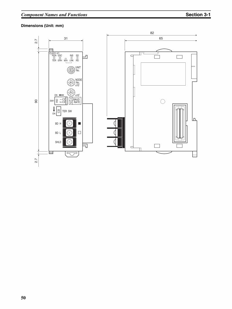
Component Names and Functions Section 3-1
Dimensions (Unit: mm)
6531
UNIT No.
RUNCLK21-V1
ERC INS
ERH M/A LNK RD
902.
72.
7
NODE No.x101
x100
0123456789ABCDEF
0
TER
SD
1 2 3 4 567890 1
2 3 4 56789
BAUD RATE
12
ON
SW1
ONTER SW
BD H
BD L
SHLD
82
ON
12
50

Component Names and Functions Section 3-1
3-1-3 C200HX/HG/HE Controller Link Unit
Wired Unit Indicators
1
Indicators
LED indicators that display the Unit and network status.
Node address switches
Two rotary switches. The node address of the Unit on theController Link Network is set in 2-digit decimal.
Baud rate and operating level settings
A four-pin DIP switch. The following settings are made.
Pins 1, 2: Baud ratePin 3: Not used (leave set to OFF)Pin 4: Operating level
Bus Connection Unit Connector
Connector used for connection to the CPU Unit.
Terminal block for the communications cable
Terminals to connect to the Controller Link Network communicationscable (twisted-pair cable).
Terminating resistance switch (underneath the Unit)
A slide switch. Use this switch to set the terminating resistance to ON for nodes at both ends of the Controller Link Network.
CLK21
NODE NO.
X101 X100
SW1ON
BD H
BD L
SHLD
RUNERCINSSD
TERERHM/ALNKRD
TERSW
#0, #1
12
34
RSV
BAUD RATE
0 1
ON
23
4
(Refer to pages 51, 274)
(Refer to page 96)
(Refer to page 97)
(Refer to page 61)
(Refer to page 68)
(Refer to page 98)
Name Color Status Meaning
RUN (operating)
Green Lit Unit operating normally.
Not lit Unit error.
TER (terminating resistance)
Yellow Lit Terminating resistance switch ON.
Not lit Terminating resistance switch OFF.
ERC (communica-tions error)
Red Lit Communications error, node address setting error (same address set twice), or hardware error.
Not lit Normal operation
ERH (PLC error)
Red Lit PLC error, PLC interface error, EEPROM error, or PLC model setting error.
Not lit No error.
INS (network participation)
Yellow Lit Unit is participating (inserted) in the net-work.
Not lit Unit is not participating (inserted) in the network.
M/A (data link mode)
Yellow Lit Manual (see note)
Note: M/A is always not lit when data links are not active in the network.
Not lit Automatic
LNK (data link)
Yellow Lit Data links participating.
Flashing Error in data link table.
Not lit Not in a data link or data link inactive.
SD (send)
Yellow Lit Data transmission.
Not lit No data transmission.
51

Component Names and Functions Section 3-1
Note Even when the local node does not participate in the data link, theindicator will be lit if there are manually set data links active on thenetwork.
For details refer to 9-1 Troubleshooting Using Indicators.
Dimensions (Unit: mm)
RD (receive)
Yellow Lit Data reception.
Not lit No data reception.
Name Color Status Meaning
1
CLK21
NODE NO.
X101 X100
SW1ON
BD H
BD L
SHLD
RUNERCINSSD
TERERHM/ALNKRD
TERSW
#0, #1
12
34
RSV
BAUD RATE
0 1
ON
23
4
125
15
32
130
34.5
52

Component Names and Functions Section 3-1
3-1-4 CVM1 and CV-series Controller Link Unit
Wired Unit Indicators
Unit number switches
Two rotary switches. The unit number is set in 2-digit decimalfor the Network to which the PLC is connected.
Indicators
LED indicators that display the Unit and network status.
Node address switches
Two rotary switches. The node address of the Unit on theController Link Network is set in 2-digit decimal.
Baud rate switch
A four-pin DIP switch. The following setting is made.Pins 1, 2: Baud ratePins 3, 4: Not used (always OFF)
Terminal block for the communications cable
Terminals to connect to the Controller Link Network communicationscable (twisted-pair cable).
Terminating resistance switch
A slide switch. Use this switch to set the terminating resistance to ON fornodes at both ends of the Controller Link Network.
CLK21
X101
X100
SW1
ON
BDH
BDL
SHLD
RUNERC
TERERH
TER SW
1234
BAUD RATE
BAUD RATE
0 0
INSSD
M/ALNKRD
X100
NODENO.X101
RSV
10
BIT2 BIT1 RATE
RSV
OFFOFFON
OFFONOFF
2MBP1MBP500KBP
UNITNO.X101
(Refer to pages 53, 285)
(Refer to page 100)
(Refer to page 100)
(Refer to page 101)
(Refer to page 101)
(Refer to page 68)
Name Color Status Meaning
RUN (operating)
Green Lit Unit operating normally.
Not lit Unit error.
TER (terminating resistance)
Yellow Lit Terminating resistance switch ON.
Not lit Terminating resistance switch OFF.
ERC (communica-tions error)
Red Lit Communications error, node address setting error (same address set twice), or hardware error.
Not lit Normal operation
ERH (PLC error)
Red Lit PLC error, PLC interface error, EEPROM error, unit number error, or I/O table not set
Not lit No error.
INS (network participation)
Yellow Lit Unit is participating (inserted) in the net-work.
Not lit Unit is not participating (inserted) in the network.
M/A (data link mode)
Yellow Lit Manual (see note)
Note: M/A is always not lit when data links are not active in the network.
Not lit Automatic
LNK (data link)
Yellow Lit Data links participating.
Flashing Error in data link table.
Not lit Not in a data link or data link inactive.
53

Component Names and Functions Section 3-1
Note Even when the local node does not participate in the data link, theindicator will be lit if there are manually set data links active on thenetwork.
For details refer to 9-1 Troubleshooting Using Indicators.
Dimensions (Unit: mm)
SD (send)
Yellow Lit Data transmission.
Not lit No data transmission.
RD (receive)
Yellow Lit Data reception.
Not lit No data reception.
Name Color Status Meaning
RSVRSV
BAUD RATE
UNITNO.X101
2MBP1MBP500KBP
CLK21
X100
SW1
ON
BD H
BD L
SHLD
RUNERC
TERERH
TER SW
1234
BAUD RATE
0 0
INSSD
M/ALNKRD
X100
NODENO.X101 10
BIT2 BIT1 RATE
OFFOFFON
OFFONOFF
15
42
250
9534.5
54

Component Names and Functions Section 3-1
3-1-5 CQM1H-series Controller Link Unit
Wired Unit Indicators
Indicators
LED indicators that display the Unit and network status.
Node address switches
Two rotary switches. The node address of the Unit on theController Link Network is set in 2-digit decimal. Baud rate switch
Terminal block for the communications cable
Terminals to connect to the Controller Link Network communicationscable (twisted-pair cable).
Terminating resistance switch
A slide switch. Use this switch to set the terminating resistance to ON forthe nodes at both ends of the Controller Link Network.
bit/s
k
(Refer to pages 55, 274)
(Refer to page 103)
(Refer to page 103)
(Refer to page 104)
(Refer to page 68)
Name Color Status Meaning
RUN (operating)
Green Lit Unit operating normally.
Not lit Unit error.
TER (terminating resistance)
Yellow Lit Terminating resistance switch ON.
Not lit Terminating resistance switch OFF.
ERC (communica-tions error)
Red Lit Communications error, node address setting error (same address set twice), or hardware error.
Not lit Normal operation
ERH (PLC error)
Red Lit PLC error, PLC interface error, or EEPROM error
Not lit No error.
INS (network participation)
Yellow Lit Unit is participating (inserted) in the net-work.
Not lit Unit is not participating (inserted) in the network.
M/A (data link mode)
Yellow Lit Manual (see note)
Note: M/A is always not lit when data links are not active in the network.
Not lit Automatic
LNK (data link)
Yellow Lit Participating in data links.
Flashing Error in data link tables.
Not lit Not in a data link or data link inactive.
SD (send)
Yellow Lit Data transmission.
Not lit No data transmission.
RD (receive)
Yellow Lit Data reception.
Not lit No data reception.
55

Component Names and Functions Section 3-1
Note Even when the local node does not participate in the data link, theindicator will be lit if there are manually set data links active on thenetwork.
For details refer to 9-1 Troubleshooting Using Indicators.
Dimensions (Unit: mm)
3-1-6 Wire-to-Wire Repeater Unit
32
110
122.8
15.8
k
bit/sON
12
O N1
2
DC24VINPUT
SL1
SL2
T/R2
T/R1
PWR
CS1W-RPT01
BD L
SHLD
BD H
BD L
SHLD
BD H
TER SW
ONON
SW1
BAUDRATE
12
TER SW
+
−
SL1 Terminal Block for Communications CableTerminals to connect to the Controller Link Network communications cable (twisted-pair cable).
Baud rate switch
Power Terminal BlockTerminals to connect to the power supply (24 V DC) that drives the Repeater Unit.
IndicatorsLED indicators that display the status of the Unit and communications.
Terminating Resistance Switch for SL1Turn ON this switch when the Repeater Unit is connected to the SL1 communications cable terminal block at either end of the Controller Link Network.
Terminating Resistance Switch for SL2Turn ON this switch when the Repeater Unit is connected to the SL2 communications cable terminal block at either end of the Controller Link Network.
SL2 Terminal Block for Communications CableTerminals to connect to the Controller Link Network communications cable (twisted-pair cable).
56
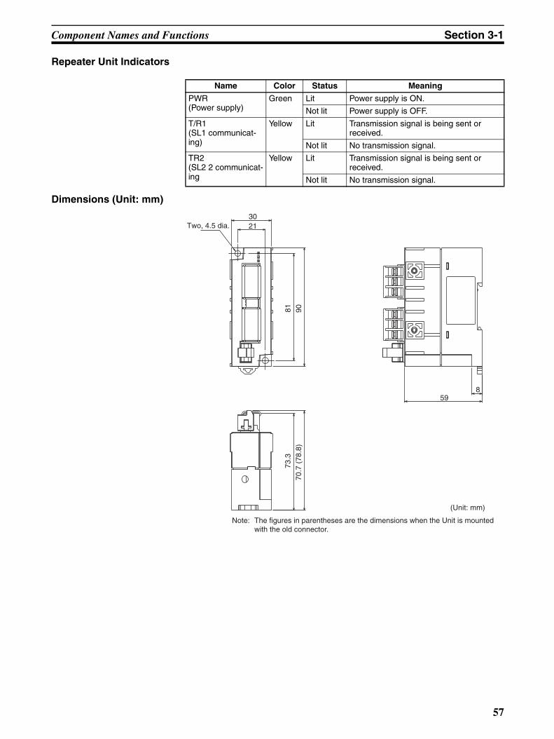
Component Names and Functions Section 3-1
Repeater Unit Indicators
Dimensions (Unit: mm)
Name Color Status Meaning
PWR(Power supply)
Green Lit Power supply is ON.
Not lit Power supply is OFF.
T/R1(SL1 communicat-ing)
Yellow Lit Transmission signal is being sent or received.
Not lit No transmission signal.
TR2(SL2 2 communicat-ing
Yellow Lit Transmission signal is being sent or received.
Not lit No transmission signal.
859
70.7
(78
.8)
73.3
Two, 4.5 dia.30
90
21
81
(Unit: mm)
Note: The figures in parentheses are the dimensions when the Unit is mounted with the old connector.
57

Component Names and Functions Section 3-1
3-1-7 Wire-to-Optical (H-PCF) Repeater Unit
Repeater Unit IndicatorsON
12
O N1
2
DC24VINPUT
SL1
SL2
T/R2
T/R1
PWR
CS1W-RPT02
BD L
SHLD
BD H
TER SW
ONON
SW1
BAUDRATE
12
+
−
SL1 Terminal Block for Communications CableTerminals to connect to the Controller Link Network communications cable (twisted-pair cable).
Baud rate switch
Power Terminal BlockTerminals to connect to the power supply (24 V DC) that drives the Repeater Unit.
IndicatorsLED indicators that display the status of the Unit and communications.
Terminating Resistance Switch for SL1Turn ON this switch when the Repeater Unit is connected to the SL1 communications cable terminal block at either end of the Controller Link Network.
Optical Connector SL2Connects to communications cable (H-PCF optical fiber cable) of the Controller Link Network.
Name Color Status Meaning
PWR(Power supply)
Green Lit Power supply is ON.
Not lit Power supply is OFF.
T/R1(SL1 communicat-ing)
Yellow Lit Transmission signal is being sent or received.
Not lit No transmission signal.
TR2(SL2 2 communicat-ing)
Yellow Lit Transmission signal is being sent or received.
Not lit No transmission signal.
58

Component Names and Functions Section 3-1
Dimensions (Unit: mm)
3-1-8 Wire-to-Optical (GI) Repeater Unit
70.7
(78
.8)
73.3
859
Two, 4.5 dia.
30
90
21
81
(Unit: mm)
Note: The figures in parentheses are the dimensions when the Unit is mounted with the old connector.
ON1
2
O N1
2
DC24VINPUT
SL1
SL2
T/R2
T/R1
PWR
CS1W-RPT03
BD L
SHLD
BD H
TER SW
ONON
SW1
BAUDRATE
12
+
−
SL1 Terminal Block for Communications CableTerminals to connect to the Controller Link Network communications cable (twisted-pair cable).
Baud rate switch
Power Terminal BlockTerminals to connect to the power supply (24 V DC) that drives the Repeater Unit.
IndicatorsLED indicators that display the status of the Unit and communications.
Terminating Resistance Switch for SL1Turn ON this switch when the Repeater Unit is connected to the SL1 communications cable terminal block at either end of the Controller Link Network.
Optical Connector SL2Connects to communications cable (GI optical fiber cable) of Controller Link Network.
59
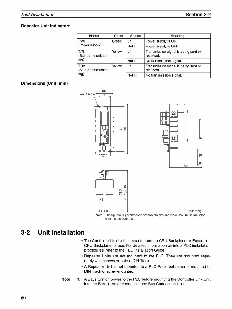
Unit Installation Section 3-2
Repeater Unit Indicators
Dimensions (Unit: mm)
3-2 Unit Installation• The Controller Link Unit is mounted onto a CPU Backplane or Expansion
CPU Backplane for use. For detailed information on into a PLC installationprocedures, refer to the PLC Installation Guide.
• Repeater Units are not mounted to the PLC. They are mounted sepa-rately with screws or onto a DIN Track.
• A Repeater Unit is not mounted to a PLC Rack, but rather is mounted toDIN Track or screw-mounted.
Note 1. Always turn off power to the PLC before mounting the Controller Link Unitinto the Backplane or connecting the Bus Connection Unit.
Name Color Status Meaning
PWR(Power supply)
Green Lit Power supply is ON.
Not lit Power supply is OFF.
T/R1(SL1 communicat-ing)
Yellow Lit Transmission signal is being sent or received.
Not lit No transmission signal.
TR2(SL2 2 communicat-ing)
Yellow Lit Transmission signal is being sent or received.
Not lit No transmission signal.
70.7
(78
.8)
73.3
859
Two, 4.5 dia.(30)
90
21
81
(Unit: mm)Note: The figures in parentheses are the dimensions when the Unit is mounted with the old connector.
60

Unit Installation Section 3-2
2. Be sure that all screws on the Backplane, the Bus Connection Unit, the ter-minal block, and cables are tightened firmly. If screws work loose, a mal-function may occur as a result of vibration.
3. A label has been placed over the upper surface of the Controller Link Unitto prevent scraps of wire from entering the Unit. Conduct wiring and instal-lation with this label in place. If wire scraps get into the Unit, it will malfunc-tion.
4. Remove the label after wiring and installing the Controller Link Unit to pre-vent overheating. Overheating will cause the Unit to malfunction.
3-2-1 Mounting Controller Link Units
C200HX/HG/HE PLCsUp to two C200HX/HG/HE Controller Link Units can be mounted on the CPURack. Controller Link Units cannot be mounted to an Expansion I/O Rack or aSlave Rack.
Note Tighten the screws on the Backplane to a torque of 1.2 N·m.Tighten the screws on the Bus Connection Unit to a torque of 0.4 N·m.
Installing One Controller Link UnitMount the Unit in the slot on the left of the CPU Unit.
Installing Two Controller Link UnitsMount the Units in the two slots on the left of the CPU Unit.
C200HW-CE001 Bus Connection Unit (For one Unit)
Controller Link UnitCPU UnitCPU Backplane
C200HW-CLK21 Controller Link Unit
CPU Unit (C200HE-CPU32/42-(Z)EC200HG-CPU33/43/53/63-(Z)EC200HX-CPU34/44/54/64-(Z)E
C200HW-COM01/04 Communications Board
Controller Link UnitController Link Unit
CPU UnitCPU Backplane
C200HW-CE002 Bus Connection Unit (For two Units)
C200HW-CLK21 Controller Link Unit
CPU Unit(C200HE-CPU32/42-(Z)EC200HG-CPU33/43/53/63-(Z)EC200HX-CPU34/44/54/64-(Z)E
C200HW-COM01/04 Communications Board
61

Unit Installation Section 3-2
Installing with Another Communications UnitWhen installing a Controller Link Unit along with another CommunicationsUnit, such as a SYSMAC LINK Unit or a SYSMAC NET LINK Unit mount bothUnits in the 2 slots on the left of the CPU Unit.
Installing with a PC Card UnitWhen installing a Controller Link Unit along with a PC Card Unit, mount theController Link Unit in the first slot on the left of the CPU Unit. Use theC200HW-CE012 Bus Connection Unit.
CVM1 and CV-series PLCsUp to four Controller Link Units for CVM1 and CV-series PLCs can beinstalled in a CPU Backplane or a Expansion CPU Rack (including both Opti-cal and Wired Units). Controller Link Units cannot be installed on an Expan-sion I/O Rack, a SYSMAC BUS Slave Rack, or a SYSMAC BUS/2 SlaveRack.
The CVM1 and CV-series Controller Link Unit is classified as a CPU Bus Unitand must be mounted in a CPU bus slot.
Note Tighten the screws on the Backplane to a torque of 1.2 N·m.Tighten the fixed screws on the CPU Unit to a torque of 0.9 N·m.
Install the Controller Link Unit in one slot and the other Unit in the other slot.
Other Communications Unit
CPU UnitCPU Backplane
C200HW-CE002 Bus Connection Unit (For two Units)
C200HW-CLK21 Controller Link Unit
CPU Unit(C200HE-CPU32/42-(Z)EC200HG-CPU33/43/53/63-(Z)EC200HX-CPU34/44/54/64-(Z)E
C200HW-COM01/04 Communications Board
Controller Link UnitPC Card Unit
CPU Unit
C200HW-CE012 Bus Connection Unit
C200HW-CLK21 Controller Link Unit
CPU Unit(C200HE-CPU32/42-(Z)EC200HG-CPU33/43/53/63-(Z)EC200HX-CPU34/44/54/64-(Z)E
C200HW-COM01/04 Communications Board
C200HW-PCU01 PC Card Unit
62

Unit Installation Section 3-2
CS-series PLCsUp to a total of eight Controller Link Units with unit version 1.2 or later (wired,optical, and optical ring) for CS-series PLCs (or up to four pre-Ver. 1.2 Con-troller Link Units) can be installed in a CPU Backplane or a CS ExpansionRack. Controller Link Units cannot be installed on an C200H Expansion I/ORack or a SYSMAC BUS Slave Rack.
Note Tighten the screws on the Backplane to a torque of 0.9 N·m.Tighten the fixed screws on the CPU Unit to a torque of 0.4 N·m.
CPU Backplane
Expansion Backplane
2/3/5/8/10 slots
3/5/8/10 slots
CPU Unit
Of these slots, installation is possible in up to 8 slots (unit Ver. 1.2 or later). Installation in up to 4 slots is possible for pre-Ver. 1.2 Units.
CPU Rack (CV500/CV1000/CV2000/CVM1)The Unit can be mounted to the 3/5/10 slots shown in the diagram on the right. (It cannot be mounted to the leftmost slot even if an Expansion CPU Rack is not used.)
Install in four of these 14, 16, or 21 slots.
CPU BackplaneCV500-BC101, CVM1-BC103/CV500-BC051, CVM1-BC053/CV500-BC031
I O C
C P U
P S
3/5/10 slots
Expansion CPU RackCV500/BI111
I O I F
P S
Expansion CPU RackAny of the 11 slots shown in the illustration can be used. The leftmost slot cannot be used.
I O I F
P S
Expansion I/O RackController Link Units cannot be mounted to Expansion I/O Racks.
11 slots
PS: Power Supply UnitCPU: CPU UnitIOC: I/O Control UnitIOIF: I/O Interface Unit
63

Unit Installation Section 3-2
Note When installing several CS-series CPU Bus Units at the same time, a total of16 CS-series CPU Bus Units maximum may be installed.
When connecting multiple Controller Link Units to the CPU Unit, consider thecurrent consumption of the CPU Unit and each CPU Bus Unit before selectingthe Power Supply Unit. For details on Controller Link Unit current consump-tion, refer to Controller Link Unit Models and PLCs on page 18. For details oncurrent consumption of each Unit, refer to the SYSMAC CS Series Program-mable Controllers Operation Manual (W339).
The following table provides an example of current consumption
Example: Using the C200HW-PA204 Power Supply Unit supplying a maxi-mum current of 4.6 A (5 V) and maximum power of 30 W.
CJ-series PLCsA total of up to eight Controller Link Units (unit version 1.2 or later) for CJ-series PLCs can be connected in a CPU Rack or Expansion Rack. (A total of
CPU RackThe Unit can be mounted to the 2/3/5/8/10 slots shown in the diagram on the right.
CPU BackplaneCS1W-BC103, CS1W-BC083, CS1W-BC053, CS1W-BC033, CS1W-BC023
2/3/5/8/10 slots
CS Expansion Backplane
CS Expansion BackplaneSlots 3/5/8/10 shown in the illustration can be used.
C200H Expansion I/O BackplaneController Link Units cannot be mounted to Expansion I/O slots.
3/5/8/10 slots
PS: Power Supply Unit
CPU: CPU Unit
CS1W-BI103, CS1W-BI083, CS1W-BI053, CS1W-BI033
C200H Expansion I/O Backplane
Of these slots, installation is possible in up to 8 slots (unit Ver. 1.2 or later). Installation in up to 4 slots is possible for pre-Ver. 1.2 Units.
Name Model Current consumption per Unit (A)
Number of Units
Current consumption (A)
CPU Backplane (8 slots) CS1W-BC083 0.11 A 1 0.11 A
CPU Unit CS1H-CPU67H 0.82 A 1 0.82 A
Controller Link Unit (Optical) CS1W-CLK21-V1 0.33 A 8 2.64 A
Total 3.57 (power consump-tion: 17.85 W)
64

Unit Installation Section 3-2
up to four Pre-Ver. 1.2 models can be connected.) Be sure to secure the Unitswith the top and bottom sliders.
Note When installing several CJ-series CPU Bus Units at the same time, a total of16 CJ-series CPU Bus Units maximum may be installed.
When connecting multiple Controller Link Units to the CPU Unit, consider thecurrent consumption of the CPU Unit and each CPU Bus Unit before selectingthe Power Supply Unit. For details on Controller Link Unit current consump-tion, refer to Controller Link Unit Models and PLCs on page 18. For details oncurrent consumption of each Unit, refer to the SYSMAC CJ Series Program-mable Controllers Operation Manual (W393).
The following table provides an example of current consumption
Example: Using the CJ1W-PA205R Power Supply Unit supplying a maximumcurrent of 5.0 A (5 V) and maximum power of 25 W.
PS
CPU
IC
PS
II
PS
II
PS
II
Of these slots, installation is possible in up to 8 slots (unit Ver. 1.2 or later). Installation in up to 4 slots is possible for pre-Ver. 1.2 Units.
CPU Rack
CJ-series Expansion Rack
10 Unit max.
End Cover
CJ-series Expansion Rack
10 Unit max.
End Cover
CJ-series Expansion Rack
10 Unit max.
End Cover
10 Unit max.End Cover
PS: Power Supply UnitCPU: CPU UnitIC: I/O Control UnitII: I/O Interface Unit
Name Model Current consumption per Unit (A)
Number of Units
Current consumption (A)
CPU Unit CJ1W-CPU66H 0.99 A 1 0.99 A
Controller Link Unit (Optical) CJ1W-CLK21-V1 0.35 A 8 2.8 A
Total 3.79 (power consump-tion: 18.95 W)
65

Unit Installation Section 3-2
CQM1H-series PLCsOnly one Controller Link Unit can be connected in a CQM1H-series PLC.Connect the Controller Link Unit to the left side of the CPU Unit and then con-nect the Power Supply Unit to the left of the Controller Link Unit.
After the Units have been connected, secure them with the slide locks on thetop and bottom of the Units.
Note The CQM1H-CLK21 Controller Link Unit can be connected only to theCQM1H-CPU51/61 CPU Unit. It cannot be connected to the CQM1H-CPU11/21 CPU Unit.
3-2-2 Mounting a Repeater UnitRepeater Units can be either mounted on a DIN Track or screw-mounted.
CPU Backplane
Expansion CPU Backplane
3/5/10 slots
11 slots
CPU Unit
Of these 14, 16, or 21 slots, installation is possible in up to 4 slots.
Power Supply Unit
CQM1H-CLK21 Controller Link Unit
CQM1H-CPU51/61CPU Unit
66

Unit Installation Section 3-2
Screw-mounting a Repeater UnitUse M4 × 15 screws to mount the Unit as shown in the following diagram.
Mounting a Repeater Unit on DIN Track
1,2,3... 1. Unlock the DIN Track mounting pins located on the rear of the RepeaterUnit.
2. Attach the Repeater Unit by hooking it onto the DIN Track from above (1)and then pressing it into place (2).
3. Lock all DIN Track mounting pins.
4. Secure the Repeater Unit by mounting one End Plate on each side of theUnit. End Plates are attached by hooking first the bottom (1) then the topof the Plate onto the DIN Track and pulling down (2). Use the screw on theeach End Plate to fasten it in place.
DIN TrackMount the Repeater Unit to DIN Track. Use at least three screws to attach theDIN Track to the control panel.
DIN Track: PFP-50N (50 cm), PFP-100N (100 cm), PFP-100N2 (100 cm)
The DIN Track should be attached within the control panel using M4 screwsspaced not more than 210 mm (not more than 6 holes) apart. Attach a DINTrack in at least 3 points for the longest DIN Track length. Tightening torqueshould be 1.2 N·m.
8 mm
81 mm
Two, M4
21 mm
DIN Track mounting pin
67

Wiring Section 3-3
End Plate: PFP-M (2 Plates required per Repeater Unit)
3-3 Wiring
3-3-1 Communications CablesUsing the specified twisted-pair cable, connect all nodes using the multidropmethod.
Communications CablesThe following shielded twisted-pair cables should be used for Controller LinkNetwork connections.
Note 1. Use the specified cable only.
2. Keep communications cables separated from power lines or a high-tensionlines to prevent influences from electronic noise.
PFP-100N2
PFP-100N/50N
BD
BD
SHLD
H
L
g
#
Controller Link Unit
Terminating resistance switch (ON)
Terminating resistance switch (ON)
Terminating resistance switch (OFF)
Terminating resistance switch (OFF)
Model Manufacturer
Li2Y-FCY2 x 0.56 qmm Kromberg & Schubert, Komtec Department
1 x 2 x AWG – 20PE + Tr.CUSN + PVC Draka Cables Industrial
#9207 Belden
ESVC 0.5 x 2 C Bando Densen Co.
ESNC0.5X2C-99-087B Japan Electric Wire & Cable Co.
ESPC 1P x 0.5 mm2 Nagaoka Electric Wire Co., Ltd.
68

Wiring Section 3-3
3. Do not connect the shield cable of the communications cable to a groundthat is also being used for power-system devices, such as inverters.
4. Ground the shield line of the communications cable at one end of the net-work. Do not ground the shield at both ends.
5. Do not run wiring outdoors. If outdoor wiring is necessary, take protectivemeasures against lightning, such as underground wiring or wiring insidepipes.
6. The minimum length of the communications cable between nodes is 1 m.Prepare the communications cables at a length of 1 m or more.
7. Use the multidrop method for connecting nodes. Normal communicationswill not be possible with T branches.
8. Turn ON the terminating resistance switch at the nodes at both ends of thenetwork to connect terminating resistance. Turn OFF the terminating resis-tance switch at all other nodes.
9. A label has been placed over the upper surface of the Controller Link Unitto prevent scraps of wire from entering the Unit. Conduct wiring and instal-lation with this label in place. If wire scraps get into the Unit, it will malfunc-tion (C200HW-CLK21, CS1W-CLK21-V1, CS1W-CLK23, CJ1W-CLK21-V1, CJ1W-CLK23, and CQM1H-CLK21 only).
10. Remove the label after wiring to avoid overheating. Overheating will causethe Unit to malfunction (C200HW-CLK21, CS1W-CLK21-V1, CS1W-CLK23, CJ1W-CLK21-V1, CJ1W-CLK23, and CQM1H-CLK21 only).
Connecting the Shield LineConnect both ends of the shield line to the terminal blocks and earth the ter-minal block at the one end of the network.
Terminal Block Connections
Not Unit a Relay Terminal Block
Note Use the recommended crimp terminals when connecting the cable’s signallines or shield line to the terminal blocks. Short circuits can damage the Units.
BD
BD
SHLD
H
L
g
#
TER SW↓ON
BD H
BD L
SHLD TERSW
↓ON
↓ON
BD H
BD L
SHLD
TER SW
BD H
BD L
SHLD
C200HW-CLK21 (End node)
Terminating resistance (ON)
Ground
Terminating resistance (OFF)
CVM1-CLK21
Terminating resistance (ON)
CS1W-CLK23 CJ1W-CLK23 (End node)
69

Wiring Section 3-3
Using a Relay Terminal Block
Note 1. Mounting and dismounting during communications is not possible for Re-lay Terminal Blocks connected to the nodes at the ends of the network (i.e.:the nodes with terminating resistance).
2. Use the recommended crimp terminals when connecting the cable’s signallines or shield line to the terminal blocks. Short circuits can damage theUnits.
Connecting the Communications CablesUse crimp terminals when connecting communications cables to a ControllerLink Unit. Use the following procedure to connect communications cables to aterminal block.
1,2,3... 1. Peel back the cover of the cable for about 50 mm without scratching themesh of the shield. Do not peel too much because it may cause a short-circuit.
2. Twist the mesh of the shield to form a line.
3. Leave the tip of the wire created by twisting the shield exposed and coverthe remaining section with a heat-shrinking tube.
4. Remove enough of the cover from the signal lines to allow the crimp termi-nals to be connected, taking care not to damage the signal lines. Damageto the signal lines could cause the cable to break.
TER SW↓ON
BD H
BD L
SHLD TERSW
↓ON
↓ON
BD H
BD L
SHLD
TER SW
BD H
BD L
SHLD
C200HW-CLK21 (End node)
Terminating resistance (ON)
Ground
Terminating resistance (OFF)
CVM1-CLK21
Terminating resistance (ON)
CS1W-CLK23 CJ1W-CLK23 (End node)
Relay Terminal Block (see note 1.)
Approx. 50 mm
Wire created by twisting the shield
Cover with a heat-shrinking tube
Exposed portion for crimp terminal connection
70

Wiring Section 3-3
5. Twist firmly the portion of the signal lines that are exposed.
6. Apply vinyl tape or heat-shrinking tube to the end of the cover that waspeeled in step 1.
7. Mount the crimp terminal onto the signal lines and the shield line.Use M3 crimp terminals, as illustrated below.
8. Connect the signal lines and the shield line to the terminal block using themarkings on the terminal block.
Note a) You can change the length of the signal lines as shown in the fol-lowing diagrams to make wiring a lot easier.
Apply vinyl tape or a heat-shrinking tube.
6.2 mm max. 6.2 mm max.
Shield line
Communications cable from the previous node
Communications cable to the next node
Communications dataHigh signal
Communications dataLow signal
Approx. 30 mm
Approx. 50 mm
Approx. 40 mm
71

Wiring Section 3-3
b) The approximate dimension for when the cable has been wiredfrom the terminal block along the front of the Unit is shown in thefollowing diagram.
Note 1. Always turn OFF the power to the PLC before connecting the communica-tions cables.
2. Always use a crimp terminal for wiring. If a wire that has only been twistedis connected directly to a terminal block, short circuit, malfunction andproduct damage will result.
3. Use the recommended crimp terminals.4. When mounting the crimp terminal, always use the appropriate tools for
each crimp terminal and follow the appropriate installation procedures.Contact the crimp terminal manufacturer for details on the appropriatetools and procedures. Failure to use the appropriate tools and procedurescould cause cables to break.
5. Measure the length of peeled cable during installation according to thecrimp terminal used and make sure that the peeled length is not too long.Cover the compressed section of the crimp terminal and cable with vinyltape or heat-shrinking tube.
6. Be sure not to confuse the signal lines and shield line connections.7. Tighten the screws on the terminal block firmly. The correct tightening
torque is 0.5 N·m.8. If a signal line disconnects from the terminal, either the Unit will be unable
to communicate with other nodes on the network or that section of the net-work will be isolated from other nodes. Be sure not to pull on the signallines.
9. Do not pull on a communication cable.
25 mm max.
Transmission not possible
Isolated(Transmission not possible)
Controller Link Unit
72

Wiring Section 3-3
10. When bending a communications cable, allow 60 mm or more for the bend-ing radius (R).
11. Do not place any object on the communications cable.
12. Supply power only after checking the wiring thoroughly.
13. Connect the terminal block only after checking it thoroughly.
14. Marks are provided on the terminal block for the signal lines. Connect thesignal lines according to the marks. The marks correspond to signal linesas listed below.
3-3-2 Repeater Units
Power Supply WiringRepeater Units must be supplied with DC power. The procedure for wiring thepower supply is the same for all Repeater Units (CS1W-RPT01/02/03).
Use the following procedure to wire the power supply to Repeater Units.
1,2,3... 1. Attach the following crimp terminal to each of the two power lines.
Crimp terminal: AI Series manufactured by Phoenix Contact
The following specialized tool is available for this purpose:ZA3 manufactured by Phoenix Contact
2. Insert the crimp terminals on the positive and negative power lines into theorange power connectors located near the bottom of the front panel of theRepeater Unit. Insert the positive line in the top and the negative line in thebottom.
3. Use a small, flat-blade screwdriver to fasten the crimp terminals in place.
Note 1. Supply power to the Repeater Unit using a power supply installed specifi-cally for the Repeater Unit. Do not supply power to the Repeater Unit froman I/O power supply, motor power supply, or control power supply.
2. To prevent the power supply from being affected by noise, wire and installthe power supply away from power lines and high-voltage lines.
3. Attach special-purpose crimp terminals to the power cables.
4. Do not connect the positive and negative lines to the wrong connectors.
5. The power cable screws should be fastened to a tightening torque of0.2 N·m.
6. Do not pull on the power cable.
7. Do not bend the power cable past its natural bending radius.
Mark Signal name Line colorg BDH (communications data high) Black
@ BDL (communications data low) White
None SHLD (shield) ---
Crimp terminal Cable
Insert the cable and then crimp the terminal.
73

Wiring Section 3-3
8. Do not place any object on the power cable.
9. Check that connectors are correctly attached before using the Unit.
Power Supply SpecificationsThe power supply to the Repeater Unit must meet the following specifications.
The following Power Supply Unit is recommended:
OMRON S82K Series
Laying Optical Cable (CS1W-RPT02/03 Only)Optical fiber cable (H-PCF or GI) can be used to create an optical connectionin part of a wired network.
CS1W-RPT02 (H-PCF)
Note 1. Always use the specified Optical Fiber Cables.
2. The maximum distance between nodes depends on how the cable is con-nected. For details, refer to the applicable Optical Fiber Cable (H-PCF)manual.
Connection Procedure Use the following procedure to connect Optical Fiber Cables to a Unit.
1,2,3... 1. Tighten screws in the mounting brackets so that the through-holes on theterminal are on the top and bottom and then affix hexagonal nuts from theopposite side of the terminal.
2. Insert bushing to the mounting bracket and secure the Unit with screws.3. Pass the tension member through the through-holes, and tighten the ter-
minal screws to affix the tension member.4. Affix the cable to the mounting bracket so that it is clamped by the bracket.
Item CS1W-RPT01 Wire-to-Wire
Repeater Unit
CS1W-RPT02 Wire-to-Optical (H-PCF) Repeater Unit
CS1W-RPT03Wire-to-Optical (GI)
Repeater Unit
Power supply volt-age
24 V DC
Allowable power supply voltage range
20.4 to 26.4 V DC (24 V DC, −15% to 10%)
Current consump-tion
24 V DC at 60 mA max.
24 V DC at 60 mA max.
24 V DC at 70 mA max.
Inrush current 2.5 A max. (24 V DC with rise time 5 ms)
Power terminal block
One connector to connect to the power terminal block is pro-vided.
H-PCF cable
SL1
SL2
SL1
SL2
Wired Controller Link Unit
Wired Controller Link Unit
CS1W-RPT02 Repeater Unit
CS1W-RPT02 Repeater Unit
74

Wiring Section 3-3
5. Move the cable connector so that the loose ends are on the left-hand side,and insert the Unit’s optical connector as far as it will reach.
• Insert the connectors completely and always check that the connectorsare locked before starting operation.
Even in token-ring mode, the network will be broken and communications maybe disrupted if disconnections occur at two or more places. Be sure not toallow connectors to be disconnected during communications.
• Do not pull on the Optical Fiber Cable too forcefully.The maximum tension that can be applied to the cord is 10 kg and themaximum tension that can be applied to the cable is 50 kg.
• Do not bend the cable too sharply. The minimum radius for bends is 10 cm.
• To prevent the Optical Fiber Cable from being pulled too forcefully, alwaysuse the cable securing bracket and provide space below the Unit asshown in the following diagram. Do not exceed the maximum tension forthe cord and cable:
Cord: 0 kg (Do not apply any tension.)Cable: 5 kg
• Do not place objects on top of the Optical Fiber Cable. The maximumpressure that can be placed on the cord and cable is as follows:
Cord: 30 kg/10 cmCable: 50 kg/10 cm
• Inspect the connector before installing it.
DC24VINPUT
SL1
SL2
T/R2
T/R1
PWR
CS1W-RPT02
BD L
SHLD
BD H
TER SW
ON
ON
SW1
BAUDRATE
12
+
−
Example: Connections for Duplex Operation of Communications Units
Mounting bracketTension member
Terminal
Cord Cable
Cord Cable
75

Wiring Section 3-3
Communications Cables
Optical Bus or Optical Ring System (H-PCF Cable)
The following devices are required for the Optical Bus or Optical Ring (H-PCF)Controller Link Network. The cable and connectors are the same as thoseused for Optical SYSMAC LINK Networks.
Optical Fiber Cables (Indoor Use Only)
Use the following Optical Fiber Cables (Hard Plastic-clad Fiber: H-PCF).
Note The Optical Fiber Cable model numbers are as follows.
Note 1. Either full-lock or half-lock connectors can be used in a Controller Link Net-work, but we recommend full-lock connectors to prevent accidental discon-nections during operation.
2. The maximum distance between nodes is slightly shorter for connectorswith crimp-cut cables compared to connectors assembled with adhesive.Also, the maximum distance is reduced due to extension loss when InlineAdapters are used to extend cables.
Name Specifications Model
H-PCF cables Black 10 m S3200-HCCB101
50 m S3200-HCCB501
100 m S3200-HCCB102
500 m S3200-HCCB502
1,000 m S3200-HCCB103
Orange 10 m S3200-HCCO101
50 m S3200-HCCO501
100 m S3200-HCCO102
500 m S3200-HCCO502
1,000 m S3200-HCCO103
Name Model Specifications
Connector S3200-COCF2071 Use to connect a cable to a node.(Full-lock connector for crimp-cut cable.)
S3200-COCF2571 Use to connect a cable to a node.(Half-lock connector for crimp-cut cable.)
Inline Adapter S3200-COIAT2000 Use to connect or extend cables.(Use one adapter for each connection.)
S3200-H@@@@@@@Tensioner optionNone: Standard (with tension member)N: Without tension member
Cable length@@@ A B(A/10) x 10B m
Cable colorB: BlackO: Orange
Cable specificationL: With power supply lineC: Without power supply line
TypeB: CordC: Cable
76

Wiring Section 3-3
Optical Fiber Cables with Connectors (Indoor Use Only)
The following Optical Fiber Cables are available with Connectors alreadyattached.
Note 1. Consult a specialist tradesman if cables with outdoor specifications are re-quired.
2. The cables listed above are black and have power supply lines and tensionmembers, although the power supply lines aren’t used in the ControllerLink Network.
3. All of the cables listed above are attached to the connectors with adhesive.
4. Special training is required to assemble Optical Fiber Cables and connec-tors with adhesive.
Optical Fiber Cable Accessories
Use the following accessories to assemble and test Optical Fiber Cables.
This manual does not provide details on Optical Fiber Cable preparation. Fordetails, refer to the instructions provided with the CAK-0057 or the S3200-CAK1062 Assembly Tool.
Specifications Length Model
Optical Fiber Cable Connectors:S3200-COCF2071
⇓S3200-COCF2071
2 m S3200-CN201-20-20
5 m S3200-CN501-20-20
10 m S3200-CN102-20-20
15 m S3200-CN152-20-20
20 m S3200-CN202-20-20
Over 20 m S3200-CN-20-20(Specify length (m) when ordering.)
Optical Fiber Cable Connectors:
S3200-COCF2071⇓
S3200-COCF2571
2 m S3200-CN201-20-25
5 m S3200-CN501-20-25
10 m S3200-CN102-20-25
15 m S3200-CN152-20-25
20 m S3200-CN202-20-25
Over 20 m S3200-CN-20-25(Specify length (m) when ordering.)
Optical Fiber Cable Connectors:S3200-COCF2571
⇓S3200-COCF2571
2 m S3200-CN201-25-25
5 m S3200-CN501-25-25
10 m S3200-CN102-25-25
15 m S3200-CN152-25-25
20 m S3200-CN202-25-25
Over 20 m S3200-CN-25-25(Specify length (m) when ordering.)
Name Model Specifications Manufacturer
Optical Fiber Assembly Tool
CAK-0057 Crimp-cut tool for the S3200-COCF2071/2571 Con-nectors
Sumitomo Electric Industries, Ltd.
Optical Power Tester CAT-2700 With CAT-2702 Head Unit and adapter for the S3200-COCF2071/2571 Connectors
Master Fiber Set CAT-2001H One meter cable for use with the CAT-2702 Head Unit
77

Wiring Section 3-3
CS1W-RPT03 (GI)
Note 1. Always use the specified Optical Fiber Cables.
2. Although the Optical Fiber Cables can be distinguished by the markings orcolor, in order to prevent incorrect connection it is recommended that tagsare attached to the cables.
3. The maximum distance between nodes depends on the type of GI cable(core diameter) that is being used.62.5/125 µm cable: Max. distance between nodes = 2 km50/125 µm cable: Max. distance between nodes = 1 km
Connection Procedure Use the following procedure to connect Optical Fiber Cables to a Unit.
1,2,3... 1. Attach the mounting bracket to the Unit with the provided screws.
2. Attach the clamp to the mounting bracket so that it clamps the cable(s).
3. Remove the Optical Connector Covers from the Unit’s connectors shownin the following diagram if there are covers protecting the connectors.
GI cable
SL1
SL2
SL1
SL2Send
Wired Controller Link Unit
Wired Controller Link Unit
CS1W-RPT03 Repeater Unit
CS1W-RPT03 Repeater Unit
Receive
Send
Receive
Mounting bracket
Clamp
1. Screw the mountingbracket to the Unit.
2. Attach the clamp to the mounting bracket so that the cable(s) are clamped.
78

Wiring Section 3-3
Remove the covers from the tips of the cables’ ST connectors if there arecovers protecting the ST connectors.
Note To replace the Optical Connector Cover, just reverse the steps shownin the diagram above.
4. Turn the cable connector so that the tab in the connector faces left andaligns with the slot in the Unit’s connector. Insert the cable connector fullyinto the Unit’s optical connector. Press and turn the cable’s connectorclockwise to lock the connector in place.
Note To remove the connector, just reverse the steps shown in the diagramabove. (Press and turn the cable connector’s metal fitting counter-clockwise to unlock the connector.)
5. After installing the Optical Fiber Cable, fix the tension member of the Opti-cal Fiber Cable.
Insert the connectors completely and always check that the connectors arelocked before starting operation.
When installing Optical Fiber Cables, be sure to stay within the specifications(e.g., tensile strength, bending, lateral pressure) for the cables used.
Optical Fiber Cables
Use Optical Fiber Cables (Graded Index: GI) with the following optical specifi-cations.
50/125 µm AGF Cable
Optical Connector Cover
Pull off the cover.Rotate the cover 90° counterclockwise.
Slot
Cable connector
Unit's optical connector
Tab
Press and turn the metal fitting on the cable connector until it locks.
Align the tab in the cable connector with the slot in the Unit's connector and fully insert the cable connector.
Item Minimum Standard Maximum Unit Conditions
Numerical Aper-ture (N.A.)
--- 0.21 --- --- Theoretical value
Transmission loss
--- --- 3.0 Lf dB 0.5 km ≤ Lf λ = 0.8 µmTa = 25°C3.0 Lf + 0.2 0.2 km ≤ Lf < 0.5 km
3.0 Lf + 0.4 Lf < 0.2 km
Connection loss --- --- 1.0 λ = 0.8 µm, one location
Transmission bandwidth
500 --- --- MHz⋅km λ = 0.85 µm (LD)
79

Constructing Networks with Repeater Units Section 3-4
Note Lf is fiber length in km, Ta is ambient temperature, and λ is the peak wave-length of the test light source.
62.5/125 µm AGF Cable
Note Lf is fiber length in km, Ta is ambient temperature, and λ is the peak wave-length of the test light source.
Connectors
ST Connector
3-4 Constructing Networks with Repeater UnitsRepeater Units can be used to construct flexible networks such as thoseshown below.
Note 1. Repeater Units must be supplied with 24-V DC power.
2. Wire-to-Optical Repeater Units (CS1W-RPT02 and CS1W-RPT03) areused to convert a section of a wired network to optical fiber. Two Units arealways used as a single set.Wire-to-Optical Repeater Units cannot be connected to Optical Ring/Opti-cal Controller Link Units or Support Boards. If these types of ControllerLink Units or Support Boards are connected by mistake, communicationserrors will occur throughout the network.
3. Repeater Units have a baud rate switch and a terminating resistanceswitch. The same baud rate must be set for all nodes on the network.In addition, the terminating resistance switch of Units (Controller Link
Item Minimum Standard Maximum Unit Conditions
Numerical Aper-ture (N.A.)
--- 0.28 --- --- Theoretical value
Transmission loss
--- --- 3.5 Lf dB 0.5 km ≤ Lf λ = 0.8 µmTa = 25°C3.5 Lf + 0.2 0.2 km ≤ Lf < 0.5 km
3.5 Lf + 0.4 Lf < 0.2 km
Connection loss --- --- 1.0 λ = 0.8 µm, one location
Transmission bandwidth
200 --- MHz⋅km λ = 0.85 µm (LD)
T-Branch Wiring
CS1W-RPT01 Repeater Unit
500 m max.(at 2 Mbit/s)
500 m max.(at 2 Mbit/s)
CS1W-RPT01 Repeater Unit
Long-distance Wiring
CS1W-RPT01 Repeater Unit
62-node Configuration31 nodes max.
31 nodes max. CS1W-RPT02/03 Repeater Unit
Partial Conversion to Optical Cable
Wire cable Wire cable
CS1W-RPT02/03 Repeater Unit
Optical cable
80

Constructing Networks with Repeater Units Section 3-4
Units/Support Boards or Repeater Units) at both ends of each networksegment created by installing Repeaters must also be turned ON.To construct a 62-node configuration in a wired network, all network nodesmust consist of one of the following models:
CS1W-CLK21-V1, CS1W-CLK23, CJ1W-CLK21-V1, CJ1W-CLK23, 3G8F7-CLK21-V1, 3G8F7-CLK23-E.
The following Wired Network 62 Node Enable Bit in the DM ParameterArea software switch on each node must be turned ON to enable using 62nodes maximum:
4. Repeater Units can be connected in a network in advance if new nodes areto be added to the network after the system has been constructed. Whenit becomes necessary to add a node, cabling can be accomplished easilyby simply wiring a T-Branch to the Repeater Unit. This method also allowsnodes to be added without stopping communications over the existing net-work.
3-4-1 SegmentsRepeater Units divide a wired Controller Link network into segments. Seg-ments are comprised of nodes connected in a multi-drop configuration usingwire cables. The specifications of the network within a segment are identicalto the wired Controller Link network itself. The specifications within a singlesegment are shown in the following table.
15 14 13 12 11 10 9 8 7 6 5 4 3 2 1 0− − − − − − − − − − − − − − −
Software switch (D30000+100 × unit number)
Wired Network 62 Nodes Enable Bit0: 32 nodes max.1: 62 nodes max.
Item Specifications within each segment
Remarks
Transmission line type
Multi-drop ---
Baud rate and maxi-mum transmission distance
2 Mbps: 500 m1 Mbps: 800 m500 Kbps: 1 km
Because Repeater Units enable up to 2 stages to be connected, the maximum transmission dis-tance of a network (i.e., the total length of the longest path connect-ing any two nodes) is as follows:
2 Mbps: 1.5 km1 Mbps: 2.4 km500 Kbps: 3 km
Maximum number of nodes (Units)
32, including Controller Link Units, Support Boards, and Repeater Units
Repeater Units do not use a node address.
81

Constructing Networks with Repeater Units Section 3-4
3-4-2 Number of Repeater UnitsThe number of Repeater Units that can be connected in a Wired ControllerLink Network depends on the mode of connection.
When Repeater Units are used, a maximum of 32 Units, including ControllerLink Units/Support Boards and Repeater Units, can be connected within asingle segment.
Moreover, if Repeater Units are used for T-Branch wiring, long-distance wiringor partial conversion to optical fiber, up to two repeater stages (see notebelow) can be connected. Connect Repeater Units so that they do not exceedthese ranges.
Note The maximum number of repeater stages refers to the maximum number ofRepeater Units that can be inserted into the path connecting any two nodes.In other words, it is necessary to connect Repeater Units so that no more thantwo Repeater Units (two stages) need to be passed for any node within a net-work to reach any other node. With Wire-to-Optical Repeater Units, two Unitsmake up a single set, which is counted as a single stage.
Examples of Correct Repeater Unit Connections
T-Branch Wiring: 2-stage Repeater Unit Connection
Not more than 2 Repeater Units (2 stages) must be passed for any node toreach any other node
Wire
Optical fiber cable
: Wire-to-wire Repeater Unit
: Range of a single segment
: Controller Link Unit/Support Board
: Wire-to-optical Repeater Unit (two Units used in a pair)
Note: The Repeater Unit will be counted in the number of nodes for each segment that it is connected to.
Stage 1
Stage 2
CS1W-RPT01 Repeater Unit
82

Constructing Networks with Repeater Units Section 3-4
Long-distance Wiring: 2-stage Repeater Unit Connection
Not more than 2 Repeater Units (2 stages) must be passed for any node toreach any other node
Partial Optical Conversion: 2-stage Repeater Unit Connection
Two Wire-to-Optical Repeater Units make up a single set counted as a singlestage. Therefore, not more than 4 Repeater Units (2 stages) must be passedfor any node to reach any other node.
Examples of Incorrect Repeater Unit Connections
More than 2 Stages of Repeater Units
The path from PLC A to PLC B travels via 3 Repeater Units (3 stages). Thiskind of network is NOT allowed.
More than 2 Stages of Repeater Units
Stage 2
CS1W-RPT01 Repeater Unit
Stage 1 Stage 2Optical fiber cable
CS1W-RPT02 or CS1W-RPT03 Repeater Unit
PLC A
PLC B
CS1W-RPT01 Repeater Unit
CS1W-RPT01 Repeater Unit
83

Constructing Networks with Repeater Units Section 3-4
The path from one node to another travels via three Repeater Units(3 stages). This kind of network is NOT allowed.
Note If the Repeater Units are used incorrectly, communications errors may occur,or nodes may not be able to participate in the network.
3-4-3 Terminating ResistanceIn a Wired Controller Link Network, turn ON the terminating resistanceswitches only at the nodes at both ends of the network.
When Repeater Units are used to divide the network into multiple segments,turn ON the terminating resistance switches of the nodes at both ends of eachsegment. When a Repeater Unit is connected to the end of a segment, turnON the built-in terminating resistance switch of the Repeater Unit itself.
Connection examples are shown below.
T-Branch Wiring
Long-distance Wiring
Terminating resistance: ON
Terminating resistance: ON
Terminating resistance: ON
Terminating resistance: ON
Terminating resistance: ON
Terminating resistance: ON
Segment 1
Segment 2 Segment 3
CS1W-RPT01 Repeater Unit Terminating resistance is turned ON at both ends of
each segment. (Repeater Units are also equipped with a built-in terminating resistance switch.)
Terminating resistance: ON
Terminating resistance: ON
Terminating resistance: ON
Terminating resistance: ON
Terminating resistance: ON Terminating
resistance: ON
Segment 1 Segment 2 Segment 3
CS1W-RPT01 Repeater Unit
84

Constructing Networks with Repeater Units Section 3-4
Partial Conversion to Optical Fiber
Combining T-Branch Wiring (2-stage Repeater) and Partial Optical Fiber
Note When constructing a network using Repeater Units, each segment must sat-isfy all of the following requirements:
• The total number of Controller Link Units, Support Boards, and RepeaterUnits within a single segment must not exceed 32.
• The total cable length of a single segment must not exceed the specifiedvalue. (500 m at 2 Mbps; 800 m at 1 Mbps; and 1 km at 500 Kbps.)
• The maximum number of repeater stages that can be inserted into thepath connecting any two nodes is two.
• The node at each end of a segment (including Repeater Units) must haveterminating resistance turned ON.
• The baud rates within each segment must be set to the same value.
Terminating Resistance: ON
Segment 1 Segment 2
Terminating Resistance: ON
Terminating Resistance: ON
Terminating Resistance: ON
(Optical fiber cable)
Repeater Unit CS1W-RPT02 or CS1W-RPT03
Segment 1
Segment 2
Terminating resistance: ON
CS1W-RPT02 or CS1W-RPT03 Repeater Unit
Terminating resistance: ON
Terminating resistance: ON
Terminating resistance: ON
Terminating resistance: ON
Terminating resistance: ON
Terminating resistance: ON
Terminating resistance: ON
Segment 3
Segment 4
CS1W-RPT01Repeater Unit
85

Constructing Networks with Repeater Units Section 3-4
86

87
SECTION 4Preparations for Communications
This section describes the settings required for starting communications. These basic settings are required for both datalinks function and the message service. Carry out the settings described here before turning on power to the Controller LinkUnit.
4-1 CS-series Controller Link Units . . . . . . . . . . . . . . . . . . . . . . . . . . . . . . . . . . . 88
4-1-1 Overview. . . . . . . . . . . . . . . . . . . . . . . . . . . . . . . . . . . . . . . . . . . . . . 88
4-1-2 Unit Number . . . . . . . . . . . . . . . . . . . . . . . . . . . . . . . . . . . . . . . . . . . 88
4-1-3 Node Addresses . . . . . . . . . . . . . . . . . . . . . . . . . . . . . . . . . . . . . . . . 89
4-1-4 Baud Rates . . . . . . . . . . . . . . . . . . . . . . . . . . . . . . . . . . . . . . . . . . . . 90
4-1-5 Terminating Resistance. . . . . . . . . . . . . . . . . . . . . . . . . . . . . . . . . . . 91
4-2 CJ-series Controller Link Units . . . . . . . . . . . . . . . . . . . . . . . . . . . . . . . . . . . 91
4-2-1 Overview. . . . . . . . . . . . . . . . . . . . . . . . . . . . . . . . . . . . . . . . . . . . . . 92
4-2-2 Unit Number . . . . . . . . . . . . . . . . . . . . . . . . . . . . . . . . . . . . . . . . . . . 92
4-2-3 Node Addresses . . . . . . . . . . . . . . . . . . . . . . . . . . . . . . . . . . . . . . . . 93
4-2-4 Baud Rates . . . . . . . . . . . . . . . . . . . . . . . . . . . . . . . . . . . . . . . . . . . . 94
4-2-5 Terminating Resistance. . . . . . . . . . . . . . . . . . . . . . . . . . . . . . . . . . . 94
4-3 C200HX/HG/HE Controller Link Units . . . . . . . . . . . . . . . . . . . . . . . . . . . . . 95
4-3-1 Overview. . . . . . . . . . . . . . . . . . . . . . . . . . . . . . . . . . . . . . . . . . . . . . 96
4-3-2 Node Addresses . . . . . . . . . . . . . . . . . . . . . . . . . . . . . . . . . . . . . . . . 96
4-3-3 Baud Rates and Operating Levels. . . . . . . . . . . . . . . . . . . . . . . . . . . 97
4-3-4 Terminating Resistance. . . . . . . . . . . . . . . . . . . . . . . . . . . . . . . . . . . 98
4-4 CVM1 and CV-series Controller Link Units. . . . . . . . . . . . . . . . . . . . . . . . . . 99
4-4-1 Overview. . . . . . . . . . . . . . . . . . . . . . . . . . . . . . . . . . . . . . . . . . . . . . 99
4-4-2 Unit Number . . . . . . . . . . . . . . . . . . . . . . . . . . . . . . . . . . . . . . . . . . . 100
4-4-3 Node Addresses . . . . . . . . . . . . . . . . . . . . . . . . . . . . . . . . . . . . . . . . 100
4-4-4 Baud Rates . . . . . . . . . . . . . . . . . . . . . . . . . . . . . . . . . . . . . . . . . . . . 101
4-4-5 Terminating Resistance. . . . . . . . . . . . . . . . . . . . . . . . . . . . . . . . . . . 101
4-5 CQM1H-series Controller Link Units. . . . . . . . . . . . . . . . . . . . . . . . . . . . . . . 102
4-5-1 Overview. . . . . . . . . . . . . . . . . . . . . . . . . . . . . . . . . . . . . . . . . . . . . . 102
4-5-2 Node Addresses . . . . . . . . . . . . . . . . . . . . . . . . . . . . . . . . . . . . . . . . 103
4-5-3 Baud Rates . . . . . . . . . . . . . . . . . . . . . . . . . . . . . . . . . . . . . . . . . . . . 103
4-5-4 Terminating Resistance. . . . . . . . . . . . . . . . . . . . . . . . . . . . . . . . . . . 104
4-6 Repeater Units. . . . . . . . . . . . . . . . . . . . . . . . . . . . . . . . . . . . . . . . . . . . . . . . . 104
4-6-1 Wire-to-Wire Repeater Unit . . . . . . . . . . . . . . . . . . . . . . . . . . . . . . . 105
4-6-2 Baud Rates . . . . . . . . . . . . . . . . . . . . . . . . . . . . . . . . . . . . . . . . . . . . 105
4-6-3 Terminating Resistance. . . . . . . . . . . . . . . . . . . . . . . . . . . . . . . . . . . 106

CS-series Controller Link Units Section 4-1
4-1 CS-series Controller Link UnitsThe following settings are required for a Controller Link Unit used with a CS-series PLC.
4-1-1 Overview
Unit Number
Node Address
Baud Rate
Note Factory default setting is in bold. Always leave pins 3 and 4 OFF.
Terminating Resistance
4-1-2 Unit NumberSet the unit number for each Unit using the rotary switches on the front of theUnit. The unit number is used to identify a CPU Bus Unit within the PLC. Anyunit number can be set between 0 and F in hexadecimal (00 to 15 in decimal)
.
Item Switch Page
Unit number Unit number setting switch 88
Node address Node address switches 89
Baud rate Baud rate, pins 1 and 2 90
Terminating resistance Terminating resistance switch 91
CLK21-V1Setting range Nodes
01 to F (default is 0) All nodes in the Network
Setting range Nodes
01 to 32 (default is 01) All nodes in the Network
Pins Baud rate Maximum transmission
distance
Nodes
Pin 1 Pin 2
OFF OFF 2 Mbps 500 m Set same rate for all nodes in the Network.
ON OFF 1 Mbps 800 m
OFF ON 500 Kbps 1 km
ON ON Cannot be set.
Front switch Terminating resistance
Nodes
OFF (factory default)
Not connected All nodes in the NetworkTurn ON the terminating resis-tance at the nodes at both ends of the Network and turn it OFF at all other nodes.
ON Connected
Note: The factory default settings are shown above.
88

CS-series Controller Link Units Section 4-1
Set the node address using a small flat-blade screwdriver, being careful not todamage the rotary switches.
Note 1. Always turn OFF the PLC’s power before setting the unit number.
2. When setting a Unit for the first time or changing the existing setting, createa I/O table in the PLC’s CPU Unit.
3. Do not set the same unit number twice within the same PLC. An error willoccur if the same unit number is set for two different Unit, and the CPU Unitwill not be able to recognize the Units.
4. When the Unit is recognized by the PLC’s CPU Unit, “NS” will be shown inthe I/O table displayed for the CX-Programmer programming device.
5. The default setting is “0.”
6. The unit number determines the words used by the Controller Link Unit inPLC memory.
4-1-3 Node AddressesSet the node addresses of each Unit on the Network using the rotary switcheson the front of the Unit. The node address is used to identify each node in theNetwork can be set to any number between 01 and 32.
Set the node address using a small flat-blade screwdriver, being careful not todamage the rotary switches.
Note 1. When all of the following conditions are satisfied, node addresses can beset between 01 and 62, and the network can contain up to 62 nodes.
a) All nodes in the Controller Link Network use CS1W-CLK21-V1, CS1W-CLK23, CJ1W-CLK21-V1, or CJ1W-CLK23 Units.
b) The Wired Network 62 Node Enable Bit in the DM Parameter Areasoftware switches (bit 11 of D30000 + 100 × Unit No.) of all nodes isturned ON.
c) At least one CS1W-RPT01 Repeater Unit is connected and the num-ber of nodes in a single segment does not exceed 31.
2. Always turn OFF the PLC’s power before setting the node addresses.
3. Do not set the same node address twice within the same network. An errorwill occur if the same address is set for two different nodes. The ERC indi-cator on the front of the Unit will light (Communications Error Flag) and ei-
Item Specifications
Setting method Single-digit hexadecimal
Setting range 0 to F (decimal 00 to 15, default is 0)
Node All nodes in the Network
Item Specifications
Setting method 2-digit decimal
Setting range 01 to 32 (default is 01) (See note 1.)
Node All nodes in the Network
1's digit
10's digit
Note: The factory default settings are shown above.
89

CS-series Controller Link Units Section 4-1
ther communications will stop, or the INS indicator will not light and you willbe unable to participate in the Network.
4. When CS1W-CLK21-V1, CS1W-CLK23, CJ1W-CLK21-V1, and CJ1W-CLK23 Units are used with other models in the same network, set the nodeaddresses of all nodes between 1 and 32. In a network containing pre-ver-sion-1 models, it is not possible to construct a network that uses a nodeaddress higher than 32.Turn ON the Wired Network 62 Node Enable Bit (bit 11 of D30000 + 100 ×Unit No.) in the DM Parameter Area software switch of all CS1W-CLK21-V1, CS1W-CLK23, CJ1W-CLK21-V1, and CJ1W-CLK23 Units to restrictthe network to 32 nodes maximum. If a different value is specified, the net-work will be incorrectly configured.
5. To construct a network that uses a node address higher than 32, it is nec-essary for all nodes to be CS1W-CLK21-V1, CS1W-CLK23, CJ1W-CLK21-V1, or CJ1W-CLK23 Units.In addition, the Wired Network 62 Node Enable Bit in the DM ParameterArea software switch of all nodes must be turned ON to enable using 62nodes maximum. If a different value is specified, the network will not becorrectly configured.
6. Only node addresses 1 through 32 can be used on networks for which 62nodes have not been enabled.
7. The Wired Network 62 Node Enable Bit in the DM Parameter Area soft-ware switches of CS1W-CLK21-V1, CS1W-CLK23, CJ1W-CLK21-V1, andCJ1W-CLK23 Units is read when the Unit is restarted.
8. The send sequence for the data link areas is determined according to thesequence of node addresses for automatically set data links.
9. Assign node addresses consecutively beginning from 01 whenever possi-ble to minimize Network construction time.
4-1-4 Baud RatesSet the following pins for the baud rate settings (DIP switch).
Note 1. Always turn OFF the PLC’s power before setting the baud rate.
2. Keep pins 3 and 4 set to OFF.
Baud Rate (Pins 1 and 2) Set the same baud rate for all the nodes on the Network using DIP switch pins1 and 2 on the front of the Unit. The baud rate is set as shown below.
The maximum transmission distance will also change according to the setting.
Note The factory default setting is shown in bold.
Pins 3, 4: Not used (must be OFF)
Pins 1, 2: Baud rate
Note: The factory default settings are shown above.
Pins Baud rate Maximum transmission distancePin 1 Pin 2
OFF OFF 2 Mbps 500 m
ON OFF 1 Mbps 800 m
OFF ON 500 Kbps 1 km
ON ON Do not set.
90

CJ-series Controller Link Units Section 4-2
Note 1. Set the same baud rate for all the nodes on the Network. Normal commu-nication cannot be performed unless the same baud rate is set for all thenodes.
2. The default setting is 2 Mbps, 500 m.
4-1-5 Terminating ResistanceTurn ON the terminating resistance using the switch on the bottom of the Unitfor the Units of both ends of the Network. The terminating resistance isrequired at both ends of a Network to absorb unnecessary signals and reducenoise.
The Controller Link Unit has built-in terminating resistance, which can be con-nected simply by turning ON the slide switch.
Note 1. Always turn OFF the PLC’s power before setting the terminating resistanceswitch.
2. Turn ON the switch to connect terminating resistance at the nodes at bothends of the Network and turn OFF the switch at all other nodes. Normalcommunication cannot be performed in the Network unless all the nodesare set properly.
3. The TER LED indicator will light when the terminating resistance switch isset to ON.
4. The default setting is OFF (not connected).
4-2 CJ-series Controller Link UnitsThe following settings are required for a Controller Link Unit used with a CJ-series PLC.
Bottom switch Terminating resistance
OFF (factory default) Not connected.
ON Connected.
ON
Item Switch Page
Unit number Unit number setting switch 92
Node address Node address switches 93
Baud rate Baud rate, pins 1 and 2 94
Terminating resistance Terminating resistance switch 94
91

CJ-series Controller Link Units Section 4-2
4-2-1 Overview
Unit Number
Node Address
Baud Rate
Note Factory default setting is in bold.
Terminating Resistance
4-2-2 Unit NumberSet the unit number for each Unit using the rotary switches on the front of theUnit. The unit number is used to identify a CPU Bus Unit within the PLC. Anyunit number can be set between 0 and F in hexadecimal (00 to 15 in decimal).
Set the node address using a small flat-blade screwdriver, being careful not todamage the rotary switches.
Note 1. Always turn OFF the PLC’s power before setting the unit number.
2. When setting a Unit for the first time or changing the existing setting, createa I/O table in the PLC’s CPU Unit.
3. Do not set the same unit number twice within the same PLC. An error willoccur if the same unit number is set for two different Unit, and the CPU Unitwill not be able to recognize the Units.
4. When the Unit is recognized by the PLC’s CPU Unit, “NS” will be shown inthe I/O table displayed for the CX-Programmer programming device.
UNIT No.
RUNCLK21-V1
ERC INS
ERH M/A LNK RD
NODE No.x101
x100
0123456789ABCDEF
0
TER
SD
1 2 3 4 567890 1
2 3 4 56789
BAUD RATE
12
ON
SW1
ONTER SW
BD H
BD L
SHLD
ON
12
UNIT No.
NODE No.x101
x100
0123456789ABCDEF
0 1
2 3 4 567890 1
2 3 4 56789BAUD RATE
12
ON
SW1
ON
12
Setting range Nodes
01 to F (default is 0) All nodes in the Network
Setting range Nodes
01 to 32 (default is 01) All nodes in the Network
Pins Baud rate Maximum transmission
distance
Nodes
Pin 1 Pin 2
OFF OFF 2 Mbps 500 m Set same rate for all nodes in the Network.
ON OFF 1 Mbps 800 m
OFF ON 500 Kbps 1 km
ON ON Cannot be set.
Front switch Terminating resistance
Nodes
OFF (factory default)
Not connected All nodes in the NetworkTurn ON the terminating resis-tance at the nodes at both ends of the Network and turn it OFF at all other nodes.
ON Connected
Item Specifications
Setting method Single-digit hexadecimal
Setting range 0 to F (decimal 00 to 15, default is 0)
Node All nodes in the Network
UNIT No.012
3456789ABCDEF Note: The factory default settings are shown.
92

CJ-series Controller Link Units Section 4-2
5. The default setting is “0.”
6. The unit number determines the words used by the Controller Link Unit inPLC memory.
4-2-3 Node AddressesSet the node addresses of each Unit on the Network using the rotary switcheson the front of the Unit. The node address is used to identify each node in theNetwork can be set to any number between 01 and 32.
Set the node address using a small flat-blade screwdriver, being careful not todamage the rotary switches.
Note 1. When all of the following conditions are satisfied, node addresses can beset between 01 and 62, and the network can contain up to 62 nodes.
a) All nodes in the Controller Link network use CS1W-CLK21-V1, CS1W-CLK23, CJ1W-CLK21-V1, or CJ1W-CLK23 Units.
b) The Wired Network 62 Node Enable Bit in the DM Parameter Areasoftware switches (bit 11 of D30000 + 100 × Unit No.) of all nodes isturned ON.
c) At least one CS1W-RPT01 Repeater Unit is connected and the num-ber of nodes in a single segment does not exceed 31.
2. Always turn OFF the PLC’s power before setting the node addresses.
3. Do not set the same node address twice within the same Network. An errorwill occur if the same address is set for two different nodes. The ERC indi-cator on the front of the Unit will light (Communications Error Flag) and ei-ther communications will stop, or the INS indicator will not light and you willbe unable to participate in the Network.
4. When CS1W-CLK21-V1, CS1W-CLK23, CJ1W-CLK21-V1, and CJ1W-CLK23 Units are used with other models in the same Network, set thenode addresses of all nodes between 1 and 32. In a network containingpre-version-1 models, it is not possible to construct a network that uses anode address higher than 32.Turn ON the Wired Network 62 Node Enable Bit (bit 11 of D30000 + 100 ×Unit No.) in the DM Parameter Area software switch of all CS1W-CLK21-V1, CS1W-CLK23, CJ1W-CLK21-V1, and CJ1W-CLK23 Units to restrictthe network to 32 nodes maximum. If a different value is specified, the net-work will be incorrectly configured.
5. To construct a network that uses a node address higher than 32, it is nec-essary for all nodes to be CS1W-CLK21-V1, CS1W-CLK23, CJ1W-CLK21-V1, or CJ1W-CLK23 Units.In addition, the Wired Network 62 Node Enable Bit of the DM ParameterArea software switch of all nodes must be turned ON to enable 62 nodesmaximum. If a different value is specified, the network will not be correctlyconfigured.
Item Specifications
Setting method 2-digit decimal
Setting range 01 to 32 (default is 01) (See note 1.)
Node All nodes in the Network
NODE No.x101
x100
01
2 3 4 567890 1
2 3 4 56789 Note: The factory default settings are shown.
93

CJ-series Controller Link Units Section 4-2
6. Only node addresses 1 through 32 can be used on networks for which 62nodes have not been enabled.
7. The Wired Network 62 Node Enable Bit in the DM Parameter Area soft-ware switches of CS1W-CLK21-V1, CS1W-CLK23, CJ1W-CLK21-V1, andCJ1W-CLK23 Units is read when the Unit is restarted.
8. The send sequence for the data link areas is determined according to thesequence of node addresses for automatically set data links.
9. Assign node addresses consecutively beginning from 01 whenever possi-ble to minimize Network construction time.
4-2-4 Baud RatesSet the following pins for the baud rate settings (DIP switch).
Note Always turn OFF the PLC’s power before setting the baud rate.
Baud Rate (Pins 1 and 2) Set the same baud rate for all the nodes on the Network using DIP switch pins1 and 2 on the front of the Unit. The baud rate is set as shown below.
The maximum transmission distance will also change according to the setting.
Note The factory default setting is shown in bold.
Note 1. Set the same baud rate for all the nodes on the Network. Normal commu-nication cannot be performed unless the same baud rate is set for all thenodes.
2. The default setting is 2 Mbps, 500 m.
4-2-5 Terminating ResistanceTurn ON the terminating resistance using the switch on the bottom of the Unitfor the Units of both ends of the Network. The terminating resistance isrequired at both ends of a Network to absorb unnecessary signals and reducenoise.
The Controller Link Unit has built-in terminating resistance, which can be con-nected simply by turning ON the slide switch.
ON
ON
12
Note: The factory default settings are shown.
Pins 1, 2: Baud rate
Pins Baud rate Maximum transmission distancePin 1 Pin 2
OFF OFF 2 Mbps 500 m
ON OFF 1 Mbps 800 m
OFF ON 500 Kbps 1 km
ON ON Do not set.
Bottom switch Terminating resistance
OFF (factory default) Not connected.
ON Connected.
↓ON
94

C200HX/HG/HE Controller Link Units Section 4-3
Note 1. Always turn OFF the PLC’s power before setting the terminating resistanceswitch.
2. Turn ON the switch to connect terminating resistance at the nodes at bothends of the Network and turn OFF the switch at all other nodes. Normalcommunication cannot be performed in the Network unless all the nodesare set properly.
3. The TER LED indicator will light when the terminating resistance switch isset to ON.
4. The default setting is OFF (not connected).
4-3 C200HX/HG/HE Controller Link UnitsThe following settings are required for a Controller Link Unit used with aC200HX/HG/HE PLC.
Item Switch Page
Node address Node address switches 96
Baud rate Baud rate and operating level switch, pins 1 and 2
97
Operating level Baud rate and operating level switch, pin 4) 97
Terminating resistance Terminating resistance switch 98
95

C200HX/HG/HE Controller Link Units Section 4-3
4-3-1 Overview
Node Address
Baud Rate and Operating Level
•Baud Rate
Note Factory default setting is in bold. Always leave pin 3 OFF.
•Operating Level
Terminating Resistance
4-3-2 Node AddressesSet the node addresses of each Unit on the Network using the rotary switcheson the front of the Unit. The node address is used to identify each node in theNetwork can be set to any number between 01 and 32.
1
CLK21
X101 X100
SW1ON
BD H
BD L
SHLD
RUNERCINSSD
TERERHM/ALNKRD
TERSW
#0, #1
1
2
3
4
RSV
BAUD RATE
0 1
23
4
1
X101 X100
SW1
ON
#0, #1
1
2
3
4
RSV
BAUD RATE
0 1
23
4
NODE NO.
Setting range Nodes
01 to 32 (default is 01) All nodes in the Network
Pins Baud rate Maximum transmis-sion dis-
tance
Nodes
Pin 1 Pin 2
OFF OFF 2 Mbps 500 m Set same rate for all nodes in the Network.
ON OFF 1 Mbps 800 m
OFF ON 500 Kbps 1 km
ON ON Cannot be set.
Pin 4 Operating level Nodes
OFF (factory default)
Level 1 All nodes in the NetworkSet so that only one Communi-cations Unit is set to the same level in the same PLC.ON Level 0
Bottom switch
Terminating resistance
Nodes
OFF (factory default)
Not connected All nodes in the Network
Turn ON the terminating resis-tance at the nodes at both ends of the Network and turn it OFF at all other nodes.
ON Connected
1's digit
10's digit
NODE NO.
X101 X100
0 1
96

C200HX/HG/HE Controller Link Units Section 4-3
Set the node address using a small flat-blade screwdriver, being careful not todamage the rotary switches.
Note 1. Always turn OFF the PLC’s power before setting the node address.2. Do not set the same node address twice within the same Network. An error
will occur if the same address is set for two different nodes. The ERC indi-cator on the front of the Unit will light and either communications will stop,or the INS indicator will not light and you will be unable to participate in theNetwork.
3. The send sequence for the data link areas is determined according to thesequence of node addresses for automatically set data links.
4. Assign node addresses consecutively beginning from 01 whenever possi-ble to minimize Network construction time.
4-3-3 Baud Rates and Operating LevelsSet the following pins for the baud rate and operating level settings (DIPswitch).
Note 1. Always turn OFF the PLC’s power before setting the baud rate or operatinglevel.
2. Keep pin 3 set to OFF. If it is turned ON, internal data may be erased.
Baud Rate (Pins 1 and 2) Set the same baud rate for all the nodes on the Network using DIP switch pins1 and 2 on the front of the Unit. The baud rate is set as shown below.The maximum transmission distance will also change according to the setting.
Note The factory default setting is shown in bold.
Note Set the same baud rate for all the nodes on the Network. Normal communica-tion cannot be performed unless the same baud rate is set for all the nodes.
Setting the Operating Level (Pin 4)
With C200HX/HG/HE PLCs, Networks can be constructed by mounting up totwo Communications Units, such as Controller Link Units, SYSMAC LINKUnits and SYSMAC NET Link Units for the same PLC Each of these Unitsmust run on a different operating level.
Set the Controller Link Unit to operating level 1 or 0 using DIP switch pin 4 onthe front of the Unit.
Item Specifications
Setting method 2-digit decimal
Setting range 01 to 32 (default is 01)
Node All nodes in the Network
Pin 3: Not used (must be OFF)Pin 4: Operating level
Pins 1, 2: Baud rate
Note: The factory default settings are shown above.
1
SW1
ON
23
4
Pins Baud rate Maximum transmission distancePin 1 Pin 2
OFF OFF 2 Mbps 500 m
ON OFF 1 Mbps 800 m
OFF ON 500 Kbps 1 km
ON ON Do not set.
97

C200HX/HG/HE Controller Link Units Section 4-3
Note 1. Do not use the same operating level for more than one Unit mounted to thesame PLC. An error will occur is the same operating level is set twice.
2. Operating levels are used by the CPU Unit to distinguish different Commu-nications Units. Each node can have a different operating level, i.e., it is notnecessary to use the same operating level for all nodes in the same Net-work.
4-3-4 Terminating ResistanceTurn ON the terminating resistance using the switch on the bottom of the Unitfor the Units of both ends of the Network. The terminating resistance isrequired at both ends of a Network to absorb unnecessary signals and reducenoise.
The Controller Link Unit has built-in terminating resistance, which can be con-nected simply by turning ON the slide switch.
Note 1. Always turn OFF the PLC’s power before setting the terminating resistanceswitch.
2. Turn ON the switch to connect terminating resistance at the nodes at bothends of the Network and turn OFF the switch at all other nodes. Normalcommunication cannot be performed in the Network unless all the nodesare set properly.
3. The TER LED indicator will light when the terminating resistance switch isset to ON.
Pin 4 Operating level Node
OFF (factory default) Operating level 1 Set all the nodes on the Network to either Operat-ing level.
ON Operating level 0
Operating level 0Operating level 1
Operating level 0
Operating level 1
Note It is not necessary to use the same operating level for all nodes in the same Network.
Bottom switch Terminating resistance
OFF (factory default) Not connected.
ON Connected.
ON
98

CVM1 and CV-series Controller Link Units Section 4-4
4-4 CVM1 and CV-series Controller Link UnitsThe following settings are required for a Controller Link Unit when used with aCVM1 or CV-series PLC.
4-4-1 Overview
Unit Number
Node Addresses
Setting Baud Rates
Note The factory default setting is in bold.Always keep pins 3 and 4 set to OFF.
Terminating Resistance
Item Switch Page
Unit number Unit number switch 100
Node address Node address switch 100
Baud rate Baud rate switch, pins 1 and 2 101
Terminating resistance Terminating resistance switch 101
ON
CLK21
X101
X100
SW1
BD H
BD L
SHLD
RUNERC
M/ALNK
TER SW
1234
BAUD RATE
BAUD RATE
0 0
INSSD
M/ALNKRD
X10
0
NODENO.X101
UNITNO.X101
RSV
00
BIT2 BIT1 RATE
RSV
OFF OFF 2MBPOFF ON 1MBPON OFF 500KBP
NODE NO.X101
X100
12
3
4
RSV
BAUDRATE
0
ON
32
14
X100
UNITNO.X101
RSV
0
0
1
Setting range Nodes
00 to 15 (default is 00) All nodes in the Network
Setting range Nodes
01 to 32 (default is 01) All nodes in the Network
Switch Baud rate Maximum transmis-sion dis-
tance
Nodes
Pin 1 Pin 2
OFF OFF 2 Mbps 500 m Set same rate for all nodes in Network.
ON OFF 1 Mbps 800 m
OFF ON 500 Kbps 1 km
ON ON Do not set.
Bottom switch Terminating resistance
Nodes
OFF(factory default)
Not connected All the nodesTurn ON the terminating resis-tance at the nodes at both ends of the Network and turn it OFF at all other nodes.
ON Connected
99

CVM1 and CV-series Controller Link Units Section 4-4
4-4-2 Unit NumberSet the unit number for each Unit using the rotary switches on the front of theUnit. The unit number is used to identify a CPU Bus Unit within the PLC. Anyunit number can be set between 00 and 15.
Set the node address using a small flat-blade screwdriver, being careful not todamage the rotary switches.
Note 1. Always turn OFF the PLC’s power before setting the unit number.
2. When setting a Unit for the first time or changing the existing setting, createa I/O table in the PLC’s CPU Unit.
3. Do not set the same unit number twice within the same PLC. An error willoccur if the same unit number is set for two different Unit, and the CPU Unitwill not be able to recognize the Units.
4. When the Unit is recognized by the PLC’s CPU Unit, “NS” will be shown inthe I/O table displayed for the CX-Programmer (Windows-based SupportSoftware).
5. The default setting is “0.”
6. The unit number determines the words used by the Controller Link Unit inPLC memory.
4-4-3 Node AddressesSet the node address of each Unit in the Network using the rotary switch onthe front of the Unit. The node address is used to identify each node in theNetwork.
The node address can be set to any value between 01 and 32.
Set the node address using a small flat-blade screwdriver, being careful not todamage the rotary switches.
Note 1. Always turn OFF the PLC’s power before setting the node address.
Item Specifications
Setting method 2-digit decimal
Setting range 00 to 15 (default is 00)
Node All nodes in the Network
10's digit
1's digit
0X100
UNITNO.X101 0
Item Specifications
Setting method 2-digit decimal
Setting range 01 to 32 (default is 01)
Node All nodes in the Network
10's digit
1's digit
0X100
NODENO.X101 1
100

CVM1 and CV-series Controller Link Units Section 4-4
2. Do not set the same node address twice within the same Network. An errorwill occur if the same address is set for two different nodes. The ERC indi-cator on the front of the Unit will light and either communications will stop,or the INS indicator will not light and you will be unable to participate in theNetwork.
3. The send sequence for the data link areas is determined according to thesequence of node addresses for automatically set data links.
4. Assign node addresses consecutively beginning from 01 whenever possi-ble to minimize Network construction time.
4-4-4 Baud RatesSet the following pins for the baud rate setting (DIP switch).
Note 1. Always turn OFF the PLC’s power before setting the baud rate.
2. Keep pins 3 and 4 set to OFF. If they are turned ON, internal data may beerased.
Set the same baud rate for all the nodes on the Network using DIP switch pins1 and 2 on the front of the Unit. The baud rate is set as shown below.
The maximum transmission distance will also change according to the setting.
Note The factory default setting is shown in bold.
Note Set the same baud rate for all the nodes on the Network. Normal communica-tion cannot be performed unless the same baud rate is set for all the nodes.
4-4-5 Terminating ResistanceTurn ON the terminating resistance using the switch on the bottom of the Unitfor the Units of both ends of the Network. The terminating resistance isrequired at both ends of a Network to absorb unnecessary signals and reducenoise.
The Controller Link Unit has built-in terminating resistance, which can be con-nected simply by turning ON the slide switch.
Pin 3, 4: Not used (must be OFF)
Pin 1, 2: Baud rate
The factory default setting is shown above.
ON
32
14
Switch Baud rate Maximum transmission distancePin 1 Pin 2
OFF OFF 2 Mbps 500 m
ON OFF 1 Mbps 800 m
OFF ON 500 Kbps 1 km
ON ON Do not set.
Switch at the front Terminating resistance
OFF (factory default) Not connected.
ON connected
ON
101

CQM1H-series Controller Link Units Section 4-5
Note 1. Always turn OFF the PLC’s power before setting the terminating resistanceswitch.
2. Turn ON the switch to connect terminating resistance at the nodes at bothends of the Network and turn OFF the switch at all other nodes. Normalcommunication cannot be performed in the Network unless all the nodesare set properly.
3. The TER indicator will light when the terminating resistance switch is setto ON.
4-5 CQM1H-series Controller Link UnitsThe following settings are required for a Controller Link Unit when used with aCQM1H-series PLC.
4-5-1 Overview
Node Addresses
Setting Baud Rate
Note The factory default setting is in bold.
Terminating Resistance
Item Switch Page
Node address Node address switch 103
Baud rate Baud rate switch, pins 1 and 2 103
Terminating resistance Terminating resistance switch 104
Setting range Nodes
01 to 32 (default is 01) All nodes in the Network
Switch Baud rate Maximum transmis-sion dis-
tance
Nodes
Pin 1 Pin 2
OFF OFF 2 Mbps 500 m Set same rate for all nodes in Net-work.
ON OFF 1 Mbps 800 m
OFF ON 500 Kbps 1 km
ON ON Do not set.
Switch Terminating resistance
Nodes
OFF(default)
Not connected All the nodesTurn ON the terminating resis-tance at the nodes at both ends of the Network and turn it OFF at all other nodes.
ON Connected
102

CQM1H-series Controller Link Units Section 4-5
4-5-2 Node AddressesSet the node address of each Unit in the Network using the rotary switch onthe front of the Unit. The node address is used to identify each node in theNetwork.
The node address can be set to any value between 01 and 32.
Set the node address using a small flat-blade screwdriver, being careful not todamage the rotary switches.
Note 1. Always turn OFF the PLC’s power before setting the node address.
2. Do not set the same node address twice within the same Network. An errorwill occur if the same address is set for two different nodes. The ERC indi-cator on the front of the Unit will light and either communications will stop,or the INS indicator will not light and you will be unable to participate in theNetwork.
3. The send sequence for the data link areas is determined according to thesequence of node addresses for automatically set data links.
4. Assign node addresses consecutively beginning from 01 whenever possi-ble to minimize Network construction time.
4-5-3 Baud RatesSet the following pins for the baud rate setting (DIP switch).
Note Always turn OFF the PLC’s power before setting the baud rate.
Set the same baud rate for all the nodes on the Network using DIP switch pins1 and 2 on the front of the Unit. The baud rate is set as shown below.
The maximum transmission distance will also change according to the setting.
Note The factory default setting is shown in bold.
Item Specifications
Setting method 2-digit decimal
Setting range 01 to 32 (default is 01)
Node All nodes in the Network
X100
NODE NO.
X101
ON
SW1
BAUD RATE
Switch Baud rate Maximum transmission distancePin 1 Pin 2
OFF OFF 2 Mbps 500 m
ON OFF 1 Mbps 800 m
OFF ON 500 Kbps 1 km
ON ON Do not set.
103

Repeater Units Section 4-6
Note Set the same baud rate for all the nodes on the Network. Normal communica-tion cannot be performed unless the same baud rate is set for all the nodes.
4-5-4 Terminating ResistanceTurn ON the terminating resistance using the switch on the bottom of the Unitfor the Units of both ends of the Network. The terminating resistance isrequired at both ends of a Network to absorb unnecessary signals and reducenoise.
The Controller Link Unit has built-in terminating resistance, which can be con-nected simply by turning ON the slide switch.
Note 1. Always turn OFF the PLC’s power before setting the terminating resistanceswitch.
2. Turn ON the switch to connect terminating resistance at the nodes at bothends of the Network and turn OFF the switch at all other nodes. Normalcommunication cannot be performed in the Network unless all the nodesare set properly.
3. The TER indicator will light when the terminating resistance switch is setto ON.
4. The switch is factory-set to OFF (terminating resistance not connected).
4-6 Repeater UnitsRepeater Units must be set as shown in the following table before startingcommunications.
Switch at the front Terminating resistance
OFF (default) Not connected.
ON connected
(The diagram shows the factory setting.)
Item Switch Page
Baud rate Baud rate switch, pin 1 105
Terminating resistance Terminating resistance switch 106
104

Repeater Units Section 4-6
4-6-1 Wire-to-Wire Repeater Unit
Terminating Resistance Switch for SL1
Note The factory default setting is in bold.
Terminating Resistance Switch for SL2
Note The factory default setting is in bold.
Baud Rate Switch
Note The factory default setting is in bold.
4-6-2 Baud RatesSet the same baud rates for all nodes on the network using pins 1 and 2 ofDIP switch 1 on the front of the Unit.
The baud rate is set as shown below. The maximum transmission distancewill change according to the baud rate setting.
ON1
2
O N1
2
DC24VINPUT
SL1
SL2
T/R2
T/R1
PWR
CS1W-RPT01
BD L
SHLD
BD H
BD L
SHLD
BD H
TER SW
ONON
SW1
BAUDRATE
12
TER SW
+
−
ON1
2
O N1
2
DC24VINPUT
SL1
SL2
T/R2
T/R1
PWR
CS1W-RPT02
BD L
SHLD
BD H
TER SW
ONON
SW1
BAUDRATE
12
+
−
Wire-to-Wire Repeater Unit
Wire-to-Optical Repeater Unit
Switch Terminating resistance
Applicable unit
OFF Not connected Turn ON when the Repeater Unit is connected to the end of the Network or a segment.
ON Connected
Switch Terminating resistance
Applicable unit
OFF Not connected Turn ON when the Repeater Unit is connected to the end of the Network or a segment.
ON Connected
Switch Baud rate Maximum transmission distance
Pin 1 Pin 2 1 segment Network
OFF OFF 2 Mbps 500 m 1.5 km
ON OFF 1 Mbps 800 m 2.4 km
OFF ON 500 Kbps 1 km 3.0 km
ON ON Do not set.
Switch Baud rate Maximum transmission dis-tance
Pin 1 Pin 2 1 segment Network
OFF OFF 2 Mbps 500 m 1.5 km
ON OFF 1 Mbps 800 m 2.4 km
OFF ON 500 Kbps 1 km 3.0 km
ON ON Do not set. --- ---
ON1
2
ON
SW1
BAUDRATE
12
105

Repeater Units Section 4-6
See pages 16 and 81 for details on the maximum transmission distance.
Note 1. Always turn OFF power to the Repeater Unit before setting the baud rate.
2. Set the same baud rate for all nodes on the network.Normal communications throughout the entire network will not be per-formed if the baud rate of even a single node differs from the others.
3. The factory default setting is 2 Mbps.
4-6-3 Terminating ResistanceTurn ON the terminating resistance at the Unit located at each end of the net-work. The terminating resistance switch is located on the front of the Unit. Theterminating resistance is required at both ends of a network, or both ends of asegment, to absorb unnecessary signals and reduce noise.
When a Repeater Unit is located at either end of the Network, turn ON the ter-minating resistance switch of the Repeater Unit.
Terminating Resistance Switch for Communications Cable Terminal Block SL1 and SL2
Note The numbers 1 and 2 on the switch are in reverse order, so make sure theswitch is set correctly.
Note 1. Always turn OFF power to the Repeater Unit before setting the baud rate.
2. Turn ON the switch at the node located at each end of the network to con-nect terminating resistance and turn OFF the switches at all other nodesto disconnect terminating resistance. Normal communications throughoutthe entire network will not be performed if the terminating resistance ofeven one node differs from the others.
3. The factory default setting is OFF (terminating resistance not connected).
O N1
2
TER SW
SL2 (See note.)
ON
TER SW
SL1 (See note.)
Switch Terminating resistance
OFF (default) Not connected
ON Connected
106

107
SECTION 5Data Links
This section describes how to use data links in a Controller Link Network. Refer to SECTION 2 Basic Procedures for anoutline of data link application.
5-1 What Are Data Links?. . . . . . . . . . . . . . . . . . . . . . . . . . . . . . . . . . . . . . . . . . . 108
5-1-1 Data Link Specifications. . . . . . . . . . . . . . . . . . . . . . . . . . . . . . . . . . 113
5-1-2 Differences between Manual and Automatic Setting . . . . . . . . . . . . 114
5-2 Setting Data Links. . . . . . . . . . . . . . . . . . . . . . . . . . . . . . . . . . . . . . . . . . . . . . 115
5-2-1 Selecting Manual or Automatic Setting . . . . . . . . . . . . . . . . . . . . . . 115
5-2-2 Manual Setting . . . . . . . . . . . . . . . . . . . . . . . . . . . . . . . . . . . . . . . . . 116
5-2-3 Manual Setting Examples . . . . . . . . . . . . . . . . . . . . . . . . . . . . . . . . . 125
5-2-4 Automatic Setting . . . . . . . . . . . . . . . . . . . . . . . . . . . . . . . . . . . . . . . 131
5-2-5 Automatic Setting Example . . . . . . . . . . . . . . . . . . . . . . . . . . . . . . . 153
5-3 Starting and Stopping Data Links . . . . . . . . . . . . . . . . . . . . . . . . . . . . . . . . . . 155
5-3-1 Using a Programming Device or the User Program . . . . . . . . . . . . . 156
5-3-2 Using the Controller Link Support Software and CX-Programmer . 157
5-3-3 Using FINS Commands . . . . . . . . . . . . . . . . . . . . . . . . . . . . . . . . . . 157
5-4 Checking Data Link Status . . . . . . . . . . . . . . . . . . . . . . . . . . . . . . . . . . . . . . . 158
5-4-1 LED Indicators . . . . . . . . . . . . . . . . . . . . . . . . . . . . . . . . . . . . . . . . . 158
5-4-2 Data Link Status Area. . . . . . . . . . . . . . . . . . . . . . . . . . . . . . . . . . . . 158
5-4-3 Data Link Status Area. . . . . . . . . . . . . . . . . . . . . . . . . . . . . . . . . . . . 163
5-4-4 Checking by Manipulating Bit/Word Status. . . . . . . . . . . . . . . . . . . 163
5-4-5 Error Detection Program Example . . . . . . . . . . . . . . . . . . . . . . . . . . 164
5-4-6 Programming Examples for Processing Data when Errors Occur . . 164

What Are Data Links? Section 5-1
5-1 What Are Data Links?Data links automatically exchange data in the preset areas between nodes(PLCs and/or computers) on one network. Data links can be freely created forCS/CJ-series PLCs, C200HX/HG/HE PLCs, CVM1, CV-series PLCs,CQM1H-series PLCs, and IBM PC/AT or compatible computers.
Two data link areas, area 1 and area 2, can be set for each node. Data linkscan be set in either of the following ways.
Functions supported by CS/CJ-series Controller Link Unit Models
Note 1. Use the CX-Integrator to set a data link area in which the number of sendand receive words exceeds 12,000 words, or to set data link tables that al-locate the same area for Area 1 and Area 2.
2. Use the CX-Integrator Data Link Setting Tool version 3.2.1.1 or later to setdata link tables with more than 1,000 send words per node. For informationon checking the version number, refer to Checking the CX-Integrator DataLink Setting Tool Version on page viii.
• Data link areas can be manually set by inputting data link tables usingSupport Software. Data link tables are created to define the data links.These tables enable free allocation of data link areas.
• Data links can be set automatically from a Programming Device. Withautomatically set data links, all link areas are the same size.
Both automatic setting and manual setting cannot be used together in thesame network. The following rules apply to these two methods of setting datalinks.
• Data links are enabled concurrently for area 1 and area 2.
• Separate settings (data link start words and send area size) are made inarea 1 and area 2. The sequences of send and receive words are thesame in area 1 and area 2.
• Not all nodes must participate in the data links.
Model CS1W-CLK23CJ1W-CLK23
CS1W-CLK21-V1CJ1W-CLK21-V1
Item Unit version 1.2 Pre-Ver. 1.2
Maximum number of data link words (data link area for sending/receiving that is cre-ated for a single node in a single CPU Unit)
20,000 max. 12,000 max.
Maximum number of send words (total for areas 1 and 2)
4,000 max. (for user settings)
1,000 max.
Data Link Area The same area cannot be allocated for both Area 1 and Area 2.
The same area can be allocated for both Area 1 and Area 2.
108

What Are Data Links? Section 5-1
Manually Setting Data Links
Manually set data links are used to create flexible data links that meet theneeds of the individual system.
• Data links are set in the Controller Link Unit or Board of each node usingthe Support Software.
• Area 1 and area 2 can be selected from PLC memory areas, including theDM Area and EM Area.
• A send area and its size can be allocated freely for each node.
• The sequence of receive nodes can be changed.
• Nodes can be set that only send or only receive data.
• Only part of send data can be received and an offset can be used to spec-ify the beginning of the desired part.
Manual Setting Options The following options can be set when manually setting data links.
OffsetsData of the only the specified number of words can be received starting fromthe specified word position. The starting word is set as an offset from thebeginning of the send data. The following is an example.
Easy SettingThe send data areas of all nodes can be set to the same size (same as forautomatic setting described next).
# 1# 1
# 1
# 2
# 2
# 2
# 2# 1
# 2
# 2
# 1
# 1
# 1
# 1
# 2
# 2
# 1
# 2
# 1 # 2
# 1 # 1
Area 1
Area 2
Area 1
Area 2
Send only
Example 1: The order of send and receive nodes is free.
Example 2: Some nodes can send data without receiving data.
# 1
# 2
# 2
# 1# 1
# 2
# 1 # 2
# 1 # 1
# 1 # 2
# 2# 2
# 2# 2
# 1 # 2
Area 1
Area 2
Area 1
Area 2
Receive only
Receive only
Several words from the begin-ning of area
Example 3: Some nodes can receive data without sending data.
Example 4: A node can receive only a specified number of words from the beginning of an area.
# 1
# 1#2
# 1 # 2# 1
# 1
# 2
# 1
Area 1
Area 2
Specified position in relation to the leading word
Specified number of words
Specified position in relation to the leading word
Specified number of words
109

What Are Data Links? Section 5-1
Automatically Setting Data Links with Equality Layout
Automatic setting can be used to create simple data links.
• Using a Programming Device (such as a Programming Console), set theautomatic data link mode in the DM Parameter Area of the startup node.
• Area 1 can be selected from bit-access areas (i.e., IR, CIO, and LR areas)and area 2 can be selected from DM Area.
• In areas 1 and 2 send areas for each node are of the same size.
• Send nodes are in the same ascending order as node numbers.
• It is not possible to receive only a part of send data.
• All nodes can be specified to either participate or not participate in thedata link.
• The data link areas are exactly the same and common to all nodes partic-ipating in the data links.
Note The Controller Link Support Software contains a function called“Easy Setting” that can be used within the manual data link mode toregister the same data links as automatic setting. The “Easy Setting”can be used first, and then the send size of each node and other set-tings can be changed as required.
Automatic Setting Data Links with 1:N AllocationsThis method is used to simplify setting of 1:N allocation data links betweenmaster and slave nodes.
ExampleNode#1 Node#2 Node#3
# 3# 2# 1
# 3# 2# 1
# 3# 2# 1
# 3
# 2
# 1
# 3
# 2
# 1
# 3
# 2
# 1
Area 1(Bit areas)
Area 2(Data Memory)
110

What Are Data Links? Section 5-1
• There are three types of 1:N allocations.
• Programming Devices (including Programming Consoles) are used to setthe automatic data link mode in the DM Parameter Area of the PLC usedas the startup node.
• Node 1 is the master node.
• Areas 1 and 2 can be selected from bit-access areas or the DM Area.
• The send area sizes of the master and slave nodes are the same for eacharea.
• Send nodes are in the same ascending order as node numbers.
• All nodes can be specified to either participate or not participate in thedata link.
• The data link areas (data link start words) are common to all nodes partic-ipating in the data links.
Note 1. Automatic data link creation with 1:N allocations can only be used with thefollowing Controller Link Units and Support Boards:
2. Controller Link Units and Support Boards other than those listed abovecannot participate in 1:N allocation data links. They can, however, join thenetwork if a parameter in the DM Parameter Area is set so that they do notparticipate in the data links.
3. The Controller Link Support Board (3G8F7-CLK21-V1 and 3G8F7-CLK23-E) can be used in automatic data link creation with 1:N allocations, but itcannot be the startup node. Use a Controller Link Unit (CS1W-CLK21-V1,CS1W-CLK23, CJ1W-CLK21-V1, or CJ1W-CLK23) on the same networkas the startup node.
4. For automatic data link creation with 1:N allocations, use the CX-Integra-tor.
1
4
2
3
1
2
1
3
1
4
1
4
2
3
1
2
1
3
1
4
Node 1 Node 2 Node 3 Node 4
Area 1
Area 2
Type Model
Wired networks CS1W-CLK21-V1 and CS1W-CLK23 (for CS Series)CJ1W-CLK21-V1 and CJ1W-CLK23 (for CJ Series)3G8F7-CLK21-V1 and 3G8F7-CLK23-E (for PCI bus)
111

What Are Data Links? Section 5-1
Using OffsetsFor automatically set data links, all of the send words transmitted by a nodeare received by other nodes with no change in size. For manually set datalinks, the size of a receive area can be restricted by specifying a number ofwords from the beginning word of the words sent by another node.
However, the above system does not guarantee that only the desired wordswill be received and therefore the receive node may receive unnecessarydata.
Offsetting enables specification of a more specific range of receive data byindicating both the number of words and the starting word position from thebeginning of the area. The offset refers to the starting word position countedfrom the beginning of the area.
Offsetting Image
Application Example of Using Offsets
In the following example, the send data from node 1 is split into three partsand each part is received by a different node, i.e., each of the other nodesreceives only part of the send data from node 1. This enables effective use ofdata link memory areas without wasting space. In this way, a type of messageservice (i.e., specific data to a specific node) can be achieved through datalinks.
Manually set data links
A node can specify the number of words to receive from the beginning send word.
# 1
# 2
# 3
# 2
# 3
# 2
# 3
# 3
# 2
# 1 # 1
# 3
# 2
# 1 # 1
# 3
# 2
# 1
# 1 # 2 # 3
# 1 # 2 # 3
Automatically set data links
# 1
# 2
# 3
# 3
# 1 # 3# 2
# 2# 1
# 1 # 2 # 3
Offset from the beginning
Number of words to be received
Restricted reception from node 1 by specifying an offset
Restricted reception from node 2 by specifying an offset
#1 Data
I only need this. I need all of it.
#1 Data
112

What Are Data Links? Section 5-1
Note The following table shows the status of the data link refresh area when a noderegistered in the data link table generates a communications error.
5-1-1 Data Link Specifications
Note For 62-node configuration
# 1 # 2 # 3 # 4
Send data of node 1
Communications error type Data link area
A node separates from the network while a data link is running.
Data received immediately prior to the error continues to be refreshed in the data link areas of the relevant nodes.
A node does not join the network after the data links start.
Zero (0) data continues to be refreshed in the data link areas of the relevant nodes.
Item Description
No. of data link nodes
32 max., 2 min.
Number of data link words
Number of send words per node
CS/CJ Series
CS1W-CLK23, CJ1W-CLK23: 4,000 max.CS1W-CLK21-V1, CJ1W-CLK21-V1:
1,000 max.
C200HX/HG/HE, CVM1/CV, CQM1H: 1,000 max.
Personal computer 38F7-CLK23: 4,000 max.3G8F7-CLK21-V1, 3G8F5-CLK21-E:
1,000 max.
Number of send/receive words per node
CS/CJ Series
CS1W-CLK23, CJ1W-CLK23: 20,000 max.CS1W-CLK21-V1, CJ1W-CLK21-V1:
20,000 max. (unit Ver. 1.2 or later)12,000 max. (pre-Ver. 1.2)
C200HX/HG/HE, CVM1/CV, CQM1H: 8,000 max.
Personal computer: 32,000 or 62,000 max. (See note.)
Allocation of data link areas
Manual setting Area 1, 2: Bit-access area (IR, CIO, and LR Areas)DM Area (DM and EM Areas)
Unit Ver. 1.2 or later: Area 1 and Area 2 can be set in the same memory area.Pre-Ver. 1.2: Area 1 and Area 2 cannot be set in the same memory area.
Automatic set-ting equality layout
Area 1: IR, CIO, or LR AreaArea 2: DM Area (DM and EM Areas)
Automatic set-ting1:N allocations
Area 1, 2: Bit-access area (IR, CIO, and LR Areas)DM Area (DM and EM Areas)
113

What Are Data Links? Section 5-1
5-1-2 Differences between Manual and Automatic Setting
Note a) The following are true for computer nodes (i.e., computers with aController Link Support Board mounted).
• The data link starting position is fixed.
• Because areas such as bit-access areas and the DM Area are not sup-ported, areas must be made available on the computer for linking.
• Automatically set data links cannot be started from the Controller LinkSupport Board.
• The Controller Link Support Board can participate in automatically setdata links.
b) If data links are manually set, send/receive area can be selectedin each node, allowing send/receive groups to be created withinthe network in area 1 and area 2, as shown below.
Item Manual setting Automatic setting
Determination of nodes to be in a data link
Determined by setting data link tables.
Determined by the data link parameters set in the data link startup node (the node used to start the data links).
Data link settings Set in data link tables that are set in the nodes to participate in data links.
Determined by the data link parameters set in the data link startup node (the node used to start the data links).
Data link areas 1 and 2
In each node, area 1 and area 2 are selected from bit-access areas (IR, CIO, and LR Areas) and DM Area (DM and EM Areas).However, areas 1 and 2 cannot be set in the same memory area.
Area 1 is selected from bit-access areas (IR, CIO, and LR Areas) and area 2 is selected from DM Area (DM and EM Areas).
Refresh starting word
Can be set freely in each node. (See note a))
Can be set freely. (See note a))
Data link status area
Selected from bit-access areas (IR, CIO, and LR Areas) and DM Area (DM and EM Areas) in each node.
Selected from bit-access areas (IR or CIO Areas).
Refresh sequence Can be set in each node freely. Node addresses are in ascend-ing order.
Data reception It is possible to set in each node whether the entire data or a part of the data sent from another node is received. It is also possible to not receive the data sent from a specific node. (See note b))
The entire data sent from each node that is participating in the data link is received.
Data transmission The send sizes can be set freely in each node. It is also possible for certain node not to send data. (See note b))
In area 1 and area 2, data send sizes are the same in each node.
#1 #1 #3#1 #2 #3
#2 #2 #4 #4
#3#4Area 1
Group Group
114

Setting Data Links Section 5-2
5-2 Setting Data Links5-2-1 Selecting Manual or Automatic Setting
Specify either the manual or automatic data link mode in the following DMParameter Area of the PLC’s CPU Unit of the startup node, using a PLC Pro-gramming Device.
CS/CJ-series Startup Nodes
C200HX/HG/HE Startup Nodes
CVM1 and CV-series Startup Nodes
CQM1H-series Startup Nodes
Software switches (DM area)
Startup node CPU Unit
Or
Programming Console
CX-Net in CX-Programmer
IBM PC/AT or compatible
Controller Link
N: DM 30000 + 100 x Unit number of Controller Link Unit
Word N
0: Always 0.–: Other setting Data link mode
000: Manual setting001: Automatic setting, equality layout
15 14 13 12 11 10 9 8 7 6 5 4 3 2 1 0
– – 0 0 – 0 0 0 – 0 0 0 –
101: Automatic setting, 1:N allocation
N: Level 0 = DM 6400 Level 1 = DM 6420
0: Always 0.–: Other settings Data link mode
00: Manual setting01: Automatic setting
15 14 13 12 11 10 9 8 7 6 5 4 3 2 1 0
Word N – – 0 – 0 0 0 0 0 0 0 0 0 0
N: DM 2000 + 100 x unit number of Controller Link Unit
Word N
0: Always 0.–: Other setting Data link mode
00: Manual setting01: Automatic setting
15 14 13 12 11 10 9 8 7 6 5 4 3 2 1 0
– – 0 0 0 0 0 0 0 0 0 0 0 –
DM 6400
0: Always 0.– : Other setting Data link mode
00: Manual setting01: Automatic setting
15 14 13 12 11 10 9 8 7 6 5 4 3 2 1 0
– – 0 – 0 0 0 0 0 0 0 0 0 0
115

Setting Data Links Section 5-2
Note 1. Be sure to set the bit in the DM Area’s (CPU Bus Unit Area’s) softwareswitches (DM30000 + 100 × unit number) described as “always set to 0” to0. Not doing so may result in the data link not starting properly.
2. The default data link mode is for manual setting (00), but check the settingfrom the Programming Device.
3. A data link mode can be set in a data link startup node only. The data linkmode setting is determined by the data link mode of the startup node evenif the data link mode settings of the nodes participating in the data links aredifferent from the settings in the startup node.
4. In manual setting, a data link table must be set in the data link startup nodeand in automatic setting, automatic data link setting parameters must beset in the data link startup node. Data links will not be started unless thesettings are correct.
5. Always check whether the data link settings for all startup nodes in the cor-responding network are correct to prevent starting up using with incorrectdata link modes and parameters. Make sure that both automatic settingand manual setting modes are not used together in the same network andthat automatic settings with different parameters are not used.
5-2-2 Manual SettingTransfer the data link tables that were created on the Controller Link SupportSoftware or CX-Net (in CX-Programmer) to the Controller Link Unit or theController Link Support Board (for IBM PC/AT or compatible computers).
The data link tables are transferred from a computer running the ControllerLink Support Software. The computer can either be a node in the network or acomputer attached as a Programming Device.
Transferring from a Programming Device
Note 1. When transferring data link tables to a CS/CJ-series PLC, turn OFF pin 1of the DIP switch on the CPU Unit. Otherwise, data link tables cannot bewritten normally.
2. When transferring the data link tables to a CVM1 or CV-series PLC, set theSystem Protect Keyswitch on the CPU Unit to “NORMAL.” Otherwise, datalink tables cannot be written normally.
3. Use the CX-Net in CX-Programmer version 1.20 or higher for CQM1HController Link Units. The Controller Link Support Software can also beused. (Refer to the Controller Link Support Software Operation Manual(W308) for details.)
…
NodesController Link Unit
CPU Unit
+
Transmissions
Setting data link tables
RS-232CIBM PC/AT or compatible
Controller Link Support Software or CX-Net (in CX-Programmer)
116

Setting Data Links Section 5-2
4. When using the Controller Link Support Software to set a CJ-series Con-troller Link Unit, use one of the following methods to set the type of PLC.
• Set the type of PLC to “Others.”
• Add the following information to the device information setting file(CLKTYPE.TXT) in the Controller Link Support Software to add theCJ-series PLC and then set the CJ-series PLC.CJ1G-CPU44: Same settings as the CS1G-CPU44-ECJ1G-CPU45: Same settings as the CS1G-CPU45-EFor details on editing device information setting files, refer to the Con-troller Link Support Software Operation Manual (W308).
Transferring from a Computer Node
A data link table is created for each node using the Controller Link SupportSoftware. The data link tables contain all the settings required to create thedata links.
Note 1. The following three methods can be used to start data links. (See page155.)
• Using a software switch
• Using the Controller Link Support Software or CX-Net (in CX-Program-mer)
• Using an FINS command
2. To create data link tables using the Controller Link Support Software, thenetwork must have been constructed correctly. Set routing tables at eachnode as required. See Applications Precautions on page xxiv for details.
Data Link Table Specifications
CS/CJ-series PLCs
Setting data link tables
IBM PC/AT or compatible computer
Controller Link Support Board
Controller Link Support Software
Setting item Setting range
PLC model Set the model of the PLC’s CPU Unit.
Nodes 1 to 32
Set the address of the refresh nodes.It cannot be set to a parameter exceeding the “maximum node address” of the network parameter.
117

Setting Data Links Section 5-2
First data link sta-tus word
Set the first word to store data link status. An area of 16 words is used.
CIO Area: CIO 001 to CIO 6128 (*1)LR Area: LR 00 to LR 184 (*2)DM Area: DM 0000 to DM 32752
EM Area: Banks 00 to 12, EM 0000 to EM 32752
*1: When IR 000 is specified or when the default setting (––––) is left unchanged, the default first status word will be used. Refer to 5-4 Checking Data Link Status for details.
*2: When a word between LR 000 and LR 184 is specified, the data link area will be allocated between CIO 1000 and CIO 1184.
Area 1 Data link start word
CIO Area: CIO 000 to CIO 6143LR Area: LR 00 to LR 199 (*)DM Area: DM 0000 to DM 32767
EM Area: Banks 00 to 12, EM 0000 to EM 32767Unit Ver. 1.2 or later: The same memory areas can be set for both Area 1 and Area 2.
*: When a word between LR 000 and LR 199 is specified, the data link area will be allocated between CIO 1000 and CIO 1199.
Number of words
Remote nodes: 0 to the number of source wordsSet the number of words to be received.
Local node: CS1W-CLK23, CJ1W-CLK23: 0 to 4,000 CS1W-CLK21-V1, CJ1W-CLK21-V1: 0 to 1,000 Set the number of words to be transmitted.
The total number of words in area 1 and area 2 in each node must not exceed 4,000 for the CS1W-CLK23 or CJ1W-CLK23, and must not exceed 1,000 for the CS1W-CLK21-V1 or CJ1W-CLK21-V1.The numbers of words in both area 1 and area 2 in each node must not be set to 0.
Offset Remote nodes: 0 to one less than number of source wordsSet the offset for the data to be received.
Local node: Cannot be set.
This setting is not required if an offset is not used.
Setting item Setting range
118

Setting Data Links Section 5-2
Note a) The total number of words in data link send and receive areasmust not exceed 20,000 per node when using Controller LinkUnits with unit Ver. 1.2 or later, or 12,000 words per node if usingpre-Ver. 1.2 Controller Link Units.
b) The following values must be satisfied for each node for the datalink area 1 and area 2 so that the final word in the data link doesnot go beyond the last word in the PLC memory area.
(Data link start word – 1) + (Total number of send/receive words in area 1 or area 2)
≤ 6143 (CIO Area)199 (LR Area)32767 (DM Area, EM Area)
c) Refer to the Controller Link Support Boards Operation Manual(W307) for information on the Controller Link Support Board.
d) If CX-Net detects an error during the data link table check, trou-bleshoot the error referring to 9-4 Troubleshooting Error Mes-sages in CX-Net Data Link Table Check.
C200HX/HG/HE PLCs
Area 2 Data link start word
CIO Area: CIO 000 to CIO 6143
LR Area: LR 00 to LR 199 (*)
DM Area: DM 0000 to DM 32767EM Area: Banks 00 to 15, EM 0000 to EM 32767
(EM must be installed)Unit Ver. 1.2 or later: The same memory areas can be set for both Area 1 and Area 2.
*: When a word between LR 000 and LR 199 is specified, the data link area will be allocated between CIO 1000 and CIO 1199.
Number of words
Remote nodes: 0 to the number of source wordsSet the number of words to be received.0 to 4,000 (CS1W-CLK23, CJ1W-CLK23)
Local node: CS1W-CLK23, CJ1W-CLK23: 0 to 4,000 CS1W-CLK21-V1, CJ1W-CLK21-V1: 0 to 1,000 Set the number of words to be transmitted.
The total number of words in area 1 and area 2 in each node must not exceed 4,000 for the CS1W-CLK23 or CJ1W-CLK23, and must not exceed 1,000 for the CS1W-CLK21-V1 or CJ1W-CLK21-V1.
The numbers of words in both area 1 and area 2 in each node must not be set to 0.
Offset Remote nodes: 0 to one less than number of source wordsSet the offset for the data to be received.
Local node: Cannot be set.This setting is not required if an offset is not used.
Setting item Setting range
Setting item Setting range
PLC model Set the model of the PLC’s CPU Unit.
Nodes 1 to 32Set the address of the refresh nodes.It cannot be set to a parameter exceeding the “maximum node address” of the network parameter.
119

Setting Data Links Section 5-2
Note a) The total number of words in data link send and receive areasmust not exceed 8,000 per node.
b) The following values must be satisfied for each node for the datalink area 1 and area 2 so that the final word in the data link doesnot go beyond the last word in the PLC memory area.
First data link sta-tus word
Set the first word to store data link status. An area of 16 words is used.
IR Area: IR 001 to IR 220, IR 300 to IR 496 (*)LR Area: LR 00 to LR 48DM Area: DM 0000 to DM 5984
EM Area: Banks 00 to 15, EM 0000 to EM 6128 (EM must be installed)
*: When IR 000 is specified or when the default setting (––––) is left unchanged, the default first status word will be used. Refer to 5-4 Checking Data Link Status for details.
Area 1 Data link start word
IR Area: IR 000 to IR 235, IR 300 to IR 511LR Area: LR 00 to LR 63
DM Area: DM 0000 to DM 5999EM Area: Banks 00 to 15, EM 0000 to EM 6143
(EM must be installed)
The same area cannot be set for both area 1 and area 2. Set different areas.
Number of words
Remote nodes: 0 to the number of source wordsSet the number of words to be received.
Local node: 0 to 1,000Set the number of words to be transmitted.
The total number of words in area 1 and area 2 in each node must not exceed 1,000.The numbers of words in both area 1 and area 2 in each node must not be set to 0.
Offset Remote nodes: 0 to one less than number of source wordsSet the offset for the data to be received.
Local node: Cannot be set.This setting is not required if an offset is not used.
Area 2 Data link start word
IR Area: IR 000 to IR 235, IR 300 to IR 511LR Area: LR 00 to LR 63
DM Area: DM 0000 to DM 5999EM Area: Banks 00 to 15, EM 0000 to EM 6143
(EM must be installed)
The same area cannot be set for both area 1 and area 2. Set different areas.
Number of words
Remote nodes: 0 to the number of source wordsSet the number of words to be received.
Local node: 0 to 1,000Set the number of words to be transmitted.
The total number of words in area 1 and area 2 in each node must not exceed 1,000.The numbers of words in both area 1 and area 2 in each node must not be set to 0.
Offset Remote nodes: 0 to one less than number of source wordsSet the offset for the data to be received.
Local node: Cannot be set.This setting is not required if an offset is not used.
Setting item Setting range
120

Setting Data Links Section 5-2
(Data link start word – 1) + Total number of send/receive words in area ≤235 (First word IR 000 to IR 235)
511 (First word IR 300 to IR 511)63 (LR Area)5999 (DM Area)6143 (EM Area)
c) Refer to the Controller Link Support Boards Operation Manual(W307) for information on the Controller Link Support Board.
d) If CX-Net detects an error during the data link table check, trou-bleshoot the error referring to 9-4 Troubleshooting Error Mes-sages in CX-Net Data Link Table Check.
CVM1 and CV-series PLCsSetting item Setting range
PLC model Set the model of the PLC’s CPU Unit.
Nodes 1 to 32
Set the address of the refresh nodes.It cannot be set to a parameter exceeding the “maximum node address” of the network parameter.
First data link sta-tus word
Set the first word to store data link status. An area of 16 words is used.
CIO Area: CIO 0001 to CIO 2540 (*1)LR Area: LR 000 to LR 184 (*2)DM Area: DM 0000 to DM 8176 (CV500/CVM1-CPU01-EV@)
DM 0000 to DM 24560 (Other CPU Units)EM Area: Banks 00 to 07, EM 0000 to EM 32750
(EM must be installed)
*1: When CIO 000 is specified or when the default setting (– – – – –) is left unchanged, the default first status word will be used. Refer to 5-4 Checking Data Link Status for details.
*2: When a word between LR 000 and LR 184 is specified, the data link area will be allocated between CIO 1000 and CIO 1184.
Area 1 Data link start word
CIO Area: CIO 0000 to CIO 2555LR Area: LR 000 to LR 199 (*)DM Area: DM 0000 to DM 8191 (CV500/CVM1-CPU01-EV@)
DM 0000 to DM 24575 (Other CPU Units)
EM Area: Banks 00 to 07, EM 0000 to EM 32765(EM must be installed)
The same area cannot be set for both area 1 and area 2. Set dif-ferent areas.*: When a word between LR 000 and LR 199 is specified, the
data link area will be allocated between CIO 1000 and CIO 1199.
Number of words
Remote nodes: 0 to the number of source wordsSet the number of words to be received.
Local node: 0 to 1,000Set the number of words to be transmitted.
The total number of words in area 1 and area 2 in each node must not exceed 1,000.The numbers of words in both area 1 and area 2 in each node must not be set to 0.
Offset Remote nodes: 0 to one less than number of source wordsSet the offset for the data to be received.
Local node: Cannot be set.
This setting is not required if an offset is not used.
121

Setting Data Links Section 5-2
Note a) The total number of words in data link send and receive areasmust not exceed 8,000 per node.
b) The following values must be satisfied for each node for the datalink area 1 and area 2 so that the final word in the data link doesnot go beyond the last word in the PLC memory area.
(Data link start word – 1) + Total number of send/receive words in area ≤2555 (CIO Area)
199 (LR Area)8191 (DM Area for CV500/CVM1-CPU01-EV@)24575 (DM Area for other CPU Units)32765 (EM Area)
c) Refer to the Controller Link Support Boards Operation Manual(W307) for information on the Controller Link Support Board.
d) If CX-Net detects an error during the data link table check, trou-bleshoot the error referring to 9-4 Troubleshooting Error Mes-sages in CX-Net Data Link Table Check.
CQM1H-series PLCs
Area 2 Data link start word
CIO Area: CIO 0000 to CIO 2555LR Area: LR 000 to LR 199 (*)
DM Area: DM 0000 to DM 8191 (CV500/CVM1-CPU01-EV@)DM 0000 to DM 24575 (Other CPU Units)
EM Area: Banks 00 to 07, EM 0000 to EM 32765(EM must be installed)
The same area cannot be set for both area 1 and area 2. Set dif-ferent areas.*: When a word between LR 000 and LR 199 is specified, the
data link area will be allocated between CIO 1000 and CIO 1199.
Number of words
Remote nodes: 0 to the number of source wordsSet the number of words to be received.
Local node: 0 to 1,000Set the number of words to be transmitted.
The total number of words in area 1 and area 2 in each node must not exceed 1,000.The numbers of words in both area 1 and area 2 in each node must not be set to 0.
Offset Remote nodes: 0 to one less than number of source wordsSet the offset for the data to be received.
Local node: Cannot be set.This setting is not required if an offset is not used.
Setting item Setting range
Setting item Setting range
PLC model Set the model of the PLC’s CPU Unit.
Nodes 1 to 32Set the address of the refresh nodes.It cannot be set to a parameter exceeding the “maximum node address” of the network parameters.
122

Setting Data Links Section 5-2
Note a) The total number of words in data link send and receive areasmust not exceed 8,000 per node.
b) The following values must be satisfied for each node for the datalink area 1 and area 2 so that the final word in the data link doesnot go beyond the last word in the PLC memory area.
First data link sta-tus word
Set the first word to store data link status. An area of 16 words is used.
IR Area: IR 001 to IR 232LR Area: LR 00 to LR 48DM Area: DM 0000 to DM 5984
EM Area: EM 0000 to EM 6128 (EM must be installed)
When IR 000 is specified or when the default setting (–––––) is left unchanged, the default first status word will be used. Refer to 5-4 Checking Data Link Status for details.
Area 1 Data link start word
IR Area: IR 000 to IR 247LR Area: LR 00 to LR 63DM Area: DM 0000 to DM 5999
EM Area: EM 0000 to EM 6143 (EM must be installed)The same memory area cannot be set for both area 1 and area 2. Set different memory areas.
Number of words
Remote nodes: 0 to the number of source wordsSet the number of words to be received.
Local node: 0 to 1,000Set the number of words to be transmitted.
The total number of words in area 1 and area 2 in each node must not exceed 1,000.
The numbers of words in both area 1 and area 2 in each node must not be set to 0.
Offset Remote nodes: 0 to one less than number of source wordsSet the offset for the data to be received.
Local node: Cannot be set.
This setting is not required if an offset is not used.
Area 2 Data link start word
IR Area: IR 000 to IR 247
LR Area: LR 00 to LR 63DM Area: DM 0000 to DM 5999EM Area: EM 0000 to EM 6143 (EM must be installed)
The same memory area cannot be set for both area 1 and area 2. Set different memory areas.
Number of words
Remote nodes: 0 to the number of source wordsSet the number of words to be received.
Local node: 0 to 1,000Set the number of words to be transmitted.
The total number of words in area 1 and area 2 in each node must not exceed 1,000.The numbers of words in both area 1 and area 2 in each node must not be set to 0.
Offset Remote nodes: 0 to one less than number of source wordsSet the offset for the data to be received.
Local node: Cannot be set.This setting is not required if an offset is not used.
Setting item Setting range
123

Setting Data Links Section 5-2
(Data link start word – 1) + Total number of send/receive words in area ≤247 (IR Area)
63 (LR Area)5999 (DM Area)6143 (EM Area)
c) Refer to the Controller Link Support Boards Operation Manual(W307) for information on the Controller Link Support Board.
d) If CX-Net detects an error during the data link table check, trou-bleshoot the error referring to 9-4 Troubleshooting Error Mes-sages in CX-Net Data Link Table Check.
Precautions C200HX/HG/HE, CS/CJ-series, CVM1, CV-series, and CQM1H-series PLCshave different-sized memory areas. When data links are manually set, pro-vided the PLCs are set so as not to receive data in the areas indicated in thefollowing diagram, the data link setting area is not limited by the small areasize of the PLC.
If the LR Area in the C200HX/HG/HE or CQM1H Series is manually set for adata link with a CVM1, CV-series or CS/CJ-series PLC, the LR words will belinked to CIO 1000 to CIO 1063 in the CVM1, CV-series or CS/CJ-series PLC.CIO 1064 to CIO 1199 cannot be linked with C200HX/HG/HE or CQM1H-series PLCs in this way.
to
0
235
100
335 336
200
435 436
CVM1 and CV-series PLCs
C200HX/HG/HE and CQM1H-series PLCs
Example:
CS/CJ-series PLCs
Cannot be directly linked with C200HX/HG/HE or CQM1H words.
LR00
LR63
to1000
1063
to
1064
1199
to
CVM1, CV-series or CS/CJ-series PLCs
C200HX/HG/HE and CQM1H-series PLCs
124

Setting Data Links Section 5-2
5-2-3 Manual Setting ExamplesThis section shows examples of manually creating data link tables on theController Link Support Software. Sample files containing the data link tablesare provided on the installation disk for the Software.
SAMPLE1.CLK: Same Allocation to All Nodes
Data Link Area Structure
Device Information Settings
Data Link Tables
Set exactly the same table for nodes 2, 3, and 4. To do this, the copy functioncan be used to copy the data link table for node 1 to nodes 2, 3, and 4.
Data Link Areas
Node 1 Node 2 Node 3 Node 4
C200HX C200HX C200HX C200HX
Area 1LR000
LR010
LR020
LR030
LR049
Area 2D00000
D00200
D00300
D00400
D00599
#1 #1 #1 #1
#2 #2 #2 #2
#3 #3 #3 #3
#4 #4 #4 #4
#1 #1 #1 #1
#2 #2 #2 #2
#3 #3 #3 #3
#4 #4 #4 #4
125

Setting Data Links Section 5-2
Checking the Data Link Tables
Transferring the Data Link Tables
Saving the Data Link Tables
126

Setting Data Links Section 5-2
SAMPLE2.CLK: Different Allocations to Each NodeData links can be created so that one node does not receive from all othernodes or so that some nodes do not send or receive any data at all. In the fol-lowing example, node 2 does not receive data from node 3 and node 3 doesnot receive data from node 1. Node 4 does not send any add; it only receivesdata from other nodes.
Data Link Area Structure
Only nodes in which a data link table has been created can participate in thedata links.
In the data link table, the node sequence can be changed freely; however, thedata link areas must be created consecutively.
Device Information Setting
Data Link Areas
Node 1 Node 2 Node 3 Node 4
C200HX C200HX CVM1-CPU21
CVM1-CPU21
Area 1LR000
LR010
LR030
LR010
LR020
LR039
01000
01020
01039
LR049
01005
01015
01035
01054
Area 2D00000
D00010
D00030
E0_00020
E0_00030
E0_00049
D00000
D00020
D00039
D00049
E1_00000
E1_00010
E1_00030
E1_00049
#1 #1
#3
#2 #2
#2
#3
#1
#2
#3
#1 #1
#3
#2 #2
#2
#3
#1
#2
#3
127

Setting Data Links Section 5-2
Data Link Tables
SAMPLE3.CLK: Creating Data Link Groups within a NetworkA data links consisting of multiple groups within a single network can be cre-ated by setting data link tables. Send and receive areas are created for onlythe nodes in each group, as shown below.
Data Link Area Structure
Data Link Areas
Area 1
Area 2
Node 1 Node 2 Node 3 Node 4
C200HX C200HX CVM1-CPU21
CVM1-CPU21
Group 1 Group 2
L00000
L00010
L00029
L00000
L00010
L00029
01000
01020
01039
01000
01020
01039
D01000
D01100
D01299
D00000
D00100
D00299
E0_00000
E0_00300
E0_00599
E1_00000
E1_00300
E1_00599
#1
#2
#1
#2
#3
#4
#3
#4
#1
#2
#1
#2
#3
#4
#3
#4
128

Setting Data Links Section 5-2
Device Information Setting
Data Link Tables
129

Setting Data Links Section 5-2
SAMPLE4.CLK: Receiving Only Part of Send Data and OffsetsOnly area 2 is used in this example.
Note A Controller Link Support Board is used in this example. The Support Boarddoes not have memory areas. The area settings are ignored and byteaddresses are used. Refer to the Controller Link Support Boards OperationManual (W307) for details on using a Controller Link Support Board.
Data Link Area Structure
Device Information Setting
Data Link Areas
Area 2
(Byte addresses)
Node 1 Node 2 Node 3 Node 4
IBM PC/AT orcompatible
C200HX C200HX C200HX
00000
00020
D00000
D00010
D00000
D00010
D00000
D00010
00040 D00019 D00019 D00019
00060
00080
00100
00119
#1B
#1C
#2
#3
#4
#1A
#2
#1C
#3
#1B
#4
#1A
130

Setting Data Links Section 5-2
Data Link Tables
5-2-4 Automatic SettingData links can be automatically created by setting values in the DM ParameterArea of the PLC’s CPU Unit of the startup node. The settings are made usinga Programming Console or the CX-Net in the CX-Programmer.
The startup node is the node from which the data links are activated. Whenautomatically setting data links, data link operation is based on the values setin the startup node.
Note Automatic setting appears as “Select All” on the Controller Link Support Soft-ware message screens.
Note Data links can be started using one of the following (See p 155.)
• Using a software switch
• Using Controller Link Support Software or CX-Net (in CX-Program-mer)
• Using FINS commands.
Software switch (DM area)
Startup node CPU Unit
Or
Programming Console
CX-Net (in CX-Programmer)
IBM PC/AT or compatible
Controller Link
131

Setting Data Links Section 5-2
CS/CJ-series Startup NodeAutomatic setting for the CS/CJ Series can be performed using either equalitylayout (previous method), where each node is allocated the same link areasize, or 1:N allocations, which allows individually set exchange of databetween the master node and slave nodes. There are 3 types of 1:N alloca-tions, which use different allocation methods.
Automatic Setting, Equality Layout
Features of Equality Layout:
• The send areas for each node are of the same size.
• Area 1 can be selected from bit-access areas (i.e., CIO and LR Areas)and area 2 can be selected from DM Area.
• Data link area allocation is performed in ascending order of node address.
• Each node can be specified to either participate or not participate in thedata links.
• The data link areas are the same for all nodes participating in the datalinks.
Automatic setting
Equality layout
1:N allocations
Common type
1 to 1 type
Chain type
1
4
1
2 2
3
1 1
3
4
3
4
2
3
4
2
1
4
1
2 2
3
1 1
3
4
3
4
2
3
4
2
Area 1
Area 2
132

Setting Data Links Section 5-2
Automatic Setting, 1:N Allocations
This method is used to simplify the establishment of 1:N allocation data linksbetween master and slave nodes.
• There are three types of 1:N allocations.
• Programming Devices (including Programming Consoles) are used to setthe automatic data link mode in the DM Parameter Area of the PLC usedas the startup node.
• Node 1 is the master node.
• Area 1 can be set in the bit-access areas and area 2 can be set in the DMArea.
• The send area sizes of the master and slave nodes are the same for eacharea.
• Send nodes are in the same ascending order as node numbers.
• All nodes can be specified to either participate or not participate in thedata link.
• The data link areas (data link start words) are common to all nodes partic-ipating in the data links.
Note 1. Automatic data link creation with 1:N allocations can only be used with thefollowing Controller Link Units and Support Boards:
2. Controller Link Units and Support Boards other than those listed abovecannot participate in 1:N allocation data links. They can, however, join thenetwork if a parameter in the DM Parameter Area is set so that they do notparticipate in the data links.
3. For automatic data link creation with 1:N allocations, use the CX-Net in CX-Programmer version 3.2 or higher.
1
4
2
3
1
2
1
3
1
4
1
4
2
3
1
2
1
3
1
4
Node 1 Node 2 Node 3 Node 4
Area 1
Area 2
Type Model
Wired networks CS1W-CLK21-V1 and CS1W-CLK23 (for CS Series)CJ1W-CLK21-V1 and CJ1W-CLK23 (for CJ Series)3G8F7-CLK21-V1 and 3G8F7-CLK23-E (for PCI bus)
133

Setting Data Links Section 5-2
Set the following parameter in the DM Parameter Area of the PLC at the star-tup node.
Automatic Setting, Equality Layout
Setting Range for Automatic Setting, Equality Layout
Word N
0: Always specify 0.– : By other setting
15 14 13 12 11 10 9 8 7 6 5 4 3 2 1 0
– – 0 0 – 0 0 0 – 0 0 0 –
N: DM 30000 + 100 × Controller Link Unit number
Data link mode 001: Automatic setting, equality layout 101: Automatic setting, 1:N allocation(000 is for manual setting. Settings other than 000, 001, or 101 are invalid.)
Start word for area 1 (BCD)
Area for area 1
Send size per node for area 1 (BCD)
Rightmost 4 digits of start word for area 2 (DM area) (BCD)
Leftmost digit of start word for area 2 (BCD)
First word to store link status (BCD)
BCD: Set the value as binary-coded decimal.
Nodes to participate in the data links
The numbers indicate node numbers.The status that is set determines whether the node will participate in the data links.Participate: ONNot participate: OFF
15 8 7 0
15 14 13 12 11 10 9 8 7 6 5 4 3 2 1 0
16 15 14 13 12 11 10 9 8 7 6 5 4 3 2 1
N+1
N+2
N+3
N+4
N+5
N+6
N+7
N+8
32 31 30 29 28 27 26 25 24 23 22 21 20 19 18 17N+9
Area for area 2
Send size per node for area 2 (BCD)
00
48 47 46 45 44 43 42 41 40 39 38 37 36 35 34 33N+10
--- --- 62 61 60 59 58 57 56 55 54 53 52 51 50 49N+11
Item Setting range
Data link mode Specify automatic (01).
Start word for area 1 Set the word address in BCD.
CIO Area: CIO 000 to CIO 6143LR Area: LR 00 to 199 (*)
*: When a word between LR 000 and LR 199 is speci-fied, the data link area will be allocated between CIO 1000 and CIO 1199.
Area for area 1 Set the area for area 1 in BCD.
CIO Area: 80
LR Area: 86
Area 1 not used: 00
Send size per node for area 1
Set the number of words in BCD between 0 and 1,000.The total number of send words for area 1 and area 2 must not exceed 1,000.When area 1 is not used, set to 0.
Start word for area 2 Set the word address in BCD.
DM Area: DM 0000 to DM 32767
EM Area: Banks 00 to 12, EM 0000 to EM 32767
134

Setting Data Links Section 5-2
Note a) The total number of words in data link send and receive areasmust not exceed 20,000 per node when using Controller LinkUnits with unit Ver. 1.2 or later, or 12,000 words per node if usingpre-Ver. 1.2 Controller Link Units.
b) The following values must be satisfied for each node for the datalink area 1 and area 2 so that the final word in the data link doesnot go beyond the last word in the PLC memory area.
(Data link start word – 1) + Total number of send/receive words in area ≤ 6143 (CIO Area)
199 (LR Area)32767 (DM Area, EM Area)
c) When using area 1 only, set the data link start word, type, andthe number of send words of area 2 to 0.
d) When using area 2 only, set the data link start word, type, andthe number of send words of area 1 to 0.
e) The startup node must be set as a participating node of the datalinks. If not, the data links will not start.
Area for area 2 Set the area for area 2 in BCD.
DM Area: 82
EM Area: Banks 00 to 07: 90 to 97Banks 08 to 12: A8 to AC
Area 2 not used: 00
Send size per node for area 2
Set the number of words in BCD between 0 and 1,000.The total number of send words of area 1 and area 2 must not exceed 1,000.When area 2 is not used, set to 0.
First word to store link status
Set in BCD the first word used for storing data link status. An area of 16 words is used for storing status.0 (*), IR 000 to IR 6128Status is stored in the IR or CIO Area only.
*: When 0 is set, the status is saved in IR 1500 + unit number x 25 (+ 7 to + 22).
Nodes to participate in the data links
Turn ON the bits corresponding to the nodes participating in the data links.
The data link will not start unless the startup node itself is set as a participating node.The data link will not start if the node is set to a parameter exceeding the maximum node address of the network parameter.
Item Setting range
135

Setting Data Links Section 5-2
1:N Allocation, Common Type
Features of Common Type 1:N Allocation
• Data communications are 1:1 between the master node and slave nodes.
• All slave nodes receive the data sent by the master node.
• The master node receives all data sent by the slaves. The reception sizefor the master node is thus the node send data size times the number ofslave nodes.
• Slaves do not send or receive data with other slaves.
• Area 1 is selected from the bit-access areas (e.g., CIO Area) and area 2is selected from word-access areas (e.g., DM Area).
• Data link areas are allocated in ascending order of node addresses.
• Data link participation can be specified for each node.
Address N: D30000 + (100 × Controller Link Unit number)
When bits 6, 5 and 4 are set to 1, 0, and 1 respectively, automatic setting with1:N allocations is specified.
1
4
1
2 2
3
1 1
3 4
1
4
1
2 2
3
1 1
3 4
(7) Participating nodes
Master node Slave nodesArea 1(1) Area and start word
(2) Size for master node
(3) Size for slave node
(Same as (3))
(Same as (3))Area 2(4) Type and start word
(5) Size for master node
(6) Size for slave node
(Same as (6))
(Same as (6))
Word N
15 14 13 12 11 10 9 8 7 6 5 4 3 2 1 0
--- --- 0 0 --- 0 0 0 --- 1 0 1 0 0 0 ---
136

Setting Data Links Section 5-2
Words N+22 through N+25 register nodes that will participate in the datalinks. The numbers shown in the table are the node addresses. The bit statusfor each node address indicates whether the node is to participate in the datalinks.
Participate: ONNot participate: OFF
Note When using automatic data link creation with 1:N allocations, set DM Parame-ter Areas words N+2 to N+11 (which were previously used for automatic set-ting with equality layout) to 0.
Setting Range for Automatic Setting, 1:N Allocations, Common Type
15 8 7 0
N+12 ---
N+13
N+14 00(1)
N+15 (2)
N+16 (3)
N+17
N+18(4)
N+19 (5)
N+20 (6)
N+21 ---
N+22 16 15 14 13 12 11 10 9 8 7 6 5 4 3 2 1
N+23 32 31 30 29 28 27 26 25 24 23 22 21 20 19 18 17
N+24 48 47 46 45 44 43 42 41 40 39 38 37 36 35 34 33
N+25 --- --- 62 61 60 59 58 57 56 55 54 53 52 51 50 49
(7)
1:N allocation type (Set value 0001 = Common type)
Start word for area 1 (bit-access area, BCD)
Area for area 1
Area 1 send size (number of words) for master node (BCD)
Area 1 send size (number of words) for slave nodes (BCD)
Rightmost 4 digits of start word for area 2 (DM Area) (BCD)
Area for area 2 Leftmost digit of start word for area 2 (BCD)
Area 2 send size (number of words) for master node (BCD)
Area 2 send size (number of words) for slave nodes (BCD)
First word to store data link status (bit-access area) (BCD)
Item Setting range
Data link mode Specify automatic data link creation with 1:N allocations.
1:N allocation Specify Common type.
Start word for area 1 Set the word address in BCD.CIO Area: 0000 to 6143
LR Area: LR 000 to LR 199 (CIO 1000 to CIO 1199) (See note.)DM Area: DM 00000 to DM 32767
EM Area: Banks 0 to 12: EM 00000 to EM 32767Note: When a word between LR 000 and LR 199 is spec-ified, the data link area will be allocated between words CIO 1000 and CIO 1199 in the CIO Area.
Area for area 1 Set the area for data link area 1 as a hexadecimal num-ber.CIO Area: 80 hexLR Area: 86 hex
DM Area: 82 hexEM Area Banks 0 to 7: 90 to 97 hex
Banks 8 to 12: A8 to AC hex
When area 1 is not used: 00 hex
137

Setting Data Links Section 5-2
Note 1. Node 1 is the master node. Node 1 must be registered as a participatingnode.
2. The startup node (the node that sets the above DM Area parameters andstarts the data links) must be set as a participating node of the data links.If not, the data links will not start.
Send size (number of words) for master node for area 1
Set the number of words in BCD between 0 and 1,000.The total number of send words for master node of area 1 and area 2 must not exceed 1,000.Set to 0 when area 1 is not to be used or when the master node will transmit no data.
Send size (number of words) for slave nodes for area 1
Set the number of words in BCD between 0 and 1,000.The total number of send words per slave node of area 1 and area 2 must not exceed 1,000.Set to 0 when area 1 is not to be used or when the slave node will transmit no data.
Start word for area 2 Set the word address in BCD.CIO Area: 0000 to 6143LR Area: LR 000 to LR 199 (CIO 1000 to CIO 1199) (See note.)DM Area: DM 00000 to DM 32767EM Area: Banks 0 to 12: EM 00000 to EM 32767
Note: When a word between LR 000 and LR 199 is spec-ified, the data link area will be allocated between words CIO 1000 and CIO 1199 in the CIO Area.
Area for area 2 Set the area type of area 2 as a hexadecimal number.IR Area: 80 Hex
LR Area: 86 HexDM Area: 82 HexEM Area Banks 0 to 7: 90 to 97 Hex
Banks 8 to 12: A8 to AC HexWhen area 2 is not used: 00 Hex
Send size (number of words) for master node for area 2
Set the number of words in BCD between 0 and 1,000.
The total number of send words per master node of area 1 and area 2 must not exceed 1,000.
Set to 0 when area 2 is not to be used, or when the mas-ter node will transmit no data.
Send size (number of words) for slave nodes for area 2
Set the number of words in BCD between 0 and 1,000.
The total number of send words per slave node of area 1 and area 2 must not exceed 1,000.Set to 0 when area 2 is not to be used, or when the slave node will transmit no data.
First word to store data link status
Set in BCD the first word used for storing data link status. When automatic setup is used, status can be stored in the IR or CIO Area only. The number of words used to store status depends on the data link status storage for-mat specification as below.0 (*)1 to 6128 (32 nodes max., 8-bit format: 16 words used)
*: When 0 is set, the status is saved in IR 1500 + unit number x 25 (+ 7 to + 22).
Nodes to participate in the data links
Turn ON the bits corresponding to the nodes participating in the data links.The data links will not start unless the startup node itself is set as a participating node.
Item Setting range
138

Setting Data Links Section 5-2
3. When using area 2 only, set the area for area 1 and the number of sendwords for area 1 to 0.
4. When using area 1 only, set the area for area 2 and the number of sendwords for area 2 to 0.
5. The total number of words in data link send and receive areas must not ex-ceed 20,000 per node when using Controller Link Units with unit Ver. 1.2or later, or 12,000 words per node if using pre-Ver. 1.2 Controller LinkUnits. The total number of words in data link send and receive areas of amaster node must satisfy the following values. The number of master nodewords is greatest when 1:N allocation is used, so the value can be estimat-ed from the number of master node words.
Total number of words in data link send and receive areas of masternode = Send size for master node for area 1 + Send size for slavenodes for area 1 × Number of slave nodes participating in data links +Send size for master node for area 2 + Send size for slave nodes forarea 1 × Number of slave nodes participating in data links
6. The following values must be satisfied to ensure that data link areas 1 andarea 2 are fully contained within the specified area.
• For area 1:
(Area 1 start word − 1) + (Total of send and receive sizes for masternode for area 1 (See note.))≤ 6143 (when using the IR or CIO Area)≤ 199 (when using the LR Area)
Note (Total of send and receive sizes for master node for area 1 = Send size for master node for area 1 + Send size for slave nodes forarea 1 × Number of slave nodes participating in data links
• For area 2:
(Area 2 start word − 1) + (Total of send and receive sizes for masternode for area 2 (See note.))≤ 32767 (when using DM or EM Area)
Note (Total of send and receive sizes for master node for area 2 = Send size for master node for area 2 + Send size for slave nodes forarea 2 × Number of slave nodes participating in data links
7. If a node that does not actually exist (e.g., a node that is scheduled to beadded in the future) is registered as a node that will participate in the datalinks, a data link area for that node will be allocated in the master node, andthe send and receive areas will be refreshed with 0 data.
8. Automatic data link creation with 1:N allocations can be performed onlywith CS1W-CLK21-V1, CS1W-CLK23, CJ1W-CLK21-V1, CJ1W-CLK23,3G8F7-CLK21-V1, and 3G8F7-CLK23-E Controller Link Units. If any othermodel is used, the LNK indicator will flash and it will not be possible to au-tomatic create 1:N allocations.
9. If automatic data link creation with 1:N allocations is to be set up using CX-Net operations in the CX-Programmer, use CX-Programmer version 3.2 orhigher. Setup cannot be performed using CX-Programmer version 3.1 orlower.
10. The startup node (the node that sets the above DM Area Parameters andstarts the data links) can be set as either a master node or a slave node.
139

Setting Data Links Section 5-2
1:N Allocations, 1 to 1 Type
Features of 1 to 1 Type 1:N Allocation
• Data communications are 1:1 between the master node and slave nodes.
• All slave nodes receive part of the data sent by the master node. In addi-tion, each slave node receives unique data from the master node (see ato d in figure).
• The master node receives all data sent by the slaves. The data sizes arefixed for all nodes.
• Slaves do not send or receive data with other slaves.
• One area is selected from the bit-access areas (e.g., CIO Area) or word-access areas (e.g., DM Area).
• Data link areas are allocated in ascending order of node addresses.
• Data link participation can be specified for each node.
Address N: D30000 + (100 × Controller Link Unit number)
When bits 6, 5 and 4 are set to 1, 0 and 1 respectively, automatic setting with1:N allocations is specified.
4
1b
2
2
3
1c 1d
3 4
1a 1a 1a1a
1b
1c
1d
(5) Participating nodes
(1) Area and start word
(2) Number of master common send words
(3) Number of master individual send words
(Same as (3))
(Same as (3))
(4) Number of slave send words
(Same as (4))
(Same as (4))
Master node Slave nodes
15 14 13 12 11 10 9 8 7 6 5 4 3 2 1 0
--- --- 0 0 --- 0 0 0 --- 1 0 1 0 0 0 ---Word N
140

Setting Data Links Section 5-2
Words N+22 through N+25 register nodes that will participate in the datalinks. The numbers in the table are the node addresses. The bit status givenfor each node address indicates whether the node is to participate in the datalinks.
Participate: ONNot participate: OFF
Note 1. Leave the reserved words set to 0 (N+18 to N+20).
2. When using automatic data link creation with 1:N allocations, set DM Pa-rameter Area words N+2 to N+11 (which were previously used for automat-ic setting with equality layout) to 0.
Setting Ranges for Automatic Creation with 1:N allocations, 1 to 1 Type
15 8 7 0
N+12 ---
N+13
N+14(1)
N+15 (2)
N+16 (3)
N+17 (4)
N+18 ---
N+19 ---
N+20 ---
N+21 ---
N+22 16 15 14 13 12 11 10 9 8 7 6 5 4 3 2 1
N+23 32 31 30 29 28 27 26 25 24 23 22 21 20 19 18 17
N+24 48 47 46 45 44 43 42 41 40 39 38 37 36 35 34 33
N+25 --- --- 62 61 60 59 58 57 56 55 54 53 52 51 50 49
(5)
1:N allocation type setting (Set value 0002 = 1 to 1 type)
Rightmost 4 digits of start word (BCD)
Area
Number of common send words for master node (BCD)
Number of individual send words for master node (BCD)
Number of send words for slave nodes (BCD)
0000 (Reserved)
0000 (Reserved)
0000 (Reserved)
First word to store data link status (bit-access area) (BCD)
Leftmost digit of area start word (BCD)
Item Setting range
Data link mode Specify automatic data link creation with 1:N allocations.
1:N allocation Specify 1 to 1 type.
Area start word Set the word address in BCD.IR or CIO Area: 0 to 6143LR Area: LR 000 to LR 199 (1000 to 1199) (See note.)
DM Area: D00000 to D32767EM Area: Banks 0 to 12 E00000 to E32767
Note: When a word between LR 000 and LR 199 is spec-ified, the data link area will be allocated between words 1000 and 1199 in the IR or CIO Area.
Area type Set the area type of area 1 as a hexadecimal number.IR Area: 80 HexLR Area: 86 Hex
DM Area: 82 HexEM Area Banks 0 to 7: 90 to 97 Hex
Banks 8 to 12: A8 to AC Hex
141

Setting Data Links Section 5-2
Note 1. Node 1 becomes the master node. Node 1 must be registered as a partic-ipating node.
2. Only one area can be specified when using the 1 to 1 type of 1:N alloca-tion.
3. The startup node (the node that sets the above DM parameter and startsthe data link) must be set as a participating node of the data link. If not, thedata links will not start.
4. The total number of words in data link send and receive areas must not ex-ceed 20,000 per node when using Controller Link Units with unit Ver. 1.2or later, or 12,000 words per node if using pre-Ver. 1.2 Controller LinkUnits. The total number of words in data link send and receive areas of amaster node must satisfy the following values. Since the number of masternode words is greatest when 1:N allocation is used, the value can be esti-mated from the number of master node words.
Total number of words in data link send and receive areas of masternode =Number of common send words in master node +Number of individual send words in master node × Number of slavenodes participating in data links +Number of send words in slave node × Number of slave nodes partic-ipating in data links
5. The following values must be satisfied to ensure that the data link area isfully contained within the specified area.
Number of common send words per master node
Set the number of words in BCD between 0 and 1,000.The number of common send words per master node added to the number of individual send words per master node multiplied by the number of slave nodes participat-ing in the data links must not exceed 1,000.
Set to 0 if common data is not to be sent from a master node to a slave node.
Number of individual send words per master node
Set the number of words in BCD between 0 and 1,000.The number of common send words per master node added to the number of individual send words per master node multiplied by the number of slave nodes participat-ing in the data links must not exceed 1,000.Set to 0 if individual data is not to be sent from a master node to a slave node.
Send size (number of words) for slave node
Set the number of words in BCD between 0 and 1,000.Set to 0 if the slave node will transmit no data.
First data link status word Set in BCD the first word used for storing data link status. When automatic setup is used, status can be stored in the IR or CIO Area only. The number of words used to store status depends on the data link status storage for-mat specification as below.
0 (*)1 to 6128 (32 nodes max., 8-bit format: 16 words used)
*: When 0 is set, the status is saved in IR 1500 + unit number x 25 (+ 7 to + 22).
Nodes to participate in the data links
Set to ON (1) the bits corresponding to the nodes partici-pating in the data links.The data link will not start unless the startup node itself is set as a participating node.
Item Setting range
142

Setting Data Links Section 5-2
(Area start word − 1) + (Total number of send and receive words ofmaster node *)≤ 6143 (when using the IR or CIO Area)
199 (when using LR Area)32767 (when using DM or EM Area)
* Total number of send and receive words in master node = Number of common send words in master node +Number of individual send words in master node × Number of slavenodes participating in data links +Number of send words in slave node × Number of slave nodes partic-ipating in data links
6. If a node that does not actually exist (e.g., a node that is scheduled to beadded in the future) is registered as a node that will participate in the datalinks, a data link area for that node will be allocated in the master node, andthe send/receive area will be refreshed with “0” data.
7. Automatic data link creation with 1:N allocation can only be performed withCS1W-CLK21-V1, CS1W-CLK23, CJ1W-CLK21-V1, CJ1W-CLK23,3G8F7-CLK21-V1, and 3G8F7-CLK23-E Controller Link Units. If any othermodel is used, the LNK LED will flash and it will not be possible to partici-pate in the automatic creation with 1:N allocation.
8. If automatic data link creation with 1:N allocation is to be set up using CX-Net operations in the CX-Programmer, use CX-Programmer Version 3.2 orhigher. Setup cannot be performed using CX-Programmer Version 3.2 orlower.
9. The startup node (the node that sets the above DM parameter and startsthe data link) can be set at either a master node or a slave node.
1:N Allocation, Chain Type
Features of Chain Type 1:N Allocation
• Data communications are 1:1 between the master node and slave nodes.
• All slave nodes receive part of the data sent by the master node. (1a infigure).
• The master node receives all data sent by the slaves. The data sizes arefixed for all nodes.
1a
1b
4
1a
2 2
3
2
1a
3
1a
3
4
1b
(4) Participating nodes
Master node Slave nodes(1) Area and start word
(2) No. of master common send words
(3) No. of receive and send words per node
(Same as (3))
(Same as (3))
(Same as (3))
143

Setting Data Links Section 5-2
• Each slave nodes receives data from the previous node and then sendsdata to the next node. Data is thus passed in ascending order of thenodes participating in the data link.
• One area is selected from the bit-access areas (e.g., CIO Area) or word-access areas (e.g., DM Area).
• Data link areas are allocated in ascending order of node addresses.
• Data link participation can be specified for each node.
Address N: D30000 + (100 × Controller Link Unit number)
When bits 6, 5 and 4 are set to 1, 0 and 1 respectively, automatic setting with1:N allocation is specified.
Words N+22 through N+25 register nodes that will participate in the datalinks. The numbers in the table are the node addresses. The bit status givenfor each node address indicates whether the node is to participate in the datalinks.
Participate: ONNot participate: OFF
Note 1. Set 0 as the values of the reserved areas (N+17 to N+20).
2. When using automatic data link creation with 1:N allocation, set DM Pa-rameter Areas N+2 to N+11 (which were previously used for automatic set-ting with equality layout) to 0.
Setting Range for Automatic Creation with 1:N Allocation, Chain Type
15 14 13 12 11 10 9 8 7 6 5 4 3 2 1 0
--- --- 0 0 --- 0 0 0 --- 1 0 1 0 0 0 ---Word N
15 8 7 0
N+12 ---
N+13
N+14(1)
N+15 (2)
N+16 (3)
N+17 ---
N+18 ---
N+19 ---
N+20 ---
N+21 ---
N+22 16 15 14 13 12 11 10 9 8 7 6 5 4 3 2 1
N+23 32 31 30 29 28 27 26 25 24 23 22 21 20 19 18 17
N+24 48 47 46 45 44 43 42 41 40 39 38 37 36 35 34 33
N+25 --- --- 62 61 60 59 58 57 56 55 54 53 52 51 50 49
(4)
1:N allocation type setting (Set value 0003=Delivery type)
Rightmost 4 digits of area start word (BCD)
Area
Number of master common send words (BCD)
Number of receive and send words per node (BCD)
0000 (Reserved area)
0000 (Reserved area)
0000 (Reserved area)
0000 (Reserved area)
First word to store data link status (bit-access area) (BCD)
Leftmost digit of area start word (BCD)
Item Setting range
Data link mode Specify automatic data link creation with 1:N allocations.
1:N allocation Specify Chain Type.
144

Setting Data Links Section 5-2
Note 1. Node 1 becomes the master node. Node 1 must be registered as a partic-ipating node.
2. Only one area can be specified when using the chain type of 1:N alloca-tion.
3. The startup node (the node that sets the above DM parameter and startsthe data link) must be set as a participating node of the data link. If not, thedata links will not start.
4. The total number of words in data link send and receive areas must not ex-ceed 20,000 per node when using Controller Link Units with unit Ver. 1.2or later, or 12,000 words per node if using pre-Ver. 1.2 Controller LinkUnits. The total number of words in data link send and receive areas of amaster node must satisfy the following values. Since the number of masternode words is greatest when 1:N allocation is used, the value can be esti-mated from the number of master node words.
Area start word Set the word address in BCD.IR or CIO Area: 0 to 6143
LR Area: LR 000 to LR 199 (1000 to 1199) (*)DM Area: DM 0 to 32767EM Area: Banks 0 to 12 EM 0 to 32767
*: When a word between LR 000 and LR 199 is speci-fied, the data link area will be allocated between words 1000 and 1199 in the IR or CIO Area.
Area Set the area type of area 1 as a hexadecimal number.IR Area: 80 Hex
LR Area: 86 HexDM Area: 82 HexEM Area Banks 0 to 7: 90 to 97 Hex
Banks 8 to 12: A8 to AC Hex
Number of master com-mon send words
Set the number of words in BCD between 0 and 1,000.The number of common send words per master node added to the number of delivery send words per node must not exceed 1,000.Set to 0 if common data is not to be sent from a master node to a slave node.
No. of receive and send words per node
Set the number of words in BCD between 0 and 1,000.
The number of common send words per master node added to the number of delivery send words per node must not exceed 1,000.
Set to 0 if delivery data is not to be sent.
First word to store data link status
Set in BCD the first word used for storing data link status. When automatic setup is used, status can be stored in the IR or CIO Area only. The number of words used to store status depends on the data link status storage for-mat specification as below.0 (*)1 to 6128 (32 nodes max., 8-bit format: 16 words used)
*: When 0 is set, the status is saved in IR 1500 + unit number x 25 (+ 7 to + 22).
Nodes to participate in the data links
Set to ON (1) the bits corresponding to the nodes partici-pating in the data links.The data link will not start unless the startup node itself is set as a participating node.
Item Setting range
145

Setting Data Links Section 5-2
Total number of words in data link send and receive areas of masternode =Number of common send words in master node +Number of individual send words in each node × Number of nodes par-ticipating in data links (including both master nodes and slave nodes)
5. The following values must be satisfied to ensure that the data link area isfully contained within the specified area.
(Area start word − 1) + (Total number of send and receive words ofmaster node *)≤ 6143 (when using the IR or CIO Area)
199 (when using LR Area)32767 (when using DM or EM Area)
* Total number of send and receive words in master node =Number of common send words in master node +Number of delivery send words in master node × Number of nodesparticipating in data links (including both master nodes and slavenodes)
6. If a node that does not actually exist (e.g., a node that is scheduled to beadded in the future) is registered as a node that will participate in the datalinks, a data link area for that node will be allocated in the master node, andthe send/receive area will be refreshed with “0” data.
7. Automatic data link creation with 1:N allocation can only be performed withCS1W-CLK21-V1, CS1W-CLK23, CJ1W-CLK21-V1, CJ1W-CLK23,3G8F7-CLK21-V1, and 3G8F7-CLK23-E Controller Link Units. If any othermodel is used, the LNK LED will flash and it will not be possible to partici-pate in the automatic creation with 1:N allocation.
8. If automatic data link creation with 1:N allocation is to be set up using CX-Net operations in the CX-Programmer, use CX-Programmer Version 3.2 orhigher. Setup cannot be performed using CX-Programmer Version 3.2 orlower.
9. The startup node (the node that sets the above DM parameter and startsthe data link) can be set at either a master node or a slave node.
10. When data links are automatically created for networks containingC200HX/HG/HE PLCs, CS/CJ-series PLCs, CVM1, CV-series, andCQM1H-series PLCs, the linkable area is restricted to the area of theCVM1, CV-series, C200HX/HG/HE, or CQM1H-series PLC because it issmaller than that of CS/CJ-series PLCs.
IR/CIO Area
Available for the data links
DM Area
Not available for the data links
Available for the data links
Example:
Example:
to
C200HX/HG/HE or CQM1H-series PLCs CS/CJ-series PLCs
0
235
to0
235
to
6655
toDM000
DM24575
to
to
DM000
DM24575
DM32767
Not available for the data links
CS/CJ-series PLCs
CVM1 or CV-series PLCs
146

Setting Data Links Section 5-2
11. If the LR Area in the C200HX/HG/HE or CQM1H-series PLC is automati-cally set for a data link with a CVM1, CV-series PLC or CS/CJ-series PLC,the LR words will be linked to CIO 1000 to CIO 1063 in the CVM1, CV-se-ries or CS/CJ-series PLC. CIO 1064 to CIO 1199 cannot be linked withC200HX/HG/HE or CQM1H-series PLCs in this way.
C200HX/HG/HE Startup NodeSet the following DM Parameter Area of the PLC of the startup node.
Settings
Cannot be directly linked with C200HX/HG/HE words.
LR00
LR63
to1000
1063
to
1064
1199
to
CS/CJ-series PLCs
IR words of CS/CJ-series PLCs = (LR words of C200HX/HG/HE or CQM1H-series PLC) + 1000
C200HX/HG/HE or CQM1H-series PLCs
Data link mode Set to 01 for automatic setting.(00 is for manual setting. Other values are invalid.)
Area 1 data link start word (BCD)
Area 1 type
Number of send words per node of area 1 (BCD)
Rightmost 4 digits of data link start word of area 2 (DM area) (BCD)
Leftmost digit of data link start word of area 2 (BCD)
First data link status word (BCD)
BCD: Set the value as binary-coded decimal.
Nodes to participate in the data links
The numbers indicate node numbers.The value assigned indicates whether the node is to participate in the data links.Participate: 1Not participate: 0
Word N
0: Always specify 0.– : By other setting
15 14 13 12 11 10 9 8 7 6 5 4 3 2 1 0
15 8 7 0
15 14 13 12 11 10 9 8 7 6 5 4 3 2 1 0
16 15 14 13 12 11 10 9 8 7 6 5 4 3 2 1
N+1
N+2
N+3
N+4
N+5
N+6
N+7
N+8
32 31 30 29 28 27 26 25 24 23 22 21 20 19 18 17N+9
– – 0 – 0 0 0 0 0 0 0 0 0 0
N: Level 0 = DM 6400 Level 1 = DM 6420
Area 2 type
Number of send words per node of area 2 (BCD)
00
Item Setting range
Data link mode Specify automatic (01).
Area 1 data link start word
Set the word address in BCD.IR Area: IR 000 to IR 235, IR 300 to IR 511
LR Area: LR 00 to 63
Area 1 type Set the area for area 1 in BCD.IR Area: 80
LR Area: 86Area 1 not used: 00
147

Setting Data Links Section 5-2
Note a) The total number of words in data link send and receive areasmust not exceed 8,000 per node.
b) The following values must be satisfied for each node for the datalink area 1 and area 2 so that the final word in the data link doesnot go beyond the last word in the PLC memory area.
(Data link start word – 1) + Total number of send/receive words in area ≤ 235 (First word IR 000 to IR 235)
511 (First word IR 300 to IR 511)63 (LR Area)5999 (DM Area)6143 (EM Area)
c) When using area 1 only, set the data link start word, type, andthe number of send words of area 2 to 0.
d) When using area 2 only, set the data link start word, type, andthe number of send words of area 1 to 0.
e) The startup node must be set as a participating node of the datalinks. If not, the data links will not start.
Send size (number of words) for node of area 1
Set the number of words in BCD between 0 and 1,000.The total number of send words for area 1 and area 2 must not exceed 1,000.When area 1 is not used, set to 0.
Area 2 data link start word
Set the word address in BCD.DM Area: DM 0000 to DM 5999EM Area: Banks 00 to 15, EM 0000 to EM 6143
Area 2 type Set the area type for area 2 in BCD.DM Area: 82EM Area: Banks 00 to 07: 90 to 97
Banks 08 to 15: A8 to AFArea 2 not used: 00
Send size (number of words) for node of area 2
Set the number of words in BCD between 0 and 1,000.The total number of send words of area 1 and area 2 must not exceed 1,000.
When area 2 is not used, set to 0.
First data link status word Set in BCD the first word used for storing data link status. An area of 16 words is used for storing status.
0 (*), IR 001 to IR 220, IR 300 to IR 496Status is stored in the IR or CIO Area only.*: When 0 is set, status of nodes 1 to 6 is stored in
CIO 239 to CIO 241 for level 0 and in CIO 243 to CIO 245 for level 1.
Nodes to participate in the data links
Set to ON (1) the bits corresponding to the nodes partici-pating in the data links.The data link will not start unless the startup node itself is set as a participating node.The data link will not start if the node is set to a parameter exceeding the “maximum node address” of the network parameter.
Item Setting range
148

Setting Data Links Section 5-2
CVM1 or CV-series Startup NodeSet the following DM Parameter Area of the PLC of the startup node.
Settings
Data link mode Set to 01 for automatic setting.(00 is for manual setting. Other values are invalid.)
Number of send words per node of area 1 (BCD)
Rightmost 4 digits of data link start word of area 2 (BCD)Leftmost digit of data link start word of area 2 (BCD)
First data link status word (BCD)
Word N
0: Always 0.– : Other settings
15 14 13 12 11 10 9 8 7 6 5 4 3 2 1 0
15 8 7 0
15 14 13 12 11 10 9 8 7 6 5 4 3 2 1 0
16 15 14 13 12 11 10 9 8 7 6 5 4 3 2 1
N+1
N+2
N+3
N+4
N+5
N+6
N+8
32 31 30 29 28 27 26 25 24 23 22 21 20 19 18 17N+9
– – 0 0 0 0 0 0 0 0 0 0 0 –
N+7
Area 2 type
Number of send words per node of area 2 (BCD)
Area 1 data link start word (BCD)
Area 1 type
N: DM 2000 + 100 × (Unit number of Controller Link Unit)
BCD: Set the value as binary-coded decimal.
Nodes to participate in the data links
The numbers indicate node numbers.The value assigned indicates whether the node is to participate in the data links.Participate: 1Not participate: 0
Item Setting range
Data link mode Specify automatic (01).
Area 1 data link start word
Set the word address in BCD.CIO Area: CIO 0000 to CIO 2555
LR Area: LR 000 to LR 199 (*)
*: When a word between LR 000 and LR 199 is speci-fied, the data link area will be allocated between CIO 1000 and CIO 1199.
Area 1 type Set the area for area 1 in BCD.CIO Area: 80LR Area: 86
Area 1 not used: 00
Send size (number of words) for node of area 1
Set the number of words in BCD between 0 and 1,000.The total number of send words of area 1 and area 2 must not exceed 1,000.When area 1 is not used, set to 0.
Area 2 data link start word
Set the word address in BCD.DM Area: DM 0000 to DM 8191
(CV500/CVM1-CPU01)DM 0000 to DM 24575 (Other CPU Units)
EM Area: Banks 00 to 07, EM 0000 to EM 32765(EM must be installed)
Area 2 type Set the area for area 2 in BCD.
DM Area: 82EM Area: Banks 00 to 07: 90 to 97Area 2 not used: 00
149

Setting Data Links Section 5-2
Note a) The total number of words in data link send and receive areasmust not exceed 8,000 per node.
b) The following values must be satisfied for each node for the datalink area 1 and area 2 so that the final word in the data link doesnot go beyond the last word in the PLC memory area.
(Data link start word – 1) + Total number of send/receive words in area ≤ 2555 (CIO Area)
199 (LR Area)8191 (DM Area for CV500/CVM1-CPU01)24575 (DM Area for other CPU Units)32765 (EM Area)
c) When using area 1 only, set the data link start word, type, andthe number of send words of area 2 to 0.
d) When using area 2 only, set the data link start word, type, andthe number of send words of area 1 to 0.
e) The startup node must be registered as a participating node ofthe data links. If not, the data links will not start.
Note 1. When data links are automatically created for networks containingC200HX/HG/HE, CS/CJ-series, CVM1, CV-series, and CQM1H-seriesPLCs, the linkable area is restricted to the area of the C200HX/HG/HE orCQM1H-series PLC because it is smaller than that of CVM1, CV-series orCS/CJ-series PLCs.
Send size (number of words) for node of area 2
Set the number of words in BCD between 0 and 1,000.The total number of send words of area 1 and area 2 must not exceed 1,000.When area 2 is not used, set to 0.
First data link status word Set in BCD the first word used for storing data link status. An area of 16 words is used for storing status.0 (*) or CIO 0001 to CIO 2540
Status is stored in the CIO area only.*: When 0 is set, the status is saved in CIO 1500 + unit
number x 25 (+ 7 to + 22).
Nodes participating in the data links
Set to ON (1) the bits corresponding to the nodes partici-pating in the data links.The data link will not start unless the startup node itself is set as participating node.The data link will not start if the node is set to a parameter exceeding the “maximum node address” of the network parameter.
Item Setting range
150

Setting Data Links Section 5-2
2. If the LR Area in a C200HX/HG/HE or CQM1H-series PLC is manually setfor a data link with a CVM1, CV-series, or CS/CJ-series PLC, the LR wordswill be linked to CIO 1000 to CIO 1063 in the CVM1, CV-series or CS/CJ-series PLC. CIO 1064 to CIO 1199 cannot be linked with C200HX/HG/HEor CQM1H-series PLCs in this way.
IR/CIO Area
Available for the data links
DM Area
Not available for the data links
Available for the data links
Example:
Example:
to
CVM1, CS/CJ, or CV-series PLCs
0
235
to0
235
to
2555
toDM000
DM5999
to
to
DM000
DM5999
DM24575
Not available for the data links
CVM1, CS/CJ, or CV-series PLCsC200HX/HG/HE or CQM1H-series PLCs
C200HX/HG/HE or CQM1H-series PLCs
Cannot be directly linked with C200HX/HG/HE words.
LR00
LR63
to1000
1063
to
1064
1199
to
CVM1, CS/CJ, or CV-series PLCs
CIO words of CVM1, CS/CJ, or CV-series PLCs = (LR words of C200HX/HG/HE or CQM1H-series PLCs) + 1000
C200HX/HG/HE or CQM1H-series PLCs
151

Setting Data Links Section 5-2
CQM1H-series Startup NodeSet the following DM Parameter Area of the PLC of the startup node.
Settings
Data link mode Set to 01 for automatic setting.(00 is for manual setting. Other values are invalid.)
Number of send words per node of area 1 (BCD)
Rightmost 4 digits of data link start word of area 2 (BCD)Leftmost digit of data link start word of area 2 (BCD)
First data link status word (BCD)
DM 6400
0: Always 0.– : Other settings
15 14 13 12 11 10 9 8 7 6 5 4 3 2 1 0
15 8 7 0
15 14 13 12 11 10 9 8 7 6 5 4 3 2 1 0
16 15 14 13 12 11 10 9 8 7 6 5 4 3 2 1
DM 6401
DM 6402
DM 6403
DM 6404
DM 6405
DM 6406
DM 6408
32 31 30 29 28 27 26 25 24 23 22 21 20 19 18 17DM 6409
– – 0 – 0 0 0 0 0 0 0 0 0 0
DM 6407
00
Area 2 type
Number of send words per node of area 2 (BCD)
Area 1 data link start word (BCD)
Area 1 type
BCD: Set the value as binary-coded decimal.
Nodes to participate in the data links
The numbers indicate node numbers.The value assigned indicates whether the node is to participate in the data links.
Participate: 1Not participate: 0
Item Setting range
Data link mode Specify automatic (01).
Area 1 data link start word
Set the word address in BCD.
IR Area: IR 0000 to IR 247LR Area: LR 00 to LR 63
Area 1 type Set the area for area 1 in BCD.IR Area: 80LR Area: 86
Area 1 not used: 00
Send size (number of words) for node of area 1
Set the number of words in BCD between 0 and 1,000.The total number of send words of area 1 and area 2 must not exceed 1,000.When area 1 is not used, set to 0.
Area 2 data link start word
Set the word address in BCD.DM Area: DM 0000 to DM 5999EM Area: EM 0000 to EM 6143 (EM must be installed)
Area 2 type Set the area for area 2 in BCD.DM Area: 82
EM Area: 90Area 2 not used: 00
Send size (number of words) for node of area 2
Set the number of words in BCD between 0 and 1,000.
The total number of send words of area 1 and area 2 must not exceed 1,000.When area 2 is not used, set to 0.
152

Setting Data Links Section 5-2
Note a) The total number of words in data link send and receive areasmust not exceed 8,000 per node.
b) The following values must be satisfied for each node for the datalink area 1 and area 2 so that the final word in the data link doesnot go beyond the last word in the PLC memory area.
(Data link start word – 1) + Total number of send/receive words in area ≤ 247 (IR Area)
63 (LR Area)5999 (DM Area)6143(EM Area)
c) When using area 1 only, set the data link start word, type, andthe number of send words of area 2 to 0.
d) When using area 2 only, set the data link start word, type, andthe number of send words of area 1 to 0.
e) The startup node must be registered as a participating node ofthe data links. If not, the data links will not start.
5-2-5 Automatic Setting ExampleThis section shows an example of DM Parameter Area settings and the datalink areas that are created as a result.
DM Parameter Area Settings for Equality Layout
Set the parameters in the startup node as follows:
First data link status word Set in BCD the first word used for storing data link status. An area of 16 words is used for storing status.
0 (*) or IR 001 to IR 232Status is stored in the IR or CIO Area only.*: When 0 is set, the status for nodes 1 to 6 is stored in
IR 91 to IR 93.
Nodes participating in the data links
Set to ON (1) the bits corresponding to the nodes partici-pating in the data links.The data link will not start unless the startup node itself is set as participating node.
The data link will not start if the node is set to a parameter exceeding the “maximum node address” of the network parameter.
Item Setting range
Data link mode: Automatic
First data link status word: IR 310
Participating nodes: #1, #2, and #3
Area 1 data link start word: LR 00
Number of words: 10
Area 2 data link start word: DM 1000
Number of words: 200
153

Setting Data Links Section 5-2
Data Link Areas Created
DM Parameter Setting Example for 1:N Allocation, Common Type
When automatic data link creation with common type1:N allocations is used,the DM Parameter Area of the startup node is set as follows:
*: The default area for storing data link status is the Special I/O Unit Area(CIO 1500 + (25 × Controller Link Unit number) +7 to +22).
#3
Area 1
Area 2
Node #1 Node #2 Node #3LR 0
LR 10
LR 20
D1000
D1200
D1400
#1 #1 #1
#2
#3
#1
#2
#3
#2
#1
#2
#3
#2
#3
#1
#2
#3
N 0050
N+1 to N+11 0000
N+12 0001
N+13 0100
N+14 80 00
N+15 0030
N+16 0020
N+17 1000
N+18 82 00
N+19 0400
N+20 0200
N+21 0000
N+22 000F
N+23 0000
N+24 0000
N+25 0000
Word Setting
Data link mode: Automatic 1:N allocation
"0" because equality layout allocations are not used.
Common type
Area for area 1: CIO Area
Start word: 100
Area 1 send size for master node: 30
Area 1 send size for slave nodes: 20
Area for area 2: DM Area
Start word: D1000
Area 2 send size for master node: 400 words
Area 2 send size for slave nodes: 200 words
Data link status stored in default area (*)
Data link participating nodes: #1, #2, #3, and #4
154

Starting and Stopping Data Links Section 5-3
Data Link Areas
Note 1. Node 1 is the master node.
2. The startup node (the node that sets the above DM parameter and startsthe data link) can be set at either a master node or a slave node.
5-3 Starting and Stopping Data LinksData link must be started after data link areas have been created. Use any ofthe methods described below for the startup node to start and stop data links.(The procedure for stopping data links is performed on participating nodes.)These methods are the same for both manually and automatically set datalinks.
Note The data link mode (manual setting or automatic setting) and data link methodare determined according to the data link setting in the startup node. In thestartup node, set a data link table in the case of manual setting and data linkautomatic setting parameters in the case of automatic setting. If the settingsare incorrect, the data link will not start.
!Caution Check the following items before starting data links. If incorrect data linktables or parameters are set, injury may result due to unexpected operation ofthe system. Even if the correct data link tables and parameters have been set,do not start or stop data links before verifying that there will be no adverseinfluence on the system.
•Manually Set Data Links
Check the data link tables in each node participating in the data link to seethat they are correct.Be sure that data link tables are deleted from nodes that are not participatingin the data links.
•Automatically Set Data Links
Be sure that the correct DM parameters have been set in the data link startupnode.
1
4
1
2 2
3
1 1
3 4
1
4
1
2 2
3
1 1
3 4
Node 1 Node 2 Node 3 Node 4
Area 1 CIO 100
CIO 130
CIO 150
CIO 170
D1000
D1400
D1600
D1800
Area 2
155

Starting and Stopping Data Links Section 5-3
5-3-1 Using a Programming Device or the User ProgramSet the software switch (AR or DM Start Bit) in the PLC to ON using a Pro-gramming Device or from the user program.
The data links will start when the Start Bit changes from OFF to ON or isalready ON when power is turned on. The data links will stop when the StartBit changes from ON to OFF.
Note The data in the AR and DM Areas is retained when power is turned off. There-fore, by setting in the AR and DM Areas can be made in advance to start datalinks as soon as power is turned on.
It is recommended to set the Start Bit to ON in multiple nodes that are partici-pating in the data link so that the data links will start even if the startup node isdown. The same data link settings must be set in these nodes for automati-cally set data links.
CS/CJ-series Start Bit
C200HX/HG/HE Start Bit
Programming Device
User program
Startup node
Controller Link
CS/CJ-series PLCsTurn ON the Start Bit in DM 30000 + 100 × N.(N: unit number)
C200HX/HG/HE PLCsTurn ON the Start Bit in AR 07
CVM1 and CV-series PLCsTurn ON the Start Bit in DM 2000 + 100 × N.(N: unit number)
CQM1H-series PLCsTurn ON the Start Bit in AR 07.
+
CX-Net (in CX-Programmer)
Data link Start Bit
Start: Changed from OFF to ON or set to ONwhen power is turned on
Stop: Changed from ON to OFF
15 14 13 12 11 10 9 8 7 6 5 4 3 2 1 0
Word N
N: DM 30000 + 100 × (unit number)
Data link Start Bit for level 0 (AR 0700)Start: Changed from OFF to ON or set to ON when power is turned onStop: Changed from ON to OFF
Data link Start Bit of level 1 (AR 0704)Start: Changed from OFF to ON or set to ON when power is turned onStop: Changed from ON to OFF
15 14 13 12 11 10 9 8 7 6 5 4 3 2 1 0AR 07
156

Starting and Stopping Data Links Section 5-3
CVM1 and CV-series Start Bit
CQM1H-series Start Bit
5-3-2 Using the Controller Link Support Software and CX-ProgrammerData links can be started or stopped using commands on the Data Link Menuof the Controller Link Support Software. The node for which starting and stop-ping is being specified must participate in the data links.
Using a Programming Device Connected to PLC Node
Using a Computer Node
Data links can be started or stopped from the Controller Link Support Boardon the local node.
5-3-3 Using FINS CommandsData links can be started and stopped by sending the RUN and STOP FINScommands from a node on the Controller Link to a node that is in the datalinks.
Issuing the FINS Command from a Computer Node
Data link Start Bit
Start: Changed from OFF to ON or set to ON when power is turned onStop: Changed from ON to OFF
15 14 13 12 11 10 9 8 7 6 5 4 3 2 1 0
Word N
N: DM 2000 + 100 × (unit number)
Data link Start BitStart: Changed from OFF to ON or set to ON when power is turned onStop: Changed from ON to OFF
15 14 13 12 11 10 9 8 7 6 5 4 3 2 1 0
AR 07
Node in data links
Start/stop data links
Controller Link Support Software or CX-Net (in CX-Programmer)
IBM PC/AT or compatible
Note The Controller Link Support Software cannot be connected to a CS-series PLC. Use the CX-Net (in CX-Programmer).
Node in data links
IBM PC/AT or compatible
Controller Link Support Board
Start/stop data links
Controller Link Support Software
FINS command: RUN/STOP
Controller Link Support Board
IBM PC/AT or compatible
Node in data links
157

Checking Data Link Status Section 5-4
Issuing the FINS Command from CVM1, CV-series, CS/CJ-series, and CQM1H-series PLCs
Data links can be stopped by sending the FINS command “STOP.” The nodeto which the FINS command is issued must be participating in the data link.
5-4 Checking Data Link StatusThere are two methods for checking the status of active data links:
• Check the LED indicators on the front of the Units.
• Check the data link status area.
5-4-1 LED IndicatorsCheck the LINK and M/A indicators on the front of the unit.
The LNK indicator will be lit at all node participating in the data links as longas operation is normal. The data link mode (manual/automatic) can bechecked using the M/A indicator. See 9-1 Troubleshooting Using Indicators fordetails.
5-4-2 Data Link Status AreaThe data link status area can be used to check for errors when data link doesnot operate normally even though no abnormality has been detected by thePLC’s CPU Unit or the Controller Link Unit. The data link status area containsthe data link status information shown below.
The number of words used for data link status and the information that isreflected depends on the setting (8-bit or 4-bit format) for the data link statusstorage format specification in the DM Parameters Area, as shown in the fol-lowing diagram.
See 9-2 Status Area and Troubleshooting for troubleshooting procedures andsee Data Link Status Storage Format (CS/CJ Series Only) for details on set-ting the data link status storage format in the DM Parameters Area whenusing CS- and CJ-series PLCs.
Node in data linksFINS command: RUN/STOP
CVM1, CV,CS/CJ, orCQM1H
RUNERC
INSSD
ERH
LNKRD
TER
M/A
CLK21
C200HX/HG/HE PLCs CVM1 and CV-series PLCsCS-series PLCs CJ-series PLCs CQM1H-series PLCs
RUNERCINSSD
ERH
LNKRD
TER
M/A
CLK21CLK21-V1 RUNCLK21-V1
ERC INS
ERH M/A LNK RDTER
SD
Make sure that the LNK indicator is ON at nodes participating in the active data links.
Name Color Status Contents
LNK (data link)
Yellow ON Participating in data links.
Flashing Data link table setting error
OFF Not in data links or data links are inactive.
M/A (data link mode)
Yellow ON Manual Note: This indicator will always be OFF when the data links are not active.
OFF Automatic
158

Checking Data Link Status Section 5-4
When 8-bit Format is Specified (i.e., when using a C200HX/HG/HE, CVM1, CV-series, or CQM1H-series PLC or when using a CS/CJ-series PLC with the data link status storage format specification in the DM Parameter Area set to 8-bit format)(See note 1.)
Note 1. When the default setting is used for the data link status storage destination,16 words are determined within the status area according to the unit num-ber setting. When the 8-bit format is specified, therefore, the data that isreflected will be limited to node addresses 1 to 32.
When data link status is required for node addresses 33 or larger, do notuse the default setting, i.e., specify the first word of the status storage area.If this is done when an 8-bit format is specified, 31 words will be used asthe status storage area.
2. Always 1 for the Controller Link Support Board.
3. Always 0 for the Controller Link Support Board.
4. Even if an offset error occurs, the data link will operate and the node willparticipate in the data links. In the node where the offset error occurred,however, all receive area words will be cleared to 0.
PLC status (See note 2.)0: Inactive (user program not running)1: Active (user program running)
Communications error (data link reception)0: Normal1: Error
PLC's CPU Unit error (See note 3.)0: Normal1: Error
Data link participation0: Not in data link or data link inactive1: In data link
Offset error (See note 4.)0: Normal1: Error
Error: Offset exceeds number of send words.
Insufficient (short) receive area (See note 5.)0: Sufficient1: Insufficient
Insufficient: Receive area is smaller than send area. Excess data is truncated; other data is received.
Remaining receive area (See note 6.)0: Not remaining1: Remaining
Remaining: Receive area is larger than send area. Data is received and remaining words are cleared.
15 14 13 12 11 10 9 8
7 6 5 4 3 2 1 0
15Node 1Node 3Node 5Node 7toNode 29Node 31Node 33Node 35toNode 55Node 57Node 59Node 61
Node 2Node 4Node 6Node 8toNode 30Node 32Node 34Node 36toNode 56Node 58Node 60Node 62
78 0
First status word + 0First status word + 1
First status word + 2First status word + 3
First status word + 14First status word + 15
First status word + 16First status word + 17
First status word + 27First status word + 28
First status word + 29First status word + 30
159

Checking Data Link Status Section 5-4
5. The following shows an example of an insufficient (short) receive area.
6. The following shows an example of a remaining receive area.
When 4-bit Format is Specified (i.e., when using a CS/CJ-series PLC with the data link status storage format specification in the DM Parameter Area set to 4-bit format)
Note 1. A communications error will occur in a node that is not participating in thenetwork.
2. When a communications error occurs, previous status is retained for othernodes status.
3. Only the PLC status and the PLC’s CPU Unit error status are refreshed fornodes that are participating in the network, but not participating in the datalinks.
4. When the data link status area is set in the IR, CIO, or LR Area, the datalink status will be instantaneously set to 0 when the mode of the PLC’sCPU Unit is changed.
Send area
Receive area
Data indicated by
Send area
Receive area
Data indicated by
Sufficient
is received in node 2.
Insufficient (short)
Data indicated bycannot be received in node 2.
and the remaining data is truncated.is received
Node 1 Node 2 Node 1 Node 2
Data indicated by
Send area
Receive areaSend
areaReceive area
Data indicated by
No remaining
is received in node 2.
is received in node 2 and the remaining words are cleared.
RemainingNode 1 Node 2 Node 1 Node 2
PLC status0: Inactive (user program
not running)1: Active (user program
running)
Communications error (data link reception)0: Normal1: Error
PLC's CPU Unit error0: Normal1: Error
Data link participation0: Not in data link or data link inactive1: In data link
Node 4
Node 8
First status word + 0First status word + 1First status word + 2First status word + 3First status word + 4
First status word + 5First status word + 6First status word + 7First status word + 8
First status word + 9First status word + 10First status word + 11First status word + 12
First status word + 13First status word + 14
First status word + 15
Node 12
Node 16
Node 20
Node 24
Node 30
Node 32Node 36
Node 40
Node 44
Node 48
Node 52
Node 58
Node 60
0
Node 3
Node 7
Node 11
Node 15
Node 19
Node 23
Node 27
Node 31Node 35
Node 39
Node 43
Node 47
Node 51
Node 55
Node 59
0
Node 2
Node 6
Node 10
Node 14
Node 18
Node 22
Node 26
Node 30Node 34
Node 38
Node 42
Node 46
Node 50
Node 54
Node 58
Node 62
Node 1
Node 5
Node 9
Node 13
Node 17
Node 21
Node 25
Node 29Node 33
Node 37
Node 41
Node 45
Node 49
Node 53
Node 57
Node 61
160

Checking Data Link Status Section 5-4
5. With CS/CJ-series PLCs, the status of the words from first status word +16 to first status word + 30 when 8-bit format is specified and the status ofthe words from first status word + 8 to first status word + 15 (i.e., the statusof nodes 33 to 62) is reflected when the Wired Network 62 Node EnableBit in the DM Parameter Area is turned ON.
The flags in the data link status operate as follows:
The Data Link Participation Flag and the PLC Status Flag can be used to seeif the system has started normally. These flags, however, cannot be used todetect communications errors. Use the Communications Error Flag and PLC’sCPU Unit Error Flag to detect errors.
If the Local Node Data Link Participation Flag is OFF, the previous status willbe maintained as the data link status and may not be correct. Make sure thatthe Local Node Data Link Participation Flag is ON before checking data linkstatus.
Note The following Local Node Data Link Participation Flags are available.
CS/CJ-series, CVM1, CV-series PLCs: Bit 15 in 1500 + 25 × unit number + 6
C200HX/HG/HE PLCs: SR 25205CQM1H-series PLCs: IR 9015
Name Function
Data link participation The corresponding flag will turn ON if the node has never participated in the data link normally. The flag will not turn OFF once it has turned ON even if the node is no longer par-ticipating in the data links.
Communications error
The corresponding flag will turn ON if continuous data link data cannot be received from the node, e.g., due to a cable break. The flag will turn OFF again if normal data is received.
PLC’s CPU Unit error The corresponding flag will turn ON if the CPU Unit has a fatal error, non-fatal error, or watchdog timer error. The flag will turn OFF again if the node returns to normal.The status of this flag is based on data sent from the node and will not turn ON if data cannot received, e.g., due to a Communications Error. Make sure that the Communications Error Flag is OFF before checking this flag.
PLC status The corresponding flag will turn ON if the user program is being executed in the CPU Unit. It will turn OFF is the user program is not being executed.The status of this flag is based on data sent from the node and will not turn ON if data cannot received, e.g., due to a Communications Error. Make sure that the Communications Error Flag is OFF before checking this flag.
161

Checking Data Link Status Section 5-4
The data link status storage area is set as follows:
Note a) N: Unit numberb) Only status for nodes 1 to 6 are saved.
Data Link Status Storage Format (CS/CJ Series Only)The setting for the data link status storage format when using CS- or CJ-series PLCs is shown below. The setting is made using the software switch inbit 7 of the DM Parameters Area. The address of the software switch is as fol-lows:
DM 30000 + 100 x unit number
The user setting and automatic setting for the data link status storage formatare the same.
Data link mode
PLC and operating level
First data link status word
Setting range Default status
Automatic CS/CJ-series PLC Specify in DM 30000 + 100 × N + 7
Either 8, 16, or 31 words between CIO 001 and CIO 6640
CIO 1500 + 25 × N + 7 to 22
C200HX/HG/HE Level 0
Specify in DM 6407 16 words between IR 001 and IR 220 orIR 300 to IR 496
IR 239 to IR 241 (See note b.)
C200HX/HG/HE Level 1
Specify in DM 6427 IR 243 to IR 245 (See note b.)
CVM1 or CV-series PLC
Specify in DM 2000 + 100 × N + 7
16 words between CIO 000 and CIO 2540
CIO 1500 + 25 × N + 7 to 22
CQM1H-series PLC
Specify in DM 6407 16 words between IR 000 and IR 232
IR 91 to IR 93 (See note b.)
Manual CS/CJ-series PLC Specify in the data link tables
Either 8, 16, or 31 words in the following rangesCIO: 1 to 6640LR: 0 to 184DM: 0 to 32752EM: 0 to 32752
CIO 1500 + 25 × N + 7 to 22
C200HX/HG/HE Level 0
16 words in the following rangesIR: 1 to 220IR: 300 496LR: 0 to 48DM: 0 to 5984EM: 0 to 6128
IR 239 to IR 241 (See note b.)
C200HX/HG/HE Level 1
IR 243 to IR 245 (See note b.)
CVM1 or CV-series PLC
16 words in the following rangesCIO: 1 to 2540LR: 0 to 184DM: 0 to 24560EM: 0 to 32750
CIO 1500 + 25 × N + 7 to 22
CQM1H-series PLC
16 words in the following rangesIR: 1 to 232LR: 0 to 48DM: 0 to 5984EM: 0 to 6128
IR 91 to IR 93 (See note b.)
Address N
0: Always 0-: Other settings Data link status storage format
0: 8-bit format1: 4-bit format
-
162

Checking Data Link Status Section 5-4
Note The data link storage format setting is enabled with the data link startup nodesetting. Therefore, if multiple nodes are set as startup nodes, ensure that theyall have the same settings. If there are different settings, the format setting willdepend on the startup node.
5-4-3 Data Link Status AreaThe numbers of words used to store the data link status information areshown in the following table. These numbers apply to both manual and auto-matic settings.
Note 1. The default words area used when the CIO or IR Area is specified with 0specified as the first word to store data link status. The default setting forthe CS/CJ-series Controller Link Units is 16 words in the Special I/O UnitArea (1500 + (25 × Controller Link Unit number) +7 to +22). For this rea-son, if using a 62-node wired network is specified in the DM ParameterArea and the data link status storage format is set to the 8-bit format, theresulting data link status will be limited to nodes 1 to 32.If data link status information is required for more than 32 nodes, do not setthe storage start word to its default setting, but set another area as the datalink status storage area instead.
2. The setting for the data link status storage format specification in the DMParameter Area is valid in the data link startup node. Only the CS/CJ-se-ries Controller Link Units support the 4-bit format for the data link statusstorage format specification. Even if a data link is initiated from a CS/CJ-series Controller Link Unit using the 4-bit data link status format, otherController Link Unit models on the same network (i.e., the C200HX/HG/HE, CVM1/CV, or CQM1H) will save the data link status in 8-bit format.Use the 8-bit format if it is desirable to standardize the data link status for-mat of each node in a system containing other models.
5-4-4 Checking by Manipulating Bit/Word StatusAfter you have confirmed that the data link function is operating normally,check to see whether or not the data link is operating as intended, i.e., checkto see if the desired bits/words data is being transferred to the intended wordsat other nodes.
Although the data link function itself may be operating correctly, the data linkareas may have been input incorrectly.
Change the contents of a bit or word in a data link send area using a Program-ming Device or the user program and check whether the change is reflected indata link areas of other nodes as intended.
Note Do not restart the polling node of the Controller Link Network while data linksare active. Otherwise, the data links may stop.
Model DM Parameter Area No. of words used No. of status nodes
Wired network 62-node
specification
Data link status storage format specification
CS/CJ Series 62 nodes max. 8-bit format 31 (See note 1.) For 62 nodes
4-bit format 16 For 62 nodes
32 nodes max. 8-bit format 16 For 32 nodes
4-bit format 8 For 32 nodes
C200HX/HG/HE No setting32 nodes max.
No setting8-bit format fixed
16 For 32 nodes
CVM1/CV series
CQM1H series
163

Checking Data Link Status Section 5-4
5-4-5 Error Detection Program Example
When the source node's data link is participating, the AND condition of thedata link status for each node can be taken using the Data Link ParticipationFlag and the Communications Error Flag, and the error output.
The following example shows an error output program for cases where thelocal node data link stops.
The local node's Communications Error Flag (in the data link status area) willbe turned ON if the local node is isolated from the network while the data linkis active. In this case, the data link remains active, so the node's Data LinkParticipation Flag will remain ON even though the node is isolated from thenetwork.
5-4-6 Programming Examples for Processing Data when Errors OccurIf a communications error occurs in a data link and valid data link data cannotbe received, the previous data is stored in the data link area. To stop process-ing using the data link data when an error occurs, refer to the following pro-gram example.
Processing Data Only when Data Links Are Operating NormallyPerform processing only when the data links are operating normally by includ-ing an AND condition for the Data Link Normal Operation Flag in the part ofthe program that handles data link data for each node. This is an example ofprogramming locks in the appropriate places.
“Data Link Normal Operating Flags” can be created using the programmingdescribed in 5-4-5 Error Detection Program Example.
Local nodeData Link Participation Flag
Node 1Data Link Participating Flag
Node 1Communications Error Flag
Node 1Error output
Node 2Error output
Node 32Error output
Node 2Data Link Participating Flag
Node 32Data Link Participating Flag
Node 2Communications Error Flag
Node 32Communications Error Flag
Local nodeCommunications Error Flag
Release FlagLocal nodeError output
Local nodeError output
DIFD 10000
10000
Local nodeData Link Participation Flag
DIFD 10000
The parts of the ladder programthat use the data link area forthe relevant node are processedonly when the correspondingNormal Operation Flag is ON.
Normal OperationFlagAdditional part
Normal OperationFlag
164

Checking Data Link Status Section 5-4
Processing Data Only when Operation Is Normal Using the IL-ILC and JMP-JME InstructionsPerform processing only when operation is normal by creating a programbased on program blocks that process data for each node with the IL-ILC andJMP-JME programs.
“Data Link Normal Operating Flags” can be created using the programmingdescribed in 5-4-5 Error Detection Program Example.
Writing 0000 in the Data Link Area when Errors OccurWhen data links are not operating normally, write 0000 to the data link area ofthe node with the error to stop other data being received.
As an example, the following example shows how to write 0000 in the data linkarea of node 2 (D00100 to D00120) using the BSET (block set) instructionwhen an error occurs at node 2.
Data Link Example: Communications Error at Node 2
Example of Programming for Node 1 to Handle Communications Errors at Node 2
Insert the above programming at the start of the program.
“Data Link Normal Operating Flags” can be created using the programmingdescribed in 5-4-5 Error Detection Program Example.
Note 1. If an error occurs and 0000 is written to the Data Link Area occurs for anunstable transmission path (i.e., one that repeatedly alternates betweencommunications errors and normal operation), the normal data will be fre-
ILC
IL
Node A Data LinkNormal Operation Flag
Node A data processing
ILC
IL
Node B Data LinkNormal Operation Flag
Node B data processing
ILC
IL
Node C Data LinkNormal Operation Flag
Node C data processing
Node 1
Node 2
Node 1
Node 2X
Node 1
Node 1 Node 2 Node 62
Node 2
Node 62 Node 62 Node 62
Node 2 Data LinkNormal Operation Flag
0000 is written continuouslyin node 2's area (D00100 toD00120) until node 2's flagturns ON.
BSET
# 0 0 0 0
D00100
D00120
165

Checking Data Link Status Section 5-4
quently cleared to 0000. Data processing methods that will not processdata or arithmetic operations when errors occur are recommended (suchas shown in the example for processing data only when data links are op-erating normally or the example for processing data only when operationis normal using the IL-ILC and JMP-JME instructions).
2. The BSET(071) instruction is used to write 0000 to the corresponding areain which the ladder program is executing, but the value in the data link tablewill be read if the words are being monitored from Support Software. Thisenables peripheral servicing (i.e., for Support Software) to be executed af-ter the CPU Unit has performed I/O refreshing (Controller Link Unit datalink refresh).
3. With Controller Link data links, if there is an error at the source node, theprevious data (i.e., data received immediately before the error) continuesto be stored in the data link receive area of the node receiving the data. Toclear the data in the receive area to 0 when an error occurs, include theappropriate programming for clearing to 0, with reference to the above ex-ample.
4. Refresh processing for the data used in Controller Link data links is per-formed between the Controller Link Unit and CPU Unit with every cycle andso the above programming must be included at the start of the program.This method (i.e., clearing to 0) can be used with C200HX/HG/HE, CS1,and CS1-H CPU Units as long as the DLNK instruction is not used, andcan be used with CVM1/CV CPU Units as long as CPU execution process-ing is set to synchronous processing. It cannot be used with C200HX/HG/HE or CS1-H CPU Units if the DLNK instruction is used, or with CVM1/CVCPU Units if CPU execution processing is set to asynchronous processing.(This is because when the DLNK instruction is used with CS1-H CPUUnits, or when asynchronous processing is set for the CVM1/CV CPUUnits, the refreshing of data for data links is not synchronized with the in-struction execution cycle.)
166

167
SECTION 6Message Service
This section explains how to use the message service provided by a Controller Link Unit. It also explains the FINScommands and responses supported by Controller Link Units and those supported by C200HX/HG/HE, CS/CJ-series,CVM1 and CV-series PLCs.
6-1 Introduction . . . . . . . . . . . . . . . . . . . . . . . . . . . . . . . . . . . . . . . . . . . . . . . . . . . 1686-1-1 SEND and RECV . . . . . . . . . . . . . . . . . . . . . . . . . . . . . . . . . . . . . . . 1696-1-2 CMND (CVM1, CV-series, CS/CJ-series, and CQM1H-series
PLCs Only) . . . . . . . . . . . . . . . . . . . . . . . . . . . . . . . . . . . . . . . . . . . . 1826-1-3 Send/Receive Data Areas . . . . . . . . . . . . . . . . . . . . . . . . . . . . . . . . . 187
6-2 Selecting Communications Instructions . . . . . . . . . . . . . . . . . . . . . . . . . . . . . 1896-2-1 Message Service Operations. . . . . . . . . . . . . . . . . . . . . . . . . . . . . . . 1906-2-2 Message Service Specifications . . . . . . . . . . . . . . . . . . . . . . . . . . . . 191
6-3 Using the Message Service . . . . . . . . . . . . . . . . . . . . . . . . . . . . . . . . . . . . . . . 1926-4 FINS Commands and Responses . . . . . . . . . . . . . . . . . . . . . . . . . . . . . . . . . . 202
6-4-1 FINS Communications Service . . . . . . . . . . . . . . . . . . . . . . . . . . . . 2026-4-2 Sending and Receiving FINS Commands and Responses . . . . . . . . 2026-4-3 Applicable Units for FINS Commands. . . . . . . . . . . . . . . . . . . . . . . 203
6-5 Commands and Responses for Controller Link Units . . . . . . . . . . . . . . . . . . 2046-5-1 Command Codes. . . . . . . . . . . . . . . . . . . . . . . . . . . . . . . . . . . . . . . . 2046-5-2 DATA LINK START. . . . . . . . . . . . . . . . . . . . . . . . . . . . . . . . . . . . . 2046-5-3 DATA LINK STOP. . . . . . . . . . . . . . . . . . . . . . . . . . . . . . . . . . . . . . 2046-5-4 CONTROLLER DATA READ . . . . . . . . . . . . . . . . . . . . . . . . . . . . . 2056-5-5 CONTROLLER STATUS READ. . . . . . . . . . . . . . . . . . . . . . . . . . . 2066-5-6 NETWORK STATUS READ . . . . . . . . . . . . . . . . . . . . . . . . . . . . . . 2086-5-7 DATA LINK STATUS READ . . . . . . . . . . . . . . . . . . . . . . . . . . . . . 2106-5-8 ECHOBACK TEST . . . . . . . . . . . . . . . . . . . . . . . . . . . . . . . . . . . . . 2126-5-9 BROADCAST TEST RESULTS READ . . . . . . . . . . . . . . . . . . . . . 2126-5-10 BROADCAST TEST DATA SEND . . . . . . . . . . . . . . . . . . . . . . . . . 2136-5-11 ERROR LOG READ . . . . . . . . . . . . . . . . . . . . . . . . . . . . . . . . . . . . 2136-5-12 ERROR LOG CLEAR . . . . . . . . . . . . . . . . . . . . . . . . . . . . . . . . . . . 214
6-6 Commands and Responses for C200HX/HG/HE and CQM1H-series PLCs . 2156-6-1 Command Codes. . . . . . . . . . . . . . . . . . . . . . . . . . . . . . . . . . . . . . . . 2156-6-2 Memory Area Designations . . . . . . . . . . . . . . . . . . . . . . . . . . . . . . . 2156-6-3 MEMORY AREA READ. . . . . . . . . . . . . . . . . . . . . . . . . . . . . . . . . 2176-6-4 MEMORY AREA WRITE . . . . . . . . . . . . . . . . . . . . . . . . . . . . . . . . 2186-6-5 MULTIPLE MEMORY AREA READ . . . . . . . . . . . . . . . . . . . . . . 2196-6-6 PROGRAM AREA READ. . . . . . . . . . . . . . . . . . . . . . . . . . . . . . . . 2196-6-7 PROGRAM AREA WRITE . . . . . . . . . . . . . . . . . . . . . . . . . . . . . . . 2206-6-8 RUN . . . . . . . . . . . . . . . . . . . . . . . . . . . . . . . . . . . . . . . . . . . . . . . . . 2216-6-9 STOP. . . . . . . . . . . . . . . . . . . . . . . . . . . . . . . . . . . . . . . . . . . . . . . . . 2216-6-10 CONTROLLER DATA READ . . . . . . . . . . . . . . . . . . . . . . . . . . . . . 2226-6-11 CONTROLLER STATUS READ. . . . . . . . . . . . . . . . . . . . . . . . . . . 2236-6-12 CLOCK READ. . . . . . . . . . . . . . . . . . . . . . . . . . . . . . . . . . . . . . . . . 2246-6-13 CLOCK WRITE . . . . . . . . . . . . . . . . . . . . . . . . . . . . . . . . . . . . . . . . 2246-6-14 ERROR CLEAR . . . . . . . . . . . . . . . . . . . . . . . . . . . . . . . . . . . . . . . . 2256-6-15 FORCED SET/RESET . . . . . . . . . . . . . . . . . . . . . . . . . . . . . . . . . . . 2256-6-16 FORCED SET/RESET CANCEL . . . . . . . . . . . . . . . . . . . . . . . . . . 2266-6-17 MULTIPLE FORCED STATUS READ. . . . . . . . . . . . . . . . . . . . . . 227
6-7 Response Codes . . . . . . . . . . . . . . . . . . . . . . . . . . . . . . . . . . . . . . . . . . . . . . . 2286-7-1 Configuration . . . . . . . . . . . . . . . . . . . . . . . . . . . . . . . . . . . . . . . . . . 2286-7-2 Network Relay Errors . . . . . . . . . . . . . . . . . . . . . . . . . . . . . . . . . . . . 2296-7-3 Response Codes and Troubleshooting . . . . . . . . . . . . . . . . . . . . . . . 230

Introduction Section 6-1
6-1 IntroductionA message service is a command/response system used for data transmis-sion between nodes on a network, i.e., PLC to PLC, PLC to computer, andcomputer to PLC). The message service can also be used to control opera-tions, such as mode changes. The message service is implemented by send-ing commands from the user program. The following communicationsinstructions are used:
SEND and RECV: Instructions for sending and receiving data.
CMND: An instruction for sending FINS commands. Some FINS commandsare supported by Controller Link Units, and other FINS commands supportedby the PLC’s CPU Unit.
Message service SEND/RECV instructions CMND instruction (FINS commands)
Source node to destination node
PLC to PLC
PLC to computer
Computer to PLC
C200HX/HG/HE, CS/CJ-series, CVM1, CV-series, or CQM1H-series PLC
User program
A program is not required for receiving responses when the PLC executes SEND and RECV.
SEND
(Com-mand forCPU Unit)
C200HX/HG/HE, CS/CJ-series, CVM1, CV-series, or CQM1H-series PLC
(Com-mand forCPU Unit)
User program
A program is not required for receiving responses when the PLC executes commands.
CMND
(Com-mand forController Link Unit)
(Not supported by the C200HX/HG/HE.)
Command
Command
C200HX/HG/HE, CS/CJ-series, CVM1, CV-series, or CQM1H-series PLC
CS/CJ-series, CVM1, CV-series, or CQM1H-series PLC
C200HX/HG/HE,CS/CJ-series, CVM1, CV-series, or CQM1H-series PLC
Computer
A program is required for sending and receiving data with the computer.
A program is not required for receiving responses when the PLC executes commands.
Command
SEND
C200HX/HG/HE,CS/CJ-series, CVM1, CV-seriesor CQM1H-series PLC
(The equivalent of SEND/RECV and CMND are sent from the computer program.)
Computer
Command
(Command forController Link Unit or CPU Unit)
Programming is required to receive responses at the computer.
168

Introduction Section 6-1
6-1-1 SEND and RECVI/O memory data from other nodes can be read or written by simply using theprogram in the CPU Unit of a C200HX/HG/HE, CS/CJ-series, CVM1, CV-series, or CQM1H-series PLC to execute SEND and RECV.
CS/CJ-series PLCs
SEND SEND transmits “n” words beginning with S (the beginning word for datatransmission at the source node) to “n” words beginning with D (the beginningword for data reception at the destination node, N.)
Note 1. When communicating with a CVM1 or CV-series PLC manufactured priorto April 1996 on the local network, the local network address cannot be setto “00.” Set a number other than “00” as the local network address in therouting tables, and then specify that number.
Source node: Destination node
SEND:1:1 or 1:N (broadcast)There are no responses for broadcasting.
1:1 or 1:N (broadcast)There are no responses for broadcasting.
RECV: 1:1
Data length 1,980 bytes max. (990 words) 1,990 bytes max.
Message service SEND/RECV instructions CMND instruction (FINS commands)
S: Source node beginning send wordD: Destination node beginning receive wordC: Source node first control data word
Destination node N01 to 20 (Hex): 1 to 32 (or 01 to 3E (Hex): 1 to 62)The same data can be broadcast to all nodeson the network by setting the destination node address to FF (Hex).
The range of node addresses will vary for networksother than Controller Link Networks.
@SEND(90)
S D C
C+1 0 0
C+3 0 0
Number of retries 0 to F (Hex): 0 to 15 retries
Communication port No.0 to 7 Hex
0: Response required1: Response not required
C+4
C
"n" number of send words0000 to 03DE (Hex): 1 to 990 words
15 11 8 7 0
Destination network address00 (Hex): Local network01 to 7F (Hex): 1 to 127
C+2
15 11 8 7 0
Destination unit address00 (Hex): PLC's CPU Unit01 to 0F (Hex): Computer (user program)
10 to 1F (Hex): Unit nos. 0 to 15E1 (Hex): Inner BoardFE (Hex): Unit connected to network
15 10 8 7 3 0
Response monitor time0000 (Hex): 2 s0001 to FFFF (Hex): 0.1 to 6,553.5 s (Unit: 0.1 s)
If the baud rate is slow, then setting a small value may generate an error. The standard is approximately 4 seconds at 1 Mbps or 8 seconds at 500 Kbps.
15 0
Destination node N
"n" number of send wordsn
S15 0
nD
15 0Source node
… …
(02 to 0F (Hex) are used when using a Controller Link Support Board for PCI Bus only.)
user setting and the automatic setting user setting and the automatic setting user setting and the automatic setting
169

Introduction Section 6-1
2. With the message service, there is no guarantee that a message to a des-tination node will reach its destination. It is always possible that the mes-sage may be lost in transit due to noise or some other condition. Whenusing the message service, it is advisable to prevent this situation from oc-curring by performing resend processing at the node where instructionsare issued. With the SEND, RECV, and CMND instructions, resend pro-cessing is performed automatically once the number of retries has beenset, so be sure to specify a number other than “0” for the number of retries.
3. If the total number of data link words is increased, the communications cy-cle time will be increased. This may cause timeout errors to occur whenwaiting for the response. In that case, lengthen the response monitor time(control data word C+4).
RECV RECV receives “m” words beginning with S (the beginning word for datatransmission at the destination node, M) to the words beginning with D (thebeginning word for data reception at the source node).
Note 1. When communicating with a CVM1 or CV-series PLC manufactured priorto April 1996 on the local network, the local network address cannot be setto “00.” Set a number other than “00” as the local network address in therouting tables, and then specify that number.
2. With the message service, there is no guarantee that a message to a des-tination node will reach its destination. It is always possible that the mes-sage may be lost in transit due to noise or some other condition. When
Destination node MSource node
@RECV(98)
S D C
"m" num-ber of send words
D15 0 15 0
…
m
S
Destination node M01 to 20 (Hex): 1 to 32 (or 01 to 3E (Hex): 1 to 62)The range of node addresses will vary for networksother than Controller Link Networks.
C+1 0 0
C+3 0 0
Number of retries 0 to F (Hex): 0 to 15 retries
Communication port No.0 to 7
0: Response required1: Response not required
C+4
C
"m" number of send words0000 to 03DE (Hex): 1 to 990 words
15 11 8 7 0
Destination network address00 (Hex): Local network01 to 7F (Hex): 1 to 127
C+2
15 11 8 7 0
Destination unit address00 (Hex): PLC's CPU Unit01 to 0F (Hex): Computer (user program)
10 to 1F (Hex): Unit nos. 0 to 15E1 (Hex): Inner BoardFE (Hex): Unit connected to network
15 10 8 7 3 0
Response monitor time0000 (Hex): 2 s0001 to FFFF (Hex): 0.1 to 6,553.5 s (Unit: 0.1 s)If the baud rate is slow, then setting a small value may generate an error. The standard is approximately 4 seconds at 1 Mbps or 8 seconds at 500 Kbps.
15 0
S: Source node beginning send wordD: Destination node beginning receive wordC: Source node first control data word
…
(02 to 0F (Hex) are used when using Controller Link Support Boards for PCI Bus only.)
170

Introduction Section 6-1
using the message service, it is advisable to prevent this situation from oc-curring by performing resend processing at the node where instructionsare issued. With the SEND, RECV, and CMND instructions, resend pro-cessing is performed automatically once the number of retries has beenset, so be sure to specify a number other than “0” for the number of retries.
3. If the total number of data link words is increased, the communications cy-cle time will be increased. This may cause timeout errors to occur whenwaiting for the response. In that case, lengthen the response monitor time(control data word C+4).
C200HX/HG/HE PLCs
SEND SEND transmits “n” words beginning with S (the beginning source word fordata transmission at the source node) to the “n” words beginning with D (thebeginning destination word for data reception at destination node N).
Note 1. When communicating in the same network with a CVM1 or CV-series PLCmanufactured prior to April 1996, the local network address cannot be set
Destination node N
"n" number of send wordsn
S
15 0
nD
15 0Source node
C + 2
@SEND(90)
S D C
C
"n" number of send words0000 to 03DE (Hex): 0 to 990 words
C +1 1
0: Operating level 11: Operating level 0
Always "1" for Controller Link Networks
0: Response required1: Response not required
Destination node address (N)01 to 20 (Hex): 1 to 32 (or 01 to 3E (Hex): 1 to 62)The same data can be broadcast to all nodeson the network by setting the destination node address to FF (Hex).The range of node addresses will vary for networks other than Controller Link Networks.
0: Destination network address not specified (local network)1: Destination network address specified.
Response monitor time00 (Hex): 2 s (for 2 Mbps) 4 s (for 1 Mbps) 8 s (for 500 Kbps)01 to FE (Hex): 0.1 to 25.4 s (unit: 0.1 s)FF (Hex): No response monitoring
Destination unit address00 (Hex): PLC's CPU Unit01 to 0F (Hex): Computer (user program)
10 to 1F (Hex): Unit nos. 0 to 15FE (Hex): Unit connected to network
C + 3 0 0
Destination network address00 (Hex): Local network01 to 7F (Hex): 1 to 127This setting is enabled only when Destination network address specified" is set in word C.When specifying a destination network address, set all the nodes in the routing tables. Fordetails on routing tables, refer to
S: Source node beginning send wordD: Destination node beginning receive wordC: Source node first control data word
15 14 0
1514131211 8 7
8 7
0
15 0
15 0
Direct/IndirectDirect/Indirect0: Direct; 1: Indirect
Number of retries0 to F (Hex): 0 to 15 retries
… …
(02 to 0F (Hex) are used when using Controller Link Support Boards for PCI Bus only.)
Section 7 Network Interconnections.
171

Introduction Section 6-1
to “00.” Set a number other than “00” as the local network address in therouting tables, and then specify that number.
2. With the message service, there is no guarantee that a message to a des-tination node will reach its destination. It is always possible that the mes-sage may be lost in transit due to noise or some other condition. Whenusing the message service, it is advisable to prevent this situation from oc-curring by performing resend processing at the node where instructionsare issued. With the SEND, RECV, and CMND instructions, resend pro-cessing is performed automatically once the number of retries has beenset, so be sure to specify a number other than “0” for the number of retries.
RECV RECV receives “m” words beginning with S (the beginning word for datatransmission at the destination node, M) to the words from D (the beginningword for data reception at the source node) onwards.
172

Introduction Section 6-1
Note 1. When communicating in the same network with a CVM1 or CV-series PLCmanufactured prior to April 1996, the local network address cannot be setto “00.” Set a number other than “00” as the local network address in therouting tables, and then specify that number.
2. With the message service, there is no guarantee that a message to a des-tination node will reach its destination. It is always possible that the mes-sage may be lost in transit due to noise or some other condition. Whenusing the message service, it is advisable to prevent this situation from oc-curring by performing resend processing at the node where instructionsare issued. With the SEND, RECV, and CMND instructions, resend pro-
Direct/Indirect0: Direct; 1: Indirect
S: Destination node beginning send wordD: Source node beginning receive wordC: Source node first control data word
Destination node MSource node
C + 2
@RECV(98)
S D C
C
"m" number of send words0000 to 03DE (Hex): 0 to 990 words
C + 1 1
0: Operating level 11: Operating level 0
Always " 1" for Controller Link Networks
0: Response required1: Response not required
Destination (transmission source) node address (M)01 to 20 (Hex): 1 to 32 (or 01 to 3E (Hex): 1 to 62)The range of node addresses will vary for networks other than Controller Link Networks.
0: Source network address not specified (local network)1: Source network address specified.
Response monitor time
8 s (for 500 Kbps)
00 (Hex): 2 s (for 2 Mbps) 4 s (for 1 Mbps)
01 to FE (Hex): 0.1 to 25.4 s (unit: 0.1 s)FF (Hex): No response monitoring
Destination (transmission source) unit address00 (Hex): PLC's CPU Unit01 to 0F (Hex): Computer (user program)
10 to 1F (Hex): Unit nos. 0 to 15FE (Hex): Unit connected to network
C + 3 0 0
Destination network address00 (Hex): Local network01 to 7F (Hex): 1 to 127This setting is enabled only when Destination network address specified" is set in word C.When specifying the destination network address, set all the nodes in the routing tables. Fordetails on the routing tables, refer to
15 14 0
1514131211 8 7
8 7
0
15 0
15 0
Number of retries0 to F (Hex): 0 to 15 retries
"m" num-ber of send words
D
15 0 15 0
m
S
… …
(02 to 0F (Hex) are used when using Controller Link Support Boards for PCI Bus only.)
Section 7 Network Interconnections.
173

Introduction Section 6-1
cessing is performed automatically once the number of retries has beenset, so be sure to specify a number other than “0” for the number of retries.
Indirect Designation of Beginning Words
CVM1, CV-series, and CS/CJ-series PLCs have a larger area than C200HX/HG/HE PLCs, so the beginning words for sending and receiving at destinationnodes cannot always be directly specified by means of SEND and RECVoperands. Moreover, depending on circumstances, it may be desirable tochange the beginning word at destination nodes.
In such cases, set the “Direct/Indirect” control data designation to “1” (Indi-rect), and specify the beginning words for sending and receiving as describedbelow.
SEND
The beginning receive word is determined by the contents of the destinationnode’s D and D+1 words.
RECV
The beginning send word is determined by the contents of the destinationnode’s S and S+1 words.
S: Source node beginning send wordD: Destination node beginning receive wordC: Source node first control data word
@SEND(90)
S D C
D
D+1
0 0 0 0
1514131211109 8 7 6 5 4 3 2 1 0
Area code* Word address (5th digit)
Word address (1st digit)Word address (2nd digit)
Word address (3rd digit)Word address (4th digit)
S: Source node beginning send wordD: Destination node beginning receive wordC: Source node first control data word
@RECV(98)
S D C
S
S+1
0 0 0 0
1514131211109 8 7 6 5 4 3 2 1 0
Area code* Word address (5th digit)
Word address (1st digit)Word address (2nd digit)
Word address (3rd digit)Word address (4th digit)
174

Introduction Section 6-1
Note Specify the area code according to the following table.
Note 1. Words 0 to 2555 in the IR Area can send and receive data.
2. Timer/counters numbers 0 to 2047 can send and receive data.
Destination node: CS/CJ-series PLC Destination node: C200HX/HG/HE or CQM1H-series PLC
Destination node: CVM1 or CV-series PLC
Area Code Area Code Area Code
CIO (IR etc.) (See note 1.) 00 IR (Internal Relay) 00 CIO 00
TIM (Timer)(See note 2.)
03 LR (Link Relay) 06 CPU Bus Link 01
CNT (Counter) (See note 2.) 04 HR (Holding Relay) 07 Auxiliary 02
DM (DM Area) 05 AR (Auxiliary Relay) 08 Timer 03
EM (Expansion DM)Banks 0 to 7Banks 8 to 13Current bank
10 to 17A8 to AC18
TC (Timer/Counter) 03 Counter 04
DM (DM Area) 05 DM (DM Area) 05
EM (Expansion DM)Banks 0 to 7Banks 8 to 15Current bank(CQM1H: Bank 0 only)
10 to 1728 to 2F18
EM (Expansion DM)Banks 0 to 7Current bank
10 to 1718
175

Introduction Section 6-1
CVM1 and CV-series PLCs
SEND SEND transmits “n” words beginning with S (the beginning word for datatransmission at the source node) to “n” words beginning with D (the beginningword for data reception at the destination node, N.)
Note 1. When using CVM1 and CV-series PLCs manufactured prior to April 1996,the local network address cannot be set to “00.” Set a number other than“00” as the local network address in the routing tables, and then specifythat number.
2. With the message service, there is no guarantee that a message to a des-tination node will reach its destination. It is always possible that the mes-sage may be lost in transit due to noise or some other condition. Whenusing the message service, it is advisable to prevent this situation from oc-curring by performing resend processing at the node where instructionsare issued. With the SEND, RECV, and CMND instructions, resend pro-cessing is performed automatically once the number of retries has beenset, so be sure to specify a number other than “0” for the number of retries.
S: Source node beginning send wordD: Destination node beginning receive wordC: Source node first control data word
Destination node N01 to 20 (Hex): 1 to 32 (or 01 to 3E (Hex): 1 to 62)
The same data can be broadcast to all nodeson the network by setting the destination node address to FF (Hex).The range of node addresses will vary for networksother than Controller Link Networks.
(↑)SEND(192)
S D C
C+1 0 0
C+3 0 0
Number of retries 0 to F (Hex): 0 to 15 retries
Communication port No.0 to 7
0: Response required1: Response not required
C+4
C
"n" number of send words0001 to 03DE (Hex): 1 to 990 words
15 11 8 7 0
Destination network address00 (Hex): Local network01 to 7F (Hex): 1 to 127
C+2
15 11 8 7 0
Destination unit address00 (Hex): PLC's CPU Unit 01 to 0F (Hex): Computer (user program)
10 to 1F (Hex): Unit nos. 0 to 15FE (Hex): Unit connected to network
15 10 8 7 3 0
Response monitor time0000 (Hex): 2 s0001 to FFFF (Hex): 0.1 to 6,553.5 s (Unit: 0.1 s)If the baud rate is slow, then setting a small value may generate an error. The standard is approximately 4 seconds at 1 Mbps or 8 seconds at 500 Kbps.
15 0
Destination node N
"n" number of send wordsn
S
15 0
nD
15 0Source node
… …
(02 to 0F (Hex) are used when using Controller Link Support Boards for PCI Bus only.)
176

Introduction Section 6-1
RECV RECV receives “m” words beginning with S (the beginning word for datatransmission at the destination node, M) to the words beginning with D (thebeginning word for data reception at the source node).
Note 1. When using CVM1 and CV-series PLCs manufactured prior to April 1996,the local network address cannot be set to “00.” Set a number other than“00” as the local network address in the routing tables, and then specifythat number.
2. With the message service, there is no guarantee that a message to a des-tination node will reach its destination. It is always possible that the mes-sage may be lost in transit due to noise or some other condition. Whenusing the message service, it is advisable to prevent this situation from oc-curring by performing resend processing at the node where instructionsare issued. With the SEND, RECV, and CMND instructions, resend pro-cessing is performed automatically once the number of retries has beenset, so be sure to specify a number other than “0” for the number of retries.
Destination node MSource node
(↑)RECV(193)
S D C
"m" num-ber of send words
D
15 0 15 0
m
S
Destination node M01 to 20 (Hex): 1 to 32 (or 01 to 3E (Hex): 1 to 62)The range of node addresses will vary for networksother than Controller Link Networks.
C+1 0 0
C+3 0 0
Number of retries 0 to F (Hex): 0 to 15 retries
Communication port No.0 to 7
0: Response required1: Response not required
C+4
C
"m" number of send words0001 to 03DE (Hex): 1 to 990 words
15 11 8 7 0
Destination network address00 (Hex): Local network01 to 7F (Hex): 1 to 127
C+2
15 11 8 7 0
Destination unit address00 (Hex): PLC's CPU Unit01 to 0F (Hex): Computer (user program)
10 to 1F (Hex): Unit nos. 0 to 15FE (Hex): Unit connected to network
15 10 8 7 3 0
Response monitor time0000 (Hex): 2 s0001 to FFFF (Hex): 0.1 to 6,553.5 s (Unit: 0.1 s)If the baud rate is slow, then setting a small value may generate an error. The standard is approximately 4 seconds at 1 Mbps or 8 seconds at 500 Kbps.
15 0
S: Source node beginning send wordD: Destination node beginning receive wordC: Source node first control data word
… …
(02 to 0F (Hex) are used when using Controller Link Support Boards for PCI Bus only.)
177

Introduction Section 6-1
CQM1H-series PLCsSEND SEND transmits “n” words beginning with S (the beginning word for data
transmission at the source node) to “n” words beginning with D (the beginningword for data reception at the destination node, N.)
Note 1. When communicating in the same network with CVM1 and CV-seriesPLCs manufactured prior to April 1996, the local network address cannotbe set to “00.” Set a number other than “00” as the local network addressin the routing tables, and then specify that number.
2. With the message service, there is no guarantee that a message to a des-tination node will reach its destination. It is always possible that the mes-sage may be lost in transit due to noise or some other condition. Whenusing the message service, it is advisable to prevent this situation from oc-curring by performing resend processing at the node where instructionsare executed. With the SEND, RECV, and CMND instructions, resend pro-cessing is performed automatically once the number of retries has beenset, so be sure to specify a number other than “0” for the number of retries.
D: Destination node beginning receive word
C + 2
@SEND(90)
S D C
C
"n" number of send words0000 to 03DE (Hex): 0 to 990 words
C +1 1
Always "1" for Controller Link Networks
Always "1" for Controller Link Networks
0: Response required1: Response not required
Destination node address (N)01 to 20 (Hex): 1 to 32 (or 01 to 3E (Hex): 1 to 62)The same data can be broadcast to all nodeson the network by setting the destination node address to FF (Hex).The range of node addresses will vary for networks other than Controller Link Networks.
0: Destination network address not specified (local network)1: Destination network address specified.
Response monitor time00 (Hex): 2 s (for 2 Mbps) 4 s (for 1 Mbps) 8 s (for 500 Kbps)01 to FE (Hex): FF (Hex): No response monitoring
Destination unit address00 (Hex): PLC's CPU Unit 01 to 0F (Hex): Computer (user program)
10 to 1F (Hex): Unit Nos. 0 to 15FE (Hex): Unit connected to network
C + 3 0 0
Destination network address00 (Hex): Local network01 to 7F (Hex): 1 to 127This setting is enabled only when Destination network address specified" is set in word C.When specifying a destination network address, set all the nodes in the routing tables. For details on routing tables, refer to
S: Source node beginning send word
C: Source node first control data word
15 14 0
1514131211 8 7
8 7
0
15 0
15 0
Direct/Indirect0: Direct; 1: Indirect
Number of retries0 to F (Hex): 0 to 15 retries
1
"n" number of send wordsn
S15 0
Source node
…
Destination node N
nD
15 0
…
0.1 to 25.4 s (unit: 0.1 s)
(02 to 0F (Hex) are used when using Controller Link Support Boards for PCI Bus only.)
Section 7 Network Interconnections.
178

Introduction Section 6-1
RECV RECV receives “m” words beginning with S (the beginning word for datatransmission at the destination node, M) to the words from D (the beginningword for data reception at the source node) onwards.
Note 1. When communicating in the same network with CVM1 and CV-seriesPLCs manufactured prior to April 1996, the local network address cannotbe set to “00.” Set a number other than “00” as the local network addressin the routing tables, and then specify that number.
2. With the message service, there is no guarantee that a message to a des-tination node will reach its destination. It is always possible that the mes-sage may be lost in transit due to noise or some other condition. When
Direct/Indirect0: Direct; 1: Indirect
S: Destination node beginning send wordD: Source node beginning receive wordC: Source node first control data word
Destination node MSource node
C + 2
@RECV(98)
S D C
C
"m" number of send words0000 to 03DE (Hex): 0 to 990 words
C + 1 1
Always "1" for Controller Link Networks
Always "1" for Controller Link Networks
0: Response required1: Response not required
Destination (transmission source) node address (M)01 to 20 (Hex): 1 to 32 (or 01 to 3E (Hex): 1 to 62)The range of node addresses will vary for networks other than Controller Link Networks.
0: Source network address not specified (local network)1: Source network address specified.
Response monitor time00 (Hex): 2 s (for 2 Mbps)
4 s (for 1 Mbps) 8 s (for 500 Kbps)
01 to FE (Hex): FF (Hex): No response monitoring
Destination (transmission source) unit address00 (Hex): PLC's CPU Unit01 to 0F (Hex): Computer (user program)
10 to 1F (Hex): Unit Nos. 0 to 15FE (Hex): Unit connected to network
C + 3 0 0
Destination network address00 (Hex): Local network01 to 7F (Hex): 1 to 127This setting is enabled only when "Destination network address specified" is set in word C.When specifying the destination network address, set all the nodes in the routing tables. Fordetails on the routing tables, refer to
1514 0
1514131211 8 7 0
8 715 0
15 0
Number of retries0 to F (Hex): 0 to 15 retries
"m" num-ber of send words
D15 0 15 0
m
S
…
1
…
0.1 to 25.4 s (unit: 0.1 s)
(02 to 0F (Hex) are used when using Controller Link Support Boards for PCI Bus only.)
Section 7 Network Interconnections.
179

Introduction Section 6-1
using the message service, it is advisable to prevent this situation from oc-curring by performing resend processing at the node where instructionsare issued. With the SEND, RECV, and CMND instructions, resend pro-cessing is performed automatically once the number of retries has beenset, so be sure to specify a number other than “0” for the number of retries.
Indirect Designation of Beginning Words
CVM1, CV-series, and CS/CJ-series PLCs have a larger area than CQM1H-series PLCs, so the beginning words for sending and receiving at destinationnodes cannot always be directly specified by means of SEND and RECVoperands. Moreover, depending on circumstances, it may be desirable tochange the beginning word at destination nodes.
In such cases, set the “Direct/Indirect” control data designation to “1” (Indi-rect), and specify the beginning words for sending and receiving as describedbelow.
SEND
The beginning receive word is determined by the contents of the destinationnode’s D and D+1 words.
RECV
The beginning send word is determined by the contents of the destinationnode’s S and S+1 words.
S: Source node beginning send wordD: Destination node beginning receive wordC: Source node first control data word
@SEND(90)
S D C
D
D+1
0 0 0 0
15141312 1110 9 8 7 6 5 4 3 2 1 0
Area code* Word address (5th digit)
Word address (1st digit)Word address (2nd digit)
Word address (3rd digit)Word address (4th digit)
S: Source node beginning send wordD: Destination node beginning receive wordC: Source node first control data word
@RECV(98)
S D C
S
S+1
0 0 0 0
151413121110 9 8 7 6 5 4 3 2 1 0
Area code* Word address (5th digit)
Word address (1st digit)Word address (2nd digit)
Word address (3rd digit)Word address (4th digit)
180

Introduction Section 6-1
Note Specify the area code according to the following table.
Note 1. Words 0 to 2555 in the IR Area can send and receive data.
2. Timer/counters numbers 0 to 2047 can send and receive data.
Destination node: CS/CJ-series PLC Destination node: C200HX/HG/HE or CQM1H-series PLC
Destination node: CVM1 or CV-series PLC
Area Code Area Code Area Code
CIO (IR, etc.) (See note 1.) 00 IR (Internal Relay) 00 CIO 00
TIM (Timer) (See note 2.) 03 LR (Link Relay) 06 CPU Bus Link 01
CNT (Counter) (See note 2.) 04 HR (Holding Relay) 07 Auxiliary 02
DM (DM Area) 05 AR (Auxiliary Relay) 08 Timer 03
EM (Expansion DM)Banks 0 to 7Banks 8 to 13Current bank
10 to 17A8 to AC18
TC (Timer/Counter) 03 Counter 04
DM (DM Area) 05 DM (DM Area) 05
EM (Expansion DM)Banks 0 to 7Banks 8 to 15Current bank(CQM1H: Bank 0 only)
10 to 1728 to 2F18
EM (Expansion DM)Banks 0 to 7Current bank
10 to 1718
181

Introduction Section 6-1
6-1-2 CMND (CVM1, CV-series, CS/CJ-series, and CQM1H-series PLCs Only)
The CMND instruction can be executed in the user program in a CVM1, CV-series, CS/CJ-series, or CQM1H-series PLC to perform operations such asreading and writing memory data from and to other nodes, reading statusinformation, and changing the operating mode.
CS/CJ-series PLCs CMND sends “n” bytes of command data beginning with S (the beginningsend word for storing command data at the source node) to destination nodeN. In return, “m” bytes of response data are stored at the source node begin-ning with D (the beginning receive word for storing response data).
Note 1. With the message service, there is no guarantee that a message to a des-tination node will reach its destination. It is always possible that the mes-sage may be lost in transit due to noise or some other condition. When
CMND(490)S D C
"n" bytes of com-mand data
"m" bytes of response data
S
15 0
S: Source node beginning send wordD: Destination node beginning receive wordC: Source node first control data word
Source node Destination node N
(S –1)+ n
2
D
(D –1)+m
2
Command
Response
Analysis
Execution
Destination node N00 to 20 (Hex): 0 to 32 (or 00 to 3E (Hex): 0 to 62)The same data can be broadcast to all nodeson the network by setting the destination node address to FF (Hex).The range of node addresses will vary for networks other than Controller Link Networks.
C+1
C+4 0 0
Number of retries0 to F (Hex): 0 to 15 retries
0: Response required1: Response not required
C
"n" bytes of command data0000 to 07C6 (Hex): 0 to 1,990 words
0
"m" bytes of response data0000 to 07C6 (Hex): 0 to 1,990 words
15 0
C+3
15 8 7 0
Destination unit address00 (Hex): PLC's CPU Unit 01 to 0F (Hex): Computer (user program)
10 to 1F (Hex): Unit nos. 0 to 15E1 (Hex): Inner BoardFE (Hex): Unit connected to network
15 11 8 7 3 0
15 10 8 7 3 0
Response monitor time0000 (Hex): 2 s0001 to FFFF (Hex): 0.1 to 6,553.5 s (Unit: 0.1 s)If the baud rate is slow, then setting a small value may generate an error. The standard is approximately 4 seconds at 1 Mbps or 8 seconds at 500 Kbps.
C+2 0 0
15 11 8 7 0
Destination network address00 (Hex): Local network01 to 7F (Hex): 1 to 127
C+5
15
………
Communications port number: 0 to 7 (Hex)
(02 to 0F (Hex) are used when using Controller Link Support Boards for PCI Bus only.)
182

Introduction Section 6-1
using the message service, it is advisable to prevent this situation from oc-curring by performing resend processing at the node where instructionsare issued. With the SEND, RECV, and CMND instructions, resend pro-cessing is performed automatically once the number of retries has beenset, so be sure to specify a number other than “0” for the number of retries.
2. If the total number of data link words is increased, the communications cy-cle time will be increased. This may cause timeout errors to occur whenwaiting for the response. In that case, lengthen the response monitor time(control data word C+5).
183

Introduction Section 6-1
CVM1 and CV-series PLCs CMND sends “n” bytes of command data beginning with S (the beginningword for storing command data at the source node) to node N. In return, “m”bytes of response data are stored at the source node beginning with D (thebeginning word for storing response data).
Note 1. When using CVM1 and CV-series PLCs manufactured prior to April 1996,the local network address cannot be set to “00.” Set a number other than“00” as the local network address in the routing tables, and then specifythat number.
2. With the message service, there is no guarantee that a message to a des-tination node will reach its destination. It is always possible that the mes-sage may be lost in transit due to noise or some other condition. Whenusing the message service, it is advisable to prevent this situation from oc-
CMND(194)S D C
"n" bytes of com-mand data
"m" bytes of response data
S
15 0
S: Source node beginning send wordD: Destination node beginning receive wordC: Source node first control data word
Source node Destination node N
(S –1)+ n
2
D
(D –1)+m
2
Command
Response
Analysis
Execution
Destination node N00 to 20 (Hex): 0 to 32 (or 00 to 3E (Hex): 0 to 62)The same data can be broadcast to all nodeson the network by setting the destination node address to FF (Hex).The range of node addresses will vary for networks other than Controller Link Networks.
C+1
C+4 0 0
Number of retries0 to F (Hex): 0 to 15 retries
Communications port number: 0 to 7 (Hex)
0: Response required1: Response not required
C
"n" bytes of command data0000 to 07C6 (Hex): 0 to 1,990 words
0
"m" bytes of response data0000 to 07C6 (Hex): 0 to 1,990 words
15 0
C+3
15 8 7 0
Destination unit address00 (Hex): PLC's CPU Unit01 to 0F (Hex): Computer (user program)
10 to 1F (Hex): Unit nos. 0 to 15FE (Hex): Unit connected to network
15 11 8 7 3 0
15 10 8 7 3 0
Response monitor time0000 (Hex): 2 s0001 to FFFF (Hex): 0.1 to 6,553.5 s (Unit: 0.1 s)If the baud rate is slow, then setting a small value may generate an error. The standard is approximately 4 seconds at 1 Mbps or 8 seconds at 500 kbps.
C+2 0 0
15 11 8 7 0
Destination network address00 (Hex): Local network01 to 7F (Hex): 1 to 127
C+5
15
………
(02 to 0F (Hex) are used when using Controller Link Support Boards for PCI Bus only.)
184

Introduction Section 6-1
curring by performing resend processing at the node where instructionsare issued. With the SEND, RECV, and CMND instructions, resend pro-cessing is performed automatically once the number of retries has beenset, so be sure to specify a number other than “0” for the number of retries.
CQM1H-series PLCs CMND sends “n” bytes of command data beginning with S (the beginningword for storing command data at the source node) to node N. In return, “m”bytes of response data are stored at the source node beginning with D (thebeginning word for storing response data).
Note 1. When using CVM1 and CV-series PLCs manufactured prior to April 1996,the local network address cannot be set to “00.” Set a number other than“00” as the local network address in the routing tables, and then specifythat number.
CMNDS D C
"n" bytes of com-mand data
"m" bytes of response data
S
15 0
S: Source node beginning send wordD: Destination node beginning receive wordC: Source node first control data word
Source node Destination node N
(S –1)+ n
2
D
(D –1)+m
2
Command
Response
Analysis
Execution
Destination node N00 to 20 (Hex): 0 to 32 (or 00 to 3E (Hex): 0 to 62)The same data can be broadcast to all nodeson the network by setting the destination node address to FF (Hex).The range of node addresses will vary for networks other than Controller Link Networks.
C+1
C+4 0 0
Number of retries0 to F (Hex): 0 to 15 retries
0: Response required1: Response not required
C
"n" bytes of command data0000 to 07C6 (Hex): 0 to 1,990 words
0
"m" bytes of response data0000 to 07C6 (Hex): 0 to 1,990 words
15 0
C+3
15 8 7 0
Destination unit address00 (Hex): PLC's CPU Unit01 to 0F (Hex): Computer (user program)
10 to 1F (Hex): Unit nos. 0 to 15FE (Hex): Unit connected to network
15 10 8 7 3 0
15 10 8 7 3 0
Response monitor time0000 (Hex): 2 s at 2 Mbits/s 4 s at 1 Mbit/s 8 s at 500 kbits/s0001 to FFFF (Hex): 0.1 to 6,553.5 s (Unit: 0.1 s)
C+2 0 0
15 11 8 7 0
Destination network address00 (Hex): Local network01 to 7F (Hex): 1 to 127
C+5
15
0
… ……
(02 to 0F (Hex) are used when using Controller Link Support Boards for PCI Bus only.)
185

Introduction Section 6-1
2. With the message service, there is no guarantee that a message to a des-tination node will reach its destination. It is always possible that the mes-sage may be lost in transit due to noise or some other condition. Whenusing the message service, it is advisable to prevent this situation from oc-curring by performing resend processing at the node where instructionsare issued. With the SEND, RECV, and CMND instructions, resend pro-cessing is performed automatically once the number of retries has beenset, so be sure to specify a number other than “0” for the number of retries.
Example: Commands for CVM1, CV-series and CS/CJ-series PLCs
Type of command Code CS/CJ
CVM1/ CV
For memory areas (CIO, DM, EM, TC, transition, step, forced ON/OFF)
MEMORY AREA READ 0101 Yes Yes
MEMORY AREA WRITE 0102 Yes Yes
MEMORY AREA FILL 0103 Yes Yes
MULTIPLE MEMORY AREA READ
0104 Yes Yes
MEMORY AREA TRANS-FER
0105 Yes Yes
For parameter areas (PLC system setting, I/O table reg-istration, routing table, etc.)
PARAMETER AREA READ 0201 Yes Yes
PARAMETER AREA WRITE 0202 Yes Yes
PARAMETER AREA CLEAR 0203 Yes Yes
For program areas (UM) PROGRAM AREA PRO-TECT
0304 Yes Yes
PROGRAM AREA PRO-TECT CLEAR
0305 Yes Yes
PROGRAM AREA READ 0306 Yes Yes
PROGRAM AREA WRITE 0307 Yes Yes
PROGRAM AREA CLEAR 0308 Yes Yes
PLC mode RUN 0401 Yes Yes
STOP 0402 Yes Yes
PLC model data CONTROLLER DATA READ 0501 Yes Yes
CONNECTION DATA READ 0502 Yes Yes
PLC status data CONTROLLER STATUS READ
0601 Yes Yes
CYCLE TIME READ 0620 Yes Yes
PLC internal clock CLOCK READ 0701 Yes Yes
CLOCK WRITE 0702 Yes Yes
Messages MESSAGE READ 0920 Yes Yes
MESSAGE CLEAR Yes Yes
FAL/FALS READ Yes Yes
Access rights ACCESS RIGHT ACQUIRE 0C01 Yes Yes
ACCESS RIGHT FORCED ACQUIRE
0C02 Yes Yes
ACCESS RIGHT RELEASE 0C03 Yes Yes
Error data ERROR CLEAR 2101 Yes Yes
ERROR LOG READ 2102 Yes Yes
ERROR LOG CLEAR 2103 Yes Yes
186

Introduction Section 6-1
For details on commands for CS/CJ-series PLCs, refer to the CS/CJ-seriesProgrammable Controllers Instructions Reference Manual (W340). For detailson commands for CVM1 and CV-series PLCs, refer to the FINS CommandsReference Manual (W227). For details on commands for C200HX/HG/HEPLCs, refer to 6-6 Commands and Responses for C200HX/HG/HE andCQM1H-series PLCs. For details on commands for Controller Link Units, referto 6-5 Commands and Responses for Controller Link Units.
6-1-3 Send/Receive Data AreasThe data areas that can be used as operands in the SEND and RECV instruc-tions depend on the PLC, as shown in the following tables. Be sure to set theoperands so that the end of the data area is not exceeded.
CS/CJ-series PLCs
Note 1. Writing is not possible to words A000 through A447 in the Auxiliary Area.
2. A maximum of thirteen banks can be used for Expansion DM. For detailson extended DM Area and the number of banks, refer to the operationmanual for the PLC model that is being used.
File Memory FILE NAME READ 2201 Yes Yes
SINGLE FILE READ 2202 Yes Yes
SINGLE FILE WRITE 2203 Yes Yes
MEMORY CARD FORMAT 2204 Yes Yes
FILE DELETE 2205 Yes Yes
VOLUME LABEL CREATE/DELETE
2206 No Yes
FILE COPY 2207 Yes Yes
FILE NAME CHANGE 2208 Yes Yes
FILE DATA CHECK 2209 No Yes
MEMORY AREA FILE TRANSFER
220A Yes Yes
PARAMETER AREA FILE TRANSFER
220B Yes Yes
PROGRAM AREA FILE TRANSFER
220C Yes Yes
Forced set/reset FORCED SET/RESET 2301 Yes Yes
FORCED SET/RESET CANCEL
2302 Yes Yes
Type of command Code CS/CJ
CVM1/ CV
Area Range
CIO (IR etc.) CIO 0000 to CIO 6143
Work Area (WR) W000 to W511
Holding Area HR000 to HR511
Auxiliary Area AR000 to AR959 (See note 1.)
Timer T0000 to T4095
Counter C0000 to C4095
DM Area DM00000 to DM32767
Extended DM Area EM00000 to EM32767 (See note 2.)
187

Introduction Section 6-1
C200HX/HG/HE PLCs
Note 1. Words in the Internal Relay Area 1 (IR 000 to IR 235) and Special RelayArea 1 (SR 236 to SR 255) are continuous in memory, and any range ofwords within these areas can be transferred in a single operation. Thesame is true for Special Relay Area 2 (SR 256 to SR 299) and Internal Re-lay Area 2 (IR 300 to IR 511). You cannot, however, transfer data in a rangethat crosses the boundary between Special Relay Area 1 (SR 236 to SR255) and Special Relay Area 2 (SR 256 to SR 299).SR 253 to SR 255 cannot be written at the source node, even if they arespecified by the RECV instruction’s beginning receive word at the sourcenode.
2. For details on extended DM Area and the number of banks, refer to the op-eration manual for the PLC model that is being used.
CVM1 and CV-series PLCs
Note 1. Writing is not possible to words G000 through G007 in the CPU Bus LinkArea.
2. Writing is not possible to words A256 through A511 in the Auxiliary Area.
3. Expansion DM can be used by mounting an Expansion DM Unit to aCV1000/2000 or CVM1-CPU11/21 PLC. A maximum of eight banks can beused, depending on the type of Expansion DM. For details, refer to theCVM1 and CV-series PLC operation manuals.
CQM1H-series PLCs
Area Range
Internal Relay Area 1 IR 000 to IR 235 (See note 1.)
Special Relay Area 1 SR 236 to SR 255 (See note 1.)
Special Relay Area 2 SR 256 to SR 299 (See note 1.)
Internal Relay Area 2 IR 300 to IR 511 (See note 1.)
Link Relay LR 00 to LR 63
Holding Relay HR 00 to HR 99
Timer/Counter T/C 000 to T/C 511
Auxiliary Relay AR 00 to AR 27
DM Area DM 0000 to DM 6655
Extended DM Area EM 0000 to EM 6143 (See note 2.)
Area Range
CV500, CVM1-CPU01 CV1000/2000, CVM1-CPU11/21
CIO Area CIO 0000 to CIO 2555
CPU Bus Link Area G000 to G255 (See note 1.)
Auxiliary Area A000 to A511 (See note 2.)
Timer Area T000 to T511 T000 T1023
Counter Area C000 to C511 C000 to C1023
DM Area DM0000 to DM8191 DM0000 to DM24575
Expansion DM Area --- EM00000 to EM32765 (See note 3.)
Area Range
IR/SR Area IR 000 to SR 255 (See note 1.)
LR Area LR 00 to LR 63
HR Area HR 00 to HR 99
Timer/Counter Area TIM/CNT 000 to TIM/CNT 511
AR Area AR 00 to AR 27
188

Selecting Communications Instructions Section 6-2
Note 1. SR 253 to SR 255 cannot be written at the source node, even if they arespecified by the RECV instruction’s beginning receive word at the sourcenode.
2. For details on extended DM Area, refer to the operation manual for the PLCmodel that is being used.
6-2 Selecting Communications Instructions
Note CMND cannot be used with C200HX/HG/HE PLCs.
DM Area DM 0000 to DM 6655
Extended DM Area EM 0000 to EM 6143 (See note 2.)
Area Range
Do you want to easily read from or write to the I/O memory area?
Do you want to intermittently read from a memory area?
Aside from memory areas, do youwant to write the following kinds ofdata?PLC internal clock File Memory
Do you want to read the followingkinds of data?PLC modelPLC statusCycle timeMessagesErrorsForced set/reset status
Do you want to change the PLC's operating mode?
Do you want to force set/reset bit status?
Use SEND and RECV.YES
Use CMND. (See note.)YES
YES
YES
YES
189

Selecting Communications Instructions Section 6-2
6-2-1 Message Service Operations
Note 1. CMND cannot be used with C200HX/HG/HE PLCs.
2. If a computer is receiving commands, a program is required at the comput-er for sending back responses.
Instruc-tion
Source node Destination node Communica-tions con-
tents
Data length
Broad-casting
Network con-nectionsC200HX/
HG/HECQM1H CS/CJ,
CVM1, or CV
C200HX /HG/HE
or CQM1H
CS/CJ, CVM1, or CV
Com-puter
SEND and RECV
Yes Yes Yes Yes Yes Yes (See note 2.)
Read to and write from all I/O memory areas.
990 words max. (1,980 bytes)
SEND only (no response)
Yes (up to three levels including local network), via CS/CJ-series, CVM1, or CV-series PLCs.
CMND (See note 1.)
No Yes Yes Yes Yes Yes (See note 2.)
Data read/write:Read to and write from all I/O memory areas.Read PLC model.
Read status data.Read time data.Read and write File Memory data.Read PLC mode.
PLC Control:Change PLC mode.Forced set/reset
Clear PLC errors.
2,012 bytes max.
Yes (no response)
190

Selecting Communications Instructions Section 6-2
6-2-2 Message Service SpecificationsItem Specifications
Transmission format C200HX/HG/HE PLCs1:1 SEND or RECV1:N SEND (broadcast)
CS/CJ-series, CVM1,CV-series, or CQM1H-series PLCs1:1 SEND, RECV, or CMND1:N SEND or CMND; (broadcast)
Packet length SEND: 990 words (1,980 bytes) max.RECV: 990 words (1,980 bytes) max.
CMND: 1,990 bytes max.
Data content SEND: Command and response for a request to send data are transferred.
RECV: Command and response for a request to receive data are transferred.CMND: A wide range of command/response data can be sent.
Number of simulta-neous commands
C200HX/HG/HE PLCs: One at a time for each of 2 operating level.
CS/CJ-series, CVM1, and CV-series PLCs: One for each of eight ports (ports 0 to 7).
CQM1H-series One
Response monitor time C200HX/HG/HE or CQM1H-series PLCs00: Default setting
2 seconds (2 Mbps)4 seconds (1 Mbps)8 seconds (500 Kbps)
FF: No monitoring01 to FE: User settings (in increments of 100 ms,
100 to 25,400 ms)CS/CJ-series, CVM1, and CV-series PLCs0000: Default setting (2 s)0001 to FFFF: User settings (in increments of 0.1 s, 0.1 to 6553.5 s)
Number of retries 0 to F: 0 to 15
191

Using the Message Service Section 6-3
6-3 Using the Message ServiceWith SEND, RECV, and CMND, the Network Instruction Enabled Flag andNetwork Instruction Error Flag are generally written into the program as inputconditions, as shown below. Only one instruction can be executed at a time forany given communications port. Exclusive control thus must be incorporatedto execute two or more instructions per operating level with C200HX/HG/HEPLCs, nine or more instructions with CS/CJ-series, CVM1, and CV-seriesPLCs (because CVM1 and CV-series PLCs have eight ports), or two or moreinstructions with CQM1H-series PLCs.
SEND/RECV Flags
CS/CJ-series PLCs
Note With CS/CJ-series PLCs, ports 0 to 7 are also used for executing the PMCR(Protocol Macro) instruction, therefore these flags are used for the 4 instruc-tions, SEND/RECV/CMND/PMCR. When the PMCR command is being exe-cuted, the same port cannot be used for SEND/RECV/CMND instructions.
KEEP A Keep instruction Turns A ON from beginning to completion of
communications instruction.Reset B
A Operand and control data cre-ation by @MOV and @XFER
Communications instruction@SEND@RECV@CMND
Creates operand and control data in a given area.
Executes communications instruction.
Network Instruction Enabled FlagA Startup differ-
entialDIFU B Creates reset input. (Turns reset B ON after execution of
communications instruction.)Network Instruction Error Flag
Network Instruction Enabled Flag A
Reset D
In case of Send Error Flag, re-send processing can be executed.
Establishes exclusive control so that no communications instruction is started before the previous one has been completed.
Exclusive control to prevent simultaneous execution:
(Continues in the same way.)
Active Node Flag for source node
Active Node Flag for destination node
A
Execution condition KEEP C
Keep instruc-tion
CExecution condition
Network Instruction Enabled Flag
Name Address Contents
Word Bit
Network Instruc-tion Enabled Flag
A202 Port number corresponds to bit number, i.e., port 0: bit 00, port 1: bit 01, etc.
0: Execution not enabled (executing)1: Execution enabled (not executing)
Network Instruc-tion Error Flag
A219 Port number corresponds to bit number plus 8, i.e., port 0: bit 08, port 1: bit 09, etc.
0: Normal end1: Abnormal end
192

Using the Message Service Section 6-3
C200HX/HG/HE PLCs
CVM1, and CV-series PLCs
CQM1H-series PLCs
Network StatusThe nodes on the network are shown in the following illustrations.
C200HX/HG/HE PLCs
CS/CJ-series, CVM1, and CV-series PLCs
CQM1H-series PLCs
Name Operating level
Address Contents
Network Instruction Enabled Flag
1 SR 25204 0: Execution not possible (already executing)1: Execution possible (not executing)
0 SR 25201
Network Instruction Error Flag
1 SR 25203 0: Normal end1: Abnormal end0 SR 25200
Name Address Contents
Word Bit
Network Instruction Enabled Flag
A502 Port number corresponds to bit number, i.e., port 0: bit 00, port 1: bit 01, etc.
0: Execution not enabled (executing)1: Execution enabled (not executing)
Network Instruction Error Flag
A502 Port number corresponds to bit number plus 8, i.e., port 0: bit 08, port 1: bit 09, etc.
0: Normal end1: Abnormal end
Name Address Contents
Network Instruction Enabled Flag
AR 0209 0: Execution not possible (already executing)1: Execution possible (not executing)
Network Instruction Error Flag
AR 0208 0: Normal end1: Abnormal end
Operating level 0 AR 08AR 09
Operating level 1 AR 12AR 13
The numbers in the squares indicate node addresses.The corresponding node participation status is as follows:0: Not part of network1: Part of network
The numbers in the squares indicate node addresses.The corresponding node participation status is as follows:0: Not part of the network1: Part of the network
N: Unit number
CIO 1500 + 25 × N + 2
CIO 1500 + 25 × N + 3
IR 192IR 193
The numbers in the squares indicate node addresses.The corresponding node participation status is as follows:0: Not part of network1: Part of network
193

Using the Message Service Section 6-3
SEND/RECV Flag Operations• The Network Instruction Enabled Flag turns OFF during transmission or
reception, and ON after the data transmission or reception has been com-pleted (regardless of whether an error occurs).
• The Network Instruction Error Flag retains its status until the next datatransmission or reception.
• Even when there is an abnormal end, the Network Instruction Error Flagturns OFF when the next communications instruction is executed.
Example
Communications Instruction Response CodesThe status after a communications instruction has been executed is reflectedin the words shown in the following table. During instruction execution, itbecomes “00” or “0000,” and it is reflected here after the execution has beencompleted.
Network Instruction Enabled Flag
Communications instruction(SEND/RECV/CMND)
Network Instruction Error Flag
Communications instruction response code
Instruction 2being executed
Instruction 3being executed
Previous end
1
0
1
0
Instruction 1being executed
00 00 00 0004 00(Normal end)
(Normal end)
(Busy)
PLC Word Bits Contents
CS/CJ-series A203 --- Port 0 response code
A204 --- Port 1 response code
A205 --- Port 2 response code
A206 --- Port 3 response code
A207 --- Port 4 response code
A208 --- Port 5 response code
A209 --- Port 6 response code
A210 --- Port 7 response code
C200HX/HG/HE SR 237 08 to 15 Operating level 1 response code
00 to 07 Operating level 0 response code
CVM1 and CV-series
A503 --- Port 0 response code
A504 --- Port 1 response code
A505 --- Port 2 response code
A506 --- Port 3 response code
A507 --- Port 4 response code
A508 --- Port 5 response code
A509 --- Port 6 response code
A510 --- Port 7 response code
CQM1H-series AR 02 00 to 07 Response code
194

Using the Message Service Section 6-3
C200HX/HG/HE and CQM1H-series PLC Response Codes
The results of executing SEND and RECV instructions are reflected as shownin the following table.
CS/CJ-series, CVM1, and CV-series Response Codes
The results of executing SEND, RECV, and CMND instructions are reflectedas one word (two bytes) of data. Instruction response codes are the same asFINS command response codes. Response code bits 08 to 15 correspond tothe first byte of the response code, and response code bits 00 to 07 corre-spond to the second byte of the response code. For details, refer to 6-7Response Codes.
Code Contents Meaning
00 (Hex) Normal end Data transfer was completed successfully.
01 (Hex) Parameter error SEND/RECV instruction operands are not within specified ranges.
02 (Hex) Transmission impossible The source node is not in the network or the Unit was reset during execution of the instruction.
03 (Hex) Destination node error The destination node is not in the network.
04 (Hex) Destination node busy error
The destination node is busy and cannot receive the command.
05 (Hex) Response timeout A response was not received within the time limit.
06 (Hex) Response error The response received from the destina-tion node was incorrect.
07 (Hex) Communications control-ler error
An error occurred in the communications controller.
08 (Hex) Setting error The destination node address was set incorrectly.
09 (Hex) CPU Unit error A CPU Unit error occurred in the PLC of the destination node.
10 (Hex) Routing error Command could not be sent because of incorrect routing.
11 (Hex) Relay error Command did not reach the destination node because of an error at the relay sta-tion.
12 (Hex) Source node busy error The source node is busy and cannot send the command.
195

Using the Message Service Section 6-3
Simultaneous Execution of Communications Instructions
C200HX/HG/HE PLCs CS/CJ-series, CVM1, and CV-series PLCs
Operating level #0
Operating level #1
Instruction 1 Instruction 2Instruction 3 Instruction 4Instruction 5 Instruction 6Instruction 7 Instruction 8
Controller Link UnitCPU Unit
Port
Controller Link UnitCPU Unit
Port
PortInstruction 1 Instruction 2
There is only one communications port per operat-ing level, so no more than one communications in-struction can be executed per operating level at one time. When both operating levels are used, two instructions can be executed simultaneously.
There are eight communications ports, so eight communications can be executed simultane-ously. Only one message is refreshed from the CPU Unit to the Controller Link Unit and one from the Controller Link Unit to the CPU Unit for each CPU Bus Unit service time.
CQM1H-series PLCs
There is only one communications port, so no more than one communications instruction can be executed at one time.
Controller Link UnitCPU Unit
Port
Instruction 1
196

Using the Message Service Section 6-3
PLC Programming Examples
CS/CJ-series PLCs
DIFU(13) 120001
120000 A20207
@MOV(21)
#000A
D00000
120000
R
S
KEEP 120000
000000 A20207 120002
120001
@MOV(21)
#0002
D00001
@MOV(21)
#0400
D00002
121000120000 A21907
Control Data Preparation
Turns ON to indicate transmission error.
Word Content Meaning
D00000 0 0 0 A 10 send words
D00001 0 0 0 2 Destination network address= 2
D00002 0 4 0 0 Destination node address = 4 Destination Unit address = 0
D00003 0 7 0 5 Response required Port No. 7 used No. of resends = 5
D00004 0 0 6 4 Response monitoring time = 10 s
Transfers the 10 words beginning at CIO 0000 to the 10 words beginning at DM 00010.
Transfers the 10 words beginning at DM 00010 of the source node to the words beginning with DM 00020 at network address 2, node address 4, and Unit address 0 (PLC).
Creates reset input.
CIO 120000 remains ON while the SEND instruction is being executed, and it turns OFF when instruction execution has been completed.
(See note 1.)
Execution condition
(See note 1.)
@MOV(21)
#0705
D00003
@MOV(21)
#0064
D00004
@XFER(70)
#000A
0000
D00010
@SEND(90)
D00010
D00020
D00000
(Continued on the next page)
Network Instruction Error Flag
The transmission program will run when CIO 000000 turns ON, provided that the Network Instruction Ena-bled Flag is ON and the RECV instruction has not been executed.
197

Using the Message Service Section 6-3
Note 1. With CS/CJ-series PLCs, the Network Instruction Enabled Flag in A20200to A20207 corresponding to communications ports will be OFF even whenPMCR (PROTOCOL MACRO) is being executed.
2. When using the sample program, make sure that the bits and words usedin the sample program are not the same as those in the user program orby Special I/O Units.
@XFER(70)
#0016
2000
D00040
R
S
KEEP(11) 120002
000001 A20207 120000
120003
@MOV(21)
#0010
D00005
120002
@MOV(21)
#0003
D00006
@MOV(21)
#2000
D00007
120002 120003 A21907Transmitted data (16 words from 2000) moved into words beginning at D00040 for storage.
121001120002 A21907
Turns ON to indicate reception error.
DIFU(13) 120003
120002 A20207Creates reset input.
CIO 120002 remains ON while the RECV instruction
execution has been completed.is being executed, and it turns OFF when instruction
Transfers the 16 words beginning at A100 of network address 3, node address 32, and Unit address 0 (PLC) to 2000.
(See note 1.)
(See note 1.)
Execution condition
(Continued from the previous page)
@MOV(21)
#0705
D00008
@MOV(21)
#0000
D00009
Network Instruction Error Flag
@RECV(98)
A100
2000
D00005
Control Data Preparation Word Content MeaningD00005 0 0 10 16 send words
D00006 0 0 0 3 Destination network address= 3
D00007 2 0 0 0 Destination node address = 32 Destination Unit address = 0
D00008 0 7 0 5 Response required Port No. 7 used No. of resends = 5
D00009 0 0 0 0 Response monitoring time = Default
The reception program will run when CIO 00001 turns ON, provided that the Network Instruction En-abled Flag is ON and the SEND instruction has not been executed.
198

Using the Message Service Section 6-3
C200HX/HG/HE PLCs
DIFU(13) 31001
31000 25204
@XFER(70)
#0010
000
DM 0010
@MOV(21)
#000A
DM 0000
31000
R
S
KEEP(11) 31000
00000 25204 31002
31001
@MOV(21)
#9500
DM 0001
@MOV(21)
#0003
DM 0002
@SEND(90)
DM 0010
DM 0020
DM 0000
0020031000 25203
Control Data Preparation
Turns ON to indicate transmission error.
DM 0000 0 0 0 A 10 send words*DM 0001 9 5 0 0 Operating level 1**DM 0002 0 0 0 3 Node 3, Unit 0 (a PLC)
Transfers the 10 words beginning at IR 000 to the 10 words beginning at DM 0010.
Transfers the 10 words beginning at DM 0010 of the source node to the words beginning with DM 4000 (specified by DM 0020 and DM0021) at node address 3.
Creates reset input.
* No destination network address specified** Response required, 5 retries, direct designa-tion, monitoring time: default
IR 31000 remains ON while the SEND instruction is being executed, and it turns OFF when instruction execution has been completed.
Beginning Word for Indirect Receiving by Destination Node
DM 0020 0 5 0 0DM 0021 4 0 0 0
Beginning word for receiving (by destina-tion node) = DM4000 (05: DM designation)
Execution condition
@MOV(21)
#0500
DM 0020
@MOV(21)
#4000
DM 0021
Network Instruction Error Flag
(Continued on the next page)
The transmission program will run when IR 00000 turns ON, provided that the Network Instruction En-abled Flag is ON and the RECV instruction has not been executed.
199

Using the Message Service Section 6-3
Note When using the sample program, make sure that the bits and words used inthe sample program are not the same as those in the user program or by Spe-cial I/O Units.
@XFER(70)
#0016
LR 10
DM 0030
R
S
KEEP(11) 31002
00001 25204 31000
31003
@MOV(21)
#0010
DM 0003
31002
@MOV(21)
#9500
DM 0004
@MOV(21)
#0004
DM 0005
@RECV(98)
HR 10
LR 10
DM 0003
31002 31003 25203
Transmitted data (16 words from LR 10) moved into words beginning at DM 0030 for storage.
020131002 25203
Turns ON to indicate reception error.
DIFU(13) 31003
31002 25204
Network Instruction Error Flag
Creates reset input.
* No destination network address specified** Response required, 5 retries, direct designa-tion, monitoring time: default
Control Data Preparation
IR 31002 remains ON while the RECV instruction is being executed, and it turns OFF when instruction execution has been completed.
Beginning word for sending (by destina-tion node) = DM5000 (05: DM designation)
Beginning Word for Indirect Sending by Destination Node
DM 0003 0 0 1 0 16 receive words*DM 0004 9 5 0 0 Operating level 1**DM 0005 0 0 0 4 Node 4, Unit 0 (a PLC)
HR 10 0 5 0 0HR 11 5 0 0 0
Data for 16 words from DM 5000 (HR10, HR11) of the node address 4 is received in LR 10 and after.
Execution condition
@MOV(21)
#0500
HR 10
@MOV(21)
#5000
HR 11
(Continued from the previous page)
The reception program will run when IR 000001 turns ON, provided that the Network Instruction En-abled Flag is ON and the SEND instruction has not been executed.
200

Using the Message Service Section 6-3
CVM1 and CV-series PLCs
Note When using the sample program, make sure that the bits and words used inthe sample program are not the same as those in the user program or SpecialI/O Units.
(011)I000000
A50207
120002H
120001H
121000H
(030)
(030)
(030)
(030)
(030)
(040)
(192)
(013)
120000
A50215
(011) KEEP 120002H
I000001
A50207
120000H
120003H
(030)120002H
(030)
(030)
(030)
(030)
(193)
A50207
120000
(013)
121001H
120002H
A50207
120002H
A50215
(040)
KEEP 120000H
↑MOV #000A D00000
↑MOV #0002 D00001
↑MOV #0400 D00002
↑MOV #0705 D00003
↑MOV #0064 D00004
↑XFER #0010 I0000 D00010
↑SEND D00010 D00020 D00000
DIFU 120001H
↑MOV #0010 D00005
↑MOV #0003 D00006
↑MOV #2000 D00007
↑MOV #0705 D00008
↑MOV #0000 D00009
↑RECV A100 2000 D00005
DIFU 120003H
↑XFER #0016 2000 D00040
120002H 03H
1200 A50215
120000H
The transmission program will run when I000000 is ON, provided that the Network Instruction Enabled Flag for port 7 is ON and the RECV instruction has not been executed.
CIO 120000H remains ON while the SEND instruction is being executed, and it turns OFF when the execution of the instruction has been completed.
Word Content Meaning
D00000 00 0A No. of send words: 10H
D00002 04 00 Destination node address: 4 Destination unit address: 0
D00003 07 05 Response required Communications port no.: 7 Number of retries: 5
The 10-word data starting from I0000 is stored in D00010 and following words.
Transmission error display
The reception program will run when I000001 is ON, provided that the Network Instruction Enabled Flag for port 7 is ON and the SEND instruction has not been executed.CIO 120002H remains ON while the RECV instruction is being executed, and it turns OFF when the execution of the instruction has been completed.
Word Content Meaning
D00005 00 10 Number of receive words: 16H
D00006 00 03 Destination network address: 3
D00007 20 00 Destination node address: 32 Destination Unit address: 0
D00008 07 05 Response required Communications port no.: 7 Number of retries: 5
D00009 00 00 Response monitor time: Default
Reception error displayReception data processingWhen the data is received without an error, the 16-word data received at CIO 2000 and following words is stored in D00040 and following words on the same PLC.
Transfers 10 words of data from the source node (D00010) to the PLC (from D00020 onwards) at network address 2, node no. 4, unit address 0.
Creates reset input.
Transfers 16 words of data (from A100 onwards) from the PLC at network address 3, node no. 32, unit address 0, to words 2000 onwards.
Creates reset input.
D00001 00 02 Destination network address: 2
D00004 00 64 Response monitor time: 10 s
201

FINS Commands and Responses Section 6-4
6-4 FINS Commands and Responses
6-4-1 FINS Communications ServiceThe FINS communications service is a communications protocol developedby OMRON for FA control devices. It can be used for reading from and writingto PLC memory, or for controlling various operations, without having to createa user’s program at the PLC. The FINS communications service has its ownindependent address system which does not rely on the actual networkaddress system, so it can carry out communications in the same way regard-less of whether the PLC at the local node is on a Controller Link Network orsome other FA network (e.g., SYSMAC NET or SYSMAC LINK). For detailson FINS commands, refer to the FINS Commands Reference Manual (W227).
6-4-2 Sending and Receiving FINS Commands and ResponsesFINS commands can be sent by using the CMND instruction with a CVM1,CV-series, CS/CJ-series, or CQM1H-series PLC. The following diagramshows the data format for sending FINS commands and receiving responses.The data that is sent and received is all hexadecimal unless otherwise noted.
Command
ResponseWord
Word
1 byte
FINS header
Automatically prepared and added.
2 bytes 2,000 bytes max.
Command code Text
Controller Link Unit CPU Unit
CS/CJ, CVM1, CV-series, or CQM1H-series PLC
Computer
Controller Link Support Board
2 bytes 2 bytes 1,998 bytes max.
FINS header
Automatically added.
Command code
Response code
Text
1 byte
Response
Command
Automatically pre-pared and added.
1 byte 1 byte
@CMNDS
S+1S+2
15 87
DD+1D+2
15 87
S
DC
0
0
202

FINS Commands and Responses Section 6-4
Command Codes The command code consists of two bytes of data, and indicates the contentsof the command. A FINS command must begin with a 2-byte command code,and any parameters must follow the command code.
Response Codes The response code consists of two bytes of data, and indicates the result ofthe command execution. The first byte is the MRES (main response code),which indicates the broad classification of the execution result. The secondbyte is the SRES (sub-response code), which gives the detailed classification.
The following table shows the main response codes and the execution results.For a more detailed listing of response codes, including the sub-responsecodes, refer to 6-7 Response Codes.
6-4-3 Applicable Units for FINS CommandsThe parameters used with FINS commands and responses depend on theUnit to which the command is being sent. The FINS commands andresponses addressed to Controller Link Units, to C200HX/HG/HE PLCs, andto CQM1H-series PLCs are explained in this manual. For explanations ofFINS commands for other Units, refer to the FINS Commands ReferenceManual (W227).
C200HX/HG/HE and CQM1H-series PLCs do not directly support FINS com-mands, but the Controller Link Unit automatically converts the command for-mat so that C200HX/HG/HE and CQM1H-series PLCs can process them. TheUnit also converts the response format so that the response can be returnedto the source of the command.
When FINS commands are sent via a Host Link System for CVM1, CV-series,or CS/CJ-series PLCs, be sure to use the command format for relayingbetween networks.
MRES Execution result MRES Execution result
00 Normal completion 21 Write not possible
01 Local node error 22 Not executable in current mode
02 Destination node error 23 No unit
03 Communications controller error 24 Start/stop not possible
04 Not executable (service not sup-ported)
25 Unit error
05 Routing error 26 Command error
10 Command format error 30 Access error
11 Parameter error 40 Service interrupted by abort
20 Read not possible --- ---
203

Commands and Responses for Controller Link Units Section 6-5
6-5 Commands and Responses for Controller Link Units
6-5-1 Command Codes
6-5-2 DATA LINK STARTStarts the Controller Link Network data links.
Command Block
Response Block
The DATA LINK START command can be received for either automatically ormanually set data links. An error will occur if manually set data links are spec-ified and yet data link tables do not exist.
The node that receives this command and starts the data links will becomethe data link startup node. For automatically set data links, the data links willbe executed according to the settings at the startup node.
6-5-3 DATA LINK STOPStops the Controller Link Network data links.
Command Block
Command code
Data link operation mode Name Page
Active Inactive
04 01 Not valid Valid DATA LINK START 204
02 Valid Not valid DATA LINK STOP 204
05 01 Valid Valid CONTROLLER DATA READ 205
06 01 Valid Valid CONTROLLER STATUS READ 206
02 Valid Valid NETWORK STATUS READ 208
03 Valid Valid DATA LINK STATUS READ 210
08 01 Valid Valid ECHOBACK TEST 212
02 Valid Valid BROADCAST TEST RESULTS READ 212
03 Valid Valid BROADCAST TEST DATA SEND 213
21 02 Valid Valid ERROR LOG READ 213
03 Valid Valid ERROR LOG CLEAR 214
0104
Command code
0104
Command code
Response code
Command code
0204
204

Commands and Responses for Controller Link Units Section 6-5
Response Block
The DATA LINK STOP command can be received only while the data links areactive. An error will occur if this command is sent at any other time.
This command can be received by any node that is participating in the datalink.
6-5-4 CONTROLLER DATA READReads the Controller Link Unit’s model, version, and node address data.
Command Block
Response Block
For C200HX/HG/HE, CVM1, and CV-series PLCs
For CS/CJ-series and CQM1H-series PLCs
Parameters Model, Version (response): The Controller Link Unit’s model and version arereturned as shown below, each 20 characters in ASCII code. If fewer than 20bytes of data are used, 20 (Hex) (i.e., spaces) will be returned for the remain-ing bytes. In the version numbers shown below, the spaces are representedby boxes (@).
Model
Example for CJ-series PLC Units:CJ1W-CLK21-V1@@@@@@@@Version
PLCs other than CJ-series PLCs: [email protected]@@@@@@@@@The first version number represents the Communications Controller versionnumber, and the second represents the Unit version number.
CJ-series PLCs: [email protected]@V2.00@@@The first version number represents the data link layer Communications Con-troller version number, the second represents the network layer Communica-tions Controller version number, and the third represents the Unit versionnumber.
0204
Command code
Response code
0105
Command code
Response code
Command code
Model
20 bytes 20 bytes
VersionReserved for system
Node address
05 01 00
Response code
Command code
Model
20 bytes 20 bytes
VersionNode address
05 01
Wired/Optical
Unitaddress
Network address
205

Commands and Responses for Controller Link Units Section 6-5
Wired/Optical (response)
The connection method for the Controller Link Unit (wired or optical ring). Theconfiguration is as follows:
Node Address (response): The Controller Link Unit’s node address isreturned between 01 and 3E Hex (1 to 62).
Unit Address (response): The Unit address set for the Controller Link Unit(10 Hex + Unit number), is returned in hexadecimal. Even when there is a Unitnumber setting error, the Unit address is returned.
Network Address: The Controller Link Unit’s network address, as set in therouting table, is returned in hexadecimal. When the routing table has not beenset, the address becomes 00 Hex.
6-5-5 CONTROLLER STATUS READReads the Controller Link Unit’s controller status.
Command Block
Response Block
Parameters Operating status (response): The operating status of the data links as fol-lows:
00 (Hex): Data links inactive.
01 (Hex): Data links active.
02 (Hex): Local data links not active. (The data links are active in the net-work, but the local node is not participating.)
Status 1, Status 4, Status 6 (response): Not used by the Controller LinkUnit. Always set to 00 (Hex).
Connection type:0: Wired1: Optical ring
– : Not usedBit
Maximum number of nodes00: 32 nodes01: 62 nodesMaximum number of send words0: 1,000 words1: 4,000 words
Command code
0106
06 01 00 00 00 00 00 00
Response codeCommand code
Operating status
Status 1
Status 2
Status 3
Status 4
Status 5 Count 1 Count 8 Active node list
Status 6
Total 6 bytes Total 8 bytes
8 bytes
206

Commands and Responses for Controller Link Units Section 6-5
Status 2 (response): For C200HX/HG/HE, CVM1, and CV-series ControllerLink Units, always set to 00 (Hex). For CS/CJ-series and CQM1H-seriesPLCs, the Unit’s setting status is returning in the following configuration.
Status 3 (response): Error information. The configuration is as follows:
Note With CS/CJ-series Optical Controller Link Units, this bit will be 1, even if theUnit is mistakenly connected to an Optical SYSMAC LINK Network.
Status 5 (response): Error information related to the Unit and the PLC. Theconfiguration is as follows:
A network parameter error, data link table error, or routing table error occurs ifan error is discovered when the parameters and tables are checked at powerup.
A PLC system setting errors occurs if the Controller Link Unit is not properlyrecognized by a CS/CJ-series, CVM1, or CV-series PLC.
A PLC model error occurs if a C200HX/HG/HE Controller Link Unit ismounted to another type of PLC.
Count 1 to Count 8 (response): The total number of times for each of theitems listed below is returned as 1 byte of hexadecimal data.
Count 1: Number of CRC errorsCount 2: Number of token re-sendsCount 3: Number of token returnsCount 4: Number of token timeoutsCount 5: Number of polling timeoutsCount 6: Number of controller changesCount 7: Number of active node changesCount 8: Reserved for system use.
For the C200HW-CLK21 and CVM1-CLK21, Count 7: Number of active nodechanges is disabled.
For the CS1W-CLK23 and CJ1W-CLK23, Count 5: Number of polling timeoutsis disabled.
Bit
Baud rate:1 Hex: 2 Mbps2 Hex: 1 Mbps3 Hex: 500 Kbps
For Wired Units: 0: Terminating resistance OFF 1: Terminating resistance ON
1: Error log exists1: Data link error stop
1: Controller transmitter error
1: Node address setting error1: Duplicate node address setting error1: Network parameter error (See note.)1: Controller hardware error
7
06 5 4 3 2 1 0Bit
1: EEPROM error
1: PLC model error (C200HX/HG/HE only)
1: PLC system setting error (CS/CJ-series, CVM1, and CV-series PLCs only)
1: Network parameter error1: Data link table error1: Routing table error
7
06 5 4 3 2 1 0
0Bit
207

Commands and Responses for Controller Link Units Section 6-5
Network participation status (response): The following diagram shows thebits corresponding to node addresses in the Controller Link Network. When abit is returned as “1,” it means that the corresponding node is participating inthe network.
When CS1W-CLK21-V1, CS1W-CLK23, CJ1W-CLK21-V1, and CJ1W-CLK23Units are used and the Wired Network 62 Node Enable Bit in the DM Parame-ter Area software switches is ON, the network participation status of nodes 33to 62 is returned in bytes 5 through 8. In other models, bytes 5 through 8 arereserved for system use.
6-5-6 NETWORK STATUS READReads the operating status of the entire Controller Link Network.
Command Block
Response Block
Parameters Participation data (response): This parameter indicates the active status ofindividual nodes with respect to the network (i.e. their participation in the net-work). As shown in the following diagram, that status is expressed in four bitscorresponding to the node address.
Bit
The numbers in the boxes indicate the node addresses. The bit status of a particular node address shows whether or not that node participates in the network.
0: Not part of network1: Part of network
(All boxes marked by "–" are reserved for system use and fixed at "0.")
Byte 1Byte 2Byte 3Byte 4Byte 5Byte 6Byte 7Byte 8
7 6 5 4 3 2 1 0
715233139
614223038
513212937
412202836
311192735
210182634
19172533
816243240
47 46 45 44 43 42 4148
55 54 53 52 51 50 4956
– 62 61 60 59 58 57–
Reserved for system use.
Command code
0206
Response code
Command code
32 bytes
Participation data
Actual communications
cycle time
Polling node address
Data link operation
Data link type
8 bytes 62 bytes
Data linkrecurring error status
Data link dataerror counter
06 02
7 6 5 4 3 2 1 0
0Reserved
Node #2
Node #4
Bit
Byte 1
Byte 2
Byte 3
Byte 17
Byte 18
Byte 32
Node #1
Node #3
Node #5
Node #33 Node #32
Participation Status of Individual Nodes
0: Not part of network1: Part of network
0: Normal disconnection1: Abnormal disconnection
(Applicable only forinactive nodes.)
0: Normal node1: Non-responding node
(No response to polling)
Node #35 Node #34
Node #62Reserved
208

Commands and Responses for Controller Link Units Section 6-5
When CS1W-CLK21-V1, CS1W-CLK23, CJ1W-CLK21-V1, and CJ1W-CLK23Units are used and the Wired Network 62 Node Enable Bit in the DM Parame-ter Area software switches is ON, the network participation status of nodes 33to 62 is returned in the upper four bits of bytes 17 through to the lower four bitsof byte 32. In other models, the areas corresponding to nodes 33 to 62 arereserved for system use.
Actual communications cycle time (response): The actual communica-tions cycle time is returned in units of 100 µs in hexadecimal.
Polling node address: The current polling node address is returned in hexa-decimal.
Data link operation (response): Indicates the status of data link operation inthe network.
Data link type (response): Indicates the data transmission status of the localnode’s data links. It is configured as shown in the following diagram. Thisparameter is valid only during data link operation. While data link operation isinactive, the value from the previous operation is retained.
Data link recurring error status (response): Indicates whether an error con-tinues to occur at a node when data link data is received. If an error continuesto occur at the same node when the data is received, the bit corresponding tothat node turns to “1” (i.e., turns ON). The configuration is shown in the follow-ing diagram.
When CS1W-CLK21-V1, CS1W-CLK23, CJ1W-CLK21-V1, and CJ1W-CLK23Units are used and the Wired Network 62 Node Enable Bit of the DM Parame-ter Area software switch is ON, the continuous data link error status of nodes33 to 62 is returned in bytes 5 through 8. In other models, bytes 5 through 8are reserved for system use.
Bit
Data link operational status0: Inactive 1: Active
7
06 5 4 3 2 1 0
00 0 0 0 0
Bit
Local node data transmission status0: Transmission1: No transmission
7
06 5 4 3 2 1 0
00 0 0 0 0
Bit 7
76 5 4 3 2 1 0
6 5 4 3 2 1815 14 13 12 11 10 91623 22 21 20 19 18 172431 30 29 28 27 26 253239 38 37 36 35 34 334047 46 45 44 43 42 414855 54 53 52 51 50 4956– 62 61 60 59 58 57–
The numbers in the boxes indicate the node addresses. The bit status of a particular node address shows whether or not there is a recurring data link error at that node.
0: No recurring error1: Recurring error
Byte 1Byte 2Byte 3Byte 4Byte 5Byte 6Byte 7Byte 8
Reserved for system use.
209

Commands and Responses for Controller Link Units Section 6-5
Data link data error counter (response): The total number of data link datareception errors occurring at all nodes is returned as a total count from thetime the power was turned on. It is expressed, in hexadecimal, as one byteper node. The count can range from 0 to 255 (i.e., 0 to FF in hexadecimal).
When CS1W-CLK21-V1, CS1W-CLK23, CJ1W-CLK21-V1, and CJ1W-CLK23Units are used and the Wired Network 62 Node Enable Bit in the DM Parame-ter Area software switches is ON, the data link error counter of nodes 33 to 62is returned in bytes 33 through 62. In other models, the areas correspondingto nodes 33 to 62 are reserved for system use.
6-5-7 DATA LINK STATUS READReads the data link operational status.
Command Block
Response Block
Note If the type is set to 0000 Hex (or is omitted), only 32 bytes will be returned.
Parameters Type (Command): The number of nodes reading the data link status is spec-ified as a 2-byte (4-digit) hexadecimal number as follows:
0000 Hex: 32 nodes0001 Hex: 62 nodesDefault value: 32 nodes
Reading of the data link status for 62 nodes is enabled only when the WiredNetwork 62 Node Enable Bit in the DM Parameter Area software switches ofCS1W-CLK21-V1, CS1W-CLK23, CJ1W-CLK21-V1, and CJ1W-CLK23 Unitsis ON.
7 6 5 4 3 2 1 0Bit
Byte 1
Byte 2
Byte 3
Byte 32
Byte 33
Byte 62
Number of error occurrences for node #1
Number of error occurrences for node #2
Number of error occurrences for node #3
Number of error occurrences for node #32
Number of error occurrences for node #33
Number of error occurrences for node #62
Command code
0306
Type
Response code
Command code
Status flagData link mode
Refresh cycle time present
value
Refresh cycle time maximum
value
Status
06 0362 bytes (See note.)
210

Commands and Responses for Controller Link Units Section 6-5
Status flag (response): The overall data link status is returned in one byte ofdata, as shown in the following diagram.
Data link mode (response): The data link mode during operation is returnedin one byte of data, as follows:
01 (Hex): Automatic (Equality Layout)81 (Hex): Automatic (1:N allocation)03 (Hex): Manual
Refresh cycle time present value, refresh cycle time maximum value(response): The present value and the maximum value of the cycle time forrefreshing the data link area are both returned in units of 1 ms, in hexadeci-mal, within a range of 0000 to 00FF (decimal: 0 to 255).
Status (response): The data link status of each mode is returned as shownin the following diagram. It is the same as the data link status in the PLC.(Refer to page 158.)
Note 1. If the type is set to 0000 Hex (or is omitted), only the 32 bytes for nodes 1to 32 will be returned.
2. The data link status is not refreshed while the data links are inactive.
3. Nodes which are not active in the network or participating in the data linkswill generate communications errors.
Bit
Data link operational status0: Not active1: Active
1: Data link setting error
1: No data link table
Data link mode during operation0: Manual setting1: Automatic setting
7 6 5 4 3 2 1 00 0
Allocation for automatic setting00: Equality layout01: 1:N allocation, common type10: 1:N allocation, 1 to 1 type11: 1:N allocation, delivery type
7 6 5 4 3 2 1 0
–7 6 5 4 3 2 1 0Byte 1
Byte 2Byte 3
Bit
Byte 62
Node #1Node #2Node #3
Node #62
Data link status for each node
PLC status0: Inactive (user program not running)1: Active (user program running)
Communications error (data link reception)0: Normal1: Error
PLC's CPU Unit error0: Normal1: Error
Data link participation0: Not in data link or data link inactive1: In data link
Offset error0: Normal1: Error
Error: Offset exceeds number of send words.
Insufficient (short) receive area0: Sufficient1: Insufficient
Insufficient: Receive area is smaller than send area. Excess data is truncated; other data is received.
Remaining receive area0: Not remaining1: Remaining
Remaining: Receive area is larger than send area. Data is received and remaining words are cleared.
211

Commands and Responses for Controller Link Units Section 6-5
4. Any node which is not active in the network retains the status that existedimmediately prior to the generation of the communications error.
5. Only the PLC operation status and PLC error status will be refreshed fornodes that are not participating in a data link that is active in the network.
6-5-8 ECHOBACK TESTExecutes an echoback communications test between specified nodes.
Command Block
Response Block
Parameters Test data (command, response): For the command, up to 1,998 bytes ofdata can be specified to be sent to a specified node. For the response, thetest data that was sent by the command is returned unchanged.
An error is generated if the data returned by the response is different from thedata that was sent by the command.
6-5-9 BROADCAST TEST RESULTS READReads for each node the results (number of receptions) of a BROADCASTTEST DATA SEND command that has been sent to all nodes in a specifiednetwork. (For details on the BROADCAST TEST RESULTS SEND command,refer to 6-5-10 BROADCAST TEST DATA SEND.
Command Block
Response Block
Parameters Number of receptions (response): The number of times that broadcast testdata has been received at the command destination node from the time thatthe last BROADCAST TEST RESULTS READ command was sent until thisone was sent is returned.
An error will be generated if that number of receptions differs from the numberof times that the BROADCAST TEST DATA SEND command was issued dur-ing that same period.
The number of receptions value being retained at the destination node iscleared when the BROADCAST TEST RESULTS READ command is exe-cuted.
Command code
Test data
1,998 bytes max.08 01
Command code
Test data
1,998 bytes max.08 01
Response code
Command code
0208
Response code
Number of receptions
Command code
08 02
212

Commands and Responses for Controller Link Units Section 6-5
6-5-10 BROADCAST TEST DATA SENDBroadcasts test data to all nodes in a specified network.
Command Block
There is no response to this command.
The control data must be set as follows when this command is issued:
Destination node address: FF (Hex) (for broadcasting the data)
Destination unit address: FE (Hex) (for the Controller Link Unit)
Response required/not required: 1 (response not required)
The transmission and reception status is checked by comparing the numberof times this command is issued with the number of receptions parameter ofthe BROADCAST TEST RESULTS READ command. (For details, refer to 6-5-9 BROADCAST TEST RESULTS READ.)
6-5-11 ERROR LOG READReads the PLC’s error log.
Command Block
Response Block
Parameters Beginning record no. (command): Specifies the first record to be read, intwo bytes (four digits) in hexadecimal. (The first record number is 0000 inhexadecimal. Designate the record number within the range given in the fol-lowing table).
No. of records (command and response): Specifies the number of recordsto be read, within the range given in the following table. The response givesthe number of records actually read.
Max. no. of stored records (response): Specifies the maximum number ofrecords that can be recorded.
No. of stored records (response): The number of records that have beenrecorded by the time the command is executed.
Command code
Test data
2,000 bytes max.
08 03
Command code
0221
Beginning record no.
No. of records
0221
Max. no. of stored records
No. of stored records
No. of records
Error log data
Error log data
Response code
Command code
10 bytes 10 bytes
ModelParameter
CS1W-CLK23CJ1W-CLK23
CS1W-CLK21(-V1)CJ1W-CLK21(-V1)
Command Beginning record No.
0000 to 003F hex(Decimal: 0 to 63)
0000 to 0026 hex(Decimal: 0 to 38)
No. of records 0001 to 0040 hex(Decimal: 1 to 64)
0001 to 0027 hex(Decimal: 1 to 39)
213

Commands and Responses for Controller Link Units Section 6-5
Error log data (response): The specified error log records are returned insequence starting from the beginning record number. The total number ofbytes required is calculated as follows:
No. of records x 10 bytes
The configuration of each error record is as follows:
Error code, details: These parameters show the contents of errors. Fordetails, refer to 9-3-2 Error Codes. Date and time: These parameters show the seconds, minutes, hour (0 to23), date, month, and year (the rightmost two digits) in BCD specifying thetime that the error occurred.
Note 1. If the PLC does not have the specified number of records, all the recordsthat have been stored in the PLC up to the point that the command is exe-cuted will be returned.
2. If there is no error log registered, a response code of 1103 (Hex) will bereturned.
6-5-12 ERROR LOG CLEARClears all error log records and sets the error log pointer to 0.
Command Block
Response Block
Response Max. no. of stored records
0040 hex, fixed(Decimal: 64)64 records max.
0027 hex, fixed(Decimal: 39)39 records max.
No. of stored records
0001 to 0040 hex(Decimal: 1 to 64)
0001 to 0027 hex(Decimal: 1 to 39)
No. of records 0001 to 0040 hex(Decimal: 1 to 64)
0001 to 0027 hex(Decimal: 1 to 39)
ModelParameter
CS1W-CLK23CJ1W-CLK23
CS1W-CLK21(-V1)CJ1W-CLK21(-V1)
MinuteSecond
Day Hour Year MonthDetailsError code
1st byte 10th byte
Command format
0321
Command format
0321
Response code
214

Commands and Responses for C200HX/HG/HE and CQM1H-series PLCs Section 6-6
6-6 Commands and Responses for C200HX/HG/HE and CQM1H-series PLCs
6-6-1 Command Codes
6-6-2 Memory Area DesignationsThe following table gives the addresses to use when reading or writing PLCdata. The Data area address column gives the normal addresses used in thePLC program. The Address used in communications column are theaddresses used in CV-mode commands and responses. These addressesare combined with the memory area codes to specify PLC memory locations.These addresses are not the same as the actual memory addresses of thedata.
The No. of bytes column specifies the number of bytes to read or write data forthat area. The number of bytes varies for the same area depending on thememory area code. Actual data area sizes vary with the PLC being used.Refer to your PLC’s operation manual for specific limits.
Command code
PLC mode Name Page
RUN MONITOR PROGRAM
01 01 Valid Valid Valid MEMORY AREA READ 217
02 Valid Valid Valid MEMORY AREA WRITE 218
04 Valid Valid Valid MULTIPLE MEMORY AREA READ 219
03 06 Valid Valid Valid PROGRAM AREA READ 219
07 Not valid Not valid Valid PROGRAM AREA WRITE 220
04 01 Valid Valid Valid RUN 221
02 Valid Valid Valid STOP 221
05 01 Valid Valid Valid CONTROLLER DATA READ 222
06 01 Valid Valid Valid CONTROLLER STATUS READ 223
07 01 Valid Valid Valid CLOCK READ 224
02 Not valid Valid Valid CLOCK WRITE 224
21 01 Valid Valid Valid ERROR CLEAR 225
23 01 Not valid Valid Valid FORCED SET/RESET 225
02 Not valid Valid Valid FORCED SET/RESET CANCEL 226
0A Valid Valid Valid MULTIPLE FORCED STATUS READ 227
Memory area Data Data area address Address used in communications
Memory area code
No. of bytes
1st and 2nd bytes
3rd byte
IR Area 1, 2SR Area 1, 2
Bit status 00000 to 51115 0000 to 01FF 00 to 0F 00 1
Word contents 000 to 511 00 to 00 80 2
LR Area Bit status LR 0000 to LR 6315 03E8 to 0427 00 to 0F 00 1
Word contents LR 00 to LR 63 00 to 00 80 2
HR Area Bit status HR 0000 to HR 9915 0428 to 048B 00 to 0F 00 1
Word contents HR 00 to HR 99 00 to 00 80 2
AR Area Bit status AR 0000 to AR 2715 048C to 04A7 00 to 0F 00 1
Word contents AR 000 to AR 27 00 to 00 80 2
Timer/Counter Area
Status T/C 000to T/C 511
0000 to 01FF 00 to 00 01 1
PV 81 2
215

Commands and Responses for C200HX/HG/HE and CQM1H-series PLCs Section 6-6
Note The meanings of the memory area codes for the Expansion DM area areshown in the following table. Only the current bank (98) or bank 0 (90) can bespecified for CQM1H-series PLCs.
Memory area size varies depending on the PLC model. For details, refer tothe operation manual of the specific PLC that is being used.
Word/Bit Addresses Each word/bit address specifies a specific bit or word.
To obtain the corresponding address of the desired word or bit, add the dataarea word address (hexadecimal) to the first address of the range ofaddresses used for that data area in communications. For example, theaddress for word AR 13 is computed as follows:
First address for AR area; 048C (Hex)048C + 0D (13 in BCD); 0499 (Hex)
The word address for AR 13 would be 04990C (Hex) (the memory area codewould specify this as a word) and the address of bit 12 (C Hex) in AR 13would be 04990C (Hex).
Memory Area Code The unit of access (bit or word) and the data code are specified as shown inthe following illustration.
Number of Bytes/Element The number of bytes of read or write data per element is as follows dependingon the access unit.
1 Byte/element for bit access
2 Bytes/element for word access
DM Area Word contents DM 0000 to DM 6655 0000 to 19FF 00 to 00 82 2
Expansion DM Word contents EM 0000 to EM 6143 0000 to 17FF 00 to 00 90 to 97, 98, and A8 to AF (See note.)
2
Memory area code Meaning
90 to 97 Banks 0 to 7
98 Current bank
A8 to AF Banks 8 to 15
Memory area Data Data area address Address used in communications
Memory area code
No. of bytes
1st and 2nd bytes
3rd byte
Specify the bit between 00 and 0F (Hex) (decimal: 00 to 15). Set to 00 (Hex) to specify word or flag data.
Specify the address of the word or flag.
7 6 5 4 3 2 1 0
Bit
00: Bit 10: Word
Access unit Data code
00: CIO, LR, HR, or AR area 01: Timer or Counter area02: Data Memory area10 to 17, 18, and 27 to F: Expansion DM
216

Commands and Responses for C200HX/HG/HE and CQM1H-series PLCs Section 6-6
Data Configuration The configuration of the various types of data that can be read or written isshown below. The number of bytes required for each type of data is alsogiven.
Flag or Bit Status (One Byte)
00: Bit is OFF (0)01: Bit is ON (1)
Word Contents or PV (Two Bytes)
6-6-3 MEMORY AREA READReads the contents of the specified number of consecutive memory areawords starting from the specified word. All words must be in the same mem-ory area. (Here, all memory areas with the same memory area code are con-sidered as one area).
Command Block
Response Block
Parameters Memory area code (command): The data area to read.
Beginning address (command): The address of the first word/bit/flag toread from memory. Specify 00 (Hex) for the 3rd byte.
No. of items (command): The number of items to be read. Specify 0000 to03E7 (Hex) (0 to 999 decimal). The command can be completed normallyeven if zero items are specified.
Data (response): The data from the specified words is returned in sequencestarting from the beginning address. PVs for timers and counters are returnedas BCD. The required number of bytes in total is calculated as follows:
No. of bytes required by each item × No. of items
Bits 0 to 7 (second byte)
Bits 8 to 15 (first byte)
Beginning address
Memory area code
No. of itemsCommand code
01 01 00
Response code
Command code
01 01
Data
217

Commands and Responses for C200HX/HG/HE and CQM1H-series PLCs Section 6-6
Memory AreasThe following areas can be read. (Refer to 6-6-2 Memory Area Designationsfor PLC word/bit address designations):
6-6-4 MEMORY AREA WRITEWrites data to the specified number of consecutive words starting from thespecified word. All words must be in the same memory area. (Here, all mem-ory areas with the same memory area code are considered as one area).
Note When data is written to the Timer/Counter PV area, the Completion Flags willbe turned OFF (0).
Command Block
Response Block
Parameters Memory area code (command): The data area to write.
Beginning address (command): The first word/value to write. Specify 00(Hex) for the 3rd byte.
No. of items (command): The number of items to be written. Specify 0000 to03E5 (Hex) (0 to 997 decimal). The command can be completed normallyeven if zero items are specified.
Data (command): The data to be written. PVs for timers and counters arewritten as BCD. The required number of bytes in total is calculated as follows:
2 bytes × No. of items
The following data can be written. (Refer to 6-6-2 Memory Area Designationsfor the word/bit address designations):
Memory area Data Memory area code
No. of bytes
IR, SR, LR, HR, or AR
Word contents 80 2
Timer/Counter Completion Flag status 01 1
PV 81 2
DM Word contents 82 2
Expansion DM Word contents 90 to 97, 98, and A8 to AF
2
Command code
01 02
Beginning address
Memory area code
StatusNo. of items
00
Command code
01 02
Response code
Memory area Data Memory area code
No. of bytes
IR, SR, LR, HR, or AR
Word contents 80 2
Timer/Counter PV 81 2
DM Word contents 82 2
Expansion DM Word contents 90 to 97, 98, and A8 to AF
2
218

Commands and Responses for C200HX/HG/HE and CQM1H-series PLCs Section 6-6
6-6-5 MULTIPLE MEMORY AREA READReads the contents of the specified number of non-consecutive memory areawords, starting from the specified word.
Note If there is an error in the command code or an address, no data will be read.
Command Block
Response Block
Parameters Memory area code (command): The data area to read.
Address (command): The word/bit/flag to read. The content of up to 128words can be read. If one or more EM Area words is included in the data to beread, the maximum number of words that can be read will be limited to 100.
Data (response): The data in the specified memory area(s) will be returnedin sequence starting from the beginning address.
Memory AreasThe following data can be written. (Refer 6-6-2 Memory Area Designations formemory area designations):
6-6-6 PROGRAM AREA READReads the contents of the specified number of consecutive program areawords starting from the specified word. The program is read a machine lan-guage (object code). A maximum of 1,990 bytes can be read with each com-mand.
Command Block
AddressCommand code
01
Memory area code
04
Memory area code
Address
128 addresses maximum
Command code
01 04
Memory area code
Response code
Data
Memory area code
Data
Memory area Data Memory area code
No. of bytes
IR, SR, LR, HR, or AR
Bit status 00 1
Word contents 80 2
Timer/Counter Status 01 1
PV 81 2
DM Word contents 82 2
Expansion DM Word contents 90 to 97, 98, and A8 to AF
2
03 06
Program no.
Beginning address
00 00
No. of bytes
Command code
219

Commands and Responses for C200HX/HG/HE and CQM1H-series PLCs Section 6-6
Response Block
Parameters Program no. (command and response): Set to 0000 (Hex).
Beginning address (command and response): Set an relative byte addresswith 00000000 (Hex) as the starting address. The beginning word must be aneven number. The address set in the command will be returned in theresponse.
No. of bytes (command and response): The number of bytes in an evennumber 07C6 (Hex) (1990 in decimal) or smaller. The number of bytes actu-ally read will be returned in the response. Bit 15 will be ON (1) in the responseblock when the last word data of the program area is returned.
Data (response): The data in the specified program area will be returned insequence starting from the beginning word.
Note If the designated number of bytes is larger than the program area, the pro-gram will be read through the final address and a response code indicating anaddress range error or response length error will be returned.
6-6-7 PROGRAM AREA WRITEWrites data to the specified number of consecutive program area words start-ing from the specified word. A maximum of 1,990 bytes can be written witheach command. To write larger amounts of data, use multiple commands andspecify the beginning word and number of words for each. The data is writtento the program area at the machine language (object code) level.
Command Block
Response Block
Parameters Program no. (command and response): Set to 0000 (Hex).
Beginning word (command and response): Set a relative byte address with00000000 (Hex) as the starting address. The beginning word must be an evennumber. The address set in the command will be returned in the response.
03 06 00 00
Beginning address DataProgram no.
No. of bytes
Response code
Command code
1,990 bytes maximum
Bits 0 to 7 (second byte)
Bits 8 to 15 (first byte)
Bit 15 OFF (0): Without last word dataBit 15 ON (1): With last word dataBits 0 to 14: No. of bytes read
03 07
Program no.
Beginning word DataNo. of bytes
00 00
Command code
1,990 bytes maximum
03 07
Beginning wordProgram no.
00 00
No. of bytes
Response code
Command code
220

Commands and Responses for C200HX/HG/HE and CQM1H-series PLCs Section 6-6
No. of bytes (command and response): The command specifies the num-ber of bytes of data to write. This must be an even number of 07C6 (Hex) orsmaller (1990 or smaller in decimal). The number of bytes actually written willbe returned in the response. The leftmost bit (bit 15) is used to indicate thecompletion of the command. It must be turned ON (1) when writing data to thelast address in the program area so that the PLC can generate an index*. Towrite only an index marker, specify 8000 (Hex) for the number of bytes.
*Generating an index is a process that enables a program to be used by thePLC after it has been written. A program will not run properly if the index hasnot been generated.
Data (command): The data to be written.
6-6-8 RUNChanges the PLC to MONITOR or RUN mode, enabling the PLC to executeits program.
Command Block
Response Block
Parameters Program no. (command and response): Set to 0000 (Hex).
Mode (command): As follows:
02 (Hex): MONITOR mode
04 (Hex): RUN mode
Note If the mode is not specified, the PLC will go to MONITOR mode.
6-6-9 STOPChanges the PLC to PROGRAM mode, stopping program execution.
Command Block
Bits 0 to 7 (second byte)
Bits 8 to 15 (first byte)
Bit 15 OFF (0): Without last word dataBit 15 ON (1): With last word dataBits 0 to 14: No. of bytes written
0104 00 00
Program no.
Command code
Mode
0104
Response code
Command code
Command code
0204
221

Commands and Responses for C200HX/HG/HE and CQM1H-series PLCs Section 6-6
Response Block
6-6-10 CONTROLLER DATA READReads the following data:
• Controller model and version
• Area data
• PLC status
Command Block
Response Block
Parameters Controller model and Controller version (response): Both are returned inASCII, within 20 bytes (i.e., within 20 ASCII characters). If the model or ver-sion information does not require 20 bytes of data, the remainder of the byteswill be filled with spaces (20 hexadecimal).
Dummy 1 and Dummy 2 (response): All zeros (Hex) will be returned.
Area data (response): As follows:
PLC status (response): The status of connected tools is returned:00 (Hex): No recognized tool connected80 (Hex): Recognized tool connected
0204
Response code
Command code
Command code
0105
0105
Controller model
Controller version
Dummy 1 Area data Command code
Response code
20 bytes 20 bytes 16 bytes 10 bytes
Dummy 2 PLC status
65 bytes0000
Program number
No. of DM wordsProgram area size
10th byte1st byte
00 00 0000 0000
Number of Expansion DM banks
Item Meaning Unit (Hex)
Program area size The size of PLC Setup and program area K words (1K words = 1,024 words; 1 word = 2 bytes))
No. of DM words Total words in the DM area Words (1 word = 2 bytes)
Number of Expansion DM banks
Number of banks in the Expansion DM area Banks
222

Commands and Responses for C200HX/HG/HE and CQM1H-series PLCs Section 6-6
6-6-11 CONTROLLER STATUS READReads the status of the Controller.
Command Block
Response Block
Parameters Status (response): The operating status of the PLC as follows:
00 (Hex): Stop (program not being executed)
01 (Hex): Run (program being executed)
80 (Hex): CPU Unit on standby
Mode (response): One of the following PLC modes:
00 (Hex): PROGRAM
02 (Hex): MONITOR
04 (Hex): RUN
Fatal error data (response): The contents of fatal error information from thePLC. (For details refer to the operation manual of the PLC that is being used.)
Non-fatal error data (response): The contents of non-fatal error informationfrom the PLC. (For details refer to the operation manual of the PLC that isbeing used.)
Command code
0106
0106
Mode
Fatal error data
FAL/FALS no.
Error message
Status
Response code
Command code
16 bytes
15 14 13 12 11 10 9 8 7 6 5 4 3 2 1 0
0 0 0 0 0 0 0 0 0 0
Bit
1: System error (FALS)
1: No END instruction1: I/O setting error1: I/O point overflow1: CPU bus error1: Memory error
Second byteFirst byte
15 14 13 12 11 10 9 8 7 6 5 4 3 2 1 0
0 0 0 0 0 0 0 0 0
Bit
1: PLC link error
1: Host link error1: Battery error
1: Remote I/O error1: Special I/O Unit error
1: I/O verification error
1: System error (FAL)
Second byteFirst byte
223

Commands and Responses for C200HX/HG/HE and CQM1H-series PLCs Section 6-6
FAL/FALS No. (response): The number of the highest priority FAL/FALSerror is returned as BCD between 00 and 99 (decimal) to the second byte.The first byte is always 00 (Hex). If no error has occurred, 0000 (Hex) isreturned.
Error message (response): The error message of the present FAL/FALSnumber is returned as 16 or fewer ASCII characters (16 or fewer bytes). Ifthere is no error, nothing will be returned.
6-6-12 CLOCK READReads the clock.
With CQM1H-series PLCs, all zeros will be returned if the CPU Unit does notcontain a Memory Cassette with a clock.
Command Block
Response Block
Parameters Year, month, date, hour, minute, second, day (response): Each value isexpressed in BCD.
Year: The rightmost two digits of the year.
Hour: 00 to 23.
Day: As follows:
6-6-13 CLOCK WRITESets the clock.
With CQM1H-series PLCs, the time will not be written unless the CPU Unitcontains a Memory Cassette with a clock.
Note Be sure to specify all data.
Command Block
Response Block
Command code
0107
0107
Year Date Hour MinuteResponse
codeCommand
code Month Second Day
Value 00 01 02 03 04 05 06
Day Sun Mon Tues Wed Thur Fri Sat
0207
Year Month Date HourCommand
code Minute Second Day
0207
Response code
Command code
224

Commands and Responses for C200HX/HG/HE and CQM1H-series PLCs Section 6-6
Parameters Year, month, date, hour, minute, second, day (command): Each specifiedvalue is expressed in BCD.
The ranges for setting these items are shown in the following table.
Day: As follows:
6-6-14 ERROR CLEARClears errors from the PLC. A normal response will be returned even if anerror has not occurred.
Note The cause of the error must be removed before executing the ERROR CLEARcommand or the same error will occur again after the ERROR CLEAR com-mand is executed.
Command Block
Response Block
Parameters Error reset code (command): Set to FFFF (Hex).
6-6-15 FORCED SET/RESETForcibly sets (ON) or resets (OFF) bits/flags or releases forced set/reset sta-tus. Bits/flags that are forced ON or OFF will remain ON or OFF and cannotbe written to until the forced status is released.
Note This command cannot be used to release the status of Completion Flags fortimers or counters. If forced status is released and the Completion Flag isturned ON, it will be force-set; if forced status is released and the CompletionFlag is turned OFF, it will be force-reset.
Parameters Range
Year 00 to 99 (rightmost 2 digits)
Month 01 to 12
Date 00 to 31
Hour 00 to 23
Minute 00 to 59
Second 00 to 59
Value 00 01 02 03 04 05 06
Day Sun Mon Tues Wed Thur Fri Sat
Command code
0121
Error reset code
FFFF
Command code
0121
Response code
225

Commands and Responses for C200HX/HG/HE and CQM1H-series PLCs Section 6-6
Command Block
Response Block
Parameters No. of bits/flags (command): The number of bits/flags to be processed.
Note Multiple bits/flags can be forced set/reset, and the status will be retained untilthe forced set/reset is cleared.
Set/Reset specification (command): The action to be taken for each bit/flag:
Note “Forced status” is the ON/OFF status of bits/flags which is forcibly retained aswrite protected.
Memory area code (command): The memory area of the bit or flag to becontrolled.
Bit/Flag (command): The bit or flag to be controlled.
Memory AreasRefer to 6-6-2 Memory Area Designations for memory area designations.
6-6-16 FORCED SET/RESET CANCELCancels the forced status of all bits/flags that have been forced ON or forcedOFF. (“Forced status” is the ON/OFF status of bits/flags which has been forc-ibly retained as write protected.)
Command Block
Command code
23 01
No. of bits/flags
Bit/flag Set/Reset specification
Forced set/reset data
Memory area code
Set/reset specification
Memory area code
Bit/flag
Forced set/reset data
Command code
23 01
Response code
Value Function
0000 (Hex) Force-reset (OFF)
0001 (Hex) Force-set (ON)
8000 (Hex) Forced status released and bit/flag turned OFF (0).
8001 (Hex) Forced status released and bit/flag turned ON (1).
FFFF (Hex) Forced status released.
Memory area Data
IR, SR, LR, HR, and AR areas Bits status 00
Timer/Counter Completion Flag status 01
Command code
23 02
226

Commands and Responses for C200HX/HG/HE and CQM1H-series PLCs Section 6-6
Response Block
Note The bits (flags) in the following memory areas can be force-set or force-reset.
6-6-17 MULTIPLE FORCED STATUS READReads the forced status of the specified range of words or timers/counters.
Command Block
Response Block
Parameters Memory area code, Beginning address, Number of units (command,response): Specify the memory area code, the beginning address in thatarea, and the number of words or timers/counters to read. The number ofunits can be set from 0001 to 0040 (Hex) (1 to 64 in decimal). The total of 64continuous bits (for 4 words) for the number of bits or words and the total of 64units (for 32 words) for the timers/counters can be read at one time.
The actual area, beginning address, and number of units read will be returnedin the response.
Memory AreasForced status can be read in the following areas. Refer to 6-6-2 Memory AreaDesignations for memory area designations.
Note Forced status is read by words for the IR, SR, LR, HR, or AR area and by bits/flags for the Timer/Counter area.
Data (response): Forced status is returned beginning from the specified wordor timer/counter. The number of bytes returned will be (the number of units) x(the number of bytes/unit).
Command code
23 02
Response code
Memory area Data
IR, SR, LR, HR, and AR areas
Bit status
Timer/Counter Completion Flag status
Command code
23 0A
Beginning address
Memory area code
Number of units
Command code
23 0A
Response code
Beginning address Memory
area code
DataNumber of units
Area Data type Memory area code
Number of bytes
IR, SR, LR, HR, and AR areas
PV of word 80 2
Timer/counter area Completion Flag status 01 1
227

Response Codes Section 6-7
IR, SR, LR, HR, and AR Areas:
Timers/Counters: Status of the Completion Flag will be returned as fol-lows:
00 (Hex): No forced status in effect01 (Hex): Forced ON or forced OFF
6-7 Response CodesThis section describes the response codes returned with responses to FINScommands. Response codes can be used to confirm normal completion ofcommand execution or to troubleshoot problems when commands fail. For fur-ther troubleshooting information, refer to SECTION 9 Troubleshooting andMaintenance of this manual and to the operation manuals for specific Units orSystems.
6-7-1 ConfigurationResponse codes for FINS commands consist of two bytes that indicate theresult of executing a command. The structure of the response codes is shownin the following diagram.
The main response code (MRES) in the first byte classifies the response andthe sub-response code (SRES) in the second byte indicates details under theMRES classification.
If bit 7 of the first byte is ON, a network relay error has occurred. Refer to 6-7-2 Network Relay Errors for details on troubleshooting the error.
If bit 6 or 7 of the second byte is ON, an error has occurred in the PLC or com-puter returning the response. Refer to the operation manual for the devicereturning the response for details when troubleshooting the error.
Bit 0
15 14 13 12 11 10 9 8 7 6 5 4 3 2 1 0
Bit
Bit 1Bit 2Bit 4Bit 6Bit 8Bit 10Bit 12Bit 14
Bit 3Bit 5Bit 9 Bit 7Bit 11Bit 13Bit 15
The status for each bit is as follows:OFF (0): No forced status in effectON (1): Forced ON or forced OFF
7 6 5 4 3 2 1 0 7 6 5 4 3 2 1 0Bit
1: PLC Non-fatal Error Flag
1: PLC Fatal Error Flag
1: Relay Error Flag
First byte Second byte
Main response code (MRES) Sub-response code (SRES)
228

Response Codes Section 6-7
6-7-2 Network Relay ErrorsA network relay error will occur whenever a command cannot reach the desti-nation. These errors can occur for several reasons: 1) Data was not success-fully passed between two Link Units, 2) Data was not passed successfullybetween a Link Unit and another Unit, such as the PLC’s CPU Unit, or 3) Thedestination of a gateway does not exist. In any case, the Unit that was not ableto transfer data will return a response indicating a network relay error.
Bit 7 of the first byte of the response code will be ON if a network relay errorhas occurred. When this happens, two more bytes of data will follow theresponse code to indicate the location of the error. This information, alongwith the response code, should enable you to track the error.
Error network address: 00 to 7F (Hex) (0 to 127 in decimal)Error node address: Controller Link: 01 to 3E (Hex) (1 to 62 in decimal)
Ethernet: 01 to 7E (Hex) (1 to 126 in decimal)SYSMAC NET: 01 to 7E (Hex) (1 to 126 in decimal)SYSMAC LINK: 01 to 3E (Hex) (1 to 62 in decimal)
Relay Errors A relay error indicates that the command did not reach the Unit to which it wassent. There are several types of situation in which this can occur. Example 1(below) shows a situation in which a relay error occurs when data cannot betransferred from one Communications Unit to another in an interconnectednetwork. Example 2 shows a similar situation, except that the destination Unitis something other than a Communications Unit. In Example 3, the relay erroroccurs because either the specified destination node or the next relay nodedoes not exist.
In the three diagrams, the numbers indicate the following:
(1)The transmitted data fails to be received.
(2)The relay error and response code are returned to the commandsource.
Bit
1: PLC Non-fatal Error Flag
1: PLC Fatal Error Flag
Error network address Error node address
First word
Second word
Third word
Command code
1: Relay Error Flag
7 6 5 4 3 2 1 0 7 6 5 4 3 2 1 0
First byte Second byte
Main response code (MRES)
7 6 5 4 3 2 1 0 7 6 5 4 3 2 1 0
7 6 5 4 3 2 1 0 7 6 5 4 3 2 1 0
Sub response code (SRES)
229

Response Codes Section 6-7
Example 1 In this example, data cannot be transferred between Controller Link Units dueto some cause such as a routing table error.
Example 2 In this example, data cannot be transferred between a Controller Link Unit anda CPU Unit.
Example 3 In this example, the specified destination node or the next relay node does notexist.
If an error occurs, check the MRES and SRES codes for the node in question,and correct the problem.
6-7-3 Response Codes and TroubleshootingThe table below lists response codes (main and sub-codes) returned afterexecution of the FINS commands, the probable cause of errors, and recom-mended remedies.
Upon receipt of some commands, the destination node will issue a request toanother node; the other node is referred to as the third node.
PS: Power Supply UnitCPU: CPU UnitCLK: Controller Link UnitSNT: SYSMAC NET Link Unit
TransmissionResponse
P S
C P U
P S
C P U
S N T
C L K
S N T
1
P S
C P U
C L K
12 MRES – – SRES
PS: Power Supply UnitCPU: CPU UnitCLK: Controller Link Unit
TransmissionResponse
P S
C P U
C L K
1
P S
C P U
C L K
1 2 MRES – – SRES
PS: Power Supply UnitCPU: CPU UnitCLK: Controller Link UnitSNT: SYSMAC NET Link Unit
TransmissionResponse
P S
C P U
C L K
C L K
P S
C P U
C L K
S N T
1
P S
C P U
C L K
1 2 MRES– – SRES
Main code Sub-code
Probable cause Remedy
00: Normal completion 00 --- ---
01 Service was interrupted Check the contents of the destination trans-mission area of third node.
Check the data link status.
230

Response Codes Section 6-7
01: Local node error 01 Local node not part of Network Add to Network.
02 Token time-out, node address too large Set the local node’s node address below the maximum node address.
03 Number of transmit retries exceeded Check communications with ECHOBACK TEST. If the test fails, check network.
04 Maximum number of frames exceeded Either check the execution of events in the network and reduce the number of events occurring in one cycle, or increase the max-imum number of frames.
05 Node address setting error (range) Correctly set the Controller Link BIOS /N option. Make sure the node address is within specified range and that there are no node addresses that are set twice.
06 Node address duplication error Make sure that there are no node addresses that are set twice.
02: Destination node error
01 Destination node not part of Network Add to Network.
02 No node with the specified node address
Check the destination node’s node address.
03 Third node not part of Network Check the third node’s node address.
Broadcasting was specified. Check the control data and specify only one node as the third node.
04 Busy error, destination node busy Increase the number of transmit retry attempts or re-evaluate the system so that the destination node is not so busy receiv-ing data.
05 Response time-out, message packet was corrupted by noise
Increase the number of transmit retry attempts.
Response time-out, response watch-dog timer interval too short (If a large number of data links is used, the response monitor time will be shorter than the communications cycle time.)
Increase the value for the response watch-dog timer interval in the control data.
Frame lost in transmission Check the error log and correct the process.
03: Communications con-troller error
01 Error occurred in the communications controller, ERC indicator is lit
Take corrective action, referring to commu-nications controller errors and remedies table at end of this section.
02 CPU Unit error occurred in the PLC at the destination node
Clear the error in the CPU Unit (refer to the PLC’s operation manuals).
03 A controller error has prevented a nor-mal response from being returned.
Check network communications status and reset the controller board. If the error still exists, replace the controller board.
04 Unit address setting error Make sure the Unit address is within the specified range and that there are no node addresses that are set twice.
04: Not executable 01 An undefined command has been used.
Check the command code and be sure that the Unit supports it.
02 Cannot process command because the specified unit model or version is wrong.
Check the unit model and version.
Main code Sub-code
Probable cause Remedy
231

Response Codes Section 6-7
05: Routing error 01 Destination node address is not set in the routing table.
Set the destination node address in the routing table.
02 Routing table isn’t registered. Set the source nodes, destination nodes, and relay nodes in the routing table.
03 Routing table error Set the routing table correctly.
04 The maximum number of relay nodes was exceeded in the command.
Redesign the network or reconsider the routing table to reduce the number of relay nodes in the command. Use a CS/CJ-series CPU Unit with unit Ver. 2.0 or later with CX-Programmer Ver. 4.0 or later to send com-mands across three or more network levels.
10: Command format error
01 The command is longer than the max. permissible length.
Check the command format of the com-mand and set it correctly.
02 The command is shorter than min. per-missible length.
Check the command format of the com-mand and set it correctly.
03 The designated number of data items differs from the actual number.
Check the number of items and the data, and make sure that they agree.
04 An incorrect command format has been used.
Check the command format of the com-mand and set it correctly.
05 An incorrect header has been used. (The local node’s relay table or relay node’s local network table is wrong.)
Set the routing table correctly.
11: Parameter error 01 A correct memory area code has not been used or Extended DM Area is not available.
Check the command’s memory area code and set the appropriate code.
02 The access size specified in the com-mand is wrong, or the first address is an odd number.
Set the correct access size for the com-mand.
03 The first address is in an inaccessible area.
Set a first address that is in an accessible area.
04 The end of specified word range exceeds the acceptable range.
Check the acceptable limits of the data area and set the word range within the limits.
Check the data link tables to be sure the limit to link words has not been exceeded.
06 A non-existent program no. has been specified.
Check the program number and be sure that it is set correctly.
09 The sizes of data items in the com-mand block are wrong.
Check the command data and be sure that the sixes of the data items are correct.
Check the data link tables to be sure all nodes in the refresh parameters are in the common link parameters.
0A The IOM break function cannot be exe-cuted because it is already being exe-cuted.
Either abort the current IOM break function processing, or wait until it is completed and execute the command.
Check the data link tables for node addresses that have been set twice.
0B The response block is longer than the max. permissible length.
Check the command format and set the number of items correctly.
0C An incorrect parameter code has been specified.
Check the command data and reenter it cor-rectly.
Check the data link table file for corruption.
Main code Sub-code
Probable cause Remedy
232

Response Codes Section 6-7
20: Read not possible 02 The data is protected. Execute the instruction again after issuing the PROGRAM AREA PROTECT CLEAR command to the PLC.
An attempt was made to download a file that is being uploaded.
Check the file name and either interrupt ser-vicing or wait for servicing to complete before re-executing the command.
03 The registered table does not exist or is incorrect.
Set or reset the registered table.
Too many files open. Close open files and re-execute the com-mand.
04 The corresponding search data does not exist.
---
05 A non-existing program no. has been specified.
Check the program number and be sure that it is set correctly.
06 A non-existing file has been specified. Check whether the correct file name was used.
07 A verification error has occurred. Check whether the memory contents are correct and replace if incorrect.
Check the contents of the file. A read error may have occurred.
21: Write not possible 01 The specified area is read-only or is write-protected.
If the specified area is read-only, the write cannot be performed. If it is write-protected, turn off the write-protect switch and execute the instruction again.
02 The data is protected. Execute the instruction again after issuing the PROGRAM AREA PROTECT CLEAR command to the PLC.
An attempt was made to simulta-neously download and upload a file.
Check the file name and either interrupt ser-vicing or wait for servicing to complete before re-executing the command.
The data link tables cannot be written manual because the Unit is set for automatic generation.
Change the data link mode to manual.
03 The number of files exceeds the maxi-mum permissible.
Write the file(s) again after erasing unneeded files, or use different disk or Memory Card that has free space.
Too many files open. Close open files and re-execute the com-mand.
05 A non-existing program no. has been specified.
Check the program number and be sure that it is set correctly.
06 A non-existent file has been specified. Check the file name and execute again.
07 The specified file already exists. Change the name of the file and execute the instruction again.
08 Data cannot be changed. ---
Main code Sub-code
Probable cause Remedy
233

Response Codes Section 6-7
22: Not executable in cur-rent mode
01 The mode is wrong (executing). Check the operating mode.
Data links are active. Check the data link status before execution.
02 The mode is wrong (inactive). Check the operating mode.
Data links are active. Check the data link status before execution.
03 The PLC is in the PROGRAM mode. Check the PLC’s mode.
04 The PLC is in the DEBUG mode. Check the PLC’s mode.
05 The PLC is in the MONITOR mode. Check the PLC’s mode.
06 The PLC is in the RUN mode. Check the PLC’s mode.
07 The specified node is not the control node.
Check which node is the control node.
08 The mode is wrong and the step can-not be executed.
Check whether the step has active status or not.
23: No Unit 01 A file device does not exist where spec-ified.
Mount the Memory Card or disk
02 The specified memory does not exist. Check the specifications of the installed file memory.
03 No clock exists. Check the model number.
24: Start/stop not possi-ble
01 The data link tables either have not been created or are incorrect.
Set the data link tables correctly.
25: Unit error 02 Parity/checksum error occurred because of incorrect data.
Transfer correct data into memory.
03 I/O setting error (The registered I/O configuration differs from the actual.)
Either change the actual configuration to match the registered one, or generate the I/O table again.
04 Too many I/O points Redesign the system to remain within per-missible limits.
05 CPU bus error (An error occurred dur-ing data transfer between the CPU Unit and a CPU Bus Unit.)
Check the Unit, Service Boards, and cable connections and issue the ERROR CLEAR command.
06 I/O duplication error (A rack number, unit number, or I/O word allocation has been duplicated.)
Check the system’s settings and eliminate any settings that occur twice.
07 I/O bus error (An error occurred during data transfer between the CPU Unit and an I/O Unit.)
Check the Unit, Service Boards, and cable connections and issue the ERROR CLEAR command.
09 SYSMAC BUS/2 error (An error occurred during SYSMAC BUS/2 data transfer.)
Check the Unit, Service Boards, and cable connections and issue the ERROR CLEAR command.
0A Special I/O Unit error (An error occurred during CPU Bus Unit data transfer.)
Check the Unit, Service Boards, and cable connections and issue the ERROR CLEAR command.
0D Duplication in SYSMAC BUS word allo-cation.
Check and regenerate the I/O table.
0F A memory error has occurred in inter-nal memory, in the Memory Card, or in Expansion DM during the error check.
If the error occurred in internal memory or the EM Unit, correct the data in the com-mand an execute it again.
If the error occurred in a Memory Card or EM used for file memory, the file data has been corrupted. Execute the MEMORY CARD FORMAT command for the PLC.If the above remedies do not eliminate the error, replace the faulty memory.
10 Terminator not connected in SYSMAC BUS System.
Connect the terminator correctly.
Main code Sub-code
Probable cause Remedy
234

Response Codes Section 6-7
26: Command error 01 The specified area is not protected. This response code will be returned if an attempt is made to clear protection on an area that is not protected.
The program area is not protected, so it isn’t necessary to clear protection.
02 An incorrect password has been speci-fied.
Specify a password that is registered.
04 The specified area is protected. Execute the command again after executing the PROGRAM AREA PROTECT CLEAR command for the PLC.
To many commands at destination. The destination has received more than 5 commands. Either interrupt servicing or wait for servicing to complete before re-execut-ing the command.
05 The service is being executed. Execute the command again after the ser-vice has been completed or aborted.
06 The service is not being executed. Execute the service if necessary.
07 Service cannot be executed from local node because the local node is not part of the data links.
Execute the service from a node that is part of the data links.
A buffer error has prevented returning a normal response.
Reset the board. If the error persists, replace the board.
08 Service cannot be executed because necessary settings haven’t been made.
Make the necessary settings.
09 Service cannot be executed because necessary settings haven’t been made in the command data.
Check the command format of and make the necessary settings.
0A The specified action or transition num-ber has already been registered.
Execute the command again using an action or transition number that hasn’t been registered.
0B Cannot clear error because the cause of the error still exists.
Eliminate the cause of the error and exe-cute the ERROR CLEAR command.
30: Access right error 01 The access right is held by another node.
(Either a Programming Device at the other node is executing an SFC online edit, or the other node is executing an ACCESS RIGHT ACQUIRE or ACCESS RIGHT FORCED ACQUIRE command.)
Execute the command again after the access right has been released.
(The command can be executed after the ACCESS RIGHT FORCED ACQUIRE or ACCESS RIGHT RELEASE command is completed. Releasing the access right might affect processes in progress at the node that held the access right.)
40: Abort 01 Command was aborted with ABORT command.
---
Main code Sub-code
Probable cause Remedy
235

Response Codes Section 6-7
236

237
SECTION 7Network Interconnections
This section describes the method used to connect multiple networks through CS/CJ-series, CVM1, and CV-series PLCs.The section also describes remote programming and monitoring with Programming Devices.
7-1 What is Network Interconnection? . . . . . . . . . . . . . . . . . . . . . . . . . . . . . . . . . 238
7-1-1 Interconnecting Controller Link Networks. . . . . . . . . . . . . . . . . . . . 238
7-1-2 Interconnecting Different Types of Networks . . . . . . . . . . . . . . . . . 238
7-2 Remote Programming and Monitoring . . . . . . . . . . . . . . . . . . . . . . . . . . . . . . 240
7-2-1 Local Networks. . . . . . . . . . . . . . . . . . . . . . . . . . . . . . . . . . . . . . . . . 240
7-2-2 Remote Controller Link Networks . . . . . . . . . . . . . . . . . . . . . . . . . . 241
7-2-3 Other Remote Networks . . . . . . . . . . . . . . . . . . . . . . . . . . . . . . . . . . 242
7-3 Routing Tables . . . . . . . . . . . . . . . . . . . . . . . . . . . . . . . . . . . . . . . . . . . . . . . . 243
7-4 Setting Routing Tables . . . . . . . . . . . . . . . . . . . . . . . . . . . . . . . . . . . . . . . . . . 244
7-4-1 Routing Table Setting Procedure . . . . . . . . . . . . . . . . . . . . . . . . . . . 245
7-4-2 Editing Local Network Tables . . . . . . . . . . . . . . . . . . . . . . . . . . . . . 245
7-4-3 Editing Relay Network Tables . . . . . . . . . . . . . . . . . . . . . . . . . . . . . 246
7-4-4 Saving Routing Tables . . . . . . . . . . . . . . . . . . . . . . . . . . . . . . . . . . . 246
7-4-5 Connecting to the PLC . . . . . . . . . . . . . . . . . . . . . . . . . . . . . . . . . . . 247
7-4-6 Routing Table Enable Bit (C200HX/HG/HE and CQM1H-series Only) 247
7-4-7 Transferring Routing Tables . . . . . . . . . . . . . . . . . . . . . . . . . . . . . . . 247
7-4-8 Example Routing Table Settings. . . . . . . . . . . . . . . . . . . . . . . . . . . . 248

What is Network Interconnection? Section 7-1
7-1 What is Network Interconnection?Network interconnection enables commands and responses for the messageservice to be sent and received across multiple networks. The four networkslisted below can be interconnected to achieve this.
FA Networks
• SYSMAC NET Link Networks
• SYSMAC LINK Networks
• Controller Link Networks
OA Network
• Ethernet Networks
7-1-1 Interconnecting Controller Link NetworksController Link Networks can be connected through a CS/CJ-series, CVM1,or CV-series PLC.
7-1-2 Interconnecting Different Types of NetworksA CS/CJ-series, CVM1, or CV-series PLC can be used to connect a ControllerLink Network with an Ethernet, SYSMAC NET, or SYSMAC LINK Network.
Note 1. A bridge is used between Communications Units to connect the same typeof networks.
2. A gateway is used between Communications Units to connect differenttypes of networks.
Controller Link Network
CS/CJ-series, C200HX/HG/HE, CVM1, CV-series, or CQM1H PLC
Note A data bridge is created between Controller Link Units mounted on the same CS/CJ-series, CVM1, or CV-series PLC.
Controller Link Network
CS/CJ-series, CVM1, or CV-series PLC (see note)
Note A data and communications protocol gateway is created between a Controller Link Unit and an Ethernet, SYSMAC NET, or SYSMACLINK Unit mounted to the same CS/CJ-series, CVM1, or CV-series PLC.
Controller Link Network Ethernet Network
CS/CJ-series, C200HX/HG/HE, CVM1, CV-series, or CQM1H PLC
CS/CJ-series, CVM1, or CV-series PLC (see note)
238

What is Network Interconnection? Section 7-1
• Although a C200HX/HG/HE PLC supports multiple (maximum of 2) Com-munications Units, it cannot function as a data bridge or a data and com-munications protocol gateway.
• A CQM1H-series PLC supports only one Communications Unit. It cannotfunction as a data bridge or a data and communications protocol gateway.
• Communications across up to eight networks, including the local networkare possible when using a CS/CJ-series CPU Unit with unit version 2.0 orlater. The following conditions and restrictions apply.
• The CPU Unit for all nodes must be a CS/CJ-series CPU Unit with unitversion 2.0 or later.
• Routing tables can be set using the CX-Net in the CX-Programmerversion 4.0 or higher.
• Communications across up to eight networks away are supported byController Link and Ethernet networks only.
• DeviceNet and SYSMAC LINK networks support communicationsacross up to three networks, the same as previous versions.
Although 2,012 bytes of data (including the header) can be sent and receivedwith a Controller Link, the maximum amount of data is limited by any networkthe data passes through, i.e., the network with the smallest capacity will deter-mine the limit.
If, for example, data passes through a SYSMAC LINK network as shown inthe figure on the preceding page, the amount of data sent and received fromthe Controller Link is limited to 552 bytes (including the header) because theSYSMAC LINK Network can only handle that many bytes.
See the manual for the network you are using in order to determine the maxi-mum amount of data for each network.
Bridge Gateway
Data DataData and communications
protocol gateway
PLCController Link Controller Link
PLCController Link SYSMAC NET
C200HX/HG/HE CVM1 or CV-series PLC
Network 1 (local network) Network 2 Network 3
239

Remote Programming and Monitoring Section 7-2
7-2 Remote Programming and MonitoringA remote PLC can be programmed and monitored across a network from aProgramming Device connected to a PLC.
7-2-1 Local NetworksSYSMAC Support Software and CV Support Software
A Programming Device connected to a C200HX/HG/HE, CVM1, or CV-seriesCPU Unit can program and monitor a C200HX/HG/HE, CVM1, or CV-seriesPLC on the same network. Programming and monitoring are possible, how-ever, only for the same type of CPU Unit as the one to which the ProgrammingDevice is connected. For example, if the Programming Device is connected toa CVM1 or CV-series PLC, you can only program and monitor CVM1 or CV-series PLCs on the network.
SYSMAC Support Software
Programming Device
Programming and monitoring
SYSMAC Support Software (CVM1 only) or CV Support Software
Note A factory automation node computer cannot remotely program or monitor. The node can only monitor Controller Link Network status.
Controller Link Network
C200HX/HG/HE
Controller Link Network
Programming Device
Programming and monitoring
CVM1, or CV-series PLC CVM1, or CV-series PLC
Controller Link Support Software
C200HX/HG/HE
240

Remote Programming and Monitoring Section 7-2
CX-ProgrammerA CX-Programmer connected to a CS/CJ-series, C200HX/HG/HE, CVM1,CV-series, or CQM1H CPU Unit can program and monitor a CPU Unit on thesame network. Programming and monitoring are possible, including CPUUnits that are different to the one to which the Programming Device is con-nected.
7-2-2 Remote Controller Link Networks
SYSMAC Support Software or CV Support SoftwareA Programming Device connected to a CVM1 or CV-series CPU Unit can pro-gram and monitor a CVM1 or CV-series PLC on another Controller Link Net-work through a CVM1 or CV-series PLC. Other types of PLC cannot beprogrammed or monitored on remote networks.
CX-Programmer Programming Device
Programming and monitoring
Note Remote programming and monitoring are possible from a factory automation node computer using the CX-Programmer.
Controller Link Network
CS/CJ-series, C200HX/HG/HE, CVM1, CV-series, or CQM1H PLC
CS/CJ-series, C200HX/HG/HE, CVM1, CV-series, or CQM1H PLC
Controller Link Network
Programming and monitoring
CS/CJ-series PLC
Controller Link Network Controller Link NetworkSYSMAC Support Software (CVM1 Only) or CV Support Software
Programming Device
Note Remote programming and monitoring is not possible from computer nodes. Computer nodes can only monitor Controller Link Network status. A Programming Device connected to a C200HX/HG/HE PLC cannot remotely program or monitor a node on a remote network.
Controller Link Network Controller Link Network
Programming and monitoring
CVM1 or CV-series PLC
Controller Link Support Software
CS/CJ-series, CVM1, or CV-series PLC
CVM1 or CV-series PLCCS/CJ-series, CVM1,
or CV-series PLC
241

Remote Programming and Monitoring Section 7-2
CX-ProgrammerA CX-Programmer connected to a CS/CJ-series, C200HX/HG/HE, CVM1,CV-series, or CQM1H-series CPU Unit can program and monitor any otherPLC on another Controller Link Network. Other types of PLC, different to theone to which the CX-Programmer is connected can also be programmed ormonitored on remote networks.
Note 1. Version 1.20 of CX-Programmer must be used for the CQM1H-series Con-troller Link Unit.
2. Use CX-Programmer version 2.04 or higher for a CJ-series Controller LinkUnit.
7-2-3 Other Remote Networks
SYSMAC Support Software or CV Support SoftwareA Programming Device connected to a CVM1 or CV-series CPU Unit can pro-gram and monitor a CVM1 or CV-series PLC on a different type of network(SYSMAC NET or SYSMAC LINK) through a CVM1 or CV-series PLC. Othertypes of PLC cannot be programmed or monitored on remote networks.
Note Remote programming and monitoring is possible from computer nodes.
Controller Link Network Controller Link NetworkCX-Programmer Programming Device
Controller Link Network Controller Link Network
Programming and monitoring
CS/CJ-series, C200HX/HG/HE, CVM1, CV-series, or CQM1H-series PLC
Controller Link Support Software
CS/CJ-series, CVM1, or CV-series PLC
CX-Programmer
CS1-series PLC
CVM1 or CV-series PLC
CS/CJ-series, C200HX/HG/HE, CVM1, CV-series, or CQM1H-series PLC
Controller Link Network
Controller Link Network Controller Link NetworkSYSMAC Support Software (CVM1 Only) or CV Support Software
Programming Device
Programming and monitoring
CVM1 or CV-series PLCCVM1 or CV-series PLC
CVM1 or CV-series PLC
Controller Link Support Software CVM1 or CV-
series PLC
SYSMAC NET
Remote programming and monitoring is not possible from computer nodes. Computer nodes can only monitor Controller Link Network status.A Programming Device connected to a C200HX/HG/HE PLC cannot remotely program or monitor a node on a remote network.
Note
242

Routing Tables Section 7-3
CX-ProgrammerA CX-Programmer connected to a CS/CJ-series, C200HX/HG/HE, CVM1,CV-series, or CQM1H-series CPU Unit can program and monitor any otherPLC on a different type of network (Ethernet, SYSMAC NET, or SYSMACLINK) through a CS/CJ-series, CVM1, or CV-series PLC.
Note 1. Version 1.20 of CX-Programmer must be used for the CQM1H-series Con-troller Link Unit.
2. Use CX-Programmer version 2.04 or higher for a CJ-series Controller LinkUnit.
7-3 Routing TablesRouting tables that define the communications path from the Controller LinkUnit on the local PLC to the network connected to the destination PLC mustbe created in order to send and receive data across networks. Each CPU Unitimplements the message service or remote programming/monitoring to theappropriate Unit according to the routing tables.
Creating Routing TablesRouting tables consists of a local network table and a relay network table.
Local Network Table A local network table provides unit numbers and network addresses corre-sponding to the Units mounted to the PLC.
Note 1. The unit number is set between 0 and 15 using the rotary switch on thefront panel of Controller Link Units for CS/CJ-series, CVM1, and CV-seriesPLCs, and is the same as the operating level for C200HX/HG/HE PLCs.Set operating level 0 for CQM1H-series Control Link Units.
Note Remote programming and monitoring is possible from computer nodes.
Controller Link Network Controller Link NetworkCX-Programmer Programming Device
Controller Link Network Ethernet Network
Programming and monitoring
CS/CJ-series, C200HX/HG/HE, CVM1, CV-series, or CQM1H-series PLC
CS/CJ-series, CVM1, or CV-series PLC
CS/CJ-series PLC
Controller Link Support Software
CS/CJ-series PLC
CX-Programmer
CS/CJ-series, CVM1, or CV-series PLC
C200HX/HG/HE PLC
Unit number 04Unit number 05Unit number 06
Network address 1Network address 2Network address 3Network address 4
ExampleLocal network table
Local network address Unit number
2
3
4
1
Unit number 07
04
05
06
07
243

Setting Routing Tables Section 7-4
2. The network address is the address of the network connected to the Unit(between 1 and 127). The address is set when the local network table iscreated.
Relay Network Table A relay network table provides the node and network addresses correspond-ing to the initial relay point (first point the data must go to) en route to a targetnetwork (end network) not directly connected to the local PLC.
The table traces the route from the relay point to the end network.
The example below shows the routing tables for the route from local nodePLC1 (network address 1, node address 1) to PLC4 (network address 3, nodeaddress 2).
Note 1. The above example shows the routing tables for sending a message fromPLC1 to PLC4. Similar routing table entries would have to be added tosend a message from PLC4 to PLC1.
2. Refer to 7-4 Setting Routing Tables for an example of setting routing tables.
7-4 Setting Routing TablesThis section describes routing table settings.
Routing tables are set through the CX-Net (in CX-Programmer), SYSMACLINK, or Controller Link Support Software. This section describes setting pro-cedures and setting details.
See the operating manual of the Programming Device you are using for thespecific setting procedure.
Note 1. Routing tables cannot be set through Programming Consoles.
2. Networks cannot be crossed by a Programming Device without settingrouting tables. Routing tables can therefore be set only for nodes connect-ed to the Programming Device and other nodes in the same network. Dis-connect and reconnect the Programming Device to each network whensetting routing tables in multiple networks.
Local network address
Local node PLC1
Node address 1
Relay node PLC2Relay node PLC3
Node address 2Unit number 0
Node address 1Unit number 1
Destination
Destination node PLC4
End networkPLC1 relay network table PLC2 relay network table PLC3 local network table
End network
Relay network Unit number
Data first goes to node address 3 at network address 1 to reach network address 3.
Data then goes to node address 2 at network address 2 to reach network address 3.
We know from the local network table that the data goes through local unit number 1 to reach network address 3.
Data goes to node address 2 at network address 3, i.e., the local network.
Network address 1 Network address 2
3
2 1 3
3 1 1
2 0
3
3 2 2
Node address 2
Node address 3
Node address 1
Network address 3
End network
Relay network
Relay node
Relay node
Node address 2
244

Setting Routing Tables Section 7-4
3. Make sure that the routing tables are properly set at all nodes on the net-work. If a message is sent to a node without correct routing tables, trans-mission will not work properly and a response may not be returned.
4. When using a CVM1 or CV-series CPU Unit manufactured prior to April1996, be sure to register routing tables whether or not the PLC is connect-ing multiple networks. The date of production can be checked on the lotnumber as explained below. (The lot number is a four-digit number writtenon the side panel of the CPU Unit.)
5. Routing tables are handled differently with C200HX/HG/HE PLCs depend-ing on whether they are used in a Controller Link or SYSMAC NET Net-work. Be sure to register both Controller Link and SYSMAC NET routingtables when SYSMAC NET Link Units are installed at the same time. Seethe SYSMAC NET Link Unit Operation Manual (W114) for further details.
7-4-1 Routing Table Setting ProcedureThe procedure for setting routing tables is described below.
1,2,3... 1. Edit the local network table.
2. Edit the relay network table.
3. Save the routing tables.
4. Connect the Programming Device to a PLC.
5. Turn ON the Routing Table Enable Bit for C200HX/HG/HE and CQM1H-se-ries PLCs only.
6. Transfer the routing tables.
7-4-2 Editing Local Network TablesUse the routing table editing function on the Programming Device to edit thelocal network table as shown on the screen given below.
Local network:
Address 1 through 127 for the network connected to the Communications Unit
Lot No.: @ @ 4 6 . . . . . Manufactured in April 1996
Indicates the last digit of the manufacturing year. In this example, the year is 1996.
Indicates the month of manufacture. October, November, and December are indicated by x, y, and z respectively. In this example, the month is April.
Note Routing tables are required if any of the CVM1 or CV-series CPU Units in the network have been manufactured on or before April 1996.
Repeat the editing and saving steps for all nodes set with the rout-ing tables.
245

Setting Routing Tables Section 7-4
SIOU Unit No.:Unit number of the Communications Unit (operating level for C200HX/HG/HEPLCs; always 0 for CQM1H-series Units). (CS/CJ-series, CVM1, or CV-series: 0 to 15, C200HX/HG/HE: 0, 1, CQM1H-series: 0) Set the unit numberof all Communications Units (SYSMAC NET Link Units, SYSMAC Link Unitsand Controller Link Units) as well as the address of network connected to it.Be sure to set the same address for each network when setting routing tables(local and relay network tables) in multiple PLCs.
7-4-3 Editing Relay Network TablesUse the routing table editing function on the Programming Device to edit thelocal network table as shown on the screen given below.
End network: Network address of the end network (1 through 127)Relay network: Network address of the first relay point on the way to the end network (1through 127)Relay node: Node address of the first relay point on the way to the end network (SYSMAC NET: 1 through 126, SYSMAC LINK: 1 through 62, and ControllerLink: 1 through 32 (1 through 62 when using a CS/CJ-series Unit (CS1W-CLK21-V1 or CJ1W-CLK21-V1) with the Wired Network 62 Node Enable Bitturned ON, or with an optical ring network), Ethernet: 1 through 126)
Set all networks not directly connected to the PLC.
Be sure to set the same address for each network when setting routing tables(local and relay network tables) in multiple PLCs.
Note 1. Do not set the same end network more than once with the C200HX/HG/HE or CQM1H-series PLCs. Routing may fail.
2. The PC ID is any unique name given to a specific node.When setting the PC ID, simply input the ID. Network and node addresseswill be input for you automatically. See the operation manual for SYSMAC,CV, or Controller Link Support Software for further details.
7-4-4 Saving Routing TablesAfter editing local and relay network tables on the Programming Device, savethe tables.
Note When setting routing tables in multiple PLCs, edit and save all routing tablesand then transfer them together to work more efficiently.
246

Setting Routing Tables Section 7-4
7-4-5 Connecting to the PLCConnect the Programming Device to a PLC in the network to transfer the rout-ing tables. All PLCs receiving the routing table settings must have powerturned ON for the transfer.
Note The Programming Device must be disconnected and then reconnected to aPLC on each network.
7-4-6 Routing Table Enable Bit (C200HX/HG/HE and CQM1H-series Only)
Routing tables are written to DM 6450 through DM 6499 with C200HX/HG/HEand CQM1H-series PLCs. Do not write any other data in these words whenusing routing tables.
Make sure that bit 12 of the DM word shown below is set at 1 (ON) to allowyou to set and use routing tables.
C200HX/HG/HEOperating level 0: DM 6400Operating level 1: DM 6420
CQM1HDM 6400
DM 6450 through DM 6499 can be used as desired if the Routing TableEnable Bit is set at 0 to disabled routing tables.
7-4-7 Transferring Routing TablesRouting tables saved on a Programming Device can be read from memoryand transferred to the PLCs on the network. First load and transfer routingtables to the PLC connected to the Programming Device. This enables net-works to be distinguished even when multiple Communications Units are con-nected, and it enables routing tables to be transferred to other nodes on thenetwork.
Once routing tables are transferred to the PLC connected to the ProgrammingDevice as well as all nodes on the same network, disconnect the Program-ming Device, reconnect it to a PLC on another network, and repeat the proce-dure.
!Caution CPU Bus Units are reset when routing tables are transferred from a Program-ming Device to a PLC to allow set routing tables to be read. Make sure thatresetting CPU Bus Units will not cause equipment damage or dangerous sys-tem behavior before transferring tables.
Routing Table Enable Bit1: Enabled0: Disabled
15 12 0
247

Setting Routing Tables Section 7-4
7-4-8 Example Routing Table SettingsThis section shows examples of routing table settings.
Example 1 The example below shows local network table settings when multiple CPUBus Units are mounted in a single CVM1 or CV-series PLC.
Do not register SYSMAC BUS/2 Master Units and BASIC Units in local net-work tables because these Units do not connect to networks.
Example 2 The following example show the settings for a relay network table connectingthree networks.
On closer examination of the relay network table for PLC#, we see that therelay network is B and the relay node is c when network A is the destination,and that the relay network is B and the relay node is e when network C is thedestination.
CLK SNT RM BSC CPU PS
12
AB
(d)(c)
Unit number d
Unit number c
Unit number bUnit number a
SYSMAC BUS/2 SystemController Link SystemNetwork address A
PS: Power Supply UnitCPU: CPU UnitSNT: SYSMAC NET Link UnitCLK: Controller Link UnitRM: SYSMAC BUS/2 Remote I/O MasterBSC: BASIC Unit
No.Loc
NetwkSIOU unit #
Local Network Table
PLC acting as bridge
SYSMAC NET Link SystemNetwork address B
12
BC
AA
bb
12
AC
BB
ce
1 C B e
1 A B c
Relay Network Tables
No. End Netwk
RelayPC ID Netwk Node
RelayPC ID Netwk Node
RelayPC ID Netwk Node
RelayPC ID Netwk Node
RelayPC ID Netwk Node
No. End Netwk
No. End Netwk
No.End
Netwk
Network address A
Network address B
Network address C
PLC 1
Node address a
PLC 2
Node address b
Node address c
PLC 3
Node address d
PLC 4
Node address e
Node address f
PLC 5
Node address g12
AB
CC
ff
No. End Netwk
248

Setting Routing Tables Section 7-4
Example 3 The network structure example in the figure below shows routing tables for allnodes.
Routing Tables on PLC 1
Routing Tables on PLC 2
Routing Tables on PLC 3
Routing Tables on PLC 4
SNT PLC(1)
CLK PLC(2)SNT SNT PLC
(3)CLK
CLK PLC(4) CLK PLC
(5) CLK PLC(6) CLK PLC
(7)
Unit 5Node 6
Unit 3Node 4
Unit 4Node 5
Unit 2Node 3
Unit 7Node 15
Unit 6Node 10
Unit 5Node 5
Unit 1Node 2
Unit 0Node 1
Network 10
Network 30Network 20
12
020 010 00412
010 05
3 3030 010 005
Relay Network TableLocal Network Table
No. End Netwk
RelayPC ID Netwk NodeNo. Loc
NetwkSIOU unit#
12
030 010 00512
010 03
3 3
Relay Network TableLocal Network Table
No. End Netwk
RelayPC ID Netwk NodeNo. Loc
NetwkSIOU unit#
020 02
12
020 010 00412
010 04
3 3
Relay Network TableLocal Network Table
No. End Netwk
RelayPC ID Netwk NodeNo. Loc
NetwkSIOU unit#
030 07
12
010 020 00312
020 00
3 3030 020 003
Relay Network TableLocal Network Table
No. End Netwk
RelayPC ID Netwk NodeNo. Loc
NetwkSIOU unit#
249

Setting Routing Tables Section 7-4
Routing Tables on PLC 5
Routing Tables on PLC 6
Routing Tables on PLC 7
12
010 020 00312
020 01
3 3030 020 003
Relay Network TableLocal Network Table
No. End Netwk
RelayPC ID Netwk NodeNo. Loc
NetwkSIOU unit#
12
010 030 01512
030 05
3 3020 030 015
Relay Network TableLocal Network Table
No. End Netwk
RelayPC ID Netwk NodeNo. Loc
NetwkSIOU unit#
12
010 030 01512
030 06
3 3020 030 015
Relay Network TableLocal Network Table
No. End Netwk
RelayPC ID Netwk NodeNo. Loc
NetwkSIOU unit#
250

251
SECTION 8Communications Timing
This section explains details on Controller Link Network communications. Refer to this section for networkcommunications that require accurate communications timing.
8-1 Communications Mechanism . . . . . . . . . . . . . . . . . . . . . . . . . . . . . . . . . . . . . 252
8-1-1 Data Transmissions over the Network . . . . . . . . . . . . . . . . . . . . . . . 252
8-1-2 Setting the Polling and Polled Nodes . . . . . . . . . . . . . . . . . . . . . . . . 253
8-1-3 Network Parameters . . . . . . . . . . . . . . . . . . . . . . . . . . . . . . . . . . . . . 254
8-1-4 Specifying Network Parameters . . . . . . . . . . . . . . . . . . . . . . . . . . . . 255
8-2 Communications Cycle Time . . . . . . . . . . . . . . . . . . . . . . . . . . . . . . . . . . . . . 255
8-2-1 Active Data Links . . . . . . . . . . . . . . . . . . . . . . . . . . . . . . . . . . . . . . . 255
8-2-2 Inactive Data Links . . . . . . . . . . . . . . . . . . . . . . . . . . . . . . . . . . . . . . 256
8-3 Data Link I/O Response Time. . . . . . . . . . . . . . . . . . . . . . . . . . . . . . . . . . . . . 257
8-3-1 Data Exchange Timing . . . . . . . . . . . . . . . . . . . . . . . . . . . . . . . . . . . 257
8-3-2 Data Processing Time . . . . . . . . . . . . . . . . . . . . . . . . . . . . . . . . . . . . 258
8-3-3 Calculation Example. . . . . . . . . . . . . . . . . . . . . . . . . . . . . . . . . . . . . 259
8-4 Message Delay Times . . . . . . . . . . . . . . . . . . . . . . . . . . . . . . . . . . . . . . . . . . . 264
8-4-1 CS/CJ-series, CVM1, and CV-series PLCs . . . . . . . . . . . . . . . . . . . 264
8-4-2 C200HX/HG/HE and CQM1H-series PLCs . . . . . . . . . . . . . . . . . . 268

Communications Mechanism Section 8-1
8-1 Communications Mechanism8-1-1 Data Transmissions over the Network
In a Controller Link Network, token passing is used to control network access.The right to send, called a “token,” circulates around the network. A node thatreceives the token is allowed to send data. If the node has data to send, it willattach the data to the token and send them together. If the node has no datato send, it will pass the token to the next node.
A token can be thought of as a circulating envelope. This envelope is circu-lated through the network and the person who receives the envelope will put adestination and a memo into the envelope to send his or her message tosomebody else. This method is called “token passing.” The Controller LinkNetwork is a bus network that uses token passing.
The overall network communications procedure is explained below.
1,2,3... 1. The Unit at the node that manages the network, called the “polling node,”transfers the token. The token is circulated through the network in ascend-ing order of node addresses. One cycle in which the token is circulatedamong all nodes on the network is called a “token circulation cycle.”
2. After one token circulation cycle is complete, the polling node checks thenetwork connection status. One cycle in which the connection status of allnodes on the network is checked is called a “polling cycle.”
3. After one polling cycle is complete, the polling node transfers the tokenagain.
The procedure is then repeated. In a Controller Link Network, the total timerequired for a token circulation cycle and a polling cycle is called the “commu-nications cycle time.” Communications processing is executed by repeatingthe communications cycle.
Controller Link
Token (right to send)
Receive the token
When there is data to send
Where there is no data to send
Data
Attaches data to the token and send them together
Passes the token to the next node
252

Communications Mechanism Section 8-1
Polling Node Each Controller Link Network always has a Unit that controls communicationswithin the network. This Unit is called the “polling node.” Normally, the nodethat has the smallest node address in the network is the polling node (seenote). All Units at nodes other than the polling node are called “polled nodes”(or polled units). The polling node controls the token, checks the network, andperforms other relevant tasks. Should the polling node break down, the nodewith the next smallest node address is automatically selected as the pollingnode to prevent the entire network from shutting down.
Note The node with the smallest node address is not always the polling node,depending on the Unit start-up sequence, models, settings, and Unit status.
When the polling node breaks down, the next polling node is temporarily dis-connected from the network, reconstructs the network, and then reconnectsto the network. Polling nodes remain connected to the network.
8-1-2 Setting the Polling and Polled NodesUse the Programming Device for the PLC to set Units as polling node orpolled node in the DM Parameter Area.
CS/CJ-series Controller Link Units
C200HX/HG/HE Controller Link Units
CVM1 and CV-series Controller Link Units
CQM1H-series Controller Link Units
Check
Token circulation cycle
Polling cycle
Communications cycle time
Check
Polling cycleToken circulation cycle
Communications cycle time
0 0 0 0 0 0 0 0 0 0 – – 0 0 0 –15 14 13 12 11 10 9 8 7 6 5 4 3 2 1 0
DM 30000 + 100 × NN: Unit number
–: Other settings
Polling node/polled node bit0: Polling node 1: Polled node
Operating level 0
Polling node/polled node bit0: Polling node 1: Polled node
–: Other settings0 – 0 – 0 0 0 0 0 0 – – 0 0 0 015 14 13 12 11 10 9 8 7 6 5 4 3 2 1 0
DM 6400
DM 6420Operating level 1
0 0 0 0 0 0 0 015 14 13 12 11 10 9 8
0 0 – – 0 0 0 –7 6 5 4 3 2 1 0
DM 2000 + 100 × NN: Unit number
–: Other settings
Polling node/polled node bit0: Polling node 1: Polled node
Polling node/polled node bit0: Polling node 1: Polled node
–: Other settings0 – 0 – 0 0 0 0 0 0 – – 0 0 015 14 13 12 11 10 9 8 7 6 5 4 3 2 1 0
DM 6400 0
253

Communications Mechanism Section 8-1
If the node is always to be connected as a polled node when the power isturned on, set it as a polled node. If the node can become a polling nodewhen the power is turned on, set it as a polling node. One of the nodes set asa polling node will serve as the actual polling node. Except for maintenanceafter Unit replacement (see 9-6 Handling Precautions), set the Units all nodesas polling nodes (set the polling node/polled node bit to “0”).
8-1-3 Network ParametersNetwork parameters are also used to control network operations. Networkparameters are read from the polling node and distributed to all other nodeswhen the Controller Link Network is started. In this way, all nodes on the net-work always have the same network parameter settings. If nodes are con-nected to the network halfway during network operation, the networkparameter settings will also be distributed to these nodes when they are con-nected. The following three network parameters can be specified.
Maximum Node Address This parameter specifies the maximum node address of nodes to be checkedby the polling node. The default is 32. (See note.) Reducing the setting of thisparameter reduces the number of nodes checked by the polling node and canthus avoids unnecessary check operations. However, if the network containsnodes with node addresses greater than the setting of the parameter, thesenodes will not be connected to the network.
Note The default maximum node address will be set to 62 when the Wired Network62 Node Enable Bit in the DM Parameter Area software switches of theCS1W-CLK21-V1, CS1W-CLK23, CJ1W-CLK21-V1, or CJ1W-CLK23 Unit isON and the Unit is restarted.
No. of Polled Nodes per Communications Cycle
This parameter specifies the number of nodes to be checked (polled) by thepolling node during each polling cycle. The default is 4. Setting this parameterto a high value increases the communications cycle time, but reduces the timerequired to recognize that nodes have been removed from or added to thenetwork. Reducing the setting of this parameter shortens the communicationscycle time but delays a network response when a node is disconnected fromor connected to the network.
No. of Event-frames per Communications Cycle
This parameter specifies the maximum number of event frames (communica-tions other than data links, such as message service transmissions) that canbe transferred during a communications cycle. Specify a value in units of 128bytes. The default is 35 (128 × 35 = 4,480 bytes).
Increasing the setting of this parameter increases the communications cycletime but allows for more event communications such as the message service.Too small a parameter value restricts event communications, resulting in anerror. See 8-2 Communications Cycle Time (on page 255) for the effects ofnetwork parameters on communication cycle times.
254

Communications Cycle Time Section 8-2
8-1-4 Specifying Network ParametersThe network parameters can be specified from the Controller Link SupportSoftware. This section describes only the allowable setting range for each net-work parameter. Refer to the Controller Link Support Software OperationManual (W308) for setting procedures.
The following table shows the setting range and default for network parame-ters.
The network parameters become valid immediately after being set.
Note 1. The setting range will be 2 to 62 and the default value will be 62 when theWired Network 62 Node Enable Bit in the DM Parameter Area softwareswitches of the CS1W-CLK21-V1, CS1W-CLK23, CJ1W-CLK21-V1, orCJ1W-CLK23 Unit is ON and the Unit is restarted.
2. Always stop the data link before changing network parameters.
3. Specify a value for the maximum node address that is equal to or greaterthan the maximum node address in the Controller Link Network.
4. For the CVM1 and CV-series PLCs, always set the System Protect KeySwitch on the CPU Unit to NORMAL. Otherwise, the network parametersettings will not be stored normally.
5. The maximum node address cannot be changed to 32 when the WiredNetwork 62 Node Enable Bit is ON in the DM Parameter Area softwareswitches of a CS1W-CLK23, CJ1W-CLK23, CS1W-CLK21-V1, or CJ1W-CLK21-V1 Unit with unit version 1.2 or later.
8-2 Communications Cycle TimeThis section describes how to calculate the communications cycle time.
8-2-1 Active Data LinksThe following equations are used to calculate the communications cycle timewhen data links are operating.
Wired Systems
Note A: Total number of data link words within the network (total number of words in send areas of all nodes)
B: Number of polled nodes per comm cycle(value specified in the network parameters)
C: Number of nodes connected to the networkD: Number of nodes that send messages during the
communications cycleE: Total number of bytes in messages transmitted during the
communications cycle
Network parameter Setting range
Default value
Maximum node address 2 to 32 (See note 1.)
32 (See note 1.)
Number of polled nodes per communications cycle 1 to 31 4
Maximum no. of event-frames per communications cycle
6 to 238 35
Baud rate Equation
2 Mbps 10 × A + 600 × B + 290 × C + 320 × D + 4 × E + 3,290 (µs)
1 Mbps 18 × A + 1,150 × B + 370 × C + 360 × D + 8 × E + 3,770 (µs)
500 Kbps 34 × A + 2,260 × B + 530 × C + 440 × D + 16 × E + 4,730 (µs)
255

Communications Cycle Time Section 8-2
The number of bytes in each message differs according to the instructionbeing issued.
Calculation Example Communications conditions are as follows:
Transmission medium: Twisted-pair cable
Baud rate: 2 Mbps
Network parameters: Defaults
Max node address: 32
Polled nodes per comm cycle: 4
Event-frames per comm cycle: 35
Network configuration: 8 nodes
Total number of data link words: 8,000 words
Nodes that send messages: 2 nodes
Bytes in all messages sent: 2,012 × 2 bytes
In this example, A to E in the equation have the following values.
A: 8,000B: 4C: 8D: 2E: 4,024
The communications cycle time is thus as follows:
10 × 8,000 + 600 × 4 + 290 × 8 + 320 × 2 + 4 × 4,024 + 3,290 = 104,746 (µs)≅ 105 (ms)
8-2-2 Inactive Data LinksThe following equations are used to calculate a communications cycle timewhen the data link is inactive.
Wired Systems
Note B: Number of polled nodes per communications cycle(value specified in the network parameter)
C: Number of nodes connected to networkD: Number of nodes that send messages during the
communications cycleE: Total number of bytes in messages transmitted during the
communications cycle
Instruction When sent When received
SEND Number of words to be sent × 2 + 18
14
RECV 18 Number of words to be received × 2 + 14
CMND Number of bytes in command data + 10
Number of bytes in response data
Baud rate Equation
2 Mbps 600 × B + 110 × C + 320 × D + 4 × E + 2,290 (µs)
1 Mbps 1,150 × B + 150 × C + 360 × D + 8 × E + 2,690 (µs)
500 Kbps 2,260 × B + 230 × C + 440 × D + 16 × E + 3,490 (µs)
256

Data Link I/O Response Time Section 8-3
The number of bytes in each message differs according to the instructionbeing issued.
Calculation Example Communications conditions are as follows:
Transmission medium: Twisted-pair cables
Baud rate: 2 Mbps
Network parameters: Defaults
Max node address: 32
Polled nodes per comm cycle: 4
Event-frames per comm cycle: 35
Network configuration: 8 nodes
Nodes that send messages: 2 nodes
Bytes in all messages sent: 2,012 × 2 bytes
In this example, B to E in the equation have the following values.
B: 4C: 8D: 2E: 4,024
The communications cycle time is thus as follows:
600 × 4 + 110 × 8 + 320 × 2 + 4 × 4,024 + 2,290 = 22,306 (µs)≅ 22 (ms)
8-3 Data Link I/O Response TimeWhen accurate communications timing is required, you need to understanddata exchange timing and the time required for data transmission and recep-tion via data links. Use the information described in this section as referenceinformation for system construction.
8-3-1 Data Exchange TimingThis section describes data exchange timing for data links between the Con-troller Link Unit and the PLC’s CPU Unit. Data exchange is executed as inter-rupt processing during CPU Bus Unit or Programming Device/Host Linkservicing performed by the CPU Unit. This interrupt processing is executedeach time data exchange between the local node and each node connectedvia a data link is completed.
Data exchange timing differs depending on the CPU Unit model and the CPUUnit the Execute Process (asynchronous or synchronous) specified in PLCSetup, as described below.
Instruction When sent When received
SEND Number of words to be sent × 2 + 18
14
RECV 18 Number of words to be received × 2 + 14
CMND Number of bytes in command data + 10
Number of bytes in response data
257

Data Link I/O Response Time Section 8-3
CVM1 and CV-series PLCs Under Asynchronous Operation
When a CVM1 or CV-series CPU Unit is operating in asynchronous mode,data exchange with the Controller Link Unit is executed as interrupt process-ing during peripheral processing, regardless of the cycle time of PLC instruc-tion execution. Data exchange timing is as follows:
More than one data exchange can be executed during a PLC cycle, depend-ing on the data exchange timing. If interrupt processing for data exchange isexecuted, the peripheral servicing interval will be lengthened by the timerequired for the interrupt processing (see 8-3-2 Data Processing Time onpage 258).
CS/CJ-series PLCs, CVM1 and CV-series PLCs in Synchronous Mode, CQM1H-series PLCs, and C200HX/HG/HE PLCs
When a CS/CJ-series, CQM1H-series, CVM1, or CV-series PLC is operatingin synchronous mode, a CQM1H-series, or a C200HX/HG/HE PLC is operat-ing, data exchange with the Controller Link Unit is executed as processingduring peripheral processing for the PLC cycle. Data exchange timing is asfollows:
If processing for data exchange is executed, the PLC cycle time will be length-ened by the time required for the interrupt processing (see 8-3-2 Data Pro-cessing Time below).
8-3-2 Data Processing TimeThe time required to process data exchange (data processing time) can beroughly estimated as shown in the following table.
The number of words processed in a single data exchange is shown in the fol-lowing table for each series of PLC. If the number of data link words exceedsthe value shown in the table, data exchange will be executed as several sepa-rate processes.
Instruction execution
PLC cycle time
Execution
I/O refreshing
PLC processing
Peripheral processing
Peripheral servicing interval
Basic processing
CPU Bus Unit service
Programming Device/Host Link service
Interrupt processing for data exchange
Execution Execution
I/O refreshing I/O refreshing
Interrupt processing for data exchange
Interrupt processing for data exchange
Basic processing
CPU Bus Unit service
Programming Device/Host Link service
CPU Bus Unit service
Programming Device/Host Link service
Basic processing
PLC cycle time
ExecutionPLC processing
Basic processing
ExecutionI/O refreshing
Basic processingProcessing for data exchange
Peripheral service
CPU Unit Equation estimating data processing time
CS1-H, CJ1-H, CJ1M CPU Unit 0.1 ms + Number of transfer words × 0.7 µs
CS1, CJ1 CPU Unit 1.5 ms + Number of transfer words × 1 µs
CVM1-series CPU Unit 1.7 ms + Number of transfer words × 1 µs
258

Data Link I/O Response Time Section 8-3
Note 1. Use the above equations only if only one Controller Link Unit is mountedon the PLC. If other CPU Bus Units are mounted on the PLC, obtain therefresh times for each CPU Bus Unit and add to the above equations.
2. The execution of some items takes precedence over data link area refresh-ing. For example, data link area refreshing will not take place during exe-cution of the SEND(192), RECV(193), or FAL(006) instruction.
8-3-3 Calculation ExampleThe data links of the Controller Link Unit require a slight time delay from thetime the data link area of one node is changed until this change is reflected inthe data link area at another node. This time delay is called the data link I/Oresponse time. The following is a calculation example of the maximum andminimum I/O response times for the system configuration shown below.
The data link I/O response time depends on the communications cycle time,input ON delay, output ON delay, and the cycle times of the PLCs involved.The values are detailed below.
Communications Cycles Time
Communications cycle time =10 × (8 + 16) × 8 + 600 × 4 + 290 × 8 + 320 × 0 + 4 × 0 + 3,290= 9,930 µs ≅ 9.9 ms
Input ON Delay The input ON delay is the time it takes for an input device to turn ON an inputto the PLC after receiving an input signal. In this system the input ON delay is1.5 ms.
Output ON Delay The output ON delay is the time it takes for an output device to turn ON anoutput signal after receiving an output from the PLC. In this system the outputON delay is 15 ms.
Cycle Times The cycle time of the PLC at node #1 is 25 ms.
The cycle time of the PLC at node #7 is 10 ms.
PLCs Words per data exchange
CS/CJ-series PLCs Approx. 7,800 words
CVM1 and CV-series PLCs Approx. 3,700 words
C200HX/HG/HE PLCs Approx. 4,000 words
CQM1H-series PLCs Approx. 1,200 words
PLC PLCC L K#1
C L K#1
Input
LRXXXX OutputLRXXXX
CLK: Controller Link Unit
System configurationBaud rate: 2 MbpsMaximum node address: 32Number of polled nodes per comm cycle: 4Number of event-frames per comm cycle: 35Nodes in network: 8 nodesNodes in data links: 8 nodesWords sent in area 1: 8 words per nodeWords in area 2: 16 words per node
No messages communications are performed.
A single Controller Link Unit is mounted to each CPU Rack.
Input
259

Data Link I/O Response Time Section 8-3
CS/CJ-series, CVM1, or CV-series PLC Under Synchronous Operation, C200HX/HG/HE PLC, or CQM1H-series PLC
Maximum Data Link I/O Response Time
There are three points shown in the diagram above where processing isdelayed, increasing the data link I/O response time.
1,2,3... 1. The input arrives in the PLC just after I/O refreshing, causing a delay of upto one cycle before the input is read into the PLC.
2. Data exchange occurs just after the PLC at node #1 passes the token,causing a processing delay of up to one communications cycle time untilthe next token is received. There is a maximum delay of one communica-tions cycle after the token is received.
3. At node #7, data from the previous data exchange is still being transferred,causing a delay of up to one cycle before the input is read into the PLC. (Ifthe cycle time at node #7 is longer than the communications cycle time, theprocessing will be delayed for two cycles.) Also, if the total number of datalink words exceeds the maximum number for a single exchange, the dataexchange will be divided up and there may be a delay of one to two addi-tional cycles.
The maximum number of words that can be exchanged in a single data ex-change is approx. 7,800 words for CS/CJ-series PLCs, approx. 3,700words for CVM1 and CV-series PLCs, approx. 4,000 for C200HX/HG/HEPLCs, and approx. 1,200 words for CQM1H-series PLCs.
The equation for maximum data link I/O response time is as follows:
Note The PLC cycle time when data link words exceed 12,000 using a CS/CJ-series Controller Link Unit with unit version 1.2 or later is calculated as fol-lows.
Input device
Program
Program
Input
Input ON delay
1 cycle
Output
Output device
Output ON delay
1 cycle
Communications cycle time
Data link transmission
PLC at node #7
I/O refreshData exchange
PLC at node #1
Data link I/O response time
Input ON delay 1.5 ms
Cycle time of PLC at node #1 × 2 25 ms × 2
Communications cycle time × 2 22 ms × 2
PLC cycle time at node #7 × 2 (See note.) 10 ms × 2 (See note.)
Output ON delay 15 ms
Total (data link I/O response time) 130.5 ms
260

Data Link I/O Response Time Section 8-3
12,000 to 15,600 (approx.) words: × 315,600 (approx.) to 20,000 words: × 4If there is a node with more than 3,850 send words, however, the factorsbecome × 5 and × 6.
Noise may increase I/O delays.
Minimum Data Link I/O Response Time
The minimum data link I/O response time (i.e., the time that will not delay anyprocessing) can be calculated as follows:
Both the input ON response time and output ON response time are consid-ered negligible (0), but the data processing time required for data exchangeand the time required for the data transmission itself cannot be ignored, sothey are included in the total. The respective values are as follows:
Data processing time:0.001 × (8 + 16) + 0.1 = 0.124 ≅ 0.1 ms
Data Link transmission time:
The following formula is derived from the transmission speed (2 Mbits/s).
0.008 × Number of data link words (ms)
In this case, this gives the following result.0.008 × (8 + 16) = 0.19 ≅ 0.2 ms
Note Noise may increase I/O delays.
Input device
Program
Program
Input
Input ON response time1 cycle
Output
Output device
Output ON response time
1 cycle
PLC at node #7
I/O refreshData exchange
PLC at node #1
Data link I/O response time
Data processing time
Data processing timeData link transmission time
Cycle time of PLC at node #1 25 ms
Data processing time 1.9 ms
Data link transmission time 0.2 ms
Data processing time 0.1 ms
PLC cycle time at node #7 10 ms
Total (data link I/O response time) 37.2 ms
261

Data Link I/O Response Time Section 8-3
CVM1 and CV-series PLCs Under Asynchronous Operation
Maximum Response Time
There are five points shown in the diagram above where processing isdelayed, increasing the data link I/O response time.
1,2,3... 1. The input arrives in the PLC just after I/O refreshing, causing a delay of upto one cycle before the input is read into the PLC.
2. Data exchange occurs just after the PLC at node #1 passes the token thatmakes it the polling node, causing a delay of up to one communications cy-cle time before the data is transferred in data link processing.
3. At node #7, data from the previous data exchange is still being transferred,causing a delay of up to one cycle before the input is read into the PLC.
4. The data transferred in data link processing arrives at the PLC at node #7after data exchange, so the data will not be read into the PLC until the nextdata exchange, causing a delay of up to one peripheral servicing interval.
Up to 3,700 words can be transferred in a single data exchange, so a delayof another peripheral servicing interval will occur if more than 3,700 wordsare being transferred.
5. The data is received after the PLC at node #7 has executed the instruction,causing a delay of up to one cycle time.
Controller Link Unit transmission processing
Program
(1)
(2)
(3)
(4)
Input
Input device
Input ON delay
1 cycle
Program PLC at node #1
PLC at node #7
Data link transmission
Controller Link Unit transmission processingCommunications cycle time
Output device
Output ON delay
OutputData link I/O response time
Peripheral servicing interval
I/O refresh
Previous communica-tions cycle data
1 cycle
Peripheral servicing interval
262

Data Link I/O Response Time Section 8-3
Assume that the peripheral servicing interval of the PLCs at nodes #1 and #7is 10 ms. The equation for maximum data link I/O response time is as follows:
Note If the total number of data link words is greater than the maximum number ofwords that can be exchanged per data exchange, the maximum data link I/Oresponse time will be cycle time of PLC at node #7 × 3.
Noise may increase I/O delays.
Minimum Response Time
In this case, the data processing time required for data exchange and the datatransmission time are not negligible and need to be included in the calcula-tion. Each time can be determined as follows.
Data Processing Time (see page 258.)
0.0025 × (8 + 16) × 8 + 4.7 = 5.18 ≅ 5.2 ms
Data Transmission Time
Data transmission time varies with the baud rate.
In this example, the number of data link words is (8 + 16) × 8 = 192, so thedata transmission time can be determined as follows: 0.008 × (8 + 16) × 8 = 1.536 ≅ 1.5 ms
Input ON delay 1.5 ms
Cycle time of PLC at node #1 × 2 15 ms × 2
Peripheral servicing interval of PLC at node #1
10 ms
Communications cycle time × 3 9.9 ms × 3
Peripheral servicing interval of PLC at node #7 × 2
10 ms × 2
PLC cycle time at node #7 × 2 (See note.) 20 ms × 2 (See note.)
Output ON delay 15 ms
Total (data link I/O response time) 146.2 ms
Baud rate Data transmission time
2 Mbps Number of data link words × 0.008 ms
1 Mbps Number of data link words × 0.016 ms
500 Kbps Number of data link words × 0.032 ms
InputInput device
Input ON delay1 cycle
I/O refresh
PLC at node #1
PLC at node #7
Peripheral servicing interval
Peripheral servicing interval
Output device
Output ON delay
Data link I/O response time
Program
Program
Data link transmissionData processing time
Data processing time
263

Message Delay Times Section 8-4
Assume that the sum of the instruction execution time and I/O refresh time forthe PLCs at nodes #1 and #7 is 1 ms. The equation for minimum data link I/Oresponse time is as follows:
Noise may increase I/O delays.
8-4 Message Delay TimesThe two charts which follow indicate the sequence of processing which willenable users to calculate the maximum delay time to be expected betweenthe time SEND(192) or RECV(193) is executed and the time the data is storedin the destination or source node’s memory area, ready for use by otherinstructions in the program.
8-4-1 CS/CJ-series, CVM1, and CV-series PLCsSEND The following diagram indicates the data flow which will yield the maximum
delay time from the time SEND(192)/SEND(90) is executed by the user pro-gram to the time the Controller Link Unit stores the data in the destinationUnit’s memory.
Note Be sure to take into account the time required for data links and program exe-cution, which are not included in the following example.
Input ON delay ---
Instruction execution time + I/O refresh time for PLC at node #1
1 ms
Data processing time 5.2 ms
Data link transmission time 1.5 ms
Data processing time 5.2 ms
Instruction execution time + I/O refresh time for PLC at node #7
1 ms
Output ON delay ---
Total (data link I/O response time) 13.9 ms
SEND(192)/SEND(90) executed
Link Unit servicing (source node)
Transmission processing
Communications cycle
Data stored
Reception processing
Max. transmission delay
Link Service processing (source node)
Link Service processing (destination node)
Transmission delay
Link Service processing (source node)
264

Message Delay Times Section 8-4
Max. transmission delay = Link Unit servicing interval (source node) + Linkservice processing (source node) + Transmission processing + Communica-tions cycle time + Transmission delay + Reception processing + Link Unit ser-vicing interval (destination node) + Link service processing (destination node)
Link Servicing Interval (Source and Destination Nodes)
Link servicing depends on the execution mode of the PLC. The executionmodes on the source and destination modes need not be the same.
For synchronous execution, links are serviced once per PLC execution cycle.For asynchronous execution, links are serviced according to the peripheralservicing interval. Refer to the operation manual for the PLC for details. Referto the CVM1 and CV-series PLCs Operation Manual: Ladder Diagrams(W202) or CS/CJ-series PLCs Instructions Reference Manual (W340) fordetails.
Link Service Processing (Source and Destination Nodes)
Link service processing is the same as the PLC’s peripheral servicing and isapproximately 1 ms for Controller Link Units.
Transmission Processing
Number of words transferred × 0.00075 ms + 2 ms
Communications Cycle Time (with Data Links Inactive)
See 8-2 Communications Cycle Time (on page 255).
Transmission Delay TimeTransmission delay time varies with the baud rate.
Reception Processing
Number of words transferred × 0.00075 + 1.3 ms
Note The I/O response time can increase due to noise or restrictions on the numberof frames that can be transmitted while data links are operating.
Example
In this example, the maximum transmission delay is calculated for an instruc-tion sending 256 words of data in a system with 32 nodes. Network specificsare detailed below:
Baud rate: 2 MbpsMax. node address: 32Number of nodes: 32Number of polled nodes per comm cycle: 4Source node execution: SynchronousDestination node execution: AsynchronousNumber of words: 256Data link: Inactive
Baud rate Transmission delay time
2 Mbps Number of words transferred × 0.008 + 0.112 ms
1 Mbps Number of words transferred × 0.016 + 0.224 ms
500 Kbps Number of words transferred × 0.032 + 0.448 ms
265

Message Delay Times Section 8-4
Note This communications cycle time is calculated assuming that there is no nodethat transmits event frames before the SEND command is sent.
RECV Instruction Maximum Delay Time
The data flow which will yield the maximum transfer interval from the time theRECV(193)/RECV(98) instruction is executed by the user program to the timethe Controller Link Unit stores the data in the local Unit’s memory area isdescribed below.
Note Be sure to take into account the time required for data links and program exe-cution, which are not included in the following example.
Max. transmission delay = Link servicing interval (source node) + Link serviceprocessing (source node) + Transmission processing (command) + Communi-cations cycle + Transmission delay (command) + Reception processing (com-mand) + Link servicing interval (destination node) + Link service processing(destination node) + Transmission processing (response) + Communicationscycle + Transmission delay (response) + Reception processing (response) +Link servicing interval (source node) + Link service processing (source node).
Link servicing interval (source node) PLC cycle time (source node)
Link service processing (source node) 1 ms
Transmission processing 0.00075 × 256 + 2 = 2.192 ≅ 2.2 ms
Communications cycle time (See note.) 600 × 4 + 110 × 32 + 320 × 0 + 4 × 0 + 2,290 = 8,210 µs ≅ 8.2 ms
Transmission delay 0.008 × 256 + 0.112 = 2.16 ≅ 2.2 ms
Reception processing 0.00075 × 256 + 1.13 = 1.492 ≅ 1.5 ms
Link servicing interval (destination node) As required by Programming Device
Link service processing (destination node) 1 ms
Total (max. transmission delay) PLC cycle time (source node) + Peripheral servicing interval (destination node) + 16.1 ms
RECV (193)/RECV(98) executed
Data stored
Link service interval (source node)
Transmission processing (command) Reception processing (response)
Communications cycle
Reception processing (command)
Link service interval (destination mode)
Transmission delay (command)
Link service processing (source node)
Transmission delay (response)
Transmission processing (response)
Link service processing (destination node)
Maximum transmission delay
Link service processing (source node)
266

Message Delay Times Section 8-4
Link Servicing Interval (Source and Destination Nodes)
Link servicing depends on the execution mode of the PLC. The executionmodes on the source and destination modes need not be the same.
For synchronous execution, links are serviced once per PLC execution cycle.For asynchronous execution, links are serviced according to the peripheralservicing interval. Refer to the CVM1 and CV-series PLCs Operation Manual:Ladder Diagrams (W202) for details.
Link Service Processing (Source and Destination Nodes)
Link service processing is the same as the PLC’s peripheral servicing and isapproximately 1 ms for Controller Link Units.
Transmission Processing
Commands: 2 msResponses: Number of words transferred × 0.00075 ms + 2 ms
Communications Cycle Time (with Data Links Inactive
See 8-2 Communications Cycle Time (on page 255).
Transmission Delay Time
Transmission delay time varies with the baud rate.
Note Commands: Transmission delay time is calculated assuming that the numberof words to be transferred is zero. Responses: Transmission delay time is calculated according to the number ofwords to be transferred.
Reception Processing
Commands: 1.3 msResponses: Number of words transferred × 0.00075 ms + 2 ms
The I/O response time can increase due to noise or restrictions on the numberof frames that can be transmitted while the data link is operating.
Example
In this example, the maximum transmission delay is calculated for an instruc-tion receiving 256 words of data in a system with 32 nodes. Network specificsare detailed below:
Baud rate: 2 MbpsMax. node address: 32Number of nodes: 32Number of polled nodes per comm cycle: 4Source node execution: SynchronousDestination node execution: AsynchronousNumber of words: 256Data link: Inactive
Baud rate Transmission delay time
2 Mbps Number of words transferred × 0.08 + 0.112 ms
1 Mbps Number of words transferred × 0.016 + 0.224 ms
500 Kbps Number of words transferred × 0.032 + 0.448 ms
267

Message Delay Times Section 8-4
Note This communications cycle time is calculated assuming that there is no nodethat transmits event frames before the RECV command is sent.
8-4-2 C200HX/HG/HE and CQM1H-series PLCsSEND(90) The following diagram indicates the data flow which will yield the maximum
delay time from the time SEND(90) is executed by the user program to thetime the Controller Link Unit stores the data in the destination Unit’s memory.
Max. transmission delay = Link Unit servicing interval (source node) + Trans-mission processing + Communications cycle time + Transmission delay +Reception processing + Link Unit servicing interval (destination node).
Link Unit servicing (source node) × 2 PLC cycle time (source node) × 2
Link service processing (source node) × 2 1 ms × 2 = 2 ms
Transmission processing (command) 2 ms
Communications cycle × 2 (See note.) (600 × 4 + 110 × 32 + 320 × 0 + 4 × 0 + 2,290) × 2 = 8,210 µs × 2 ≅ 16.4 ms
Transmission delay (command) 0.112 ≅ 0.1 ms
Reception processing (command) 1.3 ms
Link servicing interval (destination node) As required by Programming Device (destination node)
Link service processing (destination node) 1 ms
Transmission processing (response) 0.00075 × 256 + 2 = 2.192 ≅ 2.2 ms
Transmission delay (response) 0.008 × 256 + 0.112 = 2.16 ≅ 2.2 ms
Reception processing (response) 0.00075 × 256 + 2 = 2.192 ≅ 2.2 ms
Total (max. transmission delay) PLC cycle time (source node) × 2 + Peripheral servicing time (destination node) + 29.4 ms
SEND(90) executed
Link Unit servicing(source node)
Transmission processing
Communications cycle
Data stored
Link Unit servicing (destination node)
Transmission delay
Max. transmission delay
Reception processing
268

Message Delay Times Section 8-4
Link Servicing Interval (Source and Destination Nodes)
Link service processing is the same as the PLC’s peripheral servicing and isapproximately 1 ms for Controller Link Units.
Transmission Processing
Responses: Number of words transferred × 0.00125 ms + 3 ms
Communications Cycle Time (with Data Links Inactive)
See 8-2 Communications Cycle Time (on page 255).
Transmission Delay Time
Transmission delay time varies with the baud rate.
Reception Processing
Responses: Number of words transferred × 0.00125 ms + 2.3 ms
Note The I/O response time can increase due to noise or restrictions on the numberof frames that can be transmitted while the data link is operating.
Example
In this example, the maximum transmission delay is calculated for an instruc-tion sending 256 words of data in a system with 32 nodes. Network specificsare detailed below:
Baud rate: 2 MbpsMax. node number: 32Number of nodes: 32Number of polled nodes: 4Number of words: 256Data link: halted
Note This communications cycle time is calculated assuming that there is no nodethat transmits event frames before the SEND command is issued.
Baud rate Transmission delay time
2 Mbps Number of words transferred × 0.08 + 0.112 ms
1 Mbps Number of words transferred × 0.016 + 0.224 ms
500 Kbps Number of words transferred × 0.032 + 0.448 ms
Link Unit servicing (source node) PLC cycle time (source node)
Transmission processing 0.00125 × 256 + 3 = 3.32 ≅ 3.3 ms
Communications cycle time (See note.) 600 × 4 + 110 × 32 + 320 × 0 + 4 × 0 + 2,290 = 8,210 µs ≅ 8.2 ms
Transmission delay (command) 0.008 × 256 + 0.112 = 2.16 ≅ 2.2 ms
Reception processing 0.00125 × 256 + 2.3 = 2.62 ≅ 2.6 ms
Link servicing interval (destination node) PLC cycle time (destination node)
Total (max. transmission delay) PLC cycle time (source node) × 2 + PLC cycle time (destination node) + Peripheral servicing time (destination node) + 16.3 ms
269

Message Delay Times Section 8-4
RECV(98) Instruction Maximum Delay Time
The following indicates the data flow which will yield the maximum transferinterval from the time the RECV(98) instruction is executed by the user pro-gram to the time the Controller Link Unit stores the data in the local Unit’smemory area.
Note Be sure to take into account the time required for data links and program exe-cution, which are not included in the following example.
Max. transmission delay = Link Unit servicing interval (source node) + Trans-mission processing (command) + Communications cycle + Transmissiondelay (command) + Reception processing (command) + Link Unit servicinginterval (destination node) + Transmission processing (response) + Communi-cations cycle + Transmission delay (response) + Reception processing(response) + Link Unit servicing interval (source node).
Link Servicing Interval (Source and Destination Nodes)
Link service processing is the same as the PLC’s peripheral servicing and isapproximately 1 ms for Controller Link Units.
Transmission Processing
Commands: 2 msResponses: Number of words transferred × 0.00125 ms + 3 ms
Communications Cycle Time (with Data Links Inactive)
See 8-2 Communications Cycle Time (on page 255).
Transmission Delay Time
Transmission delay time varies with the baud rate.
Note Commands: Transmission delay time is calculated assuming that the numberof words to be transferred is zero. Responses: Transmission delay time is calculated according to the number ofwords to be transferred.
RECV(98) executed
Link Unit servicing(source node)
Transmission processing(command)
Communications cycle
Data stored
Link Unit servicing (destination node)
Max. transmission delay
Transmission processing(response)
Reception processing(response)
Transmission delay
Reception processing(command)
Transmission delay
Baud rate Transmission delay time
2 Mbps Number of words transferred × 0.008 + 0.112 ms
1 Mbps Number of words transferred × 0.016 + 0.224 ms
500 Kbps Number of words transferred × 0.032 + 0.448 ms
270

Message Delay Times Section 8-4
Reception Processing
Commands: 2.3 msResponses: Number of words transferred × 0.00125 ms + 2.3 ms
The I/O response time might increase due to noise or restrictions on the num-ber of frames that can be transmitted while the data link is operating.
Example
In this example, the maximum transmission delay is calculated for an instruc-tion receiving 256 words of data in a system with 32 nodes. Network specificsare detailed below:
Baud rate: 2 MbpsMax. node number: 32Number of nodes: 32Number of polled nodes: 4Number of words: 256Data links: Halted
Note This communications cycle time is calculated assuming that there is no nodethat transmits event frames before the SEND command is executed.
Link Unit servicing (source node) × 2 PLC cycle time (source node) × 2
Transmission processing (command) 3 ms
Communications cycle time × 2 (See note.) (600 × 4 + 110 × 32 + 320 × 0 + 4 × 0 + 2,290) × 2 = 8,210 µs × 2 ≅ 16.4 ms
Transmission delay (command) 0.112 ≅ 0.1 ms
Reception processing (command) 2.3 ms
Link Unit servicing (destination node) PLC cycle time (destination node)
Transmission processing (response) 0.00125 × 256 + 3 = 3.32 ≅ 3.3
Transmission delay (response) 0.008 × 256 + 0.112 = 2.16 ≅ 2.2
Reception processing (response) 0.00125 × 256 + 2.3 = 2.62 ≅ 2.6
Total (max. transmission delay) PLC cycle time (source node) × 2 + PLC cycle time (destination node) + Peripheral servicing time (destination node) + 29.9 ms
271

Message Delay Times Section 8-4
272

273
SECTION 9Troubleshooting and Maintenance
This section provides information on troubleshooting errors that occur during Controller Link Unit operation, as well asdaily inspection, cleaning, and other maintenance procedures.
9-1 Troubleshooting Using Indicators. . . . . . . . . . . . . . . . . . . . . . . . . . . . . . . . . . 274
9-1-1 CS/CJ-series Controller Link Units . . . . . . . . . . . . . . . . . . . . . . . . . 274
9-1-2 C200HX/HG/HE and CQM1H-series Controller Link Units. . . . . . 281
9-1-3 CVM1 and CV-series Controller Link Units . . . . . . . . . . . . . . . . . . 285
9-1-4 Repeater Units . . . . . . . . . . . . . . . . . . . . . . . . . . . . . . . . . . . . . . . . . 289
9-2 Status Area and Troubleshooting . . . . . . . . . . . . . . . . . . . . . . . . . . . . . . . . . . 290
9-2-1 CS/CJ-series Controller Link Units . . . . . . . . . . . . . . . . . . . . . . . . . 291
9-2-2 C200HX/HG/HE Controller Link Units . . . . . . . . . . . . . . . . . . . . . . 296
9-2-3 CVM1 and CV-series Controller Link Units . . . . . . . . . . . . . . . . . . 302
9-2-4 CQM1H-series Controller Link Units . . . . . . . . . . . . . . . . . . . . . . . 306
9-3 Error Log. . . . . . . . . . . . . . . . . . . . . . . . . . . . . . . . . . . . . . . . . . . . . . . . . . . . . 310
9-3-1 Error Log Table. . . . . . . . . . . . . . . . . . . . . . . . . . . . . . . . . . . . . . . . . 310
9-3-2 Error Codes. . . . . . . . . . . . . . . . . . . . . . . . . . . . . . . . . . . . . . . . . . . . 311
9-3-3 Reading and Clearing Error Logs . . . . . . . . . . . . . . . . . . . . . . . . . . . 317
9-4 Troubleshooting Error Messages in CX-Net Data Link Table Check. . . . . . . 318
9-5 Cleaning and Inspection . . . . . . . . . . . . . . . . . . . . . . . . . . . . . . . . . . . . . . . . . 320
9-5-1 Cleaning . . . . . . . . . . . . . . . . . . . . . . . . . . . . . . . . . . . . . . . . . . . . . . 321
9-5-2 Inspection . . . . . . . . . . . . . . . . . . . . . . . . . . . . . . . . . . . . . . . . . . . . . 321
9-6 Handling Precautions . . . . . . . . . . . . . . . . . . . . . . . . . . . . . . . . . . . . . . . . . . . 321
9-6-1 Replacing the Unit . . . . . . . . . . . . . . . . . . . . . . . . . . . . . . . . . . . . . . 322
9-6-2 Setting the Unit after Replacement. . . . . . . . . . . . . . . . . . . . . . . . . . 323
9-6-3 Replacing the Unit . . . . . . . . . . . . . . . . . . . . . . . . . . . . . . . . . . . . . . 325

Troubleshooting Using Indicators Section 9-1
9-1 Troubleshooting Using IndicatorsThis section describes the errors indicated by the Controller Link Unit indica-tors and possible remedies.
9-1-1 CS/CJ-series Controller Link Units
Troubleshooting with RUN, ERC, ERH and INS IndicatorsThe RUN, ERC, ERH, and INS indicators can be used to check whether Con-troller Link Unit startup and Network participation are operating normally.
Note Be sure to turn off the power to the PLC before performing any of the follow-ing.
• Disconnecting the Unit or connectors.
• Securing Units or connectors.
• Setting hardware switches.
RUN: OperatingERC: Communications errorERH: PLC errorINS: Network participationLNK: Data linkM/A: Data link modeTER: Terminating resistance
CS-series Unit CJ-series Unit
RUNERCINSSDRD
M/ALNK
ERH
CLK21-V1
TER
RUNCLK21-V1
ERC INS
ERH M/A LNK RDTER
SD
Indicators Probable cause Probable remedy
RUN ERC ERH INS
Lit Not lit Not lit Lit Unit operating normally; Network participation nor-mal.
---
Not lit Lit --- --- Node address is set out of range.
Set the node addresses to between 1 and 32.
Controller Link Unit faulty. If the ERC indicators still lights when the Unit is mounted on another PLC, replace the Controller Link Unit.
Wired Network 62 Node Enable Bit is set incor-rectly.
Turn ON the Wired Net-work 62 Node Enable Bit and turn the power supply OFF and ON.
274

Troubleshooting Using Indicators Section 9-1
Not lit Not lit Not lit Not lit Power is not being sup-plied correctly to the PLC.
Check the power supply voltage and supply at the recommended voltage.
The Controller Link Unit has become loose.
Secure the Controller Link Unit firmly.
The Controller Link Unit is mounted in the wrong posi-tion.
Refer to CS-series PLCs or CJ-series PLCs and mount the Unit correctly.
The Controller Link Unit is faulty.
If the indicators do not light when the Unit is mounted in another PLC, replace the Controller Link Unit.
Lit Lit --- Not lit The same node address is being used by two different Units.
Reset so that each node address is used only once within the same Network.
The Unit is connected to a SYSMAC LINK Network (Optical Units only).
Check the Network and reconnect cables correctly.
Lit --- Lit --- Routing table setting error Remake and set the rout-ing table correctly, referring to 7-4 Setting Routing Tables. When no routing table is being used, delete the routing table.
The Unit is mounted to a non-compatible PLC.
Refer to 1-2-4 Controller Link Unit Models and PLCs and reinstall the Unit on the appropriate PLC.
An error has occurred in the PLC.
Refer to the PLC’s opera-tion manual and correct the error. If the error occurs again, replace the PLC.
EEPROM error Refer to 9-2 Status Area and Troubleshooting, cor-rect the data where the error has occurred, and reset the Unit. If the error occurs again, replace the Controller Link Unit.
Two Units connected to the same PLC have the same unit number.
Reset so that Units con-nected to the same PLC (including the CPU Expan-sion Racks), do not have the same unit number.
Either there is an error in the PLC I/O table or no table has been created.
Create a correct I/O table for the PLC.
Indicators Probable cause Probable remedy
RUN ERC ERH INS
275

Troubleshooting Using Indicators Section 9-1
Lit --- --- Not lit Terminating resistance is not set correctly. (Wired Unit)
Turn ON the terminating resistance at the nodes at both ends of the Network and turn it OFF at all other nodes.
Cables are not connected correctly.
Check the cable connec-tions are reconnect cor-rectly.
The node address is larger than the maximum node address set for the network parameters.
Either reset the maximum node address using the Controller Link Support Software or reset the node address to below the maxi-mum.
No other nodes exist. Make sure that 2 or more nodes exist within the Net-work.
No nodes have been set as polling nodes.
Refer to 8-1-2 Setting the Polling and Polled Nodes and set at least one polling node. (Controller Link Units should normally be set as polling nodes.)
The set baud rate is differ-ent to other nodes (Wired Unit).
Refer to Section SEC-TION 4 Preparations for Communications and reset the baud rate.
The Wired Network 62 Node Enable Bit is ON in some nodes and OFF in other nodes in the network.
When using node address 33 or higher, turn ON the Wired Network 62 Node Enable Bit in all the nodes, then turn the power supply OFF and ON again.
When using node address 33 or higher, configure the network so that all nodes are CS1W-CLK21-V1, CS1W-CLK23, CJ1W-CLK21-V1, CJ1W-CLK23, 3G8F7-CLK21-V1, or 3G8F7-CLK23-E. The CS1W-CLK21, CJ1W-CLK21, C200HW-CLK21, CVM1-CLK21, or CQM1H-CLK21 cannot be used.
Indicators Probable cause Probable remedy
RUN ERC ERH INS
276

Troubleshooting Using Indicators Section 9-1
Troubleshooting with LNK and M/A Indicators
Data Link Cannot be Started
The following table describes the LNK and M/A indicators at the startup nodeand their use in troubleshooting when a data link cannot be started.
Starting a data link depends on the Controller Link Unit operating normallyand participating in the Network. Refer to Troubleshooting with RUN, ERC,ERH and INS Indicators earlier in this section and check Unit operation beforeusing the following table.
Indicators Probable cause Probable remedy
LNK M/A
Lit --- Data link operating normally. ---
Flashing --- There is an error in the data link tables.
When the ERH indicator is flashing, remake and set the data link tables.
When manual setting is used, either data link tables have not been created for the startup node or there is an error in the data link tables.
Refer to 5-2-2 Manual Setting and set data link tables for the startup node.
When automatic setting is used, either the data link parameters for the startup node have not been set or there is an error in the data link tables.
Refer to 5-2-4 Automatic Set-ting and set the automatic parameters for starting the data links.
Automatic setting is used with 1:N allocations, but the device does not support this function.
Use a Controller Link Unit that supports automatic data link creation with 1:N allocations. Refer to Automatic Setting on page 131 for details.
When a number exceeding 12,000 was set for the data link send and receive words or the same memory area was set for Area 1 and Area 2 using a CS/CJ-series Control-ler Link Unit with unit version 1.2 or later that was then replaced with a CS/CJ-series pre-Ver. 1.2 Controller Link Unit.
The number of data link send and receive words cannot exceed 12,000 and the same memory area cannot be set for Area 1 and Area 2 when using a CS/CJ-series pre-Ver. 1.2 Controller Link Unit. Either use a CS/CJ-series Controller Link Unit with unit version 1.2 or later or reset the data link tables.
Not lit Lit Manually set data links are already operating on the same Network.
Stop the manually set data links that are operating and restart the data links.
Not lit Not lit Automatically set data links are already operating on the same Network.
Stop the automatically set data links that are operating and restart the data links.
There is an error in the startup node PLC.
Refer to the PLC’s operation manual and correct the error. If the error reoccurs, replace the PLC.
277

Troubleshooting Using Indicators Section 9-1
Node Cannot Participate in Data Link
The following table describes the LNK and M/A indicators when a node can-not participate in the data links.
Data link participation depends on the Controller Link Unit operating normallyand participating in the Network. Refer to Troubleshooting with RUN, ERC,ERH and INS Indicators earlier in this section and check Unit operation beforeusing the following table.
Data Link Cannot be Stopped
Stopping the data link depends on the Controller Link Unit operating normallyand participating in the Network. Read the above explanations beforeattempting to stop operation.
Note Stop the data link from the node at which the LNK indicator is lit (indicatingactive data links). Data links cannot be stopped from nodes which do not haveactive data links.
Troubleshooting of Other ErrorsTo configure a network that uses a node address higher than 32, all nodesmust be CS1W-CLK21-V1, CS1W-CLK23, CJ1W-CLK21-V1, CJ1W-CLK23,3G8F7-CLK21-V1, or 3G8F7-CLK23-E. The Wired Network 62 Node EnableBit in the DM Parameters Area must also be turned ON (62 nodes max.) for allnodes. If the nodes are set differently, the network will not be configured cor-rectly. If the settings are incorrect, the following problems will occur.
Indicators Probable cause Probable remedy
LNK M/A
Lit --- Data link operating normally. ---
Flashing Lit When manual setting is used, there is an error in the data link table.
Refer to 5-2-2 Manual Setting and remake the data link table.
Flashing Not lit When automatic setting is used, the data link parameters at the startup node are incor-rect for the local node (the data link area is out of range for the local node.)
Refer to 5-2-4 Automatic Set-ting, reset the parameters for the startup node DM Area so that the local node can partici-pate in the data link, and then restart the data link.
When automatic setting is used, the local node is not set to participate in the data link at the startup node.
Stop the data link, reset the parameters for the startup node DM Area so that the local node can participate in the data link, and then restart the data link.
Automatic setting is used with 1:N allocations, but the device does not support this function.
Use a Controller Link Unit that supports automatic data link creation with 1:N allocations. Refer to Automatic Setting on page 131 for details.
When a number exceeding 12,000 was set for the data link send and receive words or the same memory area was set for Area 1 and Area 2 using a CS/CJ-series Control-ler Link Unit with unit version 1.2 or later that was then replaced with a CS/CJ-series pre-Ver. 1.2 Controller Link Unit.
The number of data link send and receive words cannot exceed 12,000 and the same memory area cannot be set for Area 1 and Area 2 when using a CS/CJ-series pre-Ver. 1.2 Controller Link Unit. Either use a CS/CJ-series Controller Link Unit with unit version 1.2 or later or reset the data link tables.
Not lit Lit When manual setting is used, there are no data link tables set for the local node.
Set data link tables for the local node.
278

Troubleshooting Using Indicators Section 9-1
Configuring a Network with 33 Nodes or More
Problem Status Cause and remedy
The node is not present in the net-work. (ERC indicator: ONRUN indicator: OFFINS indicator: OFF)
The ERC indicator is ON in the CS1W-CLK21-V1, CS1W-CLK23, CJ1W-CLK21-V1, or CJ1W-CLK23 and a node address higher than 32 is set.
The Wired Network 62 Node Enable Bit in the DM Parameters Area is turned OFF. Turn ON the Wired Network 62 Node Enable Bit and then turn the power supply OFF and ON again.
The ERC indicator is ON in the C200HW-CLK21, CQM1H-CLK21, CVM1-CLK21, CS1W-CLK21, or CJ1W-CLK21, and a node address higher than 32 is set.
The Units that can be used to configure a network that uses a node address higher than 32 are the CS1W-CLK21-V1, CS1W-CLK23, CJ1W-CLK21-V1, and CJ1W-CLK23 only. Either config-ure the network using compatible Units and Boards, or split the network into two separate networks.
The node is not present in the net-work (ERC indicator: OFFRUN indicator: ONINS indicator: OFF)
The INS indicator is ON for some nodes in the same net-work. Those nodes are C200HW-CLK21, CQM1H-CLK21, CVM1-CLK21, CS1W-CLK21, or CJ1W-CLK21.
The INS indicator is ON for some nodes in the same net-work. Those nodes are CS1W-CLK21-V1, CS1W-CLK23, CJ1W-CLK21-V1, or CJ1W-CLK23.
The Wired Network 62 Node Enable Bit in the DM Parameters Area of the poll-ing node (CS1W-CLK21-V1, CS1W-CLK23, CJ1W-CLK21-V1, or CJ1W-CLK23 with INS indicator ON) is OFF. Turn ON the Wired Network 62 Node Enable Bit, then turn the power supply OFF and ON again.The maximum number of nodes set in the network parameters is less than the number of nodes present in the net-work.Use CX-Net or the Controller Link Sup-port Software to read the network parameters, and check the maximum number of nodes setting. Set the maxi-mum number of nodes to a number that is the same or larger than the number of nodes in the network.
The maximum num-ber of nodes in the network is set to 32.
The polling node is a C200HW-CLK21, CQM1H-CLK21, CVM1-CLK21, CS1W-CLK21, or CJ1W-CLK21.
The Units that can be used to configure a network that uses a node address higher than 32 are the CS1W-CLK21-V1, CS1W-CLK23, CJ1W-CLK21-V1, and CJ1W-CLK23 only. Either config-ure the network using compatible Units and Boards, or split the network into two separate networks.
The polling node is a CS1W-CLK21-V1, CS1W-CLK23, CJ1W-CLK21-V1, or CJ1W-CLK23.
The Wired Network 62 Node Enable Bit in the DM Parameters Area of the poll-ing node (CS1W-CLK21-V1, CS1W-CLK23, CJ1W-CLK21-V1, or CJ1W-CLK23 with INS indicator ON) is OFF. Turn ON the Wired Network 62 Node Enable Bit, then turn the power supply OFF and ON again.
279

Troubleshooting Using Indicators Section 9-1
The data link status is showing statuses of 32 nodes only.
The data link status storage area is set to default settings, and the data link status storage format speci-fication in the DM Parameters Area is set to the 8-bit for-mat.
The default area for storing data link status is the Special I/O Unit Area. The data for only node addresses 1 to 32 is reflected when the data link status stor-age format specification is set to 8 bits.
The polling node is a C200HW-CLK21, CQM1H-CLK21, CVM1-CLK21, CS1W-CLK21, or CJ1W-CLK21.
The Units that can be used to configure a network of a network that uses a node address higher than 32 are the CS1W-CLK21-V1, CS1W-CLK23, CJ1W-CLK21-V1, and CJ1W-CLK23 only. Either configure the network using compatible Units and Boards, or split the network into two separate net-works.
The polling node is a CS1W-CLK21-V1, CS1W-CLK23, CJ1W-CLK21-V1, or CJ1W-CLK23
The Wired Network 62 Node Enable Bit in the DM Parameters Area of the poll-ing node (CS1W-CLK21-V1, CS1W-CLK23, CJ1W-CLK21-V1, or CJ1W-CLK23 with INS indicator ON) is OFF. Turn ON the Wired Network 62 Node Enable Bit, then turn the power supply OFF and ON again.
Error occurs when transferring data link tables.
The data link table being transferred is for a C200HW-CLK21, CQM1H-CLK21, CVM1-CLK21, CS1W-CLK21, or CJ1W-CLK21.
The Units that can be used to configure a network of a network that uses a node address higher than 32 are the CS1W-CLK21-V1, CS1W-CLK23, CJ1W-CLK21-V1, and CJ1W-CLK23 only. Either configure the network using compatible Units and Boards, or split the network into two separate net-works.The data link status
is showing statuses of 32 nodes only.
The polling node is a C200HW-CLK21, CQM1H-CLK21, CVM1-CLK21, CS1W-CLK21, or CJ1W-CLK21.
The polling node is a CS1W-CLK21-V1, CS1W-CLK23, CJ1W-CLK21-V1, or CJ1W-CLK23.
The Wired Network 62 Node Enable Bit in the DM Parameters Area of the poll-ing node (CS1W-CLK21-V1, CS1W-CLK23, CJ1W-CLK21-V1, or CJ1W-CLK23 with INS indicator ON) is OFF. Turn ON the Wired Network 62 Node Enable Bit, then turn the power supply OFF and ON again.
Problem Status Cause and remedy
280

Troubleshooting Using Indicators Section 9-1
Configuring a Network with 32 Nodes or Less
9-1-2 C200HX/HG/HE and CQM1H-series Controller Link Units
Troubleshooting with RUN, ERC, ERH and INS IndicatorsThe RUN, ERC, ERH, and INS indicators can be used to check whether Con-troller Link Unit startup and Network participation are operating normally.
Note Be sure to turn off the power to the PLC before performing any of the follow-ing.
• Disconnecting the Unit or connectors.
• Securing Units or connectors.
• Setting hardware switches.
Problem Status Cause and Remedy
The node is not present in the net-work. (ERC indicator: ONRUN indicator: OFFINS indicator: OFF)
The node with the ERC indicator ON is set to a node address of 33 or higher.
Reset the node address between 1 and 32, then turn the power OFF and ON again.
The maximum num-ber of nodes in the network is set to 62.
A CS1W-CLK21-V1, CS1W-CLK23, CJ1W-CLK21-V1, or CJ1W-CLK23 is present in the net-work.
The Wired Network 62 Node Enable Bit in the DM Parameters Area of the CS1W-CLK21-V1, CS1W-CLK23, CJ1W-CLK21-V1, or CJ1W-CLK23 is ON. Turn OFF the Wired Network 62 Node Enable Bit, then turn the power supply OFF and ON again.The data link status
is showing statuses for 62 nodes.
The corresponding node is a CS1W-CLK21-V1, CS1W-CLK23, CJ1W-CLK21-V1, or CJ1W-CLK23.
The network partici-pation status is showing statuses for 62 nodes.
RUN: OperatingERC: Communications errorINS: Network participationLNK: Data linkM/A: Data link modeTER: Terminating resistance set
RUNERCINSSD RD
M/ALNK
TERERH
CLK21
CQM1H-series UnitC200HX/HG/HE Unit
RUNERCINSSD RD
M/ALNK
TERERH
CLK21
Indicators Probable cause Probable remedy
RUN ERC ERH INS
Lit Not lit Not lit Lit Unit operating normally; Network participation nor-mal.
---
Not lit Lit --- --- Controller Link Unit faulty. If the ERC indicators still lights when the Unit is mounted on another PLC, replace the Controller Link Unit.
281

Troubleshooting Using Indicators Section 9-1
Not lit Not lit Not lit Not lit Power is not being sup-plied correctly to the PLC.
Check the power supply voltage and supply at the recommended voltage.
The Controller Link Unit has become loose.
Secure the Controller Link Unit firmly.
The Bus Connection Unit has become loose.
Tighten the mounting screws on the Bus Con-nection Unit.
The Controller Link Unit is mounted in the wrong slot.
Refer to C200HX/HG/HE PLCs and CJ-series PLCs and mount the Unit cor-rectly.
The Controller Link Unit is faulty.
If the indicators do not light when the Unit is mounted on another PLC, replace the Controller Link Unit.
Lit Lit --- Not lit The node address is out-side the setting range.
Reset the node address to within the 1 to 32 range.
The same node address is being used by two different Units.
Reset so that each node address is used only once within the same Network.
Lit --- Lit --- Routing table setting error or a Routing Table Enable Bit setting error.
Remake and set the rout-ing table correctly, referring to 7-4 Setting Routing Tables. When no routing table is being used, turn OFF the Routing Table Enable Bit.
The Unit is mounted to a non-compatible PLC.
Refer to 1-2-4 Controller Link Unit Models and PLCs and reinstall the Unit on the appropriate PLC.
An error has occurred in the PLC.
Refer to the PLC’s opera-tion manual and correct the error. If the error occurs again, replace the PLC.
EEPROM error Refer to 9-2 Status Area and Troubleshooting, cor-rect the data where the error has occurred, and reset the Unit. If the error occurs again, replace the Controller Link Unit.
Indicators Probable cause Probable remedy
RUN ERC ERH INS
282

Troubleshooting Using Indicators Section 9-1
Troubleshooting with LNK and M/A Indicators
Data Link Cannot be Started
The following table describes the LNK and M/A indicators at the startup nodeand their use in troubleshooting when a data link cannot be started.
Starting a data link depends on the Controller Link Unit operating normallyand participating in the Network. Refer to Troubleshooting with RUN, ERC,ERH and INS Indicators earlier in this section and check Unit operation beforeusing the following table.
Lit --- --- Not lit Terminating resistance is not set correctly.
Turn ON the terminating resistance at the nodes at both ends of the Network and turn it OFF at all other nodes.
Cables are not connected correctly.
Check the cable connec-tions and reconnect cor-rectly.
The node address is larger than the maximum node address set for the network parameters.
Either reset the maximum node address using the Controller Link Support Software or reset the node address to below the maxi-mum.
No other nodes exist. Ensure that 2 or more nodes exist within the Net-work.
No nodes have been set as polling nodes.
Refer to 8-1-2 Setting the Polling and Polled Nodes and set at least one polling node. (Controller Link Units should normally be set as polling nodes.)
The same operating level is set more than once for the same PLC.
Reset so that each operat-ing level is used only once.
The Bus Connection Unit has become loose.
Tighten the mounting screws on the Bus Con-nection Unit (C200HX/HG/HE PLCs only).
The set baud rate is differ-ent to other nodes.
Refer to SECTION 4 Prep-arations for Communica-tions and set all nodes on the network to the same baud rate.
Indicators Probable cause Probable remedy
RUN ERC ERH INS
283

Troubleshooting Using Indicators Section 9-1
Node Cannot Participate in Data Link
The following table describes the LNK and M/A indicators when a node can-not participate in the data links.
Data link participation depends on the Controller Link Unit operating normallyand participating in the Network. Refer to Troubleshooting with RUN, ERC,ERH and INS Indicators earlier in this section and check Unit operation beforeusing the following table.
Indicators Probable cause Probable remedy
LNK M/A
Lit --- Data link operating normally. ---
Flashing --- There is an error in the data link tables.
If the ERH indicator is lit, reset the data link tables.
When manual setting is used, either data link tables have not been created for the startup node or there is an error in the data link tables.
Refer to 5-2-2 Manual Setting and set data link tables for the startup node.
When automatic setting is used, either the data link parameters for the startup node have not been set or there is an error in the data link tables.
Refer to 5-2-4 Automatic Set-ting and set the automatic parameters for starting the data links.
Automatic setting is used with 1:N allocations, but the device does not support this function.
Use a Controller Link Unit that supports automatic data link creation with 1:N allocations. Refer to Automatic Setting on page 131 for details.
Not lit Lit Manually set data links are already operating on the same Network.
Stop the manually set data links that are operating and restart the data links.
Not lit Not lit Automatically set data links are already operating on the same Network.
Stop the automatically set data links that are operating and restart the data links.
There is an error in the startup node PLC.
Refer to the PLC’s operation manual and correct the error. If the error reoccurs, replace the PLC.
284

Troubleshooting Using Indicators Section 9-1
Data Link Cannot be Stopped
Stopping the data link depends on the Controller Link Unit operating normallyand participating in the Network. Read the above explanations beforeattempting to stop operation.
Note Stop the data link from the node at which the LNK indicator is lit (indicatingactive data links). Data links cannot be stopped from nodes which do not haveactive data links.
9-1-3 CVM1 and CV-series Controller Link Units
Troubleshooting with RUN, ERC, ERH and INS IndicatorsThe RUN, ERC, ERH and INS indicators can be used to check whether Con-troller Link Unit startup and Network participation are operating normally.
Note Be sure to turn off the power to the PLC before performing any of the follow-ing.
• Disconnecting the Unit or connectors.
• Securing Units or connectors.
Indicators Probable cause Probable remedy
LNK M/A
Lit --- Data link operating normally. ---
Flashing Lit When manual setting is used, there is an error in the data link table.
Refer to 5-2-2 Manual Setting and remake the data link table.
Flashing Not lit When automatic setting is used, the data link parameters at the startup node are incor-rect for the local node (the data link area is out of range for the local node.)
Refer to 5-2-4 Automatic Set-ting, reset the parameters for the startup node DM Area so that the local node can partici-pate in the data link, and then restart the data link.
Automatic setting is used with 1:N allocations, but the device does not support this function.
Use a Controller Link Unit that supports automatic data link creation with 1:N allocations. Refer to Automatic Setting on page 131 for details.
Not lit Lit When manual setting is used, there are no data link tables set for the local node.
Set data link tables for the local node.
Not lit Not lit When automatic setting is used, the startup node is not set to participate in the data links.
Stop the data links, remake and set the parameters in the startup node’s DM Area, and then restart the data link.
RUNERC
INSSD
ERH
LNKRD
TER
M/A
CLK21
RUN: OperatingERC: Communications errorINS: Network participationLNK: Data linkM/A: Data link mode
285

Troubleshooting Using Indicators Section 9-1
• Setting hardware switches.
Indicators Probable cause Probable remedy
RUN ERC ERH INS
Lit Not lit Not lit Lit Unit operating normally; Network participation nor-mal.
---
Not lit Lit --- --- Controller Link Unit faulty. If the ERC indicators still lights when the Unit is mounted on another PLC, replace the Controller Link Unit.
Not lit Not lit Not lit Not lit Power is not being sup-plied correctly to the PLC.
Check the power supply voltage and supply at the recommended voltage.
The Controller Link Unit has become loose.
Secure the Controller Link Unit firmly.
The Controller Link Unit is mounted in the wrong slot.
Refer to CVM1 and CV-series PLCs and mount the Unit correctly.
The Controller Link Unit is faulty.
If the indicators do not light when the Unit is mounted in another PLC, replace the Controller Link Unit.
Lit Lit --- Not lit The node address is out-side the setting range.
Reset the node address to within the 1 to 32 range.
The same node address is being used by two different Units.
Reset so that each node address is used only once within the same Network.
Lit --- Lit --- Routing table setting error or a Routing Table Enable/Disable Bit setting error.
Remake and set the rout-ing table correctly, referring to 7-4 Setting Routing Tables. When no routing table is being used, set the Routing Table Enable/Dis-able Bit to OFF.
The Unit is mounted to a non-compatible PLC.
Refer to 1-2-4 Controller Link Unit Models and PLCs and reinstall the Unit on the appropriate PLC.
An error has occurred in the PLC.
Refer to the PLC’s opera-tion manual and correct the error. If the error occurs again, replace the PLC.
EEPROM error Refer to 9-2 Status Area and Troubleshooting, cor-rect the data where the error has occurred, and reset the Unit. If the error occurs again, replace the Controller Link Unit.
The unit number is not set in the range from 0 to 15.
Reset the Unit number to within a range of 0 to 15.
The same unit number is set more than once for the same PLC.
Reset so that each unit number is set only once within the same PLC (including the Expansion CPU Backplane.)
I/O tables have not been created for the PLC or they are faulty.
Create I/O tables for the PLC correctly.
286

Troubleshooting Using Indicators Section 9-1
Indicators Probable cause Probable remedy
RUN ERC ERH INS
Lit --- --- Not lit Terminating resistance is not set correctly.
Turn ON the terminating resistance at the nodes at both ends of the Network and turn it OFF at all other nodes.
Cables are not connected correctly.
Check the cable connec-tions and reconnect cor-rectly.
The node address is larger than the maximum node address set for the network parameters.
Either reset the maximum node address using the Controller Link Support Software or reset the node address to below the maxi-mum.
No other nodes exist. Make sure that 2 or more nodes exist within the Net-work.
No nodes have been set as polling nodes.
Refer to 8-1-2 Setting the Polling and Polled Nodes and set at least one polling node. (Controller Link Units should normally be set as polling nodes.)
The set baud rate is differ-ent to other nodes (Wired Unit).
Refer to SECTION 4 Prep-arations for Communica-tions and set all nodes on the network to the same baud rate.
287

Troubleshooting Using Indicators Section 9-1
Troubleshooting with LNK and M/A Indicators
Data Link Cannot be Started
The following table describes the LNK and M/A indicators at the startup nodeand their use in troubleshooting when a data link cannot be started.
Starting a data link depends on the Controller Link Unit operating normallyand participating in the Network. Refer to Troubleshooting with RUN, ERC,ERH and INS Indicators earlier in this section and check Unit operation beforeusing the following table.
Indicators Probable cause Probable remedy
LNK M/A
Lit --- Data link operating normally. ---
Flashing --- There is an error in the data link tables.
When the ERH indicator is flashing, remake and set the data link tables.
When manual setting is used, either data link tables have not been created for the startup node or there is an error in the data link tables.
Refer to 5-2-2 Manual Setting and set data link tables for the startup node.
When automatic setting is used, either the data link parameters for the startup node have not been set or there is an error in the data link tables.
Refer to 5-2-4 Automatic Set-ting and set the automatic parameters for starting the data links.
Automatic setting is used with 1:N allocations, but the device does not support this function.
Use a Controller Link Unit that supports automatic data link creation with 1:N allocations. Refer to Automatic Setting on page 131 for details.
Not lit Lit Manually set data links are already operating on the same Network.
Stop the manually set data links that are operating and restart the data links.
Not lit Not lit Automatically set data links are already operating on the same Network.
Stop the automatically set data links that are operating and restart the data links.
There is an error in the startup node PLC.
Refer to the PLC’s operation manual and correct the error. If the error reoccurs, replace the PLC.
288

Troubleshooting Using Indicators Section 9-1
Node Cannot Participate in Data Link
The following table describes the LNK and M/A indicators when a node can-not participate in the data links.
Data link participation depends on the Controller Link Unit operating normallyand participating in the Network. Refer to Troubleshooting with RUN, ERC,ERH and INS Indicators earlier in this section and check Unit operation beforeusing the following table.
Data Link Cannot be Stopped
Stopping the data link depends on the Controller Link Unit operating normallyand participating in the Network. Read the above explanations beforeattempting to stop operation.
Note Stop the data link from the node at which the LNK indicator is lit (indicatingactive data links). Data links cannot be stopped from nodes which do not haveactive data links.
9-1-4 Repeater Units
Note Be sure to turn OFF the power to the Repeater Unit before disconnecting orreconnecting cables.
Indicators Probable cause Probable remedy
LNK M/A
Lit --- Data link operating normally. ---
Flashing Lit When manual setting is used, there is an error in the data link table.
Refer to 5-2-2 Manual Setting and remake the data link table.
Flashing Not lit When automatic setting is used, the data link parameters at the startup node are incor-rect for the local node (the data link area is out of range for the local node.)
Refer to 5-2-4 Automatic Set-ting, reset the parameters for the startup node DM Area so that the local node can partici-pate in the data link, and then restart the data link.
Automatic setting is used with 1:N allocations, but the device does not support this function.
Use a Controller Link Unit that supports automatic data link creation with 1:N allocations. Refer to Automatic Setting on page 131 for details.
Not lit Lit When manual setting is used, there are no data link tables set for the local node.
Set data link tables for the local node.
Not lit Not lit When automatic setting is used, the startup node is not set to participate in the data links.
Stop the data links, remake and set the parameters in the startup node’s DM Area, and then restart the data link.
T/R2
T/R1
PWRPWR: ONT/R1: SL1 comT/R2: SL2 com
289

Status Area and Troubleshooting Section 9-2
Troubleshooting with the PWR Indicator
Troubleshooting with the T/R1 and T/R2 Indicators
9-2 Status Area and TroubleshootingThe status of the Unit and the communications status of the Controller LinkUnit is recorded in the Status Area of the PLC. The cause of errors can befound by searching the Status Area. The Status Area can be read using a Pro-gramming Console, the SYSMAC Support Software, or the Controller LinkSupport Software.
This section explains the contents of the Status Area and tells how to trouble-shoot errors recorded there.
indicator status
Unit status Possible error Probable cause Probable remedy
Lit Power is being sup-plied normally
--- --- ---
Not lit Power supply error Power supply cables
Cables are loose. Check the cable connections.
Cables are broken. Check whether any of the cables are broken.
Cable polarity is incorrect. Check the cable connections.
Power supply Power supply voltage or current is wrong.
Check the power supply voltage, and replace the power supply with a Power Supply Unit that will pro-vide a correct supply.
Repeater Unit The Repeater Unit is faulty. Replace the Repeater Unit.
indicator status
Unit status Possible error Probable cause Probable remedy
Lit or flashing
The Unit is commu-nicating normally.
--- Unit operating normally. ---
Not lit Communications error (transmission signal error or no signal)
Communica-tions cables
Cables are loose. Check the cable connections.
Cables are broken. Check whether any of the cables are broken.
Cable polarity is incorrect. Check the cable connections.
Noise interference in cables. Check the wiring environment of the cables.
Other nodes The destination node does not exist.
Check the destination Controller Link Unit status (power supply, cable connections).
The destination node has an error.
Check the destination Controller Link Unit status (baud rate setting, terminating resistance settings, statuses, error log, etc.).
Repeater Unit Terminating resistance is set incorrectly.
Check the terminating resistance setting for the network.
The baud rate setting is incorrect. Check that the same baud rate is set for all nodes in the same net-work.
Noise interference Check the operating environment of the Unit.
The Repeater Unit is faulty. Replace the Repeater Unit.
290

Status Area and Troubleshooting Section 9-2
9-2-1 CS/CJ-series Controller Link UnitsThe status of the Unit and Network is indicated in the following manner in thePLC.
Status Area
Error Information: CIO 1500 + 25 x (Unit No.)
Polling Node Address, Startup Node Address: CIO 1500 + 25 x (Unit No.) + 1
Network Participation Status: CIO 1500 + 25 x (Unit No.) + 2, + 3
Local Data Link Participation Status: CIO 1500 + 25 x (Unit No.) + 6
1: Network parameter error (In PLC's EEPROM)
1: Data link table error (in PLC's EEPROM)1: Routing table error (in PLC's EEPROM)
1: PLC system setting error1: EEPROM error1: Duplicate node address setting error1: Inconsistent network parameters1: Communications controller send error1: Communications controller hardware error1: Error log exists
Polling node address Startup node address
Each node address is displayed in 2-digit BCD.
The numbers in the squares are node addresses.The corresponding node participation status is as follows:0: Not participating in network1: Participating in network
+ 2+ 3
15 14 13 12 11 10 9 8 7 6 5 4 3 2 1 0
16 15 14 13 12 11 10 9 8 7 6 5 4 3 2 1
32 31 30 29 28 27 26 25 24 23 22 21 20 19 18 17
+ 4 48 47 46 45 44 43 42 41 40 39 38 37 36 35 34 33
+ 5 − − 62 61 60 59 58 57 56 55 54 53 52 51 50 49
When CS1W-CLK23 and CJ1W-CLK23 Units are used and the Wired Network 62 Node Enable Bit in the DM Parameter Area software switches is ON, the network participation status of nodes 33 to 62 will be returned in words +4 and +5.
1: Local node data link participating0: Local node data link not participating or data link inactive
Allocation for automatic setting00: Equality layout01: 1:N allocation, common type10: 1:N allocation, 1 to 1 type11: 1:N allocation, chain type
Data link mode0: Manual setting1: Automatic setting
15 14 13 12 11 10 9 8 7 6 5 4 3 2 1
0 0 0 0 0 0 0 0 0 0 0 : Not used0
291

Status Area and Troubleshooting Section 9-2
Note Data link status is valid only when the local node is participating in the datalink. Confirm that the Local Data Link Active Bit is ON before referencing thedata link status.The statuses of bits 12 to 14 are reflected only when using a CS1W-CLK21-V1, CS1W-CLK23, CJ1W-CLK21-V1, or CJ1W-CLK23.
Data Link Status: CIO 1500 + 25 × (Unit No.) + 7 to + 22
8-Bit Format Specified
Node 2Node 4Node 6Node 8
Node 12Node 14Node 16Node 18
Node 22Node 24Node 26Node 28
PLC status0: Inactive (user program not running)1: Active (user program running)
Communications error (data link reception)0: Normal1: Error
PLC's CPU Unit error0: Normal1: Error
Data link participation0: Not in data link or data link inactive1: In data link
Offset error 0: Normal1: Error
Error: Offset exceeds number of send words.
Insufficient (short) receive area0: Sufficient1: Insufficient
Insufficient: Receive area is smaller than send area. Excess data is truncated; other data is received.
Remaining receive area0: Not remaining1: Remaining
Remaining: Receive area is larger than send area. Data is received and remaining words are cleared.
Node 1Node 3Node 5Node 7
Node 11Node 13Node 15Node 17
Node 21Node 23Node 25Node 27
+7+8
+21+22
Note When a data link with node addresses higher than 32 is required, specify the beginning storage word rather than us-ing the default.(In this case, a 31 word area is used when the 8-bit format is specified.)
+20+19+18
Node 10
Node 20
Node 9
Node 19
Node 30 Node 29Node 32 Node 31
+16+17
+15+14+13+12+11+10+9
292

Status Area and Troubleshooting Section 9-2
4-Bit Format Specified
The data link status can be reflected in 4-bit format only when using a CS1W-CLK21-V1, CS1W-CLK23, CJ1W-CLK21-V1, or CJ1W-CLK23. It is reflectedin 8-bit format with other models.
When the first data link status word is set to the default (0000) for either themanually set data link tables or automatically set data link tables (In the firstdata link status word parameter), the data link status is stored in the abovearea (CIO 1500 + 25 × (Unit No.) (+ 7 to +22)).
When a different area has been set for the first data link status word, the sta-tus is stored in the specified area. The status storage format is the same asthe one shown in the above diagram.
Note Refer to 5-4 Checking Data Link Status for details on status flags.
Bit Status and Error Processing
Data Link Status
Node 4
PLC status0: Inactive (user program not running)1: Active (user program running)
Communications error (data link reception)0: Normal1: Error
PLC's CPU Unit error0: Normal1: Error
Data link participation0: Not in data link or data link inactive1: In data link
Node 8
Node 12
Node 16
Node 20
Node 24
Node 30
Node 32
Node 36
Node 40
Node 44
Node 48
Node 52
Node 58
Node 60
0
Node 3
Node 7
Node 11
Node 15
Node 19
Node 23
Node 27
Node 31
Node 35
Node 39
Node 43
Node 47
Node 51
Node 55
Node 59
0
Node 2
Node 6
Node 10
Node 14
Node 18
Node 22
Node 26
Node 30
Node 34
Node 38
Node 42
Node 46
Node 50
Node 54
Node 58
Node 62
Node 1
Node 5
Node 9
Node 13
Node 17
Node 21
Node 25
Node 29
Node 33
Node 37
Node 41
Node 45
Node 49
Node 53
Node 57
Node 61
Bit status Probable cause Probable remedy
PLC’s CPU Unit error is 1: ON
A fatal PLC error, non-fatal PLC error, or a watchdog timer error has occurred.
Refer to the PLC’s opera-tion manual and correct the error. If the error occurs again, replace the PLC.
The Unit is mounted to a non-compatible PLC.
Refer to 1-2-4 Controller Link Unit Models and PLCs and mount onto the correct PLC.
293

Status Area and Troubleshooting Section 9-2
Communications error is 1: ON
The relevant node is not in the Network.
Enter the node in the Net-work.
A communications error has occurred as a result of noise.
Conduct an echoback test using the Controller Link Support Software and if this does not correct the error, check the usage environment.
A communications error has occurred.
Refer to page 285 Trouble-shooting with RUN, ERC, ERH and INS Indicators and troubleshoot accord-ingly.
Data link participation is 0: OFF
The relevant node is not part of data links.
Enter the relevant node in data links. If an error occurs, refer to page 289 Node Cannot Participate in Data Link and troubleshoot accordingly.
There are no active data links in the Network.
Activate the data links.
Offset error is 1: ON The offset is greater than the number of send words at the relevant node.
Check the number of send words at the relevant node, the number of receive words at the local node and the offset, then reset the data link table correctly.
Receive area insufficient (short) is 1: ON
The send area at the rele-vant node is larger than the receive area and some data cannot be received.
When the intention is not to receive all data, use as is (data that cannot be received will be read and discarded.) When it differs from the intended data link, check the number of send words at the relevant node, the number of receive words at the local node and the off-set, then reset the data link table correctly.
Receive area remaining is 1: ON
The send area at the rele-vant node is smaller than the receive area and some of the area will be unused.
When the intention is to leave some space in the receive area, use as is (the surplus receive area will be cleared to 0.)When it differs from the intended data link, check the number of send words at the relevant node, the number of receive words at the local node and the off-set, then reset the data link table correctly.
Bit status Probable cause Probable remedy
294

Status Area and Troubleshooting Section 9-2
Other Status
Bit status Probable cause Probable remedy
Error log exists (CIO 1500 + 25 × n, bit 15) is 1: ON
Error information on the Controller Link Unit (an error log) has been recorded.
Using the Controller Link Support Software or an FINS command, read the cause of the current error. Alternatively, use past error log records to troubleshoot the problem.
Communications controller send error (CIO 1500 + 25 × n, bit 11) is 1: ON
The Controller Link Unit is faulty.
Replace the Controller Link Unit.
Inconsistent network parameters (CIO 1500 + 25 × n, bit 10) is 1: ON
Indicates that the network parameters recorded in the CPU Bus Unit Area in the CPU Unit differ from the values of the Network in use.
Check the network param-eters on the Network in use using the Controller Link Support Software, and reset necessary parame-ters.
Node address duplicate setting error (CIO 1500 + 25 × n, bit 9) is 1: ON
The same node address has been used more than once.
Reset so that each node address is used only once within the same Network.
EEPROM error (CIO 1500 + 25 × n, bit 7) is 1: ON
An error has occurred while writing data to the EEPROM in the Controller Link Unit.
The EEPROM in the Con-troller Link Unit is for stor-ing error log data. If the error occurs again, replace the CPU Unit.
PLC system setting error (CIO 1500 + 25 × n, bit 3) is 1: ON
Data is corrupted in the CPU Bus Unit system setup in the CPU Unit.
Check the status of bits 00 to 02 in (CIO 1500 + 25 × n, and correct any prob-lems found. If the error occurs again, replace the CPU Unit.
The PLC is protected. Set the PLC’s protect switch to OFF.
Routing table error (CIO 1500 + 25 × n, bit 2) is 1: ON
The routing table data in the CPU Unit's Parameter Area is corrupted.
Refer to 7-4 Setting Rout-ing Tables and reset the routing tables correctly. If the error occurs again, replace the Controller Link Unit.
There is an error in the routing table setting.
When using a routing table, refer to 7-4 Setting Routing Tables and reset the routing tables correctly.If no routing tables are being used, delete the tables.
Data link table error (CIO 1500 + 25 × n, bit 1) is 1: ON
The data link table data in the CS/CJ CPU Bus Unit Area is corrupted.
Refer to 5-3 Starting and Stopping Data Links and reset the data link tables correctly. If the error occurs again, replace the CPU Unit.
There is an error in the data link table settings.
When using manually set data links, refer to 5-3 Starting and Stopping Data Links and remake and set the data link tables cor-rectly. When manually set data links are not being used, delete the data link tables.
295

Status Area and Troubleshooting Section 9-2
Terminating Resistance Status: CIO 1500 + 25 × (Unit No.) + 24
9-2-2 C200HX/HG/HE Controller Link UnitsThe status of the Unit and Network is indicated in the following manner in thePLC.
Status Area
Duplicate Operating Levels/Refresh Error: AR 00
Routing Table Error/Unit Restart Bits: AR 01
Network parameter error (CIO 1500 + 25 × n, bit 0) is 1: ON
The network parameter data in the CS/CJ CPU Bus Unit Area is corrupted.
Refer to 8-1-3 Network Parameters and reset the data correctly. If the error occurs again, replace the CPU Unit.
Either set the EEPROM Clear Bit in the DM Param-eter Area to ON, or use the Initialize network parame-ters operation on the Main-tenance Menu of the Controller Link Support Software to initialize the network parameters and then cycle the power sup-ply.
There is an error in the net-work parameter settings, or node address of the local node is larger then the maximum address set within the network parame-ters.
Refer to 8-1-3 Network Parameters and reset the network parameters or the node address.
Bit status Probable cause Probable remedy
Terminating resistance status: 0: OFF 1: ON
A bit will be turned ON (1) the next cycle when1) The same operating level is
set more than once or2) A refresh error occurs
between the Controller LInk Unit and the PLC's CPU Unit.
Operating level 1 Operating level 0
Operating level 1 Operating level 0
1: Routing table error
Resets the Controller Link Unit.Turn ON (1) and then OFF (0) to reset Unit.
Operating level 1 Operating level 0
296

Status Area and Troubleshooting Section 9-2
Network Participation Status: AR 08, AR 09, AR 12, AR 13
Communications Controller Hardware Error, EEPROM Error: AR 11, AR 15
Service Time: AR 16, AR 17
Operating Level Connection Status, Inconsistent Network Parameters: AR 24
Polling Node Address, Startup Node Address: SR 238, SR 242
Data Link Status: SR 239 to SR 241, SR 243 to SR 245
When the data link status stored in the start word for the manual setting datalink table or automatic setting data link parameters is not set or is set to 0, thedata link status of only node addresses 1 to 6 will be displayed in the followingarea.
Operating level 0 AR 08AR 09
Operating level 1 AR 12AR 13
The numbers in the squares indicate node addresses.The corresponding node participation status is as follows:0: Not part of network1: Part of network
Operating level 0 AR 11
Operating level 1 AR 15
1: Communications controller hardware error1: EEPROM error
Operating level 0 AR 16
Operating level 1 AR 17
The service time for each PLC cycle is calculated by the PLC and displayed in 0.1-ms units in 4-digit BCD.
Operating level 1 Operating level 0
1: Network parameters do not match
1: Connecting to the operating levelOperating level 1 Operating level 0
Operating level 0 SR 238
Operating level 1 SR 242
Polling node address Startup node addressEach node address is displayed in 2-digit BCD.
297

Status Area and Troubleshooting Section 9-2
Operating Level Status: SR 252
Note Data link status is valid only when the local node is participating in the datalink. Confirm that the local node’s data links are active in the operating levelstatus in SR 252 before referencing the data link status.
Operating level 0 SR 239SR 240SR 241
Operating level 1 SR 243SR 244SR 245
PLC status 0: Inactive (user program not running)1: Active (user program running)
Communications error (data link reception)0: Normal1: Error
PLC's CPU Unit error 0: Normal1: Error
Data link participation0: Not in data link or data link inactive1: In data link
Offset error0: Normal1: Error
Error: Offset exceeds number of send words.
Insufficient (short) receive area 0: Sufficient1: Insufficient
Insufficient: Receive area is smaller than send area. Excess data is truncated; other data is received.
Remaining receive area0: Not remaining1: Remaining
Remaining: Receive area is larger than send area. Data is received and remaining words are cleared.
Node 2Node 4Node 6
Node 1Node 3Node 5
Operating level 1
Operating level 0
SEND/RECV Enable Flag0: Disabled (operating)1: Enabled (not operating)SEND/RECV Error Flag0: Normal completion1: Error
SEND/RECV Enable Flag0: Disabled (operating)1: Enabled (not operating)
1: Local node data link participating
SEND/RECV Error Flag0: Normal completion1: Error
1: Local node data link participating
298

Status Area and Troubleshooting Section 9-2
Data Link Status: First Data Link Status Word + 0 to + 15
Note Refer to 5-4 Checking Data Link Status for details on status flags.
Troubleshooting with Status Flags
Data Link Status
Node 2Node 4Node 6Node 8Node 10Node 12Node 14Node 16Node 18Node 20Node 22Node 24Node 26Node 28Node 30Node 32
PLC status 0: Inactive (user program not running)1: Active (user program running)
Communications error (data link reception)0: Normal1: Error
PLC's CPU Unit error 0: Normal1: Error
Data link participation0: Not in data link or data link inactive1: In data link
Offset error0: Normal1: Error
Error: Offset exceeds number of send words.
Insufficient (short) receive area 0: Sufficient1: Insufficient
Insufficient: Receive area is smaller than send area. Excess data is truncated; other data is received.
Remaining receive area0: Not remaining1: Remaining
Remaining: Receive area is larger than send area. Data is received and remaining words are cleared.
Node 1Node 3Node 5Node 7Node 9Node 11Node 13Node 15Node 17Node 19Node 21Node 23Node 25Node 27Node 29Node 31
Bit status Probable cause Probable remedy
PLC’s CPU Unit error is 1: ON
A fatal PLC error, non-fatal PLC error, or a watchdog timer error has occurred.
Refer to the PLC’s opera-tion manual and correct the error. If the error occurs again, replace the PLC.
The Unit is mounted to a non-compatible PLC.
Refer to 1-2-4 Controller Link Unit Models and PLCs and mount onto the correct PLC.
Communications error is 1: ON
The relevant node is not in the Network.
Enter the node in the Net-work.
A communications error has occurred as a result of noise.
Conduct an echoback test using the Controller Link Support Software and if this does not correct the error, check the usage environment.
A communications error has occurred.
Refer to page 274 Trouble-shooting with RUN, ERC, ERH and INS Indicators and troubleshoot accord-ingly.
299

Status Area and Troubleshooting Section 9-2
Data link participation is 0: OFF
The relevant node is not part of data links.
Enter the relevant node in data links. If an error occurs, refer to page 278 Node Cannot Participate in Data Link and troubleshoot accordingly.
There are no active data links in the Network.
Activate the data links.
Offset error is 1: ON The offset is greater than the number of send words at the relevant node.
Check the number of send words at the relevant node, the number of receive words at the local node and the offset, then reset the data link table correctly.
Receive area insufficient (short) is 1: ON
The send area at the rele-vant node is larger than the receive area and some data cannot be received.
When the intention is not to receive all data, use as is (data that cannot be received will be read and discarded.) When it differs from the intended data link, check the number of send words at the relevant node, the number of receive words at the local node and the off-set, then reset the data link table correctly.
Receive area remaining is 1: ON
The send area at the rele-vant node is smaller than the receive area and some of the area will be unused.
When the intention is to leave some space in the receive area, use as is (the remaining receive area will be cleared to 0.)
When it differs from the intended data link, check the number of send words at the relevant node, the number of receive words at the local node and the off-set, then reset the data link table correctly.
Bit status Probable cause Probable remedy
300

Status Area and Troubleshooting Section 9-2
Other Status
Bit status Probable cause Probable remedy
Duplicate Operating Lev-els/Refresh Error: Operating level 0: AR0011 Operating level 1: AR0010
One of the above flags is 1: ON
The same operating level is set twice within the same PLC.
If two units are required, set them to different oper-ating levels.
A refresh error has occurred between the PLC and the Unit.
Secure the Controller Link Unit firmly.For C200HX/HG/HE PLCs, tighten the screws on the Bus Connection Unit.If the error occurs even when the Unit is mounted on another PLC, replace the Controller Link Unit.
Routing Table Error/Unit Restart: Operating level 0: AR0113 Operating level 1: AR0112One of the above flags is 1: ON
The routing table data within the DM Area is cor-rupted.
Refer to 7-4 Setting Rout-ing Tables and reset cor-rectly. If the error occurs again, replace the Control-ler Link Unit.
There is an error in the routing table setting or a Routing Table Enable Bit (software switch) setting error.
When using routing tables refer to 7-4 Setting Routing Tables and reset them cor-rectly.When no routing tables are being used, turn OFF the Routing Table Enable Flag.
Communications controller hardware error:
Operating level 0: AR1114 Operating level 1: AR1514
One of the above flags is 1: ON
The Controller Link Unit is faulty.
Replace the Controller Link Unit.
EEPROM error:
Operating level 0: AR1115 Operating level 1: AR1515One of the above flags is 1: ON
An error occurred when writing data to EEPROM.
Remake and set the data link table and the network parameters. If the error occurs again, replace the Controller Link Unit.
The EEPROM data link tables or the network parameters are corrupted.
There is an error in the data link or network param-eter settings.
Inconsistent network parameters:Operating level 0: AR2407 Operating level 1: AR2406One of the above flags is 1: ON
Indicates that the network parameters in the EEPROM of the Controller Link Unit differ from those in the Network.
Check the network param-eters on the Network, using the Controller Link Support Software, and reset the necessary parameters.
301

Status Area and Troubleshooting Section 9-2
9-2-3 CVM1 and CV-series Controller Link UnitsThe status of the Unit and Network is indicated in the following manner in thePLC.
Status Area
Error Information: CIO 1500 + 25 × (Unit No.)
Polling Node Address, Startup Node Address: CIO 1500 + 25 × (Unit No.) + 1
Network Participation Status: CIO 1500 + 25 × (Unit No.) + 2, + 3
Local Data Link Participation Status: CIO 1500 + 25 × (Unit No.) + 6
Note Data link status is valid only when the local node is participating in the datalink. Confirm that the Local Data Link Active Bit is ON before referencing thedata link status.
1: Network parameter error (In PLC's EEPROM) 1: Data link table error (in PLC's EEPROM)1: Routing table error (in PLC's EEPROM)1: PLC system setting error1: EEPROM error1: Duplicate node address setting error1: Inconsistent network parameters1: Communications controller send error1: Error log exists
Polling node address Startup node address
Each node address is displayed in 2-digit BCD.
The numbers in the squares indicate node addresses.The corresponding node participation status is as follows:0: Not part of the network1: Part of the network
+ 2+ 3
1: Local node data link participating0: Local node data link not participating or data link
inactive
302

Status Area and Troubleshooting Section 9-2
Data Link Status: CIO 1500 + 25 × (Unit No.) + 7 to + 22
When the first data link status word is set to the default (0000) for either themanually set data link tables or automatically set data link tables (In the firstdata link status word parameter), the data link status is stored in the abovearea (CIO 1500 + 25 × (Unit No.) (+ 7 to +22)).
When a different area has been set for the first data link status word, the sta-tus is stored in the specified area. The status storage format is the same asthe one shown in the above diagram.
Note Refer to 5-4 Checking Data Link Status for details on status flags.
Bit Status and Error Processing
Data Link Status
Node 2Node 4Node 6Node 8Node 10Node 12Node 14Node 16Node 18Node 20Node 22Node 24Node 26Node 28Node 30Node 32
PLC status0: Inactive (user program not running)1: Active (user program running)
Communications error (data link reception)0: Normal1: Error
PLC's CPU Unit error0: Normal1: Error
Data link participation0: Not in data link or data link inactive1: In data link
Offset error 0: Normal1: Error
Error: Offset exceeds number of send words.
Insufficient (short) receive area0: Sufficient1: Insufficient
Insufficient: Receive area is smaller than send area. Excess data is truncated; other data is received.
Remaining receive area0: Not remaining1: Remaining
Remaining: Receive area is larger than send area. Data is received and remaining words are cleared.
Node 1Node 3Node 5Node 7Node 9Node 11Node 13Node 15Node 17Node 19Node 21Node 23Node 25Node 27Node 29Node 31
+7+8+9+10+11+12+13+14+15+16+17+18+19+20+21+22
Bit status Probable cause Probable remedy
PLC’s CPU Unit error is 1: ON
A fatal PLC error, non-fatal PLC error, or a watchdog timer error has occurred.
Refer to the PLC’s opera-tion manual and correct the error. If the error occurs again, replace the PLC.
The Unit is mounted to a non-compatible PLC.
Refer to 1-2-4 Controller Link Unit Models and PLCs and mount onto the correct PLC.
303

Status Area and Troubleshooting Section 9-2
Communications error is 1: ON
The relevant node is not in the Network.
Enter the node in the Net-work.
A communications error has occurred as a result of noise.
Conduct an echoback test using the Controller Link Support Software and if this does not correct the error, check the usage environment.
A communications error has occurred.
Refer to page 285 Trouble-shooting with RUN, ERC, ERH and INS Indicators and troubleshoot accord-ingly.
Data link participation is 0: OFF
The relevant node is not part of data links.
Enter the relevant node in data links. If an error occurs, refer to page 289 Node Cannot Participate in Data Link and troubleshoot accordingly.
There are no active data links in the Network.
Activate the data links.
Offset error is 1: ON The offset is greater than the number of send words at the relevant node.
Check the number of send words at the relevant node, the number of receive words at the local node and the offset, then reset the data link table correctly.
Receive area insufficient (short) is 1: ON
The send area at the rele-vant node is larger than the receive area and some data cannot be received.
When the intention is not to receive all data, use as is (data that cannot be received will be read and discarded.) When it differs from the intended data link, check the number of send words at the relevant node, the number of receive words at the local node and the off-set, then reset the data link table correctly.
Receive area remaining is 1: ON
The send area at the rele-vant node is smaller than the receive area and some of the area will be unused.
When the intention is to leave some space in the receive area, use as is (the surplus receive area will be cleared to 0.)When it differs from the intended data link, check the number of send words at the relevant node, the number of receive words at the local node and the off-set, then reset the data link table correctly.
Bit status Probable cause Probable remedy
304

Status Area and Troubleshooting Section 9-2
Other Status
Bit status Probable cause Probable remedy
Error log exists (CIO 1500 + 25 × n, bit 15) is 1: ON
Error information on the Controller Link Unit (an error log) has been recorded.
Using the Controller Link Support Software or an FINS command, read the cause of the current error. Alternatively, use past error log records to troubleshoot the problem.
Communications controller send error (CIO 1500 + 25 × n, bit 11) is 1: ON
The Controller Link Unit is faulty.
Replace the Controller Link Unit.
Inconsistent network parameters (CIO 1500 + 25 × n, bit 10) is 1: ON
Indicates that the network parameters recorded in the Controller Link Unit’s EEPROM differ from the values of the Network in use.
Check the network param-eters on the Network in use using the Controller Link Support Software, and reset necessary parame-ters.
Node address duplicate setting error (CIO 1500 + 25 × n, bit 9) is 1: ON
The same node address has been used more than once.
Reset so that each node address is used only once within the same Network.
EEPROM error (CIO 1500 + 25 × n, bit 7) is 1: ON
An error has occurred while writing data to the Controller Link Unit’s EEPROM.
The EEPROM in the Con-troller Link Unit is used to store the error log.If this error persists, replace the CPU Unit.
PLC system setting error (CIO 1500 + 25 × n, bit 3) is 1: ON
The system settings for the Controller Link Unit as a CPU Bus Unit in the CPU Unit are corrupted.
Check the status of bits 00 to 02 in (CIO 1500 + 25 × n, and correct any prob-lems found. If the error occurs again, replace the CPU Unit.
The PLC is protected. Set the PLC’s protect switch to OFF.
Routing table error (CIO 1500 + 25 × n, bit 2) is 1: ON
The routing table data within the CPU Unit’s EEPROM is corrupted.
Refer to 7-4 Setting Rout-ing Tables and reset the routing tables correctly. If the error occurs again, replace the Controller Link Unit.
There is an error in the routing table setting.
When using a routing table, refer to 7-4 Setting Routing Tables and reset the routing tables correctly.If no routing tables are being used, delete the tables.
Data link table error (CIO 1500 + 25 × n, bit 1) is 1: ON
The data link table data in the EEPROM of the CPU Unit is corrupted.
Refer to 5-3 Starting and Stopping Data Links and reset the data link tables correctly. If the error occurs again, replace the CPU Unit.
There is an error in the data link table settings.
When using manually set data links, refer to 5-3 Starting and Stopping Data Links and remake and set the data link tables cor-rectly. When manually set data links are not being used, delete the data link tables.
305

Status Area and Troubleshooting Section 9-2
9-2-4 CQM1H-series Controller Link Units
Status Area
Error Information: IR 190
Polling Node Address, Startup Node Address: IR 191
Network Participation Status: IR 192 and IR 193
Network parameter error (CIO 1500 + 25 × n, bit 0) is 1: ON
The CPU Unit’s EEPROM data link tables or the net-work parameters are cor-rupted.
Refer to 8-1-3 Network Parameters and reset the data correctly. If the error occurs again, replace the CPU Unit.
Either set the EEPROM Clear Bit in the DM Param-eter Area to ON, or use the Initialize network parame-ters operation on the Main-tenance Menu of the Controller Link Support Software to initialize the network parameters and then cycle the power sup-ply.
There is an error in the net-work parameter settings, or node address of the local node is larger then the maximum address set within the network parame-ters.
Refer to 8-1-3 Network Parameters and reset the network parameters or the node address.
Bit status Probable cause Probable remedy
1: Network parameter error (In PLC's EEPROM) 1: Data link table error (in PLC's EEPROM)1: Routing table error (in PLC's EEPROM)1: PLC system setting error1: EEPROM error1: Duplicate node address setting error1: Inconsistent network parameters1: Communications controller send error1: Error log exists
Polling node address Startup node address
Each node address is displayed in 2-digit BCD.
The numbers in the squares indicate node addresses.The corresponding node participation status is as follows:0: Not part of the network1: Part of the network
IR 192IR 193
306

Status Area and Troubleshooting Section 9-2
Local Data Link Participation Status: IR 90
Note Data link status is valid only when the local node is participating in the datalink. Confirm that the Local Data Link Active Bit is ON before referencing thedata link status.
Data Link Status: IR 91 to IR 93
When the first data link status word is not set or is set to the default (0000) foreither the manually set data link tables or automatically set data link tables,the data link status is stored in the following words for nodes 1 to 6 only.
Note Refer to 5-4 Checking Data Link Status for details on status flags.
Bit Status and Error Processing
Data Link Status
1: Local node data link participating0: Local node data link not participating or data link
inactive
Node 2Node 4Node 6
Node 1Node 3Node 5
IR 91IR 92IR 93
PLC status0: Inactive (user program not running)1: Active (user program running)
Communications error (data link reception)0: Normal1: Error
PLC's CPU Unit error0: Normal1: Error
Data link participation0: Not in data link or data link inactive1: In data link
Offset error 0: Normal1: Error
Error: Offset exceeds number of send words.
Insufficient (short) receive area0: Sufficient1: Insufficient
Insufficient: Receive area is smaller than send area. Excess data is truncated; other data is received.
Remaining receive area0: Not remaining1: Remaining
Remaining: Receive area is larger than send area. Data is received and remaining words are cleared.
Bit status Probable cause Probable remedy
PLC’s CPU Unit error is 1: ON
A fatal PLC error, non-fatal PLC error, or a watchdog timer error has occurred.
Refer to the PLC’s opera-tion manual and correct the error. If the error occurs again, replace the PLC.
The Unit is mounted to a non-compatible PLC.
Refer to 1-2-4 Controller Link Unit Models and PLCs and mount onto the correct PLC.
307

Status Area and Troubleshooting Section 9-2
Communications error is 1: ON
The relevant node is not in the Network.
Enter the node in the Net-work.
A communications error has occurred as a result of noise.
Conduct an echoback test using the Controller Link Support Software and if this does not correct the error, check the usage environment.
A communications error has occurred.
Refer to page 285 Trouble-shooting with RUN, ERC, ERH and INS Indicators and troubleshoot accord-ingly.
Data link participation is 0: OFF
The relevant node is not part of data links.
Enter the relevant node in data links. If an error occurs, refer to page 289 Node Cannot Participate in Data Link and troubleshoot accordingly.
There are no active data links in the Network.
Activate the data links.
Offset error is 1: ON The offset is greater than the number of send words at the relevant node.
Check the number of send words at the relevant node, the number of receive words at the local node and the offset, then reset the data link table correctly.
Receive area insufficient (short) is 1: ON
The send area at the rele-vant node is larger than the receive area and some data cannot be received.
When the intention is not to receive all data, use as is (data that cannot be received will be read and discarded.) When it differs from the intended data link, check the number of send words at the relevant node, the number of receive words at the local node and the off-set, then reset the data link table correctly.
Receive area remaining is 1: ON
The send area at the rele-vant node is smaller than the receive area and some of the area will be unused.
When the intention is to leave some space in the receive area, use as is (the surplus receive area will be cleared to 0.)When it differs from the intended data link, check the number of send words at the relevant node, the number of receive words at the local node and the off-set, then reset the data link table correctly.
Bit status Probable cause Probable remedy
308

Status Area and Troubleshooting Section 9-2
Other Status
Bit status Probable cause Probable remedy
Error log exists (IR 19015) is 1: ON
Error information on the Controller Link Unit (an error log) has been recorded.
Using the Controller Link Support Software or an FINS command, read the cause of the current error. Alternatively, use past error log records to troubleshoot the problem.
Communications controller send error (IR 19011) is 1: ON
The Controller Link Unit is faulty.
Replace the Controller Link Unit.
Inconsistent network parameters (IR 19010) is 1: ON
Indicates that the network parameters recorded in the CPU Unit’s EEPROM differ from the values of the Net-work in use.
Check the network param-eters on the Network in use using the Controller Link Support Software, and reset necessary parame-ters.
Node address duplicate setting error (IR 19009) is 1: ON
The same node address has been used more than once.
Reset so that each node address is used only once within the same Network.
EEPROM error (IR 19007) is 1: ON
An error has occurred while writing data to the CPU Unit’s EEPROM.
Check the status of bits IR 19000 to IR 19002 and correct any problems found. If the error occurs again, replace the CPU Unit.
Routing table error (IR 19002) is 1: ON
The routing table data within the CPU Unit’s EEPROM is corrupted.
Refer to 7-4 Setting Rout-ing Tables and reset the routing tables correctly. If the error occurs again, replace the Controller Link Unit.
There is an error in the routing table setting.
When using a routing table, refer to 7-4 Setting Routing Tables and reset the routing tables correctly.If no routing tables are being used, delete the tables.
Data link table error (IR 19001) is 1: ON
The data link table data in the EEPROM of the CPU Unit is corrupted.
Refer to 5-3 Starting and Stopping Data Links and reset the data link tables correctly. If the error occurs again, replace the CPU Unit.
There is an error in the data link table settings.
When using manually set data links, refer to 5-3 Starting and Stopping Data Links and remake and set the data link tables cor-rectly. When manually set data links are not being used, delete the data link tables.
309

Error Log Section 9-3
Terminating Resistance Status: IR 95
9-3 Error LogThe error log records errors that occur in the Controller Link Unit and the timethey occur. The error log can be read or cleared by using ProgrammingDevices, such as the Controller Link Support Software, the CX-Net, or Sup-port Software for the CPU Unit (SYSMAC Support Software), or by using themessage service (FINS commands for the Controller Link Unit.)
9-3-1 Error Log TableErrors are recorded in an error log table in the Unit’s RAM, with one record foreach error and a maximum of 64 or 39 records.
Errors of significance are also recorded in the Unit’s EEPROM so that whenthe power to the Unit is turned OFF or reset, a record of the error will remain.(The error log table in EEPROM automatically reads the Unit’s RAM when thepower is turned ON again.)
Note The maximum number of records that can be stored in EEPROM is 39.
Network parameter error (IR 19000) is 1: ON
The CPU Unit’s EEPROM data link tables or the net-work parameters are cor-rupted.
Refer to 8-1-3 Network Parameters and reset the data correctly. If the error occurs again, replace the CPU Unit.
Either set the EEPROM Clear Bit in the DM Param-eter Area to ON, or use the Initialize network parame-ters operation on the Main-tenance Menu of the Controller Link Support Software to initialize the network parameters and then cycle the power sup-ply.
There is an error in the net-work parameter settings, or node address of the local node is larger then the maximum address set within the network parame-ters.
Refer to 8-1-3 Network Parameters and reset the network parameters or the node address.
Bit status Probable cause Probable remedy
Terminating resistance status: 0: OFF 1: ON
Item Specification
No. of records 64 records max.: CS1W-CLK23 (See note.) and CJ1W-CLK2339 records max.: All other Units
Data code Binary (Times are in BCD)
Length of each record
10 bytes
Configuration of records
Error code: 2 bytes (Refer to page 311)Detail code: 2 bytes (Refer to page 311)Time: 6 bytes (Refer to the following page)
Record order From the oldest record to the most recent.
310

Error Log Section 9-3
If the number of records exceeds 64 or 39, the oldest record will be deletedand the most recent error recorded.
Error Log Table Configuration
Time InformationThe time is recorded in BCD with one byte each for the year (the rightmosttwo digits), month, day, hour, seconds, and minutes of the time the erroroccurred.
Note 1. The PLC’s time information can be read and used in the Controller LinkUnit. When the time cannot be read from the PLC, all error log times willbut 0. This can occur for PLC startup errors, Unit No. errors, CPU Unit er-rors, or PLC model errors. When error logs like these are read from theController Link Support Software, they will be dated 0 s, 0 min, 0 hr, 0 day,0 month, 2000.
2. When replacing the battery for CS/CJ-series PLCs, it will be necessary toswitch the power supply ON and reset the internal clock.If the internal clock is not reset, time information in the error log will not berecorded correctly.
3. The time information will be all zeros for CQM1H-series PLCs unless aMemory Cassette with a clock is mounted in the CPU Unit. The time infor-mation will be all zeros in the year 2000 if it is read from Support Software.
9-3-2 Error CodesThe following table lists the error codes (in 4-digit hexadecimal) and the con-tents of the errors.
0Error code
Detail
Min S
Day Hour
Error code
Detail
Year Month
Record (Oldest)
Record
Record (Newest)
Error code
Detail
Min
Min
S
Day Hour
Year Month
Month
Hour
S
Day
Year
Error code
Contents Detail code Correction Written to EEPROM
Applicable PLC1st byte 2nd byte
0001 Hex
PLC watchdog timer error 00 Hex 00 Hex Replace PLC’s CPU Unit.
Yes All
0002 Hex
PLC service monitor error Monitor time (unit: ms) Check operating environment.
Yes CV, CS/CJ
311

Error Log Section 9-3
0003 Hex
PLC shared RAM error 01 Hex: Cyclic02 Hex: Event04 Hex: CPU bus link
00 Hex Check operating environment.
Yes CV
0004 Hex
CPU Bus Unit ID number error 00 Hex 00 Hex Check I/O Connecting Cables.
Yes CV, CS/CJ
0005 Hex
Unit number error Unit set value
The value recognized by the CPU Unit
Check the Unit number setting. Rec-reate the I/O table.
Yes CV
0006 Hex
CPU Unit error Bit 11:No relevant Unit in I/O table.
Bit 12: Hardware test unit number recognized.
Bit 13: Incorrect unit num-ber.
Bit 14: Duplicated unit number.
Check the Unit num-ber settings. Recre-ate the I/O table.
Yes CV, CS/CJ
000D Hex
PLC model error Not set Refer to 1-2-4 Con-troller Link Unit Mod-els and PLCs and PLCs and check the PLC model.
Yes C200HX/HG/HE
000E Hex
I/O Bus error 00 Hex 00 Hex Check the operating environment.
Yes CS/CJ
000F Hex
PLC initialization error Check the operating environment.
Yes CS/CJ
0010 Hex
PLC Setup exceeds capacity Reduce the number of CPU Bus Units mounted on each CPU Unit by one.
Yes CS/CJ
0011 Hex
PLC initialization error(Time out)
Check the operating environment.
Yes CS/CJ
0012 Hex
CPU Unit memory error 01 Hex: Read error02 Hex: Write error
01 Hex: Data link table02 Hex: Net-work param-eters03 Hex: Routing table04 Hex: PLC Setup Area
Reset the appropri-ate data.
Yes CS/CJ
0013 Hex
CPU Unit write-protected Release the CPU Unit write protect.
Yes CS/CJ
Error code
Contents Detail code Correction Written to EEPROM
Applicable PLC1st byte 2nd byte
312

Error Log Section 9-3
0101 Hex
Transmission failed; local node not in Network
Command block Bits 0 to 7:
Source node addressBits 8 to 14:
Source Network address
Bit 15: OFF
Response blockBits 0 to 7:
Destination node address
Bits 8 to 14: Destination Network address
Bit 15: ON
(1st byte: bits 8 to 15; 2nd byte, bits 0 to 7)
Refer to page 274 Troubleshooting Using Indicators and place the local node into Network.
No All
0103 Hex
Transmission failed; retry count exceeded
Using the Controller Link Support Soft-ware or FINS commands, run echoback test and check operating envi-ronment if errors occur.
No All
0104 Hex
Transmission failed; maximum number of frames exceeded.
Reduce the number of events per com-munications cycle or increase the maxi-mum number of network parameter frames.
No All
0105 Hex
Transmission failed; node address incorrect
Refer to 4-2 CJ-series Controller Link Units or 4-4 CVM1 and CV-series Con-troller Link Units and check node address settings to be sure they are within range and unique.
No All
0106 Hex
Transmission failed; redundant node address
Correct node addresses so that they are unique within the same Network.
No All
0107 Hex
Transmission failed; destination node not in Network
Refer to 9-1 Trouble-shooting Using Indi-cators and place destination node into Network.
No All
0108 Hex
Transmission failed; specified Unit does not exist
Refer to 4-4 CVM1 and CV-series Con-troller Link Units and check unit address and unit number of destination.
No All
Error code
Contents Detail code Correction Written to EEPROM
Applicable PLC1st byte 2nd byte
313

Error Log Section 9-3
0109 Hex
Transmission failed; destination busy
Command block Bits 0 to 7:
Source node addressBits 8 to 14:
Source Network addressBit 15:
OFF
Response blockBits 0 to 7:
Destination node address
Bits 8 to 14: Destination Network address
Bit 15: ON
(1st byte: bits 8 to 15; 2nd byte, bits 0 to 7)
Increase number of retries or reconfig-ure system to distrib-ute load.
No All
010A Hex
Transmission failed; communica-tions controller error
Conduct an echo-back test and if the effects of noise are considerable, recon-sider the operating environment. Restart the Controller Link Unit. If the error occurs again, replace the Unit.
Yes All
010B Hex
Transmission failed; PLC error Refer to the PLC operating manual. If the error occurs again, replace the PLC.
No All
010C Hex
Transmission failed; unit number incorrect
Check unit number settings to be sure they are within range and unique.
No CV, CS/CJ
010D Hex
Transmission failed; destination address incorrect
Check routing tables. No All
010E Hex
Transmission failed; routing tables not registered
Check routing tables No All
010F Hex
Transmission failed; routing table error
Check routing tables. No All
0110 Hex
Transmission failed; too many relay points
Check routing tables and system configu-ration. Use a CS/CJ-series CPU Unit with unit version 2.0 or later and CX-Pro-grammer Ver. 4.0 or higher to send com-mands across three or more network lev-els.
No All
0111 Hex
Transmission failed; command packet too long
Be sure to use the FINS command format.
No All
0112 Hex
Transmission failed; header error.
Be sure to use the correct FINS command format.
No All
0113 Hex
Transmission failed; I/O setting error
Check I/O table accuracy.
No CV, CS/CJ
0114Hex
Transmission failed; CPU bus error
Check Unit and cable connections and clear error.
No CV, CS/CJ
0115 Hex
Transmission failed; redundant I/O allocations
Check unit numbers for redundancy within the same PLC.
No CV, CS/CJ
0116 Hex
Transmission failed; CPU Bus Unit error
Check Unit and cable connections and clear error.
No CV, CS/CJ
Error code
Contents Detail code Correction Written to EEPROM
Applicable PLC1st byte 2nd byte
314

Error Log Section 9-3
0117 Hex
Internal buffer full Command block Bits 0 to 7:
Source node addressBits 8 to 14:
Source Network addressBit 15:
OFF
Response blockBits 0 to 7:
Destination node address
Bits 8 to 14: Destination Network address
Bit 15: ON
(1st byte: bits 8 to 15; 2nd byte, bits 0 to 7)
Increase number of retries or reconfig-ure system to distrib-ute load.
No All
0118 Hex
Illegal packet discarded Check for nodes sending illegal packets.
Yes All
0203 Hex
EEPROM error 01 Hex: Read error02: Hex: Write error
01 Hex: Data link tables02 Hex: Network parameters03 Hex: Routing tables
For CVM1 and CV-series PLCs, check that the PLC is not protected.Remake and set the relevant data. If the error occurs again for the CVM1 and CV-series, replace the CPU Unit and for the C200HX/HG/HE PLCs, replace the Controller Link Unit.
Yes C200HX/HG/HE, CV, CQM1H
0206 Hex
Number of participating nodes decreased (local node still partic-ipating)
Network parameters maximum node address
Number of non-partici-pating nodes
Check network parameters, node participation, cables, and terminating resistance.
No (See note 4.)
All
0207 Hex
Number of participating nodes decreased (local node not partic-ipating)
No (See note 4.)
All
0208 Hex
Polling node changed Address of previous polling node
Address of new polling node
Check previous polling node.
No (See note 4.)
All
0209 Hex
Inconsistent network parameter 00 Hex Address of polling node
Using the Controller Link Support Soft-ware, check network parameters.
Yes All
020C Hex
Time out with token 00 Hex Error status (See note.)
Check network parameters, node participation, cables, and terminating resistance.
No All
0210 Hex
Communications controller send error
00 Hex Error status (See note.)
Replace the Control-ler Link Unit.
Yes All
0211 Hex
Duplicate address error 00 Hex Local node address
Reset so that each node address is used only once within the same Network.
No (See note 4.)
All
0214 Hex
Node address setting error Not specified Check the node address settings and correct them.
Yes CS/CJ, CQM1H
Error code
Contents Detail code Correction Written to EEPROM
Applicable PLC1st byte 2nd byte
315

Error Log Section 9-3
Note 1. Applicable PLCs: CV = CVM1 and CV-series PLCs, CS/CJ = CS-seriesand CJ-series PLCs, All = All models of PLC.
2. Errors indicated by error codes 0101 to 0116 are recorded only when theframe was discarded because transmission was impossible.
3. Error code 0230 hex is only recorded for Controller Link Units with unit ver-sion 1.2 or later.
4. The data is written to EEPROM for the CS1W-CLK23 and CJ1W-CLK23.
0216 Hex
Backup power supply error (Opti-cal Units only)
00 Hex Backup power sup-ply error dis-tinction:01 Hex: OFF to ON02 Hex: ON to OFF
Check the status of the backup power supply and power supply cables.
No CS/CJ
021A Hex
Set table logic error 00 Hex 01 Hex: Net-work param-eters02 Hex: Data link tables03 Hex: Routing tables
Remake and set the appropriate data.Check the unit ver-sion.
Yes All
021B Hex
Hardware error 00 Hex Error status (See note.)
Replace the Control-ler Link Unit.
No (See note 4.)
All
021C Hex
Data link error inactive Not set Restart the Control-ler Link Unit.
Yes All
0220 Hex
Reduced number of participating nodes (separated nodes)
Separated nodes 1 to 16 correspond to bits 0 to 15 (1st byte: bits 8 to 15, 2nd byte: bits 0 to 7)
Check the node parameters, the sep-arated nodes, cables, and terminat-ing resistance set-tings.
No (See note 4.)
CS/CJ
0221 Hex
Separated nodes 17 to 32 correspond to bits 0 to 15 (1st byte: bits 8 to 15, 2nd byte: bits 0 to 7)
0222 Hex
Separated nodes 33 to 48 correspond to bits 0 to 15 (1st byte: bits 8 to 15, 2nd byte: bits 0 to 7)
0223 Hex
Separated nodes 49 to 62 correspond to bits 0 to 13 (1st byte: bits 8 to 15, 2nd byte: bits 0 to 7)
0230 Hex
Data link stop requested Start node address
Stop node address
Check the applica-tion and Support Software operation if the data link was not intentionally stopped.
Yes CS/CJ
0300 Hex
Packet discarded Not set Conduct an echo-back test and find the cause of the error.
No All
0601 Hex
Unit error Not set Check the operating environment.
Yes All
Error code
Contents Detail code Correction Written to EEPROM
Applicable PLC1st byte 2nd byte
316

Error Log Section 9-3
Error StatusThe status of each bit indicates that an error has occurred as given in the dia-gram below.
9-3-3 Reading and Clearing Error LogsError logs can be read or cleared using the Controller Link Support Software,the CX-Programmer, PLC Programming Devices, or the message service.The following examples are for the Controller Link Support Software and themessage service. When using a PLC Programming Device, refer to the Pro-gramming Device’s operation manual for details.
Controller Link Support SoftwareRead or clear the error log using the following procedure.
1,2,3... 1. Display the Main Menu.
2. Select “E: Error log.”
3. Designated the node. The error log for the designated node will be dis-played.
4. Press the F7 (Clear) Key. The designated node error log will be cleared.
Right-click the target PLC in the Network Configuration Window and selectError Log of Communication Unit from the pop-up menu.
The Error log Dialog Box will be displayed. In this example, a Controller LinkUnit is selected.
1: Token timeout error1: Polling timeout error1: Communications controller hardware error1: Polling node was changed1: Nodes in Network changed (added or removed)1: Communications controller send error1: Node address duplication error
317

Troubleshooting Error Messages in CX-Net Data Link Table Check Section 9-4
The Communications Unit’s error log (stored in the Unit’s EEPROM) will bedisplayed, showing each error’s Error occurring time, Error code, Detail infor-mation, and Content of Error.
Message Service
Reading an Error Log Send the ERROR LOG READ FINS command (command code 2102) to theappropriate node. Refer to 6-5-11 ERROR LOG READ.
Clearing an Error Log Send the ERROR LOG CLEAR FINS command (command code 2103) to theappropriate node. Refer to 6-5-12 ERROR LOG CLEAR.
9-4 Troubleshooting Error Messages in CX-Net Data Link Table Check
This section describes the error messages displayed during data link tablechecks performed with CX-Net and the required troubleshooting. Performdata link table checks by selecting Validate Table from the Table Menu in theCX-Net’s Datalink Component Screen, or when transferring data link tables(by selecting Online - Transfer to PLC).
Example Display of Error List
318

Troubleshooting Error Messages in CX-Net Data Link Table Check Section 9-4
Note (1) If any errors (except for warnings) are detected during the table checkperformed when transferring data link tables, the data link tables will notbe transferred even if the OK Button is clicked. Remove the cause of theerror and then transfer the data link tables again.
(2) Messages (in the Contents field) preceded by “Warning,” indicate a warn-ing, not an error that will prevent operation continuing. Check the contentsof the message, and confirm that the intended settings and allocationsare correct. Click the OK Button to transfer the data link tables withoutany changes.
(3) The following two messages indicate warnings for CS/CJ-series Control-ler Link Units with unit version 1.2 or later and errors for CS/CJ-seriespre-Ver. 1.2 Controller Link Units.Node XX Node size: Warning: The total send and receive size of ** exceeds 12000.Node XX Area Overlap: Warning: Link memory areas 1 and 2 are both set to – [Area]
Error message Troubleshooting
Node XX Link area exceeded
Total link area 1 Start Address ** size ** is outside max area size
The size ** of Link Area 1 starting from start address ** exceeds the maximum size for the corresponding area. Check the maximum number of words in the corresponding area of the CPU Unit being used, and either change the start address or reduce the number of data link words.
Total link area 2 Start Address ** size ** is outside max area size
The size ** of Link Area 2 starting from start address ** exceeds the maximum size for the corresponding area. Either change the start address or reduce the number of data link words.
Node XX Dest Warning: Size outside bounds of Link from node **. Enter value in range ** to **
The number of receive words at the destination node is smaller than the number of send words at the source node. Change the number of send words or number of receive words if the allocations are not intended. If the allocations are intended, the data link tables can be transmitted without making any changes.
Invalid [Area] offset. Enter value in range ** to **
The value equal to or higher than the number of send words at node XX is set in the number of offset words for the desti-nation node. If the allocation is not intended, change either the number of send words or the number of receive words. If the allocations are intended, the data link tables can be transmitted without making any changes.
Node XX Dest Over-flow
Warning: Overflow occurred The number of receive words at the destination node is larger than the number of send words at the source node. Change the number of send words or number of receive words if the allocations are not intended. If the allocations are intended, the data link tables can be transmitted without making any changes.
Warning: Block outside bounds of Link from node **. Enter value in range ** to **
The number of receive words at the destination node is smaller than the number of send words at the source node. Change the number of send words or number of receive words if the allocations are not intended. If the allocations are intended, the data link tables can be transmitted without making any changes.
319

Cleaning and Inspection Section 9-5
The XX symbol refers to the corresponding node address. The twoasterisks (**) refer to the corresponding area type, address, and number ofwords.
9-5 Cleaning and InspectionThis section describes cleaning and inspection procedures that are to be per-formed as daily maintenance.
Node XX Node size Warning: The total node send and receive size of ** exceeds 12000
The total number of send and receive words exceeds 12,000. Controller Link Units with unit version 1.2 or later are required for data links with 20,000 send and receive words. For pre-Ver. 1.2 Controller Link Units, reduce the number of send and receive words.
Total Node send size of ** exceeds max 20000
The total number of send and receive words exceeds 20,000. Reduce the number of send and receive words to within the maximum.
Total Node send size of ** exceeds max 8000
The total number of send and receive words exceeds 8,000. Reduce the number of send and receive words to within the maximum.
Total Node send size of ** exceeds max 62000
The total number of send and receive words exceeds 62,000. Reduce the number of send and receive words to within the maximum. (The 62,000 maximum can be exceeded by personal computer boards only.)
Total Node send size is 0 The number of allocated words for node ** in node No. xx is 0. Change the number of words or delete the node.
Total Node send size of ** exceeds max 1000
The total number of send words for node XX exceeds 1,000. Set the number of send words to 1,000 words or less.
Total Node send size of ** exceeds max 4000
The total number of send words for node XX exceeds 4,000. Set the number of send words to 4,000 or less, or to 1,000 or less. (More than 1,000 send words can be set for the CS1W-CLK23 and CJ1W-CLK23.)
Node XX Area OverlapNode XX Area Conflict
Warning: Duplicated area exists in Area 1 and status area
The same words have been allocated for both the Data Link Area 1 and status area. If the duplication is not intended, change the settings for either area. If the duplication is intended, the data link tables can be transmitted without making any changes.
Warning: Duplicated area exists in Area 2 and status area
The same words have been allocated for both the Data Link Area 2 and status area. If the duplication is not intended, change the settings for either area. If the duplication is intended, the data link tables can be transmitted without making any changes.
Warning: Link memory areas 1 and 2 are both set to - [Area]
The same area has been set for both Data Link Area 1 and 2. The same area can be set if using Controller Link Units with unit Ver. 1.2 or later. If a pre-Ver. 1.2 Controller Link Unit is being used, set a different area each for Area 1 and Area 2. (This message is displayed for CS/CJ-series CPU Units only.)
Link memory areas 1 and 2 are both set to [Area]
The same area has been set for both Data Link Area 1 and 2. Set a different area each for Area 1 and Area 2. (This mes-sage is displayed for CS/CJ-series CPU Units only.)
Link memory areas 1 and 2 are both set to [Area]
The same address has been set for the Data Link Area and the area in which both Area 1 and Area 2 are set. Reset the addresses so that no duplication occurs. (This message is displayed for CS/CJ-series CPU Units only.)
Error message Troubleshooting
320

Handling Precautions Section 9-6
9-5-1 CleaningConduct the following periodic cleaning to keep the Controller Link Unit inoptimum condition.
• Wipe the Unit with a dry, soft cloth daily.
• For stains that cannot be removed with a dry cloth, dip the cloth inmedium strength alcohol (2%), wring the cloth tightly, and then wipe downthe Unit.
• If glue, vinyl, or tape is left on the Unit for long periods of time, it will stain.Remove these items during cleaning.
!Caution Do not use volatile solvents such as benzine or paint thinner, or chemicalcloths for cleaning. They will damage the quality of the coating on the Unit.
9-5-2 InspectionController Link Units must be inspected on a regular basis to ensure correctoperation. Inspections should be conducted once every 6 to 12 months. If theUnit is subject to extremes in temperature or humidity, inspections should beconducted on a more regular basis.
Tools and Equipment Need for InspectionThe following tools and equipment will be needed to perform inspection andadjustments.
• Assorted flat-blade and Phillips screwdrivers
• Circuit tester or digital voltmeter
• Industrial-grade alcohol and clean cotton cloth
• Synchroscope
• Pen-chart recording oscilloscope
• Thermometer, hygrometer
Inspection ItemsInspect the follow items to see if they deviate from the prescribed standards. Ifany items do deviate from the standard either adjust so they are within theoperating range or adjust the Unit accordingly.
9-6 Handling PrecautionsThe Controller Link Unit is a Network device. If the Unit is damaged, it willeffect the entire Network, so always ensure repairs are undertaken immedi-ately. We recommend that you have a spare Controller Link Unit on hand sothat repairs may be conducted quickly.
Item Description Inspection instrument
Ambient condi-tions
Temperature: 0° to 55°C Thermometer
Humidity: 10% to 90% (no conden-sation or freezing)
Hygrometer
Dust-free Sight
Installation Units securely attached?Communications cable connectors tight?Communications cabling used for external wiring intact (no breaks)?
Flat-blade screwdriver and sight
321

Handling Precautions Section 9-6
9-6-1 Replacing the UnitObserve the following precautions when replacing the Unit.
• Always turn OFF the power before replacing the Unit.
• Check that the new Unit is not faulty.
• If you suspect that a poor connection is the cause of a malfunction, cleanthe connectors using a clean, soft cloth and industrial-grade alcohol.Remove any lint or threads left from the cloth, and remount the Unit.
• When returning a faulty Unit for repairs, always attach a detailed faultreport to the Unit and return to you nearest OMRON outlet as listed at theback of this manual.
Note 1. The DM Parameter Area for CS1W-CLK21 and CJ1W-CLK21 ControllerLink Units and that for CS1W-CLK21-V1, CS1W-CLK23, CJ1W-CLK21-V1, and CJ1W-CLK23 Controller Link Units differ in the way shown below.
• Differences in Software Switches (D30000 + 100 × Unit No.)
• Difference in Data Link Automatic Setting Parameters (D3000 + 100 ×Unit No. + 12 to 25)
Because of the differences shown above, if a value other than 0 is set inthe above areas of the DM Parameter Area, there is a possibility of mal-function, and particularly in data link operation if the Unit is replaced by onewith a different DM Parameter Area. Therefore, before replacing the Unit,check to make sure that 0 is set in all the above areas, and then set theparameters as required after the Unit has been replaced.
2. In order to prevent faulty operation be sure to turn off the power to all nodesbefore replacing the Unit.
Relay Terminal Blocks (CJ1W-TB101) can be used on any node but theend nodes to enable replacing the Controller Link Unit with the communi-cations cable connected and turn OFF the power to only the Unit being re-placed. Refer to Appendix C Using the Relay Terminal Block for details.
3. When replacing the Unit, do not reconnect that node to the Network beforecarrying out the procedures listed below. In particular, a node with a smalladdress will become the polling node and communicate the initial network
Bit address Unit
CS1W-CLK21CJ1W-CLK21
CS1W-CLK21-V1, CS1W-CLK23CJ1W-CLK21-V1, CJ1W-CLK23
Bit 11 Reserved for system use (fixed at 0) Used as the Wired Network 62 Node Enable Bit.
0: 32 nodes max.1: 62 nodes max.
Bit 06 Reserved for system use (fixed at 0) Used as one of the bits for specifying the data link mode. Mode set to automatic setting with 1:N allocation when this bit is turned ON.
0 Manual set-ting
0 Automatic setting - equality lay-out
0 Automatic setting - 1:N allocation
(Bit 05) 0 Manual set-ting
0 Automatic setting
0 0 0
(Bit 04) 0 1 0 1 1
Word address
Unit
CS1W-CLK21CJ1W-CLK21
CS1W-CLK21-V1, CS1W-CLK23CJ1W-CLK21-V1, CJ1W-CLK23
+12 to +25 Reserved for system use (fixed at 0) Used to make parameter settings for automatic data link cre-ation with 1:N allocation. (Only possible when automatic setting with 1:N allocation is selected by setting software switch bits 04, 05, and 06 to 1, 0, and 1 respectively.)
322

Handling Precautions Section 9-6
parameter status to other nodes, so there is the chance that network pa-rameters in the entire Network will be damaged.
9-6-2 Setting the Unit after ReplacementAfter replacing a Controller Link Unit, reset the hardware switches, softwareswitches, and data link tables, and wire it in the same manner as the previousUnit. This section describes settings that require particular care. Refer to theUnit replacement methods later in this section for details on replacing the Unit.
!Caution After replacing the CPU Unit, transfer important data, such as DM and HRArea contents, to the new CPU Unit before restarting operation. Dependingon the program, accidents can occur as a result of incorrect DM or HR Areacontents.
CS/CJ-series, CVM1, and CV-series Controller Link Units store data such asdata link tables, network parameters, and routing tables in the CPU Unit.When replacing the CPU Unit, reset these settings using the Controller LinkSupport Software.
Resetting Network ParametersWhen a C200HX/HG/HE or CQM1H-series Controller Link Unit has beenreplaced or a CPU Unit has been replaced for a CS/CJ-series, CVM1, or CV-series Controller Link Unit, it is necessary to reset the network parameters,data link tables, and routing tables. This sections describes the resetting pro-cedure for the network parameters. For details on data link table resetting pro-cedures, refer to 5-2 Setting Data Links and for routing table resettingprocedures, refer to 7-4 Setting Routing Tables.
1,2,3... 1. Network parameters are read from the polling node when the Network isactivated and this information is distributed to all nodes in the Network. Forthis reason, set the polled/polling node setting in the DM Parameter Areafor the node replaced to a polled node before reconnecting the Unit to theNetwork. For C200HX/HG/HE and CQM1H-series Controller Link Units,the EEPROM Clear Bit in the DM Parameter Area will already be set toclear EEPROM (ON or 1).
CS/CJ-series Controller Link Units
C200HX/HG/HE Controller Link Units
CVM1 and CV-series Controller Link Units
0: Polling node1: Polled node
Polled node/polling node
– : Other settingsDM 30000 + 100 × n n = Unit number −
Operating level 0 DM 6400
Operating level 1 DM 6420 –: Other settings
EEPROM Clear Bit 0: Do not clear EEPROM 1: Clear EEPROM
Polled node/polling node 0: Polling node 1: Polled node
0: Polling node mode1: Polled node
Polled node/polling node
– : Other settingsDM 2000 + 100 × n n = Unit number
323

Handling Precautions Section 9-6
CQM1H-series Controller Link Units
2. Turn the power off once, connect the Controller Link Network and turn thepower on again. Check that the Unit is participating in the Network.
If the INS indicator is lit and the ERC and ERH indicators are off, then theUnit is in the Network.
3. Return the Polled node/polling node setting of the node in which the Unitwas replaced to “polling node.” For C200HX/HG/HE and CQM1H-seriesController Link Units, the EEPROM Clear bit will already be set to not clearEEPROM.
CS/CJ-series Controller Link Units
C200HX/HG/HE Controller Link Units
CVM1 and CV-series Controller Link Units
CQM1H-series Controller Link Units
4. Restart the Controller Link Unit or turn the power off and then back onagain, and then check to see if the Unit is participating in the Network.
If the INS indicator is lit and the ERC and ERH indicators are not lit, thenthe Unit is in the Network.
Note Restart the Unit only when the data links are halted.
Using the above procedure to reset the network parameters of the node thatwas replaced to the same as the other nodes in the Network.
DM 6400–: Other settings
EEPROM Clear Bit 0: Do not clear EEPROM 1: Clear EEPROM
Polled node/polling node 0: Polling node 1: Polled node
0: Polling node1: Polled node
Polled node/Polling node
– : Other settingsDM 30000 + 100 × n n = Unit number
−
Operating level 0 DM 6400
Operating level 1 DM 6420
–: Other settings
EEPROM Clear Bit 0: Do not clear EEPROM 1: Clear EEPROM
Polled node/polling node 0: Polling node 1: Polled node
0: Polling node mode1: Polled node
Polled node/Polling node
– : Other settingsDM 2000 + 100 × n n = Unit number
DM 6400 –: Other settings
EEPROM Clear Bit 0: Do not clear EEPROM 1: Clear EEPROM
Polled node/polling node 0: Polling node 1: Polled node
324

Handling Precautions Section 9-6
!Caution When a C200HX/HG/HE or CQM1H-series Controller Link Unit has beenreplaced or a CPU Unit has been replaced for a CS/CJ-series, CVM1, or CV-series Controller Link Unit, do not connect that node to the Network beforecarrying out the above procedures. In particular, a node with a small addresswill become the polling node and communicate the initial network parameterstatus to other nodes, so there is the chance that network parameters in theentire Network will be damaged.
9-6-3 Replacing the Unit
C200HX/HG/HE and CQM1H-series Controller Link Units
Using the Controller Link Support Software
1,2,3... 1. From the Maintenance Menu on the Controller Link Support Software, se-lect “Unit Back-up” and then “Unit –> Computer.” The data will be saved asa file in the Unit’s EEPROM.
Data link tables and network parameters are saved in this way.
2. Turn off all nodes in the Controller Link Network.
3. Detach the communications cables and the Bus Connection Unit attachedto the Controller Link Unit to be replaced and remove the Unit.
4. Mount the new Controller Link Unit in the PLC and connect the communi-cations cables and the Bus Connection Unit. (Refer to SECTION 3)
5. Set the node address, baud rate, operating level (front DIP switch,C200HX/HG/HE only) and the terminating resistance for the new Unit tothe same settings as the previous Unit. (Refer to SECTION 4.)
6. Turn on only those PLCs for which Units were replaced.
7. From the Maintenance Menu on the Controller Link Support Software, se-lect “Unit Back-up” and then “Computer –> Unit” and the data saved in step1. will be loaded to the Unit’s EEPROM.
8. Cycle the power supply to the PLC where the Unit was replaced.
9. Turn on all other nodes in the Controller Link Network.
10. Using the Controller Link Support Software, read the network parametersand make sure the Network is operating normally.
11. If the data links are not activated automatically, activate the data links fromthe data link startup node.
12. Check that the data links are operating normally by using the “Data LinkStatus Monitor” on the Controller Link Support Software.
Not Using the Controller Link Support software
Note When manually set data links are used, the Controller Link Support Softwareis essential. When the Controller Link Unit being replaced does not haveactive manually set data links or it has active automatically set data links, thereplacement process can be carried out without the Controller Link SupportSoftware. In this case, however, a Programming Device is necessary.
1,2,3... 1. Turn off all nodes in the Controller Link Network.
2. Detach the communications cables and the Bus Connection Unit attachedto the Controller Link Unit to be replaced and remove the Unit.
3. Mount the new Controller Link Unit in the PLC and connect the communi-cations cables and the Bus Connection Unit. (Refer to SECTION 3.)
325

Handling Precautions Section 9-6
4. Set the node address, baud rate, operating level (front DIP switch,C200HX/HG/HE only) and the terminating resistance for the new Unit tothe same settings as the previous Unit. (Refer to SECTION 4.)
5. Turn ON only those PLC for which Units were replaced.
6. Set the following software switches on the new Controller Link Unit usingthe Programming Device.
• Polled node/ polling nodes: ON (polled node)
• EEPROM Clear But: ON (EEPROM Clear)
7. Turn off the power again to PLCs for which the Controller Link Unit hasbeen changed.
8. If the CPU Unit DIP switch pin 5 of the PLC for which the Controller LinkUnit has been replaced is ON (automatic transmission), set to OFF (no au-tomatic transmission.)
9. Turn off all nodes in the Controller Link Network.
10. If the Controller Link Support Software can be operated, use it to read thenetwork parameters and make sure the Network is operating normally.
11. If the data links are not activated automatically, activate the data link fromthe data link startup node.
12. If the Controller Link Support Software can be operated, use it to checkthat the data links are operating normally by monitoring the data link status.
13. Return the software switches set in step 6. in the new Controller Link Unitto the following settings using the Programming Device.
• Polled node/polling node: OFF (polling node)
• EEPROM Clear Bit: OFF (Do not clear EEPROM)
Check the above if the Controller Link Support Software can be used.
14. If DIP switch pin 5 on the CPU Unit was switched from ON to OFF in set8., turn the PLC OFF once, return the DIP switch to ON, and turn the powerON again.
CS/CJ-series, CVM1, and CV-series Controller Link Units
Note CS/CJ-series, CVM1, and CV-series Controller Link Unit data is stored in theEEPROM of the CPU Unit. For this reason even if the Controller Link Unit isreplaced, on the hardware settings must be made to return all settings to theirprevious status. If, however, the CPU Unit is replaced, the data link tables androuting tables will need to be reset.
1,2,3... 1. Turn off all nodes in the Controller Link Network.
2. Detach the communications cables attached to the Controller Link Unit tobe replaced and remove the Unit.
Operating level 0 DM 6400
Operating level 1 DM 6420
– : Other settings
EEPROM Clear Bit 0: Do not clear EEPROM 1: Clear EEPROM
Polled node/polling node 0: Polling node 1: Polled node
DM 6400
C200HX/HG/HE
CQM1H Series
–: Other settings
EEPROM Clear Bit 0: Do not clear EEPROM 1: Clear EEPROM
Polled node/polling node 0: Polling node 1: Polled node
Operating level 0 DM 6400
Operating level 1 DM 6420
DM 6400
C200HX/HG/HE
CQM1H Series
326

Handling Precautions Section 9-6
3. Mount the new Controller Link Unit in the PLC and connect the communi-cations cables. (Refer to SECTION 3.)
4. Set the unit number, node address, baud rate, and the terminating resis-tance for the new Unit to the same settings as the previous Unit. (Refer toSECTION 4.)
5. Turn on the power to the PLCs at all nodes in the Controller Link Networkother than those for which the Controller Link Unit was replaced.
6. Check that all the other nodes are active and then turn on the power to thePLC with the Controller Link Unit that was replaced.
7. Using the Controller Link Support Software, read the network parametersand make sure the Network is operating normally.
8. If the data links are not activated automatically, start the data links from thedata link startup node.
9. Check that the data links are operating normally by monitoring them fromthe Controller Link Support Software.
327

Handling Precautions Section 9-6
328

329
SECTION 10Adding Nodes and Editing Active Data Link Tables
This section describes the methods used to perform functions without turning OFF the PLC power to the existing network,such as adding nodes to the Controller Link Network and changing data link tables while the data links are active.
10-1 Adding Nodes Using a Repeater Unit. . . . . . . . . . . . . . . . . . . . . . . . . . . . . . . 330
10-1-1 Overview. . . . . . . . . . . . . . . . . . . . . . . . . . . . . . . . . . . . . . . . . . . . . . 330
10-1-2 Procedure for Adding Nodes . . . . . . . . . . . . . . . . . . . . . . . . . . . . . . 331
10-1-3 Precautions when Connecting Nodes Using a Repeater Unit. . . . . . 331
10-2 Changing the Data Link Tables with Active Data Links. . . . . . . . . . . . . . . . . 334
10-2-1 Overview. . . . . . . . . . . . . . . . . . . . . . . . . . . . . . . . . . . . . . . . . . . . . . 334
10-2-2 Example of Changing Data Link Table with Active Data Links . . . 334
10-2-3 Operations when Changing Data Link Tables . . . . . . . . . . . . . . . . . 334
10-2-4 Timing Required to Change Data Link Tables with Active Data Links (Theoretical) . . . . . . . . . . . . . . . . . . . . . . . . . . . . . . . . . . . . . . . . . . . 335
10-2-5 Procedure for Changing the Data Link Tables with CX-Programmer 336
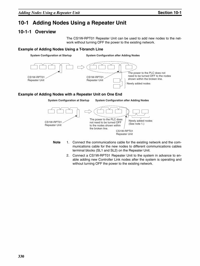
Adding Nodes Using a Repeater Unit Section 10-1
10-1 Adding Nodes Using a Repeater Unit
10-1-1 OverviewThe CS1W-RPT01 Repeater Unit can be used to add new nodes to the net-work without turning OFF the power to the existing network.
Example of Adding Nodes Using a T-branch Line
Example of Adding Nodes with a Repeater Unit on One End
Note 1. Connect the communications cable for the existing network and the com-munications cable for the new nodes to different communications cablesterminal blocks (SL1 and SL2) on the Repeater Unit.
2. Connect a CS1W-RPT01 Repeater Unit to the system in advance to en-able adding new Controller Link nodes after the system is operating andwithout turning OFF the power to the existing network.
System Configuration at Startup
CS1W-RPT01 Repeater Unit
CS1W-RPT01 Repeater Unit
System Configuration after Adding Nodes
The power to the PLC does not need to be turned OFF to the nodes shown within the broken line.
Newly added nodes
System Configuration at Startup System Configuration after Adding Nodes
CS1W-RPT01 Repeater Unit
CS1W-RPT01 Repeater Unit
The power to the PLC does not need to be turned OFF to the nodes shown within the broken line.
Newly added nodes (See note 1.)
330

Adding Nodes Using a Repeater Unit Section 10-1
10-1-2 Procedure for Adding Nodes
10-1-3 Precautions when Connecting Nodes Using a Repeater UnitWhen data links are active in the existing network, check the following itemsbefore adding nodes to the network. If the inappropriate data link tables orparameters are set, the system may not operate properly.
• If the new node will participate in user-set data links, make sure that theappropriate data link tables are set in the corresponding nodes.
• If the new node will not participate in user-set data links, make sure thatthe data link tables of the corresponding nodes are deleted.
Setting the Repeater Unit
Setting the additional nodes
Connecting and checking the cables
Check the operating conditions and setting status of the existing network.
Set the baud rate and terminating resistance switch on the Repeater Unit.
(1) Number of nodes registered in network and node addresses
(2) Baud rate setting(3) CS1W-RPT01 Repeater Unit connection(4) Data link mode when data links are
active/inactive(5) Wired Network 62 Node Enable Bit setting in
the DM Parameter Area(6) Ladder program (program that includes the
new nodes)
System Configuration before Adding Nodes
CS1W-RPT01 Repeater Unit
Prepare the nodes to be added.
Set the Control-ler Link settings for the new no-des.
Turn ON the power to the new nodes.
Set the DM Area parameters.
Turn OFF the power to the new nodes.
(1) Set the node address to a number that is not being used by another node on the network.
(2) Set the baud rate to match the settings for the existing network and Repeater Unit.
(3) Set the terminating resistance switch: Turn ON the terminating resistance for the nodes at both ends of the network (segment) only.
(1) Create I/O tables(2) Transfer user programs, etc.
Do not connect the communications cables yet.
(1) Set the polling/polled node setting to Polled.(2) Set the Wired Network 62 Node Enable Bit to match the setting for
the existing network. Check that the error indicators (ERC and ERH) are not lit. (When the node address is set to 33 or higher, the ERC indicator may turn ON. Turn ON the Wired Network 62 Node Enable Bit (to enable 62 nodes), turn ON the power again, and check that the ERC indicator is OFF.
System Configuration after Adding Nodes
CS1W-RPT01 Repeater Unit The cable to the new
node is not connected.
Connect the communications cables.
Turn ON the power to the Repeater Unit.
Turn ON the power to the new nodes.
Return the polling/polled node setting in the DM Area parameters to Polling.
Check that the PWR indicator is lit.
Join the new node to the existing network.The node is participating in the network normally if the INS indicator is lit and the ERC and ERH indications are not lit.
System Configuration after Adding Nodes
CS1W-RPT01 Repeater Unit The cable to the new
node is connected.
(1) Set the baud rate to match the settings for the existing network.(2) Set the terminating resistance switch: Turn ON the terminating resistance for
the Repeater Unit if it is at the end of the segment.
(Do not connect the communications cables yet.)
331

Adding Nodes Using a Repeater Unit Section 10-1
• If automatic settings are used, make sure that the appropriate DM Areaparameters have been set.
Check that the new data transmission that will be performed due to the newnodes has been considered in the user program for the existing networkbefore adding the nodes. If the ladder program is not suitable, the system maynot operate properly.
Make sure that the node addresses of the new nodes are not already beingused by other nodes in the same network. If the same node address is usedby more than one node, a node duplication error will be detected when thenode is added, communications will stop, and the node with the same addresswill not be able to the join the network. Data may also be unexpectedlyreceived from the incorrectly set node. To restore a Controller Link Unit with aduplicated address, reset the node address correctly, then turn ON the powerto the corresponding PLCs again, or restart the Controller Link Units.
Always set the baud rate of the new nodes and the Repeater Unit to the samebaud rate used for the existing network. If a different baud rate is set whenadding a new node, the communications for the whole network including theexisting network will be unstable and communications errors will occur.
Set the terminating resistance of the new nodes to the Repeater Unit asshown in the following diagram. If terminating resistance is set incorrectly,communications errors may occur.
• Adding Nodes Using T-branch Lines
• Adding Nodes with a Repeater Unit at One End
System Configuration after Adding Nodes
Terminating resistance ON
Terminating resistance ON
CS1W-RPT01 Repeater Unit
Terminating resistance ON
Newly added nodes
Terminating resistance ONTurn ON terminating resistance at the
nodes on both ends of each segment shown within broken lines.
Terminating resistance ON
Terminating resistance ON
Terminating resistance ON
CS1W-RPT01 Repeater Unit
Newly added nodes
Terminating resistance ON
Turn ON terminating resistance at the nodes on both ends of each segment shown within broken lines.
332

Adding Nodes Using a Repeater Unit Section 10-1
Before connecting the new nodes to the existing network, always set the poll-ing/polled node setting to Polled. If the nodes are connected to the existingnetwork with this setting set to Polling, the corresponding node may becomethe polling node for the network, which will affect the network in the followingways. After the new nodes are participating in the network normally, return thepolling/polled node setting to polling node.
• When the data link startup switch (software switch in the DM Area param-eters) of the new node is OFF, all the data links for the whole networkincluding the existing network will be inactive.
• When the network parameters being used are different from the defaultvalues, the network parameters will return to the default values.
Always set the Wired Network 62 Node Enable Bit in the DM Area parametersof the new node to match the settings of the existing network. If different set-tings are used, the network may not be configured correctly.
When a new node is to be added to a system that is already wired over a longdistance using T-branch lines or Repeater Units, turn OFF the power to thePLCs in the segment where the node is to be added. The power to the PLCsin segments separated by Repeater Units does not need to be turned OFF.The procedure for adding nodes is the same as 10-1-2 Procedure for AddingNodes.
Systems with an Existing T-branch Line
Systems Wired with an Existing Repeater Unit
CS1W-RPT01 Repeater Unit
The power to the PLCs of the segment shown within the dot-dash broken line does not need to be turned OFF.
The power to the PLCs in the segment shown within the dash broken line must be turned OFF.
New node to be added
New node to be added
The power to the PLCs of the segment shown in the dot-dash broken line does not need to be turned OFF.
The power to the PLCs in the segment shown in the dash broken line must be turned OFF.
CS1W-RPT01 Repeater Unit
333

Changing the Data Link Tables with Active Data Links Section 10-2
10-2 Changing the Data Link Tables with Active Data Links
10-2-1 OverviewThe data link tables can be changed and data link tables can be allocated fornewly added nodes while the system’s data links are active if the followingController Link Units and Support Boards are used.
Models that Support Data Link Table Changes during Active Data Links
Note 1. When using Controller Link Units and Support Boards that are not listed inthe above table, data link tables cannot be changed while data links are ac-tive.
2. CX-Programmer version 3.2 must be used to change data link tables withactive data links. CX-Programmer version 3.1 or lower versions cannot beused.
10-2-2 Example of Changing Data Link Table with Active Data Links
10-2-3 Operations when Changing Data Link TablesThe Controller Link Unit/Support Board that receives the command from theCX-Programmer version 3.2 or higher to change a data link table with activedata links will temporarily stop refreshing data with the PLC, change to thenew data link table (data link refresh allocation) and then resume refreshingdata links.
Nodes with data link tables that are changed will send the data from immedi-ately before the tables were changed while PLC data link refreshing isstopped.
Model Remarks
CS1W-CLK21-V1,CS1W-CLK23
Wired Controller Link Unit for CS-series PLCs
CJ1W-CLK21-V1,CJ1W-CLK23
Wired Controller Link Unit for CJ-series PLCs
3G8F7-CLK21-E-V1,3G8F7-CLK23-E
Wired Controller Link Support Board for PCI Bus
System Configuration at Startup System Configuration after Adding Nodes
CS1W-RPT01 Repeater Unit
CS1W-RPT01 Repeater Unit Newly added nodes
Data Link Area Data Link Area
Without stopping the data links, the data link tables can be changed to exchange data link data with the new nodes.
334

Changing the Data Link Tables with Active Data Links Section 10-2
Data link communications will continue, so the Communications Error Flag forthe data link status will not turn ON in any of the nodes in the network.
Refer to 10-2-4 Timing Required to Change Data Link Tables with Active DataLinks (Theoretical) for details on timing required to change the data linktables.
10-2-4 Timing Required to Change Data Link Tables with Active Data Links (Theoretical)
When changing data link tables with active data links, the data refresh for thecorresponding node will stop temporarily. During that time, even if the data inthe data link send area in the PLC is refreshed, it will not be sent as data linkdata to other nodes. Data received from other nodes will also not be shown inthe data link receive area of nodes with data link tables that are beingchanged. The data refresh interrupt timing (maximum theoretical value) is asfollows:
Data link refresh maximum interrupt time = 2 × Unit cycle time of the nodewith data link table being changed (See note 1.) + 3 × communications cycletime (ms)
Note 1. When CS- or CJ-series PLCs are being used, if the total number of datalink send words exceeds 7,800 words, this value is multiplied by 3.
2. Consider the effect of the data link refresh interrupt time on the applica-tions when changing the data link tables. If the maximum interrupt time isnot suitable for the user application, transfer the data link table after stop-ping the data links from a Programming Device as before, and then restartthe data links.
Command re-ceived to change with active data links
Change during active data links completed
Time
Data link send data
Data link receive data
Most recent data read from Unit
Data immediately before change
Most recent data read from Unit.
Most recent data received from other node
Data immediately before change
Most recent data received from other node
Refresh stopped Refresh resumed
Data link area of node with the data link table to be changed
335

Changing the Data Link Tables with Active Data Links Section 10-2
10-2-5 Procedure for Changing the Data Link Tables with CX-Programmer
The procedure for changing a data link table with active data links is shownhere using CX-Programmer version 3.2 and the following system configura-tion.
!Caution Check that the contents of the data link table to be changed are correct for thecorresponding node before changing them. If an incorrect data link table isset, the unexpected operation of the system may result in injury.
Note 1. Check that the contents of the data link table to be changed will be appro-priate for the corresponding node. If the data link table is set with inappro-priate data, the Unit may operate abnormally and cause injury.
2. Check that the effects of the data link table to be changed has been con-sidered in the user programs before changing a data link table.
3. CX-Programmer version 3.2 or higher must be used to change a data linktable with active data links. CX-Programmer version 3.1 or lower versionscannot be used.
Procedure
1,2,3... 1. Create the new data link table to be transferred to the node whose data linktable is to be changed (node 1) offline.
2. Save the created data link table in a file.
3. Connect the personal computer to CX-Net so that it is online.
4. Select Data Link − Setup from the Menu.
5. Open the data link table file saved in step 1.
Node 1 Node 2 Node 3 Node 4
CS1W-RPT01 Repeater Unit
Newly added node
Data Link Area
Node 1 Node 2 Node 3 Node 4
The table contents are as follows:Area 1: DM AreaFirst word: DM 00000Send and receive words: 10 words each
In this example, by adding node 4 to the network, the receive area from node 4 is added to the data link table of node 1.
336

Changing the Data Link Tables with Active Data Links Section 10-2
6. Use the mouse to select node 1, whose data link table is to be changed.
7. Select Online − Transfer to PLC while datalink active.
8. The following message box will be displayed. Click the Yes Button.If the Yes Button is clicked, the current data link table open in CX-Net willbe compared with the data link table of the node to be changed.If the No Button is clicked, the data link tables will not be compared.
After comparison, is there is any discrepancy, the following message boxwill be displayed. Click the OK Button to check the differences.
The differences between the data link table open on CX-Net and that of thenode to be changed will be displayed.
9. Check that the changes are correct, and click the OK Button.
337

Changing the Data Link Tables with Active Data Links Section 10-2
10. The Data Link Table Transfer Confirmation Message Box will be displayed.Click the Yes Button to transfer the data link table. The transfer can be can-celled by clicking the No Button. (The active data link table will not bechanged if the transfer is cancelled.)
11. When the data link table is written correctly, the following message box willbe displayed.
Note Transfer data link tables with active data links for one node at a time. Whenthe Online - Transfer to PLC while datalink active field is selected, the follow-ing message box will be displayed. Deselect the field and execute the com-mand again.
338

Changing the Data Link Tables with Active Data Links Section 10-2
339

Changing the Data Link Tables with Active Data Links Section 10-2
340

Appendix AStandard Models
Controller Link Units
Controller Link Support Board
Controller Link Support Software
Repeater Units
Applicable PLC Model number Remarks
CS-series PLCs CS1W-CLK21-V1CS1W-CLK23
The CS1W-CLK23 and CJ1W-CLK23 have expanded data link func-tionality (i.e., a maximum of 4,000 send words per node). They are upwardly compatible from the CS1W-CLK21-V1 and CJ1W-CLK21-V1, respec-tively.See CPU Units and Pro-gramming Devices in this appendix.
CJ-series PLCs CJ1W-CLK21-V1CJ1W-CLK23
CVM1 and CV-series PLCs CVM1-CLK21
C200HX/HG/HE PLC C200HW -CLK21
CQM1H-series PLCs CQM1H -CLK21
Applicable computer Model number Remarks
IBM PC/AT or compatible for PCI Bus
3G8F7-CLK21-EV13G8F7-CLK23-E
The 3G8F7-CLK23-E has expanded data link func-tionality (i.e., a maximum of 4,000 send words per node) and is upwardly compatible from the 3G8F7-CLK21-EV1.FinsGateway is included.
IBM PC/AT or compatible for ISA Bus
3G8F5-CLK21-E Controller Link Support Software included.
Applicable computer Model number Remarks
IBM PC/AT or compatible C200HW-ZW3AT2-EV2 For CS/CJ-series, C200HX/HG/HE, CVM1, and CV-series PLCs
Model Remarks
CS1W-RPT01 Wire-to-wire
CS1W-RPT02 Wire-to-optical (H-PCF cable)
CS1W-RPT03 Wire-to-optical (GI cable)
341

Standard Models Appendix A
Communications Cables (Twisted-pair Cables)
Relay Terminal Block
Personal Computer Network Configuration Tools
Note Windows 95 cannot be used when communicating through a Controller Link Support Board (PCI bus) orSYSMAC Link Support Board (PCI bus).
CPU Units and Programming Devices
CPU Units
Model Manufacturer Remarks
Li2Y-FCY2 x 0.56 qmm Kromberg & Schubert, Komtec Department
German company
1 x 2 x AWG – 20PE + Tr.CUSN + PVC
Draka Cables Industrial Spanish company
#9207 Belden USA company
ESVC 0.5 x 2 C-1362 Bando Densen Co. Japanese company
ESNC 0.5 x 2 C-99-087B Nihon Electric Wire & Cable Co.
Japanese company
ESPC 1P x 0.5 mm2 Nagaoka Electric Wire Co., Ltd.
Japanese company
Name Model number Remarks
Wired Controller Link Unit Relay Terminal Block
CJ1W-TB101 Cannot be used on the nodes on both ends of the network.
Applicable computer
Name Model number Applicable PLCs
IBM PC/AT or compatible run-ning Windows 98SE, Me, 2000, XP, or NT 4.0
CX-Integrator CXONE-AL@@C-EV2CXONE-AL@@D-EV2
CS/CJ-series
IBM PC/AT or compatible run-ning Windows 95 (See note.), 98, NT 4.0, 2000, or XP
CX-Program-mer with CX-Net
WS02-CXPC@-EV@ (version 2.1 or higher)
CS/CJ-series, C200HX/HG/HE, CVM1, CV-series, and CQM1H-series PLCs
PLC Model number Remarks
CS-series PLCs CS1H-CPU67-V1CS1H-CPU66-V1CS1H-CPU65-V1CS1H-CPU64-V1CS1H-CPU63-V1CS1G-CPU45-V1CS1G-CPU44-V1CS1G-CPU43-V1CS1G-CPU42-V1
Earlier versions of the CPU Units can also be used.
CJ-series PLCs CS1G-CPU45CS1G-CPU44
---
342

Standard Models Appendix A
Other Products Used with Controller Link Units
Refer to the operation manual for the relevant PLC for further information on the above products.
SYSMAC C200HX, C200HG, or C200HEor C200HZ PLCs
C200HE-CPU32/42-(Z)EC200HG-CPU33/43/53/63-(Z)EC200HX-CPU34/44/54/64-(Z)E
---
SYSMAC CV500, CV1000, or CV2000 PLCs (see note 1)
CV500-CPU01-EV1CV1000-CPU01-EV1CV2000-CPU01-EV1
Earlier versions of the CPU Units can also be used.
SYSMAC CVM1 PLCs (see note 1)
CVM1-CPU01-EV2CVM1-CPU11-EV2CVM1-CPU21-EV2CVM1D-CPU21-E
Earlier versions of the CPU Units can also be used.
SYSMACCQM1H-series PLCs
CQM1H-CPU51CQM1H-CPU61
---
PLC Model number Remarks
Lot No.: @ @ 4 6 ……… Manufactured in April 1996
Indicates the last digit of the manufacturing year. In this example, the year is 1996.
Indicates the month of manufacture. October, November, and December are indicated by x, y, and z respectively. In this example, the month is April.
Note Routing tables are required if any of the CVM1 or CV-series CPU Units in the network have been manufactured on or before April 1996. The manufacturing data can be determined from the lot number on the side of the CPU Unit.
Name Model number Remarks
Bus Connection Unit
C200HW-CE001 Required to connect a Controller Link Unit to a C200HZ, C200HX, C200HG, or C200HE CPU Unit.
C200HW-CE002 Required to connect two Controller Link Units, or one Controller Link Unit and one other Communications Unit to a C200HZ, C200HX, C200HG, or C200HE CPU Unit.
C200HW-CE012 Required to mount both a Controller Link Unit and a PLC Card Unit to a C200HZ, C200HX, C200HG, or C200HE CPU Unit.
Communications Boards
C200HW-COM01C200HW-COM04
Required to mount a Controller Link Unit to a C200HZ, C200HX, C200HG, or C200HE CPU Unit.
343

Standard Models Appendix A
344

Appendix BMemory Areas
This appendix provides easy reference to the words in PLC memory areas used by Controller Link Networks.
CS/CJ-series PLCs
Auxiliary Area
Network Status FlagsBits A20200 through A20207 are turned ON to indicate that ports #0 through #7, respectively, are enabled forthe SEND(90), RECV(98), CMND(490) and PMCR. Bits A219200 through A219207 are turned ON to indicatethat an error has occurred in ports #0 through #7, respectively, during data communications using SEND(90),RECV(98), CMND(490), or PMCR. Refer to page 192.
A203 through A210 contain the completion codes for ports #0 through #7, respectively, following data commu-nications using SEND(90), RECV(98), CMND(490), or PMCR. Refer to page 192.
CS/CJ CPU Bus Unit Initializing FlagsBits A30200 through A30215 turn ON while the corresponding CS/CJ CPU Bus Units (Units #0 through #15,respectively) are initializing.
CS/CJ CPU Bus Unit Setting Error Flag and Unit NumberBit A40203 is turned ON when the CS/CJ CPU Bus Units actually installed differ from the Units registered inthe I/O table. The unit number of the CS/CJ CPU Bus Unit involved is written to word A427.
Bits A42700 through A42715 correspond to CS/CJ CPU Bus Units #0 through #15, respectively. When a erroroccurs, the bit corresponding to the unit number of the CS/CJ CPU Bus Unit involved is turned ON.
CS/CJ CPU Bus Unit Error FlagBit A40207 is turned ON when a parity error occurs during the transmission of data between the CPU Unit andCS/CJ CPU Bus Units. The unit number of the CS/CJ CPU Bus Unit involved is written to word A417.
CS/CJ CPU Bus Unit NumbersBits A41000 through A41015 correspond to CS/CJ CPU Bus Units #0 through #15, respectively. When twoCPU Bus Units have the same unit number, the bits corresponding to the unit numbers of the CS/CJ CPU BusUnits involved are turned ON.
Word(s) Bit(s) Function
A202 00 to 07 Communications Port Enabled (Network Communi-cations Enabled) Flags
A203 to A210 00 to 15 Port #0 to #7 Completion Codes
A219 00 to 07 Port #0 to #7 Execute Error (Network Communica-tions Execute Error) Flags
A302 00 to 15 CS/CJ CPU Bus Unit Initializing Flags
A401 13 Duplicate Number Error Flag (fatal error)
A402 03 CS/CJ CPU Bus Unit Setting Error Flag
07 CS/CJ CPU Bus Unit Error Flag
A410 00 to 15 CPU Bus Unit Duplicate Number
A417 00 to 15 CS/CJ CPU Bus Unit Error, Unit Number Flags
A427 00 to 15 CS/CJ CPU Bus Unit Setting Error Unit Number
A501 00 to 15 CS/CJ CPU Bus Unit Restart Bits
345

Memory Areas Appendix B
CS/CJ CPU Bus Unit Duplication Error FlagBit A40113 is turned ON when two CS/CJ CPU Bus Units have been assigned the same unit number. The dupli-cated unit number is indicated in A410.
CS/CJ CPU Bus Unit Error, Unit Number FlagsWhen an error occurs in a data exchange between the CPU Unit and an CS/CJ CPU Bus Unit, the CS/CJ CPUBus Unit Error Flag (A40207) is turned ON and the bit in A417 corresponding to the unit number of the Unitwhere the error occurred is turned ON.
CS/CJ CPU Bus Unit Restart BitsBits A50100 through A50115 can be turned ON to reset CS/CJ CPU Bus Units number #0 through #15,respectively. The Restart Bits are turned OFF automatically when restarting is completed.
CIO Area: CS/CJ CPU Bus Unit AreaThe CS/CJ CPU Bus Unit Area (CIO Area) is allocated to CS/CJ CPU Bus Units according to the unit numbersassigned to them, as shown below. Each Unit is allocated 25 words.
Error Information: CIO 1500 + 25 × (Unit No.) (See page 302.)
Polling Node Address, Startup Node Address: CIO 1500 + 25 × (Unit No.) + 1 (See page 302.)
Unit no. Words Unit no. Words
0 1500 to 1524 8 1700 to 1724
1 1525 to 1549 9 1725 to 1749
2 1550 to 1574 10 1750 to 1774
3 1575 to 1599 11 1775 to 1799
4 1600 to 1624 12 1800 to 1824
5 1625 to 1649 13 1825 to 1849
6 1650 to 1674 14 1850 to 1874
7 1675 to 1699 15 1875 to 1899
1: Network parameter error (In PLC's EEPROM) 1: Data link table error (in PLC's EEPROM)1: Routing table error (in PLC's EEPROM)
1: PLC system setting error1: EEPROM error
1: Duplicate node address setting error1: Inconsistent network parameters
1: Communications controller send error1: Communications controller hardware error1: Error log exists
Polling node address Startup node address
Each node address is displayed in 2-digit BCD.
346

Memory Areas Appendix B
Network Participation Status: CIO 1500 + 25 × (Unit No.) + 2, + 3 (See pages 193, 302.)
Local Data Link Participation Status: CIO 1500 + 25 × (Unit No.) + 6 (See page 302.)
Data Link Status: CIO 1500 + 25 × (Unit No.) + 7 to + 22 (See pages 158, 303.)When the first data link status word for manually set data link tables or for automatically set data links is not setor is set to 0, the data link status is stored in the words shown below.
8-Bit Format Specified
The numbers in the squares indicate node addresses.The corresponding node participation status is as follows:0: Not part of the network1: Part of the network
+ 2+ 3
15 14 13 12 11 10 9 8 7 6 5 4 3 2 1 0
16 15 14 13 12 11 10 9 8 7 6 5 4 3 2 1
32 31 30 29 28 27 26 25 24 23 22 21 20 19 18 17
+ 4 48 47 46 45 44 43 42 41 40 39 38 37 36 35 34 33
+ 5 − − 62 61 60 59 58 57 56 55 54 53 52 51 50 49
1: Local node data link participating0: Local node data link not participating or data link
inactive
Allocation for automatic setting00: Equality layout01: 1:N allocation, common type10: 1:N allocation, 1 to 1 type11: 1:N allocation, chain type
Data link mode0: Manual setting1: Automatic setting
Node 2Node 4Node 6Node 8
Node 12Node 14Node 16Node 18
Node 22Node 24Node 26Node 28
PLC status0: Inactive (user program not running)1: Active (user program running)
Communications error (data link reception)0: Normal1: Error
PLC's CPU Unit error0: Normal1: Error
Data link participation0: Not in data link or data link inactive1: In data link
Offset error 0: Normal1: Error
Error: Offset exceeds number of send words.
Insufficient (short) receive area0: Sufficient1: Insufficient
Insufficient: Receive area is smaller than send area. Excess data is truncated; other data is received.
Remaining receive area0: Not remaining1: Remaining
Remaining: Receive area is larger than send area. Data is received and remaining words are cleared.
Node 1Node 3Node 5Node 7
Node 11Node 13Node 15Node 17
Node 21Node 23Node 25Node 27
+7+8
+21+22
Note When a data link with node addresses higher than 32 is required, specify the beginning storage word rather than us-ing the default.(In this case, a 31 word area is used when the 8-bit format is specified.)
+20+19+18
Node 10
Node 20
Node 9
Node 19
Node 30 Node 29Node 32 Node 31
+16+17
+15+14+13+12+11+10+9
347

Memory Areas Appendix B
4-Bit Format Specified
Terminating Resistance Status (CIO 1500 + 25 × (Unit No.) + 24 (See page 303.)
Node 4
PLC status0: Inactive (user program not running)1: Active (user program running)
Communications error (data link reception)0: Normal1: Error
PLC's CPU Unit error0: Normal1: Error
Data link participation0: Not in data link or data link inactive1: In data link
Node 8
Node 12
Node 16
Node 20
Node 24
Node 30
Node 32
Node 36
Node 40
Node 44
Node 48
Node 52
Node 58
Node 60
0
Node 3
Node 7
Node 11
Node 15
Node 19
Node 23
Node 27
Node 31
Node 35
Node 39
Node 43
Node 47
Node 51
Node 55
Node 59
0
Node 2
Node 6
Node 10
Node 14
Node 18
Node 22
Node 26
Node 30
Node 34
Node 38
Node 42
Node 46
Node 50
Node 54
Node 58
Node 62
Node 1
Node 5
Node 9
Node 13
Node 17
Node 21
Node 25
Node 29
Node 33
Node 37
Node 41
Node 45
Node 49
Node 53
Node 57
Node 61
Terminating resistance status: 0: OFF 1: ON
348

Memory Areas Appendix B
DM Area: CS/CJ CPU Bus Unit AreaThe CS/CJ CPU Bus Unit Area (DM Area) is allocated to CS/CJ CPU Bus Units according to the unit numbersassigned to them, as shown below. Each Unit is allocated 100 words, of which 10 words are used. In the Con-troller Link Unit this area is called the DM Area.
Software Switches (DM30000 + 100 × Unit No.) (See pages 147, 247, 253, 315.)
Unit no. Words Unit no. Words
0 DM30000 to DM30009
8 DM30800 to DM30809
1 DM30100 to DM30109
9 DM30900 to DM30909
2 DM30200 to DM30209
10 DM31000 to DM31009
3 DM30300 to DM30309
11 DM31100 to DM31109
4 DM30400 to DM30409
12 DM31200 to DM31209
5 DM30500 to DM30509
13 DM31300 to DM31309
6 DM30600 to DM30609
14 DM31400 to DM31409
7 DM30700 to DM30709
15 DM31500 to DM31509
Data link mode 000: Manual001: Automatic, equality layout
15 14 13 12 11 10 9 8 7 6 5 4 3 2 1 0
0 0 0 0 0 0 0
CS1 CPU Bus Unit PLC Setup Initialization (See note 1.)0: Do not initialize CS1 CPU Bus Unit PLC Setup 1: Initialize CS1 CPU Bus Unit PLC Setup
Polling node/polled node bit0: Polling node 1: Polled node
0
Data Link Start BitStart: Changed from OFF to ON or set to ON
when power is turned ON.Stop: Changed from ON to OFF.
0: Always set to 0.
Note 1: Initializes the network parameters registered in the CS1 CPU Bus Unit PLC Setup Area on the CPU Unit and clears the data link tables. 2: Be sure to set the bit in the DM Area's (CPU Bus Unit Area's) software switches (D30000 + 100 × unit
number) described as "always set to 0" to 0. Not doing so may result in the data link not starting properly.If a data link is started with bit 7 of the software switches set to 1, the data link status will be stored in aformat different to the one described in this manual (when using CS-series or CJ-series Controller Link Units).
Wired Network 62 Node Enable Bit0: 32 nodes max.1: 62 nodes max.
101: Automatic, 1:N allocation
Data link status storage format 0: 8-bit format 1: 4-bit format
349

Memory Areas Appendix B
Parameters for Automatically Setting Data Links with Equality Layout: D30000 + 100 × (Unit No.) + 1 to 9 (See page 147.)
Parameters for Automatic Data Link Creation with 1:N Allocation: D30000 + 100 × (Unit No.) + 12 to 25
Common Type
Words N+22 through N+25 register nodes that will participate in the data links. The numbers shown in the tableare the node addresses. The bit status for each node address indicates whether the node is to participate inthe data links.
Participate: ONNot participate: OFF
Area 1 data link start word (BCD)
Area 1 type
Number of send words per node of area 1 (BCD)
Rightmost 4 digits of data link start word of area 2 (DM area) (BCD)Leftmost digit of data link start word of area 2 (BCD)
First data link status word (BCD)
BCD: Set the value as binary-coded decimal.
Nodes to participate in the data links The numbers indicate node numbers.The value assigned indicates whether the node is to participate in the data links.Participate: 1Not participate: 0
15 8 7 0
15 14 13 12 11 10 9 8 7 6 5 4 3 2 1 0
16 15 14 13 12 11 10 9 8 7 6 5 4 3 2 1
+1
+2
+3
+4
+5
+6
+7
+8
32 31 30 29 28 27 26 25 24 23 22 21 20 19 18 17+9
Area 2 type
Number of send words per node of area 2 (BCD)
00
48 47 46 45 44 43 42 41 40 39 38 37 36 35 34 33+10
− − 62 61 60 59 58 57 56 55 54 53 52 51 50 49+11
15 8 7 0
N+12
N+13
N+14 00
N+15
N+16
N+17
N+18
N+19
N+20
N+21
N+22 16 15 14 13 12 11 10 9 8 7 6 5 4 3 2 1
N+23 32 31 30 29 28 27 26 25 24 23 22 21 20 19 18 17
N+24 48 47 46 45 44 43 42 41 40 39 38 37 36 35 34 33
N+25 --- --- 62 61 60 59 58 57 56 55 54 53 52 51 50 49
1:N allocation type (Set value 0001 = Common type)
Start word for area 1 (bit-access area, BCD)
Area for area 1
Area 1 send size (number of words) for master node (BCD)
Area 1 send size (number of words) for slave nodes (BCD)
Rightmost 4 digits of start word of area 2 (DM area) (BCD)
Area for area 2 Leftmost digit of start word of area 2 (BCD)
Area 2 send size (number of words) for master node (BCD)
Area 2 send size (number of words) for slave nodes (BCD)
First word to store data link status (bit-access area) (BCD)
350

Memory Areas Appendix B
1 to 1 Type
Words N+22 through N+25 register nodes that will participate in the data links. The numbers shown in the tableare the node addresses. The bit status for each node address indicates whether the node is to participate inthe data links.
Participate: ONNot participate: OFF
Chain Type
15 8 7 0
N+12
N+13
N+14
N+15
N+16
N+17
N+18
N+19
N+20
N+21
N+22 16 15 14 13 12 11 10 9 8 7 6 5 4 3 2 1
N+23 32 31 30 29 28 27 26 25 24 23 22 21 20 19 18 17
N+24 48 47 46 45 44 43 42 41 40 39 38 37 36 35 34 33
N+25 --- --- 62 61 60 59 58 57 56 55 54 53 52 51 50 49
1:N allocation type setting (Set value 0002 = 1 to 1 type)
Rightmost 4 digits of start word (BCD)
Area
Number of common send words for master node (BCD)
Number of individual send words for master node (BCD)
Number of send words for slave nodes (BCD)
0000 (Reserved)
0000 (Reserved)
0000 (Reserved)
First word to store data link status (bit-access area) (BCD)
Leftmost digit of area start word (BCD)
15 8 7 0
N+12
N+13
N+14
N+15
N+16
N+17
N+18
N+19
N+20
N+21
N+22 16 15 14 13 12 11 10 9 8 7 6 5 4 3 2 1
N+23 32 31 30 29 28 27 26 25 24 23 22 21 20 19 18 17
N+24 48 47 46 45 44 43 42 41 40 39 38 37 36 35 34 33
N+25 --- --- 62 61 60 59 58 57 56 55 54 53 52 51 50 49
1:N allocation type setting (Set value 0003 = Delivery type)
Rightmost 4 digits of area start word (BCD)
Area
Number of master common send words (BCD)
Number of receive and send words per node (BCD)
0000 (Reserved area)
0000 (Reserved area)
0000 (Reserved area)
0000 (Reserved area)
First word to store data link status (bit-access area) (BCD)
Leftmost digit of area start word (BCD)
351

Memory Areas Appendix B
Words N+22 through N+25 register nodes that will participate in the data links. The numbers shown in the tableare the node addresses. The bit status for each node address indicates whether the node is to participate inthe data links.
Participate: ONNot participate: OFF
C200HX/HG/HE PLCs
SR Area
Communications Instruction Response Codes: SR 237 (See page 194.)
Polling Node Address, Startup Node Address: SR 238, SR 242 (See page 297.)
Data Link Status: SR 239 to SR 241, SR 243 to SR 245 (See pages 158, 297.)When the first data link status word for manually set data link tables or for automatically set data links is not setor is set to 0, the data link status of only node addresses 1 to 6 will be given in the following area.
Operating level 0 response codeOperating level 1 response code
Each response code is in 2-digit hexadecimal.
SR 237
Operating level 0 SR 238
Operating level 1 SR 242
Polling node address Startup node addressEach node address is in 2-digit BCD.
Operating level 0 SR 239SR 240SR 241
Operating level 1 SR 243SR 244SR 245
PLC status 0: Inactive (user program not running)1: Active (user program running)
Communications error (data link reception)0: Normal1: Error
PLC's CPU Unit error 0: Normal1: Error
Data link participation0: Not in data link or data link inactive1: In data link
Offset error0: Normal1: Error
Error: Offset exceeds number of send words.
Insufficient (short) receive area 0: Sufficient1: Insufficient
Insufficient: Receive area is smaller than send area. Excess data is truncated; other data is received.
Remaining receive area0: Not remaining1: Remaining
Remaining: Receive area is larger than send area. Data is received and remaining words are cleared.
Node 2Node 4Node 6
Node 1Node 3Node 5
352

Memory Areas Appendix B
Operating Level Status: SR 252 (See pages 192, 298.)
AR AreaDuplicate Operating Levels/Refresh Error: AR 00 (See page 296.)
Routing Table Error/Unit Restart Bits: AR 01 (See page 296.)
Data Link Start Bits (See page 156.)
Network Participation Status: AR 08, AR 09, AR 12, AR 13 (See pages 193, 297.)
Operating level 1
Operating level 0
Network Instruction Enable Flag0: Disabled (operating)1: Enabled (not operating)Network Instruction Error Flag0: Normal completion1: Error
Network Instruction Enable Flag0: Disabled (operating)1: Enabled (not operating)Network Instruction Error Flag0: Normal completion1: Error
1: Local node data link participating
1: Local node data link participating
A bit will be turned ON (1) the next cycle when1) The same operating level is set more than once or2) A refresh error occurs between the Controller LInk Unit and the PLC's CPU Unit.
Operating level 1 Operating level 0
Operating level 1 Operating level 0
1: Routing table error
Resets the Controller Link Unit.Turn ON (1) and then OFF (0) to reset Unit.
Operating level 1 Operating level 0
Data link Start Bit for level 0 (AR 0700)Start: Changed from OFF to ON or set to ON when power is turned onStop: Changed from ON to OFF
Data link Start Bit of level 1 (AR 0704)Start: Changed from OFF to ON or set to ON when power is turned onStop: Changed from ON to OFF
15 14 13 12 11 10 9 8 7 6 5 4 3 2 1 0AR 07
Operating level 0 AR 08AR 09
Operating level 1 AR 12AR 13
The numbers in the squares indicate node addresses.The corresponding node participation status is as follows:0: Not part of network1: Part of network
353

Memory Areas Appendix B
Communications Controller Hardware Error, EEPROM Error: AR 11, AR 15 (See page 297.)
Service Time: AR 16, AR 17 (See page 297.)
Operating Level Connection Status, Inconsistent Network Parameters: AR 24 (See page 297.)
DM Parameter Area
Software Switches: DM 6400 and DM 6420 (See pages 147, 247, 253, 315.)
Parameters for Automatically Setting Data Links: DM 6400 to DM 6409, DM 6420 to DM 6429 (See page 147.)
Operating level 0 AR 11
Operating level 1 AR 15
1: Communications controller hardware error
1: EEPROM error
Operating level 0 AR 16
Operating level 1 AR 17
The service time for each PLC cycle is calculated by the PLC and displayed in 0.1-ms units in 4-digit BCD.
Operating level 1 Operating level 0 1: Network parameters do not match
1: Connecting to the operating levelOperating level 1 Operating level 0
Data link mode 00: Manual01: Automatic
15 14 13 12 11 10 9 8 7 6 5 4 3 2 1 0
0 0 0 0 0 0 0 0 0 0 0
EEPROM Clear Bit 0: Do not clear EEPROM 1: Clear EEPROM
Routing table enabled/disabled1: Enabled0: Disabled
Polling node/polled node bit0: Polling node 1: Polled node
Area 1 data link start word (BCD)
Area 1 type
Number of send words per node of area 1 (BCD)
Rightmost 4 digits of data link start word of area 2 (DM area) (BCD)Leftmost digit of data link start word of area 2 (BCD)
First data link status word (BCD)
BCD: Set the value as binary-coded decimal.
Nodes to participate in the data links The numbers indicate node numbers.The value assigned indicates whether the node is to participate in the data links.Participate: 1Not participate: 0
15 8 7 0
15 14 13 12 11 10 9 8 7 6 5 4 3 2 1 0
16 15 14 13 12 11 10 9 8 7 6 5 4 3 2 1
DM 6401 DM6421
DM 6402 DM6422
DM 6403 DM6423
DM 6404 DM6424
DM 6405 DM6425
DM 6406 DM6426
DM 6407 DM6427
DM 6408 DM6428
32 31 30 29 28 27 26 25 24 23 22 21 20 19 18 17DM 6409 DM 6429
Area 2 type
Number of send words per node of area 2 (BCD)
00
Level 0 Level 1
354

Memory Areas Appendix B
Routing Tables (DM 6450 to DM 6499) (See page 247.)When the use of routing tables is enabled by the software switch setting, the routing tables are stored in thesewords. Do not use them for anything else.
CVM1 and CV-series PLCs
Auxiliary Area
CPU Bus Unit Restart BitsBits A00100 through A00115 can be turned ON to reset CPU Bus Units number #0 through #15, respectively.The Restart Bits are turned OFF automatically when restarting is completed.
Do not turn these bits ON and OFF in the program; manipulate them from the CVSS.
CPU Bus Service Disable BitsBits A01500 through A01515 can be turned ON to stop service to CPU Bus Units numbered #0 through #15,respectively. Turn the appropriate bit OFF again to resume service to the CPU Bus Unit.
CPU Bus Unit Initializing FlagsBits A30200 through A30215 turn ON while the corresponding CPU Bus Units (Units #0 through #15, respec-tively) are initializing.
CPU Bus Error and Unit FlagsBit A40112 is turned ON when an error occurs during the transmission of data between the CPU Unit and CPUBus Units, or a WDT (watchdog timer) error occurs in a CPU Bus Unit. The unit number of the CPU Bus Unitinvolved is contained in word A405.
Bits A40500 through A40515 correspond to CPU Bus Units #0 through #15, respectively. When a CPU BusError occurs, the bit corresponding to the unit number of the CPU Bus Unit involved is turned ON.
CPU Bus Unit Setting Error Flag and Unit NumberBit A40203 is turned ON when the CPU Bus Units actually installed differ from the Units registered in the I/Otable. The unit number of the CPU Bus Unit involved is written to word A427.
Bits A42700 through A42715 correspond to CPU Bus Units #0 through #15, respectively. When a error occurs,the bit corresponding to the unit number of the CPU Bus Unit involved is turned ON.
CPU Bus Unit Error Flag and Unit NumbersBit A40207 is turned ON when a parity error occurs during the transmission of data between the CPU Unit andCPU Bus Units. The unit number of the CPU Bus Unit involved is written to word A422.
Bits A42200 through A42215 correspond to CPU Bus Units #0 through #15, respectively. When a CPU BusUnit Error occurs, the bit corresponding to the unit number of the CPU Bus Unit involved is turned ON.
Word(s) Bit(s) Function
A001 00 to 15 CPU Bus Unit Restart Bits
A015 00 to 15 CPU Bus Service Disable Bits
A302 00 to 15 CPU Bus Unit Initializing Flags
A401 12 CPU Bus Error Flag
A402 03 CPU Bus Unit Setting Error Flag
07 CPU Bus Unit Error Flag
A405 00 to 15 CPU Bus Unit Error Unit Number
A410 00 to 15 CPU Bus Unit Duplicate Number
A422 00 to 15 CPU Bus Unit Error Unit Number
A427 00 to 15 CPU Bus Unit Setting Error Unit Number
A502 00 to 07 Port #0 to #7 Enabled Flags
08 to 15 Port #0 to #7 Execute Error Flags
A503 to A510 00 to 15 Port #0 to #7 Completion Codes (See page 194)
355

Memory Areas Appendix B
CPU Bus Unit NumbersBits A41000 through A41015 correspond to CPU Bus Units #0 through #15, respectively. When two CPU BusUnits have the same unit number, the bits corresponding to the unit numbers of the CPU Bus Units involved areturned ON.
Network Status FlagsBits A50200 through A50207 are turned ON to indicate that ports #0 through #7, respectively, are enabled forthe SEND(192), RECV(193), and CMND(194). Bits A50208 through A50215 are turned ON to indicate that anerror has occurred in ports #0 through #7, respectively, during data communications using SEND(192),RECV(193), or CMND(194).
A503 through A510 contain the completion codes for ports #0 through #7, respectively, following data commu-nications using SEND(192), RECV(193), or CMND(194).
CIO Area: CPU Bus Unit AreaThe CPU Bus Unit Area is allocated to CPU Bus Units according to the unit numbers assigned to them, asshown below. Each Unit is allocated 25 words. The Controller Link Units use 22 of the words allocated to them.
Error Information: CIO 1500 + 25 × (Unit No.) (See page 302.)
Polling Node Address, Startup Node Address: CIO 1500 + 25 × (Unit No.) + 1 (See page 302.)
Network Participation Status: CIO 1500 + 25 × (Unit No.) + 2, + 3 (See pages 193, 302.)
Unit no. Words Unit no. Words
0 1500 to 1524 8 1700 to 1724
1 1525 to 1549 9 1725 to 1749
2 1550 to 1574 10 1750 to 1774
3 1575 to 1599 11 1775 to 1799
4 1600 to 1624 12 1800 to 1824
5 1625 to 1649 13 1825 to 1849
6 1650 to 1674 14 1850 to 1874
7 1675 to 1699 15 1875 to 1899
1: Network parameter error (In PLC's EEPROM) 1: Data link table error (in PLC's EEPROM)1: Routing table error (in PLC's EEPROM)1: PLC system setting error1: EEPROM error
1: Duplicate node address setting error
1: Inconsistent network parameters1: Communications controller send error1: Error log exists
Polling node address Startup node address
Each node address is displayed in 2-digit BCD.
The numbers in the squares indicate node addresses.The corresponding node participation status is as follows:0: Not part of the network1: Part of the network
+ 2+ 3
356

Memory Areas Appendix B
Local Data Link Participation Status: CIO 1500 + 25 × (Unit No.) + 6 (See page 302.)
Data Link Status: CIO 1500 + 25 × (Unit No.) + 7 to + 22 (See pages 158, 303.)When the first data link status word for manually set data link tables or for automatically set data links is not setor is set to 0, the data link status is stored in the words shown below.
1: Local node data link participating0: Local node data link not participating or data link inactive
Node 2Node 4Node 6Node 8Node 10Node 12Node 14Node 16Node 18Node 20Node 22Node 24Node 26Node 28Node 30Node 32
PLC status0: Inactive (user program not running)1: Active (user program running)
Communications error (data link reception)0: Normal1: Error
PLC's CPU Unit error0: Normal1: Error
Data link participation0: Not in data link or data link inactive1: In data link
Offset error 0: Normal1: Error
Error: Offset exceeds number of send words.
Insufficient (short) receive area0: Sufficient1: Insufficient
Insufficient: Receive area is smaller than send area. Excess data is truncated; other data is received.
Remaining receive area0: Not remaining1: Remaining
Remaining: Receive area is larger than send area. Data is received and remaining words are cleared.
Node 1Node 3Node 5Node 7Node 9Node 11Node 13Node 15Node 17Node 19Node 21Node 23Node 25Node 27Node 29Node 31
+7+8
+9
+10+11+12+13+14
+15
+16+17
+18+19+20+21
+22
357

Memory Areas Appendix B
DM Area: CPU Bus Unit AreaThe CPU Bus Unit Area (DM Area) is allocated to CPU Bus Units according to the unit numbers assigned tothem, as shown below. Each Unit is allocated 100 words, of which 10 words are used. In the Controller LinkUnit this area is called the DM Area.
Software Switches (DM2000 + 100 × Unit No.) (See pages 147, 247, 253, 315.)
Unit no. Words Unit no. Words
0 DM2000 to DM2009
8 DM2800 to DM2809
1 DM2100 to DM2109
9 DM2900 to DM2909
2 DM2200 to DM2209
10 DM3000 to DM3009
3 DM2300 to DM2309
11 DM3100 to DM3109
4 DM2400 to DM2409
12 DM3200 to DM3209
5 DM2500 to DM2509
13 DM3300 to DM3309
6 DM2600 to DM2609
14 DM3400 to DM3409
7 DM2700 to DM2709
15 DM3500 to DM3509
Data link mode Set to 01 for automatic setting.(00 is for manual setting. Other values are invalid.)
15 14 13 12 11 10 9 8 7 6 5 4 3 2 1 0
0 0 0 0 0 0 0 0 0 0 0
EEPROM Clear Bit* 0: Do not clear EEPROM 1: Clear EEPROM
Polling unit/polled unit bit0: Polling unit 1: Polled unit
0
Data link Start BitStart: Changed from OFF to ON or set to ON when power is turned onStop: Changed from ON to OFF
*Clears the network parameters, data link tables, and routing tables stored in EEPROM in the PLC's CPU Unit.
358

Memory Areas Appendix B
Parameters for Automatically Setting Data Links: DM 2000 + 100 × (Unit No.) + 1 to + 9 (See page 149.)
CQM1H-series PLCs
AR Area
Data Link Start Bit: AR 07 (See page 115.)
Number of send words per node of area 1 (BCD)
Rightmost 4 digits of data link start word of area 2 (BCD)Leftmost digit of data link start word of area 2 (BCD)
First data link status word (BCD)
15 8 7 0
15 14 13 12 11 10 9 8 7 6 5 4 3 2 1 0
16 15 14 13 12 11 10 9 8 7 6 5 4 3 2 1
+1
+2
+3
+4
+5
+6
+8
32 31 30 29 28 27 26 25 24 23 22 21 20 19 18 17+9
+7
Area 2 type
Number of send words per node of area 2 (BCD)
Area 1 data link start word (BCD)
Area 1 type
BCD: Set the value as binary-coded decimal.
Nodes to participate in the data links
The numbers indicate node numbers.The value assigned indicates whether the node is to participate in the data links.Participate: 1Not participate: 0
Word Bits Name Contents
AR 00 11 Communications Unit Error Flag Turns ON when an error occurs in a Communications Unit.
AR 01 11 Communications Unit Restart Bit Turn ON this bit to restart the Communications Unit.
AR 02 00 to 07 Response code Contains the completion code for network instructions (SEND(90), RECV(98), or CMND(––)).
(See page 194.)
08 Network Instruction Error Flag 0: Normal end to SEND(90), RECV(98), or CMND(––).1: Abnormal end (See page 193.)
09 Network Instruction Enable Flag 0: SEND(90), RECV(98), or CMND(––) execution not possi-ble (already executing)1: Execution possible (not executing)(See page 193.)
15 Communications Unit Connected Flag
Turns ON when a Communications Unit is mounted to the PLC.
AR 03 00 to 15 Communications Unit Servicing Time
Indicates the servicing time for the last cycle in 0.1-ms units (4-digit BCD.)
Data link Start Bit (AR0700)Start: Changed from OFF to ON or set to ON
when power is turned onStop: Changed from ON to OFF
15 14 13 12 11 10 9 8 7 6 5 4 3 2 1 0
359

Memory Areas Appendix B
Communications Unit Flags, Control Bits, and Status Information
Local Data Link Participation Status: IR 90 (See page 307.)
Data Link Status: IR 91 to IR 93 (See pages 158, 307.)When the first data link status word is not set or is set to the default (0000) for either the manually set data linktables or automatically set data link tables, the data link status is stored in the following words for nodes 1 to 6only.
Terminating Resistance Status: IR 95 (See page 310.)
1: Local node data link participating0: Local node data link not participating or data link
inactive
Node 2Node 4Node 6
PLC status0: Inactive (user program not running)1: Active (user program running)
Communications error (data link reception)0: Normal1: Error
PLC's CPU Unit error0: Normal1: Error
Data link participation0: Not in data link or data link inactive1: In data link
Offset error 0: Normal1: Error
Error: Offset exceeds number of send words.
Insufficient (short) receive area0: Sufficient1: Insufficient
Insufficient: Receive area is smaller than send area. Excess data is truncated; other data is received.
Remaining receive area0: Not remaining1: Remaining
Remaining: Receive area is larger than send area. Data is received and remaining words are cleared.
Node 1Node 3Node 5
IR 91IR 92
IR 93
Terminating resistance status: 0: OFF 1: ON
360

Memory Areas Appendix B
Controller Link Status Information
Error Information: IR 190 (See page 306.)
Polling Node Address, Startup Node Address: IR 191 (See page 306.)
Network Participation Status: IR 192 and IR 193 (See page 306.)
PLC Setup Settings in DM Area
Control Bits: DM 6400 (See pages 115, 247, 253, 323.)
1: Data link table error (in Controller Link's EEPROM)
1: Routing table error (in Controller Link's EEPROM)
1: EEPROM error
1: Duplicate node address setting error1: Inconsistent network parameters1: Communications controller send error
1: Communications controller hardware error1: Error log exists
1: Network parameter error (In Controller Link's EEPROM)
Polling node address Startup node address
Each node address is displayed in 2-digit BCD.
The numbers in the squares indicate node addresses.The corresponding node participation status is as follows:0: Not part of the network1: Part of the network
EEPROM Clear Bit0: Do not clear EEPROM 1: Clear EEPROM
Polled node/polling node0: Polling node 1: Polled node
Routing Table Enable Bit1: Enabled0: Disabled
Data link mode 00: Manual setting01: Automatic setting
361

Memory Areas Appendix B
Automatic Data Link Parameters: DM 6401 to DM 6409 (See page 152.)
Routing Tables: DM 6450 to DM 6499 (See page 243.)These words are used for the routing tables if the data links are enabled in the software switches. Do not usethese words for any other purpose if data links are enabled.
Number of send words per node of area 1 (BCD)
Rightmost 4 digits of data link start word of area 2 (BCD)Leftmost digit of data link start word
First data link status word (BCD)
15 14 13 12 11 10 9 8 7 6 5 4 3 2 1 0
16 15 14 13 12 11 10 9 8 7 6 5 4 3 2 1
of area 2 (BCD)
DM 6401
DM 6402
DM 6403
DM 6404
DM 6405
DM 6406
DM 6408
32 31 30 29 28 27 26 25 24 23 22 21 20 19 18 17DM 6409
DM 6407
00
Area 2 type
Number of send words per node of area 2 (BCD)
Area 1 data link start word (BCD)
Area 1 type
BCD: Set the value as binary-coded decimal.
Nodes to participate in the data links
The numbers indicate node numbers.The value assigned indicates whether the node is to participate in the data links.Participate: 1Not participate: 0
362

Appendix CUsing the Relay Terminal Block
This appendix describes how to use the CJ1W-TB101 Wired Controller Link Unit Relay Terminal Block. Using aRelay Terminal Block enables replacing a Controller Link Unit while network communications are still in
progress.
Relay Terminal Blocks (CJ1W-TB101) can be used on any node but the end nodes to enable replacing theController Link Unit with the communications cable connected and turn OFF the power to only the Unit beingreplaced.
Note The built-in terminating resistance connected at the Units at the end of the network prevents using theRelay Terminal Block on the end Units.
Connecting the Relay Terminal Block to the Communications Terminal Block on the Controller Link Unit1. Connect the communications cables from the two adjacent nodes together to the terminals on the Relay
Terminal Block. The tightening torque for the Relay Terminal Block terminal screws is 0.5 N·m.
2. Remove the terminal block cover from the communications terminal block on the Controller Link Unit andloosen the three screws on the communications terminal block. (If adjacent Units are close enough to inter-fere with work, remove the three screws.)
3. Confirming that the signal lines and shield lines are aligned properly with the markings on the Controller LinkUnit, insert the Relay Terminal Block and tighten the screws on the communications terminal block to securethe Relay Terminal Block. The tightening torque for the three communications terminal block terminal screwsis 0.5 N·m.
Appearance Name Model number Remarks
Wired Controller Link Unit Relay Terminal Block
CJ1W-TB101 Cannot be used on the nodes on both ends of the network.
363

Using the Relay Terminal Block Appendix C
4. Attach the terminal block cover to the communications terminal block on the Controller Link Unit.
Replacing a Controller Link Unit with a Relay Terminal BlockUse the following procedure to replace a Controller Link Unit with a Relay Terminal Block. The communicationscables are left connected to the Relay Terminal Block during the procedure, and only the Relay Terminal Blockitself must be disconnected from the Controller Link Unit and then connected to the new Controller Link Unit.
The following procedure describes only steps required for the Relay Terminal Block. Refer to 9-6-1 Replacingthe Unit for details on the replacement operation.
1. Turn OFF the power supply to the PLC with the Unit to be replaced.
2. Remove the communications terminal block cover from the Unit.
3. Loosen the three screws on the communications terminal block. (If adjacent Units are close enough to in-terfere with work, remove the three screws.)
4. Remove the Relay Terminal Block with the communications cables still attached to it.
!Caution Do not allow the metal portions of the Relay Terminal Block or the communications cable crimpterminals to come into contact with any conductive material.
5. Replace the Controller Link Unit. Set the node number, baud rate, operating level, and terminating resis-tance switches on the new Unit to the same settings as the previous Unit. With the C200HX/HG/HE orCQM1H PLC, turn ON the power to the PLC, download the data that was backed up from the previous Unitto EEPROM in the new Unit, and then turn OFF the power again.
6. Remove the communications terminal block cover from the new Unit.
7. Loosen the three screws on the communications terminal block on the new Unit. (If adjacent Units are closeenough to interfere with work, remove the three screws.)
8. Attach the Relay Terminal Block to the new Unit with the communications cables still attached to it, makingsure to align the signal lines and shield line with the markings on the Controller Link Unit.
9. Tighten the screws on the communications terminal block to secure the Relay Terminal Block. The tighten-ing torque for the three communications terminal block terminal screws is 0.5 N·m.
10. Attach the terminal block cover to the communications terminal block on the Controller Link Unit.
11. Turn ON the power supply to the new Unit. (The power supply to other nodes should still be ON.)
BAUD RATE
12
ON
SW1
ONTER SW
ON
12
Relay Terminal Block
Connect the Relay Terminal Block.
BAUD RATE
12
ON
SW1
ONTER SW
BD H
BD L
SHLD
ON
12
Relay Terminal Block Connect the Relay Terminal Block.
364

Using the Relay Terminal Block Appendix C
Note 1. Signal will still be flowing through the communications cables during the replacement procedure if thenetwork is still operating. Use an insulated screwdriver and be very sure that the metal portions of theRelay Terminal Block or the communications cable crimp terminals do not come into contact with anyconductive material.
2. Replace the Unit only after confirming that doing so will not affect the system, including the affects ofseparated nodes or communications errors.
3. Always turn OFF the power supply to all nodes when connecting communications cables to or remov-ing them from the Relay Terminal Unit.
365

Using the Relay Terminal Block Appendix C
366

Index
Numerics1 to 1 type, 10, 132, 1411:N allocations
1 to 1 type, 10, 132, 141chain type, 10, 132, 143common type, 10, 132, 137
4-bit format, 158, 160, 162, 293, 3488-bit format, 158, 159, 162, 292, 347
A-Bapplications precautions, xxiv, 29AR Area
reading, 217, 219writing, 218
asynchronous operation, 262automatic setting
1:N allocations, 10, 132, 133setting example, 153
bitscontrolling, 225, 226
Bus Connection Unitsmodels, 343
CC200HX/HG/HE PLCs
installation, 61memory areas, 352models, 343RECV, 172RECV delay time, 270SEND, 171SEND delay time, 268SEND/RECV instructions, 171synchronous operation, 260
cables, 8communications cables, 68
connecting, 70optical, 76
chain type, 10, 132, 143CJ-series PLCs
data link tables, 117installation, 64memory areas, 345models, 342
clockreading, 224setting, 224
CMND instructionmessage service, 168
commandsFINS commands, 202
commands for C200HX/HG/HE and CQM1H-series PLCs,215
CLOCK READ, 224CLOCK WRITE, 224
CONTROLLER DATA READ, 222CONTROLLER STATUS READ, 223ERROR CLEAR, 225FORCED SET/RESET, 225FORCED SET/RESET CANCEL, 226MEMORY AREA READ, 217MEMORY AREA WRITE, 218MULTIPLE FORCED STATUS READ, 227MULTIPLE MEMORY AREA READ, 219PROGRAM AREA READ, 219PROGRAM AREA WRITE, 220
commands for Controller Link Units, 204BROADCAST TEST DATA SEND, 213BROADCAST TEST RESULTS READ, 212CONTROLLER DATA READ, 205CONTROLLER STATUS READ, 206DATA LINK START, 204DATA LINK STATUS READ, 210DATA LINK STOP, 204ECHOBACK TEST, 212ERROR LOG CLEAR, 214ERROR LOG READ, 213NETWORK STATUS READ, 208
commands for CS/CJ-series PLCs, 186commands for CVM1 and CV-series PLCs, 186common type, 10, 132, 137communications
cables, 21, 76models, 342, 363optical, 76
data exchange timing, 257data processing time, 258instructions, 189mechanism, 252preparations, 34selecting functions, 27timing calculation example, 259
Communications Boardsmodels, 343
Communications Cables, 21, 76models, 342, 363
communications cycle time, 255active data links, 255definition, 252non-active data links, 256
Controller, 53Controller Link, 2
networkconnections, 68features, 8reading operating status, 208remote, 241
Controller Link Support Boardsmodels, 341
Controller Link Support Software, 24, 26models, 341stopping and starting data links, 157
Controller Link UnitsC200HX/HG/HE, 51
367

Index
settings, 95CJ Series
settings, 91CJ-series PLCs, 48CQM1H Series
settings, 102CQM1H-series PLCs, 55CS Series
settings, 88CS-series PLCs, 46CVM1 and CV Series
settings, 99CVM1 and CV-series PLCs, 53models, 18, 341
counterschanging PV, 218reading Completion Flag status, 217, 219reading PV, 219
CPU Unitsmodels, 342
CQM1H-series PLCsCMND, 182installation, 66instructions, 178memory areas, 359models, 343RECV, 179SEND, 178synchronous operation, 260
CS-series PLCsdata link tables, 117installation, 63memory areas, 345models, 342
CVM1 and CV-series PLCsasynchronous operation, 262CMND, 182, 183commands, 186installation, 62memory areas, 355RECV, 177RECV delay time, 266SEND, 176SEND delay time, 264SEND/RECV instructions, 176synchronous operation, 260
CVM1 PLCsmodels, 343
CV-series PLCsmodels, 343See also CVM1 and CV-series PLCs
CX-Net, 26, 115CX-Programmer, 26, 241, 242
Ddata areas
See also Memory Areasdata link table
C200HX/HG/HE PLCs, 119changing during operation, 11, 334CQM1H-series PLCs, 122creating manually, 125CVM1 and CV-series PLCs, 121specifications, 117
data links, 81 to 1 type, 140automatic setting, 36, 131
1:N, 10, 131, 133examples, 110
chain type, 143, 144common type, 136creating, 28description, 108equality layout, 134error detection, 164I/O response time, 257manual setting, 34, 116
examples, 109, 125from computer node, 117from Programming Device, 116
modes, 162procedures, 34reading data link status, 210selecting automatic or manual, 115setting, 115specifications, 113starting, 155, 204status, 158
manipulating bit/word status, 163storage format, 158, 162, 280, 292, 293, 347, 349
specifying, 159using data link status area, 158using indicators, 158
stopping, 155, 204stopping and starting, 156
dimensionsC200HX/HG/HE Units, 52CJ-series Units, 50CQM1H Units, 56CS-series Units, 48CVM1 and CV Units, 55
DM Areareading, 217, 219writing, 218
E-FEC Directives, xxviEMC Directives, xxvierror codes, 311error log, 7, 310
reading and clearing, 317table, 310
error messages, 224errors
clearing, 214, 225error handling, 9
368

Index
error log, 7reading, 213response codes, 230
FAL/FALS No., 224fatal error data, 223FINS commands
errors, 230response codes
errors, 230sending and receiving, 202
responses, 202sending and receiving, 202stopping and starting data links, 157
flagsNetwork Instruction Enabled Flag, 192, 193Network Instruction Error Flag, 192, 193SEND/RECV, 192SEND/RECV operations, 194status
troubleshooting, 299forced status
canceling, 226controlling, 225reading, 227
II/O tables, 34, 37indicators
checking data link status, 158Controller Link Units
C200HX/HG/HE Units, 51CJ-series Units, 49CQM1H Units, 55, 57, 58, 60CS-series Units, 47CVM1 and CV-series Units, 53
troubleshooting using indicators, 274inspection
tools and equipment needed, 321installation, 34, 60
C200HX/HG/HE PLCs, 61CJ-series PLCs, 64communications cables, 68, 70CQM1H-series PLCs, 66CS-series PLCs, 63CVM1 and CV-series PLCs, 62SYSMAC LINK Unit, 62
instructionsCMND, 182RECV, 169SEND, 169
IR Areareading, 217, 219
L-MLow Voltage Directive, xxvimaintenance
cleaning, 321
inspection, 321manual setting
examples, 125memory areas, 345
designating addresses, 215reading, 217reading contents of memory area words, 219writing, 218
message delay times, 264message service, 8, 29
operations, 190procedure, 42specifications, 191
model numbersreading PLC model number, 222
models, 18
Nnetwork
interconnecting Controller Link networks, 238interconnecting other OMRON networks, 238other remote networks, 242parameters, 254
specifying, 255relay errors, 229remote Controller Link networks, 241
node addressessetting
C200HX/HG/HE Units, 96CJ-series Wired Units, 93CQM1H Units, 103CS-series Wired Units, 89CVM1 and CV Units, 100
node configurations, 9nodes
extending to 62Enable Bit, 81, 349
nodes, extending to 62, 10, 81non-fatal error data, 223number of polled units, 254
O-Poffsets
application example, 112usage, 112
operating environment precautions, xxiiiOptical Fiber Cables
accessories, 77optical fiber cables
See also cablesoverview, 2PLC
modes, 223changing to PROGRAM mode, 221changing to RUN mode, 221
PLC memory addres. See also Memory Areas
369

Index
reading, 222reading controller status, 206, 223receiving routing table settings, 247status, 222
polling cycledefinition, 252
polling nodesetting, 253
precautionsapplications, xxiv, 29general, xxiihandling, 321operating environment, xxiiireplacing the Unit, 322safety, xxii
proceduresmessage service, 29
programmingPLC programming examples, 197remote, 240
Programming Devices, 23, 241models, 343
programsreading, 219writing, 220
RRAS functions, 7RECV, 170RECV delay time, 266RECV instruction, 169
C200HX/HG/HE PLCs, 270CS/CJ-series PLCs, 266CVM1 and CV-series PLCs, 266message service, 168
Repeater Units, 9, 12, 66, 73, 80, 104, 332response codes, 194, 228, 230
C200HX/HG/HE PLCs, 195C200HXH/HG/HE and CQM1H-series PLCs, 195CQM1H-series PLCs, 195CS/CJ-series, CVM1, and CV-series PLCs, 195
routing tables, 243creating, 243editing, 245saving, 246setting, 244
examples, 248procedure, 245
transferring, 247
Ssafety precautions, xxiiSEND, 169SEND delay time, 264SEND instruction, 169
C200HX/HG/HE PLCs, 268
CS/CJ-series PLCs, 264CVM1 and CV-series PLCs, 264message service, 168
SEND/RECV instructions, 169settings
baud ratesC200HX/HG/HE Units, 97CJ-series Wired Units, 94CQM1H Units, 103CS-series Wired Units, 90CVM1 and CV Units, 101
node addressesC200HX/HG/HE Units, 96CJ-series Wired Units, 93CQM1H Units, 103CS-series Wired Units, 89CVM1 and CV Units, 100
operating levelsC200HX/HG/HE Units, 97CJ-series Wired Units, 94CS-series Wired Units, 90
polling nodes, 253settings after replacing Unit, 323terminating resistance
C200HX/HG/HE Units, 98CJ-series Wired Units, 94CQM1H Units, 104CS-series Wired Units, 91CVM1 and CV Units, 101
unit numbersCJ-series Wired Units, 92CS-series Wired Units, 88CVM1 and CV Units, 100
specificationscommunications, 15data link, 113general, 14message service, 191
standard models, 341startup procedures, 27status area, 7
troubleshooting, 290stopping and starting
data linksusing Controller Link Support Software, 157using FINS commands, 157
synchronous operation, 260system configuration, 12
Tterminating resistance
settingC200HX/HG/HE Units, 98CJ-series Wired Units, 94CQM1H Units, 104CS-series Wired Units, 91CVM1 and CV Units, 101
370

Index
timerschanging PV, 218reading Completion Flag status, 217, 219reading PV, 219
troubleshooting, 274status area, 290status flags, 299using indicators, 274
U-Wunit numbers
settingCJ-series Wired Units, 92CS-series Wired Units, 88CVM1 and CV Units, 100
Wired Network 62 Node Enable Bit, 81, 349wiring
Wired Controller Link Units, 68
371

Index
372

Revision History
A manual revision code appears as a suffix to the catalog number on the front cover of the manual.
The following table outlines the changes made to the manual during each revision. Page numbers refer to theprevious version.
Revision code
Date Revised content
1 February 1997 Original production
2 August 1997 Removed “-HZ” model suffix throughout the manual.Page 76: “CMND” corrected to “SEND” in the diagram for the “PC to computer” message service in the table.Page 88: “C” bit added to the program example.Page 145: Second sentence removed and the equations corrected for 8-3-2 Data Pro-cessing Time.
3 February 1999 CS1W-CLK11 and CS1W-CLK21 Controller Link Units for CS/CJ-series PCs added.“Common memory” corrected to “shared memory” throughout the manual.Addition of new 3G8F5-CLK11-E optical model and optical system information throughout the manual.
4 September 1999 CQM1H-CLK21 Controller Link Units for CQM1H-series PCs added.
5 May 2001 CJ1W-CLK21 Controller Link Units for CJ-series PCs added (including changing “CS1” to “CS” or CS/CJ” according to context).An appendix was added on the Relay Terminal Block.Information on optical systems removed.Page xiii: “Connector” changed to “any terminal block.”Page xiv: “Connector” removed, “communications connector” changed to “Bus Connec-tion Unit,” and “backup power supply cable” removed.Page xv: “CS1W-CLK11” removed.Page 3: Graphic altered.Page 5: Information added on personal computer boards.Page 6: Information on H-PCF and GI cables added.Pages 6 and 17: Note changed/added.Pages 10 and 16: Information added/changed in table.Pages 11 and 12: Information added on wiring.Page 15: Note and information following it removed and other changes.Page 17: Note added in graphic.Page 19: Parenthetic information changed in procedure.Page 30: Unit number callout corrected.Page 45: Recommended wire added.Page 54: Corrected “bottom switch” to “front switch.”Page 76: Notes changed.Page 146: Corrected version information.Page 159: Restriction added on number of read words.Page 250: First paragraph in 9-3 Error Log corrected.
Cat. No. W309-E1-11
Revision code
373

Revision History
06 February 2003 “PC” changed to “PLC” throughout the manual. Information related to the CQM1H-CLK21 was added and information related to the CS1W-CLK21 was removed. In addition, the fol-lowing changes were made.Page v: Changes made to information on product references.Pages 17, 73, 104, 272: Information on software switches added.Pages 52, 55: Changes made to table giving baud rates.Pages 79, 80: “-EV@” added to model numbers in several of places.Page 100: Parenthetic information added to first paragraph.Page 107: Programming examples added.Pages 137, 141: Numerical change: 120000 changed to 121000.Pages 214, 216: “Scan” changed to “cycle” in several places.Page 250: Minor change made to first paragraph.
07 June 2003 Numerous changes were made to add the new functions and features of CS1W-CLK21-V1 and CJ1W-CLK21-V1 Units and the CS1W-PRT01/02/03 Repeater Units.
08 September 2004 Extensive changes were made to the manual mainly to add information on the upgraded functionality of new unit versions, including an overview of the new system of unit version codes.
09 January 2006 “CS1-series” changed to “CS-series” throughout the manual.Page v: Information on general precautions notation added andcopyright information moved from page vii.Page xv: Information on liability and warranty added.Pages 115, 117, 119, and 120: “PC” changed to “PLC.”
Revision code
Date Revised content
374

Revision History
10 September 2007 Added the CS1W-CLK13, CS1W-CLK23, CJ1W-CLK23, CS1W-CLK53, 3G8F7-CLK13-E, 3G8F7-CLK23-E, and 3G8F7-CLK53-E throughout the manual. Page vii: Added note and information on CX-Integrator.Pages 7, 168, 180: Added note. Page 7: Changed the maximum number of errors to 64. Page 8: Changed information in table and paragraph before Message Service.Page 11: Changed CX-Programmer to CX-Integrator and added section. Page 14: Changed specifications for number of data link words and changed notes. Page 18: Updated table and notesPage 19: Changed note in table. Page 21: Changed notes after table. Page 25: Removed notes after table. Page 29: Added precautions. Pages 44, 46: Changed heading. Page 62: Removed first sentence from first paragraph after note and changed example. Page 63: Changed first paragraph on page and removed first sentence from first paragraph after note.Page 64: Changed example, including table. Page 106: Updated table and note after table. Page 108: Updated note. Page 109: Updated note 4. Page 111: Changed description of number of data link words. Page 116: Changed setting range descriptions for number of words. Page 129: Changed second bullet after last note. Page 202: Changed information under Model. Page 203: Added bit description to top figure. Page 204: Added information at bottom of page. Page 210: Changed descriptions of beginning record number, number of records, and number of stored records, and added table. Page 228: Added information to second row of probable cause of error code 02 05.Page 229: Added information to remedy of error code 05 04.Pages 256 to 263: Updated section. Page 278: Changed probable remedy in third row of table. Page 281: Changed last paragraph of cause and remedy in fourth row of table. Page 296: Changed probable remedy in second row of table. Page 297: Changed probable remedy in first, third, and fifth rows of table and probable cause in fifth, sixth, and eighth rows. Page 298: Changed probable remedy in fourth row of table. Page 306: Changed probable remedy in second row of table. Page 307: Changed probable remedy in fifth row of table and probable cause in third, fifth, and sixth rows. Pages 308 and 310: Changed probable remedy in fourth row of table.Page 311: Changed probable remedy in first and second rows of bottom table.Page 312: Changed probable remedy in sixth row of table.Page 313: Changed second paragraph, specification for number of records, and information after table. Pages 318 and 319: Added references to note 4 (six times) and added note 4. Page 322: Added row for Node XX Node size.Page 324: Changed text after bottom table. Page 343: Added remarks to Control Link Unit table and added one row to Controller Link Support Board table. Page 344: Changed top table.
11 May 2008 Pages 21, 22, and 342: Added row to top table.Pages 57, 59, and 60: Changed the dimension with the connector and added note.Pages 68 and 74: Added row to table.Page 71: Changed information on crimp terminals for step 7.
Revision code
Date Revised content
375

Revision History
376