controllable synthesis and magnetism of iron oxides nanorings
TRANSCRIPT

RE
SE
AR
CH
AR
TIC
LE
Copyright © 2010 American Scientific PublishersAll rights reservedPrinted in the United States of America
Journal ofNanoscience and Nanotechnology
Vol. 10, 1–12, 2010
Controllable Synthesis and Magnetism ofIron Oxides Nanorings
Baoliang Lv1�2, Yao Xu1�∗, Qiang Gao1�2, Dong Wu1, and Yuhan Sun11State Key Laboratory of Coal Conversion, Institute of Coal Chemistry, Chinese Academy of Sciences,
Taiyuan 030001, China2Graduate University of the Chinese Academy of Sciences, Beijing 100049, China
Hematite (�-Fe2O3� nanorings were prepared via a facile hydrothermal route without using anytemplate. The products were characterized by X-ray powder diffraction (XRD), X-ray photoelectronspectroscopy (XPS), scanning electron microscopy (SEM), and transmission electron microscopy(TEM). On the basis of these characterizations and condition experiments, an “oriented dissolu-tion and recrystallization” mechanism under the effect of H2PO
−4 ions was proposed to explain the
formation process of nanoring structure. Magnetite (Fe3O4� nanorings were obtained by reducing�-Fe2O3 nanorings, and then maghemite (�-Fe2O3� nanorings were obtained by reoxidizing Fe3O4
nanorings. The magnetic properties of these nanorings were investigated, and it was found thatthese nanorings have higher coercivity and lower saturation magnetization than many other nano-structures of iron oxides. The adsorbed phosphate on the surface and the nanoring morphologymight be responsible for this phenomenon. Furthermore, it is interesting to find that the coercivity ofthe nanorings increased with the increase of din/dout (din and dout are the inner and outer diametersof the rings, respectively), and a rapid increase was observed at the value of din/dout around 0.5.
Keywords: Iron Oxide, Nanorings, Magnetic Property, Coercivity.
1. INTRODUCTION
The interest in nanoscale materials stems from the factthat new properties are acquired at this length scale and,equally important, that these properties change with theirsize or shape.1 Recent years, materials with nanoring struc-ture have attracted intense research interest because oftheir novel properties and promising applications. Sev-eral groups have fabricated nanoring structures of ZnO,2–4
CdS,5 Au,6 Cd(OH) 72 and Gd2O3.8 And some progresses
have been made in the application of nanorings. For exam-ple, magnetic nanorings could maintain stable vortex statesand hence hold the potential for information storage intwo chiralities of the circulating magnetization, whichmade them promising candidates for high-density mag-netic random access memory (HDRAM).9�10 Gold nanor-ings showed the enhanced localized electromagnetic fieldsin their ring cavities.11 Also, persistent currents in metalrings and superconducting rings have been studied.12�13
Magnetic material is of great importance in variousmaterials. In order to improve the magnetic property forspecific technological application, magnetic materials with
∗Author to whom correspondence should be addressed.
different geometrical shapes and patterns have been fab-ricated and simulated.14–16 One of the most successfulnanomagnets, individual or in arrays, has been the ringshape nanomagnet due to the fact that nanorings havebeen proposed as bricks to fabricate magnetic randomaccess memories in a vertical configuration with negligi-ble magnetostatic interaction.17�18 Several interesting mag-netic states have been discovered in these nanorings. Forexample, the magnetostatic fields of magnetic rings can beentrained into chiral domains commonly referred to as flux-closure (FC) states, and the magnetic dipoles are alignedinto a closed circuit and produce a net moment of zero,which minimizes both the magnetic energy and the fieldoutside of the ring.19–22 As a class of important magneticmaterials, iron oxides with nanoring structure may haveinteresting magnetic properties. Furthermore, iron oxidesparticles combine such functionality with low cost and lowtoxicity.23–25 In the last decades, many iron oxides withzero-, one-, two-, three-dimensional (0D, 1D, 2D and 3D)nanostructures have been synthesized, such as particles(0D),26 wires, rods, tubes (1D),27–29 plates, sheets (2D)30�31
and urchin-like, dendrites, hollow spheres (3D).32–34 How-ever, the fabrication of iron oxides nanorings is still a chal-lenge. Recently, Yu et al.35 reported a microwave assisted
J. Nanosci. Nanotechnol. 2010, Vol. 10, No. xx 1533-4880/2010/10/001/012 doi:10.1166/jnn.2010.2161 1

RE
SE
AR
CH
AR
TIC
LE
Controllable Synthesis and Magnetism of Iron Oxides Nanorings Lv et al.
method to prepare �-Fe2O3 nanorings, and proposed a sim-ple “hot surface” mechanism to explain the formation ofthe nanorings.
In this study, we will report a feasible and control-lable synthesis of �-Fe2O3 nanorings via a hydrothermalapproach without using any templates. Compared withliterature,35 the structures of nanoring particles could becontrolled better, and the ratio of nanoring particles inthe product is obviously bigger. Based on the morphol-ogy investigations carried out by electron microscopy, adetailed “oriented dissolution and recrystallization” mech-anism was proposed to explain the formation of �-Fe2O3
nanorings. Subsequently, Fe3O4 nanorings were obtainedby reducing the as-synthesized �-Fe2O3 nanorings withhydrogen, and then �-Fe2O3 nanorings were obtained byreoxidizing Fe3O4 nanorings in air. The magnetic proper-ties of synthesized �-Fe2O3, Fe3O4 and �-Fe2O3 nanor-ings were investigated and found to have higher coercivityand lower saturation magnetization �Ms� than many otheriron oxides nanostructures. Furthermore, it is exciting tofind that the coercivity of the nanorings increase with theincrease of their din/dout.
2. EXPERIMENTAL SECTION
The �-Fe2O3 nanorings were synthesized by a hydrother-mal approach. The products were obtained as follows:0.50 g of FeCl3 · 6H2O and 0.006–0.08 g of NaH2PO4 ·2H2O was dissolved in 80 mL distilled water. Then,the pH of the yellowy transparent solution was adjustedbetween 0.5–10.5. After that, the solution was transferredinto a Teflon-lined stainless steel autoclave with 100 mLcapacity. The autoclave was sealed and maintained at160–240 �C for 6–56 h. After that, the autoclave wascooled to room temperature naturally. The produced redprecipitate was separated by centrifugation, subsequentlywashed with distilled water for several times, and thendried at 60 �C in air. The obtained products and their mor-phologies were listed in Table I.
To examine the possibility of transforming �-Fe2O3
nanorings to Fe3O4 nanorings, the �-Fe2O3 nanorings(sample ST 4) was reduced in a mixed reductive ambient ofH2 (5%)+Ar (95%) at different temperatures. At last, anappropriate reductive condition was set to 3 h at 500 �Cand thus obtained product was named as SR. And then,the obtained Fe3O4 nanorings were annealed at 300 �C for2 h in air to get �-Fe2O3 nanorings and the product wasnamed as SO .
X-ray powder diffraction (XRD) measurement was per-formed on a D8 Advance Bruker AXS diffractometer,using a Cu-K� radiation ( = 1�5406 Å) at 40 kV,40 mA, employing a scanning rate of 0.02� s−1 in the2� ranging from 10� to 90�. X-ray photoelectron spec-troscopy (XPS) measurements were performed on a PHI5300x multi-technique system with a Mg K� X-ray source
Table I. Products obtained under different experimental conditions andtheir morphologies.
Sample no. NaH2PO4/g Temp./�C Time/h pH Shape
aSt1 0.050 220 3 1�8 Small particlesSt2 0.050 220 6 1�8 Nanodisks+particlesSt3 0.050 220 8 1�8 NanodisksSt4 0.050 220 12 1�8 Rings (din/dout ≈ 0.2)St5 0.050 220 24 1�8 Rings (din/dout ≈ 0.4)St6 0.050 220 36 1�8 Rings (din/dout < 0.6)aSc7 0.050 220 48 1�8 Rings (>90%)St8 0.050 220 56 1�8 Rings collapsedSc1 0.006 220 48 1�8 RodsSc2 0.010 220 48 1�8 TubesSc3 0.030 220 48 1�8 Rings (20%)Sc4 0.080 220 48 1�8 Rings+ParticlesaST 1 0.050 160 48 1�8 ParticlesST 2 0.050 180 48 1�8 ParticlesST 3 0.050 200 48 1�8 Rings (<50%)ST 4 0.050 240 48 1�8 Rings(>95%)aSpH1 0.050 220 48 0�5 No productSpH2 0.050 220 48 1�0 Particles+RingsSpH3 0.050 220 48 1�5 Rings (>80%)SpH4 0.050 220 48 2�5 Spindle+ParticlesSpH5 0.050 220 48 3�0 Spindle+ParticlesSpH6 0.050 220 48 4�0 ParticlesSpH7 0.050 220 48 10�5 Particles
aThe samples named St , Sc , ST and SpH were designed to investigate the influenceof the reaction time, concentration of phosphate, reaction temperature and pH ofthe solution, respectively.
(Perkin-Elmer Physical Electronics). The morphology ofthe samples were investigated by scanning electron micro-graph (SEM, LEO 1530VP) and transmission electronmicrograph (TEM, JEM-2010FEF) with a Phoenix 60TEDS. Raman spectra were recorded on Horiba LabramHR800 Raman spectrometer equipped with a SpectraPhysics 514 nm argon ion laser. Magnetic hysteresisloops were measured by a vibrating sample magnetometry(VSM, Lakeshore 7407) at room temperature.
3. RESULTS AND DISCUSSION
3.1. �-Fe2O3 Nanorings
XRD patterns of sample ST 4 (see supporting Fig. S1)shows that the red precipitate can be exclusively indexed to�-Fe2O3, according to the standard data (JCPDS 33-0664).No other impurities such as Fe3O4, Fe(OH)3, and FeOOHcan be observed. According to literature,36–38 phosphatecould be adsorbed on �-Fe2O3 by reacting with the surfacehydroxy groups to form a monodentate or bidentate inner-sphere complex. However, the amount of adsorbed phos-phate was too small to be detected by XRD. To confirm theexistence of phosphate, XPS was adopted to analyze thesurface element composition of the synthesized �-Fe2O3
nanorings (ST 4), as shown in Figure 1. The binding ener-gies obtained in the XPS analysis were corrected by refer-encing the C 1s line to 284.5 eV. Seen from Figure 1, thebinding energy of P 2p was found at 133.7 eV in the spec-trum, and this agreed with the literature reported PO3−
4 .39
2 J. Nanosci. Nanotechnol. 10, 1–12, 2010

RE
SE
AR
CH
AR
TIC
LE
Lv et al. Controllable Synthesis and Magnetism of Iron Oxides Nanorings
0
Inte
nsity
(a.
u.)
700
Binding energy (eV)
P 2p
C 1s
O 1s
Fe 2p
133.7
711.0 724.5
730720710
145140135130125120
1000800600400200
Fig. 1. XPS spectra of synthesized �-Fe2O3 nanorings (ST 4).
In the high-resolution Fe 2p spectrum (inset in Fig. 1 rightdown), two distinct peaks are observed at binding ener-gies of 711.0 eV for Fe 2p3/2 and 724.5 eV for Fe 2p1/2,which are typical bands for Fe3+ in �-Fe2O3. Figure 2shows the morphologies of synthesized �-Fe2O3 nanorings(ST 4). Seen from Figure 2(a), most of the particles are ofnanoring structure with outer diameter between 150 nm to200 nm, and the thickness of the wall is about 30–50 nm.Figure 2(b) is the TEM image of the nanorings. Figure 2(c)
(a)
(b) (c)
Fig. 2. Morphologies of synthesized �-Fe2O3 nanorings (ST 4): (a) SEMimage, (b) TEM image of nanoring particles and (c) image of a singlering.
shows the image of a single ring, from which a perfectring structure can be seen.
3.2. Influence of Synthetic Conditions
For a complete view of the formation process of the�-Fe2O3 nanorings and their growth mechanism, serialexperiments were designed to study the influence of reac-tion conditions on the formation of nanoring structures.Reaction time, phosphate ions concentration, temperatureand pH were thought as the main factors.
3.2.1. Effect of Reaction Time
A time-dependent morphology evolution study was con-ducted at 220 �C (St1–St8, Figs. 3(a–h)). The productobtained after 3 h (St1) hydrothermal reaction were smallparticles, as shown in Figure 3(a). After 6 h (St2), thesesmall particles automatically aggregated and grew intonanodisks (see Fig. 3(b) and supporting Fig. S2) withdiameter about 120 nm, and some small particles stillcould be found at the edge of these nanodisks. Prolongingthe reaction time to 8 h (St3), the centers of some nan-odisks became thinner, as shown in Figure 3(c). When thereaction time was 12 h (St4), the thinner areas in the cen-ters of nanodisks increased, and some disks were piercedat the thinner areas, as shown in Figure 3(d). After 24 h(St5, Fig. 3(e)), the center areas became thinner and big-ger. When the reaction time reached 36 h (St6, Fig. 3(f)),nothing can be found at the center of some particles andnanorings formed. After 48 h (St7), most of the particlesbecame nanorings, as shown in Figure 3(g). When thereaction time was prolonged to 56 h (St8), the nanoringsbegan to collapse, as shown in Figure 3(h). Compared withthe initial nanodisks in sample St2, the outer diameter ofthe rings in St7 increased with about 30 nm. This resultis a mathematic statistical result based on the contrast of150 particles in the two samples.
3.2.2. Effect of Phosphate Concentration
The morphologies of the samples were very sensitive tothe concentration of H2PO−
4 ions (see supporting Fig. S3).When the dosage of NaH2PO4 increased from 0.006 gto 0.01 g and 0.03 g, then to 0.08 g (samples Sc1–Sc4),the morphologies of the products were found to changefrom nanorods, nanotubes, nanorings, to nanorings andlarge particles, respectively. Seen from these results, 0.05 gwas appropriate phosphate dosage for the formation ofnanorings. When the dosage of NaH2PO4 was bigger than0.05 g, besides nanorings the obtained particles had someother morphologies, and the product was not single phaseof �-Fe2O3 again, but a mixture of Fe4(PO4�3(OH)3 and�-Fe2O3 (see supporting Fig. S4).
J. Nanosci. Nanotechnol. 10, 1–12, 2010 3

RE
SE
AR
CH
AR
TIC
LE
Controllable Synthesis and Magnetism of Iron Oxides Nanorings Lv et al.
(a)
100 nm 100 nm 100 nm 100 nm
100 nm100 nm100 nm100 nm
(e) (f) (g) (h)
(b) (c) (d)
Fig. 3. Morphologies evolvement of �-Fe2O3 particles with the increase of the reaction times, TEM images of (a) 3 h (St1), (b) 6 h (St2), (c) 8 h (St3),(d) 12 h (St4), (e) 24 h (St5), (f) 36 h (St6), (g) 48 h (St7) and (h) 56 h (St8).
3.2.3. Effect of Temperature
Seen from the temperature dependent experiments (ST 1–ST 4, see supporting Fig. S5), when the reaction tempera-ture was lower than 200 �C, there were no nanorings inthe products and only nanoparticles presented. When thetemperature was higher than 200 �C, most of the productswere nanorings. However, the nanorings obtained between200 �C and 220 �C were of rough edge. To get nanoringswith clear edge, the reaction temperature must be higherthan 220 �C, and the nanoring structure would be betterand better with the increase of temperature. But if the tem-perature was higher than 240 �C, the Teflon vessel wouldbe destroyed.
3.2.4. Effect of pH
The pH of the reaction solution is another important fac-tor for the formation of nanoring structure. The initial pHof FeCl3 and NaH2PO4 solution was 1.8. To identify theinfluence of H+, the pH was adjusted between 0.5 and 10.5(samples SpH1–SpH7, see supporting Fig. S6). It was foundthat either higher pH or lower pH was not propitious to theformation of the nanorings. When pH reached and beyond2.5, there were few nanorings in the products. The numberof nanoring particles decreased with the decrease of the pHwhen pH was smaller than 1.5. The most appropriate pHshould be the initial pH of the FeCl3 and NaH2PO4 solu-tion and excess H+ would make the formation of nanoringsmore difficult.
In sumarry, on the basis of the above serial experiments,240 �C, 0.05 g NaH2PO4, 48 h and pH = 1�8 was foundan appropriate condition to get �-Fe2O3 nanorings.
3.3. Formation Mechanism of �-Fe2O3 Nanorings
Based on the above condition-dependent morphology evo-lution experiments, a mechanism for the formation of thenanorings was proposed and illustrated by Figure 4. Aspreviously mentioned, the initial product was small par-ticles, and these particles aggregated together to formnanodisks. It is well known that dissolution and crystalliza-tion is an equilibrium process in solution. The formationprocess of the nanorings can be described by “dissolv-ing” these nanodisks along the direction perpendicular todisk face. To study the detail of the mechanism, we ana-lyzed some particles of sample St5, which was an inter-mediate in the formation process of nanorings. Figure 5(a)shows a high-magnification TEM image of a single parti-cle in sample St5. Figure 5(b) shows the HRTEM image
FeCl3
+
H2PO4–
3 h 3 h
2 h
16 h24 h
220 °C
Fig. 4. Illustrations of the morphology evolution at 220 �C.
4 J. Nanosci. Nanotechnol. 10, 1–12, 2010

RE
SE
AR
CH
AR
TIC
LE
Lv et al. Controllable Synthesis and Magnetism of Iron Oxides Nanorings
(a)
(c) (d)
(b)
Fig. 5. (a) High magnification TEM image of a particle in Figure 4(e), (b) HRTEM image of center area of (a) and corresponding SAED patterns,(c) HRTEM image of edge area of (a) and its corresponding SAED patterns.
of the center area of the particle in Figure 5(a), and theinset picture is the corresponding selected area electrondiffraction (SAED) pattern. The clear lattice fringes andsharp diffraction spots revealed the crystalline nature ofthe center area. The distance between the adjacent latticefringes is 0.22 nm, 0.25 nm and 0.22 nm, which is veryclose to the interplanar distance of (2-10), (110) and (-120)planes, respectively. This is consistent with its correspond-ing SAED pattern that is indexed to the [001] zone axisof rhombohedral �-Fe2O3. That is to say, the dissolutionprocess should occur on (001) plane. Figure 5(c) is theHRTEM image and the corresponding SAED pattern (insetin Fig. 5(c)) of the edge area of the particle in Figure 5(a).The clear lattice fringes and diffraction spot reveal thecrystalline nature of the edge area. The distance betweenthe adjacent lattice fringes is 0.37 nm, which is very closeto the interplanar distance of (012) plane. Based on thesecharacterization results, we realized that the dissolutionprocess occurred along the [001] direction which is per-pendicular to the disk face and the recrystallization processoccurred at the edge of the particles on (012) plane. Fur-thermore, many “circle-in-circle” particles were found in
sample St6. And that might be recognized as an importantevidence of the dissolution mechanism. Figure 5(d) showsa high-magnification TEM image of the “circle-in-circle”structure in which the inner ring and the outer ring stillconnected with each other, indicating that the rings hadbeen one single particle. The formation of this structurecan be attributed to the equal opportunity for dissolutionon the two sides of the nanodisks and the different disso-lution speeds, which were caused by micro-surroundings,for example, the adsorption concentration of H2PO−
4 ions.However, the driving force for “orientated dissolution
re-crystallization” mechanism is still a question. Based onprevious reports,35�36 an equation in the reaction systemwas proposed.
Fe2O3 +2xH2PO−4 +6H+
� 2[Fe(H2PO4�x�3−x +3H2O (1)
The formation mechanism of the nanoring structure wasshown in Figure 6. On (001) planes of �-Fe2O3, the sur-face hydroxy configuration were all doubly coordinated,while on other planes, such as the (100), (110), (012) and
J. Nanosci. Nanotechnol. 10, 1–12, 2010 5

RE
SE
AR
CH
AR
TIC
LE
Controllable Synthesis and Magnetism of Iron Oxides Nanorings Lv et al.
(001)[Fe(H2PO4
–)x]3-x(012)
Fe2O3+H2PO4–Fe2O3+H2PO4
–
[Fe(H2PO4–)x]3-x
Solution
Fig. 6. Illustration of the growth mechanism of the nanoring particles.
(104) planes, singly–coordinated surface hydroxy groupsdominated.40 The adsorption of phosphates on �-Fe2O3
was carried out by reacting with the surface hydroxygroups to form a monodentate or bidentate inner-spherecomplex. Therefore, the adsorption capacity and affin-ity of phosphate on �-Fe2O3 were much higher on the(001) planes than on other palnes. Therefore, on (001)plane the reaction was toward the right side of Eq. (1)and speeds up the dissolution of the �-Fe2O3 particles,which led to continuous decrease of H2PO−
4 concentra-tion and increase of [Fe(H2PO4�x]3−x concentration in thesolution. Out of the viewpoint of equilibrium reaction,some places must adsorb [Fe(H2PO4�x]3−x ions to produceH2PO−
4 to enhance the H2PO−4 concentration and reduce
the [Fe(H2PO4�x]3−x concentration in solution. The pre-vious TEM analysis confirmed that the outer diametersof the nanorings were bigger than the initial nanodisksand the edge of particle was deemed to (012) plane inFigure 5(c), so the re-crystallization should occur on (012)plane, and the reaction in Eq. (1) would move towardto left side. Thus the concentration of [Fe(H2PO4�x]3−x
would decrease in the micro-surroundings along the edge,so did in the solution. Simultaneously, some other placesmust adsorb the H2PO−
4 to form [Fe(H2PO4�x]3−x, andthe place was (001) plane to increase the concentrationof [Fe(H2PO4�x]3−x. The dissolution of �-Fe2O3 on (001)plane and the recrystallization of �-Fe2O3 on (012) planewas a mutual promotion process. With the whole reactioncarried through, the nanodisks would evolve to nanoringstructure. It is worth to note that the pH value playedan important role in this process. When the pH value ofthe solution was low, the concentration of adsorbed H+
ions would be higher and the surface hydroxy on (001)plane should be –OH+
2 . This would accelerate the adsorp-tion of the H2PO−
4 because of the effect of electric charge.On the contrary, if the pH value of the solution was high,the surface hydroxy on (001) might be –OH− and thiswould block the adsorption of H2PO−
4 ions, indicatingnanorings would not be formed (as shown in Table I andFig. S6).
3.4. Fe3O4 and �-Fe2O3 Nanorings
Fe3O4 and �-Fe2O3 are important members in magneticmaterials family. It is an interesting work to obtain Fe3O4
and �-Fe2O3 nanoparticles with ring structure. Accord-ing to Bruce et al.,41 conversion of the �-Fe2O3 struc-ture to Fe3O4 spinel structure involves a change fromhexagonal close-packed oxide ion array (�-Fe2O3� to cubicclose-packed array (Fe3O4�. This is not a topotactic phasechange, but involves sheaving of the oxide ion planes fromAB to ABC stacking, which can occur without destroyingthe ordered structure. Figure 7(a) shows the morphologyof the product SR that was obtained by reducing �-Fe2O3
nanorings (sample ST 4) in a mixture gas of 5%H2+95%Arfor 3 h at 500 �C. It is noticable that the structure of nanor-ings was retained perfectly without sintering or structurecollapse. The XRD patterns of sample SR (see support-ing Fig. S7) show that the product can be well indexedto a spinel structure with the characteristic reflections ofiron oxide (�-Fe2O3, JCPDS 39-1346, or Fe3O4, JCPDS19-0629). However, it is well known that the clear identi-fication of �-Fe2O3 and Fe3O4 based on the ordinary XRDpattern is difficult due to the same spinel structure andthe similar lattice parameter (a= 0�8346 nm for �-Fe2O3
and a = 0�8396 nm for Fe3O4�.42 To clarify the phase of
Fe3O4 and �-Fe2O3 clearly, Raman spectrum was used anda representative Raman result of sample SR was presented
100 nm
200 400 600 800 1000
Inte
nsity
(a.
u.)
Wavenumber (cm–1)
665
540
(b)
(a)
Fig. 7. (a) TEM image and (b) Raman spectrum of synthesized Fe3O4
nanorings (SR�.
6 J. Nanosci. Nanotechnol. 10, 1–12, 2010

RE
SE
AR
CH
AR
TIC
LE
Lv et al. Controllable Synthesis and Magnetism of Iron Oxides Nanorings
in Figure 7(b). It exhibits two clear peaks at 665 and540 cm−1, which can be indexed to the A1g and T2g tran-sitions of Fe3O4, respectively.42–45
�-Fe2O3 nanorings were obtained by treating sampleSR at 300 �C for 2 h in air, and the product was namedas SO . Figure 8(a) shows the morphology of sample SO ,from which the ring structures were also retained well. TheXRD patterns of sample SO (see supporting Fig. S8) can bewell indexed to a spinel structure of �-Fe2O3 or Fe3O4� Inits corresponding Raman spectrum (Fig. 8(b)), only char-acteristic bands (720, 500 and 350 cm−1� of �-Fe2O3 wereobserved, indicating the product can be realized as a pure�-Fe2O3 phase.46 Oxidizing Fe3O4 to �-Fe2O3 involves adecrease in the number of Fe atoms per unit cell of 32oxygen ions, from 24 in Fe3O4 to 21(1/3) in �-Fe2O3.47
The reaction proceeds by outward migration of the cationstowards the surface of the crystal together with the creationof cation vacancies and the addition of oxygen atoms. Atthe surface, the outward migrated cations are oxidized andinteract with adsorbed oxygen to form �-Fe2O3, too. Thewhole process involves a topotactic reaction in which theoriginal crystal morphology is maintained throughout.
3.5. Magnetic Properties
Magnetic nanoparticles, especially those with specialstructures, often exhibit unusual magnetic behaviors
200 400 600 800 1000
350 500
Inte
nsity
(a.u
.)
Wavenumber (cm–1)
700
(b)
(a)
100 nm
Fig. 8. (a) TEM image and (b) Raman spectrum of synthesized �-Fe2O3
nanorings (SO�.
Table II. Magnetic properties of the synthesized particles.
Samples din/dout Ms (emu/g)d Mr (emu/g) Coercivity (Oe) Mr/Msd
ST 4 0�6 0�31 0�037 944�18 0�12aSR 0�6 27�23 9�02 334�94 0�33bSO 0�6 29�48 9�07 266�24 0�31St2 0 0�38 0�031 450�92 0�082cSn 0 0�50 0�052 371�58 0�10St4 0�2 0�63 0�059 474�98 0�094St5 0�4 0�48 0�046 501�56 0�096
aSR was obtained by reducing ST 4. bSO was obtained by oxidizing SR. cSn was�-Fe2O3 nanodisks synthesized without the presence of phosphate.66 dSample ST 4,St2, Sn, St4 and St5 didn’t reach up to saturation in applied magnetic field, the Ms
here means the maximal magnetization �Mm� of these samples.
different from that of bulk samples, owing to finite sizeeffects and micro structure.48�49 To investigate the mag-netic properties of the as-synthesized nanorings, magnetichysteresis measurements were carried out in an appliedmagnetic field at room temperature, with the field sweep-ing from −18 to 18 kOe. The data obtained from the mag-netic hysteresis loops were listed in Table II (the loopswere shown in Fig. S9).
It is known that when the temperature is between spin-flop (Morin) transition temperature of 263 K and Neéltemperature of 955 K, �-Fe2O3 can exhibit weak ferro-magnetic which is called parasitic ferromagnetism.50 Seenfrom Table II, sample ST 4 shows ferromagnetic behav-ior with maximal magnetization �Mm� of 0.31 emu/g,remanent magnetization �Mr� of 0.037 emu/g and coer-civity of 944.18 Oe at room temperature. It is notedthat the Mr and coercivity is higher than many other�-Fe2O3 nanostructures including nanoparticles (2�75 ×10−3 emu/g, 77.75 Oe), nanorods (1�04 × 10−3 emu/g,46.94 Oe), hollow spheres (0.021 emu/g, 125 Oe).51–53
But the maximal magnetization of ST 4 was lower thanother reported �-Fe2O3 nanostructures including spheri-cal particles (1.2 emu/g), hollow spheres (7 emu/g).51–53
Fe3O4 is a ferromagnet with Tc (critical temperature) of
10 20 30 40 50 60 70 80
119
220
208
300
214
018
116
024
113
110
104
Inte
nsity
(a.
u.)
2θ/degree
012
Fig. S1. XRD patterns of synthesized �-Fe2O3 nanorings (sample ST 4).
J. Nanosci. Nanotechnol. 10, 1–12, 2010 7

RE
SE
AR
CH
AR
TIC
LE
Controllable Synthesis and Magnetism of Iron Oxides Nanorings Lv et al.
Fig. S2. SEM images of St2, from which the morphology could beidentified as nanodisks.
860 K and has a cubic inverse spinel structure.54–56 Seenfrom Table II, sample SR shows ferromagnetic behaviorwith a Ms of 27.2 emu/g, a Mr of 9.02 emu/g and acoercivity of 334.94 Oe at room temperature. Comparedwith bulk Fe3O4 (Ms = 85–110 emu/g, coercivity =115–150 Oe), the Ms is much lower and the coer-civity is much higher. This phenomena also existed inother Fe3O4 nanostructures including particles (Ms =52.9 emu/g, coercivity are very small), octahedral nanopar-ticles (Ms= 88.86 emu/g, coercivity= 141 Oe), nanocubes
(a)
(c) (d)
(b)
200 nm 150 nm
100 nm 600 nm
Fig. S3. TEM images of products at different phosphate concentration:(a) 0.006 g (Sc1), (b) 0.01 g (Sc2), (c) 0.03 g (Sc3) and (d) 0.08 g (Sc4).
10 20 30 40 50 60 70
♥♥
Inte
nsity
(a.
u.)
2θ/degree
∇
♥♥
♥♥
♥♥
∇ α-Fe2O3
∇
∇
∇
∇∇
∇
∇
∇
♥
♥ Fe4(PO4)3(OH)3
Fig. S4. XRD patterns of sample Sc4, whose phosphate dosage is0.08 g.
(Ms = 84.4 emu/g, coercivity = 62 Oe) and hollowspheres (Ms = 40 emu/g, coercivity = 40 Oe).42�43�57�58
Maghemite (�-Fe2O3� exhibits ferromagnetic behaviorbelow around 1000 K.59 Seen from Table II, it could befound that the Ms, Mr and coercivity of SO were deter-mined to be 29.48 emu/g, 9.07 emu/g and 266.24 Oe,respectively. Similar to ST 4 and SR, SO possessing a highercoercivity and a lower Ms than other reported �-Fe2O3
nanostructures including nanofibres (Ms = 58.67 emu/g,coercivity = 82.16 Oe), nanoparticles with diameter of
100 nm
100 nm 100 nm
100 nm
(a)
(c) (d)
(b)
Fig. S5. TEM images of products at different reaction temperature: (a)160 �C (ST 1), (b) 180 �C (ST 2), (c) 200 �C (ST 3) and (d) 240 �C (ST 4).
8 J. Nanosci. Nanotechnol. 10, 1–12, 2010
RE
SE
AR
CH
AR
TIC
LE
Lv et al. Controllable Synthesis and Magnetism of Iron Oxides Nanorings
(a)
100 nm
100 nm 100 nm
100 nm
100 nm
100 nm
(d) (e) (f)
(b) (c)
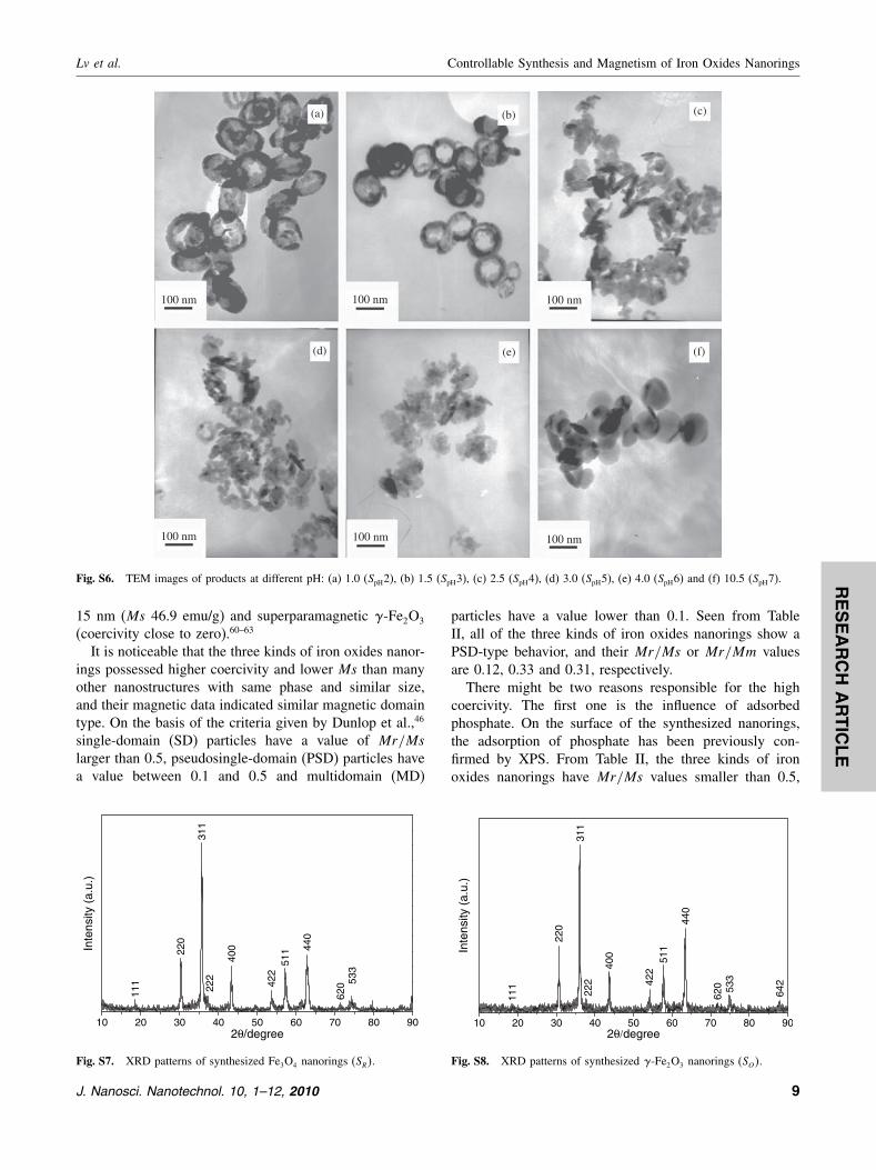
Fig. S6. TEM images of products at different pH: (a) 1.0 (SpH2), (b) 1.5 (SpH3), (c) 2.5 (SpH4), (d) 3.0 (SpH5), (e) 4.0 (SpH6) and (f) 10.5 (SpH7).
15 nm (Ms 46.9 emu/g) and superparamagnetic �-Fe2O3
(coercivity close to zero).60–63
It is noticeable that the three kinds of iron oxides nanor-ings possessed higher coercivity and lower Ms than manyother nanostructures with same phase and similar size,and their magnetic data indicated similar magnetic domaintype. On the basis of the criteria given by Dunlop et al.,46
single-domain (SD) particles have a value of Mr/Mslarger than 0.5, pseudosingle-domain (PSD) particles havea value between 0.1 and 0.5 and multidomain (MD)
10 20 30 40 50 60 70 80 90
620 53
3
440
511
422
400
222
311
220
Inte
nsity
(a.
u.)
2θ/degree
111
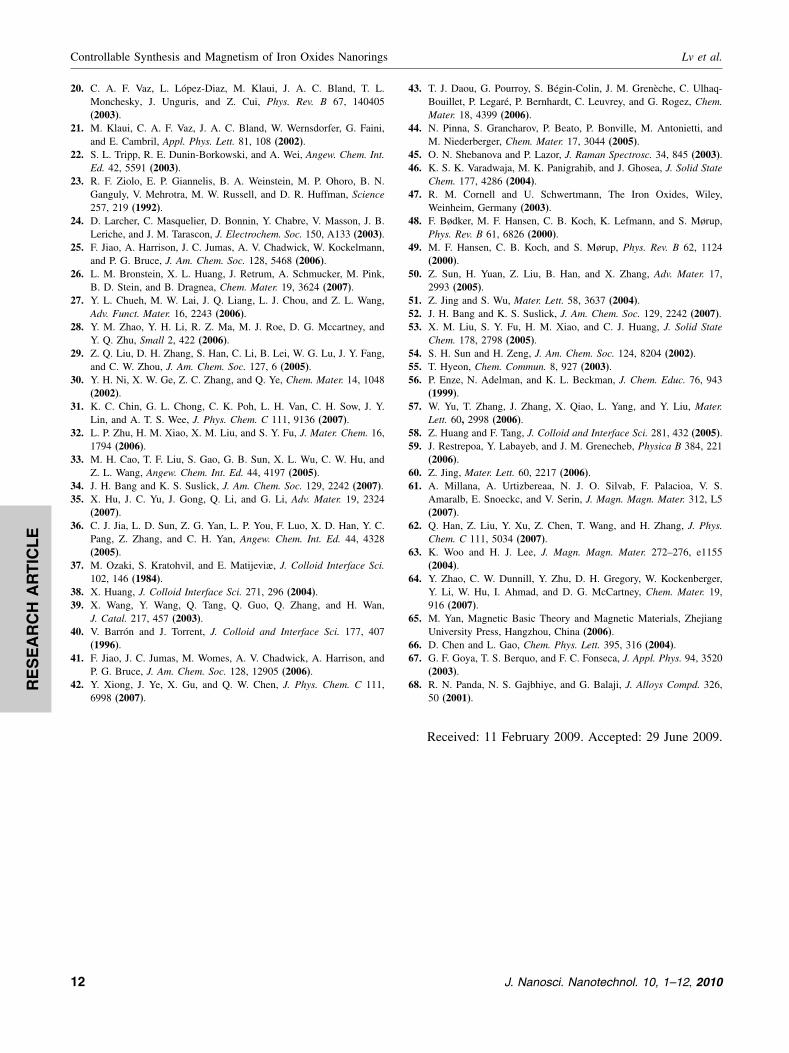
Fig. S7. XRD patterns of synthesized Fe3O4 nanorings (SR�.
particles have a value lower than 0.1. Seen from TableII, all of the three kinds of iron oxides nanorings show aPSD-type behavior, and their Mr/Ms or Mr/Mm valuesare 0.12, 0.33 and 0.31, respectively.
There might be two reasons responsible for the highcoercivity. The first one is the influence of adsorbedphosphate. On the surface of the synthesized nanorings,the adsorption of phosphate has been previously con-firmed by XPS. From Table II, the three kinds of ironoxides nanorings have Mr/Ms values smaller than 0.5,
10 20 30 40 50 60 70 80 90
642
620 53
3
440
511
42240
0
222
311
220
Inte
nsity
(a.
u.)
2θ/degree
111
Fig. S8. XRD patterns of synthesized �-Fe2O3 nanorings (SO�.
J. Nanosci. Nanotechnol. 10, 1–12, 2010 9

RE
SE
AR
CH
AR
TIC
LE
Controllable Synthesis and Magnetism of Iron Oxides Nanorings Lv et al.
indicating PSD-type or MD-type nanoparticles. Accordingto Gregory,64 there may be only one or two domains in thePSD particles, indicating that they might possess the char-acteristic magnetic properties of the SD and MD structures
M (
emu/
g)
–0.8
–0.6
–0.4
–0.2
0.0
0.2
0.4
0.6
0.8
464.98
Hc/kOe
Ms = 0.63 emu/gMr = 0.059 emu/gHc = 464.98 OeMr/Ms = 0.093
St4
–20 20151050
0
–5–10–15
900600300–300–600–900
M (
emu/
g)
–0.6
–0.4
–0.2
0.0
0.2
0.4
0.6
371.58
Hc/kOe
Ms = 0.50 emu/g
Mr = 0.052 emu/g
Hc = 371.58 Oe
Mr/Ms = 0.104
Stn
–20 20151050
0
–5–10–15
900600300–300–600–900
M (
emu/
g)
–0.6
–0.4
–0.2
0.0
0.2
0.4
0.6
501.56
Hc/kOe
Ms = 0.48 emu/g
Mr = 0.0458 emu/g
Hc = 501.56 Oe
Mr/Ms = 0.095
St5
900600300–600–300–900
–20 20151050
0
–5–10–15
M (
emu/
g)
–40
–20
0
20
334.94
Hc/kOe
Ms = 27.23 emu/g
Mr = 9.02 emu/g
Hc = 334.94 Oe
Mr/Ms = 0.33
SR
40
–20 20151050
0
–5–10–15
600400200–200–400–600
–20–0.4
–0.2
0.0
M (
emu/
g)
0.2
0.4
–1000
944.18
Hc/kOe
Ms = 0.31 emu/g
Mr = 0.0367 emu/g
Hc = 944.18 Oe
Mr/Ms = 0.118
ST4
20151050
0
–5–10–15
1000500–500
M (
emu/
g)
–0.4
–0.2
0.0
0.2
0.4
452.91
Hc/kOe
Ms = 0.38 emu/gMr = 0.031 emu/gHc = 452.91 OeMr/Ms = 0.082
St2
–20 20
900600300–300–600–900
151050
0
–5–10–15
M (
emu/
g)
–40
–20
0
20
40
266.24
Hc/kOe
Ms = 29.48 emu/gMr = 9.07 emu/gHc = 266.24 OeMr/Ms = 0.31
SO
–20 20151050
0
–5–10–15
600400200–200–400–600
Fig. S9. M–H loops of sample ST 4, SR, SO , St2, Sn, St4, and St5.
simultaneously. If the synthesized nanorings possess moreproperties of MD structures, the magnetic domain wallswould exist in the particles, especially for �-Fe2O3 nanor-ings, which might be MD particles. For MD particles, the
10 J. Nanosci. Nanotechnol. 10, 1–12, 2010

RE
SE
AR
CH
AR
TIC
LE
Lv et al. Controllable Synthesis and Magnetism of Iron Oxides Nanorings
movement of magnetic domain walls is the main reasonfor the coercivity. It is well known that there are sur-face domain walls existing on the surface of particles, andtheir movement could be easily blocked by the adsorbedphosphate layer.65 It indicates that the domain wall pin-ning would occur, which is the most important reason forhigh coercivity in MD particles. For SD particles, mag-netic domain walls don’t exist, and spin flip conversion ismainly responsible for the coercivity. In this case, coordi-nation bonds between adsorbed phosphate layer and ironoxide would form spin pinning and block spin flip con-version. And this will directly result in the increase ofcoercivity. Therefore, if the synthesized products possessmore properties of SD particles, the coercivity would alsoincrease. To confirm the effect of the adsorbed phosphate,a comparison was done between the �-Fe2O3 nanodisksin sample St2 and another �-Fe2O3 nanodisks (130 nm indiameter) synthesized without the presence of phosphate(sample Sn�.
66 As shown in Table II, sample St2 have acoercivity of 452.91 Oe and sample Sn only have a coer-civity of 371.58 Oe. This indicated that the presence ofphosphate indeed increased the coercivity of the nanorings.
The nanoring morphology of the particles might bethe second reason for the high coercivity. López-Urías16
reported the micromagnetic simulation of iron nanorings,and they found large coercive fields for nanorings whosedin/dout value (din and dout are the inner and outer diame-ters of the rings, respectively) is bigger than 0.5, due to theabsence of the vortex states and the presence of out-planeand in-plane spin configurations. Most of the nanorings insample ST 4 have a din/dout value about 0.6, so the nanoringmorphology might have contribution to the high coercivity.To confirm the effect of the ring shape, the magnetiza-tion of nanorings with smaller inner diameter were tested.As shown in Table II, the coercivity of �-Fe2O3 nanor-ings with din/dout value of 0.2 and 0.4 (corresponding tosample St4 and St5) are 464.98 Oe and 501.56 Oe, respec-tively. Considering 452.91 Oe of sample St2 (din/dout = 0,Fig. 3(b)) and 944.18 Oe of sample ST 4 (din/dout = 0�6), itis easy to find that the coercivity increased with the innerdiameter of nanorings. Compared the coercivity of sampleSt2, St4, St5 and ST 4, there should be a rapid increasewhen the din/dout value is close to 0.5, which well agreedwith the previously reported simulation result.16 However,identifying the accurate critical value is not an easy thing.This is because the “dissolution” process for each particlewas not absolutely same with each other. Even though thisresult still can show the accuracy of the micromagneticsimulation given by López-Urías.16
The decrease in Ms is often observed in nanoparticlesand could be attributed to the surface contribution: spincanting, surface disorder, stoichiometry deviation, cationdistribution, and adsorbed species (water).67�68 Herein, thereduction of Ms could also be attributed to the existenceof adsorbed non-magnetic phosphate layer.
4. CONCLUSIONS
We described an effective method to prepare �-Fe2O3
nanorings without using any templates, and the obtainednanorings have an average din/dout value about 0.6. It wasfound that 240 �C, 0.05 g NaH2PO4, 48 h pH = 1.8 wasan appropriate condition for the formation of �-Fe2O3
nanorings. On the basis of serial experiments and charac-terizations, an “oriented dissolution and recrystallization”mechanism was proposed to explain the formation pro-cess of the nanoring structure. Fe3O4 nanorings could beobtained by reducing synthesized �-Fe2O3 nanorings, andthen �-Fe2O3 nanorings could be obtained by reoxidizingFe3O4 nanorings in air. The magnetic properties of thesenanorings were investigated, and all of the three kinds ofnanorings had higher coercivity and lower Ms than manyother nanostructures with similar size and same phase. Thecoercivities of the nanorings were found increase with theincrease of din/dout. The adsorbed phosphate and the nanor-ing morphology of these particles should be responsiblefor the high coercivities.
References and Notes
1. C. Burda, X. B. Chen, R. Narayanan, and M. A. El-Sayed, Chem.Rev. 105, 1025 (2005).
2. X. Y. Kong, Y. Ding, R. S. Yang, and Z. L. Wang, Science 303, 1348(2004).
3. F. Li, Y. Ding, P. X. Gao, X. Q. Xin, and Z. L. Wang, Angew. Chem.Int. Ed. 43, 5238 (2004).
4. Y. Peng, A. W. Xu, B. Deng, M. Antonietti, and H. Co1lfen, J. Phys.Chem. B 110, 2988 (2006).
5. B. Liu and H. C. Zeng, J. Am. Chem. Soc. 127, 18262 (2005).6. L. P. Jiang, S. Xu, J. M. Zhu, J. R. Zhang, J. J. Zhu, and H. Y. Chen,
Inorg. Chem. 43, 5877 (2004).7. J. J. Miao, R. L. Fu, J. M. Zhu, K. Xu, J. J. Zhu, and H. Y. Chen,
Chem. Commun. 3013 (2006).8. J. Paek, C. H. Lee, J. Choi, S. Y. Choi, A. Kim, J. W. Lee, and
K. Lee, Cryst. Growth Des. 7, 1378 (2007).9. J. G. Zhu, Y. F. Zheng, and G. A. Prinz, J. Appl. Phys. 87, 6668
(2000).10. J. Rothman, M. Klaui, L. López-Diaz, C. A. F. Vaz, A. Bleloch, J. A.
C. Bland, Z. Cui, and R. Speaks, Phys. Rev. Lett. 86, 1098 (2001).11. J. Aizpurua, P. Hanarp, D. S. Sutherland, M. Kall, G. W. Bryant,
and J. G. García de Abajo, Phys. Rev. Lett. 90, 57401 (2003).12. E. M. Q. Jariwala, P. Mohanty, M. B. Ketchen, and R. A. Webb,
Phys. Rev. Lett. 86, 1594 (2001).13. K. A. Matveev, A. I. Larkin, and L. I. Glazman, Phys. Rev. Lett. 89,
96802 (2002).14. R. P. Cowburn, A. O. Adeyeye, and M. E. Welland, Phys. Rev. Lett.
81, 5414 (1998).15. K. J. Kirk, J. N. Chapman, S. Mcvitie, P. R. Aitchison, and C. D.
W. Wilkinson, Appl. Phys. Lett. 75, 3683 (1999).16. J. J. Torres-Heredia, F. López-Urías, and E. Munoz-Sandoval,
J. Magn. Magn. Mater. 294, e1 (2005).17. L. López-Diaz, J. Rothman, M. Klaui, and J. A. C. Bland, IEEE
Trans. Magn. 36, 3151 (2000).18. M. Klaui, C. A. F. Vaz, J. Rothman, J. A. C. Bland, W. Wernsdorfer,
G. Faini, and E. Cambril, Phys. Rev. Lett. 90, 97202 (2003).19. X. Zhu, P. Grutter, V. Metlushko, B. Ilic, Y. Hao, F. J. Castano,
S. Haratani, C. A. Ross, B. Vogeli, and H. I. Smith, J. Appl. Phys.93, 8540 (2003).
J. Nanosci. Nanotechnol. 10, 1–12, 2010 11
RE
SE
AR
CH
AR
TIC
LE
Controllable Synthesis and Magnetism of Iron Oxides Nanorings Lv et al.
20. C. A. F. Vaz, L. López-Diaz, M. Klaui, J. A. C. Bland, T. L.Monchesky, J. Unguris, and Z. Cui, Phys. Rev. B 67, 140405(2003).
21. M. Klaui, C. A. F. Vaz, J. A. C. Bland, W. Wernsdorfer, G. Faini,and E. Cambril, Appl. Phys. Lett. 81, 108 (2002).
22. S. L. Tripp, R. E. Dunin-Borkowski, and A. Wei, Angew. Chem. Int.Ed. 42, 5591 (2003).
23. R. F. Ziolo, E. P. Giannelis, B. A. Weinstein, M. P. Ohoro, B. N.Ganguly, V. Mehrotra, M. W. Russell, and D. R. Huffman, Science257, 219 (1992).
24. D. Larcher, C. Masquelier, D. Bonnin, Y. Chabre, V. Masson, J. B.Leriche, and J. M. Tarascon, J. Electrochem. Soc. 150, A133 (2003).
25. F. Jiao, A. Harrison, J. C. Jumas, A. V. Chadwick, W. Kockelmann,and P. G. Bruce, J. Am. Chem. Soc. 128, 5468 (2006).
26. L. M. Bronstein, X. L. Huang, J. Retrum, A. Schmucker, M. Pink,B. D. Stein, and B. Dragnea, Chem. Mater. 19, 3624 (2007).
27. Y. L. Chueh, M. W. Lai, J. Q. Liang, L. J. Chou, and Z. L. Wang,Adv. Funct. Mater. 16, 2243 (2006).
28. Y. M. Zhao, Y. H. Li, R. Z. Ma, M. J. Roe, D. G. Mccartney, andY. Q. Zhu, Small 2, 422 (2006).
29. Z. Q. Liu, D. H. Zhang, S. Han, C. Li, B. Lei, W. G. Lu, J. Y. Fang,and C. W. Zhou, J. Am. Chem. Soc. 127, 6 (2005).
30. Y. H. Ni, X. W. Ge, Z. C. Zhang, and Q. Ye, Chem. Mater. 14, 1048(2002).
31. K. C. Chin, G. L. Chong, C. K. Poh, L. H. Van, C. H. Sow, J. Y.Lin, and A. T. S. Wee, J. Phys. Chem. C 111, 9136 (2007).
32. L. P. Zhu, H. M. Xiao, X. M. Liu, and S. Y. Fu, J. Mater. Chem. 16,1794 (2006).
33. M. H. Cao, T. F. Liu, S. Gao, G. B. Sun, X. L. Wu, C. W. Hu, andZ. L. Wang, Angew. Chem. Int. Ed. 44, 4197 (2005).
34. J. H. Bang and K. S. Suslick, J. Am. Chem. Soc. 129, 2242 (2007).35. X. Hu, J. C. Yu, J. Gong, Q. Li, and G. Li, Adv. Mater. 19, 2324
(2007).36. C. J. Jia, L. D. Sun, Z. G. Yan, L. P. You, F. Luo, X. D. Han, Y. C.
Pang, Z. Zhang, and C. H. Yan, Angew. Chem. Int. Ed. 44, 4328(2005).
37. M. Ozaki, S. Kratohvil, and E. Matijeviæ, J. Colloid Interface Sci.102, 146 (1984).
38. X. Huang, J. Colloid Interface Sci. 271, 296 (2004).39. X. Wang, Y. Wang, Q. Tang, Q. Guo, Q. Zhang, and H. Wan,
J. Catal. 217, 457 (2003).40. V. Barrón and J. Torrent, J. Colloid and Interface Sci. 177, 407
(1996).41. F. Jiao, J. C. Jumas, M. Womes, A. V. Chadwick, A. Harrison, and
P. G. Bruce, J. Am. Chem. Soc. 128, 12905 (2006).42. Y. Xiong, J. Ye, X. Gu, and Q. W. Chen, J. Phys. Chem. C 111,
6998 (2007).
43. T. J. Daou, G. Pourroy, S. Bégin-Colin, J. M. Grenèche, C. Ulhaq-Bouillet, P. Legaré, P. Bernhardt, C. Leuvrey, and G. Rogez, Chem.Mater. 18, 4399 (2006).
44. N. Pinna, S. Grancharov, P. Beato, P. Bonville, M. Antonietti, andM. Niederberger, Chem. Mater. 17, 3044 (2005).
45. O. N. Shebanova and P. Lazor, J. Raman Spectrosc. 34, 845 (2003).46. K. S. K. Varadwaja, M. K. Panigrahib, and J. Ghosea, J. Solid State
Chem. 177, 4286 (2004).47. R. M. Cornell and U. Schwertmann, The Iron Oxides, Wiley,
Weinheim, Germany (2003).48. F. Bødker, M. F. Hansen, C. B. Koch, K. Lefmann, and S. Mørup,
Phys. Rev. B 61, 6826 (2000).49. M. F. Hansen, C. B. Koch, and S. Mørup, Phys. Rev. B 62, 1124
(2000).50. Z. Sun, H. Yuan, Z. Liu, B. Han, and X. Zhang, Adv. Mater. 17,
2993 (2005).51. Z. Jing and S. Wu, Mater. Lett. 58, 3637 (2004).52. J. H. Bang and K. S. Suslick, J. Am. Chem. Soc. 129, 2242 (2007).53. X. M. Liu, S. Y. Fu, H. M. Xiao, and C. J. Huang, J. Solid State
Chem. 178, 2798 (2005).54. S. H. Sun and H. Zeng, J. Am. Chem. Soc. 124, 8204 (2002).55. T. Hyeon, Chem. Commun. 8, 927 (2003).56. P. Enze, N. Adelman, and K. L. Beckman, J. Chem. Educ. 76, 943
(1999).57. W. Yu, T. Zhang, J. Zhang, X. Qiao, L. Yang, and Y. Liu, Mater.
Lett. 60, 2998 (2006).58. Z. Huang and F. Tang, J. Colloid and Interface Sci. 281, 432 (2005).59. J. Restrepoa, Y. Labayeb, and J. M. Grenecheb, Physica B 384, 221
(2006).60. Z. Jing, Mater. Lett. 60, 2217 (2006).61. A. Millana, A. Urtizbereaa, N. J. O. Silvab, F. Palacioa, V. S.
Amaralb, E. Snoeckc, and V. Serin, J. Magn. Magn. Mater. 312, L5(2007).
62. Q. Han, Z. Liu, Y. Xu, Z. Chen, T. Wang, and H. Zhang, J. Phys.Chem. C 111, 5034 (2007).
63. K. Woo and H. J. Lee, J. Magn. Magn. Mater. 272–276, e1155(2004).
64. Y. Zhao, C. W. Dunnill, Y. Zhu, D. H. Gregory, W. Kockenberger,Y. Li, W. Hu, I. Ahmad, and D. G. McCartney, Chem. Mater. 19,916 (2007).
65. M. Yan, Magnetic Basic Theory and Magnetic Materials, ZhejiangUniversity Press, Hangzhou, China (2006).
66. D. Chen and L. Gao, Chem. Phys. Lett. 395, 316 (2004).67. G. F. Goya, T. S. Berquo, and F. C. Fonseca, J. Appl. Phys. 94, 3520
(2003).68. R. N. Panda, N. S. Gajbhiye, and G. Balaji, J. Alloys Compd. 326,
50 (2001).
Received: 11 February 2009. Accepted: 29 June 2009.
12 J. Nanosci. Nanotechnol. 10, 1–12, 2010