control switch manual
TRANSCRIPT

Series 95 SwitSeries 95 Swit chesches
UL File No. E101598

Some of the typical standard applications for the Series 95 are:• Circuit-breaker control• Motor control• Voltmeter Selector and Transfer• Ammeter Selector and Transfer• Synchroscope Control• Control Selector Switch Applications
The Series 95 switches have the following standard features:Standard 3-hole Mounting #8-32 screw terminals• Nema class A Insulating materials (1050C )• Silver contact surfaces for long reliable life• Double-sided, double-wiping, knife-type rotary contacts
Special Features for Circuit Breaker Control switches include:• Mechanical red/green target• Slip contact for alarm and indicator circuits• Pull-to-Lock mechanism to return the switch handle to normal (vertical) position• Selection of Lighted Escutcheon plates
Special features for Meter Control switches include:• Make-Before-Break (shorting contacts for ammeter control)• Common-input Tap-Switch arrangement whereby the meter may be
sequentially connected to several lines using the same switching deck• Positive positioning detent mechanism• Pre-wired jumpers
Special features for synchroscope applications include:• Removable Oval Handles• Key lockable arrangements
The following details the most common applications, contact arrangements and escutcheon plate markings. For combination of contact arrangements, handles,escutcheon plate marking and special features not shown, contact the factory for availability.
‘s Instrument and Control Switch is a heavy-duty rotary switch that satisfies the most demanding requirements of the industrial control and power applications. These switches are 600V AC rated and are recognized by Underwriters Laboratories in the
United States and Canada.
®
INSTRUMENT AND CINSTRUMENT AND CONTRONTROL SWITOL SWITCHCH
www.GEMultilin.com
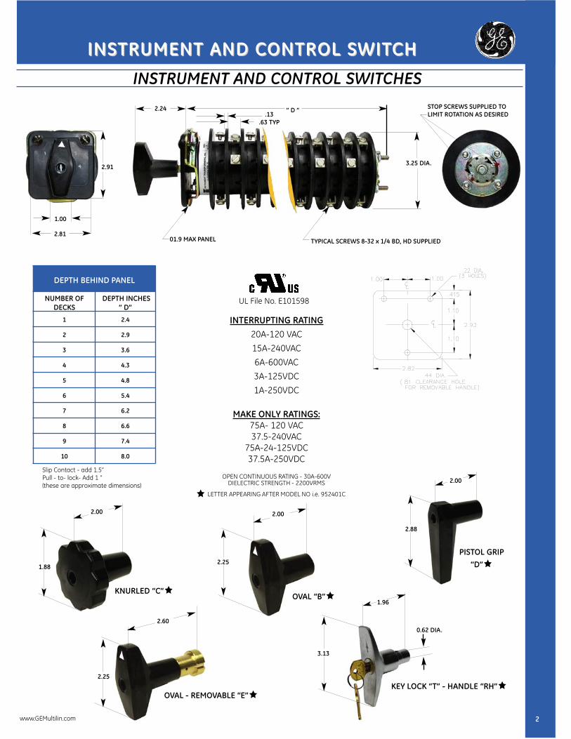
INSTRUMENT AND CONTROL SWITCHES
” D ”
2.22 DIA.
3.25 DIA.
.13.63 TYP
2.25
01.9 MAX PANEL
1.00
2.81TYPICAL SCREWS 8-32 x 1/4 BD, HD SUPPLIED
STOP SCREWS SUPPLIED TOLIMIT ROTATION AS DESIRED
OVAL HANDLE
DEPTH BEHIND PANEL
NUMBER OFDECKS
DEPTH INCHES” D”
1 2.4
2 2.9
3 3.6
4 4.3
5 4.8
6 5.4
7 6.2
8 6.6
9 7.4
10 8.0
Slip Contact - add 1.5”Pull - to- lock- Add 1 ”(these are approximate dimensions)
2.25
2.002.00
2.60
1.96
2.00
OVAL - REMOVABLE “E”
KNURLED “C”
KEY LOCK “T” - HANDLE “RH”
OVAL “B”
PISTOL GRIP“D”1.88
2.25
3.13
2.88
2
INSTRUMENT AND CINSTRUMENT AND CONTRONTROL SWITOL SWITCHCH
2.24
INTERRUPTING RATING20A-120 VAC15A-240VAC6A-600VAC3A-125VDC1A-250VDC
MAKE ONLY RATINGS:75A- 120 VAC37.5-240VAC
75A-24-125VDC37.5A-250VDC
OPEN CONTINUOUS RATING - 30A-600VDIELECTRIC STRENGTH - 2200VRMS
LETTER APPEARING AFTER MODEL NO i.e. 952401C
0.62 DIA.
2.91
UL File No. E101598
www.GEMultilin.com
INSTRUMENT AND CINSTRUMENT AND CONTRONTROL SWITOL SWITCHCH
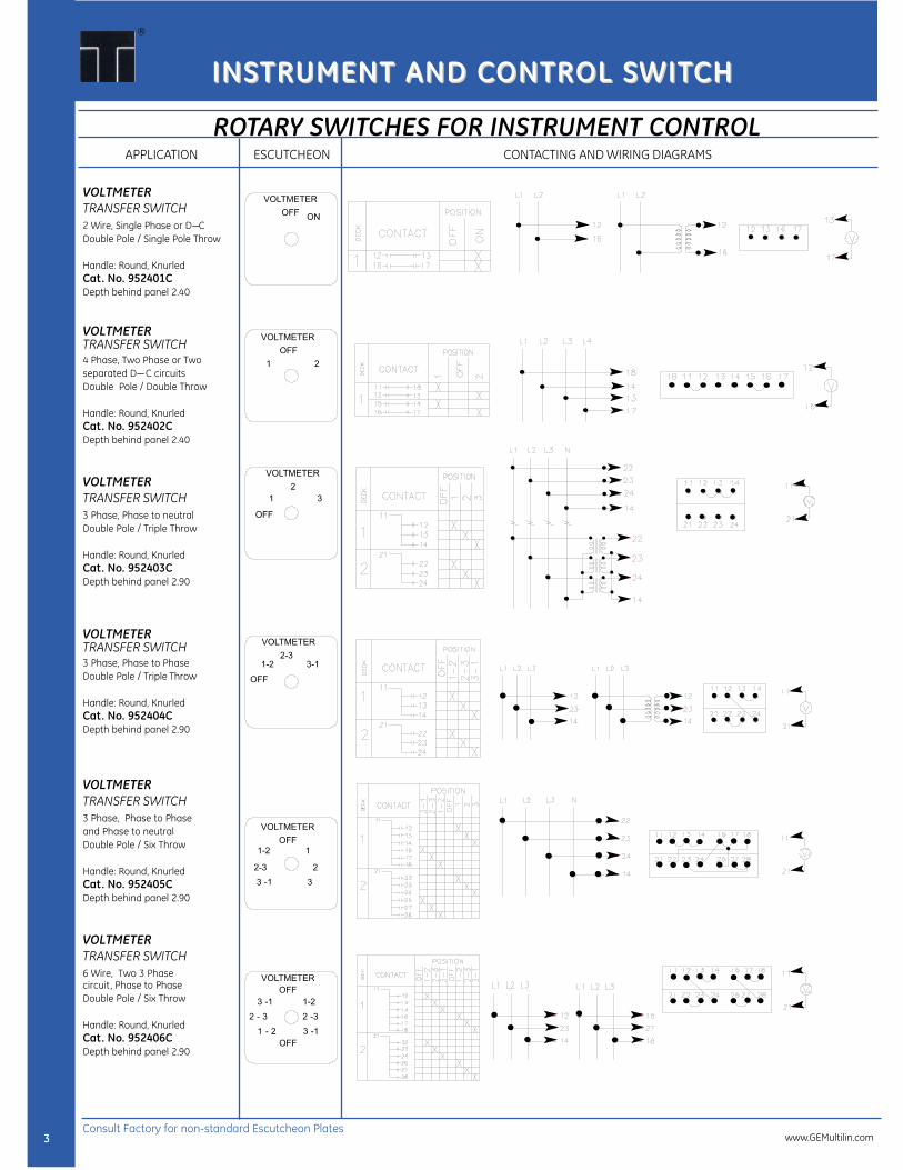
VOLTMETERTRANSFER SWITCH2 Wire, Single Phase or D—CDouble Pole / Single Pole Throw
Handle: Round, KnurledCat. No. 952401CDepth behind panel 2.40
VOLTMETERTRANSFER SWITCH4 Phase, Two Phase or Twoseparated D—C circuitsDouble Pole / Double Throw
Handle: Round, KnurledCat. No. 952402CDepth behind panel 2.40
VOLTMETERTRANSFER SWITCH3 Phase, Phase to neutralDouble Pole / Triple Throw
Handle: Round, KnurledCat. No. 952403CDepth behind panel 2.90
VOLTMETERTRANSFER SWITCH3 Phase, Phase to PhaseDouble Pole / Triple Throw
Handle: Round, KnurledCat. No. 952404CDepth behind panel 2.90
VOLTMETERTRANSFER SWITCH3 Phase, Phase to Phaseand Phase to neutralDouble Pole / Six Throw
Handle: Round, KnurledCat. No. 952405CDepth behind panel 2.90
VOLTMETERTRANSFER SWITCH6 Wire, Two 3 Phase circuit, Phase to PhaseDouble Pole / Six Throw
Handle: Round, KnurledCat. No. 952406CDepth behind panel 2.90
ROTARY SWITCHES FOR INSTRUMENT CONTROL
VOLTMETER
OFFON
VOLTMETER
OFF
1 2
VOLTMETER
2
1 3
OFF
VOLTMETER
2-3
1-2 3-1
VOLTMETER
OFF
1-2 1
VOLTMETER
OFF
3 -1 1-2
2 - 3 2 -3
1 - 2 3 -1
OFF
9510D - 2V14
9510C - 3V14
9510C - 4V15
9510C - 4 V21
9510E -7V24
9510E - 8V33
OFF
2-3 2
3 -1 3
APPLICATION
3
CONTACTING AND WIRING DIAGRAMSESCUTCHEON
®
Consult Factory for non-standard Escutcheon Plateswww.GEMultilin.com
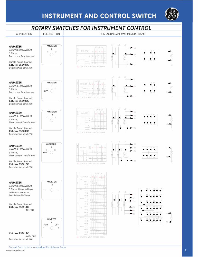
ROTARY SWITCHES FOR INSTRUMENT CONTROL
AMMETERTRANSFER SWITCH3 Phase ,Two current Transformers
Handle: Round, KnurledCat. No. 952407CDepth behind panel 2.90
AMMETERTRANSFER SWITCH3 Phase ,Two current Transformers
Handle: Round, KnurledCat. No. 952408CDepth behind panel 2.90
AMMETERTRANSFER SWITCH3 Phase ,Three current Transformers
Handle: Round, KnurledCat. No. 952409CDepth behind panel 2.90
AMMETERTRANSFER SWITCH3 Phase ,Three current Transformers
Handle: Round, KnurledCat. No. 952410CDepth behind panel 2.90
AMMETERTRANSFER SWITCH3 Phase , Phase to Phase and Phase to neutral Double Pole Six Throw
Handle: Round, KnurledCat. No. 952411C
(NO OFF)
Cat. No. 952412C(WITH OFF)
Depth behind panel 5.40
AMMETER
2
1 3
AMMETER
2
1 3
AMMETER
2
1 3
OFF
AMMETER
2
1 3
AMMETER
2
OFF OFF
1 3
AMMETER
2
1 3
OFF
9510C- 3A10A
9510C - 4A13
9510C - 3A10A
9510C - 4A13
9510A - 3A10
9510C - 5A16
4
APPLICATION CONTACTING AND WIRING DIAGRAMSESCUTCHEON
INSTRUMENT AND CINSTRUMENT AND CONTRONTROL SWITOL SWITCHCH
Consult Factory for non-standard Escutcheon Plateswww.GEMultilin.com

INSTRUMENT AND CINSTRUMENT AND CONTRONTROL SWITOL SWITCHCH
ROTARY SWITCHES FOR INSTRUMENT CONTROL
WATTMETER
OFFON
AMMETER-VOLTMETER
2
1 3
OFF
WATTMETER
OFFON
9510D - 2W14
9510D - 2W14
9510C - 3W16
9510D- 2P14
9511D -2S17
P.F. METER
OFFON
SYNCHROSCOPE
OFFON
WATTMETER
OFFW RVA
AMMETER-VOLTMETERTRANSFER SWITCH3 Phase , Phase to PhaseThree current Transformers
Handle: Round, KnurledCat. No. 952415CDepth behind panel 4.30
WATTMETERTRANSFER SWITCH3 Phase ,Three current TransformersThree current PotentialTransformers
Handle: Round, KnurledCat. No. 952419CDepth behind panel 3.60
WATTMETERTRANSFER SWITCH3 Phase ,Two current TransformersTwo current CoilsTwo potentials Coils
Handle: Round, KnurledCat. No. 952420CDepth behind panel 3.60
WATTMETERREVERSING SWITCH
Handle: Round, KnurledCat. No. 952421CDepth behind panel 2.90
POWER-FACTORSWITCH3 Phase ,Two current TransformersOne or Two current Coils
Handle: Round, KnurledCat. No. 952422CDepth behind panel 2.40
SYNCHRONIZINGSWITCHMachine to bus with interlocks
Handle: Oval, removableCat. No. 952424EDepth behind panel 2.90
5
APPLICATION CONTACTING AND WIRING DIAGRAMSESCUTCHEON
®
Consult Factory for non-standard Escutcheon Plates
9510C - 4A23C
www.GEMultilin.com

INSTRUMENT AND CINSTRUMENT AND CONTRONTROL SWITOL SWITCHCH
ROTARY SWITCHES FOR INSTRUMENT CONTROL
MOTOR CONTROLSWITCHGOVERNOR OR RHEOSTATSplit field motor
Handle: Pistol grip, Spring returnCat. No. 952427DDepth behind panel 2.40
CIRCUIT BREAKERTRIP SWITCHDouble Pole / Single Throwcontacts normally openHandle: Pistol grip, Spring returnCat. No. 952436DDepth behind panel 2.40
CIRCUIT BREAKERCONTROL SWITCH
Handle: Pistol grip,Spring returnCat. No. 952438DDepth behind panel 2.40
CIRCUIT BREAKERCONTROL SWITCH
Handle: Pistol grip, Spring returnCat. No. 952440DDepth behind panel 2.40
CIRCUIT BREAKERCONTROL SWITCHOperate two breaker
Handle: Pistol grip, Spring returnCat. No. 952441DDepth behind panel 2.40
CIRCUIT BREAKERCONTROL SWITCHOperate two breaker
Handle: Pistol grip,Spring returnCat. No. 952442DDepth behind panel 4.30
9510B-2M22
9510D -1B18
9518B - 2B23
9518B -2B23
9518B -2B23
9518B -2B23
MOTOR CONTROL
RAISE LOWER
BREAKER CONTROL
TRIP
BREAKER CONTROL
TRIP CLOSE
BREAKER CONTROL
TRIP CLOSE
BREAKER CONTROL
TRIP CLOSE
BREAKER CONTROL
TRIP CLOSE
6
CONTACTING AND WIRING DIAGRAMSESCUTCHEONAPPLICATION
Consult Factory for non-standard Escutcheon Plateswww.GEMultilin.com

INSTRUMENT AND CINSTRUMENT AND CONTRONTROL SWITOL SWITCHCH
ROTARY SELECTOR SWITCHES
CIRCUIT BREAKERCONTROL SWITCH
Handle: Pistol grip, Spring returnCat. No. 952443DDepth behind panel 4.70
CIRCUIT BREAKERCONTROL SWITCH
Handle: Pistol grip, Spring returnCat. No. 952444DDepth behind panel 4.70
CIRCUIT BREAKERCONTROL SWITCH
Handle: Pistol grip,Spring returnCat. No. 952445DDepth behind panel 5.40
CIRCUIT BREAKERCONTROL SWITCH
Handle: Pistol grip,Spring returnCat. No. 952446DDepth behind panel 5.40
CIRCUIT BREAKERCONTROL SWITCH
Handle: Pistol grip, Spring returnCat. No. 952450DDepth behind panel 4.70
CIRCUIT BREAKERCONTROL SWITCH
Handle: Pistol grip,Spring returnCat. No. 952452DDepth behind panel 6.90
9518B -2B23
9518B -2B23
9518B -2B23
9518B -2B23
9519C-3B33
9518B -2B23
BREAKER CONTROL
TRIP CLOSE
BREAKER CONTROL
TRIP CLOSE
BREAKER CONTROL
TRIP CLOSE
BREAKER CONTROL
TRIP CLOSE
BREAKER CONTROL
TRIP CLOSE
PULL-TO
LOCK
7
CONTACTING AND WIRING DIAGRAMSAPPLICATION ESCUTCHEON
BREAKER CONTROL
TRIP CLOSE
PULL-TO
LOCK
®
Consult Factory for non-standard Escutcheon Plateswww.GEMultilin.com

INSTRUMENT AND CINSTRUMENT AND CONTRONTROL SWITOL SWITCHCH
ROTARY SELECTOR SWITCHES
9518B -2B23
9518C -2B23
CIRCUIT BREAKERCONTROL SWITCH
UNIVERSALCIRCUIT
Handle: Pistol grip, Spring returnCat. No. 952457DDepth behind panel 6.20
CIRCUIT BREAKERCONTROL SWITCH
UNIVERSALCIRCUIT
Handle: Pistol grip, Spring returnCat. No. 952458DDepth behind panel 8.00
BREAKER CONTROL
TRIP CLOSE
BREAKER CONTROL
TRIP CLOSE
PULL-TO
LOCK
CONTACTING AND WIRING DIAGRAMSESCUTCHEONAPPLICATION
8
Consult Factory for non-standard Escutcheon Plates
www.GEMultilin.com

INSTRUMENT AND CINSTRUMENT AND CONTRONTROL SWITOL SWITCHCH
DETENT SELECTOR SWITCH
OFF - ONSWITCHSINGLE - THROW
1
DOUBLETHROWSWITCH
(WITH OFF)
3
DOUBLETHROWSWITCHSINGLE - THROWSpring return
5DOUBLETHROWSWITCHSpring return
(WITH OFF)
6
OFF - ONSWITCHSINGLE - THROWSpring return
4
** The catalog numbers are for universalswitches that provide all contacting shown.Oval handle supplied.To limit switches to positions shown put limitscrews in holes in rear stop plate shown as“Stops”.Order jumpers as required, as separate items.
** The catalog numbers are for universalswitches that provide all contacting shown.Oval handle supplied.To limit switches to positions shown put limitscrews in holes in rear stop plate shown as“Stops”.
Order jumpers as required, as separate items.
DECKS CATALOG NO. INCHES*
1 9524201B 2.4
2 9524202B 2.9
3 9524203B 3.6
4 9524204B 4.3
5 9524205B 4.8
6 9524206B 5.4
7 9524207B 6.2
8 9524208B 6.6
9 9524209B 7.4
10 9524210B 8.0
DECKS CATALOG NO. INCHES*
1 9574201B 2.4
2 9574202B 2.9
3 9574203B 3.6
4 9574204B 4.3
5 9574205B 5.3
* DEPTH BEHIND PANEL
1 & 7
1 & 7
2 & 7
2 & 7
1 & 7
1 & 7
DOUBLETHROWSWITCH
(ON OFF)
2
DESCRIPTION
DESCRIPTION
CONTACTING AND WIRING DIAGRAMS
CONTACTING AND WIRING DIAGRAMS
CATALOG NUMBERS
CATALOG NUMBERS
STOPS
STOPS
9
®
MOMENTARY (SPRING RETURN) ACTION SWITCHES
The above switch will family will be provided as DEVELOPMENT 6 unless otherwise specified. By changing stop screw location and wiring connections the switch may be configuredby the consumer as DEVELOPMENTS 4 or 5. Escutcheon for DEVELOPMENT 6 provided as standard unless DEVELOPMENT 4 or 5 specified at time of order.
* DEPTH BEHIND PANEL
The above switch will family will be provided as DEVELOPMENT 3 unless otherwise specified. By changing stop screw location and wiring connections the switch may be configured by the consumer as DEVELOPMENTS 1 or 2. Escutcheon for DEVELOPMENT 3provided as standard unless DEVELOPMENT 1 or 2 specified at time of order. This External Jumper provided to allow common input to circuit 1 & 2. However removal of the Jumper does not isolate the two currents as these two terminals are tied together internally in the off position.
www.GEMultilin.com
INSTRUMENT AND CINSTRUMENT AND CONTRONTROL SWITOL SWITCHCH
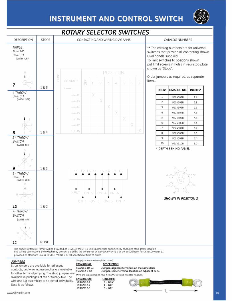
ROTARY SELECTOR SWITCHES
TRIPLETHROWSWITCH
(WITH OFF)
7
6 - THROWSWITCH
(WITH OFF)
107- THROWSWITCH
(WITH OFF)
11
** The catalog numbers are for universalswitches that provide all contacting shown.Oval handle supplied.To limit switches to positions shown put limit screws in holes in rear stop plateshown as “Stops”.
Order jumpers as required, as separateitems.
CONTACTING AND WIRING DIAGRAMSSTOPSDESCRIPTION CATALOG NUMBERS
DECKS CATALOG NO. INCHES*
1 9524301B 2.4
2 9524302B 2.9
3 9524303B 3.6
4 9524304B 4.3
5 9524305B 4.8
6 9524306B 5.4
7 9524307B 6.2
8 9524308B 6.6
9 9524309B 7.4
10 9524310B 8.0
JUMPERSStrap jumpers are available for adjacent contacts, and wire lug assemblies are availablefor other terminal jumping. The strap jumpers areavailable in packages of ten or twenty-five. Thewire and lug assemblies are ordered individually.Data is as follows:
(Strap jumpers are silver-plated brass.)
CATALOG NO:9502011-10-C39502012-2-C3(Wire and lug assemblies have #10 AWG wire and insulated ring lugs.)
CATALOG NO: LENGTH (L)95002012-1 3 - 1/16”95002012-2 4 - 1/4”95002012-3 3 - 5/8”
1 & 4
1 & 3
1 & 2
NONE
1 & 5
* DEPTH BEHIND PANEL
L 10
5 - THROWSWITCH
(WITH OFF)
9
4 THROWSWITCH
(WITH OFF)
8
DESCRIPTIONJumper, adjacent terminals on the same deck.Jumper, same terminal location on adjacent deck.
The above switch will family will be provided as DEVELOPMENT 11 unless otherwise specified. By changing stop screw locationand wiring connections the switch may be configured by the consumer as DEVELOPMENTS 7 or 10. Escutcheon for DEVELOPMENT 11provided as standard unless DEVELOPMENT 7 or 10 specified at time of order.
SHOWN IN POSITION 2
www.GEMultilin.com

INSTRUMENT AND CINSTRUMENT AND CONTRONTROL SWITOL SWITCHCH
SERIES 95 LOCK OUT RELAY SWITCHES
Notes:All switch assemblies include the following1. 1 - Escutcheon plate.2. 3 - No.10 - 32 x 5/8” screw.3 Pistol grip is shown on front cover.
Switches with 6 or more decks require 2nd torsion spring assembly.
Complete technical data is outlined in Technical Publication ITLOR95. (DTS-ITILOR95)
GENERALGENERAL PURPPURP OSEOSE RARATINGTING
30A 600V Open CARRY
20A 600V enclosed CARRY
20A 120VAC .8 PF, MAKE & BREAK
15A 240VAC .8 PF, MAKE & BREAK
6A 600VAC .8 PF, MAKE & BREAK
3A 125VAC RESISTIVE MAKE & BREAK
1A 250VAC RESISTIVE MAKE & BREAK
DEPTH BEHINDDEPTH BEHIND PPANELANEL
NUMBER OFDECKS
DEPTHINCHES” D”
1 3.6
2 4.3
3 4.7
4 5.5
5 6.2
6 7.5
7 8.1
8 8.5
9 9.2
10 9.6
DRILL PATTERNS &ESCUTCHEON PLATE DIMENSIONS
TYPICAL CONTACT DECKS SHOWN, THE EXTRA DECK IN FRONT IS FOR COIL CLEARING
(SHOWN WITHOUT HANDLEFOR CLARITY)
SEE NOTE4 *
.13.63 TYP
“ D”
11
®
www.GEMultilin.com
4.75
3.00
1.75
UL File No. E101598

INSTRUMENT AND CINSTRUMENT AND CONTRONTROL SWITOL SWITCHCH
LOCK OUT RELAY SWITCHES
COIL COILCKT
VOLTAGE
COIL CURRENT@ NORMAL
VOLTAGEOPERATING
RANGE
COIL CURRENT@ MAXIMUM VOLTAGEOF OPERATING RANGE
COILRESISTANT
@ 250C
A 24VDC 7.3 10-40VDC 12.2 AMPS DC 3.3
B 24VDC 3.2 18-50VDC 6.5 AMPS DC 7.7
C 48VDC 3.7 24-70VDC 5.4 AMPS DC 13
D 125VDC 4.6 30-140VDC 5.2 AMPS DC 27
E 125VDC 2.5 45-150VDC 2.8 AMPS DC 50
F 250VDC 2.4 70-280VDC 2.7 AMPS DC 104
DECKS10-40VDC
A COIL
18-50VDC
B COIL
24-70VDC
C COIL
30-140VDC
D COIL
45-140VDC
E COIL
70-280VDC
F COIL
1 957801A 957801B 957801C 957801D 957801E 957801F
2 957802A 957802B 957802C 957802D 957802E 957802F
3 957803A 957803B 957803C 957803D 957803E 957803F
4 957804A 957804B 957804C 957804D 957804E 957804F
5 957805A 957805B 957805C 957805D 957805E 957805F
6 957806A 957806B 957806C 957806D 957806E 957806F
7 957807A 957807B 957807C 957807D 957807E 957807F
8 957808A 957808B 957808C 957808D 957808E 957808F
9 957809A 957809B 957809C 957809D 957809E 957809F
10 957810A 957810B 957810C 957810D 957810E 957810F
TYPICAL SWITCH DEVELOPMENTFOR DECKS 1 THRU 10
WHERE “n” IS DECK NUMBER
* D COIL HAS BEEN TESTED AND APPROVED FOR USE AT 120V AC
MANUAL RESET LORMANUAL RESET LOR CONTACT DECK LAYOUT
n=deck number
OPERATING DC VOLTS
LOR TRIP COILSTO USE
.2 A TARGET . 2 A TARGET
150125
A, B, CB,C,D,E
150125140
D,E,FD,E,FD,E,F
DD
190250
FF
DD
LORTRIPCOIL
NO ADDITIONALCIRCUITY(TARGET)
2A TARGETRESISTOR (R0)IN PARALLEL
2A TARGETRC CIRCUIT
2A TARGETSERIES
RESISTOR (RS)
.2A .6A .2A25
OHMS50
OHMS40
OHMS20
OHMS7
OHMS12.3
OHMS16.7
OHMS
AB 12 12 42 90
90
CD 24 40 118 80 95 105
95
EF 40 150
7570
150125
12www.GEMultilin.com
INSTRUMENT AND CINSTRUMENT AND CONTRONTROL SWITOL SWITCHCH
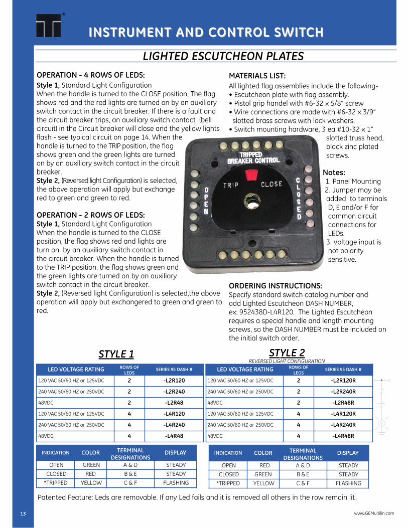
OPERATION - 4 ROWS OF LEDS:Style 1, Standard Light ConfigurationWhen the handle is turned to the CLOSE position, The flagshows red and the red lights are turned on by an auxiliaryswitch contact in the circuit breaker. If there is a fault andthe circuit breaker trips, an auxiliary switch contact (bellcircuit) in the Circuit breaker will close and the yellow lightsflash - see typical circuit on page 14. When the handle is turned to the TRIP position, the flag shows green and the green lights are turned on by an auxiliary switch contact in the circuit breaker.Style 2, (Reversed light Configuration) is selected, the above operation will apply but exchange red to green and green to red.
OPERATION - 2 ROWS OF LEDS:Style 1, Standard Light ConfigurationWhen the handle is turned to the CLOSE position, the flag shows red and lights are turn on by an auxiliary switch contact in the circuit breaker. When the handle is turned to the TRIP position, the flag shows green and the green lights are turned on by an auxiliary switch contact in the circuit breaker.Style 2, (Reversed light Configuration) is selected,the aboveoperation will apply but exchangered to green and green tored.
MATERIALS LIST:All lighted flag assemblies include the following-• Escutcheon plate with flag assembly.• Pistol grip handel with #6-32 x 5/8” screw• Wire connections are made with #6-32 x 3/9”
slotted brass screws with lock washers.• Switch mounting hardware, 3 ea #10-32 x 1”
slotted truss head, black zinc plated screws.
Notes:1. Panel Mounting2. Jumper may be added to terminals D, E and/or F for common circuit connections for LEDs.
3. Voltage input isnot polaritysensitive.
ORDERING INSTRUCTIONS:Specify standard switch catalog number andadd Lighted Escutcheon DASH NUMBER, ex: 952438D-L4R120. The Lighted Escutcheon requires a special handle and length mountingscrews, so the DASH NUMBER must be included onthe initial switch order.
LIGHTED ESCUTCHEON PLATES
INDICATION COLOR TERMINALDESIGNATIONS
DISPLAY
OPEN GREEN A & D STEADYCLOSED RED B & E STEADY
*TRIPPED YELLOW C & F FLASHING
INDICATION COLOR TERMINALDESIGNATIONS
DISPLAY
OPEN RED A & D STEADYCLOSED GREEN B & E STEADY
*TRIPPED YELLOW C & F FLASHING
LED VOLTAGE RATING ROWS OFLEDS
SERIES 95 DASH #
120 VAC 50/60 HZ or 125VDC 2 -L2R120
240 VAC 50/60 HZ or 250VDC 2 -L2R240
48VDC 2 -L2R48
120 VAC 50/60 HZ or 125VDC 4 -L4R120
240 VAC 50/60 HZ or 250VDC 4 -L4R240
48VDC 4 -L4R48
STYLE 1
13
®
Patented Feature: Leds are removable. If any Led fails and it is removed all others in the row remain lit .
LED VOLTAGE RATING ROWS OFLEDS
SERIES 95 DASH #
120 VAC 50/60 HZ or 125VDC 2 -L2R120R
240 VAC 50/60 HZ or 250VDC 2 -L2R240R
48VDC 2 -L2R48R
120 VAC 50/60 HZ or 125VDC 4 -L4R120R
240 VAC 50/60 HZ or 250VDC 4 -L4R240R
48VDC 4 -L4R48R
STYLE 2REVERSED LIGHT CONFIGURATION
www.GEMultilin.com

INSTRUMENT AND CINSTRUMENT AND CONTRONTROL SWITOL SWITCHCH
LIGHTED ESCUTCHEON PLATES
REAR VIEW
14
ESCUTCHEON ASSEMBLYFRONT COVER WITH FLAG
2 ROWS OF LEDS PART# 1729C248224 ROWS OF LEDS PART# 1729C24867
MOLDED PISTOLGRIP HANDLE
PART# 1729B20856
PROTRUSION OF LEDSWHEN FULLY ASSEMBLED
2 DECKS SERIES 95 SWITCHASSEMBLY
STANDARD OUTLINE, NOTMODEL SPECIFIC
CUSTOMER PANEL
DRILL PATTERN
QTY PART # COLOR6 LED—MV6351 YELLOW6 LED—MV6451 GREEN6 LED—MV6951 RED
Notes:1. LEDS are removable and inserted by the use of needle nose pliers2. Polarity should be observed during installation.3. Molded escutcheon panel LED ports are polarized.
www.GEMultilin.com

Series 95 Switches CS00A40786 Rev.2 10/09
USA, Canada, Asia, Latin AmericaTel: +1-800-547-8629Fax: +1-905-201-2455
e-mail: [email protected]
Europe, Middle East, AfricaTel: +34-94-485-88-00Fax: +34-94-485-88-45
e-mail: [email protected]
Please refer to our website www.GEMultilin.com for more detailed contact information