control schemes for shock mitigation using adaptive shock ... · control schemes for shock...
TRANSCRIPT
Control Schemes for Shock Mitigation Using Adaptive Shock Absorbers
AIAAAIAA--SDM 2012SDM 2012
PhD Candidate
Harinder J. SinghMinta Martin Professor and Chair
Dr. Norman M. Wereley
Seventh Triennial International Fire and Cabin Safety Research Conference, Philadelphia, PA Dec 2-5, 2013
Department of Aerospace Engineering, University of Maryland, College Park, MD
Associate Research Scientist
Dr. Wei Hu

Objective
Large lumbar load transmissions to the seated occupantsexposed to crash/impact events
Landmine blast of armored vehiclesHelicopter hard landing
To develop an adaptive occupant protection seat suspensionfor minimizing transmitted lumbar loads during shock events
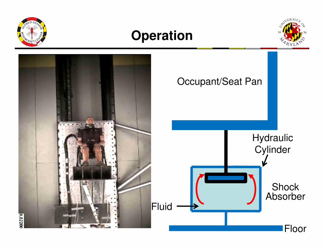
Operation
Occupant/Seat Pan
Shock Absorber
Floor
Hydraulic
Cylinder
Fluid

Outline
Design and Testing of Magnetorheological Energy Absorber
Control Algorithms
– Constant Stroking Load Control
– Terminal Trajectory Control
ConclusionsConclusions

Magnetorheological Fluid
Magnetic
Particles
Shear Stress ττττ > 0Shear Stress ττττ > ττττy
N
S
Chain
Formation
• Magnetic field induces change in viscosity of MR fluid
• Formation of chains of magnetic particles due to magnetic induction
• Yield behavior results at a shear stress leading to breaking of chains
No FieldMagnetic Field
N
S

MREA Configuration
Double-ended MREA with multi-stage electromagnetic coils.
MREA Stroking Load: Yield force (controllable) & Viscous force (passive)

MREA Analysis
Pressure Drop Regions
• Entrance effect from region 1-2.
• Sudden expansion from region 2-3, 4-5 and 6-7.
• Sudden contraction from region 3-4, 5-6, 7-8.
• Exit effect from region 8-9.
• Viscous Darcy friction losses in coil gap 3, 5 and 7.
• Viscous Darcy friction losses in MR valve 2, 4, 6 and 8.
• MR effect pressure losses in MR valve 2, 4, 6 and 8.
Pressure Drop Regions
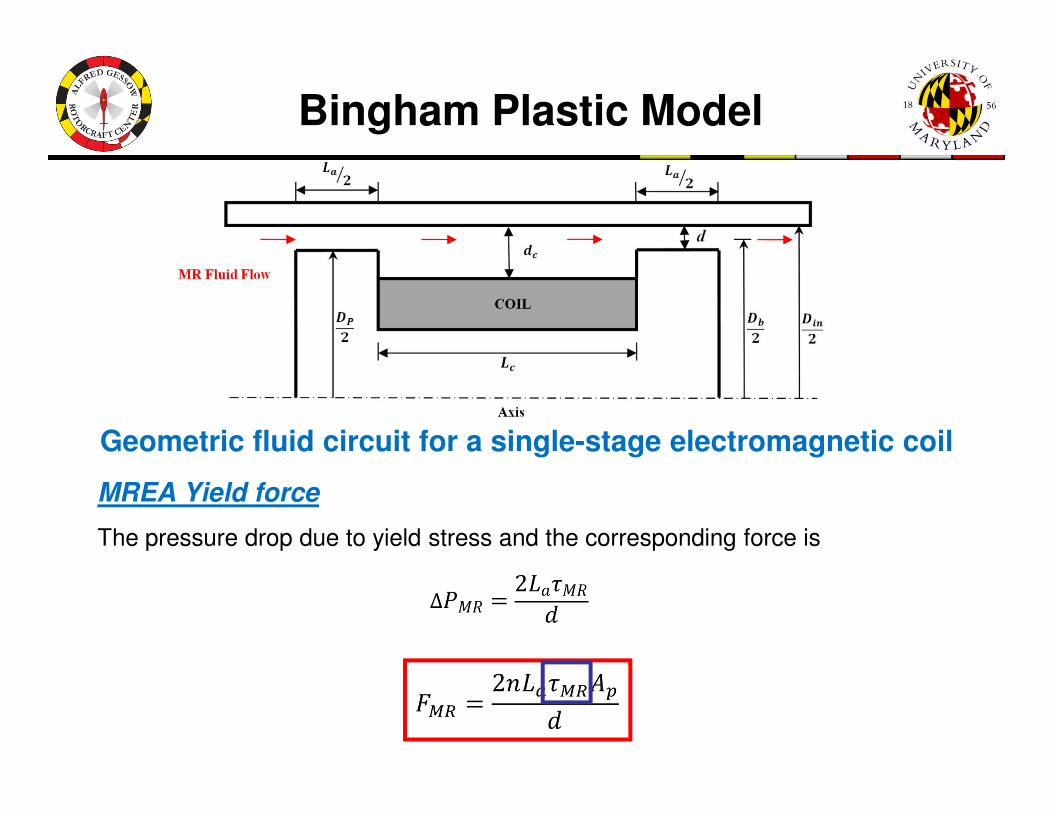
Bingham Plastic Model
MREA Yield force
The pressure drop due to yield stress and the corresponding force is
Geometric fluid circuit for a single-stage electromagnetic coil
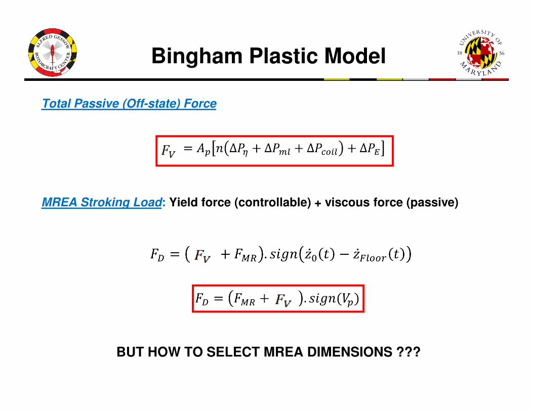
Bingham Plastic Model
Total Passive (Off-state) Force
MREA Stroking Load: Yield force (controllable) + viscous force (passive)MREA Stroking Load: Yield force (controllable) + viscous force (passive)
BUT HOW TO SELECT MREA DIMENSIONS ???

Controllability Envelope Optimization
Schematic of controllability envelope of MREA
Quadratic variation α Vp2
Max
Ideal Controllability
Envelope
DR approaches 1 at higher velocities
because of increased off-state forcesRe (Reynold’s Number)Re (Reynold’s Number)
(Mao, Choi, & Wereley, 2005)

Optimized MREA
• Increased electromagnetic coils increased MR yield force
• Passive viscous forces remained the same
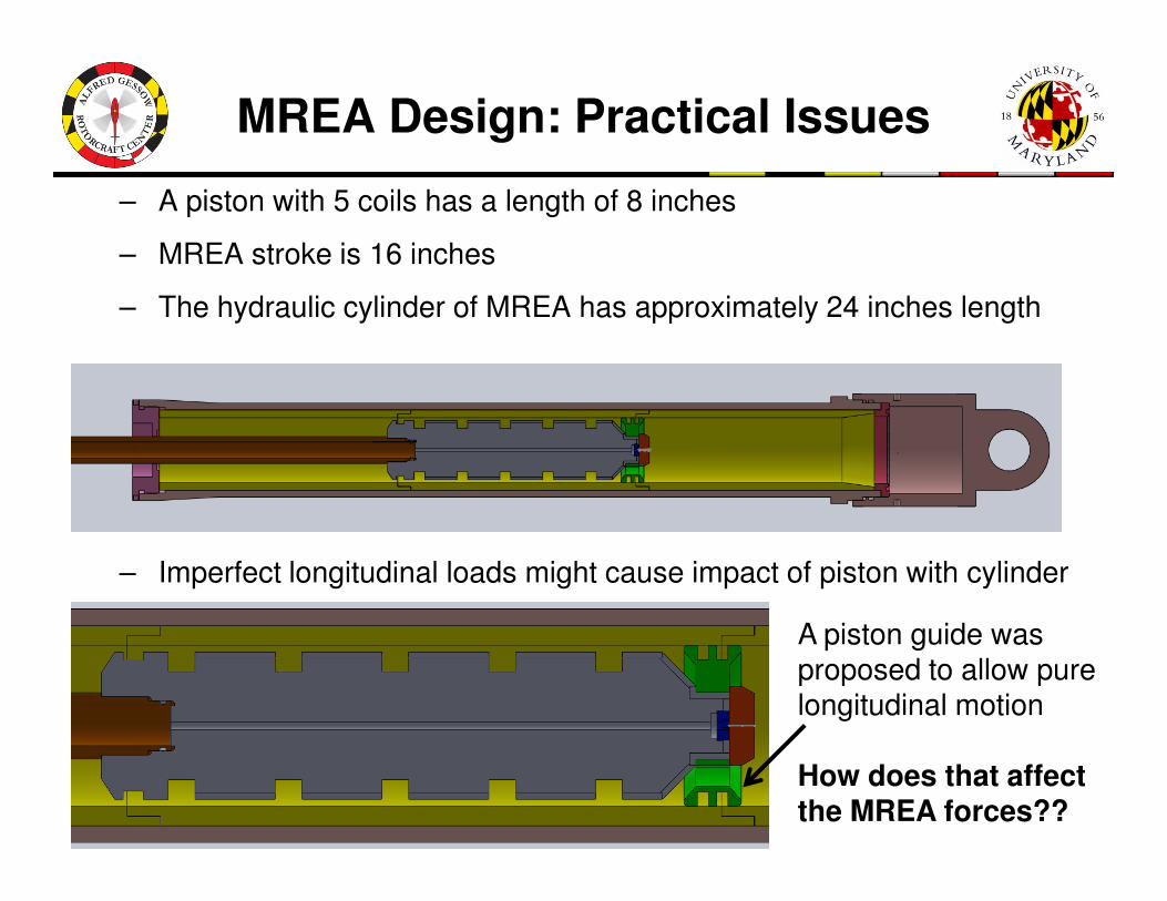
MREA Design: Practical Issues
– A piston with 5 coils has a length of 8 inches
– MREA stroke is 16 inches
– The hydraulic cylinder of MREA has approximately 24 inches length
– Imperfect longitudinal loads might cause impact of piston with cylinder
A piston guide wasproposed to allow purelongitudinal motion
How does that affectthe MREA forces??
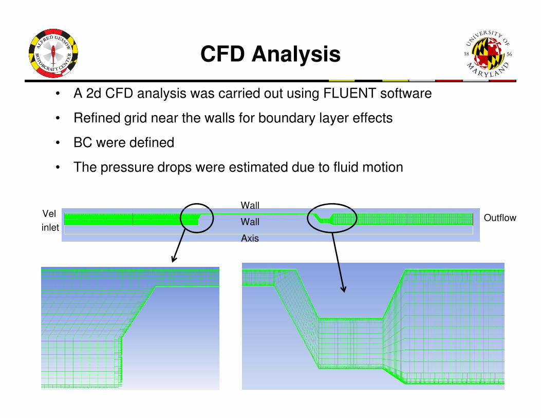
CFD Analysis
• A 2d CFD analysis was carried out using FLUENT software
• Refined grid near the walls for boundary layer effects
• BC were defined
• The pressure drops were estimated due to fluid motion
VelWall
Vel
inletAxis
Wall
OutflowWall

CFD Analysis
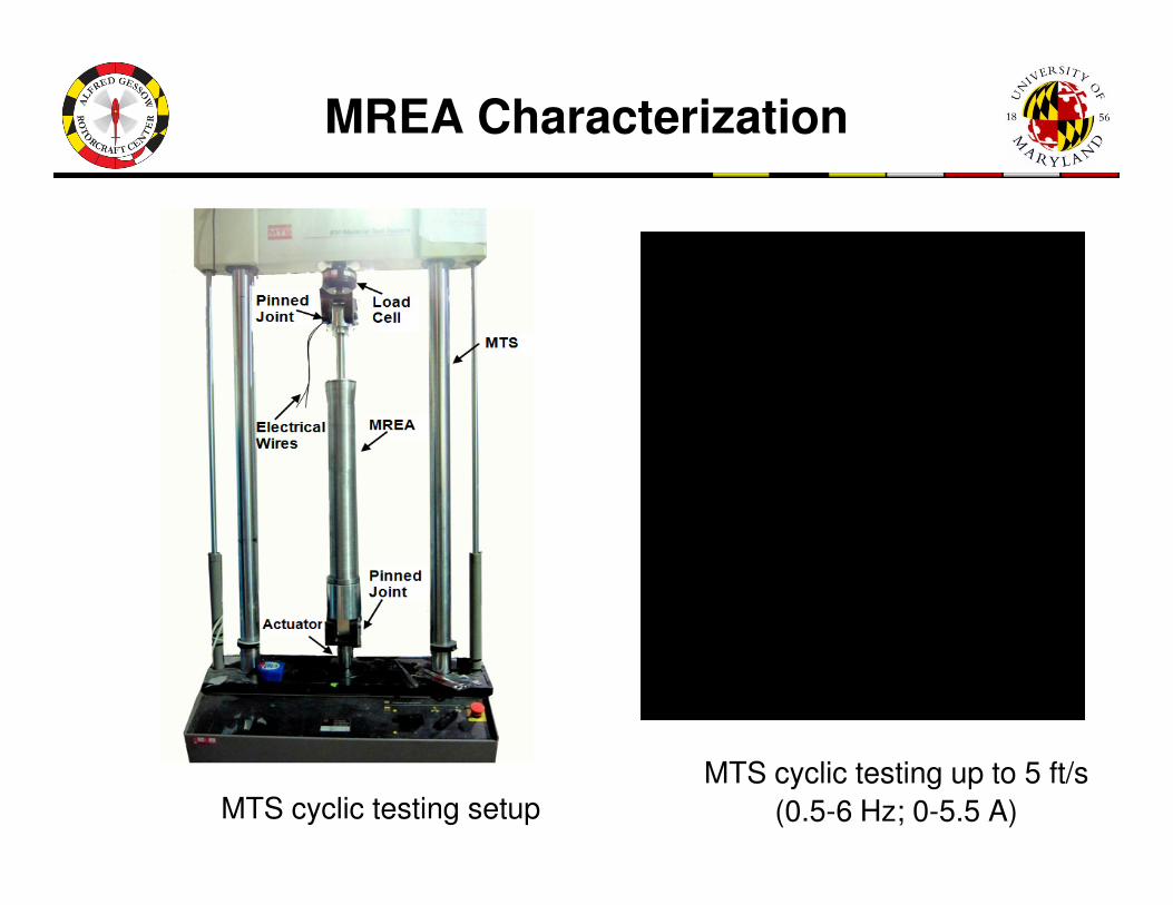
MREA Characterization
MTS cyclic testing up to 5 ft/s
(0.5-6 Hz; 0-5.5 A) MTS cyclic testing setup

Drop Tests
Drop tests
up to 15 ft/s (Field off only, 0A)
Drop standDrop test setup
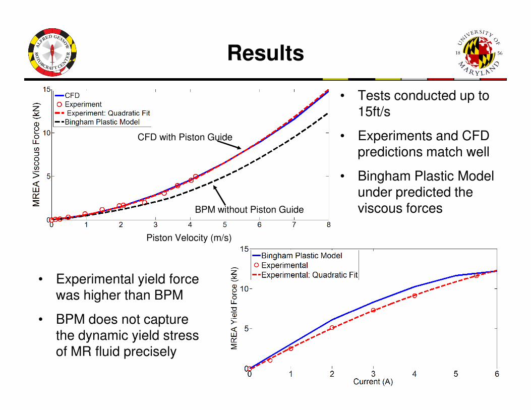
Results
• Tests conducted up to 15ft/s
• Experiments and CFD predictions match well
• Bingham Plastic Model under predicted the viscous forcesBPM without Piston Guide
CFD with Piston Guide
viscous forces
• Experimental yield force was higher than BPM
• BPM does not capture the dynamic yield stress of MR fluid precisely
Piston Velocity (m/s)
BPM without Piston Guide

Outline
Design and Testing of Magnetorheological Energy Absorber
Control Algorithms
– Constant Stroking Load Control
– Terminal Trajectory Control
ConclusionsConclusions

Existing Constant Stroking Load Concepts
• Inversion tubes
• Wire bending
• Cutting and Slitting
Desjardins, S.P., “The Evolution of Energy Absorption Systems for Crashworthy Helicopter Seats,” 59th AHS
Annual Forum, Phoenix, AZ, 6-8 May, 2003
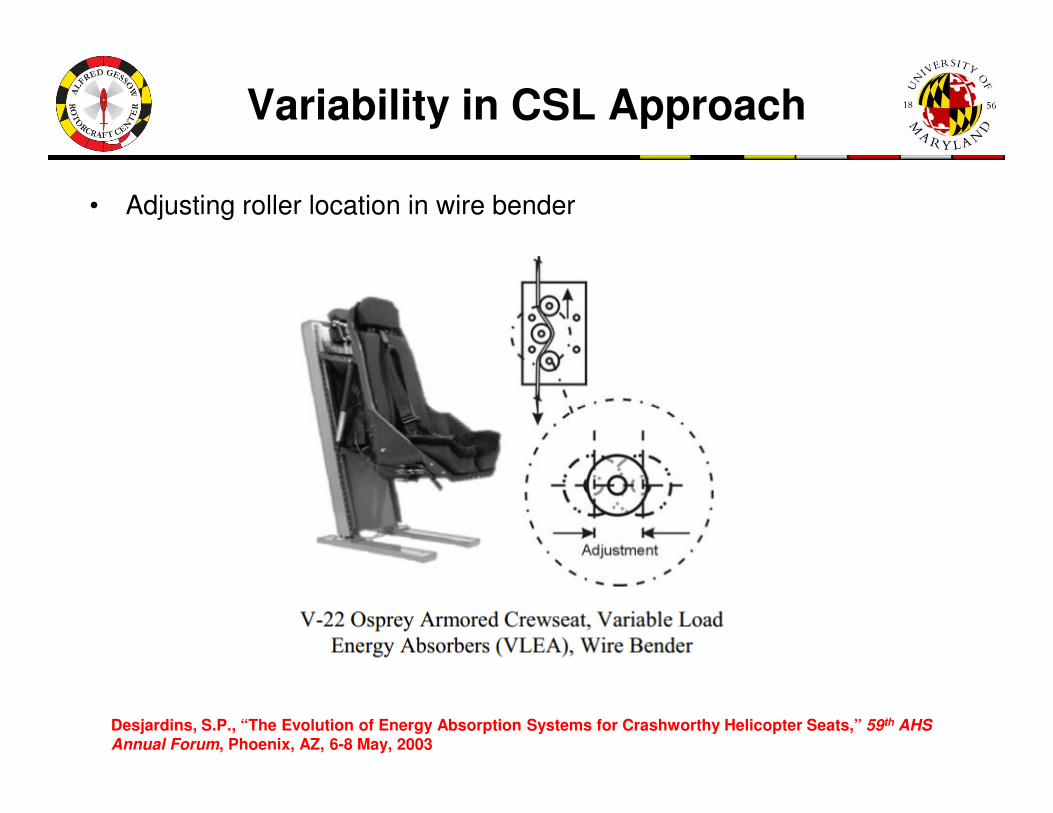
Variability in CSL Approach
• Adjusting roller location in wire bender
Desjardins, S.P., “The Evolution of Energy Absorption Systems for Crashworthy Helicopter Seats,” 59th AHS
Annual Forum, Phoenix, AZ, 6-8 May, 2003

Constant Stroking Load Control
• Stroking the seat based on dynamic limit load of energy absorber.
• Dynamic limit load is the maximum permissible stroking load to whichan occupant can be subjected
• The limit load was found to be: 11.70 kN (14.5Mg); 8.07 kN (10Mg)
• No control authority over passive viscous force
Desjardins, S.P., Zimmerman, R.E., Bolukbasi, A.O., and Merritt, N.A., “Aircraft Crash Survival Design Guide,”Aviation Applied Technology Directorate, USAAVSCOM TR 89-D-22D, Fort Eustis, VA, 1989.

Velocity Feedback

Velocity Feedback
Large oscillations
Test conditionMass: 380 lb (172 kg) Height: 35 in (88.9 cm)
Stroke limit: 7 in
Stroke utilized: 6.1 in
Peak velocity: 2.7 m/s
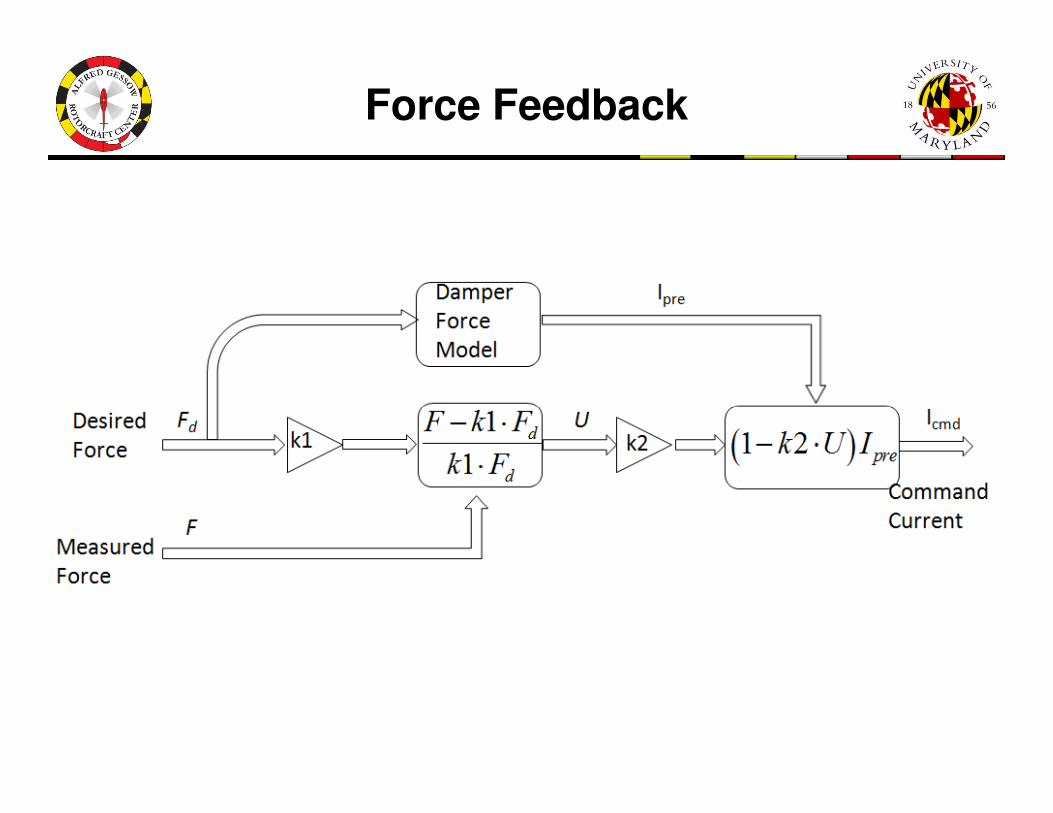
Force Feedback

Force Feedback
Less oscillations
Test conditionMass: 380 lb (172 kg) Height: 35 in (88.9 cm) ; 60 in (152.4 cm)
Stroke Limit: 7 in
Stroke: 2.2 and 4.1 in
Peak velocity: 2.3 and 3.4 m/s
Higher current drop for 60in
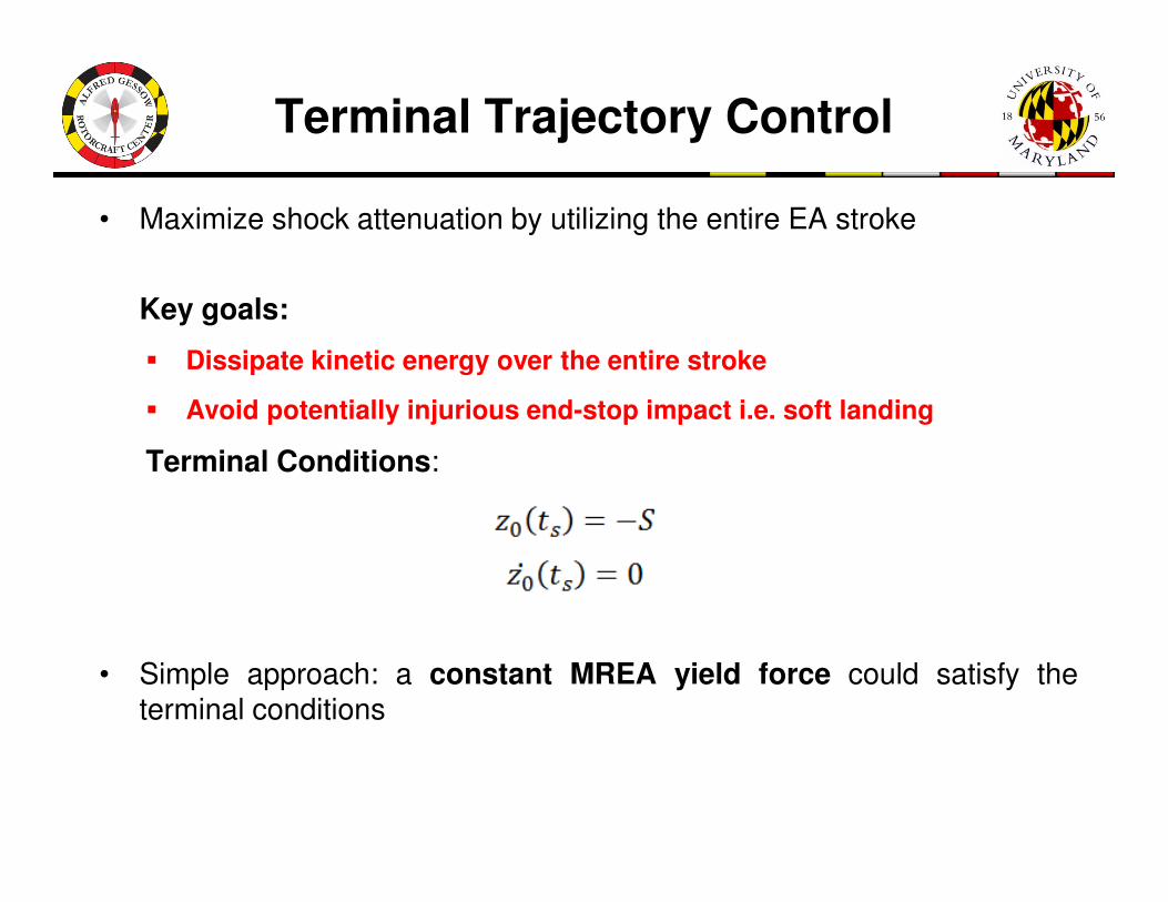
Terminal Trajectory Control
• Maximize shock attenuation by utilizing the entire EA stroke
Key goals:
� Dissipate kinetic energy over the entire stroke
� Avoid potentially injurious end-stop impact i.e. soft landing
Terminal Conditions:Terminal Conditions:
• Simple approach: a constant MREA yield force could satisfy theterminal conditions

Current Estimation
• Modeling the shock as an initial velocity impact
Rigid Payload
H is the drop height; fs due to friction in system
Energy dissipated by honeycombEnergy dissipated by honeycomb
P is crushable stress of honeycomb, h is crushed height.
Energy dissipated by MREA
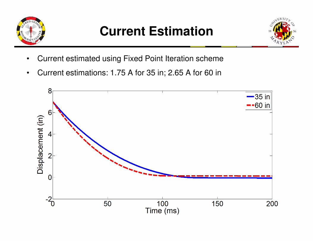
Current Estimation
• Current estimated using Fixed Point Iteration scheme
• Current estimations: 1.75 A for 35 in; 2.65 A for 60 in

Terminal Trajectory Control
Force increased with shock intensity
Test conditionMass: 380 lb (172 kg) Height: 35 in (88.9 cm) ; 60 in (152.4 cm)
Stroke Limit: 7 in
Higher constant current for 60in
Stroke: 6.2 and 6.1 in
Peak velocity: 3.0 and 3.5 m/s

Outline
Design and Testing of Magnetorheological Energy Absorber
Control Algorithms
– Constant Stroking Load Control
– Terminal Trajectory Control
ConclusionsConclusions

Conclusions
• MREA was designed for a large dynamic range or control authority
• MREA performance was evaluated using MTS cycling and drop tests for current inputs of 0-5.5A and speeds up to 15ft/s or 4.5m/s
• Constant stroking load and terminal trajectory control were analyzed
• Velocity feedback based CSLC could not maintain constant load due to strong dependence on velocitystrong dependence on velocity
• Force feedback based CLSC was relatively better
• TTC had no issue of time delay between current and magnetic field buildup
• CLSC – (Existing wire benders, crushable tubes)
Same stroking load Different stroke utilization Poor Adaptation
• TTC performs superior
Adaptive Stroking load Same stroke utilization Good Adaptation

Acknowledgement
The authors acknowledge support for this research
under a contract from The U.S. Naval Air Warfare
Center at Patuxent River, MD (Mr. William Glass as
Technical Monitor)
The authors are thankful to Dr. Joseph Pellettiere forThe authors are thankful to Dr. Joseph Pellettiere for
invitation to 7th Fire and Cabin Safety Conference.
Thank You&
Questions?