control of nasa’s space launch system of nasa’s space launch system ... available design space...
TRANSCRIPT
Success Stories in Control
Control of NASA’s Space Launch System
Challenges of Controlling the Space Launch SystemLike with all large launch vehicles, the SLS control system must balance the competing needs of maximizing performance while maintaining robustness to limitations in pre-flight models . With its high thrust, large size, and multi-structure load paths, SLS exhibits a high degree of structural flexion with non-planar characteristics. Control commands are allocated to each of its six engines which are gimbaled along orthogonal axes by hydraulic thrust vector control actuators, leading to a control resource management challenge. The massive core propellant tanks and long moment arm upper stage tanks have lightly damped lateral sloshing modes. The SLS trajectories are highly optimized to maximize payload-to-orbit performance. These challenges restrict the available design space for the flight control system and leave very little margin to share among the disciplines and subsystems.
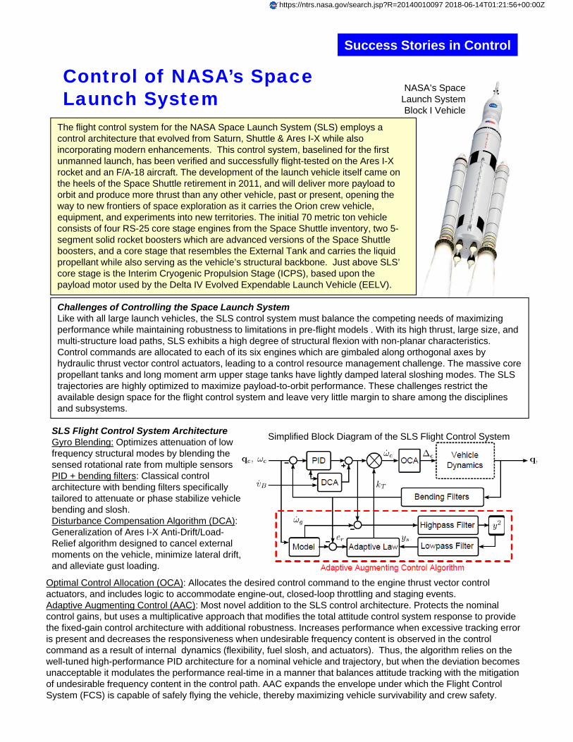
NASA’s Space Launch System Block I Vehicle
The flight control system for the NASA Space Launch System (SLS) employs a control architecture that evolved from Saturn, Shuttle & Ares I-X while also incorporating modern enhancements. This control system, baselined for the first unmanned launch, has been verified and successfully flight-tested on the Ares I-X rocket and an F/A-18 aircraft. The development of the launch vehicle itself came on the heels of the Space Shuttle retirement in 2011, and will deliver more payload to orbit and produce more thrust than any other vehicle, past or present, opening the way to new frontiers of space exploration as it carries the Orion crew vehicle, equipment, and experiments into new territories. The initial 70 metric ton vehicle consists of four RS-25 core stage engines from the Space Shuttle inventory, two 5-segment solid rocket boosters which are advanced versions of the Space Shuttle boosters, and a core stage that resembles the External Tank and carries the liquid propellant while also serving as the vehicle’s structural backbone. Just above SLS’ core stage is the Interim Cryogenic Propulsion Stage (ICPS), based upon the payload motor used by the Delta IV Evolved Expendable Launch Vehicle (EELV).
Optimal Control Allocation (OCA): Allocates the desired control command to the engine thrust vector control actuators, and includes logic to accommodate engine-out, closed-loop throttling and staging events. Adaptive Augmenting Control (AAC): Most novel addition to the SLS control architecture. Protects the nominal control gains, but uses a multiplicative approach that modifies the total attitude control system response to provide the fixed-gain control architecture with additional robustness. Increases performance when excessive tracking error is present and decreases the responsiveness when undesirable frequency content is observed in the control command as a result of internal dynamics (flexibility, fuel slosh, and actuators). Thus, the algorithm relies on the well-tuned high-performance PID architecture for a nominal vehicle and trajectory, but when the deviation becomes unacceptable it modulates the performance real-time in a manner that balances attitude tracking with the mitigation of undesirable frequency content in the control path. AAC expands the envelope under which the Flight Control System (FCS) is capable of safely flying the vehicle, thereby maximizing vehicle survivability and crew safety.
SLS Flight Control System ArchitectureGyro Blending: Optimizes attenuation of low frequency structural modes by blending the sensed rotational rate from multiple sensorsPID + bending filters: Classical control architecture with bending filters specifically tailored to attenuate or phase stabilize vehicle bending and slosh.Disturbance Compensation Algorithm (DCA): Generalization of Ares I-X Anti-Drift/Load-Relief algorithm designed to cancel external moments on the vehicle, minimize lateral drift, and alleviate gust loading.
Simplified Block Diagram of the SLS Flight Control System
https://ntrs.nasa.gov/search.jsp?R=20140010097 2018-06-14T01:21:56+00:00Z

Success Stories in Control
SLS Adaptive Augmenting Control and Flight Testing
Contributor: Tannen S. VanZwieten, NASA Marshall Space Flight Center ([email protected]).For further information:- J. Brandon, S. Derry, E. Heim, R. Hueschen, and B. Bacon, “Ares-I-X Stability and Control Flight Test: Analysis and Plans,” AIAA 2008-7807- J. Orr, J. Wall, T. VanZwieten, and C. Hall, “Space Launch System Ascent Flight Control Design,” AAS 14-038.- J. Orr and T. VanZwieten “Robust, Practical Adaptive Control for Launch Vehicles,” AIAA-2012-4549.- J. Wall, J. Orr, and T. VanZwieten, “Space Launch System Implementation of Adaptive Augmenting Control,” AAS 14-051.- T. VanZwieten et. al., “Adaptive Augmenting Control Flight Characterization Experiment on an F/A-18,” AAS 14-052.
Ares I-X Flight Test Launch (Oct. 28, 2009)
Photographs Depicting the Trajectory Flown Repeatedly by NASA’s F/A-18 while Testing the SLS AAC (2013)
Flight TestingA majority of the components of the SLS Ascent FCS were flown on Ares I-X: sensor blending, PID, bending filters, DCA, and parameter identification maneuvers. A series of F/A-18 research flights were used to test SLS prototype software, including the previously untested AAC and OCA components. The control parameters for this test were identical to the SLS design set, except for disabling the DCA. The fighter aircraft completed a series of trajectories during multiple sorties with the SLS FCS enabled while matching the aircraft’s pitch rate to that of the SLS and matching attitude errors for various nominal and extreme SLS scenarios through the use of a nonlinear dynamic inversion controller. The emphasis of the 100+ SLS-like trajectories was on fully verifying and developing confidence in the adaptive augmenting control algorithm in preparation for the first unmanned launch of SLS.
AAC Design Philosophy
Infusion of Advanced Technology: The Adaptive Augmenting Control AlgorithmIn the absence of vehicle or environmental uncertainty, a fixed-gain controller could be optimized prior to flight such that there would be no motivation for adaptation. However, a review of historical launch vehicle data from 1990 to 2002 revealed that 41% of failures as a result of other malfunctions might have been mitigated by advanced GN&C technologies. Traditional barriers to capitalizing on the benefits of advanced control techniques that are particularly relevant for human-rated systems include algorithm and code complexity, predictability of the response, ability to reconcile the stability analysis in the context of classical gain and phase margin, and flight certification. Thus, an algorithmically simple, predictable adaptive augmenting control design with direct ties to classical stability margins was implemented for SLS. It was initially formulated and tested during the Constellation Program, then refined as part of the baseline autopilot design and flight software prototype for NASA’s Space Launch System (SLS) and flight tested on an F/A-18.
NASA F/A-18 Research Flight Partners: MSFC (SLS), AFRC, NESC, STMD-GCT