control of flow separation using adaptive airfoils m.s. … · · 2013-08-30by 400% was tested...
TRANSCRIPT
Control of Flow Separation Using Adaptive Airfoils
M.S. Chandrasekhara 1
Navy-NASA Joint Institute of Aeronautics
Department of Aeronautics and Astronautics
Naval Postgraduate School, Monterey, CA 93943
M.C. Wilder 2
Navy-NASA Joint Institute of Aeronautics and
MCAT Institute, San Jose, CA
and
L.W. Carr 3
Aeroflightdynamics Directorate, Aviation Research, Development and
Engineering Center, U.S.Army ATCOM and,
Fluid Mechanics Laboratory Branch
NASA Ames Research Center, Moffett Field, CA 94035-1000
ABSTRACT
Submitted to the AIAA 35 th Aerospace Sciences Meeting
January 6-9, 1997, Reno, NV
1. Summary
A novel way of controlling flow separation is reported. The approach involves using an
adaptive airfoil geometry that changes its leading edge shape to adjust to the instantaneous
flow at high angles of attack such that the flow over it remains attached. In particular, a
baseline NACA 0012 airfoil, whose leading edge curvature could be changed dynamically
by 400% was tested under quasi-steady compressible flow conditions. A mechanical drive
system was used to produce a rounded leading edge to reduce the strong local flow accel-
eration around its nose and thus reduce the strong adverse pressure gradient that follows
such a rapid acceleration. Tests in steady flow showed that at M = 0.3, the flow separated
at about 14 deg. angle of attack for the NACA 0012 profile but could be kept attached up
to an angle of about 18 deg by changing the nose curvature. No significant hysteresis effects
1 Associate Director and Research Professor, Assoc. Fellow AIAA,
Mailing Address: M.S. 260-1, NASA Ames Research Center, Moffett Field, CA 94035
Research Scientist
a Research Scientist and Group Leader, Unsteady Viscous Flows, Member AIAA
https://ntrs.nasa.gov/search.jsp?R=20020039533 2018-06-24T11:40:12+00:00Z
were observed; the flow could be made to reattach from its separatedstate at high angles
by changing the leading edgecurvature. Interestingly, the flow over a nearly semicircular
nosedairfoil was separatedevenat low angles. By finding a "window" of anglesof attack
and airfoil profiles, it appearedpossible to keep the flow attached through a maneuver.
The shapechangealso modified the multiple shocks that form over the NACA 0012 airfoil
at M = 0.45. Tests are underway to document the dynamic stall flow control that can be
effected with the change of airfoil geometry using high-speed, real-time, phase-locked, in-
terferometry. Detailed results from these tests are expected to be available for presentation
at the meeting.
2. Introduction
It is well known that performance of aircraft and their components is severely restricted
by the occurrence of flow separation. It is necessary to control and manage flow separation
over airfoils and wings when sustained high lift conditions are expected. The problem
is even more important in unsteady flows such as encountered over the retreating blade
of a helicopter rotor, a pitching aircraft wing or a wing subjected to gust loads. This
task becomes more complicated when these flows are to be controlled in the compressible
regime. Ongoing research 1'_ on compressibility effects on dynamic stall has shown that stall
onset arises during the bursting of a separation bubble (from the strong adverse pressure
gradient that develops downstream of the suction peak) or at higher Mach numbers, from
separation induced by shocks that form over the airfoil. Extremely rapid flow acceleration
is another attribute of the dynamic stall flow, which leads to onset of compressibility effects
at freestream Mach numbers as low as 0.2 causing premature onset of stall. Thus, it is
necessary to reduce the leading edge flow acceleration and the subsequent development of
the adverse pressure gradient if effective flow control has to be achieved. The published
literature 3,4 on separation control describes many novel ideas such as blowing or suction,
use of slats and slots etc. However, their effectiveness in compressible flows is not yet well
established. This prompted the development of the present approach wherein the airfoil
leading edge is deformed to adapt to the instantaneous flow conditions in such a way that
the flow over it remains attached throughout the range of angles of attack of interest. As a
first test in proving the concept and use of a deforming airfoil for flow control, steady flow
separation control was attempted. These studies showed that many different flow regimes
can result as a consequence. This paper describes some of the first results of this effort.
3. Description of the Experiment
3.1. Dynamically Deforming Airfoil Leading Edge Design
The dynamically deforming leading edge (DDLE) airfoil is a 6 in. chord section made
in two parts. The first 25% is made from a custom cast, carbon-fiber composite material,
built up in several laminations. Its thickness increases progressively from the leading edge
where it is about 0.0002 in. thick. The rear 75% of the airfoil is machined from solid
metal, and the leading edge is attached to the rear section by fasteners. The carbon-fiber
skin is attached to a mandrel shaped to a NACA 0012 profile by a tang cast along with the
leading edge. The mandrel, housed inside the airfoil leading edge section is connected by
pins at the airfoil quarter-chord-point to two a.c. brushless servomotors that are computer
driven to push or pull the airfoil leading edge and produce the required shape change. The
whole mechanism has been designed for controlling two-dimensional compressible dynamic
stall of an oscillating airfoil at M = 0.45, and the motors can exert the necessary axial force
(torque) to drive the mandrel at rates of up to 20 Hz to deform the airfoil from its fully
extended NACA 0012 shape to a rounded nose in less than 20 millisec, and return to the
NACA 0012 shape within one pitch oscillation cycle of the airfoil. Encoders mounted on
the motors provide exact position information of the mandrel and thus the leading edge.
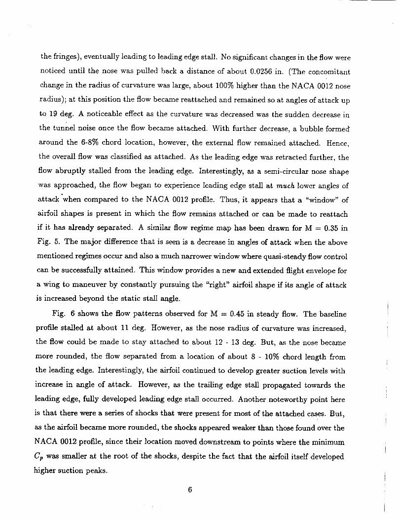
The entire assembly is mounted between two circular windows with L-shaped optical glass
inserts for tests in the compressible dynamic stall facility at NASA Ames Research Center
(CDSF) as is schematically shown in Fig. 1. The details of the facility can be found
in Ref. 5. Fig. 2 shows the range of shape changes and leading curvature that can be
obtained from this design. Bench tests were conducted to ensure that the deformation is
two-dimensional all along the span of the DDLE. This is very important especially since
3

other methods of producing a DDLE yielded strongly three-dimensional shape changes
which are not acceptablefor the present purpose(Ref. 6).
3.2. Details of the Experiments
These first experiments were carried out in steady flow to prove the concept that
a separated flow could be made to reattach by dynamically deforming an airfoil leading
edge. The Mach number of the experimentsranged from 0.3 to 0.45 in increments of 0.05.
The angle of attack wasvaried from 6 degto 20deg, with emphasisover the range where
the flow was initially separated. The measurementtechnique used was point diffraction
interferometry(PDI), which has been describedin Ref. 1 and 2 in detail. The control of
the brushlessmotors providesa way to hold the airfoil leading edgeat any desiredposition
(i.e. curvature) in order to completely document the flow using PDI during a sweepover
a range of anglesof attack. Alternatively, the airfoil angleof attack could be set at a fixed
value and the leading edgecurvature varied. (The controls alsopermit deforming the airfoil
while it is oscillating from a fixed angleof attack at specified rates. TbAslatter option will
be exercisedin the dynamic stall tests that areabout to begin.) PDI imageswereobtained
for each airfoil position and angle of attack. Thesewere analyzed to determine whether
the flow wasseparatedand also to categorizethe type of stall that occurred over the airfoil
in order to assessthe performance of the instantaneousairfoil shape.
In what follows, the results of this preliminary analysis will be described. A full
analysisand somerecommendationsof the desiredshapesat variousanglesof attack where
the flow is otherwise stalled will be presentedat the conference. It is also expected that
some dynamic stall control results will also be available which will be included at that
time.
4. Results and Discussion
4_1.Qualitative Description of Flow at M = 0.3
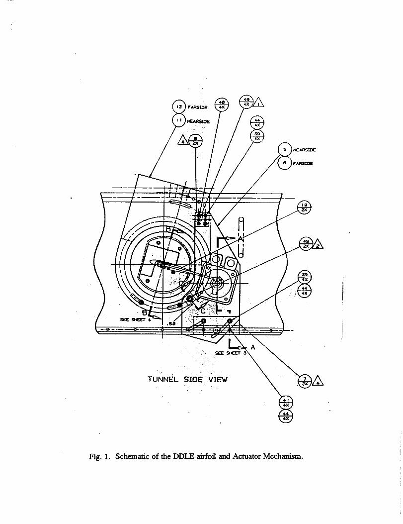
Fig. 3 presentsfour interferogram imagesat M = 0.3 for an angleof attack of 18 deg.
The first image is for the NACA 0012shape (fully extended leading edge of the DDLE
model). Earlier studies7 have shown that the NACA 0012 airfoil experiencesleading edge
stall at 14 deg; the flow has remained separated at 18 deg as well. The second image
in the figure - obtained when the leading edgehas been retracted by 0.0128in. shows
the flow to be fully attached (since the density contours are following the airfoil noseand
turn smoothly parallel to the surface, like streamlines in attached flows). These contours
indicate that the flow has reattached over the airfoil. This is also evidenced by the large
number of fringes near the leading edgewhich points to the re-production of a largesuction
peak oncethe flow reattaches. In the third image, corresponding to a leading edgeposition
of 0.0256in. from the baseline leading edgeof the fringes over the airfoil have flattened
out with thoseon the downstream sidelifting-off the surface. But, since the suction fringes
still follow the "normal" pattern, the flow at this condition is experiencing a mixed-stall
behavior with possible trailing edge separation creeping towards the leading edge and
initiating stall. The last frame in this figure clearly shows leading edgestall again asthe
shear layer has separated from the airfoil nose. The airfoil radius of curvature at this
condition is large and it is nearly semi-circular. These images demonstrate the range of
flow regimes possible at this high angle of attack. Similar pictures were obtained at other
angles of attack and Math numbers.
4.2. Airfoil Performance at Different Leading Edge Curvatures
The flow over the airfoil at different angles and leading edge shapes is summarized in
Fig. 4 as a plot of the various flow regimes that appeared in the experiments at M = 0.3.
It is clear that the flow is attached at low angles for all shapes (in the shaded area). Static
stall occurred at 14 deg for the NACA 0012 profile, beyond which trailing edge stall first
started accompanied by a gradual loss of the suction peak (as measured by a counting of
/
the fringes), eventually leading to leading edge stall. No significant changes in the flow were
noticed until the nose was pulled back a distance of about 0.0256 in. (The concomitant
change in the radius of curvature was large, about 100% higher than the NACA 0012 nose
radius); at this position the flow became reattached and remained so at angles of attack up
to 19 deg. A noticeable effect as the curvature was decreased was the sudden decrease in
the tunnel noise once the flow became attached. With further decrease, a bubble formed
around the 6-8% chord location, however, the external flow remained attached. Hence,
the overall flow was classified as attached. As the leading edge was retracted further, the
flow abruptly stalled from the leading edge. Interestingly, as a semi-circular nose shape
was approached, the flow began to experience leading edge stall at much lower angles of
attack "when compared to the NACA 0019. profile. Thus, it appears that a "window" of
airfoil shapes is present in which the flow remains attached or can be made to reattach
if it has already separated. A similar flow regime map has been drawn for M = 0.35 in
Fig. 5. The major difference that is seen is a decrease in angles of attack when the above
mentioned regimes occur and also a much narrower window where quasi-steady flow control
can be successfully attained. This window provides a new and extended flight envelope for
a wing to maneuver by constantly pursuing the "right" airfoil shape if its angle of attack
is increased beyond the static stall angle.
Fig. 6 shows the flow patterns observed for M = 0.45 in steady flow. The baseline
profile stalled at about 11 deg. However, as the nose radius of curvature was increased,
the flow could be made to stay attached to about 12 - 13 deg. But, as the nose became
more rounded, the flow separated from a location of about 8 - 10% chord length from
the leading edge. Interestingly, the airfoil continued to develop greater suction levels with
increase in angle of attack. However, as the trailing edge stall propagated towards the
leading edge, fully developed leading edge stall occurred. Another noteworthy point here
is that there were a series of shocks that were present for most of the attached cases. But,
as the airfoil became more rounded, the shocks appeared weaker than those found over the
NACA 0012 profile, since their location moved downstream to points where the minimum
Cp was smaller at the root of the shocks, despite the fact that the airfoil itself developed
higher suction peaks.
6

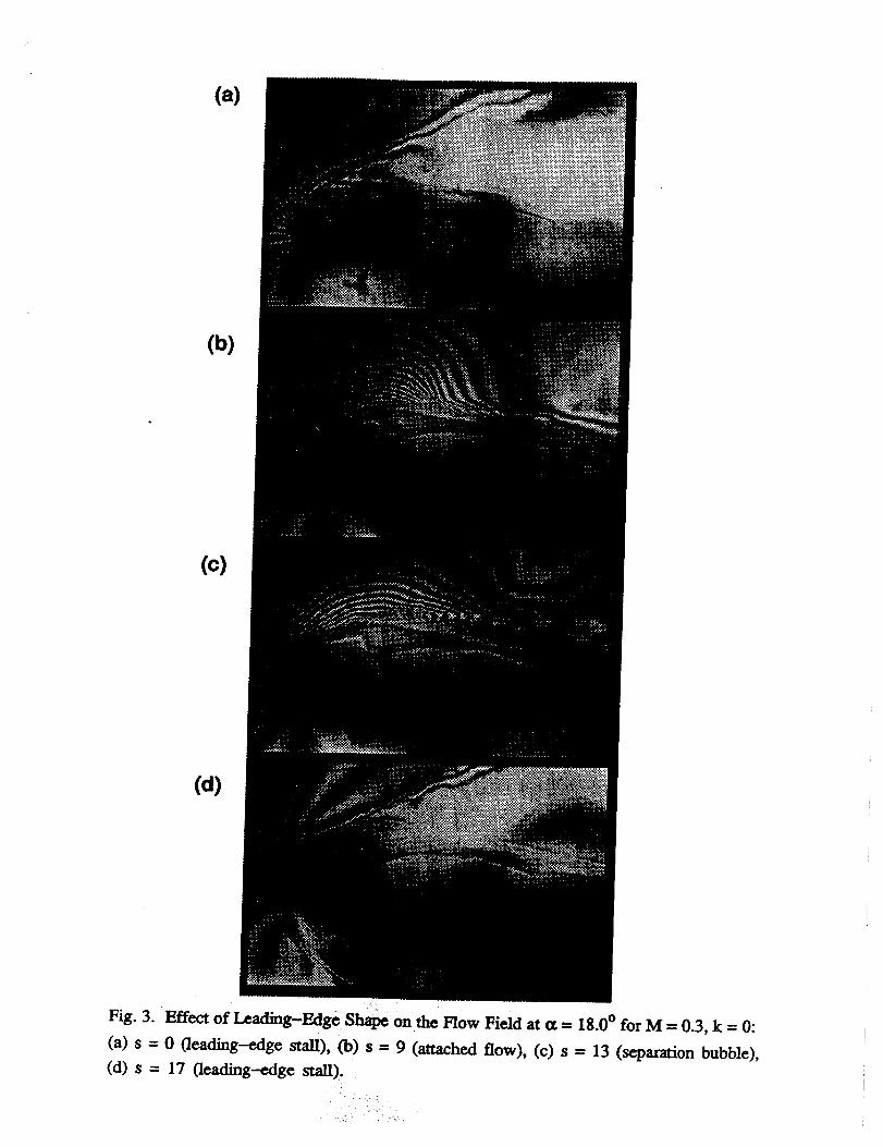
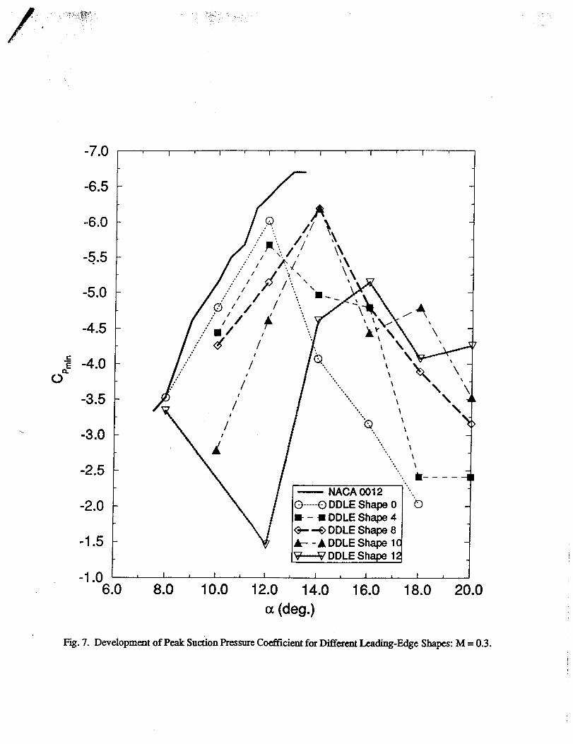
4.3. Developmentof Suction Peak for Different Shapes
Fig. 7 presentsthe developmentof peak suction at M = 0.3 for someof the different
leading edge radii that were created during the tests. The numbers indicated on the graph
correspond to the progressively increasing nose radius when compared to the NACA 0012
profile. It is clear that all profiles with the exception of shape 12 behave in the manner
expected with the peak suction increasing with increasing angle of attack. It also shows
that the NACA 0012 profile developed slightly higher suction levels. However, when this
figure is interpreted in conjunction with Fig. 4 for M = 0.3, it seems that by carefully
shaping the airfoil from the baseline profile to shape 10 for angles of attack from 14 - 18
deg, tile airfoil can be steadily made to produce lift with no increase in drag since the flow
is attached and thus, the deforming airfoil concept is successfully demonstrated. From
such a parametric study, an "optimal" shape history can be generated and used as the
different flight conditions warrant.
A more detailed analysis of the large number of interferograms that were obtained
during the study is ongoing. These results and some unsteady flow results which are
expected to be available soon will be included in the full length paper.
5. Conclusions
A novel concept for separation flow control using dynamically deforming airfoils has
been demonstrated in steady compressible flows. The results presently available show that
attached flow can be maintained up to about 18 deg at M = 0.3 by suitably deforming
the airfoil. Parametric testing has revealed that an optimal shape history can be devised
for such airfoils to sustain attached flow over a range of flow conditions. Control seems
possible at M = 0.45 even when shocks that form locally influence the flow considerably.
References
1Carr, L.W., Chandrasekhara, M.S. and Brock, N., "A Quantitative Study of Un-
steady Compressible Flow on an Oscillating Airfoil", Journal of Aircraft, Vol. 31, No. 4,
7

Jul. - Aug. 1994,pp. 892 - 898.
2Chandrasekhara, M.S., and Carr, L.W., "Compressibility Effects on Dynamic Stall
of Oscillating Airfoils", AGARD-CP-552, Aug. 1995, pp. 3.1 - 3.15.
3Alrefai, M. and Acharya, M., "Controlled Leading-Edge Suction for the Management
of Unsteady Separation over Pitching Airfoils", AIAA Paper 95-2188, Jun. 1995
4Carr, L.W. and McAlister, K.W., "The Effect of a Leading-Edge Slat on the Dynamic
Stall of an Oscillating Airfoil", AIAA Paper 83-3583, Oct. 1983.
5Carr, L.W., and Chandrasekhara, M.S., "Design and Development of a Compressible
Dynamic Stall Facility", Journal of Aircraft, Vol. 29, No. 3, pp. 314-318.
6Wilder, M.C., "Control of Unsteady Separated Flow Associated with the Dynamic
Stall of Airfoils", Final Report 95-09, MCAT Institute, San Jose, CA, Jan. 1995.
7Chandrasekhara, M.S., Wilder, M.C., and Carr, L.W., "Reynolds Number Influence
on 2-D Compressible Dynamic Stall", AIAA Paper 96-0078, Jan. 1996.
TUNNEL
Fig. 1. Schematic of the DDLE airfoil and Actuator Mechanism.

NACA 0012
Semicircular Leading Edge
(fully deformed)
Fig. 2. Sketch Illustrating the Limiting Shapes of the DDLE Surface.
(a)
(b)
(c)
(d)
Fig. 3. Effect of Leading-Edge Shape on the Flow Field at a = 18.0 ° for M = 0.3, k = 0:
(a) s = 0 (leading-edge stall), Co) s = 9 (attached flow), (c) s = 13 (separation bubble),
(d) s = 17 (leading--edge stall).

DDLE Flow Control
M = 0.3, steady flow
18.0
16.0
u 14.0
O
43
12.0
10.0
8.0
Leading
Edge Stall
Leading
Edge Stall
6.0 I I I I0.0 2.0 4.0 6.0 8.0 10.0 12.0 14.0 16.0 18.0
Decreasing LE Sharpness
Fig. 4. Flow regimes for varying angle of attack and leading edge shape: M = 0.3.

DDLE Flow Control
M = 0,35, steady flow
18.0Leading
< 12.0
10.0
6.00.0 2.0 4.0
_'_
N':"i-'-':_"
N1
S
/
• _:w-::_::_i:
_._;..'_:_.-.-..!
_:-:_i_,:::::::::::::::::::::
.,'.":::::_::..::-:::
6.0
Leading
Edge Stall
I I I
8.0 10.0 12.0 14.0 16.0 18.0
Decreasing LE Sharpness
Fig. 5. Flow regimes for varying angle of attack and leading edge shape: M = 0.35.

D DLE Flow Control
M = 0,45, steady flow
U
O
O
18.0
16.0
14.0
12.0
10.0
8.0
_ AttachedFlow
Attached Flowwith Bubble
--_ TrailingEdge Stall
Locally SeparatedFlow with High LE
Suction Pressure
,:",_',_ _ _ ..........................
Edge Stall
6.0 I I I I I I I I0.0 2.0 4.0 6.0 8.0 10.0 12.0 14.0 16.0 18.0
Decreasing LE Sharpness
Fig. 6. Flow regimes for varying angle of attack and leading edge shape: M = 0.45.
-7.0 I ' I ' I ' I ' I _ I '
cE
Q.
0
-6.5
-6.0
-5.5
-5.0
-4.5
-4.0
-3.5
-3.0
-2.5
-2.0
-1.5
//
/#
/I
/I
/!
NACA 0012
@..... E) DDLE Shape 0
• - • DDLE Shape 4
_- --£> DDLE Shape 8• -- - • DDLE Shape 1£
DDLE Shape 1
°
©
-1.0 , I , I , I , I , I , I I
6.0 8.0 10.0 "12.0 14.0 16.0 18.0 20.0
o_(deg.)
Fig. 7. Development of Peak Suction Pressure Coefficient for Different Leading-Edge Shapes: M = 0.3.