control and operation of dc microgrids
TRANSCRIPT

This document is downloaded from DR‑NTU (https://dr.ntu.edu.sg)Nanyang Technological University, Singapore.
Control and operation of DC microgrids
Adhikari, Sujan
2018
Adhikari, S. (2018). Control and operation of DC microgrids. Doctoral thesis, NanyangTechnological University, Singapore.
http://hdl.handle.net/10356/74724
https://doi.org/10.32657/10356/74724
Downloaded on 01 Apr 2022 22:53:53 SGT

Control and Operation of DCMicrogrids
Sujan Adhikari
School of Electrical and ElectronicEngineering
A thesis submitted to the Nanyang Technological Universityin partial fulfillment of the requirement for the degree of
Doctor of Philosophy
2018


Statement of Originality
I hereby certify that the work embodied in this thesis is the result of originalresearch and has not been submitted to higher degree to any other University orInstitution.
I certify that the intellectual content of this thesis is the product of my own workand that all the assistance received in preparing this thesis and sources have beenacknowledged.
Date Sujan Adhikari


To my Grandfather and Grandmother.


Acknowledgement
First of all, I would like to express my deepest gratitude and appreciation to mysupervisor, Professor Dr. Peng Wang for the continuous support to my PhD studyand related research, for his patience, motivation, and immense knowledge. Hisadvices and suggestions have helped to develop my interpersonal, academic andtechnical skills.
A very special gratitude goes to Assistant Professor Dr. Yi Tang for his aspir-ing guidance, invaluable assistance and friendly advice during my PhD journeywithout which this thesis could not be completed. I am very much indebted tohim and thank him for teaching me quality research in power electronics applica-tions. I would also like to thank SINGA scholarship program for providing me thefinancial support to pursue my PhD.
I would like to thank all my friends and laboratory incharge Mr. Tan Peng Chyefrom theWater and Energy Research Laboratory (WERL) for facilitating my needsand providing ample suggestions while I was doing my research work. I am gratefulto all my family members for their support, motivation and encouragement. I amindebted to Dr. Xiaochiang Li, Qi Yang and Ujjal Manandhar for their great helpduring discussions regarding research work. Thanks to Sumit Bam Shrestha, DipuManandhar and Amrit Paudel for their help and support. I thank all my friendsin Nanyang Technological University (NTU) who are always supportive.
I am also grateful to all the university staffs who have helped me during these fouryears and every colleagues in WERL, it was great sharing of laboratory with allof you during last four years.
And finally, last but by no means least, a special thanks to my wife, SamridhiPant. It was not an easy journey. I am grateful for your patience, motivation andstrong support during all these years.
Thanks for all your encouragement!
i


Abstract
The utilization of DC microgrids in power industry has increased rapidly with theexpansion in use of renewable energy sources (RES), energy storages and DC in-herent loads. DC microgrid reduces the power conversion stages, does not requirefrequency, phase and reactive power control in its operation making it advanta-geous over AC microgrids. However, the cost-effective solution to renewable inter-mittency, system topology and standards for reliable, stable and efficient powersupply still needs examinations through research. Control strategies, for economicsolution to mitigate renewable intermittency in the system with inclusion of hy-brid energy storage system (HESS), interconnection of microgrids with tie-line forreliable power supply and bipolar-type DC microgrids for high quality and highefficiency power supply, is proposed, implemented and elaborated in this thesis.
Energy storages are an option to solve renewable intermittency that can increasethe utilization of RES into grid, changing the undispatchable generation to dis-patchable. Energy storages can generate profit upon charging them when localelectricity price lowers and can be discharged when the price is high. Choice ofenergy storage ranging from short term to long term is a key factor to addressthe compensation of load peaks, transients and to provide autonomy to the micro-grids. Unfortunately, they cannot be achieved by a single energy storage, thus theneed of hybridization of energy storages that have high specific energy and specificpower is the solution for proper compensation of power fluctuation in autonomousmicrogrids. Upon review, it was also found that combination of lead-acid batteryand supercapacitor compensate the gap of high energy density and high powerdensity respectively and proved to be the best solution for hybrid energy storageapplications and hence used as HESS in this research.
The conventional droop based decentralized control achieves static power regula-tion however, lacks to address frequency based autonomous power management fordynamic power control. Hence, a frequency coordinating virtual impedance con-cept has been explored in this thesis for the co-ordination control of an HESS inDC microgrids. It investigates power decoupling methods to better attenuate theripple power by filtration. This research uses lead-acid battery and supercapaci-tor to form HESS and are connected to a common DC bus through bi-directionalDC-DC converters. Battery converter can absorb low frequency power variationswhile supercapacitor converter can absorb the high frequency power variations.Battery supplies the long-term power demand and supercapacitor responds to the
iii

Page : iv Abstract
short-term power fluctuations during transient process in this control approach.For the reduction of ripple power in battery, insertion of high order low pass filterfor battery and high order high pass filter for supercapacitor converters insteadof lower order low/high pass filters have been proposed. The effectiveness of theproposed concept is shown through simulation and experimental results.
The interconnection of DC microgrids for providing reliable power supply is par-ticularly important in rural areas where utility grid is not available. Although,various researches are conducted in single entity, the interconnection of DC mi-crogrid cluster is still novice in research. The interconnection of identical DCbuses through tie-line and formation of microgrid clusters improves reliability ofthe system. To achieve power flow control through the tie- line, decentralized con-trol approach has been proposed where the bus voltage of each microgrid in themicrogrid cluster is controlled to ensure the regulation of bus voltage deviations.The use of decentralized control approach mitigates the issue of communicationstress when the microgrid control areas are geographically distantly located. Thedecentralized control is accompanied by mode change based operation so that thedistributed units like solar photovoltaic (PV) and energy storage system (ESS) inmicrogrids can adaptively adjust their operation modes depending upon the desig-nated voltage level. By doing so, the bus voltage regulation (BVR) and power flowcontrol is adjusted making each microgrid in the microgrid cluster autonomous.The power is generated/injected from/into microgrid when there is power sur-plus/deficit caused by supply-demand mismatch in particular microgrid. Tie-linepower flow takes place in a microgrid, from another microgrid, due to the busvoltage decrement beyond the designated level caused by the increment in localconsumption which could not be satisfied by the local generation and storages. Theeffectiveness of proposed decentralized control has been verified experimentally inthe cluster of two microgrids.
Recently, bipolar-type DC microgrids have gained tremendous attention of re-searchers due to its advantages over conventional DC microgrids in terms of el-evated level of quality, reliability and efficient power supply. Due to differentloading in upper and lower terminals, voltage fluctuation from nominal value atrespective terminals takes place and makes the system unbalanced. So, the controlof parallel converters which interface distributed energy resources (DERs) and thetopology of the converter along with voltage balancer play vital role in formationof efficient bipolar-type DC microgrid.
The bipolar configuration of converters in a DC microgrid can be formed by uti-lizing a converter to boost the input voltage and adopting a three-wire system bythe means of voltage balancing circuit. Although many control schemes have beenproposed for bipolar-type DC microgrids, they mainly focus on coupled microgridswith a centralized voltage balancer. The centralized voltage balancing technique isprone to deteriorate the system functionality due to the failure in communicationlinks. Replacement of a centralized proportional-integral controller with multipledecentralized voltage balancers in a microgrid enhances the system reliability byremoval of the communication links. This thesis proposes a decentralized control
Nanyang Technological University Singapore

Abstract Page : v
for bipolar-type DC microgrids with a decentralized voltage balancing scheme fortwo battery energy storages. Droop control is implemented in this thesis for boostconverters and voltage balancing circuits to realize decentralized power manage-ment for both load sharing and voltage balancing. The simulation results andexperimental validations are provided to present the problem and associated so-lutions.
The proposed control strategies for operation of DCmicrogrid incorporating rooftopPV and HESS, interconnection of two DC microgrids consisting of PV and energystorages and bipolar-type DC microgrid consisting of two energy storages havebeen verified with Piecewise linear electrical circuit simulation (PLECS) software.Experimental cases have been carried out to validate the simulation studies withlaboratory scale DC microgrid(s) prototype(s) developed at Water and EnergyResearch Laboratory (WERL), School of Electrical and Electronic Engineering,Nanyang Technological University.
Nanyang Technological University Singapore


Table of Contents
Acknowledgement i
Abstract iii
List of Figures xi
List of Tables xiii
Acronyms and Symbols xv
1 Introduction 11.1 Background . . . . . . . . . . . . . . . . . . . . . . . . . . . . . . . 11.2 Overview of DC microgrids . . . . . . . . . . . . . . . . . . . . . . . 41.3 Obstacles to DC microgrid deployment . . . . . . . . . . . . . . . . 61.4 Objectives . . . . . . . . . . . . . . . . . . . . . . . . . . . . . . . . 81.5 Thesis Contributions . . . . . . . . . . . . . . . . . . . . . . . . . . 91.6 Organization of the Thesis . . . . . . . . . . . . . . . . . . . . . . . 11
2 Configuration and Control of DC microgrids 132.1 Review on Constituents of DC Microgrids . . . . . . . . . . . . . . 14
2.1.1 Solar PV System . . . . . . . . . . . . . . . . . . . . . . . . 142.1.2 Energy Storage System . . . . . . . . . . . . . . . . . . . . . 182.1.3 Hybrid Energy Storage System . . . . . . . . . . . . . . . . 21
2.2 Review on Configuration of DC microgrids . . . . . . . . . . . . . . 252.2.1 Single Bus Topology . . . . . . . . . . . . . . . . . . . . . . 252.2.2 Multibus Topology . . . . . . . . . . . . . . . . . . . . . . . 272.2.3 Reconfigurable Topology . . . . . . . . . . . . . . . . . . . . 27
2.3 Review on Control of DC microgrids . . . . . . . . . . . . . . . . . 292.3.1 Centralized Control . . . . . . . . . . . . . . . . . . . . . . . 302.3.2 Distributed Control . . . . . . . . . . . . . . . . . . . . . . . 322.3.3 Decentralized Control . . . . . . . . . . . . . . . . . . . . . . 35
2.4 Summary . . . . . . . . . . . . . . . . . . . . . . . . . . . . . . . . 43
3 Decentralized Control of DC Microgrids 453.1 Autonomous Droop Control . . . . . . . . . . . . . . . . . . . . . . 463.2 Frequency Co-ordinated Virtual Impedances . . . . . . . . . . . . . 50
vii

Page : viii Table of Contents
3.2.1 Battery/SC Converter Control . . . . . . . . . . . . . . . . . 523.2.2 Supercapacitor Voltage Restoration . . . . . . . . . . . . . . 563.2.3 Simulation and Experimental Verification . . . . . . . . . . . 58
3.3 Summary . . . . . . . . . . . . . . . . . . . . . . . . . . . . . . . . 64
4 Interconnection of DC Microgrids 674.1 Interconnection of DC Microgrids Through Tie-line . . . . . . . . . 694.2 Decentralized Control Strategies . . . . . . . . . . . . . . . . . . . . 72
4.2.1 Autonomous Decentralized Control . . . . . . . . . . . . . . 724.2.2 Mode Adaptive Decentralized Control . . . . . . . . . . . . . 744.2.3 Simulation and Experimental Verification . . . . . . . . . . . 77
4.3 Summary . . . . . . . . . . . . . . . . . . . . . . . . . . . . . . . . 85
5 Bipolar-Type DC Microgrids 875.1 Decentralized Control of Bipolar-Type DC Microgrids . . . . . . . . 915.2 Decentralized Voltage Balancing Control . . . . . . . . . . . . . . . 945.3 Simulation and Experimental Verification . . . . . . . . . . . . . . . 985.4 Summary . . . . . . . . . . . . . . . . . . . . . . . . . . . . . . . . 104
6 Conclusions and Future Work 1056.1 Conclusions . . . . . . . . . . . . . . . . . . . . . . . . . . . . . . . 1056.2 Future Work . . . . . . . . . . . . . . . . . . . . . . . . . . . . . . . 107
A Energy Storage Parameters 109A.1 Vanadium Redox Flow Battery . . . . . . . . . . . . . . . . . . . . 109A.2 Lead-acid Battery . . . . . . . . . . . . . . . . . . . . . . . . . . . . 110A.3 NiCd battery . . . . . . . . . . . . . . . . . . . . . . . . . . . . . . 111A.4 NiMH battery . . . . . . . . . . . . . . . . . . . . . . . . . . . . . . 112A.5 Li-ion battery . . . . . . . . . . . . . . . . . . . . . . . . . . . . . . 113A.6 Supercapacitor . . . . . . . . . . . . . . . . . . . . . . . . . . . . . 114
B Small Signal Modeling of Boost Converter 115
Author’s Publications 119
Bibliography 121
Nanyang Technological University Singapore

List of Figures
1.1 Schematic layout of a generic DC microgrid . . . . . . . . . . . . . 5
2.1 Equivalent circuit of typical PV module (a) Simplest model (b)Sophisticated model . . . . . . . . . . . . . . . . . . . . . . . . . . . 14
2.2 I-V characteristic of solar PV . . . . . . . . . . . . . . . . . . . . . 162.3 Solar PV converter a) Schematic representation of DC-DC boost
converter b) Controller for solar PV converter . . . . . . . . . . . . 172.4 Battery converter a) Schematic layout of bi-directional DC-DC con-
verter b) Controller for battery converter . . . . . . . . . . . . . . 212.5 Schematic layouts of different HESS topologies (a) Passive config-
uration for HESS (b) SC only connected to converter (c) Batteryonly connected to converter (d) Cascaded connection of battery/SCthrough DC-DC converter (e) Parallel connection of battery /SC tothe DC bus . . . . . . . . . . . . . . . . . . . . . . . . . . . . . . . 24
2.6 Schematic layout of an unipolar DC microgrid . . . . . . . . . . . . 252.7 Schematic layout of a bipolar-type DC microgrid . . . . . . . . . . . 262.8 Schematic layout of multibus DC microgrid . . . . . . . . . . . . . 272.9 Schematic layout of a DC microgrid ringbus topology . . . . . . . . 282.10 Schematic layout of a multiterminal DC microgrid . . . . . . . . . . 282.11 Schematic layout of a zonal DC microgrid . . . . . . . . . . . . . . 292.12 Schematic layout of master slave control . . . . . . . . . . . . . . . 312.13 General schematic layout of centralized control . . . . . . . . . . . . 322.14 Schematic layout of distributed control . . . . . . . . . . . . . . . . 332.15 Control diagram proposed by Wang et al. . . . . . . . . . . . . . . . 342.16 Schematic layout of decentralized control . . . . . . . . . . . . . . . 362.17 Equivalent circuit representing DC bus . . . . . . . . . . . . . . . . 362.18 Operation mode classification and DBS principle (a) Utility dom-
inating mode (b) Storage dominating mode (c) Generation domi-nating mode (d) Voltage range definition for mode transition . . . . 38
2.19 Control for ESU in DBS power management . . . . . . . . . . . . . 412.20 Mode switcher for surge current compensation . . . . . . . . . . . . 42
3.1 Thevenin equivalent circuit for one DER . . . . . . . . . . . . . . . 463.2 Conventional droop control for DC microgrids . . . . . . . . . . . . 473.3 Equivalent circuit of two source single load DC microgrid . . . . . . 483.4 Relationship between current sharing and virtual resistance . . . . . 49
ix
Page : x List of Figures
3.5 Control loop for virtual impedance concept with converter . . . . . 523.6 Inner current control loop . . . . . . . . . . . . . . . . . . . . . . . 533.7 Bode plots for open loop current control . . . . . . . . . . . . . . . 533.8 Control loops for Hybrid ESS (a) for battery converter (b) for su-
percapacitor converter . . . . . . . . . . . . . . . . . . . . . . . . . 543.9 Impedance vs frequency for converters with lower order filters . . . 553.10 Impedance vs frequency for converters with higher order filters . . . 553.11 Supercapacitor voltage restoration loop . . . . . . . . . . . . . . . . 563.12 Converter model for modified supercapacitor voltage restoration loop 573.13 Simulation and experimental setup (a) Schematic layout (b) Exper-
imental platform . . . . . . . . . . . . . . . . . . . . . . . . . . . . 583.14 Waveforms for existing control loop during step load change (a)
Step load increase (b) Step load decrease . . . . . . . . . . . . . . . 593.15 Waveforms for proposed control loop during step load change (a)
Step load increase (b) Step load decrease . . . . . . . . . . . . . . . 603.16 Waveforms for existing control loop during change in PV generation 613.17 Change in PV generation for proposed control loop . . . . . . . . . 623.18 FFT of the system (a) using first order filter (b) using second order
filter . . . . . . . . . . . . . . . . . . . . . . . . . . . . . . . . . . . 623.19 Experimental waveforms for existing control loop during step load
change . . . . . . . . . . . . . . . . . . . . . . . . . . . . . . . . . . 633.20 Experimental waveforms with lower-order filters during transient
process . . . . . . . . . . . . . . . . . . . . . . . . . . . . . . . . . . 633.21 Experimental waveforms with higher-order filters during transient
process . . . . . . . . . . . . . . . . . . . . . . . . . . . . . . . . . . 64
4.1 Schematic layout of two DC microgrids interconnected with tie-line 704.2 Model of two interconnected microgrids with decentralized control
loop for bus voltage error minimization . . . . . . . . . . . . . . . . 724.3 Graphical representation of mode adaptive control . . . . . . . . . . 764.4 Performance of proposed decentralized control method . . . . . . . 784.5 Waveforms for DC bus voltages and battery power in MG1 and MG2 794.6 DC bus voltages and tie-line current during mode change . . . . . . 804.7 PV power at MG1 and MG2 during mode change . . . . . . . . . . 804.8 Schematic layout of experimental platform . . . . . . . . . . . . . . 814.9 Step load change in MG2 . . . . . . . . . . . . . . . . . . . . . . . . 814.10 Tie-line current during step load change in MG2 . . . . . . . . . . . 824.11 Sinusoidal fluctuation in PV generation in MG1 . . . . . . . . . . . 834.12 Bus voltages and battery current during sinusoidal fluctuation in
PV generation in MG1 . . . . . . . . . . . . . . . . . . . . . . . . . 834.13 Test for mode change based operation in MG1 . . . . . . . . . . . . 844.14 Examination of tie-line current flow from MG1 to MG2 . . . . . . . 844.15 Bus voltages and battery current during tie-line current flow in MG2 85
5.1 A typical low voltage bipolar-type DC grid . . . . . . . . . . . . . . 895.2 Two cascaded VSC for bipolar output . . . . . . . . . . . . . . . . . 90
Nanyang Technological University Singapore

List of Figures Page : xi
5.3 Single VSC with neutral line current regulation for bipolar output . 905.4 Extra half-bridge circuit for achieving bipolar output . . . . . . . . 915.5 Power circuit for a bipolar DC microgrid with control block diagram 935.6 Voltage and current waveforms to show control conflict . . . . . . . 955.7 Proposed control (a) Voltage balancing circuit (b) V-I droop curve
for voltage balancing circuit . . . . . . . . . . . . . . . . . . . . . . 965.8 Voltage and current waveforms for same droop gain . . . . . . . . . 995.9 Voltage and current waveforms for different droop gains . . . . . . 1005.10 Bus voltages and load current waveforms for same droop gain . . . 1025.11 Inductor currents for boost converters and balancing circuits for
same droop gain . . . . . . . . . . . . . . . . . . . . . . . . . . . . . 1025.12 Bus voltages and load current waveforms for different droop gain . . 1035.13 Inductor currents for boost converters and balancing circuits for
different droop gain . . . . . . . . . . . . . . . . . . . . . . . . . . . 103
B.1 Power circuit of DC-DC boost converter . . . . . . . . . . . . . . . 115B.2 Modes of operation in boost converter (a) when switch Si is ON
(b)when switch Si is OFF . . . . . . . . . . . . . . . . . . . . . . . 116
Nanyang Technological University Singapore


List of Tables
2.1 Solar panel parameters for SPR-305-WHT module . . . . . . . . . . 162.2 Tabulation of parametric comparison of different storage technologies 202.3 Summary of mode transition in DC microgrids . . . . . . . . . . . . 39
3.1 Boost converter parameters . . . . . . . . . . . . . . . . . . . . . . 543.2 Simulation and experimental parameters . . . . . . . . . . . . . . . 58
4.1 Operation modes and corresponding values during different voltagelevels . . . . . . . . . . . . . . . . . . . . . . . . . . . . . . . . . . . 75
4.2 Simulation and experimental parameters . . . . . . . . . . . . . . . 77
5.1 Simulation and experimental parameters . . . . . . . . . . . . . . . 98
A.1 VRB battery parameters . . . . . . . . . . . . . . . . . . . . . . . . 109A.2 Lead-acid battery parameters . . . . . . . . . . . . . . . . . . . . . 110A.3 NiCd battery parameters . . . . . . . . . . . . . . . . . . . . . . . . 111A.4 NiMH battery parameters . . . . . . . . . . . . . . . . . . . . . . . 112A.5 Li-ion battery parameters . . . . . . . . . . . . . . . . . . . . . . . 113A.6 Supercapacitor parameters . . . . . . . . . . . . . . . . . . . . . . . 114
xiii


Acronyms and Symbols
AcronymsAC Alternating Current
BESS Battery Energy Storage System
BIC Bi-directional Interlinking Converter
BMS Battery Management System
BRM Bus Regulating Mode
BVR Bus Voltage Regulation
CAES Compressed Air Energy Storage
CC Charge Controller
CP Constant Power
CV Constant Voltage
DBS DC Bus Signaling
DC Direct Current
DCL Digital Communication Link
DERs Distributed Energy Resources
DGs Distributed Generators
DMS Distribution Management System
DNO Distribution Network Operator
EDLC Electrochemical Double Layer Capacitor
EMS Energy Management System
ESUs Energy Storage Units
ETSI European Telecommunications Standards Institute
FFT Fast Fourier Transform
HESS Hybrid Energy Storage System
xv

Page : xvi Acronyms and Symbols
HPF High Pass Filter
HVDC High Voltage Direct Current
IED Intelligent Electronic Device
IEEE-SA Institute of Electrical and Electronic Engineering Standard As-sociation
KCL Kirchhoff’s Current Law
LBC Low Bandwidth Communication
LCs Local Controllers
LFC Load frequency control
Li-ion Lithium ion
LPF Low Pass Filter
LVDC Low-Voltage DC
MG1 Microgrid 1
MG2 Microgrid 2
MGCCs Microgrid Central Controllers
MPP Maximum Power Point
MPPT Maximum Power Point Tracking
MTDC Multiterminal DC systems
MVAC Medium Voltage AC
NiCd Nickel-Cadmium
NiMH Nickel-Metal Hydride
PCM Power Control Mode
PCS Power Converter System
PI Proportional-Integral
PLECS Piecewise Linear Electrical Circuit Simulation
PLS Power Line Signaling
PM Phase Margin
PR Proportional Resonant
PV Photovoltaic
PWM Pulse Width Modulation
R & D Research and Development
Nanyang Technological University Singapore

Acronyms and Symbols Page : xvii
RES Renewable Energy Sources
SC Supercapacitor
SCESS Supercapacitor Energy Storage System
SEPIC Single-Ended Primary Converter
SMES Superconducting Magnetic Energy Storage
SoC State of Charge
STC Standard Test Condition
UC Ultracapacitor
VDC Voltage Droop Controller
VRB Vanadium Redox flow Battery
VSC Voltage Source Converter
ZEBs Zero-net-Energy Buildings
ZTDC Zonal Type DC
Symbols
ωc Filter crossover-frequency
ωconv Converter frequency
ρ Resistivity of conductive material
εv Maximum allowable DC bus voltage deviation in droop control
A Ideality factor
Ac Cross-sectional area of a conductor
C Capacitor
Cdc DC network capacitor
Cbus1 Bus capacitor for MG1
Cbus2 Bus capacitor for MG2
Ci Bus capacitor for ith boost converter
Csup Supercapacitor value
dbat Duty ratio for the battery converter
Di Diode for ith boost converter
dPV Duty ratio for the PV converter
Nanyang Technological University Singapore

Page : xviii Acronyms and Symbols
e Input voltage of boost converter
Gbat Switching signal for the battery converter
GPV Switching signal for the PV converter
ici Capacitor current of ith boost converter
iLi Inductor current of ith boost converter
ioi Output current of ith boost converter
idc Current injected into the DC network
ifl Full load current of the converter
i∗L Reference inductor current
IL_ba1 Inductor current for a voltage balancing circuit of ESS1
IL_ba2 Inductor current for a voltage balancing circuit of ESS2
IL_bai Inductor current at voltage balancing circuit of ith converter ina bipolar-type DC microgrid
iL_baimax Maximum inductor current at ith voltage balancing circuit of abipolar-type DC microgrid
IL_boost1 Inductor current of the ESS1 in a bipolar-type DC microgrid
IL_boost2 Inductor current of the ESS2 in a bipolar-type DC microgrid
Io1 Positive-half current of the ESS1 in a bipolar-type DC microgrid
I−o1 Negative-half current of the ESS1 in a bipolar-type DCmicrogrid
Io2 Positive-half current of the ESS2 in a bipolar-type DC microgrid
I−o2 Negative-half current of the ESS2 in a bipolar-type DCmicrogrid
Iph Photocurrent
IPV Output current of solar PV
Irr Reverse saturation current at temperature Tr
Isat Saturation current
Isc Short-circuit current
isup Supercapacitor output current
Itie Tie-line current
k Boltzman constant
Ki Temperature coefficient of short circuit current
L Inductor
Nanyang Technological University Singapore

Acronyms and Symbols Page : xix
l Length of conductive material
L_bai Inductor at voltage balancing circuit of ith converter in a bipolar-type DC microgrid
Li Inductor current for ith boost converter
Llinei Line inductance from source to the load bus of the ith converterin a DC microgrid
np Number of solar cells in parallel
ns Number of solar cells in series
Pac Rated power output, determined by power system operator fromthe microgrid to the AC utility grid
Pbat Battery bank output power
PDG Power generation in the microgrid by DERs at MPPT state
PESSchMaximum charging power of ESS units in the microgrid
PESSdchMaximum discharging power of ESS units in the microgrid
Pload Local consumption
P+load Positive-half load power of a bipolar-type DC microgrid
P−load Negative-half load power of a bipolar-type DC microgrid
PPV PV output power
Ptie,i Tie-line power
q Electron charge
Rbai Virtual resistance for ith converter in a bipolar-type DC micro-grid
rdi Droop gain for the ith converter in a DC microgrid
rdmax Maximum allowable droop gain for the converter in a DC mi-crogrid
Rdp1 Virtual resistance for battery converter in MG1
Rdp2 Virtual resistance for battery converter in MG2
Rdroop Virtual resistance in HESS applications
Rdroopi Virtual resistance for ith boost converter in a bipolar-type DCmicrogrid
Ri Resistive load for ith boost converter
RL1 Resistive load in MG1
Nanyang Technological University Singapore

Page : xx Acronyms and Symbols
RL2 Resistive load in MG2
rlinei Line resistance from source to the load bus of the ith converterin a DC microgrid
S Solar irradiation
Si Switch for ith boost converter
Tr Reference temperature
Ts Surface temperature of the PV cell
V +i Upper-half capacitor voltage of the ith converter in a bipolar-
type DC microgrid
V −i Lower-half capacitor voltage of the ith converter in a bipolar-typeDC microgrid
vci Capacitor voltage of ith boost converter
v∗MG Reference voltage for MG1 and MG2
voi Output voltage of ith boost converter
Vbat Battery bank terminal voltage
Vbo Output voltage of the battery converter
Vbus DC bus voltage
Vdc DC bus voltage for HESS application
Vdc1 DC bus voltage of MG1
Vdc2 DC bus voltage of MG2
Vdc,i DC bus voltage of ith microgrid
Vdc,j DC bus voltage of jth microgrid
Vhigh Upper threshold voltage for utility, storage and generation dom-inating modes
Vlow Lower threshold voltage for utility, storage and generation dom-inating modes
VPV Input voltage of the PV converter
VPV Output voltage of solar PV
VPV o Output voltage of the PV converter
Vref Reference voltage
vsup Supercapacitor output voltage
vtie Tie-line voltage drop
Nanyang Technological University Singapore

Acronyms and Symbols Page : xxi
Ytie,ij Tie-line admittance
Zbat(s) Equivalent impedance of battery converter in HESS application
Zconv(s) Real output impedance of converters in HESS application
Zdroop Virtual output impedance in HESS applications
ZESS Equivalent impedance for entire HESS
Zlinei Line impedance from source to the load bus of the ith converterin a DC microgrid
Zsup(s) Equivalent impedance of SC converter in HESS application
Ztie,ij Tie-line impedance
Nanyang Technological University Singapore


Chapter 1
Introduction
I have not failed. I’ve just found10,000 ways that won’t work.
—Thomas A. Edison
1.1 Background
The famous battle of currents which started in the late 1880s [1] was concluded bythe eventual adoption of Alternating Current (AC) power system globally. Theproblem with Direct Current (DC) power system was that it could not be eas-ily converted to higher or lower voltage levels allowing much longer transmissiondistances [1–3]. Power loss in AC transmission lines could also be significantlylowered by implementing very high voltage that could not be performed in DCpower system at that time [1,2]. However, the centralized AC power system stan-dardized to transmit and distribute electricity has its own issues. The centralizedgeneration system for producing bulk power require large infrastructure and arecostly. Central generation plants are prone to attacks and can be unreliable andunstable during unforeseen events [4]. In addition, their environmental impact,inefficiency and sustainability issues has led researchers and policymakers to optfor Distributed Energy Resources (DERs) over central generation plants. DERsand loads are integrated in both grid connected and islanded mode conditions toform a microgrid [5–8].
Microgrid [5, 7, 9, 10] is a conceptual framework for interconnecting distributedgeneration, loads and energy storages. It exemplifies the advancement of currentpower systems as an autonomous unit of the main grid [11]. In addition, microgrids
1

Page : 2 Ch. 1. Introduction1.1. Background
improve the reliability, sustainability and make the system energy efficient [12]apart from their independent operation [13]. Microgrids are categorized as AC,DC [14] and hybrid AC/DC based on their function and structure [15, 16].
Renaissance of DC Microgrids
The DC system was obliterated by AC because of the fact that DC voltage reg-ulation was not possible at that time and was inefficient and costly. This can berecalled by the fact in history, when Tesla’s AC system won the bid in ChicagoWorld’s Fair in 1893 being USD 155, 000 cheaper than General Electric’s bid forelectrifying the fair by Edison’s direct current [1]. However, in the mid-1950s,high voltage DC was developed and is now an option instead of long-distance highvoltage AC systems. The high voltage transmission has reduced the transmissionloss from 30-50% in comparison with AC systems [17]. Also, the advent of powerconverters due to the development in semiconductor devices since 1970s [18] theDC system has seen a bit of a renaissance.
Along with the rise in use of renewable energy sources, prompt improvement inenergy storage technologies and continuous advancement in power electronics inan economic manner, power industry has seen massive revolution in the use ofpower. A major shift from conventional AC distribution to the DC microgrid isseen in mostly in sectors such as transportation, data centers, military operationstelecommunications, etc. [19]. A DC microgrid is beneficial because the RenewableEnergy Sources (RES) like solar Photovoltaic (PV) and most of the energy storagetechnologies in market produce DC power which can directly feed most of theDC type residential loads [12]. In addition, efficiency can be enhanced by rapidbattery charging of electrical vehicles, the use of which has been accelerated aroundthe globe, by powering through high voltage DC bus. These traits of the DCmicrogrid in addition to its features like its ability to operate in the absence offrequency, phase and reactive control make it superior to conventional AC system[12]. Factors that have caused the paradigm shift from AC to DC as discussedabove are elaborated as follows:
DC loads: At present, electricity need is fulfilled by AC but the development ofsemiconductor devices has increased the use of DC inherent loads. Computers,LEDs, electric vehicles, variable speed drives etc. utilize DC power for their op-eration. To feed these loads, the utility AC needs to be converted into DC usingrectifiers. Since these loads are served through internal DC bus after front endrectification, such conversion account for power loss up to 32% [20] and the quality
Nanyang Technological University Singapore

Ch. 1. Introduction1.1. Background
Page : 3
of the power supply might be inadequate. Hence, there is the necessity of elimina-tion of front end rectifiers to serve the DC loads through DC microgrid directly.About 50% of the losses of manufacturing plants can be minimized if the largerectifier/inverter motor drives are directly powered via DC bus [12].
Distributed Generators (DGs): DERs include diverse types of generators that canbe either renewable or non-renewable type [21]. In recent years, there is an in-creasing use of renewable energy sources in the various electricity consumptionsectors to achieve energy savings and reduce energy consumption. The instal-lation and operational cost for the utilization of renewable energy resources hasdramatically reduced due to the rapid technological development in past years,and the ecofriendly nature of renewable distributed generators over fossil fuel hasdriven the global interest towards investment in it in order to substitute fossil fueland reduce carbon emission.
Approximately 1.1 billion of the global population lack accessibility to electric-ity as per World Bank’s estimates. Majority of this population belong to areaswhere grids are simply not reachable [19]. Small scale microgrids with distributedrenewable energy sources (RES) like rooftop PV and energy storages are the so-lution to electrify such remote areas. Moreover, the transmission losses of 6.5%due to geometrical location of source and load are eliminated [22]. On the otherhand, customers’ electricity bills do not include cost of transmission providinghigh quality affordable power [23]. Local surplus power generation by residentscan be fed back to utility grid during peak demand to generate profit. EmergeAlliance (EA), a nonprofit open industry, has a vision to create Zero-net-EnergyBuildings (ZEBs) to generate clean energy on-site in buildings equivalent to theenergy they use lessening the economical, and ecological burden due to energygeneration [24].
Storage systems: The intermittent nature of RES like solar and wind power mightbe disadvantageous and costly in comparison to other conventional energy re-sources [25–27]. The duration of intermittency in solar and wind power variesfrom short term to long term, short term ranging from seconds to minutes andlong term being extended to months depending upon the factors like gusts andlulls, cloud movement, length of the day and seasonal weather changes [25–27].Such variations in power can bring several problems like voltage surges and sagsalong with system frequency changes. To smoothen such intermittency, energystorages with fast ramp rate are the solution [28, 29]. Energy storages can gen-erate profit upon charging them when local electricity price lowers and can be
Nanyang Technological University Singapore

Page : 4 Ch. 1. Introduction1.2. Overview of DC microgrids
discharged when the price is high [30]. They can increase the utilization of renew-able energy into grid, changing the undispatchable generation to dispatchable [30].
A key benefit of energy storages is that most of them available in market areof DC type and their integration to DC microgrid along with DC-type DERs tofeed DC inherent loads can reduce conversion losses. Since their operation takesplace in the absence of fossil fuels, DC type renewable DERs along with energystorages are an eco-friendly and energy secure technology [31]. The major reasonto integrate energy storages with RESs in a microgrid is to provide high qualityand consistent power supply.
The potential benefits of several factors for distribution of DC power through DCnetworks can be summarized but not limited to [32]:
• High efficiency: The local power systems are mostly comprised of distributedgenerations or storages that naturally produce DC power and have lesser ACto DC, AC to AC or AC to DC conversions making the power system highlyefficient.
• High reliability: Fewer power conversions also make the system highly reli-able since they require fewer electronic components resulting in low chancesof failure.
• Low capital cost: Fewer power electronic components make the system lesscapital intensive and the capability of DC to carry higher current reducesconductor cost.
• Less complex and stable: The DC system has fewer power electronics com-ponents and does not require synchronization like AC system making thesystem less complex and more stable when subjected to internal and exter-nal disturbances.
The presence of potential storage buffer and power electronics between the AC gridand DC microgrid results in higher power quality and disturbance survivability.
1.2 Overview of DC microgrids
DC microgrid comprises various converters connected in parallel interfacing vari-ous distributed generation units (solar PV, wind turbines, fuel cells, microturbinesetc.), and energy storages (battery, ultra- capacitor etc.). The schematic represen-
Nanyang Technological University Singapore

Ch. 1. Introduction1.2. Overview of DC microgrids
Page : 5
tation of generic DC microgrid is depicted in Fig. 1.1. DC-DC converter interfacessources like solar PV, fuel cell and energy storages that are of DC-type to the DCbus while wind turbine and micro-turbines are interfaced to the DC bus by meansof AC/DC converter. DC loads can be connected either directly or by means ofDC/DC converter depending upon the voltage level of bus and the load. RESoperate in Maximum Power Point Tracking (MPPT) mode.
Figure 1.1: Schematic layout of a generic DC microgrid
DC microgrid can be either operated in islanded mode or grid connected mode.The utility grid is interfaced with DC bus by means of Bi-directional InterlinkingConverter (BIC) in order to operate in grid connected mode [33]. System operatesin islanded mode during grid disturbances such as system frequency deviation andbus voltage fluctuation.
The functions of DC microgrid operation are to control the parallel convertersinvolved to interface DG units, proportional load sharing and voltage regulation[34]. System stability of DC microgrids depends upon the system power balanceand bus voltage regulation. The primary role of energy storages in DC microgridwith RES is to provide consistent quality of power supply by compensating themismatch of power consumption and generation. The oscillating output of PV
Nanyang Technological University Singapore

Page : 6 Ch. 1. Introduction1.3. Obstacles to DC microgrid deployment
power plants is usually regulated by Battery Energy Storage System (BESS) [35].To acknowledge the compensation of transients and load peaks and to make themicrogrid an autonomous unit, choice of energy storage has a significant role toplay.
One of the first DC microgrid experimental prototype was developed in 2004 by Itoet al. [36] for 10kW system, after which rigorous research has been carried out forthe demonstration of DC microgrid in residential households, telecommunicationsystems, data centers, etc. [37].
1.3 Obstacles to DC microgrid deployment
Some of the economic, technical and social hurdles observed by project developerswhile building the DC microgrid are [12,19,20]:
• Understanding of DC system: Despite many literature and research on im-proved efficiency and higher reliability of DC due to lower conversion losses,it is considered that AC has less power loss than DC in power system. Also,existing misconceptions are that DC is more dangerous than AC, and that itcannot be operated for long distance transmissions due to the lack of knowl-edge on advanced power electronic solutions like solid-state transformers totransform any electricity to AC or DC. Some form of hesitancy to approveDC projects can be seen from local authorities due to lack of references insafety codes and limited experience.
• Implementation of projects based on DC systems: The projects based on DCmicrogrids are limited to industry and academia which are relatively sim-ple projects focusing on specific applications like telecommunication, dataservers, or solar PV plus battery storage installations. Design and demon-stration of large scale DC microgrid projects with diverse sources and loadsshould be promoted.
• Financial hurdles: It is difficult and cost intensive to replace AC rectifyingelements and wide variety of DC bus voltages in off-the-shelf loads [12].The extensive Research and Development (R & D) efforts for custom powerelectronics control and communication features associated DC microgridsincrease the cost and project deployment time.
Nanyang Technological University Singapore

Ch. 1. Introduction1.3. Obstacles to DC microgrid deployment
Page : 7
• Safety and protection devices: Identification, location and rectification offault is very important for the continuous operation of DC microgrids. Ad-dressing issues like grounding, types of faults ensure safe operation of DCmicrogrids. Proper protective devices should be designed based on the typesof faults [37]. Awareness and mass production of such protective devices forDC systems in AC dominant distribution system market is a component ofthe socio-economic aspect in this case.
• Codes and standardization issues: The few existing standards for DC volt-ages that are available are 12V and 5V for vehicles and universal serial busdevices respectively [19]. For higher power, higher standard voltage is nec-essary. The telecom industry has settled in 48V standard [19]. EuropeanTelecommunications Standards Institute (ETSI) and the EMerge Alliancehave standardized on 380V for DC distribution systems [19]. The Instituteof Electrical and Electronic Engineering Standard Association (IEEE-SA)has number of activities for the utilization of DC distribution in variousapplications [38].
Although IEEE Standard 1547 is designed for AC system with RESs, some ofthe concept can be utilized for DC microgrid standards development since itis the standard for different operating modes i.e. grid connected or islandedand covers the requirements for acceptable voltage and frequency ranges andreaction of protective devices including power quality issues [37].
• Robustness of Control: The coordination of system units and interfacingpower electronic converters in DC microgrid is achieved by various controlmethods i.e. centralized, decentralized and distributed control dependingupon the communication links used. The development of robust control andenergy management strategies for different applications is still an open areaof research. A primary rule when conceptualizing a DC microgrid is thatthe system must be of generic type such that all generators contribute tothe microgrid formation along with voltage restoration. Another key rule isthat the network should be extendable such that the adding of new elementsdo not affect the network [39]. Above features form a reliable and stable DCmicrogrid prioritizing the generator and its control.
Nanyang Technological University Singapore

Page : 8 Ch. 1. Introduction1.4. Objectives
1.4 Objectives
The scope of this thesis lies on proposing decentralized control in DC microgridsfor unipolar, bipolar and two bus configurations. The goal is to achieve betterperformance, which is summarized and expressed as follows:
• To propose DC microgrid with Hybrid Energy Storage System (HESS) con-sisting of battery and Supercapacitor (SC), using the SC to minimize highfrequency oscillations and to extend lifecycle of the battery.
For standalone DC microgrids consisting of HESS, where centralized con-trol is not viable and to provide control flexibility to conventional droopcontrol, frequency coordinating virtual impedance concept is taken into con-sideration. The outcome shows the autonomous operation of DC microgridachieving the complementary advantages of high energy density and highpower density of battery and SC respectively to absorb both low and highfrequency power fluctuations. Furthermore, the insertion of higher orderfilter is proposed and verified in order to reduce the ripple power in thebattery.
• To develop decentralized control for two DC microgrids interconnected withtie-line.
Decentralized control scheme for managing power flow and maintaining DCbus voltage of DC microgrids connected with tie-line is still an open research.The bus voltages of DC microgrids act as an indicator for the power flowmonitoring the supply-demand balance. The control scheme developed en-sures the voltage stability during disturbances and tie-line power flow whena microgrid is deficit of power.
• To develop decentralized voltage balancing control for bipolar-type DC mi-crogrids.
The decentralized control for bipolar-type DC microgrids with decentralizedvoltage balancing scheme is presently lacking. The control conflict due to twovoltage balancing circuit is mitigated by applying droop based control forbalancing circuit. The controller designed can converge the pole voltages tonominal value in short time after the transient response due to load change.
• To achieve autonomous operation and suitable distributed usage.
Nanyang Technological University Singapore
Ch. 1. Introduction1.5. Thesis Contributions
Page : 9
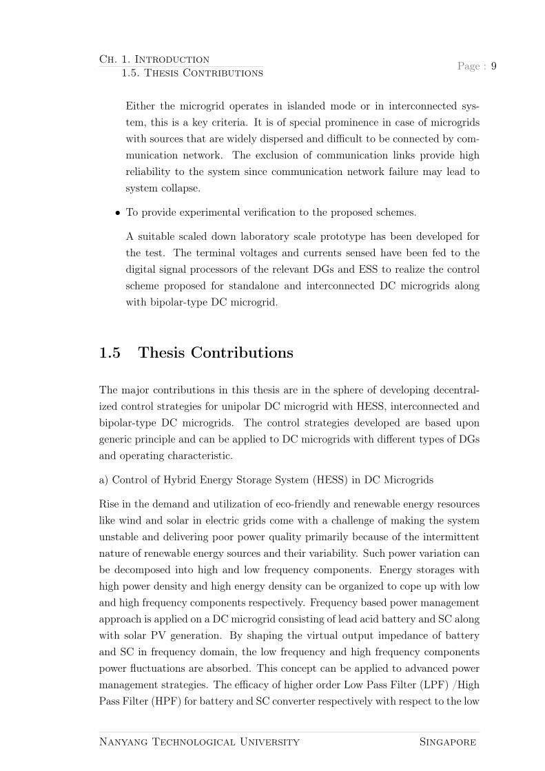
Either the microgrid operates in islanded mode or in interconnected sys-tem, this is a key criteria. It is of special prominence in case of microgridswith sources that are widely dispersed and difficult to be connected by com-munication network. The exclusion of communication links provide highreliability to the system since communication network failure may lead tosystem collapse.
• To provide experimental verification to the proposed schemes.
A suitable scaled down laboratory scale prototype has been developed forthe test. The terminal voltages and currents sensed have been fed to thedigital signal processors of the relevant DGs and ESS to realize the controlscheme proposed for standalone and interconnected DC microgrids alongwith bipolar-type DC microgrid.
1.5 Thesis Contributions
The major contributions in this thesis are in the sphere of developing decentral-ized control strategies for unipolar DC microgrid with HESS, interconnected andbipolar-type DC microgrids. The control strategies developed are based upongeneric principle and can be applied to DC microgrids with different types of DGsand operating characteristic.
a) Control of Hybrid Energy Storage System (HESS) in DC Microgrids
Rise in the demand and utilization of eco-friendly and renewable energy resourceslike wind and solar in electric grids come with a challenge of making the systemunstable and delivering poor power quality primarily because of the intermittentnature of renewable energy sources and their variability. Such power variation canbe decomposed into high and low frequency components. Energy storages withhigh power density and high energy density can be organized to cope up with lowand high frequency components respectively. Frequency based power managementapproach is applied on a DC microgrid consisting of lead acid battery and SC alongwith solar PV generation. By shaping the virtual output impedance of batteryand SC in frequency domain, the low frequency and high frequency componentspower fluctuations are absorbed. This concept can be applied to advanced powermanagement strategies. The efficacy of higher order Low Pass Filter (LPF) /HighPass Filter (HPF) for battery and SC converter respectively with respect to the low
Nanyang Technological University Singapore

Page : 10 Ch. 1. Introduction1.5. Thesis Contributions
order filters has been investigated. Utilizing second order filters are expected tobetter attenuate the noisy output and ripple power in DC microgrid with HESS.The coordination of battery and SC along with the static and dynamic powersharing have been verified through experiments.
b) Control of two interconnected DC microgrids with tie-line
An ESS can address the renewable intermittency in an islanded DC microgridenhancing the reliability and making the system more stable. In addition, theinterconnection of neighboring DC microgrids for exchange of power can furtherenhance the reliability. Forming multiple DC microgrid clusters by connectingmultiple identical DC buses via tie-line also aids in making the system more ef-ficient and reliable. The primary challenge in interconnecting DC microgrids iskeeping the system stable, since the involvement of multiple parallel convertersin a DC microgrid cluster make the system unstable. A decentralized control ap-proach for controlling the bus voltage of geographically dispersed microgrids in anallowable range can manage the power flow via tie-line across the microgrid. Suchapproach being decentralized, is void of communication stress. A mode adap-tive decentralized control is adopted for seamless mode transition in operationmodes of the microgrid. Thus, the distributed units can cope up with power flowcontrol and Bus Voltage Regulation (BVR) providing autonomy to the intercon-nected microgrids. In case of power deficit, power is injected/generated into/fromthe microgrid caused by demand-supply mismatch in a particular microgrid. Thegeneration sharing is facilitated by interconnecting the microgrids via tie-line insuch case. In absence of power supply deficit, every microgrid operates as an au-tonomous unit curtailing the generation in case of surplus in power supply. Thedynamic operation during variation in the source/load of microgrids has beenevaluated maintaining the bus voltage.
c) Control of bipolar-type DC microgrids
Bus voltage is considered as a global carrier of information to designate systempower balance in decentralized control of DC microgrids. Although, the threewire bipolar DC microgrid consists of three terminals and provide flexibility inthe connection of loads through remaining wires even when one wire fails, it hascertain challenges. Due to the different loading in upper and lower terminals, thebipolar DC microgrid gets unbalanced as the consequence of voltage fluctuationfrom nominal value at respective terminals. For this purpose, a voltage balancer isrequired in such microgrids. The use of decentralized control approach reduces the
Nanyang Technological University Singapore

Ch. 1. Introduction1.6. Organization of the Thesis
Page : 11
communication stress on the state-of-the art proposed systems with central voltagebalancer in bipolar-type DC microgrids. The decentralized voltage balancer cancreate control conflict when there exist two bus regulating units in the microgrid.An improved bipolar-type DC microgrid is proposed where decentralized controlfor parallel converters interfacing DERs is implemented with droop control baseddecentralized voltage balancing circuit. The control conflict between the two volt-age balancing circuits involved to regulate the bus voltage have been mitigated bythe proposed decentralized control for voltage balancing. The controller designedfor bipolar-type DC microgrid can converge the pole voltages to nominal value inshort time after the transient response due to load change.
1.6 Organization of the Thesis
This thesis consists of six chapters. The contents of this thesis are organized asfollows.
this Chapter discusses the rapid increase in utilization of DC microgrids andthe challenges associated with its development in the power industry, which is themotivation behind the writing of this thesis. The basic hardware topologies of DCmicrogrids have been discussed with illustrations highlighting the advantages anddisadvantages of such commonly used existing topologies along with the reasonsthat have been the hindrance in DC microgrid deployment. Research objectivesfocussing decentralized control in DC microgrids are elaborated. Summary ofmajor contributions have been pointed out.
Chapter 2, reviews the constituent of DC microgrids, compares various energystorage technologies and proposes hybridization of energy storage system with highspecific power and specific energy as the solution to compensate the power fluc-tuation in autonomous microgrids that is not achieved by a single energy storage.The existing DC microgrid topologies have been summarized. The coordinationcontrol strategies of DC microgrids comprising of renewable energy sources, energystorages and HESS are elaborated.
Chapter 3, investigates decentralized control of DC microgrids and explores fre-quency coordinating virtual impedance concept for the co-ordination control of anHESS in DC microgrid. Power decoupling methods to better attenuate the ripplepower by filtration have been investigated and the effectiveness of the proposedconcept is verified through simulation and experimental results.
Nanyang Technological University Singapore

Page : 12 Ch. 1. Introduction1.6. Organization of the Thesis
Chapter 4 discusses about the interconnection of DC microgrids to form a DCmicrogrid cluster with tie-line. It proposes decentralized control strategy for in-terconnection of two DC microgrids with tie-line. Mode adaptive decentralizedcontrol for these DC microgrids has been proposed where the bus voltage of eachmicrogrid is controlled to ensure the regulation of bus voltage deviations. Theeffectiveness of proposed decentralized control has been validated experimentallyin two interconnected DC microgrids.
Chapter 5, explores bipolar-type DC microgrids and decentralized voltage bal-ancing control is proposed in bipolar-type DC microgrids. An improved droopcontrol is implemented to mitigate control conflict due to two bus voltage con-trollers in a system and to validate the decentralized control of bipolar-type DCmicrogrid for both load sharing and voltage balancing.
Finally, in Chapter 6, this thesis is summarized and future research directionsare recommended.
Nanyang Technological University Singapore

Chapter 2
Configuration and Control of DCmicrogrids
We’re looking at it closely, butthere are some obstacles. Someare technical; we need some con-trol technologies. We’d like tosee it more broadly implemented.From an economic standpoint,there’s still a question of whereand when they make sense.
—Haresh Kamath, ARPA-EEnergy Summit 2014, on technical
issues of microgrids
This chapter reviews the configuration of DC microgrid topologies, classificationof control strategies and the elements of DC microgrids. Desired control require-ments have been identified and deployed from Chapter 3 onwards. Along with thecontrol of power electronic converters for solar PV and battery, this chapter re-views the state of-the-art in energy storage technologies and discusses the essenceof hybridization of energy storage system in DC microgrids.
13

Page : 14 Ch. 2. Configuration and Control of DC microgrids2.1. Review on Constituents of DC Microgrids
Figure 2.1: Equivalent circuit of typical PV module (a) Simplest model (b) So-phisticated model
2.1 Review on Constituents of DC Microgrids
2.1.1 Solar PV System
The simplest model of solar PV panel can be represented as a current source withan anti-parallel diode and series resistance Rs as shown in Fig. 2.1(a). The paralleldiode is determinant of the I-V characteristics of the solar cell and the output ofthe current source is directly proportional to the solar irradiance. A sophisticatedmodel can be represented with a shunt resistance Rsh in parallel with the diode [40]as shown in Fig. 2.1(b). The equations to represent the output current of solarcell are given as follows:
IPV = npIph − npIsat × exp
[q
AkTs
(VPV
ns
+ IPVRs
)− 1
](2.1)
Iph = (Isc +Ki(Ts − Tr)) S
1000(2.2)
Isat = Irr
(TsTr
)3
exp
(qEgap
kA
(1
Tr− 1
Ts
))(2.3)
Where,
IPV : Output current of solar PV;
Iph: Photocurrent;
Isat: Saturation current;
Nanyang Technological University Singapore

Ch. 2. Configuration and Control of DC microgrids2.1. Review on Constituents of DC Microgrids
Page : 15
Isc: Short-circuit current;
q: Electron charge;
A: Ideality factor;
k: Boltzman constant;
S: Solar irradiation;
VPV : Output voltage of solar PV;
ns: Number of solar cells in series;
np: Number of solar cells in parallel;
Ki: Temperature coefficient of short circuit current;
Ts: Surface temperature of the PV cell;
Tr: Reference temperature;
Irr: Reverse saturation current at temperature Tr;
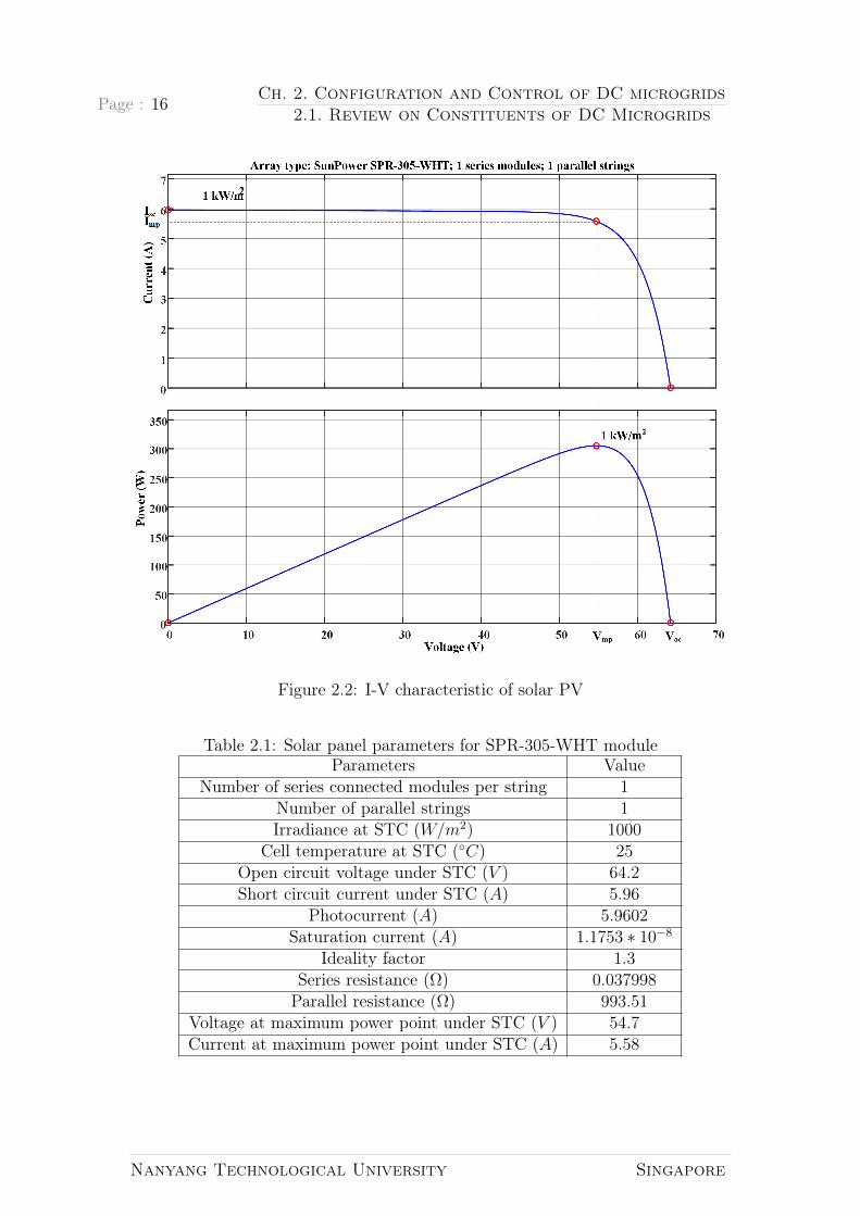
The I-V characteristic of solar PV panel explained by (2.1)- (2.3) is depictedin Fig. 2.2. The curves are generated from Matlab for module type SPR-305-WHT by SunPower, and the manufacturer specifications are listed in Table 2.1.Isc corresponds to the short-circuit current which is obtained when the outputvoltage of PV (VPV ) is zero and Voc corresponds to the open-circuit voltage ofPV when the output current of PV is zero. Isc and Voc are the maximum valuesof current and voltage that can be obtained from a PV cell under Standard TestCondition (STC).
The power of the PV cell can be obtained by multiplying its output voltage andcurrent. From Fig. 2.2, it can be seen that the power increases with increase involtage of the PV cell reaching maximum point however, it further decreases fromthis maximum point. This point is termed as Maximum Power Point (MPP) andthe corresponding current Imp and voltage Vmp to achieve maximum power areindicated in Fig. 2.2.
Power Electronics for solar PV
The integration of solar PV to the DC bus is done by the means of interfacingconverter termed as DC-DC boost converter. The schematic layout of DC-DCboost converter is shown in Fig. 2.3(a). The operating principle of the DC-DCboost converter is based on the periodic accumulation of energy and transferring
Nanyang Technological University Singapore
Page : 16 Ch. 2. Configuration and Control of DC microgrids2.1. Review on Constituents of DC Microgrids
Figure 2.2: I-V characteristic of solar PV
Table 2.1: Solar panel parameters for SPR-305-WHT moduleParameters Value
Number of series connected modules per string 1Number of parallel strings 1Irradiance at STC (W/m2) 1000
Cell temperature at STC (C) 25Open circuit voltage under STC (V ) 64.2Short circuit current under STC (A) 5.96
Photocurrent (A) 5.9602Saturation current (A) 1.1753 ∗ 10−8
Ideality factor 1.3Series resistance (Ω) 0.037998Parallel resistance (Ω) 993.51
Voltage at maximum power point under STC (V ) 54.7Current at maximum power point under STC (A) 5.58
Nanyang Technological University Singapore

Ch. 2. Configuration and Control of DC microgrids2.1. Review on Constituents of DC Microgrids
Page : 17
it through inductor L in the circuit with capacitor C and load. The operationof solar PV converter in DC microgrid can be classified as MPPT mode and BusRegulating Mode (BRM).
Figure 2.3: Solar PV converter a) Schematic representation of DC-DC boost con-verter b) Controller for solar PV converter
During MPPT mode, the terminal voltage of PV panel is generated from theMPPT block as shown in Fig. 2.3(b) where, PPV denotes the PV output power.The dual loop Proportional-Integral (PI) controller consists of outer voltage controlloop and inner current control loop. The function of outer voltage control loop isto generate the reference current (i∗L) for inner current control loop and is obtainedby processing the difference of reference and actual terminal voltage of the solarPV. The inner current control loop consists of another PI controller to minimizethe current tracking error and generate the duty ratio for the PV converter dPV .PWM generates the switching signal (GPV ) for the power electronic switch S11 to
Nanyang Technological University Singapore

Page : 18 Ch. 2. Configuration and Control of DC microgrids2.1. Review on Constituents of DC Microgrids
realize boost operation of PV converter.
In bus regulating mode, the reference output voltage of PV converter is trackedby a double loop PI-controller. The function of outer voltage and inner currentcontrol loops are same as explained above.
The relationship between the input voltage (VPV ) and output voltage (VPV o) ofthe PV converter is expressed as in (2.4).
VPV o =1
1− dPV
VPV (2.4)
2.1.2 Energy Storage System
Several researches have been carried out in the area of energy storage and ESS.Depending upon the compensations for power fluctuations from seconds to hours,energy storage technologies are divided into short term, medium term and longterm [41] including standalone systems [42]. Energy storage technologies can beclassified into, as follows [43]:
• Mechanical Storage System: It comprises of technologies like hydro, com-pressed air and flywheel storage system.
• Electrical Storage System: Capacitors and Ultra capacitors fall in this cate-gory.
• Electromagnetic Energy Storage System: Superconducting Magnetic EnergyStorage (SMES) represents this system.
• Electrochemical Energy Storage System: Traditional batteries and flow bat-teries represent this category.
Mechanical Storage System like Compressed Air Energy Storage (CAES) and hy-dro energy storages are able to provide energy for longer course of time rangingfrom hours to even days since they can store large amount of energy. However,the response time is slow [28].
SMES are highly efficient, up to 95%, with fast response time but the cost ofrefrigeration and superconducting wire make it very expensive [28]. They findtheir use in low energy high power applications.
Ultracapacitors carry long lifetime and are highly efficient. They have low energydensity in comparison to lead-acid batteries and are costly. However, their fast
Nanyang Technological University Singapore

Ch. 2. Configuration and Control of DC microgrids2.1. Review on Constituents of DC Microgrids
Page : 19
response provides short burst of power [28], thus, they find their use in low energyhigh power applications.
Researchers have paid high attention to chemical batteries lately. Traditional bat-teries like Lithium ion (Li-ion), sodium sulphide and flow batteries like vanadiumredox have proved to be efficient by new technologies, Li-ion carrying nearly 100%round trip efficiency and sodium sulphide and vanadium redox providing 85% and80% efficiency [44]. However, there will be a loss in the interface [28] since batteriesstore energy in DC and they need power electronic interface for energy conversion.
To have a better idea about the efficiency, specific energy, specific power, lifetimeetc. of chemical batteries and ultracapacitors a literature survey is conductedand tabulated in Appendix A. References for the above mentioned parameters forwidely used chemical batteries such as Vanadium Redox flow Battery (VRB), leadacid battery, Nickel-Cadmium (NiCd), Nickel-Metal Hydride (NiMH) and Li-ionalong with SC are tabulated.
Based upon the summary tabulated in Table 2.2, Li-ion batteries are the bestcandidate for hybrid energy storage application in terms of parameters like ef-ficiency and energy density. Besides high cost, Li-ion batteries are superior toother chemical batteries in every aspect. Supercapacitors show best performancein terms of power density, efficiency and lifetime (cycles). Combination of Li-ionand SC hence compensate the gap of high energy density and high power densityand hence prove to be the best solution for hybrid energy storage applications.
Power Electronics for energy storages
The energy storage together with interfacing converter to the DC bus is termedas Energy Storage Systems (ESS). Bi-directional boost converter is illustrated inFig. 2.4(a) for battery converter. The low voltage side is connected to the terminalof energy storage devices and the output side Vbo is connected to the DC bus.Converter operation signifies charging mode when S12 is modulated with PWM andgate signal (Gbat) of S11 is turned off. dbat denotes the duty ratio generated by theinner current control loop for the battery converter. The discharging mode takesplace when S11 is modulated in the PWM and gate signal of S12 is turned off. Twodriver circuits to command integrated bipolar transistors (IGBTs) are required forthis topology. This topology has the benefits of providing simple structure andlow number of components utilized for its construction, which enhances the lowcost operation. The two modes of operation for a battery converter are PowerControl Mode (PCM) and BRM as shown in Fig. 2.4(b). The BRM in battery
Nanyang Technological University Singapore

Page : 20 Ch. 2. Configuration and Control of DC microgrids2.1. Review on Constituents of DC Microgrids
Table2.2:
Tabulationofparam
etriccom
parisonofdifferent
storagetechnologies
XX
XXX
XXX
XXXX
Param
eterStorage
VRB
Gen.
1Lead-acid
NiCd
NiM
HLi-ion
Supercap.
Efficiency
(%)
60..8575..80
60..7565..70
90..9590..95
Temperature
[ C]
+10..+
40-20..+
60-30..+
60-20..+
60-30..+
60-45..+
60Specific
energy[W
h/kg]10..30
25..4035..65
60..9090..180
5Specific
power
[W/kg]
100..200150..250
250..750750..1500
2.5k..5kRecharge
rate[×
C]
0.10.2..1
0.2..0.50.8..1
1C
Self-discharge[%
/month]
33
1010
5>100
Lifetime[cycles]
12k..14k500..1000
1500..3000500..1000
1.5k..7.5k0.5M
..1MMaintenance
High
High
Moderate
High
None
None
InitialcostLow
Moderate
Moderate
High
Very
highCycle
cost[¢/kW
h/cycle]5..80
2749
3440
5.4
Nanyang Technological University Singapore

Ch. 2. Configuration and Control of DC microgrids2.1. Review on Constituents of DC Microgrids
Page : 21
Figure 2.4: Battery converter a) Schematic layout of bi-directional DC-DC con-verter b) Controller for battery converter
converter is similar to that of PV converter explained above in 2.1.1.
The PCM corresponds to the generation of reference inductor current i∗L for innercurrent control loop by dividing the battery bank output power (Pbat) with batterybank terminal voltage (Vbat).
2.1.3 Hybrid Energy Storage System
Energy storage forwards itself as a reliable technology for smoothing renewableintermittency. It does not use fossil fuel and is energy secure and eco-friendly [31].
Nanyang Technological University Singapore

Page : 22 Ch. 2. Configuration and Control of DC microgrids2.1. Review on Constituents of DC Microgrids
The primary goal of integrating energy storages in microgrid with renewable energysources is to provide consistent quality of power supply. Even though the powercost is minor, the energy cost for the existing storage technologies being deployedis expensive. Thus, their discharge time is thirty minutes at full power or evenless [45].
Energy storages can be classified based on their ramp rate (kW/s), specific power(kW/Kg), life cycles, specific energy (kWh/Kg), etc. [46,47]. An individual BESSis not able to fulfill all the mentioned requirements [47]. Although various tech-nologies have been deduced for BESS, they suffer from poor life span of less than1000 full cycles which can further deteriorate in case of deep discharge cycles [35].Lead acid battery being cost friendly are the dominant type of BESS. On the otherhand, Li-ion battery that is one of the most efficient chemical battery is very expen-sive [35] and is available limitedly. ESS based on chemical battery is characterizedby their specific energy but suffer from low power capacity compared to technolo-gies like SC. A supercapacitor (SC), also termed as Electrochemical Double LayerCapacitor (EDLC) or Ultracapacitor (UC) [48] has high life cycle, low internalresistance, 10-100 times higher specific power compared to chemical batteries [49]and high charge/discharge efficiency [48, 50]. On the flip side, chemical batterieslike Li-ion have high charge/discharge efficiency with low rate of discharge andhigh specific energy.
The present energy storage system does not meet the characteristic of having highpower density along with high energy density. High power density addresses powervariations and high energy density provides autonomy to micro grids [51]. Theneed of energy storage system, which is able to provide both high power densityand high energy density in microgrid is only possible by integrating two differentenergy storages having the above mentioned quality.
Research demonstrate that improved performance can be achieved by combiningSC and batteries despite the presence of batteries with high specific power [35,48, 52–54]. It is because large batteries have cost constraints. Also, cell voltagebalancing degrade the capacity of battery packs overtime leading to battery systemfailure. Thus, to compensate the peak power demand, supercapacitors are opted.Other major factor for hybridization is the topology selection for power electronicinterface [52,53].
Power Electronics for HESS
An HESS having two energy storages can be categorized variously based on the
Nanyang Technological University Singapore

Ch. 2. Configuration and Control of DC microgrids2.1. Review on Constituents of DC Microgrids
Page : 23
position and connection of converter interface and position of SC/battery. Thepower levels, control and application decide the best suited configuration. Theconfiguration of HESS structure and topology of power electronic interface is re-viewed in the following section [55].
A. Direct connection of HESS
The passive configuration of battery/SC HESS is shown in Fig. 2.5(a). The absenceof power electronic converters reduces the cost and the ease of implementationmaking the system simple [50], but the power sharing between battery and SC islimited since there is no regulation of terminal voltage in such configuration. Apower electronic interface in SC can aid in the complete utilization of energy ofthe SC [50, 53]. In addition, reduction in ripple of source current, better outputvoltage regulation and lower weight and volume can be ensured with the activeHESS configuration [48,50].
B. SC connected only to DC-DC converter
For effective utilization of SC energy, DC-DC converter is used to connect SC tothe DC bus as shown in Fig. 2.5(b). Since the battery is in direct connection tothe DC bus, voltage variation of DC bus cannot be achieved. This configurationlacks the presence of buffer between load and battery that might damage thebattery [52,53].
C. Battery only connected to DC-DC converter
The SC is connected to the DC bus directly as shown in Fig. 2.5(c) and acts asa low pass filter due to which the working range of SC is limited [52, 53]. Evenduring rapid change in power flow, the battery is protected in this topology sinceSC acts as buffer in such conditions [52].
D. Battery/SC cascaded by means of DC-DC converters
This topology is formed by using additional DC-DC converter between the DC busand SC in Fig. 2.5(d). Addition of this DC-DC converter in the topology expandsthe working range of the SC. However, use of additional DC-DC converter meansthe topology becomes costly and it must handle the total load power.
E. Battery/SC in parallel with the DC bus
The DC bus and the battery/SC HESS are connected parallel in this topology asseen in Fig. 2.5(e). This parallel arrangement improves performance as the controlof power flow can be performed as per the energy flow control [52]. Full utilization
Nanyang Technological University Singapore
Page : 24 Ch. 2. Configuration and Control of DC microgrids2.1. Review on Constituents of DC Microgrids
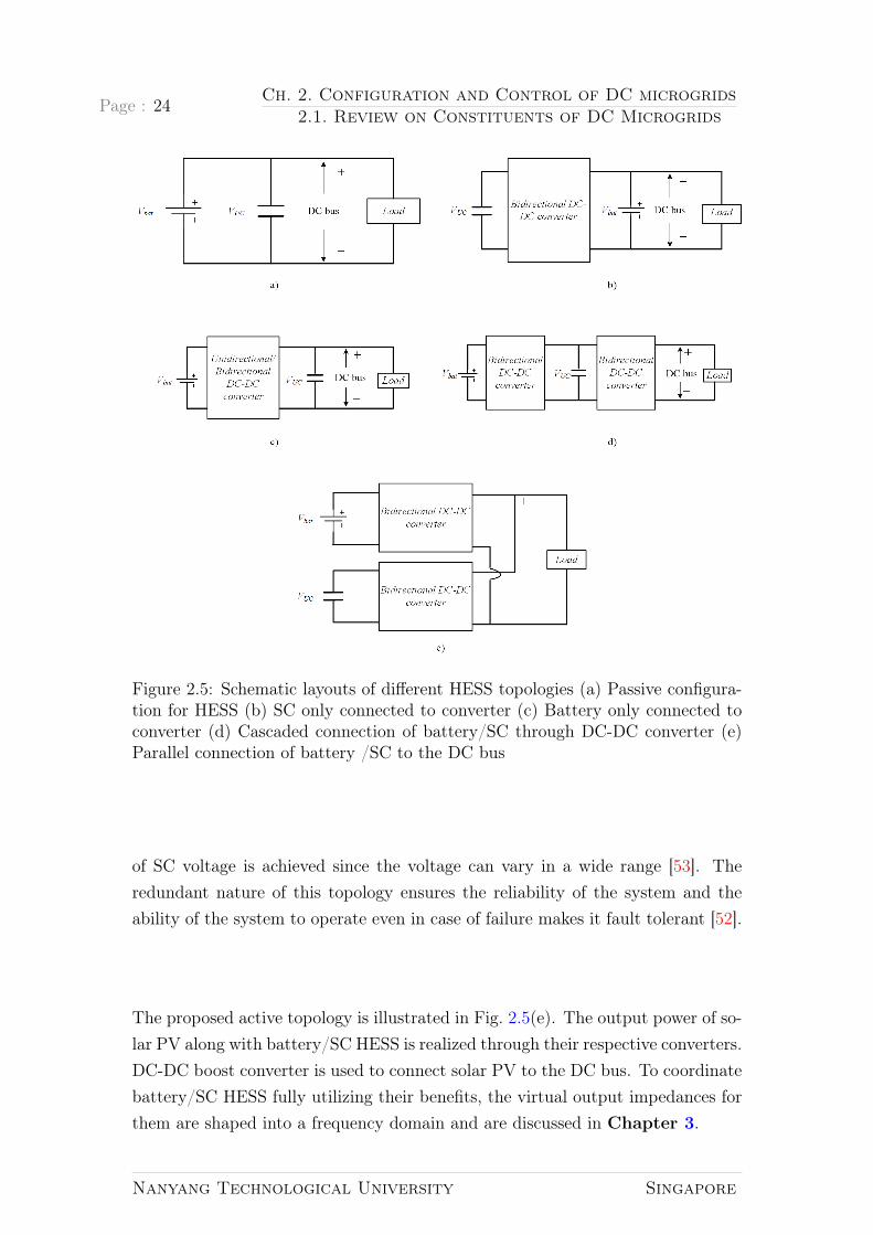
Figure 2.5: Schematic layouts of different HESS topologies (a) Passive configura-tion for HESS (b) SC only connected to converter (c) Battery only connected toconverter (d) Cascaded connection of battery/SC through DC-DC converter (e)Parallel connection of battery /SC to the DC bus
of SC voltage is achieved since the voltage can vary in a wide range [53]. Theredundant nature of this topology ensures the reliability of the system and theability of the system to operate even in case of failure makes it fault tolerant [52].
The proposed active topology is illustrated in Fig. 2.5(e). The output power of so-lar PV along with battery/SC HESS is realized through their respective converters.DC-DC boost converter is used to connect solar PV to the DC bus. To coordinatebattery/SC HESS fully utilizing their benefits, the virtual output impedances forthem are shaped into a frequency domain and are discussed in Chapter 3.
Nanyang Technological University Singapore

Ch. 2. Configuration and Control of DC microgrids2.2. Review on Configuration of DC microgrids
Page : 25
2.2 Review on Configuration of DC microgrids
Several hardware topologies of DC microgrids have been reported depending uponthe specific application. The basic criteria lie in control flexibility, robustnessand reliability. The basic topologies of DC microgrid can be classified into threecategories [37]:
2.2.1 Single Bus Topology
Figure 2.6: Schematic layout of an unipolar DC microgrid
The single bus topology that is commonly used for DC microgrids has been shownin Fig. 2.6 and is effective in industrial applications. The DC bus in such con-figuration consists of positive and negative poles. One of the important factor insuch topology is the selection of DC bus voltage level since the energy is trans-mitted over one bus voltage level [38]. Power transmission capability is enhancedby voltage level but the number of interfacing DC-DC converters is increased tomeet the requirement of consumer voltage level [38]. Low voltage level limits thetransmission capability to only in a short distance. However, it can be effectivein remote rural areas where utility grid is not feasible. A 48V single bus topology
Nanyang Technological University Singapore
Page : 26 Ch. 2. Configuration and Control of DC microgrids2.2. Review on Configuration of DC microgrids
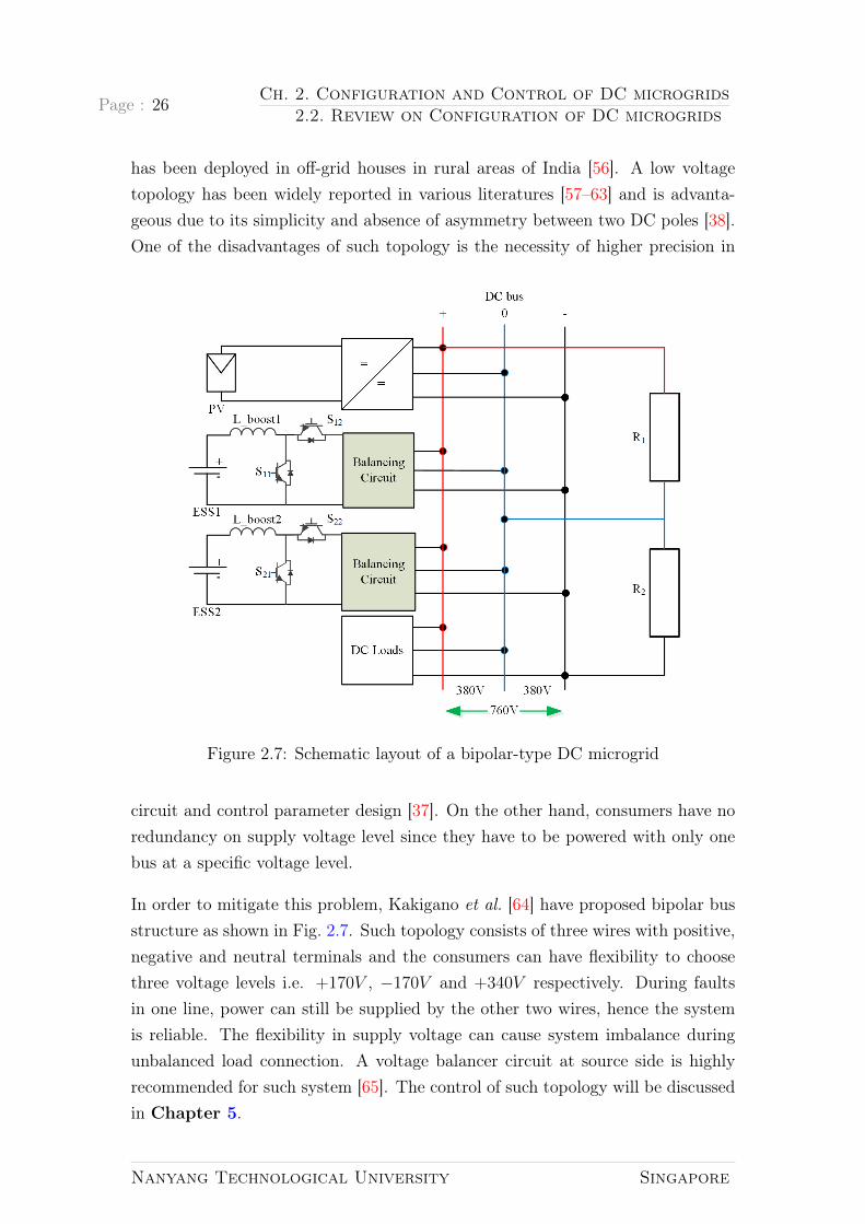
has been deployed in off-grid houses in rural areas of India [56]. A low voltagetopology has been widely reported in various literatures [57–63] and is advanta-geous due to its simplicity and absence of asymmetry between two DC poles [38].One of the disadvantages of such topology is the necessity of higher precision in
Figure 2.7: Schematic layout of a bipolar-type DC microgrid
circuit and control parameter design [37]. On the other hand, consumers have noredundancy on supply voltage level since they have to be powered with only onebus at a specific voltage level.
In order to mitigate this problem, Kakigano et al. [64] have proposed bipolar busstructure as shown in Fig. 2.7. Such topology consists of three wires with positive,negative and neutral terminals and the consumers can have flexibility to choosethree voltage levels i.e. +170V , −170V and +340V respectively. During faultsin one line, power can still be supplied by the other two wires, hence the systemis reliable. The flexibility in supply voltage can cause system imbalance duringunbalanced load connection. A voltage balancer circuit at source side is highlyrecommended for such system [65]. The control of such topology will be discussedin Chapter 5.
Nanyang Technological University Singapore
Ch. 2. Configuration and Control of DC microgrids2.2. Review on Configuration of DC microgrids
Page : 27
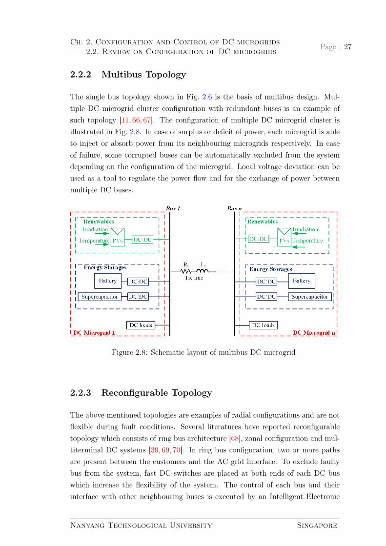
2.2.2 Multibus Topology
The single bus topology shown in Fig. 2.6 is the basis of multibus design. Mul-tiple DC microgrid cluster configuration with redundant buses is an example ofsuch topology [11, 66, 67]. The configuration of multiple DC microgrid cluster isillustrated in Fig. 2.8. In case of surplus or deficit of power, each microgrid is ableto inject or absorb power from its neighbouring microgrids respectively. In caseof failure, some corrupted buses can be automatically excluded from the systemdepending on the configuration of the microgrid. Local voltage deviation can beused as a tool to regulate the power flow and for the exchange of power betweenmultiple DC buses.
Figure 2.8: Schematic layout of multibus DC microgrid
2.2.3 Reconfigurable Topology
The above mentioned topologies are examples of radial configurations and are notflexible during fault conditions. Several literatures have reported reconfigurabletopology which consists of ring bus architecture [68], zonal configuration and mul-titerminal DC systems [39, 69, 70]. In ring bus configuration, two or more pathsare present between the customers and the AC grid interface. To exclude faultybus from the system, fast DC switches are placed at both ends of each DC buswhich increase the flexibility of the system. The control of each bus and theirinterface with other neighbouring buses is executed by an Intelligent Electronic
Nanyang Technological University Singapore

Page : 28 Ch. 2. Configuration and Control of DC microgrids2.2. Review on Configuration of DC microgrids
Figure 2.9: Schematic layout of a DC microgrid ringbus topology
Device (IED) [68]. In case of failure of a bus, the IED identifies and excludesit from the system and renders an alternative path for power supply to the cus-tomer. Thus, in comparison to radial system, the ring or loop configuration shownin Fig. 2.9 has high reliability. Such system of distribution is particularly signifi-cant in industrial and urban areas. The disadvantage of such system is that if anyfault occurs in the AC feeder, the DC microgrid system will be deprived of powersupply.
Figure 2.10: Schematic layout of a multiterminal DC microgrid
A mesh type or Multiterminal DC systems (MTDC) illustrated in Fig. 2.10 con-sist of multiple utility grids interfaced with multiple DC buses through AC-DCconverter.The availability of supplementary feeders for power supply to auxiliaryparts of the system make MTDC more reliable than the loop or the radial DCgrids. Similar frameworks are utilized in underground urban sub-transmission
Nanyang Technological University Singapore

Ch. 2. Configuration and Control of DC microgrids2.3. Review on Control of DC microgrids
Page : 29
and distribution systems and off-shore wind farms which are High Voltage DirectCurrent (HVDC) system [71,72].
Figure 2.11: Schematic layout of a zonal DC microgrid
A Zonal Type DC (ZTDC) microgrid system shown in Fig. 2.11 where the dis-tribution system has sub-divison of number of zones with each zone having tworedundant DC buses has been proposed in [69, 73] to make the system more re-liable providing flexibility in load power supply. The higher number of switchesmake this configuration more flexible and suitable for distribution planning. TheZTDC grid can supply power to loads through different means like: exclusivelyfrom one bus and sequentially or simultaneously from multiple buses. Having saidso, complication in the design and operation of the distribution system may arisefrom drawing power through multiple buses [74,75]. ZTDC can find its applicationon ship board power systems [76].
2.3 Review on Control of DC microgrids
Control strategies for DC microgrids can be classified as centralized, decentralizedand distributed depending upon the communication link [77–81] and are discussedas follows.
Nanyang Technological University Singapore

Page : 30 Ch. 2. Configuration and Control of DC microgrids2.3. Review on Control of DC microgrids
2.3.1 Centralized Control
Centralized control can be best understood by explaining three major classifica-tions [82, 83]:
• Local Controllers (LCs) which are subdivided into microsource controllersand load controllers
• Central controllers
• Distribution Management System (DMS)
The aim of local controllers is to control the operating points of microsources andtheir power electronic interfaces with no communication link between them. Loadcontrollers are used for demand side management and are installed at controllableloads. The objective of a central controller is to provide simple co-ordination oflocal controllers for the optimization of microgrid operation acting as an interfacebetween the distribution management system and the microgrid. Management ofthe operation of low and medium voltage areas with multiple microgrid can be doneusing DMS or Distribution Network Operator (DNO) having several interfacedMicrogrid Central Controllers (MGCCs). In case of microgrids participating inthe market, Market Operators (MO) exist in the system. MO and DNO representutility and are not the part of microgrids [83].
In case of small scale microgrids, master slave approach is employed [84,85]. Thistype of control depends on the rapid communication amidst the source and loadconverters. One of the converter controls the DC bus voltage and is obliged todistribute power reference to other source converters [86]. This master converter,which acts as a voltage source converter, fixes the current references for otherslave converters acting as current source converter as shown in Fig. 2.12. To avoidsystem failures, another module in the system acts as master if the master unitfails. The role of the master defines different ways of control. The master mightbe one fixed module or it might be arbitrarily chosen or the module bringingmaximum current becomes master module.
Hierarchical control which consists of different control levels is often preferred forlarger scale DC microgrids [77] as shown in Fig. 2.13. Such control consists oflocal converter control and a Digital Communication Link (DCL) based coordi-nated control. DCL based coordinated control is utilized to perform advancedenergy management functions. For DC microgrid based application in data center
Nanyang Technological University Singapore
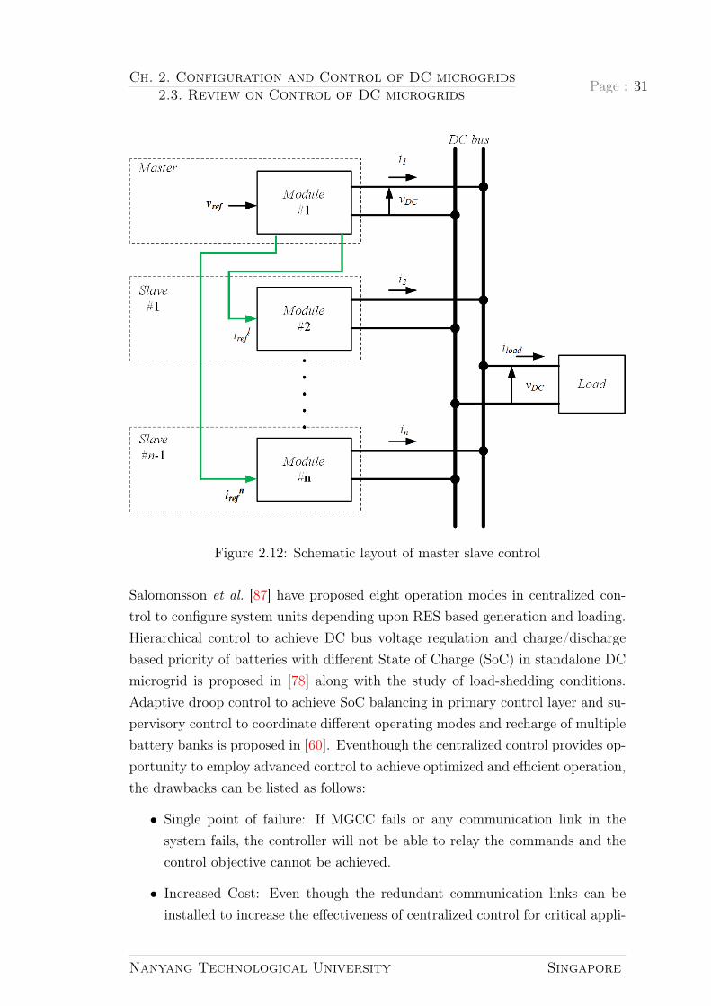
Ch. 2. Configuration and Control of DC microgrids2.3. Review on Control of DC microgrids
Page : 31
Figure 2.12: Schematic layout of master slave control
Salomonsson et al. [87] have proposed eight operation modes in centralized con-trol to configure system units depending upon RES based generation and loading.Hierarchical control to achieve DC bus voltage regulation and charge/dischargebased priority of batteries with different State of Charge (SoC) in standalone DCmicrogrid is proposed in [78] along with the study of load-shedding conditions.Adaptive droop control to achieve SoC balancing in primary control layer and su-pervisory control to coordinate different operating modes and recharge of multiplebattery banks is proposed in [60]. Eventhough the centralized control provides op-portunity to employ advanced control to achieve optimized and efficient operation,the drawbacks can be listed as follows:
• Single point of failure: If MGCC fails or any communication link in thesystem fails, the controller will not be able to relay the commands and thecontrol objective cannot be achieved.
• Increased Cost: Even though the redundant communication links can beinstalled to increase the effectiveness of centralized control for critical appli-
Nanyang Technological University Singapore

Page : 32 Ch. 2. Configuration and Control of DC microgrids2.3. Review on Control of DC microgrids
Figure 2.13: General schematic layout of centralized control
cations, the system will not be cost effective.
• Reduced flexibility and expandability: The MGCC should be redesigned orreprogrammed even to increase the number of DGs in the system.
2.3.2 Distributed Control
The concept of distributed control has evolved due to the rapid development incommunication technologies and information exchange algorithms [88,89]. The dif-ference in distributed control in comparison with centralized control is that it doesnot consist of central controller. The local controllers communicate through DCLsas shown in Fig. 2.14 such that the important information is shared. Distributedcontrol is resistant to single point of failure because the communication networkremains effective eventhough there is failure in some communication links [77].However, the modality of information exchange between LCs through DCLs is achallenge. In order to achieve coordination among distributed units through eachother’s data access directly to fulfill control objectives, consensus algorithm canbe used [90].
Consensus algorithm is a simple agreement established in every local controllers
Nanyang Technological University Singapore

Ch. 2. Configuration and Control of DC microgrids2.3. Review on Control of DC microgrids
Page : 33
to sum up the algebraic differences of variable(s) of interest located at particularlocal controller and the local controller adjacent to it. Mathematically, for anygiven ith local controller,it can be expressed as [77]:
xi(t) =∑j∈Ni
[xi(t)− xj(t)] + bi(t) (2.5)
Where, xi(t) and xj(t) are the parameters of interest of ith and jth local controllersas mentioned above. Iteration j is carried out through all set of neighbours of ith
local controller and represented by Ni. And, bi(t) is the input bias of local con-troller and is optional. Any controller parameters adjust their values with respectto their neighbour values as xi(t) expressed in (2.5). Convergence of all parametersto common average value is ensured in some period if the communication networkremains linked [91].
Figure 2.14: Schematic layout of distributed control
Consensus algorithms [62, 63, 92–94] have been employed to achieve distributedcontrol in microgrids, recently. A consensus algorithm with sparse communicationnetwork is used in [63] and [92] to achieve a distributed secondary control diagramwith dynamic averaging. For restoring voltage and enhancing current sharingaccuracy, information is acquired only from neighboring converters rather thanglobal information from all the converters. This also results in the reduction ofcommunication stress on the system. The flexibility of the system is enhanced by
Nanyang Technological University Singapore

Page : 34 Ch. 2. Configuration and Control of DC microgrids2.3. Review on Control of DC microgrids
utilizing consensus algorithm to achieve plug and play activity.
rd,i = r∗ +
(kp +
kirs
)(r − rdci) +
(kpc +
kics
)(idci − idci) (2.6)
rd,i = v∗dc − (r∗ +Gpir(rref − rdci)−Gpic(idci − idci))idci︸ ︷︷ ︸slope−adjusting−term
+ Gpiv(s)(v∗dc − vdci︸ ︷︷ ︸
voltage−shifting−term
)
(2.7)
Figure 2.15: Control diagram proposed by Wang et al.
Where, v∗dc is the DC bus voltage reference and v∗dci is the voltage reference of ith
converter. rdi, r∗, rdci and idci denote the droop coefficient, given reference value ofdroop coefficient, calculated average value of droop coefficients and output currentof the ith converter, respectively. The control parameters of the average droopcoefficients and average current regulators are given by kpr, kir, kpc and kic.
The DC bus voltage is maintained by shifting droop curves keeping droop coef-
Nanyang Technological University Singapore

Ch. 2. Configuration and Control of DC microgrids2.3. Review on Control of DC microgrids
Page : 35
ficient constant. This phenomenon is called voltage shifting method [94] and isapplied in [59, 62, 63, 92, 95]. The unequal equivalent output impedance gainedby adding mismatched line impedance of the converters and the constant droopcoefficient leads to inaccurate current sharing in parallel converters. This pointsthe importance of regulating the average current controller further in case of rapidchange of load current to maintain current sharing proportion. The droop coeffi-cient is adjusted by adding slope adjusting term [94] to enhance current sharingaccuracy in [63], however, its implementation to attain stability is complicated [94].Wang et al. proposes three compensating controllers to enhance the dynamic per-formance due to fast changing load currents [94]. One of the controllers solves theproblem of voltage deviation of DC bus caused by droop control and the rest twowork to adjust the droop coefficient in order to achieve same equivalent outputimpedance, thus, eliminating the current sharing error. The governing equationsfor the control diagram presented by Wang et al. [94] in Fig. 2.15 are given by(2.6) and (2.7). Although the functions and objectives such as voltage restoration,output current sharing, SoC balancing can be achieved by distributed control andresembles with centralized control, the main drawback is the complex analyticalperformance analysis such as convergence speed, stability margins etc. due tocommunication delays and measurement errors.
2.3.3 Decentralized Control
In decentralized control, the DG units are controlled by making independent deci-sions based on the local variables without any communication links. It is performedby LCs as shown in Fig. 2.16. The most common type of decentralized controlare DC Bus Signaling (DBS), adaptive adjustment of droop gain and Power LineSignaling (PLS) [77]. Decentralized control on the one hand has advantage of sim-plicity in control while on the other hand, it is disadvantageous because of lack ofcommunication between system units and is highly affected by sensor inaccuracy.
DC bus signaling
The decentralized coordination method for DC microgrid control using DC bus as acommunication link is termed as DBS. Due to the cumulative capacitance of everyDERs interfacing power electronic converters, the DC microgrid bus is capacitivein nature as shown in equivalent circuit in Fig. 2.17 where Pgen, Pload and Pbus
represent the generation, load and bus capacitor charging power, respectively.
Nanyang Technological University Singapore

Page : 36 Ch. 2. Configuration and Control of DC microgrids2.3. Review on Control of DC microgrids
Figure 2.16: Schematic layout of decentralized control
Vbus and Cbus denote the capacitance and voltage of bus capacitor respectively.Mathematical representation of system power balance can be expressed as (2.8)and (2.9). It can be seen from (2.9) that the change in bus voltage takes placedue to the change in generation and consumption (load) power. If generation ishigher than load power, bus voltage increases and vice versa. Hence, bus voltageacts as a global indicator for the system.
Figure 2.17: Equivalent circuit representing DC bus
Pbus(t) = Pgen(t)− Pload(t) (2.8)
Vbus(t)dVbus(t)
dt=
1
Cbus
(Pgen(t)− Pload(t)) (2.9)
In other words, DBS obeys the concept of charge/discharge scheduling of indi-vidual distributed sources. Scheduling of sources is achieved by the operationdependence of DERs interfacing converters on DC bus voltage level affiliated totheir charge/discharge threshold [96]. For the operation of multiple converters at
Nanyang Technological University Singapore

Ch. 2. Configuration and Control of DC microgrids2.3. Review on Control of DC microgrids
Page : 37
each threshold, voltage droop is implemented. Any change in the system causesthe change in voltage level of the DC bus which enforces the converters involvedin DC microgrid to switch to Constant Power (CP) or Constant Voltage (CV)mode [97]. In this way, source and storage converters in DC microgrid utilize DCbus voltage level to determine their mode of operation.
The details on implementation of DBS is provided in [77, 79] and [98] that wasoriginally proposed by [97]. The converters in DC microgrid operate to fulfill twoobjectives, i.e. to regulate the deviation of system voltage and to regulate thepower flow. This may lead to control conflict between the converters since at atime, only one operation mode is possible. Thus, the converters are classified asterminal regulating units and bus regulating units based on their control objec-tives [79]. Terminal regulating units serve as a constant power load/source in amicrogrid. They include non-controllable DGs and loads working at MPPT. Onthe other hand, bus regulating units maintain bus voltage based on the informa-tion gained from feedback signal. They identify themselves as voltage source sincethey work on making the microgrid stable during power variations.
The operating modes are classified into utility dominating, storage dominating andgeneration dominating in [77] and [79] to highlight the DBS principle as shown inFig. 2.18 [79]. It is considered that the microgrid consists of three possible sourcesi.e. DG, ESS and the utility and it consists of at least one bus regulating unit forsystem voltage stability. Hence, the modes are classified depending upon whichterminal (generation, storage and grid) takes the responsibility of bus regulation.When the local DG and ESS power are unable to meet the local demand, thepower deficit is imported from the utility grid. The interfacing converter actsas the bus regulating unit maintaining the system power balance as shown inFig. 2.18(a). When the microgrid consists of sufficient power and energy reservein its ESS, the renewable DGs work on MPPT to maximize energy harvest and theutility interfacing converter regulates power exchange with main grid according topower system operator. Such mode is termed as storage dominating mode and isshown in Fig. 2.18(b). The renewable DGs act as bus regulating unit in generationdominating mode, since the generation is higher than consumption and the surpluspower is greater than ESS and utility capacity. In such case, the renewable DGsdo not work on MPPT, but work to limit the generation maintaining the systempower balance as shown in Fig. 2.18(c). The DC bus voltage is used to definethe operation mode to enable adaptive and seamless mode transition throughautonomous decision of DG, ESS and utility interfacing converters based upon
Nanyang Technological University Singapore

Page : 38 Ch. 2. Configuration and Control of DC microgrids2.3. Review on Control of DC microgrids
Figure 2.18: Operation mode classification and DBS principle (a) Utility domi-nating mode (b) Storage dominating mode (c) Generation dominating mode (d)Voltage range definition for mode transition
the information received from the DC bus voltage level. The mode transition canbe summarized as in Table 2.3 [79].
Where,
PDG: Power generation in the microgrid by DERs at MPPT state;
Pac: rated power output, determined by power system operator from the microgrid
Nanyang Technological University Singapore

Ch. 2. Configuration and Control of DC microgrids2.3. Review on Control of DC microgrids
Page : 39
Table 2.3: Summary of mode transition in DC microgridsMode Power status Voltage range Bus regulationUtility Pac + Pload − PDG > PESSdsc
Vbus < Vlow Utilitydominating units(Mode I)Storage PESSch
< Pac + Pload − PDG Vlow < Vbus ESSdominating < PESSdsc
< Vhigh units(Mode II)Generation −Pac − Pload + PDG > PESSch
Vbus > Vhigh DGdominating units(Mode III)
to the AC utility grid. The value is zero during black-out.
Pload: local consumption;
PESSch: maximum charging power of ESS units in the microgrid;
PESSdch: maximum discharging power of ESS units in the microgrid. The value is
zero when ESS is fully discharged;
Vbus: DC bus voltage;
Vhigh: upper threshold voltage for utility, storage and generation dominatingmodes.
Vlow: lower threshold voltage for utility, storage and generation dominating modes.
The selection of appropriate voltage level is a key criterion in DBS since it classifiesthe various operating modes. In case of higher difference between two adjacentpartitioned voltage level, DC bus voltage fluctuation might exceed the permissiblerange. Even minute difference between them may lead to DC bus voltage ripplesand sensor inaccuracy making the identification of operation modes difficult. Formaximum utilization of energy at all times, the RES usually operates in MPPTmode. However, PV converter adapts voltage restoration mode when the local busvoltage exceeds the threshold value specified in [99], to maintain the bus voltagedeviation induced by power surplus.
In order to increase the lifetime of the battery, the Energy Management Sys-tem (EMS) for battery energy storages should be aware of battery manufacturer’sspecifications since frequent charge/discharge may deteriorate the battery. Also,the SoC equalization of energy storages and DBS should not be in conflict.
Adaptive adjustment of droop gain
Nanyang Technological University Singapore

Page : 40 Ch. 2. Configuration and Control of DC microgrids2.3. Review on Control of DC microgrids
The SoC between multiple ESS is balanced by using adaptive calculations of droopcoefficient avoiding overcharge and over-discharge but, changes in the operationmode are not accounted. The ESS in a microgrid is usually regarded as a singleentity from a control perspective,despite the ESS comprising of multiple EnergyStorage Units (ESUs). The control of ESUs constitute two parts: Power Con-verter System (PCS) and Battery Management System (BMS) [100–102]. PCSis entitled to balance the SoC among different ESUs by controlling the converterswhereas BMS equalizes SoC inside an ESU. References [100] and [101] proposeSoC equalization method where the droop resistance rdi of the ith ESU converteris directly proportional to the nth exponent of SoC. This means that in chargingcondition, the rdi is directly proportional to SoCn and during the discharge mode,they are inversely proportional to each other. The exponent n is adjusted to bal-ance the speed of SoC balancing and it indicates the convergence factor. Althoughfaster SoC equalization is achieved by a higher n, it degrades the voltage deviationfurther.
To mitigate this issue, a secondary control as shown in Fig. 2.19 has been pro-posed by [102] which balances the SoC between the ESUs and monitors control ofcharge/discharge.
A. Charge/discharge control
The power flow across individual ESU is determined and regulated by the controlsystem on the basis of an assumption that DBS power management strategy isapplied in the microgrid and the ESU operates as the droop controlled voltagesource for the purpose of compatibility [102]. The droop resistance in this controlhowever, should be altered continuously in order to comply with the chargingspecifications of the battery manufacturer such as the voltage and maximum chargecurrent of the battery.
This control employs two converter voltage control loops namely, i.e. ChargeController (CC) and Voltage Droop Controller (VDC) [102]. The CC is responsiblefor the battery charging and the power flow between microgrid buses and theESU is regulated by the VDC. The VDC undertakes microgrid DC bus voltageregulation Vo,i in (2.10) to a level defined in (2.11), where kd denotes compensationfactor for SoC balancing. As the loads and other sources are the determinantsof the actual bus voltage, the flow direction of the converter output current io,iis determined by the VDC. The objective of the CC is to regulate the batteryterminal voltage to Vbref . The current reference for the inner current control loop
Nanyang Technological University Singapore

Ch. 2. Configuration and Control of DC microgrids2.3. Review on Control of DC microgrids
Page : 41
Figure 2.19: Control for ESU in DBS power management
is defined in (2.11) and is the difference between the output of VDC i.e. idroop andthat of CC i.e. icharge.
There is a competition between both the aforementioned voltage control loopsfor the boost inductor current control. To provide a predictable behavior forthe given control strategy, such competition must be controlled. Such control ispossible by limiting the influence range of individual loops. The saturation levelsof PI controllers are useful in this condition where idroop and icharge can be limitedfrom a range of zero to maximum level. The maximum value for CC output isgiven by Icmax as shown in Fig. 2.19 [102]. IDsat is the maximum output of theVDC and represents the maximum discharge current of the battery bank.
V ∗o,i = Vref − rd,iio,i (2.10)
V ∗o,i = Vref − rd,iKdio,i (2.11)
iLref = idroop − icharge (2.12)
B. SoC equalization
The arrangement of ESU in microgrids is done to supply more power by the unitwith higher charge and this unit should absorb less power compared to other unitsin ESS. It is attained by modification of the droop resistance of VDC by thecompensating factor kd [102]. The compensation factor must only occur in caseof imbalance of SoC between the ESUs to avoid its interference with the DBSoperation. The compensation factor kd converges to 1 during post SoC equaliza-tion between ESUs which changes the droop resistance to the initial value thusrestoring the normal operation of DBS. The secondary controller collects the SoCinformation from every ESU and computes the average SoC value. The average
Nanyang Technological University Singapore

Page : 42 Ch. 2. Configuration and Control of DC microgrids2.3. Review on Control of DC microgrids
SoC is then resent to each of the ESUs via Low Bandwidth Communication (LBC)link. The compensation factor is estimated by the local droop controller where apositive integer is defined as convergence factor to adjust the speed of SoC equal-ization. The mathematical expression for the SoC equalization process is explainedin [102].
C. Surge current compensation
The power variations in the DC microgrid can be decomposed into high and lowfrequency components [103]. High frequency variations are the transient varia-tions in power from milliseconds to minutes. Energy storages with high ramprate like supercapacitors deal with the high frequency oscillations of system netpower [47]. On the other hand, low frequency components are based on an hourlyaverage and are dealt by controlling the energy storages such as batteries withhigh energy capacity. Regular sharp changes in the output current during themicrogrid operation rises the temperature of batteries like Li-ion that deterioratethe efficiency of the battery and decrease its lifetime [104]. A novel EMS wherethe SC is integrated to a droop-controlled DC microgrid is proposed in [104] thatoperate as an independent SC energy storage system.
Figure 2.20: Mode switcher for surge current compensation
The virtual impedance loops with series connected virtual resistor and capaci-tor are adjusted in Supercapacitor Energy Storage System (SCESS) such thatthe adaptive surge current compensation can be achieved for various load andsource transients in DC microgrid. The proposed EMS also contains SoC regula-tion loop as shown in Fig 2.20 [104]. Conventionally, to avoid interaction among
Nanyang Technological University Singapore
Ch. 2. Configuration and Control of DC microgrids2.4. Summary
Page : 43
SoC regulation and surge current compensation, SoC regulation used to be slow.The functions mentioned above perform simultaneous operation with efficient im-plementation in [104]. In order to mitigate the issue of dynamic performance,i.e. during sudden and frequent load changes, a mode switcher between virtualimpedance loop and SoC regulation loop is used to manage transitions such thatthe over-stress and safety concerns due to deterioration of compensation capac-ity and low/high SoC conditions are mitigated. The surge current compensationmode is terminated when the SoC level reaches low/high limit prioritizing saferange of SoC.
Power line signaling
Another decentralized method for deploying coordinated control is PLS [77]. Inparticular, DC bus is injected with sinusoidal signals of specific frequency, grant-ing each device to receive and send information regarding its internal operationalmode, performance, status or history. Despite PLS relying upon digital communi-cation, here it is classified as decentralized since the only communication mediumis the power network which is also termed as power line communication in liter-atures of power system [77]. PLS is used as a primary communication carrier byREbus that is an open standard in distributing DC electricity to various sectorsincluding business enterprises, homes, campuses [105]. Reference [61] and [106]propose other methods for exchanging information among devices unaccompa-nied by the use of dedicated amplifiers where Pulse Width Modulation (PWM)of DC-DC converters generate signals. Signal injection in [106] is carried out inopen-loop whereas in [61] it is carried out by means of Proportional Resonant (PR)controllers avoiding steady-state error in DC bus. PLS in comparison to DBS andadaptive droop is complicated to implement. In addition, an appropriate powersharing is not achieved since it is commonly used to shut corrupted componentsof the system or to change the operating modes. However, the injection of peri-odic sinusoidal signals into the system improve the quality of voltage waveformin comparison with DBS and adaptive droop methods in which common DC busvoltage deviation is inherent.
2.4 Summary
In this chapter, different aspects of DC microgrids have been reviewed. Along withthe review of constituents of DC microgrids such as PV and energy storages, the
Nanyang Technological University Singapore

Page : 44 Ch. 2. Configuration and Control of DC microgrids2.4. Summary
local converter control for these sources have been discussed. The importance ofhybridization of energy storages has been elaborated and the existing topologiesof converters for HESS have been summarized along with the recommendation ofactive topology for HESS application.
Various hardware topologies play a vital role in the formation of DC microgrids de-pending upon the application they have been used for. This chapter classifies theDC microgrid topologies into single-bus topology, multibus topology and recon-figurable topology. The importance and the application of these topologies havebeen summarized. The reconfigurable topology consists of ringbus topology, meshtype topology and zonal type DC microgrid system. This thesis will highlight thesingle bus topology consisting of unipolar and bipolar-type DC microgrids alongwith the multibus topology formed by interconnecting two DC microgrids in thefollowing chapters.
Since DC microgrid consists of various parallel interfaced converters, the co-ordinated control among converters along with the local converter control plays avital role in forming a stable, reliable and flexible DC microgrid. The last sectionof this chapter reviews the coordinated control of DC microgrids namely central-ized, distributed and decentralized control depending upon the communicationlinks used in the system. The advantages, importance and drawbacks of these co-ordinated control approaches have been highlighted and the state of the art in eachapproach have been reviewed. This thesis will focus on the communication freedecentralized control of DC microgrids to achieve a simple, flexible and reliableDC microgrid in following chapters.
Nanyang Technological University Singapore

Chapter 3
Decentralized Control of DCMicrogrids
Storage is the pathway to a trulysmart and clean energy future.
—eco-business.com, 2000
The DC microgrid control can be sub divided into local control and coordinatedcontrol levels [77]. The local interface converter control plays a vital role in efficientand reliable operation of DC microgrids. A review of PV and battery convertercontrol as well as coordinated decentralized control for multiple converters in DCmicrogrid such as DBS, adaptive adjustment of droop coefficient and PLS havebeen discussed in Chapter 2. To ensure the proper local control and the coor-dinated control for different modules interconnected in DC microgrids, the localvoltage and current control should be flexible along with the implementation ofpower sharing among multiple converters involved in DC microgrids.
Decentralized autonomous control of DC microgrids is gaining attention due tothe drawbacks of centralized control discussed in section 2.3.1. The objective ofimplementation of decentralized control in DC microgrids is to construct an in-dependent, communication link free system. Such control should be tunable toany modifications due to the expansion in the system. One of the ways to realizedecentralized control in DC microgrids is to apply droop based control for au-tonomous operation of its constituents and microgrid as a whole. The advantagesand drawbacks of droop based control are discussed, as follows.
45

Page : 46 Ch. 3. Decentralized Control of DC Microgrids3.1. Autonomous Droop Control
3.1 Autonomous Droop Control
The concept of droop control evolved due to its wide application in controllingmultiple synchronous generators in traditional power systems [107]. The droopmethod is based upon the concept of drooping the frequency of the AC genera-tor when there is an escalation in the output power [108]. The concept has beenfurther applied to microgrids to achieve proportional power sharing among theDGs [109]. Since the droop method uses local power measurements, it achieveshigher flexibility and reliability in the physical location of the converter mod-ules [108]. Improvement in the reliability takes place in the absence of criticalcommunications amidst the modules without limiting the physical location of themodules.
In a DC microgrid, the power sharing by DERs is inversely proportional to theirline resistances. The stochastic nature of equivalent line resistances from eachDER to the distributed loads cause unbalanced power sharing among DERs. Fromthe power management perspective, the droop control has been widely applied inDC microgrids to ensure the proportional power sharing among the DERs. TheThevenin equivalent circuit in Fig 3.1 illustrates such control [86].
Figure 3.1: Thevenin equivalent circuit for one DER
Vref represents voltage source reference and rdi represents the droop gain in Fig 3.1.rlinei and Llinei signify the line resistance and inductance from source to the load
Nanyang Technological University Singapore

Ch. 3. Decentralized Control of DC Microgrids3.1. Autonomous Droop Control
Page : 47
bus for ith DER taken in consideration. Zlinei and Vbus indicate the line impedanceand DC bus voltage respectively in Fig 3.1.
The droop gain rdi is the virtual value that can be manipulated in order to controlthe flow of current from the DER, which is why it is also termed as virtual resis-tance. This phenomenon of desired current sharing can be explained by Fig 3.1 and(3.1). From (3.1), the converter voltage reference for droop control as in (3.2) canbe derived. This expression has been indicated in (2.10) in section 2.3.3 to realizedecentralized coordinated control of converters. Such conventional droop controlcan be elaborated as in Fig 3.2. The new voltage reference for DC output voltagegenerated by the power electronic converter (DC/DC converter) is obtained bymultiplying the output current flowing into the DC bus with the droop gain toachieve desired power sharing. It can be deduced from (3.2), when the virtual out-put impedance causes increment in the output current, output voltage referencereduces linearly because of the droop control. Voi adjusts the output voltage ofindividual sources in DC microgrid for stable operation and is provided to outervoltage and inner current control loops of the ith converter shown in Fig 3.2.
Figure 3.2: Conventional droop control for DC microgrids
ioi =Vref − Vbusrdi + rlinei
(3.1)
Voi = Vref − rdiioi (3.2)
Fig 3.3 [62, 95, 110] shows the equivalent circuit for two parallel connected DCsources through converter sharing common load to highlight the extended prob-lem of droop control. All source converters should contribute to balance totalpower consumed by the loads and the losses in droop control without any com-
Nanyang Technological University Singapore

Page : 48 Ch. 3. Decentralized Control of DC Microgrids3.1. Autonomous Droop Control
Figure 3.3: Equivalent circuit of two source single load DC microgrid
munication between converters. Measurement of DC bus voltage is done at eachsource converter [86]. Droop based control has some inherent limitations whichare discussed, as follows.
A. DC bus voltage deviation
Droop control is realized in DC microgrids by the linear reduction in DC out-put voltage as the output current delivered by the converters increases. The DCbus suffers from the definite voltage deviation under loaded condition. The maxi-mum allowable DC bus voltage deviation in droop control during full load can beexpressed as (3.3) [62]:
rdmax =εvifl
(3.3)
Where, rdmax, εv and ifl signify maximum allowable droop gain, maximum allow-able DC bus voltage deviation and full load current of the ith converter of a DCmicrogrid, respectively.
B. Current sharing degradation
For the two source microgrid shown in Fig 3.3, the remotely controlled DC busvoltage can be expressed from (3.3) for i = 1, 2 as (3.4) and (3.5).
Vload = Vref − rd1io1 − rline1io1 (3.4)
Vload = Vref − rd2io2 − rline2io2 (3.5)
The following equation in (3.6) can be derived from (3.4) and (3.5).
io1io2
=rd2rd1
+rline2 − rd2
rd1rline1
rd1 + rline1(3.6)
Nanyang Technological University Singapore

Ch. 3. Decentralized Control of DC Microgrids3.1. Autonomous Droop Control
Page : 49
According to the conventional droop control in DC microgrids, the output currentof converter is inversely proportional to its virtual resistance. Therefore, it can bededuced from (3.6) that the expression in (3.7) should be valid to eliminate thecurrent sharing error. The graphical representation of current sharing and virtualresistance is depicted in Fig 3.4 by lines rd1 + rline1 and rd2 + rline2.
rd1rd2
=rline1rline2
(3.7)
Assuming that the system is not so large such that the line resistance is small, thelarger virtual resistance rdi can be selected for DC microgrids. Since, rdi >> rlinei,the following expression in (3.8) can be derived:
io1io2
=rd2 + rline2rd1 + rline1
≈ rd2rd1
(3.8)
The expression in (3.8) is valid only for small microgrids. Since larger rdi leads
Figure 3.4: Relationship between current sharing and virtual resistance
to the consequence of higher voltage deviation at individual converter output andmight jeopardize the system stability [62], the necessity of satisfying the conditionat (3.8) arises in order to invalidate current sharing error and maintain DC busvoltage.
Nanyang Technological University Singapore

Page : 50 Ch. 3. Decentralized Control of DC Microgrids3.2. Frequency Co-ordinated Virtual Impedances
To mitigate the aforementioned limitations of conventional droop control, a novelcontrol based upon P-controller in [34] modifies the effective droop gain for effectivevoltage regulation and power sharing simultaneously. The novelty of this conceptclaimed by authors is the absence of communication links between sources ina single area. The droop gain is adjusted to its original position by nullifyingthe effect of line resistance with virtual negative resistance using active signal.As a result, the voltage is well regulated with current sharing accuracy. Theproportional feedback control proposed is known as “line drop compensator” [34].The advantage of the proposed control is the independent operation of converterswithout any communication links. The simplicity of the control implemented leadsto system cost reduction. The proposed controller improves the voltage regulationand power sharing in two interconnected DC microgrids. Nevertheless, lack ofexperimental verification does not validate the system.
The co-ordinated control among distributed units in DC microgrids plays a vitalrole to nurture system stability and power quality enhancement [90]. One ofthe ways to realize decentralized control of DC microgrids consisting of HESS isfrequency co-ordinating virtual impedance concept [111] which is elaborated, asfollows.
3.2 Frequency Co-ordinated Virtual Impedances
The classical droop control used for power sharing in DC microgrids assures onlystatic power regulation and do not target the frequency based power management[111]. The frequency based power management plays a vital role in microgridsbecause various type of DGs and ESS have dynamic behaviour under differenttime scales [111]. For instance, wind turbine is comprised of mechanical parts andhence the response of wind turbine is slower than that of PV. Similarly, due tothe chemical limitations, chemical batteries respond slowly in comparison to SC[111]. Control strategies presented in [54] show the distribution of power demandbetween battery and SC. Such control strategies employ filters at certain frequencyranges such that battery supplies low frequency components and SC supplies highfrequency components. The necessity to monitor the net power exchange througha high bandwidth communication link among different energy storages may reducesystem reliability. The SoC balancing based droop control proposed in [60] and[100] only deals with the distributed batteries. Dynamic power sharing between
Nanyang Technological University Singapore

Ch. 3. Decentralized Control of DC Microgrids3.2. Frequency Co-ordinated Virtual Impedances
Page : 51
battery and SC is realized in [111] employing frequency-shaped virtual impedance.Despite achieving autonomous power sharing of distributed energy storage, theoutput impedance characteristics can be problematic at high frequency rangesespecially for noisy output voltage of power converters. This Chapter investigatesthe frequency co-ordinating virtual impedance concept in DC microgrids proposedin [111] and proposes the insertion of high order low pass filter for battery andhigh order high pass filter for SC converters instead of low order low and high passfilters for battery and SC converters implemented in [111].
Frequency coordinating virtual impedance can be the solution for the mitigationof dynamic control problem as discussed above. The idea is to shape convertersfor the hybrid energy storages; such that the high frequency power oscillation isminimized by the SC and the low frequency oscillation is catered by the batteryconverter. The principle and implementation of such control are discussed asfollows.
The conventional droop control expressed in (3.2) can be written as (3.9) where,term Rdroop characterizes the equivalent resistance for converters in HESS and isproduced by the droop controller.
Voi = Vref −Rdroop ioi (3.9)
Voi(s) = Vref (s)− Zdroop(s)ioi(s) (3.10)
Zdroop(s) = Rdroop(s)F (s) (3.11)
However, (3.9) does not expedite transient power regulation since it only describesthe static power sharing among the individual sources. Conversion of Rdroop toZdroop in (3.10) provides effective frequency domain shaping of the virtual outputimpedance. Equation (3.11) signifies power scale parameters in the form of Rdroop
to determine steady state power flow and F (s) determines transient behaviors.The control loop of the converter in DC microgrid with an implementation ofvirtual impedance is shown in Fig 3.5. Reference current (iref ) for the currentcontrol loop of the converter can be written as in (3.12) and Gconv(s) represents thetransfer function for inner closed loop current control. The real converter outputimpedance (Zconv(s)) is slightly different from the desired Zdroop(s) because of theactuation delay of Gconv(s). Because of the fast dynamics of Gconv(s), it can beexpressed as unit gain at low frequency. Hence, converter output characteristicscan be fully determined by Zdroop(s) within the bandwidth of Gconv(s). These
Nanyang Technological University Singapore

Page : 52 Ch. 3. Decentralized Control of DC Microgrids3.2. Frequency Co-ordinated Virtual Impedances
Figure 3.5: Control loop for virtual impedance concept with converter
parameters are mathematically expressed as (3.13), (3.14) and (3.15).
iref (s) =Vref (s)− Voi(s)
Zdroop(s)(3.12)
Zconv(s) =Vref (s)− Voi(s)
ioi(s)=
Zdroop
Gconv(s)(3.13)
Gconv(jω) ≈ 1, ω < ωconv (3.14)
Zconv(jω) ≈ Zdroop(jω), ω < ωconv (3.15)
Where, Voi and ioi represent the voltage across and current injected in the DCnetwork, respectively and ωconv represents the cross-over frequency of Gconv(s).
3.2.1 Battery/SC Converter Control
Based on the small signal modeling from Appendix B, the open loop transferfunction of inner current control loop shown in Fig 3.6 can be derived as in (3.16).In order to increase the low frequency gain and reduce the steady state errorbetween the actual and the desired inductor currents maintaining positive PhaseMargin (PM) at crossover frequency of 1kHz, a PI controller is designed. Theopen loop transfer function TOL1 of inner current control loop is given by (3.17).Tp1 is given by (3.16) i.e. control to input current transfer function. H1(s) is thefeedback gain and Vmpp is the transfer function of the modulator.
iL(s)
d(s)=
(CVo)s+ 2(1−D)IL
(LC)s2 + LRs+ (1−D)2
(3.16)
TOL1 =(Kp + Ki
s)
Vmpp
Tp1(s)H1(s) (3.17)
Nanyang Technological University Singapore

Ch. 3. Decentralized Control of DC Microgrids3.2. Frequency Co-ordinated Virtual Impedances
Page : 53
Figure 3.6: Inner current control loop
Figure 3.7: Bode plots for open loop current control
The open loop Bode plots for d to iL is shown in Fig 3.7. Bode plots showthat the PM of 60 is achieved at gain crossover 1kHz (6.28 ∗ 103rad/s). Thecontroller designed has following parameters: Kp = 2.87 and Ki = 1.02 ∗ 104 andthe converter parameters are listed in Table 3.1.
The control loop for the designed converter for battery and SC is shown inFig 3.8 [111]. The low pass and high pass filters inserted in series with the Rdroop
differentiate the frequency response characteristics of the individual converter.
Nanyang Technological University Singapore

Page : 54 Ch. 3. Decentralized Control of DC Microgrids3.2. Frequency Co-ordinated Virtual Impedances
Figure 3.8: Control loops for Hybrid ESS (a) for battery converter (b) for super-capacitor converter
The purpose of such configuration on one hand is to let battery respond only toslow and long term power demand avoiding surplus charge/discharge cycles, andallow SC to absorb fast and short term fluctuations, reducing capacitor size fromeconomy point of view on the other hand.
Zbat(s) =Rdroop(ωc + s)
Gconv(s)ωc
(3.18)
Zsup(s) =Rdroop(ωc + s)
Gconv(s)s(3.19)
ZESS(s) = Zbat‖Zsup =Rdroop
Gconv(s)(3.20)
The equivalent impedances of battery converter (Zbat(s)) and SC converter (Zsup(s))are expressed in (3.18) and (3.19) respectively [111]. The equivalent impedance(ZESS) for the entire HESS is given by (3.20) [111].
Table 3.1: Boost converter parametersParameters Value
Input voltage (V ) 190Output voltage (V ) 380Capacitance (µF ) 470Inductance (mH) 5
Switching frequency (kHz) 20
Higher order filters can be inserted to the above mentioned control loops for better
Nanyang Technological University Singapore
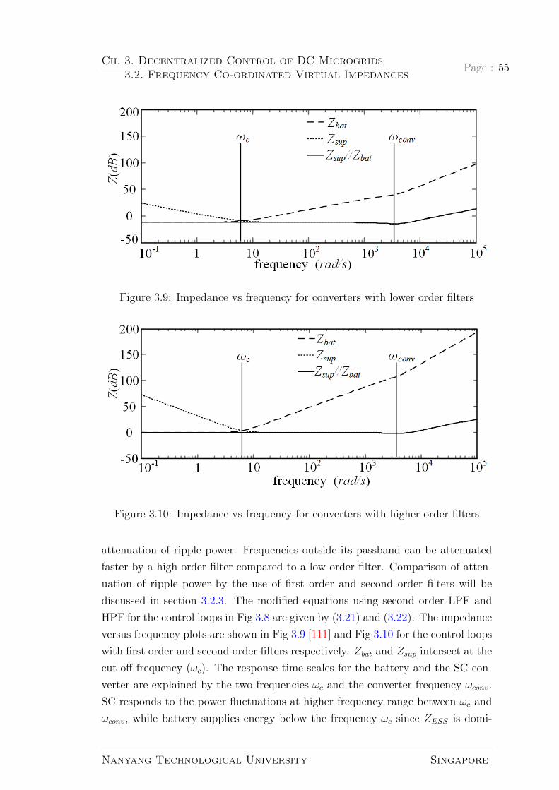
Ch. 3. Decentralized Control of DC Microgrids3.2. Frequency Co-ordinated Virtual Impedances
Page : 55
Figure 3.9: Impedance vs frequency for converters with lower order filters
Figure 3.10: Impedance vs frequency for converters with higher order filters
attenuation of ripple power. Frequencies outside its passband can be attenuatedfaster by a high order filter compared to a low order filter. Comparison of atten-uation of ripple power by the use of first order and second order filters will bediscussed in section 3.2.3. The modified equations using second order LPF andHPF for the control loops in Fig 3.8 are given by (3.21) and (3.22). The impedanceversus frequency plots are shown in Fig 3.9 [111] and Fig 3.10 for the control loopswith first order and second order filters respectively. Zbat and Zsup intersect at thecut-off frequency (ωc). The response time scales for the battery and the SC con-verter are explained by the two frequencies ωc and the converter frequency ωconv.SC responds to the power fluctuations at higher frequency range between ωc andωconv, while battery supplies energy below the frequency ωc since ZESS is domi-
Nanyang Technological University Singapore

Page : 56 Ch. 3. Decentralized Control of DC Microgrids3.2. Frequency Co-ordinated Virtual Impedances
nated by the battery. Thus, the HESS realizes complementary benefits of SC andbattery. Attenuation of a higher order filter outside the passband is sharper thana lower order filter which is equivalent to sharp increase in system impedance andcan be seen from the plot of (Z(dB)) vs frequency comparing Fig 3.10 and Fig 3.9.The corresponding values for cut-off and converter frequencies are ωc = 6.28rad/s
and ωconv = 6.28 ∗ 103rad/s respectively and the converter parameters are listedin Table 3.1.
Z ′bat(s) =Rdroop(ω
2c + 2ξωcs+ s2)
Gconv(s)ω2c
(3.21)
Z ′sup(s) =Rdroop(ω
2c + 2ξωcs+ s2)
Gconv(s)s2(3.22)
Where, ξ = 0.7 is the damping ratio.
3.2.2 Supercapacitor Voltage Restoration
Other significant issue of concern is the SC voltage restoration in the virtualimpedance configuration for the proposed HESS. After the transient charging/dischargingprocess the SC voltage will deviate from its nominal value. In such condition, fur-ther power fluctuations in the system may not be handled by SC. An additional SCvoltage control loop is needed in the HESS control system to address this problemas shown in Fig 3.11. The PI coefficient can be set such that the bandwidth ofZsup(s) is greater than the frequency response of the voltage restoration loop.
Figure 3.11: Supercapacitor voltage restoration loop
The law of power conservation ignoring power losses in the converter is expressedby (3.23). The linearized form of (3.23) with normal values of vdc and vsup can
Nanyang Technological University Singapore

Ch. 3. Decentralized Control of DC Microgrids3.2. Frequency Co-ordinated Virtual Impedances
Page : 57
be expressed as in (3.24). isup and vsup can be expressed as in (3.24) and (3.25)respectively and the modified converter control loop in accordance to them isobtained in Fig 3.12. The converter impedance is expressed in (3.26).
idcVdc = isupvsup (3.23)
isup = idcVdc0vsup0
(3.24)
vsup =−1
Csup
∫isup(t)dt (3.25)
Zsup =Vref (s)− Vdc(s)
idc(s)
=Rdroop(ωc + s)
Gconv(s)s
(1 +
Gconv(s)
sCsup
vdc0vsup0
Kps+Ki
s
)(3.26)
Where,
idc : current injected into the DC network;
isup: supercapacitor output current;
Vdc: DC bus voltage for HESS application;
vsup: supercapacitor output voltage;
Csup: supercapacitor value;
Cdc: DC network capacitor ;
Figure 3.12: Converter model for modified supercapacitor voltage restoration loop
Increase in Zsup(s) at frequencies below ωsup is seen upon adding this voltagerestoration control loop determined by PI controller parameters. ωsup should belesser than ωc for control agreement. Total impedance of HESS is not altered by
Nanyang Technological University Singapore

Page : 58 Ch. 3. Decentralized Control of DC Microgrids3.2. Frequency Co-ordinated Virtual Impedances
Table 3.2: Simulation and experimental parametersParameters Simulation value Experimental value
Nominal bus voltage (V ) 380 100Battery terminal voltage (V ) 190 48
Battery capacity (Ah) 150 150SC terminal voltage (V ) 190 50
SC capacity (µF ) 2200 2200Load1/ Load2 (Ω) 150/150 50/50
Figure 3.13: Simulation and experimental setup (a) Schematic layout (b) Experi-mental platform
the SC voltage restoration since the battery dominates the lower frequency range.
3.2.3 Simulation and Experimental Verification
A. Simulation results
A 380V DC microgrid was built in Piecewise Linear Electrical Circuit Simula-tion (PLECS) software. The control strategies analyzed above are realized throughsimulations. The schematic layout of simulation and experimental platform areshown in Fig 3.13(a). The PV, battery and SC converter parameters for controllerdesign discussed in sections above are listed in Table 3.1. The nominal systemparameters used during simulation and experiment are listed in Table 3.2. Theuse of first and second order LPF/HPF are tested for two operating conditions:a) step load change and b) sinusoidal disturbance on PV generation.
For the time scale co-ordination of HESS based on the concept of frequency coordi-nating virtual impedance, a step load increase at t = 1.5s is introduced in the sys-tem and the corresponding voltage and power waveform are shown in Fig 3.14(a).The step load decrease at t = 1.5s is depicted in Fig 3.14(b). It can be said
Nanyang Technological University Singapore

Ch. 3. Decentralized Control of DC Microgrids3.2. Frequency Co-ordinated Virtual Impedances
Page : 59
Figure 3.14: Waveforms for existing control loop during step load change (a) Stepload increase (b) Step load decrease
from the waveforms that during step load increase, the battery power increasesslowly, whereas, the SC almost spontaneously responds to the power fluctuations.Similarly, during step load decrease, the SC power decreases instantaneously inresponse to the power fluctuations in the system, but the battery power decreasesgradually. When the battery power decreases completely to respond to the loaddecrease in the system, the SC goes through voltage restoration process and theSC power rests at zero until the next transient condition takes place in the system.This is because of the fact that the battery converter consists of first order LPFand responds to the low frequency variations in bus voltage whereas SC utilizesfirst order HPF to respond to the high frequency variations in the system.
Fig 3.15(a) and Fig 3.15(b) show the system performance during the same stepload variation at t = 1.5s, however the virtual impedances are implemented withsecond order filters. The advantages of implementation of virtual impedances withsecond order LPF for battery converter and second order HPF for SC converterare discussed in section 3.2.1. The use of second order filters may induce voltage
Nanyang Technological University Singapore

Page : 60 Ch. 3. Decentralized Control of DC Microgrids3.2. Frequency Co-ordinated Virtual Impedances
Figure 3.15: Waveforms for proposed control loop during step load change (a)Step load increase (b) Step load decrease
and current oscillations during step load change in the system. By increasingthe cut-off frequency of battery converter in comparison with the control loopsimplemented for first order filters and by the increment in widely used value fordamping ratio of 0.707, the oscillation duration can be minimized.
The waveforms for sinusoidal disturbance on PV generation are shown in Fig 3.16.The generation demand mismatch is supplied by the HESS and the DC bus voltage(380V ) is regulated. Fig 3.17 shows the performance during the same sinusoidaldisturbance as that in Fig 3.16, but the virtual impedances are implemented withsecond order filters.
Since the attenuation of higher order filter outside the passband is sharper than thelower order, the ripple power has been diminished. It is proved by the comparisonof frequency spectrum in Fig 3.18 for two control strategies using first order andsecond order filters. The Fast Fourier Transform (FFT) diagram shows that themagnitude of ripple power in battery is decreased from 65V A in Fig 3.18(a) to11V A in Fig 3.18(b) by the use of second order filters. The decrease in ripple
Nanyang Technological University Singapore

Ch. 3. Decentralized Control of DC Microgrids3.2. Frequency Co-ordinated Virtual Impedances
Page : 61
Figure 3.16: Waveforms for existing control loop during change in PV generation
power decreases the stress on battery to increase its life time. In other words,the essence of showing FFT is to prove the better performance of second orderfilters over first order filters in attenuating different frequency components in time-domain caused by changing PV generation in the system. The correspondingtime-domain results are shown in Fig 3.16 and Fig 3.17. The role of SC is toco-ordinate with battery for providing high frequency oscillations caused by thedisturbance due to PV generation and hence the magnitude of SC power has alsobeen decreased in Fig 3.18(b).
B. Experimental results
A scaled down experimental setup for a 100V DC bus voltage to validate thecontrol strategies discussed above was constructed as shown in Fig 3.13(a). Theexperimental setup in Fig 3.13(b) shows the interfacing converters for PV, lead-
Nanyang Technological University Singapore

Page : 62 Ch. 3. Decentralized Control of DC Microgrids3.2. Frequency Co-ordinated Virtual Impedances
Figure 3.17: Change in PV generation for proposed control loop
Figure 3.18: FFT of the system (a) using first order filter (b) using second orderfilter
Nanyang Technological University Singapore

Ch. 3. Decentralized Control of DC Microgrids3.2. Frequency Co-ordinated Virtual Impedances
Page : 63
Figure 3.19: Experimental waveforms for existing control loop during step loadchange
Figure 3.20: Experimental waveforms with lower-order filters during transientprocess
acid battery and SC to the DC bus. The system was controlled by a dSPACEDS1103 PPC controller board. When step load is applied to the system at t =
500ms in Fig 3.19, the bus voltage is well regulated at Vdc = 100V . It can be seenthat the battery current slowly increases to provide the load demand whereas theSC current caters to the power fluctuation in the system during dynamic responsedue to load current step change. The sinusoidal fluctuation in PV generation and
Nanyang Technological University Singapore

Page : 64 Ch. 3. Decentralized Control of DC Microgrids3.3. Summary
Figure 3.21: Experimental waveforms with higher-order filters during transientprocess
the system response for it is depicted in Fig 3.20 utilizing lower order filters in thecontrol loop. It can be seen that the SC current responds to the PV fluctuationand maintains constant DC bus voltage and smoothens the load current, reducingthe stress on the battery. The DC bus and SC voltage in Fig 3.21 are controlledusing the control algorithm proposed which attenuates ripple power and noisyoutput better than that of the lower order filters.
3.3 Summary
In this chapter, the decentralized coordination control based upon frequency coor-dinated virtual impedance concept has been introduced for the power managementin DC microgrids. Such control strategy is superior to the conventional droop con-trol because of the relationship between diverse time scales and dynamic natureof various ESS and DGs. However, the co-ordination of multiple converters needadvanced power management in both steady-state and transient period. Thisdecentralized control approach has been applied to HESS consisting of lead-acidbattery and SC along with the PV in this thesis.
Bi-directional DC-DC converters act as a power electronic interface between thebattery/SC and the DC bus. Solar PV is interfaced to the DC bus by the meansof a DC-DC boost converter. The virtual output impedances are shaped into
Nanyang Technological University Singapore
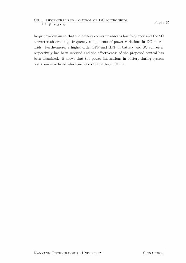
Ch. 3. Decentralized Control of DC Microgrids3.3. Summary
Page : 65
frequency-domain so that the battery converter absorbs low frequency and the SCconverter absorbs high frequency components of power variations in DC micro-grids. Furthermore, a higher order LPF and HPF in battery and SC converterrespectively has been inserted and the effectiveness of the proposed control hasbeen examined. It shows that the power fluctuations in battery during systemoperation is reduced which increases the battery lifetime.
Nanyang Technological University Singapore


Chapter 4
Interconnection of DC Microgrids
There will be embedded energystorage (at every layer of thegrid). It will be a collection ofmicrogrids.
—John Hewa, ARPA-E EnergySummit 2014
The application of DC microgrid for supplying power to DC loads along with sensi-tive loads ranging from electric vehicles, naval ships, space crafts, submarines, andindustrial power systems to consumer electronics, telecommunication systems andrural areas has risen due to its efficient nature and benefits of increased power sup-ply and higher reliability. Recent advancement includes the role of DC microgrid asa facilitator to integrate modernized electronic loads and alternative energy sourcesthat produce DC output power such as photovoltaic (PV) system, energy storages(e.g. chemical battery and supercapacitor) and fuel cell [59, 62, 98, 112, 113]. InChapter 3, the decentralized control of DC microgrid consisting of HESS hasbeen proposed and elaborated. This chapter will discuss about the interconnec-tion of multiple microgrids to improve reliability of the system as discussed insection 2.2.2 and will propose a decentralized control for two interconnected DCmicrogrids.
Although there is significant research for implementation of DC microgrids, lim-ited studies are done regarding modelling, stability analysis, and control of thesesystems, especially in the case that they are connected to the other microgrids tocreate DC microgrid clusters. Hierarchical model for interconnection of multipleDC microgrids based on the introduced hierarchical control loops in [95] are yet
67

Page : 68 Ch. 4. Interconnection of DC Microgrids
to be studied thoroughly. A hierarchical control strategy is recommended for DCmicrogrids with the control levels divided into: primary, secondary, and tertiarycontrol [114]. The primary control deals with the inner control loops and droopcontrol of the DC sources, which is strictly local. The droop control in this levelis a resistive virtual loop and provides the voltage reference to the inner controlloops. Nevertheless, for ESSs and RES, droop control is not always the preferredcontrol strategy where specified power is injected/absorbed to/from them [67].The droop control created deviations are removed with the secondary control bysetting the reference of primary control to maintain the bus voltage of DC micro-grids to acceptable levels. The tertiary control manages the current flow to/froman external DC source, which can be DC or AC microgrid, or a DC distributionsystem or a DC/AC converter connected to the main grid [67].
In the primary level, the ratings of the power converters give the measure ofdroop coefficient. Recently, various adaptive droop methods have been presentedin this issue [60,100,101,115]. For load sharing in multiterminal DC grids amongthe converters, an adaptive droop control scheme has been presented in [115]. Acontrol strategy with fuzzy logic for low voltage DC microgrid has been presentedin [116] to ensure low voltage deviation achieved by the modification of droopcoefficients with respect to state of charge (SoC) of every energy storage unit.A SoC-dependent function with discharging mode specifically for ESSs inside amicrogrid has been proposed in [100]. On the other hand, [60] has proposedtwo separate functions for both charging and discharging mode of the battery asper its SoC and capacity. Similarly, a double quadrant SoC based droop controlmethod has been presented in [101] that ensures SoC balancing and output poweradjustment in both charging and discharging modes.
An ESS can address the renewable intermittency in an islanded DC microgridenhancing the reliability and making the system more stable. In addition, theinterconnection of neighboring DC microgrids for exchange of power can furtherenhance the reliability [117, 118]. A control strategy for two interconnected DCmicrogrids operating at different voltage levels for rural grid has been proposedin [117]. A bidirectional DC-DC converter has been implemented in this controlto make the system reliable and energy efficient. Forming multiple DC microgridclusters by connecting multiple identical DC buses via tie-line also aids in makingthe system more efficient and reliable. The primary challenge in interconnectingDC microgrids is keeping the system stable, since the involvement of multipleparallel converters in a DC microgrid cluster make the system unstable. Despite
Nanyang Technological University Singapore

Ch. 4. Interconnection of DC Microgrids4.1. Interconnection of DC Microgrids Through Tie-line
Page : 69
DC microgrid being one of the most widely researched technologies in recent times,DC microgrid cluster is still a new concept yet to be explored. The interconnectionof DC microgrids still requires research regarding its operation and control.
This chapter proposes a decentralized control approach for controlling the bus volt-age of geographically dispersed microgrids in an allowable range that can managethe power flow via tie-line across the microgrid. Such approach being decentral-ized, is void of communication stress. The decentralized control is accompanied bymode change based operation. Thus, the distributed units can cope up with powerflow control and BVR providing autonomy to the interconnected microgrids. Incase of power deficit, power is injected/generated into/from the microgrid causedby demand-supply mismatch in a particular microgrid.
4.1 Interconnection of DCMicrogrids Through Tie-
line
Tie-line bias control is the mode of automatic generation control for interconnectedAC power systems. The functions of tie-line bias control can be classified as [119]:
a) It allows each area to respond to its local load changes.
b) It motivates each area in the cluster to respond to the system frequency change.
c) When an area is unable to supply its demand, unscheduled sharing occurs in theinterconnected system. In power systems, areas (microgrids) are interconnectedin order to share the generation and load.
Load frequency control (LFC) is employed in AC systems to respond to the fre-quency change of each area, in an interconnected system. In abnormal conditions,it also allows power flow through tie-line as inter-area support [120]. The terms“obligation” and “contribution” clarified by [119] for the tie-line bias control refer tothe functions (a), (b) and (c) listed above respectively. Various control strategieshave been proposed for LFC in AC systems [121,122]. Initially, centralized controlstrategy was used to address LFC. The limitation of such a control strategy wasthe computational burden due to communication links [121,122] in geographicallydispersed control areas leading to the evolution in the idea of decentralized con-trol. Decentralization of each cluster control plays a vital role in saving the costfor data communication and reducing the stress for network monitoring to achieve
Nanyang Technological University Singapore

Page : 70 Ch. 4. Interconnection of DC Microgrids4.1. Interconnection of DC Microgrids Through Tie-line
the dynamic operation of power systems [121]. The scope of this thesis does notcover the review of control strategies in AC systems.
Figure 4.1: Schematic layout of two DC microgrids interconnected with tie-line
The interconnection of DC microgrid clusters have been discussed in literaturereferences [11, 34, 67, 118, 123]. Hierarchical control has been proposed in [67,118, 123] to regulate the DC bus voltage and the efficiency of parallel connectedbatteries in each microgrid is improved by the use of adaptive droop based uponthe SoC information. Despite low bandwidth communication between neighboringnetwork for the estimated average voltage and SoC of batteries of cluster beingexamined using hardware in the loop simulation in this distributed approach,the issue of addressing geographically dispersed cluster still prevails. Tertiarycontrol for power sharing among microgrids in a cluster has been proposed byreference [11] where each microgrid has communication network communion tothe secondary control. Decentralized control approach in individual DC microgridthat modifies effective droop gain for good voltage regulation and load sharinghas been proposed by reference [34]. It exhibits better performance comparedto conventional droop control and hierarchical secondary control. However, theexamination of this control approach for interconnected microgrids focuses onlyon steady state performance and the tie-line power flow control is still centralized.Examination of source sharing has not been conducted. Though all these literaturehave significant contribution within the scope of the papers, the interconnectionof DC microgrids along with voltage regulation and power flow is still an openresearch. In DC microgrids, tie-line bias control is achieved by regulating the DCbus voltage to a specific level and provision of power flow between the control areaswhen an area is unable to respond to its demand during disturbance such thatthe “obligation” function (b) and “contribution” function of tie-line bias controlis achieved. The construction of an autonomous DC microgrid makes it able to
Nanyang Technological University Singapore

Ch. 4. Interconnection of DC Microgrids4.1. Interconnection of DC Microgrids Through Tie-line
Page : 71
respond to its local load change. Section 4.2 further explains these functions oftwo DC microgrids interconnected with tie-line.
Fig. 4.1 demonstrates the general configuration of using tie-line for interconnec-tion of two DC microgrids. Two neighboring DC microgrids, Microgrid 1 (MG1)and Microgrid 2 (MG2) in remote areas operating at the same voltage level havebeen considered in this thesis for the reliable power supply to the load. The in-terconnected microgrids consist of PV interfaced to each DC bus by means of aDC/DC boost converter. ESS in each microgrid is formed by a battery and abi-directional DC/DC converter. The circuit diagrams for interfacing convertersfor PV and ESS are depicted in Fig. 2.3(a) and Fig. 2.4(a) respectively.
The output voltage for conventional V-I droop control in terms of virtual outputimpedance can be expressed as (3.2) [95]. The term rdi characterizes the equivalentresistance of the converter, affiliated to the droop rate [111]. All the buses in theDC microgrid cluster obey the droop control in (3.2). Assuming there are n busesin the DC microgrid cluster and applying Kirchhoff’s current law, the currentflowing from ith bus to (n − 1) buses can be expressed as (4.1) [124]. The powerinjected through the tie-line from the ith bus can be represented by (4.2). Powerloss in the tie-line is expressed as (4.3). The power balance of the ith microgridduring tie-line power flow is represented by (4.4).
Idc,i(tie) =n∑
j=1j 6=i
Ytie,ij(Vdc,i − Vdc,j) (4.1)
Ptie,i = Vdc,iIdc,i(tie) (4.2)
∆Ptie = I2dc,i(tie)Ztie,ij (4.3)
PG,i − PD,i − Ptie,i = 0 (4.4)
Where, Vdc,i and Vdc,j are the respective DC bus voltages of ith and jth bus. Ytie,ij,Ztie,ij and Ptie,i represent the tie-line admittance, impedance and tie-line powerflow respectively. PG,i and PD,i denote total generation and demand on ith micro-grid respectively. Only two microgrids (MG1 and MG2) have been considered forthe study in this thesis. MG1 and MG2 shown in Fig. 4.1 operate autonomouslyunless there is power deficit in one of the microgrids.
Nanyang Technological University Singapore

Page : 72 Ch. 4. Interconnection of DC Microgrids4.2. Decentralized Control Strategies
4.2 Decentralized Control Strategies
4.2.1 Autonomous Decentralized Control
Most converters act as inherent current source converters [79]. Reference current(iref ) for the current control loop of the converter can be generated from (3.2).The transfer function (Gconv,i(s)) for the inner closed loop current control in theith converter of both microgrids has low pass characteristic with high bandwidthdue to fast switching [79] and is expressed as in (4.5), where τi represents timeconstant. This transfer function yields the bus current (ibusi) at the output [79].
Figure 4.2: Model of two interconnected microgrids with decentralized controlloop for bus voltage error minimization
Gconv,i(s) = 1/(τis+ 1) (4.5)
Vdc1 + Vdc2 = 2v∗MG (4.6)
2Vdc1 + vtie = 2v∗MG (4.7)
2Vdc2 − vtie = 2v∗MG (4.8)
Vdc1 = v∗MG −Rdp1io1 + (kp1 + ki1/s)×
(2v∗MG − 2Vdc1 + vtie) (4.9)
Vdc2 = v∗MG −Rdp2io2 + (kp2 + ki2/s)×
(2v∗MG − 2Vdc2 − vtie) (4.10)
vtie = ItieZtie (4.11)
Nanyang Technological University Singapore

Ch. 4. Interconnection of DC Microgrids4.2. Decentralized Control Strategies
Page : 73
The power flow of local terminal and the voltage deviation of the system areregulated by the converters involved in a DC microgrid. Converters are termed asterminal and bus regulating unit for power flow control as per their objective inorder to avoid control conflict.
Terminal regulating units are the renewable DGs performing on MPPT. Theirrole is to supply the power demand of the system and the power production isindependent of DC bus voltage variation. Unlike the PV converter, the batteryconverter in DC microgrid regulates the system voltage and nurtures power balanceof the system. Because of such an objective, it is termed as bus regulating unitand can be expressed as a Thevenin equivalent circuit with series impedance.The Thevenin voltage source refers to the voltage reference, the series impedancerefers to virtual impedance and the unit control operates in droop control mode[77]. Fig. 4.2 shows the control loops for battery converter in two interconnectedmicrogrids [125]. The control loop for voltage error signal generation of MG1 andMG2 buses is shown by the red dotted indication. These error signals representvoltage correction term Verr 1 and Verr 2 that restore the voltages at MG1 and MG2buses, which are added to the droop control unit of each microgrid. The principlebehind the bus voltage error minimization indicated in Fig. 4.2 is expressed asin (4.6) and can be elaborated as (4.7) and (4.8) for MG1 and MG2 respectively,where Vdc1, Vdc2 represent the DC bus voltages of MG1 and MG2 respectivelyand v∗MG signifies the microgrid reference voltage. Rdp1 and Rdp2 represent droopgains of battery converters in MG1 and MG2 respectively. Itie and Ztie stand fortie-line current and impedance, respectively. Cbus1, Cbus2 and RL1, RL2 in Fig. 4.2represent bus capacitors and load resistances for MG1 and MG2 respectively [118].The generalized expressions for the battery converter output voltages for MG1and MG2 can be simplified as in (4.9) and (4.10). The tie-line voltage drop vtie isexpressed as (4.11).
The tie-line power flow as calculated based upon (4.2) is dependent on the voltagedifference between two buses. The amount of tie-line power flow depends upon±5% change in the DC bus voltages of interconnected microgrids. The maximumtemperature of the conductor at which the line is designed to operate determinesthe rating of tie-line. There is always a time delay between a sudden change inthermal heating of conductors to the following temperature rise as the conductorshave significant thermal mass. A tie-line can withstand 115% overload for 10minutes without exceeding design temperature [126].
The DC current is uniformly distributed over the cross sectional area when passed
Nanyang Technological University Singapore

Page : 74 Ch. 4. Interconnection of DC Microgrids4.2. Decentralized Control Strategies
through a round cylindrical conductor and its resistance is given by (4.12) [127].The conductive material’s cross-sectional area (Ac), its resistivity (ρ) and length(l) determine the resistance of Ztie. The resistivity of a conductor and temperaturecoefficient depend upon the conductor material. No change in effective resistancedue to the skin effect and frequency change takes place in DC systems.
Ztie = ρl/Ac (4.12)
The control strategy proposed above is based upon (4.6) and is only applicableto minimize the bus voltage errors of two microgrids. Due to this limitation, thetopology for n bus microgrids connected with multiple tie-lines and the impact ofZtie variation in the system have not been considered in this thesis.
4.2.2 Mode Adaptive Decentralized Control
As mentioned in section 4.2.1, the converters in DC microgrids are categorized intoterminal regulating unit and bus regulating unit. Each converter is attributed to aparticular function, either to regulate power flow or to regulate the bus voltage inthe local terminal. This is done particularly to avoid control conflict in the system.The operation modes of renewable DGs and loads should be adjusted adaptivelyto counter their intermittent nature. For example, renewable generators like windand PV operate at MPPT when there is an increase in load demand but this is notthe case when the demand is low. To mitigate this issue, the operation modes ofDGs and ESS involved in a microgrid are designated depending upon the voltagelevel.
The DC bus voltage level as shown in Fig. 4.3 is grouped under three regions:nominal voltage, Vhigh and Vlow [79, 111]. Vhigh and Vlow are designated as ±5%
of the nominal DC bus voltage in order to indicate the operation modes desig-nation. The droop operation indicated in Fig. 4.3 is the BVR mode while thered lines indicate constant power (CP) mode. The constant power mode for PVrefers to the MPPT mode and that in battery refers to the charge/discharge incurrent control mode. For example, when power is interrupted in renewable DGlike PV or there is a surge in local consumption in MG1, the DC bus voltage atMG1 decreases. In addition, deviation in the bus voltage among two microgridsleads to power flow from MG2 to MG1. ESS of both microgrids, in such a case,operate in BVR mode. On the other hand, when the local load demand at one
Nanyang Technological University Singapore

Ch. 4. Interconnection of DC Microgrids4.2. Decentralized Control Strategies
Page : 75
Table4.1:
Ope
ration
mod
esan
dcorrespo
ndingvalues
during
diffe
rent
voltag
elevels
MG1
MG2
MG1/
MG2mod
esV
bus>
Vhigh
Vlow<
Vbus<
Vhigh
Vbus<
Vlow
Ptie
PG1<PL1
PG2<PL2
MPPT/M
PPT
--
Vbu
s1,V
bus2
-SoC
ES1≤LL
SoC
ES2≤LL
BRM/B
RM
PG1>PL1
PG2>PL2
BRM/B
RM
Vbu
s1,V
bus2
--
-SoC
ES1≥UL
SoC
ES2≥UL
Disch‡ /Disch‡
PG1>PL1
PG2>PL2
MPPT/M
PPT
-Vbu
s1,V
bus2
--
SoC
ES1≤LL
SoC
ES2≤LL
Ch/
Ch
PG1<PL1
PG2<PL2
MPPT/M
PPT
-Vbu
s1,V
bus2
--
SoC
ES1≥UL
SoC
ES2≥UL
Disch/D
isch
PG1>PL1
PG2<PL2
MPPT/M
PPT
-Vbu
s1,V
bus2
--
SoC
ES1≤LL
SoC
ES2≥UL
ch/D
isch
PG1<PL1
PG2>PL2
MPPT/M
PPT
-Vbu
s1,V
bus2
--
SoC
ES1≥UL
SoC
ES2≤LL
Disch/ch
PG1>PL1
PG2<PL2
BRM/M
PPT
Vbu
s1-
Vbu
s2(4.1)&
(4.2)
SoC
ES1≥UL
SoC
ES2≤LL
Disch‡ /ch
PG1<PL1
PG2>PL2
MPPT/B
RM
Vbu
s2-
Vbu
s1(4.1)&
(4.2)
SoC
ES1≤LL
SoC
ES2≥UL
ch/D
isch‡
‡deno
tesdischa
rgeat
man
ufacturer’sspecification
incurrentcontrolm
ode
LLan
dULdeno
teSo
Clower
andup
perlim
itof
ESrespectively
Nanyang Technological University Singapore

Page : 76 Ch. 4. Interconnection of DC Microgrids4.2. Decentralized Control Strategies
Figure 4.3: Graphical representation of mode adaptive control
microgrid or both microgrids is less than the total generation in each microgrid,the DC bus voltage increases. The terminal regulating unit such as PV shouldchange its operation from MPPT to BVR mode to retain this increment to thenominal value. Likewise, the battery converter shifts to current control mode andits charge/discharge is determined by the reference current provided to the batteryconverter (i.e. rated charging current provided by the manufacturer). When thelocal demand is sufficiently met by the local generation, no mode change is ob-served. The terminal regulating unit operates on MPPT mode and bus regulatingunit on BVR mode in this case. Thus, in order to maintain the DC bus voltage,the distributed generation units in two microgrids switch their operation modes,as per the change in demand-supply.
If the capacity of an energy storage and the generation units in both microgridsare not able to cater local load demand, load curtailment must be opted. The firstrow of Table 4.1 provides the details on the generation and energy storage statusof such a case. As the bus voltage of the DC microgrid decreases during excessivedemand, the flow of power takes place via tie-line caused by the difference in thebus voltages of two microgrids within the capacity of the tie-line.
The decentralized control proposed in this thesis is preferred to the centralizedand distributed control for interconnecting DC microgrids since it nullifies the
Nanyang Technological University Singapore

Ch. 4. Interconnection of DC Microgrids4.2. Decentralized Control Strategies
Page : 77
Table 4.2: Simulation and experimental parametersParameters Simulation value Experimental value
Nominal bus voltage (V ) 380 48Battery terminal voltage (V ) 190 24
Battery capacity (Ah) 150 7Load1/ Load2 (Ω) 30/30 120/120
communication stress of geographically distant areas. Moreover, this approachto control is feasible and simple in nature. In addition, the decentralized modeadaptive control for the power management of DC microgrids adjusts the operationmodes of RES and ESS as discussed earlier. Such self-disciplined regulationsof converters in microgrids without communication links make the system morereliable and flexible.
4.2.3 Simulation and Experimental Verification
A. Simulation results
To verify the aforementioned control strategies, two microgrids consisting of PVand battery are built in PLECS environment. The DC bus voltage is set to be380V . The use of decentralized control is tested for two types of load: a) constantpower load (CPL) and b) a step load change in each microgrid to examine whetherthe load change is self-sustained by the respective microgrid.
The control loop proposed in Fig. 4.2 is implemented to examine the essence of thecontrol loop as shown in Fig. 4.4. The voltage difference (∆V ) of MG1 and MG2 is0.724V before t = 4s and due to the CPL of 1000W and 1500W connected to MG1and MG2 respectively, there is a flow of power (Ptie = 249.8W ). Itie signifies thecorresponding tie-line current in Fig. 4.4. This phenomenon proves the necessityof control loop for bus voltage error minimization in Fig. 4.2 for the autonomousoperation of each microgrid when the local supply is sufficient to cater the localdemand. After the activation of control loop at t = 4s for minimizing the errorin bus voltage, bus voltages are maintained at 380V to reduce the tie-line powerflow to zero, thus, achieving the function b) discussed in section 4.1.
A step load is introduced in the system with the proposed decentralized controlat t = 5s and 10s in MG1 and MG2 respectively in Fig. 4.5. From the waveforms,it can be seen that at steady state, both the DC bus voltages of MG1 (Vdc1) andMG2 (Vdc2) are 380V and hence the tie-line current is zero. At t = 5s, there is a
Nanyang Technological University Singapore

Page : 78 Ch. 4. Interconnection of DC Microgrids4.2. Decentralized Control Strategies
Figure 4.4: Performance of proposed decentralized control method
step load change in MG1 which causes the power demand to increase. Since PVat both microgrids is in MPPT mode, the battery responds to the power deficitcaused by load change. The response of battery to the load change regulates thebus voltage fluctuation and it is maintained to be 380V , making tie-line currentflow to zero. Similarly, at t = 10s, a step load is applied to MG2 and it is ableto regulate the bus voltage fluctuation and supply power to maintain generation-demand balance. This shows that the microgrid is able to cater its local demandand hence the “obligation” function a) of tie-line bias control discussed in section4.1 is achieved.
The logic behind the relationship between bus voltage increment/decrement dueto the change in generation/demand is provided in section 4.2.2. For the sake ofbrevity, CPL of 200W that is less than MPPT generation of PV is provided inboth microgrids. The changes in MG1 have been observed to validate mode changebased operation setting Vhigh as 390V and Vlow as 370V and the bus voltages ofMG1 and MG2 along with tie-line current flow are shown in Fig. 4.6. A DC bussignal of 395V is provided at t = 0s in the control logic, PV at this momentoperates at BVR (Fig. 4.7) and battery is charged with manufacturer’s chargingcurrent reference. At 5s, the DC bus voltage is ramped from 395V → 380V (slope−5 per second). When the control logic finds the moment of 390V at t = 6s inFig. 4.6, the PV and battery converters are changed to MPPT (Fig. 4.7) and BVRmode respectively. Similarly, a ramped DC signal from 380V → 365V has been
Nanyang Technological University Singapore

Ch. 4. Interconnection of DC Microgrids4.2. Decentralized Control Strategies
Page : 79
Figure 4.5: Waveforms for DC bus voltages and battery power in MG1 and MG2
observed in simulation. The power generation, state of ESS and mode changes inboth microgrids has been tabulated in Table 4.1. The first two rows in Table 4.1indicate two extreme scenarios of operation when load and generation curtailmentrespectively should be executed. The subscripts G, L and ES denote generation,load and energy storage (battery) for the respective microgrid. The tie-line currentwhich is the “contribution” discussed in previous section, can be calculated using(4.1) and its maximum value can be obtained by substituting Vhigh and Vlow in placeof bus voltages of ith and jth microgrid in (4.1). The nominal system parametersused during simulation and experiment are listed in Table 4.2.
B. Experimental results
Nanyang Technological University Singapore

Page : 80 Ch. 4. Interconnection of DC Microgrids4.2. Decentralized Control Strategies
Figure 4.6: DC bus voltages and tie-line current during mode change
Figure 4.7: PV power at MG1 and MG2 during mode change
In this section, a prototype of a droop controlled two interconnected DC microgridswith implementation of control strategy discussed in section 4.2 is established. Theschematic layout of experimental platform is shown in Fig. 4.8 and the nominalsystem parameters are listed in Table 4.2. The DC bus voltages of the two mi-
Nanyang Technological University Singapore

Ch. 4. Interconnection of DC Microgrids4.2. Decentralized Control Strategies
Page : 81
crogrids are set at 48V , which is generally implemented in telecommunicationapplications. Each microgrid consists of PV and lead acid battery interfaced tothe DC bus by means of a DC-DC boost converter and a bi-directional DC-DCconverter respectively. The system was controlled by a dSPACE DS1103 PPCcontroller board. Four experimental cases have been carried out to validate theinterconnection of DC microgrids through tie-line.
Figure 4.8: Schematic layout of experimental platform
Figure 4.9: Step load change in MG2
Voltage stability test by step load change in the system
This test demonstrates the self-sustained operation of DC microgrids connectedthrough tie-line when the generation of a microgrid is sufficient to supply thedemand. The battery currents and DC bus voltages of both microgrids duringstep load change at t = 80ms in MG2 are shown in Fig. 4.9. The corresponding
Nanyang Technological University Singapore

Page : 82 Ch. 4. Interconnection of DC Microgrids4.2. Decentralized Control Strategies
battery of MG2 (Ibat2) responds to the demand while the battery current at MG1(Ibat1) remains unchanged. It can be seen from Fig. 4.9 that the battery is chargingbefore step load change in the system since the generation is sufficient to supplythe system demand. After step load change, the load power demand of 38.4W
has been catered by the battery in MG2. Generation curtailment by mode changebased operation has not been examined in this section and is explained in "Modetransition test" below in this Chapter. Fig. 4.10 shows the tie-line current flowduring step load change in MG2 at t = 80ms. The zero tie-line current provesthat both microgrids are able to cater to the local demand autonomously. The DCbus voltages of 48V for both microgrids are shown in both Fig. 4.9 and Fig. 4.10and are well regulated.
Figure 4.10: Tie-line current during step load change in MG2
Voltage stability test by generation fluctuation
This experiment aims to verify the voltage stability under proposed control scheme.To emulate the generation fluctuation, an oscillating current is injected by the PVconverter in MG1. The bus voltages and PV converter currents for MG1 andMG2 are demonstrated in Fig. 4.11 and the corresponding battery currents forMG1 and MG2 along with bus voltages are displayed in Fig. 4.12. It can be seenfrom the waveforms that the bus voltage in MG1 is well regulated since the powerfluctuation from PV is compensated by the battery in MG1. The PV and batterywaveforms in MG2 are unaffected by this variation. The generation from PVsupplies the load power of 19.2W in MG2, while the battery charges with excess
Nanyang Technological University Singapore

Ch. 4. Interconnection of DC Microgrids4.2. Decentralized Control Strategies
Page : 83
Figure 4.11: Sinusoidal fluctuation in PV generation in MG1
Figure 4.12: Bus voltages and battery current during sinusoidal fluctuation in PVgeneration in MG1
generation maintaining constant DC bus voltage of 48V .
Mode transition test
In this case, MG1 initially operates in generation dominating mode PV beingat MPPT mode of operation. The battery is being charged at this time sincethe renewable generation is sufficient to cater to the load demand. When thebattery reaches the saturation point, the bus voltage rises. In such a case, the
Nanyang Technological University Singapore

Page : 84 Ch. 4. Interconnection of DC Microgrids4.2. Decentralized Control Strategies
Figure 4.13: Test for mode change based operation in MG1
Figure 4.14: Examination of tie-line current flow from MG1 to MG2
PV generation working on MPPT is supposed to switch to bus regulation modein order to curtail the generation. A mode change logic is provided in MG1 att = 100ms and is demonstrated in Fig. 4.13. The waveforms show that the PVunit goes to bus regulation mode while the battery discharges for the system losses.The control strategy is effective to regulate the bus voltages.
Tie-line power flow test
The change in the bus voltage is realized at MG1, leading to tie-line current flow
Nanyang Technological University Singapore

Ch. 4. Interconnection of DC Microgrids4.3. Summary
Page : 85
Figure 4.15: Bus voltages and battery current during tie-line current flow in MG2
to MG2 as expressed in (4.1). Both MG1 and MG2 have a load of 60Ω. It canbe seen from Fig. 4.14 that the tie-line current of 800mA flows from the highervoltage (MG1) to the lower voltage level (MG2). MG1 provides tie-line currentwhile supplying local demand whereas MG2 supplies local demand only. The busvoltages and battery currents of both microgrids are shown in Fig. 4.15.
4.3 Summary
In this chapter, the interconnection of two DC microgrids through tie-line isimplemented for enhancing the reliability and source sharing during power sur-plus/deficit in a microgrid. A decentralized control has been proposed focusing ongeographically dispersed clusters to provide resilience to the system. The controlstrategy acknowledges the BVR in each DC microgrid. The proposed control strat-egy has been facilitated by mode adaptive control that designates the operationmodes of different DG units to venture autonomous operation in microgrids. As aresult, both the system reliability and flexibility could be enhanced. System per-formance is verified through simulation and experimental results. The objectiveof proposed control strategy can be summarized as follows:
• The use of decentralized control approach eliminates the communicationstress when the microgrid control areas are geographically dispersed.
Nanyang Technological University Singapore

Page : 86 Ch. 4. Interconnection of DC Microgrids4.3. Summary
• The interconnection of microgrids with tie-line facilitates the generationsharing when one of the microgrids has supply-demand mismatch.
• Each microgrid can operate autonomously when there is no deficit in supplyand has the provision of generation curtailment during supply surplus.
• The dynamic operation during load/source variation in microgrids has beenexamined to maintain the bus voltage.
Nanyang Technological University Singapore

Chapter 5
Bipolar-Type DC Microgrids
People are beginning to under-stand that they need their ownonsite capabilities to island them-selves from the grid. That’s be-cause the grid’s external vulnera-bilities will continue to be a prob-lem until we do have substan-tial amounts of distributed gen-eration.
—Jon Wellinghoff, 2015
After a century long repression of DC power by its AC opponent, DC power deliv-ery has regained popularity in recent times, the key reason being the developmentof HVDC transmission systems. The controllability and power capacity of DCpower delivery has made it advantageous over the AC transmission lines [128–130].This trend has now found its scope from transmission to the distribution system,which is the bottom part of the electrical supply chains [79]. It might be widelyused to increase the power quality and capacity by providing a greater resilienceagainst irregular loads and power surge, and to facilitate the penetration of re-newable DGs [33, 79, 111, 131]. In Chapter 3 and Chapter 4, the decentralizedcontrol of DC microgrids with unipolar DC bus has been proposed. One of thedisadvantages of DC microgrids with unipolar DC bus as discussed in section 2.2.1is the necessity of higher precision in circuit and control parameter design. Onthe other hand, consumers have no redundancy on supply voltage level since theyhave to be powered with only one bus at a specific voltage level. This chapterwill discuss about the bipolar-type DC microgrids to provide DGs and loads with
87

Page : 88 Ch. 5. Bipolar-Type DC Microgrids
different voltage levels and serve as an option for alternative voltage levels [130].
The DC distribution technologies can accommodate the lowest voltage level dueto their relative maturity of Low-Voltage DC (LVDC) electric apparatuses thatinclude DC circuit breakers and power electronic converters. Initially, primary DCdistribution systems with a rated voltage of 48V are deployed for communicationpower supplies [132] followed by the transportation power systems alike in shipsand electric aircrafts. The DC voltage level is scaled up to several hundred volts tohandle the extended power range [76,133]. The latest initiatives in DC distributionare reaching for electric vehicle charging stations and residential applications ingreen buildings [134]. The advantages of DC distribution are highlighted in section1.1.
On the flip side, the practical application of DC microgrids adheres to the followinglimitations [64]:
a) DC microgrid requires private DC distribution lines.
b) The absence of zero cross point of voltage makes the protection in DC systemscomplicated in comparison to the AC system.
Efficient and high-quality power is essential for the customers in commercial aswell as industrial sectors like semiconductor factories, banks and hospitals sincethe downtime related to voltage sag banks, hospitals or blackout is a matter ofgreat concern [64].
To make the power supply efficient as well as to increase its quality, “a low-voltagebipolar-type DC microgrid” has been proposed in [135]. This system distributesthe DC power through three-wire lines, which is then converted to the requiredAC or DC voltages by the help of load-side converters. In case of voltage sag orblackout in the utility grid, the DC microgrid can provide high-quality power in astable manner, whereas in the case of AC microgrids, inverters of the DGs shouldbe tripped unless they have the fault-ride-through capability [64].
Higher reliability, ability of power transfer in case of line failure, reduced lossesduring decreased levels of current and increased energy transmission capacity makethe bipolar transmission lines applied in HVDC advantageous over the unipolarsystems [136].
A typical low voltage bipolar-type DC grid is shown in Fig 5.1 [130]. The MediumVoltage AC (MVAC) and LVDC grid are interfaced by a distribution transformerand a distribution AC/DC converter. To provide two alternative voltage levels
Nanyang Technological University Singapore

Ch. 5. Bipolar-Type DC Microgrids Page : 89
Figure 5.1: A typical low voltage bipolar-type DC grid
for DGs and loads with different voltage or power scales, a bipolar configurationcan be adopted for the DC grid similar to the three-phase structure in AC powersystems [64, 136]. Each pole, positive or negative, is treated as a single-phaseAC system. In addition, the voltage across the positive and negative terminalsis analogous to the line-line voltage in AC systems. The three-wire bipolar DCmicrogrid consists of local loads on the upper/positive and the lower/negativeterminals connected to the neutral terminal respectively as shown in Fig. 5.1. Theflexibility lies in the connection of heavy loads to the upper and lower terminalsachieving twice the voltage of positive/negative half [137]. In case of failure of onewire, the system continues to supply power through the remaining two wires.
The bipolar-type DC microgrids bring some challenges along with the above men-tioned advantages. Because of different loadings in the upper and lower terminals,the terminal voltage fluctuates from the nominal value resulting in an unbalancedbipolar-type DC microgrid. To mitigate such a problem of power quality andsystem stability due to the asymmetrical power distribution in the bipolar-typeDC microgrid, a comprehensive investigation is required for both the convertertopology and the operation control strategy [130].
Distribution converter topologies for bipolar-type DC microgrids
The distribution converter plays a key role in the formation of bipolar-type LVDC
Nanyang Technological University Singapore

Page : 90 Ch. 5. Bipolar-Type DC Microgrids
distribution [130]. One of the ways to obtain the bipolar DC output is the utiliza-tion of two cascaded Voltage Source Converter (VSC) as depicted in Fig 5.2 [130].The disadvantage of such a topology is the requirement of two separated con-verters along with the two isolated windings for the distribution transformer thatincreases the size and cost of the system. Another way to achieve the bipolar DC
Figure 5.2: Two cascaded VSC for bipolar output
Figure 5.3: Single VSC with neutral line current regulation for bipolar output
output using single VSC is to connect the neutral line of distribution transformer
Nanyang Technological University Singapore

Ch. 5. Bipolar-Type DC MicrogridsDecentralized Control
Page : 91
to the midpoint of DC output capacitors as shown in Fig 5.3 [130]. The DC volt-age is balanced by regulating the current in the neutral line. However, the DCcomponent of the neutral line current might cause transformer saturation.
The neutral line DC current can be prevented by using an extra half-bridge circuitfor voltage balancing as shown in Fig 5.4 by redistributing the currents [130]. Ithas a more simplified structure than the topology shown in Fig 5.2 and is moretolerant to unbalanced load currents than the topology shown in Fig 5.3 [130].Such a voltage balancer has been reported in [65,130].
Figure 5.4: Extra half-bridge circuit for achieving bipolar output
5.1 Decentralized Control of Bipolar-Type DCMi-
crogrids
The asymmetric distribution of loads at the upper and lower terminals is a majorchallenge of a bipolar type DC microgrid. It results in the fluctuation of terminalvoltage from the nominal value making the DC microgrid unbalanced. In orderto mitigate the issue of voltage imbalance, [64] and [138] have proposed a central-ized voltage balancer. The disadvantage of such a solution is that the failure of
Nanyang Technological University Singapore

Page : 92 Ch. 5. Bipolar-Type DC MicrogridsDecentralized Control
the central voltage balancer deteriorates the system functionality. A decentralizedcontrol for voltage balancing in a bidirectional DC/DC boost converter is pro-posed in reference [137], however, the topology proposed consists of extra diodesthat account for the additional system losses. Moreover, it does not discuss thepower contribution to the positive and negative halves by the use of multiple busregulating units in the system. A topology integrating a Single-Ended PrimaryConverter (SEPIC) and a Cuk converter is proposed in reference [139]. Such anintegration increases the number of passive elements in the circuit in the presenceof multiple DERs interconnected to the microgrid, which may increase the systemlosses. Therefore, the control of parallel converters which interface the DERs andthe topology of the converters along with the voltage balancer plays a vital rolein the formation of an efficient bipolar-type DC microgrid.
Several types of droop control which supplant the centralized master slave controlhave been proposed in different literature [62,77,78,94,95] for the parallel operationof converters that are applied in the unipolar DC microgrids and can be imple-mented in the bipolar-type DC microgrids. Since the droop control is decentral-ized, it has many advantages such as plug and play capability; no communicationlink is required between the converters, simplicity and easy maintenance.
An improved bipolar-type DC microgrid is proposed in this chapter where decen-tralized control for parallel converters interfacing the DERs is implemented. Theproposed decentralized voltage balancing control supersedes the centralized volt-age balancer in terms of the utilization of communication links and enhances thesystem reliability. The decentralized control for boost converter control and thewidely implemented centralized control for voltage balancing circuit is explainedin this section . Such a control can be adopted in the bipolar-type DC microgridconsisting of multiple energy storages. One of the challenges of control conflictin the implementation of decentralized voltage balancer concept is mitigated bythe means of droop control and will be discussed in section 5.2. An experimentalprototype of the two-source bipolar-type DC microgrid has been built to validateits performance and is discussed in section 5.3.
System configuration and droop scheme
The topology and control scheme for two ESSs parallely interfaced to the commonbipolar DC bus are shown in Fig. 5.5. The circuit consists of two control loops,namely, boost converter control and voltage balancing control. The basic droopscheme mentioned in literature for the interfacing boost converters of two energy
Nanyang Technological University Singapore

Ch. 5. Bipolar-Type DC MicrogridsDecentralized Control
Page : 93
storages in Fig. 5.5 is expressed in (3.2) [95]. The droop coefficient or the virtualresistance Rdroopi is designed as expressed in (3.3). The implementation of virtualresistance will ensure proportional power sharing between the ESSs as long as thevirtual resistances are tuned well according to (3.3). The limitations associatedwith the droop control implemented in the DC microgrid due to the tuning ofvirtual resistance are DC bus voltage deviation and current sharing accuracy.Several literature have proposed/reviewed valid solutions to these problems in[34, 62, 77, 78, 81, 92, 94, 95, 102]. The expression for droop control implemented inthe boost converter control for the bipolar configuration as shown in Fig. 5.5 isgiven by (5.1).
Figure 5.5: Power circuit for a bipolar DC microgrid with control block diagram
Vref − IoiRdroopi = V +i + V −i (5.1)
Where, V +i and V −i are the capacitor voltages of upper half and lower half of the
Nanyang Technological University Singapore

Page : 94 Ch. 5. Bipolar-Type DC Microgrids5.2. Decentralized Voltage Balancing Control
bipolar configuration of ith converter shown in Fig. 5.5. Rdroopi denotes the virtualresistance of ith converter in a bipolar-type DC microgrid for the decentralizedboost converter control loop as shown in Fig. 5.5.
The interfacing converters for the DERs involved in DC microgrids are classifiedas terminal and bus regulating units in order to avoid control conflict. DGs serv-ing as the constant power source working at MPPT such as solar PV and windare categorized as terminal regulating unit while others like ESS are classified asbus regulating units [77,81]. The terminal and bus regulating units in a microgridare discussed in section 2.3.3 and section 4.2.1. In this section, two bus regulat-ing units implementing droop control for power sharing are analyzed to achievedecentralized voltage balancing control for the bipolar-type DC microgrid.
5.2 Decentralized Voltage Balancing Control
Essence of voltage balancing and control
The challenge in the bipolar-type DC microgrids lies on the asymmetrical oper-ation due to the load distribution on its positive and negative halves. Such anoperation might cause voltage imbalance in the system and lead to poor powerquality and system instability. To mitigate such a problem, voltage balancing con-trol should be implemented with thorough investigation of the converter topologyand its operation control. Several literature have proposed a central voltage bal-ancer for voltage balancing control in DC microgrids as shown in Fig. 5.5 and itsdisadvantages have been indicated in previous section. The focus of this chapter isto propose a bipolar-type DC microgrid with a decentralized control which has thecapability of preserving the functionality of microgrid by ride through the (evenif there is) malfunction in a central voltage balancer.
A simple way to implement decentralized control is to generate the inductor cur-rent reference from the differences in V +
i and V −i using conventional minimizationof error signal based upon a proportional-integral (PI) controller between the up-per and lower half of the bipolar configuration of ESS. The inner current controlloop generates the duty cycle for switches Si3 and Si4 tracking the referenceinductor current.
The problem with such decentralized control implementation arises when there aretwo bus regulating units such as two ESSs in Fig. 5.5 due to control conflict. This
Nanyang Technological University Singapore

Ch. 5. Bipolar-Type DC Microgrids5.2. Decentralized Voltage Balancing Control
Page : 95
Figure 5.6: Voltage and current waveforms to show control conflict
is because of the fact that multiple sources and storages with same priority withinthe system may not operate in the same voltage band to share load according totheir ratings [78]. For instance, the decentralized voltage balancing achieved bythe PI-based control may have different voltage offsets in practice and the inductorcurrent references generated for the two ESSs increase/decrease infinitely as shownin Fig. 5.6 This is due to the integral part of PI-based voltage controller used togenerate the current reference. ∆V denotes the voltage difference between upperand lower terminals of the DC bus and IL_ba1 and IL_ba2 are the inductor currentsof ESS1 and ESS2 in the voltage balancing circuit in Fig. 5.5. Different voltageoffsets are added to V −1 and V −2 respectively in the simulation result of Fig. 5.6 tohighlight the problem which exists in practical scenarios.
Proposed control strategy
The circuit diagram for a half-bridge voltage balancer, consisting of two IGBTs,two capacitors and a reactor is shown in Fig. 5.7 taking ESS1 in Fig. 5.5 as anexample. Inductor L_bai in the diagram performs the voltage balancing role only.The DC bus is segregated into a three-wire system consisting of positive, neutraland negative lines. If the upper and lower halves are equally loaded, there willbe no current flowing through the inductor L_bai. The voltage fluctuation in thecircuit occurs when there is an unbalanced load in the positive and negative halvesof the balancing circuit. The advantage of implementing such a topology reducesthe ohmic power loss by half in comparison to a two-wire DC bus based system.However, the power sharing achieved does not show good result and the problemshown in Fig. 5.6 and discussed above exists.
Nanyang Technological University Singapore
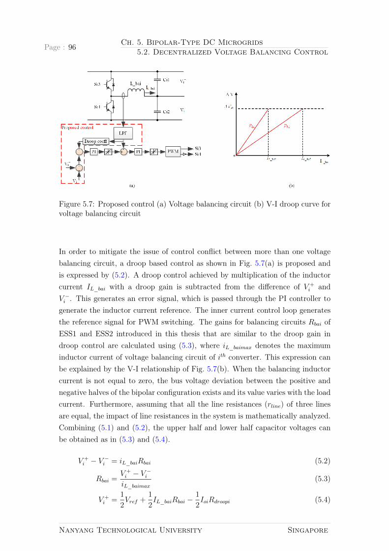
Page : 96 Ch. 5. Bipolar-Type DC Microgrids5.2. Decentralized Voltage Balancing Control
Figure 5.7: Proposed control (a) Voltage balancing circuit (b) V-I droop curve forvoltage balancing circuit
In order to mitigate the issue of control conflict between more than one voltagebalancing circuit, a droop based control as shown in Fig. 5.7(a) is proposed andis expressed by (5.2). A droop control achieved by multiplication of the inductorcurrent IL_bai with a droop gain is subtracted from the difference of V +
i andV −i . This generates an error signal, which is passed through the PI controller togenerate the inductor current reference. The inner current control loop generatesthe reference signal for PWM switching. The gains for balancing circuits Rbai ofESS1 and ESS2 introduced in this thesis that are similar to the droop gain indroop control are calculated using (5.3), where iL_baimax denotes the maximuminductor current of voltage balancing circuit of ith converter. This expression canbe explained by the V-I relationship of Fig. 5.7(b). When the balancing inductorcurrent is not equal to zero, the bus voltage deviation between the positive andnegative halves of the bipolar configuration exists and its value varies with the loadcurrent. Furthermore, assuming that all the line resistances (rline) of three linesare equal, the impact of line resistances in the system is mathematically analyzed.Combining (5.1) and (5.2), the upper half and lower half capacitor voltages canbe obtained as in (5.3) and (5.4).
V +i − V −i = iL_baiRbai (5.2)
Rbai =V +i − V −iiL_baimax
(5.3)
V +i =
1
2Vref +
1
2IL_baiRbai −
1
2IoiRdroopi (5.4)
Nanyang Technological University Singapore
Ch. 5. Bipolar-Type DC Microgrids5.2. Decentralized Voltage Balancing Control
Page : 97
V −i =1
2Vref −
1
2IL_baiRbai −
1
2IoiRdroopi (5.5)
According to Kirchhoff’s Current Law (KCL),
IL_bai = I−oi − Ioi (5.6)
The upper half bus voltage V + for the two converters can be expressed as (5.7),where i = 1, 2.
V + = V +i − Ioirline + IL_bairline (5.7)
=1
2Vref − Ioi(
1
2Rdroopi +
1
2Rbai + 2rline) + I−oi(
1
2Rbai + rline)
Putting the value of i which indicates the converter number and equating theterms in (5.7), (5.8) is obtained.
Io1
(1
2Rdroop1 +
1
2Rba1 + 2rline
)− I−o1
(1
2Rba1 + rline
)= Io2(
1
2Rdroop2 +
1
2Rba2 + 2rline)− I−o2(
1
2Rba2 + rline) (5.8)
Similarly, equating the lower half bus voltages (V −) for two converters as in (5.7),(5.9) can be obtained.
Io1
(1
2Rba1 −
1
2Rdroop1 + rline
)− I−o1
(1
2Rba1 + 2rline
)= Io2
(1
2Rba2 −
1
2Rdroop2 + rline
)− I−o2
(1
2Rba2 + 2rline
)(5.9)
Where,
Io1: positive-half current of the ESS1 in a bipolar-type DC microgrid;
Io2: positive-half current of the ESS2 in a bipolar-type DC microgrid;
I−o1: negative-half current of the ESS1 in a bipolar-type DC microgrid;
I−o2: negative-half current of the ESS2 in a bipolar-type DC microgrid;
Usually in DC MGs, for high power applications and small systems where trans-mission line is short, the line resistance has only small value in comparison withlarger Rdroopi that is selected for the system [94]. The inverse proportional rela-tionship between the output currents and virtual resistances for power sharing can
Nanyang Technological University Singapore

Page : 98 Ch. 5. Bipolar-Type DC Microgrids5.3. Simulation and Experimental Verification
be achieved only when Rdroopi >> rline. So, ignoring rline in (5.8) and (5.9) willyield,
Io1
(1
2Rdroop1 +
1
2Rba1
)− I−o1
(1
2Rba1
)= Io2
(1
2Rdroop2 +
1
2Rba2
)− I−o2
(1
2Rba2
)(5.10)
Io1
(1
2Rba1 −
1
2Rdroop1
)− I−o1
(1
2Rba1
)= Io2
(1
2Rba2 −
1
2Rdroop2
)− I−o2
(1
2Rba2
)(5.11)
Subtracting and adding (5.10) and (5.11) respectively, (5.12) and (5.13) can beobtained.
Io1Rdroop1 = Io2Rdroop2 (5.12)
Rba1(Io1 − I−o1) = Rba2(Io2 − I−o2) (5.13)
Substitution of (5.6) in (5.13) will yield (5.14),
IL_ba1Rba1 = IL_ba2Rba2 (5.14)
From (5.12) and (5.14), it can be said that the loads at positive and negativehalves are shared according to the designated droop gains even though the loadsat each halves are different, provided that Rdroopi >> rline.
Table 5.1: Simulation and experimental parametersParameters Simulation value Experimental value
Nominal bus voltage (V ) 760 100L_boost1, L_boost2, L_ba1, L_ba2 (mH) 2 5
C11, C12, C21, C22 (µF ) 4700 470Load1/Load2[positive half] (Ω) 50/100 50/25Load1/Load2[negative half] (Ω) 100/100 50/50
Switching frequency (kHz) 10 20
5.3 Simulation and Experimental Verification
Simulation results
Nanyang Technological University Singapore

Ch. 5. Bipolar-Type DC Microgrids5.3. Simulation and Experimental Verification
Page : 99
Figure 5.8: Voltage and current waveforms for same droop gain
A bipolar-type DC microgrid is constructed in PLECS with two bus regulatingunits i.e. ESS1 and ESS2 as shown in Fig. 2.7 with the terminal voltage of 380V oneach half and the power sharing is observed for same droop gain and different droop
Nanyang Technological University Singapore

Page : 100 Ch. 5. Bipolar-Type DC Microgrids5.3. Simulation and Experimental Verification
Figure 5.9: Voltage and current waveforms for different droop gains
gains. The simulation and experimental parameters are tabulated in Table 5.1.In order to observe dynamic operation, a step load is applied at positive half i.e.R1 is changed. It can be seen from Fig. 5.8, that the DC bus voltages at positive
Nanyang Technological University Singapore

Ch. 5. Bipolar-Type DC Microgrids5.3. Simulation and Experimental Verification
Page : 101
and negative halves are well regulated and the load power at the positive half(P+
load) is changed to supply the power deficit when the droop gains of both theESS are same. The inductor current for boost converters (IL_boost1) and (IL_boost2)for ESS1 and ESS2 show the contribution for step load change at t = 6s. This alsoapplies to the inductor currents (IL_ba1) and (IL_ba2) in voltage balancing circuits.There is no change in load power at the negative half (P−load). The slight changein V + and V − in Fig. 5.8 is due to an inherent load-dependent voltage deviationobtained due to the expense of accurate current sharing discussed in limitations ofdroop control in section 3.1. The corresponding equation for the control strategyapplied are given by (5.2) and (5.3).
Fig. 5.9 shows the case when the ratio of droop gains for ESS1 and ESS2 is 1:2. Itcan be seen from the boost inductor currents and balancing inductor currents thatthe power sharing by ESS1 is two times that of ESS2. A step load is applied att = 6s on the positive half to observe the dynamics due to the unbalanced load inthe system. (IL_boost1) and (IL_boost2) show the power contribution at designatedratio and is also applicable for (IL_ba1) and (IL_ba2). There is no change in thenegative half power and the DC bus voltage is well regulated.
Experimental results
A scaled down experimental prototype of a bipolar-type DC microgrid with 100V
DC bus voltage was developed to show the effectiveness of proposed control loopsthrough the system level operation results. The experimental cases are listed, asfollows.
A. Application of same droop gain
The droop gains for boost converter control and voltage balancing control are de-signed to be the same. It can be seen from Fig. 5.10 that the bus voltages arewell regulated and the load current at positive half responds to the power deficitdue to the step load change. The positive bus voltage deviation is caused by thelarger droop gain to achieve better power sharing. The inductor currents for boostconverters and voltage balancing circuits are shown in Fig. 5.11. The power shar-ing is similar for both the converters and balancing circuits. For example, beforet = 6s, the current supplied by ESS1 (IL_boost1) and that of ESS2 (IL_boost2) isapproximately 1A. The inductor currents in balancing circuits for ESS1 (IL_ba1)and ESS2 (IL_ba2) at steady state is zero and 360mA after step load change.
B. Application of different droop gains
Nanyang Technological University Singapore

Page : 102 Ch. 5. Bipolar-Type DC Microgrids5.3. Simulation and Experimental Verification
Figure 5.10: Bus voltages and load current waveforms for same droop gain
Figure 5.11: Inductor currents for boost converters and balancing circuits for samedroop gain
The droop gains of ESS1 and ESS2 are set to be in 1:2 ratio and the resultsare depicted in Fig. 5.12 and Fig. 5.13. The bus voltages are well regulated andthe load current at the positive half contributes power according to the load de-mand, which can be seen from the step load change in the system in Fig. 5.12.The inductor current for both the boost converters share power according to thedesignated droop ratio before and after load change, for example before t = 6s,IL_boost1 = 1.3A and IL_boost2 = 666mA approximately as shown in Fig. 5.13.
Nanyang Technological University Singapore

Ch. 5. Bipolar-Type DC Microgrids5.3. Simulation and Experimental Verification
Page : 103
Figure 5.12: Bus voltages and load current waveforms for different droop gain
Figure 5.13: Inductor currents for boost converters and balancing circuits fordifferent droop gain
The inductor current in balancing circuits for ESS1 (IL_ba1) and ESS2 (IL_ba2) atsteady state are zero and 400mA and 200mA after step load change, respectively.A step load is applied to investigate the system stability and it can be seen that thesystem performs well. Hence, the control loop is effective to mitigate the problemof control conflict discussed in Fig. 5.6.
Nanyang Technological University Singapore

Page : 104 Ch. 5. Bipolar-Type DC Microgrids5.4. Summary
5.4 Summary
The bipolar-type DC microgrid is advantageous over the single bus topology be-cause the consumers have an option to choose the supply voltage level and isresilient to the faults. The distribution converters play a vital role in formationof bipolar-type DC microgrids. Various converter topologies to obtain DC outputhave been summarized in this chapter.
The bipolar configuration of converters in DC microgrid can be formed by utilizinga converter to boost the input voltage and adopting a three-wire system by themeans of a voltage balancing circuit. Replacement of a centralized proportional-integral controller with multiple decentralized voltage balancers in a microgridenhances the system reliability by removal of the communication links. The decen-tralized voltage balancing control for the bipolar-type DC microgrids is proposedin this chapter to improve the system reliability. The problem associated withthe implementation of such a decentralized control strategy in the bipolar-typeDC microgrid consisting of two bus regulating units has been highlighted. Droopbased control is implemented in the voltage balancing circuits to avoid controlconflict in the presence of two bus regulating units. The controller designed iseffective to mitigate the issue of control conflict through the system level resultsduring steady and dynamic operations.
Nanyang Technological University Singapore

Chapter 6
Conclusions and Future Work
6.1 Conclusions
The utilization of DC microgrids in power industry has seen an upsurge due totheir advantages over the AC systems that have unfolded in the recent years. ADC microgrid reduces the power conversion stages, does not require frequency,phase and reactive power control in its operation making it advantageous over theAC microgrids. Popularity of the DC microgrids is attributed to the increasinguse of DC inherent loads in industrial, commercial as well as residential applica-tions. The increased penetration of renewable resources like solar PV, chemicalbatteries that are inherently DC type sources also have a major contribution tothe rising demand of DC microgrids. However, the intermittent nature of REShas obstructed the implementation of DC microgrid projects. The cost-effectivesolution to renewable intermittency, system topology and standards for reliable,stable and efficient power supply still needs examinations through research. Thereview of constituents of DC microgrids such as PV and energy storages, the localconverter control for these sources have been elaborated in this thesis. Moreover,the importance of hybridization of energy storages has been discussed and theexisting topologies of converters for HESS have been summarized along with therecommendation of active topology for HESS application. Since DC microgridconsists of various parallel interfaced converters, the co-ordinated control amongconverters along with the local converter control plays a vital role in forming astable, reliable, and flexible DC microgrid. The coordinated control of DC micro-grids namely centralized, distributed, and decentralized control depending uponthe communication links have been reviewed. This thesis has proposed decentral-
105

Page : 106 Ch. 6. Conclusions and Future Work6.1. Conclusions
ized control approaches for unipolar DC microgrids with HESS, interconnection oftwo DC microgrids with tie-line and bipolar-type DC microgrids. The decentral-ized control has an advantage of simplicity in control and is free of communicationstress.
Lead-acid battery and SC are used to form an HESS and are connected to a com-mon DC bus through bi-directional DC-DC converters. The decentralized coordi-nation control strategy based on frequency-based power management is proposedin this thesis. This eliminates the necessity to monitor net power exchange througha high bandwidth communication link among different energy storages, thus, in-creasing the system reliability. Such frequency coordinating virtual impedanceconcept proposed shapes converters in the hybrid energy storage, such that bat-tery converter can absorb low frequency power variations while SC converter canabsorb the high frequency power variations. Thus, the battery supplies long-termpower demand and the SC responds to short-term power fluctuations during thetransient process. Insertion of high order low pass filter in battery converter andhigh order high pass filter for SC converter instead of lower order low/high passfilters helps in the reduction of ripple power in battery decreasing the stress onbattery and increasing its lifetime. Another prominent issue to be addressed in thevirtual impedance configuration for the proposed HESS is the SC voltage restora-tion. After the transient charging/discharging process, the SC voltage will deviatefrom its nominal value. In this case, the SC might not be able to cater furtherpower fluctuations in the system. To address this problem, an additional SC volt-age control loop is imparted in the control system for HESS. However, the SCvoltage restoration does not change the total impedance of HESS. This is becausethe battery dominates the lower frequency range.
The interconnection of identical DC buses through tie-line and formation of DCmicrogrid clusters improves the reliability of the system, which is particularly im-portant in rural areas where utility grid is not available. A prototype of a droopcontrolled two DC microgrids interconnected with tie-line with the implementationof decentralized control strategy has been established. Contrary to the centralizedcontrol implemented for the interconnection of DC microgrids with tie-line, thedecentralized control proposed in this thesis is preferable because it eliminatesthe communication stress for geographically dispersed control areas. The controlimplemented qualitatively proves to be simple and feasible with the provision ofgeneration sharing. Moreover, the decentralized mode adaptive control for thepower management of DC microgrids adjusts the operation modes of RES and
Nanyang Technological University Singapore

Ch. 6. Conclusions and Future Work6.2. Future Work
Page : 107
ESS depending upon the designated voltage level. The decentralized control is ac-companied by the mode change based operation so that the distributed units likePV and ESS in microgrids can adaptively adjust their operation modes dependingupon the designated voltage level. By doing so, each microgrid can operate au-tonomously when there is no deficit in supply and has the provision of generationcurtailment during supply surplus. Tie-line power flow takes place in a microgridfrom another microgrid, due to the bus voltage decrement beyond the designatedlevel caused by the increment in local consumption, which could not be satisfied bythe local generation and storages. The effectiveness of proposed decentralized con-trol has been verified experimentally in the two interconnected microgrids. Suchself-disciplined regulation of converters in the microgrids without communicationlinks enhances the flexibility and reliability of the system.
Efforts are being made to elevate the level of quality, reliability and efficient powersupply of the conventional DC microgrids. One of the approaches being made toachieve reliable power supply is using bipolar-type DC microgrids. However, dif-ferent loading in the upper and lower terminals and voltage fluctuation from thenominal value at these terminals make the system unbalanced. Therefore, thecontrol of parallel converters that interface the DERs and the topology of theconverter along with the voltage balancer play a vital role in formation of an effi-cient bipolar-type DC microgrid. An improved bipolar-type DC microgrid wheredecentralized control for parallel converters interfacing the DERs has been im-plemented in this thesis. The proposed decentralized voltage balancing controlsupersedes the centralized voltage balancer in terms of utilization of the commu-nication links and enhances the system reliability. Such a control can be adoptedin the bipolar-type DC microgrid consisting of multiple energy storages. One ofthe challenges of control conflict in the implementation of decentralized voltagebalancer concept is mitigated with the droop control as proposed in this thesis,which has the capability of preserving the functionality of a DC microgrid by ridethrough the malfunction that is prone in a central voltage balancer concept.
6.2 Future Work
Research work presented in this thesis for unipolar, interconnected and bipolar-type DC microgrids have shown potential benefits to implement the decentralizedcontrol over classical centralized control. Yet, there are some motivations for
Nanyang Technological University Singapore

Page : 108 Ch. 6. Conclusions and Future Work6.2. Future Work
conducting further research in the DC microgrid implementation. For that, thefollowing topics are recommended for possible future investigation.
1. The research work presented in this thesis for the interconnection of DCmicrogrids with tie-line has focused on formulating the control strategy forinterconnection of two microgrids hence; the power flow from one microgridto the other is straightforward. For the case of ‘n’ microgrids, the powerflow will be complicated because the topology of interconnection and tie-line impedance vary. The energy transaction between multiple microgridswhen a microgrid in a cluster is unable to supply its demand is surely aninteresting topic for investigation from the cost and control perspective.
2. Protection of the DC system is a challenging task because the DC currentdoes not have natural zero crossing like in the AC current. The majorareas that could be investigated are identification of fault types, choice ofprotective devices and the protection system design.
3. AC standards are matured enough in comparison with the DC systems sinceit has the history of century long implementation. The global adoption of DCsystems lack standards for generating, transmitting and distributing alongwith the end use of DC power. For the ease of unified design and installationand trustworthy to entrepreneurs, there is the necessity for guidelines andstandards to implement the DC systems.
4. The significance of reliability in power converter systems can never be under-stated. From technical point of view, the power converter system with lowerreliability would not only experience more frequent failures at any given pe-riod of time, but is also more susceptible to any unexpected faults. On theother hand, from economic perspective, the cost of unreliability could riseexponentially which depends on the stage at which the problem is identified.The financial loss induced by the late detection of system unreliability cansometimes bankrupt the entire organization. Finally, higher system reliabil-ity is also driven by the advancing paradigm in this industry, where somenotable shifts in the customer expectations, reliability targets and R & Dapproaches of organizations are becoming more urgent than ever.
Nanyang Technological University Singapore

Appendix A
Energy Storage Parameters
In this Appendix, different values and specifications for the major attributes ofchemical batteries and supercapacitor are tabulated with the corresponding refer-ences.
A.1 Vanadium Redox Flow Battery
Table A.1: VRB battery parameters
VRB Source[140] [141] [142] [143] [144]
Efficiency 60..75 70 67..81 75..85Lifetime [cycles] 14000 12k+
Energy density [Wh/l] 16..33Power density [W/l]
Specific energy [Wh/kg] 10..30Specific power [W/kg]Energy cost [$/kWh] 710 200..220 350 150..1000Power cost [$/kW] 210 175 600..1500
Operating temperature [C]
109

Page : 110 Ch. A. Energy Storage ParametersA.2. Lead-acid Battery
A.2
Lead-acid
Battery
TableA.2:Le
ad-acidba
tterypa
rameters
Lead-acid
Source
[144
][145
][146
][147
][148
][149
]Efficiency
70..90
70..
8085..
90Lifetime[cycles]
500..1
000
>70
020
0..3
0050
0..1
000
1200..
1800
Energydensity
[Wh/
l]50..80
55−
80Pow
erdensity
[W/l]
100..4
00Sp
ecificenergy
[Wh/
kg]
30..50
30..45
30..50
30..
5015−
40Sp
ecificpo
wer
[W/k
g]75..30
050..
100
180
75..30
075−
415
Energycost
[$/kW
h]20
0..4
0054..
100
650..6
70Pow
ercost
[$/kW
]30
0..6
0026
60Ope
rating
tempe
rature
[C]
−20..
+60
+15..
+25
25
Nanyang Technological University Singapore

Ch. A. Energy Storage ParametersA.3. NiCd battery
Page : 111
A.3
NiCdba
ttery
TableA.3:NiCdba
tterypa
rameters
NiCd
Source
[144
][145
][146
][147
][148
][149]
Efficiency
60..70
65..75
60..
83Lifetime[cycles]
2000..25
0020
0015
0025
00..30
0015
00..
3000
Energydensity
[Wh/
l]60..15
030−
150
Pow
erdensity
[W/l]
Specificenergy
[Wh/
kg]
50..75
35..55
45..80
50..75
35−
5515..
50Sp
ecificpo
wer
[W/k
g]15
0..3
0040
015
015
0..3
0050−
150
50..10
0Energycost
[$/kW
h]80
0..1
500
>30
035
90..37
2540
0..2
400
Pow
ercost
[$/kW
]50
0..1
500
890..9
30Ope
rating
tempe
rature
[C]
−40..
+60
−20..
+60
Nanyang Technological University Singapore
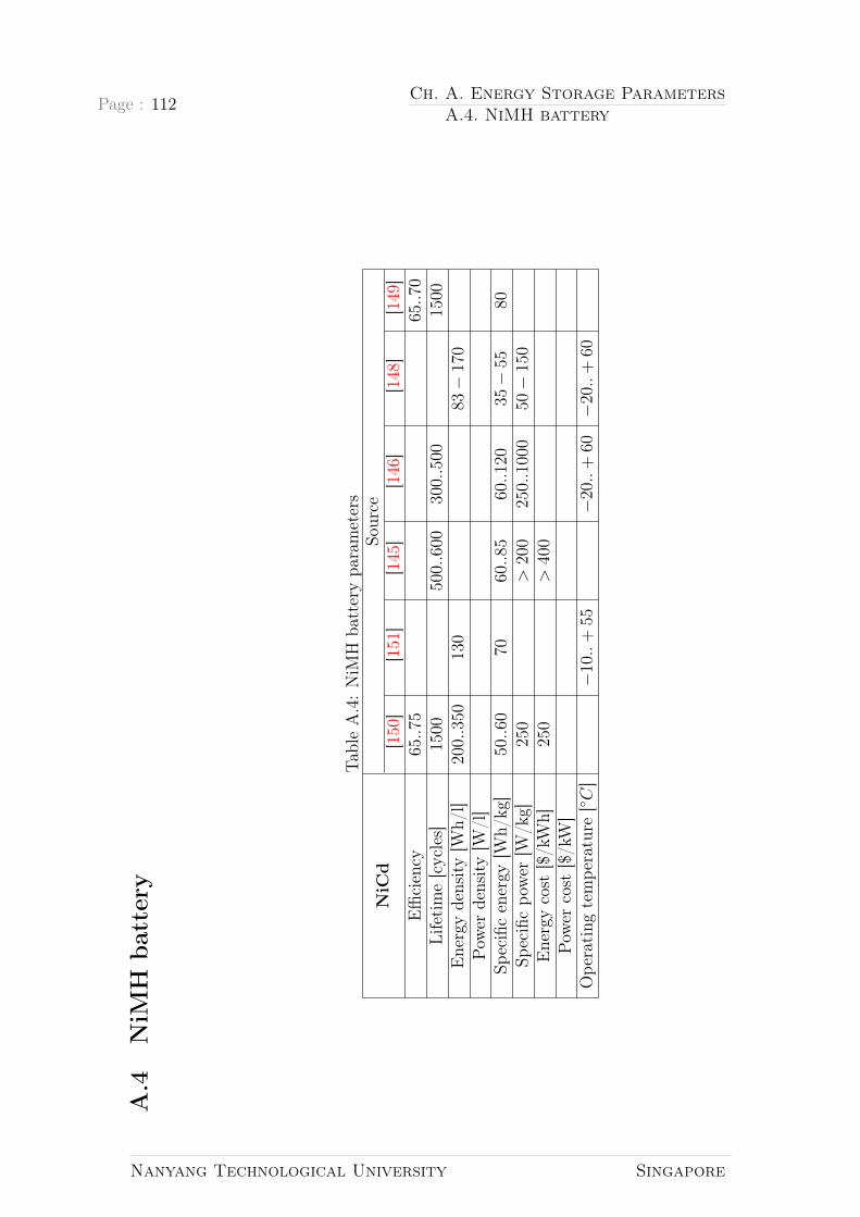
Page : 112 Ch. A. Energy Storage ParametersA.4. NiMH battery
A.4
NiM
Hba
ttery
TableA.4:NiM
Hba
tterypa
rameters
NiCd
Source
[150
][151
][145]
[146
][148
][149
]Efficiency
65..75
65..70
Lifetime[cycles]
1500
500..6
0030
0..5
0015
00Energydensity
[Wh/
l]20
0..3
5013
083−
170
Pow
erdensity
[W/l]
Specificenergy
[Wh/
kg]
50..60
7060..85
60..12
035−
5580
Specificpo
wer
[W/k
g]25
0>
200
250..1
000
50−
150
Energycost
[$/kW
h]25
0>
400
Pow
ercost
[$/kW
]Ope
rating
tempe
rature
[C]
−10..
+55
−20..
+60
−20..
+60
Nanyang Technological University Singapore

Ch. A. Energy Storage ParametersA.5. Li-ion battery
Page : 113
A.5
Li-ionba
ttery
TableA.5:Li-io
nba
tterypa
rameters
Li-ion
Source
[144
][150
][146
][147
][148]
[149
]Efficiency
>90
9585..95
>90
Lifetime[cycles]
1000−
1000
025
0050
0..1
000
1000..10
00>
1500
Energydensity
[Wh/
l]20
0..5
0040
0..6
0023
0−
500
Pow
erdensity
[W/l]
Specificenergy
[Wh/
kg]
75..20
015
0..2
0011
0..2
0075..
200
90−
200
80−
150
Specificpo
wer
[W/k
g]15
0..3
1554
018
0015
0..3
1575
0−
1250
50−
2000
Energycost
[$/kW
h]60
0−
2500
450
4790..50
6090
0−
1300
Pow
ercost
[$/kW
]12
00−
4000
1220..12
65Ope
rating
tempe
rature
[C]
−20..
+60
−30..
+60
−40..
+60
Nanyang Technological University Singapore

Page : 114 Ch. A. Energy Storage ParametersA.6. Supercapacitor
A.6
Supercapa
citor
TableA.6:Su
percap
acitor
parameters
SC
Source
[144
][152
][147
][148
][149
][153
]Efficiency
>90
8895
85..98
98Lifetime[cycles]
>10
0000
>10
0000
010
0000
0<
1000
000
>50
0000
>10
0000
Energydensity
[Wh/
l]10..30
<20
Pow
erdensity
[W/l]
>10
0000
Specificenergy
[Wh/
kg]
2..1
51..1
02..1
55
<5
Specificpo
wer
[W/k
g]50
0..5
000
1000..50
0050
0..5
000
1000
0>
1000
Energycost
[$/kW
h]30
0−
2000
9975
0..1
0640
020
000
Pow
ercost
[$/kW
]10
0−
300
811..8
40widerang
eOpe
rating
tempe
rature
[C]
−45..
+60
Nanyang Technological University Singapore

Appendix B
Small Signal Modeling of BoostConverter
The power circuit of the ith boost converter, with transistor Si as switch and outputfilter capacitor Ci is shown in Fig. B.1. The operating principle of the converter isbased on the periodic accumulation of energy and transferring it through inductorLi in the circuit with filter Ci and load Ri. The modes of operation of boost
Figure B.1: Power circuit of DC-DC boost converter
converter can be divided into two i.e. during switch-ON and during switch-OFFas shown in Fig. B.2(a) and Fig. B.2(b), respectively. The duration of Si-ON andSi-OFF are ton = dTsand toff = dTs respectively. Based upon Fig. B.2 (a) andFig. B.2 (b), the state equations for each interval of operation can be derived asfollows:
When switch Si is ON:
LidiLidt
= E (B.1)
115

Page : 116 Ch. B. Small Signal Modeling of Boost Converter
Figure B.2: Modes of operation in boost converter (a) when switch Si is ON(b)when switch Si is OFF
Cidvoidt
= −voiRi
(B.2)
When switch Si is OFF:
LidiLidt
= E − voi (B.3)
Cidvoidt
= iLi −voiRi
(B.4)
Where,
e : input voltage of boost converter;
Li: inductor current for ith boost converter;
Si: switch for ith boost converter;
Ci:bus capacitor for ith boost converter;
Ri: resistive load for ith boost converter;
Nanyang Technological University Singapore

Ch. B. Small Signal Modeling of Boost Converter Page : 117
Di: diode for ith boost converter;
voi: output voltage of ith boost converter;
vci: capacitor voltage of ith boost converter;
ioi: output current of ith boost converter;
ici: capacitor current of ith boost converter;
iLi: inductor current of ith boost converter;
Averaging state equations over a switching cycle, the following equations are ob-tained.
LidiLidt
= E − (1− d)voi (B.5)
Cidvoidt
= (1− d)iLi −voiRi
(B.6)
Introducing perturbation in state variables, the following expressions are achieved.
iLi = ILi + iLi
e = E + e
voi = Voi + voi
d = D + d (B.7)
Inclusion of above perturbations in (B.5) and (B.6) yields,
Li
d(iLi + iLi
)dt
= (E + e)−(
1−D − d)
(Voi + voi) (B.8)
Cid (Voi + voi)
dt=(
1−D − d)(
iLi + ˆiLi
)− (Voi + voi)
Ri
(B.9)
Equating AC and DC quantities and proceeding with AC equations, the followingcan be obtained.
LidiLidt
= e− (1−D) voi + Void (B.10)
Cidvoidt
= (1−D) iLi − ILid−voiRi
(B.11)
Taking Laplace transform and arranging in symmetrical sequence, the following
Nanyang Technological University Singapore

Page : 118 Ch. B. Small Signal Modeling of Boost Converter
expressions can be obtained.[sLi 1−D
1−D −(sCoi + 1
Ri
)] · [iLi(s)voi(s)
]=
[Voi
ILi
]· d(s) +
[1
0
]· e(s) (B.12)
[iLi(s)
voi(s)
]=
[sLi 1−D
1−D −(sCoi + 1
Ri
)]−1 · [VoiILi
]· d(s)
+
[sLi 1−D
1−D −(sCoi + 1
Ri
)]−1 · [1
0
]· e(s) (B.13)
Calculating inverse matrix, converter transfer function will be obtained as follows:
Control to output voltage transfer function
voi(s)
d(s)=
(1−D)Voi − (LiILi)(s)
(LC)s2 + LRs+ (1−D)2
(B.14)
Control to input current transfer function
iL(s)
d(s)=
(CVo)s+ 2(1−D)IL
(LC)s2 + LRs+ (1−D)2
(B.15)
Current to output transfer function
voi(s)
ˆiLi(s)=
(1−D)Voi − (LiILi)s
CiVois+ (1−D)ILi(B.16)
Nanyang Technological University Singapore

Author’s Publications
Journal Papers
1. Sujan Adhikari, Qianwen Xu, Yi Tang, PengWang, and Xiaoqiang Li. Decen-tralized control of two DC microgrids interconnected with tie-line. Journalof Modern Power Systems and Clean Energy, 5(4):599–608, 2017.
2. Sujan Adhikari, Zhe Zhang, Yi Tang, Peng Wang, and Yang Qi. Decentral-ized Voltage Balancing Control of Bipolar-Type DC Microgrids. IEEE trans.on Energy Conversion (submitted, under review), pages 1–7, 2017.
Conference Papers
1. Sujan Adhikari, Zhang Lei, Wang Peng, and Yi Tang. A Battery/SupercapacitorHybrid Energy Storage System for DC Microgrids. In 2016 IEEE 8th Inter-national Power Electronics and Motion Control Conference (IPEMC-ECCEAsia ), pages 1747–1753, 2016.
2. Sujan Adhikari, Yi Tang, and Peng Wang. Secondary Control for DC Micro-grids: A Review. In Asian Conference on Energy, Power and TransportationElectrification (ACEPT), number October, pages 1–6. IEEE, 2016.
3. Sujan Adhikari, Qianwen Xu, Yi Tang, and Peng Wang. Decentralized Con-trol of DCMicrogrid Clusters. In 2017 IEEE 3rd International Future EnergyElectronics Conference and ECCE Asia (IFEEC 2017-ECCE Asia), pages567–572, 2017.
119

Bibliography
[1] Allison Lantero. The War of the Currents: AC vs. DC Power, 2014.
[2] Carl L. Sulzberger. Triumph of AC, Part 2- the battle of the currents. IEEEPower and Energy Magazine, 99(4):70–73, 2003.
[3] Carl L. Sulzberger. Triumph of AC-From Pearl Street to Niagara. IEEEPower and Energy Magazine, 99(4):70–73, 2003.
[4] J A Momoh, S Meliopoulos, and R Saint. Centralized and Distributed Gen-erated Power Systems - A Comparison Approach, 2012.
[5] Robert H Lasseter and Paolo Paigi. Microgrid : A Conceptual Solution.In Power Electronics Specialists Conference, PESC ’04, pages 4285–4290.IEEE, 2004.
[6] Yun Wei Li and ChingNan Kao. An Accurate Power Control Strategy forPower-Electronics-Interfaced Distributed Generation Units Operating in aLow-Voltage Multibus Microgrid. IEEE Transactions on Power Electronics,24(12):2977–2988, 2009.
[7] Hassan Nikkhajoei and Robert H Lasseter. Distributed Generation In-terface to the CERTS Microgrid. IEEE Transactions on Power Delivery,24(3):1598–1608, 2009.
[8] P. Asmus. The Microgrid Revolution..., 2009.
[9] R H Lasseter. MicroGrids. In Power Engineering Society Winter Meeting,pages 305–308, 2002.
[10] Robert H Lasseter. Smart Distribution : Coupled Microgrids. IEEE,99(6):1074–1082, 2011.
121

Page : 122 Bibliography
[11] Seyedali Moayedi and Ali Davoudi. Distributed Tertiary Control of DCMicrogrid Clusters. IEEE Transactions on Power Electronics, 31(2):1717–1733, 2016.
[12] Luis Eduardo Zubieta. Are Microgrids the Future of Energy?: DC Micro-grids from Concept to Demonstration to Deployment. IEEE ElectrificationMagazine, 4(2):37–44, 2016.
[13] Sebastian Beer, Tomás Gómez, Senior Member, David Dallinger, IlanMomber, Chris Marnay, Michael Stadler, and Judy Lai. An Economic Anal-ysis of Used Electric Vehicle Batteries Integrated Into Commercial BuildingMicrogrids. IEEE Transactions on Smart Grid, 3(1):517–525, 2012.
[14] Zhongguan Wang, Wenchuan Wu, and Boming Zhang. A Distributed Con-trol Method with Minimum Generation Cost for DC Microgrids. IEEETransactions on Energy Conversion, 31(4):1462–1470, 2016.
[15] Xiong Liu, Peng Wang, and Poh Chiang Loh. A Hybrid AC/DC Micro-Gridand Its Coordination Control. IEEE Transactions on Smart Grid, 2(2):278–286, 2011.
[16] Poh Chiang Loh, Ding Li, Yi Kang Chai, and Frede Blaabjerg. AutonomousOperation of Hybrid Microgrid With AC and DC Subgrids. IEEE Transac-tions on Power Electronics, 28(5):2214–2223, 2013.
[17] Rajat Majumder, Caresten Bartzsch, Peter Kohnstam, Eric Fullerton, AllanFinn, and Wayne Galli. Magic Bus: High-Voltage DC on the New PowerTransmission Highway. IEEE Power and Energy Magazine 10.6, pages 39–49, 2012.
[18] Gregory F Reed. dc technologies-solutions to electric power system advance-ments. Power and Energy Magazine 10.6, pages 10–17, 2012.
[19] Ewan Pritchard and Daniel C. Gregory. The dc Revolution. IEEE Electri-fication Magazine 4.2, pages 4–9, 2016.
[20] Paul Savage, Robert R. Nordhaus, and Sean P. Jamieson. DC Microgrids:Benefits and Barriers. From Silos to Systems: Issues in Clean Energy andClimate Change, 26:51 – 66, 2010.
[21] Estefanía Planas, Jon Andreu, José Ignacio Gárate, Iñigo Martínez De Ale-gría, and Edorta Ibarra. AC and DC technology in microgrids : A review.Renewable and Sustainable Energy Reviews, ELSEVIER, 43:726–749, 2015.
Nanyang Technological University Singapore
Bibliography Page : 123
[22] K. Shenai and K. Shah. Smart DC Micro-grid for Efficient Utilization ofDistributed Renewable Energy. In IEEE 2011 EnergyTech, ENERGYTECH2011, pages 1–6, 2011.
[23] Chapter1. Benefits of Distributed Generation, 2007.
[24] Brian T. Patterson. DC, Come Home: : DC Microgrids and the Birth ofthe "Enernet". IEEE Power and Energy Magazine, 10(6)(October):60–69,2012.
[25] P D Lund and J V Paatero. Energy storage options for improving windpower quality. In 3rd Nordic Wind Power ConferenceNordic Wind PowerConference(NWPC 2006), pages 1–7, 2006.
[26] Jukka V. Paatero and Peter D. Lund. Impacts of Energy Storage in Distri-bution Grids With High Penetration of photovoltaic power. InternationalJournal of Distributed Energy Resources, 3(1):31–45, 2007.
[27] Joseph Carr, Juan Carlos Balda, and Alan Mantooth. A High FrequencyLink Multiport Converter Utility Interface for Renewable Energy Resourceswith Integrated Energy Storage. In 2010 IEEE Energy Conversion Congressand Exposition, ECCE 2010 - Proceedings, pages 3541–3548. IEEE, 2010.
[28] Z A Styczynski, P Lombardi, R Seethapathy, M Piekutowski, C. Ohler,B. Roberts, and S.C.Verma. Electric Energy Storage and its Tasks in theIntegration of Wide-Scale Renewable Resources. In 2009 CIGRE/IEEE PESJoint Symposium, Integration of Wide-Scale Renewable Resources Into thePower Delivery System, pages 1–11, Calgary, 2009. IEEE.
[29] S S Choi, K J Tseng, D M Vilathgamuwa, and T D Nguyen. Energy StorageSystems in Distributed Generation Schemes. In 2008 IEEE, Power and En-ergy Society General Meeting - Conversion and Delivery of Electrical Energyin the 21st Century, pages 1–8, Pittsburgh, PA, 2008. IEEE.
[30] John P. Barton and David G. Infield. Energy Storage and Its Use WithIntermittent Renewable Energy. IEEE Transactions on Energy Conversion,19(2):441–448, 2004.
[31] European Commission. Energy Storage: A key technology for decentralisedpower, power quality and clean transport. RTD info, Energy, environmentand sustainable development, page 24, 2000.
Nanyang Technological University Singapore

Page : 124 Bibliography
[32] Scott Backhaus, Gregory W Swift, Spyridon Chatzivasileiadis, WilliamTschudi, Steven Glover, Michael Starke, Jianhui Wang, Meng Yue, and Don-ald Hammerstrom. DCMicrogrids Scoping Study: Estimate of Technical andEconomic Benefits, 2015.
[33] Dong Chen and Lie Xu. Autonomous DC voltage control of a DC micro-grid with multiple slack terminals. IEEE Transactions on Power Systems,27(4):1897–1905, 2012.
[34] Avisha Tah and Debapriya Das. An Enhanced Droop Control Methodfor Accurate Load Sharing and Voltage Improvement of Isolated and In-terconnected DC Microgrids. IEEE Transactions on Sustainable Energy,7(3):1194–1204, 2016.
[35] Guishi Wang, Mihai Ciobotaru, and Vassilios G. Agelidis. Power smoothingof large solar PV plant using hybrid energy storage. IEEE Transactions onSustainable Energy, 5(3):834–842, 2014.
[36] Youichi Ito, Yang Zhongqing, and Hirofumi Akagi. DC Micro-grid BasedDistribution Power Generation System. In 4th International Conferenceon Power Electronics and Motion Control Conference (IPEMC), volume 3,pages 1740–1745, 2004.
[37] Tomislav Dragicevic, Xiaonan Lu, Juan Vasquez, and Josep Guerrero. DCMicrogrids-Part II: A Review of Power Architectures, Applications and Stan-dardization Issues. IEEE Transactions on Power Electronics, 31(5):3528 –3549, 2016.
[38] Dinesh Kumar, Firuz Zare, and Arindam Ghosh. DC Microgrid Technology:System Architectures, AC Grid Interfaces, Grounding Schemes, Power Qual-ity, Communication Networks, Applications and Standardizations Aspects.IEEE Access, PP(99):1–26, 2017.
[39] Catalin Gavriluta, J Ignacio Candela, Costantino Citro, Joan Rocabert, Al-varo Luna, and Pedro Rodríguez. Decentralized Primary Control of MTDCNetworks With Energy Storage and Distributed Generation. IEEE Trans-actions on Industry Applications, 50(6):4122–4131, 2014.
[40] Jiyong Li and Honghua Wang. Maximum Power Point Tracking of Photo-voltaic Generation Based on the Fuzzy Control Method. In InternationalConference on Sustainable Power Generation and Supply SUPERGEN’09,pages 1–6, 2009.
Nanyang Technological University Singapore
Bibliography Page : 125
[41] L. Barote, C. Marinescu, and M. Georgescu. VRB modeling for storagein stand-alone wind energy systems. In 2009 IEEE Bucharest PowerTech:Innovative Ideas Toward the Electrical Grid of the Future, pages 1–6. IEEE,2009.
[42] Fernando A. Inthamoussou, Jordi Pegueroles-Queralt, and Fernando D.Bianchi. Control of a supercapacitor energy storage system for microgrid ap-plications. IEEE Transactions on Energy Conversion, 28(3):690–697, 2013.
[43] Robert A Huggins. Energy Storage: Fundamentals, Materials and Applica-tions. Springer, second edi edition, 2015.
[44] Ziad Melhem. Electricity Transmission, Distribution and Storage Systems.Woodhead Publishing Limited, 2013.
[45] Dominic D. Banham-Hall, Gareth A. Taylor, Chris A. Smith, and Mal-colm R. Irving. Flow batteries for enhancing wind power integration. IEEETransactions on Power Systems, 27(3):1690–1697, 2012.
[46] Fangcheng Liu, Jinjun Liu, Haodong Zhang, and Danhong Xue. Stabil-ity Issues of Z+Z Type Cascade System in Hybrid Energy Storage System(HESS). IEEE Transactions on Power Electronics, 29(11):5846–5859, 2014.
[47] Jianfang Xiao, Peng Wang, and Leonardy Setyawan. Hierarchical Controlof Hybrid Energy Storage System in DC Microgrids. IEEE Transactions onIndustrial Electronics, 62(8):4915–4924, 2015.
[48] Lijun Gao, R.A. Dougal, and Shengyi Liu. Power enhancement of an activelycontrolled battery/ultracapacitor hybrid. IEEE Transactions on Power Elec-tronics, 20(1):236–243, 2005.
[49] Mamadou Baïlo Camara, Hamid Gualous, Frederic Gustin, and AlainBerthon. Design and new control of DC/DC converters to share energybetween supercapacitors and batteries in hybrid vehicles. IEEE Transac-tions on Vehicular Technology, 57(5):2721–2735, 2008.
[50] M Farhadi and O Mohammed. Performance Enhancement of Actively Con-trolled Hybrid DC Microgrid with Pulsed Load. IEEE Transactions onIndustry Applications, 51(99):1, 2015.
[51] Peng Wang, Jianfang Xiao, Leonardy Setyawan, Chi Jin, and Choo FookHoong. Hierarchical Control of Active Hybrid Energy Storage System (
Nanyang Technological University Singapore

Page : 126 Bibliography
HESS ) in DC Microgrids. In IEEE 9th Conference on Industrial Electronicsand Applications (ICIEA), pages 569–574, Hangzhou, 2014. IEEE.
[52] Mid-Eum Choi, Seong-Woo Kim, and Seung-Woo Seo. Energy ManagementOptimization in a Battery/Supercapacitor Hybrid Energy Storage System.IEEE Transactions on Smart Grid, 3(1):463–472, 2012.
[53] Jian Cao and Ali Emadi. A New Battery / UltraCapacitor Hybrid EnergyStorage System for Electric , Hybrid , and Plug-In Hybrid Electric Vehicles.IEEE Transactions on Power Electronics, 27(1):122–132, 2012.
[54] Haihua Zhou, T. Bhattacharya, Duong Tran, T.S.T. Siew, and A.M. Kham-badkone. Composite Energy Storage System Involving Battery and Ultra-capacitor With Dynamic Energy Management in Microgrid Applications.IEEE Transactions on Power Electronics, 26(3):923–930, 2011.
[55] Sujan Adhikari, Zhang Lei, Wang Peng, and Yi Tang. A Bat-tery/Supercapacitor Hybrid Energy Storage System for DC Microgrids. In2016 IEEE 8th International Power Electronics and Motion Control Con-ference (IPEMC-ECCE Asia ), pages 1747–1753, 2016.
[56] By Ashok Jhunjhunwala, Aditya Lolla, and Prabhjot Kaur. Solar-dc Micro-grid for Indian Homes: A transforming power scenario. IEEE ElectrificationMagazine 4.2, pages 10–19, 2016.
[57] Guy Ailee and William Tschudi. Edison Redux. IEEE Power and EnergyMagazine 10.6, pages 50–59, 2012.
[58] Dushan Boroyevich, Igor Cvetkovi, Dong Dong, Rolando Burgos, Fei Wang,and Fred Lee. Future Electronic Power Distribution Systems-A contempla-tive view-. In 12th International Conference on Optimization of Electricaland Electronic Equipment (OPTIM), IEEE, pages 1369–1380, 2010.
[59] Sandeep Anand, Baylon G Fernandes, and Josep M Guerrero. DistributedControl to Ensure Proportional Load Sharing and Improve Voltage Regula-tion in Low-Voltage DC Microgrids. IEEE Transactions on Power Electron-ics, 28(4):1900–1913, 2013.
[60] Tomislav Dragičević, Juan C Vasquez, and Davor Skrlec. Supervisory Con-trol of an Adaptive-Droop Regulated DC Microgrid With Battery Manage-ment Capability. IEEE Transactions on Power Electronics, 29(2):695–706,2014.
Nanyang Technological University Singapore

Bibliography Page : 127
[61] Tomislav Dragicevic, Josep M. Guerrero, and Juan C. Vasquez. A Dis-tributed Control Strategy for Coordination of an Autonomous LVDC Mi-crogrid Based on Power-Line Signaling. IEEE Transactions on IndustrialElectronics, 61(7):3313–3326, 2014.
[62] Xiaonan Lu, Josep M. Guerrero, Kai Sun, and Juan C. Vasquez. An im-proved droop control method for dc microgrids based on low bandwidthcommunication with dc bus voltage restoration and enhanced current shar-ing accuracy. IEEE Transactions on Power Electronics, 29(4):1800–1812,2014.
[63] Vahidreza Nasirian, Seyedali Moayedi, Ali Davoudi, and Frank L Lewis.Distributed Cooperative Control of DC Microgrids. IEEE Transactions onPower Electronics, 30(4):2288–2303, 2015.
[64] Hiroaki Kakigano, Yushi Miura, and Toshifumi Ise. Low-Voltage Bipolar-Type DC Microgrid for Super High Quality Distribution. IEEE Transactionson Power Electronics, 25(12):3066–3075, 2010.
[65] H Kakigano, Y Miura, T Ise, and R Uchida. DC Voltage Control of theDC Micro-grid for Super High Quality Distribution. In Power ConversionConference-Nagoya, 2007. PCC’07, pages 518–525, 2007.
[66] T. Dragicevic, J.C. Vasquez, J.M. Guerrero, and D Skrlec. Advanced LVDCElectrical Power Architectures and Microgrids. IEEE Electrification Maga-zine 2, (1):54–65, 2014.
[67] Qobad Shafiee, Tomislav Dragicevic, Juan C Vasquez, and Josep M Guer-rero. Hierarchical Control for Multiple DC-Microgrids Clusters. IEEE Trans-actions on Energy Conversion, 29(4):922–933, 2014.
[68] Jae-do Park, Jared Candelaria, Liuyan Ma, and Kyle Dunn. DC Ring-Bus Microgrid Fault Protection and Identification of Fault Location. IEEETransactions on Power Delivery, 28(4):2574–2584, 2013.
[69] Robert M Cuzner and Giri Venkataramanan. The Status of DC Micro-GridProtection. In Industry Applications Society Annual Meeting, IAS’08. IEEE,pages 1–8, 2008.
[70] Rodrigo Teixeira Pinto, Pavol Bauer, Sílvio F Rodrigues, Edwin JanWiggelinkhuizen, Jan Pierik, and Braham Ferreira. A Novel DistributedDirect-Voltage Control Strategy for Grid Integration of Offshore Wind En-
Nanyang Technological University Singapore

Page : 128 Bibliography
ergy Systems Through MTDC Network. IEEE Transactions on IndustrialElectronics, 60(6):2429–2441, 2013.
[71] Weixing Lu and Boon Teck Ooi. Multiterminal LVDC System for Opti-mal Acquisition of Power in Wind-Farm Using Induction Generators. IEEETransactions on Power Electronics, 17(4):558–563, 2002.
[72] Weixing Lu and Boon Teck Ooi. Multi-Terminal HVDC As Enabling Tech-nology of Premium Quality Power Park. In Power Engineering Society Win-ter Meeting, IEEE, volume 2, pages 719–724, 2002.
[73] Enrico Tironi, Matteo Corti, and Giovanni Ubezio. Zonal electrical distribu-tion systems in large ships: Topology and contro. In International AnnualConference (AEIT), IEEE, pages 1–6, 2015.
[74] Bryan G Dobbs and Patrick L Chapman. A Multiple-Input DC-DC Con-verter Topology. IEEE POWER ELECTRONICS LETTERS, 1(1):6–9,2003.
[75] Alexis Kwasinski. Identification of Feasible Topologies for Multiple-InputDC- DC Converters. IEEE Transactions on Power Electronics, 24(3):856–861, 2009.
[76] John G Ciezki and Robert W Ashton. Selection and Stability Issues Associ-ated with a Navy Shipboard DC Zonal Electric Distribution System. IEEETransactions on Power Delivery, 15(2):665–669, 2000.
[77] Tomislav Dragicevic, Xiaonan Lu, Juan Vasquez, and Josep Guerrero. DCMicrogrids - Part I: A Review of Control Strategies and Stabilization Tech-niques. IEEE Transactions on Power Electronics, 31(7):4876–4891, 2016.
[78] Jin Chi, Peng Wang, Jianfang Xiao, Yi Tang, and Fook Hoong Choo. Im-plementation of Hierarchical Control in DC microgrids. IEEE Transactionson Industrial Electronics, 61(8):4032–4042, 2014.
[79] Yunjie Gu, Xin Xiang, Wuhua Li, and Xiangning He. Mode-Adaptive De-centralized Control for Renewable DC Microgrid With Enhanced Reliabilityand Flexibility. IEEE Transactions on Power Electronics, 29(9):5072–5080,2014.
[80] Amir Khorsandi, Mojtaba Ashourloo, and Hossein Mokhtari. A Decentral-ized Control Method for a Low-Voltage DC Microgrid. IEEE Transactionson Energy Conversion, 29(4):793–801, 2014.
Nanyang Technological University Singapore

Bibliography Page : 129
[81] Sujan Adhikari, Yi Tang, and Peng Wang. Secondary Control for DC Micro-grids: A Review. In Asian Conference on Energy, Power and TransportationElectrification (ACEPT), number October, pages 1–6. IEEE, 2016.
[82] Marko Gulin. Control of a DC Microgrid, 2009.
[83] Ramon Zamora and Anurag K. Srivastava. Controls for microgrids withstorage: Review, challenges, and research needs. Renewable and SustainableEnergy Reviews, ELSEVIER, 14:2009–2018, 2010.
[84] Fernando Valenciaga and Paul F Puleston. Supervisor Control for a Stand-Alone Hybrid Generation System Using Wind and Photovoltaic Energy.IEEE Transactions on Energy Conversion, 20(2):398–405, 2005.
[85] Yixin Zhu, Fang Zhuo, and Liansong Xiong. Communication Platform forEnergy Management System in a Master-slave Control Structure Microgrid.In Power Electronics and Motion Control Conference (IPEMC), pages 141–145, 2012.
[86] P. Karlsson and J. Svensson. DC bus voltage control for a distributed powersystem. IEEE Transactions on Power Electronics, 18(6):1405–1412, 2003.
[87] Daniel Salomonsson, Lennart Söder, and Ambra Sannino. An AdaptiveControl System for a DC Microgrid for Data Centers. IEEE Transactionson Industry Applications, 44(6):1910–1917, 2008.
[88] Vehbi C Güngör, Dilan Sahin, Taskin Kocak, Salih Ergüt, Concettina Buc-cella, Carlo Cecati, and Gerhard P Hancke. Smart Grid Technologies : Com-munication Technologies and Standards. IEEE Transactions on IndustrialInformatics, 7(4):529–539, 2011.
[89] Robert Caiming Qiu, Zhen Hu, Zhe Chen, Nan Guo, Raghuram Ran-ganathan, Shujie Hou, and Gang Zheng. Cognitive Radio Network for theSmart Grid : Experimental System Architecture , Control Algorithms, Se-curity, and Microgrid Testbed. IEEE Transactions on Smart Grid, 2(4):724–740, 2011.
[90] L. Meng, Q. Shafiee, G. F. Trecate, H. Karimi, Fulwani D., X. Lu, and J. M.Guerrero. Review on Control of DC Microgrids. IEEE Journal of Emergingand Selected Topics in Power Electronics., PP(99):1–21, 2017.
Nanyang Technological University Singapore

Page : 130 Bibliography
[91] Reza Olfati-Saber and Richard M. Murray. Consensus Problems in Networksof Agents With Switching Topology and Time-Delays. IEEE Transactionson Automatic Control, 49(9):1520–1533, 2004.
[92] Vahidreza Nasirian, Ali Davoudi, Frank L Lewis, and Josep M Guerrero.Distributed Adaptive Droop Control for DC Distribution Systems. IEEETransactions on Energy Conversion, 29(4):944–956, 2014.
[93] Hamid Behjati, Ali Davoudi, and Frank Lewis. Modular DC âĂŞ DC Con-verters on Graphs : Cooperative Control. IEEE Transactions on PowerElectronics, 29(12):6725–6741, 2014.
[94] Panbao Wang, Xiaonan Lu, Xu Yang, Wei Wang, and Dianguo Xu. AnImproved Distributed Secondary Control Method for DC Microgrids withEnhanced Dynamic Current Sharing Performance. IEEE Transactions onPower Electronics, 31(9):6658–6673, 2016.
[95] Josep M. Guerrero, Juan C. Vasquez, José Matas, Luis García de Vicuna,and Miguel Castilla. Hierarchical Control of Droop-Controlled AC and DCMicrogrids - A General Approach Toward Standardization. IEEE Transac-tions on Industrial Electronics, 58(1):158–172, 2011.
[96] J Bryan, R Duke, and S Round. Decentralized Generator Scheduling ina Nanogrid Using DC bus Signaling. In IEEE Power Engineering SocietyGeneral Meeting, pages 977–982, 2004.
[97] J. Schonberger, R. Duke, and S.D. D Round. DC-Bus Signaling: A Dis-tributed Control Strategy for a Hybrid Renewable Nanogrid. IEEE Trans-actions on Industrial Electronics, 53(5):1453–1460, 2006.
[98] Kai Kai Sun, Li Li Zhang, Yan Yan Xing, and J. M. Guerrero. A DistributedControl Strategy Based on DC Bus Signaling for Modular Photovoltaic Gen-eration Systems With Battery Energy Storage. IEEE Transactions on PowerElectronics, 26(10):3032–3045, 2011.
[99] Jianfang Xiao, Leonardy Setyawan, Peng Wang, and Chi Jin. Power-Capacity-Based Bus-Voltage Region Partition and Online Droop CoefficientTuning for Real-Time Operation of DC Microgrids. IEEE Transactions onEnergy Conversion, 30(4):1338–1347, 2015.
[100] Xiaonan Lu, Kai Sun, J M Guerrero, J C Vasquez, and Lipei Huang. State-of-Charge Balance Using Adaptive Droop Control for Distributed Energy
Nanyang Technological University Singapore

Bibliography Page : 131
Storage Systems in DC Microgrid Applications. IEEE Transactions on In-dustrial Electronics, 61(6):2804–2815, 2014.
[101] Xiaonan Lu, Kai Sun, Josep M Guerrero, Juan C Vasquez, and Lipei Huang.Double-Quadrant State-of-Charge-Based Droop Control Method for Dis-tributed Energy Storage Systems in Autonomous DC Microgrids. IEEETransactions on Smart Grid, 6(1):147–157, 2015.
[102] Thiago Ribeiro Oliveira, Waner Wodson Aparecido Goncalves Silva, and Pe-dro Francisco Donoso-Garcia. Distributed Secondary Level Control for En-ergy Storage Management in DC Microgrids. IEEE Transactions on SmartGrid, PP(99):1–11, 2016.
[103] Nishad Mendis, Kashem Muttaqi, and Sarath Perera. Management of Low- and High- Frequency Power Components in Demand-Generation Fluctu-ations of a DFIG-based Wind Dominated RAPS System Using Hybrid En-ergy Storage. IEEE Transactions on Industry Applications, 50(3):2258–2268,2014.
[104] Yuru Zhang and Yun Wei Li. Energy Management Strategy for Superca-pacitor in Droop-controlled DC Microgrid Using Virtual Impedance. IEEETransactions on Power Electronics, 32(4):2704 – 2716, 2017.
[105] REbus DC Microgrid.
[106] W Stefanutti, S Saggini, P Mattavelli, and M Ghioni. Power Line Communi-cation in Digitally Controlled DC-DC Converters Using Switching FrequencyModulation. IEEE Transactions on Industrial Electronics, 55(4):1509–1518,2008.
[107] B. F. Wollenberg and A. J. Wood. Power Generation, Operation, and Con-trol. John Wiley & Sons, Inc., 1984.
[108] J M Guerrero, L Hang, and J Uceda. Control of Distributed Uninterrupt-ible Power Supply Systems. IEEE Transactions on Industrial Electronics,55(8):2845–2859, 2008.
[109] Hye-Jin Kim, Chang Yoon Chun, Kyung-Jun Lee, Paul Jang, and Bo-HyungCho. Control Strategy of Multiple Energy Storages System for DC Micro-grid. In 9th International Conference on Power Electronics and ECCE Asia(ICPE-ECCE Asia), pages 1750–1755, Seoul, 2015. IEEE.
Nanyang Technological University Singapore

Page : 132 Bibliography
[110] Fatih Cingoz, Ali Elrayyah, and Yilmaz Sozer. Optimized Droop ControlParameters for Effective Load Sharing and Voltage Regulation in DC Mi-crogrids. Electric Power Components and Systems, 43(8-10):879–889, 2015.
[111] Yunjie Gu, Wuhua Li, and Xiangning He. Frequency-Coordinating VirtualImpedance for Autonomous Power Management of DC Microgrid. IEEETransactions on Power Electronics, 30(4):2328–2337, 2015.
[112] Robert S. Balog and Philip T. Krein. Bus selection in multibus DC micro-grids. IEEE Transactions on Power Electronics, 26(3):860–867, 2011.
[113] Alexis Kwasinski and Chimaobi N. Onwuchekwa. Dynamic behavior and sta-bilization of DC microgrids with instantaneous constant-power loads. IEEETransactions on Power Electronics, 26(3):822–834, 2011.
[114] Josep M. Guerrero, Mukul Chandorkar, Tzung-Lin Lee, and Poh ChiangLoh. Advanced Control Architectures for Intelligent Microgrids-Part I: De-centralized and Hierarchical Control. IEEE Transactions on Industrial Elec-tronics, 60(4):1254–1262, 2013.
[115] Nilanjan Ray Chaudhuri and Balarko Chaudhuri. Adaptive Droop Controlfor Effective Power Sharing in Multi-Terminal DC (MTDC) Grids. IEEETransactions on Power Systems, 28(1):21–29, 2013.
[116] Nelson L. Diaz, T. Dragičević, J. C. Vasquez, and Josep M. Guerrero. Intel-ligent Distributed Generation and Storage Units for DC Microgrids- A NewConcept on Cooperative Control Without Communications Beyond DroopControl. IEEE Transactions on Smart Grid, 5(5):2476–2485, 2014.
[117] Mahesh Kumar, Suresh Chandra Srivastava, Sri Niwas Singh, andMylavarapu Ramamoorty. Development of a control strategy for interconnec-tion of islanded direct current microgrids. IET Renewable Power generation,9(3,4):284–296, 2015.
[118] Qobad Shafiee, Tomislav Dragicevic, Juan Carlos Vasquez, and Josep M.Guerrero. Hierarchical Control for Multiple DC-Microgrids Clusters. InSystems, Signals & Devices (SSD). IEEE, 2014.
[119] Nathan Cohn. Some Aspects of Tie-Line Bias Control on InterconnectedPower Systems. Transactions of the American Institute of Electrical Engi-neers. Part III: Power Apparatus and Systems, pages 1415–1436, 1957.
Nanyang Technological University Singapore
Bibliography Page : 133
[120] Prakash K Ray, Soumya R Mohanty, and Nand Kishor. Small-signal analysisof autonomous hybrid distributed generation systems in presence of ultraca-pacitor and tie-line operation. Journal of Electrical Engineering, 61(4):205–214, 2010.
[121] H. Shayeghi, H. A. Shayanfar, and A. Jalili. Load frequency control strate-gies: A state-of-the-art survey for the researcher. Energy Conversion andManagement, ELSEVIER, 50(2):344–353, 2009.
[122] Shashi Kant Pandey, Soumya R Mohanty, and Nand Kishor. A literaturesurvey on load âĂŞ frequency control for conventional and distribution gen-eration power systems. Renewable and Sustainable Energy Reviews, ELSE-VIER, 25(September):318–334, 2013.
[123] Qobad Shafiee, Tomislav Dragicevic, Juan C Vasquez, and Josep M Guer-rero. Modeling , Stability Analysis and Active Stabilization of MultipleDC-Microgrid Clusters. In ENERGYCON. IEEE, 2014.
[124] Chendan Li, Sanjay K. Chaudhary, Mehdi Savaghebi, Juan C. Vasquez,and Josep M. Guerrero. Power Flow Analysis for Low-Voltage AC andDC Microgrids Considering Droop Control and Virtual Impedance. IEEETransactions on Smart Grid, PP(99):1–11, 2016.
[125] Sujan Adhikari, Qianwen Xu, Yi Tang, Peng Wang, and Xiaoqiang Li. De-centralized control of two DC microgrids interconnected with tie-line. Jour-nal of Modern Power Systems and Clean Energy, 5(4):599–608, 2017.
[126] NERC. Transmission Relay Loadability.
[127] Manuel Reta-Hernandez. Transmission Line Parameters.
[128] Lidong Zhang, Lennart Harnefors, and Hans Peter Nee. Modeling and Con-trol of VSC-HVDC Links Connected to Island Systems. IEEE Transactionson Power Systems, 26(2):783–793, 2011.
[129] Grain Philip Adam, Khaled H Ahmed, Stephen J Finney, Keith Bell, andBarry W Williams. New Breed of Network Fault-Tolerant Voltage-Source-Converter HVDC Transmission System. IEEE Transactions on Power Sys-tems, 28(1):335–346, 2013.
[130] Yunjie Gu, Wuhua Li, and Xiangning He. Analysis and Control of BipolarLVDC Grid with DC symmetrical Component Method. IEEE Transactionson Power Systems, 31(1):685–694, 2016.
Nanyang Technological University Singapore
Page : 134 Bibliography
[131] D. Salomonsson and A. Sannino. Low-Voltage DC Distribution System forCommercial Power Systems With Sensitive Eectornic Loads. IEEE Trans-actions on Power Delivery, 22(3):1620–1627, 2007.
[132] Fred C Lee, Peter Barbosa, Peng Xu, Jindong Zhang, B O Yang, and Fran-cisco Canales. Topologies and Design Considerations for Distributed PowerSystem Applications. Proceedings of IEEE, 89(6):939–950, 2001.
[133] H Zhang, F Mollet, C Saudemont, and B Robyns. Experimental Validation ofEnergy Storage System Management Strategies for a Local DC DistributionSystem of More Electric Aircraft. Industrial Electronics, IEEE Transactionson, 57(12):3905–3916, 2010.
[134] G. Byeon, T. Yoon, S. Oh, and G. Jang. Energy Management Strategy ofthe DC Distribution System in Buildings Using the EV Service Model. IEEETransactions on Power Electronics, 28(4):1544–1554, 2013.
[135] Hiroaki Kakigano, Yushi Miura, Toshifumi Ise, and Ryohei Uchida. DCMicro-grid for Super High Quality Distribution - System Configuration andControl of Distributed Generations and Energy storage Devices -. In 37thIEEE Power Electronics Specialists Conference, PESC ’06, pages 1–7. IEEE,2006.
[136] Jackson Lago and Marcelo Lobo Heldwein. Operation and Control-OrientedModeling of a Power Converter for Current Balancing and Stability Improve-ment of DC Active Distribution Networks. IEEE Transactions on PowerElectronics, 26(3):877–885, 2011.
[137] Saman Dadjo Tavakoli, Jasem Khajesalehi, Mohsen Hamzeh, and Key-han Sheshyekani. Decentralised voltage balancing in bipolar dc microgridsequipped with trans-z-source interlinking converter. IET Renewable PowerGeneration, 10(5):703–712, 2016.
[138] Hiroaki Kakigano, Yushi Miura, and Toshifumi Ise. Distribution VoltageControl for DC Microgrids Using Fuzzy Control and Gain-Scheduling Tech-nique. Power Electronics, IEEE Transaction, 28(5):2246–2258, 2013.
[139] Maria Bella Ferrera, Salvador P. Litran, Eladio Duran Aranda, andJose Manuel Andujar Marquez. A Converter for Bipolar DC Link Basedon SEPIC-Cuk Combination. IEEE Transactions on Power Electronics,30(12):6483–6487, 2015.
Nanyang Technological University Singapore

Bibliography Page : 135
[140] S.M. Schoenung and W.V. Hassenzahl. Long- vs . Short-Term Energy Stor-age Technologies Analysis- A Life-Cycle Cost Study A Study for the DOEEnergy Storage Systems Program. Technical Report April, Sandia NationalLaboratories, 2003.
[141] S. Eckroad and I. Gyuk. EPRI-DOE Handbook of Energy Storage for Trans-mission & Distribution Applications. Technical report, EPRI-DOE, 2003.
[142] Adolfo Gonzalez, Brian O Gallachoir, Eamon McKeogh, and Kevin Lynch.Study of Electricity Storage Technologies and Their Potential to AddressWind Energy Intermittency in Ireland. Technical report, Sustainable EnergyIreland, 2004.
[143] Susan M Schoenung and Jim Eyer. Benefit/Cost Framework for EvaluatingModular Energy Storage -A Study for the DOE Energy Storage SystemsProgram. Technical Report February, Sandia National Laboratories, 2008.
[144] Haisheng Chen, Thang Ngoc Cong, Wei Yang, Chunqing Tan, Yongliang Li,and Yulong Ding. Progress in electrical energy storage system: A criticalreview. ScienceDirect, Progress in Natural Science, ELSEVIER, 19(3):291–312, 2009.
[145] Elton J. Cairns. Batteries, Overview. Encyclopedia of Energy, 1:117–126,2004.
[146] Xiaopeng Chen, Weixiang Shen, Thanh Tu Vo, Zhenwei Cao, and AjayKapoor. An overview of lithium-ion batteries for electric vehicles. In 201210th International Power & Energy Conference (IPEC), pages 230–235, HoChi Minh City, 2012. IEEE.
[147] Daniel Ioan Stroe, Ana Irina Stan, Robert Diosi, Remus Teodorescu, andSøren Juhl Andreasen. Short term energy storage for grid support in windpower applications. In International Conference on Optimisation of Elec-trical and Electronic Equipment, OPTIM, pages 1012–1021, Brasov, 2012.IEEE.
[148] Stephen Mccluer and Jean-francois Christin. Comparing Data Center Bat-teries , Flywheels , and Ultracapacitors. Technical report, Schneider electric,2011.
[149] Ioannis Hadjipaschalis, Andreas Poullikkas, and Venizelos Efthimiou.Overview of current and future energy storage technologies for electric power
Nanyang Technological University Singapore

Page : 136 Bibliography
applications. Renewable and Sustainable Energy Reviews, ELSEVIER, 13(6-7):1513–1522, 2009.
[150] P. Vishnu, R. Ajaykrishna, and S. Thirumalini. Cost Effective Energy So-lution with Dual Battery for Plug-in Hybrid Electric Vehicle (PHEV) in aPublic Transportation System. In 7th IEEE Conference on Industrial Elec-tronics and Applications, ICIEA, pages 1555–1560, Singapore, 2012. IEEE.
[151] Alexander Kusko and John Dedad. Short-Term, Long-Term, Energy Stor-age Methods for Standby Electric Power Systems. In Industry ApplicationsConference, 2005. Fourtieth IAS Annual Meeting. Conference Record of the2005, vol. 4, pages 2672–2678. IEEE, 2005.
[152] H. Ibrahim, A. Ilinca, and J. Perron. Energy storage systems-Characteristicsand comparisons. Renewable and Sustainable Energy Reviews, ELSEVIER,12(5):1221–1250, 2008.
[153] S. Mallika and R. Saravana Kumar. Review on ultracapacitor- battery inter-face for energy management system. International Journal of Engineeringand Technology, 3(1):37–43, 2011.
[154] Sujan Adhikari, Zhe Zhang, Yi Tang, Peng Wang, and Yang Qi. Decen-tralized Voltage Balancing Control of Bipolar-Type DC Microgrids. IEEEtrans. on Energy Conversion (submitted, under review), pages 1–7, 2017.
[155] Sujan Adhikari, Qianwen Xu, Yi Tang, and Peng Wang. Decentralized Con-trol of DCMicrogrid Clusters. In 2017 IEEE 3rd International Future EnergyElectronics Conference and ECCE Asia (IFEEC 2017-ECCE Asia), pages567–572, 2017.
Nanyang Technological University Singapore