control and management system -...
TRANSCRIPT
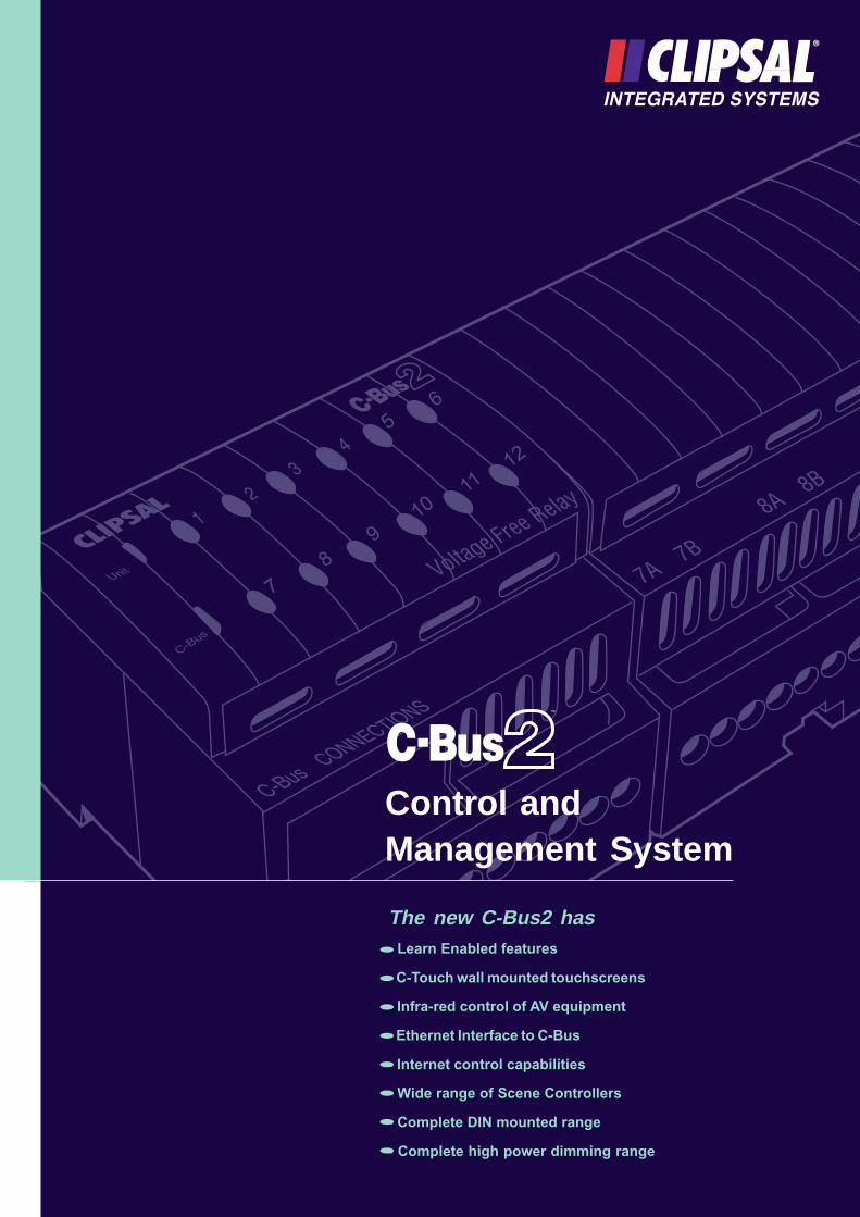
The new C-Bus2 has- Learn Enabled features
- C-Touch wall mounted touchscreens
- Infra-red control of AV equipment
- Ethernet Interface to C-Bus
- Internet control capabilities
- Wide range of Scene Controllers
- Complete DIN mounted range
- Complete high power dimming range
Control andManagement System
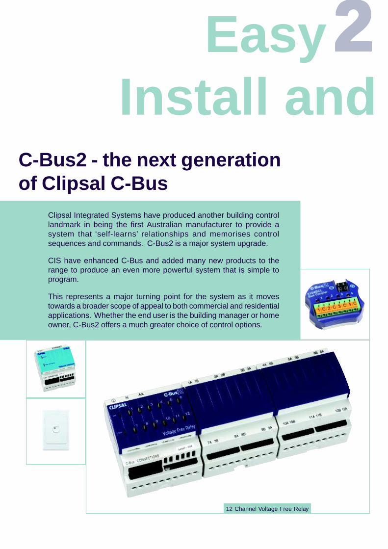
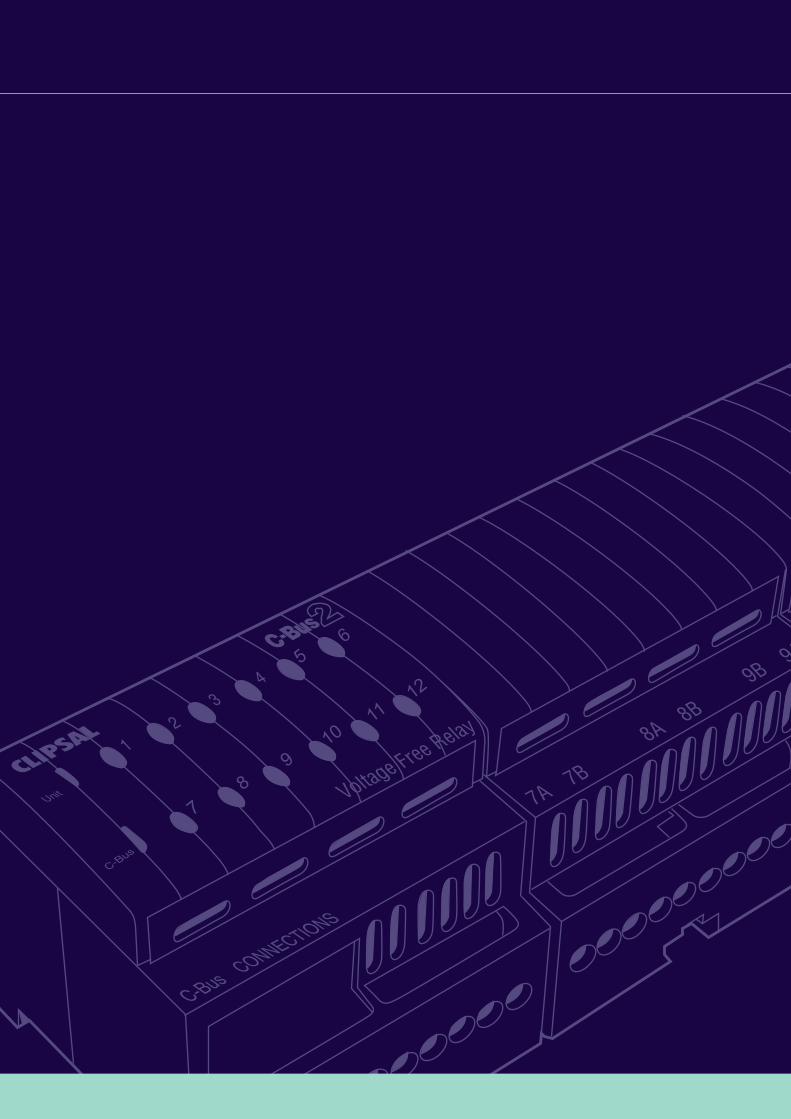
12 Channel Voltage Free Relay
22222
Clipsal Integrated Systems have produced another building controllandmark in being the first Australian manufacturer to provide asystem that ‘self-learns’ relationships and memorises controlsequences and commands. C-Bus2 is a major system upgrade.
CIS have enhanced C-Bus and added many new products to therange to produce an even more powerful system that is simple toprogram.
This represents a major turning point for the system as it movestowards a broader scope of appeal to both commercial and residentialapplications. Whether the end user is the building manager or homeowner, C-Bus2 offers a much greater choice of control options.
Easy Install and
C-Bus2 - the next generationof Clipsal C-Bus
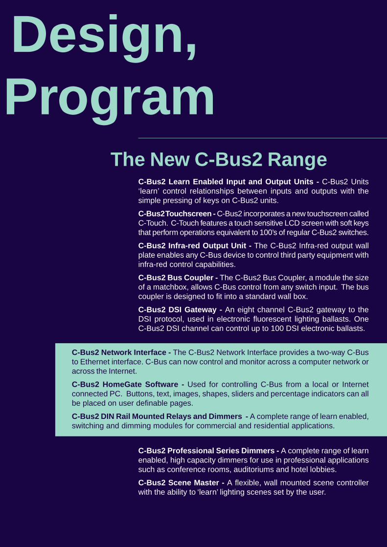
C-Bus2 Learn Enabled Input and Output Units - C-Bus2 Units‘learn’ control relationships between inputs and outputs with thesimple pressing of keys on C-Bus2 units.
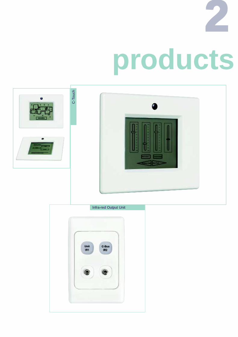
C-Bus2 Touchscreen - C-Bus2 incorporates a new touchscreen calledC-Touch. C-Touch features a touch sensitive LCD screen with soft keysthat perform operations equivalent to 100’s of regular C-Bus2 switches.
C-Bus2 Infra-red Output Unit - The C-Bus2 Infra-red output wallplate enables any C-Bus device to control third party equipment withinfra-red control capabilities.
C-Bus2 Bus Coupler - The C-Bus2 Bus Coupler, a module the sizeof a matchbox, allows C-Bus control from any switch input. The buscoupler is designed to fit into a standard wall box.
C-Bus2 DSI Gateway - An eight channel C-Bus2 gateway to theDSI protocol, used in electronic fluorescent lighting ballasts. OneC-Bus2 DSI channel can control up to 100 DSI electronic ballasts.
C-Bus2 Network Interface - The C-Bus2 Network Interface provides a two-way C-Busto Ethernet interface. C-Bus can now control and monitor across a computer network oracross the Internet.
C-Bus2 HomeGate Software - Used for controlling C-Bus from a local or Internetconnected PC. Buttons, text, images, shapes, sliders and percentage indicators can allbe placed on user definable pages.
C-Bus2 DIN Rail Mounted Relays and Dimmers - A complete range of learn enabled,switching and dimming modules for commercial and residential applications.
C-Bus2 Professional Series Dimmers - A complete range of learnenabled, high capacity dimmers for use in professional applicationssuch as conference rooms, auditoriums and hotel lobbies.
C-Bus2 Scene Master - A flexible, wall mounted scene controllerwith the ability to ‘learn’ lighting scenes set by the user.
Design,Program
The New C-Bus2 Range
22222 products
C-T
ouch
Infra-red Output Unit
many newto choose from!
C-Touch provides a touch sensitive LCD screen with “soft keys” whichbehave in a similar way to the keys on a regular C-Bus2 Key InputUnit. C-Touch is customised by means of the WindowsTM installationsoftware.· C-Touch connects to and is powered from the C-Bus network, no
extra external power supply is required· C-Touch is able to receive and act on infra-red commands· C-Touch incorporates a Real Time Clock and can be used to
schedule real time events· C-Touch can be configured to control 100’s of “soft keys”· Buttons with text and/or images, text, bitmap images, shapes,
sliders, clocks and percent indicators can all be placed on aC-Touch page
· All pages on C-Touch can be password protected· Pressing a screen component on a C-Touch screen can be
configured to start:- a C-Bus command (on/off/ramp/ramp rate)
- a preset-scene activation
- an audible output
- a link to another page
C-Bus2 Learn Enabled Units ‘learn’ control relationships with thesimple pressing of keys on C-Bus units. They also enable users toset input units as on/off switches, dimmers, or time delay switches.
No longer is a PC required to set up and commission a system.All the installer or user needs to do is to simply program theC-Bus2 units directly by pressing keys on C-Bus2 units.
The option still remains to commission a C-Bus installation with a PC. The coretechnology of the new system is the same as its predecessor and is entirelycompatible with all previous C-Bus products.
C-Bus2 Learn Enabled Units
C-Touch Touch Screen
The Infra-red Output Unit is a C-Bus2 device that allows control of infra-redproducts such as A/V components installed in boardrooms, homes, etc. Infra-red command strings are stored in non-volatile memory that resides within theC-Bus2 Infra-red Output Unit.· The C-Bus2 Infra-red Output Unit connects to a C-Bus UTP unshielded
Cat 5 network - no other external power source is required· The C-Bus2 Infra-red Output Unit module uses any input device connected
to C-Bus to initiate infra-red commands· Each infra-red channel is software addressable with macro infra-red
commands· The C-Bus2 Infra-red Output Unit device can store approximately 200
unique infra-red codes· The C-Bus2 Infra-red Output Unit unit has the capacity for connection of
two 3.5mm mono mini plug emitter cables with single or dual infra-redemitter(s)
· Any C-Bus2 Group Address can be ‘mapped’ to any combination of thetwo infra-red output zones on the C-Bus Infra-red Output Unit
· The Infra-red Output Unit mounts to a standard single gang wall plate
With Scene Master a user can access up to five lighting scenes (switching/dimmingpatterns) plus a Master-Off scene at the press of a button. Other features include:
· Scene Master has the ability to ‘learn’ lighting scenes set by the user· The lighting system can be set up so that any scene can be recalled from
any switch connected to C-Bus· Scene Master comes with a credit card sized, hand held infra-red remote
control unit· Scene Master can be used to control any combination of C-Bus lighting groups· Scene Master can control up to 33 groups of lighting
C-Bus Infra-red Output Unit
C-Bus Scene Master for total control
Dimming fluorescent lighting analogue control via a 0-10Vdc has been popularfor over 10 years now, but it has limitations. The ballast circuit still needs to beswitched on and off as the 0-10V analogue signal can not be used to switchthe luminaire. The 0-10V signal is also affected by volt drop, so only limitedruns were possible without signal amplification.
C-Bus DSI Gateway
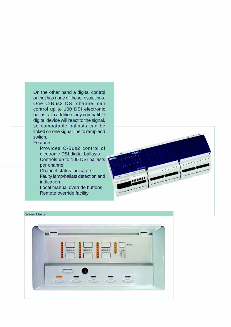
On the other hand a digital controloutput has none of these restrictions.One C-Bus2 DSI channel cancontrol up to 100 DSI electronicballasts. In addition, any compatibledigital device will react to the signal,so compatable ballasts can belinked on one signal line to ramp andswitch.Features:· Provides C-Bus2 control of
electronic DSI digital ballasts· Controls up to 100 DSI ballasts
per channel· Channel status indicators· Faulty lamp/ballast detection and
indication· Local manual override buttons· Remote override facility
Scene Master
Hom
eGat
e S
oftw
are
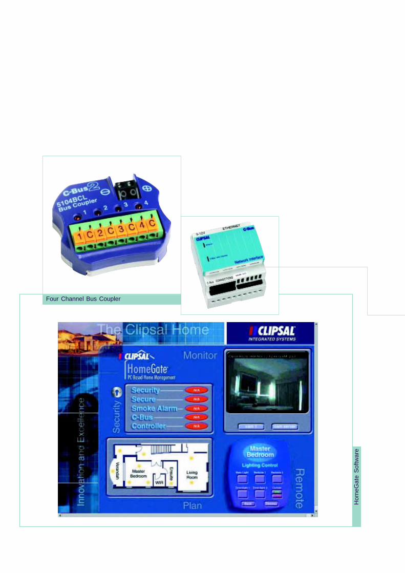
Four Channel Bus Coupler
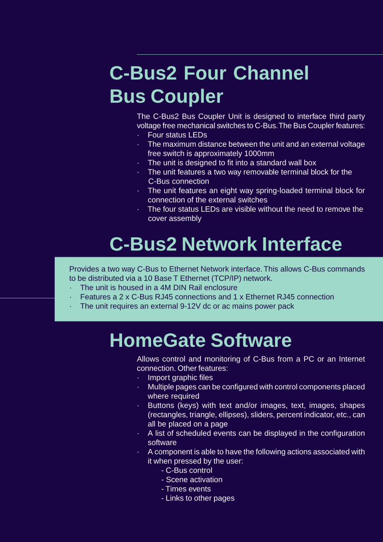
Provides a two way C-Bus to Ethernet Network interface. This allows C-Bus commandsto be distributed via a 10 Base T Ethernet (TCP/IP) network.· The unit is housed in a 4M DIN Rail enclosure· Features a 2 x C-Bus RJ45 connections and 1 x Ethernet RJ45 connection· The unit requires an external 9-12V dc or ac mains power pack
Allows control and monitoring of C-Bus from a PC or an Internetconnection. Other features:· Import graphic files· Multiple pages can be configured with control components placed
where required· Buttons (keys) with text and/or images, text, images, shapes
(rectangles, triangle, ellipses), sliders, percent indicator, etc., canall be placed on a page
· A list of scheduled events can be displayed in the configurationsoftware
· A component is able to have the following actions associated withit when pressed by the user:
- C-Bus control - Scene activation - Times events - Links to other pages
The C-Bus2 Bus Coupler Unit is designed to interface third partyvoltage free mechanical switches to C-Bus. The Bus Coupler features:· Four status LEDs· The maximum distance between the unit and an external voltage
free switch is approximately 1000mm· The unit is designed to fit into a standard wall box· The unit features a two way removable terminal block for the
C-Bus connection· The unit features an eight way spring-loaded terminal block for
connection of the external switches· The four status LEDs are visible without the need to remove the
cover assembly
C-Bus2 Four ChannelBus Coupler
HomeGate Software
C-Bus2 Network Interface
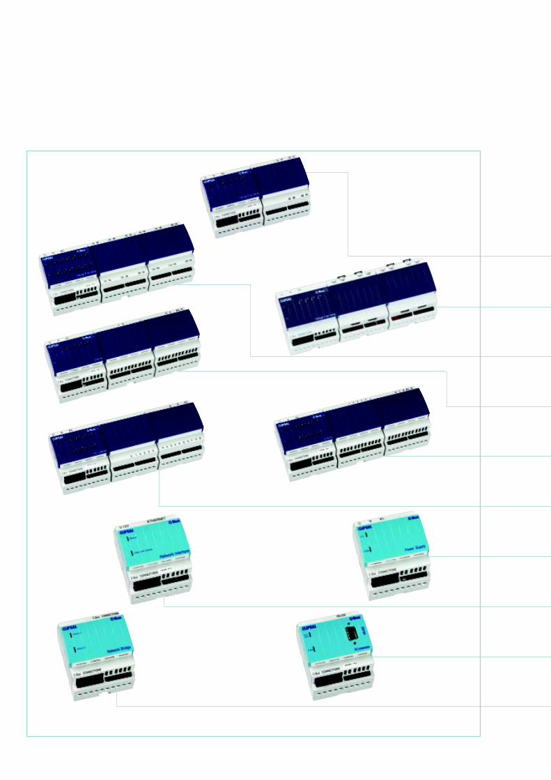
Designed for easy installation and fast programming, C-Bus2 DIN Rail Units are made to fitsimply into standard sized switchboards.
Learn Enabled L5504RVF Series· 4 Channel Voltage Fee Relay, 250Vac 10A per channel
Learn Enabled L5504RVF20 Series· 4 Channel Voltage Fee Relay, 250Vac 20A per channel
Learn Enabled L5512RVF Series· 12 Channel Voltage Free Relay, 250Vac 10A per channel
Learn Enabled L5504D2A Series· Four Channel Dimmer
Learn Enabled L5508D1A Series· 8 Channel Dimmer, 250Vac 1A per channel
Learn Enabled L5508DSI Series· Eight Channel DSI Fluorescent Dimmer
Power Supply 5500PS· Power Supply, 350mA
5500CN· C-Bus Network Interface
5500PC· C-Bus PC Interface
5500NB· C-Bus Network Bridge
C-Bus2 Learn EnabledDIN Rail Units
These architectural dimmers have been specially developed for highpower lighting applications. C-Bus2 Professional Series Dimmerscreate dramatic lighting effects in auditoriums, conference centres,hotels and theatres.
Learn Enabled L5104D5· Four Channel 5A Professional Dimmer
Learn Enabled L5102D10· Two Channel 10A Professional Dimmer
Learn Enabled L5101D20· One Channel 20A Professional Dimmer
· Learn Enabled· Can be software programmed to function as on/off switches, dimmers or timers· Programmable LED status indicators· Only requires a C-Bus2 cable connection - mains power is not required· 4 gang ‘Scene Setting’ version also available for multiple scene set-up· 4 gang switch with inbuilt infra-red receiver is also available (for use with Hand Held
Remote Controller)
· Learn Enabled· Indoor and outdoor passive infrared (IP66) models· All functions separately adjustable and programmable· Programmable LED indicators· Walk test light indicator· Sensitivity and light level adjustment· Integrated light level sensor, sunset switch and security modes· Indoor ultrasonic version and combined ultrasonic and passive
infra-red indoor version
C-Bus2 Professional Series Dimmers
Key Input units come in a wide range of styles and finishes includingmetallic, with plain or engraved face plates. 1, 2 or 4 gang switches areaccommodated in standard sized wall plates. Other features include:
Programmable Wall MountedKey Input Units
Occupancy Sensors
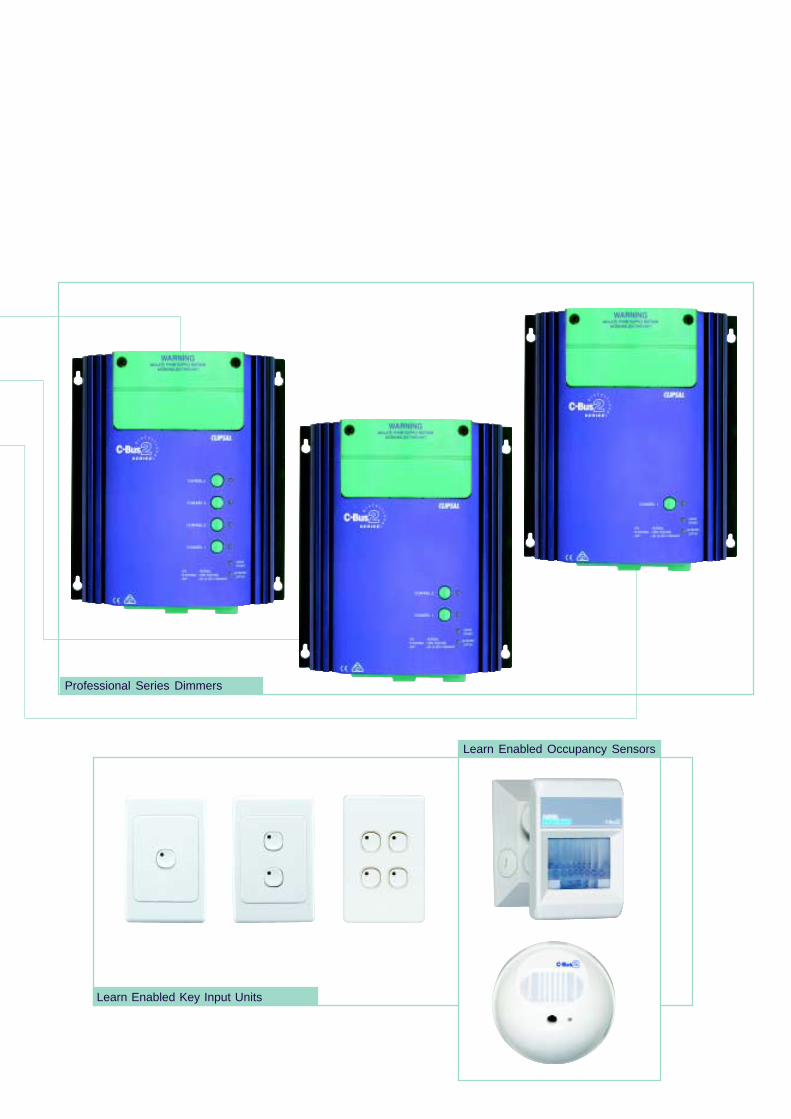
Learn Enabled Key Input Units
Learn Enabled Occupancy Sensors
Professional Series Dimmers
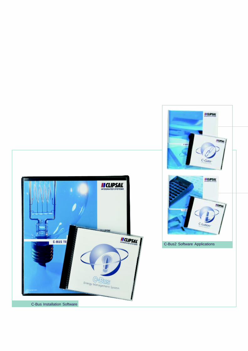
C-Bus Installation Software
C-Bus2 Software Applications
C-Bus2 can use programming and commissioning software tools to group loads in anyrequired combination of switching combinations. The software provides Manual andAutomatic (time based) control for users who want to control the system via a PC.C-Bus2 runs under Microsoft Windows 95/98 and NT.
C-Gate is the gateway software program which allows third partycompanies to integrate with the C-Bus system. C-Gate serversoftware can be embedded into third party software to automaticallymodel the C-Bus network. Other features include:· C-Gate server is a software platform that monitors and controls
the components of the Clipsal C-Bus system· C-Gate uses the industry standard TCP/IP interface· C-Gate is written in JAVA so it is platform independent
(Windows, Linux, Mac OS, Unix)· C-Gate allows you to connect multiple C-Bus networks across a
TCP/IP backbone.
C-Bus2 Software Tools
C-Gate Software Application
C-Lution is a graphical user interface software application allowingthe user to create sophisticated animation to display the operatingstatus, network layout, and building layout. Other features include:· Provides Graphical C-Bus monitor and control functions· Provides C-Bus data logging· C-Bus users can monitor in real time if a load is On, a load is Off,
or its dimmed level· C-Bus units can be modelled and displayed in any format
C-Lution SoftwareApplication
Controls third party devices that use industry standard 0-10V or 1-10Vdc control voltage (e.g., electronic controllable fluorescent ballasts).
· Measures from 20 to 3000 Lux· Programmable hysteresis values· Only requires a C-Bus cable connection - mains power is not
required
Four Channel 0-10VAnalogue Output Device
· 10A resistive and inductive switching plus 0-10V dc output· Compact modules for integration within other equipment· Integrated power supplies, override switches and LED status
indicators
Single and Two ChannelRelay Devices
· Measures from 00 to 500C, with adjustable hysteresis· Only requires a C-Bus cable connection - mains power is not
required
· Allows user override for special events and situations· Controls 2 separate C-Bus Channels and includes battery back up· 7 day time control· 42 memory locations· 24 hour time backup· LCD clock display
Light Level Sensor
Temperature Sensor
Time Clock Module
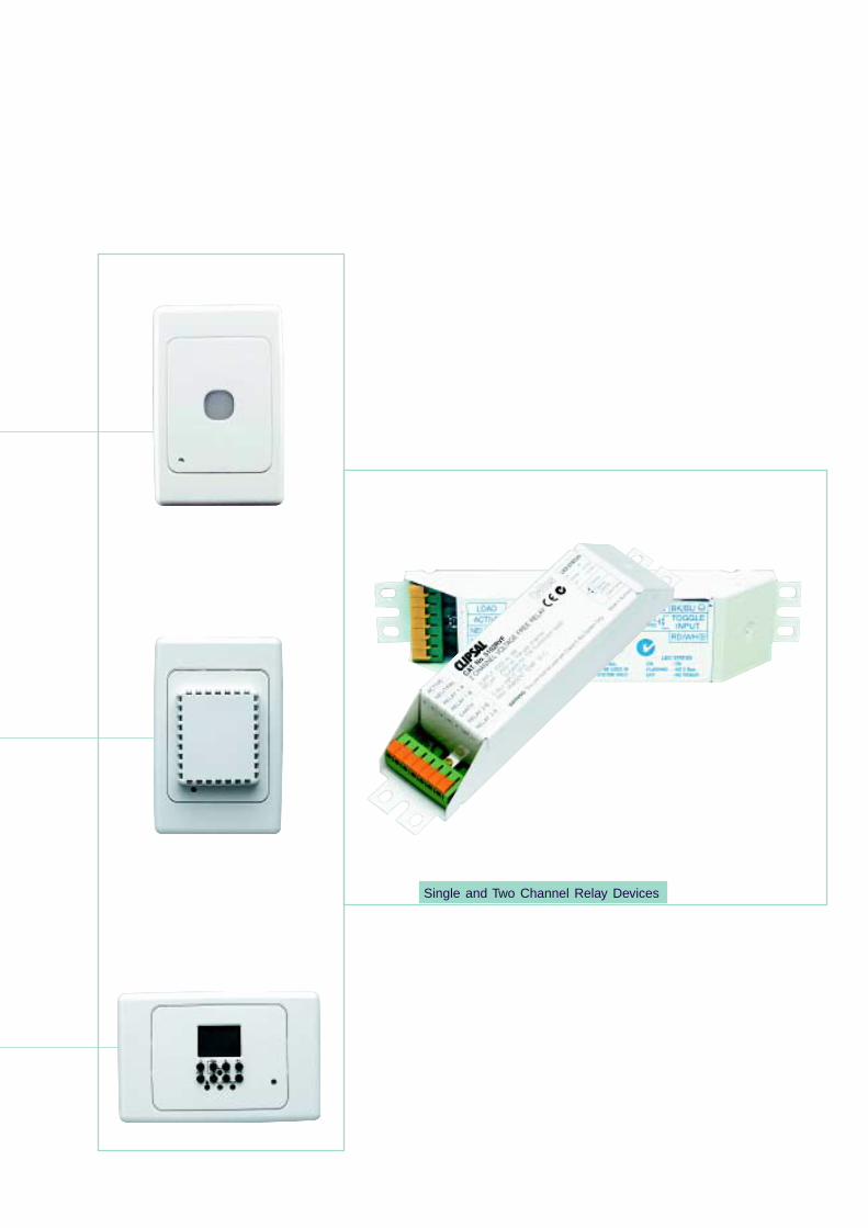
Single and Two Channel Relay Devices
goodto be
2 2 2 2 2
The C-Bus Network
The C-Bus Network Bus is the communications wiring for the system,consisting of an unshielded twisted pair (UTP) ‘Cat 5’ cable. TheNetwork Bus also provides the small amount of power needed tooperate the circuitry within C-Bus units. The C-Bus Network operatesat safe extra low voltage levels (36V dc).
Free Topology Structure
C-Bus devices are wired to any point on the Network by a twistedpair cable. The C-Bus connections may be looped from unit to unit,or a branch can be made at any point. This ‘free topology’ structureprovides a flexible system layout. New units can be added anywhere,at any time, without system re-configuration.
Unlimited Capabilities
A large installation is usually divided into Networks of 100 C-BusUnits, with a total cable length of 1000m per Network. This allows aC-Bus system to be divided into manageable sections, simplifyingdesign, limiting potential fault propagation and aiding in any trouble-shooting.
Peer-To-Peer Communication
Every C-Bus Unit is assigned a unique name, so that all the deviceson the C-Bus Network can communicate directly. Every device onthe C-Bus Network issues and responds to commands directly fromthe Network, rather than requiring a central computer or controller.
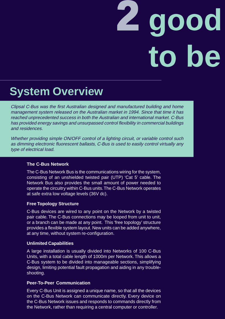
Clipsal C-Bus was the first Australian designed and manufactured building and homemanagement system released on the Australian market in 1994. Since that time it hasreached unprecedented success in both the Australian and international market. C-Bushas provided energy savings and unsurpassed control flexibility in commercial buildingsand residences.
Whether providing simple ON/OFF control of a lighting circuit, or variable control suchas dimming electronic fluorescent ballasts, C-Bus is used to easily control virtually anytype of electrical load.
System Overview
true!
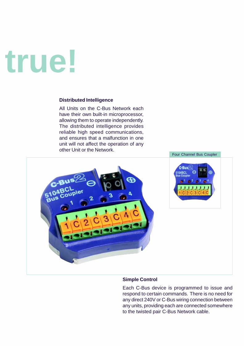
Four Channel Bus Coupler
Distributed Intelligence
All Units on the C-Bus Network eachhave their own built-in microprocessor,allowing them to operate independently.The distributed intelligence providesreliable high speed communications,and ensures that a malfunction in oneunit will not affect the operation of anyother Unit or the Network.
Simple Control
Each C-Bus device is programmed to issue andrespond to certain commands. There is no need forany direct 240V or C-Bus wiring connection betweenany units, providing each are connected somewhereto the twisted pair C-Bus Network cable.
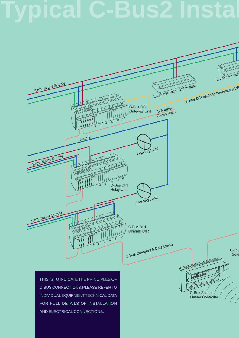
THIS IS TO INDICATE THE PRINCIPLES OF
C-BUS CONNECTIONS. PLEASE REFER TO
INDIVIDUAL EQUIPMENT TECHNICAL DATA
FOR FULL DETAILS OF INSTALLATION
AND ELECTRICAL CONNECTIONS.
Typical C-Bus2 Instal
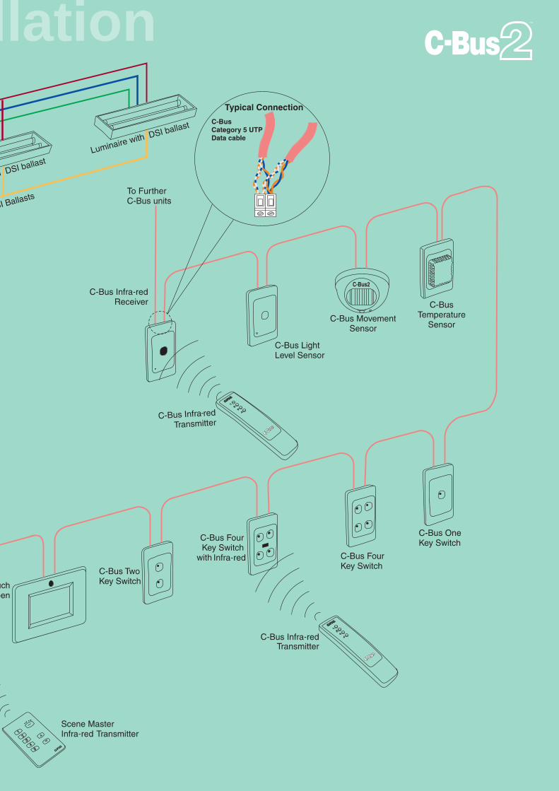
llation

Notes
Products ofClipsal Integrated Systems Pty LtdABN 15 089 444 931
Head Office12 Park Terrace, BowdenSouth Australia 5007
PO Box 103 HindmarshSouth Australia 5007Telephone (08) 8269 0560International +61 8 8269 0560
Facsimile (08) 8346 0845International +61 8 8346 0845
Internet www.clipsal.com/cisE-Mail [email protected]
Offices in all States
NSW Sydney (02) 9794 9200Albury (02) 6041 2377
VIC Melbourne (03) 9207 3200Country Areas 1800 653 893
QLD Brisbane (07) 3244 7444Townsville (07) 4729 3333
SA Adelaide (08) 8269 0555
WA Perth (08) 9442 4444
TAS Hobart (03) 6272 3177Launceston (03) 6343 5900
NT Darwin (08) 8947 0278
International Enquiries
Head Office Export DepartmentTelephone +61 8 8269 0587Facsimile +61 8 8340 7350E-Mail [email protected]
New ZealandClipsal Industries (NZ) Ltd (Auckland)Telephone +64 9 576 3403Facsimile +64 9 576 1015E-Mail [email protected]
Customer ServiceFree Facsimile (0508) 250 305Auckland/Mobile Phone (09) 572 0014Free Phone (0508) CLIPSAL
2547725
MalaysiaClipsal Integrated Systems (M) Sdn BhdLevel 3, Unit 3-2, C P TowerJalan Damansara46350 Petaling JayaTelephone +61 603 7665 3555Facsimile +61 603 7665 [email protected]
SingaporeCIS Pte Ltd (Singapore)No. 8, Jurong Town Hall Road#24-05-06 The JTC SummitSingapore 609434Telephone +65 266 1998Facsimile +65 266 [email protected]
International Representatives
ChinaClipsal China LtdTelephone +86 755 246 1122
GreeceClipsal Hellas S.A.Telephone +30 1 993 9165
Hong KongClipsal Integrated Systems (HK) LimitedTelephone +852 2 487 0261
South AfricaClipsal South Africa (Pty) LtdTelephone +27 11 314 5200
TaiwanClipsal (Taiwan) Co LtdTelephone +886 2 2558 3456
ThailandClipsal Thailand LtdTelephone +66 2 952 5338
United KingdomClipsal Ltd (UK)Telephone +44 1494 521 111
O/N 0270 Nov 01/02
©Copyright Clipsal Integrated Systems Pty LtdPrinted by Custom Press Pty Ltd (08) 8346 7999
Clipsal Integrated Systems Pty Ltd reserves the rightto change specifications, modify designs anddiscontinue items without incurring obligation andwhilst every effort is made to ensure that descriptions,specifications and other information in this catalogueare correct, no warranty is given in respect thereofand the company shall not be liable for any errortherein.
You can find this brochure and manyothers online in PDF format at:clipsal.comFollow the links off the home page oraccess the following page directly:clipsal.com/wat_lib_pdf.cfm
clipsal.com/cis