contributed pap e r singlecarriermodulationwith ...kk/dtsp/tutoriaalit/benvenuto.pdf · pap e r...
TRANSCRIPT

CONTRIBUTEDP A P E R
Single Carrier Modulation WithNonlinear Frequency DomainEqualization: An Idea WhoseTime Has ComeVAgainIn high-speed single-carrier digital communication systems,
processing blocks of signals using Fast Fourier Transforms is an efficient way to
equalize (compensate) for interference between transmitted symbols.
By Nevio Benvenuto, Senior Member IEEE, Rui Dinis, Member IEEE,
David Falconer, Life Fellow IEEE, and Stefano Tomasin, Member IEEE
ABSTRACT | In recent years single carriermodulation (SCM) has
again become an interesting and complementary alternative to
multicarrier modulations such as orthogonal frequency division
multiplexing (OFDM). This has been largely due to the use of
nonlinear equalizer structures implemented in part in the
frequency domain by means of fast Fourier transforms,
bringing the complexity close to that of OFDM. Here a nonlinear
equalizer is formed with a linear filter to remove part of
intersymbol interference, followed by a canceler of remaining
interference by using previous detected data. Moreover, the
capacity of SCM is similar to that of OFDM in highly dispersive
channels only if a nonlinear equalizer is adopted at the receiver.
Indeed, the study of efficient nonlinear frequency domain
equalization techniques has further pushed the adoption of
SCM in various standards. This tutorial paper aims at providing
an overview of nonlinear equalization methods as a key
ingredient in receivers of SCM for wideband transmission. We
review both hybrid (with filters implemented both in time and
frequency domain) and all-frequency-domain iterative struc-
tures. Application of nonlinear frequency domain equalizers to
a multiple input multiple output scenario is also investigated,
with a comparison of two architectures for interference
reduction. We also present methods for channel estimation
and alternatives for pilot insertion. The impact on SCM
transmission of impairments such as phase noise, frequency
offset and saturation due to high power amplifiers is also
assessed. The comparison among the considered frequency
domain equalization techniques is based both on complexity
and performance, in terms of bit error rate or throughput.
KEYWORDS | Decision-feedback equalizers; digital modulation;
discrete Fourier transforms; multiple antennas
I . INTRODUCTION
EqualizationVthe compensation of the linear distortion
caused by channel frequency selectivityVis an essential
component of digital communications systems whose data
symbol rate is higher than the coherence bandwidth of
typically encountered channels. Intersymbol interference
that afflicts serial data transmission has traditionally been
mitigated by equalization implemented in the time domainwith linear filtering, usually with a transversal structure,
hence the designation linear equalizer [1]. Due to the
tradeoff between equalization of the channel impulse re-
sponse to remove intersymbol interference (both pre-
cursors and postcursors) and noise enhancement at the
decision point, a linear equalizer yields less than ideal
performance in terms of bit error rate, especially in
Manuscript received March 25, 2008; revised January 29, 2009. Current version
published December 23, 2009.
N. Benvenuto and S. Tomasin are with the Department of Information Engineering,
University of Padova, Italy (e-mail: [email protected]; [email protected]).
R. Dinis is with IT (Instituto das Telecomunicaçoes) and FCT-UNL
(Faculdade de Ciencias e Tecnologia da Universidade Nova de Lisboa), Lisbon, Portugal
(e-mail: [email protected]).
D. Falconer is with the Department of Systems and Computer Engineering,
Carleton University, Ottawa, Canada (e-mail: [email protected]).
Digital Object Identifier: 10.1109/JPROC.2009.2031562
Vol. 98, No. 1, January 2010 | Proceedings of the IEEE 690018-9219/$26.00 �2010 IEEE
Authorized licensed use limited to: Oulu University. Downloaded on January 14, 2010 at 08:18 from IEEE Xplore. Restrictions apply.
dispersive channels. Other types of equalizers have there-fore been proposed, especially ones with a nonlinear
structure denoted as decision feedback equalizer (DFE),
where, after a first transversal filter aiming at reducing the
precursors of the equivalent pulse at the detection point, a
linear feedback filter, whose input is the sequence of past
detected data symbols, removes by cancellation the inter-
symbol interference due to postcursors. Hence, the struc-
ture is nonlinear with respect to the received signal.Indeed, due to the feedback of detected data symbols, the
DFE is hard to analyze. However in general, its perfor-
mance is much better than that of a linear equalizer and
can come close to that of an optimum sequence detector,
e.g., implemented by the Viterbi algorithm, for a much
lower complexity [2].
The signal processing complexity (number of arithme-
tic operations per data symbol) in time domain equaliza-tion, exemplified by the number of transversal filter tap
coefficients, increases at least linearly with the number of
data symbol intervals spanned by the channel impulse
response. Frequency domain processing of blocks of signals,
using discrete Fourier transforms (DFT), provides lower
complexity per data symbol, and has therefore recently
emerged as the preferred mitigation approach to channel
frequency selectivity, for next-generation broadband wire-less systems with bit rates of tens or hundreds of megabits/s.
In this overview paper, we survey frequency domain equal-
ization structures, mostly based on the DFE principle, for
single carrier wireless digital transmissions.
Serial or single carrier modulation (SCM), in which
data symbols are transmitted in serial fashion, has been
the traditional digital communications format since the
early days of telegraphy. An alternative is multicarriertransmission, where multiple data streams, each modu-
lating a narrowband waveform, or tone, are transmitted in
parallel, thus allowing each tone to be separately equalized
by a simple gain and phase factor. Multicarrier transmis-
sion has become popular and widely used within the last
two decades, due mainly to its excellent complexity/
performance tradeoff for data symbol rates far above
coherence bandwidths, and also for its flexible linkadaptation ability [3]–[5]. Among the first military and
commercial multicarrier systems were the Collins Kineplex
and General Atronics KATHRYN HF radio systems [6], [7]
of the 1950s and 1960s. The KATHRYN system used DFT
signal processing at the transmitter and receiver. With the
realization that the eigenvectors of a linear system are
sinusoids, multicarrier transmission was recognized as an
optimal format for frequency selective channels in the early1960s [8], [9]. Generation and block processing of
multicarrier signals in the frequency domain, are enor-
mously simplified by implementing the DFTs by fast
Fourier transforms (FFTs), as was recognized by Weinstein
and Ebert in 1971 [10], yielding a signal processing
complexity that grows only logarithmically with the channel
impulse response length. This realization, and the ever-
growing demand for higher data rates on wireless and wiredsystems propelled the application of multicarrier transmis-
sion to i) digital subscriber line transmission standards,
where it is generally known as discrete multitone transmission,
ii) IEEE 802.11a wireless LAN and iii) digital audio and video
broadcast standards, where it is known as orthogonalfrequency division multiplexing (OFDM), or orthogonalfrequency division multiple access (OFDMA). The early
success of OFDM in standards after more then twenty yearssince the pioneering implementations, has been marked by
Bingham in his landmark paper: Multicarrier modulation fordata transmission: an idea whose time has come, [3].
A related development in the early 1970s was the
realization that frequency domain processing techniques
could also be used to facilitate and simplify equalization of
SCM systems [11]. More recently, as an alternative to the
first OFDM applications in wireless standards, Sari et al.[12]–[14] pointed out that traditional SCM could enjoy an
implementation simplicity/performance tradeoff similar to
that of OFDM for highly frequency selective channels with
the inverse DFT moved at the receiver. (A simpler struc-
ture, with applications to diversity reception, was proposed
by Clark [15] a few years later.) Indeed, this is true only for
a nonlinear frequency domain equalizer. In fact, only the
performance of a DFE can come close to or even exceedthat of OFDM [16]. SCM waveforms have the additional
advantage that for a given signal power their range of
amplitude, measured by the peak-to-average ratio, is signif-
icantly less than that of multicarrier signals. As a result,
their transmitted spectra and performance are less affected
by transmitter power amplifier nonlinearities. This allows
cheaper and more efficient high power amplifiers to be
used for transmitting SCM signals. A further benefit ofSCM is its greater robustness to frequency offset and phase
noise than that of OFDM [17] (see also [18]).
These features of robustness to radio frequency hard-
ware impairments make single carrier with frequency
domain equalization an attractive alternative to OFDM,
especially for cost- and power consumption-sensitive next-
generation wireless user terminals which transmit uplink
to base stations [19]. Thus frequency domain implementa-tions of SCM receivers can be said to be an idea whose time
has come again after a hiatus of about 20 years. However
the status of SCM now is not that of a potential replacementof OFDM, but rather of a complement to it. As we will see,
traditional SCM can morph to a special form of multicarrier
transmission, which can be called DFT-precoded OFDM. As
such, it is a form of generalized multicarrier transmission
[20] (see also [21] and [22]).SCM in the form of DFT-precoded OFDM has been pro-
posed by the European 6th framework program WirelessINitiative NEw Radio (WINNER) project as the uplink trans-
mission format for wide area cellular scenarios, mainly on
the basis of its radio frequency impairment robustness
properties. WINNER downlink and local area uplink trans-
missions rely on OFDMA, mainly because of its flexibility
Benvenuto et al.: An Idea Whose Time Has ComeVAgain
70 Proceedings of the IEEE | Vol. 98, No. 1, January 2010
Authorized licensed use limited to: Oulu University. Downloaded on January 14, 2010 at 08:18 from IEEE Xplore. Restrictions apply.

and transmission channel adaptability properties [23]. TheThird Generation Partnership ProjectVLong Term Evolution(3GPP-LTE) and now LTE-Advanced standards group also
propose DFT-precoded OFDM, which they call single carrierfrequency division multiple access for the uplink of next-
generation wide area cellular broadband wireless systems,
again with OFDMA used in the downlink [24], [25]. These
initiatives and standards activities are contributing to the
International Mobile Telecommunications Advanced (IMT-Advanced) initiative of the International Telecommunica-
tions Union. The 802.16m Task Group of the IEEE 802.16
Wireless metropolitan area network standards group has
recently been formed to contribute to IMT-Advanced. At the
time of writing, its proposed standard has not been finalized,
but versions of single carrier frequency domain equalization,
as well as OFDM, have been considered for uplinks. The
earlier 802.16a standard, which led to the WiMAX wirelessmetropolitan area concept, has three transmission modes:
two based on versions of OFDM and one based on SCM.
The rest of the paper is organized as follows. In Section II
we provide the basic principles and signal structure of SCM
frequency domain nonlinear equalization. In Section III, we
present various nonlinear equalization techniques imple-
mented in the frequency domain for a single antenna system
and using the direct knowledge of the channel frequencyresponse. These structures will be extended to the case of
transmitters and receivers with multiple antennas in
Section IV, where we also describe an iterative equalizer
fully implemented in the frequency domain. Channel
estimation methods for the proposed structures are investi-
gated in Section V. Impacts of phase noise and other
disturbances on implementations of the nonlinear frequency
domain equalizers are considered in Section VI. Section VIIcompares SCM with OFDM, with a focus of the considered
nonlinear frequency domain equalization structures. Lastly,
conclusions are outlined in Section VIII.
Notation: � denotes the complex conjugate, T denotes
the transpose, H denotes the Hermitian (transpose and
complex conjugate) operator. The DFT of sequence fsng,n ¼ 0; 1; . . . ; P� 1, is
Sp ¼XP�1
n¼0
sne�j2�npP ; p ¼ 0; 1; . . . ; P� 1: (1)
The inverse DFT (IDFT) of sequence fSpg, p ¼ 0;1; . . . ; P� 1, is
sn ¼1
P
XP�1
p¼0
Spej2�npP ; n ¼ 0; 1; . . . ; P� 1: (2)
IN denotes the N � N identity matrix. Circular convolution
among signals x and y is denoted as ðx� yÞ.
II . SYSTEM DEFINITIONS AND THEFINGERPRINT OF SINGLE CARRIERFREQUENCY DOMAIN EQUALIZER:TRANSMISSION FORMAT
A wireless mobile transmission is characterized by a slowly
time-varying multipath channel between each pair of
transmit and receive antennas in a multiple input-multiple
output (MIMO) scenario. For a system with NT transmit
and NR receive antennas, we denote the impulse response
of the time-invariant channel from antenna i to antenna jas h
ðj;iÞCh ð�Þ, i ¼ 1; 2; . . . ;NT, j ¼ 1; 2; . . . ;NR. Upon trans-
mission of signal �s ðiÞðtÞ from antenna i, the received signal
at antenna j can be written as (baseband equivalent model)
�rðjÞðtÞ ¼XNT
i¼1
Zhðj;iÞCh ð�Þ�s
ðiÞðt� �Þ d� þ wðjÞðtÞ (3)
where �wðjÞðtÞ is the noise term, which we assume to be
complex Gaussian with zero mean and power spectral
density N0.
Traditionally, a SCM signal is generated as a
sequential stream of data symbols, at regular time instants
nT, for n ¼ . . . ; 0; 1; 2; . . ., where T is the data symbol
interval, and 1=T is the symbol rate. Although generally
receivers perform oversampling, for the sake of a simplernotation, we assume also that the received signal is
filtered and sampled with rate 1=T. Hence we describe the
transmission system by an equivalent discrete-time model
where the channel is characterized by the impulse
response hðj;iÞ‘ , ‘ ¼ 0; 1; . . . ;Nh � 1, obtained by sampling
the cascade of the transmit filter, the channel and the
receive filter. By indicating with sðiÞn the symbol transmit-
ted from the ith antenna, the received signal after samp-ling can be written as
rðjÞn ¼XNT
i¼1
XNh�1
‘¼0
hðj;iÞ‘ s
ðiÞn�‘ þ wðjÞn (4)
where wðjÞn is the noise term with variance �2w.
In order to allow frequency domain block equalizationof the received signal, the convolutions in (4) must be
circular and this can be achieved in different ways.
As we will first consider the single input-single output
case, we drop the antenna index for sake of a simpler
notation. The MIMO case is considered in Section IV.
A. Circular and Linear ConvolutionThe transmitted signal fsng depends on the informa-
tion signal fdng but, in general, the two may not coincide.
We examine conditions such that each linear convolution
in (4) appears as a circular convolution between the
Benvenuto et al.: An Idea Whose Time Has ComeVAgain
Vol. 98, No. 1, January 2010 | Proceedings of the IEEE 71
Authorized licensed use limited to: Oulu University. Downloaded on January 14, 2010 at 08:18 from IEEE Xplore. Restrictions apply.

channel impulse response and the information datasignals dn.
Let us consider the sequence of data symbols in blocks
of M, fdng, n ¼ 0; 1; . . . ;M� 1; and the Nh-size sequence
fhng, n ¼ 0; 1; . . . ;Nh � 1, with M > Nh. We define the
periodic signals of period P, drepP;n ¼ dðn mod PÞ, and
hrepP;n ¼ hðn mod PÞ, n ¼ 0; 1; . . . ; P� 1, where in order to
avoid time aliasing, P � M and P � Nh.
Now, the circular convolution between fdng and fhngis a periodic sequence of period P defined as
xðcircÞn ¼ ðh� dÞn ¼
XP�1
‘¼0
hrepP;n�‘drepP;‘: (5)
Then, if we indicate with fDpg, fHpg and fXðcircÞp g,
p ¼ 0; 1; . . . ; P� 1, the P-point DFT of sequences fdng,n ¼ 0; 1; . . . ; P� 1, fhng, and fxðcircÞ
n g, n ¼ 0; 1; . . . ; P� 1,
respectively, we obtain
XðcircÞp ¼ HpDp; p ¼ 0; 1; . . . ; P� 1: (6)
The linear convolution with support n ¼ 0; 1; . . . ; MþNh � 2 is
xðlinÞn ¼XNh�1
‘¼0
h‘dn�‘: (7)
By comparing (7) with (5), it is easy to see that only if
P � Mþ Nh � 1, then
xðlinÞn ¼ xðcircÞn ; n ¼ 0; 1; . . . ; P� 1: (8)
To compute the convolution between the two finite-length
sequences fdng and fhng, (8) requires that both sequences
be completed with zeros (zero padding) to get a length of
P ¼ Mþ Nh � 1 samples. Then, taking the P-point DFT ofthe two sequences, performing the product (6), and taking
the inverse transform of the result, one obtains the desired
linear convolution.
However, there are other conditions, some of which are
listed below, that yield a partial equivalence between the
circular convolution fxðcircÞn g and the linear convolution
xn ¼XNh�1
‘¼0
h‘sn�‘; (9)
where fsng depends on fdng.
Overlap and Save: We consider as the transmitted signalsn ¼ dn, n ¼ 0; 1; . . . ;M� 1 and assume P ¼ M. We verify
that (9) coincides with (5) only for the instants n¼Nh�1,
Nh; . . . ;M� 1, [26]. In other words, the equivalence
between the linear and the circular convolution holds
always on a subset of the computed points.
Cyclic Prefix: An alternative to overlap and save is to
consider, instead of the transmission of the data sequencefdng, an extended sequence fsng that is obtained by
partially repeating fdng with a cyclic prefix of L � Nh � 1
samples, [26]:
sn ¼dn n ¼ 0; 1; . . . ;M� 1
dMþn n ¼ �L; . . . ;�2;�1.
�(10)
Moreover, assume P ¼ M. It is easy to prove that (9)
coincides with (5) for n ¼ 0; 1; . . . ;M� 1. Moreover, the
equivalence (6) in the frequency domain holds for DFTs ofsize P ¼ M, the data block size. This arrangement is used
also in multicarrier communications [11].
Pseudo Noise (PN) Extension: Consider a sequence fsng,obtained by fdng with the addition of a fixed sequence pn,
n ¼ 0; 1; . . . ; L� 1, of L � Nh � 1 samples, i.e.,
sn ¼dn n ¼ 0; 1; . . . ;M� 1
pn�M n ¼ M; . . . ;Mþ L� 1.
�(11)
The first data block is also preceded by the sequence fpng.Moreover, now P ¼ Mþ L. The sequence fpng can contain
any symbol sequence, including all zeros (zero padding)
[27], [28], or a PN symbol sequence, denoted PN extension
or unique word. The choice of the extension is also influ-
enced by other factors, such as channel estimation [29]. It
can be easily proved, that (9) coincides with ðh� sÞn for
n ¼ 0; 1; . . . ; P� 1, where now the circular convolution ison sn instead of dn.
With reference to the noisy MIMO scenario (4), we can
organize the transmitted signal fsng into blocks of size P,
each obtained by extending with a PN sequence a data block
of size M. Moreover, at the beginning a PN sequence is
transmitted first. Let fsnþkPg, n ¼ 0; 1; . . . ; P� 1 be the kth
block and let fHðj;iÞp g be the P-size DFT of the channel
impulse response fhðj;iÞ‘ g. Then we obtain
RðjÞp ðkÞ ¼XNT
i¼1
Hðj;iÞp SðiÞp ðkÞ þWðjÞp ðkÞ;
p ¼ 0; 1; . . . ; P� 1 (12)
where WðjÞp ðkÞ is the noise term in the frequency domain,
which according to the hypothesis on fwng is i.i.d. with
Benvenuto et al.: An Idea Whose Time Has ComeVAgain
72 Proceedings of the IEEE | Vol. 98, No. 1, January 2010
Authorized licensed use limited to: Oulu University. Downloaded on January 14, 2010 at 08:18 from IEEE Xplore. Restrictions apply.

variance �2W ¼ P�2
w. Note that in this arrangement theDFTs are of size P ¼ Mþ L instead of size M as in the cyclic
prefix arrangement. Moreover, in this arrangement, an
additional PN extension is required before the first data
block. Among the advantages of this format are a simple
channel estimation, by using the PN sequence [29], and the
possibility of implementing an efficient frequency domain
(FD) nonlinear equalizer, as detailed in Section III. Gen-
erally, the PN extension yields a reduced bit error rate withrespect to the cyclic prefix, since in the latter case data
detection errors affect both the information data and the
cyclic prefix, thus reducing the intersymbol interference
cancellation capabilities of the nonlinear equalizer. In the
following we will consider operations on a single data block
and we will drop the index k from FD signals.
B. Signal GenerationAs described in the previous section, the data symbol
sequence may be organized into DFT blocks, which may
include PN extensions, or to which cyclic prefixes areappended, thus facilitating DFT processing and FD
equalization at the receiver. The resulting data sequences,
with or without extensions and prefixes, are low pass
filtered for bandlimiting and spectrum-shaping purposes,
before being up-converted to the carrier frequency.
Fig. 1 shows a generalized multicarrier transmitter archi-
tecture [19], [20], [22], which can be adapted to generate a
wide variety of signals, including SCM signals, as well asOFDM, OFDMA, multicarrier code division multiple access
(CDMA), etc. Because its processing occurs in the FD, it is
easy to generate signals with arbitrary spectra, and to insert
FD pilot tones for channel estimation (see Section V). Com-
plexity is not a major issue since processing is done with
DFTs and IDFTs, implemented by FFTs. In the figure, the
IDFT block is preceded by a general pre-matrix operation,
which may include a DFT, spreading, a selection mechanismand/or an allocation to multiple transmitting antennas in a
MIMO or space-time code. Recognition of this generalized
structure can also be found in [30]–[32].
Generation of a SCM signal block proceeds as follows.
After coding and serial to parallel (S/P) conversion, blocks
of N coded data symbols are mapped to the FD by a N-pointDFT. The resulting FD data components are mapped by the
pre-matrix time-frequency-space selector to a set of M � Ndata-carrying subcarriers, and then processed by a
M–point inverse DFT to convert back to the time domain
(TD). The resulting samples are parallel-to-serial (P/S)
converted and appended with a prefix or extension for
transmission. The simplest frequency mapping is to Ncontiguous subcarrier frequencies, with the remainingM� N being padded with zeroes. In this case, the output
samples are expressed as
sn¼1
M
XN�1
‘¼0
d‘XN�1
p¼0
ej2�p n�‘MNð Þ
M
¼XN�1
‘¼0
g n� ‘M
N
� �d‘; n¼0; 1; . . . ;M�1 (13)
where
gðnÞ ¼ ej2�ðN�1Þn
M1
M
sin �NnM
� �sin �n
M
� � (14)
while fsng, n ¼ �L;�Lþ 1; . . . ;�1, contains the cyclicprefix.
This is recognized as a block of data symbols serially
transmitted at intervals of M=N samples. The sampled
pulse waveform given by (14) is a circular version of a sinc
pulse with zero excess bandwidth, limited to a bandwidth
N=MT. SCM signals generated in this way are called DFT-precoded OFDM signals by the WINNER project [23], and
local single carrier FDMA (SC-FDMA) by the 3GPP-LTEstandards body [24], [25]. For (13), smM=N ¼ N=Mdm, thus
the DFT-precoded OFDM waveform at data symbol inter-
vals depends only on a single data symbol, and therefore
has a significantly lower peak to average power ratio than
that of a corresponding OFDM waveform, whose sample
Fig. 1. Generalized multicarrier transmitter (from [22]).
Benvenuto et al.: An Idea Whose Time Has ComeVAgain
Vol. 98, No. 1, January 2010 | Proceedings of the IEEE 73
Authorized licensed use limited to: Oulu University. Downloaded on January 14, 2010 at 08:18 from IEEE Xplore. Restrictions apply.

values are equally weighted sums of all N data symbols. Itis important to recognize that this form of DFT-precoded
OFDM signal is a SCM. The transmitter can be designed to
generate it in this FD fashion, or in the conventional TD
fashion, with serial transmission and pulse shaping.
Variations of this procedure abound for different
desired signal formats. For example, aliased copies of the
data block can be created and windowed with a square root
raised cosine window to yield a filtered waveform with agiven excess bandwidth or rolloff factor. If the initial DFT
operation is omitted, a bandlimited OFDM waveform is
produced. If the DFT is omitted and the N data symbols are
mapped to a noncontiguous set of subcarrier frequencies,
the result is an OFDMA signal. In this way, certain
frequency subbands known to contain signals from other
transmitters or to undergo severe fading, can be avoided
and efficient frequency division multiplexing of multipleuser signals is facilitated. The time-frequency-space se-
lector can distribute data-carrying components to different
transmitting antennas as well as to different frequencies in
space-frequency block coding schemes [33].
Non-contiguous mapping can also be used for DFT-
precoded signals, for example to allow in-band pilot tones
to be inserted without interfering with data, or to spread
data over a wider bandwidth to enhance frequency diver-sity. A SCM and multiple access scheme sometimes called
interleaved frequency domain multiple access (IFDMA)
[34], can be generated from Fig. 1, by mapping N DFT
outputs from each of up to U users onto N frequencies
which are spaced at intervals of U subcarriers. User uðu ¼ 0; 1; . . . U � 1Þ is assigned to the frequency set
fu; uþ U; uþ 2U; . . . ; uþ ðN � 1ÞUg. Each user thus
occupies a unique set of N frequencies in an interleavedfashion. For M > UN, the waveform corresponding to (14)
is, for the uth user,
sn;u ¼ ej2�unM
XN�1
‘¼0
gIFDMA n� ‘ M
UN
� �d‘;u;
n ¼ 0; 1; . . . ;M� 1 (15)
where
gIFDMAðnÞ ¼ ej2�UðN�1Þn
M1
M
sin �UNnM
� �sin �Un
M
� � ;n ¼ 0; 1; . . . ;M� 1: (16)
In an uplink scenario, each user transmits fsn;ug as in (15),
where fsn;ug, n ¼ �L; . . . ;�1, contains the cyclic prefix.
The waveform described by (16) has periodic peaks at
n ¼ 0; ðM=UÞ; 2ðM=UÞ; . . . ; ðU � 1ÞðM=UÞ, but in (15)
smM=U;u¼ðUN=MÞej2�ðum=UÞdm mod N;u, m¼0; 1; . . . ;UP� 1.
Thus again the low peak to average power ratio property is
preserved. It is clear that U IFDMA signals generated in theFD this way preserve their orthogonality independent of
their channels’ frequency selectivities, since they are
frequency-disjoint. Furthermore, each such signal is spread
in frequency by a factor of U, which yields a significant
frequency diversity advantage. The IFDMA waveform can
also be generated in the TD [35]. A generalization of
IFDMA is block IFDMA, where each user is assigned
multiple blocks of adjacent subcarriers and blocks belong-ing to different users are interleaved [36].
If NP pilot tones are to be inserted at frequencies
0;U; 2U; . . . ; ðNP � 1ÞU, with data-carrying tones being
displaced to make room for them, the set of frequencies
used for data is fp ¼ 1; 2; . . . ; ðU � 1Þ; ðU þ 1Þ; ðU þ 2Þ;. . . ð2U�1Þ; ð2U þ 1Þ; . . . ; ðN � 1þ NPÞg. In this case the
DFT-precoded OFDM data waveform, not including the
added pilot tones, can be shown to be [37]
sn ¼P
ðU � 1ÞNPMej�Nn
M
XN�1
‘¼0
gðn; ‘Þd‘ej�ðN�1Þ‘
N ;
n ¼ 0; 1; . . . ;M (17)
where
gðn; ‘Þ ¼sin �NP
UnM �
ðU�1Þ‘P
� �� �sin � Un
M �ðU�1Þ‘
P
� �� � sin ðU � 1Þ nM� ‘
P
� �� �sin n
M� ‘P
� �� � :
(18)
This expression is not that of a pure SCM signal. Howeveras will be seen later in Section VI, its peak to average
power ratio properties are favorable in comparison to those
of corresponding OFDM waveforms.
Fig. 2 shows the general receiver structure for
generalized multicarrier signals. The first element is a
DFT operation, followed by a selector (or sampler) if nec-
essary, and an equalizing FD filter. The linear operation
after channel equalization depends on the transmitter’sprematrix operation: detection and decoding for OFDM or
OFDMA, a correlation operation for multicarrier CDMA,
an IDFT for SCM, etc.
III . DIRECT EQUALIZATION METHODS
Various equalization structures whose parameters are
designed directly from an estimate of the channel frequency
response will be presented in this section. In particular, we
will assume that the exact channel frequency response is
available. In Section V we will consider techniques for
channel estimation. Moreover, a comparison in terms of
performance and computational complexity is given. The
Benvenuto et al.: An Idea Whose Time Has ComeVAgain
74 Proceedings of the IEEE | Vol. 98, No. 1, January 2010
Authorized licensed use limited to: Oulu University. Downloaded on January 14, 2010 at 08:18 from IEEE Xplore. Restrictions apply.

computational complexity is evaluated in terms of number of
complex multiplications: for each structure we evaluate the
complexity per data symbol, while for each design methodwe evaluate the complexity per parameter computation. We
assume that a DFT of size P, implemented with FFT, requires
ðP=2Þ log2ðPÞ � P complex multiplications. A synoptic com-
parison of the various equalizers is provided in Table 1.
A. Time Domain Decision Feedback EqualizerIn a conventional TD DFE (TDDFE) no framing is
needed at the transmitter, as operations are performed on
a symbol-by-symbol basis in the TD. In particular, the
received signal frng is filtered by a feedforward filter
fgFF;‘g, ‘ ¼ ��;�� þ 1; . . . ;NFF � 1� � to obtain
zn ¼XNFF�1��
‘¼��gFF;‘rn�‘ (19)
where � is a suitable delay introduced by the feedforward
filter and channel. Detection is performed symbol bysymbol and interference on zn due to past symbols is
removed by the TD feedback filter fb‘g, ‘ ¼ 1; 2; . . . ;NFB,
applied on past detected symbols dn�‘, ‘ ¼ 1; 2; . . . ;NFB.
At the detection point the signal can be written as
~dn ¼ zn þXNFB
‘¼1
b‘dn�‘: (20)
Detection is applied on ~dn to obtain dn. In a direct design
approach, the feedforward and feedback filters are
designed by solving a linear system of equations [2], withcomplexity OðN3
FFÞ complex multiplications. Moreover,
from (19) and (20), the computational complexity of the
TDDFE is NFF þ NFB complex multiplications per data
symbol.
B. Decision Feedback Equalizer With a HybridTime-Frequency Structure
In the hybrid DFE (HDFE), the feedforward filter
operates in the FD on blocks of the received signal, while
the feedback operates in the TD [16], [38]. In order to allow
TD implementation of the feedback filter, data transmis-
sion with a PN extension [see (11)] must be considered
instead of cyclic prefix.As shown in Fig. 3, after the DFT of the received samples,
the feedforward filter, with coefficients fCpg, p ¼ 0; 1; . . . ;P� 1, is applied to yield the block signal fZpg, p ¼ 0; 1; . . . ;P� 1 with elements
Zp ¼ CpRp; p ¼ 0; 1; . . . ; P� 1: (21)
Through the IDFT, the sequence fZpg is then transformed
in the TD to provide the sequence fzng.From the detected data sequence fdng and (11), the
extended detected sequence fsng is given by
sn ¼ dn; n ¼ 0; 1; . . . ;M� 1,
pn�M; n ¼ M;Mþ 1; . . . ; P� 1.
�(22)
Fig. 2. Generalized multicarrier receiver (from [22]).
Table 1 Computational Complexity of Equalizer Structures
Benvenuto et al.: An Idea Whose Time Has ComeVAgain
Vol. 98, No. 1, January 2010 | Proceedings of the IEEE 75
Authorized licensed use limited to: Oulu University. Downloaded on January 14, 2010 at 08:18 from IEEE Xplore. Restrictions apply.

Then, if fb‘g, ‘ ¼ 1; 2; . . . ;NFB, are the coefficients of the
feedback filter, the signal at the input of the decision
element is
~dn ¼ zn þ yn; n ¼ 0; 1; . . . ;M� 1 (23)
and
yn ¼XNFB
‘¼1
b‘ sn�‘ (24)
is the feedback signal. Note that, as indicated in Fig. 3,
for each block the first NFB data symbols, which initializethe feedback part of the DFE, coincide with the PN
symbols fpng.The computational complexity of the HDFE structure
is ðP=MÞ log2ðPÞ þ NFB � ðP=MÞ, as two P-size (I)DFTs
and one multiplication is performed for each block of Mdata symbols, while a feedback filter of size NFB is applied
on the detected data.
Starting from the channel frequency response, two
design methods are outlined: zero forcing and minimum
mean square error (MSE).
Zero Forcing: According to the zero forcing criterion, all
interferers must be canceled by the feedback filter. Firstly,
let the P-size DFT of the feedback filter be fBpg, p ¼ 0;1; . . . ; P� 1. As detailed in [16] the feedforward filter is
simply given by
Cp ¼1
Hpð1� BpÞ: (25)
Let’s define the NFB � NFB Toeplitz matrix AZF having as
first row the first NFB coefficients of the DFT of f1=jHpj2g,p ¼ 0; 1; . . . ; P� 1. Let’s also define the NFB-size columnvector vZF, having as elements the first NFB coefficients of
the IDFT of f1=jHpj2g, p ¼ 0; 1; . . . ; P� 1. Then the
feedback filter that removes interference is the solution of
the linear system AZFb ¼ vZF, [16]. Since AZF is a Toepliz
matrix, the reduced complexity Levinson-Durbin algorithm
[26] can be used to solve the system, with complexity
OðN2FBÞ. Additionally, observe that, if NFB � Nh, the
Fig. 3. The HDFE structure.
Benvenuto et al.: An Idea Whose Time Has ComeVAgain
76 Proceedings of the IEEE | Vol. 98, No. 1, January 2010
Authorized licensed use limited to: Oulu University. Downloaded on January 14, 2010 at 08:18 from IEEE Xplore. Restrictions apply.

elements of both AZF and vZF can be computed as 2NFB-sizeDFTs of f1=jHpj2g.
Minimum Mean Square Error: According to the mini-
mum MSE criterion, the coefficients of the feedforward
and feedback filters are chosen to minimize the sum of the
power of the filtered noise, and the power of the residual
interference. In particular, the MSE at the detection point
is given by
J ¼ E j~dn � dnj2
(26)
which, assuming that pn is i.i.d. with the same statistics of
dn, by the Parseval’s equation becomes in the FD
J ¼ 1
P2EXP�1
p¼0
j~Sp � Spj2" #
: (27)
Then, using (23) in the FD and substituting (12) for Rp and
(24) in the FD for Yp we have
J ¼ 1
P2EXP�1
p¼0
ðCpHp � 1ÞSp � BpSp þ CpWp
�� ��2" #: (28)
By assuming that a) the past detected data symbols are
correct ðSp ¼ SpÞ, b) both noise and data symbols are i.i.d.
and statistically independent of each other, J can bewritten as
J ¼ 1
P2
XP�1
p¼0
CpHp � Bp � 1�� ��2�2
D þ jCpj2�2W (29)
where �2D is the variance of the data in the FD.
Setting the gradient of J with respect to fCpg,p ¼ 0; 1; . . . ; P� 1, to zero, yields the following relation
between feedforward and feedback coefficients [16]
Cp ¼H�pð1� BpÞ
jHpj2 þ �2W
�2D
; p ¼ 0; 1; . . . ; P� 1: (30)
We define now the NFB-size Toeplitz matrix AMMSE whose
first row comprises the first NFB coefficients of the DFT of
f1=ð�2DjHpj2 þ �2
WÞg, p ¼ 0; 1; . . . ; P� 1, and the column
vector vMMSE whose NFB elements are the first NFB
coefficients of the IDFT of f1=ð�2DjHpj2 þ �2
WÞg, p ¼ 0;1; . . . ; P� 1.
By substituting (30) into (29) and setting the gradient
of J to zero with respect to the feedback coefficients b, it is
seen that b is provided by the solution of the linear system
of NFB equations with NFB unknowns AMMSEb ¼ vMMSE.
We note that the complexity of the minimum MSE method
is similar to that of zero forcing. Once the feedback filter is
determined, the feedforward filter is given by (30). Note
that the minimum MSE solution will reduce to the zeroforcing solution when �2
W ! 0.
The computational complexity for the design of HDFE
is reported in Table 2.
C. Frequency Domain Linear EqualizerThe FD linear equalizer with PN extension can be
considered as a particular case of the HDFE, as there is no
feedback filter, i.e., fBp ¼ 0g, p ¼ 0; 1; . . . ; P� 1 in (30).
Moreover, we should note that there exists also a linear FD
equalizer with cyclic prefix whose analysis is easily derivedfrom the HDFE. We recall from the Introduction that the
linear equalizer structure yields less than ideal perfor-
mance in dispersive channels. Hence, although it received
some attention in the recent literature [39], it will not be
considered further in this paper.
D. HDFE With Feedback as a Noise PredictorThe HDFE with feedback as a noise predictor
(HDFE-NP) scheme is illustrated in Fig. 4. If fzng, n ¼0; 1; . . . ; P� 1, is the output of the feedforward filter,implemented in the FD, we form, for n ¼ 0; 1; . . . ;M� 1,
[40], [41]
~zn ¼ zn � sn (31)
yn ¼XNFB
‘¼1
b‘~zn�‘ (32)
~dn ¼ zn þ yn: (33)
To minimize noise and intersymbol interference in ~dn,
the feedback filter, with input ~zn, i.e., the disturbance in zn
(assuming sn ¼ sn), needs to remove the predictable
components of zn to yield the prediction error signal ~dn
to be ideally a white noise. This configuration has a few
advantages over the HDFE scheme, when adaptive
Table 2 Computational Complexity of Parameter Design
Benvenuto et al.: An Idea Whose Time Has ComeVAgain
Vol. 98, No. 1, January 2010 | Proceedings of the IEEE 77
Authorized licensed use limited to: Oulu University. Downloaded on January 14, 2010 at 08:18 from IEEE Xplore. Restrictions apply.

methods are used to updated filter coefficients, as
discussed in Section V-C.
Concerning the filter design of the HDFE-NP using the
minimum MSE criterion, a derivation of the minimum
MSE HDFE shows that the optimum feedforward filter is
the same as that of the linear equalizer while the feedback
filter coincides, apart from the sign, with the feedback ofthe HDFE. Note that now the feedforward filter design
does not depend on the feedback design: this may be an
advantage for the HDFE-NP.
The complexity of HDFE-NP, both in terms of struc-
ture and filter design, is the same as that of HDFE.
E. Overlap and Save Implementation of HDFEAll the FD equalizers presented in the previous sub-
sections require the use of special transmission formats
based either on cyclic prefix or PN extension. This has two
major consequences: a) frequency domain equalization cannot be applied on transmissions complying with standards
that do not include the transmission format and b) the use
of prefixes or sequences yields a reduced bandwidth
efficiency with respect to a conventional SCM transmis-
sion. In order to overcome both issues while still using FD
equalization, a HDFE scheme has been proposed that
exploits the overlap and save principle (see Section II-A) to
allow HDFE on an extensionless transmission [42], [43],
resulting in the ELHDFE scheme. Moreover, in [42] a
technique for channel estimation for the resulting system is
proposed.
We should say that, while linear filters, and in par-
ticular linear equalizers, implemented in the FD by the
overlap and save method, have been proposed since the’80s [44]–[47], nonlinear HDFEs in the FD are a more
recent development. In the ELHDFE the received signal is
divided into blocks of P samples, partially overlapping over
L samples. The kth block of size P has elements
rnðkÞ ¼ rkMþn; n ¼ 0; 1; . . . ; P� 1 (34)
where M ¼ P� L. An example of block sample partition-
ing with overlapping is shown in Fig. 5. Although for
ELHDFE the transmit signal coincides with the data signal,
i.e., sn ¼ dn, detection is performed on blocks of size M.
Hence, for the ease of notation we define the data block of
size M as
dnðkÞ ¼ dkMþn; n ¼ 0; 1; . . . ;M� 1
0 otherwise.
n(35)
Fig. 4. The HDFE-NP structure.
Benvenuto et al.: An Idea Whose Time Has ComeVAgain
78 Proceedings of the IEEE | Vol. 98, No. 1, January 2010
Authorized licensed use limited to: Oulu University. Downloaded on January 14, 2010 at 08:18 from IEEE Xplore. Restrictions apply.
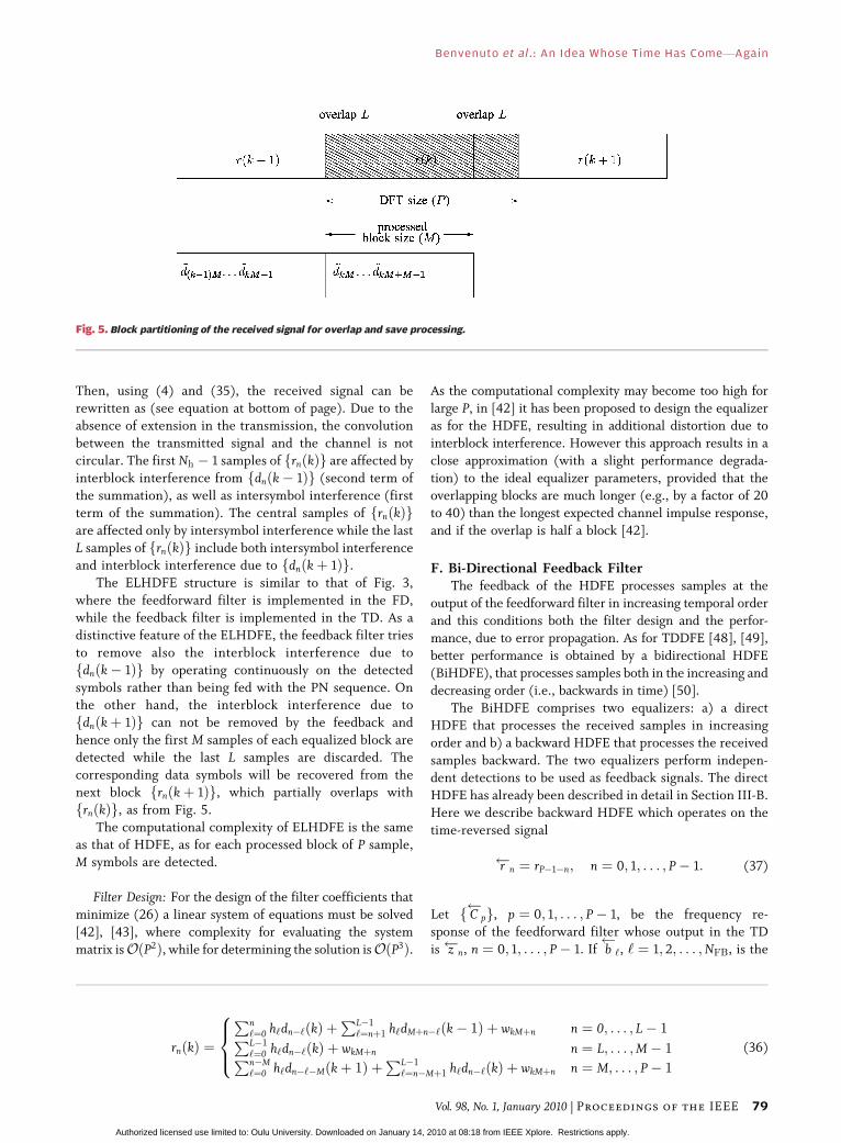
Then, using (4) and (35), the received signal can be
rewritten as (see equation at bottom of page). Due to theabsence of extension in the transmission, the convolution
between the transmitted signal and the channel is not
circular. The first Nh � 1 samples of frnðkÞg are affected by
interblock interference from fdnðk� 1Þg (second term of
the summation), as well as intersymbol interference (first
term of the summation). The central samples of frnðkÞgare affected only by intersymbol interference while the last
L samples of frnðkÞg include both intersymbol interferenceand interblock interference due to fdnðkþ 1Þg.
The ELHDFE structure is similar to that of Fig. 3,
where the feedforward filter is implemented in the FD,
while the feedback filter is implemented in the TD. As a
distinctive feature of the ELHDFE, the feedback filter tries
to remove also the interblock interference due to
fdnðk� 1Þg by operating continuously on the detected
symbols rather than being fed with the PN sequence. Onthe other hand, the interblock interference due to
fdnðkþ 1Þg can not be removed by the feedback and
hence only the first M samples of each equalized block are
detected while the last L samples are discarded. The
corresponding data symbols will be recovered from the
next block frnðkþ 1Þg, which partially overlaps with
frnðkÞg, as from Fig. 5.
The computational complexity of ELHDFE is the sameas that of HDFE, as for each processed block of P sample,
M symbols are detected.
Filter Design: For the design of the filter coefficients that
minimize (26) a linear system of equations must be solved
[42], [43], where complexity for evaluating the system
matrix isOðP2Þ, while for determining the solution isOðP3Þ.
As the computational complexity may become too high for
large P, in [42] it has been proposed to design the equalizeras for the HDFE, resulting in additional distortion due to
interblock interference. However this approach results in a
close approximation (with a slight performance degrada-
tion) to the ideal equalizer parameters, provided that the
overlapping blocks are much longer (e.g., by a factor of 20
to 40) than the longest expected channel impulse response,
and if the overlap is half a block [42].
F. Bi-Directional Feedback FilterThe feedback of the HDFE processes samples at the
output of the feedforward filter in increasing temporal order
and this conditions both the filter design and the perfor-
mance, due to error propagation. As for TDDFE [48], [49],
better performance is obtained by a bidirectional HDFE
(BiHDFE), that processes samples both in the increasing and
decreasing order (i.e., backwards in time) [50].
The BiHDFE comprises two equalizers: a) a directHDFE that processes the received samples in increasing
order and b) a backward HDFE that processes the received
samples backward. The two equalizers perform indepen-
dent detections to be used as feedback signals. The direct
HDFE has already been described in detail in Section III-B.
Here we describe backward HDFE which operates on the
time-reversed signal
r n ¼ rP�1�n; n ¼ 0; 1; . . . ; P� 1: (37)
Let f C
pg, p ¼ 0; 1; . . . ; P� 1, be the frequency re-
sponse of the feedforward filter whose output in the TD
is z n, n ¼ 0; 1; . . . ; P� 1. If b
‘, ‘ ¼ 1; 2; . . . ;NFB, is the
rnðkÞ ¼
Pn‘¼0 h‘dn�‘ðkÞ þ
PL�1‘¼nþ1 h‘dMþn�‘ðk� 1Þ þ wkMþn n ¼ 0; . . . ; L� 1PL�1
‘¼0 h‘dn�‘ðkÞ þ wkMþn n ¼ L; . . . ;M� 1Pn�M‘¼0 h‘dn�‘�Mðkþ 1Þ þ
PL�1‘¼n�Mþ1 h‘dn�‘ðkÞ þ wkMþn n ¼ M; . . . ; P� 1
8><>: (36)
Fig. 5. Block partitioning of the received signal for overlap and save processing.
Benvenuto et al.: An Idea Whose Time Has ComeVAgain
Vol. 98, No. 1, January 2010 | Proceedings of the IEEE 79
Authorized licensed use limited to: Oulu University. Downloaded on January 14, 2010 at 08:18 from IEEE Xplore. Restrictions apply.

impulse response of the feedback filter. Then, the signal at
the output of backward HDFE is
~d
n ¼ z n þXNFB
‘¼1
b
‘ d
n�‘; n ¼ 0; 1; . . . ;M� 1 (38)
where d
n is the detected signal based on ~d
n. Initially,
d
n ¼ pLþn, n ¼ �1;�2; . . . ;�L. The BiHDFE scheme is
shown in Fig. 6. The output of the backward HDFE f ~d
ngis time reversed to obtain f~dBAC;ng. Lastly, output signals
f~dDIR;ng and f~dBAC;ng, from the HDFEs, respectively, are
processed for soft detection.In order to simplify the soft detection, we consider
arbitration [51] which implements a local maximuma posteriori criterion. In particular, the quality of the
local match between the reconstructed signal using
detected data, and the received sequence is estimated
over a window of size W around the symbol of interest. The
symbol of the detected sequence that provides a closer
match with the received sequence, is selected in thearbitration. First, a hard decision is taken on f~dDIR;ng and
f~dBAC;ng and the PN sequence is added, to obtain fsDIR;ngand fsBAC;ng, respectively. Let also indicate the recon-
structed signals at the output of the channel as
rDIR;n ¼XNh�1
‘¼0
h‘ sDIR;n�‘ (39)
rBAC;n ¼XNh�1
‘¼0
h‘ sBAC;n�‘: (40)
Note that (39) and (40) can be implemented in the FD as
sDIR;n and sBAC;n satisfy conditions on circularity. Then the
distance of the reconstructed signals from the received
signal is evaluated as
�DIR;n ¼1
W
XW=2
‘¼�W=2þ1
jrnþ‘ � rDIR;nþ‘j2 (41)
�BAC;n ¼1
W
XW=2
‘¼�W=2þ1
jrnþ‘ � rBAC;nþ‘j2: (42)
Lastly, the decision rule is as follows:
dn ¼dDIR;n if �DIR;n � �BAC;n
dBAC;n if �DIR;n > �BAC;n.
�(43)
The computational complexity of the structure of
BiHDFE is ð3P=2MÞ log2ðPÞþ2NFB�ð2=3ÞPMþ2ðW=MÞ,roughly double that of HDFE.
Filter Design: It can be shown that, according to the
minimum MSE criterion [50]
b
‘ ¼ b�‘ ; ‘ ¼ 1; 2; . . . ;NFB (44)
while
C
p ¼ C�P�p p ¼ 0; 1; . . . ; P� 1: (45)
The resulting design complexity in terms of complex
multiplications is the same as that of HDFE.
G. Iterative Equalization MethodsThere are alternative design methods which, for simple
signal processing with no matrix inversion, yield an
approximate minimum MSE solution by using classicalleast mean square (LMS) or recursive least square (RLS)
algorithms [26]. Note that for an FD linear equalizer these
iterative algorithms are fairly straightforward to use on a
per-subcarrier basis, while for a HDFE it is not simple to
force the constraint that the TD feedback filter should be
causal, and we should resort to a HDFE-NP, with two error
signals, one to update the feedforward filter and one to
update the feedback filter [26]. One problem with theseiterative methods, is that, since the update is block-based,
their convergence is very slow. Besides, they need a
training sequence. Hence, they should be used only for
tracking the optimal solution in the presence of a slowly
time varying channel.
Recently, a new iterative equalization method has been
proposed [52], [53], denoted iterative block DFE (IBDFE),
Fig. 6. The BiHDFE structure.
Benvenuto et al.: An Idea Whose Time Has ComeVAgain
80 Proceedings of the IEEE | Vol. 98, No. 1, January 2010
Authorized licensed use limited to: Oulu University. Downloaded on January 14, 2010 at 08:18 from IEEE Xplore. Restrictions apply.
with the feedback working in the FD, where within eachblock, detection and design are updated in sequence. This
configuration yields best performance when it interacts with
decoding. Equations for IBDFE are given in Section IV-C for
a MIMO system (including the single antenna system as a
special case) while adaptive versions of the HDFE with noise
prediction are given in Section V-C.
IV. EXTENSIONS TO MIMO SYSTEMSAND PERFORMANCE COMPARISON
While MIMO techniques have been widely proposed andshow great promise for application in future wireless
systems, the number of MIMO implementations has up to
now been modest, mainly due to their hardware complex-
ity. In this context FD filtering in MIMO systems is an
approach to drastically simplify both filter design and
operation, as will be seen in the next subsections. How-
ever, to the general reader, who may find these parts very
technical, we suggest to go directly to Section IV-E onturbo equalization or even Section IV-F on performance
comparison for single-input single-output systems.
It is known that we can increase substantially the
capacity of a given system by employing multiple antennas
at both the transmitter and the receiver [54]. This allows
highly spectrally-efficient spatial multiplexing techniques
where the data signal is split into NT parallel streams, each
one associated to a different transmit antenna. Byemploying NR � NT antennas at the receiver it is possible
to separate the NT data streams, at least in theory. As an
example, we have Bell Laboratories layered space-time
(BLAST) coding architectures [55]–[57]. This concept can
also be extended to space-division multiple access
techniques where we employ multiple antennas at the
base station to increase the number of simultaneous users
in a given cell, allowing a significant increase in the systemspectral efficiency, while reducing the transmit power
requirements for the mobile terminals [58], [59].
At the receiver, we need to separate the streams.1 The
performance can be improved by employing interantenna
interference cancellation schemes. For flat fading MIMO
channels the antenna separation is relatively simple, since
we can just invert the channel matrix. However, for
frequency-selective channels the receiver can be muchmore complex.2 In fact, we need to jointly separate the
streams associated to different transmit antennas and to
equalize the channel. A way of achieving this is by employing
MIMO TD equalizers as proposed in [60]–[62]. However, as
with other TD receivers, their complexity can be very high
for severely time-dispersive channels and FD implementa-
tions are strongly recommended. The frequency domain
equalization designs described in the previous section can beextended for MIMO scenarios. Several hybrid DFE schemes
were proposed for MIMO systems [63]–[65].
In fact, for MIMO receivers we can consider two
alternative detection schemes [62]:
• MIMO-DFE or detection with parallel interference
cancellation (PIC). In this case, detection consists
of NT parallel detection stages, where symbols of
all streams at a given instant are detectedsimultaneously by linear processing of the received
signal and partial cancellation of interference from
the other streams and residual intersymbol inter-
ference using previously detected data.
• Layered space-time DFE (LST-DFE) or detection
with successive interference cancellation (SIC)
where we detect one stream at a time and cancel
interference from already detected streams, as wellas the residual intersymbol interference for the
stream that is being detected. It is desirable to rank
the streams according to some quality measure
(ideally it should be the bit error rate (BER) or
mean square error for each stream after the corres-
ponding detection stage; to simplify the receiver,
the average power associated to each stream could
also be employed) and to detect the streams fromthe best to the worst.
These receivers are closely related to SIC and PIC receivers
for CDMA [66]. Although the PIC structure is in general
more complex, it allows a parallel design, which can be
advantageous from the implementation point of view. More-
over, the detection delay for PIC structures is much lower
than for the SIC structure and it is not necessary to rank the
streams. Surprisingly, typical performance is worse for PICapproaches, since detection of worse streams is affected by
high interference of the best streams [62], [67].
The approach taken here is similar to that of [68] and
[69], which considered TD processing.
The received FD signal at frequency p corresponding to
(12) with the block index k dropped, is now a NR-size
column vector Rp ¼ ½Rð1Þp ; Rð2Þp ; . . . ; RðNRÞp �T , given by
Rp ¼XNT
i¼1
HðiÞp SðiÞp þWp; p ¼ 0; 1; . . . ; P� 1 (46)
where HðiÞp ¼ ½Hð1;iÞp ;Hð2;iÞp ; . . . ;HðNR;iÞp �T is the NR-size
column vector representing the channel frequency response
from transmitter i ¼ 1; 2; . . . ;NT, SðiÞp represents the FD
signal from transmitter i and Wp ¼ ½Wð1Þp ;Wð2Þp ; . . . ;WðNRÞp �T
is the FD white noise vector with E½WpWHp � ¼ �2
W INR.
A. The MIMO-HDFEThe HDFE designs described in Section III can be
extended for MIMO scenarios [63], [64]. The MIMO-HDFE
1The streams can be associated with different antennas of the samemobile terminal (as in BLAST systems) or with different mobile terminals(as in space-division multiple access systems).
2For systems with FD processing the receiver complexity can be keptlow since the channel can be modeled as parallel flat fading channels.
Benvenuto et al.: An Idea Whose Time Has ComeVAgain
Vol. 98, No. 1, January 2010 | Proceedings of the IEEE 81
Authorized licensed use limited to: Oulu University. Downloaded on January 14, 2010 at 08:18 from IEEE Xplore. Restrictions apply.

consists of a FD feedforward filter and a TD feedback filterwith a temporal span of NFB taps. The structure is fully
connected, where cross-feedbacks are implemented, to feed
back all the past decisions from all streams into the detection
of each stream. In the MIMO-HDFE all NT stream symbols
at a given instant are detected simultaneously and on
detecting stream i (i ¼ 1; 2; . . . ;NT, we use a feedforward
filter with FD coefficients collected into the row vector
fCðiÞp ¼ ½Cði;1Þp ; Cði;2Þp ; . . . ; Cði;NRÞp �g, and feedback filters with
TD coefficients collected into the row vector
fbðiÞ‘ ¼ ½bði;1Þ‘ ; . . . ; b
ði;NTÞ‘ �g, ‘ ¼ 1; 2; . . . ;NFB.
The output in FD of the ith stream is ZðiÞp ¼ CðiÞp Rp. The
corresponding TD signal zðiÞn is obtained by IDFT of fZðiÞp g.At detection point, the signal can be written as
~dðiÞn ¼ zðiÞn þ
XNFB
‘¼1
bðiÞ‘ sn�‘ (47)
where sn ¼ ½sð1Þn ; sð2Þn ; . . . ; sðNTÞn �T is the NT-size column
vector with all streams symbols detected at instant n and
extended as in (22).
The minimum MSE feedforward coefficient vector is
[see also (30)]
CðiÞp ¼ ~EðiÞ�p HH
p
XNT
m¼1
HðmÞp HðmÞHp þ �W
�2D
2INR
" #�1
(48)
where
Hp ¼ Hð1Þp ;Hð2Þp ; . . . ;HðNTÞp
h i(49)
and ~EðiÞp ¼ ei � BðiÞp , with fBðiÞp g, p ¼ 0; 1; . . . ; P� 1 the
row vector DFT of fbðiÞ‘ g, ‘ ¼ 1; 2; . . . ;NFB, and ei ¼½0; . . . ; 0; 1; 0; . . . ; 0� denoting the ith unit row vector.
Let us define
Qp ¼ �2W INT
þ �2DHH
p Hp
h i�1
(50)
and fvðiÞn g, as the DFT of fQpg, p ¼ 0; 1; . . . ; P� 1. Let us
also define
vðiÞ ¼ vðiÞ1 ; v
ðiÞ2 ; . . . ; v
ðiÞNFB
h iT
ei (51)
AðiÞ ¼
vðiÞ0 v
ðiÞ�1 v
ðiÞ1�NFB
vðiÞ1 v
ðiÞ0 v
ðiÞ2�NFB
vðiÞ2 v
ðiÞ1 v
ðiÞ3�NFB
vðiÞNFB�1 v
ðiÞ0
266666664
377777775: (52)
The optimum vector of feedback coefficients bðiÞ ¼½bðiÞ1 ; b
ðiÞ2 ; . . . ; b
ðiÞNFB�T is the solution of the system of
equations AðiÞbðiÞ ¼ vðiÞ. Note the high complexity of theproposed solution.
B. The LST-HDFEThe LST-HDFE for detecting NT streams of data
symbols has NT successive multiple-input-single-output
HDFEs. At each stage, the best stream data block (see
comments on SIC), is selected, detected by a multiple-
input-single-output HDFE, transformed to FD, subtracted
from the received signal in the FD and the residual signal is
passed to the next step for equalization and detection ofthe next best data block.
For the sake of simplicity, we will assume that the
streams are ordered according to some criterion, with
i ¼ 1 corresponding to the best stream and i ¼ NT the
worse. We will also assume that we are detecting the ithstream (i.e., stage i) and the previous ði� 1Þ streams were
already detected and removed from the FD output signal
fRpg to obtain fRðiÞp g. Given fRðiÞp g, we apply the scalar
HDFE of Section III to yield fdðiÞn g, n ¼ 0; 1; . . . ;M� 1.
Note that for the LST-HDFE at stage i, the input of the
feedback filter consists only of the previous detected data
on the ith stream itself. In fact, each stage of LST-HDFE
(from before cancellation of previous detected streams to
detected data fdðiÞn g) is a multiple-input-single-output
HDFE, i.e., a MIMO-HDFE with NT � iþ 1 inputs andone output. The number of interfering signals is reduced
by one at each stage due to the cancellation of previous
detected streams in the front end.
C. Iterative Block DFE (IBDFE)In the IBDFE, both the feedforward and the feedback
filters are implemented in the FD [52], [53]. The equalizer
includes two parts: 1) the feedforward filter, which
partially equalizes for the interference and 2) the feedback
signal, which removes part of the residual interference. In
the IBDFE, the design of the various filter/signals and datadetection is iterated NI times.
Also in this case, as for HDFE, error propagation due to
the feedback is limited to within one block. Moreover,
feedforward and feedback operations are both realized in
the FD, while both TDDFE and HDFE include a feedback
operating in the TD. On the other hand, since detection is
performed on a per-block basis, the effectiveness of the
feedback to cancel interference is limited by the reliabilityof the detected data at the previous iteration. Indeed, the
iterative process gradually increases the reliability of the
detected data. However, if the initial detected data is
exceedingly poor, the iterative process may not be able to
effectively cancel the interference. An integration of
IBDFE with CDMA transmission has been proposed in
[70], where chip interleaving and multiuser interference
Benvenuto et al.: An Idea Whose Time Has ComeVAgain
82 Proceedings of the IEEE | Vol. 98, No. 1, January 2010
Authorized licensed use limited to: Oulu University. Downloaded on January 14, 2010 at 08:18 from IEEE Xplore. Restrictions apply.

cancellation has been considered to improve detection.Indeed, for CDMA, the use of chip interleaving provides a
significant robustness against error propagation, even with-
out the use of coding.
The following development is similar to that in [71],
[72] and to the soft decision feedback development of [52],
but is generalized to multiuser MIMO.
In a PIC approach, at each iteration q we have the DFT
component of the soft symbols fed back from the detectorfor each stream i in the FD, denoted as m
Sði;q�1Þp
, i ¼ 1;2; . . . ;NT. For the detection of stream i, we first remove
best estimate of interference to Rp from other streams and
then perform equalization. In IBDFE equalization is
performed both by the FD feedforward 1� NR row vector
filter Cði;qÞp and by the removal of the residual intersymbol
interference through the feedback signal Yði;qÞp whose
expression is determined in the following. Hence, thespace-frequency equalizer output at frequency p for stream
i at the qth iteration, is
~Sði;qÞp ¼ Cði;qÞp Rp �
XNT
m¼1;m6¼i
HðmÞp mSðm;q�1Þp
" #þ Yði;qÞp : (53)
At the first iteration ðq ¼ 1Þ, the feedback terms are zero,
and the equalizer is a linear minimum MSE equalizer. The
case where NT ¼ 1 and NR > 1 corresponds to a scenario
with receive diversity. In this case, the receiver design isstill validVnaturally, we do not need to remove the
interference between antennas in (53) and the receiver
coefficients are still given by (59). As shown in [73], a
similar approach could be employed for systems employing
Alamouti-like transmit diversity [74]. Note that for SIC we
detect streams successively for each iteration and we use
mSðm;qÞp
whenever it is available, i.e., for streams that were
already detected at each iteration.
After equalization (53), the IDFT of f~Sði;qÞp g, p ¼ 0;
1; . . . ; P� 1, follows to obtain ~dði;qÞn , n ¼ 0; 1; . . . ;M� 1,
on which soft detection is performed. In particular, ~dði;qÞn is
described as the sum of the desired data signal and a
disturbance term that collects the effects of both noise and
residual interference, modeled as a complex Gaussian ran-
dom variable with zero mean and variance �ði;qÞ2SD . Hence
the a posteriori probability of detecting dði;qÞn ¼ �, where �
belongs to the constellation alphabet A, is
fdði;qÞn
ð�Þ ¼ K0e�~dði;qÞn ��ði;qÞ��� ��2=�ði;qÞ2
SD ;
� 2 A; n ¼ 0; 1; . . . ;M� 1 (54)
with �ði;qÞ the gain of the desired signal and K0 a
normalization factor. The soft detected symbol in TD is
the mean of dði;qÞn , for n ¼ 0; 1; . . . M� 1,
mdði;qÞn
¼ E dði;qÞn
h i¼X�2A
�fdði;qÞn
ð�Þ: (55)
In (53) the soft detected signal in the FD, fmSði;qÞn
g, to be
used for the cancellation of other streams is the P-size DFT
of fmdði;qÞn
g, extended with the PN sequence [see (11)].
Filter and Signal Design: Again, the feedforward filters
Cði;qÞp and the feedback signals fYði;qÞp g are designed to
minimize the MSE (26), where the expectation is taken
with respect to fsði;qÞn g and fwði;qÞn g, given the observation
~dði;q�1Þn . In order to compute (26) we assume that the
conditional (i.e., given ~dði;q�1Þn ), statistics of fdði;qÞn g are
those of dði;q�1Þn .
Assuming that fdði;qÞn g are statistically independent the
variance of Sði;qÞp is given by
�Sði;qÞp
¼E Sði;qÞp � m
Sði;qÞp
��������
2" #
¼XM�1
n¼0
X�2Aj�j2f
dðqÞn
ð�Þ � mdði;qÞn
��� ���2: (56)
Note that (56) is independent of p.
After inserting (53) into (26) and using (56), the MSE
for the ith stream at the qth iteration is
Jði;qÞSD ¼
1
P2
XP�1
p¼0
n�2
W Cði;qÞp Cði;qÞHp þ Cði;qÞp :
�XNT
m¼1
&ðm;q�1Þp HðmÞp HðmÞHp Cði;qÞHp
þ mSði;q�1Þp
þ�Sði;qÞp
� �
� Cði;qÞp HðiÞp HðiÞHp Cði;qÞHp � 1� �þ Yði;qÞp
��� ���2þ 2Re
hYði;qÞ�p m
Sði;q�1Þp
Cði;qÞp HðiÞp � 1� �io
(57)
Minimizing (57) with respect to Yði;qÞp and Cði;qÞp , we get
Yði;qÞp ¼ mSði;q�1Þp
1� Cði;qÞp HðiÞp
h i(58)
Benvenuto et al.: An Idea Whose Time Has ComeVAgain
Vol. 98, No. 1, January 2010 | Proceedings of the IEEE 83
Authorized licensed use limited to: Oulu University. Downloaded on January 14, 2010 at 08:18 from IEEE Xplore. Restrictions apply.

and
Cði;qÞp ¼HðiÞHp
XNT
m¼1
HðmÞp HðmÞHp þ �2W
�Sðm;q�1Þp
INR
24
35�1
: (59)
A slight enhancement of performance is obtained by
adding the constraint of a unitary gain of the useful signal,
i.e., �ði;qÞ ¼ Cði;qÞp HðiÞp ¼ 1. In this case Cði;qÞp turns out to bea scaled version of (59).
About complexity, at each iteration a IDFT and a per-
subcarrier multiplication is performed, so that for a single
input-single output system the structure complexity is
ðNIP log2ðPÞ=MÞ � ðP=MÞ þ ðP=MÞ complex multiplica-
tions, where we accounted for the (I)DFTs and we added a
P=M term to account for the various real multiplications
required for the computation of the soft signals. For thedesign, we only account for 3P complex multiplications in the
computation of channel dependent terms in (58) and (59).
D. Comparison of MIMO ReceiversThe comparison between MIMO-HDFE and LST-
HDFE can be found in [64], [75]. [75] also includes
comparisons with MIMO OFDM schemes. For an uncoded
or a high code rate system, when the channel has large
intersymbol interference components MIMO-HDFE and
LST-HDFE performance is similar. For low code rates,
LST-HDFE outperforms MIMO-HDFE. At low signal-to-
noise ratio (SNR), LST-HDFE receivers suffer more fromerror propagation; at high SNR the error propagation is
limited and LST-HDFE receivers enjoy significant perfor-
mance improvement over the MIMO-HDFE. In general
SCM yields better performance than OFDM, with a larger
advantage for high code rates.
IBDFE schemes were studied in [76]–[78]. The perfor-
mance with these schemes is excellent and can be very close
to the matched filter bound, especially for severely time-dispersive channels with rich multipath propagation.
E. Turbo Equalization, or IBDFE With CodingWhen IBDFE is integrated with coding/decoding, it
comes also under the name of turbo equalization in the
FD [71]. In this case, the data bits must be encoded, inter-
leaved and mapped into symbols before transmission. At
the receiver, the feedback part of the turbo equalization in
the FD includes deinterleaving, decoding and soft re-
encoding, as shown in Fig. 7. The equalized samples are
first demapped by a soft demapper that provides the loglikelihood ratio for each coded bit. A deinterleaver and soft
output decoder follow. The latter provides the refined log
likelihood ratio by exploiting the properties of the error
correcting code, [71], [72], [79]. Interleaving follows
together with soft mapping that provides probabilities
fdðqÞn
ð�Þ, � 2 A. The remaining blocks of Fig. 7 show
operations for filter design as for IBDFE.
For quaternary phase shift keying (QPSK) symbols withA ¼ f1 jg, soft demapping and mapping simplify as
follows. Defining the complex log likelihood ratio as
�ði;qÞn ¼ �ði;qÞR;n þ j�ði;qÞI;n , where �
ði;qÞR;n ð�
ði;qÞI;n Þ is associated to
Re½dði;qÞn � ðIm½dði;qÞn �Þ, the soft demapper yields [26]
�ði;qÞn ¼4m
dði;q�1Þn
�ði;qÞ2SD
(60)
i.e., the log likelihood ratio is proportional to the equalizer
soft output. In turn, if ði;qÞn ¼ ði;qÞR;n þ jði;qÞI;n is the complex
log likelihood ratio at the decoder output (extrinsic
information) we have
mdði;q�1Þn
¼ tanhði;qÞR;n
2
!þ j tanh
ði;qÞI;n
2
!: (61)
Fig. 7. Feedback part of turbo equalization (IBDFE with coding).
Benvenuto et al.: An Idea Whose Time Has ComeVAgain
84 Proceedings of the IEEE | Vol. 98, No. 1, January 2010
Authorized licensed use limited to: Oulu University. Downloaded on January 14, 2010 at 08:18 from IEEE Xplore. Restrictions apply.

F. ComparisonWe compare the nonlinear FD equalization schemes in
two respects: performance and complexity. We consider a
single antenna scenario ðNR ¼ NT ¼ 1Þ.
Performance Comparison: In order to compare the
performance of the systems, we considered a QPSK trans-
mission on a Rayleigh fading channel having an exponen-
tial power delay profile with aroot-mean square delayspread �rms=T ¼ 2, normalized with respect to the symbol
period. The channel estimate is assumed ideal. The size of
the DFT has been set to P ¼ 128, while the PN extension
length is L ¼ 16. For TDDFE, NFF ¼ 16 and NFB ¼ 16.
Fig. 8 [52] shows the average BER as a function of the
channel average SNR for the following schemes: a) TDDFE
with possible errors in the feedback process, b) TDDFE
with ideal (ID) feedback signal (labelled TDDFE-ID),c) matched filter bound, d) HDFE and e) IBDFE with
various iterations. From Fig. 8 we note that IBDFE after
four iterations provides the lowest BER outperforming
even TDDFE-ID. HDFE has a performance close to that of
TDDFE and clearly all nonlinear structures outperform the
FD linear equalizer provided by the IBDFE at the first
iteration. In this scenario the advantage of IBDFE over
TDDFE is about 1 dB. We note that IBDFE is 2 dB awayfrom the matched filter bound for this channel.
As for ELHDFE, a fair comparison with the other
schemes should include the different data rate due to the
absence of prefixes or sequences. To this end, we evaluated
the throughput when a stop and wait automatic repeat
request (ARQ) strategy is used to retransmit the packets in
error. We assume a full-buffer condition and we neglect
the overhead time for the acknowledging [43]. Fig. 9shows the achievable throughput as a function of the
average SNR for HDFE and ELHDFE. The reference
scenario is a transmission of a signal. We assume a DFT
size of P ¼ 64 symbols, �rms=T ¼ 2 and L ¼ 16. A rate 1/2
convolutional code having generating polynomials (133_8,171_8) is used at the transmitter. We note that in this
scenario the performance loss due to the increased inter-
ference for ELHDFE is widely compensated by the
increased throughput due to the absence of extension,
yielding 30% more throughput than that of HDFE.
Computational Complexity: Although in some cases BER
improvement might not be enough to justify the adoptionof FD structures, it is important to compare the
computational complexity of the various structures to
understand the benefits of the FD approach. As a reference
scenario we consider P ¼ 256, L ¼ NFF ¼ NFB ¼ 16.
Table 1 summarizes the complexity for the equalizer
structures. It shows that HDFE, ELHDFE and IBDFE
significantly reduce the complexity by about 25% with
respect to TDDFE. Table 2 shows instead the complexityrelated to the equalizer design. We observe that the
complexity of the HDFE and of the bidirectional HDFE
design grows quadratically with the number of feedback
filter taps, while the complexity of TDDFE grows as the
third power of the filter taps. ELHDFE has a considerably
higher design complexity, as it grows with P3, since the
circularity of convolution between the transmitt signal and
the channel cannot be exploited. As mentioned, asuboptimal solution could be to design the same filter as
for HDFE, with considerably lower complexity but also an
increased intersymbol interference [42].
V. CHANNEL ESTIMATION METHODS
In order to perform channel estimation in the FD, known
blocks of training symbols, or pilot symbols, are transmittedFig. 8. BER performance of various equalizer structures
(from [52]). MF: matched filter bound.
Fig. 9. Throughput performance comparison of HDFE and
ELHDFE (from [43]).
Benvenuto et al.: An Idea Whose Time Has ComeVAgain
Vol. 98, No. 1, January 2010 | Proceedings of the IEEE 85
Authorized licensed use limited to: Oulu University. Downloaded on January 14, 2010 at 08:18 from IEEE Xplore. Restrictions apply.

in addition to data, as a reference for the equalizer adap-tation process at the start of transmission, and periodically
thereafter to ensure accurate adaptation to time-varying
channels. Once equalizer parameters are initially estimat-
ed with sufficient accuracy, receiver hard or soft decisions
can be used for further improving tracking accuracy and
performance, in an iterative fashion.
A. Types of Training SignalsThe traditional method of transmitting pilot symbols in
SCM is by time multiplexing them with data; training
blocks of known pseudo random data symbols (also some-
times called unique words) are interspersed at regular
intervals among longer blocks of data symbols. The pilot
blocks should be at least twice as long as the expected
maximum channel impulse response length. The pilot
block should preferably be designed to have a constantenvelope and almost flat spectrum. Constant amplitude
zero autocorrelation (CAZAC), maximal length PN se-
quences, or Chu sequences [80], have this property. It is
pointed out in [29] and in Section II-A that a periodic pilot
block (e.g., a PN extension) can replace the cyclic prefix at
the beginning of every data block, and then the receiver’s
DFT processing block consists of the data block plus the
pilot block.Fig. 10 shows the arrangement of a time multiplexed
pilot block followed by a data block, and how it can be
processed in the FD. Suppose the pilot block length is NP
time samples. Taking the DFT of the received pilot block,
and dividing by the DFT of the transmitted pilot block
gives NP uniformly-spaced estimated samples of the chan-
nel frequency response [see (62) below]. What is needed
for the equalizer design is P > NP uniformly spacedsamples of the response. So FD interpolation is necessary.
In a multiple access scenario, a single time multiplexed
pilot block may contain pilots from more than one user
signal. An efficient way to do this is to generate each user’s
pilot signal as a IFDMA waveform, orthogonal with thoseof the other users, as described in Section II-B. All such
pilot waveforms may be superimposed to form the pilot
block.
The channel impulse response or the equalizer response
could be estimated and adapted from one or more suc-
cessive time multiplexed pilot blocks by using well known
LMS or RLS TD system identification methods [81]. How-
ever for impulse responses spanning many symbol inter-vals, such TD processing, with adaptive transversal filters,
would largely nullify the signal processing complexity
reduction advantages of FD equalization. Thus, FD pro-
cessing is preferable for channel estimation and equalizer
adaptation.
Pilots can also be frequency multiplexed with data. In
this case, pilot tones displace or replace data-carrying tones
in the FD. Displacement of data tones by uniformly-spacedpilot tones is commonly used for OFDM systems. The total
bandwidth is then increased by the number of pilot-
occupied tones, or for fixed bandwidth the data payload is
reduced by the inserted pilots. Frequency multiplexed
pilots can also be used in the generalized multicarrier
context with DFT-precoded OFDM [37], [82]. In the latter
case, the resulting data-carrying signal is generally not a
pure SCM signal, as pointed out in Section II-B but it hasthe low peak to average power ratio properties of SCM
signals and its receiver structure is similar to that of pure
SCM signals.
Loss of spectral efficiency due to pilot insertion can be
avoided if data tones are replaced by regularly-spaced pilots.
This type of frequency multiplexed pilot insertion, called
FD superimposed pilot technique, has the effect of causing
periodic nulls to appear in the spectrum of the transmittedsignal (at the frequencies of the inserted pilots). Powerful
nonlinear equalization techniques such as IBDFE or turbo
equalization can mitigate the resulting received signal dis-
tortion, so that FD superimposed pilot technique systems
Fig. 10. Time multiplexed (TM) pilots, showing FD processing at the receiver (cyclic prefixes are not shown). The dash-dot contour
is the interpolated channel frequency response.
Benvenuto et al.: An Idea Whose Time Has ComeVAgain
86 Proceedings of the IEEE | Vol. 98, No. 1, January 2010
Authorized licensed use limited to: Oulu University. Downloaded on January 14, 2010 at 08:18 from IEEE Xplore. Restrictions apply.

can approach to within about 1 dB the performance of pilot
tone displacement systems, while requiring no extra
bandwidth or overhead for pilots [37], [83].
Fig. 11 illustrates how pilots frequency multiplexedwith data are processed at a receiver. The NP received
subcarriers bearing pilot tones are selected, and after
division by the transmitted pilot tones, the NP samples of
the channel impulse response estimate are interpolated to
P samples. Channel estimation processing in the FD is
identical for time and frequency multiplexed pilots, after
the expansion or selection of the pilot frequencies.
Time multiplexed pilots have the advantage that theyare temporally separate from the data blocks, and therefore
they do not affect the peak to average power ratio prop-
erties of the transmitted signals. They can also be used for
purposes of timing synchronization. However, as men-
tioned below, they require their own cyclic prefix of suf-
ficient length to avoid interblock interference, thus adding
to the pilot overhead. Frequency multiplexed pilots share
the cyclic prefix with data, avoiding the extra overhead(and in the case of FD superimposed pilot technique pilots,
consume no overhead). Frequency multiplexed pilots can
also be advantageous from a system implementation per-
spective, if OFDM and SCM transmission modes coexist in
the same system. On the other hand, SCM blocks that
contain frequency multiplexed pilots have higher peak to
average power ratio than nonpilot blocks, and so these
blocks require slightly higher power backoff.The temporal spacing of pilot blocks depends on the
maximum expected Doppler frequency of the channel.
Sampling theory considerations suggest that the frequency
at which pilot blocks are transmitted should be about twice
the highest expected Doppler frequency and the spacing of
pilots in frequency should be about half of the maximum
channel coherence bandwidth (equivalent to training
block lengths of about twice the maximum impulse re-sponse length) [84].
Equalizer parameters must be adapted, or trained, by
one or a combination of the following two methods:
1) Channel estimate-based adaptation, in which the
frequency or impulse responses of the channel or
channels are estimated, along with the signal to
noise ratio, and the results are substituted in the
appropriate formula for the equalizer response ofSection III.
2) Equalizer error-based adaptation, in which equal-
izer parameters are adapted directly, by feeding
back the equalizer’s output error to an adaptation
algorithm, such as LMS or RLS [81].
B. Channel Estimate-Based Adaptation: Pilot-BasedChannel Estimation
For indirect adaptation from pilot training, the channel
frequency response at a set of equally-spaced pilot fre-
quencies p0 2 P, during the training block is estimated as
Hp0 ¼Rp0
Tp0; p0 2 P (62)
where Rp0 is the P-size DFT of the channel output due to
the pilot at frequency p0. Tp0 is the pilot at that frequency in
the case of frequency multiplexed pilots. In the case of
time multiplexed pilots, Tp0 is the p0 component of the DFT
of the pilot training sequence. This approach to pilot-aided
channel estimation is equally applicable to OFDM and to
SCM. Most of the expressions for FD equalizer parametersin the previous section also require an estimate of the
additive white noise variance. This may be estimated in
several ways, for example by measuring the received power
spectrum at several out of band frequencies.
The number of pilot symbols NP is usually a small
fraction of the DFT size P, to keep pilot overhead low.
Interpolation in the FD is necessary to generate the esti-
mated channel frequency response at all P frequenciesneeded by the equalizer. A simple FD interpolation tech-
nique is to transform Hp0 to the TD by a NP-point inverse
DFT, pad it with P� NP zeros, and transform back to the FD
with a P-point DFT [85] to get Hp for p ¼ 0; 1; . . . ; P� 1. A
more accurate interpolation is to use a Wiener interpolation
filter designed according to the channel’s FD correlation
properties if these are known or assumed, windowing over a
set of adjacent frequencies [84], [86]. A joint or separateinterpolation in the TD is necessary to extend channel
estimates to data blocks that are not associated with pilot
blocks [84], [87], [88]. The extension to multiple transmit-
ting and receiving antennas is straightforward [88]. A
distinct set of pilots must be transmitted from each stream,
separated in time, frequency or code from those of other
users [39], [89]. Thus data-displacing pilot overhead
Fig. 11. Frequency multiplexed pilots, showing FD processing
at the receiver (cyclic prefixss are not shown). The dash-dot contour is
the interpolated channel frequency response.
Benvenuto et al.: An Idea Whose Time Has ComeVAgain
Vol. 98, No. 1, January 2010 | Proceedings of the IEEE 87
Authorized licensed use limited to: Oulu University. Downloaded on January 14, 2010 at 08:18 from IEEE Xplore. Restrictions apply.
increases in proportion to the number of simultaneoustransmitted signals. Equation (62) has a counterpart for
estimating the vector channel of the ith stream from its pilots
TðiÞp0 as
HðiÞp0 ¼
Rp0
TðiÞp0
; p0 2 P: (63)
Note that the use of (62) or (63) to estimate the chan-
nel for FD equalization assumes that each pilot training
sequence has its own cyclic prefix appended to it.
Otherwise, Rp0 will be corrupted by an adjacent data
block. This prefix requirement is automatically satisfied in
the case of frequency multiplexed pilots, which share the
cyclic prefix with the data blocks in which they areembedded. However the addition of a cyclic prefix to a
time multiplexed pilot block substantially increases its
effective length, and hence the total pilot overhead. For
the case where U users’ pilots are frequency multiplexed,
via IFDMA, in a common pilot block, the added overhead
per user is reduced by a factor of U. In the absence of a
time multiplexed pilot cyclic prefix, the resulting random
data-induced error in the channel response estimate mustbe reduced by averaging over many successive training
blocks. Reference [90] proposes this approach for OFDM
with pseudorandom training blocks between successive
OFDM blocks.
C. Equalizer Error-Based AdaptationThe RLS algorithm can be used to design an HDFE. We
define the errors in the TD at block k as
enðkÞ ¼ dnðkÞ � ~dnðkÞ; n ¼ 0; 1; . . . ;M� 1: (64)
Now, an RLS with respect to filter coefficients at iteration
k, fCpðkÞg and fb‘ðkÞg, yields operations with large
matrices. An alternative is to operate in the FD also forthe feedback coefficients fBpðkÞg, p ¼ 0; 1; . . . ; P� 1.
However, now the problem is how to force the causality
constraint b0ðkÞ ¼ 0. Fortunately, the HDFE-NP structure
can be a valid alternative, when the global optimization of
RLS is split into two local optimizations [26].
In fact, we define two cost functions, one that
minimizes the error at the output of the feedforward and
the other the error at the detection point. For afeedforward at iteration k, fCpðkÞg, p ¼ 0; 1; . . . ; P� 1 at
the detection point, we introduce the FD error sequences
at equalizer output
EF;pðkÞ ¼ SpðkÞ � ZpðkÞ¼ SpðkÞ � CpRpðkÞ; p¼0; 1; . . . ; P�1 (65)
and the RLS algorithm [26] can be used to determine a(iterative) solution for fCpðkÞg, p ¼ 0; 1; . . . ; P� 1, in
terms of fCpðk� 1Þg, p ¼ 0; 1; . . . ; P� 1, and other quan-
tities. Indeed, the solution is on a per subcarrier basis
and the RLS is scalar. From the FD error sequence at the
equalizer output fEF;pðkÞg, p ¼ 0; 1; . . . ; P� 1, we deter-
mine by IDFT the (block k) error sequence feF;nðkÞ ¼dnðkÞ � znðkÞg, n ¼ 0; 1; . . . ;M� 1, which will be used to
update the feedback coefficients. For a feedback filter atiteration k, fb‘ðkÞg, ‘ ¼ 1; 2; . . . ;NFB, we define the TD
error at detection point eB;nðkÞ ¼ dnðkÞ � ~dnðkÞ. As from
(31) and (32) the input signal of the feedback filter has a
component proportional to zn. Hence it is
eB;nðkÞ ¼ eF;nðkÞ �XNFB
‘¼1
b‘ðkÞeF;n�‘ðkÞ (66)
and the classical vector RLS algorithm can be used to yieldan iterative solution for fb‘ðkÞg, ‘ ¼ 1; 2; . . . ;NFB.
In this derivation, a simpler algorithm as LMS could be
used instead of the RLS at a cost of a longer convergence.
Moreover, we note that the first optimization is simply the
design of an FD linear equalizer.
D. Iterative Channel EstimationNon-perfect channel estimation degrades equalization
and bit error rate performance. It is well known that pilot-
based channel estimation can be augmented by iterative
channel estimation using fed-back hard or soft decisions
from the receiver’s detector or decoder. Combining initialchannel estimation from pilots with subsequent iterative
channel estimation can yield bit error rate performance
within about 1 dB of that achievable with perfect channel
state information for OFDM [91], [92].
Similar iterative channel estimation improvements are
available for SCM and DFT-precoded OFDM systems [37],
[93]. Again, our approach is similar to that of [68], [69],
but in the FD, instead of the TD. In its simplest form, withthe use of hard receiver decisions at the qth equalizer
iteration ðq > 1Þ in a block, whose DFT is fSðqÞp g,p ¼ 0; 1; . . . P� 1, a channel estimate is
HðqÞp ¼
Rp
SðqÞp
; p ¼ 0; 1; . . . ; P� 1: (67)
The effect of any hard decision errors is spread over all
frequencies due to the DFT operation in forming SðqÞp .
There is a potential problem with noise enhancement
at frequencies where SðqÞp has a small magnitude; this
latter problem is not encountered in OFDM counterpart
systems, in which SðqÞp is a data symbol. The noise
Benvenuto et al.: An Idea Whose Time Has ComeVAgain
88 Proceedings of the IEEE | Vol. 98, No. 1, January 2010
Authorized licensed use limited to: Oulu University. Downloaded on January 14, 2010 at 08:18 from IEEE Xplore. Restrictions apply.

enhancement problem can be alleviated by modifying(67) as follows [37], [93]:
HðqÞp ¼
Rp
SðqÞp
SðqÞp
��� ��� > �T
Hð0Þp S
ðqÞp
��� ��� � �T
8><>: (68)
where Hð0Þp is the initial channel estimate obtained from
the pilots, and �T is an empirically determined threshold.
For MIMO systems, the corresponding vector channel
estimate for the ith ði ¼ 1; 2; . . . ;NTÞ antenna at the qth
iteration is [94]
Hði;qÞp ¼
Rp�PNT
m¼1; 6¼iHðm;q�1Þp S
ðm;q�1Þp
Sði;qÞp
for Sði;qÞp
��� ��� > �T
Hði;0Þp for S
ði;qÞp
��� ��� � �T
8><>: (69)
These channel estimates may be regarded as rawchannel estimates, which can be further smoothed andfiltered over frequencies and over blocks according to the
channel frequency and time correlation characteristics
[37], [92].
Expressions (63) and (69) are applicable for uplinks of
MIMO cellular systems where there are NT in-cell users
transmitting simultaneously, with orthogonal pilots, to a
base station. Such cellular systems will usually also be
disturbed by out of cell interferers, which are users inother cells transmitting to their base stations. To avoid
excessive pilot overhead, out of cell interferers’ pilots are
necessarily orthogonal to in-cell users pilots, and thus
there will in general be interference from out of cell
interferers to pilots as well as to data. Cooperative sched-
uling or frequency reuse partitioning strategies among
adjacent base stations can be used to keep out of cell
interference levels low relative to received in-cell signalsat each base station [95], [96]. Equalizers error-based
least square or RLS adaptation, can then be used to
suppress the out of cell interference without having to
explicitly estimate the low level out of cell interferers
channels [94].
Fig. 12, from [94], illustrates the difference in
performance between perfect channel state information
and channel estimation using iterative channel estimationand equalizer error-based least squares adaptation. The
simulation scenario has two in-cell users’ signals at 0 dB
average relative power levels, received at a base station
with 4 receiving antennas. The particular IBDFE and
decision feedback iterative channel estimation algorithms
are described in [94]. Each user transmits QPSK modu-
lation with a rate 1/2 constraint length 7 convolutional
code through an independent WINNER C2 channel with1.47 s delay spread and 50 km/h vehicular speeds,
described in [94]. The symbol rate is 40 Mbaud. DFT size is
1024 data symbols, and the frame size is 12 DFT blocks,
with two 256-symbol pilot blocks at the beginning and end
of each frame. The performance loss relative to perfect
channel state information is about 1 dB in the absence of
out of cell interference, and rises to about 2.2 dB when four
�15 dB out of cell interferers are present. The performanceloss is significantly higher if iterative channel estimation
and least squares processing are not used [94]. For single
user, single antenna transmission, the performance differ-
ence between iterative channel estimation-based channel
estimation and perfect channel state information can be
very small for the same channel conditions [37].
VI. IMPLEMENTATION ISSUES: EFFECTSOF RF HARDWARE IMPAIRMENTS
The performance of nonlinear FD equalizer can be
degraded by radio frequency hardware impairments.Here we consider the effects of nonlinear high power
amplifiers (HPAs), phase noise and frequency offset.
A. Nonlinear Power AmplifiersHPAs used in radio transmitters can cause significant
distortion to signals whose instantaneous power fluctua-
tions approach the HPA’s output saturation range. Even
small amounts of nonlinear distortion can cause undesir-
able out of band spectral components, which can interfere
with signals in adjacent frequency channels. Regulatory
agencies typically specify spectral masks, which set limits
on transmitted power spectral density. Larger amounts of
Fig. 12. Frame error rate (FER) versus average SNR per antenna for
decision feedback iterative channel estimation (DFICE) with
1 or 2 iterations, supplemented with direct least squares adaptation,
with and without out of cell interferers (OCI). Also shown for
comparison is the case of IBDFE with 4 iterations and perfect channel
state information (PCSI) (from [94]).
Benvenuto et al.: An Idea Whose Time Has ComeVAgain
Vol. 98, No. 1, January 2010 | Proceedings of the IEEE 89
Authorized licensed use limited to: Oulu University. Downloaded on January 14, 2010 at 08:18 from IEEE Xplore. Restrictions apply.

nonlinear distortion also cause in-band self-interference,which results in increased received BER. To comply with
spectral masks and avoid in-band nonlinear distortion, HPAs
are operated with a certain power backoffVwhich can be
defined as the ratio of maximum saturation output power to
the average output power. A large power backoff lowers HPA
efficiency and increases overall power consumption and
battery drain. It also means that a more expensive HPA, with
a higher maximum output power rating, is necessary toproduce a given average output power. Minimizing required
power backoff is thus desirable, without sacrificing BER
performance or spectral efficiency, especially for cost- and
power-sensitive user terminals [97].
SCM waveforms consist of one data symbol at a time,
transmitted in a serial fashion, whereas OFDM and
other multicarrier waveforms consist of many parallel-
transmitted data symbols. Thus SCM waveforms havelower envelope fluctuation and lower peak to average
power ratios than OFDM waveforms. This in turn implies
that they have lower required power backoff than that of
OFDM waveforms. The lower power backoff requirement
is the main reason that SCM is attractive for the uplink of
cellular systems.
Fig. 13, from [97] illustrates complementary cumula-
tive distribution functions of QPSK SCM (labeledSERMOD) and OFDMA signals for 0% and 25% square
root raised cosine rolloffs, with M ¼ 256 data symbols per
block. The 0% rolloff SCM signal is generated by the zero-
rolloff FD method of (13) and (14), followed by 5.5% raised
cosine time-windowing of the TD waveform. The 25%
rolloff SCM signal is generated by the traditional TD
method, with 25% excess bandwidth square root raised
cosine filtering of the TD waveform. The lower amplitude
range of the SCM (or DFT-precoded OFDM) signal isevident. It is also evident that excess bandwidth (25%
versus 0%) reduces the amplitude range of the SCM signal,
while having little or no effect on the OFDM signal’s
amplitude range.
Power backoff comparisons can be made by observing
and comparing the transmitted power spectral density of
various waveforms at the output of a realistically-modeled
HPA. A Rapp model [98] with a parameter p ¼ 2, is a goodapproximation to the amplitude-to-amplitude conversion
characteristic of typical moderate cost solid state power
amplifiers. The ratio of output ðVoutÞ to input ðVinÞ ampli-
tude in this model with parameter p is given by
Vout
Vin
�������� ¼ 1þ Vin
Vsat
��������
2p" #�1=ð2pÞ
(70)
where Vsat is the saturated output level of the amplifier.3
With p ¼ 10 or higher, the characteristic approaches that
of an ideal linear clipper, which is almost linear up to the
sharply defined saturation level. Examples of power
spectral density regrowth due to a p ¼ 2 nonlinearity for
the OFDM and SCM QPSK signals of Fig. 13 are shown in
Fig. 14(a) and (b). The greater the power backoff, the lessis the spectral regrowth at the HPA output. In Fig. 14, the
average powers of the SCM and OFDM signals being
compared (and hence their backoffs) are adjusted so that
their resulting output power spectral densities are very
similar. Fig. 14(a) shows that for the FD-generated, 0%
rolloff signals, whose complementary cumulative distribu-
tion functions are shown in Fig. 13, SCM and OFDM
require 7 dB and 9 dB backoff, respectively, for comparablemaximum spectrum sidelobe levels of about �40 dB. The
backoff for SCM is slightly decreased to about 6.3 dB for
the TD-generated signals with 25% rolloff, although the
signals’ bandwidth has increased by 25% with this rolloff
factor.
The required power backoff is significantly reduced by
up to 2 to 4 dB for a HPA with Rapp parameter p ¼ 10, that
approximates an ideal linear clipper. The ideal linearclipper characteristic p � 10, can be approached by
applying an adaptive linearization process to the HPA,
such as described in [99]. Note that SCM still has lower
required backoff than its OFDM counterpart.
The backoff requirements for QPSK block IFDMA
signals and the OFDMA with the same spectral arrange-
ment, called block equidistant frequency division multiple
access [36], with a 4-subcarrier block width, with 32 blocksspaced at 32 subcarrier intervals, are shown in Fig. 15 for
p ¼ 2 and p ¼ 10. These figures also show a spectral mask
proposed by the WINNER Project [100]. Although theFig. 13. Distribution of instantaneous power for comparable OFDMA
and SCM waveforms (SERMOD) with 0% rolloff, generated in the FD
with 5.5% raised cosine TD windowing, and with 25% rolloff generated
in the TD by square root raised cosine FD filtering.
3In this formula, the amplifier gain is normalized to unity fornotational convenience.
Benvenuto et al.: An Idea Whose Time Has ComeVAgain
90 Proceedings of the IEEE | Vol. 98, No. 1, January 2010
Authorized licensed use limited to: Oulu University. Downloaded on January 14, 2010 at 08:18 from IEEE Xplore. Restrictions apply.

block IFDMA signal waveform is not exactly equivalent to
a SCM waveform, its required backoff is close to that of the
full-bandwidth case. Results presented in [97] indicate that
IFDMA has similar backoff properties to block IFDMAand full-band DFT-precoded OFDM. If DFT-precoding is
applied before the frequency components are highly ir-regularly distributed to chunks of spectrumVfor example
when frequency-adaptation is employed by a transmitter
which has knowledge of the channel it is transmitting
through [23], the peak to average power ratio properties
of the resulting waveform come close to those of OFDM,
and hence block IFDMA in this case loses its appeal [101].The power spectral density shown in Fig. 14 is for a
signal waveform which does not include frequency multi-
plexed pilots for channel estimation and synchronization.
Full-band and block IFDMA signals’ peak to average power
ratio and HPA output spectra will be affected, since
frequency multiplexed pilots essentially add another wave-form to the data waveform. As shown in [97], the presence
of pilots in the block IFDMA signal increases the backoff
required from 7.0 dB to 7.8 dB, and the difference from
block equidistant frequency division multiple access de-
creases from 1.9 dB to 1 dB. Note that only a fraction of
OFDM symbols contain pilots and need this extra backoff.
Thus the effect of frequency multiplexed pilots on the
required power backoff is minimal.It is worth noting that for the typical nonlinearities and
spectral mask requirement mentioned here, the effect of
Fig. 14.Power spectral density at output of ap ¼ 2 Rapp nonlinearity for QPSK OFDM and SCM signals with (a) 0% and (b) 25% excess bandwidth.
Fig. 15. HPA output power spectra for QPSK OFDMA and DFT-precoded OFDMA signals, corresponding to block equidistant frequency division
multiple access (B-EFDMA) and block IFDMA (B-IFDMA) respectively, with a block width of 4 and with 40 MHz nominal bandwidth.
(a) HPA has Rapp model nonlinearity with parameter p ¼ 2; (b) HPA has Rapp model nonlinearity with parameter p ¼ 10.
Benvenuto et al.: An Idea Whose Time Has ComeVAgain
Vol. 98, No. 1, January 2010 | Proceedings of the IEEE 91
Authorized licensed use limited to: Oulu University. Downloaded on January 14, 2010 at 08:18 from IEEE Xplore. Restrictions apply.

nonlinear distortion on the system error probability per-formance is negligible [97].
B. Phase Noise and Frequency OffsetThe effect of noise and other small imperfections on
oscillators used in up- and down-converters leads to phase
noise and frequency offsets. The effect on an ideal complex
baseband signal sðtÞ is to convert it to sðtÞej2��ðtÞ, where
�ðtÞ ¼ �f tþ �ðtÞ=2�, and where the frequency offset is
�f and the phase noise is �ðtÞ=2�. �f is normally a small
fraction of the carrier frequency fc, and �ðtÞ=2� can be
modeled as a Brownian motion (Wiener) noise process,with a Lorentzian power spectral density whose variance
is ct, where
c � f3 dB
�f 2c
(71)
where f3 dB is the 3 dB frequency of the phase noise power
spectral density [102]. TD multiplication of a factor such as
ej2��ðtÞ is equivalent to a convolution in the FD. Thus phase
noise and frequency offset cause intersubcarrier (and
therefore intersymbol) interference to OFDM waveforms
[17]. Phase noise mitigation techniques at the receiver for
OFDM are therefore relatively complex, and can involve
something like transversal filtering in the FD [103].On the other hand, assuming the bandlimiting input
receiver filter length is much shorter than the variations of
�ðtÞ, the effect of the factor ej2��ðtÞ on received SCM
signals is essentially a slowly varying modulation on the
detected data symbols, which is easily and robustly tracked
and compensated by decision-directed phase locked loop
(PLL) techniques, after frequency or TD equalization
[104]. Thus the symbol rate-sampled TD signal at theequalizer output can be modeled as
~dn ¼ snej�n þ w0n ¼ snej2� nT�fþPn
‘¼1"‘ð Þ þ w0n (72)
for n ¼ 0; 1; . . . ; P� 1, where f"‘g are the Gaussian
Brownian motion increments of the phase noise process
and w0n is the noise (and interference) term at the equalizer
output.
The time-varying phase process f�ng can be trackedwith a second order soft decision directed PLL, which uses
log likelihood ratio information from a turbo equalizer
[105]. For QPSK, the PLL update at the nth data symbol
period is, (�i ¼ 0 for i � 0): (see equation at bottom of
page) where tR;n and tI;n are defined as:
tR;n ¼R;n
2þ I;n
2þ 2
ffiffiffi2p
�2w0
Re r�nej�nþ�4
(74)
tI;n ¼R;n
2� I;n
2þ 2
ffiffiffi2p
�2w0
Re r�nej�n��4
(75)
�1 and �2 are PLL constants, designed for stability and PLLbandwidth, and R;n and I;n are, respectively, the log
likelihood ratio of the real and imaginary parts of the
decoder output and �2w0 is the variance of w0n.
Fig. 16 presents the BER achieved for QPSK versus
Eb=N0 for this method of compensation, used together with
turbo equalization of Section IV-E and low density parity
check code (LDPC) coding [105]. The code used here is a
regular (3,6) LDPC code with a 504 � 1008 parity checkmatrix. The number of iterations in the LDPC decoder and
the number of iterations in the turbo equalizer are 4. The
code block length is 1008. The DFT length is also 1008.
The bandwidth is 40 MHz and the channel is the WINNER
C2 channel. �f PT ¼ 0:1 represents a relatively large fre-
quency offset: 10% of the subcarrier spacing. The value of
�2 ¼ 0:001 corresponds to a phase noise power spectral
density bandwidth of about 6.4 KHz. These represent verysevere degrees of frequency offset and phase noise, but the
compensation approach results in a performance loss of
only about 1 to 1.5 dB.
�n ¼ �n�1 þ �1ð�n�1 � �n�2Þ þ �2
Im r�n�1ej�n�1þ�4� �
sinhðtR;n�1Þ þ Im r�n�1ej�n�1��4� �
sinhðtI;n�1ÞcoshðtR;n�1Þ þ coshðtI;n�1Þ
(73)
Fig. 16. Phase noise and frequency offset compensation,
QPSK (from [105]). �f ¼ Pf.
Benvenuto et al.: An Idea Whose Time Has ComeVAgain
92 Proceedings of the IEEE | Vol. 98, No. 1, January 2010
Authorized licensed use limited to: Oulu University. Downloaded on January 14, 2010 at 08:18 from IEEE Xplore. Restrictions apply.

Signals such as IFDMA, in which multiple independentusers are frequency-interleaved will experience multiuser
interference from phase noise and frequency offset, just as
adjacent subcarriers in OFDM experience intersubcarrier
interference. This is explored further in [106] and [107].
VII. PERFORMANCE COMPARISONS OFSINGLE CARRIER WITH OFDM
As pointed out previously, single carrier or DFT-precoded
OFDM systems have radio frequency hardware implemen-
tation advantages over OFDM, which are especially impor-
tant for uplink transmission from low-power, low-cost user
wireless terminals to base stations. On the other hand,
OFDM and its variants are well-suited for downlink trans-
mission, especially when base station transmitters can
exploit channel state information to optimize frequencyresources allocated to user terminal receivers. If we neglect
the implementation advantages of SCM and the adaptive
frequency assignment advantages of OFDM, how do their
bit- or frame-error rate performances compare?
The answer depends on the system and channel param-
eters under which they are being compared. Asymptotic
information theory-based studies [108], [109] indicate that
they have similar performance, with SCM being slightlybetter for high code rates and OFDM being slightly better
for low code rates. Simulation comparisons, such as [110]
support this finding with some qualifications: high code
rate and high SNR, with Viterbi-decoded convolutional
codes favor SCM, while the use of more powerful turbo
codes gives OFDM a slight performance advantage over
linearly equalized SCM. Evidently OFDM combined with
powerful low rate coding and decoding is better able toexploit the diversity that arises from frequency selectivity.
On the other hand, at high code rates with only moderately
powerful codes (or for uncoded systems without spatial
diversity), OFDM is very vulnerable to dips in the channel
frequency response.
When SCM with frequency domain equalization is
aided by FD nonlinear equalizers, its BER performance
improves markedly, and it can come very close to the per-formance of comparable OFDM systems [16], [38]. When
FD iterative or turbo equalization is employed, SCM’s
performance improves further, to the point where it can
exceed that of OFDM for both ideal channel knowledge and
for iterative channel estimation [82].
For MIMO systems, SCM with FD nonlinear equal-
ization can equal or exceed the performance of OFDM
systems with Viterbi decoding of convolutional codes [75].
However [111] shows that for a highly dispersive channel(uniform power delay profile) and a powerful, rate 1/2
turbo code, 2 � 2 and 4 � 4 MIMO OFDM with iterative
space-time decoding can slightly out-perform comparable
MIMO SCM systems with the same code and with turbo
equalization.
In summary, error rate performance of SCM systems may
be slightly better or slightly worse than that of comparable
OFDM systems, depending on channels, code parameters,equalization techniques, spatial diversity and multiuser
interference. However the differences are not large, espe-
cially when each system’s coding, equalization, multiuser
detection and channel estimation techniques are optimized.
VIII . CONCLUSION
In this paper we provided an overview of nonlinear fre-
quency domain equalization techniques for SCM transmis-sions. The main advantage of the frequency domain
approach is a reduced complexity with respect to time
domain implementations, due to its efficient implementa-
tion by means of FFTs. On the other hand, nonlinear
equalization can be implemented fully in the frequency
domain only by iterative techniques and with the burden of
a reduced bandwidth efficiency due to the use of PN
extension. Still, when compared to OFDM which has thesame spectral efficiency, SCM systems with frequency
domain equalization have the advantage of a lower peak to
average power ratio while still retaining good performance
and the convenience of resource allocation by DFT-precoded
OFDM or single carrier frequency domain multiple access.
Frequency domain nonlinear equalization techniques can be
extended to multiantenna systems, as shown in this paper,
with a wide range of configurations for a flexible use ofspace, time and frequency dimensions. The importance of
SCM transmissions with FD equalization is confirmed by
being under consideration in various standards, the most
recent being 3GPP-LTE and LTE-Advanced. h
Acknowledgment
We gratefully acknowledge the contributions, in recent
years, of our students and other research colleagues to our
understanding of this topic and to many of the results that
appear in this paper: Gunther Auer, Amir Banihashemi,
Federico Boccardi, Giambattista Carnevale, Florence
Danilo-Lemoine, Reza Kalbasi, Chan-Tong Lam, Benjamin
Ng, Maryam Sabbaghian, Fayyaz Siddiqui, Filippo Tosato,
Krzysztof Wesoaowski.
RE FERENCES
[1] S. Qureshi, BAdaptive equalization,[Proc. IEEE, vol. 37, pp. 1340–1387, Sep. 1985.
[2] J. G. Proakis, Digital Communications.New York: McGraw Hill, 1994.
[3] J. A. C. Bingham, BMulticarrier modulationfor data transmission: An idea whose time
has come,[ IEEE Trans. Commun., vol. 28,pp. 5–14, May 1990.
[4] G. Stuber, J. Barry, S. McLaughlin, Y. Li,M. Ingram, and T. Pratt, BBroadbandMIMO-OFDM wireless communications,[Proc. IEEE, vol. 92, pp. 611–640, Feb. 2004.
[5] M. Sternad, T. Ottosson, T. Ahlen,A. Svensson, and A. Brunstrom, BTowardssystems beyond 3G based on adaptiveOFDMA transmission,[ Proc. IEEE, vol. 95,pp. 2432–2455, Dec. 2007.
[6] M. Doelz, E. Heald, and D. Martin, BBinarydata transmission techniques for linear
Benvenuto et al.: An Idea Whose Time Has ComeVAgain
Vol. 98, No. 1, January 2010 | Proceedings of the IEEE 93
Authorized licensed use limited to: Oulu University. Downloaded on January 14, 2010 at 08:18 from IEEE Xplore. Restrictions apply.

systems,[ Proc. IRE, vol. 45, pp. 656–661,May 1957.
[7] M. Zimmerman and A. Kirsch, BTheAN/GSC-10 (KATHRYN) variable rate datamodem for HF radio,[ IEEE Trans. Commun.Technol., vol. COM-15, pp. 197–203,Apr. 1967.
[8] J. Holsinger, BDigital communication overfixed time-continuous channels withmemoryVWith special application totelephone channels,[ Ph.D. thesis, Dept. ofElectrical Engineering, M.I.T., Oct. 1964.
[9] R. Chang, BSynthesis of band-limitedorthogonal signals for multichannel datatransmission,[ Bell Sys. Tech. J., vol. 45,pp. 1775–1796, Apr. 1966.
[10] S. Weinstein and P. Ebert, BDatatransmission by frequency-divisionmultiplexing using the discrete fouriertransform,[ IEEE Trans. Commun., vol. 19,pp. 628–634, Jan. 1971.
[11] T. Walzman and M. Schwartz, BAutomaticequalization using the discrete frequencydomain,[ IEEE Trans. Inf. Theory, vol. 19,pp. 59–68, Jan. 1973.
[12] H. Sari, G. Karam, and I. Jeanclaude,BChannel equalization and carriersnchronization in OFDM systems,[ in Proc.Int. Tirrenia Workshop Digital Commun.,Tirrenia, Italy, Sep. 1993.
[13] H. Sari, G. Karam, and I. Jeanclaude,BFrequency-domain equalization of mobileradio and terrestrial broadcast channels,[ inProc. Conf. Global Commun. (GLOBECOM),San Francisco, CA, Nov./Dec. 1994, pp. 1–5.
[14] H. Sari, G. Karam, and I. Jeanclaude,BTransmission techniques for digitalterrestrial TV broadcasting,[ IEEE Commun.Mag., vol. 33, pp. 100–109, Feb. 1995.
[15] M. Clark, BAdaptive frequency-domainequalization and diversity combining forbroadband wireless communications,[IEEE J. Sel. Areas Commun., vol. 16,pp. 1385–1395, Oct. 1998.
[16] N. Benvenuto and S. Tomasin, BOn thecomparison between OFDM and singlecarrier modulation with a DFE using afrequency domain feedforward filter,[ IEEETrans. Commun., vol. 50, pp. 947–955,Jun. 2002.
[17] T. Pollet, M. v. Bladel, and M. Moeneclaey,BBER sensitivity of OFDM systems to carrierfrequency offset and Wiener phase noise,[IEEE Trans. Commun., vol. 43, pp. 191–193,Feb.–Apr. 1995.
[18] G. Carron, R. Ness, L. Deneire, L. v. Perre,and M. Engels, BComparison of twomodulation techniques using frequencydomain processing for in-house networks,[IEEE Trans. Consum. Electron., vol. 47,pp. 63–72, Feb. 2001.
[19] E. Dahlman, S. Parkvall, J. Skold, andP. Beming, 3G EvolutionVHSPA and LTE forMobile Broadband. Oxford, U.K.:Academic, 2007.
[20] Z. Wang and G. Giannakis, BWirelessmulticarrier communicationsVWhereFourier meets Shannon,[ IEEE Signal Process.Mag., vol. 17, pp. 29–48, May 2000.
[21] D. Falconer, R. Dinis, T. Matsumoto, M. Ran,A. Springer, and P. Zhu, WWRF/WG4/Subgroup on New Air Interfaces White Paper: AMixed Single Carrier/OFDM Air Interface forFuture-Generation Cellular Wireless Systems,Aug. 2003R
[22] Wireless World Research Forum, ‘‘BroadbandFrequency Domain-Based Air Interfaces forFuture-Generation Wireless Systems,’’
WWRF Working Group 4, White Paper,Sep. 2005R
[23] IST-4-027756 WINNER II, D4.6.1,The WINNER II Air Interface: RefinedMultiple Access Concepts, Nov. 2006R
[24] 3d generation partnership project, ‘‘TechnicalSpecification Group Radio Access Network:Evolved Universal Terrestrial Radio Access(E-UTRA); Physical Channels andModulation,’’ 3GPP TS 36.211 V8.1.0,release 8, Nov. 2007R
[25] H. Myung, J. Lim, and D. Goodman, BSinglecarrier FDMA for uplink wirelesstransmission,[ IEEE Vehic. Technol.Magazine, vol. 1, pp. 30–38, Sep. 2006.
[26] N. Benvenuto and G. Cherubini, Algorithmsfor Communications Systems and TheirApplications. Chichester, U.K.: Wiley,2002.
[27] A. Stamoulis, G. B. Giannakis, andA. Scaglione, BBlock FIR decision-feedbackequalizer for filterbank precodedtransmissions with blind estimationcapabilities,[ IEEE Trans. Commun., vol. 49,pp. 69–83, Jan. 2001.
[28] A. Scaglione, G. B. Giannakis, andS. Barbarossa, BRedundant filterbankprecoders and equalizersVPart I:Unification and optimal designs, and part II:Blind channel estimation, synchronizationand direct equalization,[ IEEE Trans. SignalProcess., vol. 47, pp. 1988–2022, Jul. 1999.
[29] L. Deneire, B. Gyselinckx, and M. Engels,BTraining sequence versus cyclicprefixVA new look on single carriercommunication,[ IEEE Commun. Lett., vol. 5,pp. 292–294, Jul. 2001.
[30] R. Fischer and J. Huber, BOn the equivalenceof single- and multicarrier modulation: Anew view,[ in Proc. Int. Symp. Info. Theory(ISIT), Ulm, Germany, Jul. 1997.
[31] L. Bruhl and B. Rembold, BUnifiedspatio-temporal frequency domainequalization for multi- and single-carrierCDMA systems,[ in Proc. Vehic. Tech. Conf.(VTC) Fall, Vancouver, Canada, Oct. 2002,pp. 676–680.
[32] D. A. Wiegandt, Z. Wu, and C. Nassar, BHighthroughput, high performance OFDM viapseudo-orthogonal carrier interferometryspreading codes,[ IEEE Trans. Commun.,vol. 51, pp. 1123–1134, Jul. 2003.
[33] N. Al-Dhahir, BSingle-carrierfrequency-domain equalization forspace-time block-coded transmissions overfrequency-selective fading channels,[ IEEECommun. Lett., vol. 5, pp. 304–306,Jul. 2001.
[34] U. Sorger, I. D. Broeck, and M. Schnell,BInterleaved FDMAVA new spread-spectrum multiple-access scheme,[ in Proc.Int. Conf. Commun. (ICC), Atlanta, GA,Jun. 1998, pp. 1013–1017.
[35] C.-M. Chang and K.-C. Chen,BFrequency-domain approach to multiuserdetection in DS-CDMA communications,[IEEE Commun. Lett., vol. 4, pp. 331–333,Nov. 2000.
[36] T. Svensson, T. Frank, D. Falconer,M. Sternad, E. Costa, and A. Klein,BB-IFDMAVA power-efficient multipleaccess scheme for non-frequency-adaptivetransmission,[ in Proc. Information SocietyTechnologies (IST) Summit, Budapest,Hungary, Jul. 2007.
[37] C.-T. Lam, D. Falconer, andF. Danilo-Lemoine, BIterative frequencydomain channel estimation forDFT-precoded OFDM systems using in-band
pilots,[ IEEE J. Sel. Areas Commun., vol. 26,Feb. 2008.
[38] D. Falconer, S. L. Ariyavisitakul,A. Benyamin-Seeyar, and B. Eidson,BFrequency domain equalization forsingle-carrier broadband wireless systems,[IEEE Commun. Mag., vol. 40, pp. 58–66,Apr. 2002.
[39] J. Coon, S. Armour, M. Beach, andJ. McGeehan, BAdaptive frequency domainequalization for single carrier multiple inputmultiple output wireless transmissions,[IEEE Trans. Signal Process., vol. 53,pp. 3247–3256, Aug. 2005.
[40] A. Koppler and R. Weigel, BNoise predictiveDFE for single carrier block transmissionwith a cyclic prefix,[ in Proc. Int. OFDMWorkshop (InOWo), Hamburg, Germany,2002.
[41] Y. Zhu and K. B. Letaief, BSingle carrierfrequency domain equalization with timedomain noise prediction for widebandwireless communications,[ IEEE Trans.Wireless Commun., vol. 5, pp. 3548–3557,Dec. 2006.
[42] D. Falconer and S. L. Ariyavisitakul,BBroadband wireless using single carrier andfrequency domain equalization,[ in Proc. Int.Symp. Wireless Personal Multimedia Commun.(WPMC), Honolulu, HI, Oct. 2002.
[43] S. Tomasin, BOverlap and save frequencydomain DFE for throughput efficient singlecarrier transmission,[ in Proc. Int. Symp.Personal, Indoor and Mobile Radio Commun.(PIMRC), Berlin, Germany, Sep. 2005.
[44] N. J. Bershad and P. L. Feintuch,BA normalized frequency domain LMSadaptive algorithm,[ IEEE Trans. Acoust.,Speech, Signal Process., vol. 34, pp. 452–461,Jun. 1986.
[45] R. P. Bitmead and B. D. O. Anderson,BAdaptive frequency sampling filters,[IEEE Trans. Circuits Syst., vol. 28,pp. 524–543, Jun. 1981.
[46] C. F. N. Cowan and P. M. Grant,Adaptive Filters. Englewood Cliffs, NJ:Prentice-Hall, 1985.
[47] B. Widrow, BFundamental relationsbetween the LMS algorithm and the DFT,[IEEE Trans. Circuits Syst., vol. 34,pp. 814–820, Jul. 1987.
[48] H. Suzuki, BPerformance of a new adaptivediversity-equalization for digital mobileradio,[ IEE Elec. Lett., vol. 26, pp. 626–627,May 1990.
[49] S. Ariyavisitakul, BA decision feedbackequalizer with time-reversal structure,[IEEE J. Sel. Areas Commun., vol. 10,pp. 599–613, Apr. 1992.
[50] S. Tomasin, BEfficient bidirectional DFE fordoubly selective wireless channels,[EURASIP J. Appl. Signal Proc., vol. 2006,pp. 1–10, 2006, Article ID 70572.
[51] J. K. Nelson, A. C. Singer, U. Madhow, andC. S. McGahey, BBAD: Bidirectionalarbitrated decision-feedback equalization,[IEEE Trans. Commun., vol. 53, pp. 214–218,Feb. 2005.
[52] N. Benvenuto and S. Tomasin, BIterativedesign and detection of a DFE in thefrequency domain,[ IEEE Trans. Commun.,vol. 53, pp. 1867–1875, Nov. 2005.
[53] N. Benvenuto and S. Tomasin, BBlockiterative DFE for single carrier modulation,[IEE Elec. Letters, vol. 38, pp. 1144–1145,Sep. 2002.
[54] G. Foschini, BLayered-space-timearchitecture for wireless communication in a
Benvenuto et al.: An Idea Whose Time Has ComeVAgain
94 Proceedings of the IEEE | Vol. 98, No. 1, January 2010
Authorized licensed use limited to: Oulu University. Downloaded on January 14, 2010 at 08:18 from IEEE Xplore. Restrictions apply.

fading enviroment when usingmulti-element antennas,[ Bell Labs Tech J.,pp. 41–59, Autumn, 1996.
[55] G. J. Foschini and M. J. Gans, BOn limits ofwireless communications in fadingenvironments when using multipleantennas,[ Wireless Personal Commun., vol. 6,pp. 315–335, Mar. 1998.
[56] P. W. Wolniasky, G. J. Foschini,G. D. Golden, and R. A. Valenzuela,BV-BLAST: An architecture for realizing veryhigh rates over rich-scattering wirelesschannel,[ in Proc. Int. Symp. Signals, Syst.Electron. (ISSSE), Pisa, Italy, Oct. 1998,pp. 295–300.
[57] G. Foschini, D. Chizhik, M. Gans,C. Papadias, and R. Valenzuela, BAnalysisand performance of some basic space-timearchitecture,[ IEEE J. Sel. Areas Commun.,vol. 21, pp. 303–320, Apr. 2003.
[58] J. Winters, J. Salz, and R. Gitlin,BThe capacity of wireless communicationsystems can be substantialy increased by theuse of antenna diversity,[ in Proc. Int. Conf.Universal Personal Commun. (ICUPC), Dallas,TX, Sep./Oct. 1992, pp. 02.01/1–02.01/5.
[59] S. Sfar, R. Murch, and K. Letaief, BLayeredspace-time multiuser detection over wirelessuplink systems,[ IEEE Trans. WirelessCommun., vol. 2, pp. 653–668, Jul. 2003.
[60] C. Tidestav, M. Sternad, and A. Ahlen,BReuse within a cellVInterference rejectionor multiuser detection?’’ IEEE Trans.Commun., vol. 47, pp. 1511–1522, Oct. 1999.
[61] N. Al-Dhahir and A. H. Sayed, BThefinite-length multi-input multi-outputMMSE-DFE,[ IEEE Trans. Signal Process.,vol. 48, pp. 2921–2936, Oct. 2000.
[62] A. Lozano and C. Papadias, BLayeredspace-time receiver for frequency-selectivewireless channels,[ IEEE Trans. Commun.,vol. 50, pp. 65–73, Jan. 2002.
[63] J. Tubbax, L. Vanderperre, S. Donnay, andM. Engels, BSingle-carrier communicationsusing decision-feedback equalization formultiple antennas,[ in Proc. Int. Conf.Commun. (ICC), Helsinki, Finland,May 2003, vol. 4, pp. 2321–2325.
[64] R. Kalbasi, R. Dinis, D. Falconer, andA. Banihashemi, BHybrid time-frequencylayered space-time receivers for severetime-dispersive channels,[ in Proc. SignalProcessing Advances in Wireless Commun.(SPAWC) Workshop, Lisbon, Portugal,Jul. 2004.
[65] F. Pancaldi and G. M. Vitetta,BFrequency-domain equalization forspace-time block-coded systems,[ IEEETrans. Wireless Commun., vol. 4,pp. 2907–2916, Nov. 2005.
[66] A. Papasakellariou, BOverview ofinterference cancellation for CDMA wirelesssystems,[ in Proc. Int. Conf. Info. Tech. Codingand Computing (ITCC), Las Vegas, NV,Mar. 2000, pp. 86–90.
[67] N. Benvenuto, F. Boccardi, and G. Carnevale,BFrequency domain realization of space-timereceivers in dispersive wireless channels,[IEEE Trans. Signal Process., vol. 55,pp. 313–326, Jan. 2007.
[68] T. Abe and T. Matsumoto, BSpace-time turboequalization in frequency-selective MIMOchannels,[ IEEE Trans. Veh. Technol., vol. 52,pp. 469–475, May 2003.
[69] T. Abe, S. Tomisato, and T. Matsumoto,BA MIMO turbo equalizer forfrequency-selective channels with unknowninterference,[ IEEE Trans. Veh. Technol.,vol. 52, pp. 476–482, May 2003.
[70] S. Tomasin and N. Benvenuto,BFrequency-domain interferencecancellation and non-linear equalizationfor CDMA systems,[ IEEE Trans. WirelessCommun., vol. 4, pp. 2329–2339, Sep. 2005.
[71] M. Tuchler and J. Hagenauer, BTurboequalization using frequency domainequalizers,[ in Proc. Allerton Conf.,Monticello, IL, Oct. 2000.
[72] M. Tuchler, A. Singer, and R. Koetter,BMinimum mean squared error equalizationusing a priori information,[ IEEE Trans.Commun., vol. 50, pp. 673–683, Mar. 2002.
[73] R. Dinis, A. Gusmao, and N. Esteves,BIterative block-dfe techniques forsingle-carrier-based broadbandcommunications with transmit/receive spacediversity,[ in Proc. Int. Symp. WirelessCommun. Sys. (ISWCS), Port Louis,Mauritius, Sep. 2004.
[74] S. Alamouti, BA simple transmit diversitytechnique for wireless communications,[IEEE J. Sel. Areas Commun., vol. 16,pp. 1451–1458, Oct. 1998.
[75] R. Kalbasi, D. Falconer, A. Banihashemi, andR. Dinis, BA comparison of frequencydomain block MIMO transmission systems,[IEEE Trans. Veh. Technol., vol. 58,pp. 165–175, Jan. 2009.
[76] R. Kalbasi, R. Dinis, D. Falconer, andA. Banihashemi, BLayered space-timereceivers for single-carrier transmission withiterative frequency-domain equalization,[ inProc. Vehic. Tech. Conf. (VTC) Spring, Milan,Italy, May 2004.
[77] R. Kalbasi, R. Dinis, D. Falconer, andA. Banihashemi, BAn iterativefrequency-domain layered space-timereceiver for SDMA systems with singlecarrier transmission,[ in Proc. Int. Conf. onAcoustics, Speech, and Signal Processing(ICASSP), Montreal, Canada, May 2004.
[78] R. Dinis, R. Kalbasi, D. Falconer, andA. Banihashemi, BIterative layeredspace-time receivers for single-carriertransmission over severe time-dispersivechannels,[ IEEE Commun. Lett., vol. 8,pp. 579–581, Sep. 2004.
[79] M. Tuchler and J. Hagenauer, BLinear timeand frequency domain turbo equalization,[in Proc. Vehic. Tech. Conf. (VTC) Fall,Atlantic City, NJ, Oct. 2001, pp. 1449–1453.
[80] D. Chu, BPolyphase codes with good periodiccorrelation properties,[ IEEE Trans. Inf.Theory, vol. 18, pp. 531–532, Jul. 1972.
[81] S. Haykin, Adaptive Filter Theory, 3rd ed.Englewood Cliffs, NJ: Prentice-Hall, 1996.
[82] G. Auer, F. Danilo-Lemoine, D. Falconer,and C.-T. Lam, BDesign of time andfrequency domain pilots for generalizedmulticarrier systems,[ in Proc. Int. Conf.Commun. (ICC), Glasgow, U.K., Jun. 2007.
[83] R. Dinis, C.-T. Lam, and D. Falconer, BJointfrequency-domain equalization and channelestimation using superimposed pilots,[ inProc. Wireless Commun. and Networking Conf.(WCNC), Las Vegas, NV, Apr. 2008.
[84] P. Hoher, S. Kaiser, and P. Robertson,BPilot symbol-aided channel estimation intime and frequency,[ in Proc. CTMC WithinGLOBECOM, Phoenix, AZ, Nov. 1997,pp. 90–96.
[85] L. Deneire, P. Vandenameele, L. v. Perre,B. Gyselinckx, and M. Engels, BA lowcomplexity ML channel estimator forOFDM,[ in Proc. Int. Conf. Commun. (ICC),Helsinki, Finland, Jun. 2001.
[86] Y. Li, BPilot-symbol-aided channelestimation for OFDM in wireless systems,[
IEEE Trans. Veh. Technol., vol. 49,pp. 1207–1215, Jul. 2000.
[87] Y. Li, J. Leonard, J. Cimini, andN. R. Sollenberger, BRobust channelestimation for OFDM systems with rapiddispersive fading channels,[ IEEE Trans.
Commun., vol. 46, pp. 902–915, Jun. 1998.
[88] G. Auer, BChannel estimation for OFDMsystems with multiple transmit antennas byfiltering in time and frequency,[ in Proc.Vehic. Tech. Conf. (VTC) Fall, Orlando, FL,Oct. 2003.
[89] F. Siddiqui, F. Danilo-Lemoine, andD. Falconer, BOn interference in uplinkSDMA SC-FDE system,[ in Proc. Conf.Communication Networks and ServicesResearch (CNSR), Fredericton, Canada,May 2007.
[90] M. Muck, M. de Courville, and P. Duhamel,BA pseudo random postfix OFDMmodulatorVSemi-blind channel estimationand equalization,[ IEEE Trans. Signal Process.,vol. 54, pp. 1005–1017, Mar. 2006.
[91] F. Sanzi, S. Jelting, and J. Speidel,BA comparative study of iterative channelestimators for mobile OFDM systems,[IEEE Trans. Wireless Commun., vol. 2,pp. 849–859, Sep. 2003.
[92] J. Bonnet and G. Auer, BOptimized iterativechannel estimation for OFDM,[ in Proc.Vehic. Tech. Conf. (VTC) Fall, Montreal,Canada, Sep. 2006.
[93] C.-T. Lam, D. Falconer, andF. Danilo-Lemoine, BA low complexityfrequency domain iterative decision-directedchannel estimation technique for singlecarrier systems,[ in Proc. Vehic. Tech. Conf.(VTC) Spring, Dublin, Ireland, Apr. 2007.
[94] F. Siddiqui, F. Danilo-Lemoine, andD. Falconer, BPIC-assisted IBDFE-basediterative spatial channel estimation withintra- and inter-cell interference in SC-FDEsystems,[ in Proc. Vehic. Tech. Conf. (VTC)Fall, Baltimore, MD, Oct. 2007.
[95] IST-4-027756 WINNER II, D4.7.2,‘‘Interference Avoidance Concepts,’’Jun. 2007.
[96] J. Andrews, W. Choi, and R. W. Heath, Jr.,BOvercoming interference in spatialmultiplexing MIMO cellular networks,[IEEE Trans. Wireless Commun., vol. 14,pp. 95–104, Dec. 2007.
[97] F. Danilo-Lemoine, D. Falconer, C.-T. Lam,M. Sabbaghian, and K. Wesoaowski, BPowerbackoff reduction techniques for generalizedmulticarrier waveforms,[ EURASIP J. onWireless Commun. and Net., Special Issue onMulticarrier Systems, Article ID 437801,13 Pages, vol. 2008, Nov. 2007.
[98] C. Rapp, BEffects of HPA nonlinearity on a4DPSK/OFDM signal for a digital soundbroadcasting system,[ in Proc. Eur. Conf.Satellite Commun., Liege, France, Oct. 1991,pp. 179–184.
[99] K. Wesoaowski and J. Pochmara, BEfficientalgorithm for adjustment of adaptivepredistorter in OFDM transmitter,[ in Proc.Vehic. Tech. Conf. (VTC) Fall, Atlantic City,NJ, Oct. 2001.
[100] IST-2003-507581, ‘‘WINNER D2.5 DuplexArrangements for Future Broadband RadioInterface,’’ Oct. 2004.
[101] IST-2003-507581, ‘‘WINNER D2.2Feasibility of Multi-BandwidthTransmissions,’’ Oct. 2004.
[102] A. Demir, A. Mehrotra, and J. Roychowdhury,BPhase noise in oscillators: A unifying theoryand numerical methods for characterization,[
Benvenuto et al.: An Idea Whose Time Has ComeVAgain
Vol. 98, No. 1, January 2010 | Proceedings of the IEEE 95
Authorized licensed use limited to: Oulu University. Downloaded on January 14, 2010 at 08:18 from IEEE Xplore. Restrictions apply.
IEEE Trans. Circuits Syst., vol. 47,pp. 655–674, May 2000.
[103] D. Petrovic, W. Rave, and G. Fettweis,BEffects of phase noise on OFDM systemswith and without PLL: Characterization andcompensation,[ IEEE Trans. Commun.,vol. 55, pp. 1607–1616, Aug. 2007.
[104] D. D. Falconer, BJointly adaptive equalizationand carrier recovery in two dimensionaldigital communication systems,[ Bell SystemTech. J., pp. 317–334, Mar. 1976.
[105] M. Sabbaghian and D. Falconer, BJoint turbofrequency domain equalization and carriersynchronization,[ IEEE Trans. WirelessCommun., vol. 7, pp. 204–212, Jan. 2008.
[106] R. Dinis, C. Lam, and D. Falconer, BOn theimpact of phase noise and frequency offseton block transmission CDMA schemes,[ in
Proc. Int. Symp. Wireless Commun. Sys.(ISCWS), Port Louis, Mauritius, Sep. 2004.
[107] R. Dinis, C. Lam, and D. Falconer, BCarriersynchronisation requirements for CDMAsystems with frequency-domain orthogonalsignature sequences,[ in Proc. Int. Symp.Spread Spectrum Tech. and Applications(ISSSTA), Sydney, Australia, Sep. 2004.
[108] N. Zervos and I. Kalet, BOptimized decisionfeedback equalization versus optimizedorthogonal frequency division multiplexingfor high speed transmission over the localcable network,[ in Proc. Int. Conf.Commun. (ICC), Boston, MA, Jun. 1989,pp. 1080–1085.
[109] V. Aue, G. P. Fettweis, and R. Valenzuela,BA comparison of performance of linearlyequalized single carrier and coded OFDM
over frequency selective fading channelsusing the random coding technique,[ in Proc.Int. Conf. Commun. (ICC), Atlanta, GA,Jun. 1998.
[110] L. Ye and A. Burr, BFrequency diversitycomparison of coded SC-FDE and OFDM ondifferent channels,[ in Proc. Int. Symp.Personal, Indoor and Mobile Radio Commun.(PIMRC), Athens, Greece, Sep. 2007.
[111] M. Yee, M. Sandell, and Y. Sun,BComparison study of single-carrier andmulti-carrier modulation using iterativebased receiver for MIMO system,[ in Proc.Vehic. Tech. Conf. (VTC) Spring, Milan, Italy,May 2004, pp. 1275–1279.
ABOUT THE AUT HORS
Nevio Benvenuto (Senior Member, IEEE) received
the Laurea degree from the University of Padova,
Padova, Italy, in 1976 and the Ph.D. degree from
the University of Massachusetts, Amherst, and
1983, respectively, both in electrical engineering.
From 1983 to 1985 he was with AT&T Bell
Laboratories, Holmdel, NJ, working on signal
analysis problems. He spent the next three years
alternating between the University of Padova,
where he worked on communication systems
research, and Bell Laboratories, as a Visiting Professor. From 1987 to
1990, he was a member of the faculty at the University of Ancona. He was
a member of the faculty at the University of L’Aquila from 1994 to 1995.
Currently, he is a Professor in the Electrical Engineering Department,
University of Padova. His research interests include voice and data
communications, digital radio, and signal processing.
Prof. Benvenuto is an Editor for Modulation/Detection of the IEEE
Communications Society.
Rui Dinis (Member, IEEE) received the Ph.D.
degree from Instituto Superior Tecnico (IST),
Technical University of Lisbon, Portugal, in 2001.
He was a researcher at CAPS/IST (Centro de
Analise e Processamento de Sinais) from 1992 to
2005; from 2005 to 2008 he was researcher at
ISR/IST (Instituto de Sistemas e Robotica). From
2001 to 2008 he was a Professor at IST. In 2008 he
taught at FCT-UNL (Faculdade de Ciencias e
Tecnologia da Universidade Nova de Lisboa); in
2009 he joined the research center IT (Instituto de Telecomicaçoes). He
has been involved in several research projects in the broadband wireless
communications area. His main research interests include modulation,
equalization, and channel coding.
David Falconer (Life Fellow, IEEE) received the
B.A. Sc. degree in engineering physics from the
University of Toronto, Toronto, ON, Canada, in
1962, the S.M. and Ph.D. degrees in electrical
engineering from Massachusetts Institute of Tech-
nology (MIT), Cambridge, in 1963 and 1967
respectively, and an honorary doctorate of science
from the University of Edinburgh in 2009.
After a year as a postdoctoral fellow at the
Royal Institute of Technology, Stockholm, Sweden
he was with Bell Laboratories from 1967 to 1980 as a member of
technical staff and group supervisor. During 1976–1977 he was a visiting
professor at Linkoping University, Linkoping, Sweden. Since 1980 he has
been with Carleton University, Ottawa, Canada, where he is now
Professor Emeritus and Distinguished Research Professor in the
Department of Systems and Computer Engineering. His current research
interests center around beyond-third-generation broadband wireless
communications systems. He was Director of Carleton’s Broadband
Communications and Wireless Systems (BCWS) Centre from 2000 to
2004. He was the Chair of Working Group 4 (New Radio Interfaces, Relay-
Based Systems and Smart Antennas) of the Wireless World Research
Forum (WWRF) in 2004 and 2005.
Prof. Falconer received the 2008 Canadian award for Telecommuni-
cations Research, a 2008 IEEE Technical Committee for Wireless Com-
munications Recognition Award, and the IEEE Canada 2009 Fessenden
Award (Telecommunications). In 2009 he was awarded an honorary
Doctorate of Science from the University of Edinburgh.
Stefano Tomasin (Member, IEEE) received the
M.S. (Laurea) and Ph.D. degrees in telecommuni-
cations engineering from the University of Padova,
Italy, in 1999 and 2003, respectively.
In 2001–2002 he was visiting Philips Research
Laboratory in Eindhoven, the Netherlands, study-
ing mobile receivers for the digital terrestrial
television. In 2002 he joined University of Padova,
first as contract researcher for a national research
project and then, since 2005, as assistant profes-
sor. In the second half of 2004 he was visiting faculty at Qualcomm,
San Diego, CA, within a project on the multiuser detection for cellular
systems. In 2007 he was visiting Polytechnic University, Brooklyn, NY,
doing research on cooperative networks. His current research interests
include signal processing for wireless communications, access technol-
ogies for multiuser/multiantenna systems, and cross-layer protocol
design and evaluation.
Benvenuto et al.: An Idea Whose Time Has ComeVAgain
96 Proceedings of the IEEE | Vol. 98, No. 1, January 2010
Authorized licensed use limited to: Oulu University. Downloaded on January 14, 2010 at 08:18 from IEEE Xplore. Restrictions apply.