contour and surface measurement - eacampos › fotos › downloads › mitutoyo... · 8 formtracer...
TRANSCRIPT

PRE1237(7)
CONTOUR AND SURFACE MEASUREMENT
FORM
MEA
SURE
MEN
T
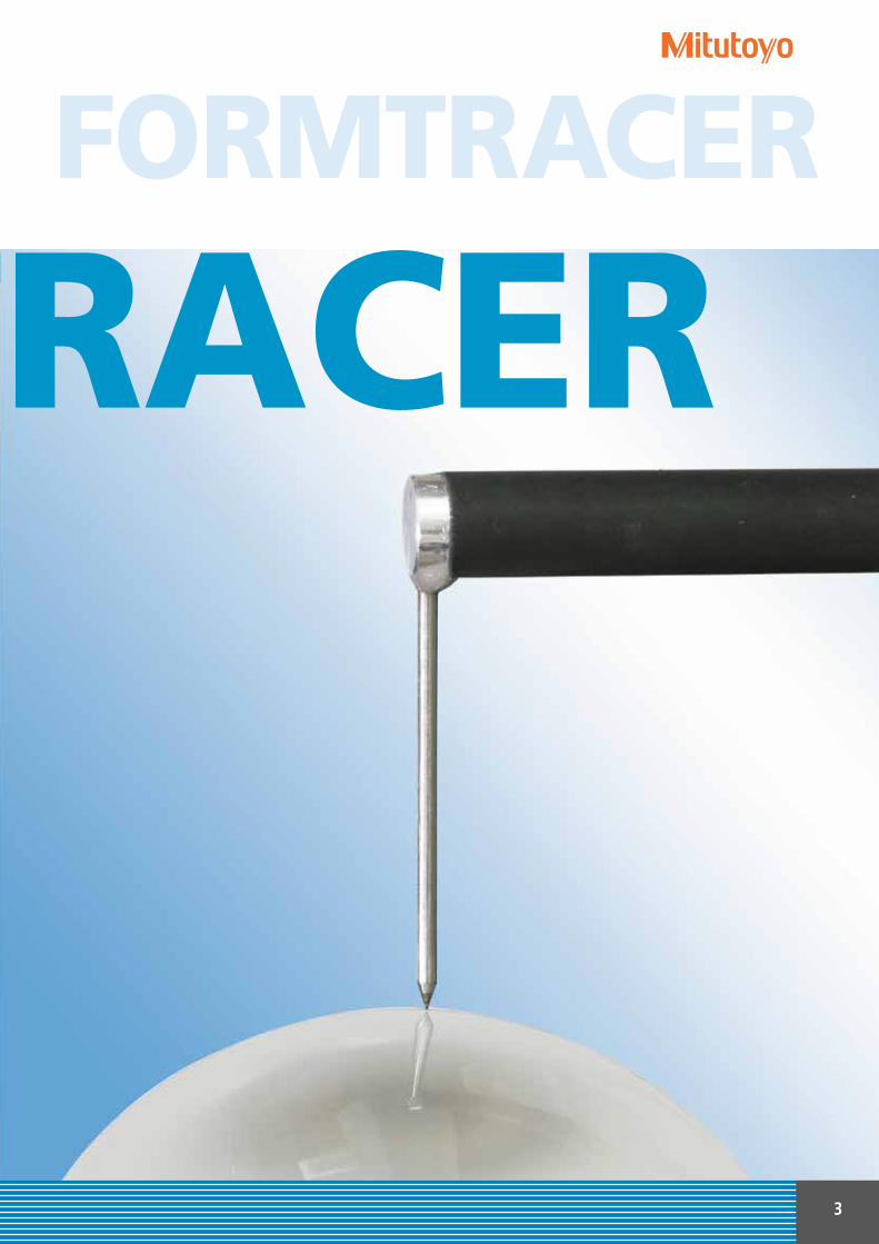
FORMTRACER: COMPLETE SURFACE AND CONTOUR
MEASUREMENT, COMBINED IN ONE SPACE-SAVING SYSTEM.

2
Intelligent combinations for efficient measuring.
Meticulous surface and contour measurement to the highest quality standards requires enormous technical competence. As an international supplier of a wide range of production measurement technology, Mitutoyo sets the standard in knowledge and competence in its field. This applies in particular to the economical combination of both measuring processes into a single system that can be adapted to your requirements. FORMTRACER machines meet the requirements of unlimited capacity for surface and contour measurement – intelligently combined into one space-saving, economical device.
This brochure gives you an overview of the broad and intelligently structured Mitutoyo range of models for combined surface and contour measurement. Here you will find the perfect FORMTRACER configuration for roughness and waviness testing as well as for the evaluation of profiles on the production line itself, in the measuring room or in the test laboratory. From semi-automatic through to CNC-controlled high-performance systems, fast, safe and efficient guidance on the best solution for your specific measurement needs. You can request to see more detailed single-product brochures on the FORMTRACER of your choice, the range of accessories and software available.
Whatever you choose: with a Mitutoyo measuring system, you will secure the experience, competence and performance of an internationally successful technology leader, and customer-oriented service worth getting excited about.
Mitutoyo: all the benefits, intelligently combined!COM
BIN
ED M
EASU
RIN
G
MA
CHIN
ES
FORMTRACERSurface and contour measurement in a single device. No compromise, with all the options.
3
FORMTRACER
FORMTRACER

4
The best connections for versatile applications.FORMTRACER variants.Measuring method Model Brief profile Specific features
FORMTRACER SV-C 3200
FORMTRACER SV-C 4500
FORMTRACER CS-3200
FORMTRACER EXTREMESV-C4500CNC
FORMTRACER EXTREME CS-5000 CNC
CS-H 5000 CNC
Intelligent combination of two complete systems for contour measurement and comprehensive surface analysis.
Powerful device with combined sensor for efficient simultaneous measuring of contour and surface in one measuring process.
Powerful CNC-capable connection of two unlimited contour measurement and comprehensive surface analysis systems. With CNC control in all axes for efficient series testing.
Sem
i-au
tom
atic
CN
C
For particularly stringent requirements in contour measurement in the measuring room and laboratory. With dual stylus system for upward/downward contour measurement.
FORMTRACER EXTREME SV-C 4500 CNC
SV-C
(sep
arat
e se
nso
r)
Sem
i-au
tom
atic
CN
C
CS
(co
mb
ined
sen
sor)
SV-C
FORMTRACER SV-C 3200FORMTRACER SV-C 4500
CNC reference system with a large measuring range for maximum precision tasks in research, development and quality assurance.The high end system with integrated laser holoscale for maximum precision in the test room and laboratory.

5
Measuring method Model Brief profile Specific features
SV-C 3200 S4 100 mm 300 mm 600 x 450 mmSV-C 3200 H4 100 mm 500 mm 600 x 450 mmSV-C 3200 W4 100 mm 500 mm 1000 x 450 mmSV-C 3200 L4 100 mm 700 mm 1000 x 450 mm
SV-C 3200 S8 200 mm 300 mm 600 x 450 mmSV-C 3200 H8 200 mm 500 mm 600 x 450 mmSV-C 3200 W8 200 mm 500 mm 1000 x 450 mmSV-C 3200 L8 200 mm 700 mm 1000 x 450 mm
CS-3200 S4 100 mm 300 mm 600 x 450 mm
SV-C 4500 S4 100 mm 300 mm 600 x 450 mmSV-C 4500 H4 100 mm 500 mm 600 x 450 mmSV-C 4500 W4 100 mm 500 mm 1000 x 450 mmSV-C 4500 L4 100 mm 700 mm 1000 x 450 mm
SV-C 4500 S8 200 mm 300 mm 600 x 450 mmSV-C 4500 H8 200 mm 500 mm 600 x 450 mmSV-C 4500 W8 200 mm 500 mm 1000 x 450 mmSV-C 4500 L8 200 mm 500 mm 1000 x 450 mm
SV-C 4500 CNC S 200 mm 300 mm 1000 x 450 mmSV-C 4500 CNC H 200 mm 500 mm 1000 x 450 mm
CS-5000 CNC S8 200 mm 300 mm 1000 x 450 mmCS-5000 CNC H8 200 mm 500 mm 1000 x 450 mm
Measuring range Height Base plateModel X axis adjustment dimensions
• Two separate, interchangeable sensors• Digital scale• Motor-driven height-adjustment of the Z axis• Fully-automatic sequence of measuring programs
• A combined sensor• Digital scale• Motor-driven height adjustment of the Z axis• Fully-automatic sequence of measuring programs
• Two separate, interchangeable sensors• Dual stylus contour measuring unit• Motor-driven height adjustment of the Z axis• Fully automatic sequence of measuring programs
• Powerful as two separate, fully CNC instruments.• Measurement of long distances in Z2-axis for models without α axis.• Each axis has a drive speed up to 200 mm/s.• Dual stylus system for upward and downward contour measurement at doubled sided contours.
• A combined sensor• Laser holoscale• Vibration-absorbing air bearings• Up to six axes CNC controlled
FORMTRACER CS-3200 FORMTRACER CS-5000 CNC
Mitutoyo has a wide range of models for different fields of application.
CS
CS-H 5000 CNC 200 mm 300 mm 1000 x 450 mm

6
FORMTRACER technology:Simply more capable.
Surface testingContour testing Contour and surface testing
SV-C System
Measurement in two separate measuring sequencesFORMTRACER variants with SV-C system are fitted with two separate interchangeable sensors for separate surface and contour measurement. Evaluation and documentation of test results can either be separate or combined using Mitutoyo’s FORMTRACEPAK software.
CS System
Measurement in a single measuring sequenceFORMTRACER CS machines check the surface and contour of a workpiece in a single measuring sequence. They have a combined sensor for both processes. The FORMTRACEPAK software can either carry out separate or joint evaluation and documentation.
+ =
TWO in ONE – two measuring processes in a single system
FORMTRACER machines open up the whole range of surface and contour measurement techniques – intelligence and compactness, combined in a single space-saving device. FORMTRACER machines, depending on the version, will also operate either with two separate measuring sequences for each process – or, with combined sensor, in a single measuring sequence for simultaneous surface and contour testing.
Laser holoscale
Several models in the FORMTRACER series are fitted with highly sophisticated laser holoscales for maximum precision work. Laser holoscales are glass scales which use the diffraction phenomenon of light to make the measurement by projecting an interference pattern from a laser onto a holographic screen. A photoelement then transforms the pattern into an electrical sinusoidal wave. This innovative technology can achieve highest resolutions over the entire measuring range.

7
Tilting of the measuring system
New design principles for even greater stability
Higher stability and guidance quality due to modern design processes: FORMTRACER measuring machines are designed using the finite element method (FEM). This ensures considerably greater rigidity and straightness of the guide elements and effective vibration reduction – essential factors in giving these systems their impressive power.
Control in up to six axes
Control in up to six axes – including tilting and rotational movements – means that the CNC systems in the FORMTRACER series can position workpieces extremely quickly and therefore achieve optimum throughput rates during series measurements. Particularly useful is the option of controlling all axes via the double joystick supplied as standard.
Θ1
Θ2
Collision prevention
FORMTRACER machines in the SV-C, CS-3200 and CS-5000 CNC series are equipped with collision prevention.
Removable arm

8
FORMTRACER SV-C 3200 and SV-C 4500.Double benefits, no compromise.
FORMTRACER SV-C 3200
• Two separate sensors for contour and surface analysis• Expanded contour measuring range of Z1 = 60 mm as standard• Surface measurement range of 800 µm as standard• Easy exchange of magnetic contour stylus arm gives excellent flexibility• Measurement and analytical software FORMTRACEPAK• Excellent accuracy and resolution• Highest positioning speed up to 80 mm/s
• Dual stylus contour measuring unit for upward / downward measurement at double sided contours• Contour measuring range of Z1 = 60 mm as standard• Surface measurement range of 800 µm as standard• Measuring force controlled by software FORMTRACEPAK• Easy exchange of magnetic contour stylus arm gives excellent flexibility• Highest accuracy and resolution• Highest positioning speed up to 80 mm/s
FORMTRACER SV-C 4500
As powerful as two separate specialized systems.Economically combined into a single device.
High accurate system for high-precision testing in measuring rooms and laboratories.
SV-C
320
0SV
-C 4
500
Measuring range: X axis 100/200 mmZ2 axis 300/500/700 mm
CONTOUR MEASUREMENT: Measuring range Z1 60 mmResolution Z1 0.04 µmAccuracy X [S4,H4,W4, L4] ±(0.8+0.01L) µmAccuracy X [S8,H8,W8, L8] ±(0.8+0.02L) µmAccuracy Z1 ±(1.4+0.02H) µmStraightness X 0.8 µm/100 mm 2 µm /200 mm
SURFACE MEASUREMENT:Measuring range Z1 800/80/8 µmResolution Z1 up to 0.0001 µmStraightn. X [SHWL4] (0.05+0.0001L) µmStraightn. X [SHWL8] (0.1+0.002L)µm
Measuring range:X axis 100/200 mmZ2 axis 300/500/700 mm
CONTOUR MEASUREMENT:Measuring range Z1 60 mmResolution Z1 0.02 µmAccuracy X [S4,H4,W4,L4] ±(0.8+0.01L) µmAccuracy X [S8,H8,W8,L8] ±(0.8+0.02L) µmAccuracy Z1 ±(0.8+0.02H) µmStraightness X 0.8 µm/100 mm 2 µm/200 mm
SURFACE MEASUREMENT:Measuring range Z1 800/80/8 µmResolution Z1 up to 0.0001 µmStraightn. X [SHWL4] (0.05+0.001L) µmStraightn. X [SHWL8] (0.1+0.002L) µm
Measuring and analytical software
SV-C 3200

9
FORMTRACERSemi-automatic
SV-C 4500

10
FORMTRACER EXTREME SV-C 4500 CNC.Production-ready measurement competence.
SV-C 4500 CNCFORMTRACER EXTREME SV-C 4500 CNCPerfect combination of two powerful systems for contour and surface analysis. With CNC control in six axes for comprehensive serial measurements.
Control in up to 6 axes
Measuring range: X axis 200 mmZ2 axis 300/500 mm
CONTOUR MEASUREMENT:Measuring range Z1 60 mm Measuring range Z2 300/500 mmAccuracy X ±(0.8+4L /200) µmAccuracy Z1 ±(0.8+0.02H) µmAccuracy Z2 for ±(1.5+0.01H) µm model w/o α-axisStraightness X 2 µm/200 mm
SURFACE MEASUREMENT: Measuring range Z1 800/80/8 µmResolution Z1 up to 0.0001 µmStraightness X 0.5 µm/200 mm
Traversing speed: CNC max. 200 mm/sJoystick 0-60 mm/s
• Powerful as two separate, fully CNC instruments.• Measurement of long distances in Z2-axis for models without α axis.• Each axis has a drive speed up to 200 mm/s.• Dual stylus system for upward and downward contour measurement at doubled sided contours.• It´s variable contour measuring force is controlled by software FORMTRACEPAK.• The contour drive unit is equipped with an arc encoder detector giving excellent accuracy and resolution in Z1-axis.• Perfectly made for increased throughput of multiple profile and workpiece measurement tasks.• The detector unit incorporates an anti-collision safety device, causing it to automatically stop if its main body collides with a workpiece or jig.
Measuring and analytical software

11
FORMTRACERCNC
Surface Roughness drive unit Contour drive unit

12
FORMTRACER CS-3200.Double the value – half the cost.
CS-3200FORMTRACER CS-3200Simultaneous surface and contour testing over a wide measuring range in a single pass. For maximum savings in time and cost.
Measuring range: X axis 100 mmZ1 axis 5 mm
Accuracy: X axis ±(0.8+0.01L) µmZ1 axis ±(1.5+0.02H) µm
Resolution: X axis 0.05 µmZ1 axis 0.08 µm/5 mm 0.0008 µm/0.05 mm
• A combined sensor• Inclination of the sensor up to ±45º possible• Straightness of the X axis (feed): 0.2 µm/100 mm• Ceramic guides on the X axis (feed)• Inductive measuring system in the Z1 axis• Motor-driven height adjustment of the Z2 axis• Automatic raising and lowering of the probe tip• Joystick operation for moving all axes and among other things for starting and stopping the measuring process• Measurement and analytical software FORMTRACEPAK supplied as standard• Data transmission via USB interface• ABS scale in the Z2 axis• High traversing speed• Automatic calibration function• Collision prevention
PLEASE NOTE: A start-up system (relocation detection sensor) is an integral security feature of this machine and will disable its operation if subject to relocation or strong vibration. Please be advised to contact your nearest Mitutoyo Service Centre as soon as possible or in advance of such circumstance.
Measuring and analytical software

13
FORMTRACERSemi-automatic

14
FORMTRACER EXTREME CS-5000 CNC/CS-H 5000 CNC.Setting the standards.
CS-5000 CNC/CS-H 5000 CNCFORMTRACER EXTREME CS-5000 CNC/CS-H 5000 CNCPerfect CNC precision for research, development, quality assurance and series testing. Better, high speed performance and a wide measuring range.
Drive in up to 6 axes
CS-5000 CNCMeasuring range: X axis 200 mmZ1 axis 12 mm / 24 mmZ2 axis 300 / 500 mm
Accuracy: X axis ±(0.3+0.02H) µmZ1 axis ±(0.3+0.02H) µm
Resolution: X axis 0.00625 µmZ1 axis 0.0008 µm
Traversing speed: CNC max. 200 mm/sJoystick 0-50 mm/s
• A combined sensor• Laser holoscale in the X and Z axes• Ceramic guides on the X axis (feed)• Drive is possible in up to six axes (CS-H up to 5 axes)• Active control of the probe system• Automatic positioning of the workpiece with controllable rotary table and Y table• Vibration-absorbing air bearing• Double joystick operation for programming all six axes and for starting and stopping the measuring process, etc.• Measurement and analytical software FORMTRACEPAK supplied as standard • Data transmission via USB interface• Highest accuracy with CS-H 5000 CNC
CS-H 5000 CNC Measuring range: X axis 200 mmZ1 axis 12 mm / 24 mmZ2 axis 300 mm
Accuracy: X axis ±(0.16+0.001L) µmZ1 axis ±(0.07+0.02H) µm
Resolution: X axis 0.00625 µmZ1 axis 0.0008 µm

15
CS-5000 CNC/CS-H 5000 CNC
FORMTRACERCNC

16
With all systems in the SV-C and CS series, multilanguage FORMTRACEPAK software covers machine control and the evaluation and documentation of test results. Depending on the system used, FORMTRACEPAK also controls the machine axes.
This software solution offers the user the full program of maximum efficiency surface and contour measurement with versatile evaluation and documentation options. Some examples follow:
• Automatic measurement program sequences• Best fit for automatic measuring sequence• Representation of results as a drawing and table• Graphic representation of contour or surface profile• Construction of help geometries• Contour comparison• Freely-definable tolerance ranges• Editing function• Automatic storage of the measurement results• Layout editor for representation of the test results• Automatic calibration function• Archiving of calibration data
Software package
Expansion module
Module for statistical measurement data processing and analysis, and storage of measured data.
MeasurLink
Software FORMTRACEPAK

17
All FORMTRACER machines are supplied as standard with perfectly configured software tailored to the specific performance profiles.
Profile Analysis Function
• Various commands including the point command (10 kinds), line command (6 kinds), and circle command (6 kinds) are provided to cover the basic elements of analysis. Standard calculation commands that combine these elements for angle, pitch, and distance calculations are also provided. The display method used by additional commands that are not regularly used can be optionally tailored by the customization function, e.g. "Hide", can be applied to the calcula-tion command button to suit the application environment.
• The step from performing a single measurement using the intuitive menu functions to creating a part program is easily done with a few mouse clicks.
• Calculation results will be output as text (in the csv or txt format). The geometrical measurement data can be either output as a text file of point-series data or a CAD file (in the DXF or IGES format) or copied onto the clipboard. It is also possible to use some commercial documentation software and statistical processing software to share the data on a PC that is not equipped with Mitutoyo-original analysis software or if reverse engineering is intended with CAD.
Surface Roughness Analysis Function
• Using the surface roughness measurement data it is possible to conduct analysis that conforms to global standards including EN ISO, VDA, JIS, ANSI, MOTIF, etc.
• This software has integrated not only parameter calculating functions but also comprehensive graphical analysis functions, which can be widely used in daily quality control and R&D operations.
• Also enhanced with the data correction function (applicable to inclination and a curved surface) and data elimination function, etc.
Measurement Control
• The Measurement Control screen has various command buttons appropriately arranged. They are required for creating and executing measurement procedures (part programs). Since the buttons and display areas not frequently used can be optionally set for display or no-display, the operator is permitted to arbitrarily customize the screen layout as easily as possible for operation.
• The “Workpiece Identification Function”, for example, that detects the amount of offset brought up during datum setting and mechanically fine-adjusts each axis to the optimum setting position for the measurement, as well as the “Coordinate System Alignment” com-mands that generate the optimum coordinate system for each measurement part, allow fully automatic running.
• With the multi-axis translation command that simultaneously controls the movement along a maximum of six axes it is now possible to reduce the operation time required by the measuring instrument to a minimum and to further reduce the tracing time.
• For measuring multiple parts arranged on the palette, the use of the multiple-part loop function that repeats a set of movement, measurement, and analysis commands can reduce the time required to create the specific measurement steps.

18
Possible combinations of probe components for the FORMTRACER models SV-C 3200, SV-C 4500 and SV-C 4500 CNC.
Probe tips for surface measurement*
For small holes 12AAC733 (2 µm)12AAB405 (5 µm)12AAB417 (10 µm)
0.4
1.2
Ø0.3
Detail A
Ø2.
4 8.9
Ø0.
6
2.5
37.744.2
Colour marking
Detail A
Detail A
60º
7.6
6.4
37.743.8
Ø1.2
Ø2.4
Detail A
Colour marking
Colour marking
Detail AØ2.4
87.7 0.9
Ø1.2
94.7
5.2
Detail A
Ø2.4
137.7 0.9
Ø1.2
144.7
5.2
Colour marking
Detail A
Detail A
Colour marking
Detail A
Detail A
33.8
5.2
Ø1.2
Ø2.4Ø2.
437.745.2
Detail A
Colour marking
Detail AA
37.7 0.9
Ø0.6
45
7.6
10
Ø2.
4
Ø2.
4
60º
60º
60º
60º
60º
60º
For deep holesX 2 probes 12AAC740 (2 µm)12AAB413 (5 µm)12AAB425 (10 µm)
Standard 12AAC731 (2 µm)12AAB403 (5 µm)12AAB415 (10 µm)
0.4
1.2
Ø0.3
Detail A
Ø2.
4 8.9
Ø0.
6
2.5
37.744.2
Colour marking
Detail A
Detail A
60º
7.6
6.4
37.743.8
Ø1.2
Ø2.4
Detail A
Colour marking
Colour marking
Detail AØ2.4
87.7 0.9
Ø1.2
94.7
5.2
Detail A
Ø2.4
137.7 0.9
Ø1.2
144.7
5.2
Colour marking
Detail A
Detail A
Colour marking
Detail A
Detail A
33.8
5.2
Ø1.2
Ø2.4Ø2.
437.745.2
Detail A
Colour marking
Detail AA
37.7 0.9
Ø0.6
45
7.6
10
Ø2.
4
Ø2.
4
60º
60º
60º
60º
60º
60º
For deep holesX 3 probes 12AAC741 (2 µm)12AAB414 (5 µm)12AAB426 (10 µm)
For deep grooves 12AAC737 (2 µm)12AAB407 (5 µm)12AAB419 (10 µm)
Eccentric 12AAC739 (2 µm)12AAB412 (5 µm)12AAB424 (10 µm)
0.4
1.2
Ø0.3
Detail A
Ø2.
4 8.9
Ø0.
6
2.5
37.744.2
Colour marking
Detail A
Detail A
60º
7.6
6.4
37.743.8
Ø1.2
Ø2.4
Detail A
Colour marking
Colour marking
Detail AØ2.4
87.7 0.9
Ø1.2
94.7
5.2
Detail A
Ø2.4
137.7 0.9
Ø1.2
144.7
5.2
Colour marking
Detail A
Detail A
Colour marking
Detail A
Detail A
33.8
5.2
Ø1.2
Ø2.4Ø2.
437.745.2
Detail A
Colour marking
Detail AA
37.7 0.9
Ø0.6
45
7.6
10
Ø2.
4
Ø2.
4
60º
60º
60º
60º
60º
60º
Colour marking
Detail A
90
0,937,7
7,6
44,7
Ø 2,
4
Ø 1,2
5,2
A
Version Dimensions Tip detail Version Dimensions Tip detail
* Extract from the wide range of styli.

Applicable arms for SV-C3200, SV-C4500, SV-C4500 CNC
Eccentric 12AAQ762
AB-37
AB-31
AB-33
Straight 12AAM101
Small hole 12AAM103
Applicable styli for SV-C3200, SV-C4500, SV-C4500 CNC
19
For contour measurementVersion Dimensions Designation H
Applicable styli for SV-C3200, SV-C4500, SV-C4500CNC**
13015
Ø8
15
Ø3
Stylus
Ø8
14525
95Stylus
H
H
H
H
H
H
Saphir
5513
Ø1.
6 Ø4
0.4
5520
Ø3 Ø
5
1
55
Ø4
2.5
5012.50.
4
Ø1.
6
Ø6
1
5020
Ø3
Ø6
2.5 50
40
Ø4
Ø8
15
Ø8
155
40
Stylus
18515
Ø8
Stylus
Flat on one side
Cross-ground
Knife edge
Conical
Ball
13015
Ø8
15
Ø3
Stylus
Ø8
14525
95Stylus
H
H
H
H
H
H
Saphir
5513
Ø1.
6 Ø4
0.4
5520
Ø3 Ø
5
1
55
Ø4
2.5
5012.50.
4
Ø1.
6
Ø6
1
5020
Ø3
Ø6
2.5 50
40
Ø4
Ø8
15
Ø8
155
40
Stylus
18515
Ø8
Stylus
SPH-51 6 mm SPH-61 12 mm SPH-71 * 20 mm SPH-81 30 mm SPH-91 42 mm
SPH-52 6 mm SPH-62 12 mm SPH-72 20 mm SPH-82 30 mm SPH-92 42 mm
SPH-53 6 mm SPH-63 12 mm SPH-73 20 mm SPH-83 30 mm SPH-93 42 mm
SPH-55 6 mm SPH-65 12 mm SPH-75 20 mm SPH-85 30 mm SPH-95 42 mm
* Standard accessory** Extract from the wide range of styli.
SPH-54 6 mm SPH-64 12 mm SPH-74 20 mm SPH-84 30 mm SPH-94 42 mm
Applicable styli for SV-C4500, SV-C4500 CNC
Both sides conical12AAM095
Both sides conical 12AAM096
Both sides conical 12AAM097
SPHW-56 20 mm
SPHW-66 32 mm
SPHW-76 48 mm
Both sides small hole 12AAM108
Both sides small hole 12AAM109
Both sides small hole 12AAM110
SPHW-31 2.4 mm
SPHW-32 5 mm
SPHW-33 9 mm
Version Dimensions Designation H
Small hole
Small hole
Small hole
SPH-41 2 mm
SPH-42 4 mm
SPH-43 6.5 mm

20
Possible styli with the FORMTRACER model CS-3200.
Styli for surface and contour measurement
• Radius of tip curvature: 2 µm• Tip form: 60° cone• Tip material: Diamond• For contour/surface roughness measurement• Measurable depth: 7 mm max.
Standard stylus(No.12AAD554)
• Radius of tip curvature: 25 µm• Tip form: 30° cone• Tip material: Sapphire• For contour measurement• Measurable depth: 7 mm max.
Cone stylus(No.12AAD552)
• Radius of tip curvature: 2 µm• Tip form: 60° cone• Tip material: Diamond• For contour/surface roughness measurement• Applicable hole: ø 2 mm min. • Measurable depth: 15 mm max.
Small hole stylus(No.12AAD556)
• Radius of tip curvature: 2 µm• Tip form: 60° cone• Tip material: Diamond• For contour/surface roughness measurement• Offset from center line: 15 mm
Eccentric type stylus(No.12AAD558)
• Radius of tip curvature: 2 µm• Tip form: 60° cone• Tip material: Diamond• For contour/surface roughness measurement• Measurable depth: 20 mm max.
• Radius of tip curvature: 5 µm• Tip form: 40° cone• Tip material: Diamond• For contour/surface roughness measurement
Deep groove stylus(No.12AAD560)
2x-long stylus*1
(No.12AAD562)
ø1.2
66.5
ø3
1 59
60°
ø43.210 8
(6.5)
30°
ø3
66.5591
3.2
ø4810
(6.5)
60°0.6 (6.5)59
3.2
ø4
9ø1.2
10 0.4
66.1
24.84
60°
ø3
ø1.2
ø4
67.5
3.2
ø4
59
(8)
10
18 21 (6.5)
60°
23
3.2
ø4
21
1 5966.5
ø1.2
ø3
(6.5)
Standard accessory
*1: Measuring force is 4mN and the Z1 measuring range and resolution is double that of the standard stylus.
DimensionsType
136.5
ø3
ø1.2
1
3.2ø4
12.5
129
14.5
40°
(6.5)
Specifications
Standard accessory

21
Possible styli with the FORMTRACER models CS-5000 CNC and CS-H 5000 CNC.
Styli for surface and contour measurement
Standard12AAD543
Ball tip12AAD544
12AAD651 12AAD652
107
65.95
(31.5)
35.95
74.51
(6.5
)
(6.8
)
Ø4
Ø1.2
Ø6
40º12
.5 Ø1.2
Ø6
12.7
5
Ball Ø0.5 mm
(31.5)
145.95115.95
154.51
187
Ø6
(19)
Ø4 Ø1.2
Ø6
40º
25
Ø1.2
Ø6
25.2
5
Ball Ø0.5 mm
6 15 /10
35.95 65.95
Ø4
Ø6
1.6
(1.1
)
74.5 (31.5)
106.6 / 106.40.6
40º
0.4 Ø1.
2
0.4
40º
0.6 Ø0.
6
Ø6
40º
16
Ø4Ø6
12.5
(6.5
)
35.95
Ø1.2
65.95
74.5 (31.5)3109
107
65.95
(31.5)
35.95
74.51
(6.5
)
(6.8
)
Ø4
Ø1.2
Ø6
40º
12.5 Ø1.2
Ø6
12.7
5
Ball Ø0.5 mm
(31.5)
145.95115.95
154.51
187
Ø6
(19)
Ø4 Ø1.2
Ø6
40º
25
Ø1.2
Ø6
25.2
5Ball Ø0.5 mm
6 15 /10
35.95 65.95
Ø4
Ø6
1.6
(1.1
)
74.5 (31.5)
106.6 / 106.40.6
40º
0.4 Ø1.
2
0.4
40º
0.6 Ø0.
6
Ø6
40º
16
Ø4Ø6
12.5
(6.5
)
35.95
Ø1.2
65.95
74.5 (31.5)3109
Type Dimensions Tip detail Additional for CS-H5000CNC
Standard
Double length
For small holes
Eccentric
107
65.95
(31.5)
35.95
74.51
(6.5
)
(6.8
)
Ø4
Ø1.2
Ø6
40º
12.5 Ø1.2
Ø6
12.7
5
Ball Ø0.5 mm
(31.5)
145.95115.95
154.51
187
Ø6
(19)
Ø4 Ø1.2
Ø6
40º
25
Ø1.2
Ø6
25.2
5
Ball Ø0.5 mm
6 15 /10
35.95 65.95
Ø4
Ø6
1.6
(1.1
)
74.5 (31.5)
106.6 / 106.40.6
40º0.
4 Ø1.
2
0.4
40º
0.6 Ø0.
6
Ø6
40º
16
Ø4Ø6
12.5
(6.5
)
35.95
Ø1.2
65.95
74.5 (31.5)3109
12AAJ037
107
65.95
(31.5)
35.95
74.51
(6.5
)
(6.8
)
Ø4
Ø1.2
Ø6
40º
12.5 Ø1.2
Ø6
12.7
5
Ball Ø0.5 mm
(31.5)
145.95115.95
154.51
187
Ø6
(19)
Ø4 Ø1.2
Ø6
40º
25
Ø1.2
Ø6
25.2
5Ball Ø0.5 mm
6 15 /10
35.95 65.95
Ø4
Ø6
1.6
(1.1
)
74.5 (31.5)
106.6 / 106.40.6
40º
0.4 Ø1.
2
0.4
40º
0.6 Ø0.
6
Ø6
40º
16
Ø4Ø6
12.5
(6.5
)
35.95
Ø1.2
65.95
74.5 (31.5)3109
Standard12AAD545
Ball tip12AAD546
107
65.95
(31.5)
35.95
74.51
(6.5
)
(6.8
)
Ø4
Ø1.2
Ø6
40º
12.5 Ø1.2
Ø6
12.7
5
Ball Ø0.5 mm
(31.5)
145.95115.95
154.51
187
Ø6
(19)
Ø4 Ø1.2
Ø6
40º
25
Ø1.2
Ø6
25.2
5
Ball Ø0.5 mm
6 15 /10
35.95 65.95
Ø4
Ø6
1.6
(1.1
)
74.5 (31.5)
106.6 / 106.40.6
40º
0.4 Ø1.
2
0.4
40º
0.6 Ø0.
6
Ø6
40º
16
Ø4Ø6
12.5
(6.5
)
35.95
Ø1.2
65.95
74.5 (31.5)3109
Ø1.2
Ø6
60º
25
12AAJ039 12AAJ041
12AAD653
Detector Nosepiece

22
Accessories
Automatic leveling tableFor automatically aligning the workpiece with the reference plane. After determining the workpiece inclination by the measuring system, the software calculates the optimal automatic setting of the levelling table.
For significantly easier manual fine positioning of the workpiece using integral Digimatic micrometers. The information required for alignment is provided and displayed by the software. The triple-axis adjustment table also enables ideal alignment of cylindrical workpieces to the measurement axis – measurement errors by deviation from the axis of the parts tested can therefore be reliably avoided.
As an alternative to manual alignment, FORMTRACEPAK software, in combination with CNC accessories, will automatically align workpieces and ensure optimum measurement conditions.
Aligned Not aligned
Measurement end point
Path traced by stylus
Measurement start point
Measured contour
θ1 axis θ2 axis Y table 2D/3D auto-levelling table
Examples of accessories for CNC function support
Manual three-axis adjustment table
Combination Y table and θ1 axis

23
Rotary vice XY levelling table (DIGIMATIC) ViceXY table
218-001 218-003 178-052-1 178-019
Find additional product literature and our product catalogue
www.mitutoyo.eu Mitutoyo Europe GmbH
Borsigstraße 8-10 41469 Neuss
Tel. +49 (0) 2137-102-0 Fax +49 (0) 2137-102-351
[email protected] www.mitutoyo.eu
© M
ITUTO
YO/D
03/
17 P
RE12
37(7
)
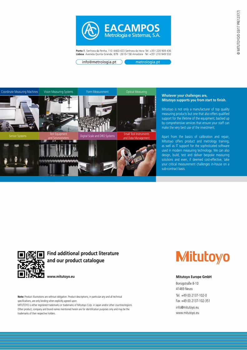
Whatever your challenges are, Mitutoyo supports you from start to finish.
Mitutoyo is not only a manufacturer of top quality measuring products but one that also offers qualified support for the lifetime of the equipment, backed up by comprehensive services that ensure your staff can make the very best use of the investment.
Apart from the basics of calibration and repair, Mitutoyo offers product and metrology training, as well as IT support for the sophisticated software used in modern measuring technology. We can also design, build, test and deliver bespoke measuring solutions and even, if deemed cost-effective, take your critical measurement challenges in-house on a sub-contract basis.
Note: Product illustrations are without obligation. Product descriptions, in particular any and all technical specifications, are only binding when explicitly agreed upon.MITUTOYO is either registered trademarks or trademarks of Mitutoyo Corp. in Japan and/or other countries/regions. Other product, company and brand names mentioned herein are for identification purposes only and may be the trademarks of their respective holders.
Coordinate Measuring Machines
Sensor Systems
Vision Measuring Systems
Test Equipment and Seismometers
Form Measurement
Digital Scale and DRO Systems
Optical Measuring
Small Tool Instruments and Data Management