continuously reinforced concrete and unpaved …
TRANSCRIPT

PREPARED BY: BUREAU OF MAINTENANCE AND OPERATIONS
ASSET MANAGEMENT DIVISION P.O. Box 3437
HARRISBURG, PENNSYLVANIA 17105-3437 (717) 787-6899
PUB 343 (4-21)
CONTINUOUSLY REINFORCED CONCRETE AND UNPAVED ROADS
CONDITION SURVEY FIELD MANUAL PUBLICATION 343
APRIL 2021


COMMONWEALTH OF PENNSYLVANIA DEPARTMENT OF TRANSPORTATION
CONTINUOUSLY REINFORCED CONCRETE PAVEMENT
AND UNPAVED ROADS
CONDITION SURVEY FIELD MANUAL
APRIL 2021
PUBLICATION 343


i
TABLE OF CONTENTS
INTRODUCTION ..................................................................................................................1
SURVEY TECHNIQUES AND PROCEDURES..............................................................2 GENERAL: ..............................................................................................................................2 RAMPS: ..................................................................................................................................4 BRIDGES: ...............................................................................................................................4 CRC PAVEMENTS:.................................................................................................................4 UNPAVED ROADS: .................................................................................................................4
DUTIES AND RESPONSIBILITIES..................................................................................5
SAFETY FIRST: .......................................................................................................................5 DRIVER: .................................................................................................................................5 EVALUATOR: .........................................................................................................................5 QUESTIONS FROM THE PUBLIC:............................................................................................6
EQUIPMENT NEEDED .......................................................................................................7
EXTENT ESTIMATION ......................................................................................................8
COMPLETION OF CONDITION SURVEY INPUT FORM ........................................9
IDENTIFICATION SECTION: ....................................................................................................9 EVALUATION SECTION: .........................................................................................................9 CRC PAVEMENT SURVEY FORM ........................................................................................10 UNPAVED ROADS SURVEY FORM .......................................................................................11
DEFINITIONS ......................................................................................................................12
CONDITION IDENTIFICATION GUIDE .....................................................................13
CRC PAVEMENTS ...........................................................................................................13 Longitudinal Joint Spalling ...........................................................................................14 CRC Transverse Cracking .............................................................................................16 Punchout .........................................................................................................................18 Bridge Approaches .........................................................................................................20 Damaged Terminal Joints .............................................................................................22 Rutting .............................................................................................................................24
UNPAVED ROADS ..........................................................................................................25
Corrugations ..................................................................................................................26 Loss of Aggregate Surface .............................................................................................28 Poor Drainage................................................................................................................30 Soft Areas ........................................................................................................................32


1
Introduction This manual is for use with the Pennsylvania Department of Transportation’s Pavement Condition Survey. The Pavement Condition Survey is a distress survey that provides quantified, location specific condition data on Pennsylvania’s network of approximately 40,000 centerline miles of state-owned highways. The data collected is used for the following: 1. To provide a uniform statewide condition evaluation that would improve decision
making. 2. To provide management with information and tools to monitor condition of the network,
assess future needs, establish county condition rankings and optimize investments. 3. To provide condition information to fulfill the requirements of Act 68 (1980) which
requires the allocation of maintenance funds to the individual counties based on needs. 4. To provide information for monitoring the performance of various pavement designs,
rehabilitation and maintenance techniques. 5. To provide information for identifying candidate projects for maintenance and
betterment programs. This manual covers distress conditions for Continuously Reinforced Concrete (CRC) Pavements and Unpaved Roads.
2
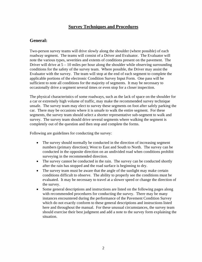
Survey Techniques and Procedures
General: Two-person survey teams will drive slowly along the shoulder (where possible) of each roadway segment. The teams will consist of a Driver and Evaluator. The Evaluator will note the various types, severities and extents of conditions present on the pavement. The Driver will drive at 5 – 10 miles per hour along the shoulder while observing surrounding conditions for the safety of the survey team. Where possible, the Driver may assist the Evaluator with the survey. The team will stop at the end of each segment to complete the applicable portions of the electronic Condition Survey Input Form. One pass will be sufficient to note all conditions for the majority of segments. It may be necessary to occasionally drive a segment several times or even stop for a closer inspection. The physical characteristics of some roadways, such as the lack of space on the shoulder for a car or extremely high volume of traffic, may make the recommended survey technique unsafe. The survey team may elect to survey these segments on foot after safely parking the car. There may be occasions where it is unsafe to walk the entire segment. For these segments, the survey team should select a shorter representative sub-segment to walk and survey. The survey team should drive several segments where walking the segment is completely out of the question and then stop and complete the forms. Following are guidelines for conducting the survey:
• The survey should normally be conducted in the direction of increasing segment
numbers (primary direction); West to East and South to North. The survey can be conducted in the opposite direction on an undivided road when conditions prohibit surveying in the recommended direction.
• The survey cannot be conducted in the rain. The survey can be conducted shortly after the rain has stopped and the road surface is beginning to dry.
• The survey team must be aware that the angle of the sunlight may make certain conditions difficult to observe. The ability to properly see the conditions must be evaluated. It may be necessary to travel at a slower speed or change the direction of the survey.
• Some general descriptions and instructions are listed on the following pages along with recommended procedures for conducting the survey. There may be many instances encountered during the performance of the Pavement Condition Survey which do not exactly conform to these general descriptions and instructions listed here and throughout the manual. For these unusual circumstances, the survey team should exercise their best judgment and add a note to the survey form explaining the situation.

3
Two-Lane Roadways: Evaluate two-lane roadways in one pass. In some cases, it may be advisable to also drive the segment in the opposite direction if the opposite shoulder cannot be seen or the condition of the other lane is substantially different. Complete one form for a two-lane roadway segment. A two-lane road with parking lanes on each side is considered a two-lane road. Three-Lane Roadways (Two Directions): Evaluate three-lane roadways in one pass in one direction, or one pass in each direction (two passes) if necessary. Complete one form for each three-lane roadway segment. Four-Lane Roadways: Evaluate four-lane roadways, divided roadways, in two passes; one pass in each direction. Each direction is a separate segment. The “width” block will indicate the width of the two lanes (the segment) in the direction being surveyed. The “Direction” block will indicate the direction of travel of the two lanes (the segment) being surveyed. Complete one form for each segment. Five-Lane Roadways: Evaluate five-lane roadways in two passes, one pass for each direction. Each direction is a separate segment. Include the center lane with the two lanes in the increasing segment direction. Include the extra lane with the segment in which it is located if the roadway is physically divided. The “Width” and “Direction” blocks will be as described in the Four-Lane Roadway section above. Complete one form for each segment. Six-Lane Roadways: Evaluate six or more lane roadways in multiple passes. Each pass should cover no more than three lanes. Seven or more lane roadways will require multiple passes in each direction. Each direction is a segment. The “Width” and “Direction” blocks will be as described in the Four-Lane Roadway section above. Complete one form for each segment.

4
Ramps: No separate evaluation will be made for ramps. The maintenance and rehabilitation of ramps is usually performed in conjunction with work on the main line. Do not evaluate ramp acceleration and deceleration lanes.
Bridges: Bridges are not surveyed with the rest of the segment in which they are located. Therefore, the bridge length should be excluded from the pavement length when determining percentages for extents. Evaluations should begin and end at the limits of the bridge superstructure. Bridge approach slabs, if any, are included with the pavement survey. Segments which are predominantly bridge, where the bridge is 50% or more of the segment length, are not surveyed; no survey form is generated.
CRC Pavements: Continuously Reinforced Concrete (CRC) Pavements are a distinct type of portland cement concrete pavement. CRC pavements do not have joints and are surveyed separate from rigid pavements. There are currently zero miles of CRC pavement in Pennsylvania. CRC is no longer approved for use, but the survey procedures in this manual will be maintained in case CRC comes back into use. Only Central Office Survey Teams receive training for conducting the CRC survey.
Unpaved Roads: Unpaved Roads are those road surfaces that are gravel, cinder or earth. Sometimes the surface has been stabilized, but it is still considered unpaved. There are approximately 150 miles of unpaved roads in Pennsylvania that are owned by the Department of Transportation. Only Central Office Survey Teams receive training for conducting the Unpaved Road survey.

5
Duties And Responsibilities
Safety First: First and foremost of the Survey Team’s responsibility is SAFETY! No matter how important the information obtained is, it is not worth more than the health or life of anyone. To conduct a safe survey, the Survey Team must be alert for potential problems. The Driver and the Evaluator must be alert at all times and utilize defensive driving skills.
Driver: The Driver’s first responsibility is to operate the vehicle in a safe, courteous manner in accordance with the laws of the Commonwealth. The Driver should operate the vehicle at a safe, convenient rate of speed from the beginning of the segment to the end. The Driver will assist with the survey by noting conditions only where safely possible. The Driver will locate a safe place to stop at the end of each segment and park while the Evaluator completes the electronic Condition Survey Input Form. The Driver will be responsible for determining the Team’s location using fixed points (intersections, bridges, etc.), the distance measuring instrument (DMI) and the Straight Line Diagrams (SLD). The Driver will keep records to assure that all segments are covered as planned and determine the Team’s routing to minimize non-productive travel.
Evaluator: The Evaluator should be seated behind the Driver wherever possible. This provides an unobstructed view of the pavement. The Evaluator will inform the Driver of the anticipated ending limit of the segment to be evaluated. The Evaluator will complete any missing information in the header of the electronic Condition Survey Input Form, including date and observers, before beginning the survey of each segment. The Evaluator will observe the pavement conditions. The Evaluator may find it helpful to discuss with and mention to the Driver conditions observed while conducting the survey. The Evaluator will complete the appropriate sections of the electronic Condition Survey Input Form, discussing the rating with the Driver, when the Driver has stopped the vehicle at the end of the segment. The completed Condition Survey Input Form should be a consensus of the Driver and the Evaluator where possible. The Evaluator will then save the completed form and the Team will proceed to the next segment. The Evaluator will also keep a list of discrepancies in the Straight Line Diagram or County Map. These discrepancies are to be reported to the Program Management & Quality Control Engineer.

6
Serious hazards to the motoring public should be reported to the Program Management & Quality Control Engineer as soon as possible. The PM & QC Engineer will contact the appropriate District unit to address the issue. If the PM & QC Engineer cannot be reached, any hazard or issue that requires immediate corrective action should be reported to the County Maintenance Manager.
Questions From The Public: It is imperative that the Survey Team answer questions from the public honestly and diplomatically in order to maintain good public relations. Inform the citizen that a condition survey is being conducted to better enable the Department of Transportation to repair those pavements most in need. Politely direct any specific complaints to the Assistant District Engineer for Maintenance or the County Maintenance Manager. It may be advisable to inform local police in some areas that a pavement survey is being conducted and the approximate dates.

7
Equipment Needed The following list of equipment is necessary to the proper performance of the CRC and Unpaved Roads Condition Survey.
1. State Car equipped with: a. Digital distance measuring instrument (DMI) which accurately determines
distance, b. Amber flashing warning beacon, c. Survey Sign on back of vehicle (ROAD SURVEY or PAVEMENT
SURVEY)
2. County Maps (paper or digital)
3. Straight Line Diagrams (paper or digital)
4. CRC and Unpaved Roads Condition Survey Field Manual
5. Clipboard
6. STAMPP application on tablet or laptop PC preloaded with eSTAMPP forms
7. Pens, pencils and tablet paper for taking notes
8. Hard hats and safety vests
9. Six-foot rule
10. File folders
11. String line at least 15 feet long
12. Tape measure at least 50 feet long

8
Extent Estimation This section contains information that will help in estimating the extent of various conditions that are based on length.
2000’ Segment 2500’ Segment Half-Mile Segment 3000’ Segment
Percentage Length Length Length Length
10 200’ 250’ 264’ 300’ 30 600’ 750’ 792’ 900’

9
Completion of Condition Survey Input Form
Identification Section: Most of this section will be preloaded to the field data collector. The information contained in the identification section should be quickly reviewed to make sure the information is correct. That information is:
Segment Identifier – The first three fields are the segment identifier: County Name State Route Number Segment Number Segment Length – The length of the segment in feet. Direction – The direction of the portion of the pavement being evaluated, coded as follows: B – when only one form is used for 2 or 3 lane sections, both directions N, E, S or W – when 4 or more lanes, indicates the direction of travel
Beginning Description – Narrative description of the segment beginning point Ending Description – Narrative description of the segment ending point Surface Type – 2 digit code describing the pavement type Predominant Width – The predominant pavement width, in feet, of the portion of the pavement being evaluated No. of Lanes – The number of travel lanes in the segment Observers – The code numbers of the Survey Team; OBS1 is the Evaluator, OBS2 is the Driver Survey Date – The date the segment is surveyed (shown in the body of the form)
Evaluation Section: The appropriate parts of this section will be completed depending on the type of pavement being evaluated. Each condition is noted by considering the severity level(s) present and the extent of each severity level. The input form allows up to 10 choices of severity and extent. There are three levels of severity, three levels of extent, plus “None.” There are less than 10 choices for a few conditions. The evaluation is made by checking up to two selections for each condition. Note that if “None” is checked, there should be no other checks for that condition. Note also that no

10
CRC Pavement eSTAMPP Survey Form
(No Image Available. A new CRC survey form will be developed if needed.)

11
Unpaved Roads eSTAMPP Survey Form
(Layout may change based on the current version of the STAMPP application)

12
two selections may be checked at the same severity; there may be two checks at the same extent at different severities. A second check is not necessary if a check in only one severity/extent adequately describes the condition. Check only medium and high severity if all three severity levels are present; even if low severity has the greatest extent. Any narrative remarks concerning the segment should be made in the “Remarks” section. Remarks can include unusual conditions not recorded in the Evaluation Section, hazards noted and reported to the County Maintenance Manager, or possible reasons for not evaluating a segment; construction, bridge, heavy traffic or congestion, etc.
Definitions Pavement – The portion of the roadway intended for regular vehicular traffic. Continuously Reinforced Concrete Pavement – A pavement with a Portland Cement Concrete riding surface and no joints. This is surface type 73. Unpaved Roads – Any road with a gravel, cinder or earth surface. Includes roads that have been treated with a dust palliative. This is surface types 20, 30 and 40. Joint – The interface between two distinct portions of pavement, or between the pavement and shoulder. One transverse joint extends across the width of one lane.

13
CONDITION IDENTIFICATION GUIDE
CRC PAVEMENTS

14
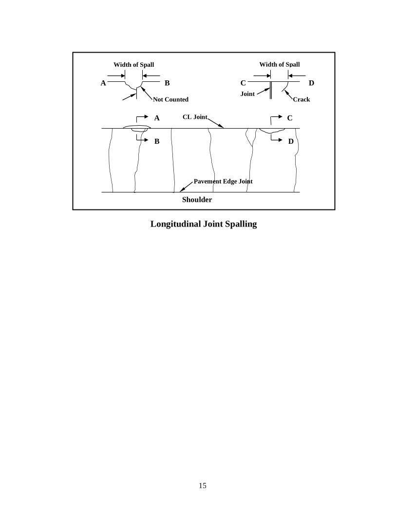
Longitudinal Joint Spalling Description: This condition is characterized by the cracking, breaking or chipping of slab edges adjacent to the longitudinal joint. This condition usually does not extend through the thickness of the slab but meets the joint at an angle. The spall may be currently filled with bituminous material. If so, record the width of the spall as the width of the bituminous material. Possible Causes: Longitudinal joint spalling is generally caused by low quality concrete at the joint in combination with low air content in the concrete, wet-dry and freeze-thaw cycling and traffic loads. Severity Levels: None: < 25 L.F., total all severities Low: Spall is < 1 in wide from edge of slab Medium: Spall is ≥ 1 in and ≤ 6 in wide from edge of slab. High: Spall is > 6 in wide from edge of slab. Extent: Record as the percentage of the length of the longitudinal joint for each severity
level. Note: • Count a spall that occurs at the intersection of a longitudinal joint and transverse joint
as Longitudinal Joint Spalling if the spall is predominantly along the longitudinal joint. • Evaluate both longitudinal joints if the segment has three lanes of CRC Pavement.
Include the length of both longitudinal joints in the extent estimation. • Record Longitudinal Joint Spalling only when the total of all longitudinal joint spalling
in the segment equals or exceeds 25 linear feet. • Measure the side of the joint with the most severe spall when spalling occurs on both
sides of the joint.
NONE <10% 10-30% >30%
7 8 9
4 5 6
0 1 2 3 <1"
LENGTH
>6"
1" - 6"
LONGITUDINAL JOINT SPALLING
15
Longitudinal Joint Spalling
B
A C
D
CL Joint
Pavement Edge Joint
Shoulder
Width of Spall
C D Joint
B A
Width of Spall
Crack Not Counted

16
CRC Transverse Cracking Description: Transverse cracking is expected to occur in a CRC pavement at intervals of 3’ to 8’. Spacing and load transfer across transverse cracks are the most important variables affecting CRC pavement performance. Possible Causes: Transverse cracks that are open, spalled and/or faulted are indicators of structural problems that may lead to more serious distress. Severity Levels: None: Crack width is < 0.125 in (hairline) Low: Crack width is ≥ 0.125 in & ≤ 0.25 in OR crack has spalling > 0.50 in for 30% to 50% of crack length OR crack is faulted ≤ 0.50 in High: Crack width is > 0.25 in OR crack has spalling > 0.50 in for > 50% of crack length OR crack is faulted > 0.50 in Extent: Record as the number of cracks per 1000 ft. in each severity level. Note: • Count cracks in each lane as separate cracks from other lanes. • Construction joints in CRC pavements with the above distresses are to be rated. • Consider the crack width when determining the severity level if the crack is spalled
< 0.50 in.
NONE 1 - 2 3 - 6 >6
4 5 6
0 1 2 3
CRC TRANS. CRACKING COUNT PER 1000'
> 0.25 IN
0.125 IN TO 0.25 IN

17
CRC Transverse Cracking
A B
Count “Y” cracks as a single crack.
Low Severity 30% < A < 50%
High Severity B > 50%
Pavement Edge Joint
CL Joint
Shoulder
Low Severity
High Severity

18
Punchout Description: This condition is characterized by an area where two closely spaced transverse cracks become connected by longitudinal cracks forming a block or triangle shape. The pavement within the cracked area becomes broken. In most cases the broken pieces of concrete eventually punch down into the base or subgrade. This condition includes failures of previous patches and failures adjacent to patches.
Possible Causes: The transverse stresses in the concrete become excessively high in the area of closely spaced transverse cracks thus causing longitudinal cracks. As traffic loading continues, the cracks become wider and the steel ruptures. Additional traffic forces the broken pieces into the base. Severity Levels: None - No punchouts present Low - Longitudinal cracks have developed between two closely spaced transverse
cracks. The cracks are tight and < 0.125 in wide. Medium - The transverse and longitudinal cracks are beginning to widen and spall.
Faulting and punching down is < 0.50 in. High - The concrete within the crack boundary has broken up and punched down
> 0.50 in. Pieces of concrete may be missing. Extent: Record as the number of punchouts per 1000’ for each severity level. Note: • Punchout is the most serious condition for CRC pavements. • Count a punchout repaired with bituminous material as high severity.
NONE 1-2 3-6 >67 8 94 5 6
0 1 2 3 Tight Cracks < 0.125 in
PUNCHOUT COUNT PER 1000'Broken Area
Crk>0.125 in,Flt< 0.50 in.

19
Medium Severity
High Severity
B C
A – Single Punchout B - Single Punchout – “Y” crack with spalling &/or faulting
C – 2 Punchouts
Pavement Edge Joint
CL Joint
A Shoulder
Punchout

20
Bridge Approaches Description: Whenever a bridge occurs within a CRC pavement, a Terminal Joint is constructed on both approaches to the bridge. There are three (3) slabs of conventional reinforced concrete placed at each bridge approach. For the purpose of this survey, these slabs are not considered a different pavement type but are surveyed with the bridge approaches. Transverse joint spalling and faulting are typical conditions, as well as other conditions for jointed concrete pavements, that may be present. The general condition of the approach area is to be considered. Severity Levels: None - No Bridge Approaches in the Segment Low - General condition is good with a smooth ride and little or no distress. Medium - General condition is fair with some roughness, low severity cracking, joint
spalling or faulting. High - General condition is poor with a rough ride AND/OR medium to high severity cracks AND/OR medium to high severity joint spalling AND/OR high severity faulting Extent: Record by indicating the general condition of each bridge approach within the segment. Record “None” only when there are no Bridge Approaches within the segment being surveyed.
NONE 1 2-3 >37 8 94 5 6
0 1 2 3FAIRGOOD
COUNTPOOR
BRIDGE APPROACHES

21
Bridge Approach – Medium Severity
Bridge Approach – Low Severity

22
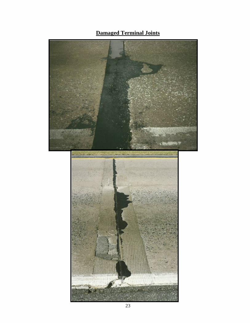
Damaged Terminal Joints Description: Terminal joints are constructed with steel I-beams imbedded in the subslabs. Terminal joints are placed at the end of a day’s paving, at a break in material delivery, etc. Typical problems are loose or missing top flanges, corner breaks in the pavement or severe spalling of the concrete at the top flange. Possible Causes: Loose and missing flanges are caused by fatigue from the repeated loading of traffic. Other problems may be caused by subgrade or subslab failures. Extent: Record the count of damaged terminal joints in the segment. There are no severity levels. Count each lane as one joint even though the terminal joint extends across all lanes in the segment.
NONE 1 2-3 >30 1 2 3TERMINAL JOINT
DAMAGED COUNT
Good Terminal Joint – Do Not Count as Damaged
23
Damaged Terminal Joints
24
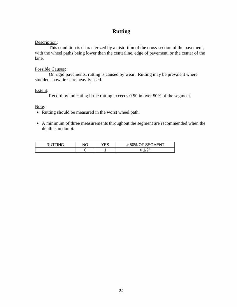
Rutting Description: This condition is characterized by a distortion of the cross-section of the pavement, with the wheel paths being lower than the centerline, edge of pavement, or the center of the lane. Possible Causes: On rigid pavements, rutting is caused by wear. Rutting may be prevalent where studded snow tires are heavily used. Extent: Record by indicating if the rutting exceeds 0.50 in over 50% of the segment. Note: • Rutting should be measured in the worst wheel path. • A minimum of three measurements throughout the segment are recommended when the
depth is in doubt.
NO YES > 50% OF SEGMENT0 1 > 1/2"
RUTTING

25
UNPAVED ROADS

26
Corrugations Description: This condition is characterized by regularly spaced waves in the road surface. They usually form on grades or in areas where the road is soft. Pothole-like depressions may also be present. Possible Causes: Slipping tires can start the development of corrugations. Minor corrugations cause the vehicle to bounce which in turn worsens the magnitude of the corrugations, thus, the condition perpetuates itself. Severity Levels: None - The road surface is smooth. Low - Corrugations are <1” deep. There is only an occasional depression, if any. Medium - Corrugations are ≥1” and ≤3” deep; depressions are ≤4” deep. High - Corrugations are >3” deep; depressions are >4” deep. Extent: Record as the percentage of the length of the segment for each severity.
NONE <10% 10-30% >30%7 8 94 5 6
0 1 2 3
CORRUGATIONS
<1" DEEP
LENGTH>3" DEEP1" - 3"

27
Corrugations - Low Severity
Corrugations – Medium Severity
Corrugations – High Severity

28
Loss of Aggregate Surface Description: This condition is characterized by the loss of surfacing material exposing rock, native stones, or other subgrade material. Possible Causes: The loss of aggregate can be caused by the action of traffic, which can breakdown or displace the aggregate, or by water erosion. Contributing to the loss of aggregate are poor crown in the roadway, snow removal and lack of dust palliative. Extent: Record as the percentage of the length of the segment that exhibits loss of aggregate surface. There are no severity levels. Note: • If there is an unpaved road with no evidence of ever having an aggregate surface, report
loss of aggregate surface.
NONE <10% 10%-30% >30%0 1 2 3
LOSS OF AGGREGATE LENGTHAGGREGATE MISSING

29
Loss of Aggregate Surface

30
Poor Drainage Description: Poor drainage is characterized by one or more of the following conditions:
- Ditches not in proper condition to direct and carry water; ditches are overgrown or filled with debris; ditches are not properly shaped.
- Inadequate cross-section holds water on the roadway; rutting from repeated
loads during soft conditions; water flowing across the road and eroding the road surface.
Possible Causes: Poor drainage is usually caused by improper shaping of the road, traffic loading during soft conditions, lack of ditch maintenance, blocked culverts and/or inadequate ditch size. Extent: Record as the percentage of the length of the segment exhibiting poor drainage. There are no severity levels.
NONE <10% 10%-30% >30%
0 1 2 3POOR DRAINAGE LENGTH
POOR DRAINAGE

31
Poor Drainage

32
Soft Areas Description: This condition is characterized by localized large ruts, depressions and ponded water in evidence. Possible Causes: Soft areas are caused by high water tables, springs at roadway level, streams flowing through the roadway or poor soil conditions. Extent: Record as counts of each occurrence of soft areas in the segment. There are no severity levels. Note: • In most cases, where soft areas are present, poor drainage will also occur.
NONE 1 - 2 3 - 6 >6
0 1 2 3 SOFT AREACOUNTSOFT AREAS

33
Soft Areas