continuous prestressed concrete box girder bridge … german construction company. a launching...
TRANSCRIPT

― ―81
SynopsisThe Nagaragawa Bridge on the Tokai-Kanjo Expressway is a 343 m long bridge crossing the Nagara River. P&Z cantilever construction method was used in this project for the purposes of enabling year-round construction for a reduced construction period and minimizing environmental impact to the river which was famous for its clear water and traditional cormorant fishing. This report describes the construction of the superstructure of the bridge using the P&Z method.
Structural DataStructure: 4-span continuous prestressed concrete box
girder bridgeBridge Length: 343 mSpan: 59.5 m + 2 × 111.0 m + 59.5 mWidth: 25.027 m − 24.575 mOwner: Ministry of Land, Infrastructure, Transport and
TourismDesigner: Nippon Engineering Consultants Co., Ltd.Contractor: P.S. Mitsubishi - Obayashi JV
Continuous Prestressed Concrete Box Girder Bridge using P&Z Method — Tokai-Kanjo Expressway Nagaragawa Bridge —
P & Z 工法による PC 4 径間連続箱桁橋の施工 ― 東海環状自動車道 長良川橋 ―
* ** ***
* Hidekatsu OKABAYASHI: P.S. Mitsubishi Construction Co., Ltd.岡林 秀勝:(株)ピーエス三菱
** Masahiro KAWASHIMA: P.S. Mitsubishi Construction Co., Ltd.川嶋 正宏:(株)ピーエス三菱
*** Tsuyoshi HASEGAWA: Ministry of Land, Infrastructure, Transport and Tourism長谷川 強:国土交通省
Contact: [email protected]: P&Z method, cantilever construction, reduction of construction periodDOI: 10.11474/JPCI.NR.2014.81
Construction Period: Mar. 2006 – Mar. 2009Location: Gifu Prefecture, Japan
1. IntroductionThe Tokai-Kanjo Expressway is a ring motorway with an extension of 160 km that links major cities located 30 to 40 km from Nagoya City and forms a wide-area expressway network in the Tokai region together with Tomei, Meishin, Chuo, Tokai-Hokuriku and other expressways.The Nagaragawa Bridge on the Tokai-Kanjo Expressway is a 343 m long bridge crossing the Nagara River which is famous for its clear water and cormorant fishing (Fig. 1). The inner (westbound) and outer (eastbound) lanes of the east-west bridge were constructed as separate single-chamber box girders and connected with each other at the upper slab and cross beams for the three of four spans (Fig. 2). The P&Z method was used in this project for the purposes of enabling year-round construction for a reduced construction period and minimizing environmental
Fig. 1 Side view of the Nagaragawa Bridge
Bridge length 343 000
Girder length 342 500
59 500 111 000 59 500111 000
P1 P2P3
P4
A1
[ Unit :mm ]
― ―82
impact to the Nagara River[1]. This report describes the construction of the superstructure of the bridge using the P&Z method.
2. Features of the P&Z MethodThe P&Z method is a prestressed concrete bridge erection system developed by Polensky & Zöllner, a German construction company. A launching gantry, or movable erection girder, is installed on the superstructure of a bridge, with two forms hanging from the gantry for segmental cantilever construction on the front and rear of a pier (Fig. 3). Many bridges have been built using this method not only in Europe but in Japan as well (Table 1). This system requires no work from the ground and has a high degree of freedom in terms of applicable span length range (50 to 120 m; Table 2). This makes the system very useful in building multi-span continuous bridges over the sea or a river or across a gorge where scaffolding cannot be built. Features of the P&Z method are summarized below.
- No restrictions from the conditions below the girder:Since no work is required from the ground, this system is applicable irrespective of the conditions below the girder such as the sea, a river, a gorge or a built-up area. Work on the column heads is also possible without using cranes or scaffolding near the pier. In this project materials supplied from the ground were carried through the launching gantry, with no additional structures built in the Nagara River, minimizing the environmental loads of the construction to the river.
- Fast construction:Construction length per segment (about 10 m) is longer than that in ordinary cantilever construction, and one segment can be completed in about 11 to 12 days. This enables faster construction and a shorter construction period. Assembly of the platform and erection girder during the substructure construction also shortened the
Table 1 Bridges built by the P&Z method
Bridge name Location Bridge length [m] (max. span)
Construction period
Tsukiyono Bridge Gunma 306.8 ( 84.5) 1981-82Tonegawa Bridge Gunma 560.0 ( 80.0) 1982-84Koshirazu Viaduct Niigata 422.5 ( 59.5) 1986-87Gassan Bridge Yamagata 474.0 (112.0) 1996-98Narusegawa Bridge Miyagi 488.9 ( 85.0) 1997-99Hamayu Bridge Shizuoka 790.0 ( 95.0) 2001-04Yoshimine Bridge Fukui 443.5 ( 50.0) 2005-07Nagaragawa Bridge Gifu 343.0 (111.0) 2006-09
Table 2 Applicable span lengths of the P&Z methodSpan (m)
*
*
* Requires temporary bents.
200 250PrecastgirdersStationaryscaffolding
0 50 100 150
MovablescaffoldingIncrementallaunchingP&ZcantileverConventionalcantilever
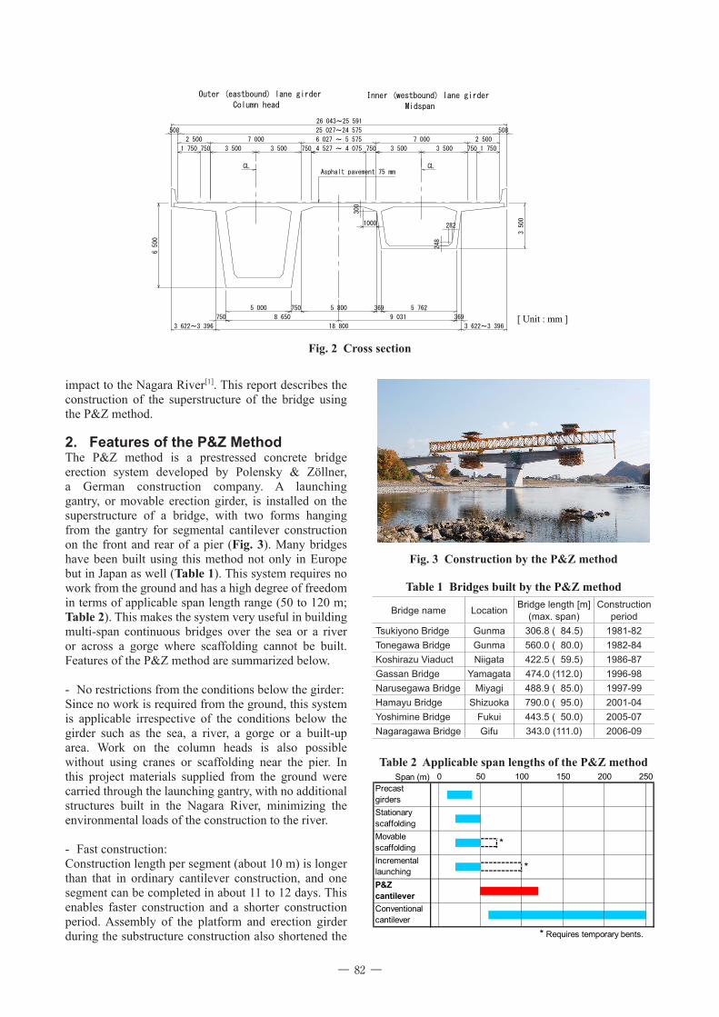
Fig. 2 Cross section
LCLCAsphalt pavement 75 mm
Column head
Outer (eastbound) lane girder Inner (westbound) lane girder
Midspan
5 800
18 800
8 650
6 500
750
750
3 622~3 396
5 000
3 500
369
3 622~3 396
369
5 762
9 031
508 25 027~24 575 508
26 043~25 591
1 750 750 3 500 3 500 750 3 500 3 500 750 1 750
2 500 7 000 6 027 ~ 5 575 7 000 2 500
4 527 ~ 4 075 750
282
248
1000
300
[ Unit : mm ]
Fig. 3 Construction by the P&Z method

― ―83
construction period.
- Labor saving mechanization:This method is mechanized with electrical equipment, achieving great saving in labor. The cyclic steps allow the operators to learn skills and improve work efficiency. Labor saving efforts in this project included mechanical and hydraulic operation of the launching gantry system and the form open-close system for clearing the piers during transfer.
- High degree of freedom in design:With segmental cantilever construction combined with movable scaffolding, this method can be applied to span lengths from 50 to 120 m and long span bridges. The same equipment can be used to build bridges
with different spans. Applications also include curved bridges and bridges with varying cross section.
- Reduced unbalanced moment:The erection girder absorbs load differential caused by asymmetric cantilever construction, preventing excessive unbalanced moment from occurring at the column head during construction. This allows making temporary fixing work smaller for construction of a continuous girder and reduces bending moment occurring in piers of a rigid frame structure.
3. ConstructionFig. 4 shows the operation steps, and Fig. 5 shows the
Fig. 4 P&Z method work steps
Cantilever construction (block-by-block segmental construction)
Span transfer of the launchinggantry to the next pier
Repeated on the innerlane girder: P3→P2→P1
Repeated on the outerlane girder: P3→P2→P1
Launching gantry disassembly
Work on the column head
Cantilever construction (block-by-block segmental construction)
Span transfer of the launchinggantry to the next pier
Returning and lateral transfer ofthe launching gantry
Launching gantry assembly
Work on the column head
Fig. 5 Schematic of the P&Z method
A1 P1 P2 P3 P4
3BL1BL 2BL 4BL 5BL3BL 1BL2BL4BL5BL 3BL1BL 2BL 4BL 5BL3BL 1BL2BL4BL5BL3BL1BL 2BL 4BL 5BL3BL 1BL2BL4BL5BL
P3→P2→P1施工方向送り桁
吊り型枠
11100011100059500 59500
Suspended forms
Direction of construction: P3 → P2 → P1
Launching gantry
Fig. 6 Launching gantry assembly
Erection girder
Steel bents
Fig. 7 Launching gantry in transfer

― ―84
概 要 東海環状自動車道は,名古屋市の周辺 30 km から 40 km 圏に位置する諸都市を連絡する環状道路であり,東
名・名神高速道路,中央自動車道,東海北陸自動車道などと一体となって東海圏の広域ネットワークを形成す
る延長約 160 km の自動車専用道路である。
長良川橋は,東海環状自動車道のうち,鵜飼いで有名な清流長良川を東西に跨ぐ,橋長 343 mの橋梁である。
本橋は,内回り線(西行き)と外回り線(東行き)を別々に 1 室箱桁として施工し,それぞれの完成後に 4 径
間のうち 3 径間部分について上床版および横桁を連結し,内回り線と外回り線を一体化する構造である。また,
本工事では通年施工による工期短縮と清流長良川への環境影響低減を目的として P&Z 工法が採用された。本
稿は,P&Z 工法による上部工の施工について報告するものである。
Fig. 8 Launching gantry shifted from left to right
Fig. 9 Single-door form opened to clear the pier
Fig. 10 Completion of the bridge
schematic of the construction by the P&Z method.The first step is assembly of the launching gantry. In this project a work platform consisting of an erection girder and steel bents was installed behind P4 for this work (Fig. 6). The completed launching gantry was moved to P3 to start cantilever construction. The launching gantry was moved from P3 to P2 and then to P1 to continue construction (Fig. 7). This bridge consists of two single-chamber box girders built in parallel and connected together using cast-in-place slabs. Therefore, when the inner lane girder was completed, the launching gantry weighing about 5000 kN was returned to P3 and shifted laterally to the position for the outer lane construction (Fig. 8). The inner and outer lane girders of this bridge share the same piers. In order to prevent interference of these piers with the hanging forms during transfer, the form open-close system was modified from the original double door type to the single door type (Fig. 9).
4. ConclusionThe advantages of the P&Z method were fully utilized in this project, with the standard cycle period (11 to 12 days) achieved by various labor saving efforts including preassembly of web reinforcing steels. The bridge was completed in March 2009, without any construction related accidents (Fig. 10). The authors hope this report would be of help for similar bridge projects in future.The authors express their appreciation to all related parties and local communities who cooperated in this project.
References[1] Hasegawa, T., Kawashima, M., Hanai, N.: Construction of Nagaragawa Bridge, Bridge and Foundation Engineering, Vol. 43, No. 7, Kensetsutosyo, Tokyo, pp. 5-11, Jul. 2009 (in Japanese)