continuous preparative gel electrophoresis t. r. c. -
TRANSCRIPT

AXALYTICAI, IJIOCHE;\USTHY 55, 492-508 (1973)
Continuous Preparative Gel Electrophoresis
T. R. C. BOYDEl AND M. A. REMTULLA"
Department of Biochemistry, iVIakerere University,Kampala, Uganda
Heceived November 2, 1973; accepted May 4, 1973
An apparatus is described for continuous electrophoresis in polyacrylamide gel. Experiments may be run for 10 days or longer. Protein loadsmay be 1 g per day or more, and there are no obvious obstacles to scalingup. A revised classification of electrophoretic processes is required.
Electrophoresis is widely used as a separative technique, particularlyin protein chemistry. In some respects gelatinous media have an advantage over others as support media for electrophoresis, perhaps mostobviously when a gel matrix of molecular dimensions is employed, allowing the simultaneous use of two properties for separation of the particlesof interest-size and surface charge density. Several devices have been
described for preparative gel electrophoresis showing that there is widespread interest in the possibility of applying this powerful analyticaltechnique on a larger scale (I-G).
The idea of continuous operation is always attractive for preparative"'ork. Continuous electrophoresis was introduced over 20 yr ago, butit has hitherto been confined to media readily permeable to water (7) orto conditions of free solution (8-14) where subtle and fascinatingapproaches have been used by many workers to prevent convective mixing. This paper describes an apparatus for continuous electrophoresis ina gel medium, not freely permeable, commencing with an account ofthe principle upon which such a device must depend, and also indicateshow this relates to other techniques in a general classification of electrophoretic processes.
Consider a strip or slab of gel which is transported continuously in adirection parallel to one of its faces. (By "face" we mean to include thenalTOW face or edge of a thin rectangular slab.) If a sample solution isapplied continuously to this face and if an electric field is applied continuously in a direction at a right angle to the direction of transport,
1 Present address: Dept. of Biochemistry, University of Hong Kong, Hong Kong.'Present address: Vancouver, B.C., Canada.
492
Copyright © 1973 by Academic Press, Inc.Al! riu;hts of reproduction in any form reserved.

CONTINUOUS PREPARATIVE GEL ELECTROPHORESIS
Point of application
493
Fmerging separated froc1ions
FIG. 1. Principlc of continuous prcparati\·c gcl elcctrophorcsis.
then the species of interest in the sample are simultaneously subjectedto two displacing influences. Firstly, and equally for all, there is thetransport of the gel slab. Secondly, there is the influence of the electricfield which will produce migration at a velocity characteristic of each·individual species. Each species will thus follow a path which is theresultant of the effect of the two influences, and, supposing that' all migrate in the same direction in an electric field, each will emerge at acharacteristic point on that face of the slab which is opposite to theface where the sample was applied, in the axis of the electric fiel4 (Fig.I)-effecting a continuous separation process. It remains to considerhow the continuously transported slab may be realised in practice andhow the emerging, separated fractions lIlay be collectecl.
Short of arranging for continuous formation of a slab of gel one canonly consider a slab wrapped round on itself to form an endless belt.In the apparatus to be described this takes the form of a vertical hollowcylinder, giving a superficial resemblance to certain devices for continuouschromatography. Indeed, there is a degree of correspondence of principle.The design of the present apparatus, however, was not approached froma knowledge of continuous chromatography and the principle is capableof realisation in forms other than that of a yertical hollow cylinder (seeDiscussion) .
The method used for collecting fractions is based on the work ofI-Ijerten, .Jerstedt and Tiselius (3). Fra.ctions emerge from the gel intoa packed bed of agarose beads in buffer solution and are aspirated continuously via a series of filters distributed evenly around the circumference of the apparatus.
One further significant point of principle is the mode of application ofsample. A simple solution disperses too readily and would not give asharp origin point; sucrose solutions were found no better in this respect.The desired physical properties arc attained by the use of a polyacrylamide solution (not cross-linked as in a gel) which is mixed with thesample solution before use. This disperses from the origin point very

494 HOYVE AND Imi\ITULLA
slowly-effectively not at all before the species of interest have migratedinto the gel-and is removed along with undesirable particulate matter,polymeric complexes, etc., once its function has been fulfilled, by acombination of scraping and aspiration.
Construction and Function of A]J]Jl1ratll,~. The core of the apparatusconsists of t\\'() matching sets of concentric cylinders-the upper andlower sections-fashioned frOln "perspex" tubing of 3-mm thickness,14.6 cm internal diameter and 12.G cm external diameter respectively
for the outer am! inner walls. Struts are placed between the outer and
inner perspex walls so as to make each part of the apparatus a rigid unit(Fig. 2). In use these are placed one abo\'e the other with circular facesin contact. Where the two sections of the apparatus meet, the perspexfaces are ground flat, allowing a watertight joint (with the aid of alittle silicone grease),
(0)
~ ~_U_Uh . h'' _
-.-------------- ..----.t
Turning bar
:on--#- Buffer Circulation
Slruts
......•.nu
----- Lugso I 2 3 4 5 ems 012345ems
(d)
FIG. 2. Construction of electrophoresis apparatus proper. (a) Upper sectionelevation. Note sensing electrodes spaced 3 cm apart in gel, accessible to a voltmeter by terminals at the upper end of the section. (b) Upper section, plan view.(c) Lower section, elevation. Arrows show circulation of buffer for mixing andcooling. (d) Lower section, plan view. Perforations in inner and outer walls areindieated in only a few compartments.
CO!\TIXUOU:-; PRfjI'ARATIVI'c GEL I<JLECTHOI'HOImSls 49,1')
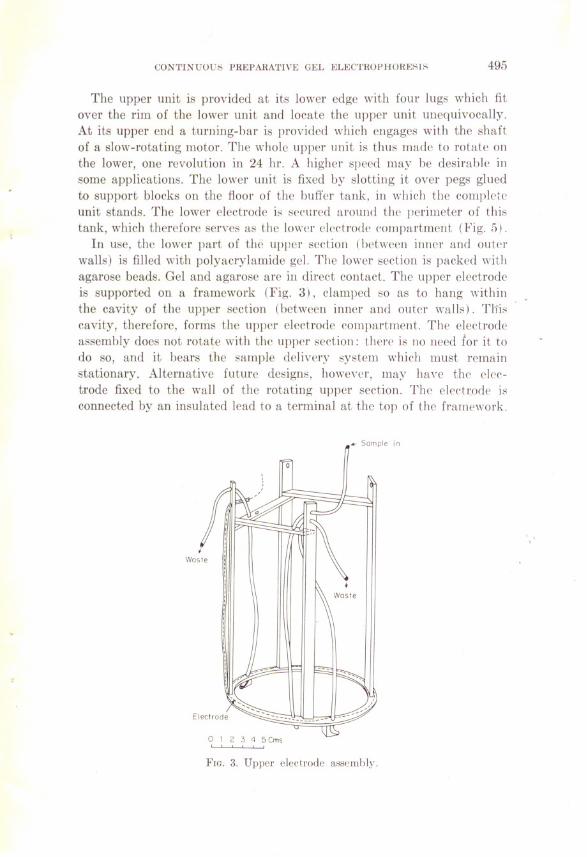
The upper unit is provided at its lower edge with four lugs which fitover the rim of the lower unit and locate the upper unit unequivocally.At its upper end a tUl'lling-bar is provided which engages with the sha Itof a slow-rotating motor. The whole upper unit is thus made to rotate onthe lower, one revolution in 24 hr. A higher speed may he desirahle insome applications. The lower unit is fixed by slotting it over pegs gluedto support blocks on the fioor of the huffer tank, in which the conlplPieunit stands. The 100ver electrode it' s('cured around the perimeter of thit'tank, which therefore serves as the lower cleetrode ('ompartment (Fig, ,'i).
In use, the lower part of the upper seetion (hct\\'een inner and outprwalls) is filled with polyacrylamide gel. The 100ver section is packed withagarose beads. Gel and agarose are in (!ired contact. The upper electrodeis supported on a framework (Fig. 3), clamped so as to hang withinthe cavity of thc upper seetion (betwecn inncr and outer \valls). Tliiscavity, thereforc, fornis the upper electrode compartment. The electrodeassembly does not rotate \vith thc upper section: then' is no need for it todo so, and it bears the sample delivery system which must remainstationary. Altel'llative future de8ign,;, hO\\·c\'('r. may ha\'c the elcr:trode fixed to the wall of the rotating upper seetion. Tlw eleetl:ode i"connected by an insulated lead to a terminal at the top of the framework .
.•... Sample in
FIG. 3. Upper electrode assembly.

496 BOYDE AND REMTULLA
Around the periphery of the lower section are a series of holes in the
outer wall, 1.25 cm in diameter, centered 2.1 cm from the top of the section.These accommodate filters consisting of porous plastic (Vyon sheet,0.1 in. (2.5 mm) thick, Porvair Ltd., Kings Lynn, Norfolk, V.K.) 0.7cm in diameter carried by perspex filter hoJders (Fig. 4). Buffer is aspirated through these, carrying in solution the separated fractions. Near thebottom arc corresponding sets of holes ill the inside and outside walls,1.25 em in diameter and centered 1.7 cm above the bottom of the
cavity of the section. Each is occluded by porous plastic sheet (Vyonsheet, as above). In the case of the outside series of holes discs of the
porous plastic arc forced in on top of pieces of dialysis membrane. Theouter series of holes serves to carry electrophoretic current, and theinside scries permits the flow of buffer to be aspirated (Fig. 4). Anyprotein which may escape past the filters migrates down to the dialysismembrane where it is arrested, probably precipitated, and certainly docslittle harm ..
The filters arc connected by flexible tubes to a Watson-Marlow "delta"
pump (Watson-l'vIarlow Ltd., Falmouth, Cornwall, V.I<.) driven by atype D/K 40 S IIlotor, giving approx 3.8 mljhr per channel with ] mmi.d. pump tubing. This rate has proved adequate but could be varied
as indicated below. In the present version, there are ]8 aspiration points,occupying ]8 of the 20 channels of our pump. From the pump, furtherflexibJe leads carry the separated fractions to collection receptacleshere boiling tubes of ]50-ml capacity in a specially made rack, packed inice, and enclosed in an insulated box. Buffer is continuously dripped intothe buffer tank to replace that lost by aspiration of fractions.
To
- Pump
o
O-ring
Agaro ••8.ad.
3 Cm.
AvaroSlSaad.
VyonSha.t
FIG. 4. Detail of lower ~eetion. Agarose beads are shown only at top and bottom,but in fact fill the entire cavity of the lower section.

CONTINUOUS PREPARATIVE GEL ELECTHOI'IIOHESIS 497
The pumping rate can be varied in discrete steps by using other tubesizes or a different type of motor. The manufacturers do not recommendthe use of more than 10 pUlllp channels with the D/l\: 40 S motor, but in
practice there has been no trouble, using the narrow pUlllp tubing. Up to50 channels can be handled by a single motor of the slower types, at amaximum pumping rate of 6 IIIl/hr per channel (using.5 mm i.d. tubing).Alternatively, and perhaps most conveniently, the pump can be drivenby a continuously variable 1II0tor (Watson-l'\[arlow MIlRE) , which alsowill handle up to 50 channels. Figures 5 and 6 provide, respectively, aschematic and an actual view of the assembled apparatus.
Buffer circulation and temperatw'e control. The upper electrode compartment is necessarily small in this apparatus, so that a brisk flow offresh buffer through this compartment is mandatory. This is convenientlydone by means of a closed-circuit system and is combined with cooling.Buffer is withdrawn from the inner buffer compartment by means of acirculating pump and forced into a heat exchanger, consisting of WolffBottle immersed in coolant. (A more efficient heat exchanger would certainly be preferred.) From the heat exchanger, buffer is returned viaa lagged pipe to the upper electrode compartment and thence to thelower electrode compartment (buffer tank) via several holes drilledround the periphery of the upper section, a little above the upper cIec-
Cold buffer from
Fixing peg
Support block
oLower electrode
Drive from Slow
rc.toti,ng motor
To heat
"- exchanger
Buffer tank
,0Lower electrode
Fw .. 5. Vcrtieal scetion of asscmbled apparatus. Arrows show buffcr eireulationfor mixing and eooling. Detail of aspiration system omitted. Lugs omittcd. Thceleetrophorcsis unit proper is raiscd on blocks above thc floor of the buffcr tank.

BOYIJI': A:\"IJ HE\I'lT LLA
•..
.,- "
!. --.-. - .•___ •• __ LIVE
1<1<:. G. G(~Il•.ral vipw of apparatus in operation. Frolll left to ri~ht.: "Chiller
•.irl'ulator." Il<'at. exdJ:1nger (in polystyrene box), bnffer circulation pump, electro
phon'sis unit. (in polystyrene box)-with power supply behind, multichannel aspira
tion pump. fraetion colleetion rack (in Pol.\·st~Tel)(, box) with. abo\'''. support I'd b~'
"laml'" till' hufiN rpseIToir and sample r•.sPIToir (lmr •.!tl').
trode. From the lower electrode ('ompartmcnt, buffer returns to the innerbuffer compartment by (·lwnneJ:.; alongside the i'uction pip(·. The heat exehanger is ("ooled uy an ethylene gIY('ol-\\'atcr mixture cireulated froma "Chiller-Circulator" (Churchill Instrument Co., Peri\'ale, .?vIiddx,U.K.). Any other conyenient, refrigeration deyi('(' may be employed and,in the event of mechanical breakdown, the tank may be filled with ice.
Heat exchanger, electrophoresis apparatus proper, and fraction collection rack arc all lagged with expanded polyst~Tene, allmving operationat normal ambient temperatures. \Ve would like to \\'ork at Jower buffertemperatures than to date. chiefly because of eyidl'nce that swellingof acrylamide gel can be held to an l'xtremely low 1l'\'(~1at 0-4°C (Boyde,unpuhlished). This might be achieycd by working a ('old room (which"'ould also a\'oid difficulties oyer keeping the sample res('l"yoir cold), butthe practical difficulties and the incrl'ased risk of ell'ctric shock argueagainst. this.
Packing agal'Ose-bead bed. The electrophoJ'{'sis unit. lesi' uppf'r electrode, is established in the buffer tank, on a IPn'l surface. and waterpoured in up to the leyel of the top of thf' lower section. The jointbetween the upper and the Im\'er section", should ha\'e been lightly andevenly greasf'd. The agarose beads used to date haye been Sepharose 213

COXTI:q;oc:; I'HEI'ARATln: (;EL ELECTROI'HORE:;I~
(Pharmacia). The suspension is diluted by adding one-tenth \'olumc ofwater and 250 ml is poured into the eayity between the \ntlb of thecylinder. The leye\ comes aboye the top of the lower section, but wateris lost through the porous plastic. After allowing a little time forsettlement, \\'ater is withdrawn from the buffer tank, little by little,until the layer of a~arose is flush with the top of the lower sedion. The
upper section is then \'Cry carefully remoyed.Casting gel for electrophores~~. An ancillary piece of apparatus is re
quired here-a raiscd ring or solid cylinder with a flat upper smface andof dimensions suitable to occlude the 100\'er end of the intenndl cayity
of the upper seetion, without interfering with the dowl1\\'ard-projectinglugs. The occluding ring is placed on a flat surface, its upper surfacecovered with a greased rublwr gasket and the upper section placed inposition on top of this, lightly weighted to hold it in place. The gelcasting solution is made up as follows:
Acrylamide 9.5 g. N,.V' -methylcne bis acrylamide 0.5 g (hoth fromKoch-Light Laboratories, Colnbrook, Bucks., U.K.) and ammonium persulphate 200 mg (Analar, BDII Ltd., Poole, Dorset, U.K.) arc dissol\'Cdin \\'ater to a final yolume of 200 ml. To this is added 0.2 ml .V,X,N',X'tetraethylenediamine (BD J-I, Poole, Dorset, U.K). After mixing, thesolution is carefully poured into the inter-\\'all ca\'ity of the uppersection, and left to set for 1 hr. This gins a gel of height ;j cm. Thevolume of gel casting solution can rpadil~' be yaried to give {!;els ofdifferent heights. The 100\'er limit is :::et hy the nece:::sit~· to co\'Cr thetops of the struts. The upper limit is normally set by the IHltTer-circulation holes, though these can be oceluded with bung::: and a hi{!;her :::eriesof holes employed. Gel strength and compo:::ition can abo 1)(' easily \·aried.It is not necessary to exclude air from the pol~'merising gel. Pro\'idedambient temperature is high enough and the apparatus accuratelylevelled the procedure de:::cribed gins reproducihly a strong gel with asmooth, level. upper smface.
Assembly and pre-rlill. The pre-run selTes several funC'tion:::-to remove('atalyst molecules from tll!' gpl. to introduce the plpctrophorcsi,.: buffer tothe gel. to bring the \\'hole :':~'stem to the condition of temperature, electricfield, huffer flO\\', dc .. \\'hich wi]] he u:::ed in the ('xpprin1t'nt and to test.out a]] systems hefore risking any sample.
The upper "'l,(·tion. ('olllplete \\'ith gel, is gently freed fron} its castinghase, the lower perspex edges lightly greased (Silicone compound .:\'1.8. 4has been used. This is prepared for l\I.8.E. Ltd. by Robert Blackie Ltd ..London 8.E. 14, FK. Other silicone greases may "'ell he suitahle). Theseet.ion is then put in place on thp 10\\'PI' seetion and twisted to and fro tocnslln' a good ,.:cal and to :::pl'ead tll!' grca,.:e ('v{'nl~·. It has ]H'{'II found 11":('-

500 BOYDE AND REMTULLA
ful to suspend weights of about 500 g from the turning bar to reduce therisk of the upper section becoming detached. Distilled water and bufferconcentrate are now added to bring the level of the selected buffer up to ]cm from the top of the buffer tank. The upper electrode assembly is lowered into place and clamped, taking care that it does not interfere with theturning of the upper section. The drive motor is brought down to engagewith the turning bar, and clamped into place, making sure that the driveis correctly centered (otherwise the turning of the upper section willbe jerky, or it may even become completely detached). The buffer delivery pipe is clamped so as to deliver into the upper electrode chamber.After making electrical connections, all systems are set going-refrigeration unit, buffer circulation pump, electrophoresis power supply, slowrotating motor, multichannel pump, and buffer replenishment supply.Temperature and voltage settings should be those to be used in the actualexperiment.
"Tith a pre-run done in this manner, the unwanted catalysts from'thegel are only diluted, not completely removed. It would doubtless bepossible to remove them by dialysis through the upper electrode chamber,
or by providing for a different system of buffer flows during the pre-r~m.The total buffer capacity of our system is over 8 liters, however, so thatthe catalyst molecules are diluted 40-fold-probably sufficient to preventthem from being a nuisance.
The pre-run is normally continued overnight to ensure achievement ofsta ble conditions.
Preparation and application of sample. A polyacrylamide solution isprepared as follows: 20 g acrylamide, and 200 mg ammonium persulphateare dissolved in water to a final volume of 200 ml. To this is added 0.2 ml
N,N,N',N',-tetraethylethylenediamine, and after mixing the whole ispoured into a ]-Iiter beaker and left] hr to set. The catalysts are nowremoved by dialysis. The beaker is filled with water, left for] hr, thenthe water poured off and the beaker refilled. This is done three times in
all. The solution may be kept indefinitely. It has proved difficult toproduce polyacrylamide solution of consistent viscosity: we are not surewhy; possibly this is a matter of variation between different batches
of reagents. Fortunately, the system can tolerate considerable varia
tion in viscosity-flow rate is readily controlled. As a rough guide, thepolyacrylamide solution should be such that if fjO ml is placed in a100-ml measuring cylinder and this is inverted, it reaches the orificein about 30 sec. Recently, we have used the dialysed 10% polyacrylamidedirectly. Formerly it was necessary to dilute the solution by stirring inan equal volume of water-a tedious job; the introduction of bubbles mustbe kept to a minimum as they are lost very slowly.
A predetermined amount of the polyacrylamide solution is weighed out

COXTIXUOUS PREI'AllA'I'IVE GEL ELECTHOPHORE~IS 501
into a stoppered cylinder and to this is added an equal volume of thesample, prepared as a protein solution of 5%. The two are mixed by verygentle inversion only. Air bubbles are fatal unless very few in number:they are easy to introduce and difficult to remove (though high-speedcentrifugation might do it). The mixing process takes about 30 min. Amechanical device would no doubt be useful for this job.
The sample reservoir consists at present of a hurette, attached to alength of 2 mm i.d. flexible tubing. Rate of sample flow is controlled byraising or lowering the reservoir. It is very convenient to lw able tomonitor rate of sample flow by the burette-but a tap-funnel suspendedfrom a spring balance might be better.
The prepared sample solution is poured into the reservoir (burette) - .again a task requiring patience-and allowed to run down the flexilJlesample delivery tube to its end before the tube is placed in position. Todo this, the electrophoretic current must be switched off and the upperelectrode assembly raised so that the tube may be threaded through itsguide holes (Fig. 3). The electrode assembly is then again lowered intoposition, and clamped so that the top of the sample delivery tube is about1.0 mm above the surface of the gel. When sample flow is switched on,the viscous solution should flow out forming a mound 1-2 cm in lengthwithin a few minutes. Flow rates of up to at least 2.0 I11l/hr have beenfound satisfactory.
The exhausted polyacrylamide solution (free of sample) is scrapedup from the upper surface of the separative gel by means of "shoes"attached to the upper electrode assembly, and aspirated via the multichannel pump-occupying the remaining two channels. Two shoes areused, placed to scrape up polyacrylamide 6 and 22 hr after the application of sample (Fig. 3). It is not yet possible to say whether this givesimproved results.
EXPERIMENTAL
We present here the results of one particular run, in which two completely different separations were attempted-first bovine serum albuminand human hemoglobin, over a period of 48 hr, then, after a brief interval,the oligomeric forms of horse spleen ferritin, again over a period of 48 hr.Following this, the run was kept going without sample for 9 days (total15 days) and the condition of the electrophoresis gel examined at the endof that period. The results obtained on this occasion are representative.
For run A, the sample was prepared as follows: human bank bloodwas centrifuged and the packed red cells washed three times by resuspending in 1.2% sodium chloride and again centrifuging. The resultingwashed red cells were hemolysed by resuspending in 4 volumes of distilledwater and this solution cleared by centrifugation at 100,000g (MSE

502 BOYDE AXD HE;\ITLLLA
5550, rotor .No. 59113, 30,000 rpm for 2 hr). The hemoglobin concentrationwas measured by diluting and mca~urin!!; the absorlmnce of the solutionat 540 nm and was found to be 7.34 g/100 m!. This solution was mixedin equal parts with a 5% solutiou of bovine serum albumin, obtainedby dilution of a 30% solution (as supplied fOl' imnllmolo!!;ical testing byPoviet Producten, N.V., Amsterdam, Netherlands). Of the resulting solution (3.670/0 hemoglobin, 2.lj% albumin), 22 ml was mixed with 31 gdialysed 101"0 polyacrylamide.
For Run H, 10%) horse spleen ferritill, as supplied by Koch-Light Laboratories Ltd. (Coin brook, Bucks, U.K.) \\'as diluted to 4% and of thissolution 20 ml was mixed with 21.4 g dialysed 10% polyacrylamide. Regrettably, the ferritin solution was not centrifuged before use.
Details of the electrophoresis cOllditioll~ arc given in the legend toFig. 7. Hun A shows good separation of hemoglobill and albumin. ThGreis some "overlap," but this may be due in part to heterogelH'ity of thehemoglobin. Hemoglobin was estimated in eluteri fractions by determiningabsorbance at 540 nm, and albumin by absorbance at 280 nm-corn~ctedfor the hemoglobin content. A"80 due to hemoglobin was taken as A540 X0.282. Albumin was taken a~ A",o (corrected for hemoglobin) X 140(mg/lOO m]). Because of the means used to estimate albumin, theappearance of "albumin" in fractions 7-12 may he due to experimentalerror either in th is experimen t, or in the factors used for ca I('ilia tions.
Qualitative electrophoresis of the separated fractions confirms the goodseparation achieved (Fig. 8). There is evidence of heterogeneity withinthe main hemoglobin band, but it has not been possibl(~ to pursue thisfurther in respect of the particular blood donor concerned. Hecovery figures, based on collections A 2 and A 3 and on the average sample flowrate, were albumin 83%, hemoglobin 7F>%.
Run I3 sho\\'s clear separation of the monomeric felTitin. Ferritin con
tent of separated fractions was estimated by absorbance at 280 nm
chosen for sensitivity, but perhaps ulJ\\"isely sinee the apoferritin alwayspresent in ferritin preparations also absorbs at this wavelength. Itselectrophoretic mobility differs slightly from that of fClTitin, so that the
results may be slightly blurred. Ferritin dimer docs not appear clearlyin B 1, not having had time yet to emerge, but is clearly shown in B 2and 13 3 in fractions 12-16. Trimer was not rietected on this occasion.
The identifications given above were confirmed by f]ualitati\'C electrophoresis (Fig. 9), which shows also that a small amount 01fmonomer is
present in fractions 12-16. Figure 7 shows 280-nm absorbing materialpresent in all fractions, which is \'Cry probably ferritin monomer and
may have appeared either because of escape of ferritin past the aspirationpoints or because of elution of monomer from ferritin aggregates deposited

CON'l'lNUOUS I'HEI'ARA'l'l\'E GEL ELECTHOI'HORESIS 503
20
20
AI • AlbII
BI • Ferritin" Hb
o Volumefraction
I100500
z2>-u
100
<!II:Ie..J'"50
"-zw>-0aII:
A3II B3 IQ.
'"200 '"
150100500
1015IB 0 5101518
Fraction number
FIG. 7. The graphs shol\' total protein content of individual fractions determinedas stated in th(~ text. (But for run B divide figure~ from graph hy 10.)
For Run A conditions were as follows: 50 m:,[ sodium borate buffer pH 8.4.Potential applied-IOO V (anode end down), giving approximately 140 mA and agradient of 5 VIcm on the gel itself. Temperature of buffer flowing into upperelectrode compartment 6.7-8.5°C. Temperature of outer electrode compartment6.&-8.5°C. Sample applied at about 45 cm head, giving a flow rate of 0.43 mljhr.Collections made as follows: AI, 21 hr; A2, 30 hr; A3, 44 hr, after applying sample.
For Run 13 conditions were as follows: 50 m:'l sodium borate buffer pH 8.1.Potential applied 140 V, giving approx. 230 m1\ and a gradient of 7 V/cm on thegel. Temperature of upper electrode compartment 8.&-11°C. Sample applied atapprox 60 cm head, giving a flow rate of 0.20 mljhr. Collections as follows: 131,20 hr; B2, 28 hr; 133. 42 hr after applying sample.
The run continued for a further 9 days under the same electrophoresis conditions.At the end of this time, the gel temperature was 14.3°C-presumably it had beennear this temperature throughout both runs.
Fraction 1 is that collected from the elution point immediately below the sampleapplication point; remaining fraction numbers count round in sequence in thedirection of rotation.
Elution point 15 yielded nothing throughout the experiment (blocked filter).The other elution points \I'orked well to begin \I'ith, but Nos. 9 and 10 began tofail during Hun 13-presumably due to partial blocking of the filters. This rim wascarried out with an early design of aspiration filter of smaller area and more liableto blockage than the presen I, design.

504
I•,I30YDE AND REMTULLA
••
• ,•
FIG. 8. Results of run AI. Qualitative electrophoresis of eluted fractions, coneentrated by dialysis against Aquacide (Calbiochem). From left to right: bovineserum albumin-hemoglobin mixture (BSA/Hb), fractions 3-5 (showing appearanceof albumin dimer), 6-9, BSA/Hb. Electrophoresis in polyacrylamide slab, andstaining for protein, as described earlier (17,18).
I ••
FIG. 9. Results of run B2. Methods as for Fig. 8. From left to righ t: originalferritin, fractions 1, 2, 6-8, 12-14.

COXTIXUOUS PHEPAHATIVE GEL ELECTHOPHOHESIS 505
all round the top of the separative gel. Heeovery, calculated as for run A,was 92%.
At the end of Hun 13, the separative gel was stained brown all around.This is attributed to the presence of aggregates, as indicated immediatelyabove, and could presumably be eliminated by preliminary high-speedcentrifugation.
At the end of Hun 13, the separative ge] was not appreciably swollen,but the electrophoresis was continued for a further 9 days (withoutsample) and, at the end of this time, there was marked swelling of thetop (cathode end) of the gel, although not to the point of fragmentation.There is reason to suppose that the use of lower temperatures would delaythe onset of serious swelling even further.
DISCUSSION
Electrophoretic experiments may be e]assified primarily according towhether they arc of "microseopic," "boundary" or "zone" type 'and thenaccording to whether they are eondueted in free solution or in a supportingmedium. Preparative processes arc neeessarily of the zone type, and maybe further subdivided a<:cording to whether they are discontinuous (1
stage, with automatic elution; or 2-stage, in whieh elution of fractionsis a separate operation) or whether they are continuous in operation. Asindicated above, apparatus for continuous preparative electrophoresisis available both for free-solution and for supporting media, but until nowhas not been available for use with media which also permit molecularsieving effects. An additional entry must, therefore, be made in theclassification given earlier (6) (see Table 1). It should, perhaps, beemphasized here that the definition adopted of the term electrophoresisis that given earlier (6)-"rneasurements or separations based specifically
on migration velocity in an electric field"-and thus excludes techniqueswhich employ similar apparatus but s]ightly different principles (iso-'eleetric focusing, isotachophoresis) or addition a] physical principles (e.g.,electrodeeantation, field-flow cataphoresis, etc.), but includes e]ectrophoretic separation techniques in which the supporting medium playsa significant part.
The endless belt of separative gel need not take a cylindrical form.The present form of apparatus may be likened to the Edison "Phono
graph": it is also possible to build an apparatus analogous to the "Gramophone." Here a rotating hollow-centered disc of ge] makes wiping contact with other (stationary) discs lying in the same horizontal planeinside and outside the rotating disc. A t the inner and outer limits, respectively, of the stationary gel discs are collection chambers separated from
each other by radial walls and limited on their "e]ectrode" side bysheets of dialysis membrane. At the eentre and at the periphery of the

506 BOYDE AND R~;;\[TULLA
TABLE IClassification of Electrophoretic Proce~~e~ (I:eference Numhers)"
~
Supporting mediumFree
No molecularMolecularType
slevlJlgSICVlJlg
;\!icroscopic(analytical)
111
Boundary(analytical)
2021
Analytical
222:~
24
Two-stage
.-
25'"
.~ 262728
~ 2"
QJSingle-stage 2!J1
"°b(a) flow elution
50: c; ...
0:~ lSingle-stage 2(3 ~ (b) intermittent 6
elutionContinuous
S, \17This paper
"Note: (i) References given are exemplary only find do not necessarily indicate eitherpriority of principle or the best available tedlllique. (ii) Gel tedll1iques occur in boththe middle column and the last. (iii) ;\!any techniques ('ould be applied to supportingmedia other than those for which first described.
apparatus would be the electrode compartments. This alternative designmay well prove superior for small-scale work. Sample would be introduced continuously into a circular groove in the rotating disc. :Meanswould be required to prevent electrodecantation: quite possibly the viscouspolyacrylamide solution used in the present work would be suitable forthis purpose also. The major advantage of this arrangement would Iwthe possibility of collection of species migrating in both directions fromthe origin slot. For the use of the present apparatus it is essential thatall the significant species should migrate ilj the same direction (downwards). One can conceive of arrangements permitting double-endedoperation with the vertical cylinder COD figuration, but none seem likelyto be really practicable. Still other geometrical arrangements of the endless belt are conceivable, but perhaps less likely to be of service.
Several other recently described electrophoresis devices are cylindrical

CON'rIXUOUS I'REI'AHATIVE (;EL ~JLECTHOPHORESI" .'j07
in form with an annular separative chamber. There, however, the resemblance ends. The apparatus of .Jovin, Chrambach, and Naughton (5), andothers apparently based upon it, are for single-stage discontinuous preparative gel electrophoresis. The hollow cylindrical form is adopted for convenience and to assist in providing symmetrical cooling. The cylinderdocs not rotate in these designs, nor docs it in the apparatus of Ferris et at.(1.1) which is for analyt ical electrophoresis of multiple samples. In otherapparatuses (10,11,13,14), rotation of the cylindrical electrophoresisbed plays an important role, but is essentially for stabilisation in asystem for free-solution preparative electrophoresis. Similarly with theapparatus of Hjerten (J 6), in which the chamber, though cylindrical, isnot annular.
There remain some difficulties with the present apparatus. \Ve observerepeatedly that the elution points of some particular protein may. varyas much as ±0.5 aspiration point during the course of a run (i.e., ± J00
of ai'c). The most plausible explanation we can assign to this phenomenonis variation in the electrophoretic field strength with time. We have been
obliged to use rather crude equipment for pl"Oviding the electrophoreticpotential-without true voltage or CUITent stabilisation-but even so the
degree of variation is "urpri"ingly large. The problem may be eliminatedwhrn \ve can use a stabilised power supply of sufficient capacity, particularly if this is controlled from remote sensing electrodes. Spatial variation of the electric field should be less serious, since it should not causethe elution point to change from time to time.
Slo,,'-moving species may be carried around through more than onerevolution, and thus be eluted along with faster migrating material. In thefinal analysis, this is a weakness inherent in the use of an endless belt:
it may be minimised by choosing appropriate conditions for a particularassay and in general by the use of a longer "belt." For a machine resem
bling the present one, this would mean using a much larger diametercylinder. Its linear circumferential rate of mo\"Cment would be similar
to what is used now, hut its angular velocity would be correspondinglyless. There would be many more aspiration points, arranged at linearintervals similar to "'hat is used at present. The alternative of usingmuch higher electric fields and therefore higher migration velocities, maybe impractical because of the requirement to keep the acrylamide gelcold. We cannot emphasize too much that the gel itself must be at less
than] 00 if swelling is not to become a problem over a period which maybe 30 days or more. Probably, even lower temperaturps would headvantageous.
Other authors have had trouhle with s\velling of polyacrylamide gelsused for preparativp electrophoresis. Our experience so far suggests that
508 BOYIJE AND RE;\!TULLA
this is chiefly because the actual temperature of their gels was greater thanthey supposed, that is, they were using too high a current for their conditions, though buffers vary considerably in their potentiality for causingswelling.
Scaling up would be necessary to bring the apparatus into the truecommercial range. A modest increase in scale should be possible withapparatus very like the present one and an increase in capacity by 10-100fold might be possible using the principle of face cooling (6). The limiting factor, if polyacrylamide gel is to be used, is in holding the gel temperature low enough, in the center of the slab, to prevent serious swelling.The apparatus, or a similar one, may find uses with other types of supportmedium.
REFERENCES
1. MURRAY, IC (1962) Anal. Biochem. 3, 415.2. SClIENKEIN, 1., LEVY, M., AND WI,IS, P. (1968) Anal. Biochem. 25, 387.3. HJERTEN, S., .TERSTEDT,S., AND TISELlUS, A. (1969) Anal. Biochem. 27, 108.4. GORDON, A. n., AND LOUIS, L. N. (1967) Anal. Biochem. 21, 190..5. JOVIN, T., CIIRA;\IBACH, A., AND NAUGHTON, M. A. (1964) Anal. Biochem. 9, '351.6. BOYDE, T. R. C. (1971) Occasional Paper No. I from the Dept. of Biochemistry,
Makerere University, Kampala.
7. GRASSMANN, W., AND HANNIG, K. (1949) German Pat. No. 805,399.8. l'I!ILPOT, .T. ST. L. (1940) Trans. Faraday Soc. 36, 38.9. BARoLI,lIm, .T., WATZKE, E., AND GIBIAN, n. (1958) Z. Naturforsch. 13b, 754.
10. KOLIN, A. (1960) Proc. Nat. Acad. Sci. U.S.A. 46, 509.11. KOLIN, A. (1964) Proc. Nat. Acad. Sci. U.S.A. 51, 1110.12. KOLIN, A., AND Cox, P. (1964) Proc. Nat. Acad. Sci. U.S.A. 52, 19.13. KOLIN, A., AND LUNER, S . .T. (1969) Anal. Biochem. 30, 111.14. PHILPOT, .T. ST. L. (1970) Brit. Pat. No. 1,186,184.15. FERRIS, T. G., BUDD, R. E., EASTERLING, R. E., AND WRIGIIT, W. J. (1970) U.S.A.
Pat. No. 3,499,833.16. HJERTEN, S. (1958) Ark. Kemi 13, 151.17. BOYDE, T. R. C. (1968) Z. Klin. Chem. 6, 431.18. BOYDE, T. R. C. (1969) Biochem. J. 111, 59.19. ELI,IS, R. (1912) Z. Phys. Chem. 78, 321.20. TISELIUS, A. (1937) Trans. Faraday Soc. 33, 524.21. LODGE, O. (1886) Report of British Association for the Advancement of Science.
Birmingham, p. 389.
22. DURRUM, E. L. (1950) J. Amer. Chem. Soc. 72, 2943.23. S;\[ITHIES, O. (1955) Nature 175, 307.
24. RAYMOND, S., AND WEINTRAUB, L. (1959) Science 130, 711.25. SVENSSON, H. (1948) Advan. Protein Chem. 4, 251.26. SVENSSON, H., AND VALMET, E. (1955) Sci. Tools 2, 11.27. KUNKEL, H. G., AND SLATER, R..T. (1952) Proc. Soc. Exp. Bioi. Med. 80, 42.28. RAYMOND, S. (1964) Science 146, 406.
29. PORATH, J., LINDNER, E. B., AND JERSTEDT, S. (1958) Nature 182, 744.