continuous modulation of electrode work function with mixed self-assembled monolayers and its effect...
TRANSCRIPT

pubs.acs.org/Langmuir
Continuous Modulation of Electrode Work Function with Mixed
Self-Assembled Monolayers and Its Effect in Charge Injection
Kun-Yang Wu, Szu-Yen Yu, and Yu-Tai Tao*
Institute of Chemistry, Academia Sinica Taipei Taiwan, Republic of China 115
Received January 6, 2009. Revised Manuscript Received March 5, 2009
Self-assembled monolayers (SAMs) of binary mixtures of n-decanethiol and the fluorinated analogue(3,3,4,4,5,5,6,6,7,7,8,8,9,9,10,10,10-heptadecafluoro-1-decanethiol) were formed on silver surface. The film structurewas characterized by reflection absorption IR andXPS to be a homogeneousmixture of the two components. Themixedmonolayers serve to tune the work function of silver over a wide range by varying the surface composition of the mixedmonolayer from 4.1 to 5.8 eV. The mixed SAM-modified Ag surfaces were used as the anode in the fabrication ofhole-only devices with the device structure Ag/SAM/HTL/Ag, where HTL represents a hole-transporting layer. It isshown that depending on the HTL used and thus the HOMO level involved, the maximum current injection into thedevice occurred with differently modified Ag. Top-emitting organic light-emitting diodes fabricated with differentlymodified silver electrodes showed that the maximum current and maximum luminance efficiency occur at anodesof different modifications due to a change in the hole-electron charge balance.
Introduction
Charge injection at the interface between a metal electrode andan organic semiconductor material is involved in a variety oforganic electronic devices, including organic light-emitting diodes(OLEDs), organic field-effect transistors (OFETs), organicphotovoltaics, etc. A Schottky barrier is present at the metal/organic interface due to different energy level alignments of themetal work function and the highest occupied molecular orbital(HOMO) or the lowest unoccupiedmolecular orbital (LUMO) ofthe organic molecule, depending on the type of charges to beinjected. Reducing the barrier between the electrode and organiclayer is in general desirable for efficient charge injection.1
To reduce the barrier for charge injection from the metalelectrode to the organics, one can use an organic material withproper HOMO (or LUMO) level by judicious choice of theorganic materials or by structural modification of the materialthat has been demonstrated to be promising. These approacheswould nevertheless introduce other variables such as differentcharge mobility for the new material or change in another inter-face involved in amultilayereddevice structure.Alternatively, onecan use metal electrodes of different work function. This ap-proach would be limited by the adequacy of the particular metalin terms of conductivity, stability, or transparency/reflectivity ofthe metal involved. Furthermore, one can modulate the workfunction of a metal by surface treatment/modification.2 The sizeand direction of the interface dipole introduced by the modifica-tion are suggested to effect the modulation.3 Among variousmodifications, the use of a self-assembled monolayer (SAM)grafted on ametal surface has been shown to have great potential
for systematic modulation of the work function through struc-tural change of the molecule used. Thus, by utilizing mercaptan-based SAMs, the energy barrier for the hole injection from theAg(or Au) anode to an organic layer could be varied.4 Besidesintroducing an oriented dipole, the SAMalso imposes a tunnelingbarrier through which the charges have to pass to reach theorganic layer. The current response as a function of the tunnelingbarrier, which can be modulated by the chain length of theSAM-forming molecules, provides insight to the charge balancesituation in the device. We recently reported the use of SAMsof various organothiols on Ag for the fabrication of efficient top-emitting OLEDs. The hole injection efficiency, electrolumines-cence (EL) property, and device performance depend profoundlyon the monolayer used.5
Mixed monolayer can be prepared either by exposing a sub-strate to a solution containing more than one component or byligand exchange fromapreformed single-componentmonolayer.6
The distribution of the two components in the mixed monolayercan be phase-separated or homogeneously mixed, depending onthe functional group or chain length of the molecule involvedor the method of preparation.7 The mixed monolayer providesa versatile approach to alter the surface property over a widerange systematically. For example, the wetting characteristicshave been shown to be tunable by mixed monolayers containinga hydrophobic and a hydrophilic constituent.6
*Author to whom correspondence should be addressed (e-mail [email protected]).(1) (a) Ishii, H.; Sugiyama, K.; Ito, E.; Seki, K. Adv. Mater. 1999, 11, 972–972.
(b) Ishii, H.; Hayashi, N.; Ito, E.; Washizu, Y.; Sugi, K.; Kimura, Y.; Niwano, M.;Ouchi, Y.; Seki, K. Phys. Status Solidi a-Appl. Res. 2004, 201, 1075–1094.(2) (a) Lee, J. Y. Appl. Phys. Lett. 2006, 88, 073512. (b) Hong, K.; Lee, J. W.;
Yang, S. Y.; Shin, K.; Jeon, H.; Kim, S. H.; Yang, C.; Park, C. E. Org. Electron.2008, 9, 21–29. (c) Chen, C.W.; Hsieh, P. Y.; Chiang, H.H.; Lin, C. L.;Wu, H.M.;Wu, C. C. Appl. Phys. Lett. 2003, 83, 5127–5129. (e) Ganzorig, C.; Kwak, K. J.;Yagi, K.; Fujihira, M. Appl. Phys. Lett. 2001, 79, 272–274.(3) Crispin, X.; Geskin, V.; Crispin, A.; Cornil, J.; Lazzaroni, R.; Salaneck, W.
R.; Bredas, J. L. J. Am. Chem. Soc. 2002, 124, 8131–8141.
(4) (a) Campbell, I. H.; Rubin, S.; Zawodzinski, T. A.; Kress, J. D.; Martin, R.L.; Smith, D. L. Phys. Rev. B 1996, 54, 14321–14324. (b) Campbell, I. H.; Kress, J.D.; Martin, R. L.; Smith, D. L.; Barashkov, N. N.; Ferraris, J. P. Appl. Phys. Lett.1997, 71, 3528–3530. (c) Zehner, R. W.; Parsons, B. F.; Hsung, R. P.; Sita, L. R.Langmuir 1999, 15, 1121–1127.
(5) (a) Hung, M. C.; Wu, K. Y.; Tao, Y. T.; Huang, H. W. Appl. Phys. Lett.2006, 89, 203106. (b) Wu, K. Y.; Tao, Y. T.; Huang, H. W. Appl. Phys. Lett. 2007,90, 241104.
(6) (a) Folkers, J. P.; Laibinis, P. E.; Whitesides, G. M.; Deutch, J. J. Phys.Chem. 1994, 98, 563–571. (b) Chen, S. F.; Li, L. Y.; Boozer, C. L.; Jiang, S. Y.Langmuir 2000, 16, 9287–9293.
(7) (a) Takiue, T.; Matsuo, T.; Ikeda, N.; Motomura, K.; Aratono, M. J. Phys.Chem. B 1998, 102, 5840–5844. (b) Chen, S. F.; Li, L. Y.; Boozer, C. L.; Jiang, S. Y.J. Phys. Chem. B 2001, 105, 2975–2980. (c) Tielens, F.; Costa, D.; Humblot, V.;Pradier, C. M. J. Phys. Chem. C 2008, 112, 182–190. (d) Lussem, B.; Muller-Meskamp, L.; Karthauser, S.; Waser, R.; Homberger, M.; Simon, U. Langmuir2006, 22, 3021–3027. (e) Stranick, S. J.; Parikh, A. N.; Tao, Y. T.; Allara, D. L.;Weiss, P. S. J. Phys. Chem. 1994, 98, 7636–7646.
Published on Web 4/6/2009
© 2009 American Chemical Society
DOI: 10.1021/la900046b Langmuir 2009, 25(11),6232–62386232
In this paper we describe the formation and structure ofmixed monolayers from an n-alkanethiol (n-decanethiol, HDT)and its fluorinated analogue (3,3,4,4,5,5,6,6,7,7,8,8,9,9,10,10,10-heptadecafluoro-1-decanethiol, FDT) on silver surface. Thesemixed monolayers were used to tune the work function of theunderlying silver metal. The n-decanethiol is known to decreasethe work function, and the fluorinated thiol serves to increasethe work function.4,8 The mixtures of the two allow continuoustuning of the work function simply by varying the composition inthe monolayer. A wide range of work function can be achieved(4.1-5.8 eV). These modified substrates can be used as theelectrode in the fabrication of organic electronic devices withvariable charge injection barriers. Hole-only devices were preparedwith several hole-transportingmaterials to show that depending onthe HOMO of the organic material involved, different modifica-tions were needed to reach the maximum current injection.The ability to tune the injection barrier for hole charges allowsus to examine the hole/electron charge balance in an organiclight-emitting device, which is crucial to the device efficiency.
Experimental Section
Materials. HDT and FDT were purchased from Aldrich(Figure 1). Silver (99.99%) were obtained from ELECMAT.
Preparation of Monolayer. The silver substrates were pre-pared by thermally evaporating 150 nm of silver on a 2-in. siliconwafer or microscopic slides. The silver substrates were immersedin a 1 mM ethanolic solution of thiol mixtures consisting of HDTand FDT in different mole ratios (1:0, 4:1, 2:1, 1:1, 1:2, 1:4, 0:1)for 2 h. The substrates were then removed from the solution,rinsed with absolute ethanol and acetone, and finally dried witha nitrogen flow before characterization and/or device fabrication.
Characterization. Reflection-absorption IR spectra weretaken with a Bio-Rad FTS-60 infrared spectrometer equippedwith a DTGS detector. A custom-designed optics unit withan 86� incidence angle and p-polarized light were employed.Plasma-cleaned gold was used as reference for all spectra.XPS data were taken with an Omicron ESCA /Scanning AugerSystem with a chamber vacuum of 1 � 10-10 Torr. The workfunction of the modified surface was measured with a photo-electron spectrometer (AC-2, Riken Keiki) in ambient condi-tions with a UV source.9
Device Fabrication. The Ag electrodes were prepared bythermally evaporating 150 nm of silver layer on a soda glass, withthe area (0.4 mm2) defined by a patterned shadow mask. The Agelectrodes were then immersed in 1 mM ethanolic solution ofbinarymixtures of thiols for 2 h. ThemodifiedAg substrates wereplaced in a custom-designed rotating sample holder in a vacuumchamber (5 � 10-6 Torr) for the device fabrication. Variousorganic layers were deposited, followed by electrode depositionwithout breaking the vacuum. The thickness was controlled by aquartz thickness monitor. After the evaporation processes, thedevices were encapsulated with a cover glass using UV-curedepoxy glue. The current density-voltage (J-V) characteristicsof the devices were measured by a computer-controlled Keithly2400 Source meter connected with a spectrophotometer PR650.
Result and Discussion
Characterization of the Monolayer. The self-assembledmonolayers of HDT and FDT on Au have been documentedrespectively before.10 Whereas trans zigzag conformation with
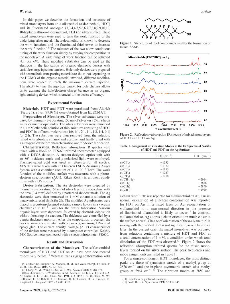
a chain tilt of∼30�was reported for n-alkanethiol onAu, a near-normal orientation of a helical conformation was reportedfor FDT on Au. In a mixed layer on Au, reorientation ofn-alkanethiol to a near-normal direction in the presenceof fluorinated alkanethiol is likely to occur.11 In contrast,n-alkanethiol on Ag adopts a chain orientation much closer tothe surface normal. Change of orientation of the n-alkanethiol inmixing with fluorinated thiol is not significant, as will be shownlater. In the current case, the mixed monolayer was preparedfrom solutions containing a mixture of HDT and FDT ata total concentration of 1 mM, a condition under which totaldissolution of the FDT was observed.12. Figure 2 shows thereflection-absorption infrared spectra for the mixed mono-layers formed on the silver surface. The peak frequencies andmode assignments are listed in Table 1.
For a single-component HDT monolayer, the most distinctpeaks are those of symmetric stretch of a methyl group at2876 cm-1 and the in-plane asymmetric stretch of a methylgroup at 2964 cm-1.10 The vibration modes at 2850 and
Figure 1. Structures of thiol compounds used for the formation ofmixed-SAMs.
Figure 2. Reflection-absorption IR spectra ofmixedmonolayersof HDT and FDT on Ag.
Table 1. Assignment of Vibration Modes in the IR Spectra of SAMs
of HDT and FDT on the Ag Surface
FDT (cm-1) HDT (cm-1)
νs(CF3) ∼1333νs(CF3) ∼1372νs(CF2) ∼1153νa(CF2) ∼1247νa(CF2) ∼1218νa(CH3, ip) ∼2964νs(CH3) ∼2876νs(CH2) ∼2850νa(CH2) ∼2920
(8) de Boer, B.; Hadipour, A.; Mandoc, M.M.; vanWoudenbergh, T.; Blom, P.W. M. Adv. Mater. 2005, 17, 621–625.(9) Chang, Y. M.; Wang, L.; Su, W. F. Org. Electron. 2008, 9, 968–973.(10) (a) Laibinis, P. E.; Whitesides, G. M.; Allara, D. L.; Tao, Y. T.; Parikh, A.
N.; Nuzzo, R. G. J. Am. Chem. Soc. 1991, 113, 7152–7167. (b) Tsao, M. W.;Hoffmann, C. L.; Rabolt, J. F.; Johnson, H. E.; Castner, D. G.; Erdelen, C.;Ringsdorf, H. Langmuir 1997, 13, 4317–4322.
(11) Results to be published elsewhere.(12) Scott, R. L. J. Phys. Chem. 1958, 62, 136–145.
DOI: 10.1021/la900046bLangmuir 2009, 25(11), 6232–6238 6233
ArticleWu et al.

2920 cm-1 for symmetric and asymmetric stretching modes,respectively, for a methylene group are relatively weak, dueto the near-normal orientation of n-alkanthiol on Ag.10 Fora single-component FDT monolayer, the most distinct featuresare that for CF vibration modes appearing in the low-frequencyregion from ∼1000 to ∼1400 cm-1.13 For the SAMs of binarymixtures of HDT and FDT, peaks associated with CH3 and CF3
groups are present, with various intensities depending on thesolution composition. It is noted that the relative intensities ofvarious modes in the C-H stretch region are the same as that ofpure HDT monolayer, with the absolute intensities shrunken inproportion to the decreasing concentration. This is an indicationof a similar chain tilt in the mixed monolayer as in the puremonolayer. With the intensities of the CH3 mode at 2964 cm-1
and the CF3mode at 1333 cm-1 as markers, the relative ratios ofthe HDT and FDT in the mixed monolayer were calculatedon the basis of the respective integrated areas. Figure 3 shows theplot of surface composition as a function of solution com-position. A nearly linear relationship was obtained. That is,the surface composition is similar to the solution composition.
It is generally known that fluorocarbons and hydrocarbonsare not miscible.12 How do these two components distribute onthe metal surface? The IR vibration frequency is known to besensitive to the local environment of the vibrating dipole.14 For aphase-separated monolayer, most molecules experience an en-vironment similar to that of a single-component monolayer,except those molecules at the boundary of phase domains. Fora molecularly mixed monolayer, all of the molecules experiencea changing environment as the composition is varied. Figure 4shows the spectra region between 1200 and 1400 cm-1, where theC-F stretches are observed. The frequencies of the νs (CF3) andνs (CF2) bands shift toward lower values with increasing amountof HDT in the monolayer. This is attributed to the localenvironment change when the nonpolar n-alkanethiol is intro-duced around the fluorinated chains. The peaks associated withCH3 in the 2860-2960 cm-1 region show similar shift withconcentration. This suggests that the mixed monolayer is notgrossly phase-separated into domains of hydrocarbons andfluorocarbons, respectively. A similar argument was invokedin the mixed monolayer of biphenylthiol and p-trifluoromethyl-biphenylthiol.14 A rationale for the homogeneous distributionof the two components is the electrostatic stabilization ofa dipole by opposite dipoles.
X-ray photoelectron spectroscopy was also used to character-ize the mixed monolayer. The XPS spectra of F 1s, C 1s, and Ag3d for mixed SAMs are shown in Figure 5. It is noted that theintensity of the F 1s signal15 at 688.4 eV increases with increasingamount of FDT in the monolayer. In the C 1s spectra for thesingle-component FDT monolayer, there are three peaks at284.4, 290.6, and 293 eV, assigned to C 1s (CH2), C 1s(CF2), andC 1s(CF3), respectively, and for the pure HDT monolayer onAg, only C 1s (CH2) at 284.4 eV was observed. For the mixedmonolayers on silver, the relative intensities of C 1s (CF2) and C1s (CF3) toC 1s (CH2) change, as expected, with the compositionof the solution: the intensities of C 1s (CF2) and C 1s (CF3)increase and that of C1s(CH2) decreases with increasing FDTconcentration. It is interesting to note that the binding energies
of C 1s (CF2) and C 1s (CF3) also shifted to higher bindingenergy with increasing amount of HDT in the mixedmonolayer,whereas the binding energy of C 1s (CH2) shifts to lower valueswith increasing amount of FDT, presumably due to the localpolarity changes. A quantitative calculation of the surfaceconcentration based on the intensities of the F 1s signal yieldeda near-linear plot similar to that obtained from IR spectra inFigure 3. This confirms that the surface composition of themixed monolayer is similar to the solution composition.
Contact angle on the monolayer-covered surface wasmeasured using water and n-hexadecane (HD) as the wettingliquids. As shown in Figure 6a, the contact angle θ(HD) on theFDT monolayer is higher than that on HDT monolayer,suggesting the FDT monolayer surface is more “oleophobic”than the HDT monolayer surface, presumably because of theweaker dispersive interaction between the hydrocarbons and
Figure 3. Plot of surface composition as a function of solutioncomposition, based on the integrated areas under the νs (CF3) band(∼1333 cm-1) and νa (CH3) band (∼2964 cm-1), for the mixedSAMs.
Figure 4. νs (CFx) band in the range of 1400-1200 cm-1 andνs (CHx) band in the range of 2800-3000 cm-1 for mixed SAMson Ag.
(13) Ren, Y. Z.; Iimura, K.; Ogawa, A.; Kato, T. J. Phys. Chem. B 2001, 105,4305–4312.(14) (a) Kang, J. F.; Ulman, A.; Liao, S.; Jordan, R. Langmuir 1999, 15, 2095–
2098. (b) Kang, J. F.; Liao, S.; Jordan, R.; Ulman, A. J. Am. Chem. Soc. 1998, 120,9662–9667.(15) (a) Shaporenko, A.; Cyganik, P.; Buck, M.; Ulman, A.; Zharnikov, A.
Langmuir 2005, 21, 8204–8213. (b) Zharnikov, M.; Grunze, M. J. Vacuum Sci.Technol. B 2002, 20, 1793–1807.
DOI: 10.1021/la900046b Langmuir 2009, 25(11),6232–62386234
Article Wu et al.

fluorinated surface than between hydrocarbons themselves.16
For a mixed monolayer, the contact angle exhibits a steadyincrease with increasing surface concentration of the FDTcomponent due to a steady decrease in dispersive interactionof the surface with hexadecane. The water contact angle is alsohigher on fluorinated surface than on hydrocarbon surface(Figure 6b). This is in agreement with an earlier paper.17
However, the water contact angle increases with increasingamount of FDT and reaches a plateau at a surface FDTconcentration of 60%. Both polar interaction and dispersive
interaction contribute to the work of adhesion and thus thecontact angle.18 Water interacts with the surface through bothdispersive interaction (with HDT) and polar interaction (withFDT). By replacing the HDT with FDT in the SAM, thedispersive component decreases and the polar componentincreases. The two opposing effects on contact angle may giverise to the nonmonotonous behavior in water contact angle.
The work functions (j) of various mixed monolayer surfaceswere measured by photoelectron spectrometer AC2. The freshlyprepared bare silver substrate gave a work function j of4.67 eV.2c For a single-component HDT-monolayer-coveredAg surface, the j value decreased to about 4.1 eV, whereas fora single-component FDT-monolayer-covered Ag, the j valueincreased to about 5.8 eV. The opposite effect on the work
Figure 5. XPS spectra of various mixed SAMs on Ag.
Figure 6. Contact angle of (a) hexadecane and (b) water as afunction of surface composition.
Figure 7. Work function as a function of the amount of FDT inthe monolayer on Ag. The inset shows the photocurrent trace forAg modified with a monolayer of FDT:HDT 1:1.
Table 2. Work Functions of Ag Substrates Modified by Mixed SAM
of FDT and HDTa
mixing ratio (FDT:HDT) work function (eV)
1:0 ∼5.834:1 ∼5.532:1 ∼5.251:1 ∼4.891:2 ∼4.651:4 ∼4.400:1 ∼4.10
aThe work function of bare Ag in this study was ∼4.67 eV.
(16) Chaudhury, M. K. Mater. Sci. Eng. 1996, R16, 97–159.(17) Graupe, M.; Takenaga, M.; Koini, T.; Colorado, R.Jr.; Randall Lee, T. J.
Am. Chem. Soc. 1999, 121, 3222–3223.(18) Fowkes, F.M.; Riddle, F. L.Jr.; Pastore,W. E.;Weber, A. A.Colloids Surf.
1990, 43, 367–387.
DOI: 10.1021/la900046bLangmuir 2009, 25(11), 6232–6238 6235
ArticleWu et al.
function is believed to be due to the opposite dipole direction ofthe alkyl and fluorinated alkyl moieties, mainly contributed bythe terminal methyl and trifluoromethyl groups, respectively.19
Theoretical calculations also show that the surface dipole isdominated by the intrinsic dipole of the molecule, with a smallcontribution from sulfur-metal bond.20 For the mixed mono-layer-modified Ag, the measured work functions lie between4.1 and 5.8 eV and varied linearly with the surface compositions(Figure 7). The results are summarized in Table 2.
It is noted that the square root of the counting rate as afunction of photon energy shows a straight line above a photo-emission threshold energy (work function) for all of the mixedmonolayers (the curve for Ag modified with monolayer of1:1 FDT:HDT is shown in the inset). This suggests amolecularlymixed monolayer because of the homogeneous environment ofthe substrate. The linear correlation in Figure 7 also suggeststhat by controlling the composition of the thiol solution, a workfunction anywhere between the two extreme values can beprepared. It is interesting to note that intramolecular polarbonds can be used to tune continuously the ionization energy(IE) of a thin organic film by mixing two components.21
Effect of Mixed SAM on the Charge Injection between
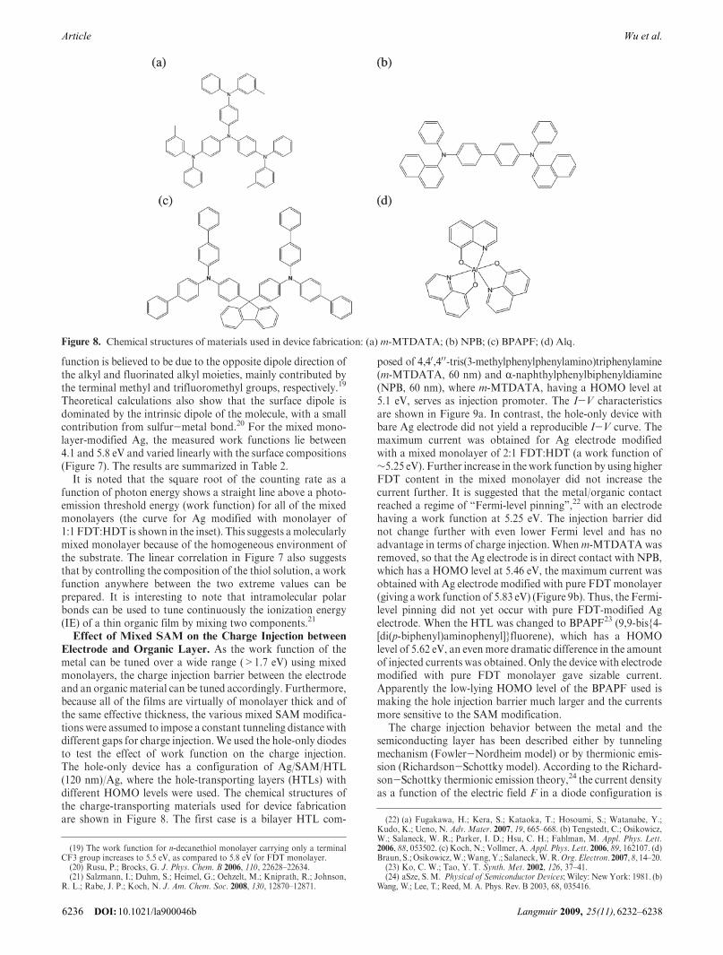
Electrode and Organic Layer. As the work function of themetal can be tuned over a wide range (>1.7 eV) using mixedmonolayers, the charge injection barrier between the electrodeand an organic material can be tuned accordingly. Furthermore,because all of the films are virtually of monolayer thick and ofthe same effective thickness, the various mixed SAM modifica-tions were assumed to impose a constant tunneling distance withdifferent gaps for charge injection.We used the hole-only diodesto test the effect of work function on the charge injection.The hole-only device has a configuration of Ag/SAM/HTL(120 nm)/Ag, where the hole-transporting layers (HTLs) withdifferent HOMO levels were used. The chemical structures ofthe charge-transporting materials used for device fabricationare shown in Figure 8. The first case is a bilayer HTL com-
posed of 4,40,40 0-tris(3-methylphenylphenylamino)triphenylamine(m-MTDATA, 60 nm) and R-naphthylphenylbiphenyldiamine(NPB, 60 nm), where m-MTDATA, having a HOMO level at5.1 eV, serves as injection promoter. The I-V characteristicsare shown in Figure 9a. In contrast, the hole-only device withbare Ag electrode did not yield a reproducible I-V curve. Themaximum current was obtained for Ag electrode modifiedwith a mixed monolayer of 2:1 FDT:HDT (a work function of∼5.25 eV). Further increase in the work function by using higherFDT content in the mixed monolayer did not increase thecurrent further. It is suggested that the metal/organic contactreached a regime of “Fermi-level pinning”,22 with an electrodehaving a work function at 5.25 eV. The injection barrier didnot change further with even lower Fermi level and has noadvantage in terms of charge injection. Whenm-MTDATAwasremoved, so that the Ag electrode is in direct contact with NPB,which has a HOMO level at 5.46 eV, the maximum current wasobtained with Ag electrode modified with pure FDTmonolayer(giving awork function of 5.83 eV) (Figure 9b). Thus, the Fermi-level pinning did not yet occur with pure FDT-modified Agelectrode. When the HTL was changed to BPAPF23 (9,9-bis{4-[di(p-biphenyl)aminophenyl]}fluorene), which has a HOMOlevel of 5.62 eV, an even more dramatic difference in the amountof injected currents was obtained. Only the device with electrodemodified with pure FDT monolayer gave sizable current.Apparently the low-lying HOMO level of the BPAPF used ismaking the hole injection barrier much larger and the currentsmore sensitive to the SAM modification.
The charge injection behavior between the metal and thesemiconducting layer has been described either by tunnelingmechanism (Fowler-Nordheim model) or by thermionic emis-sion (Richardson-Schottky model). According to the Richard-son-Schottky thermionic emission theory,24 the current densityas a function of the electric field F in a diode configuration is
Figure 8. Chemical structures of materials used in device fabrication: (a) m-MTDATA; (b) NPB; (c) BPAPF; (d) Alq.
(19) The work function for n-decanethiol monolayer carrying only a terminalCF3 group increases to 5.5 eV, as compared to 5.8 eV for FDT monolayer.(20) Rusu, P.; Brocks, G. J. Phys. Chem. B 2006, 110, 22628–22634.(21) Salzmann, I.; Duhm, S.; Heimel, G.; Oehzelt, M.; Kniprath, R.; Johnson,
R. L.; Rabe, J. P.; Koch, N. J. Am. Chem. Soc. 2008, 130, 12870–12871.
(22) (a) Fugakawa, H.; Kera, S.; Kataoka, T.; Hosoumi, S.; Watanabe, Y.;Kudo, K.; Ueno, N. Adv. Mater. 2007, 19, 665–668. (b) Tengstedt, C.; Osikowicz,W.; Salaneck, W. R.; Parker, I. D.; Hsu, C. H.; Fahlman, M. Appl. Phys. Lett.2006, 88, 053502. (c) Koch, N.; Vollmer, A. Appl. Phys. Lett. 2006, 89, 162107. (d)Braun, S.; Osikowicz,W.;Wang, Y.; Salaneck,W.R.Org. Electron. 2007, 8, 14–20.
(23) Ko, C. W.; Tao, Y. T. Synth. Met. 2002, 126, 37–41.(24) aSze, S. M. Physical of Semiconductor Devices; Wiley: New York: 1981. (b)
Wang, W.; Lee, T.; Reed, M. A. Phys. Rev. B 2003, 68, 035416.
DOI: 10.1021/la900046b Langmuir 2009, 25(11),6232–62386236
Article Wu et al.

given by
JRS ¼ A�T2 exp -ΦB -βRS
ffiffiffiffiF
p
kBT
!ð1Þ
where A* = 4πqm* kB2 /h3 is the Richardson const-
ant, βRS ¼ffiffiffiffiffiffiffiffiffiq3
4πεε0
qT is the temperature, ΦB is the barrier height
at interface, q is the electric charge, m* is the effective mass ofcarrier, h and kB are Plank’s and Boltzmann’s constants,respectively, ε0 is the vacuum permittivity, and εr is relativedielectric constant. From eq 1, a linear correlation between ln(J)and ΦB is expected if the temperature and external electric fieldare fixed. In contrast, in the Fowler-Nordheim tunnelingmodel, the ln(J) is expected to correlate with (ΦB)
1.5 if thetunneling distance in eq 2 is assumed to be the same with all ofthe mixed monolayers.
JFN∼V2 exp -4ffiffiffiffiffiffiffi2m
pΦB
32
3qpF
!ð2Þ
Figure 10 presents the plots of ln(J) versus ΔΦ, which is thedifference between the work function of mixed-SAM-modifiedAg anode and HOMO level of NPB. A linear dependenceof ln(J) versus ΔΦ is obtained at several driving voltages, inagreement with that expected from Richardson-Schottkythermionic emission theory. Thus, the charge injection behavioris controlled by the injection barrier heights.
Top-emitting OLEDs were also fabricated to test the effect ofwork function on the charge injection and performance of thedevices. The first device has a configuration of Ag/SAM/m-MTDATA(20 nm)/NPB(30 nm)/Alq(50 nm)/LiF (10 nm)/Al(2 nm)/Ag (25 nm), where Alq stands for tris(8-hydroxyquino-lino)aluminum(III) and m-MTDATA serves as an injectionpromoter as in the case of hole-only device. Very thin layer ofcathodewas used to allow for light output from the cathode side.The I-V characteristic is shown in Figure 11a. The maximumcurrent was again obtained for Ag electrode modified with amixed monolayer of 2:1 FDT:HDT. Further increase in thework function by using higher FDT content in the mixedmonolayer did not increase the current further. On the otherhand, the current efficiency, shown in Figure 11b and the inset,of the devices exhibits a maximum with a Ag electrode modifiedwith a 1:1 FDT:HDT monolayer (a work function of 4.89 eV).We suggest that the hole and electron carriers are more balancedwith this particular modified electrode. Larger injection barrier(by having decreasing FDT content) leads to insufficient holecarriers, and smaller barrier (by having increasing FDT content)leads to excessive hole carriers, both of which will result in lowerefficiency because of deviation from a balanced charge carriers.When m-MTDATA was removed, so that the Ag electrode wasin direct contact with NPB, the maximum current was obtainedwith a Ag electrode modified with pure FDT monolayer as inthe hole-only device (Figure 12). The Ag electrode yieldingmaximum current in the presence of m-MTDATA gave very
Figure 9. I-V characteristics in the hole-onlydeviceswithadeviceconfiguration of Ag/SAM/HTL/Ag.
Figure 10. Dependence of ln(J) onΔΦ at various driving voltages.
DOI: 10.1021/la900046bLangmuir 2009, 25(11), 6232–6238 6237
ArticleWu et al.

low current now. Thus, with a properly modified Ag electrode,the injection layer can be eliminated. The current efficiency plotshows that the Ag electrode modified with a 2:1 FDT:HDTmonolayer gave the highest current efficiency. Increasing theFDT content in the monolayer increases the current but not thecurrent efficiency. This suggests that the hole/electron chargesare more balanced with Ag modified with a 2:1 FDT:HDTmonolayer. In contrast to the case with a m-MTDATA bufferlayer, a higher work function is needed to have sufficient holeinjection and to reach charge balance. Further increase in workfunction, as provided by Ag modified with a pure FDT mono-layer, will increase the hole charges further to exceed the electroncharges and decrease the current efficiency. The device withBPAPF as a hole-transporting layer was also prepared, and thedevice characteristics are shown in Figure 13. With an evenlower lying HOMO level of BPAPF, both the maximum current
and luminance efficiency occurred with a Ag anode modifiedwith pure FDT monolayer. Thus, the increased barrier betweenthe anode and BPAPF layer results in reduced hole carrierinjection. Only a FDT-modified electrode provides enoughcurrent, and the hole carriers are better matching up with theelectron carriers.
Conclusion
In conclusion, we demonstrated that the mixed monolayersformed fromHDTandFDTon silver substrate are homogeneousmixtures of the two components. The opposite dipoles of the twocomponents can be used to tune the work function of silver metalover a wide range, from 4.1 eV for HDT-modified surface to5.8 eV for FDT-modified surface. Near-linear variation in workfunction was obtained by using a mixed monolayer formed fromthe two components. This provides easy access to all kinds ofwork functions that may be needed in conjunction with differentHOMO levels of organic semiconductors that may used indevices. The same approach can be applied on other substratesurfaces. For example, the work function ofAu can bemodulatedby the same mixtures here to vary from 4.4 to 5.9 eV. Hole-onlydevices with Ag as anodes demonstrate the effect of electrodework function on charge injection. With different HTLs used,there is a matching modification of the electrode to generate thehighest current. The varied current injection can be used to tunethe hole-electron charge balance in an OLED device, as demon-strated by variation of current efficiency as a function of currentinjection.
Acknowledgment. We thank the Ministry of Economics,Republic of China, and Academia Sinica for financial support.
Figure 11. (a) I-V characteristics and (b) current efficiency plot inthe TOLEDs with a device configuration of Ag (100 nm)/SAM/m-MTDATA (30 nm)/NPB (20 nm)/Alq (50 nm)/LiF (1 nm)/Al(2 nm)/Ag (25 nm).
Figure 12. (a) I-V characteristics and (b) current efficiency plot inthe TOLEDs with a device configuration of Ag (100 nm)/SAM/NPB (50 nm)/Alq (50 nm)/LiF (1 nm)/Al (2 nm)/Ag (25 nm).
Figure 13. (a) I-V characteristics and (b) current efficiency plot inthe TOLEDs with a device configuration of Ag (100 nm)/SAM/BPAPF (50 nm)/Alq (50 nm)/LiF (1 nm)/Al (2 nm)/Ag (25 nm).
DOI: 10.1021/la900046b Langmuir 2009, 25(11),6232–62386238
Article Wu et al.