continuous mixed flow grain dryers - kentra assembly instructions.pdf · continuous mixed flow...
TRANSCRIPT

CONTINUOUSMIXED FLOW
GRAIN DRYERS
Dryer Assembly Instructions© 1990,1992,1994 Kentra Grain Systems Limited - All Rights Reserved


Assembly Instructions
93.24.03 © Kentra Grain Systems Limited - 1993 Page: i
Table of Contents
Preface . . . . . . . . . . . . . . . . . . . . . . . . . . . . . . . . . . . . . . . . . . . . . . . . . . . . . . . . . . . . . . . . . . . . . . . . . iv
Dryer Foundation . . . . . . . . . . . . . . . . . . . . . . . . . . . . . . . . . . . . . . . . . . . . . . . . . . . . . . . . . . . . . . . . . iv
Dryer Assembly . . . . . . . . . . . . . . . . . . . . . . . . . . . . . . . . . . . . . . . . . . . . . . . . . . . . . . . . . . . . . . . . . . iv
1. Discharge Unit . . . . . . . . . . . . . . . . . . . . . . . . . . . . . . . . . . . . . . . . . . . . . . . . . . . . . . . . . . . . . 1
2. Drying Column and Exhaust Plenum . . . . . . . . . . . . . . . . . . . . . . . . . . . . . . . . . . . . . . . . . . 2a. Drying Column Assembly . . . . . . . . . . . . . . . . . . . . . . . . . . . . . . . . . . . . . . . . . . . . . . . . . 2b. Exhaust Plenum . . . . . . . . . . . . . . . . . . . . . . . . . . . . . . . . . . . . . . . . . . . . . . . . . . . . . . . . . 4
3. Inlet Plenum and Furnace Assembly . . . . . . . . . . . . . . . . . . . . . . . . . . . . . . . . . . . . . . . . . . 7a. Inlet Plenum . . . . . . . . . . . . . . . . . . . . . . . . . . . . . . . . . . . . . . . . . . . . . . . . . . . . . . . . . . . . 7b. Furnace Unit . . . . . . . . . . . . . . . . . . . . . . . . . . . . . . . . . . . . . . . . . . . . . . . . . . . . . . . . . . . . 9
4. Temperature Probes . . . . . . . . . . . . . . . . . . . . . . . . . . . . . . . . . . . . . . . . . . . . . . . . . . . . . . . 14
5. Proximity Switches . . . . . . . . . . . . . . . . . . . . . . . . . . . . . . . . . . . . . . . . . . . . . . . . . . . . . . . . 16a. Reserve Section . . . . . . . . . . . . . . . . . . . . . . . . . . . . . . . . . . . . . . . . . . . . . . . . . . . . . . . . 16b. Discharge Hopper . . . . . . . . . . . . . . . . . . . . . . . . . . . . . . . . . . . . . . . . . . . . . . . . . . . . . . 16
6. Pre-commissioning Checks . . . . . . . . . . . . . . . . . . . . . . . . . . . . . . . . . . . . . . . . . . . . . . . . 18a. Electrical Inspection (Before Mains Power is Applied) . . . . . . . . . . . . . . . . . . . . . . . . 18b. Electrical Inspection (After Mains Power is Applied) . . . . . . . . . . . . . . . . . . . . . . . . . . 18c. Fuel Supply Inspection and Installation . . . . . . . . . . . . . . . . . . . . . . . . . . . . . . . . . . . . . 18d. Discharge Unit Inspection . . . . . . . . . . . . . . . . . . . . . . . . . . . . . . . . . . . . . . . . . . . . . . . . 19e. Dryer Inspection . . . . . . . . . . . . . . . . . . . . . . . . . . . . . . . . . . . . . . . . . . . . . . . . . . . . . . . . 20
Index . . . . . . . . . . . . . . . . . . . . . . . . . . . . . . . . . . . . . . . . . . . . . . . . . . . . . . . . . . . . . . . . . . . . . . . . . . 21

Assembly Instructions
Page: ii © Kentra Grain Systems Limited - 1993 93.24.03
Figures
Figure 1 - Positioning Discharge Unit . . . . . . . . . . . . . . . . . . . . . . . . . . . . . . . . . . . . . . . . . . . . . . . . . . . . . . . 1Figure 2 - Type 25 Drying Zone Exhaust Side . . . . . . . . . . . . . . . . . . . . . . . . . . . . . . . . . . . . . . . . . . . . . . . . . . 2Figure 3 - Type 25 Drying Zone Inlet Side . . . . . . . . . . . . . . . . . . . . . . . . . . . . . . . . . . . . . . . . . . . . . . . . . . . . 2Figure 4 - Discharge Unit and Column (Dryer Model 1125) . . . . . . . . . . . . . . . . . . . . . . . . . . . . . . . . . . . . . . . . 3Figure 5 - Zone Corner Support Angle . . . . . . . . . . . . . . . . . . . . . . . . . . . . . . . . . . . . . . . . . . . . . . . . . . . . . . 4Figure 6 - Fan Support and Plenum Corner Bracing Angle Positions . . . . . . . . . . . . . . . . . . . . . . . . . . . . . . . . . . 4Figure 7 - Exhaust Plenum Assembly (Dryer Model 1125) . . . . . . . . . . . . . . . . . . . . . . . . . . . . . . . . . . . . . . . . . 6Figure 8 - Control Linkage Arrangement for adjustable cooling (Model 1325 shown) . . . . . . . . . . . . . . . . . . . . . . 7Figure 9 - Inlet Plenum up to level of Mixing Chamber (Dryer Model 1125) . . . . . . . . . . . . . . . . . . . . . . . . . . . . . 8Figure 10 - Furnace Inlet Restrictor Plate Position . . . . . . . . . . . . . . . . . . . . . . . . . . . . . . . . . . . . . . . . . . . . . . . 9Figure 11 - Position of Furnace Assembly (Dryer Model 1125) . . . . . . . . . . . . . . . . . . . . . . . . . . . . . . . . . . . . . 11Figure 12 - Furnace Heat Exchanger Placement (Dryer Model 1125) . . . . . . . . . . . . . . . . . . . . . . . . . . . . . . . . 12Figure 13 - Completed Furnace Mixing Chamber (Dryer Model 1125) . . . . . . . . . . . . . . . . . . . . . . . . . . . . . . . 13Figure 14 - Position of Hot Air PT100S Temperature Probe . . . . . . . . . . . . . . . . . . . . . . . . . . . . . . . . . . . . . . . 14Figure 15 - Position of Auto Discharge and Hot Grain PT100S Temperature Probes . . . . . . . . . . . . . . . . . . . . . . 15Figure 16 - PX2 Proximity Switch Positions . . . . . . . . . . . . . . . . . . . . . . . . . . . . . . . . . . . . . . . . . . . . . . . . . . . 16Figure 17 - Burner Oil Supply Line . . . . . . . . . . . . . . . . . . . . . . . . . . . . . . . . . . . . . . . . . . . . . . . . . . . . . . . . 17

Assembly Instructions
93.24.03 © Kentra Grain Systems Limited - 1993 Page: iii
Preface
The Kentra dryer has been designed for ease of installation, with as many parts as possible beingsent from the factory pre-assembled. Before starting to erect the dryer please check andfamiliarise yourself with all the component parts by refering to the packing list supplied.
Dryer Foundation
It is essential that the dryer is erected onto a suitably firm and level concrete foundation. If thedryer is to be erected out of doors the foundation must be designed in accordance with thefollowing British Standard: BS. 449, PART 1, 1970, CP3 CHAPTER V, PART 2, 1970 and the advice ofa local consultant engineer should be sought. If "drill-through" holding down bolts are usedinstead of grouted-in bolts you must ensure that they are capable of withstanding the very highpull-out forces which are unavoidable on tall outdoor dryers.
Dryer Assembly
Throughout this manual reference is made to the assembly of a dryer model 1125. The basicprinciples are the same for all models of dryer throughout the range. Reference to both thearrangement drawing and packing list supplied with your dryer will show the particulardifferences.
Assembly is started by placing the dryer discharge unit onto the prepared foundation takingparticular care to ensure that the top flange is absolutely level in both directions. Adjustmentscan be made by packing under the dryer base plates as required.
Following the installation of the discharge the drying zones are then lifted into position andbolted together, followed by the exhaust plenum chamber, inlet plenum chamber and finallyfurnace and furnace mixing chamber. All external joints should be sealed with the sealent stripsupplied.
After completing assembly, both the dryer and surrounding area should be carefully checkedto ensure that all tools, nuts, bolts, etc. have been cleared away.

Assembly Instructions
Page: iv © Kentra Grain Systems Limited - 1993 93.24.03
THIS PAGE IS INTENTIONALLY BLANK

Assembly Instructions
93.24.03 © Kentra Grain Systems Limited - 1993 Page: 1
Figure 1 - Positioning Discharge Unit
1. Discharge Unit
The discharge unit is lifted into position onto the prepared foundation as shown in Figure1 taking particular care to ensure that the top flanges are level in both directions. Anynecessary adjustments can be made by packing under the discharge leg footplates withmetal strips. After levelling the discharge unit it should be securely fastened to the hold-ing down bolts.
It is essential to position the discharge unit with the drive motor on the furnace side of thedryer. This will also assist the electrician when he comes to route his cables.

Assembly Instructions
Page: 2 © Kentra Grain Systems Limited - 1993 93.24.03
Figure 2 - Type 25 Drying Zone Exhaust Side
Figure 3 - Type 25 Drying Zone Inlet Side
2. Drying Column and Exhaust Plenum
a. Drying Column Assembly
All the drying zones are fitted with two half ducts on the exhaust (Fan) side of the dryer(See Figure 2 and Figure 3), and are marked as such when they are dispatched from ourfactory. It is imperative that the drying zones are positioned correctly with the exhaustside facing towards the fan side of the dryer.
All the drying zones can now be lifted into position. If suitable lifting equipment is avail-able then the drying zones can be bolted together in groups of up to four units at groundlevel prior to lifting into place. (See Figure 4, page 3)
When all the drying zones have been lifted into position the Reserve Section can be liftedinto position. Please ensure that all external joints have been adequately sealed beforelifting the reserve section into place.

Assembly Instructions
93.24.03 © Kentra Grain Systems Limited - 1993 Page: 3
Figure 4 - Discharge Unit and Column (Dryer Model 1125)

Assembly Instructions
Page: 4 © Kentra Grain Systems Limited - 1993 93.24.03
Figure 5 - Zone Corner Support Angle
Figure 6 - Fan Support and Plenum Corner Bracing Angle Positions
b. Exhaust Plenum
After building the dryer column and reserve section thenext stage is to assemble the dryer exhaust plenum. Allthe horizontal and vertical joints on the exhaust plenumare assembled with M8 x 16 setscrews apart from thevertical connection to the drying zone which isassembled with M8 x 25 setscrews.
The procedure for building the plenums on a Type 40& 50 dryers is identical with the exception that it isnecessary to fit joint support channels (supplied) on thecentre horizontal joints.
Start by bolting the two plenum roof/base side panels(#8010073) onto the bottom drying zone, not forgettingto seal the vertical joint between the panel and thedrying column. Do not forget to fit the zone cornersupport angle (See Figure 5) bolting at the top andbottom as well as the side. Next fit the plenumroof/base front panel (#8010083) as shown in Figure 7on page 6. After fitting these items continue to buildthe remainder of the plenum, the position of the fanconnection panels can be found by referring to thegeneral arrangement drawing for your particular modelof dryer at the rear of this manual. Under certaincircumstances the position of the fan(s) can be moved from the normal position.However, if you are not sure please contact us for advice.

Assembly Instructions
93.24.03 © Kentra Grain Systems Limited - 1993 Page: 5
It is recommended that all the bolts are left loose until all the panels are in place, andthen tightened.
Please refer to Figure 6 for the correct position of the plenum corner bracing angles(#8011113) and the fan support angles (#8011153).
After completing the assembly of the exhaust plenum sides and front, the roof panel(#8010063) can be lifted into position, sealed with the sealent strip supplied and bolted.The plenum base plate which includes the air control slides should be left out until thedryer is finished as it improves your access into the plenum by not fitting it at this stage.

Assembly Instructions
Page: 6 © Kentra Grain Systems Limited - 1993 93.24.03
Figure 7 - Exhaust Plenum Assembly (Dryer Model 1125)

Assembly Instructions
93.24.03 © Kentra Grain Systems Limited - 1993 Page: 7
8013053 - Short Crank, Cooling Door
8013073 - Connecting Rod
8013063 - Long Crank, Cooling Door
8013083 - Cooling Door Actuator Rod
8013093 - Actuator Rod Bracket
62.5
50
362
Figure 8 - Control Linkage Arrangement for adjustable cooling (Model 1325 shown)
3. Inlet Plenum and Furnace Assembly
a. Inlet Plenum
After completing assembly of the exhaust plenum the next stage is to build the inletplenum and furnace unit. Start by building the inlet plenum in the same way as theexhaust plenum up to the start of the furnace mixing chamber (See Figure 9, Page 8). Thelevel for yourp a r t i c u l a rm o d e l o fdryer can bef o u n d b yreferring tothe generalarrangementd r a w i n gsupplied withthis manual.You can alsoat this stage fitthe coolingfloor plates( # 8 0 1 1 1 4 3 )which sit ontop of theplenum panelh o r i z o n t a lf l a n g e s .A g a i n ,referring tot h e ar rangmentdrawing willindicate theposition of thecooling floorplates.
When fittingthe controllinkage for remote operation of the cooling doors it will be necessary to drill the plenumside to accept the actuator rod bracket in the position shown in figure 8.
It is not necessary to fit the plenum corner bracing angles here as the cooling floor platesperform the same function of stiffening the plenum and keeping it square.
Please note that the corners of the cooling floor plates are notched. The wider notch fitsinto the corner adjacent to the drying column.

Assembly Instructions
Page: 8 © Kentra Grain Systems Limited - 1993 93.24.03
Figure 9 - Inlet Plenum up to level of Mixing Chamber (Dryer Model 1125)
Assembly Instructions
93.24.03 © Kentra Grain Systems Limited - 1993 Page: 9
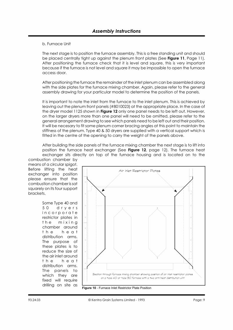
Figure 10 - Furnace Inlet Restrictor Plate Position
b. Furnace Unit
The next stage is to position the furnace assembly. This is a free standing unit and shouldbe placed centrally tight up against the plenum front plates (See Figure 11, Page 11).After positioning the furnace check that it is level and square, this is very importantbecause if the furnace is not level and square it may be impossible to open the furnaceaccess door.
After positioning the furnace the remainder of the inlet plenum can be assembled alongwith the side plates for the furnace mixing chamber. Again, please refer to the generalassembly drawing for your particular model to determine the position of the panels.
It is important to note the inlet from the furnace to the inlet plenum. This is achieved byleaving out the plenum front panels (#8010023) at the appropriate place. In the case ofthe dryer model 1125 shown in Figure 12 only one panel needs to be left out. However,on the larger dryers more than one panel will need to be omitted, please refer to thegeneral arrangement drawing to see which panels need to be left out and their position.It will be necesary to fit some plenum corner bracing angles at this point to maintain thestiffness of the plenum. Type 40 & 50 dryers are supplied with a vertical support which isfitted in the centre of the opening to carry the weight of the panels above.
After building the side panels of the furnace mixing chamber the next stage is to lift intoposition the furnace heat exchanger (See Figure 12, page 12). The furnace heatexchanger sits directly on top of the furnace housing and is located on to the
combustion chamber bymeans of a circular spigot.Before lifting the heatexchanger into positionplease ensure that thecombustion chamber is satsquarely on its four supportbrackets.
Some Type 40 and5 0 d r y e r si n c o r p o r a t erestrictor plates int h e m i x i n gchamber aroundt h e h e a tdistribution arms.The purpose ofthese plates is toreduce the size ofthe air inlet aroundt h e h e a tdistribution arms.The panels towhich they arefixed will requiredrilling on site as

Assembly Instructions
Page: 10 © Kentra Grain Systems Limited - 1993 93.24.03
required.
Figure 13 on page 13 shows the completed inlet plenum and furnace, at this point checkall the joints to make sure they are weather tight and tighten all the nuts and bolts.
If you have not already done so you can now lift and bolt the fans into position, togetherwith their silencers if supplied.

Assembly Instructions
93.24.03 © Kentra Grain Systems Limited - 1993 Page: 11
Figure 11 - Position of Furnace Assembly (Dryer Model 1125)

Assembly Instructions
Page: 12 © Kentra Grain Systems Limited - 1993 93.24.03
Figure 12 - Furnace Heat Exchanger Placement (Dryer Model 1125)

Assembly Instructions
93.24.03 © Kentra Grain Systems Limited - 1993 Page: 13
Figure 13 - Completed Furnace Mixing Chamber (Dryer Model 1125)
Assembly Instructions
Page: 14 © Kentra Grain Systems Limited - 1993 93.24.03
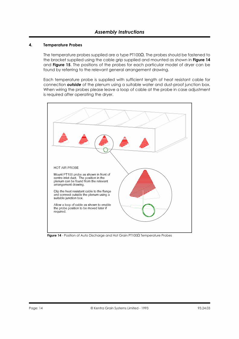
Figure 14 - Position of Auto Discharge and Hot Grain PT100S Temperature Probes
4. Temperature Probes
The temperature probes supplied are a type PT100S. The probes should be fastened tothe bracket supplied using the cable grip supplied and mounted as shown in Figure 14and Figure 15. The positions of the probes for each particular model of dryer can befound by referring to the relevant general arrangement drawing.
Each temperature probe is supplied with sufficient length of heat resistant cable forconnection outside of the plenum using a suitable water and dust-proof junction box.When wiring the probes please leave a loop of cable at the probe in case adjustmentis required after operating the dryer.

Assembly Instructions
93.24.03 © Kentra Grain Systems Limited - 1993 Page: 15
Figure 15 - Position of Auto Discharge and Hot Grain PT100S Temperature Probes

Assembly Instructions
Page: 16 © Kentra Grain Systems Limited - 1993 93.24.03
Figure 16 - PX2 Proximity Switch Positions
5. Proximity Switches
a. Reserve Section
As standard the dryer is supplied with one type PX2 proximity switch for the reservesection which senses when the dryer runs out of grain. In addition, if the dryer is suppliedfor Feed on Demand, a further two switches will be supplied for fitting in the reservesection. To fit the switches it is necessary to drill a 50mm hole in the side of the reservesection for each probe using a suitable hole cutter. The drilling positions are shown inFigure 16.
b. Discharge Hopper
To prevent blockage of the discharge mechanism due to failure of equipment after thedryer each discharge hopper is fitted with a PX2 proximity switch. These switches shouldbe fitted into the 50mm dia. hole adjacent to the hopper access hatch.

Assembly Instructions
93.24.03 © Kentra Grain Systems Limited - 1993 Page: 17
Figure 17 - Burner Oil Supply Line

Assembly Instructions
Page: 18 © Kentra Grain Systems Limited - 1993 93.24.03
6. Pre-commissioning Checks
Before using your KENTRA Dryer for the first time it is essential that you have the followingchecks carried out to ensure that your new Dryer is ready to be put into operation.Certain of these checks must only be carried out by qualified personnel (e.g. ElectricalChecks) and are marked as such where necessary.
a. Electrical Inspection (Before Mains Power is Applied)
The following checks are to be performed only by suitably qualified personnel.
i. The Control Panel should be firmly fixed to a secure wall and should beconnected to a suitably sized and protected Mains Supply.
ii. All Electrical Connections on both the Dryer and the Control PanelTerminal Rail should be thoroughly checked for good connection andtightness.
iii. All Cables from the Dryer Control Panel should be checked for continuity.Take care when doing this as there are sensitive electronic devices withinthe Control Panel. If you are in any doubt contact KENTRA Limited.
iv. Ensure that all Earth Connections are tight and if any RCCBs or ELCBs arefitted make sure that they function correctly.
v. Check and set the Overload Relays within the Control Panel, check theindividual Motor Serial Plates for the correct FLC Values.
vi. Thoroughly clean the inside of the Control Panel paying particularattention to loose strands of cable and drilling swarf which maycontaminate the Relay Contacts causing failure. Such damage is notcovered under Warranty!!!
b. Electrical Inspection (After Mains Power is Applied)
The following checks are to be performed only by suitably qualified personnel.
i. Check for correct operation of all Temperature Controllers and Indicators.
ii. Check that all Proximity Switches function correctly.
iii. Check all Electric Motors for correct rotation and adjust where necessary.
iv. Check that each Electric Motor's running current does not exceed theFLC shown on the Motor Rating Plate.
c. Fuel Supply Inspection and Installation (see Figure 17)
i. The Fuel Tank should be positioned so that the tank outlet is level with orabove the level of the Oil Burner Fuel Pump. If this is not the case contactKENTRA Limited for advise.

Assembly Instructions
93.24.03 © Kentra Grain Systems Limited - 1993 Page: 19
YOU HAVE BEEN WARNED!!!
ii. The Supply Line from the Tank to the Oil Burner must be installed withproper levels for a gravity system without air pockets.
iii. The Supply Line must be free of fuel leaks and there must be no air leaks.
iv. Any additional filters or strainers fitted to the fuel supply line must notimpede the fuel flow.
v. Termination of the oil supply pipe(s) must allow tension free connectionof the flexible oil hoses. Both oil and electrical connections must allow theburner to swing open.
vi. The oil filter supplied must be installed to protect the burner fuel pumpand system, and should be mounted at the termination of the oil supplyto the burner.
The following faults can occur if a filter is not fitted.
M Seizing of the pump drive
M Blocking of solenoid valves and nozzles
vii. The flexible hoses supplied with the burner are of a high quality andcovered with a woven wire sleeve cover. Properly installed they will giveyears of trouble free service. When installing care must be taken to ensurethat the hose is not twisted. In order to guarantee strain free installationthe hose should first be loosely fixed at one end, then moved through therequired hose movement 2 to 3 times, so that the hose can align withoutdistortion, and then tighten in position.
A second spanner must be used to counter hold when tightening.Particular care should be taken that the hoses do not foul each other orother equipment during operation. The hose connections can be installedfor either burner hinge direction as required.
d. Discharge Unit Inspection
i. The discharge unit must be checked to ensure that there is no debris inthe unit. (nuts, bolts, etc. left over from installation)
ii. The rollers must be checked for correct direction of rotation. This is mostimportant as serious damage could result if the rollers are allowed torotate in the wrong direction.

Assembly Instructions
Page: 20 © Kentra Grain Systems Limited - 1993 93.24.03
iii. The chain drive must be checked for correct tension and lubricated, andthe variable speed drive unit must be operated throughout its entirespeed range.
iv. The discharge trays must be checked for free movement using thewrench provided. The gas springs require quite a large effort to movethem but there should be no tight spots through the full travel of the traylever.
e. Dryer Inspection
i. Check that, where necessary, all access doors are securely fastened.
ii. Check that all air control slides are free to operate and adjust wherenecessary.
iii. If the Dryer is erected outside make sure that all the holding down boltsare secure and properly tightened.
iv. Finally check thoroughly around the Dryer to make sure that all bolts aretight and that all erection debris, such as nuts, bolts, etc., has beencleared up.

Assembly Instructions
93.24.03 © Kentra Grain Systems Limited - 1993 Page: 21
Index
Auto Discharge (15)Burner (17-19)Control Panel (18)Discharge (iv, 1, 3, 15, 16, 19, 20)
Speed (20)Trays (20)
Drying Column (2, 4, 7)Fans (10)Fuel Leaks (19)Fuel Pump (18, 19)Fuel Tank (18)Furnace (iv, 1, 7, 9-13)Grain (1, 15, 16)Manual (iv, 7)Oil (17-19)
Oil Filter (19)Proximity Switch (16)Push-button
Start (4, 7)Temperature (14, 15, 18)