contents · put your roper schedule for mep works, mep engineer is a single-level professional...
TRANSCRIPT
Planningengineer.net Privileged Document Page 1 of 134
Contents
Contents
Preface ........................................................................................................................................................................ 4
Introduction ................................................................................................................................................................ 5
Chapter 1: Division 11 - Equipment .............................................................................................................................. 6
1.1. Vehicle and Pedestrian Equipment ............................................................................................................... 6
Wheel Stops Installation ....................................................................................................................... 6
Pedestrian barrier/turnstile Card/ticket operated ................................................................................. 7
1.2. Food Service Equipment ............................................................................................................................... 9
1.3. Kitchen and Pantry Equipment ..................................................................................................................... 9
1.4. Entertainment Equipment .......................................................................................................................... 10
Chapter 2: Division 14 - Conveying Systems ............................................................................................................... 11
2.1. Lift Installation ........................................................................................................................................... 11
Auditorium platform lift, VIP platform lift, Dock platform lift .............................................................. 16
2.2. Escalator Installation .................................................................................................................................. 19
Interior commercial units (Car park, Monorail, Pre-function, Conference rooms, Wadi) ...................... 19
2.3. Work incidental to conveying systems ........................................................................................................ 24
Conveying Systems (Coordinating with other engineering installation, document, identification, testing and commissioning, tools and spares) ................................................................................................................ 24
2.4. Conveying Systems Installation ................................................................................................................... 26
Chapter 3: Division 21 - Fire Suppression ................................................................................................................... 27
3.1. Water Based Fire Suppression Systems ....................................................................................................... 27
Sprinkler Installation ........................................................................................................................... 27
Fire hose reel Installation: ................................................................................................................... 29
Fire Pumps Installation: ...................................................................................................................... 30
3.2. FM-200 system ........................................................................................................................................... 33
Gaseous Fire Suppression Systems ...................................................................................................... 33
3.3. Fire Suppression Water Storage.................................................................................................................. 36
Chapter 4: Division 22 - Plumbing .............................................................................................................................. 40
4.1. Plumbing piping and pumps ....................................................................................................................... 40
Drainage (above ground and underground): ....................................................................................... 40
Water Services (Cold, Hot, Grey and Irrigation): .................................................................................. 43
Water Heater ...................................................................................................................................... 45
Plumbing accessories Installation: ....................................................................................................... 47
Public Health Equipment..................................................................................................................... 51
4.2. Grey Water Treatment Plant: ..................................................................................................................... 54
4.3. RO Plant ..................................................................................................................................................... 56
Planningengineer.net Privileged Document Page 2 of 134
Contents
4.4. Grease Interceptor ..................................................................................................................................... 58
4.5. Plumbing Fixtures ....................................................................................................................................... 59
4.6. Sanitary fixtures ......................................................................................................................................... 60
4.7. Water Features .......................................................................................................................................... 61
4.8. Irrigation system: ....................................................................................................................................... 61
Chapter 5: Division 23 - Heating Ventilation and Air Conditioning .............................................................................. 66
5.1. Facility fuel system (Generator) .................................................................................................................. 66
5.2. HVAC piping and pumps ............................................................................................................................. 70
5.3. Condensate pipework ................................................................................................................................. 70
5.4. Under floor radiant cooling ........................................................................................................................ 73
5.5. HVAC Air distribution.................................................................................................................................. 75
Duct Work .......................................................................................................................................... 75
Acoustic lining to builders works shafts ............................................................................................... 77
Air diffusers ........................................................................................................................................ 79
Volume Control Damper (VCD) ........................................................................................................... 80
Fire/Smoke Damper (FSD/FD) ............................................................................................................. 82
5.6. HVAC Air cleaning devices .......................................................................................................................... 83
5.7. HVAC Equipment ........................................................................................................................................ 84
Plate heat exchangers ......................................................................................................................... 84
Kitchen exhaust precipitator ............................................................................................................... 86
Variable air volume unit ...................................................................................................................... 87
Chilled water fan coil unit ................................................................................................................... 87
Air handling units ................................................................................................................................ 88
Air movers: (AIR MOVER) .................................................................................................................... 89
5.8. Chiller ......................................................................................................................................................... 91
Chapter 6: Division 25 - Integrated Automation ......................................................................................................... 94
6.1. Building management system and automatic controls (BMS) ...................................................................... 94
Chapter 7: Division 26 - Electrical ............................................................................................................................... 98
6.2. LV and MV Electrical distribution ................................................................................................................ 98
6.3. Transformer ............................................................................................................................................. 103
6.4. Cable distribution: .................................................................................................................................... 108
6.5. Pump Control panel .................................................................................................................................. 109
6.6. Automatic transfer switch ........................................................................................................................ 109
6.7. Power distribution Board.......................................................................................................................... 110
6.8. Isolator and socket outlet points .............................................................................................................. 110
6.9. Facility electrical power generation and storing equipment ...................................................................... 111
6.10. Electrical and CATHODIC protection...................................................................................................... 113
Planningengineer.net Privileged Document Page 3 of 134
Contents
6.11. Lighting Installation: ............................................................................................................................. 115
Luminaires ........................................................................................................................................ 116
Lighting control system ..................................................................................................................... 116
General Knowledge........................................................................................................................... 117
Chapter 8: Division 27 - Communications ................................................................................................................. 118
7.1. Communications installation .................................................................................................................... 118
Telecommunication cabling .............................................................................................................. 118
Telecommunication conduit system .................................................................................................. 120
Telecommunication antenna system................................................................................................. 121
Telecommunication equipment ........................................................................................................ 123
Including call servers, signal servers, communication racks and fiber patch panels. .......................................... 123
7.2. Audio-Video Communications Installation ................................................................................................ 124
Chapter 9: Division 28 - Electronic Safety and Security ............................................................................................. 125
8.1. Electronic Access Control and Intrusion Detection .................................................................................... 125
Electric door strike and Card reader .................................................................................................. 126
Magnetic lock ................................................................................................................................... 127
Panic bar........................................................................................................................................... 128
8.2. Electronic Surveillance .............................................................................................................................. 129
Electronic Surveillance Cabling .......................................................................................................... 129
Electronic Surveillance Equipment and Accessories........................................................................... 129
8.3. Electronic Detection and Alarm ................................................................................................................ 130
Fire alarm cabling, Fire alarm telephone control cabling, Fire alarm multiple loops: .......................... 130
ELECTRONIC DETECTION AND ALARM equipment and accessories .................................................... 130
Fire alarm system ............................................................................................................................. 130
Magnetic door holder ....................................................................................................................... 133
Heat and smoke detector:................................................................................................................. 133
We always have more!! ........................................................................................................................................... 134

Planningengineer.net Privileged Document Page 4 of 134
Preface
Preface
PlanningEngineer.net is an online project management website, we are a PM Office online simulation aiming to
share knowledge, books, several courses as well as online consultancy.
One-size fits all, does not work to project management. You need to learn how to create your own plans as per
project conditions and requirements. We share new courses, ideas, approaches, and techniques, which help to
increase your project management knowledge to be able to create your own project management plans.
So, All what you may need for enhancing the perfect planning career, you will find it with us, our members is
our riches so we work in accordance with your needs and requirements to fit our services to benefit you.
This E-Book was the idea of Eng. Hany Ismael, He is a Civil Engineer BSc, Project Management Professional
certified PMP, MSc student at Liverpool University, involved in construction projects since 11 years, and working
as a Planning Manager. He likes to share Project Management Information and follow the rabid update of Project
Management Tools such as Primavera and Excel.
It was prepared by Eng. Meghdad Hajipour, An experienced SMPE project engineer with strong exposure across
end to end project engineering both critical and non-critical portfolios, programs and projects covering all
project lifecycle from designing into QA/QC, construction, commissioning and hand over, It was Reviewed and
Edited by Eng. Yasmeen Sultan, a Civil Engineer BSc with Four years’ experience of Project Management Business
Development, for our esteemed members, the book is named “ MEP Guide for Planning and Scheduling”,
Planning career is not a preserve for a specific engineering disciplines, actually any engineer will need planning
and scheduling in managing his project.
To make it easier for you, our E-Book will illustrate the planning and the time frame for MEP installations
processes. So our book is divided in to 9 chapters which will cover the following topics:
1. Equipment
2. Conveying Systems
3. Fire Suppressions
4. Plumbing
5. Heating Ventilation and Air conditioning
6. Integrated Automation
7. Electrical
8. Electronic Safety and Security
9. Electronic Surveillance
Planningengineer.net Privileged Document Page 5 of 134
Introduction
Introduction
Before commencement of any project, the first thing that we need to do is project planning. Any project manager
understands importance of planning a project well. Planning and scheduling are the main gear all organizations,
Every organization that delivers something, a product or a service, has production requirements and must have
the capability to succeed.
Most of Engineers believe that planning is for specific engineering disciplines construction projects, however As
Architect, Civil and MEP are the three gears of most Projects, we will be explaining herein by how to plan and
put your roper schedule for MEP works, MEP Engineer is a single-level professional classification responsible for
planning and design in the areas of mechanical, electrical, and plumbing (MEP) systems including developing
polices, standards, inspection procedures, and evaluation tools for MEP matters.
The MEP planning career includes so many duties, such as create master schedule for the execution of the
project, Prepare schedule plans to manage mechanical/electrical/plumbing (MEP) work of project, Plan for
resource deployment and cash flow to be made available during the project's entire execution phase and
Monitor project status for purposes of management and billing information, so we here introduce our EBook to
assist all Planning Engineers in their work and career.
Planningengineer.net Privileged Document Page 6 of 134
Division 11 - Equipment
Chapter 1: Division 11 - Equipment
1.1. Vehicle and Pedestrian Equipment
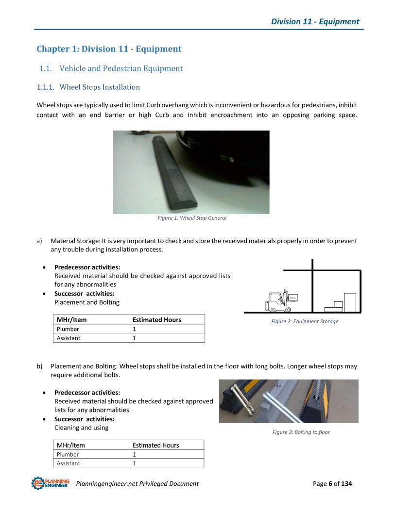
Wheel Stops Installation
Wheel stops are typically used to limit Curb overhang which is inconvenient or hazardous for pedestrians, inhibit
contact with an end barrier or high Curb and Inhibit encroachment into an opposing parking space.
a) Material Storage: It is very important to check and store the received materials properly in order to prevent any trouble during installation process.
Predecessor activities: Received material should be checked against approved lists for any abnormalities
Successor activities: Placement and Bolting
MHr/Item Estimated Hours
Plumber 1
Assistant 1
b) Placement and Bolting: Wheel stops shall be installed in the floor with long bolts. Longer wheel stops may require additional bolts.
Predecessor activities: Received material should be checked against approved lists for any abnormalities
Successor activities: Cleaning and using
MHr/Item Estimated Hours
Plumber 1
Assistant 1
Figure 2: Equipment Storage
Figure 1: Wheel Stop General View
Figure 3: Bolting to floor

Planningengineer.net Privileged Document Page 7 of 134
Division 11 - Equipment
Pedestrian barrier/turnstile Card/ticket operated
They Are forms of gates which allows one person to pass at a time and provide safety for pedestrians.
a) Material Storage: It is very important to check and store the received materials properly in order to prevent any trouble during installation process.
Predecessor activities: Received materials should be checked against approved lists for any abnormalities
Successor activities: Wiring
MHr/Item Estimated Hours
Electrician -
Plumber 1
Assistant 1
b) Wiring: Power cables shall be installed inside the equipment to feed the component.
Predecessor activities: Material storage
Successor activities: Arrangement and installation
MHr/10meter Estimated Hours
Electrician 2
Plumber
Assistant 2
Figure 5: Equipment Storage
Figure 4: Card/Ticket Pedestrian turnstile
Planningengineer.net Privileged Document Page 8 of 134
Division 11 - Equipment
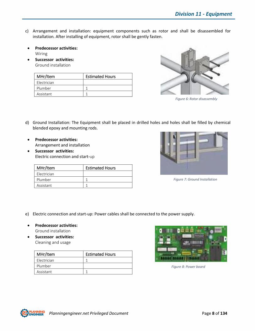
c) Arrangement and installation: equipment components such as rotor and shall be disassembled for installation. After installing of equipment, rotor shall be gently fasten.
Predecessor activities: Wiring
Successor activities: Ground installation
MHr/Item Estimated Hours
Electrician
Plumber 1
Assistant 1
d) Ground Installation: The Equipment shall be placed in drilled holes and holes shall be filled by chemical blended epoxy and mounting rods.
Predecessor activities: Arrangement and installation
Successor activities: Electric connection and start-up
MHr/Item Estimated Hours
Electrician
Plumber 1
Assistant 1
e) Electric connection and start-up: Power cables shall be connected to the power supply.
Predecessor activities: Ground installation
Successor activities: Cleaning and usage
MHr/Item Estimated Hours
Electrician 1
Plumber
Assistant 1
Figure 6: Rotor disassembly
Figure 7: Ground Installation
Figure 8: Power board
Planningengineer.net Privileged Document Page 9 of 134
Division 11 - Equipment
1.2. Food Service Equipment
Supply and install the following equipment including mixers, traps, flexible, pipes, and pipe connections until
wall outlets and inlets regarding the mechanical. Cables, wires, electrical connections until isolating switches,
socket outlets and wall outlets, and all associated fittings and accessories complete as per drawings.
Predecessor activities: Received material should be checked against approved lists for any abnormalities
Successor activities: Placement and usage
MHr/Item Estimated Hours
Electrician 1
Plumber 1
Assistant 2
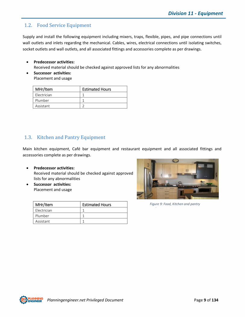
1.3. Kitchen and Pantry Equipment
Main kitchen equipment, Café bar equipment and restaurant equipment and all associated fittings and
accessories complete as per drawings.
Predecessor activities: Received material should be checked against approved lists for any abnormalities
Successor activities: Placement and usage
MHr/Item Estimated Hours
Electrician 1
Plumber 1
Assistant 1
Figure 9: Food, Kitchen and pantry equipment

Planningengineer.net Privileged Document Page 10 of 134
Division 11 - Equipment
1.4. Entertainment Equipment
Bespoke equipment and auditorium dais are entertaining equipment which shall be installed inside or outside
the auditorium.
Predecessor activities: Received material should be checked against approved lists for any abnormalities
Successor activities: Placement and usage
MHr/Item Estimated Hours
Electrician
Plumber 1
Assistant 1
Figure 10: Entertainment Equipment
Planningengineer.net Privileged Document Page 11 of 134
Division 14 – Conveying Systems
Chapter 2: Division 14 - Conveying Systems
2.1. Lift Installation
Passenger parking elevator, Service elevator, VIP elevator, Monorail elevator, Exterior WADI elevator
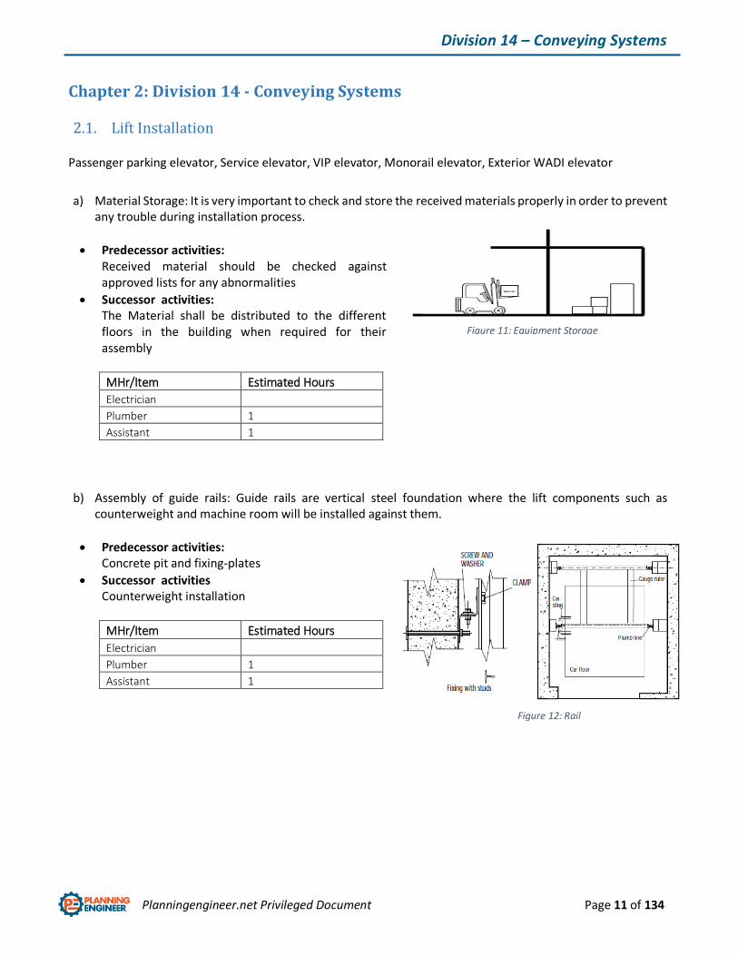
a) Material Storage: It is very important to check and store the received materials properly in order to prevent any trouble during installation process.
Predecessor activities: Received material should be checked against approved lists for any abnormalities
Successor activities: The Material shall be distributed to the different floors in the building when required for their assembly
MHr/Item Estimated Hours
Electrician
Plumber 1
Assistant 1
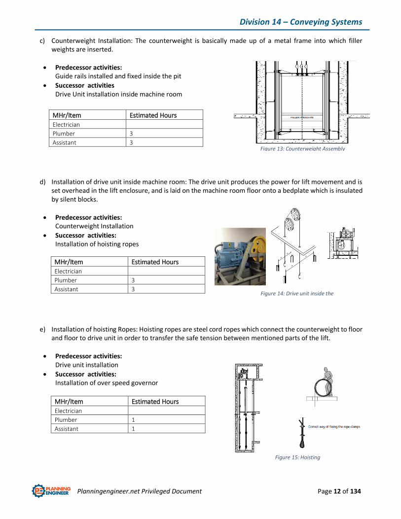
b) Assembly of guide rails: Guide rails are vertical steel foundation where the lift components such as counterweight and machine room will be installed against them.
Predecessor activities: Concrete pit and fixing-plates
Successor activities Counterweight installation
MHr/Item Estimated Hours
Electrician
Plumber 1
Assistant 1
Figure 11: Equipment Storage
Figure 12: Rail installation
Planningengineer.net Privileged Document Page 12 of 134
Division 14 – Conveying Systems
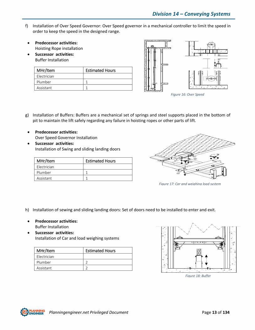
c) Counterweight Installation: The counterweight is basically made up of a metal frame into which filler weights are inserted.
Predecessor activities: Guide rails installed and fixed inside the pit
Successor activities Drive Unit installation inside machine room
d) Installation of drive unit inside machine room: The drive unit produces the power for lift movement and is set overhead in the lift enclosure, and is laid on the machine room floor onto a bedplate which is insulated by silent blocks.
Predecessor activities: Counterweight Installation
Successor activities: Installation of hoisting ropes
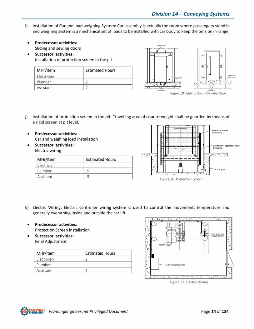
e) Installation of hoisting Ropes: Hoisting ropes are steel cord ropes which connect the counterweight to floor and floor to drive unit in order to transfer the safe tension between mentioned parts of the lift.
Predecessor activities: Drive unit installation
Successor activities: Installation of over speed governor
MHr/Item Estimated Hours
Electrician
Plumber 1
Assistant 1
MHr/Item Estimated Hours
Electrician
Plumber 3
Assistant 3
MHr/Item Estimated Hours
Electrician
Plumber 3
Assistant 3
Figure 13: Counterweight Assembly
Figure 14: Drive unit inside the machine room
Figure 15: Hoisting Ropes Installation
Planningengineer.net Privileged Document Page 13 of 134
Division 14 – Conveying Systems
f) Installation of Over Speed Governor: Over Speed governor in a mechanical controller to limit the speed in order to keep the speed in the designed range.
Predecessor activities: Hoisting Rope installation
Successor activities: Buffer Installation
MHr/Item Estimated Hours
Electrician
Plumber 1
Assistant 1
g) Installation of Buffers: Buffers are a mechanical set of springs and steel supports placed in the bottom of pit to maintain the lift safely regarding any failure in hoisting ropes or other parts of lift.
Predecessor activities: Over Speed Governor Installation
Successor activities: Installation of Swing and sliding landing doors
MHr/Item Estimated Hours
Electrician
Plumber 1
Assistant 1
h) Installation of sewing and sliding landing doors: Set of doors need to be installed to enter and exit.
Predecessor activities: Buffer Installation
Successor activities: Installation of Car and load weighing systems
MHr/Item Estimated Hours
Electrician
Plumber 2
Assistant 2
Figure 16: Over Speed Governor Installation
Figure 18: Buffer Installation
Figure 17: Car and weighing load system installation
Planningengineer.net Privileged Document Page 14 of 134
Division 14 – Conveying Systems
i) Installation of Car and load weighing System: Car assembly is actually the room where passengers stand in and weighing system is a mechanical set of loads to be installed with car body to keep the tension in range.
Predecessor activities: Sliding and sewing doors
Successor activities: Installation of protection screen in the pit
j) Installation of protection screen in the pit: Travelling area of counterweight shall be guarded by means of a rigid screen at pit level.
Predecessor activities: Car and weighing load installation
Successor activities: Electric wiring
k) Electric Wiring: Electric controller wiring system is used to control the movement, temperature and generally everything inside and outside the car lift.
Predecessor activities: Protection Screen installation
Successor activities: Final Adjustment
MHr/Item Estimated Hours
Electrician 2
Plumber
Assistant 2
MHr/Item Estimated Hours
Electrician
Plumber 2
Assistant 2
MHr/Item Estimated Hours
Electrician
Plumber .5
Assistant .5
Figure 19: Sliding Door / Sewing Door
Figure 20: Protection Screen
Figure 21: Electric Wiring
Planningengineer.net Privileged Document Page 15 of 134
Division 14 – Conveying Systems
l) Final Adjustment: After having carried out all the electric wiring, whole the lift assembly should be cleaned and safety limit switches, buffers, controllers, doors and drive unit should be checked.
Predecessor activities: Electric wiring
Successor activities: Commissioning and Start-up
MHr/Item Estimated Hours
Electrician 1
Plumber 1
Assistant 2
Planningengineer.net Privileged Document Page 16 of 134
Division 14 – Conveying Systems
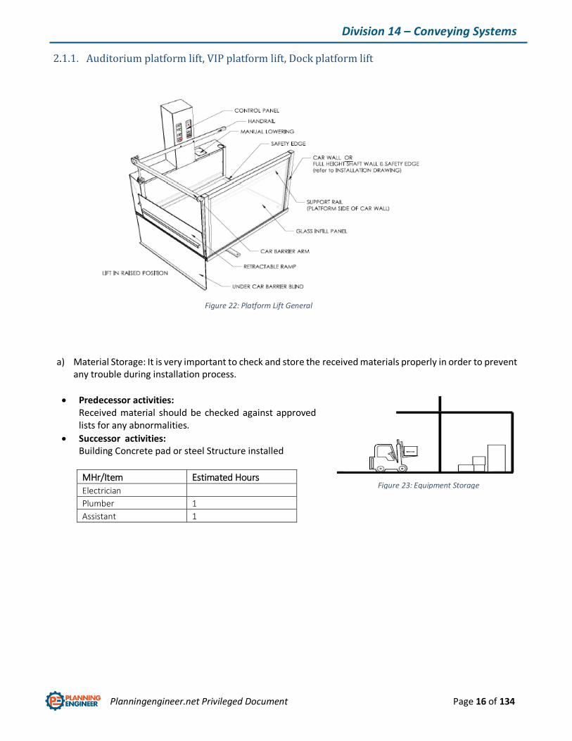
Auditorium platform lift, VIP platform lift, Dock platform lift
a) Material Storage: It is very important to check and store the received materials properly in order to prevent any trouble during installation process.
Predecessor activities: Received material should be checked against approved lists for any abnormalities.
Successor activities: Building Concrete pad or steel Structure installed
MHr/Item Estimated Hours
Electrician
Plumber 1
Assistant 1
Figure 23: Equipment Storage
Figure 22: Platform Lift General view

Planningengineer.net Privileged Document Page 17 of 134
Division 14 – Conveying Systems
b) Assembly of guide rails: Guide rails are vertical steel foundation normally L-Beams where following platform lift components such as platform and machine room will be installed inline.
Predecessor activities: Building Concrete pad or steel Structure installed
Successor activities Drive System Installation
MHr/Item Estimated Hours
Electrician
Plumber 2
Assistant 2
c) Drive System Installation: Drive system is an electromechanical set of motors, pillow blocks, and gearboxes on vibration and acoustic isolators on bed plate and concrete pad that shall be Place on structural supports and bearing plates. Securely fasten to building supports to prevent lateral displacement.
Predecessor activities: Guide rail installed
Successor activities Platform Installation
MHr/Item Estimated Hours
Electrician
Plumber 2
Assistant 2
d) Platform Installation: Platform is a package of equipment including car and surfaces, machine room and etc. where passengers stand in.
Predecessor activities: Drive unit installed
Successor activities: Platform Control room installation
MHr/Item Estimated Hours
Electrician
Plumber 3
Assistant 3
Figure 24: Guide Rail Assembly
Figure 25: Drive Unit
Figure 26: Platform installation

Planningengineer.net Privileged Document Page 18 of 134
Division 14 – Conveying Systems
e) Platform Control Box Installation and Electric wiring: If the control room is not installed with platform, it shall be carefully installed in control room structure placed in platform wall.
Predecessor activities: Platform Installation
Successor activities: Final Adjustment
MHr/Item Estimated Hours
Electrician 1
Plumber
Assistant 1
f) Final Adjustment: After having carried out all the electric wiring, whole the lift assembly should be cleaned and safety limit switches, buffers, controllers, doors and drive unit should be checked.
Predecessor activities: Control box and electric wiring
Successor activities: Commissioning and Start-up
MHr/Item Estimated Hours
Electrician 1.5
Plumber 1.5
Assistant 3
Planningengineer.net Privileged Document Page 19 of 134
Division 14 – Conveying Systems
2.2. Escalator Installation
Interior commercial units (Car park, Monorail, Pre-function, Conference rooms, Wadi)
a) Material Storage: It is very important to check and store the received materials properly in order to prevent any trouble during installation process.
Predecessor activities: Received material should be checked against approved lists for any abnormalities.
Successor activities: Framed Operation and Support Installation
MHr/Item Estimated Hours
Electrician
Plumber 1
Assistant 1
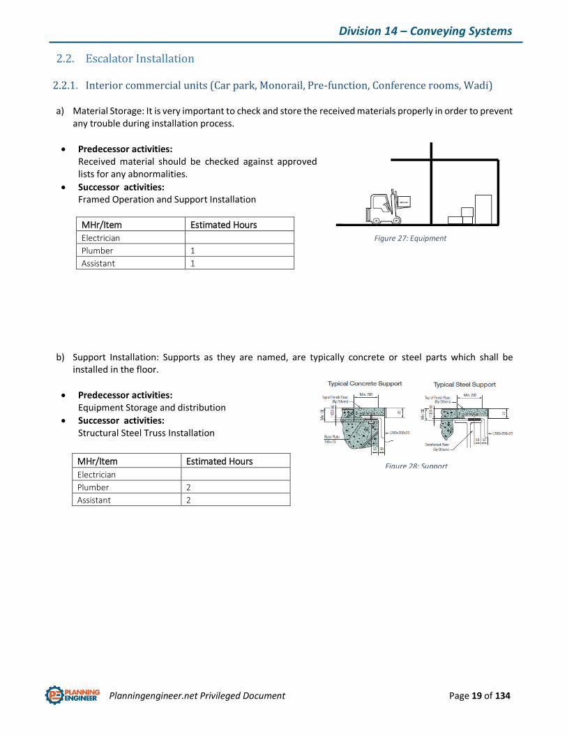
b) Support Installation: Supports as they are named, are typically concrete or steel parts which shall be installed in the floor.
Predecessor activities: Equipment Storage and distribution
Successor activities: Structural Steel Truss Installation
MHr/Item Estimated Hours
Electrician
Plumber 2
Assistant 2
Figure 27: Equipment Storage
Figure 28: Support Installation
Planningengineer.net Privileged Document Page 20 of 134
Division 14 – Conveying Systems
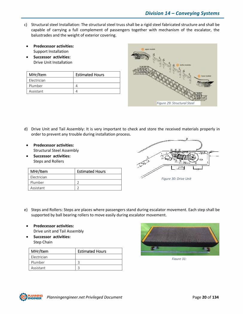
c) Structural steel Installation: The structural steel truss shall be a rigid steel fabricated structure and shall be capable of carrying a full complement of passengers together with mechanism of the escalator, the balustrades and the weight of exterior covering.
Predecessor activities: Support Installation
Successor activities: Drive Unit Installation
d) Drive Unit and Tail Assembly: It is very important to check and store the received materials properly in order to prevent any trouble during installation process.
Predecessor activities: Structural Steel Assembly
Successor activities: Steps and Rollers
e) Steps and Rollers: Steps are places where passengers stand during escalator movement. Each step shall be supported by ball bearing rollers to move easily during escalator movement.
Predecessor activities: Drive unit and Tail Assembly
Successor activities: Step Chain
MHr/Item Estimated Hours
Electrician
Plumber 4
Assistant 4
MHr/Item Estimated Hours
Electrician
Plumber 2
Assistant 2
MHr/Item Estimated Hours
Electrician
Plumber 3
Assistant 3
Figure 29: Structural Steel Assembly
Figure 30: Drive Unit
Figure 31: Step
Planningengineer.net Privileged Document Page 21 of 134
Division 14 – Conveying Systems
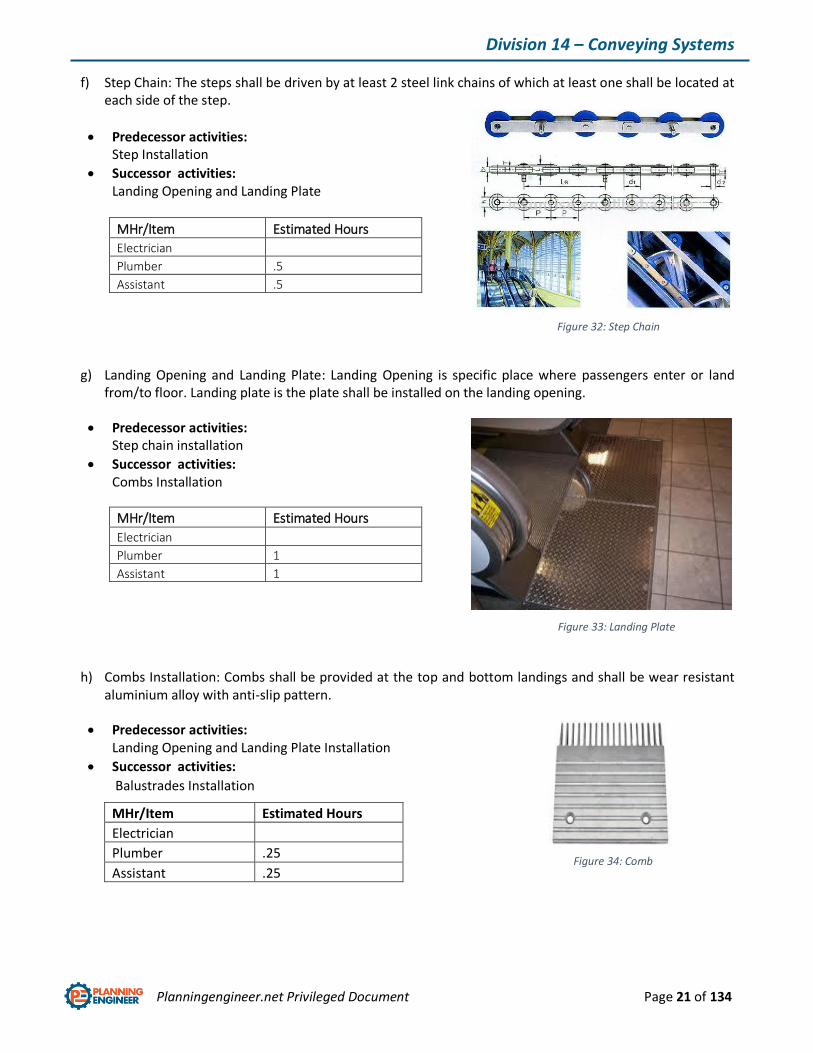
f) Step Chain: The steps shall be driven by at least 2 steel link chains of which at least one shall be located at each side of the step.
Predecessor activities: Step Installation
Successor activities: Landing Opening and Landing Plate
MHr/Item Estimated Hours
Electrician
Plumber .5
Assistant .5
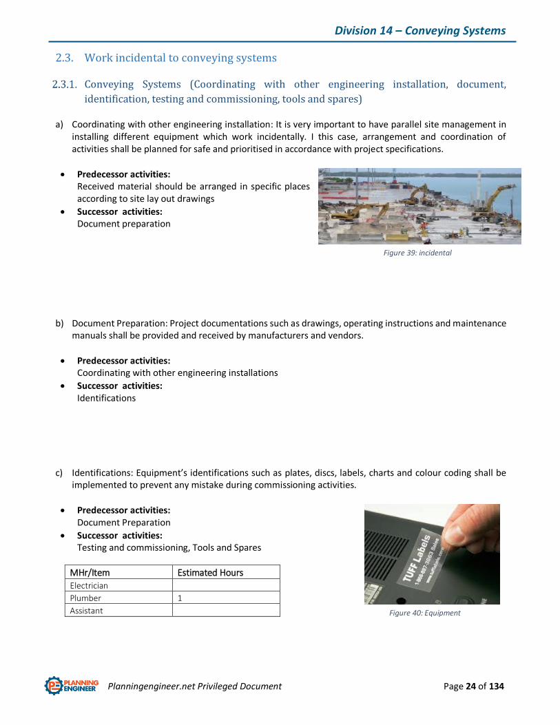
g) Landing Opening and Landing Plate: Landing Opening is specific place where passengers enter or land from/to floor. Landing plate is the plate shall be installed on the landing opening.
Predecessor activities: Step chain installation
Successor activities: Combs Installation
MHr/Item Estimated Hours
Electrician
Plumber 1
Assistant 1
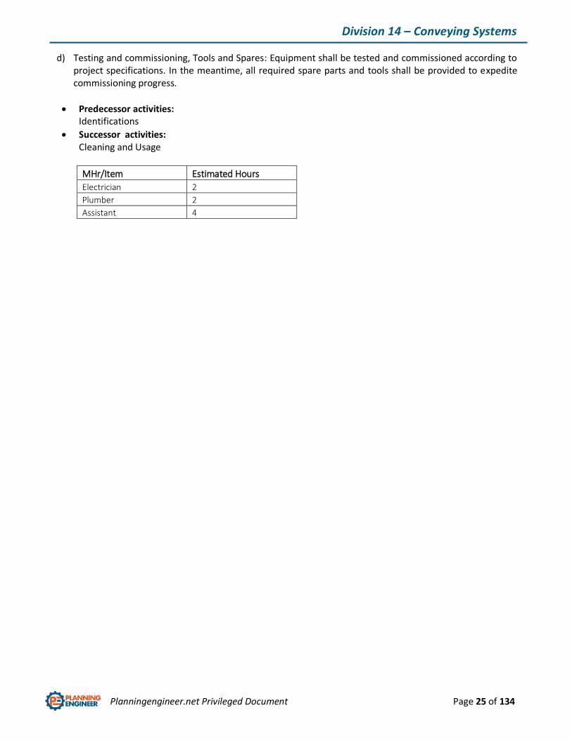
h) Combs Installation: Combs shall be provided at the top and bottom landings and shall be wear resistant aluminium alloy with anti-slip pattern.
Predecessor activities: Landing Opening and Landing Plate Installation
Successor activities:
Balustrades Installation
MHr/Item Estimated Hours
Electrician
Plumber .25
Assistant .25
Figure 32: Step Chain
Figure 33: Landing Plate
Figure 34: Comb

Planningengineer.net Privileged Document Page 22 of 134
Division 14 – Conveying Systems
i) Balustrades Installation: Solid balustrades shall be installed on each side of the escalator and shall consist of the following components: Skirting, Interior profile, Interior and exterior panelling, Balustrade decking, Extended newel.
Predecessor activities: Balustrades Installation
Successor activities: Dress Guard and External Cladding Installation
MHr/Item Estimated Hours
Electrician
Plumber .5
Assistant .5
j) Dress guard and external cladding Installation: These Accessories are designed to make a safe place preventing passenger’s dress trapping in gaps.
Predecessor activities: Balustrades Installation
Successor activities: Rubber handrail, safety Guard Installation
MHr/Item Estimated Hours
Electrician
Plumber .5
Assistant .5
k) Rubber handrail, safety Guard Installation: These Accessories are designed to make a safe place preventing passenger’s falling during escalator operation.
Predecessor activities: Dress Guard and External Cladding
Successor activities: Electric wiring and safety Check
MHr/Item Estimated Hours
Electrician
Plumber .5
Assistant .5
Figure 35: Balustrade
Figure 36: Dress Guard and External Cladding
Figure 37: Handrail

Planningengineer.net Privileged Document Page 23 of 134
Division 14 – Conveying Systems
l) Electric Wiring and safety check: These Accessories are designed to make a safe place preventing passenger’s falling during escalator operation.
Predecessor activities: Dress Guard and External Cladding
Successor activities: Electric wiring and safety Check
MHr/Item Estimated Hours
Electrician 1
Plumber
Assistant 1
Figure 38: Safety Devices
Planningengineer.net Privileged Document Page 24 of 134
Division 14 – Conveying Systems
2.3. Work incidental to conveying systems
Conveying Systems (Coordinating with other engineering installation, document,
identification, testing and commissioning, tools and spares)
a) Coordinating with other engineering installation: It is very important to have parallel site management in installing different equipment which work incidentally. I this case, arrangement and coordination of activities shall be planned for safe and prioritised in accordance with project specifications.
Predecessor activities: Received material should be arranged in specific places according to site lay out drawings
Successor activities: Document preparation
b) Document Preparation: Project documentations such as drawings, operating instructions and maintenance manuals shall be provided and received by manufacturers and vendors.
Predecessor activities: Coordinating with other engineering installations
Successor activities: Identifications
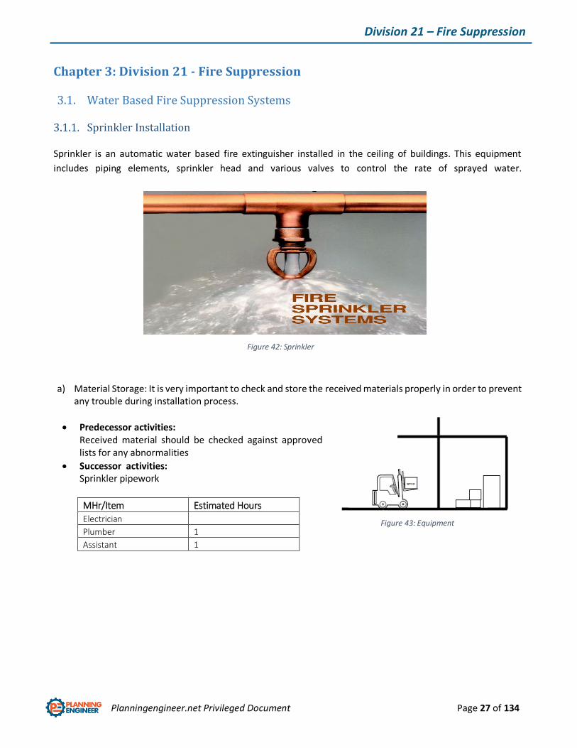
c) Identifications: Equipment’s identifications such as plates, discs, labels, charts and colour coding shall be implemented to prevent any mistake during commissioning activities.
Predecessor activities: Document Preparation
Successor activities: Testing and commissioning, Tools and Spares
MHr/Item Estimated Hours
Electrician
Plumber 1
Assistant
Figure 39: incidental installation
Figure 40: Equipment Labels
Planningengineer.net Privileged Document Page 25 of 134
Division 14 – Conveying Systems
d) Testing and commissioning, Tools and Spares: Equipment shall be tested and commissioned according to project specifications. In the meantime, all required spare parts and tools shall be provided to expedite commissioning progress.
Predecessor activities: Identifications
Successor activities: Cleaning and Usage
MHr/Item Estimated Hours
Electrician 2
Plumber 2
Assistant 4

Planningengineer.net Privileged Document Page 26 of 134
Division 14 – Conveying Systems
2.4. Conveying Systems Installation
a) Protective painting and decoration: Protecting activities such as removing protective coating, rapping, cleaning, polishing exposed surfaces and painting shall be done.
Predecessor activities: Received material should be arranged in specific places according to site lay out drawings.
Successor activities: Fittings and outlet preservation
MHr/Item Estimated Hours
Electrician
Plumber 1
Assistant 1
b) Fittings and outlet preservation: During installation, outlets, fittings and generally weak points of equipment shall be preserved and covered against any damage.
Predecessor activities: Protective paintings and decorations
Successor activities: -
MHr/Item Estimated Hours
Electrician
Plumber .5
Assistant .5
Figure 41: Fitting preservation
Planningengineer.net Privileged Document Page 27 of 134
Division 21 – Fire Suppression
Chapter 3: Division 21 - Fire Suppression
3.1. Water Based Fire Suppression Systems
Sprinkler Installation
Sprinkler is an automatic water based fire extinguisher installed in the ceiling of buildings. This equipment
includes piping elements, sprinkler head and various valves to control the rate of sprayed water.
a) Material Storage: It is very important to check and store the received materials properly in order to prevent any trouble during installation process.
Predecessor activities: Received material should be checked against approved lists for any abnormalities
Successor activities: Sprinkler pipework
MHr/Item Estimated Hours
Electrician
Plumber 1
Assistant 1
Figure 43: Equipment Storage
Figure 42: Sprinkler
Planningengineer.net Privileged Document Page 28 of 134
Division 21 – Fire Suppression
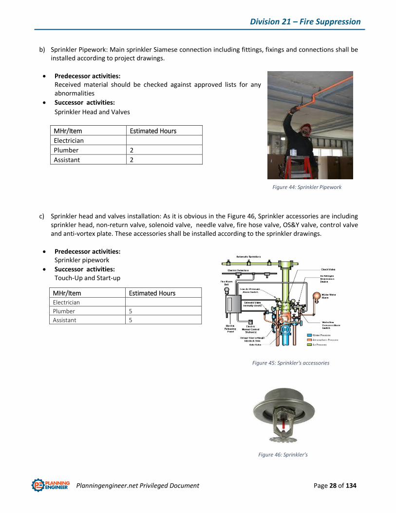
b) Sprinkler Pipework: Main sprinkler Siamese connection including fittings, fixings and connections shall be installed according to project drawings.
Predecessor activities: Received material should be checked against approved lists for any abnormalities
Successor activities:
Sprinkler Head and Valves
c) Sprinkler head and valves installation: As it is obvious in the Figure 46, Sprinkler accessories are including sprinkler head, non-return valve, solenoid valve, needle valve, fire hose valve, OS&Y valve, control valve and anti-vortex plate. These accessories shall be installed according to the sprinkler drawings.
Predecessor activities: Sprinkler pipework
Successor activities: Touch-Up and Start-up
MHr/Item Estimated Hours
Electrician
Plumber 2
Assistant 2
MHr/Item Estimated Hours
Electrician
Plumber 5
Assistant 5
Figure 44: Sprinkler Pipework
Figure 45: Sprinkler's accessories
Figure 46: Sprinkler’s Head

Planningengineer.net Privileged Document Page 29 of 134
Division 21 – Fire Suppression
Fire hose reel Installation:
Fire hose reel equipment is a high-pressure hose that carries water or other fire retardant to a fire to extinguish
it. Outdoors, it attaches either to a fire engine or a fire hydrant. Indoors, it can permanently attach to a building's
standpipe or plumbing system.
a) Fire hose reel Pipework: Including connection including fittings, fixings and connections shall be installed according to project drawings.
Predecessor activities: Received material should be checked against approved lists for any abnormalities
Successor activities: Location and mounting
MHr/Item Estimated Hours
Electrician
Plumber 4
Assistant 4
b) Location and mounting: Each hose reel shall be located in a readily accessible position and its location shall be clearly indicated. They shall not be installed in fire-isolated exits unless approval is obtained from the Regulatory Authority.
Predecessor activities: Pipe work
Successor activities: Connect the stop cock to water supply
MHr/Item Estimated Hours
Electrician
Plumber .5
Assistant .5
Figure 47: Fire hose reel
Figure 48: Pipe work
Planningengineer.net Privileged Document Page 30 of 134
Division 21 – Fire Suppression
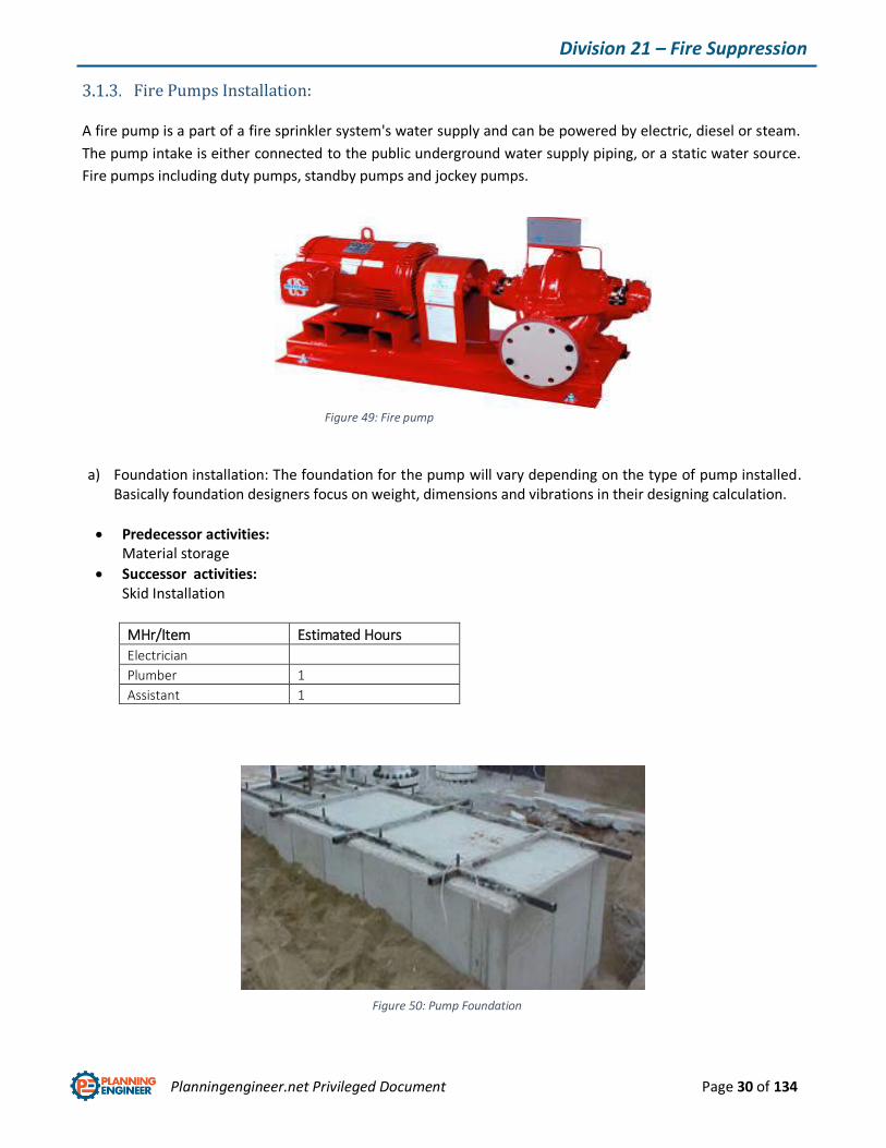
Fire Pumps Installation:
A fire pump is a part of a fire sprinkler system's water supply and can be powered by electric, diesel or steam.
The pump intake is either connected to the public underground water supply piping, or a static water source.
Fire pumps including duty pumps, standby pumps and jockey pumps.
a) Foundation installation: The foundation for the pump will vary depending on the type of pump installed.
Basically foundation designers focus on weight, dimensions and vibrations in their designing calculation.
Predecessor activities: Material storage
Successor activities: Skid Installation
MHr/Item Estimated Hours
Electrician
Plumber 1
Assistant 1
Figure 49: Fire pump
Figure 50: Pump Foundation
Planningengineer.net Privileged Document Page 31 of 134
Division 21 – Fire Suppression
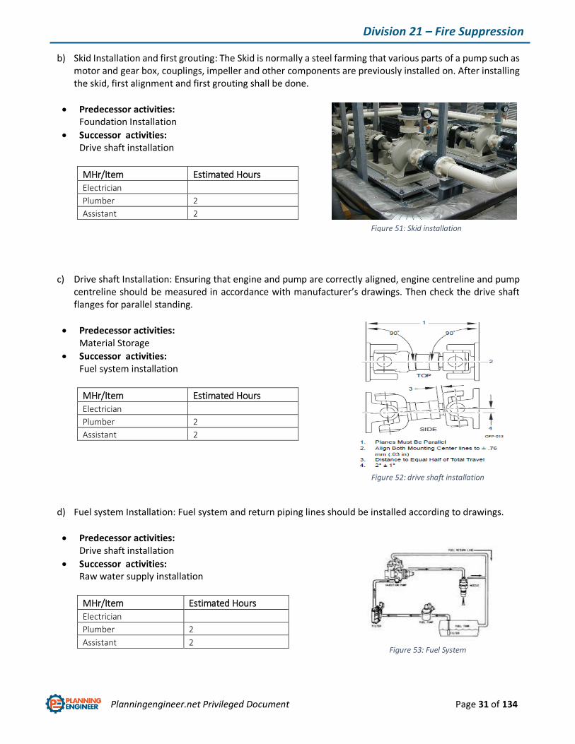
b) Skid Installation and first grouting: The Skid is normally a steel farming that various parts of a pump such as motor and gear box, couplings, impeller and other components are previously installed on. After installing the skid, first alignment and first grouting shall be done.
Predecessor activities: Foundation Installation
Successor activities: Drive shaft installation
MHr/Item Estimated Hours
Electrician
Plumber 2
Assistant 2
c) Drive shaft Installation: Ensuring that engine and pump are correctly aligned, engine centreline and pump
centreline should be measured in accordance with manufacturer’s drawings. Then check the drive shaft flanges for parallel standing.
Predecessor activities: Material Storage
Successor activities: Fuel system installation
MHr/Item Estimated Hours
Electrician
Plumber 2
Assistant 2
d) Fuel system Installation: Fuel system and return piping lines should be installed according to drawings.
Predecessor activities: Drive shaft installation
Successor activities: Raw water supply installation
MHr/Item Estimated Hours
Electrician
Plumber 2
Assistant 2
Figure 52: drive shaft installation
Figure 53: Fuel System
Figure 51: Skid installation and first grouting

Planningengineer.net Privileged Document Page 32 of 134
Division 21 – Fire Suppression
e) Raw water supply system Installation: Raw water circulate through the system cools and engine which must be immediately available when the engine started.
Predecessor activities: Fuel system installation
Successor activities: Signal control installation
MHr/Item Estimated Hours
Electrician
Plumber 2
Assistant 2
f) Signal control Installation: The connection between the controller wires and terminal blocks which is named
by signal control system shall be properly installed.
Predecessor activities: Row water system installation
Successor activities: Energize and start-up
MHr/Item Estimated Hours
Electrician 2
Plumber
Assistant 2
Figure 54: Row water flow diagram
Figure 55: Signal control system
Planningengineer.net Privileged Document Page 33 of 134
Division 21 – Fire Suppression
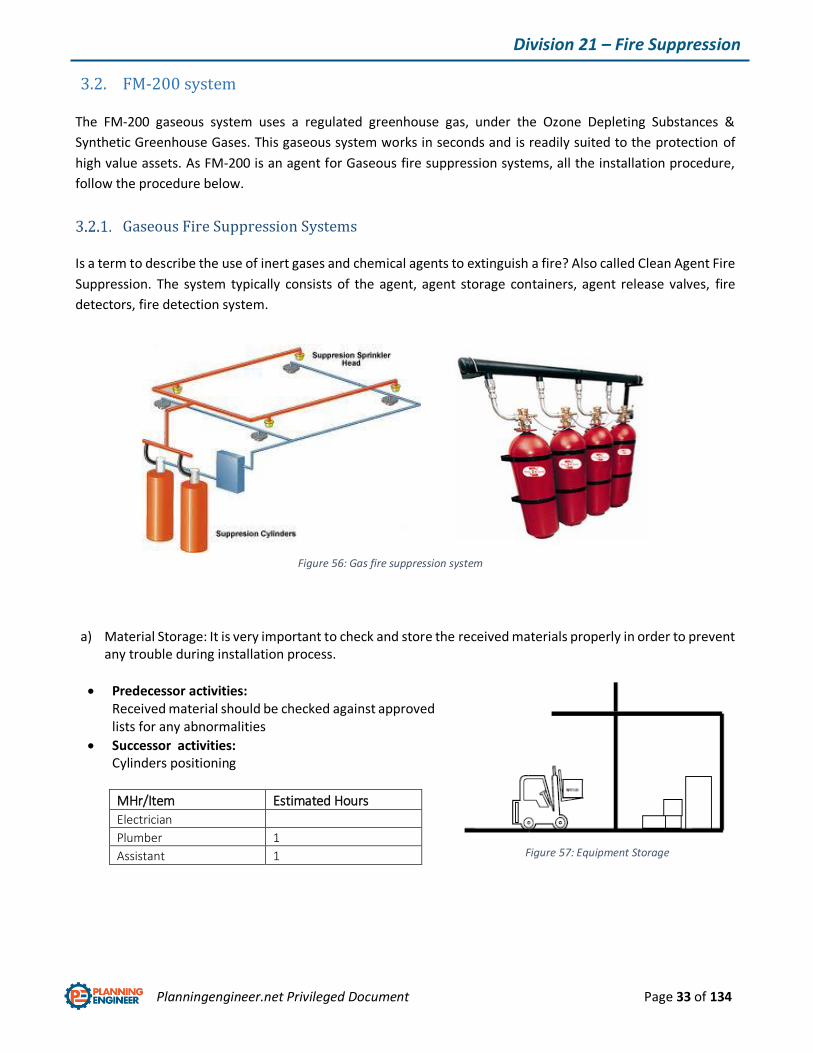
3.2. FM-200 system
The FM-200 gaseous system uses a regulated greenhouse gas, under the Ozone Depleting Substances &
Synthetic Greenhouse Gases. This gaseous system works in seconds and is readily suited to the protection of
high value assets. As FM-200 is an agent for Gaseous fire suppression systems, all the installation procedure,
follow the procedure below.
Gaseous Fire Suppression Systems
Is a term to describe the use of inert gases and chemical agents to extinguish a fire? Also called Clean Agent Fire
Suppression. The system typically consists of the agent, agent storage containers, agent release valves, fire
detectors, fire detection system.
a) Material Storage: It is very important to check and store the received materials properly in order to prevent any trouble during installation process.
Predecessor activities: Received material should be checked against approved lists for any abnormalities
Successor activities: Cylinders positioning
MHr/Item Estimated Hours
Electrician
Plumber 1
Assistant 1
Figure 56: Gas fire suppression system
Figure 57: Equipment Storage
Planningengineer.net Privileged Document Page 34 of 134
Division 21 – Fire Suppression
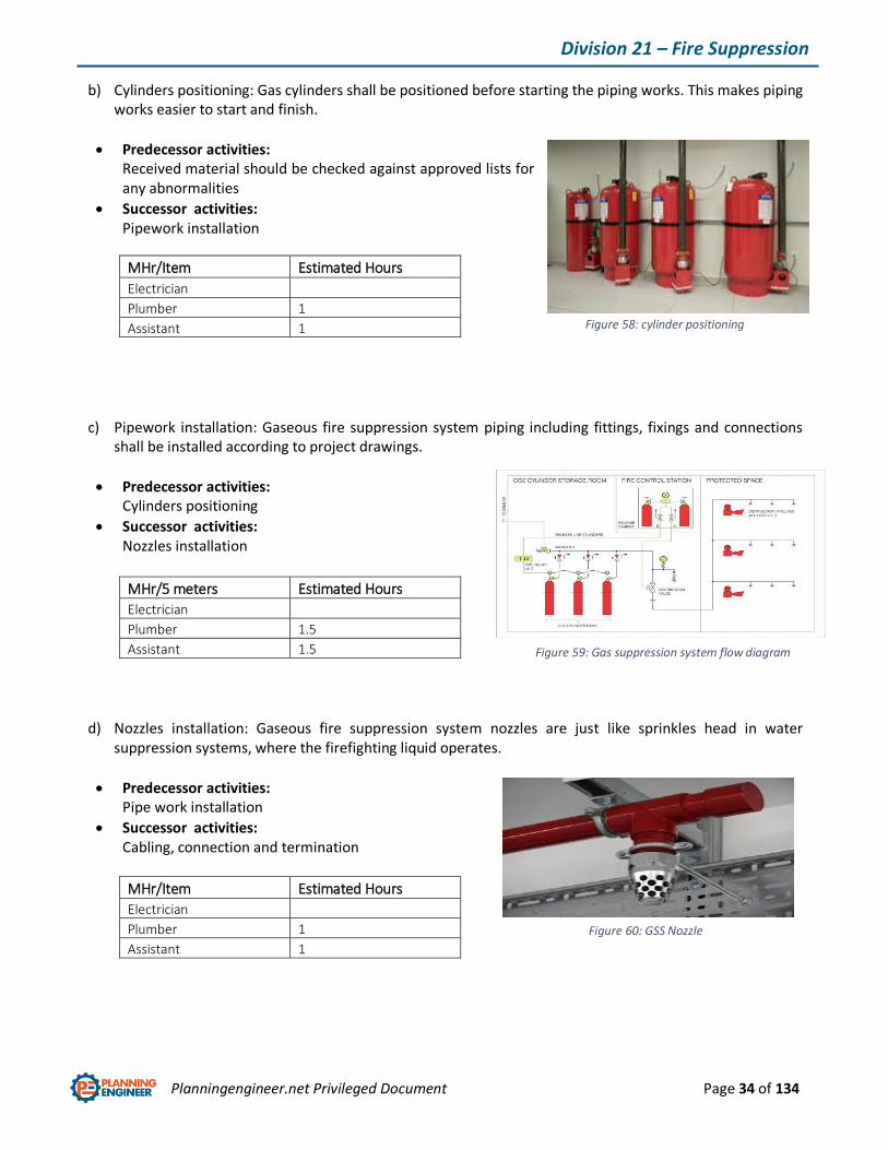
b) Cylinders positioning: Gas cylinders shall be positioned before starting the piping works. This makes piping works easier to start and finish.
Predecessor activities: Received material should be checked against approved lists for any abnormalities
Successor activities: Pipework installation
MHr/Item Estimated Hours
Electrician
Plumber 1
Assistant 1
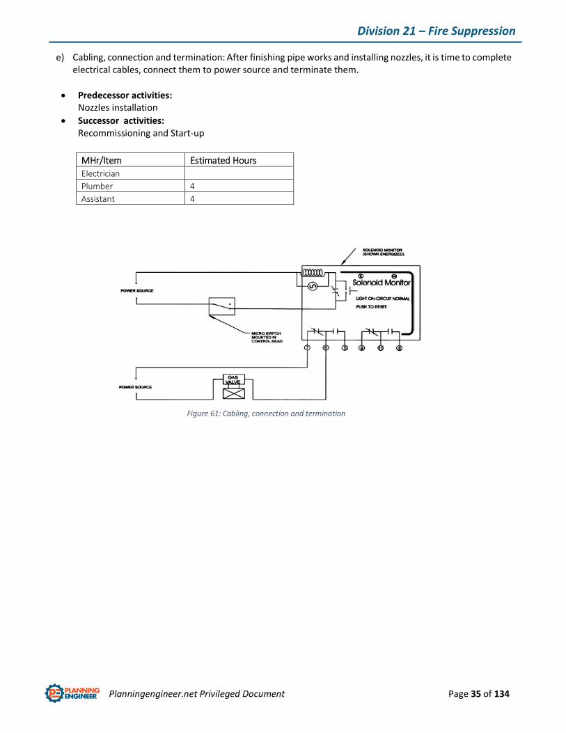
c) Pipework installation: Gaseous fire suppression system piping including fittings, fixings and connections shall be installed according to project drawings.
Predecessor activities: Cylinders positioning
Successor activities: Nozzles installation
MHr/5 meters Estimated Hours
Electrician
Plumber 1.5
Assistant 1.5
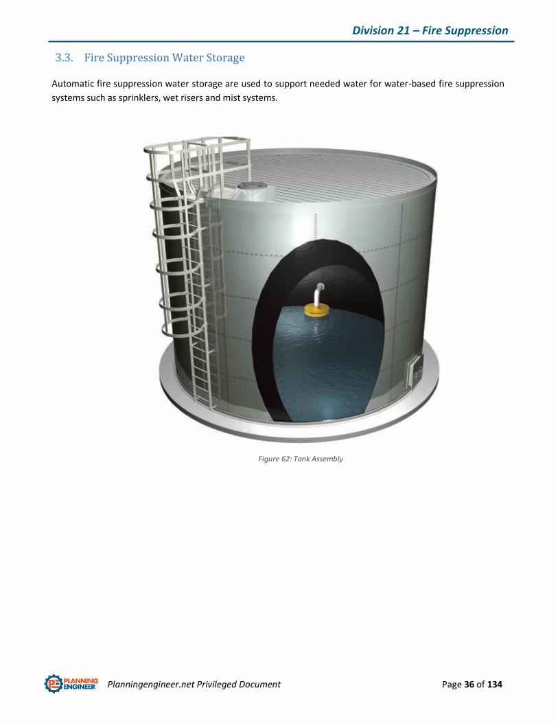
d) Nozzles installation: Gaseous fire suppression system nozzles are just like sprinkles head in water suppression systems, where the firefighting liquid operates.
Predecessor activities: Pipe work installation
Successor activities: Cabling, connection and termination
MHr/Item Estimated Hours
Electrician
Plumber 1
Assistant 1
Figure 59: Gas suppression system flow diagram
Figure 58: cylinder positioning
Figure 60: GSS Nozzle
Planningengineer.net Privileged Document Page 35 of 134
Division 21 – Fire Suppression
e) Cabling, connection and termination: After finishing pipe works and installing nozzles, it is time to complete electrical cables, connect them to power source and terminate them.
Predecessor activities: Nozzles installation
Successor activities: Recommissioning and Start-up
MHr/Item Estimated Hours
Electrician
Plumber 4
Assistant 4
Figure 61: Cabling, connection and termination
Planningengineer.net Privileged Document Page 36 of 134
Division 21 – Fire Suppression
3.3. Fire Suppression Water Storage
Automatic fire suppression water storage are used to support needed water for water-based fire suppression
systems such as sprinklers, wet risers and mist systems.
Figure 62: Tank Assembly
Planningengineer.net Privileged Document Page 37 of 134
Division 21 – Fire Suppression
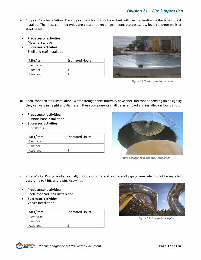
a) Support Base installation: The support base for the sprinkler tank will vary depending on the type of tank installed. The most common types are circular or rectangular concrete bases, low level concrete walls or steel beams.
Predecessor activities: Material storage
Successor activities: Shell and roof installation
MHr/Item Estimated Hours
Electrician
Plumber 3
Assistant 3
b) Shell, roof and Stair installation: Water storage tanks normally have shell and roof depending on designing they can vary in height and diameter. These components shall be assembled and installed on foundation.
Predecessor activities: Support base installation
Successor activities: Pipe works
MHr/Item Estimated Hours
Electrician
Plumber 5
Assistant 5
c) Pipe Works: Piping works normally include GRP, lateral and overall piping lines which shall be installed according to P&ID and piping drawings.
Predecessor activities: Shell, roof and Stair installation
Successor activities: Valves installation
MHr/Item Estimated Hours
Electrician
Plumber 5
Assistant 5
Figure 63: Tank support/foundation
Figure 64: shell, roof and stair installation
Figure 65: Storage tank piping
Planningengineer.net Privileged Document Page 38 of 134
Division 21 – Fire Suppression
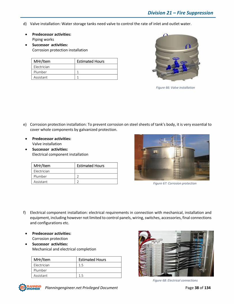
d) Valve installation: Water storage tanks need valve to control the rate of inlet and outlet water.
Predecessor activities: Piping works
Successor activities: Corrosion protection installation
MHr/Item Estimated Hours
Electrician
Plumber 1
Assistant 1
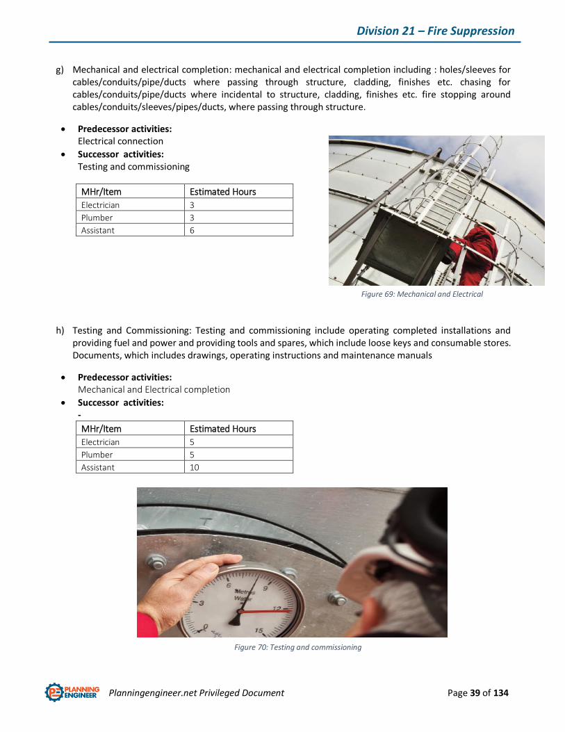
e) Corrosion protection installation: To prevent corrosion on steel sheets of tank’s body, it is very essential to cover whole components by galvanized protection.
Predecessor activities: Valve installation
Successor activities: Electrical component installation
MHr/Item Estimated Hours
Electrician
Plumber 2
Assistant 2
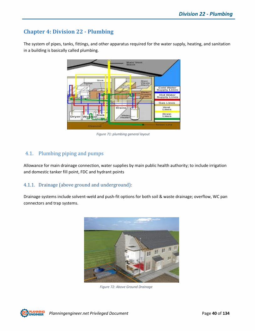
f) Electrical component installation: electrical requirements in connection with mechanical, installation and equipment, including however not limited to control panels, wiring, switches, accessories, final connections and configurations etc.
Predecessor activities: Corrosion protection
Successor activities: Mechanical and electrical completion
MHr/Item Estimated Hours
Electrician 1.5
Plumber
Assistant 1.5
Figure 66: Valve installation
Figure 67: Corrosion protection
Figure 68: Electrical connections
Planningengineer.net Privileged Document Page 39 of 134
Division 21 – Fire Suppression
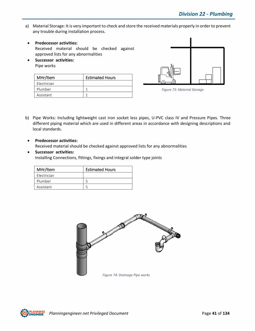
g) Mechanical and electrical completion: mechanical and electrical completion including : holes/sleeves for
cables/conduits/pipe/ducts where passing through structure, cladding, finishes etc. chasing for cables/conduits/pipe/ducts where incidental to structure, cladding, finishes etc. fire stopping around cables/conduits/sleeves/pipes/ducts, where passing through structure.
Predecessor activities: Electrical connection
Successor activities: Testing and commissioning
MHr/Item Estimated Hours
Electrician 3
Plumber 3
Assistant 6
h) Testing and Commissioning: Testing and commissioning include operating completed installations and providing fuel and power and providing tools and spares, which include loose keys and consumable stores. Documents, which includes drawings, operating instructions and maintenance manuals
Predecessor activities: Mechanical and Electrical completion
Successor activities: -
MHr/Item Estimated Hours
Electrician 5
Plumber 5
Assistant 10
Figure 69: Mechanical and Electrical completion
Figure 70: Testing and commissioning
Planningengineer.net Privileged Document Page 40 of 134
Division 22 - Plumbing
Chapter 4: Division 22 - Plumbing
The system of pipes, tanks, fittings, and other apparatus required for the water supply, heating, and sanitation
in a building is basically called plumbing.
4.1. Plumbing piping and pumps
Allowance for main drainage connection, water supplies by main public health authority; to include irrigation
and domestic tanker fill point, FDC and hydrant points
Drainage (above ground and underground):
Drainage systems include solvent-weld and push-fit options for both soil & waste drainage; overflow, WC pan
connectors and trap systems.
Figure 71: plumbing general layout
Figure 72: Above Ground Drainage
Planningengineer.net Privileged Document Page 41 of 134
Division 22 - Plumbing
a) Material Storage: It is very important to check and store the received materials properly in order to prevent any trouble during installation process.
Predecessor activities: Received material should be checked against approved lists for any abnormalities
Successor activities: Pipe works
MHr/Item Estimated Hours
Electrician
Plumber 1
Assistant 1
b) Pipe Works: Including lightweight cast iron socket less pipes, U-PVC class IV and Pressure Pipes. Three different piping material which are used in different areas in accordance with designing descriptions and local standards.
Predecessor activities: Received material should be checked against approved lists for any abnormalities
Successor activities: Installing Connections, fittings, fixings and integral solder type joints
MHr/Item Estimated Hours
Electrician
Plumber 5
Assistant 5
Figure 73: Material Storage
Figure 74: Drainage Pipe works

Planningengineer.net Privileged Document Page 42 of 134
Division 22 - Plumbing
c) Installing Connections, fittings, fixings and integral solder type joints: Cutting pipes in accordance with drawings and connect to other parts by fittings, connections and joints.
Predecessor activities: Pipe Works
Successor activities: Sealing and usage
MHr/Item Estimated Hours
Electrician
Plumber 3
Assistant 3
Figure 75: Installing Connections, Expansion joints and etc.

Planningengineer.net Privileged Document Page 43 of 134
Division 22 - Plumbing
Water Services (Cold, Hot, Grey and Irrigation):
Generally including drinking water and wastewater services to residential, commercial, and industrial sectors of
the economy. Cold and Hot water services are provided for drinking usage, in the other hand, grey water and
irrigation water are provided by wastewater.
a) Material Storage: It is very important to check and store the received materials properly in order to prevent any trouble during installation process.
Predecessor activities: Received material should be checked against approved lists for any abnormalities
Successor activities: Pipe installation
MHr/Item Estimated Hours
Electrician
Plumber 1
Assistant 1
Figure 78: Material Storage
Figure 77: Grey and Irrigation water service Figure 77: Cold and Hot water service
Planningengineer.net Privileged Document Page 44 of 134
Division 22 - Plumbing
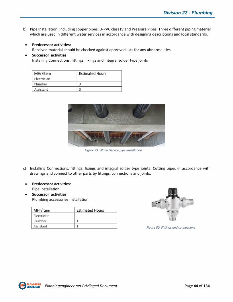
b) Pipe Installation: Including copper pipes, U-PVC class IV and Pressure Pipes. Three different piping material which are used in different water services in accordance with designing descriptions and local standards.
Predecessor activities: Received material should be checked against approved lists for any abnormalities
Successor activities: Installing Connections, fittings, fixings and integral solder type joints
c) Installing Connections, fittings, fixings and integral solder type joints: Cutting pipes in accordance with drawings and connect to other parts by fittings, connections and joints.
Predecessor activities: Pipe installation
Successor activities: Plumbing accessories Installation
MHr/Item Estimated Hours
Electrician
Plumber 1
Assistant 1
MHr/Item Estimated Hours
Electrician
Plumber 3
Assistant 3
Figure 79: Water Service pipe installation
Figure 80: Fittings and connections

Planningengineer.net Privileged Document Page 45 of 134
Division 22 - Plumbing
Water Heater
Is an appliance consisting of a gas or electric heating unit under a tank in which water is heated and stored.
a) WATER HEATER installation: This water heater must be installed vertically upright with the water, gas and power connections on the underside, pointing toward the ground. The back of the water heater can be either against a wall or supported by a frame. The water heater must be secured to the wall or frame using suitable mounting screws, two each at the top and bottom of the unit.
Predecessor activities: Received material should be checked against approved lists for any abnormalities
Successor activities: Pipe works and connections
MHr/Item Estimated Hours
Electrician
Plumber 2
Assistant 2
Figure 81: Water heater lay out
Figure 82: Installing Water heater
Planningengineer.net Privileged Document Page 46 of 134
Division 22 - Plumbing
b) Pipe works and connections: Including lightweight cast iron socket less pipes, U-PVC class IV and Pressure Pipes. Three different piping material which are used in different areas in accordance with designing descriptions and local standards
Predecessor activities: Water heater installation
Successor activities: FROST PROTECTION
MHr/Item Estimated Hours
Electrician
Plumber 3
Assistant 3
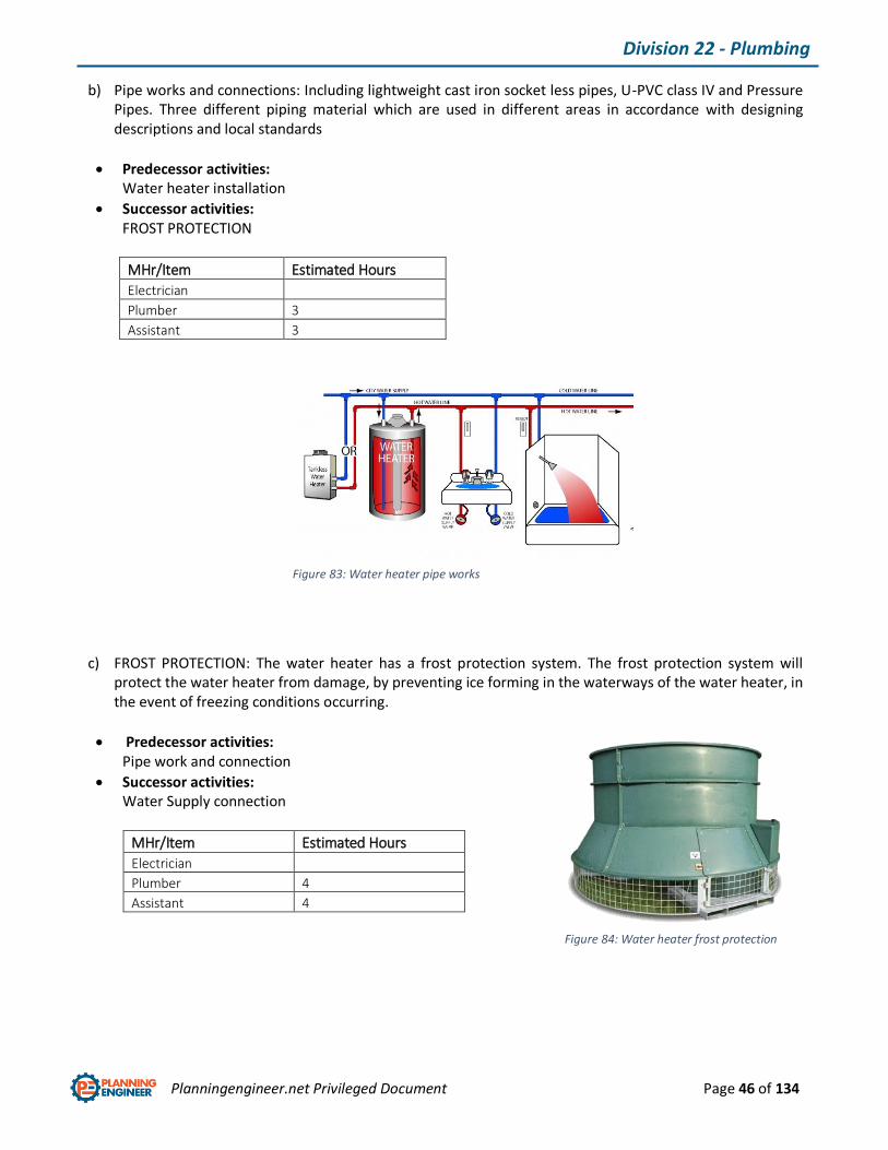
c) FROST PROTECTION: The water heater has a frost protection system. The frost protection system will protect the water heater from damage, by preventing ice forming in the waterways of the water heater, in the event of freezing conditions occurring.
Predecessor activities: Pipe work and connection
Successor activities: Water Supply connection
MHr/Item Estimated Hours
Electrician
Plumber 4
Assistant 4
Figure 83: Water heater pipe works
Figure 84: Water heater frost protection
Planningengineer.net Privileged Document Page 47 of 134
Division 22 - Plumbing
Plumbing accessories Installation:
Including Valves (Shut-off, OS&Y, non-return and check, float, gate, commissioning set), Strainers, pressure
gauge and cock, Shock absorber, water meter and automatic trap primers. Installation procedure for all of above
mentioned plumbing accessories are pretty much the same, but for more illumination, each one of them are
described as below :
Shut-off Valves: A valve that cuts off water to one or more fixtures, allowing repairs without shutting off the
supply system for the entire house.
OS&Y Valves: Outside Screw and Yoke (OS & Y) which Used mainly in fire prevention.
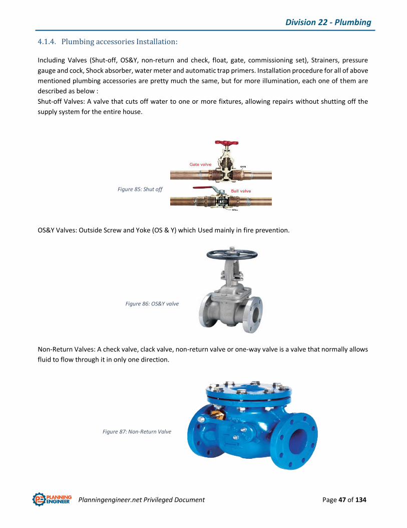
Non-Return Valves: A check valve, clack valve, non-return valve or one-way valve is a valve that normally allows
fluid to flow through it in only one direction.
Figure 85: Shut off valves
Figure 86: OS&Y valve
Figure 87: Non-Return Valve
Planningengineer.net Privileged Document Page 48 of 134
Division 22 - Plumbing
Float Valves: Valve float is an adverse condition which occurs when the poppet valves on an internal combustion
engine valve train do not remain in contact with the camshaft lobe during the valve closure phase of the cam
lobe profile. This reduces engine efficiency and performance and potentially increases engine emissions.
Commissioning set: A set of balancing valves can ensure the correct distribution of water.
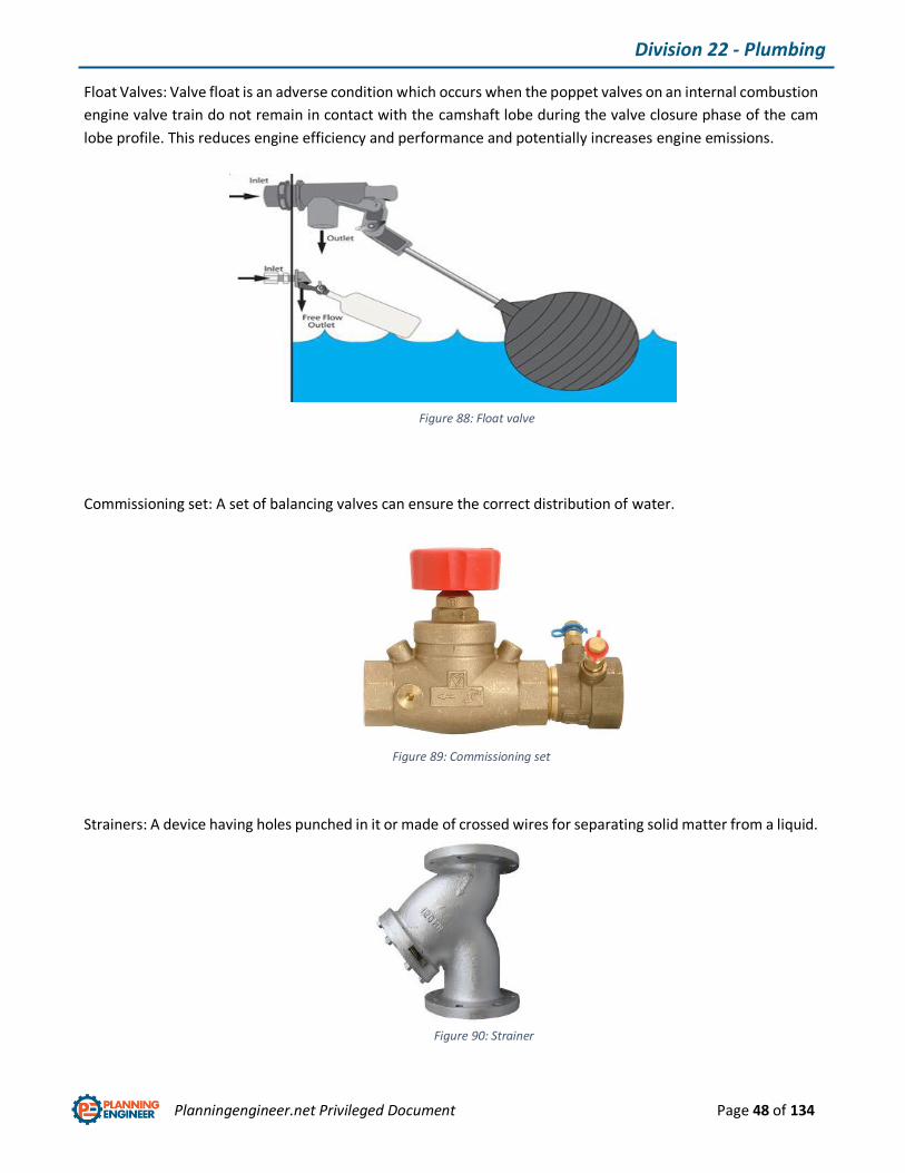
Strainers: A device having holes punched in it or made of crossed wires for separating solid matter from a liquid.
Figure 88: Float valve
Figure 89: Commissioning set
Figure 90: Strainer
Planningengineer.net Privileged Document Page 49 of 134
Division 22 - Plumbing
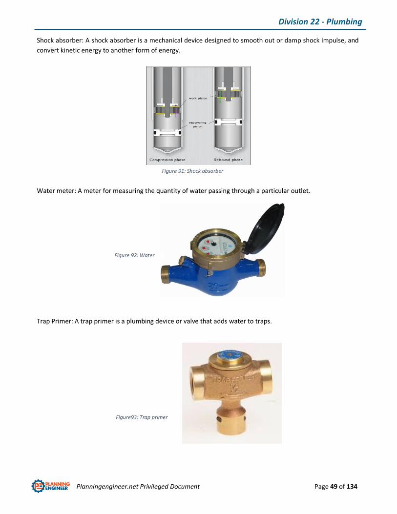
Shock absorber: A shock absorber is a mechanical device designed to smooth out or damp shock impulse, and
convert kinetic energy to another form of energy.
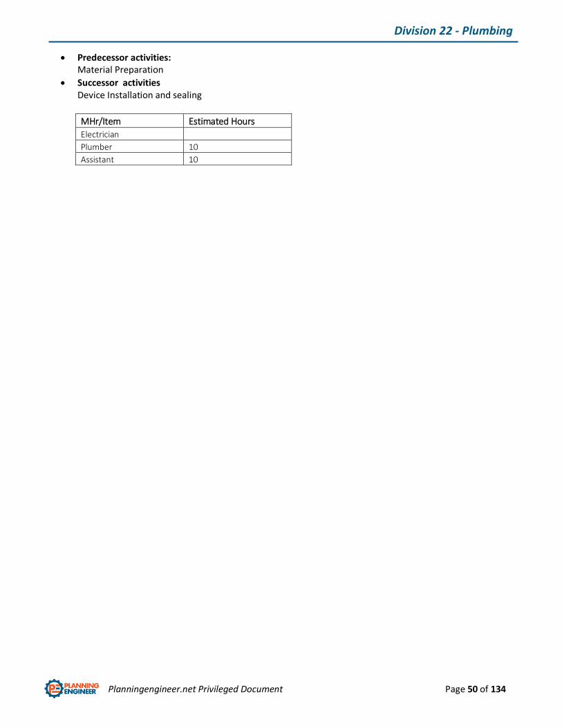
Water meter: A meter for measuring the quantity of water passing through a particular outlet.
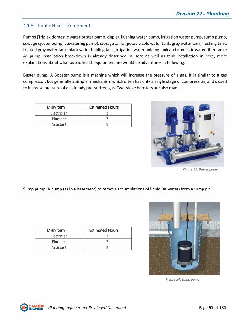
Trap Primer: A trap primer is a plumbing device or valve that adds water to traps.
Figure 91: Shock absorber
Figure 92: Water meter
Figure93: Trap primer
Planningengineer.net Privileged Document Page 50 of 134
Division 22 - Plumbing
Predecessor activities: Material Preparation
Successor activities Device Installation and sealing
MHr/Item Estimated Hours
Electrician
Plumber 10
Assistant 10
Planningengineer.net Privileged Document Page 51 of 134
Division 22 - Plumbing
Public Health Equipment
Pumps (Triplex domestic water buster pump, duplex flushing water pump, irrigation water pump, sump pump,
sewage ejector pump, dewatering pump), storage tanks (potable cold water tank, grey water tank, flushing tank,
treated gray water tank, black water holding tank, irrigation water holding tank and domestic water filter tank):
As pump installation breakdown is already described in Here as well as tank installation in here, more
explanations about what public health equipment are would be adventures in following:
Buster pump: A Booster pump is a machine which will increase the pressure of a gas. It is similar to a gas
compressor, but generally a simpler mechanism which often has only a single stage of compression, and s used
to increase pressure of an already pressurized gas. Two-stage boosters are also made.
Sump pump: A pump (as in a basement) to remove accumulations of liquid (as water) from a sump pit.
MHr/Item Estimated Hours
Electrician 2
Plumber 7
Assistant 9
MHr/Item Estimated Hours
Electrician 2
Plumber 7
Assistant 9
Figure 93: Buster pump
Figure 94: Sump pump
Planningengineer.net Privileged Document Page 52 of 134
Division 22 - Plumbing
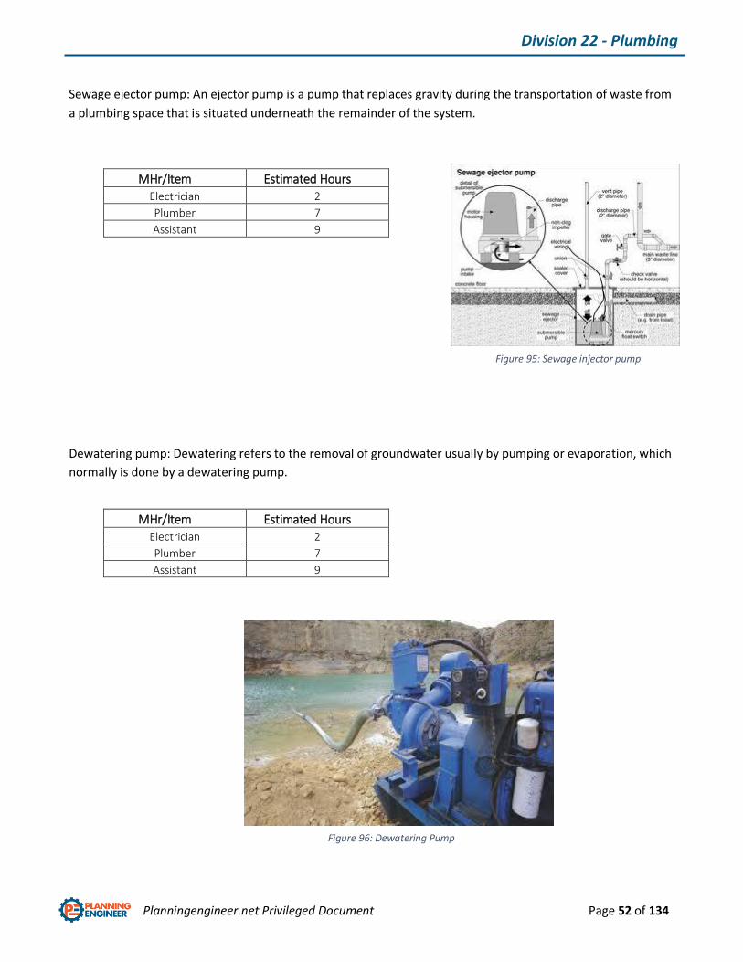
Sewage ejector pump: An ejector pump is a pump that replaces gravity during the transportation of waste from
a plumbing space that is situated underneath the remainder of the system.
Dewatering pump: Dewatering refers to the removal of groundwater usually by pumping or evaporation, which
normally is done by a dewatering pump.
MHr/Item Estimated Hours
Electrician 2
Plumber 7
Assistant 9
MHr/Item Estimated Hours
Electrician 2
Plumber 7
Assistant 9
Figure 95: Sewage injector pump
Figure 96: Dewatering Pump
Planningengineer.net Privileged Document Page 53 of 134
Division 22 - Plumbing
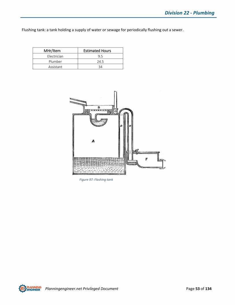
Flushing tank: a tank holding a supply of water or sewage for periodically flushing out a sewer.
MHr/Item Estimated Hours
Electrician 9.5
Plumber 24.5
Assistant 34
Figure 97: Flashing tank
Planningengineer.net Privileged Document Page 54 of 134
Division 22 - Plumbing
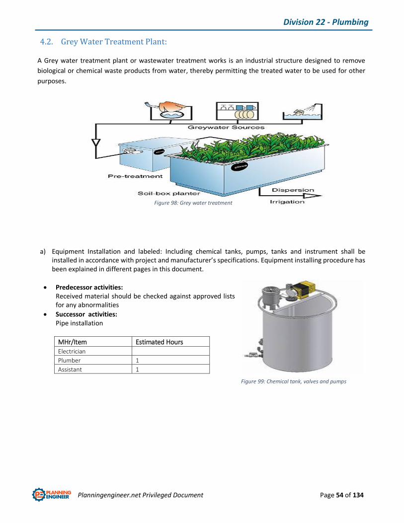
4.2. Grey Water Treatment Plant:
A Grey water treatment plant or wastewater treatment works is an industrial structure designed to remove
biological or chemical waste products from water, thereby permitting the treated water to be used for other
purposes.
a) Equipment Installation and labeled: Including chemical tanks, pumps, tanks and instrument shall be installed in accordance with project and manufacturer’s specifications. Equipment installing procedure has been explained in different pages in this document.
Predecessor activities: Received material should be checked against approved lists for any abnormalities
Successor activities: Pipe installation
MHr/Item Estimated Hours
Electrician
Plumber 1
Assistant 1
Figure 98: Grey water treatment plant
Figure 99: Chemical tank, valves and pumps

Planningengineer.net Privileged Document Page 55 of 134
Division 22 - Plumbing
b) Pipe works: Including pipe installation, fittings and connections to the equipment.
Predecessor activities: Equipment installation
Successor activities: Electrical equipment installation
MHr/5 meter Estimated Hours
Electrician
Plumber 4
Assistant 4
c) Electrical equipment Installation and labeled: Including motors, push-button stations, isolating switches, limit and level switches.
Predecessor activities: Pipe works
Successor activities: Touch-up and start-up
MHr/Item Estimated Hours
Electrician 3
Plumber
Assistant 3
Figure 100: Piping and connections
Figure 101: Electrical Works

Planningengineer.net Privileged Document Page 56 of 134
Division 22 - Plumbing
4.3. RO Plant
Reverse osmosis (RO) is a water purification technology that uses a semipermeable membrane. This membrane
technology is not properly a filtration method. In reverse osmosis, an applied pressure is used to overcome
osmotic pressure, a colligative property that is driven by chemical potential, a thermodynamic parameter.
a) Equipment Installation and labeled: Including water tanks, pumps, instrument shall be installed in accordance with project and manufacturer’s specifications. Equipment installing procedure has been explained in different pages in this document.
Predecessor activities: Received material should be checked against approved lists for any abnormalities
Successor activities: Pipe installation
MHr/Item Estimated Hours
Electrician
Plumber 1
Assistant 1
Figure 102: RO plant
Figure 103: RO pumps and instrumentation
Planningengineer.net Privileged Document Page 57 of 134
Division 22 - Plumbing
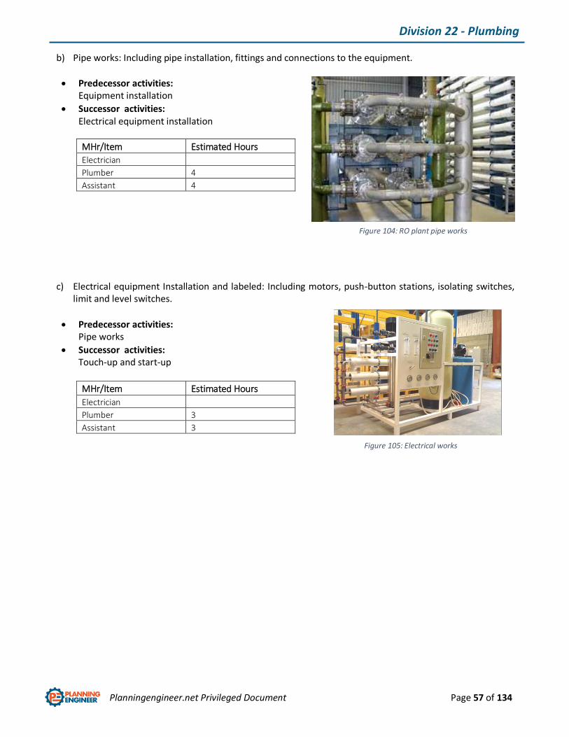
b) Pipe works: Including pipe installation, fittings and connections to the equipment.
Predecessor activities: Equipment installation
Successor activities: Electrical equipment installation
MHr/Item Estimated Hours
Electrician
Plumber 4
Assistant 4
c) Electrical equipment Installation and labeled: Including motors, push-button stations, isolating switches, limit and level switches.
Predecessor activities: Pipe works
Successor activities: Touch-up and start-up
MHr/Item Estimated Hours
Electrician
Plumber 3
Assistant 3
Figure 104: RO plant pipe works
Figure 105: Electrical works
Planningengineer.net Privileged Document Page 58 of 134
Division 22 - Plumbing
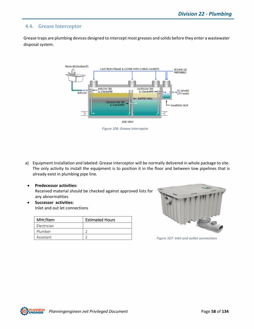
4.4. Grease Interceptor
Grease traps are plumbing devices designed to intercept most greases and solids before they enter a wastewater
disposal system.
a) Equipment Installation and labeled: Grease interceptor will be normally delivered in whole package to site. The only activity to install the equipment is to position it in the floor and between tow pipelines that is already exist in plumbing pipe line.
Predecessor activities: Received material should be checked against approved lists for any abnormalities
Successor activities: Inlet and out let connections
MHr/Item Estimated Hours
Electrician
Plumber 2
Assistant 2
Figure 106: Grease interceptor
Figure 107: Inlet and outlet connections

Planningengineer.net Privileged Document Page 59 of 134
Division 22 - Plumbing
4.5. Plumbing Fixtures
Plumbing fixtures are set of fixtures for the distribution and use of water in a building including sanitary fittings,
wash hand basin, WC suite and water closet.
a) Equipment Installation and labeled: The only activity to install the equipment is to position them and then connect them using waste and tapes.
Predecessor activities: Received material should be checked against approved lists for any abnormalities
Successor activities: Cleaning and using
MHr/Item Estimated Hours
Electrician
Plumber 2
Assistant 2
Figure 108: Plumbing Fixtures
Planningengineer.net Privileged Document Page 60 of 134
Division 22 - Plumbing
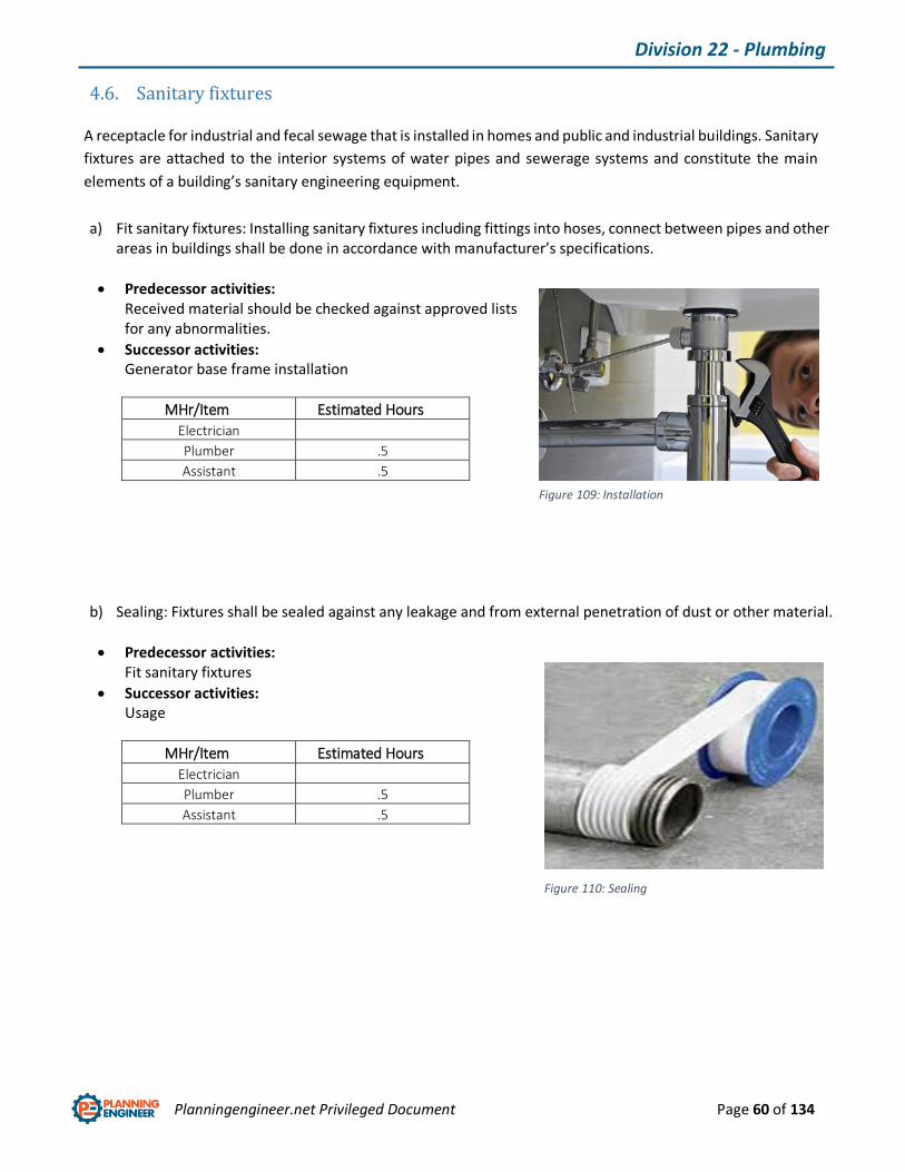
4.6. Sanitary fixtures
A receptacle for industrial and fecal sewage that is installed in homes and public and industrial buildings. Sanitary
fixtures are attached to the interior systems of water pipes and sewerage systems and constitute the main
elements of a building’s sanitary engineering equipment.
a) Fit sanitary fixtures: Installing sanitary fixtures including fittings into hoses, connect between pipes and other areas in buildings shall be done in accordance with manufacturer’s specifications.
Predecessor activities: Received material should be checked against approved lists for any abnormalities.
Successor activities: Generator base frame installation
MHr/Item Estimated Hours
Electrician
Plumber .5
Assistant .5
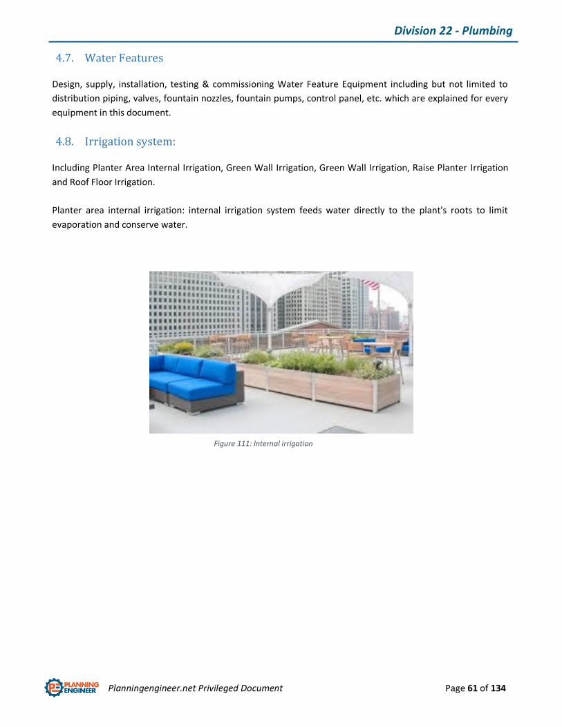
b) Sealing: Fixtures shall be sealed against any leakage and from external penetration of dust or other material.
Predecessor activities: Fit sanitary fixtures
Successor activities: Usage
MHr/Item Estimated Hours
Electrician
Plumber .5
Assistant .5
Figure 109: Installation
Figure 110: Sealing
Planningengineer.net Privileged Document Page 61 of 134
Division 22 - Plumbing
4.7. Water Features
Design, supply, installation, testing & commissioning Water Feature Equipment including but not limited to
distribution piping, valves, fountain nozzles, fountain pumps, control panel, etc. which are explained for every
equipment in this document.
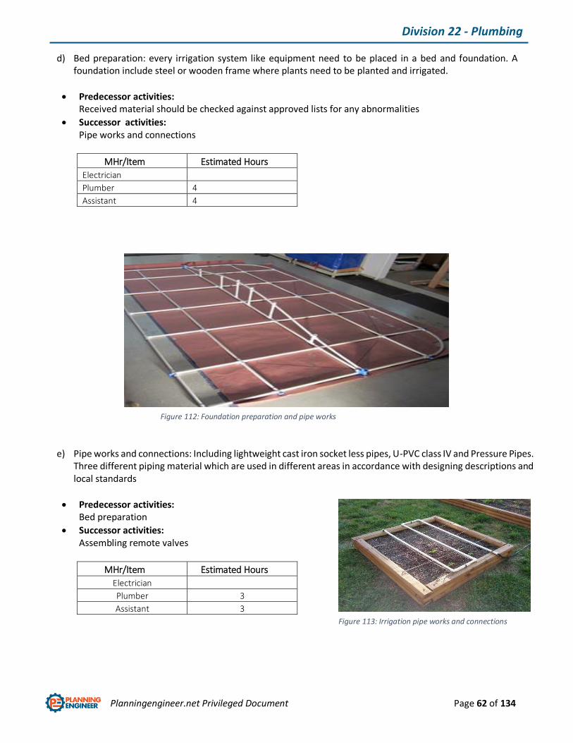
4.8. Irrigation system:
Including Planter Area Internal Irrigation, Green Wall Irrigation, Green Wall Irrigation, Raise Planter Irrigation
and Roof Floor Irrigation.
Planter area internal irrigation: internal irrigation system feeds water directly to the plant's roots to limit
evaporation and conserve water.
Figure 111: Internal irrigation
Planningengineer.net Privileged Document Page 62 of 134
Division 22 - Plumbing
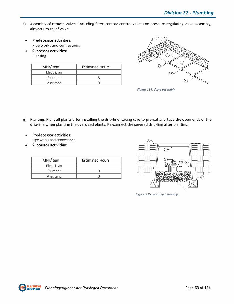
d) Bed preparation: every irrigation system like equipment need to be placed in a bed and foundation. A foundation include steel or wooden frame where plants need to be planted and irrigated.
Predecessor activities: Received material should be checked against approved lists for any abnormalities
Successor activities: Pipe works and connections
MHr/Item Estimated Hours
Electrician
Plumber 4
Assistant 4
e) Pipe works and connections: Including lightweight cast iron socket less pipes, U-PVC class IV and Pressure Pipes. Three different piping material which are used in different areas in accordance with designing descriptions and local standards
Predecessor activities: Bed preparation
Successor activities: Assembling remote valves
MHr/Item Estimated Hours
Electrician
Plumber 3
Assistant 3
Figure 112: Foundation preparation and pipe works
Figure 113: Irrigation pipe works and connections
Planningengineer.net Privileged Document Page 63 of 134
Division 22 - Plumbing
f) Assembly of remote valves: Including filter, remote control valve and pressure regulating valve assembly, air vacuum relief valve.
Predecessor activities: Pipe works and connections
Successor activities: Planting
MHr/Item Estimated Hours
Electrician
Plumber 3
Assistant 3
g) Planting: Plant all plants after installing the drip-line, taking care to pre-cut and tape the open ends of the drip-line when planting the oversized plants. Re-connect the severed drip-line after planting.
Predecessor activities: Pipe works and connections
Successor activities: -
MHr/Item Estimated Hours
Electrician
Plumber 3
Assistant 3
Figure 114: Valve assembly
Figure 115: Planting assembly

Planningengineer.net Privileged Document Page 64 of 134
Division 22 - Plumbing
Green wall internal irrigation: A green wall is comprised of plants grown in supported vertical and inclined
systems.
Raise planter irrigation: A raised bed planter includes a planter body having four bed walls with four corners that
define a planting area for holding soil and cultivating plants therein.
Figure 116: Green Wall internal irrigation
Figure 117: Raise planter irrigation

Planningengineer.net Privileged Document Page 65 of 134
Division 22 - Plumbing
Roof floor irrigation: A built-in, nonstructural portion of a roof system. Conventional irrigation system commonly
uses pressure to deliver water and distributes it through plants.
Figure 118: Roof irrigation

Planningengineer.net Privileged Document Page 66 of 134
Division 23 – Heating Ventilation & Air Conditioning
Chapter 5: Division 23 - Heating Ventilation and Air Conditioning
HVAC is the technology of indoor and vehicular environmental comfort. HVAC system design is a sub discipline
of mechanical engineering, based on the principles of thermodynamics, fluid mechanics, and heat transfer.
5.1. Facility fuel system (Generator)
A dynamic or similar machine for converting mechanical energy into electricity and produce power from fuel for
system. There are various fuel systems such as fuel pumps, generators and etc.
Figure 119: HVAC configuration
Figure 120: Generator layout

Planningengineer.net Privileged Document Page 67 of 134
Division 23 – Heating Ventilation & Air Conditioning
c) Set drive unit, switching gear unit, fuel oil transfer pump and tank, control panel in base frame: Normally A generator is delivered to site whilst all mentioned generating parts are assembled in steel base frame. But it is very important to check the received generating set against manufacturer’s drawings.
d) Foundation preparation: Just like every other equipment, generators need steel structure or concrete floor/foundation to be installed.
Predecessor activities: Received material should be checked against approved lists for any abnormalities
Successor activities: Generator base frame installation
MHr/Item Estimated Hours
Electrician
Plumber 2
Assistant 2
Figure 121: Set of generating machine is assembled in base frame
Figure 122: Generator foundation

Planningengineer.net Privileged Document Page 68 of 134
Division 23 – Heating Ventilation & Air Conditioning
e) Generator set installation: Generator base frame shall be lifted to the foundation area and be placed in accordance with drawings. After positioning, generator foundation pockets shall be grouted.
Predecessor activities: Generator foundation preparation
Successor activities: Pipe works
MHr/Item Estimated Hours
Electrician
Plumber 2
Assistant 2
f) Generator exhaust pipe installation: After installing and grouting the generator set, exhaust pipe shall be installed by using a flexible joint to the generator vent. As it is shown in picture, there is exhaust silencer installed in line with pipe lines to reduce vibration noises.
Predecessor activities: Generator set installation
Successor activities: Fuel supply installation
MHr/Item Estimated Hours
Electrician
Plumber 5
Assistant 5
g) Fuel supply installation: A dependable fuel supply system must assure instant availability of fuel to facilitate starting and to keep the engine operating. This requires, at a minimum, a small day tank (usually incorporated into the generating set base frame - called a base tank) located close to the generating set.
Predecessor activities: Generator exhaust pipe assembly installation
Successor activities: Fuel Pipe works
MHr/Item Estimated Hours
Electrician
Plumber 3
Assistant 3
Figure 123: Generator set installation
Figure 124: Generator exhaust pipe assembly
Figure 125: Fuel tank installation
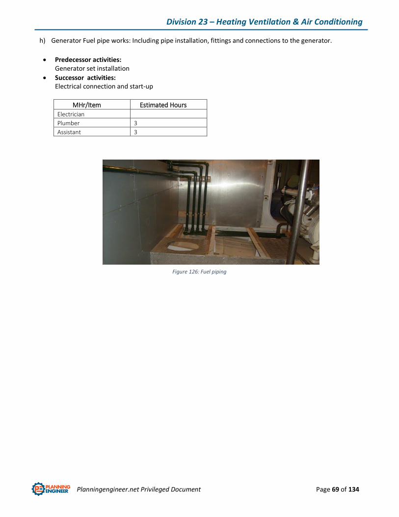
Planningengineer.net Privileged Document Page 69 of 134
Division 23 – Heating Ventilation & Air Conditioning
h) Generator Fuel pipe works: Including pipe installation, fittings and connections to the generator.
Predecessor activities: Generator set installation
Successor activities: Electrical connection and start-up
MHr/Item Estimated Hours
Electrician
Plumber 3
Assistant 3
Figure 126: Fuel piping

Planningengineer.net Privileged Document Page 70 of 134
Division 23 – Heating Ventilation & Air Conditioning
5.2. HVAC piping and pumps
Including condensate pipework, insulation, underfloor radiant cooling, valve, strainer, pressure gauge, flow
switch, water meter and air separator installation.
5.3. Condensate pipework
No single set of recommendations can cover the layout of condensate pipework. Much depends on the
application pressure, the steam trap characteristics, the position of the condensate return main relative to
the plant, and the pressure in the condensate return main. But in order to install pipes, basic regulations shall
be considered as described in this document earlier.
Figure 127: HVAC piping and pumps
Figure 128: Condensate pipe works
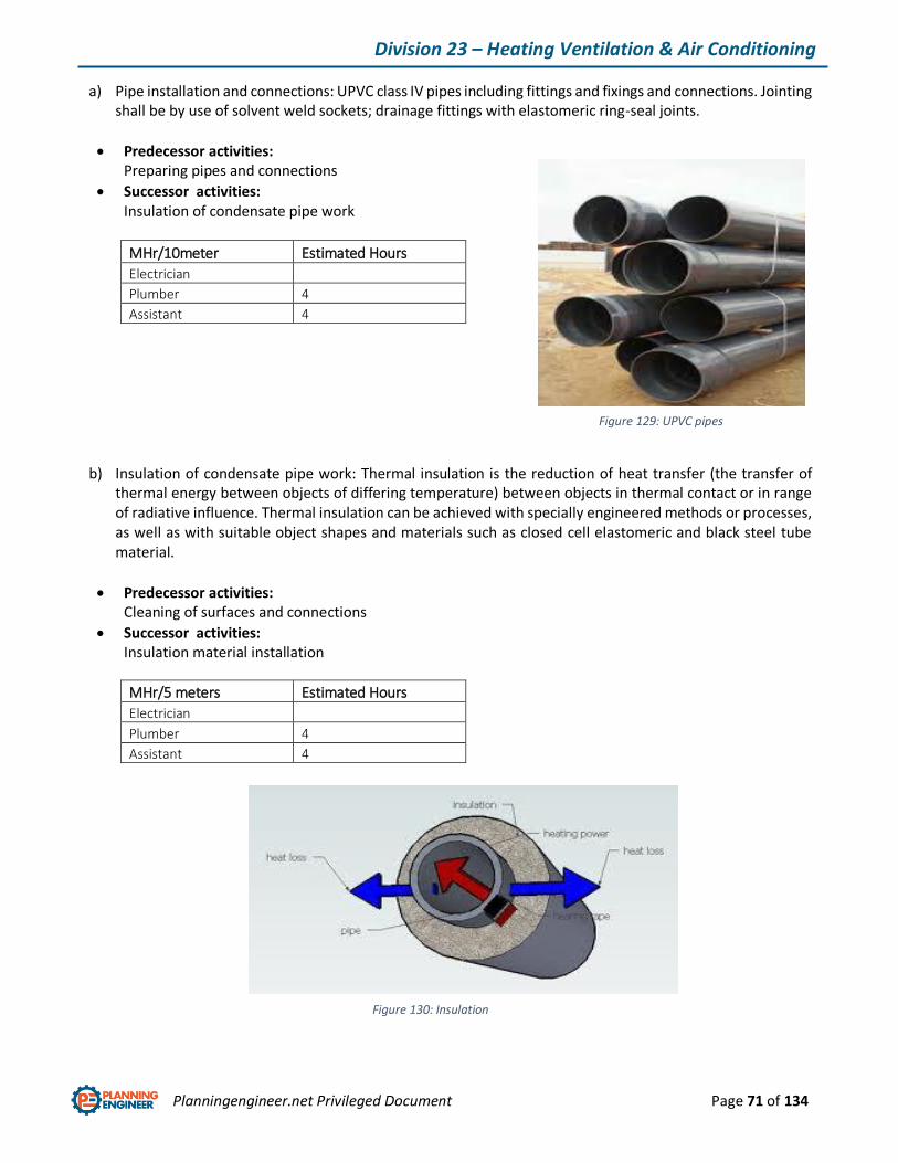
Planningengineer.net Privileged Document Page 71 of 134
Division 23 – Heating Ventilation & Air Conditioning
a) Pipe installation and connections: UPVC class IV pipes including fittings and fixings and connections. Jointing shall be by use of solvent weld sockets; drainage fittings with elastomeric ring-seal joints.
Predecessor activities: Preparing pipes and connections
Successor activities: Insulation of condensate pipe work
MHr/10meter Estimated Hours
Electrician
Plumber 4
Assistant 4
b) Insulation of condensate pipe work: Thermal insulation is the reduction of heat transfer (the transfer of thermal energy between objects of differing temperature) between objects in thermal contact or in range of radiative influence. Thermal insulation can be achieved with specially engineered methods or processes, as well as with suitable object shapes and materials such as closed cell elastomeric and black steel tube material.
Predecessor activities: Cleaning of surfaces and connections
Successor activities: Insulation material installation
MHr/5 meters Estimated Hours
Electrician
Plumber 4
Assistant 4
Figure 129: UPVC pipes
Figure 130: Insulation
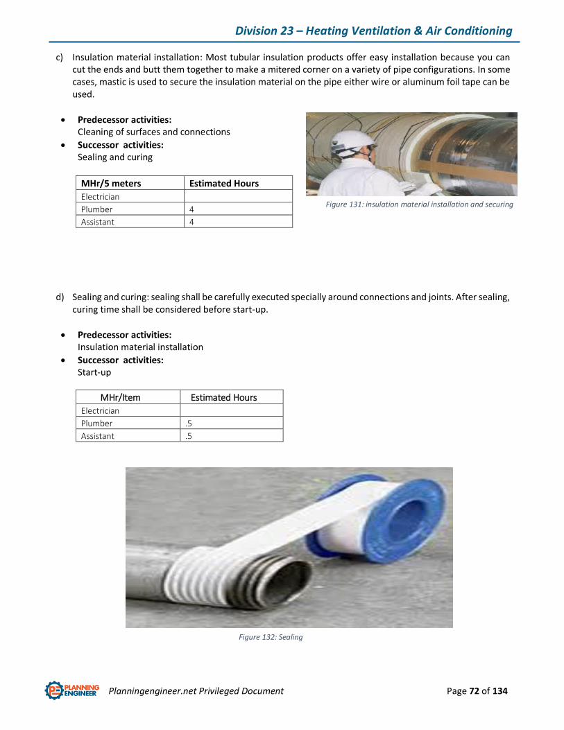
Planningengineer.net Privileged Document Page 72 of 134
Division 23 – Heating Ventilation & Air Conditioning
c) Insulation material installation: Most tubular insulation products offer easy installation because you can cut the ends and butt them together to make a mitered corner on a variety of pipe configurations. In some cases, mastic is used to secure the insulation material on the pipe either wire or aluminum foil tape can be used.
Predecessor activities: Cleaning of surfaces and connections
Successor activities: Sealing and curing
MHr/5 meters Estimated Hours
Electrician
Plumber 4
Assistant 4
d) Sealing and curing: sealing shall be carefully executed specially around connections and joints. After sealing, curing time shall be considered before start-up.
Predecessor activities: Insulation material installation
Successor activities: Start-up
MHr/Item Estimated Hours
Electrician
Plumber .5
Assistant .5
Figure 131: insulation material installation and securing
Figure 132: Sealing
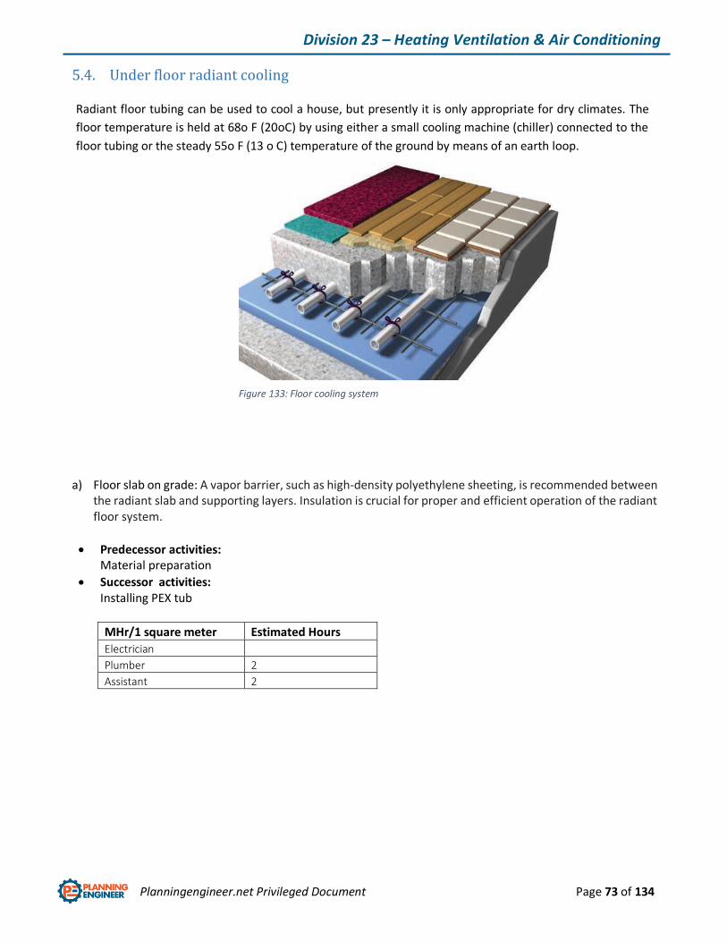
Planningengineer.net Privileged Document Page 73 of 134
Division 23 – Heating Ventilation & Air Conditioning
5.4. Under floor radiant cooling
Radiant floor tubing can be used to cool a house, but presently it is only appropriate for dry climates. The
floor temperature is held at 68o F (20oC) by using either a small cooling machine (chiller) connected to the
floor tubing or the steady 55o F (13 o C) temperature of the ground by means of an earth loop.
a) Floor slab on grade: A vapor barrier, such as high-density polyethylene sheeting, is recommended between the radiant slab and supporting layers. Insulation is crucial for proper and efficient operation of the radiant floor system.
Predecessor activities: Material preparation
Successor activities: Installing PEX tub
MHr/1 square meter Estimated Hours
Electrician
Plumber 2
Assistant 2
Figure 133: Floor cooling system
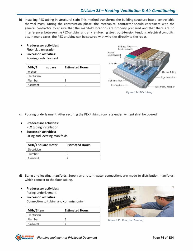
Planningengineer.net Privileged Document Page 74 of 134
Division 23 – Heating Ventilation & Air Conditioning
b) Installing PEX tubing in structural slab: This method transforms the building structure into a controllable thermal mass. During the construction phase, the mechanical contractor should coordinate with the general contractor to ensure that the manifold locations are properly prepared and that there are no interferences between the PEX-a tubing and any reinforcing steel, post-tension tendons, electrical conduits, etc. In many cases, the PEX-a tubing can be secured with wire ties directly to the rebar.
Predecessor activities: Floor slab on grade
Successor activities: Pouring underlayment
MHr/1 square meter
Estimated Hours
Electrician
Plumber 3
Assistant 3
c) Pouring underlayment: After securing the PEX tubing, concrete underlayment shall be poured.
Predecessor activities: PEX tubing installation
Successor activities: Sizing and locating manifolds
MHr/1 square meter Estimated Hours
Electrician
Plumber 2
Assistant 2
d) Sizing and locating manifolds: Supply and return water connections are made to distribution manifolds, which connect to the floor tubing.
Predecessor activities: Poring underlayment
Successor activities: Connection to tubing and commissioning
MHr/5Item Estimated Hours
Electrician
Plumber 1
Assistant 1
Figure 134: PEX tubing installation
Figure 135: Sizing and locating manifolds

Planningengineer.net Privileged Document Page 75 of 134
Division 23 – Heating Ventilation & Air Conditioning
5.5. HVAC Air distribution
Air flow shall be distributed in specific areas by ducting.
Duct Work
A system of ducts used for a particular purpose, as in a ventilation or heating system. Duct is normally made
of hot-dip galvanized steel sheets including fittings and connections with secondary steel support. There are
two types of duct work here: architectural plenum and under floor air plenum. Since metal is a good thermal
conductor, such ducts require thermal insulation, the commonest material for which is glass wool, usually in
roll form (known as ‘wraps’ or ‘wrapped insulation’), wrapped around the outer duct wall.
a) Set mounting rings or supports: mounting rings or supports are steel fabricated rings or frames depends on manufacturer’s standards.
Predecessor activities: Preparing material
Successor activities: Duct installation
MHr/Item Estimated Hours
Electrician
Plumber .5
Assistant .5
Figure 136: Air distribution
Figure 137: Duct support
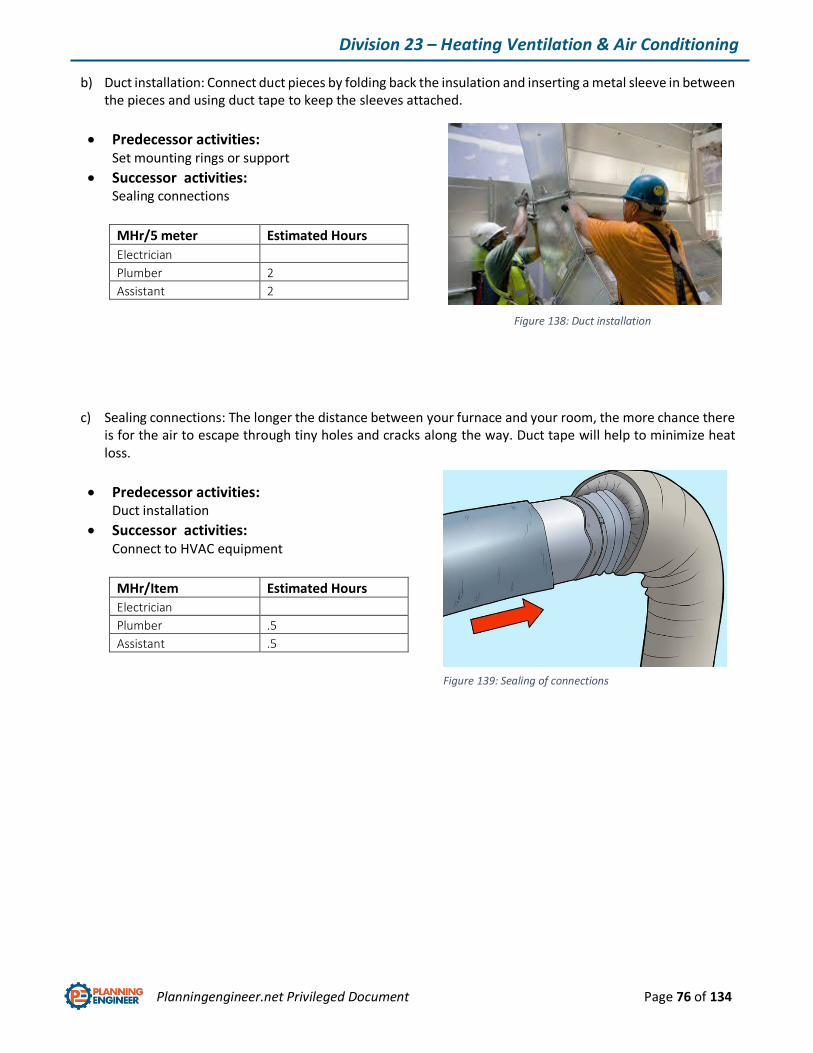
Planningengineer.net Privileged Document Page 76 of 134
Division 23 – Heating Ventilation & Air Conditioning
b) Duct installation: Connect duct pieces by folding back the insulation and inserting a metal sleeve in between the pieces and using duct tape to keep the sleeves attached.
Predecessor activities: Set mounting rings or support
Successor activities: Sealing connections
MHr/5 meter Estimated Hours
Electrician
Plumber 2
Assistant 2
c) Sealing connections: The longer the distance between your furnace and your room, the more chance there is for the air to escape through tiny holes and cracks along the way. Duct tape will help to minimize heat loss.
Predecessor activities: Duct installation
Successor activities: Connect to HVAC equipment
MHr/Item Estimated Hours
Electrician
Plumber .5
Assistant .5
Figure 138: Duct installation
Figure 139: Sealing of connections
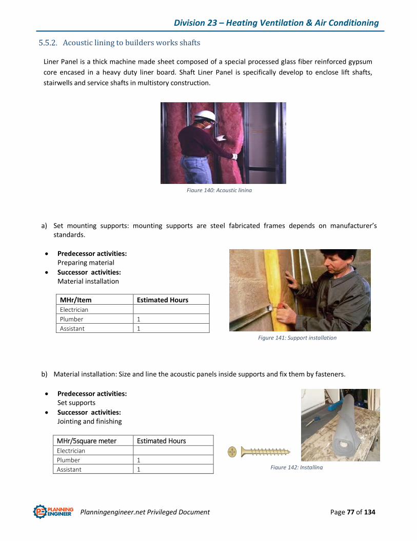
Planningengineer.net Privileged Document Page 77 of 134
Division 23 – Heating Ventilation & Air Conditioning
Acoustic lining to builders works shafts
Liner Panel is a thick machine made sheet composed of a special processed glass fiber reinforced gypsum
core encased in a heavy duty liner board. Shaft Liner Panel is specifically develop to enclose lift shafts,
stairwells and service shafts in multistory construction.
a) Set mounting supports: mounting supports are steel fabricated frames depends on manufacturer’s standards.
Predecessor activities: Preparing material
Successor activities: Material installation
MHr/Item Estimated Hours
Electrician
Plumber 1
Assistant 1
b) Material installation: Size and line the acoustic panels inside supports and fix them by fasteners.
Predecessor activities:
Set supports
Successor activities: Jointing and finishing
MHr/5square meter Estimated Hours
Electrician
Plumber 1
Assistant 1
Figure 140: Acoustic lining
Figure 141: Support installation
Figure 142: Installing material and fasteners
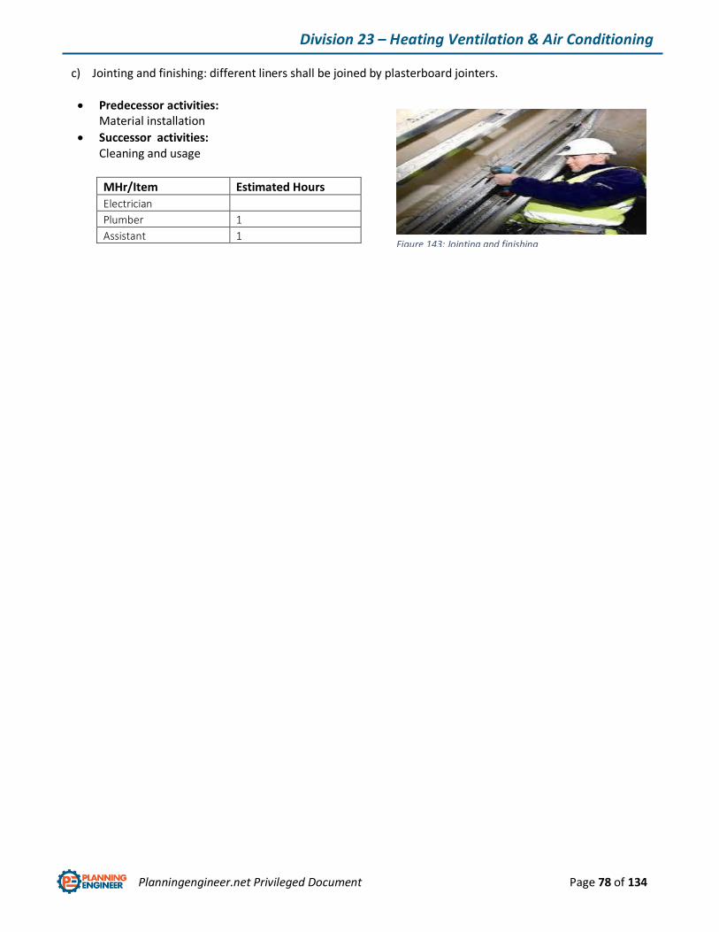
Planningengineer.net Privileged Document Page 78 of 134
Division 23 – Heating Ventilation & Air Conditioning
c) Jointing and finishing: different liners shall be joined by plasterboard jointers.
Predecessor activities: Material installation
Successor activities: Cleaning and usage
MHr/Item Estimated Hours
Electrician
Plumber 1
Assistant 1
Figure 143: Jointing and finishing
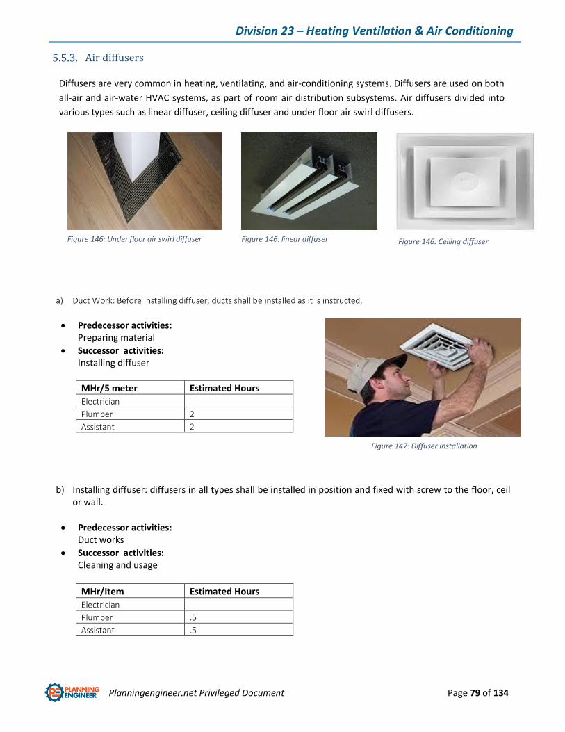
Planningengineer.net Privileged Document Page 79 of 134
Division 23 – Heating Ventilation & Air Conditioning
Air diffusers
Diffusers are very common in heating, ventilating, and air-conditioning systems. Diffusers are used on both
all-air and air-water HVAC systems, as part of room air distribution subsystems. Air diffusers divided into
various types such as linear diffuser, ceiling diffuser and under floor air swirl diffusers.
a) Duct Work: Before installing diffuser, ducts shall be installed as it is instructed.
Predecessor activities: Preparing material
Successor activities: Installing diffuser
MHr/5 meter Estimated Hours
Electrician
Plumber 2
Assistant 2
b) Installing diffuser: diffusers in all types shall be installed in position and fixed with screw to the floor, ceil or wall.
Predecessor activities: Duct works
Successor activities: Cleaning and usage
MHr/Item Estimated Hours
Electrician
Plumber .5
Assistant .5
Figure 146: Under floor air swirl diffuser Figure 146: linear diffuser Figure 146: Ceiling diffuser
Figure 147: Diffuser installation
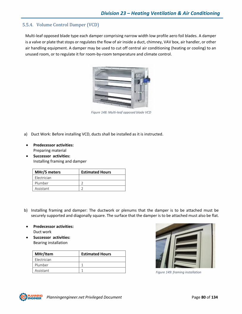
Planningengineer.net Privileged Document Page 80 of 134
Division 23 – Heating Ventilation & Air Conditioning
Volume Control Damper (VCD)
Multi-leaf opposed blade type each damper comprising narrow width low profile aero foil blades. A damper
is a valve or plate that stops or regulates the flow of air inside a duct, chimney, VAV box, air handler, or other
air handling equipment. A damper may be used to cut off central air conditioning (heating or cooling) to an
unused room, or to regulate it for room-by-room temperature and climate control.
a) Duct Work: Before installing VCD, ducts shall be installed as it is instructed.
Predecessor activities: Preparing material
Successor activities: Installing framing and damper
MHr/5 meters Estimated Hours
Electrician
Plumber 2
Assistant 2
b) Installing framing and damper: The ductwork or plenums that the damper is to be attached must be securely supported and diagonally square. The surface that the damper is to be attached must also be flat.
Predecessor activities: Duct work
Successor activities: Bearing installation
MHr/Item Estimated Hours
Electrician
Plumber 1
Assistant 1
Figure 148: Multi-leaf opposed blade VCD
Figure 149: framing installation
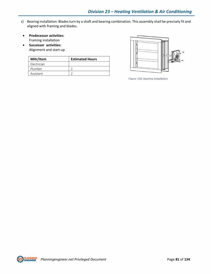
Planningengineer.net Privileged Document Page 81 of 134
Division 23 – Heating Ventilation & Air Conditioning
c) Bearing installation: Blades turn by a shaft and bearing combination. This assembly shall be precisely fit and aligned with framing and blades.
Predecessor activities: Framing installation
Successor activities: Alignment and start-up
MHr/Item Estimated Hours
Electrician
Plumber 2
Assistant 2
Figure 150: bearing installation

Planningengineer.net Privileged Document Page 82 of 134
Division 23 – Heating Ventilation & Air Conditioning
Fire/Smoke Damper (FSD/FD)
Multi-leaf opposed blade type; each damper comprising narrow width low profile aero foil blades.
Fire/smoke dampers are similar to fire dampers in fire resistance rating, and also prevent the spread of smoke
inside the ducts. When a rise in temperature occurs, the fire damper closes, usually activated by a thermal
element which melts at temperatures higher than ambient but low enough to indicate the presence of a fire,
allowing springs to close the damper blades.
a) Installation: installation process is completely the same as VCD installation. The last step would be installation of actuator and electric wiring.
Predecessor activities: Preparing material
Successor activities: Actuator installing and electric connection
MHr/Item Estimated Hours
Electrician
Plumber 1
Assistant 1
Figure 151: FSD/FD
Figure 152: Actuator installation
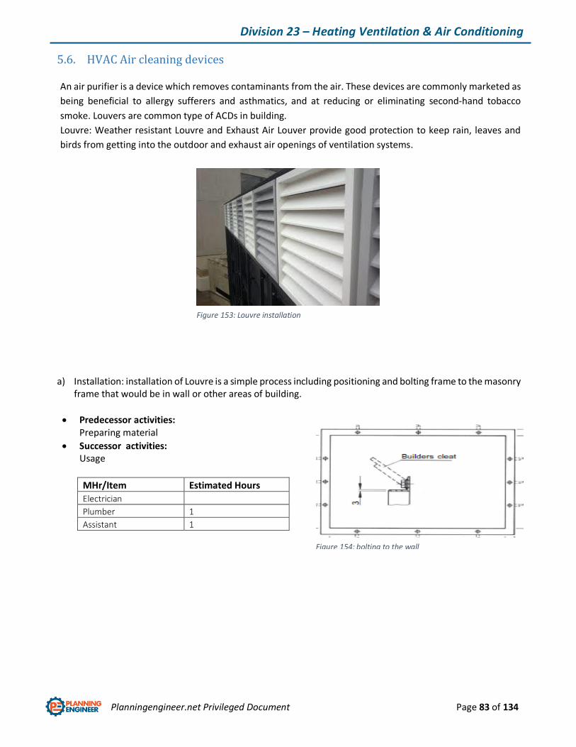
Planningengineer.net Privileged Document Page 83 of 134
Division 23 – Heating Ventilation & Air Conditioning
5.6. HVAC Air cleaning devices
An air purifier is a device which removes contaminants from the air. These devices are commonly marketed as
being beneficial to allergy sufferers and asthmatics, and at reducing or eliminating second-hand tobacco
smoke. Louvers are common type of ACDs in building.
Louvre: Weather resistant Louvre and Exhaust Air Louver provide good protection to keep rain, leaves and
birds from getting into the outdoor and exhaust air openings of ventilation systems.
a) Installation: installation of Louvre is a simple process including positioning and bolting frame to the masonry frame that would be in wall or other areas of building.
Predecessor activities: Preparing material
Successor activities: Usage
MHr/Item Estimated Hours
Electrician
Plumber 1
Assistant 1
Figure 153: Louvre installation
Figure 154: bolting to the wall
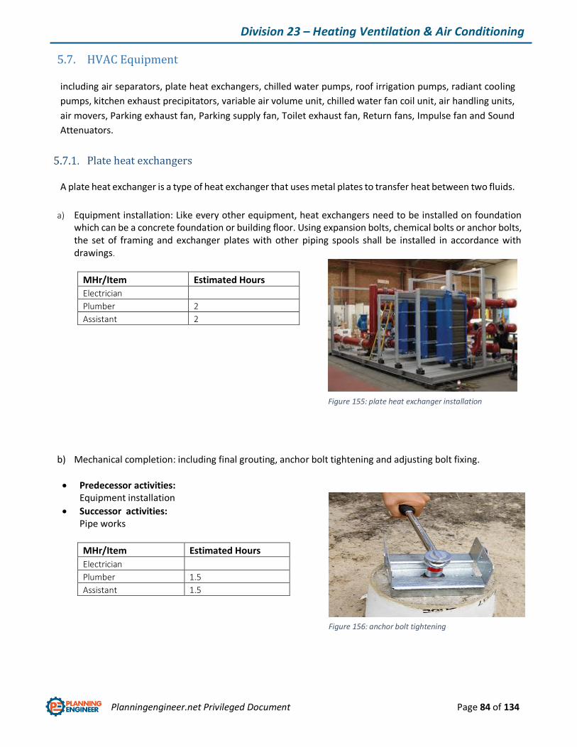
Planningengineer.net Privileged Document Page 84 of 134
Division 23 – Heating Ventilation & Air Conditioning
5.7. HVAC Equipment
including air separators, plate heat exchangers, chilled water pumps, roof irrigation pumps, radiant cooling
pumps, kitchen exhaust precipitators, variable air volume unit, chilled water fan coil unit, air handling units,
air movers, Parking exhaust fan, Parking supply fan, Toilet exhaust fan, Return fans, Impulse fan and Sound
Attenuators.
Plate heat exchangers
A plate heat exchanger is a type of heat exchanger that uses metal plates to transfer heat between two fluids.
a) Equipment installation: Like every other equipment, heat exchangers need to be installed on foundation which can be a concrete foundation or building floor. Using expansion bolts, chemical bolts or anchor bolts, the set of framing and exchanger plates with other piping spools shall be installed in accordance with drawings.
MHr/Item Estimated Hours
Electrician
Plumber 2
Assistant 2
b) Mechanical completion: including final grouting, anchor bolt tightening and adjusting bolt fixing.
Predecessor activities: Equipment installation
Successor activities: Pipe works
MHr/Item Estimated Hours
Electrician
Plumber 1.5
Assistant 1.5
Figure 155: plate heat exchanger installation
Figure 156: anchor bolt tightening

Planningengineer.net Privileged Document Page 85 of 134
Division 23 – Heating Ventilation & Air Conditioning
c) Pipe works: connecting to piping system and to other processing utilities, inlet and outlet parts of plate heat exchangers shall be connected to pipe lines.
Predecessor activities: Mechanical completion
Successor activities: Testing and commissioning
MHr/5 meters Estimated Hours
Electrician
Plumber 3
Assistant 3
Figure 157: Pipe works
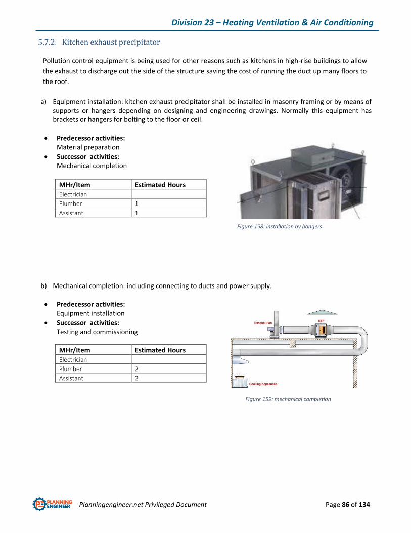
Planningengineer.net Privileged Document Page 86 of 134
Division 23 – Heating Ventilation & Air Conditioning
Kitchen exhaust precipitator
Pollution control equipment is being used for other reasons such as kitchens in high-rise buildings to allow
the exhaust to discharge out the side of the structure saving the cost of running the duct up many floors to
the roof.
a) Equipment installation: kitchen exhaust precipitator shall be installed in masonry framing or by means of supports or hangers depending on designing and engineering drawings. Normally this equipment has brackets or hangers for bolting to the floor or ceil.
Predecessor activities: Material preparation
Successor activities: Mechanical completion
MHr/Item Estimated Hours
Electrician
Plumber 1
Assistant 1
b) Mechanical completion: including connecting to ducts and power supply.
Predecessor activities: Equipment installation
Successor activities: Testing and commissioning
MHr/Item Estimated Hours
Electrician
Plumber 2
Assistant 2
Figure 158: installation by hangers
Figure 159: mechanical completion
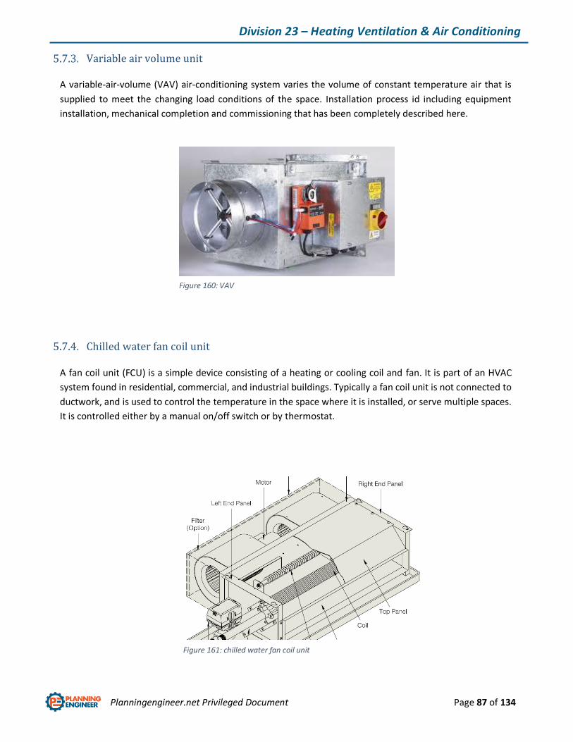
Planningengineer.net Privileged Document Page 87 of 134
Division 23 – Heating Ventilation & Air Conditioning
Variable air volume unit
A variable-air-volume (VAV) air-conditioning system varies the volume of constant temperature air that is
supplied to meet the changing load conditions of the space. Installation process id including equipment
installation, mechanical completion and commissioning that has been completely described here.
Chilled water fan coil unit
A fan coil unit (FCU) is a simple device consisting of a heating or cooling coil and fan. It is part of an HVAC
system found in residential, commercial, and industrial buildings. Typically a fan coil unit is not connected to
ductwork, and is used to control the temperature in the space where it is installed, or serve multiple spaces.
It is controlled either by a manual on/off switch or by thermostat.
Figure 160: VAV
Figure 161: chilled water fan coil unit
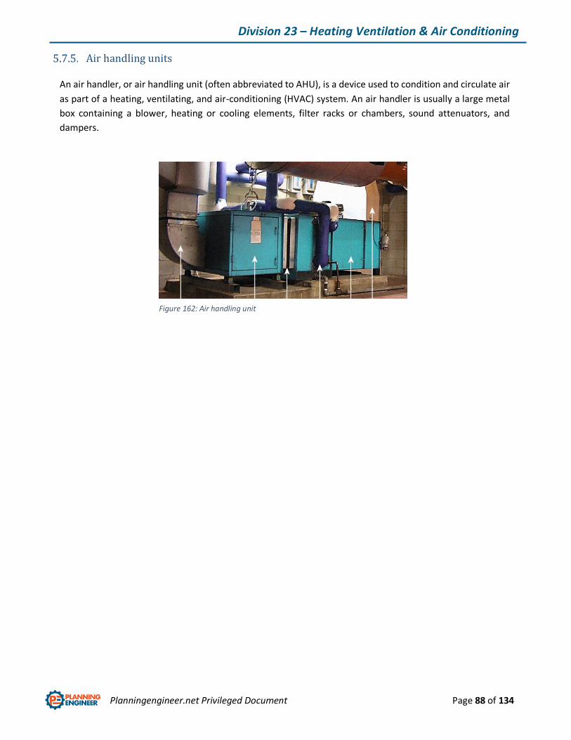
Planningengineer.net Privileged Document Page 88 of 134
Division 23 – Heating Ventilation & Air Conditioning
Air handling units
An air handler, or air handling unit (often abbreviated to AHU), is a device used to condition and circulate air
as part of a heating, ventilating, and air-conditioning (HVAC) system. An air handler is usually a large metal
box containing a blower, heating or cooling elements, filter racks or chambers, sound attenuators, and
dampers.
Figure 162: Air handling unit
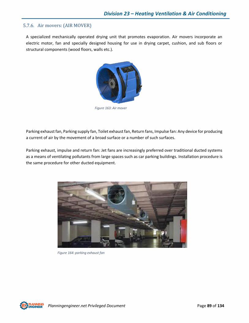
Planningengineer.net Privileged Document Page 89 of 134
Division 23 – Heating Ventilation & Air Conditioning
Air movers: (AIR MOVER)
A specialized mechanically operated drying unit that promotes evaporation. Air movers incorporate an
electric motor, fan and specially designed housing for use in drying carpet, cushion, and sub floors or
structural components (wood floors, walls etc.).
Parking exhaust fan, Parking supply fan, Toilet exhaust fan, Return fans, Impulse fan: Any device for producing
a current of air by the movement of a broad surface or a number of such surfaces.
Parking exhaust, impulse and return fan: Jet fans are increasingly preferred over traditional ducted systems
as a means of ventilating pollutants from large spaces such as car parking buildings. Installation procedure is
the same procedure for other ducted equipment.
Figure 163: Air mover
Figure 164: parking exhaust fan

Planningengineer.net Privileged Document Page 90 of 134
Division 23 – Heating Ventilation & Air Conditioning
Parking supply fan: Depending on the ventilation concept of the individual car park and the defined safety
standards, supply fans in addition to the exhaust fans may be installed. Installation procedure is the same
procedure for other ducted equipment.
Sound Attenuators: An assembly installed in a duct system to absorb sound. Attenuators are electronic
devices that decrease the amplitude or power of a signal without considerably distorting its waveform. They
are passive devices that are made from simple voltage divider networks. These equipment are duct inline
equipment that shall be bolted to dusts.
Figure 166: Sound Attenuator
Figure 165: parking supply fan
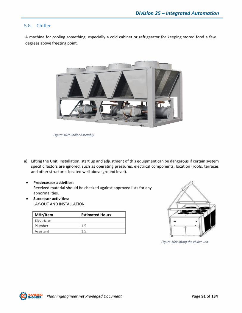
Planningengineer.net Privileged Document Page 91 of 134
Division 25 – Integrated Automation
5.8. Chiller
A machine for cooling something, especially a cold cabinet or refrigerator for keeping stored food a few
degrees above freezing point.
a) Lifting the Unit: Installation, start up and adjustment of this equipment can be dangerous if certain system specific factors are ignored, such as operating pressures, electrical components, location (roofs, terraces and other structures located well above ground level).
Predecessor activities: Received material should be checked against approved lists for any abnormalities.
Successor activities: LAY-OUT AND INSTALLATION
MHr/Item Estimated Hours
Electrician
Plumber 1.5
Assistant 1.5
Figure 167: Chiller Assembly
Figure 168: lifting the chiller unit
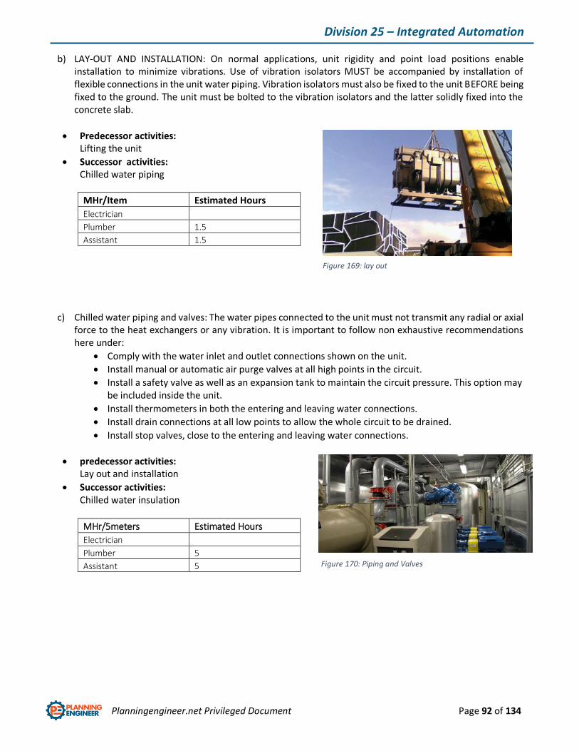
Planningengineer.net Privileged Document Page 92 of 134
Division 25 – Integrated Automation
b) LAY-OUT AND INSTALLATION: On normal applications, unit rigidity and point load positions enable installation to minimize vibrations. Use of vibration isolators MUST be accompanied by installation of flexible connections in the unit water piping. Vibration isolators must also be fixed to the unit BEFORE being fixed to the ground. The unit must be bolted to the vibration isolators and the latter solidly fixed into the concrete slab.
Predecessor activities: Lifting the unit
Successor activities: Chilled water piping
MHr/Item Estimated Hours
Electrician
Plumber 1.5
Assistant 1.5
c) Chilled water piping and valves: The water pipes connected to the unit must not transmit any radial or axial force to the heat exchangers or any vibration. It is important to follow non exhaustive recommendations here under:
Comply with the water inlet and outlet connections shown on the unit.
Install manual or automatic air purge valves at all high points in the circuit.
Install a safety valve as well as an expansion tank to maintain the circuit pressure. This option may be included inside the unit.
Install thermometers in both the entering and leaving water connections.
Install drain connections at all low points to allow the whole circuit to be drained.
Install stop valves, close to the entering and leaving water connections.
predecessor activities: Lay out and installation
Successor activities: Chilled water insulation
MHr/5meters Estimated Hours
Electrician
Plumber 5
Assistant 5
Figure 169: lay out
Figure 170: Piping and Valves

Planningengineer.net Privileged Document Page 93 of 134
Division 25 – Integrated Automation
d) Chilled water insulation: Insulate all pipe work, to reduce thermal leaks and to prevent condensation. If the external water pipes are in an area, where the ambient temperature is likely to fall below 0°C, insulate.
Predecessor activities: Chilled water piping and valves
Successor activities: ELECTRICAL CONNECTIONS
e) ELECTRICAL cabling and connection: First of all, make sure that power supplies from the building to the place where the unit is installed are properly established and that wire gauges are in keeping with the start up and running currents. Check tightness of all electrical connections.
Predecessor activities: Chilled water insulation
Successor activities: Pre commissioning
MHr/5meters Estimated Hours
Electrician
Plumber 4
Assistant 4
MHr/5meters Estimated Hour
Electrician 2
Plumber
Assistant 2
Figure 171: chilled water insulation
Figure 172: Electrical connection
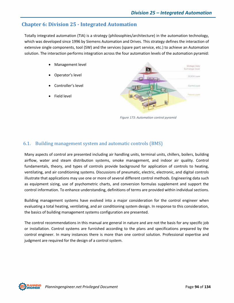
Planningengineer.net Privileged Document Page 94 of 134
Division 25 – Integrated Automation
Chapter 6: Division 25 - Integrated Automation
Totally integrated automation (TIA) is a strategy (philosophies/architecture) in the automation technology,
which was developed since 1996 by Siemens Automation and Drives. This strategy defines the interaction of
extensive single components, tool (SW) and the services (spare part service, etc.) to achieve an Automation
solution. The interaction performs integration across the four automation levels of the automation pyramid:
Management level
Operator’s level
Controller’s level
Field level
6.1. Building management system and automatic controls (BMS)
Many aspects of control are presented including air handling units, terminal units, chillers, boilers, building
airflow, water and steam distribution systems, smoke management, and indoor air quality. Control
fundamentals, theory, and types of controls provide background for application of controls to heating,
ventilating, and air conditioning systems. Discussions of pneumatic, electric, electronic, and digital controls
illustrate that applications may use one or more of several different control methods. Engineering data such
as equipment sizing, use of psychometric charts, and conversion formulas supplement and support the
control information. To enhance understanding, definitions of terms are provided within individual sections.
Building management systems have evolved into a major consideration for the control engineer when
evaluating a total heating, ventilating, and air conditioning system design. In response to this consideration,
the basics of building management systems configuration are presented.
The control recommendations in this manual are general in nature and are not the basis for any specific job
or installation. Control systems are furnished according to the plans and specifications prepared by the
control engineer. In many instances there is more than one control solution. Professional expertise and
judgment are required for the design of a control system.
Figure 173: Automation control pyramid
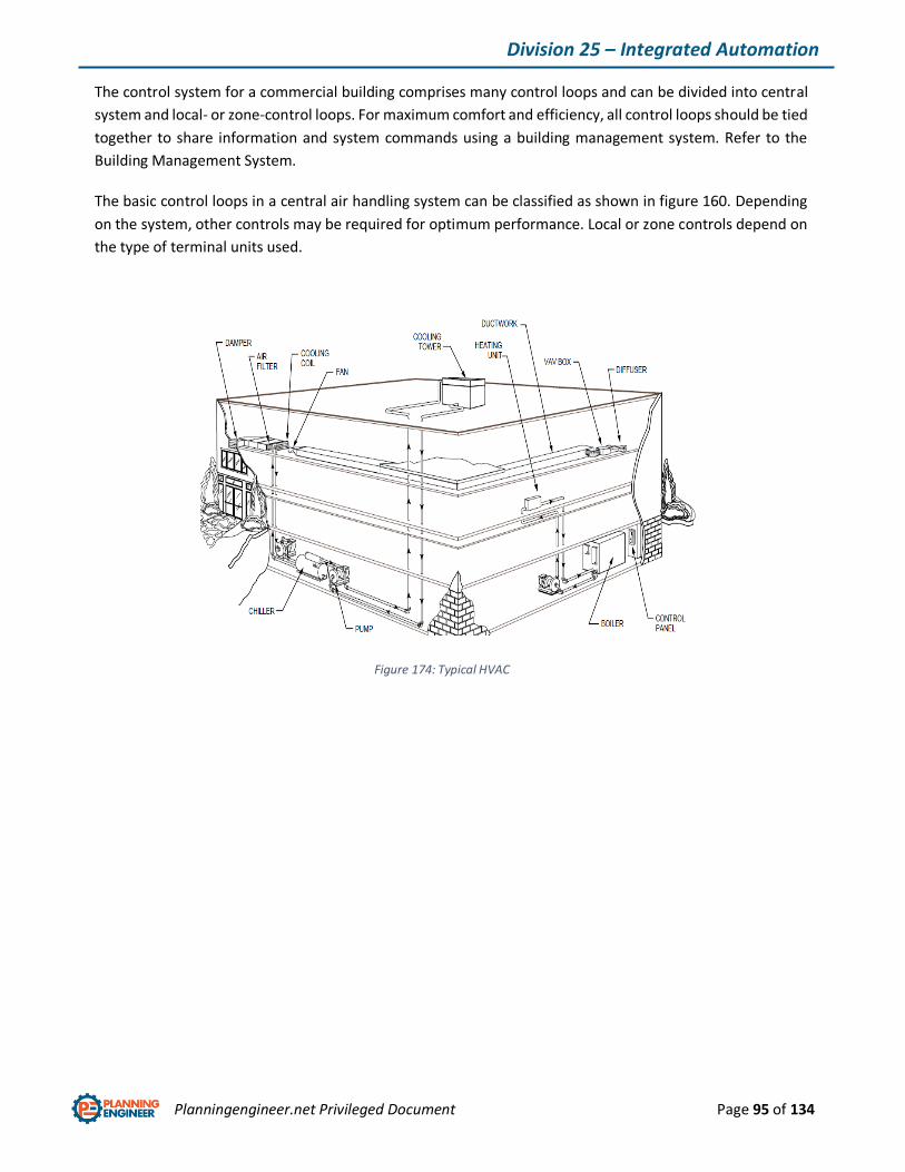
Planningengineer.net Privileged Document Page 95 of 134
Division 25 – Integrated Automation
The control system for a commercial building comprises many control loops and can be divided into central
system and local- or zone-control loops. For maximum comfort and efficiency, all control loops should be tied
together to share information and system commands using a building management system. Refer to the
Building Management System.
The basic control loops in a central air handling system can be classified as shown in figure 160. Depending
on the system, other controls may be required for optimum performance. Local or zone controls depend on
the type of terminal units used.
Figure 174: Typical HVAC control system
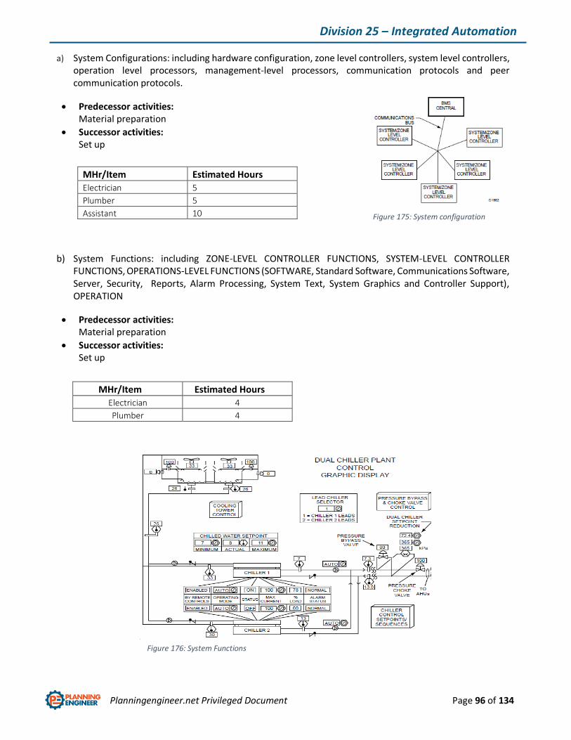
Planningengineer.net Privileged Document Page 96 of 134
Division 25 – Integrated Automation
a) System Configurations: including hardware configuration, zone level controllers, system level controllers, operation level processors, management-level processors, communication protocols and peer communication protocols.
Predecessor activities: Material preparation
Successor activities: Set up
b) System Functions: including ZONE-LEVEL CONTROLLER FUNCTIONS, SYSTEM-LEVEL CONTROLLER FUNCTIONS, OPERATIONS-LEVEL FUNCTIONS (SOFTWARE, Standard Software, Communications Software, Server, Security, Reports, Alarm Processing, System Text, System Graphics and Controller Support), OPERATION
Predecessor activities: Material preparation
Successor activities: Set up
MHr/Item Estimated Hours
Electrician 5
Plumber 5
Assistant 10
MHr/Item Estimated Hours
Electrician 4
Plumber 4
Figure 175: System configuration
Figure 176: System Functions
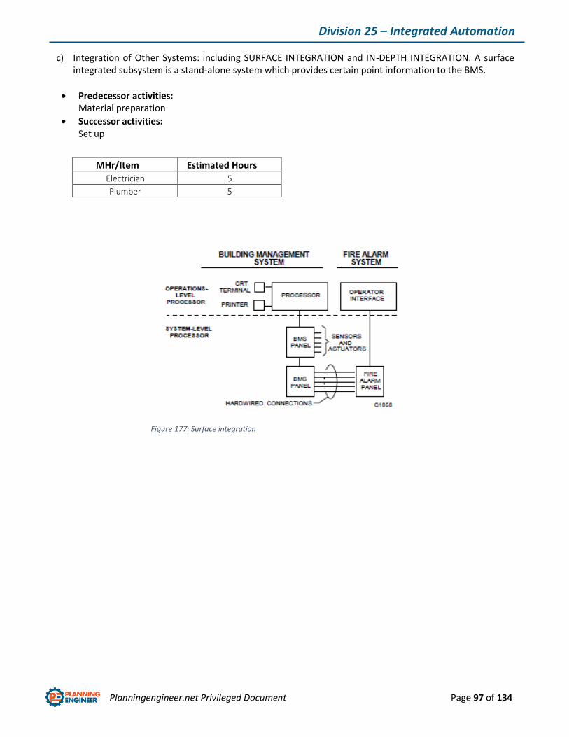
Planningengineer.net Privileged Document Page 97 of 134
Division 25 – Integrated Automation
c) Integration of Other Systems: including SURFACE INTEGRATION and IN-DEPTH INTEGRATION. A surface integrated subsystem is a stand-alone system which provides certain point information to the BMS.
Predecessor activities: Material preparation
Successor activities: Set up
MHr/Item Estimated Hours
Electrician 5
Plumber 5
Figure 177: Surface integration

Planningengineer.net Privileged Document Page 98 of 134
Division 26 – Electrical
Chapter 7: Division 26 - Electrical
6.2. LV and MV Electrical distribution
Electricity distribution is the final stage in the delivery of electricity to end users. A distribution system's
network carries electricity from the transmission system and delivers it to consumers. Typically, the network
would include medium-voltage (2kV to 34.5kV)[1] power lines, substations and pole-mounted transformers,
low-voltage (less than 1 kV) distribution wiring such as a Service Drop and sometimes meters.
General Activity: Liaise with electrical supply authority SEC and to co-ordinate supply and connection of the
main incomer.
The liaison between electrical supply authority and project manager shall be done according to state
electrical commission roles and project charter and scope statement.
MV, LV and HV Switchgear: In an electric power system, a switchgear is the combination of electrical
disconnect switches, fuses or circuit breakers used to control, protect and isolate electrical equipment.
Switchgears are used both to de-energize equipment to allow work to be done and to clear faults
downstream. This type of equipment is directly linked to the reliability of the electricity supply.
Figure 178: Electrical supply commission
Figure 179: switchgear layout
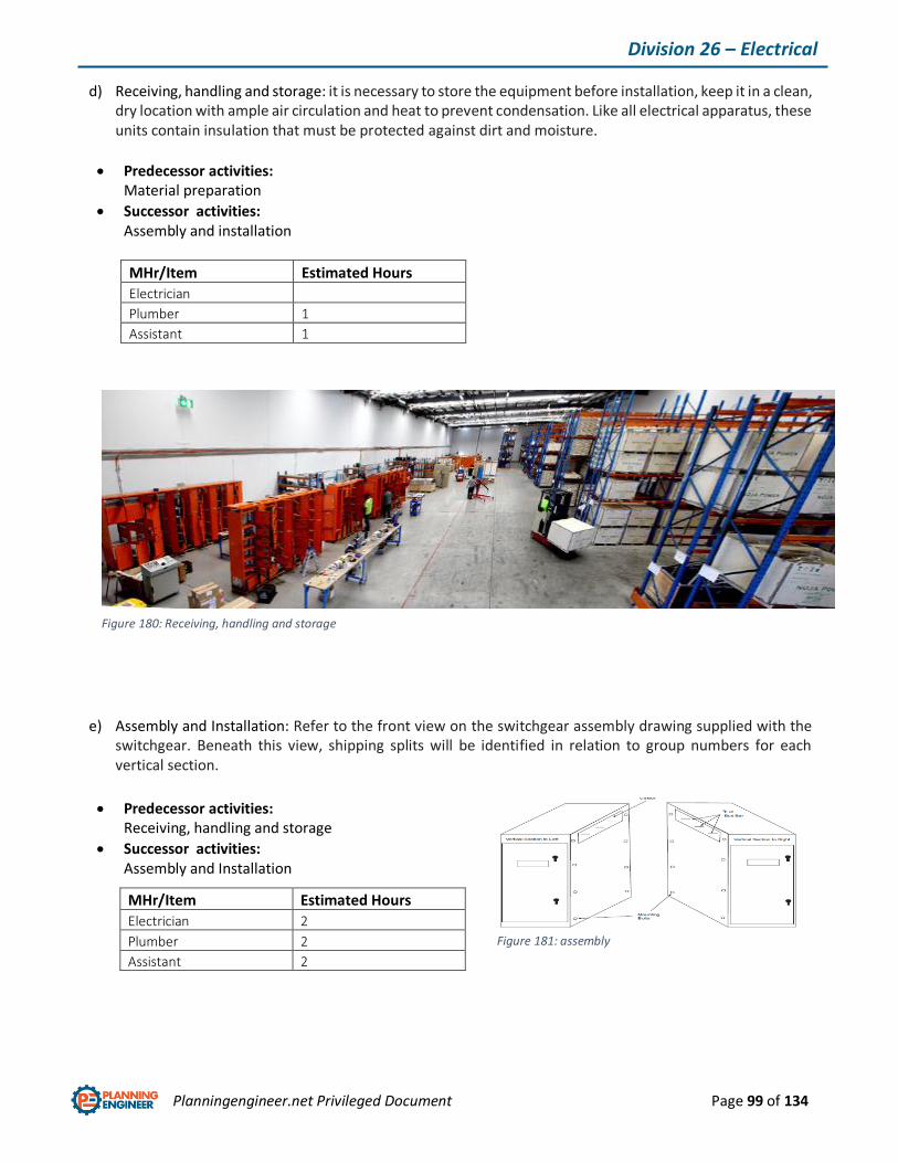
Planningengineer.net Privileged Document Page 99 of 134
Division 26 – Electrical
d) Receiving, handling and storage: it is necessary to store the equipment before installation, keep it in a clean, dry location with ample air circulation and heat to prevent condensation. Like all electrical apparatus, these units contain insulation that must be protected against dirt and moisture.
Predecessor activities: Material preparation
Successor activities: Assembly and installation
MHr/Item Estimated Hours
Electrician
Plumber 1
Assistant 1
e) Assembly and Installation: Refer to the front view on the switchgear assembly drawing supplied with the switchgear. Beneath this view, shipping splits will be identified in relation to group numbers for each vertical section.
Predecessor activities: Receiving, handling and storage
Successor activities: Assembly and Installation
MHr/Item Estimated Hours
Electrician 2
Plumber 2
Assistant 2
Figure 180: Receiving, handling and storage
Figure 181: assembly
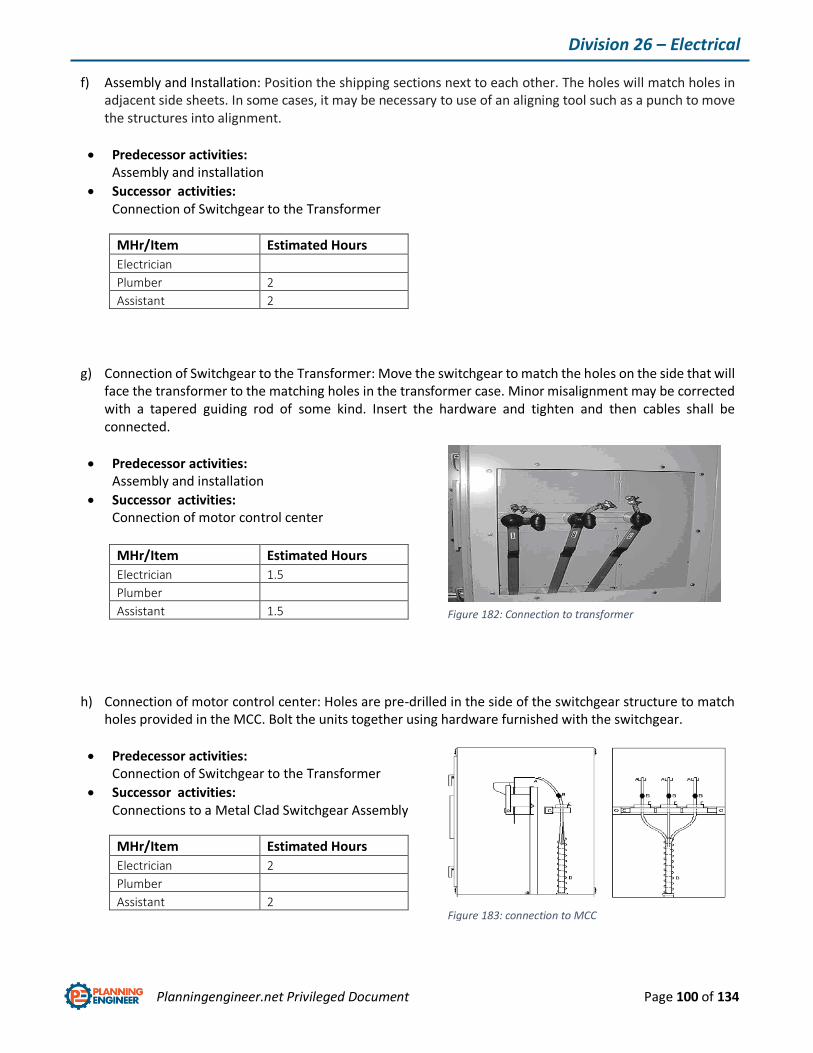
Planningengineer.net Privileged Document Page 100 of 134
Division 26 – Electrical
f) Assembly and Installation: Position the shipping sections next to each other. The holes will match holes in adjacent side sheets. In some cases, it may be necessary to use of an aligning tool such as a punch to move the structures into alignment.
Predecessor activities: Assembly and installation
Successor activities: Connection of Switchgear to the Transformer
MHr/Item Estimated Hours
Electrician
Plumber 2
Assistant 2
g) Connection of Switchgear to the Transformer: Move the switchgear to match the holes on the side that will face the transformer to the matching holes in the transformer case. Minor misalignment may be corrected with a tapered guiding rod of some kind. Insert the hardware and tighten and then cables shall be connected.
Predecessor activities: Assembly and installation
Successor activities: Connection of motor control center
MHr/Item Estimated Hours
Electrician 1.5
Plumber
Assistant 1.5
h) Connection of motor control center: Holes are pre-drilled in the side of the switchgear structure to match holes provided in the MCC. Bolt the units together using hardware furnished with the switchgear.
Predecessor activities: Connection of Switchgear to the Transformer
Successor activities: Connections to a Metal Clad Switchgear Assembly
MHr/Item Estimated Hours
Electrician 2
Plumber
Assistant 2
Figure 182: Connection to transformer
Figure 183: connection to MCC

Planningengineer.net Privileged Document Page 101 of 134
Division 26 – Electrical
i) Connections to a Metal Clad Switchgear Assembly: Position the units side by side. The holes in side sheet around bus cutout will match the holes in metal clad switchgear flange. Join the enclosures using the bolts supplied with switchgear. The opposite side of the metal clad switchgear flange has nuts welded in place for ease of connection.
Predecessor activities: Connection of motor control center
Successor activities: Connection of Customer Power Cables
MHr/Item Estimated Hours
Electrician 2
Plumber
Assistant 2
j) Connection of Customer Power Cables: For incoming power, the terminals are usually located at the top of the switch in a vertical section.
Predecessor activities: Connections to a Metal Clad Switchgear Assembly
Successor activities: Field Insulation
MHr/10meters Estimated Hours
Electrician 2
Plumber
Assistant 2

Planningengineer.net Privileged Document Page 102 of 134
Division 26 – Electrical
k) Field insulation methods: Clean the area of dirt and foreign matter. Use a clean, dry cloth or, if necessary, dampen slightly with distilled water. Do not use any abrasives or solvents. Place the boot over the joint so it fits in place. Fasten together with plastic wire ties. Cut off excess ends of plastic wire ties.
Predecessor activities: Connection of Customer Power Cables
Successor activities: Securing Switchgear Assemblies to Foundations
MHr/Item Estimated Hours
Electrician
Plumber 5
Assistant 5
l) Securing Switchgear Assemblies to Foundations: It shall be followed the instructions on the specific drawings provided for the switchgear assembly that address the anchoring details. Another drawing addresses the load bearing requirements. Indoor or outdoor vertical sections are secured using clips and foundation bolts. Anchors and lag screws may be used in place of J-bolts if desired.
Predecessor activities: Field insulation methods
Successor activities: Start-up
MHr/Item Estimated Hours
Electrician
Plumber 2
Assistant 2
Figure 184: Field insulation
Figure 185: Securing to foundation

Planningengineer.net Privileged Document Page 103 of 134
Division 26 – Electrical
6.3. Transformer
A transformer is an electrical device that transfers energy between two circuits through electromagnetic
induction. A transformer may be used as a safe and efficient voltage converter to change the AC voltage at
its input to a higher or lower voltage at its output without changing the frequency. Other uses include current
conversion, isolation with or without changing voltage and impedance conversion.
a) Storage: Liquid filled transformers can be stored for extended periods of time before being placed into service, if properly prepared. Liquid filled transformers may be stored outdoors. It is recommended that the transformer be completely assembled prior to storage. Storage instruction shall be carefully followed in accordance with manufacturer’s manual.
Predecessor activities: Material preparation
Successor activities: Installation location
MHr/Item Estimated Hours
Electrician
Plumber 2
Assistant 2
Figure 186: transformer installation

Planningengineer.net Privileged Document Page 104 of 134
Division 26 – Electrical
b) Installation location: The installation location of a transformer must be carefully considered. Transformers, as is the case with most electrical equipment, generate a substantial amount of heat during operation. This heat must be removed in order to allow the transformer to maintain its designed maximum temperature limits.
Predecessor activities: Storage
Successor activities: Assembly
MHr/Item Estimated Hours
Electrician
Plumber 3
Assistant 3
c) Assembly: These items should be reassembled in the following order: De-mounted Radiators, Bushings, Pressure Relief Device, Pressure Vacuum Gauge, Fans, Rapid Pressure Rise Relay and Lightning Arrestors.
Predecessor activities: Installation location
Successor activities: Cooling fans installation
MHr/Item Estimated Hours
Electrician
Plumber 6
Assistant 6
d) Cooling fans installation: Cooling fans serve to increase the transformer’s load capacity and to avoid overheating the windings. The fans are controlled by a “Manual” and “Auto” switch, and by contacts in either the winding or fluid temperature gauges.
Predecessor activities: Assembly
Successor activities: Installation of Conservator
MHr/Item Estimated Hours
Electrician
Plumber 1
Assistant 1
Figure 187: installation location
Figure 188: transformer site assembly
Figure 189: Cooling fans installation
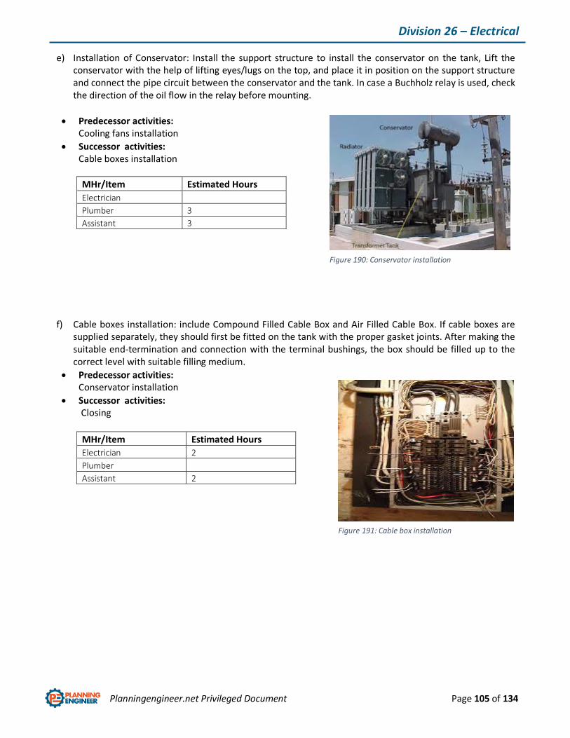
Planningengineer.net Privileged Document Page 105 of 134
Division 26 – Electrical
e) Installation of Conservator: Install the support structure to install the conservator on the tank, Lift the conservator with the help of lifting eyes/lugs on the top, and place it in position on the support structure and connect the pipe circuit between the conservator and the tank. In case a Buchholz relay is used, check the direction of the oil flow in the relay before mounting.
Predecessor activities: Cooling fans installation
Successor activities: Cable boxes installation
MHr/Item Estimated Hours
Electrician
Plumber 3
Assistant 3
f) Cable boxes installation: include Compound Filled Cable Box and Air Filled Cable Box. If cable boxes are supplied separately, they should first be fitted on the tank with the proper gasket joints. After making the suitable end-termination and connection with the terminal bushings, the box should be filled up to the correct level with suitable filling medium.
Predecessor activities: Conservator installation
Successor activities: Closing
MHr/Item Estimated Hours
Electrician 2
Plumber
Assistant 2
Figure 190: Conservator installation
Figure 191: Cable box installation
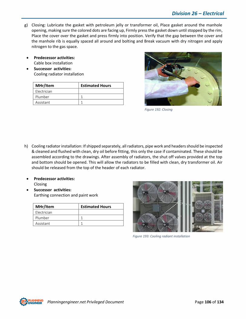
Planningengineer.net Privileged Document Page 106 of 134
Division 26 – Electrical
g) Closing: Lubricate the gasket with petroleum jelly or transformer oil, Place gasket around the manhole opening, making sure the colored dots are facing up, Firmly press the gasket down until stopped by the rim, Place the cover over the gasket and press firmly into position. Verify that the gap between the cover and the manhole rib is equally spaced all around and bolting and Break vacuum with dry nitrogen and apply nitrogen to the gas space.
Predecessor activities: Cable box installation
Successor activities: Cooling radiator installation
MHr/Item Estimated Hours
Electrician
Plumber 1
Assistant 1
h) Cooling radiator installation: If shipped separately, all radiators, pipe work and headers should be inspected & cleaned and flushed with clean, dry oil before fitting, this only the case if contaminated. These should be assembled according to the drawings. After assembly of radiators, the shut off valves provided at the top and bottom should be opened. This will allow the radiators to be filled with clean, dry transformer oil. Air should be released from the top of the header of each radiator.
Predecessor activities: Closing
Successor activities: Earthing connection and paint work
MHr/Item Estimated Hours
Electrician
Plumber 1
Assistant 1
Figure 192: Closing
Figure 193: Cooling radiant installation
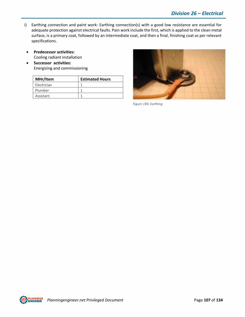
Planningengineer.net Privileged Document Page 107 of 134
Division 26 – Electrical
i) Earthing connection and paint work: Earthing connection(s) with a good low resistance are essential for adequate protection against electrical faults. Pain work include the first, which is applied to the clean metal surface, is a primary coat, followed by an intermediate coat, and then a final, finishing coat as per relevant specifications.
Predecessor activities: Cooling radiant installation
Successor activities: Energizing and commissioning
MHr/Item Estimated Hours
Electrician 1
Plumber 1
Assistant 1
Figure 194: Earthing

Planningengineer.net Privileged Document Page 108 of 134
Division 26 – Electrical
6.4. Cable distribution
Including splicing, connections and terminations, test and commissioning.
a) Cable splicing: A joint in electrical cable is called cable splicing. There are different ways to joint cables that shall be done according to project ITP and P&IDs.
Predecessor activities: Cable preparation
Successor activities: Connection and termination
MHr/3meter Estimated Hours
Electrician 2
Plumber
Assistant 2
b) Connection and termination: RF frequency signals travelling in coaxial cable will reflect off any impedance that does not match the 75-ohm impedance of the cable. This will cause serious signal distortion. For this reason, the ends of all the trunk and distribution cables are terminated with a 75-ohm load to ground.
Predecessor activities: Cable splicing
Successor activities: Commissioning
MHr/Item Estimated Hours
Electrician 2
Plumber
Assistant 2
Figure 195: Cable splicing
Figure 196: Termination

Planningengineer.net Privileged Document Page 109 of 134
Division 26 – Electrical
6.5. Pump Control panel
Electrical device consisting of a flat insulated surface that contains switches and dials and meters for
controlling other electrical devices. Normally, control panel is installed in pump frame and just need to
connect electric cables and termination.
6.6. Automatic transfer switch
A transfer switch is an electrical switch that switches a load between two sources. Some transfer switches
are manual, in that an operator effects the transfer by throwing a switch, while others are automatic and
switch when they sense one of the sources has lost or gained power. This equipment shall be simply bolted
to the wall or masonry farming. Electrical cables shall be connected and terminated.
Figure 197: control panel
Figure 198: transfer switch
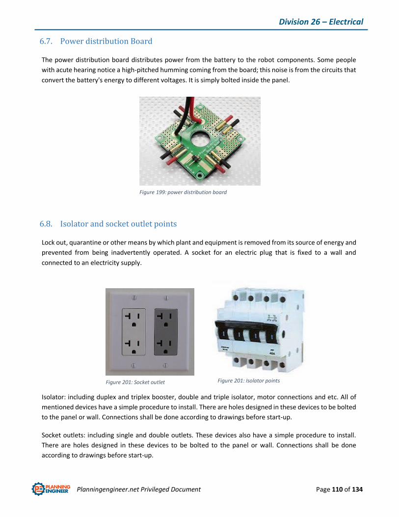
Planningengineer.net Privileged Document Page 110 of 134
Division 26 – Electrical
6.7. Power distribution Board
The power distribution board distributes power from the battery to the robot components. Some people
with acute hearing notice a high-pitched humming coming from the board; this noise is from the circuits that
convert the battery's energy to different voltages. It is simply bolted inside the panel.
6.8. Isolator and socket outlet points
Lock out, quarantine or other means by which plant and equipment is removed from its source of energy and
prevented from being inadvertently operated. A socket for an electric plug that is fixed to a wall and
connected to an electricity supply.
Isolator: including duplex and triplex booster, double and triple isolator, motor connections and etc. All of
mentioned devices have a simple procedure to install. There are holes designed in these devices to be bolted
to the panel or wall. Connections shall be done according to drawings before start-up.
Socket outlets: including single and double outlets. These devices also have a simple procedure to install.
There are holes designed in these devices to be bolted to the panel or wall. Connections shall be done
according to drawings before start-up.
Figure 199: power distribution board
Figure 201: Socket outlet Figure 201: Isolator points

Planningengineer.net Privileged Document Page 111 of 134
Division 26 – Electrical
6.9. Facility electrical power generation and storing equipment
Electricity generation is the process of generating electric power from other sources of primary energy.
Generator: an electric generator is a device that converts mechanical energy to electrical energy. A generator
forces electric current to flow through an external circuit. Installation procedure in here
Central battery system: A battery management system (BMS) is any electronic system that manages a
rechargeable battery (cell or battery pack), such as by protecting the battery from operating outside its Safe
Operating Area, monitoring its state, calculating secondary data, reporting that data, controlling its
environment, authenticating it and / or balancing it.
a) System installation: In the starting phase, the main switch must be in position 0 and the battery fuse must not be connected. The batteries are always placed in a separate battery container. The battery temperature sensor shall be placed between the batteries.
Predecessor activities: Material preparation
Successor activities: Connecting to main supply
MHr/Item Estimated Hours
Electrician .5
Plumber 2
Assistant 2
Figure 202: Central battery system
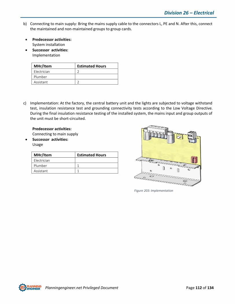
Planningengineer.net Privileged Document Page 112 of 134
Division 26 – Electrical
b) Connecting to main supply: Bring the mains supply cable to the connectors L, PE and N. After this, connect the maintained and non-maintained groups to group cards.
Predecessor activities: System installation
Successor activities: Implementation
MHr/Item Estimated Hours
Electrician 2
Plumber
Assistant 2
c) Implementation: At the factory, the central battery unit and the lights are subjected to voltage withstand test, insulation resistance test and grounding connectivity tests according to the Low Voltage Directive. During the final insulation resistance testing of the installed system, the mains input and group outputs of the unit must be short-circuited.
Predecessor activities: Connecting to main supply
Successor activities: Usage
MHr/Item Estimated Hours
Electrician
Plumber 1
Assistant 1
Figure 203: Implementation
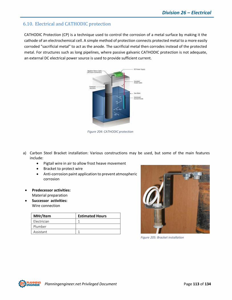
Planningengineer.net Privileged Document Page 113 of 134
Division 26 – Electrical
6.10. Electrical and CATHODIC protection
CATHODIC Protection (CP) is a technique used to control the corrosion of a metal surface by making it the
cathode of an electrochemical cell. A simple method of protection connects protected metal to a more easily
corroded "sacrificial metal" to act as the anode. The sacrificial metal then corrodes instead of the protected
metal. For structures such as long pipelines, where passive galvanic CATHODIC protection is not adequate,
an external DC electrical power source is used to provide sufficient current.
a) Carbon Steel Bracket installation: Various constructions may be used, but some of the main features include:
Pigtail wire in air to allow frost heave movement
Bracket to protect wire
Anti-corrosion paint application to prevent atmospheric corrosion
Predecessor activities: Material preparation
Successor activities: Wire connection
MHr/Item Estimated Hours
Electrician 1
Plumber
Assistant 1
Figure 204: CATHODIC protection
Figure 205: Bracket installation
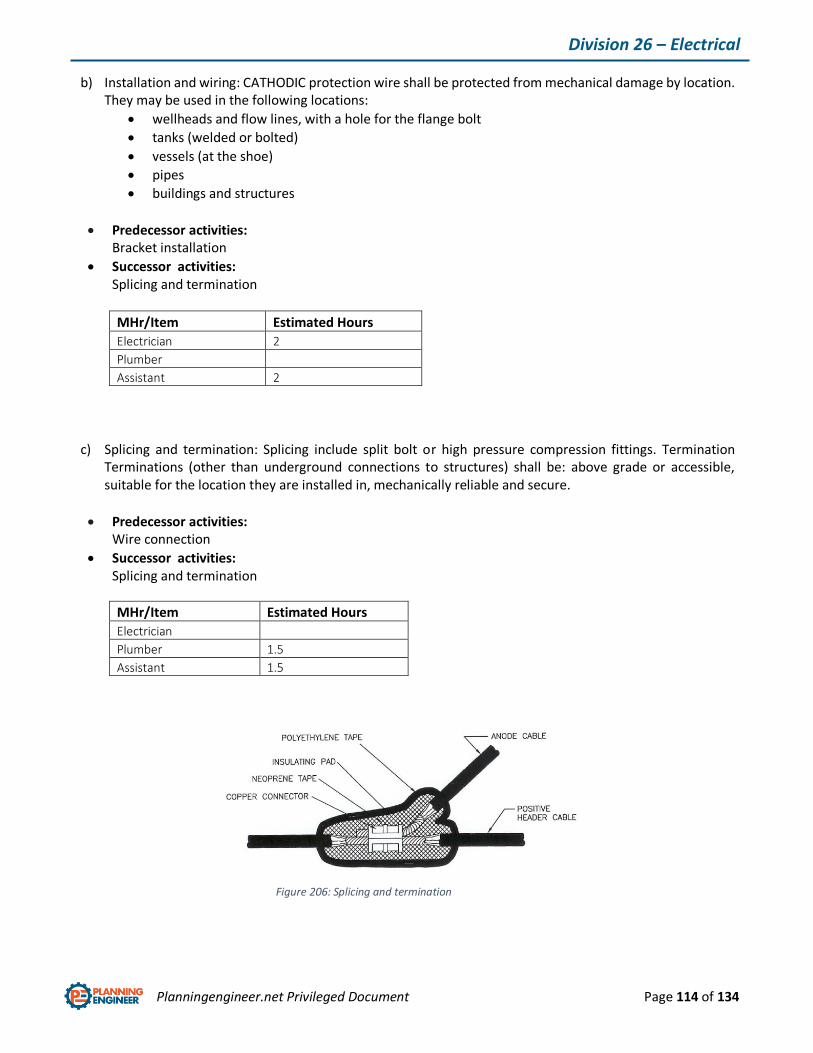
Planningengineer.net Privileged Document Page 114 of 134
Division 26 – Electrical
b) Installation and wiring: CATHODIC protection wire shall be protected from mechanical damage by location. They may be used in the following locations:
wellheads and flow lines, with a hole for the flange bolt
tanks (welded or bolted)
vessels (at the shoe)
pipes
buildings and structures
Predecessor activities: Bracket installation
Successor activities: Splicing and termination
MHr/Item Estimated Hours
Electrician 2
Plumber
Assistant 2
c) Splicing and termination: Splicing include split bolt or high pressure compression fittings. Termination Terminations (other than underground connections to structures) shall be: above grade or accessible, suitable for the location they are installed in, mechanically reliable and secure.
Predecessor activities: Wire connection
Successor activities: Splicing and termination
MHr/Item Estimated Hours
Electrician
Plumber 1.5
Assistant 1.5
Figure 206: Splicing and termination
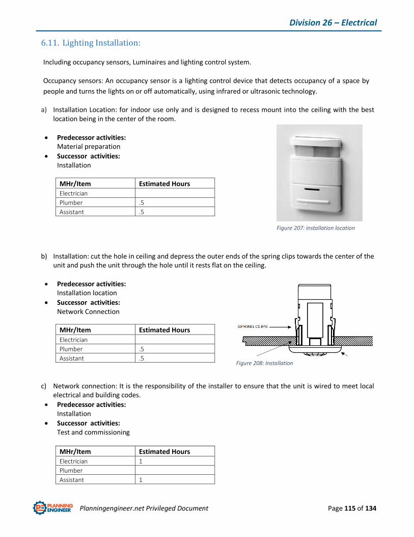
Planningengineer.net Privileged Document Page 115 of 134
Division 26 – Electrical
6.11. Lighting Installation:
Including occupancy sensors, Luminaires and lighting control system.
Occupancy sensors: An occupancy sensor is a lighting control device that detects occupancy of a space by
people and turns the lights on or off automatically, using infrared or ultrasonic technology.
a) Installation Location: for indoor use only and is designed to recess mount into the ceiling with the best location being in the center of the room.
Predecessor activities: Material preparation
Successor activities: Installation
MHr/Item Estimated Hours
Electrician
Plumber .5
Assistant .5
b) Installation: cut the hole in ceiling and depress the outer ends of the spring clips towards the center of the unit and push the unit through the hole until it rests flat on the ceiling.
Predecessor activities: Installation location
Successor activities: Network Connection
MHr/Item Estimated Hours
Electrician
Plumber .5
Assistant .5
c) Network connection: It is the responsibility of the installer to ensure that the unit is wired to meet local electrical and building codes.
Predecessor activities: Installation
Successor activities: Test and commissioning
MHr/Item Estimated Hours
Electrician 1
Plumber
Assistant 1
Figure 207: installation location
Figure 208: Installation
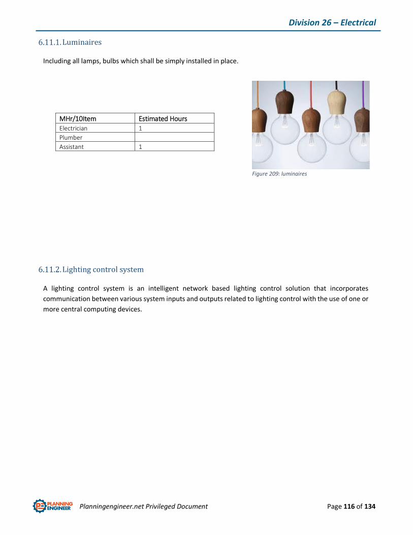
Planningengineer.net Privileged Document Page 116 of 134
Division 26 – Electrical
Luminaires
Including all lamps, bulbs which shall be simply installed in place.
MHr/10Item Estimated Hours
Electrician 1
Plumber
Assistant 1
Lighting control system
A lighting control system is an intelligent network based lighting control solution that incorporates
communication between various system inputs and outputs related to lighting control with the use of one or
more central computing devices.
Figure 209: luminaires
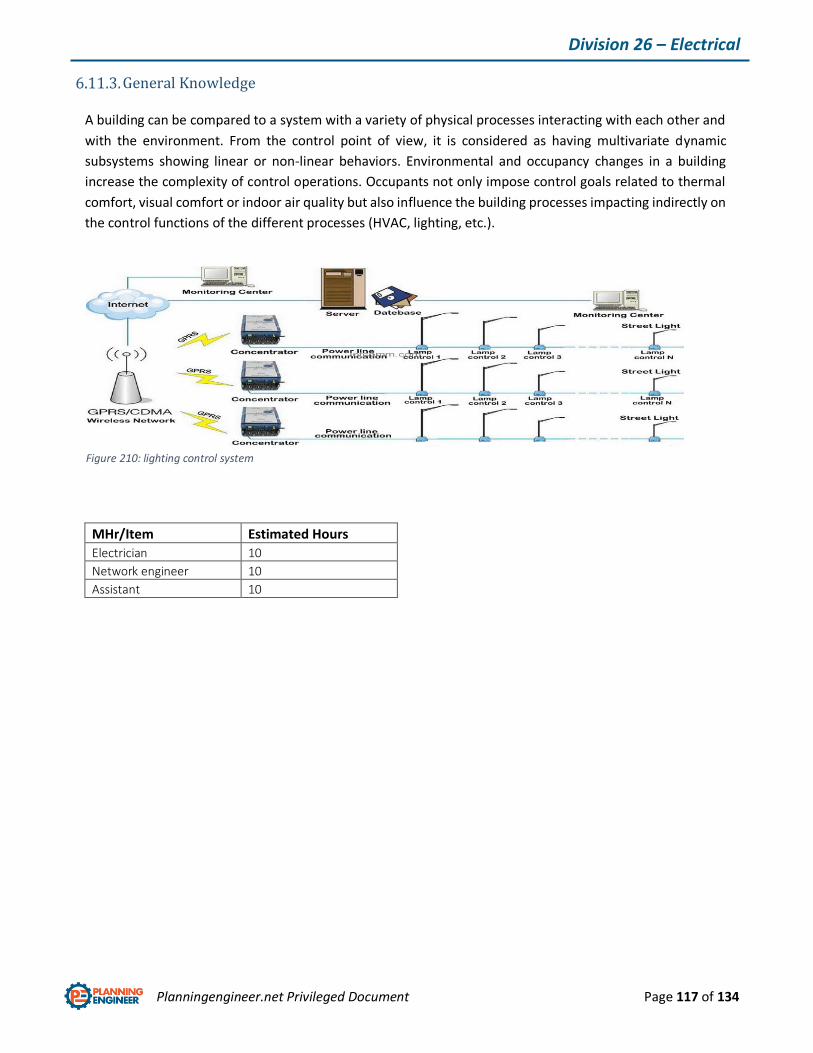
Planningengineer.net Privileged Document Page 117 of 134
Division 26 – Electrical
General Knowledge
A building can be compared to a system with a variety of physical processes interacting with each other and
with the environment. From the control point of view, it is considered as having multivariate dynamic
subsystems showing linear or non-linear behaviors. Environmental and occupancy changes in a building
increase the complexity of control operations. Occupants not only impose control goals related to thermal
comfort, visual comfort or indoor air quality but also influence the building processes impacting indirectly on
the control functions of the different processes (HVAC, lighting, etc.).
MHr/Item Estimated Hours
Electrician 10
Network engineer 10
Assistant 10
Figure 210: lighting control system
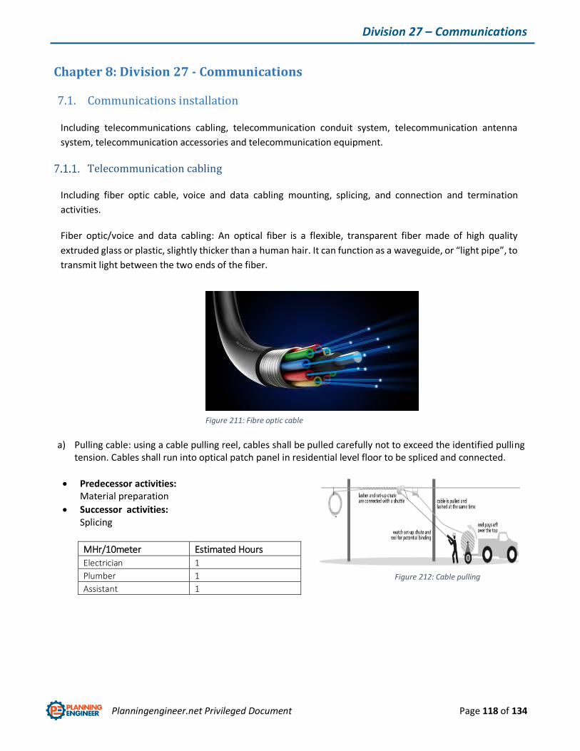
Planningengineer.net Privileged Document Page 118 of 134
Division 27 – Communications
Chapter 8: Division 27 - Communications
7.1. Communications installation
Including telecommunications cabling, telecommunication conduit system, telecommunication antenna
system, telecommunication accessories and telecommunication equipment.
Telecommunication cabling
Including fiber optic cable, voice and data cabling mounting, splicing, and connection and termination
activities.
Fiber optic/voice and data cabling: An optical fiber is a flexible, transparent fiber made of high quality
extruded glass or plastic, slightly thicker than a human hair. It can function as a waveguide, or “light pipe”, to
transmit light between the two ends of the fiber.
a) Pulling cable: using a cable pulling reel, cables shall be pulled carefully not to exceed the identified pulling tension. Cables shall run into optical patch panel in residential level floor to be spliced and connected.
Predecessor activities: Material preparation
Successor activities: Splicing
MHr/10meter Estimated Hours
Electrician 1
Plumber 1
Assistant 1
Figure 212: Cable pulling
Figure 211: Fibre optic cable
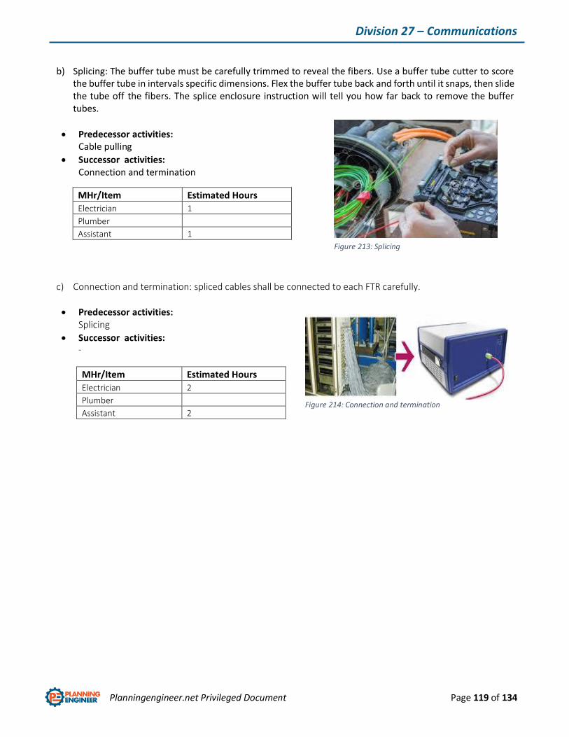
Planningengineer.net Privileged Document Page 119 of 134
Division 27 – Communications
b) Splicing: The buffer tube must be carefully trimmed to reveal the fibers. Use a buffer tube cutter to score the buffer tube in intervals specific dimensions. Flex the buffer tube back and forth until it snaps, then slide the tube off the fibers. The splice enclosure instruction will tell you how far back to remove the buffer tubes.
Predecessor activities: Cable pulling
Successor activities: Connection and termination
c) Connection and termination: spliced cables shall be connected to each FTR carefully.
Predecessor activities: Splicing
Successor activities: -
MHr/Item Estimated Hours
Electrician 2
Plumber
Assistant 2
MHr/Item Estimated Hours
Electrician 1
Plumber
Assistant 1
Figure 213: Splicing
Figure 214: Connection and termination
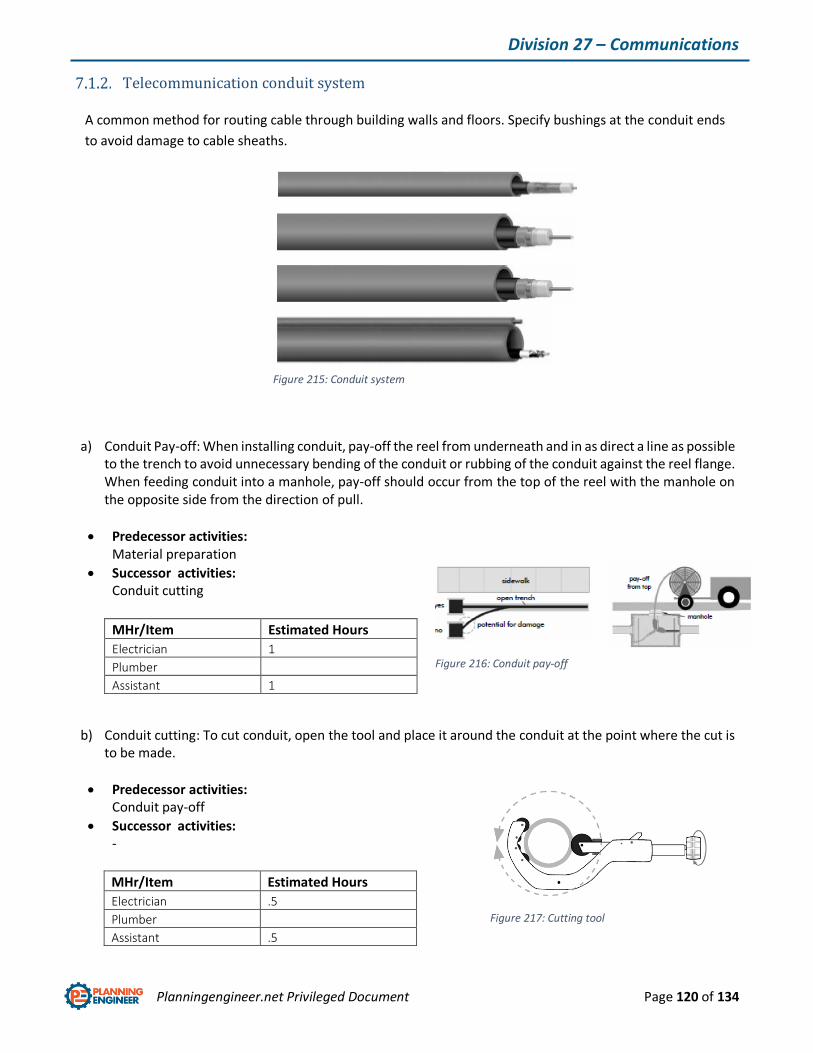
Planningengineer.net Privileged Document Page 120 of 134
Division 27 – Communications
Telecommunication conduit system
A common method for routing cable through building walls and floors. Specify bushings at the conduit ends
to avoid damage to cable sheaths.
a) Conduit Pay-off: When installing conduit, pay-off the reel from underneath and in as direct a line as possible to the trench to avoid unnecessary bending of the conduit or rubbing of the conduit against the reel flange. When feeding conduit into a manhole, pay-off should occur from the top of the reel with the manhole on the opposite side from the direction of pull.
Predecessor activities: Material preparation
Successor activities: Conduit cutting
b) Conduit cutting: To cut conduit, open the tool and place it around the conduit at the point where the cut is to be made.
Predecessor activities: Conduit pay-off
Successor activities: -
MHr/Item Estimated Hours
Electrician 1
Plumber
Assistant 1
MHr/Item Estimated Hours
Electrician .5
Plumber
Assistant .5
Figure 215: Conduit system
Figure 216: Conduit pay-off
Figure 217: Cutting tool
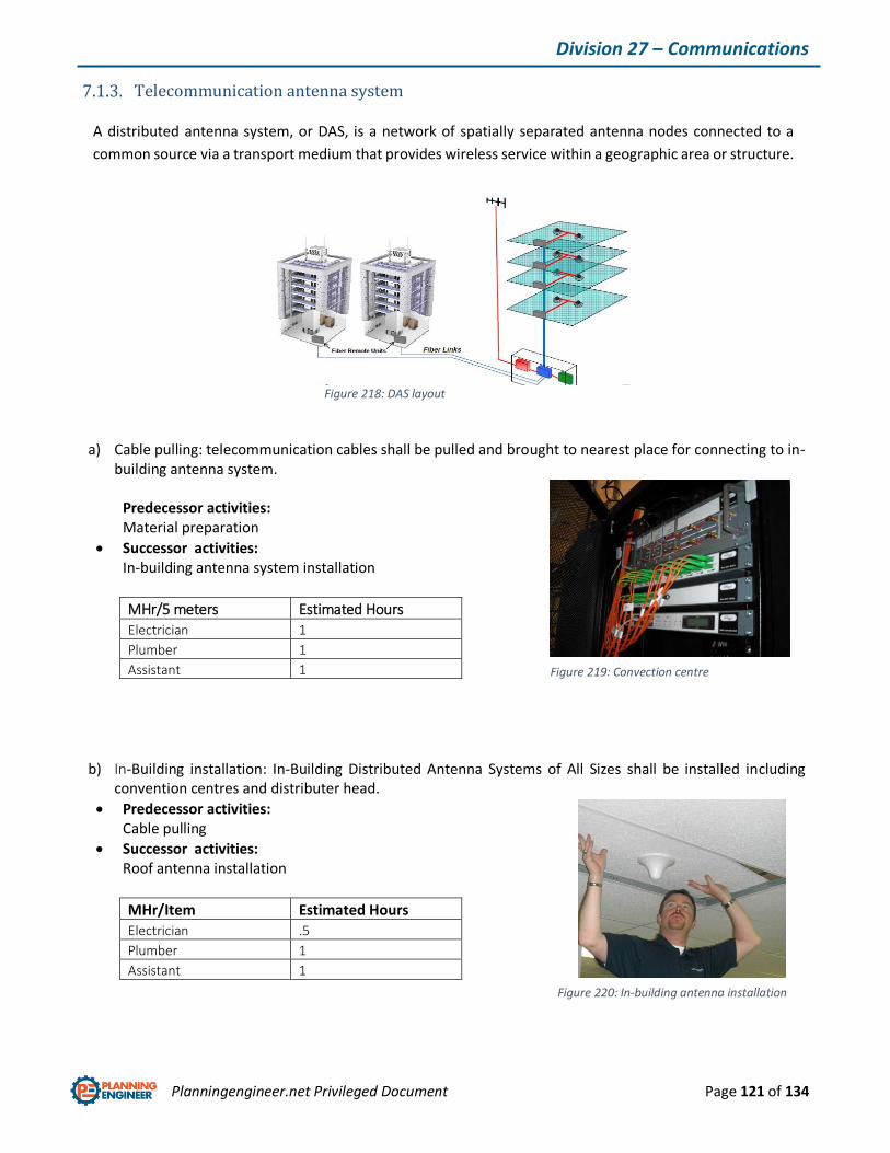
Planningengineer.net Privileged Document Page 121 of 134
Division 27 – Communications
Telecommunication antenna system
A distributed antenna system, or DAS, is a network of spatially separated antenna nodes connected to a
common source via a transport medium that provides wireless service within a geographic area or structure.
a) Cable pulling: telecommunication cables shall be pulled and brought to nearest place for connecting to in-building antenna system.
Predecessor activities: Material preparation
Successor activities: In-building antenna system installation
MHr/5 meters Estimated Hours
Electrician 1
Plumber 1
Assistant 1
b) In-Building installation: In-Building Distributed Antenna Systems of All Sizes shall be installed including convention centres and distributer head.
Predecessor activities: Cable pulling
Successor activities: Roof antenna installation
MHr/Item Estimated Hours
Electrician .5
Plumber 1
Assistant 1
Figure 218: DAS layout
Figure 220: In-building antenna installation
Figure 219: Convection centre

Planningengineer.net Privileged Document Page 122 of 134
Division 27 – Communications
c) Roof antenna installation and connection: floor antenna shall be installed in building floor and cables from convention centers shall be pulled through roof penetrations and connect to the roof antenna.
Predecessor activities: In-building installation
Successor activities: Commissioning
MHr/Item Estimated Hours
Electrician 1
Plumber 1
Assistant 1
d) Commissioning: cables shall be tested and all devices shall be commissioned separately.
Predecessor activities: In-building installation
Successor activities: -
MHr/Item Estimated Hours
Electrician 1.5
Plumber
Assistant 1.5
Figure 221: Roof antenna installation
Figure 222: Commissioning
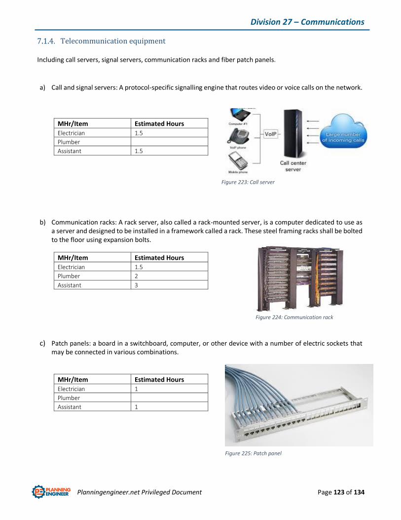
Planningengineer.net Privileged Document Page 123 of 134
Division 27 – Communications
Telecommunication equipment
Including call servers, signal servers, communication racks and fiber patch panels.
a) Call and signal servers: A protocol-specific signalling engine that routes video or voice calls on the network.
MHr/Item Estimated Hours
Electrician 1.5
Plumber
Assistant 1.5
b) Communication racks: A rack server, also called a rack-mounted server, is a computer dedicated to use as a server and designed to be installed in a framework called a rack. These steel framing racks shall be bolted to the floor using expansion bolts.
MHr/Item Estimated Hours
Electrician 1.5
Plumber 2
Assistant 3
c) Patch panels: a board in a switchboard, computer, or other device with a number of electric sockets that may be connected in various combinations.
MHr/Item Estimated Hours
Electrician 1
Plumber
Assistant 1
Figure 223: Call server
Figure 224: Communication rack
Figure 225: Patch panel

Planningengineer.net Privileged Document Page 124 of 134
Division 27 – Communications
7.2. Audio-Video Communications Installation
Audio-Video communication cabling: including HDMI, fiber optic cables and voice and data cabling.
Installation and operation of these cables match the communication cabling procedure.
Audio-Video communication accessories: including speakers (ceiling, floor and wall mounted), digital
projector, conference equipment (screen, video unit, media receiver and room controller, touch screen
panel, presenting mount), cinema equipment, skywalk projector, public address equipment (amplifier, disc
player).
a) Pulling cable: By using of conduits or sleeves which shall be drilled in wall, ceiling or floor, relevant cables shall be pulled through and brought into nearest place to connect to equipment. All above equipment shall be installed simply by positioning or bolting to ceiling, wall or floor.
Predecessor activities: Material preparation
Successor activities: Connecting to power supply
MHr/5 meters Estimated Hours
Electrician 2
Plumber 2
Assistant 2
Figure 226: Audio video cables
Figure 228: conference equipment Figure 228: Video projector

Planningengineer.net Privileged Document Page 125 of 134
Division 28 – Electronic Safety & Security
Chapter 9: Division 28 - Electronic Safety and Security
8.1. Electronic Access Control and Intrusion Detection
The Access Control and Intrusion Detection system is the Software House system which includes a
microprocessor based and managed access control system, with options for intrusion detection, and personal
protection (duress) security and specifies sensors, detection devices, signal equipment, system controls, and
displays.
Security and access control cabling: Security and access cabling follows the same instruction which has been
described for telecommunication cabling.
Security and access control accessories: including electric door strike, junction box, magnetic lock, panic bar,
passive in fared reader and proximity card reader.
Figure 229: Access Control and Intrusion Detection system
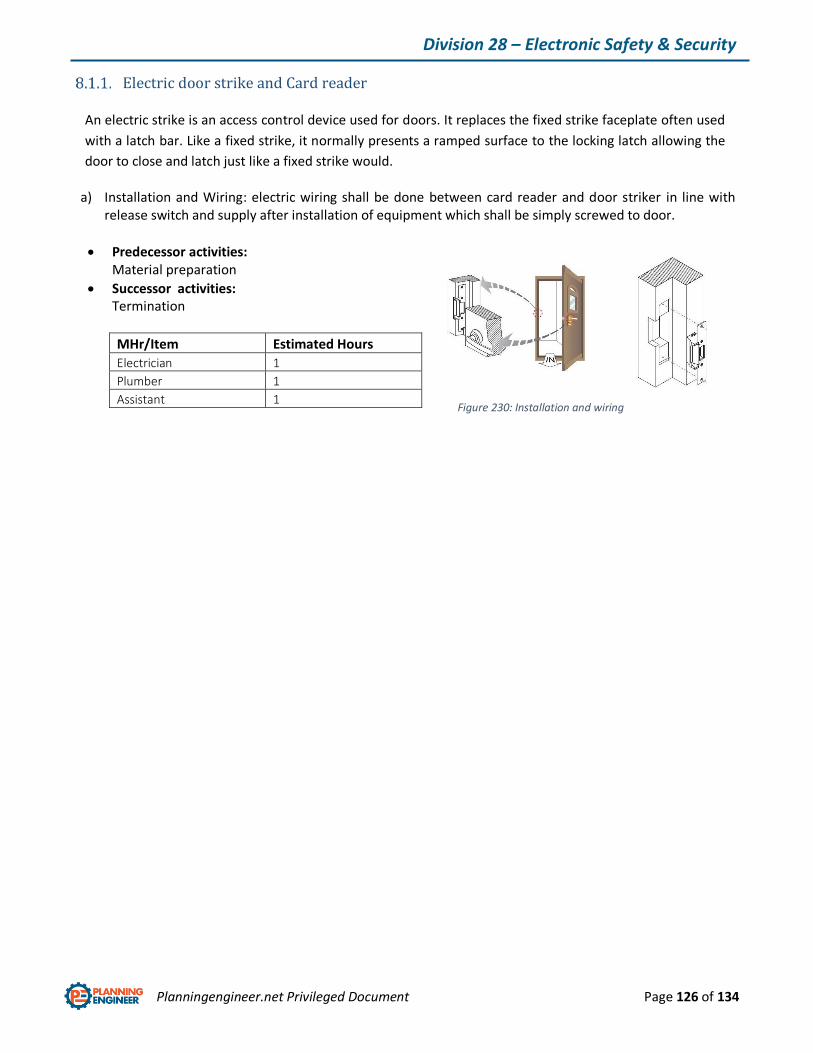
Planningengineer.net Privileged Document Page 126 of 134
Division 28 – Electronic Safety & Security
Electric door strike and Card reader
An electric strike is an access control device used for doors. It replaces the fixed strike faceplate often used
with a latch bar. Like a fixed strike, it normally presents a ramped surface to the locking latch allowing the
door to close and latch just like a fixed strike would.
a) Installation and Wiring: electric wiring shall be done between card reader and door striker in line with release switch and supply after installation of equipment which shall be simply screwed to door.
Predecessor activities: Material preparation
Successor activities: Termination
MHr/Item Estimated Hours
Electrician 1
Plumber 1
Assistant 1
Figure 230: Installation and wiring

Planningengineer.net Privileged Document Page 127 of 134
Division 28 – Electronic Safety & Security
Magnetic lock
An electromagnetic lock, magnetic lock, or mag-lock is a locking device that consists of an electromagnet and
an armature plate. There are two main types of electric locking devices. Locking devices can be either "fail
safe" or "fail secure".
a) Installation: magnetic lock frame shall be bolted top of the door in accordance with engineering drawings.
Predecessor activities: Material preparation
Successor activities: Wiring
MHr/Item Estimated Hours
Electrician
Plumber 2
Assistant 2
b) Wiring: electric wiring shall be done between equipment and supply system.
Predecessor activities: Installation
Successor activities: Termination
MHr/Item Estimated Hours
Electrician 2
Plumber
Assistant 2
Figure 231: Magnetic lock
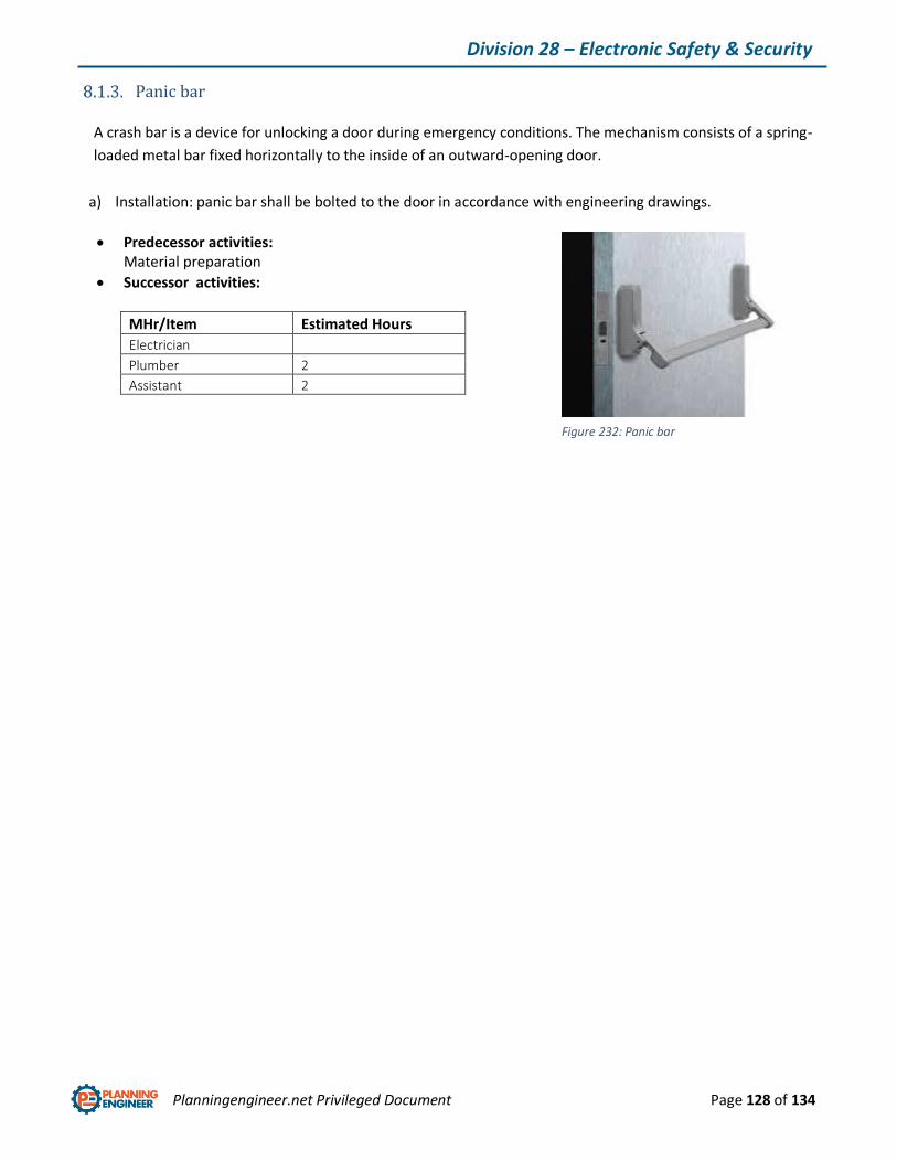
Planningengineer.net Privileged Document Page 128 of 134
Division 28 – Electronic Safety & Security
Panic bar
A crash bar is a device for unlocking a door during emergency conditions. The mechanism consists of a spring-
loaded metal bar fixed horizontally to the inside of an outward-opening door.
a) Installation: panic bar shall be bolted to the door in accordance with engineering drawings.
Predecessor activities: Material preparation
Successor activities:
MHr/Item Estimated Hours
Electrician
Plumber 2
Assistant 2
Figure 232: Panic bar
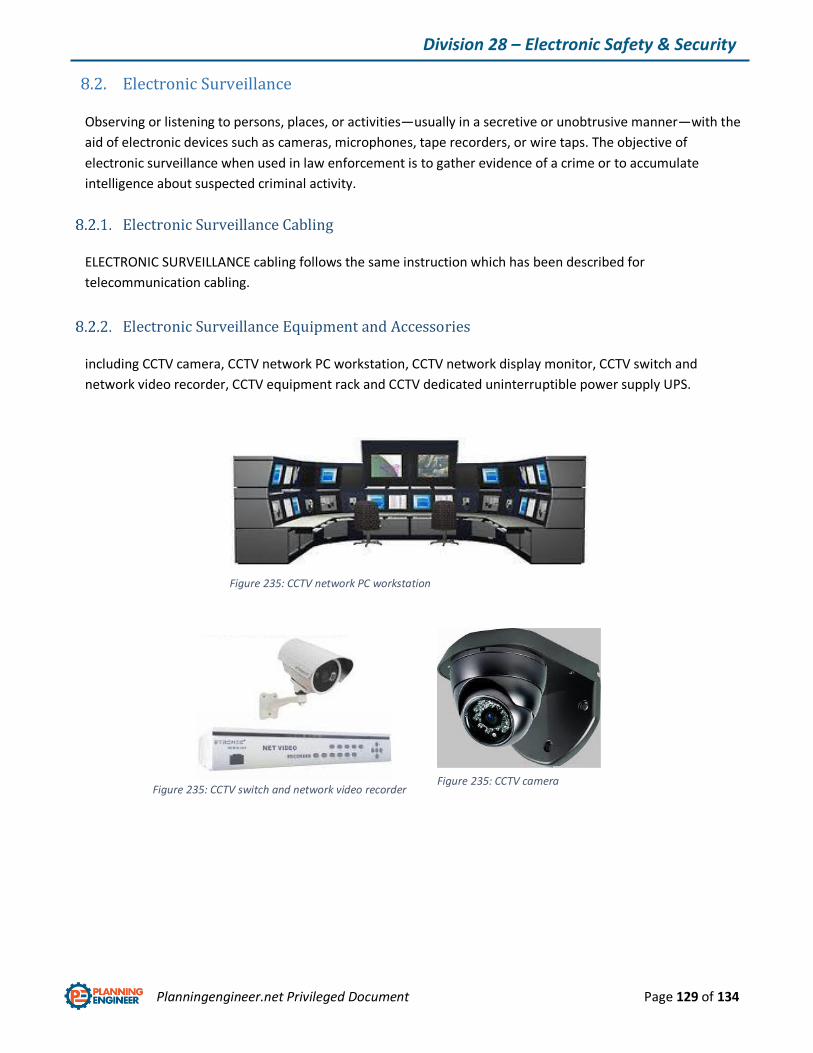
Planningengineer.net Privileged Document Page 129 of 134
Division 28 – Electronic Safety & Security
8.2. Electronic Surveillance
Observing or listening to persons, places, or activities—usually in a secretive or unobtrusive manner—with the
aid of electronic devices such as cameras, microphones, tape recorders, or wire taps. The objective of
electronic surveillance when used in law enforcement is to gather evidence of a crime or to accumulate
intelligence about suspected criminal activity.
Electronic Surveillance Cabling
ELECTRONIC SURVEILLANCE cabling follows the same instruction which has been described for
telecommunication cabling.
Electronic Surveillance Equipment and Accessories
including CCTV camera, CCTV network PC workstation, CCTV network display monitor, CCTV switch and
network video recorder, CCTV equipment rack and CCTV dedicated uninterruptible power supply UPS.
Figure 235: CCTV camera
Figure 235: CCTV network PC workstation
Figure 235: CCTV switch and network video recorder
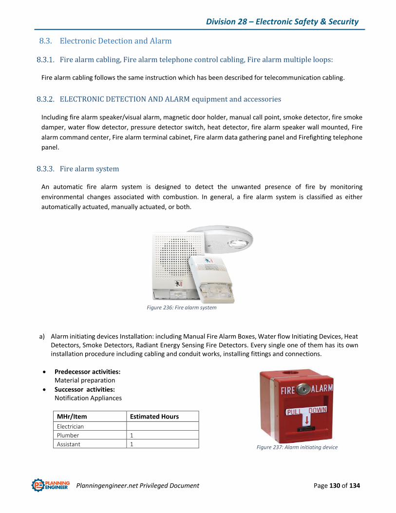
Planningengineer.net Privileged Document Page 130 of 134
Division 28 – Electronic Safety & Security
8.3. Electronic Detection and Alarm
Fire alarm cabling, Fire alarm telephone control cabling, Fire alarm multiple loops:
Fire alarm cabling follows the same instruction which has been described for telecommunication cabling.
ELECTRONIC DETECTION AND ALARM equipment and accessories
Including fire alarm speaker/visual alarm, magnetic door holder, manual call point, smoke detector, fire smoke
damper, water flow detector, pressure detector switch, heat detector, fire alarm speaker wall mounted, Fire
alarm command center, Fire alarm terminal cabinet, Fire alarm data gathering panel and Firefighting telephone
panel.
Fire alarm system
An automatic fire alarm system is designed to detect the unwanted presence of fire by monitoring
environmental changes associated with combustion. In general, a fire alarm system is classified as either
automatically actuated, manually actuated, or both.
a) Alarm initiating devices Installation: including Manual Fire Alarm Boxes, Water flow Initiating Devices, Heat Detectors, Smoke Detectors, Radiant Energy Sensing Fire Detectors. Every single one of them has its own installation procedure including cabling and conduit works, installing fittings and connections.
Predecessor activities: Material preparation
Successor activities: Notification Appliances
MHr/Item Estimated Hours
Electrician
Plumber 1
Assistant 1
Figure 236: Fire alarm system
Figure 237: Alarm initiating device
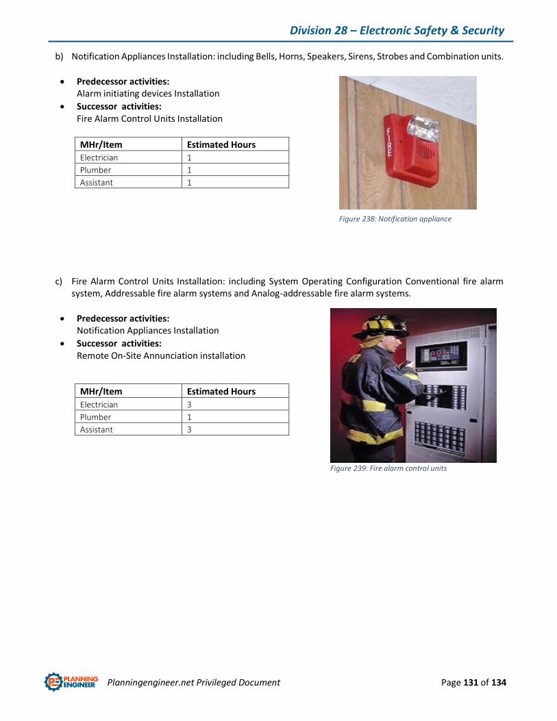
Planningengineer.net Privileged Document Page 131 of 134
Division 28 – Electronic Safety & Security
b) Notification Appliances Installation: including Bells, Horns, Speakers, Sirens, Strobes and Combination units.
Predecessor activities: Alarm initiating devices Installation
Successor activities: Fire Alarm Control Units Installation
MHr/Item Estimated Hours
Electrician 1
Plumber 1
Assistant 1
c) Fire Alarm Control Units Installation: including System Operating Configuration Conventional fire alarm system, Addressable fire alarm systems and Analog-addressable fire alarm systems.
Predecessor activities: Notification Appliances Installation
Successor activities: Remote On-Site Annunciation installation
MHr/Item Estimated Hours
Electrician 3
Plumber 1
Assistant 3
Figure 238: Notification appliance
Figure 239: Fire alarm control units

Planningengineer.net Privileged Document Page 132 of 134
Division 28 – Electronic Safety & Security
d) Remote On-Site Annunciation Installation: including Point Lighted Alphanumeric, Liquid Crystal Displays (LCD’s) and Graphic.
Predecessor activities: Fire Alarm Control Units Installation
Successor activities: Batteries installation
MHr/Item Estimated Hours
Electrician 2
Plumber 1
Assistant 3
e) Battery Installation: shall be installed for purpose of standby power.
Predecessor activities: Remote On-Site Annunciation Installation
Successor activities: Commissioning
MHr/Item Estimated Hours
Electrician 1
Plumber 1
Assistant 1
Figure 240: Remote on-site annunciation
Figure 241: fire alarm Battery

Planningengineer.net Privileged Document Page 133 of 134
Division 28 – Electronic Safety & Security
Magnetic door holder
A magnetic door holder is a hardware fixture which uses a magnet to hold a door open or closed.to install, simply
bolt the to both sides.
MHr/Item Estimated Hours
Electrician
Plumber .5
Assistant .5
Heat and smoke detector:
A heat detector is a fire alarm device designed to respond when the convicted thermal energy of a fire increases
the temperature of a heat sensitive element. The thermal mass and conductivity of the element regulate the
rate flow of heat into the element.
MHr/Item Estimated Hours
Electrician .5
Plumber .5
Assistant .5
Figure 242: Magnetic door holder
Figure 243: Heat/smoke detector

Planningengineer.net Privileged Document Page 134 of 134
We always have more!!
Follow our online store on our website “planningengineer.net”, you may be interested in
Primavera Online Course
Excel for Planners Online Course
Primavera top 50 tips and tricks
Various E-Books for your Planning Career
Preparing the Professional Planning Engineer Online Course
Or better then join our Premium Membership to get the full access for an open sky of E-Books, knowledge
and Online Courses.
For Any Inquiries or Information, Please contact us on [email protected]