contents - part a - instruction manual
TRANSCRIPT

Contents - part A - Instruction manual:
1. Proper use of the machine .................................................................................................................................................. 1
2. Description of the machine ................................................................................................................................................. 1
3. Machine sub-classes and sewing categories .................................................................................................................... 2
3.1 Sub-class .................................................................................................................................................................. 23.2 Sewing categories .................................................................................................................................................... 2
4. Survey of equipment ............................................................................................................................................................ 2
4.1 Equipment ................................................................................................................................................................. 24.1.1 Needles ........................................................................................................................................................... 24.1.2 Wheel feeders ................................................................................................................................................. 24.1.3 Top roller holders ........................................................................................................................................... 24.1.4 Top rollers ....................................................................................................................................................... 34.1.5 Throat plate .................................................................................................................................................... 34.1.6 Throat plate inserts ...................................................................................................... .................................. 34.1.7 Trimer knives .................................................................................................................................................. 34.1.8 Gauge for knife setting ................................................................................................... ................................ 34.1.9 Connecting cables of the head to the drive................................................................................ .................... 3
4.2 Optional eqiupment ................................................................................................................................................. 3
5. Technical data ..................................................................................................................................................................... 3
6. Operation of the machine .................................................................................................................................................... 5
6.1 Threading a thread ................................................................................................................................................... 56.2 Bobbin thread winding ............................................................................................................................................. 56.3 Inserting the bobbin and threading the lower thread ............................................................................................ 56.4 Regulating the thread tension ................................................................................................................................ 66.5 Needle replacement ................................................................................................................................................. 76.6 Regulation of pressing the top roller ...................................................................................................................... 76.7 Lifting the top roller up ............................................................................................................................................ 76.8 Reverse stitching ...................................................................................................................................................... 86.9 Stitch length adjustment .......................................................................................................................................... 86.10 Safety clutch ............................................................................................................................................................. 86.11 Starting of the material trimming operation .......................................................................................................... 86.12 Control of the material guide regardless the engaged trimming ......................................................................... 96.13 Control of the material guide with regard to the engaged trimming device ........................................................ 96.14 Setting of the material guide .................................................................................................................................. 96.15 Replacement of the trimming knife ........................................................................................................................ 106.16 Setting of the trimming device for trimming very small radii ............................................................................... 106.17 Setting of the trimming device for trimming thin, soft materials ......................................................................... 106.18 Change of the sewing category ............................................................................................................................... 106.19 Sharpening of the knives ......................................................................................................................................... 10
7. Electronic control of the machine ...................................................................................................................................... 11
7.1 Control of sewing by means of control elements ................................................................................................... 11
7.1.1 Via treadle ....................................................................................................................................................... 117.1.2 Via control pushbutton panel .............................................................................................. ........................... 117.1.3 Via control panel V810/V 820.............................................................................................. ........................... 11
7.2 Adjustment of automatic functions via control panel for stop motor ................................................................... 12
7.2.1 By using stop motor Efka with panel V 810 ................................................................................. .................. 127.2.1.1 Adjustment by means of buttons with fixed setting function ........................................................... 127.2.1.2 Setting by means of parameters ......................................................................................................... 13
7.2.2 By using stop motor Efka with panel V 820 ................................................................................................... 147.2.2.1 Adjustment by means of buttons with fixed setting function ........................................................... 157.2.2.2 Setting by means of parameters ......................................................................................................... 15
8. Maintenance ........................................................................................................................................................................ 16
Operating instructions for eventual trouble shooting ....................................................................................................... 17

Foreword
This instruction manual is intended to help the user to become familiar with the machine and take advantage of its applicationpossibilities in accordance with the recommendations.
The instruction manual contains important information on how to operate the machine securely, properly and economically.Observation of the instructions eliminates danger, reduces costs for repair and down-times, and increases the reliability and lifeof the machine.
The instruction manual is intended to complement existing national accident prevention and environment protection regulations.
The instruction manual must always be available at the machine/sewing unit.
The instruction manual must be read and applied by any person that is authorized to work on the machine/sewing unit. Thismeans:
- Operation, including equipping, troubleshooting during the work cycle, removing of fabric waste- Service (maintenance, inspection, repair and/or)- Transport.
The user also has to assure that only authorized personnel work on the machine.
The user is obliged to check the machine at least once per shift for apparent damages and to immediatly report any changes(including the performance in service), which impair the safety.
The user company must ensure that the machine is only operated in perfect working order.
Never remove or disable any safety devices.
If safety devices need to be removed for equipping, repairing or maintaining, the safety devices must be remounted directly aftercompletion of the maintenance and repair work.
Unauthorized modification of the machine rules out liability of the manufacturer for damage resulting from this.
Observe all safety and danger recommendations on the machine/unit! The yellow-and-black striped surfaces designate permanenddanger areas, eg danger of squashing, cutting, shearing or collision.
Besides the recommendations in this instruction manual also observe the general safety and accident prevention regulations!

General safety instructions
The non-observance of the following safety instructions can cause bodily injuries or damages to the machine.
1. The machine must only be commissioned of the instruction book and operated by persons with appropriate training.
2. Before putting into service also read the safety rules and instructions of the motor supplier.
3. The machine must be used only for the purpose intended. Use of the machine without the safety devices is not permitted. Observeall the relevant safety regulations.
4. When gauge parts are exchanged (e.g. needle, presser foot, needle plate, feed dog and bobbin) when tread-ing, when the workplaceis left, and during service work, the machine must be disconnected from the mains by switching off the master switch or disconnectingthe mains plug.
5. Daily servicing work must be carried out only by appropriately trained persons.
6. Repairs, conversion and special maintenance work must only be carried out by technicians or persons with appropriate training.
7. For service or repair work on pneumatic systems the machine must be disconnected from the compressed air supply system.Exceptions to this are only adjustments and functions checks made by appropriately trained technicians.
8. Work on the electrical equipment must be carried out only by electricians or appropriately trained persons.
9. Work on parts and systems under electric current is not permitted, except as specified in regulations DIN VDE 0105.
10. Conversion or changes to the machine must be authorized by us and made only in adherence to all safety regulations.
11. For repairs, only replacement parts approved by us must be used.
12. Commissioning of the sewing head is prohibited until such time as the entire sewing unit is found to comply with EC directives.
It is absolutely necessary to respect the safety instructions marked by these signs.Danger of bodily injuries !Please note also the general safety instructions.
IMPORTANT WARNING!
To the feeding network cord, it is necessary to connect the respective network plug which has been approved in the countryof utilizing the machine. This operation should be performed by a worker acquainted with the electric safety rules being inforce in the given country. The supplier is not responsible for any damages caused by defective plug or owing to incorrectassembly of the plug.
In spite of all safety measures made on the machines, inappropriate actions of the operator may lead to dangerous situations. Inindustrial sewing machines, attention should be paid to the following still remaining possible sources of injury:
1. Moving sewing needle- risk of injury when sewing with raised pressure foot or top roller, because the finger guard is then positioned too high.
2. Moving thread take-up lever- risk of injury when inadvertently or intentionally inserting the finger(s) between the thread take-up lever and its guard.
3. Moving pressure member- risk of injury when holding sewn work in immediate vicinity of the pressure member and beginning to insert under the pressure
member a considerably thicker sewn work portion,- risk of injury when sinking the pressure member.
4. When switched off, the clutch motor slows down by inertia but would be reactivated by an accidental tread-ing down of the motortreadle. To avoid such risk, it is advised to hold the handwheel by hand and slightly to depress the motor treadle.
5. Moving work cutter knife and work guide at the work cutter start- injury danger at incidental finger insertion under the cutter knife.
6. Moving connecting rod of the work cutter at the work cutter start- injury danger at incidental finger insertion between the connecting rod and the body of the work cutter.
7. Moving work cutter motor at the work cutter start- injury danger at incidental finger insertion between the motor and the work cutter guard.
1
Part A - Instruction manual1. Proper use of the machine
The machine is used in the shoemaking industry for sewing shoe uppers, for sewing on linings with simultaneous lining edgetrimming under the angle of 20° in the manufacture of shoe uppers. In addition to this, the machine serves for assemblingindividual shoe parts, as well as for decorative stitching without edge trimming. The machine is suitable for other similaroperations in the fancy goods industry. The machine is able to sewing upper leathers, natural or synthetic leather, eventually incombination with textile materials. Trimming is always to be done with a sharp knife. The knife is driven by a self-contained motorand its rear edge is situated 6 mm behind the needle axis. It ensures a good quality trimming of the lining material both in innerand outer curves. When trimming soft materials, the operator should maintain them, in pulling the trimmed lining behind theneedle, in a stretched condition to make the trimming operation easier.The machine sews using a double-thread lock stitch. A combined feeding ensures a uniform feeding of all layers to be sewntogether. The machine has got a standard outfit with the 134 KKL needles suitable for sewing leather. For sewing textile materials,the needle system 134 is being used. In general, only dry material may be sewn, which is not thicker than 6 mm after having beencompressed by the roller presser foot. The material should not contain any hard objects, for the machine is not provided with anyeye protector.For sewing, textile threads up to the dimension 500 dtex x 1 x 3 (label No 20) are to be used, namely synthetic, cotton or corespun threads. When needing other special threads, one must take into account the respective risks and proceed to the necessarysafety measures. When sewing very hard or consistent materials or when sewing with edge trimming, the sewing speed must beconsiderably reduced below the values given in the technical parameters of the machine.These special machines may be installed and operated only in dry rooms kept in orderly conditions. When operating them inrooms which do not meet such conditions, there must be done some additional measures according to the EN 60204-31standard. In our position of the manufacturers of industrial sewing machines, we start from the assumption that our products areoperated by an at least initiated operator, so that all usual operating activities and their eventual riks can be supposed to beknown.
Machine noisinessMachine noisiness has been measured in accordance with the standards ISO 3746, ISO 11204 at maximum speed.Laeq = equivalent machine noise of the self-standing machine on the working place, converted to % machine employment (dB)- stated in the table
2. Description of the machine
This is a one-needle post-bed sewing machine with a standard vertical hook situated to the right from the needle. The feeding isof a two-step type with a driven top roller presser foot and with a circular bottom feed combined with a needle feed during the firststep of the workpiece feeding. The main mechanisms are mounted on antifriction bearings, swing shafts and pins are slidinglymounted. Feeding is derived from the mechanism of changing stitch length through a friction clutch on the bottom feeding shaft.From here the circular feeder is driven by means of a roller chain. The drive of the roller presser foot is derived from the bottomfeeding shaft through an indented belt on the top feeding shaft through abevel gearing on an articulated vertical shaft. Theneedle feeding is derived from the same mechanism as the circular feeding. The stitch length is set using a knob on the web ofthe machine arm.The machine is provided with a thread trimming device, with an electromagnetic roller presser foot lifting, with an electromagneticbackward stitching. This backward stitching is controlled by a hand lever or by a microswitch in the event of having provided themachine with an electromagnetic backward stitching. The machine has got a sewing set mounted with changeable needle plateinserts according to the needle number and according to the distance of trimming from the needle. It i possible to choose theroller presser foot of 25, 35 or 45 mm. The standard vertical hook has got its own forced bobbin case opening. The hook isprotected by a protective coupling against overload with an adjustable switch-off moment. There is a central pressureless wicklubricating system. The hook is excluded from this system, it is lubricated separately with its own lubricating regulation. Eachmachine has got a built-in hook thread friction winder mounted. The machine can be provided with a halogen lamp lighting,eventually with further possible outfit. When the machine has no electromagnetic roller presser foot lifting, this lifting is controlledby the knee lever or, in case of deliveries for the Czech Republic, by the left pedal.The frame is fitted with a wedge. In accordance with the roller presser foot lifting outfit, the frame is fitted with one or two pedals.For the edge trimming operation, the machine is provided with an oblique top trimming device. The knife is driven by a leveragefrom a separate motor, which is situated on the machine arm. The knife is started by a lever and is automatically shifted into itsworking position. With machines provided with the EFKA stop motor, the motor of the trimming device is being switched on onlyat the beginning of the sewing operation and it is switched off with an adjustable delay after having ended the sewing operation.By returning the lever back, the lever movement is stopped and the knife moves upwards, outside from the sewn workpiece.Together with the machine there is supplied a tiltable material guide. Putting this guide in its working position is mechanicallyselectable either separately from the trimming operation or together with the trimming.
Type of the Noisiness % machinemachine dB employment
4182i-XXX-100 82 20
4182i-XXX-200 79 20
4182i-XXX-300 73 20
2
3. Machine sub-classes and sewing categories
3.1 Sub-class
Table 1
*for only Czech republic
3.2 Sewing categoriesThis code indication includes the equipment assembled on the machine head, both necessary equipment and optional equip-ment. The standard configuration of the equipment has been preset, according to the under mentioned table, in the factory whichincludes only necessary equipment. If the buyer demands a different configuration then the factory allocates a new codeindication.
Table 2Standard configuration - the numbers in brackets stand for ordering Nos. when ordering separately the Equipment in question
Type Needle size Top roller Wheel feeder Throat plate Throat plateinsert
Class-sub-class Diameter Pitch of teeth Width of hole -sewing category 0.01mm mm mm mm -
4180i-1XX-10080 35 0.4 1.2
(S548 134013) (M 173) (M 060) (M 191)
4180i-1XX-200100 35 0.4 1.5 (M 091)
(S548 134001) (M 173) (M 060) (M 192)
4180i-1XX-300 130 35 0.6 2.0(S548 000311) (M 173) (M 059) (M 193)
4. Survey of equipmentThis survey does not include the equipment assembled on the stand.
4.1 Equipment (at least one of each from the following group of equipment is assembled)
4.1.1 NeedlesM 020 - needle 134 LR size 80M 023 - needle 134 LR size 100M 021 - needle 134 LR size 130
4.1.2 Wheel feedersM 060 - wheel feeder with pitch of teeth 0.4 mmM 059 - wheel feeder with pitch of teeth 0.6 mmM 058 - wheel feeder with pitch of teeth 1.2 mm
4.1.3 Top roller holdersM 156 - holder for the top roller ø 25 mmM 157 - holder for the top roller ø 35 mmM 295 - holder for the top roller ø 45 mm
••
••
••
••
••
Type of Top roller lift Reverse stitching Threadthe machine trimmer
Class-subclass Via knee Treadle Via electro- Via electro- Via hand Via electro--sewing lever mag. + mag. + lever mag. +category knee lever treadle hand lever
4182i-111-XXX4182i-121-XXX*4182i-147-XXX4182i-157-XXX*
.
3
4.1.4 Top rollersM 172 - top roller ø 25 mmM 173 - top roller ø 35 mmM 174 - rubberized top roller ø 25 mmM 175 - rubberized top roller ø 35 mmM 310 - smooth top roller ø 25 mmM 311 - smooth top roller ø 35 mmM 296 - top roller ø 45 mm - width 2.0 mmM 297 - top roller ø 45 mm - width 3.8 mm
4.1.5 Sewing setM 143 - sewing set
4.1.6 Throat plate insertsM 191 - insert for throat plate (for needle 60-80; trimmed edge 0.8 mm)M 192 - insert for throat plate (for needle 80-110; trimmed edge 1.2 mm)M 193 - insert for throat plate (for needle 110-140; trimmed edge 1.5 mm)M 320 - insert for throat plate (for needle 110-140; trimmed edge 2.4 mm)M 321 - insert for throat plate (for needle 110-140; trimmed edge 3.0 mm)M 323 - insert for throat plate (for needle 110-140; trimmed edge 2.0 mm)
4.1.7 Trimmer knivesS425 870237 - trimmer knife �A� (hard metal)S080 870235 - trimmer knife �A� (steel)S080 870238 - trimmer knife �B� (steel)S080 870239 - trimmer knife �C� (steel)
4.1.8 Gauge for knife settingM 268 - gauge
4.1.9 Connecting cables of the head to the driveM 318 - connecting cable to the drive EFKA DC 1600/DA82GA; EFKA VD 552/6F82FA and EFKA VD 554/6F82FAM 055 - connecting cable without any specified drive (with free cable end)
Note: For the machine provided with a minimotor, the cable is component part of the drive thereof.
4.2 Optional equipmentM 010 - built-in lighting (including transformer 230/12V)M 269 - jig for knife sharpeningM 242 - setting gauge4182 111001V - high mortality spare parts kit in plastic box for sub-class without thread trimmer4182 147001V - high mortality spare parts kit in plastic box for sub-class with thread trimmerS794 222012 - halogen lighting (12 V, 20 W - contains transformer)
5. Technical dataTable 3a
Sewing Distance Stitch Labelled Number Sewing speed Hook Throat Thickness Play be-category between the length number of of needle (without trimming) plate of the top tween the
needle axis polyester thread insert material guide andand the work the knifetrimmer line
mm mm - - 0,01mm 0,01mm SPM SPM - - mm mm
- 1000,8 3 70 80-60 80 60-80 2500 3500 R 816 M191 0,8-1,2 0,2
- light
-2001,2 5 40 50-30 100 80-110 2500 3000 R 816 M192 1,2-1,6 0,3
- medium
- 3001,5 5 20 30-20 130 110-140 1600 2000 R 816 M193 1,6-2,4 0,4
- medium-heavy
Stan
dard
Max
imum
Stan
dard
Rang
e
Stan
dard
Rang
e
Stan
dard
Max
imum
Rang
e
Reco
mm
ende
d

4
Table 3b
Recommended speed at simultaneous work trimming
To observe: To obtain uniform stitch length, the sewing speed must be reduced. The recommended values apply to current leathersused in the shoe industry. For extremely soft or extremely hard leathers, tests should be carried out and the sewing speed shouldbe adjusted accordingly.
The recommended speed has been chosen so as to correspond to the assortment of the available pulleys.
Stitch type Double thread lock-stitch 301Hook R 816 - standard, verticalNeedle System 134; 134LR; 134 KKLRThreads max. 500 dtex x 1 x 3Stitch length max. 5 mm ± 10%Sewing speed max. 3500 SPM (the maximum sewing speed with the
simultaneous trimming is limited by the stitch lengthand by the hardness of the material being trimmed)
Top roller stroke 5,5 ± 0,5 mm - via hand lever12.5 ± 1 mm via electromagnet
Length of trimmed thread ends 8....11 mmHeight of post bed 173 mmOpening space of machine head 270 x 298 mmWeight of the head max. 55 kg (61 kg head with minimotor)Weitght of the stand max. 60 kg (38 kg for head with minimotor)Driving unit Clutch motor (min. 0.35 kW)
Stopmotor (min. 0.4 kW)Dimension of bed plate 178 x 518 mmInput machine max. 600 WTrimmed material max. thickness - 2,5 mmDistance between the needle axis and the work trimmer line 0,8 - 1,5 mm (according to sewing category)Power output of the work trimmer motor 25 WStroke frequency of the work trimmer knife 3500 strokes/min (constant)Stroke range of the work trimmer knife adjustable to 2,4 mmLayout dimensions of the machine (including the stand) 1060 x 550 mmHeight of the machine (including the stand) 1680 mm
Stitch length Sewing speed
mm SPM
1,5 2500
2,5 2000
4 1200
5 800
S080 870235 S425 870237 S080 870238 S080 870239
Thickness ofthe material trimmed
1 - 4 1,5 - 4 1 - 2 0,2 - 0,8
Minimum radius for thematerial being trimmed
~6 ~6 ~4 ~6
Knife stroke
2,4 2,4 1,2 2,4
stee
l
hard
mea
l
stee
l
stee
l
5
6. Operation of the machine
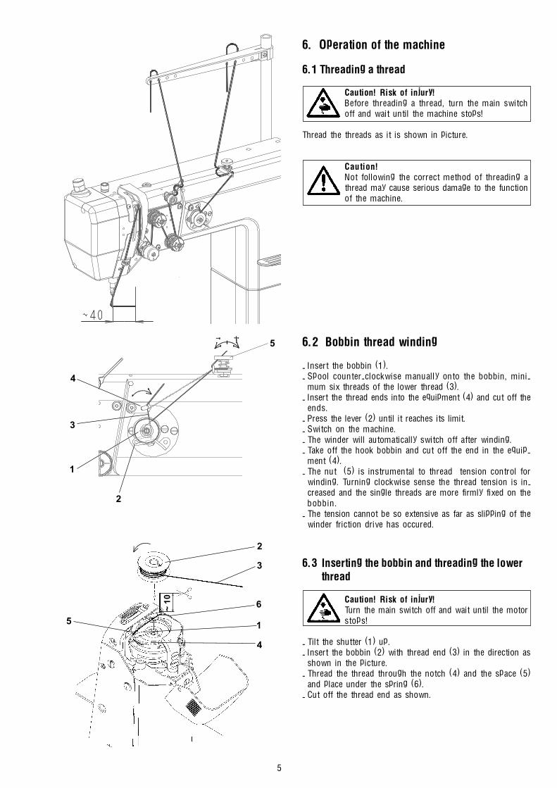
6.1 Threading a thread
Caution! Risk of injury!Before threading a thread, turn the main switchoff and wait until the machine stops!
Thread the threads as it is shown in picture.
Caution!Not following the correct method of threading athread may cause serious damage to the functionof the machine.
6.2 Bobbin thread winding
- Insert the bobbin (1).- Spool counter-clockwise manually onto the bobbin, mini-
mum six threads of the lower thread (3).- Insert the thread ends into the equipment (4) and cut off the
ends.- Press the lever (2) until it reaches its limit.- Switch on the machine.- The winder will automatically switch off after winding.- Take off the hook bobbin and cut off the end in the equip-
ment (4).- The nut (5) is instrumental to thread tension control for
winding. Turning clockwise sense the thread tension is in-creased and the single threads are more firmly fixed on thebobbin.
- The tension cannot be so extensive as far as slipping of thewinder friction drive has occured.
6.3 Inserting the bobbin and threading the lower thread
Caution! Risk of injury!Turn the main switch off and wait until the motorstops!
- Tilt the shutter (1) up.- Insert the bobbin (2) with thread end (3) in the direction as
shown in the picture.- Thread the thread through the notch (4) and the space (5)
and place under the spring (6).- Cut off the thread end as shown.
1
2
4
3
5
3
2
6~ 10
5
4
1
6
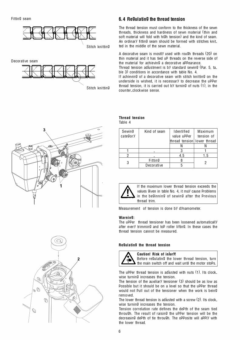
6.4 Regulating the thread tension
The thread tension must conform to the thickness of the sewnthreads, thickness and hardness of sewn material (thin andsoft material will fold with high tension) and the kind of seam.An ordinary fitting seam should be formed with stitches knit-ted in the middle of the sewn material.
A decorative seam is mostly used with rough threads (20) onthin material and it has tied up threads on the reverse side ofthe material for achieving a decorative appearance.Thread tension adjustment is by standard sewing (par. 5, ta-ble 3) conditions in accordance with table No. 4.If achieving of a decorative seam with stitch knitting on theunderside is wished, it is necessary to decrease the upperthread tension, it is carried out by turning of nuts (1), in thecounter-clockwise sense.
Thread tensionTable 4
Sewing Kind of seam Identified Maximumcategory value upper tension of
thread tension lower threadN N
1 - 3 12 - 4.5 1.5
3Fitting 8
2Decorative 5
If the maximum lower thread tension exceeds thevalues given in table No. 4, it may cause problemsin the beginning of sewing after the previousthread trim.
Measurement of tension is done by dynamometer.
Warning:The upper thread tensioner has been loosened automaticallyafter every trimming and top roller lifting. In these cases thethread tension cannot be measured.
Regulating the thread tension
Caution! Risk of injury!Before regulating the lower thread tension, turnthe main switch off and wait until the motor stops.
The upper thread tension is adjusted with nuts (1). Its clock-wise turning increases the tension.The tension of the auxiliary tensioner (3) should be as low aspossible but it should be on a level so that the upper threadwould not pull out of the tensioner when the work is beingremoved.The lower thread tension is adjusted with a screw (2). Its clock-wise turning increases the tension.Tension correlation rate defines the depth of the seam tiedthrough. The result of raising the upper tension will be thedecreasing depth of tie through. The opposite will apply withthe lower thread.
1
3
2
Fitting seam
Decorative seam
Stitch knitting
Stitch knitting

7
6.5 Needle replacement
Caution! Risk of injury!Before remowing and inserting the needle turnthe main switch off and wait until the motorstops!
- Turn with the hand wheel as far as the top needle (1) positionhas been reached.
- Loosen the screw (2) and take the needle out.- When inserting a new needle, care is to be taken that groove
(3) above the needle�s eye was in the same direction as thehook.
- Tighten the screw (2).
The inserted needle must respond to the sewingcategory according to paragraph No. 5, table 3.Otherwise it will cause damage to sewing, or even-tually the machine could be broken.
6.6 Regulation of pressing the top roller
The pressing of the top roller should be as low as possible buton a level so that the top roller would not fly over when needlecomes off the material and that the feeding power got overthe thread pull by stitch tightening.By turning of the screw (1) clockwise pressing of the top rollerhas been increased, by counter-clockwise turning pressing ofthe top roller has been decreased.
6.7 Lifting the top roller up
Mechanical lifting of the top roller is enabled by means of thehand lever (1), which contemporarily, after it has been lifted inthe arrow direction, is locking the top roller in its top positionand turning (adjustment) of the machine is possible. The toproller can be lifted via knee lever or left treadle - depending onthe machine sub-class. Automatical lifting by means of elec-tromagnet is described in the paragraph No. 7.
When lifting top roller via knee lever or the treadleor electromagnet, the needle must be in the upperposition and the machine has to come to a fullstop.
1
3
2
1
1

8
6.8 Reverse stitching
The change of direction of sewn work can be mechanicallycontrolled via a reverse stitching lever (1) by its depression inthe arrow direction (down). The sub-class defines whetherthe machine has electromagnetic reverse stitching � see para-graph No. 7.
6.9 Stitch length adjustment
Stitch length adjustment is by dial (2) by its turning. Turningclockwise stitch length is decreased, turning counter-clock-wise stitch is length increased.
6.10 Safety clutch
The machine is provided with a safety clutch which disen-gages the driving unit, when the hook is blocked. Reconnec-tion must be done in the following way:
Caution! Risk of injury!Before assembly turn the main switch off and waituntil the motor stops!
- Turn the manually operated wheel as far as you can reach thesuitable point for inserting a screwdriver into the space(1).
- Continue turning the manually operated wheel in directionof the arrow located on it, until you feel the drop in of thesafety clutch.
6.11 Starting of the material trimming operation
The trimming operation can be started at the beginning of theseam, but also at any moment during the sewing operation.In such case, the knife pierces the trimmed material and,starting from this spot, the trimming operation starts running.
- Put the material to be sewn under the presser foot.- Engage the trimming device in depressing the engaging
lever (1) downwards. The trimming knife (2) will movedownwards into its working position.
Caution! Risk of injury!When starting the trimming operation, do not putyour fingers under the trimming knife.
- Sew a seam.- Disengage the trimming device in pulling the engaging lever
(1) upwards.
Especially when starting the trimming operationin the middle of the trimmed material, do not exceed its maximum permissible thickness = 2.5 mm.This may break the trimming knife. When apply
ing the maximum sewing speed together with the maximumstitch length, a smooth trimming cut cannot be ensured. It isnecessary to reduce one or the other in proceeding to a teston the material to be trimmed.
1
2
1
1
2

9
6.12 Control of the material guide regardless theengaged trimming device
- Pull the sphere (1) in the direction of the arrow (A), until itspin disengages from the engagement with the lever (2).
- In depressing the handrail (3) downwards, lower the guide(4) into its working position. Using the inverse procedure,lift the guide upwards.
6.13 Control of the material guide with regard tothe engaged trimming device
- Disengage the trimming device by means of the lever (5) andlift the guide (4) in its top position
- Depress the sphere (1) in the direction of the arrow (B), untilits pin fits into the recess in the lever (2).
- Engage the trimming device using the lever (5). The guideshifts in its working position. When disengaging thetrimming device, the guide lifts too.
6.14 Setting of the material guide
Caution! Risk of injury!Proceed to the guide setting only with the ma-chine switched off!
- Switch off the machine with the main switch.- Engage the trimming device (lower the knife in its working
position).- Loosen the screw (1)- Loosen the screw (2) until the guide (3)bears against the
insert.- Using a screw driver, turn the shaft (5) in such a way, so that
the trimming knife is in its lowest position.- Push the guide in the direction of the arrow (B), until it bears
against the trimming knife, and tighten the screw (1).- In tightening the screw (2), set the guide (3) in such a way,
so that there is a space between the guide and the throatplate corresponding to the thickness of the material to betrimmed.
- Loosen the screw (6) inside the screw (7). Turn the screw(7) in the suitable direction, until the clearance �C� = 0.2 -0.4 mm between the guide and the trimming knife is set - seetable 3a, par. 5.
With an insufficient clerarance �C�, the knifestrikes against the guide and will be soon de-stroyed. With an excessive clearance �C�, the nee-dle strikes against the guide.
- Tighten the screw ( 6). In this way, the screw (7) will beblocked.
- The guide (3) may be set in height by means of the screw (2)even with the main switch switched on.
1
5
3
4
2
AB
76
2
1
3
5
B
C

10
2
1
5
3
4
6
6.15 Replacement of the trimming knife
Caution! Risk of injury!Replace the trimming knife only with the machineswitched off!
- Switch off the main switch of the machine.- Put the knife in its top position, loosen the screws (1) and
shift the knife (2) downwards.- Shift in the new knife, tighten only very slightly the screws
to have the knife in its holder (3) still slidable.- Place the gauge (4) on the throat plate in such a way, so that
the recess number corresponds with the number on the knife.- With a slow movement of the lever (5), lower the knife
downwards.- Using a screw driver, turn the shaft (6) in such a way, so that
the trimming knife is in its lowest position.- Push the free end of the trimming knife with a screwdriver,
until it bears into the recess in the gauge (4) and tightenthoroughly the screws (1)
- Lift the trimming knife, remove the gauge, lower the trimmingknife and check the movement of the trimming knife in turningthe shaft (6).
The trimming knife must not strike in its bottomdead centre against the throat plate insert. In thetop dead centre, the trimming knife must not leavethe cutting edge on the throat plate insert.
6.16 Setting of the trimming device for trimmingvery small radii
For trimming very small radii, the trimming knife �B� is to beused, it can be additionally purchased. In such case, thesetting inside the trimming mechanism must be changed. Thissetting change is described in the service book.
6.17 Setting of the trimming device for trimmingthin, soft materials
For this type of trimming, the trimming knife �C� is to be used,it can be additionally purchased. In such case the settinginside the trimming mechanism must be changed. This settingchange is described in the service book.
6.18 Change of the sewing category
When proceeding to this change, it is necessary to replace thethroat plate insert (it can be additionally purchased). Togetherwith the insert replacement, the width of the trimmed edge ischanged - the side setting of the knife must be changed. It isdescribed in the service book.
6.19 Sharpening of the knives
The knives of sintered carbide are to be sharpened using dia-mond abrasive material. A sharpening jig serving as a knifefastener for machine sharpening or directly for hand sharpe-ning on a whetstone (only steel knives) can be additionallypurchased. The sharpening procedure is described in the ser-vice book.
11
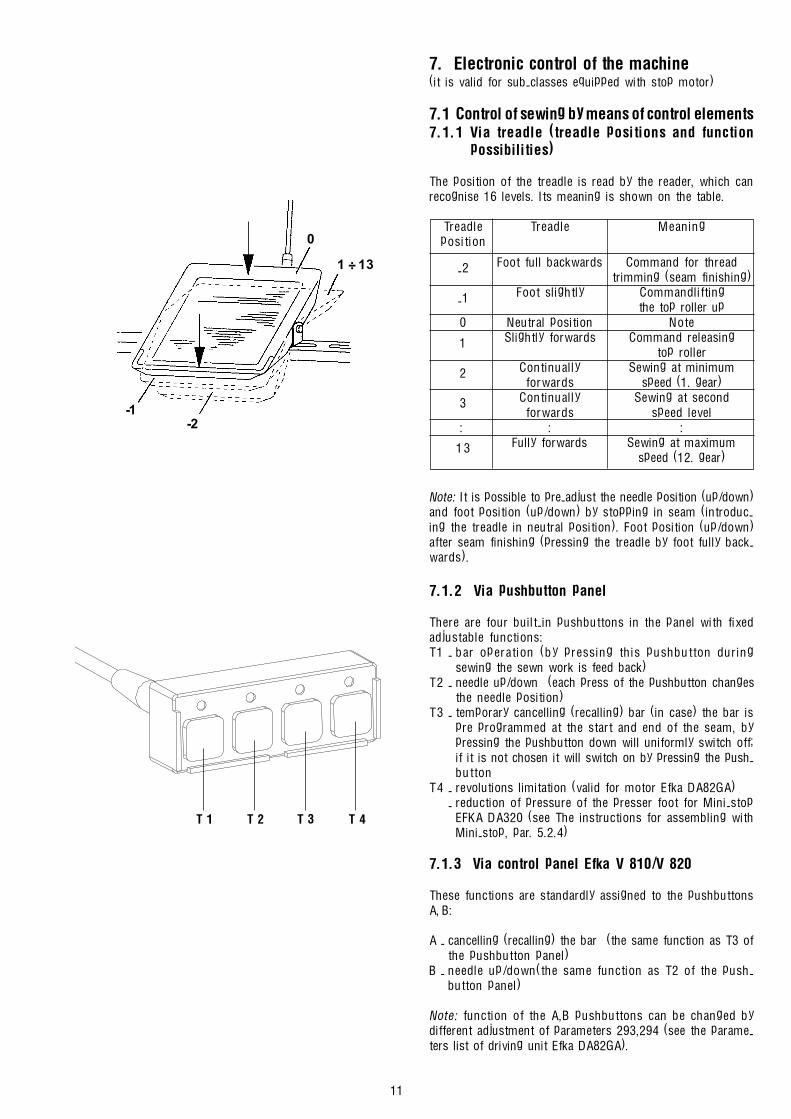
7. Electronic control of the machine(it is valid for sub-classes equipped with stop motor)
7.1 Control of sewing by means of control elements7.1.1 Via treadle (treadle positions and function
possibilities)
The position of the treadle is read by the reader, which canrecognise 16 levels. Its meaning is shown on the table.
Treadle Treadle Meaningposition
-2 Foot full backwards Command for threadtrimming (seam finishing)
-1 Foot slightly Commandliftingthe top roller up
0 Neutral position Note
1 Slightly forwards Command releasingtop roller
2 Continually Sewing at minimumforwards speed (1. gear)
3 Continually Sewing at secondforwards speed level
: : :
13 Fully forwards Sewing at maximumspeed (12. gear)
Note: It is possible to pre-adjust the needle position (up/down)and foot position (up/down) by stopping in seam (introduc-ing the treadle in neutral position). Foot position (up/down)after seam finishing (pressing the treadle by foot fully back-wards).
7.1.2 Via pushbutton panel
There are four built-in pushbuttons in the panel with fixedadjustable functions:T1 - bar operation (by pressing this pushbutton during
sewing the sewn work is feed back)T2 - needle up/down (each press of the pushbutton changes
the needle position)T3 - temporary cancelling (recalling) bar (in case) the bar is
pre programmed at the start and end of the seam, bypressing the pushbutton down will uniformly switch off;if it is not chosen it will switch on by pressing the push-button
T4 - revolutions limitation (valid for motor Efka DA82GA)- reduction of pressure of the presser foot for Mini-stop
EFKA DA320 (see The instructions for assembling withMini-stop, par. 5.2.4)
7.1.3 Via control panel Efka V 810/V 820
These functions are standardly assigned to the pushbuttonsA, B:
A - cancelling (recalling) the bar (the same function as T3 ofthe pushbutton panel)
B - needle up/down(the same function as T2 of the push-button panel)
Note: function of the A,B pushbuttons can be changed bydifferent adjustment of parameters 293,294 (see the parame-ters list of driving unit Efka DA82GA).
T 1 T 2 T 3 T 4
1 ÷ 13
0
-1-2

12
7.2 Adjustment of automatic functions via controlpanel for stop motor
7.2.1 By using stop motor Efka with panel V 810Functioning pushbuttons engagement:Pushbutton P Recalling and program mode terminationPushbutton E Confirmation of program mode changesPushbutton + Increase of value displayed in program
modePushbutton - Decreasing value displayed in program
modePushbutton 1 Start bar SINGLE/DOUBLE/OFFPushbutton 2 End bar SINGLE/DOUBLE/OFFPushbutton 3 Automatic top roller lifting after stopping
at the seam ON/OFFAutomatic top roller lifting after threadtrimming (end of seam) ON/OFFAutomatic presser foot lifting afterthread trimming (end of seam) ON/OFFAutomatic reduction of pressure of thepresser foot ON/OFF (only for DC 1550/DA320; see The instructions for assem-bling with Mini-stop, par. 5.2.4)
Pushbutton 4 Basic position of needle UP/DOWNPushbutton A For cancelling respectively recalling
the barPushbutton B For switch over the needle position
UP/DOWN respective shift pushbuttonin program mode
Symbol C Connection of automatic revolutionsSymbol D Connection of lighting barrierSymbol E The machine is runningSymbol F The revolutions limitation switch onSymbol G Connection of lower thread controller,
flashing light indicator symbol whenthe threads supply on the bobbin isrunning out
The arrows on the display indicate switching the functionswhich are displayed by symbols above the pushbuttons on.
7.2.1.1 Adjustment by means of buttons with fixed settingfunction
Note: It is important to finish the seam in order to reacheffective button pressing (press the treadle fully backwardsdown).Setting start bar:Drive enables sewing start bar automatically. It is necessary tochoose the type (single, double, off) and number of stitcheswhich will be sewn forwards and backwards.The arrow above its symbol shows the type of bar (chosen bygradually pressing pushbutton 1). It will be displayedfollowing after pressing pushbutton 1.Arv (SAv) XXX - number of stitches of start (fancy) bar for-wards orArr (SAr) XXX - number of stitches of start (fancy) bar back-wards) for about 3 sec.At this time you can change the number of stitches by gra-dually pressing the pushbutton + or -.By setting the treadle to its zero position during the sewing ofthe start bar (par. 215 - OFF), you stop the machine at thecompletion of the start bar. You can then switch on the sewnwork cutter.Setting end bar:The same applies to the start bar (setting by the means ofpushbutton 2).Erv (SEv) XXX - end (fancy) bar number of stitches forwardsErr (SEr) XXX - end (fancy) bar number of stitches backwardsNote: The last section of end bar must have at least 3 stitches.

13
Foot position adjustment by stopping at the seam (by neutralposition of treadle) and after finishing seam (by neutral posi-tion of treadle):Setting is by means of pushbutton 3, arrow indication abovethe corresponding symbol.
Needle position adjustment by stopping at the seam:Setting is by means of pushbutton 4.
7.2.1.2 Setting by means of parametersDrive memory contains the parameters which enables sewingsystem tuning. These parameters have exact meaning andthey are divided into 3 levels. Further parameters which areavailable only for operation will be quoted. Each parameterhas its (sequence) number and value.
General procedure by changing parameters of operation level:- switch the main switch on or finish the seam by pressing the
treadle fully backwards down- press pushbutton P on the panel V 810- it will be displayed on the display F 000 (000 it is the number
of parameter)- by several times pressing + (or -) set the requested number
of parameter- push pushbutton E down and it will be shown the value of
parameter on the display- you can change the value by means of pushbutton + or �- by pushing pushbutton E down you will change the sequence
to the following number of parameter- by pushing pushbutton P down you will leave the mode of
changing parameters
Note: 1. For permanent memory storing of changed pa-rameter, it is necessary to press treadle forwardsdown after changing of parameters.
2. Mode of changing parameters is possible only af-ter finishing of the seam.
Number of stitches in bars:Number of stitches is stored in parameter�s number.
No. of parameter Value range Descriptionof parameter of parameters
000(080) 0-254 Number of stitches of start (fancy) bar forwards
001(081) 0-254 Number of stitches ofstart (fancy)bar backwards
002(082) 0-254 Number of stitches ofend (fancy) bar backwards
003(083) 0-254 Number of stitches of end (fancy)bar forwards
Sewing according to sewing program:Drive with panel V810 automatically enables sewing of 1 seamwith setting number of stitches. It is necessary to set in corre-sponding number of stitches, and initialisation of sewing pro-gram.
No. of parameter Value range Descriptionof parameter of parameters
007 0-254 Number of stitches
015 ON/OFF ON/OFF sewing undersewing program

14
ON/OFF thread trimmer:
No. of parameter Value range Descriptionof parameter of parameters
013 ON/OFF Thread trimmerON/OFF
7.2.2 By using stopmotor Efka with panel V 820Functioning pushbuttons engagement:Pushbutton P Call and termination of programming modePushbutton E Confirmation when changing programming
modePushbutton + Increasing the value displayed in program-
mingmodePushbutton - Reducing the value displayed in program-
ming modePushbutton 1 Start bar SINGLE/DOUBLE/OFFPushbutton 2 Stitch counting FORWARD/BACK/OFFPushbutton 3 Light barrier function
LIGHT-DARK/DARK-LIGHT/OFFPushbutton 4 End bar
SINGLE/DOUBLE/OFFPushbutton 5 Function
TRIMMING/TRIMMING+EJECTOR/OFFPushbutton 6 Automatic top roller lifting after having
stopped inside the seam ON/OFFAutomatic top roller lifting after trimmingON/OFFAutomatic presser foot lifting after threadtrimming (end of seam) ON/OFFAutomatic reduction of pressure of thepresser foot ON/OFF (only for DC 1550/DA320; see The instructions for assem-bling with Mini-stop, par. 5.2.4)
Pushbutton 7 Basic needle position UP/DOWNPushbutton 8 Lower thread waste controlling ON/OFFPushbutton 9 Operation pushbutton - programmablePushbutton 0 Programming/processing of 40 possible
sewing sections (seams)Pushbutton A For cancelling or calling the barPushbutton B For switching needle position UP/DOWN,
resp. shifting pushbutton in the program-ming mode
Symbol C Designating symbol C for code numberSymbol D Designating symbol F for parameter
numberSymbol E Programme number in TEACH IN modeSymbol F Seam number in TEACH IN modeSymbol G Run blocking ONSymbol H Blocked insertion by pushbuttonSymbol I Fault reportingSymbol J Insertion of stitch number in TEACH IN
modeSymbol K Connected lower thread controller,
flashing symbol when running out threadreserve on bobbin
Symbol L Limitation of revolutions ONSymbol M Right needle disconnectedsymbol N Evening stitches for light barriee in the
TEACH IN mode
A B
C D E F G H I J K L M N O P Q

15
Symbol O Machine is runningSymbol P Automatic revolutions ONSymbol Q Left needle disconnected
The arrows on the display indicate switching the functionswhich are displayed by symbols above the pushbuttons on.
7.2.2.1 Adjustment by means of buttons with fixed settingfunction
Note: It is important to finish the seam in order to reacheffective button pressing (press the treadle fully backwardsdown).Setting start bar:Drive enables sewing start bar automatically. It is necessary tochoose the type (single, double, off) and number of stitcheswhich will be sewn forwards and backwards.The arrow above its symbol shows the type of bar (chosen bygradually pressing pushbutton 1). It will be displayedfollowing after pressing pushbutton 1.Arv (SAv) XXX - number of stitches of start (fancy) bar for-wards orArr (SAr) XXX - number of stitches of start (fancy) bar back-wards for about 3 sec.At this time you can change the number of stitches by gra-dually pressing the pushbutton + or -.Setting end bar:The same applies to the start bar (setting by the means ofpushbutton 4).Erv (SEv) XXX - end (fancy) bar number of stitches forwardsErr (SEr) XXX - end (fancy) bar number of stitches backwards
Note: The last section of end bar must have at least 3 stitches.
Foot position adjustment by stopping at the seam (by neutralposition of treadle) and after finishing seam (by neutral posi-tion of treadle):Setting is by means of pushbutton 6, arrow indication abovethe corresponding symbol.
Needle position adjustment by stopping at the seam:Setting is by means of pushbutton 7.Trimming switched ON/OFF:To be set using pushbutton 5.Sewing programme ON:To be switched on using pushbutton 0.Switching ON/OFF the function of the pushbutton F:The pushbutton F on panel can have assigned one of thefollowing functions: Sst - softstart
SrS - fancy barFrd - reverse angle after trimming
7.2.2.2 Setting by means of parametersDrive memory contains the parameters which enables sewingsystem tuning. These parameters have exact meaning andthey are divided into 3 levels. Further parameters which areavailable only for operation will be quoted. Each parameterhas its (sequence) number and value.General procedure by changing parameters of operation level:- switch the main switch on or finish the seam by pressing the
treadle fully backwards down- press pushbutton P on the panel V 820- on the display there is no data shown- by depressing the pushbutton E several times, set the
required parameter (without having displayed the parameternumber)
- you can change the value using pushbuttons + or -- by depressing the pushbutton E you will pass in the given
sequence to the following parameter- by depressing the pushbutton P down you will leave the
mode of changing parameters
A B
C D E F G H I J K L M N O P Q

16
1
4
2
3
A B
C D E F G H I J K L M N O P Q Note: 1. For permanent memory storing of changed pa-rameter, it is necessary to press treadle forwardsdown after changing of parameters.
2. Mode of changing parameters is possible only af-ter finishing of the seam.
Number of stitches in bars:Number of stitches is stored in parameter�s number.
No. of parameter Value range Descriptionof parameter of parameters
000(080) 0-254 Number of stitches of start (fancy) bar forwards
001(081) 0-254 Number of stitches ofstart (fancy) bar backwards
002(082) 0-254 Number of stitches ofend (fancy) bar backwards
003(083) 0-254 Number of stitches of end (fancy) bar forwards
The drive with the panel V 820 enables sewing automaticallyup to 40 seams distributed up into eight programmes with thegiven stitch numbers and sewing direction (forwards/rear-wards). For more detailed information see the original drivinginstructions.
8. Maintenance
Caution! Risk of injury!Maintenance work can only be carried out whenthe machine is off and the motor stops.
Maintenance work which must be carried out and the intervalsbetween them and set out in the following table.
Maintenance work Interval
Removing throat plate and its cleaning.Cleaning of circular feed dog, hook and spacearound feeding wheel of material and threadresidues. To clean it, use brush. It is prohibitedto use compressed air for cleaning without 1 dayprotective guards preventing injury of persons
with flying impurities.Hook lubrication - (one drop of oil).
Checking the oil level in the hooklubrication oil tank. 1 week
Checking the oil level in the oil tanksof the central distribution.
1 monthRegreasing of the greasing spotsof the trimming system (pins with felt).
For the lubrication of this machine Esso SP-NK 10, DA 10 oran equivalent quality lubricating oil is recommended (viscossityat 40° C: 10 mm2/s; flash point: 150°C).The oil tanks (1, 2, 3) of the central distribution is to be filledthe hole (4) up to the mark max.

17
Trouble
1. Upper thread breaking.
2. Lower thread breaking.
3. Skipped stitches at the seam begin-ning after previous thread trimming.
4. Stitch skipping.
Cause
1.1 Incorrect threading of the upperthread.
1.2 Excessive thread tension.1.3 Needle incorrectly inserted or da-
maged.1.4 Needle thickness does not suit to
that of thread or sewn material.1.5 Hook point sticks the thread.
1.6 Needle thread excessively elastic.
1.7 Low quality thread.1.8 Needle thickness unsuitable for the
hole in the throat plate insert.1.9 Damaged throat plate insert.
1.10 Incorrect setting of opening bob-bin case lifter (little opening).
2.1 Incorrect threading.2.2 Damaged bobbin.
3.1 Short thread end in needle aftertrimming (thread too tensioned inthe moment of trimming).
3.2 Excessive thread tension.
3.3 Upper thread not squeezed, at thefirst needle piercing, betweensewn material and rear edge ofpiercing hole.
3.4 Upper thread incorrectly caught bymovable trimming knife. Lumps ofthread remaining in hook space.
3.5 Needle too thick with regard tothickness of thread and sewn ma-terial.
4.1 Needle incorrectly inserted.4.2 Too big distance between needle
and hook point.4.3 Incorrectly set needle hook timing
or needle height.4.4 Excessively elastic material or ex-
cessively elastic thread.
4.5 Damaged hook point.
Method of troubleshooting
Thread the upper thread according to NP,par. 6.1.Set the tension according to NP, par. 6.4.Replace needle according to NP, par. 6.5.
Use a thicker needle.
Set distance between hook and needleaccording to SK, par. 3.1.3 and 3.1.5.Increase the hook timing and set theneedle bar height according to SK, par.3.2.3.Replace thread.Replace insert.
Replace insert.Set according to SK, par. 3.1.6.
Thread according to NP, par. 6.3.Replace bobbin.
Thread upper thread according to NP,par. 6.1. Reduce tension of pretensionunit according to NP, par. 6.4. Accelerateslightly OFF position of main tensioneraccording to SK, par. 4.9; NP, part B, par.5.2.2, 5.3.2; Mini-stop, par. 5.2.5 - pa-rameter 192.Set thread tension according to NP, par.6.4.Set needle feeding in such a way, so that,with the maximum stitch length, the nee-dle almost touches the rear edge of throatplate insert accordin to SK, par. 3.2.5.Reduce height of wheel feeder accord-ing to SK, par. 3.5.3.2.1.Put nearer top roller to needle and shiftit rearwards according to SK, par. 3.6.6.2.Set correctly hook opening according toSK, par. 3.1.6 and adjust setting of trim-ming cam according to SK, par. 4.3.Use thinner needle.
Insert needle according to NP, par. 6.5.Set according to SK, par. 3.1.3 and 3.1.5.
Set according to SK, par. 3.1.4 and 3.2.3.
Increase timing as needed and set theneedle bar height according to SK, par.3.2.3.Replace hook.
Operating instructions for eventual trouble shooting
Meaning of abbreviations: NP - Instruction manualSK - Instructions for service
Note: When the machine is driven by a stop motor, it is indispensable to check up, before starting its repair, the setting of itsparameters according to NP, part B, par. 5.
18
5.1 Lower thread tension.5.2 Incorrect threading and tension
setting of upper thread.
6.1 Upper thread out of tensioningdishes.
6.2 Opening bobbin case lifter incor-rectly set (it opens too little).
6.3 Wheel feeder too low - difficultpassage of thread between sewnmaterial and throat plate.
6.4 Upper thread insufficiently tensio-ned when passing through hook.
7.1 Low tension of upper and lowerthreads.
7.2 Upper thread insufficiently tensio-ned when passing through hook.
7.3 Thin needle with regard to threadthickness.
8.1 Thread tension to high for sewnmaterial.
9.1 Overrun safety clutch against hookoverload.
10.1 Wheel feeder too low (especiallywhen sewing soft and thick ma-terials).
10.2 Feeder teeth unsuitable (too fine)for sewn material.
10.3 Wheel feeder driving chain tootensioned - blocked feeding.
11.1 Incorrect lower thread threadingwhen replacing hook bobbin -lower thread caught by hook point.
11.2 Upper thread out of tensioningdishes and 2x caught by hookpoint.
11.3 Insufficient gap between needleand piercing hole from hook side.
12.1 Incorrectly threaded thread.
12.2 Upper thread excessively brakedwhen moving upwards due to thinneedle, thick elastic material, lowfeeder position, low thread tension.
12.3 Tensioner electromagnet cutssoon main tensioner during trim-ming.
12.4 Fixed trimming knife does not fitwith all its width against movableknife.
12.5 Movable knife does not run overmovable knife edge.
12.6 During trimming cycle, safetyclutch against hook overload getsdisengaged.
13.1 Incorrect movable knife path set-ting.
Set according to NP, par. 6.4.Thread according to NP, par. 6.1 setaccording to NP, par. 6.4.
Thread correctly according to NP par. 6.1.
Set according to SK, par. 3.1.6.
Set wheel feeder height according to SK,par. 3.5.3.2.1.
Shift thread limiter to the top accordingto SK, par. 3.4.5 or by more than the valuequoted there.
Set tension according to NP, par. 6.4.
Shift thread limiter to the top accordingto SK, par. 3.4.5 or more than the valuequoted there.Use a thicker needle.
Reduce tension of both threads.
Engage correctly clutch according to NP,par. 6.10.
Raise feeder more from throat plateaccording to SK, par. 3.5.3.2.1.
Use feeder with 0.6 mm teeth pitch.Replace according to SK, par. 3.5.3.2.2.Set chain tension according to SK, par.3.5.3.2.1.
Thread lower thread according to NP, par.6.3.
Thread upper thread according to NP, par.6.1.
Set side position of the throat plate postaccording to SK par. 3.3.3.
Thread the thread according to NP, par.6.1.Insert thicker needle according to NP, par.6.5.Lift wheel feeder according to SK, par.3.5.3.2.1.Delay position of cutting the main ten-sioner according to SK, par. 4.9 and ac-cording NP, part B, par. 5.2.2, 5.3.2; Mini-stop, par. 5.2.5 - parameter 192.Set knives according to SK, par. 4.7.
Set knife according to SK, par. 4.5.
Increase clutch disengaging momentaccording SK, par. 3.9.2.
Set knife according to SK, par. 4.5.
5. Incorrect stitch locking. Threads arelocked on top side of sewn material.
6. Incorrect stitch locking. Threads arelocked on bottom side of sewnmaterial and increasing of tensionis of upper thread no help.
7. Stitches insufficiently tightened andwith irregular positioning. Threadunravelled.
8. Sewn material wavy in seam.
9. Machine does not feed or is feedingslowly or in reverse sense.
10. Difficult and iregular machine feed.
11. Hook blocked.
12. No upper thread trimming.
13. No lower thread trimming.
19
14. Second and third stitches incor-rectly locked at the beginning ofsewing after previous trimming.
15. Pinched out cutting edge of cuttingknife.
16. Poor cutting quality.
17. Uneven stitch length of direct seam.
13.2 Short movable knife path.
13.3 Incorrect cam setting.13.4 Incorrect trimming knife height
setting.
14.1 Incorrect setting of lower hookthread retaining spring.
15.1 Pinching out of cutting edge dur-ing the knife exchange: The fixingscrews failed to be lightly tightenedbefore the cutting edge has beenset on the gauge.
15.2 Faulty lateral position of the knifein relation to the throat plate insert:excessive pressure between theknife and the insert.
15.3 The knife collides with the sewnwork guide.
16.1 Play between the cutting edges ofthe knife and of the throat plate in-sert.
16.2 Slow run of work cutter motor:faulty connection of supply trans-former.
16.3 Blunt knife.
17.1 Blunt knife.17.2 Sewing speed too great for the cho-
sen stitch length.17.3 Insufficient height of lower wheel
feed over the throat plate.
Increase path by correct fork settingaccording to SK, par. 4.4.Set cam according to SK, par. 4.3.Set height according to SK, par. 4.6.
Set spring according to SK, par. 4.8.
Fix the knife according to NP, par. 6.15.
a) Switch off the machine, set the knifeto its lower position, loosen the screwsof the throat plate and retighen them.b) Set the lateral position of the knife asin SK.Adjust the guide according to NP, par.6.14.
a) Loosen the throat plat screws, pressthe throat plate against the knife andretighten the screws.b) Set the lateral position of the knifeaccording to SK.Change the branch of primary winding ofthe transformer according to NP, part B,par. 4.8.Exchange the knife.
Exchange the knife.Reduce the sewing speed according toNP, par. 5.Lift the feed wheel according to SK, par.3.5.3.2.1.

Contents - part B1 - The instructions for assembling with standard drives
1. Safety instructions ............................................................................................................................................................. 1
2. The way of machine supply ............................................................................................................................................... 1
2.1 Complete head with accessories ............................................................................................................................ 1
2.2 Stand ........................................................................................................................................................................ 12.3 Motor .......................................................................................................................................................................................... 1
2.4 Motor pulley ............................................................................................................................................................. 2
3. Table top ........................................................................................................................................................................... 3
4. Machine assembly ............................................................................................................................................................ 3
4.1 Stand frame assembly ............................................................................................................................................................ 3
4.2 Assembly of components on the bottom of table top ............................................................................................. 44.2.1 Power supply 1 x 230 V - DC motor ............................................................................................................ 44.2.2 Power supply 3 x 400 V - five wire power distribution, power supply 3 x 230 V - four wire or
five wire power distribution ....................................................................................................................................... 54.2.3 Power supply 3 x 400 V - four wire power distribution plus 1 x 230 V - two wire cabel ................................... 5
4.3 Assembly of a table top on a stand frame, assembly of oil tank .......................................................................... 6
4.4 Assembly of machine head onto a stand ............................................................................................................... 6
4.5 Assembly of motor pulley, belt, belt covers, hand wheel ...................................................................................... 7
4.6 Assembly of treadle rod, setting rod and of position sensor, knee lever .............................................................. 7
4.7 Electrical connection of machine head to the stopmotor ............................................................................................. 84.7.1 Connecting cable ......................................................................................................................................................... 84.7.2 The actual electrical connection ................................................................................................................................ 94.7.3 Fastening upper cover belt, position reader, control panel of stopmotor and thread stand ........................... 10
4.8 Wiring of the work trimmer ....................................................................................................................................................114.8.1 For machines having the Efka stopmotor ................................................................................................................114.8.2 For machine having the clutch motor ........................................................................................................................11
5. Basic setting of stopmotor and position reader ......................................................................................................................... 12
5.1 Generally ................................................................................................................................................................................. 12
5.2 Stopmotor setting S359 600045 XXX - EFKA DC 1600/DA82GA ................................................................................... 125.2.1 Setting position reader ...............................................................................................................................................125.2.2 Changes of setting parameters of stopmotor setting considering original producer setting .......................... 13
5.3 Stopmotor setting S359 600052 XX - EFKA VD 552/6F82FAand S359 600056 XX - EFKA VD 554/6F82FA ....................................................................................................................135.3.1 Setting position reader ...............................................................................................................................................135.3.2 Changes of setting parameters of stopmotor setting considering original producer setting ........................... 13
6. Examination of sewing ................................................................................................................................................................... 13
Supplement ....................................................................................................................................................................................... 14
1
Part B1 - The instructions for assembling with standard drives
1. Safety instructions
Caution !Assembly of the machine must only be carried out by appropriately trained technician.Any operations to be performed on the electric installation of the sewing machine are to be done only by a compe-tent electrician.
2. The way of machine supply
The contents of supply will be determined in agreement between the supplier and buyer. There are following possibilities:
2.1 Complete head with accessoriesIn this case the supply contains:- Complete head.- Chosen spare parts in the bag under the presser element (see parts indicated * in catalogue of spare parts).- Standard accessories (it contains tools-see module in catalogue of spare parts).- Special accessories (it contains some components of a stand and upper belt cover-see module in catalogue of spare
parts).The supply like this is not complete. Buyer will provide missing components himself or he can put in an extra order to getthem according to the following paragraphs.
2.2 StandDelivery contains components of a stand, however, without components of a stand included in special accessories sup-plied with machine head (see par.2.1) and without any electrical components.If it hasn�t been agreed otherwise, the stand is supplied in separate pieces. If the assembled stand is asked, specialaccessories are used from head supply.
Stand (ordered number S400 010000) contains following items:
Equipment for foot lifting by treadle:
2.3 MotorThe supply contains its own motor, switch - circuit breaker, all cabling (except of the plug) and material for connection. Itcan contain a control panel according to the type of motor. If it hasn�t been agreed otherwise, it is supplied in separatepieces. A machine without trimming is equipped with clutch lever motor. However if positioning is asked or electromagneticfoot lifting or electromagnetic reverse stitching (bartacking) the machine without trimming must be equipped with stopmotor.
MG55 000501 Stand frameMG53 002501 Big treadleMG53 007511 Set of parts for a standS615 000320 Table top
S058 000450 Small treadleS980 060028 Foot lifting rod

2
Motors are chosen according to the following table:
* Control panel S359 600038/V810 or S359 600050/V820 it is possible to order for setting the stop motor, however, it isnot included in supply of the stopmotor and it has to be ordered separately.
Above mentioned stop motors were tested in the machine and they meet functional requirements. Other typesof stop motors can have but need not have suitable parameters. Producer does not recommend using the otherstopmotor without testing.
2.4 Motor pulleyBy stopmotor EFKA DC 1600/DA82GA is revolutions are set continuously by electronics.
The diameter of the motor pulley in mm must be by asynchronous motors according to the following quotation:
Diameter of pulley = 71 x sewing speed (st/min)
motor revolutions (rev./min)
The smallest diameter of pulley is 42 mm considering used V-belt. Belt cover on the motor limits the biggest diameterof pulley to 127 mm.The pulley for the maximum or other sewing speed will be supplied on express wish of the customer.
Motor pulley diameter
Sewing speed of machines: standard 1)
Mains voltage frequency: 50 Hz
1) When the customer will not order anything else, he will get a pulley for standard sewing speed. Owing to a limitedassortment of pulleys, the effective sewing speed may slightly differ from that declared and quoted in the column.
2) The table gives effective pulley diameter which is by 4 to 5 mm lower than the outer diameter.
Note.: The effective diameter of the hand wheel pulley is 71 mm.
Machine Ordered Name Diameter Machine rev. Approx. specificationsubclass number of pulley max./min
50 Hz/60 HzX11 S359 600030 63 FIR 1148 63 2500/3000 asynchronous clutch motor; switch-circuit breakerX21 S359 600030 50 3 x 400/230 V, 50 2000/2400 with cabling; connection material
S359 600030 42 2800 RPM, 50 Hz 42 1600/2000
S359 600031 75 FIR 1147F 75 1500/1800 asynchronous clutch motor; switch-circuit breakerS359 600031 63 3 x 400/230 V, 63 1200/1500 with cabling; connection materialS359 600031 42 1400 RPM, 50 Hz 42 800/1000
X12 S359 600045 810 Stopmotor EFKA 58 adjustable DC motor (AC servo) control panel V810;X22 DC 1600/DA82GA mains switch with cabling; connection materialX4X 1 x 230 V, 50/60 HzX5X S359 600045 820 58 adjustable DC motor (AC servo) control panel V820;
mains switch with cabling; connection material
S359 600052 63 Stopmotor EFKA * 63 2500/3000 asynchronous stopmotor with friction clutch andS359 600052 50 VD 552/6F82FA 50 2000/2400 brake; switch-circuit breaker; connection materialS359 600052 42 3 x 400/230 V, 42 1600/2000
2800 RPM, 50/60 HzS359 600056 75 Stopmotor EFKA * 75 1500/1800 asynchronous stopmotor with friction clutch andS359 600056 63 VD 554/6F82FA 63 1200/1500 brake; switch-circuit breaker; connection materialS359 600056 42 3 x 400/230 V, 42 800/1000
1400 RPM, 50/60 Hz
Ordered number/motor pulley diameter 2)
Model Sewing EFKA DC 1600/ EFKA VD 552/ FIR 1148/552/3 EFKA VD 554/ FIR 1147F/554/3speed DA82GA 3312 6F82FA 6F82FA(SPM) 4000 RPM 2800 RPM 2800 RPM 1400 RPM 1400 RPM
4182-1XX-100 2500S359 600052 63/ø 63 S359 600030 63/ø 63 - -
-200 2500S359 600045 810/ø 58
-300 1600S359 600045 820/ø 58
S359 600052 42/ø 42 S359 600030 42/ø 42 S359 600056 75/ø 75 S359 600031 75/ø 75

3
Sewing speed of machines: standard 1)
Mains voltage frequency: 60 Hz
When the customer requires another sewing speed than standard, he may additionally order another pulley according to thefollowing table:
3. Table top
In case buyer will provide his own table top its drawing isshown in supplement.
4. Machine assembly
It is described machine assembly with stand here which issupplied in separate pieces. Otherwise use these instructionsadequate.
4.1 Stand frame assembly
A frame is assembled according to the picture.
Ordered number/motor pulley diameter 2)
Model Sewing EFKA DC 1600/ EFKA VD 552/ FIR 1148/552/3 EFKA VD 554/ FIR 1147F/554/3speed DA82GA 3312 6F82FA 6F82FA(SPM) 4000 RPM 3360 RPM 3360 RPM 1680 RPM 1680 RPM
4182-1XX-100 2500S359 600052 50/ø 50 S359 600030 50/ø 50 - -
-200 2500S359 600045 810/ø 58
-300 1600S359 600045 820/ø 58
- - S359 600056 63/ø 63 S359 600031 63/ø 63
Motor Sewing speed Sewing speed Diameter of Ordered50 Hz 60 Hz pulley (mm) number
FIR 1148/552/3 1660 1990 42 S980 045548EFKA VD552 1850 2220 47 S980 045377
1970 2370 50 S980 0454912130 2560 54 S980 0453612290 2740 58 S980 0454722480 2980 63 S980 0453782640 3170 67 S980 0454762760 3310 70 S980 0453702960 75 S980 0453843150 80 S980 0454793350 85 S980 045480
FIR 1147F/554/3 830 990 42 S980 045548EFKA VD554 930 1110 47 S980 045377
990 1180 50 S980 0454911060 1280 54 S980 0453611140 1370 58 S980 0454721240 1490 63 S980 0453781320 1590 67 S980 0454761380 1660 70 S980 0453701480 1770 75 S980 0453841580 1890 80 S980 0454791680 2010 85 S980 0454801770 2130 90 S980 0454811970 2370 100 S980 0454832090 2510 106 S980 0454842210 2650 112 S980 0454852500 3010 127 S980 045337
4
4.2 Assembly of components on the bottom of table top
- Put down antiskid (rubber) bands on the stand frame.- Turn the table top up side down and put it down on prepared bands.- By means of screws scerw the drawer (1)down.- Nail down the rubber stop (2).- By means of screws fasten transformer for lighting (3) if available.- By means of screws fastened transformer for trimming (4) if available.- By means of screws fasten switch � circuit breaker (5).- Screw the motor holder down (6) (possibly motor). Lever clutch motor is assembled into the holes (A). Stopmotor into holes (B).- By means of clips (7) install transmission line of heavy current conductors. Connection is different from the type of motor,
supply voltage and number of conductors of electric supply. In case of quad (four wire) supply 3 x 400 V, transformer forlighting must be supplied with separate supply cable 1 x 230 V.
Caution!The voltage in the mains must be in conformity with the voltage indicated on the drive plate.
Caution!The transformer of the bulb for the sewing area is not switched off by the main switch (EN 60204-3-1). Beforeproceeding to any repair operation in the transformer box (such as a fuse exchange) the plug categorically must betaken out of the socket. Such operations may be carried out only by persons with adequate electrotechnical skill.
Choose the suitable variant according to the pictures:
4.2.1 Power supply 1 x 230 V - DC motor
Circuit layout - Europe Circuit layout - America
Transformer for sewing area bulb
Power for sewn work cutterMachine stand
Machine head
Transformer for sewing area bulb
Power for sewn work cutterMachine stand
Machine head
A
B
5
16
170
5
60
13
55
6274
1 3 5
5 5
3
4
3
4
5
4.2.2 Power supply 3 x 400 V - five wire power distribution, power supply 3 x 230 V - four wire orfive wire power distribution
4.2.3 Power supply 3 x 400 V - four wire power distribution plus 1 x 230 V - two wire cable
Circuit layout - Europe Circuit layout - America
Circuit layout
Transformer for sewing area bulb
Power for sewn work cutter Machine stand
Machine head
Transformer for sewing area bulb
Power for sewn work cutterMachine stand
Machine head
Transformer for sewing area bulb
Power for sewn work cutterMachine stand
Machine head
A
B
5
16
170
5
60
13
55
6274
1 3 5
5
3
4
5
3
4
5
3
4
A
B
5
16
170
60
13
55
5
6274
1 3 5
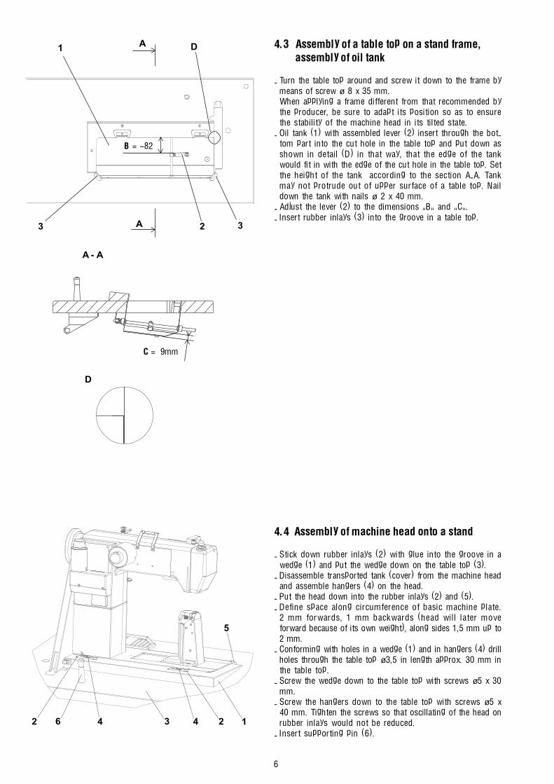
6
4.3 Assembly of a table top on a stand frame,assembly of oil tank
- Turn the table top around and screw it down to the frame bymeans of screw ø 8 x 35 mm.When applying a frame different from that recommended bythe producer, be sure to adapt its position so as to ensurethe stability of the machine head in its tilted state.
- Oil tank (1) with assembled lever (2) insert through the bot-tom part into the cut hole in the table top and put down asshown in detail (D) in that way, that the edge of the tankwould fit in with the edge of the cut hole in the table top. Setthe height of the tank according to the section A-A. Tankmay not protrude out of upper surface of a table top. Naildown the tank with nails ø 2 x 40 mm.
- Adjust the lever (2) to the dimensions �B� and �C�.- Insert rubber inlays (3) into the groove in a table top.
4.4 Assembly of machine head onto a stand
- Stick down rubber inlays (2) with glue into the groove in awedge (1) and put the wedge down on the table top (3).
- Disassemble transported tank (cover) from the machine headand assemble hangers (4) on the head.
- Put the head down into the rubber inlays (2) and (5).- Define space along circumference of basic machine plate.
2 mm forwards, 1 mm backwards (head will later moveforward because of its own weight), along sides 1,5 mm up to2 mm.
- Conforming with holes in a wedge (1) and in hangers (4) drillholes through the table top ø3,5 in length approx. 30 mm inthe table top.
- Screw the wedge down to the table top with screws ø5 x 30mm.
- Screw the hangers down to the table top with screws ø5 x40 mm. Tighten the screws so that oscillating of the head onrubber inlays would not be reduced.
- Insert supporting pin (6).
A - A
1243462
5
B = ~82
A
A 33
D1
2
C = 9mm
D
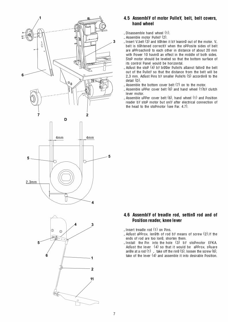
7
4.5 Assembly of motor pulley, belt, belt covers,hand wheel
- Disassemble hand wheel (1).- Assemble motor pulley (2).- Insert V-belt (3) and tighten it by leaning out of the motor. V-
belt is tightened correctly when the opposite sides of beltare approaching to each other in distance of about 20 mmwith power 10 having an effect in the middle of both sides.Stop motor should be leveled so that the bottom surface ofits control panel would be horizontal.
- Adjust the stop (4) by bigger pulleys against falling the beltout of the pulley so that the distance from the belt will be2-3 mm. Adjust pins by smaller pulleys (5) according to thedetail (D).
- Assemble the bottom cover belt (7) on to the motor.- Assemble upper cover belt (6) and hand wheel (1)by clutch
lever motor.- Assemble upper cover belt (6), hand wheel (1) and position
reader by stop motor but only after electrical connection ofthe head to the stopmotor (see par. 4.7).
4.6 Assembly of treadle rod, setting rod and ofposition reader, knee lever
- Insert treadle rod (1) on pins.- Adjust approx. length of rod by means of screw (2).If the
ends of rod are too long, shorten them.- Install the pin into the hole (3) by stopmotor EFKA.
Adjust the lever (4) so that it would be approx. squareangle at a rod (1) - take off the ring (5), loosen the screw (6),take of the lever (4) and assemble it into desirable position.
11
2
1
34
6
5
3
1
2
6
7
55
4
4mm4mm
2-3mm
D

8
- Loosen the screws (9) by clutch lever motor and turn themotor with lever in such a way that the lever (10) would be indirection of the rod axis (1).
- Adjust angular turning of treadle (11). The position of trea-dle is correctly adjusted if there is a square angle at the shin-bone of the operator to the treadle.
- Fasten knee lever (12) onto the shaft (13) and adjust it in aposition that it is shown in the picture (slightly leant out).
4.7 Electrical connection of machine head to the stopmotor
4.7.1 Connecting cable
Together with the machine head there is supplied a connecting cable for the following drives:EFKA DC 1600/DA82GA 3311 and higherEFKA VD 552/6F82FA 2315 and higherEFKA VD 554/6F82FAWhen there is no drive specified, a cable without any connecting power plug is supplied (mind the caution 2.3).For the information sake, there are given the respective circuit layout.The colours are indicated with numbers in brackets (6 � green, 7 � blue, 8 � pink, 9 � black, 10 � white, 11 � violet, 12 � yellow,13 � red, 14 � grey, 15 � brown). Included insulating covers PVC (5) are put on the bunches and they are put together withremaining part of cable insulation by means of contracted tube (4) (it is heated up with fire of lighter).
Power connecting cable is marked off with dotted line in circuit layout.
Stopmotor S359 600045 XXX - EFKA DC 1600/DA82GAStopmotor S359 600052 XX - EFKA VD 552/6F82FAStopmotor S359 600056 XX - EFKA VD 554/6F82FA
1213
18 mm
11
2
1
9
9
10
9
342 1

9
4.7.2 The actual electrical connection
- Stick the clip (1) on wedge (defat the contact surface!).- Install the power supply cable (2) so that connector (3) is in
the direction of a head. The other connector (connectors) is(are) connected into terminal box rack of the stop motoraccording to the pictographs that are situated on it.
- Install the cable of control panel (4) and connect it to theterminal box of stop the motor according to the pictographs.
- Pass the cable of position reader through (5) and connect itto the terminal box of the stopmotor according to the picto-graphs.
- Install lighting if available and connect its cable (6)to thecable of transformer.
- Install the earthing cable (7) one end to the hanger (8) andsecond end to the holder of stopmotor.
15
46
7 8
2
3
D
D
Circuit layout
4 2
2
3
3○
○
○
○
○
○
○
○
○
○
○
○
○
○
○
○
○
○
○
○
○
○
○
○
○
○
○
○
○
○
○
○
○
○
○
○
○
○
○
○
○
○
○
○
○ ○ ○ ○ ○ ○ ○ ○ ○ ○ ○ ○ ○ ○ ○ ○ ○ ○ ○ ○
○
○
○
○
○
○
○
○
○
○
○
○
○
○
○
○
○
○
○
○
○
○
○
○
○
○
○
○
○
○
○
○
○
○
○
○
○
○
○
○
○
○
○
○
○ ○ ○ ○ ○ ○ ○ ○ ○ ○ ○ ○ ○ ○ ○ ○ ○ ○ ○ ○
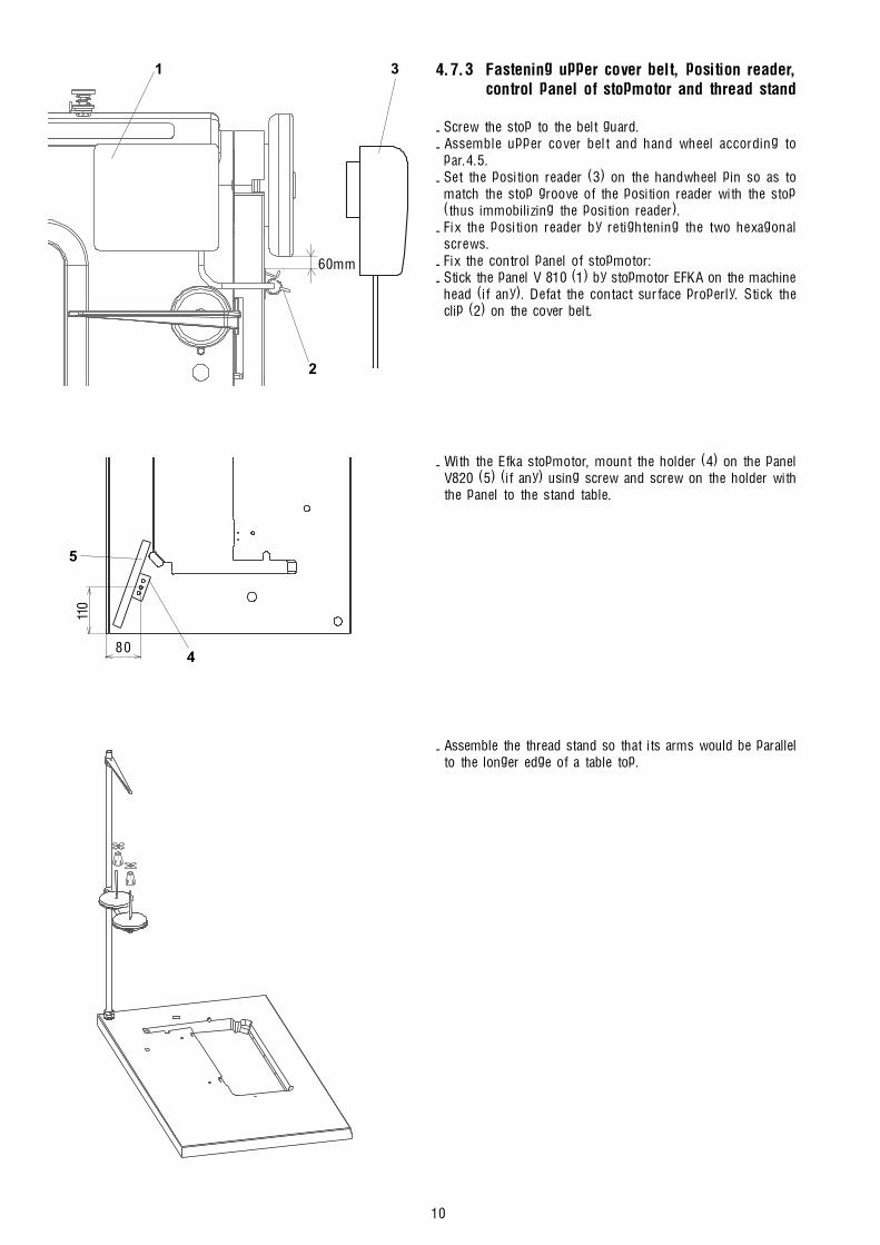
10
4.7.3 Fastening upper cover belt, position reader,control panel of stopmotor and thread stand
- Screw the stop to the belt guard.- Assemble upper cover belt and hand wheel according to
par.4.5.- Set the position reader (3) on the handwheel pin so as to
match the stop groove of the position reader with the stop(thus immobilizing the position reader).
- Fix the position reader by retightening the two hexagonalscrews.
- Fix the control panel of stopmotor:- Stick the panel V 810 (1) by stopmotor EFKA on the machine
head (if any). Defat the contact surface properly. Stick theclip (2) on the cover belt.
- With the Efka stopmotor, mount the holder (4) on the panelV820 (5) (if any) using screw and screw on the holder withthe panel to the stand table.
- Assemble the thread stand so that its arms would be parallelto the longer edge of a table top.
1
2
60mm
3
804
5
110
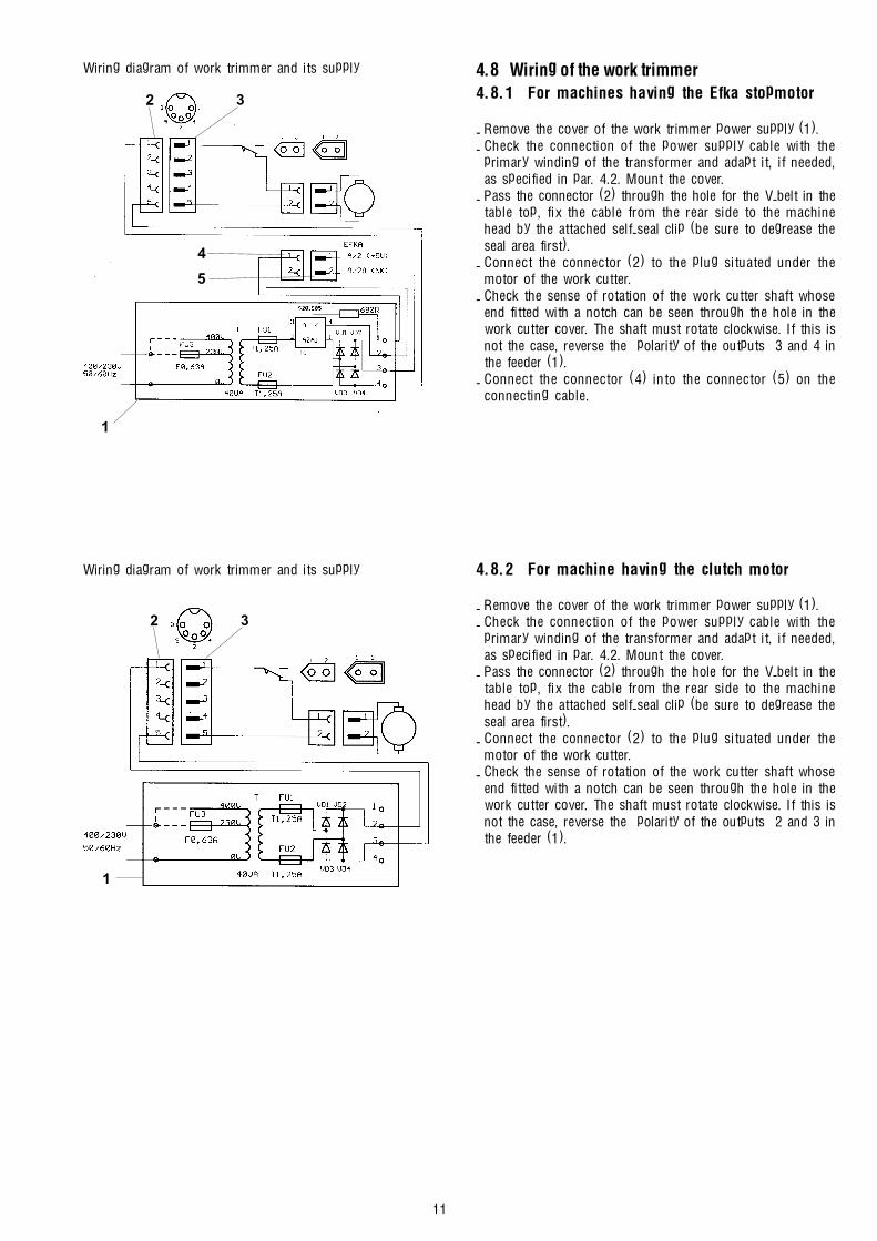
11
Wiring diagram of work trimmer and its supply 4.8 Wiring of the work trimmer4.8.1 For machines having the Efka stopmotor
- Remove the cover of the work trimmer power supply (1).- Check the connection of the power supply cable with the
primary winding of the transformer and adapt it, if needed,as specified in par. 4.2. Mount the cover.
- Pass the connector (2) through the hole for the V-belt in thetable top, fix the cable from the rear side to the machinehead by the attached self-seal clip (be sure to degrease theseal area first).
- Connect the connector (2) to the plug situated under themotor of the work cutter.
- Check the sense of rotation of the work cutter shaft whoseend fitted with a notch can be seen through the hole in thework cutter cover. The shaft must rotate clockwise. If this isnot the case, reverse the polarity of the outputs 3 and 4 inthe feeder (1).
- Connect the connector (4) into the connector (5) on theconnecting cable.
4.8.2 For machine having the clutch motor
- Remove the cover of the work trimmer power supply (1).- Check the connection of the power supply cable with the
primary winding of the transformer and adapt it, if needed,as specified in par. 4.2. Mount the cover.
- Pass the connector (2) through the hole for the V-belt in thetable top, fix the cable from the rear side to the machinehead by the attached self-seal clip (be sure to degrease theseal area first).
- Connect the connector (2) to the plug situated under themotor of the work cutter.
- Check the sense of rotation of the work cutter shaft whoseend fitted with a notch can be seen through the hole in thework cutter cover. The shaft must rotate clockwise. If this isnot the case, reverse the polarity of the outputs 2 and 3 inthe feeder (1).
Wiring diagram of work trimmer and its supply
32
1
32
1
5
4

12
5. Basic setting of stopmotor and position reader5.1 GenerallyThe procedure of setting parameters of the stopmotor S359 600045 XXX - EFKA DC 1600/DA82GA on the level of the operator isdescribed in the first part of the Instruction manual - par. 7.2.1.2 (V810); par. 7.2.2.2 (V820).A correct function of the sewing machine with drive is attained when changing some parameters of the drive, which are inacces-sible for the attendance of the machine. Hereinafter there is a description of the possible procesures of changing all parameters.
Procedure of changing parameters of the drive Efka S359 600045 810 - DC 1600/DA82GA; S359 600052 XX - VD 552/6F82FAand S359 600056 XX - VD 554/6F82FA (panel V 810)- depress the pushbutton P on panel and switch on thereafter the main switch- on the display there will appear C 0000, the 1st digit flashes- using pushbutton + - set the 1st digit on the value 3- depress the pushbutton >>, the 2nd digit flashes- in the same way set the remaining digits in the way to get displayed on the display C 3112 (the number of the code for the
possibility of changing all parameters of the drive)- depress the pushbutton E, on the display will appear F 200 (parameter number 200)- using pushbuttons >>, +, - set the required parameter number and depress the button E- using pushbuttons +, - set the required parameter value- depress the pushbutton E (a parameter number following in the sequence will appear) or P (the same parameter number will
appear)- carry out the termination of changes in depressing the pushbutton P (return to the respective sewing mode)You will find a detailed information in the original directins for use of the drive.Note: To get the change of parameters permanently stored, it is necessary, after having changed the parameter, to depress the
pedal in forward direction.
Procedure of changing parameters of the drive Efka S359 600045 820 - DC 1600/DA82GA; S359 600052 XX - VD 552/6F82FAand S359 600056 XX - VD 554/6F82FA (panel V 820)- depress the pushbutton P on panel and switch on thereafter the main switch- on the display there will appear C 0000, the 1st digit flashes- using pushbuton 0 ÷ 9 set C 3112 on the display (code number for possible changing of all drive parameters)- depress the pushbutton E, on the display will appear F 200 (parameter number 200)- using pushbutton 0 ÷ 9, set the required parameter number and depress the pushbutton E- using pushbutton +, - , set the required parameter value- depress the pushbutton E (there will appear further parameter number in the given sequence) or P (return to the given sewing
mode)- the termination of changes is to be done in depressing the pushbutton P (return to the sewing mode)A detailed information is in the original directions for use of the drive.Note.: To get the change of parameters permanently stored, it is necessary, after having changed the parameter, to depress the
pedal in forward direction.
5.2 Stopmotor setting S359 600045 XXX - EFKA DC 1600/DA 82 GA 33125.2.1 Setting position reader- set parameter 170, Sr1 is shown on the display (reference position)- depress pushbutton >>, PoS O appears on the display and changing symbol of rotation- turn the hand wheel until symbol of rotation disappears- turn the hand wheel to angular value 105° of hand wheel ( thread tip is approx. in the level of throat plate)- depress pushbutton E, changeover to parameter 171
- set parameter 171, Sr2 is shown on the display (all positions)- depress pushbutton >>- 1 XXX is shown on the display (value of first position of needle)- turn the hand wheel until value XXX begins changing- turn the hand wheel to the angular value of first position (135° on the hand wheel respective 30 on the panel)- depress pushbutton E- 2 XXX is shown on the display (value of upper position of take-up lever)- turn the hand wheel until value XXX begins changing- turn the hand wheel to the angular value of upper position (65° on the hand wheel respective 450 on the panel)- depress pushbutton P 2x (return to the sewing mode)- step shortly treadle down forwards (entry to the memory)

13
5.2.2 Changes of setting parameters of stopmotor setting considering original producer setting
Parameter ParameterNo value
111 - Max. revolutions (according to a type of machine)116 180 Trimming revolutions170 - Reference position171 30 First position of needle183 500 Switching off delay of the trimming device after having ended the sewing operation192 340 Delay angle of tensioner switch on202 120 Delay of start run after switch off the signal foot225 3 Type of the machine
5.3 Setting stopmotor S359 600052 XX-EFKA VD 552/6F82FA and S359 600056 XX-EFKA VD 554/6F82FA5.3.1 Setting position reader
Positions are set by means of discs with cut outs directly in position reader.
Setting bottom position:- Disassemble the cover of position reader- Disconnect head power supply cable from drive- Switch on the power supply switch- Step treadle shortly down forwards (machine stops in first position of needle)- Switch off the power supply switch- Turn the beginning of cut out 1 of coinciding discs so that machine would stop at the value 135° of the hand wheel- Carry out check by repeating procedure
Setting upper position of thread lever:- Step treadle down backwards (machine stops in upper position of needle)- Switch off the power supply switch- Turn the beginning of cut out 2 of separate disc so that machine would stop at the value 65° of the hand wheel- Carry out check by repeating procedure
5.3.2 Changes in parameters of stopmotor setting considering original producer setting
Parameter ParameterNo value
111 Max. revolutions (according to a type of machine)116 180 Trimming revolutions136 ON Stitch by thread trimmer (back)183 500 Switching off delay of the trimming device after having ended the sewing operation192 86 Delay angle of tensioner switch on202 120 Delay of start run after switch off the signal foot
6. Examination of sewing
Caution! Risk of injury!Before threading a thread switch the main switch off and wait until the motor stops.
- Check the sense of turning the hand wheel � according to the arrow situated on it.- Thread a thread.- Choose sewing material.- Switch the desirable function on the control panel of stopmotor. Examination should be carried out with selection of fancy bar.- First sew slowly then speed up the sewing.- If the stitch does not meet requirements, follow the first part of instructions manual or service book.
2 A1 A
12
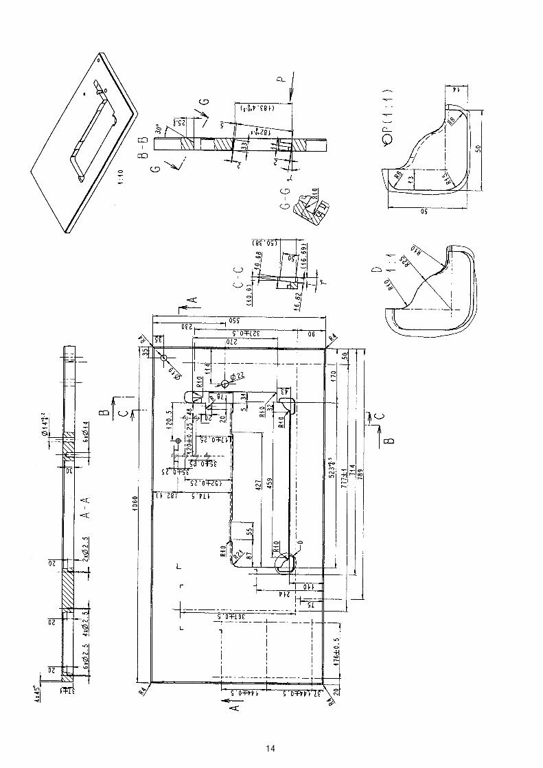
14

CONTENTS:
1. General safety instructions .............................................................................................................................................................. 1
2. Introduction .......................................................................................................................................................................... 1
3. Head of the sewing machine .............................................................................................................................................. 23. 1 Hook and hook post ................................................................................................................................................................ 2
.. 3.1.1 Description3.1.2 Height setting of the hook3.1.3 Setting the distance of the hook from the needle3.1.4 Angular setting of the hook (timing)3.1.5 Protection of the needle and of the hook point3.1.6 Setting of the bobbin case opener3.1.7 Setting the regulation of the hook lubrication3.1.8 Replacement of the hook3.1.9 Setting the gear3.1.10 Dismantling of the hook post
3.2 Needle and thread mechanism ............................................................................................................................................... 53.2.1 Description3.2.2 To check the handwheel angular adjustment3.2.3 Height setting of the needle bar3.2.4 Side setting of the needle bar holder3.2.5 Setting the needle (the needle bar holder) in the direction of sewing
3.3 Throat plate and its post ........................................................................................................................................................ 73.3.1 Description3.3.2 Mounting and removing the throat plate and its insert3.3.3 Side setting of the throat plate post
3.4 Thread tensioners and limiter ............................................................................................................................................... 83.4.1 Description3.4.2 Setting the tension of main and auxiliary tensioners3.4.3 Setting the tensioning mechanisms of the main tensioners3.4.4 Setting the adapting spring3.4.5 Setting the thread limiter3.4.6 Setting the additional thread limiter
3.5 Feeding mechanism of the needle feed and of the lower feed wheel ........................................................................ 103.5.1 Description3.5.2 Stitch length mechanism
3.5.2.1 Setting the upper eccentric3.5.2.2 Setting the prop3.5.2.3 a Forward and rearward stitch length distribution (rough)3.5.2.3 b Forward and rearward stitch length distribution (fine)3.5.2.4 Setting of the control knob (including the stitch length limitation)
3.5.3 Lower feed wheel3.5.3.1 Feeding clutches
3.5.3.1.1 Description3.5.3.1.2 Setting the lever of the second step of feeding(angle, position)3.5.3.1.3 Setting of the lower eccentric3.5.3.1.4 Setting the engagement and disengagement of the clutches
3.5.3.2 Wheel feeder and its post3.5.3.2.1 Height setting of the feeder and tensioning of the chain3.5.3.2.2 Replacement of the feeder
3.5.4 Setting the top roller (pressing force, height)3.6 Feeding mechanism of the top roller ................................................................................................................................15
3.6.1 Description3.6.2 Side setting of the indented lower pulley3.6.3 Side setting of the indented upper pulley3.6.4 Setting the tensioning roller3.6.5 Replacement of the indented belt3.6.6 Top roller
3.6.6.1 Selection of the top roller diameter3.6.6.2 Forward, rearward and side setting3.6.6.3 Setting the gear clearance and in the mounting of the top roller3.6.6.4 Replacement of the top roller

3.7 Setting the presser foot lift .................................................................................................................................................. 193.8 Bobbin winder ....................................................................................................................................................................... 20
3.8.1 Description3.8.2 Setting the bobbin winder stop3.8.3 Setting the friction gear
3.9 Safety clutch .......................................................................................................................................................................... 213.9.1 Description3.9.2 Setting the disengaging moment
3.10 Indented belt transmission ................................................................................................................................................. 213.10.1 Setting the tensioning roller of the indented belt3.10.2 Replacing the indented belt
3.11 V-belt, motor - head .............................................................................................................................................................. 223.11.1 Tensioning3.11.2 Replacing the V-Belt
3.12 Driving toothed belt ............................................................................................................................................................... 223.12.1 To exchange the driving toothed belt
3.13 Lubrication .............................................................................................................................................................................. 233.13.1 Description3.13.2 Refilling oil3.13.3 Multiple oil use
4. Thread trimming ................................................................................................................................................................................. 244.1 Description of the trimming mechanism4.2 Setting the pickup roller4.3 Setting the cam4.4 Setting the fork4.5 Setting the moving knife4.6 Setting the height of the fixed knife and of the retaining spring of the lower thread4.7 Setting the fixed knife4.8 Setting the retaining spring of the hook thread4.9 Setting switching of the electromagnets
5. Material trimming ............................................................................................................................................................................ 275.1 Setting of the eccentrics (basic) for the knives �A� and �C�5.2 Setting of the eccentrics for the knife �B�5.3 Setting of the stop screw5.4 Setting of the knife position in the direction of sewing5.5 Setting of the knife side position (against the cutting edge of the throat plate insert)
5.5.1 Setting of the lateral knife position to the sides5.5.2 Setting of the knife angle with regard to the throat plate insert (crossing)
5.6 Setting of the microswitch of trimming device motor switching-on5.7 Sharpening of knives
5.7.1 Hand sharpening (stoning) of the knives5.7.2 Machine sharpening of the knives
6. Lifting the top roller by electromagnet ....................................................................................................................................... 306.1 Description6.2 Setting the electromagnet pin6.3 Setting the electromagnet current6.4 Assembly of the top roller lifting electromagnet
7. Backtacking using electromagnet .................................................................................................................................................. 317.1 Description7.2 Electromagnet height setting7.3 Setting the position of push-buttons7.4 Change of the function of push-buttons
8. Connecting the electric elements on the machine head ......................................................................................................... 32
9. Drive, control panel, position sensor ......................................................................................................................................... 32
10. Maintenance (table of operations) ............................................................................................................................................... 33
11. Setting the machine according to the sewing category ............................................................................................................ 3311.1 Introduction11.2 Table of setting the machine according to the sewing category
1
1. General safety instructions
The non-observance of the following safety instructions can cause bodily injuries or damages to the machine.
1. The machine must only be commissioned in full knowledge of the instruction book and operated by persons with appropriatetraining.
2. Before putting into service also read the safety rules and instructions of the motor supplier.
3. The machine must be used only for the purpose intended. Use of the machine without the safety devices is not permitted.Observe all the relevant safety regulations.
4. When gauge parts are exchanged (e.g. needle, top roller, needle plate, feed dog and bobbin) when treading, when theworkplace is left, and during service work, the machine must be disconnected from the mains by switching off the masterswitch or disconnecting the mains plug.
5. Daily servicing work must be carried out only by appropriately trained persons.
6. Repairs, conversion and special maintenance work must only be carried out by technicians or persons with appropriatetraining.
7. For service or repair work on pneumatic systems the machine must be disconnected from the compressed air supply system.Exceptions to this are only adjustments and function checks made by appropriately trained technicians.
8. Work on the electrical equipment must be carried out only by electricians or appropriately trained persons.
9. Work on parts and systems under electric current is not permitted, except as specified in regulations DIN VDE 0105.
10. Conversions or changes to the machine must be authorized by us and made only in adherence to all safety regulations.
11. For repairs, only replacement parts approved by us must be used.
12. Commissioning of the sewing head is prohibited until such time as the entire sewing unit is found to comply with ECdirectives.
It is absolutely necessary to respect the safety instructions marked by these signs.Danger of bodily injuries !Please note also the general safety instructions.
IMPORTANT WARNING
In spite of all safety measures made on the machines, inappropriate actions of the operator may lead to dangerous situations. Inindustrial sewing machines, attention should be paid to the following still remaining possible sources of injury:
1. Moving sewing needle- risk of injury when sewing with raised pressure foot or top roller, because the finger guard is then positioned too high,- risk of injury when inadvertently threading down of the motor threadle.
2. Moving thread take-up lever- risk of injury when inadvertently or intentionally inserting the finger(s) between the thread take-up lever and its guard.
3. Moving pressure member- risk of injury when holding sewn work in immediate vicinity of the pressure member and beginning to insert under the
pressure member a considerably thicker sewn work portion,- risk of injury when sinking the pressure member.
4. Moving and also uncovered non-moving trimming knive- danger of accident when holding and guiding the sewn parts when sewing- danger of accident when handling the sewn parts even with the switched off trimming mechanism, without having
switched off the main switch5. When switched off, the clutch motor slows down by inertia but would be reactivated by an accidental treading down of the
motor treadle. To avoid such risk, it is advised to hold the handwheel by hand and slightly to depress the motor treadle.
2. Introduction
This service book contains instruction for regulating the mechanisms of the sewing machine head.The instructions for use and for putting the machine into operation and for the control of the stopmotor are not included in thisservice book, but they are supplied as separate publications.This service book is universal for all subclasses of the machine - it contains setting procedures for all elements which may beplaced on the machine of the given class. When the supplied subclass of this machine does not include some element, then it ispossible to leave out the respective parts of the instructions. The optional equipments of the machine and the respectiveconfigurations of the subclasses of the machine are given in the operating instructions.This sewing machine disposes of a large extent of its use. The machine should be set with respect to the parameters of the sewnmaterial, the sewing thread etc. The setting for the individual categories is given in the chapter 11.2.For setting the machine, simple setting aids are used which are included in the accessory of the machine. Besides these aids,universal measuring devices are used, such as slide calliper, feeler gauges and dynamometer for measuring the thread tension.

2
3. Head of the sewing machine
3.1 Hook and the hook post
3.1.1 DescriptionThe hook (1) is mounted on the shaft (2) and is driven by the gear (3)from the shaft (4).The shaft of the hook (2) is mounted on the top in a sliding bearingand, on the bottom, in a needle bearing.The hook is provided with a lever (6) which is tilted when removing thebobbin (7). The protecting sheet (8) protects against the collision ofthe needle with the hook point. The bobbin case opener (9) is driven bythe eccentric (10) on the shaft (2).The lubricating tube (11), on which a lubricating wick is fastened in thetube (12), feeds oil for lubricating the sliding bearing (5) of the eccentric(10) and the hook path.The screws (13) serve for taking up the clearance of the gear. Thescrews (14) fasten the post to the bedplate.The lubricating felt (15) is connected by the wick (16) with the lubricatingsystem and serves for lubricating the gear (3).
3.1.2 Height setting of the hookThe designated distance �A� should be 5.3 mm.
Caution! Danger of injury!Switch off the main switch ! Before starting the settingoperation, wait until the motor stops!
- Loosen both screws (2).- By turning the screws (3 and 4), set the required distance�A�. For
setting up use the setting gauge (7) as per the repectivefigure. After having set it, tighten carefully the screws.
- By axial shifting of the gear wheel (5), set the axial clearance insuch a way that this clearance is the least possible, but sufficient forturning easily the hook.
- Tighten carefully the screws (2). Caution ! One of these screws mustbear on the flat of the shaft 6).
3.1.3 Setting the distance of the hook fromthe needle
The hook point (1) is set up to the maximum distance of 0.1 mm fromthe bottom of the needle recess (2). For the sewing categories 1 and 2,the needle size 100 is set, for the sewing category 3, the needle size140 is set.
Caution! Danger of injury!Switch off the main switch ! Before starting the settingoperation, wait until the motor stops!
- Shift the plate (3).- Loosen only one screw (4).- Loosen the screws (5) and tighten them only slightly.- Shift the hook post (6) at the determined distance between the needle
and the hook point.- Tighten carefully the screw (4) (be sure not to damage the threads!)- Tighten duly the screws (5).- Check up the setting using a narrow strip of thin paper and proceed
to the eventual correction of setting.
5
1
2
34
8
9
12
13
14
15
16
34
2
6
1
max. 0,12
67
10
115
6
45
5
3
4
A6
7

3
3.1.4 Angular setting of the hook (timing)The hook is to be angularly set in such a way that the hook point (1) isopposite the needle at the moment, when the needle shifts by 2.5 mmfrom its bottom dead center. This corresponds to the 2O5° on the scaleof the handwheel (3).
Caution! Danger of injury!Switch off the main switch! Before starting the settingoperation, wait until the motor stops!
- Remove the throat plate.- Turn the handwheel (3) to the 2O5° and fix it with the screw (4)
which is component part ot the accessory of the machine (tightenit carefully).
- Loosen the screws (5).- Turn the hook into the required position.- Set up the distance of about 0,5 mm between the gear wheel (6) and
the pin (7).- Tighten to the maximum the screws (5).
3.1.5 Protection of the needle and of the hook pointThe protecting sheet (1) is to be set up in such a way that the clearancebetween the protecting sheet and the needle (2) is the least possible.
Caution ! Danger of injury!Switch off the main switch! Before starting the settingoperation, wait until the motor stops!
- Remove the throat plate.- In deforming the protective sheet (1) set the required play between
the sheet and the needle (2). After having introduced a suitablescrewdriver between the protective sheet and the hook body (3) weshall reduce the play by levering, in applying the pressure on theprotective sheet in the sense of the arrow (4), we shall increase theplay.
- Check up the protecting effect in pushing against the needle in thesense of the arrow (5). The hook point must not catch the needle. Ifso, set up the protecting effect, correct eventually the setting of thedistance of the hook point from the needle according to the paragraph3.1.3.
3.1.6 Setting of the bobbin case openerThe bobbin case opener (1) is to be set in such a way that, at themoment when the opener is in its dead centre, there would be a clearance�A� between the opener (1) and the projection (2), whereas the finger(3) bears on the projection (4), �A� = 0.7 mm for the sewing category1 and 2, �A� = 0.3 mm for the sewing category 3.
Caution ! Danger of injury!Switch off the main switch! Before starting the settingoperation, wait until the motor stops!
- Remove the sheet guard of the hook post.- On the handwheel (5), set the angle of 295° (the hook is in its dead
centre).- Loosen the screw (6).- Turn the eccentric (7) in such a way that the required clearance
between the elements (1) and (2) is attained.- Set the height of the eccentric (7) in such a way that it is in its
highest position in retaining the minimum clearance between theslide (8) and the fork (9).
- Tighten duly the screw (6).
12
3
4
205o
5 7
6 ~ 0,5
1
A
2
3
4
6
7 8 69
1
2
4
5
3
5
295o

4
3.1.7 Setting the regulation of the hook lubricationBy turning the lubricating tube (1) in the sense of the arrow (2), thesize of the contacting surface between the wick (3) and the felt insert(4) is regulated. In this way, the speed of the capillary lift of oil into thefelt insert (5) is influenced, from which oil is wiped on the surface (6)and is driven by centrifugal force into the hook path (7).Setting of full lubrication- Turn the screw (8) into the position (9).Setting of limited lubrication- Turn the screw (8) into the position (10).After having ended the regulation, set the height of the lubricating tube(1) at 0.4 mm from the eccentric (11).
3.1.8 Replacement of the hook
Caution! Danger of injury!Switch off the main switch ! Before starting the settingoperation, weit until the motor stops!
- Remove the throat plate and the trimming knife.- Unscrew the screws (1) and remove the gib (2).- After having suitably turned a bit the hook, remove the bobbin case
(3).- Unscrew thorougly the screw (4).- Remove the body of the hook (5) upwards.- When mounting, the procedure is inverse.
3.1.9 Setting the gearThe mutual angular orientation of the gear wheel (1) relative to the gearwheel (2) should ensure the accessibility of the screw (5) at the momentwhen the hook point comes to lie opposite the needle (4). The wheel(2) is to be set with its gear rim symmetrically to the centre of the gearwheel (1). The clearance between the gear wheels is to be the leastpossible.
Caution ! Danger of injury!Switch off the main switch! Before starting the settingoperation, wait until the motor stops!
- Set the angle of 2O5° on the handwheel (6) and lock it with thescrew (7).
- On the removed post of the hook (8), according to the pa-ragraph3.1.10, the hook point (3) is to be turned a bit according to theillustration.
- Turn the gear wheel (2) into the suitable position and insert the postof the hook into the machine according to the respective arrows.Check up, whether the screw (5) is accessible and, if not, repeat theprocedure.
- Set the the distance of the hook from the needle according to theparagraph 3.1.3.
- Set the precise angular displacement of the hook according to theparagraph 3.1.4.
- Loosen the screw (10) and tighten them slightly.- Set the clearence in the gear in turning the screws (9). Check up,
whether the gear has a clearance during the whole revolution of thehook. Turn the handwheel step by step by 15° and, with each step,grasp the hook and try, if there is an angular dead travel. Tightencarefully the screws (9).
- Tighten duly the screws (10) and try anew the clearance of the gear.
1
2
1
34
57
8
10
9
15 o
1
5
2
4
3
98
10
10
~0,5
1
2
3
4
5
7
6
205o
6
110,
4

5
3.1.10 Dismantling of the hook postWhen dismantling the post (1), the supplies of lubricating oil are to bedisconnected first, the fastening screws unscrewed and, thereafter, thepost is removed.
Caution ! Danger of injury!Switch off the main switch! Before starting the settingoperation, wait until the motor stops!
- Unscrew the screw (2).- Push the lubricating tube (3) downwards into the post.- Unscrew the screw (7) from the oil tank (8) and pull the tank out
from the machine.- Disconnect the hose with the wick (9) from the oil tank (8).- Loosen only one screw (5).- Unscrew the screws (6).- Shift the post in the sense of the arrows and remove it out from the
machine.- When mounting it, proceed inversely.
3.2 Needle and thread mechanism3.2.1 DescriptionThe take-up lever (1) is mounted in ball bearings, both at the spot of itssuspending on the connecting rod (2) and in the mounting on the loop(12). The take-up lever is of aluminum and is provided with a stuck-ineye for two threads. The connecting rod (2) is mounted on the eccentricpin (3). The needle rod holder (4) is mounted through the pivot (5) ina rotating way in the arm (6). In its top part, the holder is guided by theguide pin (7). The movement for the needle feed is given to it by theconnecting rod (8) driven by the feeding shaft (9). The connecting rod(8) is mounted by pin (13) with needle bar holder (4).The connecting rod (10) of the needle bar (11) on the loop (12) ismounted in a ball bearing and it is slidingly mounted on the needle barcarrier. The mechanism is lubricated by means of a central-wicklubricating system.
3.2.2 To check the handwheel angular adjustmentThe handwheel (5) must be situated in its precise position relative tothe needle and thread mechanism. This position is given by a pin (2),which locks the connecting rod of the needle rod (1) through a hole inthe arm (3). In this position, the indicator (6) of the handwheel mustshow �O�. The position is fixed by the handwheel screw (4) contactinga small flat surface provided on the upper shaft.The correct adjustment of the angular position has been car-ried out atthe producer�s.
Caution ! Danger of injury!Switch off the main switch! Before starting the settingoperation, wait until the motor stops!
3.2.3 Height setting of the needle barAt the moment, when the hook point passes around the needle, theupper edge of the needle eye must be about 1 mm below the hookpoint. In an opposite case, it is necessary to set the height of the needlebar as follows:
Caution ! Danger of injury!Switch off the main switch! Before starting the settingoperation, wait until the motor stops!
- Remove the front guard.- Loosen the screw (1) of the needle bar carrier- Set the correct height of the needle bar and tighten anew the screw
(1).
Caution !An incorrect setting of the needle bar height may causethe striking of the hook point against the needle.
0o
2
1
12
3
45 6
7
8
9
13
1011
1
2
3 45
6
1
1
1
5
6
6
32
7
8
9

6
3.2.4 Side setting of the needle bar holderThe correct position of this holder is in such case, when the needle baris lined up with the presser-foot bar. The needle bar holder can be setas follows:
Caution! Danger of injury!Switch off the main switch! Before starting the settingoperation, wait until the motor stops!
- Loosen the screw (1) of the pin (2).- Loosen the screw (3) of the guide pin (4).- In shifting the pin (2) set the needle bar holder on the measure �A�
= 8 mm (distance between the front face of the arm and the front faceof the safety bolt (5) of the needle bar holder) /at the same time thepin (4) shifts/.
- The guide pin (4) is to be set in such a way that the needle bar holdermoves easily.
- Tighten the screws (1 and 3).
3.2.5 Setting the needle (the needle bar holder)in the direction of sewing
When shifting out the needle from the throat plate insert, at the moment,when the needle eye is at the level of the top surface of the throat plateinsert (3), the distance between the needle and the wall of the throatplate insert must be �A� = 0.2 mm.
Caution ! Danger of injury!Switch off the main switch! Before starting the settingoperation, wait until the motor stops!
- Set the maximum allowed stitch length.- Set the handwheel (1) to the angle of 244° and lock it with the screw
(2).- Loosen the screw (4) of the lever (5).- By turning the needle bar holder (6) on the pin (7) set the required
distance �A� = 0,2 mm.- Tighten up the screw (4) and check up the setting.
Caution!A faulty setting may cause bending or breaking of needlesagainst the throat plate insert.
2
5
3
A
4
5
6
7
1
2
244o
A 1
34

7
3.3 Throat plate and its post
3.3.1 DescriptionThe throat plate (1) is equal for all categories of sewing. In the throatplate there is fixed by means of two screw (3) the exchangeable throatplate insert (2). Each category of sewing has its own insert of the throatplate which differ one from another by the length and width of thepiercinghole.
3.3.2 Mounting and removing the throat plate andits insert
When mounting the throat plate (1), the finger of the hook (2) must fitinto the recess (3) of the throat plate. When demouting or replacing thethroat plate insert (4), both screws (5) are to be unscrewed and theinsert romoved.
Caution! Danger of injury!Switch off the main switch! Before starting the settingoperation, wait until the motor stops!
- Place the insert (4) and screw in the screws (5).- Turn slightly the finger (2) in the sense towards the throat plate (1).- Place the throat plate (1) and screw in the screws (6).
3.3.3 Side setting of the throat plate postThe post of the throat plate (1) is to be side set in such a way that theaxis of the hole in the insert of the throat plate (2) is at the distance �A�= 0.1 mm to the right from the axis of the needle (3).
Caution! Danger of injury!Switch off the main switch! Before starting the settingoperation, wait until the motor stops!
- Loosen the screws (4 and 5) (from the rear side of the post as well).- Shift the post (1) in the sense required for attaining the distance
�A� = 0.1 mm.- Tighten the screws (4 and 5) and check up for the correct setting.
2
A
3
4
1
5
613 24
5
6
5
3
1
2

8
3.4 Thread tensioners and limiter3.4.1 DescriptionThe main tensioners (1) serves for creating the tension of the threadwhen tightening the stitch. The auxiliary tensioner (2) reduces the riskof pulling out of the thread after the thread trimming when removingthe sewn material, when the thread is passed through this material andwhen the main tensioner is relieved. The main tensioner is relieved bythe mechanism controlled by the shaft of the presser bar lifting (3)holding the lever (4) with a pulley. The motion is then transmitted bythe lever (5) and the tie rod (6) on the thread tensioner plate (7) whosedisplacement (motion) relieves the thread tensioner springs (8). Inmachines provided with a thread trimming device, the main tensioners(1) are relieved as well upon the switching on of the electromagnet(10) whose electromagnetic field will attract the thread tensioner plate(7). The mechanism of the adapting spring (12) maintains the upperthread in its tensioned state when passing through the hook and whenentering the needle into the sewn material. The thread limiter (13)limits the length of the thread fed by the take-up lever when movingfrom the upper to the bottom dead centre to get a controlled passing ofthe thread through the hook. The auxiliary guide (14) maintains theupper thread in front of the needle in a tensioned condition and helpsagainst pulling the thread from the needle after thread trimming.
3.4.2 Setting the tension of the main and auxiliarytensioners
The tension of the main thread tensioners is regulated by means of thenuts (1). The force of tensioning the thread is measured by thedynamometer (2) as it is shown on the illustration. The size of thisforce differs according to the category, and its orientation value isindicated in the par. 11.2.The tension of the auxiliary tensioner is regulated using the nut (3). Itshould be the least possible, but sufficient for unthreading the threadfrom the sewn material when removing the sewn material from thepressing element without leaving the tensioner.
3.4.3 Setting the tensioning mechanismsof the main tensioners
In the rest position of the tensioners, when pushing the plate of thetensioners on the spot �A� 3.4.1, this plate must have the socalled deadtravel of about 0,5 mm. At this lifting, the tension discs of the tensionersmust not be relieved. This can be attained by a suitable shaping of therelieving disc of the tensioners-this has been set up in the manufacturingfactory. In the maximum opened position of the tensioners, the plate ofthe tensioners, when pushing it at the spot �A� 3.4.1, must still havethe minimum lifting. This can be attained when axially shifting the lever(3) with the roller (5) on the shaft (4).The disengagement of the main tensioners must be coordinated withthe top roller lift. To achieve this, turn the lever (3) with the roller (5) onthe shaft (4). The movement of the roller (5) on the slanting surface (6)of the lever (7) disengages the tensioners. In this way, also a lag of theupper thread tension disengagement after the top roller lift can beobtained.
Caution ! Danger of injury!Switch off the main switch! Before starting the settingoperation, wait until the motor stops!
- Remove the rear cover with the top roller lift magnet.- Loosen the screws (1) and (2) of the lever (3).- In the rest state of the machine (with not relieved tensioner discs) set
the lever (3) in turning it slightly on the shaft (4) to a position inwhich the roller (5) of the lever (3) is in contact with the slantingsurface (6) of the lever (7) and is about 0.1 mm distant from the flatsurface (8) of the lever.
- At the maximum lift of the top roller, the roller (5) moves on the flatsurface (9) of the lever (7); in this condition, there must be a minimalplay at the tensioner plate lift (when pushing qat the spot �A� (3.4.1),the plate must still have a minimum lifting - between the roller (5)and the surface (9) there is a minimum clearance). Retighten thescrews (1) and (2), check the play, and correct it in case of need.
3
4
5610
A
7
2
1
13
12
14
8
2
3
1
4 1 73 2 5
8
0,1
69
9
3.4.4 Setting the adapting springThe mechanism of the adapting spring is in the machine arm set by thepin (1) and fixed by the screw (2). The axial adjustment shall ensurethat the surfaces of the parts (3) and (4) are aligned (the threadedthread must in no place break on edges). The initial position of theadapting spring (5) shall ensure that �B� = 1 to 1.5 mm (see theFigure).
Caution! Danger of injury!Switch off the main switch! Before starting the settingoperation, wait until the motor stops!
- Loosen the screw (2) and take the mechanism out of the machinearm.
- Turning the body (6) relative to the pin (1), set the required initialposition of the adapting spring /the screw (7) has been set at theproducer´s so as to permit the turning movement of the body (6) thescrew must not be fully tightened/.
- During the installation of the mechanism into the machine arm takecare of the axial adjustment of the mechanism.
- Retighten the screw (2) and check the adjustment.- Loosen the nut (8) of the mechanism, insert a screwdriver into the
notch of the screw (9) and set the required value of the adaptingspring. By turning the screw clockwise you increase the springforce, and vice versa.
- Retighten the nut (8) and check the function of the adapting spring.
3.4.5 Setting the thread limiterThe thread limiter is to be set in such a way that, when sewing andpassing the thread through the most distant point of the hook, thespring (2) shifts by about 1/4 to 1/2 length of its total length. Thismeans that the thicker will be the sewn material and the longer will bethe stitch length, the more will be the limiter shifted in the sense of thearrow and inversely. Under standard sewing conditions, the threadlimiter is set in its tested positions depending on the sewing categoryin accordance with the chapter 11.
Caution! Danger of injury!Switch off the main switch! Before starting the settingoperation, wait until the motor stops!
- Tighten the screw (3).- Set the thread limiter (1) so as to ensure a minimum motion of the
adapting spring (2) when the thread passes around the bottom ofthe hook.
- Tighten the screw (3).
3.4.6 Setting the additional thread limiterFor improving the uniformity of stitch interlocking with some (e.g. toothin) materials, the machine is provided with an additional thread limiterwhich is to be set as follows:
Caution! Danger of injury!Switch off the main switch! Before starting the settingoperation, wait until the motor stops!
- Set the stitch length to the required value.- Sew an approximately 5 cm long seam along the edge of sewn work,
switch off the machine, and tilt away the hook cover.- Rotate the handwheel until the thread taken up by the hook will be
stretched across its bottom, i.e., across the full diameter of the hook.- Adjust the position of the additional limiter (1) so as to obtain an
almost complete stretching of the thread (2) at that moment, as shownin the drawing.
- Sew next stitch and check the adjustment.
8
3
4
2
3
1
5
A
4
9
3
6
7
1
28
9
2
1
10
CD
AB
1
4
0o
6 7 819
3
2
5
2
90o
6
10 1
4
3
7
154
5
13
12
14
11 10
6
8
7
2
1
9
3 3.5 Feeding mechanism of the needle feedand of the lower feed wheel
3.5.1 DescriptionThe feeding mechanism is formed by the leverage (1) which is drivenfrom the main shaft through the eccentric with connection rod (2). Thefeeding motion is transmitted by the shaft (3) on the clutch of thebottom feed (7).The engaging and the disengaging function of the clutch (7) is controlledfrom the lower shaft (8) through the eccentric with the connecting rod(9) and through the wedge coupling (10).The feeding movement is transmitted by the shaft (11) through thechain transmission (12) onto the wheel feeder (13).The stitch length is set by the knob (14) through the leverage (15) tothe feeding mechanism (1).3.5.2 Stitch length mechanism3.5.2.1 Setting the upper eccentricThe eccentric (1) must be set in its angular position in such a way thatthe horizontal component of the needle motion is in a phase delay fromthe vertical component of this movement. This refers to the angle of90° on the handwheel (2), when the setting stick (3) is engaged intothe eccentric (1) and leans from above against the feeding shaft (4).
Caution! Danger of injury!Switch off the main switch! Before starting the settingoperation, wait until the motor stops!
- Set the angle 90° on the handwheel (2) and fix it with the screw (5)which is component part of the accessory of the machine (tighten itwith care).
- Loosen the gripping joints of the levers (6) and (7).- Turn the feeding shaft (4) in such a way, so that the recesses (flats)
point towards the bedplate (owing to the unambi-guous setting ofthe eccentric by means of the setting bar).
- Insert the setting bar (3) into the hole in the eccentric (1) and propit from above against the feeding shaft (4).
- Shift axially the eccentric (1) on the shaft into its extreme positionsand place it in the middle.
- Tighten the screws of the eccentric (1) to the maximum (one screwfirst and, after having turned slightly the hand-wheel, the secondscrew as well).
- Turn the feeding shaft (4) back into the position for setting theleverage in such a way, so that the levers (10) of the mechanism passin the spots of the recesses.
- Tighten the gripping joints of the levers (6) and (7).- Test the sufficient clearance in the recesses of the feeding shaft (4)
and, using the levers (10) with the maximum stitch length forwardand rearward � push against the reverse stitching lever.
- Correct eventually the position of the feeding shaft.
3.5.2.2 Setting the propIn this machine with a wheel feed, the prop (1) is mounted in the pits(A and C) as per the drawing.3.5.2.3aForward and rearward stitch length
distribution (rough)The cam (1) is to be set at the respective angle in such a way that thestirrup (6) is oriented in such a position, so that the connecting rods (7and 8) are in a line with a thoroughly screwed in knob (9) and withturning the handwheel at 0°. This setting can be done only after havingset the top eccentric according to the paragraph 3.5.2.1.
Caution! Danger of injury!Switch off the main switch! Before starting the settingoperation, wait until the motor stops!
- Set the zero stitch /screw in the knob (9) to the bottom of the cam(1)/.
- Set the angle 0° on the handwheel and lock it with the screw (4).- Turn the screw (3) in the respective sense in such a way that the
connecting rods (7 and 8) are in a line and tighten the screw (2).

11
3.5.2.3bForward and rearward stitch lengthdistribution (fine)
When setting the maximum length of the stitch, the forward and therearward stitch length must be equal with the maximum error of ± 5 %.This setting can be done only after having set the needle bar holder inthe direction of sewing (par. 3.2.6) and the wheel feed (par. 3.5.3.1.2).
Caution! Danger of injury!switch off the main switch! Before starting the settingoperation, wait until the motor stops!
- Set the maximum stitch length .- Place a suitable material under the presser foot and mark therein the
forward and the rearward stitch length.- With an unequal length of the stitch, proceed to the correction
of setting by turning the screws (2 and 3). When tightening thescrew (3), the forward length of the stitch is shortened and inversely.When tightening the screw (2), the forward stitch length is lenghtened.
- Each time first loosen one screw and then retighten theother one.
3.5.2.4 Setting the control knob(including the stitch length limitation)
The control knob (1) is to be set up in such a way that, when turning itin counterclockwise sense up to the stop, the maximum stitch lengthvalid for the given sewing category is attained (cat. 1: 3 mm, cat. 2 and3 : 5 mm). The scale of the control knob is to be oriented in such aposition, so that the scale end corresponds to the maximum stitchlength, excepting the first sewing category, where the stitch length ofthe indicator is 3 mm.
Caution! Danger of injurySwitch off the main switch! Before starting the settingoperation, wait until the motor stops!
- Screw in the screw of the control knob in such a way, that thespherical surface of the screw (3) bears on the seat of the cam (4).
- Loosen the screw (5) and turn the control knob in the clockwisedirection, until the pin (6) of the knob (1) bears on the pin (7).Tighten firmly the screws (5).
- Turn the knob in the counterclockwise direction up to the stop, whenthe pin (6) of the knob (1) bears on the pin (7).
- In a sewing test check up the length of the stitch, if this correspondsto the maximum stitch length valid for the given sewing category.
- If the stitch is longer, loosen then the screws (5) and turn the knobin the clockwise direction and inversely. Tighten firmly the screws(5).
- Insert a screwdriver into the hole (8) of the scale (2) and adjust thescale in such a way that the maximum length on the scale is againstthe marking of the stitch length on the machine arm.
- For the sewing category 1, set the control knob (1) on the stitchlength of 3 mm and check it by a sewing test.
- Loosen the screws (5) and turn the control knob (1) in thecounterclockwise direction, until the pin (6) of the knob (1) bearson the pin (7). Tighten firmly the screws (5).
- Put a screwdriver into the hole (8) of the scale (2) and adjust thescale in such a way that the value of the stitch length on the scaleagainst the marking on the arm is 3 mm.
3
2
125
34
6
7
5
12 8

12
3.5.3 Lower feed wheel3.5.3.1 Feeding clutches3.5.3.1.1 DescriptionThe feeding clutch is formed by the clutch cover (1) driven from theconnecting bar (2), by the clutch star (4) driven from the connectingrod (3) and by the carrier plate (5) firmly connected with the shaft (6).Of the clutch give the connecting rods (2 and 3) an opposite directionswinging movement. The clutch is coupled by means of the wedge (7)on the connecting rod (8) through the eccentric (9) which is placed onthe lower shaft (10).In the position, when the wedge is disengaged, the star (4) isshifted out from the frictioning engagement with the lining of the carrierplate (5) by means of the spring washer (11). The plate (5) lining isthen pushed by means of a flat profiled spring (12) against the cover ofthe clutch (1).In the position, when the wedge is disengaged, the star (4) ispushed against the plate (5) lining and, at the same time, the frictionconnection with the cover of the clutch (1) is disconnected. Within ashort instant, when engaging and disengaging with the carrier plate(5), there are in a friction engagement both the cover (1) and also thestar (4), namely in the dead centre of the connecting rods (2 and 3).The setting of the change-over of clutches is done by tightening or byloosening the nut (13).
3.5.3.1.2 Setting the lever of the second step offeeding (angle, position)
The lever of the second step (1) must be set in such a waythat, in the bottom dead centre of the needle, the axis of thespider part (2) lies in the screw axis (3). The pin screw (4) can bemounted into the position - 4.1 - corresponds to the maximum stitchlength of 5 mm.
Caution! Danger of injury!Switch off the main switch! Before starting the settingoperation, wait until the motor stops!
Lever (1) displacement.- Loosen the screw (6).- Set the maximum stitch length.- Set the angle 180° on the handwheel.- Unscrew the screw (5) and put the needle shank in its hole.- Turn the lever (1) until the needle drops into the clutch disk (2).- Side set the lever (1) to the measure �A�= 0.5 to 1 mm.- Tighten the screw (6).- Screw in the screw (5) and seal it with the Loctite cement.
3
9
1
13
7
4 12
511
6
10
8
2
25
1 4
A
3 2
5
8
6
41
4.1

13
3.5.3.1.3 Setting of the lower eccentricThe rotation of the eccentric (3) must be delayed in phase by 1/4revolution against the rotation of the eccentric of the stitch length. Thiscorresponds to the angle of 244° on the handwheel (1), when thesetting pin (4) is put into the eccentric (3) which is in contact with theindented belt (5).
Caution! Danger of injury!Switch off the main switch! Before starting the settingoperation, wait until the motor stops!
- Set 244° on the handwheel (1) and lock it with the screw (2), whichis included in the accessory of the machine (tighten it carefully).
- Put the setting stick (4) into the hole in the eccentric (3) and prop itfrom below against the indented belt (5).
- Set eccentric (3) axially.- Tighten it the utmost the screws of the eccentric (6).- By means of the handwheel, turn the eccentric (3) into the marked
position and check in this position the clearance �A� = 0.05, proceedeventually to its correction by a new side setting of the eccentric.
3.5.3.1.4 Setting the engagement anddisengagement of the clutches
The nut (7) is to be side set in such a way that the shifting of theclutches is done at the moment when the clutch disks (3) do not move,which means, when they are at the dead center of their oscillatingmovement. This corresponds to the angle 90° on the handwheel.
Caution! Danger of injury!Switch off the main switch! Before starting the settingoperation, wait until the motor stops!
- Loosen the screws of the indented pulley of feeding and shift it to theleft.
- Set the maximum stitch length.- Set the angle 90° on the handwheel (1) and lock it with the screw
(2). which is included in the accessory of the machine (tighten itcarefully).
- Loosen three screws (6) in the nut (7) and unscrew it by 2 mm to theleft.
- Tighten slowly the nut (7), until it strikes against the axial bearing(9). (At this moment, the tightening moment increases in jumps)and tighten the screws (6).
- Set the the handwheel on 85° and push the backtacking lever, thefeeder is to turn against the movement of the needle. Set then thehandwheel on 95°, the feeder is to be turned in the sense of theneedle movement. If not being so, correct the side setting of the nut(7). When the clutches shift too soon, turn a bit the nut (7) to theright and inversely.
- Tighten the screws (6).- Return the indented pulley in its original place according to the
paragraph 3.6.2.
244o
2
1
3
6
45
A
1
2
90o
67
9 3
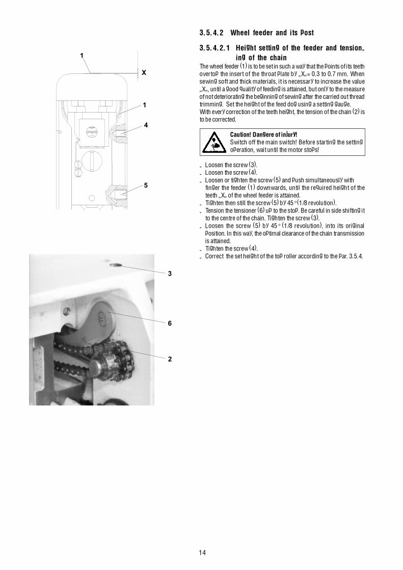
14
3.5.4.2 Wheel feeder and its post
3.5.4.2.1 Height setting of the feeder and tension-ing of the chain
The wheel feeder (1) is to be set in such a way that the points of its teethovertop the insert of the throat plate by �X�= 0.3 to 0.7 mm. Whensewing soft and thick materials, it is necessary to increase the value�X�, until a good quality of feeding is attained, but only to the measureof not deteriorating the beginning of sewing after the carried out threadtrimming. Set the height of the feed dog using a setting gauge.With every correction of the teeth height, the tension of the chain (2) isto be corrected.
Caution! Dangere of injury!Switch off the main switch! Before starting the settingoperation, wait until the motor stops!
- Loosen the screw (3).- Loosen the screw (4).- Loosen or tighten the screw (5) and push simultaneously with
finger the feeder (1) downwards, until the required height of theteeth �X� of the wheel feeder is attained.
- Tighten then still the screw (5) by 45° (1/8 revolution).- Tension the tensioner (6) up to the stop. Be careful in side shifting it
to the centre of the chain. Tighten the screw (3).- Loosen the screw (5) by 45° (1/8 revolution), into its original
position. In this way, the optimal clearance of the chain transmissionis attained.
- Tighten the screw (4).- Correct the set height of the top roller according to the par. 3.5.4.
X
4
5
1
1
3
6
2

15
3.5.3.2.2 Replacement of the feederFor the replacement of the wheel feeder (change of the wheel feederaccording to the machine setting - see par. 11.2 - setting of the machine- feeder - pitch of the teeth).
Caution! Danger of injury!Switch off the main switch! Before starting the settingoperation, wait until the motor stops!
- Unscrew the screws (1) and remove the throat plate (2).- Unscrew the guard (7).- In pulling upwards (securing by a spring), pull out the feeder (3)
with the guide (4).- Replace the feeder (3).- Insert the feeder with the guide into the groove of the holder (5).- Mount the throat plate (2) and tighten up the screws (1).- Check up, if the spring (6) pushes the guide (4) with the feeder (3)
against the wheel (8).- In the opposite case, loosen the screws (9), tense up the spring (6)
in such a way,so that the guide (4) with the feeder (3) is pushedagainst the wheel (8) and tighten the screws (9).
- Mount the guard (7) and tighten the screws.
3.5.4 Setting the top roller (pressing force, height)When lowering the top roller (1), set the clearance �A� between thefeeder (5) and the top roller to the maximum of 0.2 mm. Set the pressingforce of the top roller (1) so as to avoid the slippage of the sewn materialwhen feeding it.Method of setting the height of the top roller:- Lower by hand the presser bar (3) with the top roller (1) above the
wheel feeder (5).- Loosen the screw (4) and set the required value �A�=0.2 mm.- Tighten the screw (4).Setting the force of the top roller (1).- In screwing in the screw (2),the force of the top roller is increased and
inversely.
3.6 Feeding mechanism of the top roller
3.6.1 DescriptionThe starting movement for the drive of the top roller feeder is thebottom feeding shaft. From this shaft, the movement is transmitted bythe indented belt (1) onto the top feeding shaft (2). A component partof the transmission by indented belt is the pulley (3), the tensioningroller (4), the roller (5) and the pulley (6). Starting from the shaft (2),the movement is further transmitted through the wheels (7 and 8)ontothe articulated shaft (9). From this articulated shaft, the movementis transmitted by a cone transmission, situated in the holder (10), ontothe feeder wheel (11). The shaft of the wheel (8) is mounted in thescrew (12) on bearings. The articulated shaft (9) contains two joints(15) and a telescopic part (16). Both these elements secure the liftingand the tilting of the top roller.
2 17
6
9
34
58
2
1
4
3
5A
62
5
1
4
3
159
16
15
1011
8131214
7

16
3.6.2 Side setting of the indented lower pulleyThe pulley must be set up in such a way that the belt passes through thecentre of the passing hole in the bedplate. The setting operation is to bedone as follows:
Caution! Danger of injury!Switch off the main switch! Before starting the settingoperation, wait until the motor stops!
- Loosen the screws (1) of the pulley (2).- Loosen the screw (3) of the tensioning roller (4)- Set the pulley (2) in such a way that the belt (5) passes through the
centre of the passing hole in the bedplate (6).- Tighten the screws (1).- Set the tensioning roller (4) axially in such a way that the belt (5) is
set at the middle of the tensioning roller (4).- Set the tensioning roller (see par. 3.6.4).- Tighten up the screw (3) of the tensioning roller (4).
3.6.3 Side setting of the indented upper pulleyThe pulley is to be set in such a way that the indented belt is not crossedand the pulleys are in line. The setting thereof is to be done as follows:
Caution! Danger of injury!Switch off the main switch! Before starting the settingoperation, wait until the motor stops!
- Loosen the screws (1) of the pulley (2).- Set the pulley (2) in such a way that the distance of 5 mm is
attained in accordance with the illustration.- Tighten the screws (1).
3.6.4 Setting the tensioning rollerThe tensioning roller of the indented belt of the top feeding ismounted in a rotary way on the bedplate. The belt must be ten-sionedas needed in such a way that there is ensured the correct function of thetransmission. Insufficient tension can cause skipping of the teeth, onthe contrary, excessive tensioning enormously loads the mounting ofthe top shaft. The setting thereof is to be done as follows:
Caution! Danger of injury!Switch off the main switch! Before starting the settingoperation, wait until the motor stops!
- Loosen the screw (1) securing the lever of the tensioning roller (2).- Tension the belt as needed (theoretically, in applying the force of 10
N in the middle of the belt with the deflection of 4 mm).- Tighten the screw (1).
4
3
5
1
26
2
1
1
2
5

17
3.6.5 Replacement the indented beltBefore replacing the indented belt, the bottom feeding shaft is to beremoved. The procedure is as follows:
Caution! Danger of injury!Switch off the main switch! Before starting the settingoperation, wait until the motor stops!
- Loosen the screw (1) of the tensioning roller (2) and loosen it.- Loosen the screws (3) of the pulley (4) and shift it to the left in such
a way that the screws (5 and 6) of the feeding clutch (7) are accessible.- Loosen the screws (5 and 6).- Loosen the screws (8) of the axial ring (9).- Loosen the screws (10) of the chain wheel (11).- Push the shaft (12) to the left in such a way that it is out of the pulley
(4).- Remove the pulley (4).- Remove the front guard.- Loosen and unscrew the screw (14) of the holder of the wheel (15)
and remove it from the holder (21).- Loosen the screws (16 and 17) of the holder (18).- Remove the holder (18) together with the holder (15) and articulated
shaft (13) from the machine.- Loosen the screws (19) of the pulley (20).- Loosen the screw (24) of the ring (25).- Hold the pulley (20) and pull out the feeding shaft (22) from the arm
in such a way that it is possible to remove the indented belt (23)from the arm of the machine.
- Replace the belt with a new one and proceed to the assembly (invertedprocedure of dismantling).
- Proceed to the setting operation according to the par. 3.6.2, 3.6.3and 3.6.4.
1110 12 438 91 2
5 6 7
2115
14
24
22
2513
17
18
16
23
20
19
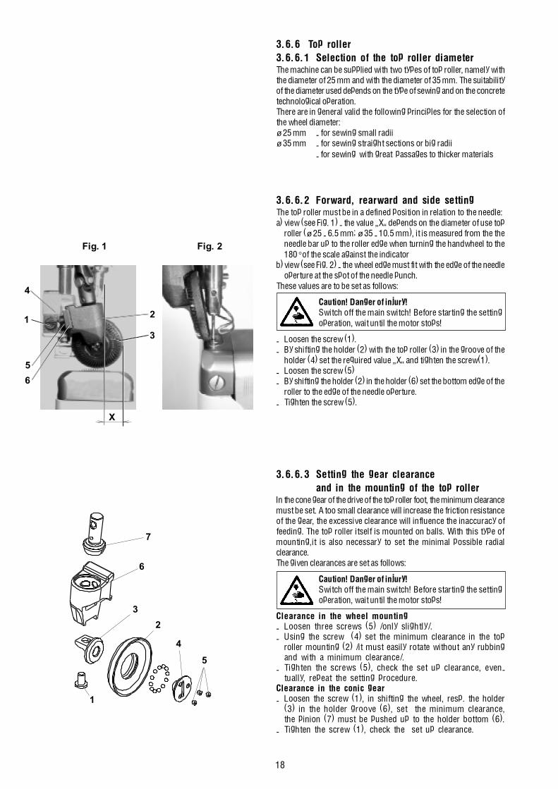
18
3.6.6 Top roller3.6.6.1 Selection of the top roller diameterThe machine can be supplied with two types of top roller, namely withthe diameter of 25 mm and with the diameter of 35 mm. The suitabilityof the diameter used depends on the type of sewing and on the concretetechnological operation.There are in general valid the following principles for the selection ofthe wheel diameter:ø 25 mm - for sewing small radiiø 35 mm - for sewing straight sections or big radii
- for sewing with great passages to thicker materials
3.6.6.2 Forward, rearward and side settingThe top roller must be in a defined position in relation to the needle:a) view (see Fig. 1) - the value �X� depends on the diameter of use top
roller (ø 25 - 6.5 mm; ø 35 - 10.5 mm), it is measured from the theneedle bar up to the roller edge when turning the handwheel to the180° of the scale against the indicator
b)view (see Fig. 2) - the wheel edge must fit with the edge of the needleoperture at the spot of the needle punch.
These values are to be set as follows:
Caution! Danger of injury!Switch off the main switch! Before starting the settingoperation, wait until the motor stops!
- Loosen the screw (1).- By shifting the holder (2) with the top roller (3) in the groove of the
holder (4) set the required value �X� and tighten the screw(1).- Loosen the screw (5)- By shifting the holder (2) in the holder (6) set the bottom edge of the
roller to the edge of the needle operture.- Tighten the screw (5).
3.6.6.3 Setting the gear clearanceand in the mounting of the top roller
In the cone gear of the drive of the top roller foot, the minimum clearancemust be set. A too small clearance will increase the friction resistanceof the gear, the excessive clearance will influence the inaccuracy offeeding. The top roller itself is mounted on balls. With this type ofmounting,it is also necessary to set the minimal possible radialclearance.The given clearances are set as follows:
Caution! Danger of injury!Switch off the main switch! Before starting the settingoperation, wait until the motor stops!
Clearance in the wheel mounting- Loosen three screws (5) /only slightly/.- Using the screw (4) set the minimum clearance in the top
roller mounting (2) /it must easily rotate without any rubbingand with a minimum clearance/.
- Tighten the screws (5), check the set up clearance, even-tually, repeat the setting procedure.
Clearance in the conic gear- Loosen the screw (1), in shifting the wheel, resp. the holder
(3) in the holder groove (6), set the minimum clearance,the pinion (7) must be pushed up to the holder bottom (6).
- Tighten the screw (1), check the set up clearance.
Fig. 1
X
3
2
6
5
1
4
Fig. 2
4
3
1
2
7
5
6
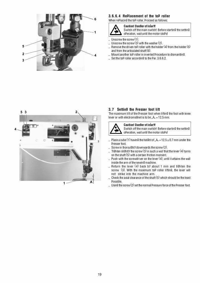
19
3.6.6.4 Replacement of the top rollerWhen replacing the top roller, proceed as follows:
Caution! Danger of injury!Switch off the main switch! Before starting the settingoperation, wait until the motor stops!
- Unscrew the screw (1).- Unscrew the screw (3) with the washer (2).- Remove the driven top roller with the holder (4) from the holder (5)
and from the articulated shaft (6).- Mount another top roller in inverted procedure to dismantling.- Set the top roller according to the par. 3.6.6.2.
3.7 Setting the presser foot liftThe maximum lift of the presser foot when lifting the foot with kneelever or with electromagnet is to be �A� = 12.5 mm.
Caution! Danger of injury!Switch off the main switch! Before starting the settingoperation, wait until the motor stops!
- Place a cube (1) having the height of �A� = 12.5 ± 0.7 mm under thepresser foot.
- Screw in thoroughly downwards the screw (2).- Tighten slightly the screw (3) in such a way that the lever (4) turns
on the shaft (5) with a certain friction moment.- Push with the screwdriver on the lever (4), until it attains the wall
inside the arm of the sewing machine.- Return the lever (4) back by about 1 mm and tighten the
screw (3). With the maximum top roller lifting, the lever willnot strike into the machine arm.
- Check the axial clearance of the shaft (5) which should be the leastpossible.
- Using the screw (2) set the normal pressure force of the presser foot.
4
5 3 2
1 A
6
3
1
42
5

20
3.8 Bobbin winder
3.8.1 DescriptionThe winder (bobbin winder) winds a reserve of the hook thread.It is driven by a spring-mounted friction gear, which stops after havingfilled the bobbin.An ideal winding is attained with a sufficient pretension of the threadobtained on the thread guide (4) and with 1 mm under the diameter ofthe bobbin. The shaft is mounted in a swinging way and the frictiongear is put into engagement by means of a pickup lever (1) and a cam.The winder is fixed on the machine arm by two screws (3). The threadis passed through according to the illustration, the thread is cut offafter having stopped the winding operation using the cutting device(5).
3.8.2 Setting the bobbin winder stopThe moment of interrupting the winding is determined by the mutualposition of the pickup lever (1) and the cam (5) on a common shaft.The cam is locked in its functional position by the screw (6). Themutual position is to be set on a not incorporated winder in such a waythat in the moment, when the pickup lever leaves the space of thebobbin, the pressing function of the cam on the winders shaft isinterrupted and it moves in the sense of the arrow. A fine setting is tobe done on an incorporated condition in the machine. Using the screw(2), the position of the friction part of the pickup lever (1) is adapted. Inopening the lever, the stopping function is accelerated. Its inversefunction delays it. A test is to be done after having inserted the bobbin,when passing the thread through the device and when winding at therunning of the machine.
3.8.3 Setting the friction gearThe friction gear is formed frontally by the disk (8) on the main topshaft of the machine and by the disk (7) with a rubber ring on the shaftof the winder.
Caution! Danger of injury!Switch off the main switch! Before starting the settingoperation, wait until the motor stops!
- Proceed to the setting operation with a removed rear guard.- The winder is in its stopped position.- Loosen two screws (9) in the disk (8) through the hole in the arm.- By shifting axially the disk in the sense A, B, set the disks of the
winder (7) at the distance of 0.5 mm from the rubber ring.- Tighten the screws (9) in the disk (8).- Put the winder in its working position and proceed to a winding test.- Mount the rear guard.
1
5
1
4
3
3
6
52
7
8
9
A B
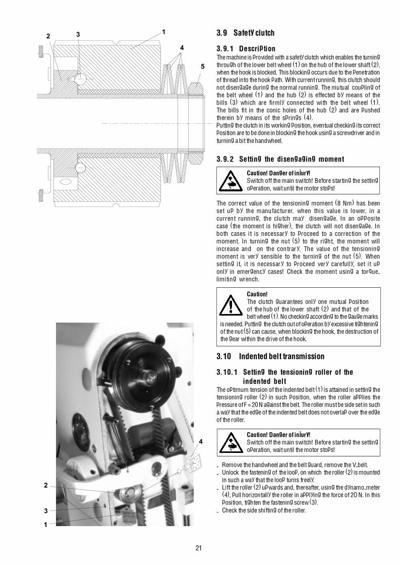
21
3.9 Safety clutch
3.9.1 DescriptionThe machine is provided with a safety clutch which enables the turningthrough of the lower belt wheel (1) on the hub of the lower shaft (2),when the hook is blocked. This blocking occurs due to the penetrationof thread into the hook path. With current running, this clutch shouldnot disengage during the normal running. The mutual coupling ofthe belt wheel (1) and the hub (2) is effected by means of thebills (3) which are firmly connected with the belt wheel (1).The bills fit in the conic holes of the hub (2) and are pushedtherein by means of the springs (4).Putting the clutch in its working position, eventual checking its correctposition are to be done in blocking the hook using a screwdriver and inturning a bit the handwheel.
3.9.2 Setting the disengaging moment
Caution! Danger of injury!Switch off the main switch! Before starting the settingoperation, wait until the motor stops!
The correct value of the tensioning moment (8 Nm) has beenset up by the manufacturer. when this value is lower, in acurrent running, the clutch may disengage. In an oppositecase (the moment is higher), the clutch will not disengage. Inboth cases it is necessary to proceed to a correction of themoment. In turning the nut (5) to the right, the moment willincrease and on the contrary. The value of the tensioningmoment is very sensible to the turning of the nut (5). Whensetting it, it is necessary to proceed very carefully, set it uponly in emergency cases! Check the moment using a torque-limiting wrench.
Caution!The clutch guarantees only one mutual positionof the hub of the lower shaft (2) and that of thebelt wheel (1). No checking according to the gauge marks
is needed. Putting the clutch out of operation by excessive tighteningof the nut (5) can cause, when blocking the hook, the destruction ofthe gear within the drive of the hook.
3.10 Indented belt transmission
3.10.1 Setting the tensioning roller of theindented belt
The optimum tension of the indented belt (1) is attained in setting thetensioning roller (2) in such position, when the roller applies thepressure of F = 20 N against the belt. The roller must be side set in sucha way that the edge of the indented belt does not overlap over the edgeof the roller.
Caution! Danger of injury!Switch off the main switch! Before starting the settingoperation, wait until the motor stops!
- Remove the handwheel and the belt guard, remove the V-belt.- Unlock the fastening of the loop, on which the roller (2) is mounted
in such a way that the loop turns freely.- Lift the roller (2) upwards and, thereafter, using the dynamo-meter
(4), pull horizontally the roller in applying the force of 2O N. In thisposition, tighten the fastening screw (3).
- Check the side shifting of the roller.
1
2
3
4
5
1
4
3 2
22
3.10.2 Replacing the indented beltTo observe: in machines with Mini-stop first remove the driving toothedbelt as instructed in par. 3.12.When replacing the indented belt, the mutual position of the pulleys (4and 5) should be maintained.
Caution! Danger of injury!Switch off the main switch! Before starting the settingoperation, wait until the motor stops!
- Remove the handwheel, the belt guard and the V-belt.- Remove the retaining ring (1) and remove the backtacking lever (2).- Mark with a pencil the instantaneous position of the indented pulleys
against the machine head in any position.- Remove the indented belt (3) from the bottom indented pulley
(4) first, and then remove the whole belt.- Apply a new indented belt on the top indented pulley (5) first.- Turn both indented pulleys in the formerly marked positions and
apply the indented belt on the indented pulley (4).- Tension the belt and mount the dismantled components in the inverse
order.
3.11 V-belt, motor - head3.11.1 Tensioning
Caution! Danger of injury!Switch off the main switch! Before starting the settingoperation, wait until the motor stops!
The belt is correctly tensioned, when the opposite sides of the beltapproach one to another by up to 20 mm in applying the force of 10 N.The belt is tensioned in turning respectively the motor in its holder.
3.11.2 Replacing the V-Belt
Caution! Danger of injury!Switch off the main switch! before starting the settingoperation, wait until the motor stops!
- Loosen the screw (1) of the positioner arrest (2) and tilt the arrest.- Unscrew the screws (3) of the handwheel.- Unscrew the screws (4) of the belt guard and tilt the guard.- Remove the belt guard of the motor and tilt the protections against
falling out the belt from the motor pulley.- Replace the belt.- Tension the belt (see par. 3.11.1).
3.12 Driving toothed belt
3.12.1 To exchange the driving toothed belt
Caution! Danger of injury!Switch off the main switch! before starting the settingoperation, wait until the motor stops!
- Remove the machine head from the stand (uncouple the motor cables,the machine head cable and screw off the wood screw and the screwfrom the hinges).
- Remove the belt guard (1).- Replace the belt (2).
3
51
4 3 2
10 N
10 N
l - 20mm
2 1 4
2
1

23
3.13 Lubrication
3.13.1 DescriptionFrom the oil tank (1) there issue three suction wicks. The wick (2)lubricates the pin of the thread mechanism, the wick (3) lubricates theneedle mechanism and the wick (4) lubricates the stitch lengthmechanism. The superfluous oil from the needle and thread mechanismsis sucked off by the wick (5) and lubricates the shifting wedge of thefeeding clutch.The hook has its own oil reservoir (6). The driving gear of the hook islubricated from oil tank (7).
3.13.2 Refilling oilFor lubricating the machine oil Esso SP-NK 10, DA 10 is used or otheroil with the same quality. When putting the machine into operation,each mechanism of the machine is to be lubricated with several dropsof oil. Oil is only refilled thereafter into the oil reservoirs using an oilcan into the holes in the oil level indicators.The oil tanks (1, 2, 3) of the central distribution is to be filled up to themark max.
3.13.3 Multiple oil useOil which runs into the oil cup is collected in the collector (1) and maybe reused for refilling the oil reservoirs in the machine - see par.3.13.2.The oil collector (1) with the collected oil is uscrewed and the top partof the oil can (2) which is added in the machine packing is screwed in.Oil is then refilled into the reservoirs on the machine head and everythingis put into the original condition.
3
5
1
2
6
4
1
2
1
1
2
7
3

24
4. Thread trimming4.1 Description of the trimming mechanismDuring the trimming cycle, the moving trimming knife (1), in anopportune moment, hooks up the sewing threads and pulls them in thesense of the arrow (A) against the fixed knife (2) until the threads aretrimmed. The spring (3) holds the hook thread after being trimmed off.The moving knife (1) is mounted on the shaft (4) which turns by meansof the lever (5) under the effect of the fork (6) fixed on the shaft (7)which is shifted by the electromagnet (8) from its starting position inthe sense of the arrow (B). When moving back in the sense of the arrow(C), the shaft (7) is shifted by the cam (9) through the pickup roller(10) into the starting position. The spring (11) maintains the mechanismin its starting position. The electromagnet (12), in an opportunemoment, loosens the main tensioner. At the end of the trimmingcycle, both electromagnets (8 and 12) are switched off.
4.2 Setting the pickup rollerThe holder of the pickup roller (1) is to be fixed in such a way that it ispositioned, in its starting position, between the shaft (2) and the shaft(3), the respective gap �A� = 0.2 to O.4 mm.
Caution! Danger of injury!Switch off the main switch! Before starting the settingoperation, wait until the motor stops!
- With the loosened screw (4), put the holder of the pickup roller (1)up to the stop against the bracket (5) and, at the same time, t h eshaft (2) up to the stop against the shaft (3).
- With the holder (1) held on the stop, shift the shaft (2) in such a waythat there appears the gap �A� = 0.2 to 0.4 mm, and tighten thescrew (4).
- Check the gap �A� in shifting the armature (6).
4.3 Setting the camThe position of the cam (1) against the shaft (2) is to be such, so thatwhen the adjusting pin is in contact with the shaft (4), the protractorscale of the handwheel (6) shows just the angle of 108°. If the pickuproller (5) is in its starting position of rest, the clerarance between theroller (5) and the cam (1) should be as small as possible but sufficientto prevent the cam from getting into accidental contact with the roller.
Caution! Danger of injury!Switch off the main switch! Before starting the settingoperation, wait until the motor stops!
- Set the angle of 108° on the handwheel (6) and lock it with the screw(7) which is included in the accessory of the machine (tighten withcare).
- Shift the pickup roller (5) in the sense of the arrow up to the stop.- Insert the adjusting pin (3), which is included in the accessory, into
the cam and turn the cam, until the pin (3) gets the contact with theshaft (4).
- Insert a gauge having the thickness of 0.1 mm between the cam (1)and the pickup roller (2) and shift the cam against the gauge up tothe stop. Tighten then the screw (8).
- Loosen the blocking of the handwheel, turn a bit the cam and tightenthe second fastening screw of the cam too.
12
2 3 1
4
B
C
11 10 865 97
A
2 A
1 3 64
5
6
7
108o
5
13824

25
4.4 Setting the forkIn the starting position of rest of the trimming mechanism, when theholder (1) is in contact with the bracket (2), the axis of the fork (3)must intersect the axis of the shaft (4).
Caution! Danger of injury!Switch off the main switch! Before starting the settingoperation, wait until the motor stops!
- Shift the shaft (5), until the holder (1) strikes the bracket (2).- Loosen the screw (6).- Shift the fork (3) in such a way that its axis intersects the axis of the
shaft (4).- Tighten the screw (6).
4.5 Setting the moving knifeThe moving trimming knife (1) is to be placed in its starting positionat rest with its end at the distance of the measure �A�= 0.1 to 0.5 mmfrom the edge of the fixed trimming knife (2).The height setting is to be such that its top surface is 1.8 mm below thetop surface of the throat plate.
Caution! Danger of injury!Switch off the main switch! Before starting the settingoperation, wait until the motor stops!
- Loosen the screws (4 and 5).- Turn the moving trimming knife (1) in the sense of the arrow and set
it in height. Tighten the screw (5).- Turn the moving trimming knife (1) into its starting position in such
a way that the measure�A� = 0.1 to 0.5 mm is attained. Tighten thescrew (4).
4.6 Setting the height of the fixed knife and of theretaining spring of the lower thread
The fixed knife (1) and the retaining spring (2) are fixed on the holder(3). This holder is fixed with the screw (4) on the post of the hook (5).In its height, the holder (3) is to be set in such a way, so that the topsurface of the fixed knife (1) is by 1.8 mm below the top surface of thethroat plate.
Caution! Danger of injury!Switch off the main switch! Before starting the settingoperation, wait until the motor stops!
- Loosen the screw (4).- In shifting the holder (3) in the hook post (5), set necessary position
of 1.8 mm.- Tighten up the screw (4), check the correct setting.
4.7 Setting the fixed knifeThe fixed trimming knife (1) is to be tensed up using the screw (2) insuch a way, so that it bears against the moving trimming knife in the 1/2 of its length. The knives need not to trim untensioned threads.
Caution! Danger of injury!Switch off the main switch. Before starting the settingoperation, wait until the motor stops!
- Set the angle of 300° on the handwheel (4).- Shift by hand the moving knife (3) into the marked position.- Loosen the screw (2)ba hand, in shifting the fixed knife (1) set its
position, tighten then the screws (2).- Check the bearing spot of the moving trimming knife (3) on the fixed
trimming knife (1) and give it a correction, if needed.
21
563
4
4
2
1
3 4 5
1,8
mm
321
1/2
1/2
4
300o
5
2
1
A
26
4.8 Setting the retaining spring of the hook threadThe retaining spring (1) holds the hook thread after having performedthe trimming. It is to be set in such a way that the force necessary forpulling out the thread from the retaining spring (1) is approximatelyequal to the force necessary for pulling out the thread from the hook.
Caution! Danger of injury!Switch off the main switch! Before starting the settingoperation, wait until the motor stops!
- Shape the retaining spring (1) in such a way that it fits close with allits surface (without wedge) onto the moving trim-ming knife (3).
- Shape the retaining spring in such a way that it fits close, with theslightly tightened screw (2), onto the moving trimming knife withoutany pressure.
- Tighten the screw (2), until the necessary force for pulling the threadfrom the retaining spring is attained. The pulling force is testedusing a screwdriver (4) according to the illustration.
Caution!The setting of the retaining spring (1) depends on thesetting of the hook thread tension and differs thenaccording to the respective sewing category.
The adjusting screw (2) should not be screwed in in such a waythat the retaining spring gets over the perimeter of the movingtrimming knife.
4.9 Setting the switching of electromagnetsThe electromagnets of the trimming device and loosening of thetensioner must work in accordance with the diagram. This is ensuredby setting the stopmotor (see the instructions for use of the stopmotor).
1- 1. position of the needle (135° on the handwheel);2- 2. position of the needle (64° on the handwheel)3- position of stopping the tensioner (10° ÷ 25° on the hand-wheel)4- movement of the pickup roller of the trimmer cam5- current of the trimming device electromagnet6- current of the tensioner loosening electromagnet
4
5
6
1 3 2
3
2 13
1
31
2
4

27
2
1
3
43
2
91011
23
4
1
5. Material trimming
5.1 Setting of the eccentrics (basic)for the knives �A� and �C�
For the knives �A� and �C�, the mutual orientation of the eccentrics (2,3) should be such, so that their counterweights are in alignment (thisrefers to the largest possible stroke of the knife = 2,4 mm).
Caution Danger of injury!Switch off the main switch! Before starting the settingoperation, wait until the motor stops!
- Remove the trimming device guard.- Loosen the screws (1).- Set the eccentrics (2, 3) in such a way, so that both screws (1, 4) are
oriented in the same way.- Tighten the screws (1).- Attach the trimming device guard.- Check the setting of the knife (see Instruction manual, par. 6.15).
5.2 Setting of the eccentrics for the knife �B�For the knife �B�, the counterweights of the eccentrics are to bemutually oriented by 120° (this corresponds to the knife stroke of 1.2mm).
Caution! Danger of injury!Switch off the main switch! Before starting the settingoperation, wait until the motor stops.
- Remove the trimming device guard.- Loosen the screws (1).- Set the eccentrics (2, 3) in such a way, so that only one screw (1, 4)
is oriented in the same way.- Tighten the screws (1).- Attach the trimming device guard.- Check the setting of the knife (see Instruction manual, par. 6.15).
5.3 Setting of the stop screwThe stop screw (10) is to be duly screwed in, but in such a way, so thatthere occurs no spontaneous trimming device switching off .
Caution! Danger of injury!Switch off the main switch: Before starting the settingoperation, wait until the motor stops!
- Remove the trimming device guard.- Screw in duly the screw (10) but in such a way, so that the trimming
device, when being switched on, could not be switched off whendepressing the holder (11) and so that, at the same time, thereoccurs no clearance between the holder (11) and the screw (10)when being switched on.
- Tighten the screw (9).- Attach the guard.- Check the setting of the knife (see Instruction manual, par. 6.15).
The trimming knife, in its bottom dead centre, must notstrike with its cutting edge in the throat plate insert. In itstop dead centre, it should not leave the throat plateinsert.
28
1
2
3
4
21
5.4 Setting of the knife position in the directionof sewing
The forcing off screw (4) for setting the position of the trimmingdevice body is to be so screwed in , so that the knife touches the rearedge of the gauge (2) supplied together with the machine.
Caution! Danger of injury!Switch off the main switch. Before starting the settingoperation wait until the motor stops!
- Remove the throat plate insert, see par. 3.3.2.- Put back the throat plate (1).- Slide in the gauge (2) into the hole for the throat plate insert and
push it up to its rear edge.- Engage with care the trimming device.- Using the screws (3,4), set the knife in such a way, so that it slightly
touches the gauge with its rear edge.- Disengage the trimming device.- Tighten up the screws (3).- Engage with care the trimming device and check its setting.- Attach the throat plate insert, see par. 3.3.2.- Check the knife setting, see Instruction manual, par. 6.15.
The cutting knife must not strike, in its bottom deadcentre, with its cutting edge in the throat plate insert. Inits top dead centre, the trimming knife must not leave thethroat plate insert.
5.5 Setting of the knife side position (againstthe cutting edge of the throat plate insert)
For a precise setting, a magnifying glass is to be used.
For correct function of the trimming device, for a long service life of theknife and of the insert, it is necessary that the knife and the cutting edgeof the insert are parallel and that there is no clearance between themand that the knife is not excessively pushed against the throat plateinsert.
5.5.1 Setting of the lateral knife position to the sides
Caution! Danger of injury!Switch off the main switch! Before starting the settingoperation, wait until the motor stops!
- When engaging the trimming device, check the parallelism of theknife and of the cutting edge of the throat plate insert. When needed,carry out the necessary setting according to the par. 5.5.2.
- Loosen the screw (1) and, thereafter, tighten it slightly.- Engage the trimming device.- Set the knife using the screw (2)with regard to the throat plate insert
in such a way, so that they touch slightly one another. (In looseningthe screw (2), the knife approaches the throat plate insert and intightening it, the knife moves away from the throat plate insert).
- Tighten up the screw (1).- Tighten up the screw (2) by about 1/4 revolution in such a way, so
that the thread clearance is taken up.- Disengage and engage with care the trimming device.- When the knife approaches slightly the edge of the throat plate
insert, go ahead further, when this runs with difficulty, or when theknife bends, repeat anew the previous proce-dure.
- Disengage the trimming device.- Switch on the machine.- Engage with care the trimming device.
Caution! Danger of accieent!With the trimming device engaged, do not put your fingersunder the trimming knife.
29
1
2
3
1
2
- When during the approach of the knife against the throat plateinsert edge there ocrrurs a marked increase of noise, tightenslightly the screw (2) in such a way, so that the knife, when beingengaged, approaches slightly in eliminating almost the noise and,at the same time, there occurs no clearance between the knife andthe throat plate insert.
With an unsuitable setting or when tighteninginsufficiently the screw (1), the knife, the throat platemay be damaged or the trimming device may functionincorrectly.
5.5.2 Setting of the knife angle with regard tothe throat plate insert (crossing)
For setting the parallelism (crossing) of the knife and the throat plateinsert cutting edge there serves the wedge (1).
Caution! Danger of injury!Switch off the main switch! Before starting the settingoperation, wait until the motor stops!
- Loosen slightly the screws (2) to loosen the trimming knife.- Loosen the screw (3).- Shift the wedge (1) upwards or downwards in such a way, so that
when tightening the screws (2), the knife is parallel to the cuttingedge of the throat plate insert. Exceptionally, for some specificmaterials, a slight crossing of the knife may be set, but this causesalso an increased wear of the knife and of the throat plate insert).
- Tighten the screw (3).- Proceed to the setting of the knife, see Instruction manual, par. 6.15.
When incorrectly setting the knife, the knife or the throatplate insert may be damaged or, eventually, a wrongfunction of the trimming device may occur.
5.6 Setting of the microswitch of trimming devicemotor switching-on
The microswitch of the trimming device motor switching-on is to beswitched on prior to its contact with the trimmed material of the maximumthickness of 5 mm, when the knife is in the bottom dead center of itsoscillating movement.
Caution! Danger of injury!Switch off the main switch! Before starting the settingoperation, wait until the motor stops!
- Remove the trimming device guard.- Loosen the screws (1).- Shift the microswitch (2) in such a way,. so that the trimming device
is engaged with the knife positioned 5 mm above the throat plateinsert in the bottom dead centre of the knife.
- Tighten the screws (1).- Attach the trimming device guard.
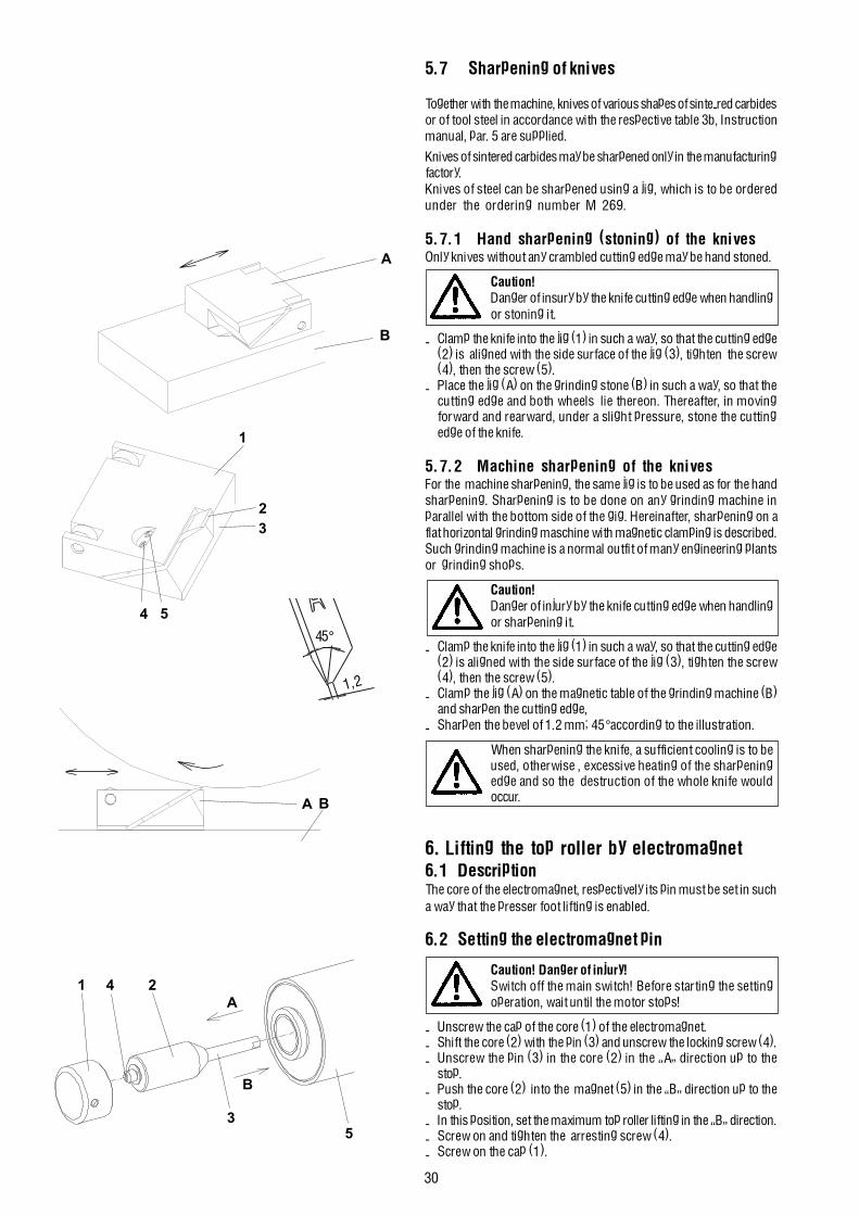
30
241
35
A
B
A
B
1
23
54
A B
45°
1,2
5.7 Sharpening of knives
Together with the machine, knives of various shapes of sinte-red carbidesor of tool steel in accordance with the respective table 3b, Instructionmanual, par. 5 are supplied.
Knives of sintered carbides may be sharpened only in the manufacturingfactory.Knives of steel can be sharpened using a jig, which is to be orderedunder the ordering number M 269.
5.7.1 Hand sharpening (stoning) of the knivesOnly knives without any crambled cutting edge may be hand stoned.
Caution!Danger of insury by the knife cutting edge when handlingor stoning it.
- Clamp the knife into the jig (1) in such a way, so that the cutting edge(2) is aligned with the side surface of the jig (3), tighten the screw(4), then the screw (5).
- Place the jig (A) on the grinding stone (B) in such a way, so that thecutting edge and both wheels lie thereon. Thereafter, in movingforward and rearward, under a slight pressure, stone the cuttingedge of the knife.
5.7.2 Machine sharpening of the knivesFor the machine sharpening, the same jig is to be used as for the handsharpening. Sharpening is to be done on any grinding machine inparallel with the bottom side of the gig. Hereinafter, sharpening on aflat horizontal grinding maschine with magnetic clamping is described.Such grinding machine is a normal outfit of many engineering plantsor grinding shops.
Caution!Danger of injury by the knife cutting edge when handlingor sharpening it.
- Clamp the knife into the jig (1) in such a way, so that the cutting edge(2) is aligned with the side surface of the jig (3), tighten the screw(4), then the screw (5).
- Clamp the jig (A) on the magnetic table of the grinding machine (B)and sharpen the cutting edge,
- Sharpen the bevel of 1.2 mm; 45°according to the illustration.
When sharpening the knife, a sufficient cooling is to beused, otherwise , excessive heating of the sharpeningedge and so the destruction of the whole knife wouldoccur.
6. Lifting the top roller by electromagnet6.1 DescriptionThe core of the electromagnet, respectively its pin must be set in sucha way that the presser foot lifting is enabled.
6.2 Setting the electromagnet pin
Caution! Danger of injury!Switch off the main switch! Before starting the settingoperation, wait until the motor stops!
- Unscrew the cap of the core (1) of the electromagnet.- Shift the core (2) with the pin (3) and unscrew the locking screw (4).- Unscrew the pin (3) in the core (2) in the �A� direction up to the
stop.- Push the core (2) into the magnet (5) in the �B� direction up to the
stop.- In this position, set the maximum top roller lifting in the �B� direction.- Screw on and tighten the arresting screw (4).- Screw on the cap (1).
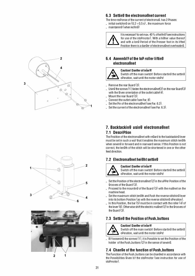
31
1
3
4
2
2 1
12
34
5
6
6.3 Setting the electromagnet currentThe time response of the current of electromag. has 2 phases:- initial switching on (0,2 ÷ 0,5 s) - the maximum force- maintaining (when keying)
It is necessary to set max. 40 % of keying (see instructionsfor use of the stopmotor). With a higher value thereofand with a long period of the presser foot in its liftedposition there is a danger of electromagnet overheating.
6.4 Aseembly of the top roller liftingelectromagnet
Caution! Danger of injury!Switch off the main switch! Before starting the settingoperation, wait until the motor stops!
- Remove the rear guard (3).- Using the screws (1),fasten the electromagnet(2) on the rear guard(3)
with the given orientation of the outlet cable(4).- Mount the rear guard (3).- Connect the outlet cable (see par. 8).- Set the pin of the electromaghet (see par. 6.2).- Set the current of the electromagnet (see par. 6.3).
7. Backtacking using electromagnet7.1 DescriptionThe position of the electromagnet with regard to the backtacking levermust be set in such a way that it enables the maximum stitch lengthwhen sewing in forward and in rearward sense. If this position is notcorrect, the length of the stitch will be shortened in one or the otherfeed direction.
7.2 Electromagnet height setting
Caution! Danger of injury!Switch off the main switch! Before starting the settingoperation, wait until the motor stops!
- Set the position of the electromagnet (2) in the upper position of thegrooves of the guard (3).
- Proceed to the mounting of the guard (3) with the magnet on themachine head.
- Set the maximum stitch length and push the reverse stitching leverinto its bottom position (as with the reverse stitching operation).
- In this position, the bar (5) must be in contact with the roller (4) ofthe lever (6). Otherwise shift the electric magnet (2) in the grooves ofthe guard (3).
7.3 Setting the position of push-buttons
Caution! Danger of injury!Switch off the main switch! Before starting the settingoperation, wait until the motor stops!
- By loosening the screws (1), it is possible to set the position of theholder of the push-buttons (2) in the sense of sewing.
7.4 Change of the function of push-buttonsThe Function of the push-buttons can be changed in accordance withthe possibilities given by the stopmotor (see instruction for use ofstopmotor).
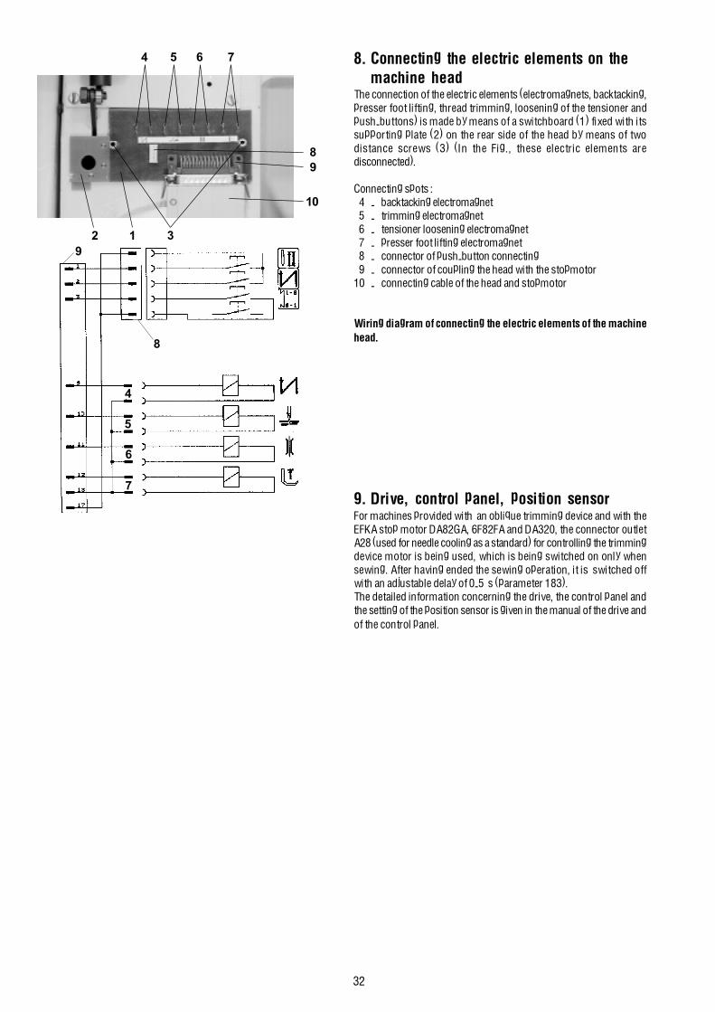
32
4 5 6 7
10
89
2 1 39
8
4
5
6
7
8. Connecting the electric elements on themachine head
The connection of the electric elements (electromagnets, backtacking,presser foot lifting, thread trimming, loosening of the tensioner andpush-buttons) is made by means of a switchboard (1) fixed with itssupporting plate (2) on the rear side of the head by means of twodistance screws (3) (In the Fig., these electric elements aredisconnected).
Connecting spots :4 - backtacking electromagnet5 - trimming electromagnet6 - tensioner loosening electromagnet7 - presser foot lifting electromagnet8 - connector of push-button connecting9 - connector of coupling the head with the stopmotor
10 - connecting cable of the head and stopmotor
Wiring diagram of connecting the electric elements of the machinehead.
9. Drive, control panel, position sensorFor machines provided with an oblique trimming device and with theEFKA stop motor DA82GA, 6F82FA and DA320, the connector outletA28 (used for needle cooling as a standard) for controlling the trimmingdevice motor is being used, which is being switched on only whensewing. After having ended the sewing operation, it is switched offwith an adjustable delay of 0-5 s (parameter 183).The detailed information concerning the drive, the control panel andthe setting of the position sensor is given in the manual of the drive andof the control panel.

33
10. Maintenance
Caution! Danger of injury!The maintenance operations should be performed only with the machine switched off and with the motor stopped!
In the following table there are given the operations which should be performed and the respective time intervals between the individual operations.
Operation Time interval
Removal of the throat plate and its cleaning out.Cleaning out of the wheel feeder, hook and theirsurrounding space. Removal of the residues of material and threads from the top roller. 1 day
Checking the oil level in oil reservoirs. 1 month
Checking the hook wear. Checking the function of the safety clutch against the hook overload. 6 months
Checking the V-belt and the indented belts. 1 year
11. Setting the machine according to the sewing category
11.1 IntroductionThe sewing machine enables sewing within the extent from the light to medium heavy-duty sewing. The setting of the machine must be adapted tothe sewing parameters including also replacement of some components, such as e.g. needle, the throat plate insert. For this reason, the setting ofthe machine is divided into 3 categories:1 ... light sewing2 ... medium sewing3 ... medium heavy-duty sewing
In the factory, where this machine has been manufactured, the machine has been set with respect to the standard parameters of the required sewingcategory which is designed by the number included in the commercial designation of the machine. If the user desires changing the given setting toanother sewing category, this operation should be performed by a specialized mechanician.
The standard parameters of sewing are described in the following paragraph. The actual parameters of sewing inside the given sewing category maybe different, which means that the machine operative must adapt respectively the setting of the machine, e.g. the tension of the upper thread.
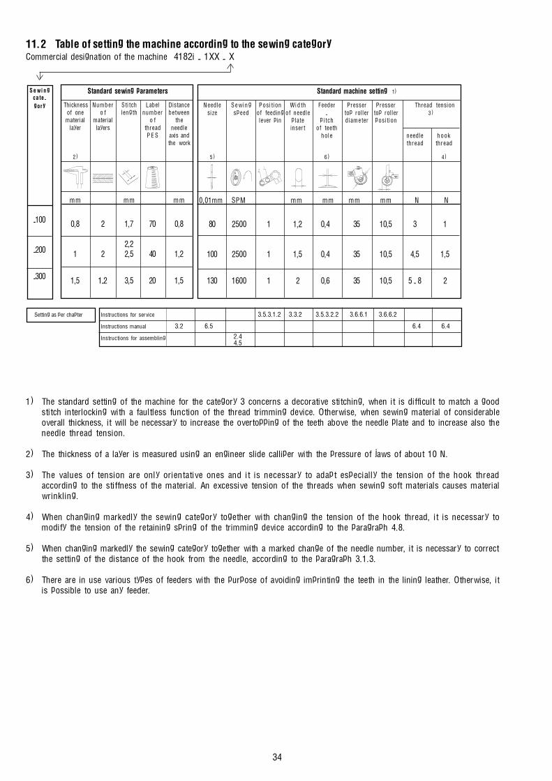
34
11.2 Table of setting the machine according to the sewing categoryCommercial designation of the machine 4182i - 1XX - X
1) The standard setting of the machine for the category 3 concerns a decorative stitching, when it is difficult to match a goodstitch interlocking with a faultless function of the thread trimming device. Otherwise, when sewing material of considerableoverall thickness, it will be necessary to increase the overtopping of the teeth above the needle plate and to increase also theneedle thread tension.
2) The thickness of a layer is measured using an engineer slide calliper with the pressure of jaws of about 10 N.
3) The values of tension are only orientative ones and it is necessary to adapt especially the tension of the hook threadaccording to the stiffness of the material. An excessive tension of the threads when sewing soft materials causes materialwrinkling.
4) When changing markedly the sewing category together with changing the tension of the hook thread, it is necessary tomodify the tension of the retaining spring of the trimming device according to the paragraph 4.8.
5) When changing markedly the sewing category together with a marked change of the needle number, it is necessary to correctthe setting of the distance of the hook from the needle, according to the paragraph 3.1.3.
6) There are in use various types of feeders with the purpose of avoiding imprinting the teeth in the lining leather. Otherwise, itis possible to use any feeder.
Setting as per chapter Instructions for service 3.5.3.1.2 3.3.2 3.5.3.2.2 3.6.6.1 3.6.6.2
Instructions manual 3.2 6.5 6.4 6.4
Instructions for assembling 2.44.5
Standard machine setting 1)
Needle S e w i n g Posi t ion Wid th Feeder Presser Presser Thread tensionsize speed of feeding of needle - top roller top roller 3 )
lever pin plate pi tch diameter posit ioninsert of teeth
hole needle hookthread thread
5 ) 6 ) 4 )
0,01mm SPM mm mm mm mm N N
80 2500 1 1,2 0,4 35 10,5 3 1
100 2500 1 1,5 0,4 35 10,5 4,5 1,5
130 1600 1 2 0,6 35 10,5 5 - 8 2
S e w i n gcate-gory
-100
-200
-300
Standard sewing parameters
Thickness Number Stitch Label Distanceof one o f length number between
material material o f thelayer layers thread needle
P E S axis andthe work
2 )
mm mm mm
0,8 2 1,7 70 0,8
2,21 2 2,5 40 1,2
1,5 1-2 3,5 20 1,5