contents iso9001 - petersen-structural · 2018-03-21 · st-af95 1644 1444 100 383 274 200 186 175...
TRANSCRIPT
ContentsIntroduction...................................... 2-3
Product Selection ............................4-9
Products........................................10-29
Technical Information....................30-43
ISO 9001
Bridon operates quality managementsystems which comply with the
requirements of EN ISO 9001:2000.These systems are assessedand registered by accredited
certification bodies.
ISO 14001
Bridon operates environmentalmanagement systems which, where
required by legislation or risk, complywith the requirements of EN ISO
14001:2004 and are assessed andregistered by accredited
certification bodies.
03
All statements, technical information and recommendationscontained herein are believed to be reliable, but no guarantee isgiven as to their accuracy and/or completeness. The user mustdetermine the suitability of the product for his own particularpurpose, either alone or in combination with other products andshall assume all risk and liability in connection therewith.
Whilst every attempt has been made to ensure accuracy in thecontent of the tables, the information contained in this cataloguedoes not form part of any contract.
BRIDON Structural Systems
Product Selection
04 BRIDON Structural Systems
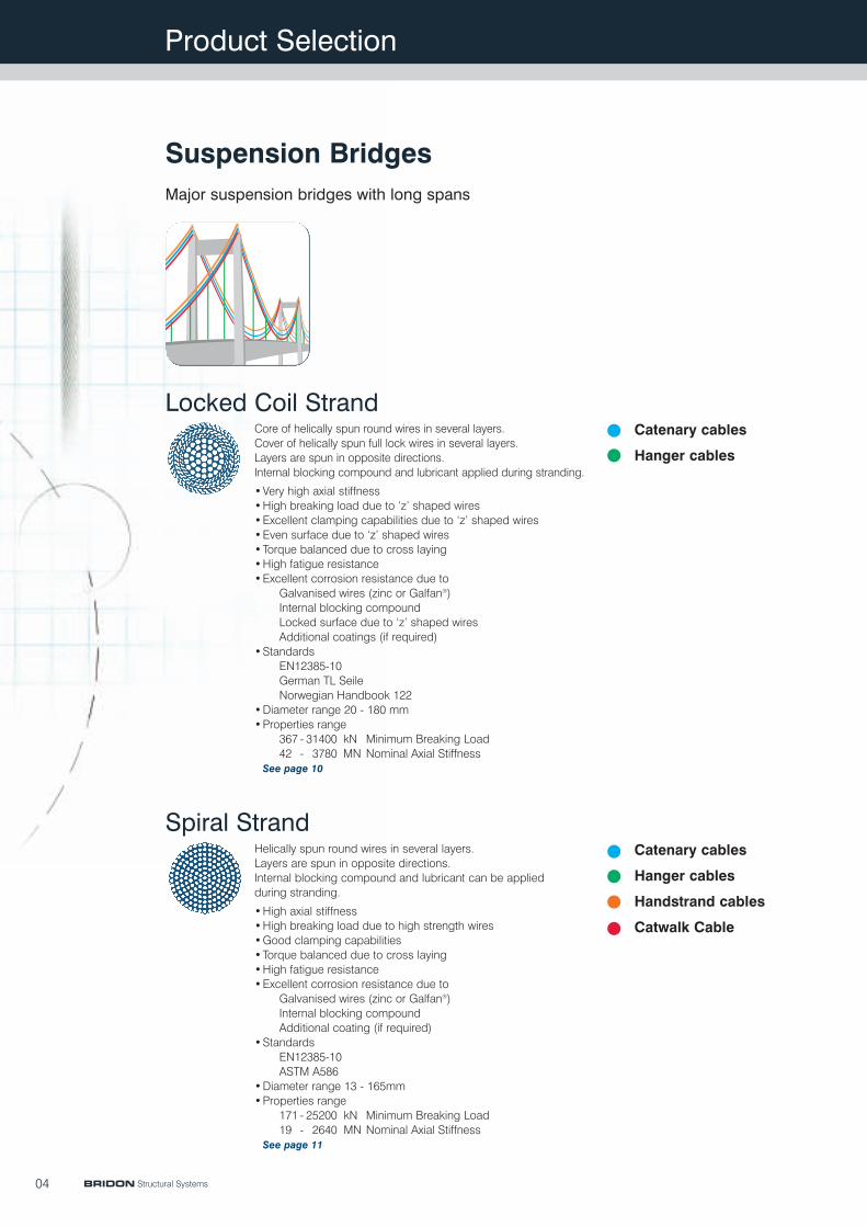
Suspension BridgesMajor suspension bridges with long spans
Catenary cables
Hanger cables
Core of helically spun round wires in several layers.Cover of helically spun full lock wires in several layers.Layers are spun in opposite directions.Internal blocking compound and lubricant applied during stranding.
•Very high axial stiffness•High breaking load due to ‘z’ shaped wires•Excellent clamping capabilities due to ‘z’ shaped wires•Even surface due to ‘z’ shaped wires•Torque balanced due to cross laying•High fatigue resistance•Excellent corrosion resistance due to
Galvanised wires (zinc or Galfan®)Internal blocking compoundLocked surface due to ‘z’ shaped wiresAdditional coatings (if required)
•StandardsEN12385-10German TL SeileNorwegian Handbook 122
•Diameter range 20 - 180 mm•Properties range
367 - 31400 kN Minimum Breaking Load42 - 3780 MN Nominal Axial Stiffness
See page 10
Catenary cables
Hanger cables
Handstrand cables
Catwalk Cable
Helically spun round wires in several layers.Layers are spun in opposite directions.Internal blocking compound and lubricant can be appliedduring stranding.
•High axial stiffness•High breaking load due to high strength wires•Good clamping capabilities•Torque balanced due to cross laying•High fatigue resistance•Excellent corrosion resistance due to
Galvanised wires (zinc or Galfan®)Internal blocking compoundAdditional coating (if required)
•StandardsEN12385-10ASTM A586
•Diameter range 13 - 165mm•Properties range
171 - 25200 kN Minimum Breaking Load19 - 2640 MN Nominal Axial Stiffness
See page 11
Locked Coil Strand
Spiral Strand
Product Selection
BRIDON Structural Systems 05
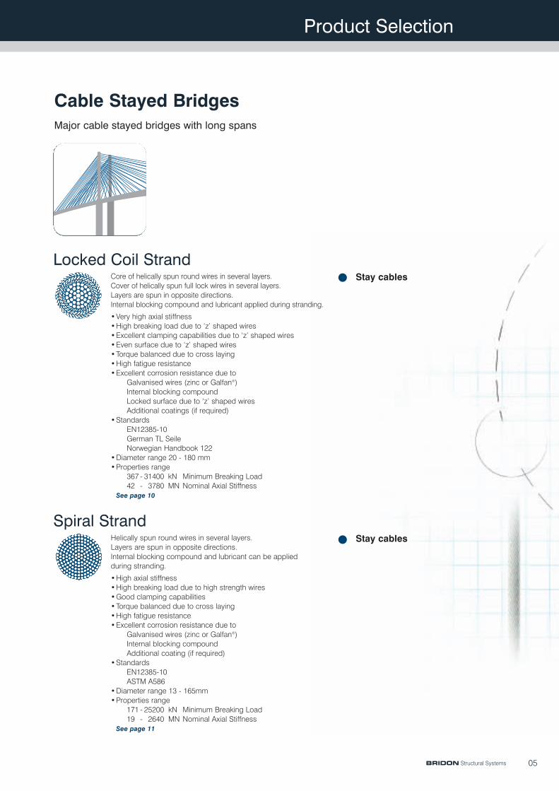
Cable Stayed BridgesMajor cable stayed bridges with long spans
Stay cablesCore of helically spun round wires in several layers.Cover of helically spun full lock wires in several layers.Layers are spun in opposite directions.Internal blocking compound and lubricant applied during stranding.
•Very high axial stiffness•High breaking load due to ‘z’ shaped wires•Excellent clamping capabilities due to ‘z’ shaped wires•Even surface due to ‘z’ shaped wires•Torque balanced due to cross laying•High fatigue resistance•Excellent corrosion resistance due to
Galvanised wires (zinc or Galfan®)Internal blocking compoundLocked surface due to ‘z’ shaped wiresAdditional coatings (if required)
•StandardsEN12385-10German TL SeileNorwegian Handbook 122
•Diameter range 20 - 180 mm•Properties range
367 - 31400 kN Minimum Breaking Load42 - 3780 MN Nominal Axial Stiffness
See page 10
Stay cablesHelically spun round wires in several layers.Layers are spun in opposite directions.Internal blocking compound and lubricant can be appliedduring stranding.
•High axial stiffness•High breaking load due to high strength wires•Good clamping capabilities•Torque balanced due to cross laying•High fatigue resistance•Excellent corrosion resistance due to
Galvanised wires (zinc or Galfan®)Internal blocking compoundAdditional coating (if required)
•StandardsEN12385-10ASTM A586
•Diameter range 13 - 165mm•Properties range
171 - 25200 kN Minimum Breaking Load19 - 2640 MN Nominal Axial Stiffness
See page 11
Locked Coil Strand
Spiral Strand
Product Selection
06
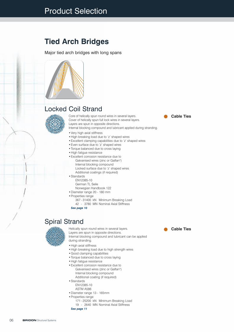
Tied Arch BridgesMajor tied arch bridges with long spans
Cable TiesCore of helically spun round wires in several layers.Cover of helically spun full lock wires in several layers.Layers are spun in opposite directions.Internal blocking compound and lubricant applied during stranding.
•Very high axial stiffness•High breaking load due to ‘z’ shaped wires•Excellent clamping capabilities due to ‘z’ shaped wires•Even surface due to ‘z’ shaped wires•Torque balanced due to cross laying•High fatigue resistance•Excellent corrosion resistance due to
Galvanised wires (zinc or Galfan®)Internal blocking compoundLocked surface due to ‘z’ shaped wiresAdditional coatings (if required)
•StandardsEN12385-10German TL SeileNorwegian Handbook 122
•Diameter range 20 - 180 mm•Properties range
367 - 31400 kN Minimum Breaking Load42 - 3780 MN Nominal Axial Stiffness
See page 10
Cable TiesHelically spun round wires in several layers.Layers are spun in opposite directions.Internal blocking compound and lubricant can be appliedduring stranding.
•High axial stiffness•High breaking load due to high strength wires•Good clamping capabilities•Torque balanced due to cross laying•High fatigue resistance•Excellent corrosion resistance due to
Galvanised wires (zinc or Galfan®)Internal blocking compoundAdditional coating (if required)
•StandardsEN12385-10ASTM A586
•Diameter range 13 - 165mm•Properties range
171 - 25200 kN Minimum Breaking Load19 - 2640 MN Nominal Axial Stiffness
See page 11
Locked Coil Strand
Spiral Strand
BRIDON Structural Systems
Catenary cables
Hanger cables
Stay cables
Catenary cables
Hanger cables
Stay cables
Product Selection
07
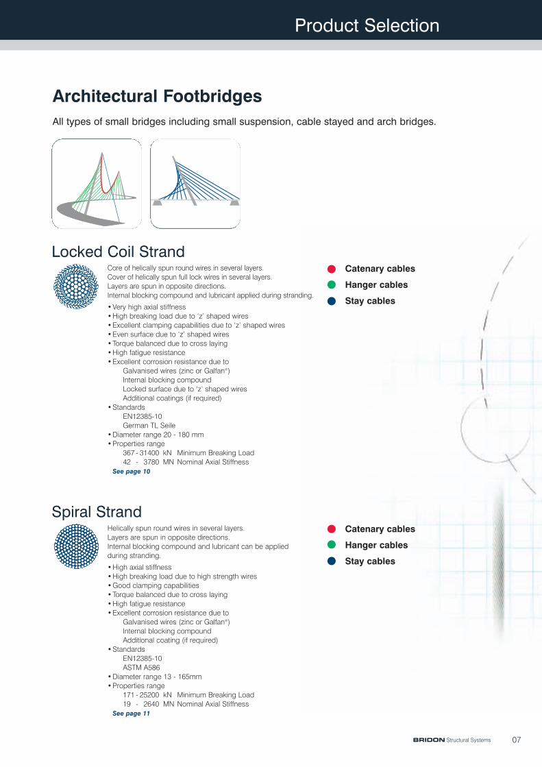
Architectural FootbridgesAll types of small bridges including small suspension, cable stayed and arch bridges.
Core of helically spun round wires in several layers.Cover of helically spun full lock wires in several layers.Layers are spun in opposite directions.Internal blocking compound and lubricant applied during stranding.
•Very high axial stiffness•High breaking load due to ‘z’ shaped wires•Excellent clamping capabilities due to ‘z’ shaped wires•Even surface due to ‘z’ shaped wires•Torque balanced due to cross laying•High fatigue resistance•Excellent corrosion resistance due to
Galvanised wires (zinc or Galfan®)Internal blocking compoundLocked surface due to ‘z’ shaped wiresAdditional coatings (if required)
•StandardsEN12385-10German TL Seile
•Diameter range 20 - 180 mm•Properties range
367 - 31400 kN Minimum Breaking Load42 - 3780 MN Nominal Axial Stiffness
See page 10
Helically spun round wires in several layers.Layers are spun in opposite directions.Internal blocking compound and lubricant can be appliedduring stranding.
•High axial stiffness•High breaking load due to high strength wires•Good clamping capabilities•Torque balanced due to cross laying•High fatigue resistance•Excellent corrosion resistance due to
Galvanised wires (zinc or Galfan®)Internal blocking compoundAdditional coating (if required)
•StandardsEN12385-10ASTM A586
•Diameter range 13 - 165mm•Properties range
171 - 25200 kN Minimum Breaking Load19 - 2640 MN Nominal Axial Stiffness
See page 11
Locked Coil Strand
Spiral Strand
BRIDON Structural Systems
Catenary cables
Hanger cables
Stay cables
Ring cables
Radial cables
Edge cables
Catenary cables
Hanger cables
Stay cables
Ring cables
Radial cables
Edge cables
Product Selection
08
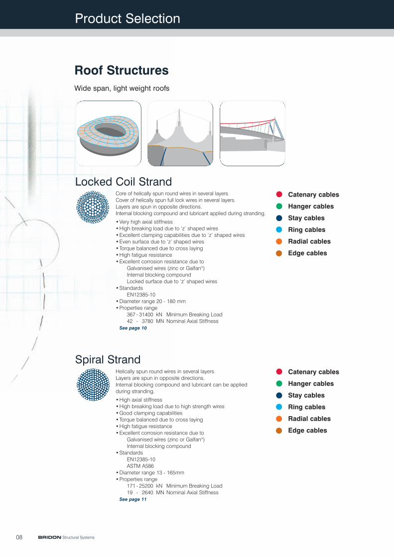
Roof StructuresWide span, light weight roofs
Core of helically spun round wires in several layers.Cover of helically spun full lock wires in several layers.Layers are spun in opposite directions.Internal blocking compound and lubricant applied during stranding.
•Very high axial stiffness•High breaking load due to ‘z’ shaped wires•Excellent clamping capabilities due to ‘z’ shaped wires•Even surface due to ‘z’ shaped wires•Torque balanced due to cross laying•High fatigue resistance•Excellent corrosion resistance due to
Galvanised wires (zinc or Galfan®)Internal blocking compoundLocked surface due to ‘z’ shaped wires
•StandardsEN12385-10
•Diameter range 20 - 180 mm•Properties range
367 - 31400 kN Minimum Breaking Load42 - 3780 MN Nominal Axial Stiffness
See page 10
Helically spun round wires in several layers.Layers are spun in opposite directions.Internal blocking compound and lubricant can be appliedduring stranding.
•High axial stiffness•High breaking load due to high strength wires•Good clamping capabilities•Torque balanced due to cross laying•High fatigue resistance•Excellent corrosion resistance due to
Galvanised wires (zinc or Galfan®)Internal blocking compound
•StandardsEN12385-10ASTM A586
•Diameter range 13 - 165mm•Properties range
171 - 25200 kN Minimum Breaking Load19 - 2640 MN Nominal Axial Stiffness
See page 11
Locked Coil Strand
Spiral Strand
BRIDON Structural Systems
09
Product Selection
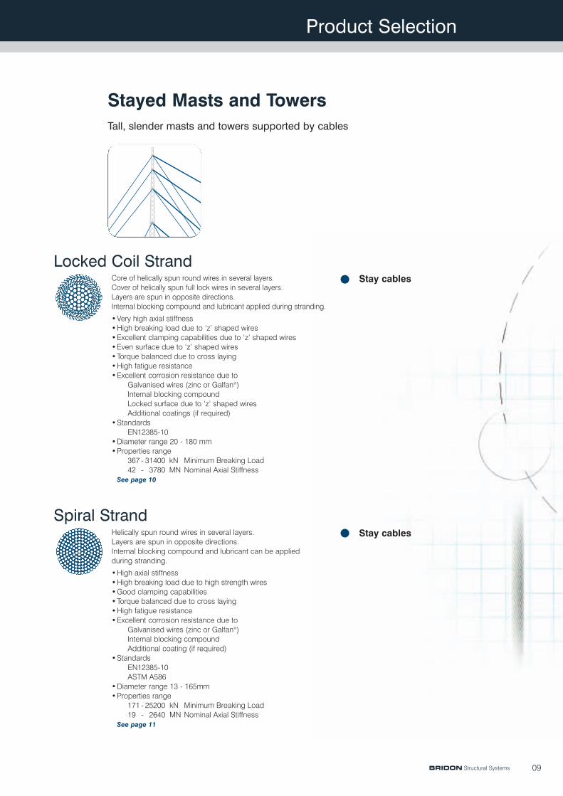
Stayed Masts and TowersTall, slender masts and towers supported by cables
Stay cables
Stay cables
Core of helically spun round wires in several layers.Cover of helically spun full lock wires in several layers.Layers are spun in opposite directions.Internal blocking compound and lubricant applied during stranding.
•Very high axial stiffness•High breaking load due to ‘z’ shaped wires•Excellent clamping capabilities due to ‘z’ shaped wires•Even surface due to ‘z’ shaped wires•Torque balanced due to cross laying•High fatigue resistance•Excellent corrosion resistance due to
Galvanised wires (zinc or Galfan®)Internal blocking compoundLocked surface due to ‘z’ shaped wiresAdditional coatings (if required)
•StandardsEN12385-10
•Diameter range 20 - 180 mm•Properties range
367 - 31400 kN Minimum Breaking Load42 - 3780 MN Nominal Axial Stiffness
See page 10
Helically spun round wires in several layers.Layers are spun in opposite directions.Internal blocking compound and lubricant can be appliedduring stranding.
•High axial stiffness•High breaking load due to high strength wires•Good clamping capabilities•Torque balanced due to cross laying•High fatigue resistance•Excellent corrosion resistance due to
Galvanised wires (zinc or Galfan®)Internal blocking compoundAdditional coating (if required)
•StandardsEN12385-10ASTM A586
•Diameter range 13 - 165mm•Properties range
171 - 25200 kN Minimum Breaking Load19 - 2640 MN Nominal Axial Stiffness
See page 11
Locked Coil Strand
Spiral Strand
BRIDON Structural Systems

Products
10
Product Code /Strand Diameter
Nominal MetallicCross Section
MinimumBreaking Load
Design Load GR,d =MBL / 1,5 / 1,1
Nominal AxialStiffness
NominalMetallic Mass
mm mm2kN kN MN kg/m
d AMBL GR,d EA Mass
LC 20LC 25LC 30LC 35LC 40LC 45LC 50LC 55LC 60LC 65LC 70LC 75LC 80LC 85LC 90LC 95LC 100LC 105LC 110LC 115LC 120LC 125LC 130LC 135LC 140LC 145LC 150LC 155LC 160LC 165LC 170LC 175LC 180
36857485811701580200024703020359042204890562063907220809091201010011100122001330014500157001620017500187002010021500230002450026100276002930031000
22334852070995812121497183021762558296434063873437649035527612167277394806187889515981810606113331218213030139391484815818167271775818788
426698133180229282345411482559642729824924104011501270140015301670182019602130229024602620280029903180337035703780
2.043.204.776.498.7611.113.716.820.023.527.231.335.540.145.050.756.261.968.074.581.188.495.6104112120128136145155164174184
254398594808109013901710209024902920339038904420500056006310699077108460928010100110001190012920139001491015900169901810019250204002165022900
Figures shown are for guidance purposes only. For details specific to your requirement please contact Bridon.
•Alternative sizes and constructions are availible to suit individual applications.•Minimising the number of different strand diameters can optimise costs.•All Stylite® sockets are suitable for use with Locked Coil Strand. See pages 12 - 23
•Swaged sockets are not suitable for use with Locked Coil Strand.•Strands with internal blocking material add 3% to nominal metallic mass.
Locked Coil Strand (LC)
BRIDON Structural Systems
Products
11
Product Code /Strand Diameter
Nominal MetallicCross Section
MinimumBreaking Load
Design Load GR,d =MBL / 1,5 / 1,1
Nominal AxialStiffness
NominalMetallic Mass
mm mm2kN kN MN kg/m
d AMBL GR,d EA Mass
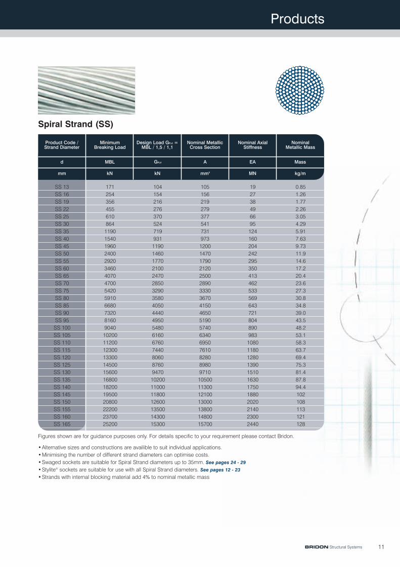
SS 13 171 104 0.85SS 16 254 154 1.26SS 19 356 216 1.77SS 22 455 276 2.26SS 25 610 370 3.05SS 30 864 524 4.29SS 35 1190 719 5.91SS 40 1540 931 7.63SS 45 1960 1190 9.73SS 50 2400 1460 11.9SS 55 2920 1770 14.6SS 60 3460 2100 17.2SS 65 4070 2470 20.4SS 70 4700 2850 23.6SS 75 5420 3290 27.3SS 80 5910 3580 30.8SS 85 6680 4050 34.8SS 90 7320 4440 39.0SS 95 8160 4950 43.5SS 100 9040 5480 48.2SS 105 10200 6160 53.1SS 110 11200 6760 58.3SS 115 12300 7440 63.7SS 120 13300 8060 69.4SS 125 14500 8760 75.3SS 130 15600 9470 81.4SS 135 16800 10200 87.8SS 140 18200 11000 94.4SS 145 19500 11800 102SS 150 20800 12600 108SS 155 22200 13500 113SS 160 23700 14300 121SS 165 25200 15300 128
10515621927937754173197312001470179021202500289033303670415046505190574063406950761082808980971010500113001210013000138001480015700
192738496695124160204242295350413462533569643721804890983108011801280139015101630175018802020214023002440
Figures shown are for guidance purposes only. For details specific to your requirement please contact Bridon.
•Alternative sizes and constructions are availible to suit individual applications.•Minimising the number of different strand diameters can optimise costs.•Swaged sockets are suitable for Spiral Strand diameters up to 35mm. See pages 24 - 29
•Stylite® sockets are suitable for use with all Spiral Strand diameters. See pages 12 - 23
•Strands with internal blocking material add 4% to nominal metallic mass
Spiral Strand (SS)
BRIDON Structural Systems

Products
12
Product Code /Strand Diameter
mm
Max Min Pin Socket Pin+Caps
mm mm
Pin Hole
mm kg kg
L1 L2 L3 L5L4L6 ø1 Weight
ST-F 25 275 88 121 73 58 57 55 45 8 1.7ST-F 30 330 105 154 86 70 71 68 55 15.5 2.9ST-F 35 385 120 175 100 82.5 85 79 65 22.5 4.7ST-F 40 410 130 187 120 95 90 82 75 31.5 6.6ST-F 45 420 145 210 124 100 95 90 80 43 8.4ST-F 50 440 155 221 144 115 100 93 90 56 11ST-F 55 477 168 233 155 115 110 100 100 60 14ST-F 60 520 180 250 168 125 120 110 110 74 18ST-F 65 565 195 267 187 137 129 115 120 94 24ST-F 70 610 210 285 202 148 137 125 130 117 30ST-F 75 645 225 307 211 154 147 135 135 141 34ST-F 80 690 240 322 226 166 157 145 145 167 42ST-F 85 735 255 348 240 177 167 155 155 209 51ST-F 90 780 270 366 255 188 178 165 165 245 61ST-F 95 825 285 383 274 200 186 175 175 291 72ST-F 100 870 300 421 294 211 197 185 185 352 87ST-F 105 905 315 438 298 218 206 195 190 394 96ST-F 110 950 330 458 318 228 215 205 200 457 112ST-F 115 995 345 474 332 240 225 215 210 517 128ST-F 120 1035 365 482 347 255 235 225 220 578 144ST-F 125 1080 375 501 361 266 245 230 230 649 164ST-F 130 1140 385 524 396 273 257 240 235 740 178ST-F 135 1185 400 539 410 279 267 250 240 825 192ST-F 140 1230 415 557 430 290 277 260 250 920 215ST-F 145 1276 425 575 445 306 287 270 260 1009 239ST-F 150 1321 440 587 465 315 297 280 270 1099 265
465666768191101111121131136146156166176186191201211221231237242252262272
Figures shown are for guidance purposes only. For details specific to your requirement please contact Bridon.
•Suitable for Locked Coil Strand and Spiral Strand•Architectural socket design•100% efficiency, transmits the whole strand force
Steelwork dimensions for guidance purposes:L4 maximum swing of connecting linkageL6 width of connecting steelwork including protective coating e.g. paint, galvanising, etc.
For strand diameters larger than 150mm contact Bridon.
Stylite Fork Sockets (ST-F)
mmmmmmmmmmmm
BRIDON Structural Systems
L1
L 2
L 3 L 6
L4
L5
ø1

Products
13
465666768191101111121131136146156166176186191201211221231237242252262272
Figures shown are for guidance purposes only. For details specific to your requirement please contact Bridon.
•Suitable for Locked Coil Strand and Spiral Strand•Architectural socket design•100% efficiency, transmits the whole strand force
Steelwork dimensions for guidance purposes:L4 maximum swing of connecting linkageL6 width of connecting steelwork including protective coating e.g. paint, galvanising, etc.
For strand diameters larger than 150mm contact Bridon.
Product Code /Strand Diameter
ADJT+/- L3 L4 L5
mmmm mm mm mm mm mm mm mm mm mm mm kgMetric
MaxMax Min Min Pin PinHole
ThreadSize
Assy
L6L1 ø1ø2
Weight
ST-AF 25 631 531 50 121 73 58 57 55 45 87 M42 x 4.5 20ST-AF 30 701 601 50 154 86 70 71 68 55 108 M52 x 5.0 36ST-AF 35 815 695 60 175 100 82.5 85 79 65 120 M60 x 5.5 49ST-AF 40 865 745 60 187 120 95 90 82 75 135 M68 x 6.0 69ST-AF 45 894 774 60 210 124 100 95 90 80 145 M76 x 6.0 87ST-AF 50 974 834 70 221 144 115 100 93 90 155 M80 x 6.0 112ST-AF 55 1030 890 70 233 155 115 110 100 100 170 M90 x 6.0 131ST-AF 60 1088 948 70 250 168 125 120 110 110 185 M95 x 6.0 163ST-AF 65 1161 1021 70 267 187 137 129 115 120 205 M105 x 6.0 210ST-AF 70 1247 1087 80 285 202 148 137 125 130 220 M105 x 6.0 260ST-AF 75 1316 1156 80 307 211 154 147 135 135 235 M115 x 6.0 309ST-AF 80 1416 1236 90 322 226 166 157 145 145 245 M120 x 6.0 365ST-AF 85 1480 1300 90 348 240 177 167 155 155 265 M125 x 6.0 447ST-AF 90 1590 1390 100 366 255 188 178 165 165 270 M135 x 6.0 514ST-AF 95 1644 1444 100 383 274 200 186 175 175 285 M140 x 6.0 591ST-AF 100 1764 1544 110 421 294 211 197 185 185 300 M150 x 6.0 700ST-AF 105 1853 1613 120 438 298 218 206 195 190 315 M155 x 6.0 816ST-AF 110 1983 1723 130 458 318 228 215 205 200 330 M165 x 6.0 942ST-AF 115 2077 1797 140 474 332 240 225 215 210 345 M175 x 6.0 1084ST-AF 120 2152 1872 140 482 347 255 235 225 220 360 M185 x 6.0 1224ST-AF 125 2246 1946 150 501 361 266 245 230 230 375 M190 x 6.0 1364ST-AF 130 2321 2021 150 524 396 273 257 240 235 390 M195 x 6.0 1513ST-AF 135 2417 2097 160 539 410 279 267 250 240 400 M200 x 6.0 1741ST-AF 140 2485 2165 160 557 430 290 277 260 250 415 M205 x 6.0 1929ST-AF 145 2610 2260 175 575 445 306 287 270 260 430 M215 x 6.0 2147ST-AF 150 2670 2320 175 587 465 315 297 280 270 445 M220 x 6.0 2340
Stylite Adjustable Fork Sockets (ST-AF)
BRIDON Structural Systems
L1
L 3 L 6
L4
L5
ø 2
ø1

Products
14
Figures shown are for guidance purposes only. For details specific to your requirement please contact Bridon.
•Suitable for Locked Coil Strand and Spiral Strand•Architectural socket design•100% efficiency, transmits the whole strand force
For strand diameters larger than 150mm contact Bridon.
Product Code /Strand Diameter L1 L5 L6 Thread Size Weight
(Not Including Bar)
mm mm mm mm Metric kg
ST-FA 25 155 58 56 M42 x 4.5 5ST-FA 30 190 70 70 M52 x 5.0 9ST-FA 35 210 82 80 M60 x 5.5 13ST-FA 40 240 95 85 M68 x 6.0 18ST-FA 45 260 100 90 M72 x 6.0 25ST-FA 50 285 115 95 M80 x 6.0 32ST-FA 55 300 115 107 M90 X 6.0 44ST-FA 60 325 125 115 M95 X 6.0 54ST-FA 65 355 137 120 M105 x 6.0 68ST-FA 70 365 148 130 M105 x 6.0 80ST-FA 75 395 154 140 M115 x 6.0 98ST-FA 80 415 166 150 M120 x 6.0 117ST-FA 85 440 177 160 M125 x 6.0 136ST-FA 90 470 188 170 M135 x 6.0 165ST-FA 95 495 200 180 M140 x 6.0 195ST-FA 100 525 211 190 M150 x 6.0 237ST-FA 105 541 218 200 M155 x 6.0 261ST-FA 110 570 228 210 M165 x 6.0 299ST-FA 115 600 240 220 M175 x 6.0 348ST-FA 120 635 255 230 M185 x 6.0 411ST-FA 125 660 266 240 M190 x 6.0 463ST-FA 130 680 273 250 M195 x 6.0 492ST-FA 135 700 279 260 M200 x 6.0 532ST-FA 140 720 290 270 M205 x 6.0 589ST-FA 145 750 303 280 M215 x 6.0 652ST-FA 150 775 315 290 M220 X 6.0 726
Stylite Fork Socket Adapter Bar (ST-FA)
BRIDON Structural Systems
L1
L5L 6
15
Products
Product Code /Strand Diameter
mm mm mm mm kg
L2 ø1 ø2 Weight
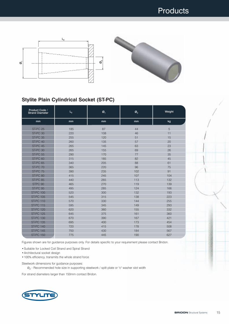
ST-PC 25 185 87 44 5ST-PC 30 220 108 46 11ST-PC 35 255 120 51 15ST-PC 40 260 135 57 20ST-PC 45 265 145 63 23ST-PC 30 265 155 69 26ST-PC 55 290 170 77 35ST-PC 60 315 185 82 45ST-PC 65 340 205 88 61ST-PC 70 365 220 96 75ST-PC 75 390 235 102 91ST-PC 80 415 245 107 104ST-PC 85 440 265 113 132STPC 90 465 270 119 139ST-PC 95 495 285 124 166ST-PC 100 520 300 132 193ST-PC 105 545 315 138 223ST-PC 110 570 330 144 255ST-PC 115 595 345 149 293ST-PC 120 620 360 155 332ST-PC 125 645 375 161 360ST-PC 130 670 390 167 421ST-PC 135 695 400 173 454ST-PC 140 720 415 178 508ST-PC 145 750 430 184 567ST-PC 150 775 445 190 627
Stylite Plain Cylindrical Socket (ST-PC)
Figures shown are for guidance purposes only. For details specific to your requirement please contact Bridon.
•Suitable for Locked Coil Strand and Spiral Strand•Architectural socket design•100% efficiency, transmits the whole strand force
Steelwork dimensions for guidance purposes:ø2 - Recommended hole size in supporting steelwork / split plate or "c" washer slot width
For strand diameters larger than 150mm contact Bridon.
BRIDON Structural Systems
L2
ø 1 ø 2
Products
16
Product Code /Strand Diameter
mm mm mm mm mm Metric kg
L2 L3 ø1 ø2 Thread Size Weight
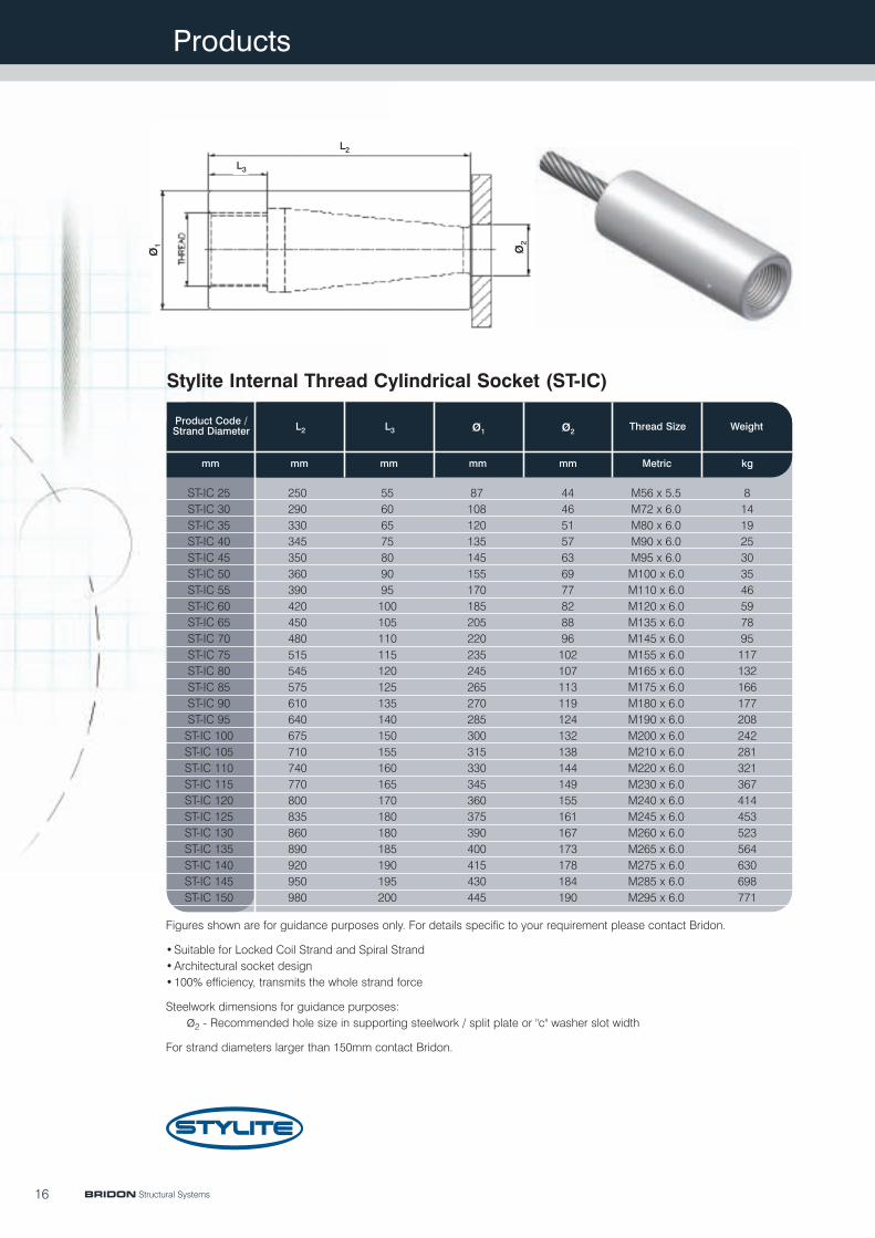
ST-IC 25 250 55 87 M56 x 5.5 8ST-IC 30 290 60 108 M72 x 6.0 14ST-IC 35 330 65 120 M80 x 6.0 19ST-IC 40 345 75 135 M90 x 6.0 25ST-IC 45 350 80 145 M95 x 6.0 30ST-IC 50 360 90 155 M100 x 6.0 35ST-IC 55 390 95 170 M110 x 6.0 46ST-IC 60 420 100 185 M120 x 6.0 59ST-IC 65 450 105 205 M135 x 6.0 78ST-IC 70 480 110 220 M145 x 6.0 95ST-IC 75 515 115 235 M155 x 6.0 117ST-IC 80 545 120 245 M165 x 6.0 132ST-IC 85 575 125 265 M175 x 6.0 166ST-IC 90 610 135 270 M180 x 6.0 177ST-IC 95 640 140 285 M190 x 6.0 208ST-IC 100 675 150 300 M200 x 6.0 242ST-IC 105 710 155 315 M210 x 6.0 281ST-IC 110 740 160 330 M220 x 6.0 321ST-IC 115 770 165 345 M230 x 6.0 367ST-IC 120 800 170 360 M240 x 6.0 414ST-IC 125 835 180 375 M245 x 6.0 453ST-IC 130 860 180 390 M260 x 6.0 523ST-IC 135 890 185 400 M265 x 6.0 564ST-IC 140 920 190 415 M275 x 6.0 630ST-IC 145 950 195 430 M285 x 6.0 698ST-IC 150 980 200 445 M295 x 6.0 771
Stylite Internal Thread Cylindrical Socket (ST-IC)
Figures shown are for guidance purposes only. For details specific to your requirement please contact Bridon.
•Suitable for Locked Coil Strand and Spiral Strand•Architectural socket design•100% efficiency, transmits the whole strand force
Steelwork dimensions for guidance purposes:ø2 - Recommended hole size in supporting steelwork / split plate or "c" washer slot width
For strand diameters larger than 150mm contact Bridon.
44465157636977828896102107113119124132138144149155161167173178184190
BRIDON Structural Systems
L2
L3
ø 1 ø 2
Products
17
Product Code /Strand Diameter
mm mm mm mm mm mm mm mm Metric kg kg
Socket NutL2 L3 L4 L5 ø1 ø2 ø3
ThreadSize
Weight
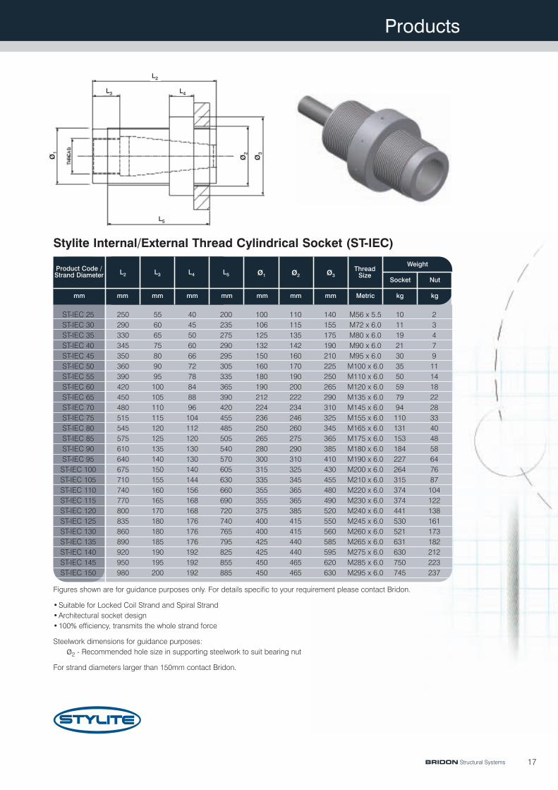
ST-IEC 25 250 55 40 100 110 140 10 2ST-IEC 30 290 60 45 106 115 155 11 3ST-IEC 35 330 65 50 125 135 175 19 4ST-IEC 40 345 75 60 132 142 190 21 7ST-IEC 45 350 80 66 150 160 210 30 9ST-IEC 50 360 90 72 160 170 225 35 11ST-IEC 55 390 95 78 180 190 250 50 14ST-IEC 60 420 100 84 190 200 265 59 18ST-IEC 65 450 105 88 212 222 290 79 22ST-IEC 70 480 110 96 224 234 310 94 28ST-IEC 75 515 115 104 236 246 325 110 33ST-IEC 80 545 120 112 250 260 345 131 40ST-IEC 85 575 125 120 265 275 365 153 48ST-IEC 90 610 135 130 280 290 385 184 58ST-IEC 95 640 140 130 300 310 410 227 64ST-IEC 100 675 150 140 315 325 430 264 76ST-IEC 105 710 155 144 335 345 455 315 87ST-IEC 110 740 160 156 355 365 480 374 104ST-IEC 115 770 165 168 355 365 490 374 122ST-IEC 120 800 170 168 375 385 520 441 138ST-IEC 125 835 180 176 400 415 550 530 161ST-IEC 130 860 180 176 400 415 560 521 173ST-IEC 135 890 185 176 425 440 585 631 182ST-IEC 140 920 190 192 425 440 595 630 212ST-IEC 145 950 195 192 450 465 620 750 223ST-IEC 150 980 200 192 450 465 630 745 237
Stylite Internal/External Thread Cylindrical Socket (ST-IEC)
Figures shown are for guidance purposes only. For details specific to your requirement please contact Bridon.
•Suitable for Locked Coil Strand and Spiral Strand•Architectural socket design•100% efficiency, transmits the whole strand force
Steelwork dimensions for guidance purposes:ø2 - Recommended hole size in supporting steelwork to suit bearing nut
For strand diameters larger than 150mm contact Bridon.
M56 x 5.5M72 x 6.0M80 x 6.0M90 x 6.0M95 x 6.0M100 x 6.0M110 x 6.0M120 x 6.0M135 x 6.0M145 x 6.0M155 x 6.0M165 x 6.0M175 x 6.0M180 x 6.0M190 x 6.0M200 x 6.0M210 x 6.0M220 x 6.0M230 x 6.0M240 x 6.0M245 x 6.0M260 x 6.0M265 x 6.0M275 x 6.0M285 x 6.0M295 x 6.0
200235275290295305335365390420455485505540570605630660690720740765795825855885
BRIDON Structural Systems
L2
L3 L4
L5
ø 1 ø 2 ø 3
Products
18
Figures shown are for guidance purposes only. For details specific to your requirement please contact Bridon.
•Suitable for Locked Coil Strand and Spiral Strand•Architectural socket design•100% efficiency, transmits the whole strand force
For strand diameters larger than 150mm contact Bridon.
Product Code /Strand Diameter
kgMetricmm mmmmmmmm
L2 L3 ø2ø1 Thread Size Weight
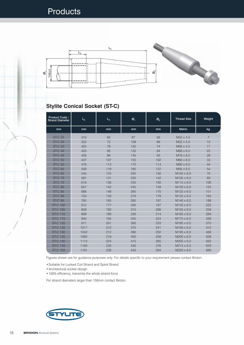
ST-C 25 87 M42 x 4.5ST-C 30 108 M52 x 5.0ST-C 35 120 M60 x 5.5ST-C 40 135 M68 x 6.0ST-C 45 145 M76 x 6.0ST-C 50 155 M80 x 6.0ST-C 55 170 M90 x 6.0ST-C 60 185 M95 x 6.0ST-C 65 205 M105 x 6.0ST-C 70 220 M105 x 6.0ST-C 75 235 M115 x 6.0ST-C 80 245 M120 x 6.0ST-C 85 265 M125 x 6.0ST-C 90 270 M135 x 6.0ST-C 95 285 M140 x 6.0ST-C 100 300 M150 x 6.0ST-C 105 315 M155 x 6.0ST-C 110 330 M165 x 6.0ST-C 115 345 M175 x 6.0ST-C 120 360 M185 x 6.0ST-C 125 375 M190 x 6.0ST-C 130 390 M195 x 6.0ST-C 135 400 M200 x 6.0ST-C 140 415 M205 x 6.0ST-C 145 430 M215 x 6.0ST-C 150 445 M220 x 6.0
310352404420426447478509545581616657688734765812858899940971101710421083111411601191
7121722283344547089106122151163188222258294336375412468508562629689
6572799096107113119125131136142148159165177183189195201212212218224230236
5866748493102114122130142150159170179187197206214224233241250258265276284
Stylite Conical Socket (ST-C)
BRIDON Structural Systems
L2L3
ø 1 ø 2
Products
19
Figures shown are for guidance purposes only. For details specific to your requirement please contact Bridon.
•Suitable for Locked Coil Strand and Spiral Strand•Architectural socket design•100% efficiency, transmits the whole strand force
For strand diameters larger than 150mm contact Bridon.
Product Code /Strand Diameter
mm Metricmm mm
Max Min
mm kg
Thread SizeL2 Max Adjustment
+/- Weight
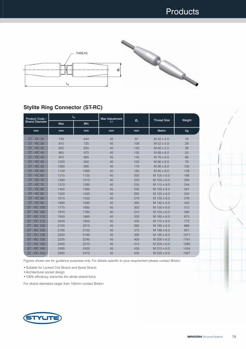
ST - RC 25 45 16ST - RC 30 45 29ST - RC 35 45 39ST - RC 40 45 53ST - RC 45 45 66ST - RC 50 45 79ST - RC 55 45 105ST - RC 60 45 128ST - RC 65 45 166ST - RC 70 45 205ST - RC 75 45 244ST - RC 80 45 281ST - RC 85 45 343ST - RC 90 45 376ST - RC 95 45 432ST - RC 100 45 512ST - RC 105 45 590ST - RC 110 45 675ST - RC 115 45 772ST - RC 120 45 866ST - RC 125 45 951ST - RC 130 45 1071ST - RC 135 45 1161ST - RC 140 45 1280ST - RC 145 45 1434ST - RC 150 45 1567
M 42 x 4.5M 52 x 5.0M 60 x 5.5M 68 x 6.0M 76 x 6.0M 80 x 6.0M 90 x 6.0M 95 x 6.0M 105 x 6.0M 105 x 6.0M 115 x 6.0M 120 x 6.0M 125 x 6.0M 135 x 6.0M 140 x 6.0M 150 x 6.0M 155 x 6.0M 165 x 6.0M 175 x 6.0M 185 x 6.0M 190 x 6.0M 195 x 6.0M 200 x 6.0M 205 x 6.0M 215 x 6.0M 220 x 6.0
730815925965975102010851150121513001370145515201615168017751870195520402105219522502335240024952560
6407258358758859309951060112512101280136514301525159016851780186519502015210521602245231024052470
Stylite Ring Connector (ST-RC)
BRIDON Structural Systems
mm
ø1
87108120135145155170185205220235245265270285300315330345360375390400415430445
L2
ø 1

Products
20
Figures shown are for guidance purposes only. For details specific to your requirement please contact Bridon.
•Suitable for Locked Coil Strand and Spiral Strand•Architectural socket design•100% efficiency, transmits the whole strand force
For strand diameters larger than 150mm contact Bridon.
Product Code /Strand Diameter
mm mm mm mm mm Metric kg
L1 L2 L3 L4 Thread Size Weight
ST-B 25 160 185 87 232 M 30 x 3.5ST-B 30 180 220 105 264 M 36 x 4.0ST-B 35 200 255 125 296 M 42 x 4.5ST-B 40 215 260 140 327 M 48 x 5.0ST-B 45 250 265 145 378 M 56 x 5.5ST-B 50 260 265 155 404 M 64 x 6.0ST-B 55 300 290 170 444 M 64 x 6.0ST-B 60 320 315 185 480 M 68 x 6.0ST-B 65 340 340 205 500 M 76 x 6.0ST-B 70 385 365 220 565 M 80 x 6.0ST-B 75 390 395 240 570 M 85 x 6.0ST-B 80 400 415 245 600 M 90 x 6.0ST-B 85 430 440 265 630 M 95 x 6.0ST-B 90 475 465 270 695 M 100 x 6.0ST-B 95 480 495 285 700 M 105 x 6.0ST-B 100 560 520 300 800 M 110 x 6.0ST-B 105 565 545 315 815 M 115 x 6.0ST-B 110 570 570 330 830 M 120 x 6.0ST-B 115 580 595 345 860 M 125 x 6.0ST-B 120 585 620 360 875 M 130 x 6.0ST-B 125 590 645 375 890 M 135 x 6.0ST-B 130 630 670 390 945 M 140 x 6.0ST-B 135 650 695 400 970 M 145 x 6.0ST-B 140 670 720 415 1000 M 150 x 6.0ST-B 145 695 750 430 1035 M 155 x 6.0ST-B 150 720 775 445 1070 M 160 x 6.0
Stylite Block Socket (ST-B)
1524374762729512314319521825630036840052858464373680587510101106122613691509
BRIDON Structural Systems
L 1
L2L3
L 4

Products
21
Figures shown are for guidance purposes only. For details specific to your requirement please contact Bridon.
•Suitable for Locked Coil Strand and Spiral Strand•Architectural socket design•100% efficiency, transmits the whole strand force
Steelwork dimensions for guidance purposes:L4 maximum swing of connecting linkageL6 width of connecting steelwork including protective coating e.g. paint, galvanising, etc.
For strand diameters larger than 150mm contact Bridon.
Product Code /Strand Diameter
mm mm mm mm mm mm mm mm mm mm mm mm Metric
Max Min
ThreadSizeL1 L2 L3 L4 L5 L7 L8 L9
ø1Pin Pin
Hole
mm
L6
ST-CH 25 160 72 121 73 66 56 55 145 232 211 45ST-CH 30 180 84 154 86 74 71 68 170 264 244 55ST-CH 35 200 96 175 100 87 85 79 210 296 297 65ST-CH 40 215 112 187 120 98 90 82 225 327 323 75ST-CH 45 250 128 210 124 106 95 90 250 378 356 80ST-CH 50 260 144 221 144 120 100 93 280 404 400 90ST-CH 55 300 144 233 155 132 110 100 310 444 442 100ST-CH 60 320 160 250 168 141 120 110 335 480 476 110ST-CH 65 340 160 267 187 155 129 115 365 500 520 120ST-CH 70 385 180 285 202 167 137 125 390 565 557 130ST-CH 75 390 180 307 211 175 147 135 410 570 585 135ST-CH 80 400 200 322 226 188 157 145 440 600 628 145ST-CH 85 430 200 348 240 203 167 155 470 630 673 155ST-CH 90 475 220 366 255 216 178 165 500 695 716 165ST-CH 95 480 220 383 274 232 186 175 525 700 757 175ST-CH 100 560 240 421 294 245 197 185 565 800 810 185ST-CH 105 565 250 438 298 252 206 195 580 815 832 190ST-CH 110 570 260 458 318 262 215 205 605 830 867 200ST-CH 115 580 280 474 332 277 225 215 635 860 912 210ST-CH 120 585 290 482 347 289 235 225 660 875 949 220ST-CH 125 590 300 501 361 303 245 230 680 890 983 230ST-CH 130 630 315 524 396 273 257 240 676 945 949 235ST-CH 135 650 325 539 410 279 267 250 715 975 994 240ST-CH 140 670 340 557 430 290 277 260 740 1010 1030 250ST-CH 145 695 345 575 445 306 287 270 775 1040 1081 260ST-CH 150 720 360 587 465 315 297 280 800 1080 1115 270
Stylite Crossheads (ST-CH)
M 30 x 3.5M 36 x 4.0M 42 x 4.5M 48 x 5.0M 56 x 5.5M 64 x 6.0M 64 x 6.0M 68 x 6.0M 76 x 6.0M 80 x 6.0M 85 x 6.0M 90 x 6.0M 95 x 6.0M 100 x 6.0M 105 x 6.0M 110 x 6.0M 115 x 6.0M 120 x 6.0M 125 x 6.0M 130 x 6.0M 135 x 6.0M 135 x 6.0M 140 x 6.0M 145 x 6.0M 150 x 6.0M 155 x 6.0
465666768191101111121131136146156166176186191201211221231237242252262272
BRIDON Structural Systems
L 1
L2
L 3
L4 L5L7L9
L 8L 6
ø1
Products
22
Product Code /Strand Diameter
mm mm mm mm mm mm kg
L2 L4 L5 L6 ø1 Weight
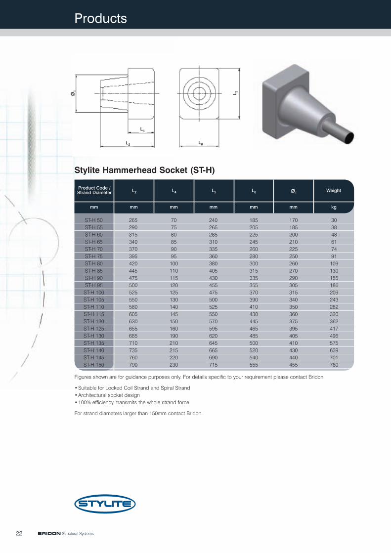
ST-H 50 265 240 185ST-H 55 290 265 205ST-H 60 315 285 225ST-H 65 340 310 245ST-H 70 370 335 260ST-H 75 395 360 280ST-H 80 420 380 300ST-H 85 445 405 315ST-H 90 475 430 335ST-H 95 500 455 355ST-H 100 525 475 370ST-H 105 550 500 390ST-H 110 580 525 410ST-H 115 605 550 430ST-H 120 630 570 445ST-H 125 655 595 465ST-H 130 685 620 485ST-H 135 710 645 500ST-H 140 735 665 520ST-H 145 760 690 540ST-H 150 790 715 555
707580859095100110115120125130140145150160190210215220230
170185200210225250260270290305315340350360375395405410430440455
303848617491109130155186209243282320362417496575639701780
Stylite Hammerhead Socket (ST-H)
Figures shown are for guidance purposes only. For details specific to your requirement please contact Bridon.
•Suitable for Locked Coil Strand and Spiral Strand•Architectural socket design•100% efficiency, transmits the whole strand force
For strand diameters larger than 150mm contact Bridon.
BRIDON Structural Systems
L2
L4
L 5
L6
ø 1
Products
23
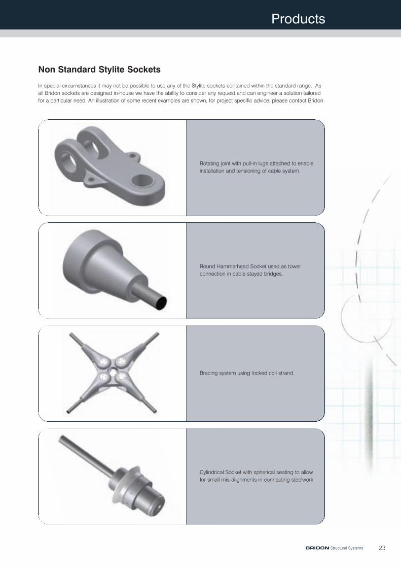
Non Standard Stylite Sockets
In special circumstances it may not be possible to use any of the Stylite sockets contained within the standard range. Asall Bridon sockets are designed in-house we have the ability to consider any request and can engineer a solution tailoredfor a particular need. An illustration of some recent examples are shown, for project specific advice, please contact Bridon.
BRIDON Structural Systems
Rotating joint with pull-in lugs attached to enableinstallation and tensioning of cable system.
Round Hammerhead Socket used as towerconnection in cable stayed bridges.
Bracing system using locked coil strand.
Cylindrical Socket with spherical seating to allowfor small mis-alignments in connecting steelwork
Products
24
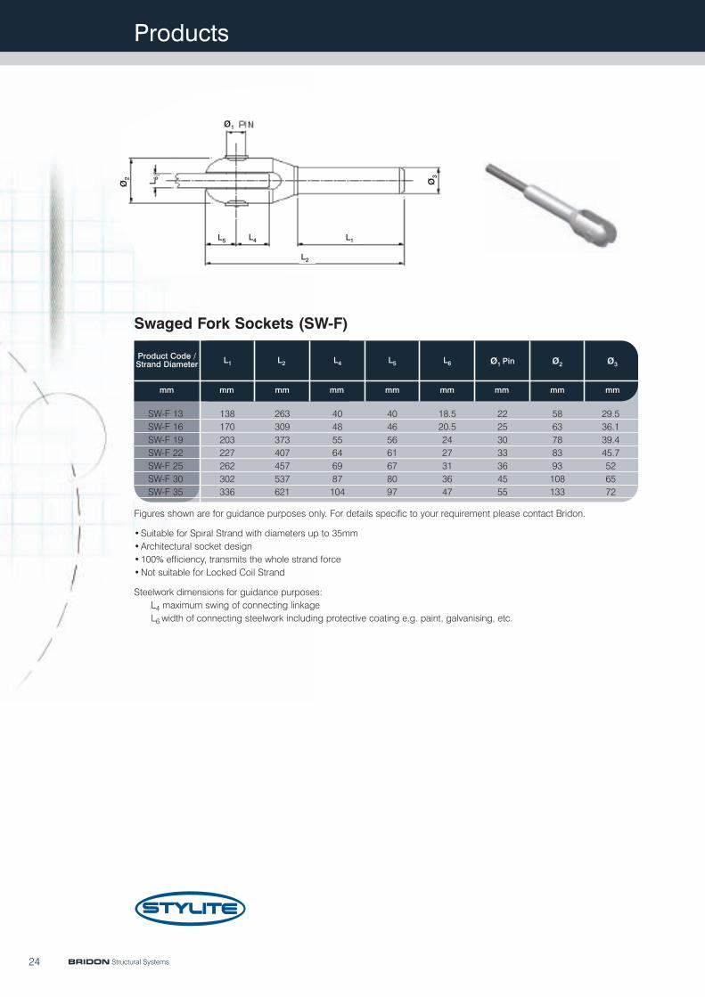
Figures shown are for guidance purposes only. For details specific to your requirement please contact Bridon.
•Suitable for Spiral Strand with diameters up to 35mm•Architectural socket design•100% efficiency, transmits the whole strand force•Not suitable for Locked Coil Strand
Steelwork dimensions for guidance purposes:L4 maximum swing of connecting linkageL6 width of connecting steelwork including protective coating e.g. paint, galvanising, etc.
Product Code /Strand Diameter
mm mm mm mm mm mm mm mmmm
L1 L2 L4 L5 ø2L6 ø1 Pin ø3
SW-F 13SW-F 16SW-F 19SW-F 22SW-F 25SW-F 30SW-F 35
138170203227262302336
263309373407457537621
404855646987104
40465661678097
18.520.52427313647
22253033364555
5863788393108133
29.536.139.445.7526572
Swaged Fork Sockets (SW-F)
BRIDON Structural Systems
L1
L2
L4L5
L 6
ø1
ø 3ø 2
Products
25
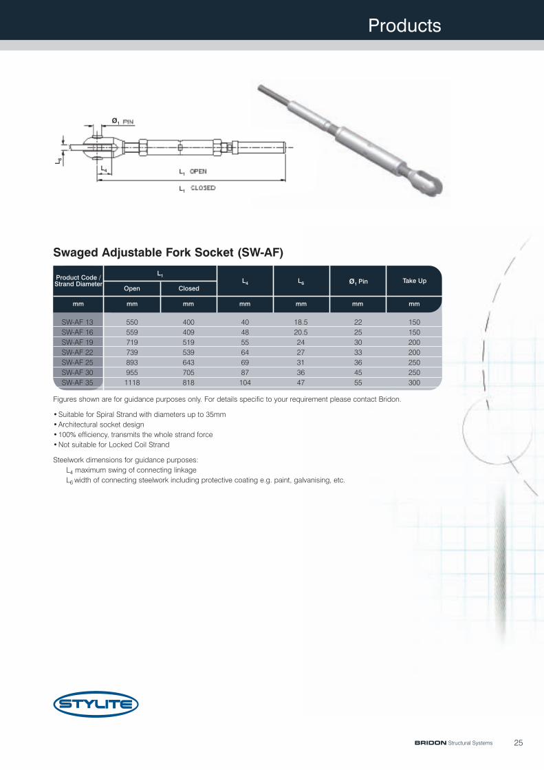
Figures shown are for guidance purposes only. For details specific to your requirement please contact Bridon.
•Suitable for Spiral Strand with diameters up to 35mm•Architectural socket design•100% efficiency, transmits the whole strand force•Not suitable for Locked Coil Strand
Steelwork dimensions for guidance purposes:L4 maximum swing of connecting linkageL6 width of connecting steelwork including protective coating e.g. paint, galvanising, etc.
Product Code /Strand Diameter
mm mm mm mm mm mmmm
L1
Open ClosedL4 L6 ø1 Pin Take Up
SW-AF 13SW-AF 16SW-AF 19SW-AF 22SW-AF 25SW-AF 30SW-AF 35
5505597197398939551118
400409519539643705818
404855646987104
18.520.52427313647
22253033364555
150150200200250250300
Swaged Adjustable Fork Socket (SW-AF)
BRIDON Structural Systems
L1
L1
L4
L 6
ø1

Products
26
Figures shown are for guidance purposes only. For details specific to your requirement please contact Bridon.
•Suitable for Spiral Strand with diameters up to 35mm•Architectural socket design•100% efficiency, transmits the whole strand force•Not suitable for Locked Coil Strand
Product Code /Strand Diameter
mmmmmmmmmmmmmmmmmm
L1 L2 L3 L4 L6 ø3ø1 Pin Hole ø2
SW-C 13 138 263 53 40 18 23 53 29.5SW-C 16 170 309 60 46 20 27 62 36.1SW-C 19 203 373 75 56 25 32 78 39.4SW-C 22 227 407 80 61 25 35 84 45.7SW-C 25 262 457 88 67 30 38 94 52SW-C 30 302 537 105 80 35 47 109 65SW-C 35 336 621 130 97 45 57 133 71
Swaged Closed Sockets (SW-C)
BRIDON Structural Systems
L1
L2
L3L4
L 6
ø1
ø 3ø 2
Products
27
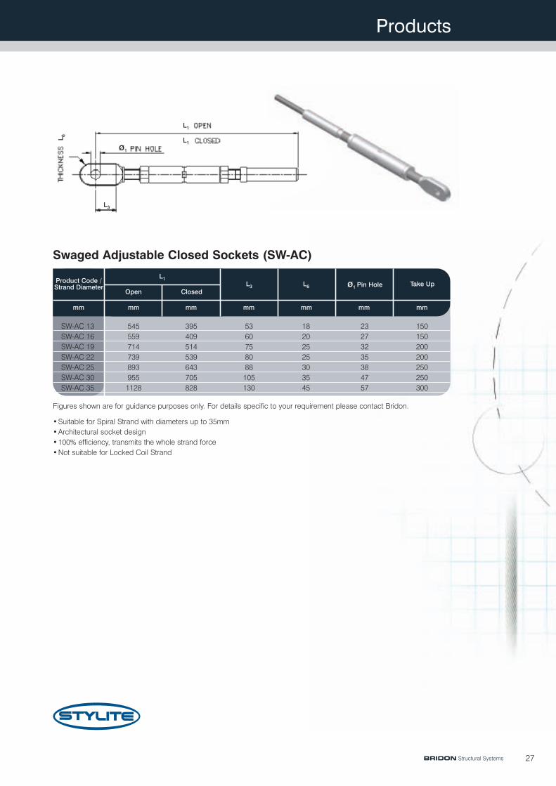
Figures shown are for guidance purposes only. For details specific to your requirement please contact Bridon.
•Suitable for Spiral Strand with diameters up to 35mm•Architectural socket design•100% efficiency, transmits the whole strand force•Not suitable for Locked Coil Strand
Swaged Adjustable Closed Sockets (SW-AC)
Product Code /Strand Diameter
mm mm mm mm mm mmmm
L1
Open ClosedL3 L6 ø1 Pin Hole Take Up
SW-AC 13SW-AC 16SW-AC 19SW-AC 22SW-AC 25SW-AC 30SW-AC 35
5455597147398939551128
395409514539643705828
5360758088105130
18202525303545
23273235384757
150150200200250250300
BRIDON Structural Systems
L1
L1
L3
L 6
ø1

Products
28
Figures shown are for guidance purposes only. For details specific to your requirement please contact Bridon.
•Suitable for Spiral Strand with diameters up to 35mm•Architectural socket design•100% efficiency, transmits the whole strand force•Not suitable for Locked Coil Strand
Product Code /Strand Diameter
Metricmmmmmmmmmm
L1 L2 L3 ø1 Thread Size
SW-S 13 138 263 135 30 M27 x 3SW-S 16 170 309 135 37 M30 x 3.5SW-S 19 203 373 175 40 M36 x 4SW-S 22 227 407 180 46 M39 x 4SW-S 25 262 457 225 52 M48 x 5SW-S 30 302 537 245 65 M56 x 5.5SW-S 35 336 621 285 72 M64 x 6
Swaged Stud Socket (SW-S)
BRIDON Structural Systems
L1
L2
L3
ø 1
Products
29
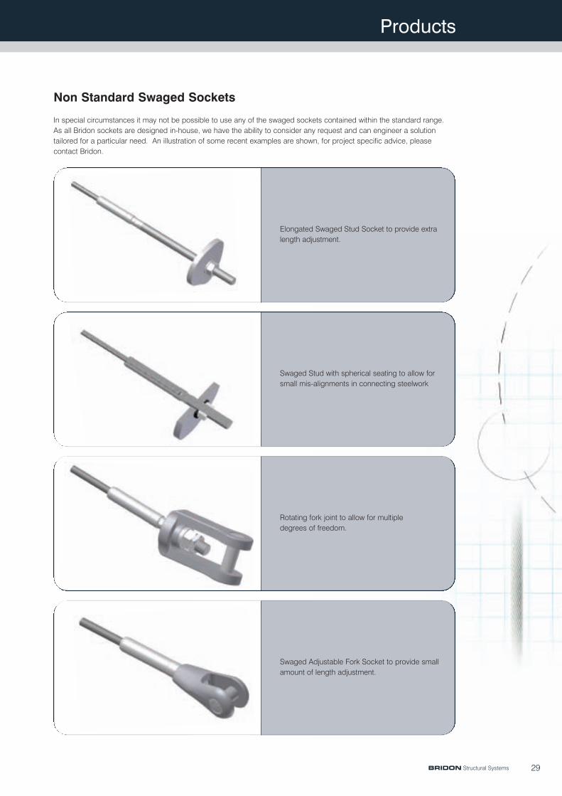
Elongated Swaged Stud Socket to provide extralength adjustment.
Swaged Stud with spherical seating to allow forsmall mis-alignments in connecting steelwork
Rotating fork joint to allow for multipledegrees of freedom.
Swaged Adjustable Fork Socket to provide smallamount of length adjustment.
Non Standard Swaged Sockets
In special circumstances it may not be possible to use any of the swaged sockets contained within the standard range.As all Bridon sockets are designed in-house, we have the ability to consider any request and can engineer a solutiontailored for a particular need. An illustration of some recent examples are shown, for project specific advice, pleasecontact Bridon.
BRIDON Structural Systems
Technical Information
30
Bridon’s aim is to assist with your project from the initialconcept through the detailed design and ultimateconstruction. To achieve this aim, certain technicalinformation is pre-requisite.
Bridon manufactures in accordance with all majorinternational standards and combines them with a series ofproven in house procedures and specifications. For specifictechnical advice, please refer to Bridon.
Planning
Bridon manufacture the widest range of cable products forthe structural market and therefore are able to offer anunbiased assessment of which particular system is mostsuited to each application. Bridon are able to assist with thefollowing:
• Feasibility studies, including cost estimates• Technical information• Maintenance advice• Steelwork interface details• Installation schemes• Buildabilty• Long term performance
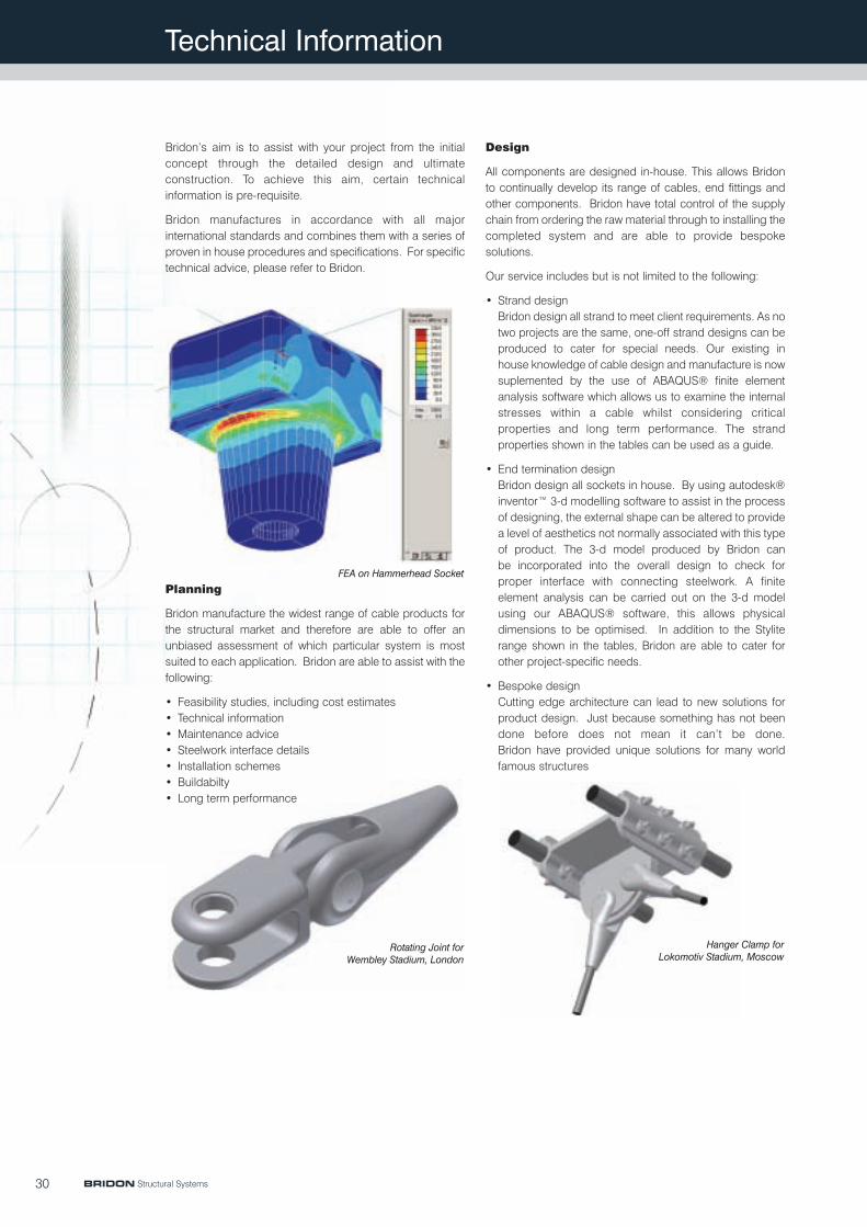
Design
All components are designed in-house. This allows Bridonto continually develop its range of cables, end fittings andother components. Bridon have total control of the supplychain from ordering the raw material through to installing thecompleted system and are able to provide bespokesolutions.
Our service includes but is not limited to the following:
• Strand designBridon design all strand to meet client requirements. As notwo projects are the same, one-off strand designs can beproduced to cater for special needs. Our existing inhouse knowledge of cable design and manufacture is nowsuplemented by the use of ABAQUS® finite elementanalysis software which allows us to examine the internalstresses within a cable whilst considering criticalproperties and long term performance. The strandproperties shown in the tables can be used as a guide.
• End termination designBridon design all sockets in house. By using autodesk®inventor™ 3-d modelling software to assist in the processof designing, the external shape can be altered to providea level of aesthetics not normally associated with this typeof product. The 3-d model produced by Bridon canbe incorporated into the overall design to check forproper interface with connecting steelwork. A finiteelement analysis can be carried out on the 3-d modelusing our ABAQUS® software, this allows physicaldimensions to be optimised. In addition to the Styliterange shown in the tables, Bridon are able to cater forother project-specific needs.
• Bespoke designCutting edge architecture can lead to new solutions forproduct design. Just because something has not beendone before does not mean it can’t be done.Bridon have provided unique solutions for many worldfamous structures
FEA on Hammerhead Socket
Rotating Joint forWembley Stadium, London
Hanger Clamp forLokomotiv Stadium, Moscow
BRIDON Structural Systems
Technical Information
31
Knowledge
Bridon are continually enhancing the product range to meetthe demands of modern structural requirements. In additionto using the latest design tools, we also have the benefit ofdecades of experience in the manufacture and testing ofcable systems. Our large database of past test results canbe used to estimate long term properties such as creep,coefficient of friction, claming forces, minimum bendingdiameters, fatigue, etc. For example, our large database oftension-tension fatigue test results allows us to deriveproduct specific S-N curves.
Use of this knowledge bank can eliminate the need to carryout certain tests up-front, providing designers with a degreeof confidence in the performance of materials integral totheir design and also removes the need for contractors tocarry out expensive product testing.
Corrosion Protection of Strand
The corrosion protection of structural strand is of paramountimportance. In order to ensure the optimum corrosion protectionsystem a series of measures and options can be selected.
These can be categorised into the following five main stages:
Stage 1 – Individual Wires
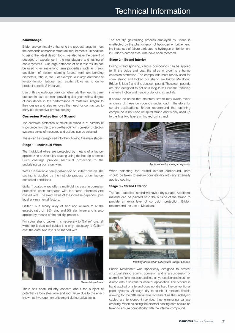
The individual wires are protected by means of a factoryapplied zinc or zinc alloy coating using the hot dip process.Such coatings provide sacrificial protection to theunderlying carbon steel wire.
Wires are available heavy galvanised or Galfan® coated. Thecoating is applied by the hot dip process under factorycontrolled conditions.
Galfan® coated wires offer a multifold increase in corrosionprotection when compared with the same thickness zinccoated wire. The exact value of the increase depends uponlocal environmental factors.
Galfan® is a binary alloy of zinc and aluminium at theeutectic ratio of 95% zinc and 5% aluminium and is alsoapplied by means of the hot dip process.
For spiral strand cables it is necessary to Galfan® coat allwires, for locked coil cables it is only necessary to Galfan®
coat the outer two layers of shaped wire.
There has been industry concern about the subject ofpotential carbon steel wire and rod failure due to the effectknown as hydrogen embrittlement during galvanising.
The hot dip galvanising process employed by Bridon isunaffected by the phenomenon of hydrogen embrittlement.No instances of failure attributed to hydrogen embrittlementin Bridon’s carbon steel wire have been recorded.
Stage 2 – Strand Interior
During strand spinning, various compounds can be appliedto fill the voids and coat the wires in order to enhancecorrosion protection. The compounds most readily used forspiral strand and locked coil strand are Bridon Metalcoat,Bridon Brilube 2 and zinc dust compound. These compoundsare also designed to act as a long-term lubricant, reducinginter-wire friction and hence prolonging strand-life.
It should be noted that structural strand may exude minoramounts of these compounds under load. Therefore forcertain applications, Bridon recommend that spinningcompound is not used on spiral strand and is only used upto the final two layers on locked coil strand.
When selecting the strand interior compound, careshould be taken to ensure compatibility with any externallyapplied coating.
Stage 3 – Strand Exterior
The “as – supplied” strand will have a dry surface. Additionalmaterial can be painted onto the outside of the strand toprovide an extra level of corrosion protection. Bridonrecommend the use of Metalcoat.
Bridon Metalcoat® was specifically designed to protectstructural strand against corrosion and is a suspension ofaluminium flake incorporated into a hydrocarbon resin carrier,diluted with a solvent for ease of application. The product ishand applied on site and does not dry hard like conventionalpaint systems. Although dry to touch, it remains flexibleallowing for the differential wire movement as the underlyingcables are tensioned in-service, thus eliminating surfacecracking. When selecting the external coating care should betaken to ensure compatibility with the internal compound.
Galvanising of wire
Application of spinning compound
Painting of strand on Millennium Bridge, London
BRIDON Structural Systems

Technical Information
Stage 4 – Structural Design
Preventing localised corrosion points within the strandsystem can be addressed during the design phase.For example, items such as saddles and clamps mustbe designed to prevent build-up of moisture.Bridon is pleased to offer advice on this highly projectspecific subject.
Stage 5 – Planned Maintenance Programme
The success of any corrosion protection system dependson the routine maintenance it receives after installation.
When Bridon Metalcoat® is used on the strand exterior wewould recommend the following planned maintenanceprogramme is adopted.
Subsequent inspections should be programmed for similarintervals during the structure lifespan.
This maintenance programme broadly mirrors the plannedinspection and maintenance programmes laid down formost major cable supported structures. If the aboveprogramme is adopted, we would expect the underlyingsteel wires to be unaffected by corrosion during the lifespanof the structure. The above maintenance periods are givenas indicative and are applicable for the majority ofstructures. However, they do not take into account specificinstances of mechanical damage to the strand and / or otherunique environmental hazards (e.g. chemical emissions,aggressive coastal locations etc.)
Bridon is able to provide a variety of inspection regimesspecific to structural cable systems using on-siteand laboratory, mechanical and non destructive testing(NDT) methods. Please contact us to discuss your specificproject requirements.
RecomendationsInspection Number
1 (Interim Inspection) Usually conducted within 5years of initial coating. Localisedareas of discoloration requireremoval of existing material anda “touch-up”.
2 (Major Inspection) Usually conducted within 10/15years of initial coating. Completere-coating of the strand surfaceis a likely requirement.
32
Painting of LC strand on Cable Stayed Bridge, Dusseldorf - Flehe
BRIDON Structural Systems
Corrosion Protection of Sockets and Clamps
Sockets and clamps need to have the same level ofcorrosion protection as the strand. The primary corrosionprotection of sockets and clamps is provided by applying azinc coating either using the hot-dip process or by hotmetal spraying.
The galvanising is in accordance with ISO EN 1461 with aminimum thickness of 150 microns.
As with the strand, additional protection can be obtained byfurther coating the socket with Metalcoat® if required.
It is not possible to galvanise certain components as thezinc will interfere with their proper functioning. To allow thesecomponents to function properly during their operation, thelong-term corrosion protection is applied on site after finaltensioning. This can be done by coating the exposed areaswith a compound such as Metalcoat®.

Technical Information
Strand Diameter
The common value for all design standards is the minimumbreaking load (MBL) which is the load that will always beachieved in a breaking load test. The MBL is also referred toin some design standards as the characteristic breakingload or as the nominal cable strength.
Eurocode 3 (pr EN 1993):Design of steel structures Part 1.11: Design of structures withtension components This design standard uses the partialsafety factor philosophy which is also refered to as "loadresistance factor design" (LRFD). The design resistance of acable ZR,d subjected to a static load is calculated by dividingthe MBL by the partial safety factor of 1.5*1.1=1.65. If wetake the example of a 60 mm diameter locked coil strand"LC-60" the minimum breaking load is 3600 kN, therefore thedesign resistance is ZR,d=3600 kN/1.5/1.1=2182 kN.The applied loads are also multiplied by safety factors (e.g.1.35 for dead loads and 1.50 for live loads) which can befound in the national annexes to Eurocode 3. The staticcalculation for different load combinations then gives thedesign strand tensions NR,d.
The design strand tension NR,d must be smaller than or equalto the design resistance ZR,d.
ASCE 19-96:Structural Applications of Steel Cables for BuildingsThis design standard uses the single safety factor philosophywhich is also refered to as "allowable stress design" (ASD).
The static calculation for different load combinations givesthe strand tensions which are multiplied by safety factors(2.0 or 2.2, depending on the load combination). The resultof this multiplication is required to be smaller than the MBL.
Large diameter spiral strands (d>35mm) and locked coilstrand are designed and made for each particularapplication. The diameters listed in the tables of thisbrochure are just examples and any intermediate diameterscan be manufactured. If a range of different diameters isneeded, early consultation with Bridon will lead to anoptimised solution in terms of both product and cost.
Prestretching, Measurement and Modulus
For structural design, it is sometimes important to predictexact cable length under load. This is best achieved byprestretching a cable which eliminates the constructionalstretch, leading to uniform cable characteristics, a stableelastic strand modulus (E) and improved fatigueperformance. It is also possible to calculate the cablelength using either historical data or by carrying out a test ona sample length.
Strand prestretching is conducted using a series of cyclicloadings, typically between 10% and 50% of the strandminimum breaking force. The elastic strand modulus (E) ismeasured during the final prestretching cycle.
After prestretching the load is taken to the specified markingload. The prescribed strand lengths and the position ofintermediate datum points are then marked on the strand.Additionally, an axial line is applied to the strand to highlightsocket orientation during manufacturing and on site.
The elastic strand modulus varies with different strand types.
Bridon’s prestretching facilities include a 730 metre longtrack, capable of applying loads up to 4600 kN which allowsfull prestretching of strands up to 100 mm diameter. Strandslonger than 730 metres can be prestretched in severaloperations and strands larger than 100mm diameter can beprestretched to a value lower than 50% of the minimumbreaking force.
As every project is unique, we require project specificinformation from the Engineer/Client. To ensure accuracy ofproduction, strand length and the position of intermediatedatum points at a given load and temperature are needed.
In addition to the permanent extension removed duringprestretching, long term strand creep should also beconsidered. The permanent extension of a prestretchedstrand, due to creep, will typically be about 0.15 mm/mwhen held at a constant load of 42% of calculated breakingload or 45% of minimum breaking load. This canbe accounted for by marking the strand shorterafter prestretching.
Nominal Elastic Strand ModuluskN/mm2Cable Type and Size
Spiral Strand<30 mm 175 ±1031 – 45 mm 170 ±1046 – 65 mm 165 ±1066 – 75 mm 160 ±10>76 mm 155 ±10Locked Coil StrandAll sizes 165 ±10
33BRIDON Structural Systems

Technical Information
Thermal and Elastic Expansion and Contraction
The change in length of strand produced by a change intemperature will be:
�LT = � * L0 * �Twhere� = coefficient of linear expansion (12.5 x 10⁻⁶ / K)L0 = original length of cable in metres�T = change in temperature
The elastic elongation of a strand produced by a change inload will be:
�LE = (�W * L0) / (E * A)where�W = change in loadE = elastic strand modulusA = metallic cross section
Socket Fitting
All Bridon strands are fitted with sockets inside the factory.Factory fitting ensures that this critical operation takes placein a controlled environment ensuring consistently high qualitywith no outside influences. The sockets are permanentlyattached to the strand which guarantees the integrity ismaintained during subsequent transportation to site,installation and tensioning.
There are two principle methods of terminating structuralstrand. The method employed is determined, in general, bythe diameter and construction of the strand.
For spiral strand up to approximately 35mm diameter, thepreferred method of termination is by means of a swagedsocket. The strand end is located inside the hollow sectionof the socket shank. The shank is then pressed onto thestrand using a hydraulic press and special dies. Socketsare manufactured from special quality steel which is suitablefor cold forming. Exact procedures are followed ensuringthe performance of the assembly is not reduced by theswaging process.
Following swaging, the cable assembly will develop 100% ofthe strand catalogue minimum breaking strength.
For larger diameter spiral strand and locked coil strands, thepreferred method of termination is by speltering. The strandend is opened to form a “brush”. It is positioned inside theinternal conical profile of the socket, which is then filled witheither zinc alloy or polyester resin.
The cone which is formed, provides the mechanism forload transfer between strand and socket. To ensureoptimum in-service fatigue performance, the alignment andconcentricity of socket and strand is essential. This isachieved by using specially designed equipment andprocedures. Socketing is carried out in accordancewith Bridon Company Standards. Our socketing procedurescomply with all major International Standardse.g. EN 13411–4 with additional measures included,based upon our experience.
Following the attachment of the socket, the assemblywill develop 100% of the strand catalogue minimumbreaking strength.
34
Swaging of socket
Preparation of “brush”
Filling of socket with zinc alloy
BRIDON Structural Systems
Technical Information
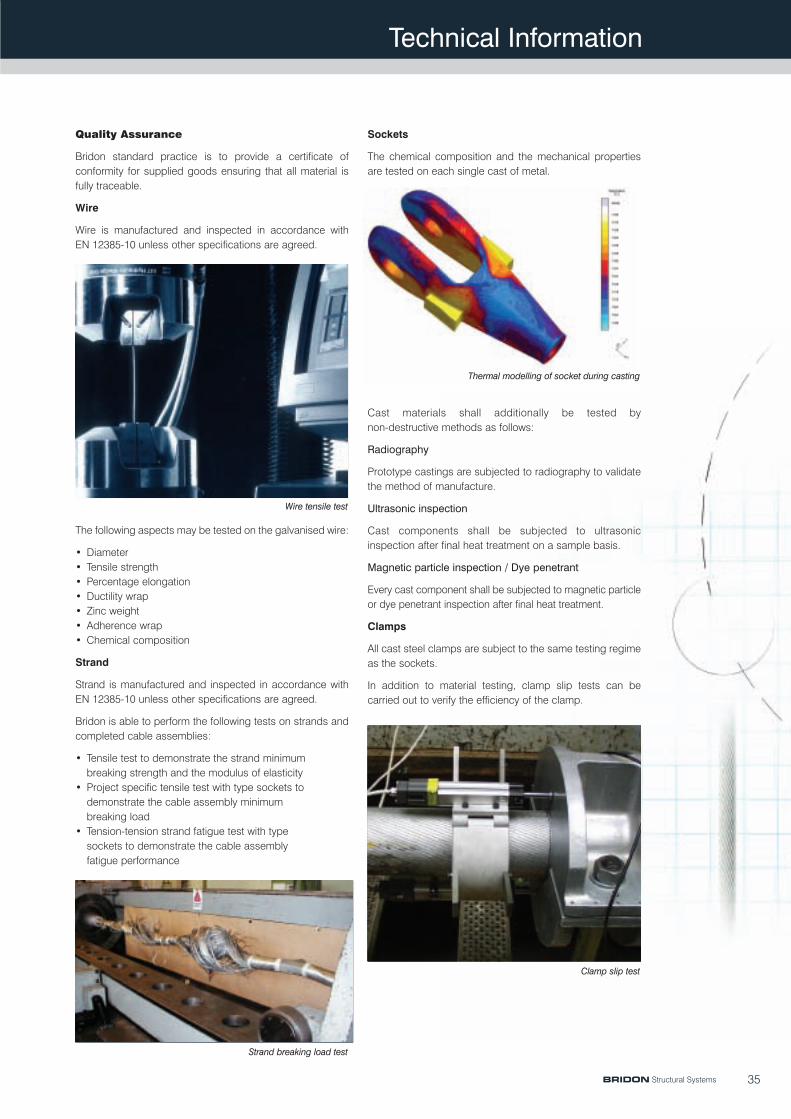
Quality Assurance
Bridon standard practice is to provide a certificate ofconformity for supplied goods ensuring that all material isfully traceable.
Wire
Wire is manufactured and inspected in accordance withEN 12385-10 unless other specifications are agreed.
The following aspects may be tested on the galvanised wire:
• Diameter• Tensile strength• Percentage elongation• Ductility wrap• Zinc weight• Adherence wrap• Chemical composition
Strand
Strand is manufactured and inspected in accordance withEN 12385-10 unless other specifications are agreed.
Bridon is able to perform the following tests on strands andcompleted cable assemblies:
• Tensile test to demonstrate the strand minimumbreaking strength and the modulus of elasticity
• Project specific tensile test with type sockets todemonstrate the cable assembly minimumbreaking load
• Tension-tension strand fatigue test with typesockets to demonstrate the cable assemblyfatigue performance
Sockets
The chemical composition and the mechanical propertiesare tested on each single cast of metal.
Cast materials shall additionally be tested bynon-destructive methods as follows:
Radiography
Prototype castings are subjected to radiography to validatethe method of manufacture.
Ultrasonic inspection
Cast components shall be subjected to ultrasonicinspection after final heat treatment on a sample basis.
Magnetic particle inspection / Dye penetrant
Every cast component shall be subjected to magnetic particleor dye penetrant inspection after final heat treatment.
Clamps
All cast steel clamps are subject to the same testing regimeas the sockets.
In addition to material testing, clamp slip tests can becarried out to verify the efficiency of the clamp.
35
Wire tensile test
Strand breaking load test
Thermal modelling of socket during casting
Clamp slip test
BRIDON Structural Systems

Technical Information
Strand Catenary Calculations
When strands are used in level or inclined spans, theshape taken by the strand is a catenary. If individual unitloads are attached between the supports as in the case ofa suspension bridge, then the strand will form a series ofcatenaries. For most practical cases where the sag tospan ratio is low, it may be assumed that the form takenby the strand is that of a parabolic arc. The followingformulae are based on this assumption.
In the case of anchored spans it is also assumed thatthere is no displacement of supports under increasedload. If displacements occur the result is larger sag.The slight error in the load calculation will result in greaterdegree of safety for the cable assembly than thatcalculated.
Where multiple loads are suspended in a span, areasonable accuracy can be obtained by assuming thesystem to be uniformly loaded, and adding the weight permetre of the applied loads to that of the strand.
For wind loads, the pressure may be taken as0.01 kg/cm2 at a wind speed of 150 km/h on the projectedarea of the cable. Under ice conditions, the radialthickness may be as high as 15 mm and the weight of ice0.9 g/cm3. Under combined wind and ice conditions, itshould be assumed that the wind is acting on thecombined ice and cable diameter, and the resulting forceshould then be found and used as the combined weightper metre.
horizontal tension t = WS2
or yc =WS2
8yc 8t
STT x
y y
yt
S/2
Level Span - Uniformly Loaded
Level Span - Single Load at Centre
STT
y
t
P
Calculation:
vertical deflection at any point in span
maximum tension T = t where tan =4yc
cos S
length of rope L = S +8yc
2
(approximately)3S
y =W x (S - x)
2t
horizontal tension t =S(2P+WS)
or yc =S(2P+WS)
8yc 8t
Calculation:
maximum tension T = t when tan = P+WScos 2t
36
0 0
0 0
Horizontal catenary
BRIDON Structural Systems

Technical Information
h = vertical difference between supports
L = length of cable in catenary
P = point load on cable
S = horizontal length of span
t = horizontal component of cable tension
T = actual cable tension
W = weight of horizontal length of uniformly distributed load
y = vertical sag measured from the chord
and � = approach angles of cable at supports
Inclined Span - Uniformly Loaded
S
T1
t
T2
hy
y
y
x
horizontal tension t = WS2
or yc =WS2
8yc 8t
Calculation:
vertical deflection at any point in span
and T1 = t when tan =4yc - h
cos S
and T2 = t when tan � =4yc + h
cos� S
length of rope L = 1 +8y2 √ S2+ h2
3S2
y =W x (S - x)
2t
horizontal tension t =S(2P+WS)
or yc =S(2P+WS)
8yc 8t
Calculation:
and T1 = t when tan = P+WS _ hcos 2t S
and T2 = t when tan � = P+WS + hcos� 2t S
( ( ))
Inclined Span - Single Load at Centre
S
T1
t
P
T2
h
37
0 0
0 0
Inclined catenary
BRIDON Structural Systems

Technical Information
Packaging and Handling
The correct packaging, transport, storage and handling ofcable assemblies is critical to ensure that the customerreceives the product in first class condition. For specificadvice on all aspects of strand lifting and handling,particularly where safety is a concern, contact Bridon.
Cable assemblies are normally supplied in coils or on reels.To avoid possible wire displacement in the strand, Bridonrecommend the following minimum coil diameters:
Locked Coil Strand 30 x strand diameter
Spiral Strand 24 x strand diameter
Coils can be wrapped in polyweave plastic to preventcontamination from foreign bodies such as dust, sand etc.It is usual for fitted sockets to protrude outside thecircumference of the coiled strand. The sockets can bewrapped to protect against mechanical damage duringtransit. Smaller diameter coils can be stacked and shrinkwrapped on enclosed wooden pallets for added protection.
Long length cable assemblies can be transported onindividually designed reels. Wooden reels are used forpiece weights up to approximately 10 tonnes, thereaftersteel reels are used. The fitted sockets are contained withinthe reel in special compartments. For additional protectionfrom contamination and damage during transit, the cablecan be wrapped in polyweave plastic and the outercircumference of the reel can be lagged with timbers.
Transport and storage guidelines
During lifting, always use a minimum of three equidistantlypositioned soft slings of sufficient length to avoid deformingthe coil. When stacking coils, either during transportation orfor storage, always use adequate wood dunnage. Reels aregenerally lifted by means of a centre shaft. For long termstorage of cables, always ensure protection fromatmospheric influences but maintain adequate ventilation toavoid the build up of condensation. Avoid direct contactwith the floor and ensure there is a flow of air under thestrand.
On site handling recommendations
Coiled strands require special care when handling and mustbe placed on a rotating braked pay-off stand. The cableassembly should then be pulled off horizontally – pulling thecable vertically will create a corkscrew effect and damagethe product. For cable assemblies supplied on reels asuitably braked stand should be used.
When handling cable assemblies we recommend thefollowing:
• Observe the cable at all times, do not allow it tokink, twist or be pulled over sharp edges
• Maintain a bend radius of at least 15 times thecable diameter for locked coil and 12 times thecable diameter for spiral strand
• Avoid damaging the zinc coating• Always remove any seizing wires after installation
38
Coil
Reel
Transport by road
Transport by air
BRIDON Structural Systems
Technical Information
Erection Engineering
Although the use of steel cable systems is becoming morecommon for a wide range of structures, the method ofconstruction is not standard. Proper planning of theconstruction requires a level of knowledge and experiencewhich is not always available within an organisation. Cablestructures are unlike other conventional buildings in manycases and special calculation methods including non-linearanalysis may be required.
Bridon are able to assist architects, engineers or designersat feasibility stage to check proposals and to advise onconstruction issues and also provide cost estimates.
During the construction phase, Bridon offer a full supply andinstallation service which allows the contractor to interactwith one party only during this critical stage. The serviceincludes co-ordination between other trades during theerection as well as checking of critical interface dimensions.
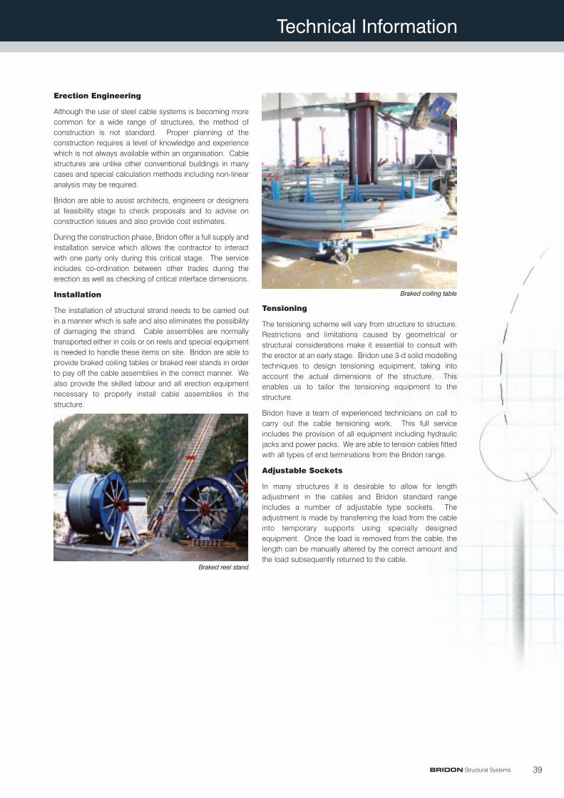
Installation
The installation of structural strand needs to be carried outin a manner which is safe and also eliminates the possibilityof damaging the strand. Cable assemblies are normallytransported either in coils or on reels and special equipmentis needed to handle these items on site. Bridon are able toprovide braked coiling tables or braked reel stands in orderto pay off the cable assemblies in the correct manner. Wealso provide the skilled labour and all erection equipmentnecessary to properly install cable assemblies in thestructure.
Braked reel stand
Braked coiling table
Tensioning
The tensioning scheme will vary from structure to structure.Restrictions and limitations caused by geometrical orstructural considerations make it essential to consult withthe erector at an early stage. Bridon use 3-d solid modellingtechniques to design tensioning equipment, taking intoaccount the actual dimensions of the structure. Thisenables us to tailor the tensioning equipment to thestructure.
Bridon have a team of experienced technicians on call tocarry out the cable tensioning work. This full serviceincludes the provision of all equipment including hydraulicjacks and power packs. We are able to tension cables fittedwith all types of end terminations from the Bridon range.
Adjustable Sockets
In many structures it is desirable to allow for lengthadjustment in the cables and Bridon standard rangeincludes a number of adjustable type sockets. Theadjustment is made by transferring the load from the cableinto temporary supports using specially designedequipment. Once the load is removed from the cable, thelength can be manually altered by the correct amount andthe load subsequently returned to the cable.
39BRIDON Structural Systems
Technical Information
40
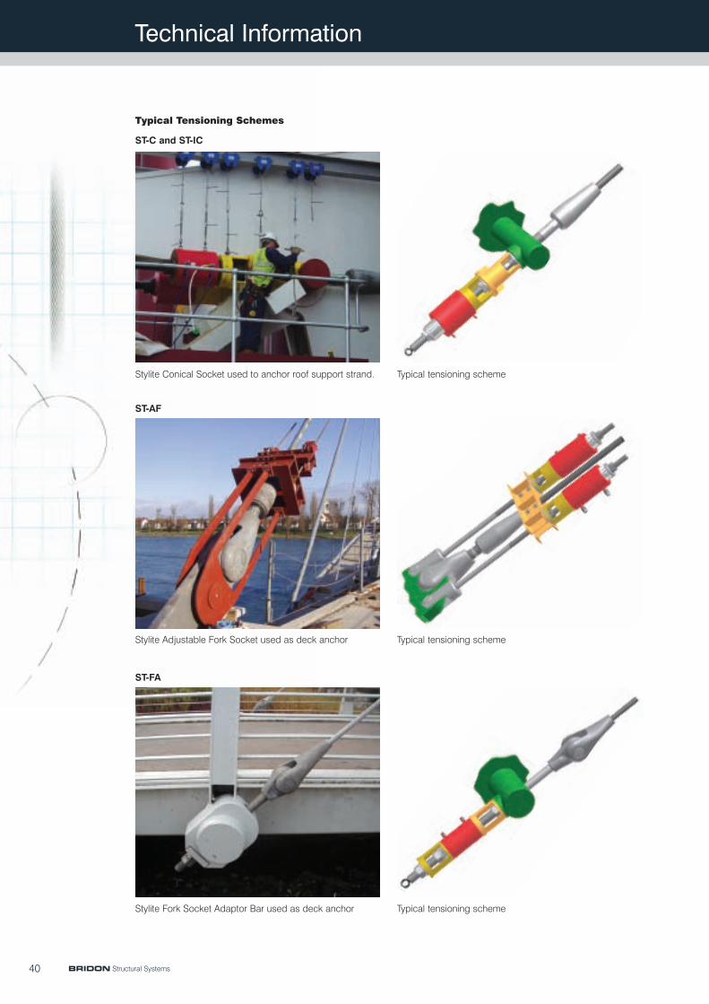
Typical Tensioning Schemes
ST-C and ST-IC
Stylite Conical Socket used to anchor roof support strand. Typical tensioning scheme
ST-AF
Stylite Adjustable Fork Socket used as deck anchor Typical tensioning scheme
ST-FA
Stylite Fork Socket Adaptor Bar used as deck anchor Typical tensioning scheme
BRIDON Structural Systems

Technical Information
41
ST-B
Stylite Block Socket used as main cable anchor Typical tensioning scheme
ST-IEC
Stylite Internal/External Thread Cylindrical Socket used toanchor roof catenary strand
Typical tensioning scheme
ST-IEC
Stylite Internal/External Socket with spherical seating Typical tensioning scheme (with spherical seating)
BRIDON Structural Systems
Technical Information
42
Cable Inspection
The use of spiral strand and locked coil strand allows foreasy inspection during service. The most basic form ofinspection is a visual examination of the strand and socket.This can be carried out manually or automatically usingremote cameras. Any external corrosion or broken wirescan be identified and remedial action carried out.
Main Cable inspection on Tamar Bridge, UK
Actual prestress force in a structure using spiral strand orlocked coil strand can also be measured easily using anumber of methods.
Strand tension measurement
It is also possible to check the internal condition of thestrand. This is usually carried out using NDT techniques.Examples of this include wire break detection using acousticmonitoring and internal corrosion detection using electro-magnetism.
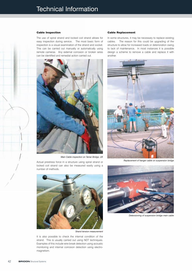
Cable Replacement
In some structures, it may be necessary to replace existingcables. The reason for this could be upgrading of thestructure to allow for increased loads or deterioration owingto lack of maintenance. In most instances it is possibledesign a scheme to remove a cable and replace it withanother.
Replacement of hanger cable on suspension bridge
Detensioning of suspension bridge main cable
BRIDON Structural Systems