contents how to read this design guide introduction to fc 300
TRANSCRIPT

Contents
How to Read this Design Guide 5
How to Read this Design Guide 5
Approvals 5
Symbols 6
Abbreviations 6
Definitions 7
Introduction to FC 300 13
Disposal Instruction 13
Software Version 13
Air Humidity 15
Aggressive Environments 15
Vibration and Shock 16
Control Principle 17
FC 300 Controls 17
FC 301 vs. FC 302 Control Principle 17
Control Structure in VVCplus 18
Control Structure in Flux Sensorless (FC 302 only) 19
Control Structure in Flux with Motor Feedback 19
Internal Current Control in VVC+ Mode 20
Local (Hand On) and Remote (Auto On) Control 21
Reference Handling 23
Scaling of References and Feedback 24
Dead Band Around Zero 24
Speed PID Control 29
The following parameters are relevant for the Speed Control 29
Process PID Control 31
Ziegler Nichols Tuning Method 35
EMC Test Results (Emission, Immunity) 37
EMC Immunity 38
Earth Leakage Current 40
Selection of Brake Resistor 40
Control of Mechanical Brake 42
Safe Stop of FC 300 45
Safe Stop Installation (FC 302 and FC 301 - A1 enclosure only) 46
Safe Stop Commissioning Test 47
FC 300 Selection 49
Electrical Data 49
General Specifications 53
Efficiency 58
Acoustic Noise 58
Peak Voltage on Motor 59
Derating for Installing Long Motor Cables or Cables with Larger Cross-Sec-tion 60
FC 300 Design Guide
MG.33.B7.02 - VLT is a registered Danfoss trademark 1

How to Order 63
Drive Configurator 63
Ordering Form Type Code 63
Ordering Numbers 65
How to Install 71
Mechanical Dimension 71
Mechanical Installation 73
Accessory Bag 73
Electrical Installation 76
Removal of Knockouts for Extra Cables 76
Connection to Mains and Earthing 77
Motor Connection 79
Fuses 81
Access to Control Terminals 83
Control Terminals (FC 301) 83
Electrical Installation , Control Terminals 84
Basic Wiring Example 84
Electrical Installation , Control Cables 85
Motor Cables 86
Switches S201, S202, and S801 87
Final Set-Up and Test 88
Additional Connections 90
Relay Connection 91
Relay Output 92
Parallel Connection of Motors 92
Motor Thermal Protection 93
How to Connect a PC to the FC 300 94
The FC 300 Software Dialog 94
Residual Current Device 99
Application Examples 101
Start/Stop 101
Pulse Start/Stop 101
Potentiometer Reference 102
Encoder Connection 102
Encoder Direction 102
Closed Loop Drive System 103
Programming of Torque Limit and Stop 103
Smart Logic Control Programming 104
How to Programme 107
The Graphical and Numerical Local Control Panels 107
How to Programme on the Graphical Local Control Panel 107
The LCD-Display 108
Quick Transfer of Parameter Settings 110
Display Mode 111
FC 300 Design Guide
2 MG.33.B7.02 - VLT is a registered Danfoss trademark

Display Mode - Selection of Read-Outs 111
Parameter Set-Up 112
Quick Menu Key Functions 112
Main Menu Mode 115
Parameter Selection 115
Changing Data 115
Changing a Text Value 116
Changing a Group of Numeric Data Values 116
Infinitely Variable Change of Numeric Data Value 116
Changing of Data Value , Step-by-Step 117
Read-out and Programming of Indexed Parameters 117
How to Programme on the Numerical Local Control Panel 118
Local Control Keys 119
Initialisation to Default Settings 120
Parameter Selection - FC 300 121
Parameters: Operation and Display 122
Parameters: Load and Motor 132
Parameters: Brakes 146
Parameters: Reference/Ramps 150
Parameters: Limits/Warnings 160
Parameters: Digital In/Out 165
Parameters: Analog In/Out 178
Parameters: Controllers 184
Parameters: Communications and Options 188
Parameters: Profibus 194
Parameters: DeviceNet CAN Fieldbus 200
Parameters: Smart Logic Control 205
Parameters: Special Functions 217
Parameters: Drive Information 223
Parameters: Data Read-outs 229
Parameters: EncoderInput 236
Parameter Lists 239
Options and Accessories 261
Options and Accessories 261
Mounting of Option Modules in Slot B 261
General Purpose Input Output Module MCB 101 261
Encoder Option MCB 102 263
Resolver Option MCB 103 265
Relay Option MCB 105 267
24 V Back-Up Option MCB 107 (Option D) 270
IP 21/IP 4X/ TYPE 1 Enclosure Kit 271
LC Filters 271
RS-485 Installation and Set-up 273
RS-485 Installation and Set-up 273
FC Protocol Overview 276
Network Configuration 276
FC 300 Design Guide
MG.33.B7.02 - VLT is a registered Danfoss trademark 3

FC Protocol Message Framing Structure - FC 300 277
Examples 282
Danfoss FC Control Profile 282
Troubleshooting 293
Status messages - FC 300 DG 293
Index 300
FC 300 Design Guide
4 MG.33.B7.02 - VLT is a registered Danfoss trademark

How to Read this Design Guide
How to Read this Design Guide
This Design Guide will introduce all aspects of your FC 300.
Available literature for FC 300
- The VLT® AutomationDrive FC 300 Operating Instructions MG.33.AX.YY provide the neccessaryinformation for getting the drive up and running.
- The VLT® AutomationDrive FC 300 Design Guide MG.33.BX.YY entails all technical informationabout the drive and customer design and applications.
- The VLT® AutomationDrive FC 300 Profibus Operating Instructions MG.33.CX.YY provide the in-formation required for controlling, monitoring and programming the drive via a Profibus fieldbus.
- The VLT® AutomationDrive FC 300 DeviceNet Operating Instructions MG.33.DX.YY provide theinformation required for controlling, monitoring and programming the drive via a DeviceNetfieldbus.
X = Revision numberYY = Language code
Danfoss Drives technical literature is also available online at www.danfoss.com/BusinessAreas/Drives-Solutions/Documentations/Technical+Documentation.
Approvals
FC 300 Design Guide
MG.33.B7.02 - VLT is a registered Danfoss trademark 5

Symbols
Symbols used in this Design Guide.
NB!Indicates something to be noted by the reader.
Indicates a general warning .
Indicates a high-voltage warning.
* Indicates default setting
Abbreviations Alternating current ACAmerican wire gauge AWGAmpere/AMP AAutomatic Motor Adaptation AMACurrent limit ILIM
Degrees Celcius °CDirect current DCDrive Dependent D-TYPEElectro Magnetic Compellability EMCElectronic ThermAL Relay ETRFrequency Converter FCGram gHertz HzKilohertz kHzLocal Control Panel LCPMeter mMilli Henry Inductance mHMilliampere mAMillisecond msMinute minMotion Control Tool MCTMotor Type Dependent M-TYPENanofarad nFNewton Meters NmNominal motor current IM,N
Nominal motor frequency fM,N
Nominal motor power PM,N
Nominal motor voltage UM,N
Parameter par.Protective Extra Low Voltage PELVPrinted Circuit Board PCBRated Inverter Output Current IINV
Revolutions Per Minute RPMSecond sTorque limit TLIM
Volts V
FC 300 Design Guide How to Read this Design Guide
6 MG.33.B7.02 - VLT is a registered Danfoss trademark

Definitions
Drive:
D-TYPESize and type of the connected drive (dependencies).
IVLT,MAX
The maximum output current.
IVLT,N
The rated output current supplied by the frequency converter.
UVLT, MAX
The maximum output voltage.
Input:
Control commandYou can start and stop the connected motor bymeans of LCP and the digital inputs.Functions are divided into two groups.
Functions in group 1 have higher priority thanfunctions in group 2.
Group 1 Reset, Coasting stop, Reset andCoasting stop, Quick-stop, DCbraking, Stop and the "Off" key.
Group 2 Start, Pulse start, Reversing,Start reversing, Jog and Freezeoutput
Motor:
fJOG
The motor frequency when the jog function is activated (via digital terminals).
fMThe motor frequency.
fMAX
The maximum motor frequency.
fMIN
The minimum motor frequency.
fM,N
The rated motor frequency (nameplate data).
IM
The motor current.
IM,N
The rated motor current (nameplate data).
M-TYPESize and type of the connected motor (dependencies).
nM,N
The rated motor speed (nameplate data).
PM,N
The rated motor power (nameplate data).
TM,N
The rated torque (motor).
UM
The instantaneous motor voltage.
FC 300 Design Guide How to Read this Design Guide
MG.33.B7.02 - VLT is a registered Danfoss trademark 7

UM,N
The rated motor voltage (nameplate data).
Break-away torque
ηVLT
The efficiency of the frequency converter is defined as the ratio between the power output and the powerinput.
Start-disable commandA stop command belonging to the group 1 control commands - see this group.
Stop commandSee Control commands.
References:Analog ReferenceA signal transmitted to the analog input s 53 or 54, can be voltage or current.Binary ReferenceA signal transmitted to the serial communication port.Preset ReferenceA defined preset reference to be set from -100% to +100% of the reference range. Selection of eightpreset references via the digital terminals.
Pulse ReferenceA pulse frequency signal transmitted to the digital inputs (terminal 29 or 33).
RefMAX
Determines the relationship between the reference input at 100% full scale value (typically 10 V, 20mA)and the resulting reference. The maximum reference value set in par. 3-03.
RefMIN
Determines the relationship between the reference input at 0% value (typically 0V, 0mA, 4mA) and theresulting reference. The minimum reference value set in par. 3-02.
Miscellaneous:
Analog InputsThe analog inputs are used for controlling various functions of the frequency converter.There are two types of analog inputs:Current input, 0-20 mA and 4-20 mAVoltage input, 0-10 V DC (FC 301)Voltage input, -10 - +10 V DC (FC 302).
Analog OutputsThe analog outputs can supply a signal of 0-20 mA, 4-20 mA, or a digital signal.
FC 300 Design Guide How to Read this Design Guide
8 MG.33.B7.02 - VLT is a registered Danfoss trademark
Automatic Motor Adaptation, AMAAMA algorithm determines the electrical parameters for the connected motor at standstill.
Brake ResistorThe brake resistor is a module capable of absorbing the brake power generated in regenerative braking.This regenerative braking power increases the intermediate circuit voltage and a brake chopper ensuresthat the power is transmitted to the brake resistor.
CT CharacteristicsConstant torque characteristics used for all applications such as conveyor belts, displacement pumps andcranes.
Digital InputsThe digital inputs can be used for controlling various functions of the frequency converter.
Digital OutputsThe drive features two Solid State outputs that can supply a 24 V DC (max. 40 mA) signal.
DSPDigital Signal Processor.
ETRElectronic Thermal Relay is a thermal load calculation based on present load and time. Its purpose is toestimate the motor temperature.
Hiperface®
Hiperface® is a registered trademark by Stegmann.
InitialisingIf initialising is carried out (par. 14-22), the frequency converter returns to the default setting.
Intermittent Duty CycleAn intermittent duty rating refers to a sequence of duty cycles. Each cycle consists of an on-load and anoff-load period. The operation can be either periodic duty or none-periodic duty.
LCPThe Local Control Panel (LCP) makes up a complete interface for control and programming of the FC 300Series. The control panel is detachable and can be installed up to 3 metres from the frequency converter,i.e. in a front panel by means of the installation kit option.
lsbLeast significant bit.
msbMost significant bit.
MCM
Short for Mille Circular Mil, an American measuring unit for cable cross-section. 1 MCM = 0.5067 mm2.
On-line/Off-line ParametersChanges to on-line parameters are activated immediately after the data value is changed. Changes tooff-line parameters are not activated until you enter [OK] on the LCP.
Process PIDThe PID regulator maintains the desired speed, pressure, temperature, etc. by adjusting the output fre-quency to match the varying load.
FC 300 Design Guide How to Read this Design Guide
MG.33.B7.02 - VLT is a registered Danfoss trademark 9

Pulse Input/Incremental EncoderAn external, digital pulse transmitter used for feeding back information on motor speed. The encoder isused in applications where great accuracy in speed control is required.
RCDResidual Current Device.
Set-upYou can save parameter settings in four Set-ups. Change between the four parameter Set-ups and editone Set-up, while another Set-up is active.
SFAVMSwitching pattern called Stator Flux oriented Asynchronous Vector Modulation (par. 14-00).
Slip CompensationThe frequency converter compensates for the motor slip by giving the frequency a supplement that fol-lows the measured motor load keeping the motor speed almost constant..
Smart Logic Control (SLC)The SLC is a sequence of user defined actions executed when the associated user defined events areevaluated as true by the SLC. (Parameter group 13-xx).
Thermistor :A temperature-dependent resistor placed where the temperature is to be monitored (frequency converteror motor).
TripA state entered in fault situations, e.g. if the frequency converter is subject to an over-temperature orwhen the frequency converter is protecting the motor, process or mechanism. Restart is prevented untilthe cause of the fault has disappeared and the trip state is cancelled by activating reset or, in some cases,by being programmed to reset automatically. Trip may not be used for personal safety.
Trip LockedA state entered in fault situations when the frequency converter is protecting itself and requiring physicalintervention, e.g. if the frequency converter is subject to a short circuit on the output. A locked trip canonly be cancelled by cutting off mains, removing the cause of the fault, and reconnecting the frequencyconverter. Restart is prevented until the trip state is cancelled by activating reset or, in some cases, bybeing programmed to reset automatically. Trip may not be used for personal safety.
VT CharacteristicsVariable torque characteristics used for pumps and fans.
VVCplus
If compared with standard voltage/frequency ratio control, Voltage Vector Control (VVCplus) improves thedynamics and the stability, both when the speed reference is changed and in relation to the load torque.
60° AVMSwitching pattern called 60°Asynchronous Vector Modulation (par. 14-00).
Power FactorThe power factor is the relation between I1 andIRMS.
Power factor = 3 x U x I1 x cosϕ3 x U x IRMS
The power factor for 3-phase control:= I1 x cosϕ1
IRMS=
I1IRMS
since cosϕ1 = 1
The power factor indicates to which extent thefrequency converter imposes a load on the mainssupply .
The lower the power factor, the higher the IRMS forthe same kW performance.
FC 300 Design Guide How to Read this Design Guide
10 MG.33.B7.02 - VLT is a registered Danfoss trademark

IRMS = I12 + I5
2 + I72 + .. + In
2
In addition, a high power factor indicates that the different harmonic currents are low.The FC 300 frequency converters' built-in DC coils produce a high power factor, which minimizes theimposed load on the mains supply.
FC 300 Design Guide How to Read this Design Guide
MG.33.B7.02 - VLT is a registered Danfoss trademark 11

FC 300 Design Guide
12 MG.33.B7.02 - VLT is a registered Danfoss trademark

Introduction to FC 300
Disposal Instruction
Equipment containing electrical components may not be disposed togetherwith domestic waste.It must be separate collected with Electrical and Electronic waste accordingto local and currently valid legislation.
CautionThe FC 300 AutomationDrive DC link capacitors remain charged after power has been disconnected.To avoid an electrical shock hazard, disconnect the FC 300 from the mains before carrying out main-tenance. Wait at least as follows before doing service on the frequency converter:FC 300: 0.25 7.5 kW 4 minutesFC 300: 11 22 kW 15 minutes
FC 300Design Guide
Software version: 4.0x
This Design Guide can be used for all FC 300 frequency converters with software version 4.0x.The software version number can be seen from parameter 15-43.
FC 300 Design Guide Introduction to FC 300
MG.33.B7.02 - VLT is a registered Danfoss trademark 13
CE Conformity and Labelling
What is CE Conformity and Labelling?The purpose of CE labelling is to avoid technical trade obstacles within EFTA and the EU. The EU hasintroduced the CE label as a simple way of showing whether a product complies with the relevant EUdirectives. The CE label says nothing about the specifications or quality of the product. Frequency con-verters are regulated by three EU directives:The machinery directive (98/37/EEC)All machines with critical moving parts are covered by the machinery directive of January 1, 1995. Sincea frequency converter is largely electrical, it does not fall under the machinery directive. However, if afrequency converter is supplied for use in a machine, we provide information on safety aspects relatingto the frequency converter. We do this by means of a manufacturer's declaration.The low-voltage directive (73/23/EEC)Frequency converters must be CE labelled in accordance with the low-voltage directive of January 1,1997. The directive applies to all electrical equipment and appliances used in the 50 - 1000 V AC and the75 - 1500 V DC voltage ranges. Danfoss CE-labels in accordance with the directive and issues a decla-ration of conformity upon request.The EMC directive (89/336/EEC)EMC is short for electromagnetic compatibility. The presence of electromagnetic compatibility means thatthe mutual interference between different components/appliances does not affect the way the applianceswork.The EMC directive came into effect January 1, 1996. Danfoss CE-labels in accordance with the directiveand issues a declaration of conformity upon request. To carry out EMC-correct installation, see the in-structions in this Design Guide. In addition, we specify which standards our products comply with. Weoffer the filters presented in the specifications and provide other types of assistance to ensure the opti-mum EMC result.
The frequency converter is most often used by professionals of the trade as a complex component formingpart of a larger appliance, system or installation. It must be noted that the responsibility for the final EMCproperties of the appliance, system or installation rests with the installer.
What Is Covered
The EU "Guidelines on the Application of Council Directive 89/336/EEC" outline three typical situations ofusing a frequency converter. See below for EMC coverage and CE labelling.
1. The frequency converter is sold directly to the end-consumer. The frequency converter is forexample sold to a DIY market. The end-consumer is a layman. He installs the frequency converterhimself for use with a hobby machine, a kitchen appliance, etc. For such applications, the fre-quency converter must be CE labelled in accordance with the EMC directive.
2. The frequency converter is sold for installation in a plant. The plant is built up by professionalsof the trade. It could be a production plant or a heating/ventilation plant designed and installedby professionals of the trade. Neither the frequency converter nor the finished plant has to be CElabelled under the EMC directive. However, the unit must comply with the basic EMC require-ments of the directive. This is ensured by using components, appliances, and systems that areCE labelled under the EMC directive.
3. The frequency converter is sold as part of a complete system. The system is being marketed ascomplete and could e.g. be an air-conditioning system. The complete system must be CE labelledin accordance with the EMC directive. The manufacturer can ensure CE labelling under the EMCdirective either by using CE labelled components or by testing the EMC of the system. If hechooses to use only CE labelled components, he does not have to test the entire system.
FC 300 Design Guide Introduction to FC 300
14 MG.33.B7.02 - VLT is a registered Danfoss trademark

Danfoss VLT Frequency Converter and CELabelling
CE labelling is a positive feature when used for its original purpose, i.e. to facilitate trade within the EUand EFTA.
However, CE labelling may cover many different specifications. Thus, you have to check what a given CElabel specifically covers.
The covered specifications can be very different and a CE label may therefore give the installer a falsefeeling of security when using a frequency converter as a component in a system or an appliance.
Danfoss CE labels the frequency converters in accordance with the low-voltage directive. This means thatif the frequency converter is installed correctly, we guarantee compliance with the low-voltage directive.Danfoss issues a declaration of conformity that confirms our CE labelling in accordance with the low-voltage directive.
The CE label also applies to the EMC directive provided that the instructions for EMC-correct installationand filtering are followed. On this basis, a declaration of conformity in accordance with the EMC directiveis issued.
The Design Guide offers detailed instructions for installation to ensure EMC-correct installation. Further-more, Danfoss specifies which our different products comply with.
Danfoss gladly provides other types of assistance that can help you obtain the best EMC result.
Compliance with EMC Directive 89/336/EEC
As mentioned, the frequency converter is mostly used by professionals of the trade as a complex com-ponent forming part of a larger appliance, system, or installation. It must be noted that the responsibilityfor the final EMC properties of the appliance, system or installation rests with the installer. As an aid tothe installer, Danfoss has prepared EMC installation guidelines for the Power Drive system. The standardsand test levels stated for Power Drive systems are complied with, provided that the EMC-correct instruc-tions for installation are followed, see section Electrical Installation.
Air Humidity
The frequency converter has been designed to meet the IEC/EN 60068-2-3 standard, EN 50178 pkt.9.4.2.2 at 50°C.
Aggressive Environments
A frequency converter contains a large number of mechanical and electronic components. All are to someextent vulnerable to environmental effects.
The frequency converter should not be installed in environments with airborne liquids, parti-cles, or gases capable of affecting and damaging the electronic components. Failure to takethe necessary protective measures increases the risk of stoppages, thus reducing the life ofthe frequency converter.
Liquids can be carried through the air and condense in the frequency converter and may cause corrosionof components and metal parts. Steam, oil, and salt water may cause corrosion of components and metalparts. In such environments, use equipment with enclosure rating IP 55. As an extra protection , coatedprintet circuit boads can be orded as an option.
Airborne Particles such as dust may cause mechanical, electrical, or thermal failure in the frequency con-verter. A typical indicator of excessive levels of airborne particles is dust particles around the frequencyconverter fan. In very dusty environments, use equipment with enclosure rating IP 55 or a cabinet for IP00/IP 20/TYPE 1 equipment.
FC 300 Design Guide Introduction to FC 300
MG.33.B7.02 - VLT is a registered Danfoss trademark 15

In environments with high temperatures and humidity, corrosive gases such as sulphur, nitrogen, andchlorine compounds will cause chemical processes on the frequency converter components.
Such chemical reactions will rapidly affect and damage the electronic components. In such environments,mount the equipment in a cabinet with fresh air ventilation, keeping aggressive gases away from thefrequency converter.An extra protection in such areas is a coating of the printed circuit boards, which can be ordered as anoption.
NB!Mounting frequency converters in aggressive environments increases the risk of stoppagesand considerably reduces the life of the converter.
Before installing the frequency converter, check the ambient air for liquids, particles, and gases. This isdone by observing existing installations in this environment. Typical indicators of harmful airborne liquidsare water or oil on metal parts, or corrosion of metal parts.
Excessive dust particle levels are often found on installation cabinets and existing electrical installations.One indicator of aggressive airborne gases is blackening of copper rails and cable ends on existing in-stallations.
Vibration and Shock
The frequency converter has been tested accord-ing to a procedure based on the shown standards:
The frequency converter complies with require-ments that exist for units mounted on the wallsand floors of production premises, as well as inpanels bolted to walls or floors.
IEC/EN 60068-2-6: Vibration (sinusoidal) - 1970IEC/EN 60068-2-64: Vibration, broad-band ran-
dom
FC 300 Design Guide Introduction to FC 300
16 MG.33.B7.02 - VLT is a registered Danfoss trademark

Control Principle
A frequency converter rectifies AC voltage from mains into DC voltage, after which this DC voltage isconverted into a AC current with a variable amplitude and frequency.
The motor is supplied with variable voltage / current and frequency, which enables infinitely variablespeed control of three-phased, standard AC motors and permanent magnet synchronous motors.
FC 300 Controls
The frequency converter is capable of controlling either the speed or the torque on the motor shaft. Set-ting par. 1-00 determines the type of control.
Speed control:There are two types of speed control:
Speed open loop control which does not require any feedback (sensorless).
Speed closed loop control in the form of a PID control that requires a speed feedback to an input.A properly optimised speed closed loop control will have higher accuracy than a speed open loopcontrol.
Selects which input to use as speed PID feedback in par. 7-00.
Torque control (FC 302 only):Torque control is part of the motor control and correct settings of motor parameters are very important.The accuracy and settling time of the torque control are determined from Flux with motor feedback (par.1-01 Motor Control Principle).
Flux with encoder feedback offers superior performance in all four quadrants and at all motorspeeds.
Speed / torque reference:The reference to these controls can either be a single refrence or be the sum of various references in-cluding relatively scaled references. The handling of references is explained in detail later in this section.
FC 301 vs. FC 302 Control Principle
FC 301 is a general purpose frequency converter for variable speed applications. The control principle is
based on Voltage Vector Control (VVCplus).FC 301 can handle asynchronous motors only.The current sensing principle in FC 301 is based on current measurement in the DC link or motor phase.The ground fault protection on the motor side is solved by a de-saturation circuit in the IGBTs connectedto the control board.Short circuit behaviour on FC 301 depends on the current transducer in the positive DC link and thedesaturation protection with feedback from the 3 lower IGBT's and the brake.
FC 300 Design Guide Introduction to FC 300
MG.33.B7.02 - VLT is a registered Danfoss trademark 17

FC 302 is a high performance frequency converter for demanding applications. The frequency convertercan handle various kinds of motor control principles such as U/f special motor mode, VVCplus or FluxVector motor control.FC 302 is able to handle Permanent Magnet Synchronous Motors (Brushless servo motors) as well asnormal squirrel cage asynchronous motors.Short circuit behaviour on FC 302 depends on the 3 current transducers in the motor phases and thedesaturation protection with feedback from the brake.
Control Structure in VVCplus
Control structure in VVCplus open loop and closed loop configurations:
In the configuration shown in the illustration above, par. 1-01 Motor Control Principle is set to VVCplus
[1] and par. 1-00 is set to Speed open loop [0]. The resulting reference from the reference handlingsystem is received and fed through the ramp limitation and speed limitation before being sent to themotor control. The output of the motor control is then limited by the maximum frequency limit.
If par. 1-00 is set to Speed closed loop [1] the resulting reference will be passed from the ramp limi-tation and speed limitation into a speed PID control. The Speed PID control parameters are located inthe par. group 7-0*. The resulting reference from the Speed PID control is sent to the motor controllimited by the frequency limit.
FC 300 Design Guide Introduction to FC 300
18 MG.33.B7.02 - VLT is a registered Danfoss trademark

Select Process [3] in par. 1-00 to use the process PID control for closed loop control of e.g. speed orpressure in the controlled application. The Process PID parameters are located in par. group 7-2* and7-3*.
Control Structure in Flux Sensorless (FC302 only)
Control structure in Flux sensorless open loop and closed loop configurations.
In the shown configuration, par. 1-01 Motor Control Principle is set to Flux sensorless [2] and par. 1-00is set to Speed open loop [0]. The resulting reference from the reference handling system is fed throughthe ramp and speed limitations as determined by the parameter settings indicated.
An estimated speed feedback is generated to the Speed PID to control the output frequency.The Speed PID must be set with its P,I, and D parameters (par. group 7-0*).
Select Process [3] in par. 1-00 to use the process PID control for closed loop control of i.e. speed orpressure in the controlled application. The Process PID parameters are found in par. group 7-2* and 7-3*.
Control Structure in Flux with Motor Feedback
Control structure in Flux with motor feedback configuration (only available in FC 302):
FC 300 Design Guide Introduction to FC 300
MG.33.B7.02 - VLT is a registered Danfoss trademark 19

In the shown configuration, par. 1-01 Motor Control Principle is set to Flux w motor feedb [3] and par.1-00 is set to Speed closed loop [1].
The motor control in this configuration relies on a feedback signal from an encoder mounted directly onthe motor (set in par. 1-02 Motor Shaft Encoder Source).
Select Speed closed loop [1] in par. 1-00 to use the resulting reference as an input for the Speed PIDcontrol. The Speed PID control parameters are located in par. group 7-0*.
Select Torque [2] in par. 1-00 to use the resulting reference directly as a torque reference. Torquecontrol can only be selected in the Flux with motor feedback (par. 1-01 Motor Control Principle) config-uration. When this mode has been selected, the reference will use the Nm unit. It requires no torquefeedback, since the actual torque is calculated on the basis of the current measurement of the frequencyconverter.
Select Process [3] in par. 1-00 to use the process PID control for closed loop control of e.g. speed or aprocess variable in the controlled application.
Internal Current Control in VVC+ Mode
The frequency converter features an integral current limit control which is activated when the motorcurrent, and thus the torque, is higher than the torque limits set in par. 4-16, 4-17 and 4-18.When the frequency converter is at the current limit during motor operation or regenerative operation,the frequency converter will try to get below the preset torque limits as quickly as possible without losingcontrol of the motor.
FC 300 Design Guide Introduction to FC 300
20 MG.33.B7.02 - VLT is a registered Danfoss trademark
Local (Hand On) and Remote (Auto On) Con-trol
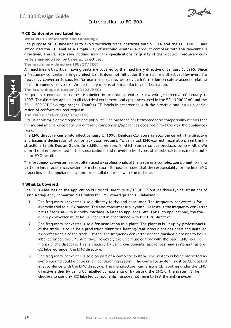
The frequency converter can be operated manually via the local control panel ( LCP ) or remotely viaanalog and digital inputs and serial bus.If allowed in par. 0-40, 0-41, 0-42, and 0-43, it is possible to start and stop the frequency converter viathe LCP using the [Hand ON] and [Off] keys. Alarms can be reset via the [RESET] key. After pressing the[Hand On] key, the frequency converter goes into Hand mode and follows (as default) the Local referencethat can be set using arrow key on the LCP.
After pressing the [Auto On] key, the frequencyconverter goes into Auto mode and follows (asdefault) the Remote reference. In this mode, it ispossible to control the frequency converter via thedigital inputs and various serial interfaces(RS-485, USB, or an optional fieldbus). See moreabout starting, stopping, changing ramps and pa-rameter set-ups etc. in par. group 5-1* (digitalinputs) or par. group 8-5* (serial communica-tion).
130BP046.10
Active Reference and Configuration Mode
The active reference can be either the local reference or the remote reference.
In par. 3-13 Reference Site the local reference can be permanently selected by selecting Local [2].To permanently select the remote reference select Remote [1]. By selecting Linked to Hand/Auto [0](default) the reference site will depend on which mode is active. (Hand Mode or Auto Mode).
Hand OnAutoLCP Keys
Reference SitePar. 3-13
Active Reference
Hand Linked to Hand / Auto LocalHand -> Off Linked to Hand / Auto LocalAuto Linked to Hand / Auto RemoteAuto -> Off Linked to Hand / Auto RemoteAll keys Local LocalAll keys Remote Remote
The table shows under which conditions either the Local reference or the Remote reference is active. Oneof them is always active, but both can not be active at the same time.
FC 300 Design Guide Introduction to FC 300
MG.33.B7.02 - VLT is a registered Danfoss trademark 21

Par. 1-00 Configuration Mode determines what kind of application control principle (i.e. Speed, Torqueor Process Control) is used when the Remote reference is active (see table above for the conditions).
Par. 1-05 Local Mode Configuration determines the kind of application control principle that is used whenthe Local reference is made activate.
Reference HandlingLocal Reference
Remote ReferenceThe reference handling system for calculating the Remote reference is shown in the illustration below.
The Remote reference is calculated once every scan interval and initially consists of two parts:
1. X (the external reference) : A sum (see par. 3-04) of up to four externally selected references,comprising any combination (determined by the setting of par. 3-15, 3-16 and 3-17) of a fixedpreset reference (par. 3-10), variable analog references, variable digital pulse references, andvarious serial bus references in whatever unit frequency converter are controlled ([Hz], [RPM],[Nm] etc.).
2. Y- (the relative reference): A sum of one fixed preset reference (par. 3-14) and one variableanalog reference (par. 3-18) in [%].
The two parts are combined in the following calculation: Remote reference = X + X * Y / 100%. The catch up / slow down function and the freeze reference function can both be activated by digital inputson the frequency converter. They are described in par. group 5-1*.The scaling of analog references are described in par. groups 6-1* and 6-2*, and the scaling of digitalpulse references are described in par. group 5-5*.Reference limits and ranges are set in par. group 3-0*.
FC 300 Design Guide Introduction to FC 300
22 MG.33.B7.02 - VLT is a registered Danfoss trademark

Reference Handling
References and feedback can be scaled in physical units (i.e. RPM, Hz, °C) or simply in % relating to thevalues of par. 3-02 Minimum Reference and par. 3-03 Maximum Reference.
In that case all analog and pulse inputs are scaled according to the following rules: When par. 3-00 Reference Range is [0] Min - Max 0% reference equals 0 [unit] where unit can
be any unit e.g. rpm, m/s, bar etc. 100% reference equals the Max (abs (par. 3-03 MaximumReference), abs (par. 3-02 Minimum Reference)).
When par. 3-00 Reference Range: [1] -Max - +Max 0% reference equals 0 [unit] -100% refer-ence equals -Max Reference 100% reference equals Max Reference.
Bus references are scaled according to the following rules: When par. 3-00 Reference Range is [0] Min - Max. To obtain max resolution on the bus reference
the scaling on the bus is: 0% reference equals Min Reference and 100% reference equals Maxreference.
When par. 3-00 Reference Range: [1] -Max - +Max -100% reference equals -Max Reference100% reference equals Max Reference.
Par. 3-00 Reference Range, 3-02 Minimum Reference and 3-03 Maximum Reference together define theallowed range of the sum of all references. The sum of all references are clamped when necessary. Therelation between the resulting reference (after clamping) and the sum of all references is shown below.
The value of par. 3-02 Minimum Reference cannot be set to less than 0, unless the par. 1-00Configuration Mode is set to [3] Process. In thatcase the following relations between the resultingreference (after clamping) and the sum of all ref-erences is as shown to the right.
FC 300 Design Guide Introduction to FC 300
MG.33.B7.02 - VLT is a registered Danfoss trademark 23
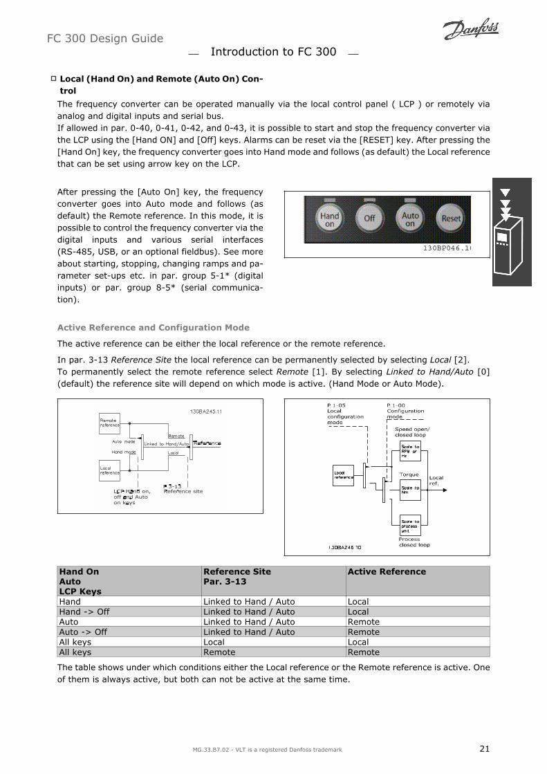
Scaling of References and Feedback
References and feedback are scaled from analog and pulse inputs in the same way. The only differenceis that a reference above or below the specified minimum and maximum endpoints (P1 and P2 in thegraph below) are clamped whereas a feedback above or below is not.
The endpoints P1 and P2 are defined by the following parameters depending on which analog or pulseinput is used
Analog 53S201=OFF
Analog 53S201=ON
Analog 54S202=OFF
Analog 54S202=ON
Pulse Input 29 Pulse Input 33
P1 = (Minimum input value, Minimum reference value)Minimum reference value Par. 6-14 Par. 6-14 Par. 6-24 Par. 6-24 Par. 5-52 Par. 5-57Minimum input value Par. 6-10 [V] Par. 6-12 [mA] Par. 6-20 [V] Par. 6-22 [mA] Par. 5-50 [Hz] Par. 5-55 [Hz]P2 = (Maximum input value, Maximum reference value)Maximum reference value Par. 6-15 Par. 6-15 Par. 6-25 Par. 6-25 Par. 5-53 Par. 5-58Maximum input value Par. 6-11 [V] Par. 6-13 [mA] Par. 6-21 [V] Par. 6-23 [mA] Par. 5-51 [Hz] Par. 5-56 [Hz]
Dead Band Around Zero
In some cases the reference (in rare cases also the feedback) should have a Dead Band around zero(i.e. to make sure the machine is stopped when the reference is near zero). To make the dead bandactive and to set the amount of dead band, the following settings must be done:
Either Minimum Reference Value (see table above for relevant parameter) or Maximum ReferenceValue must be zero. In other words; Either P1 or P2 must be on the X-axis in the graph below.
And both points defining the scaling graph are in the same quadrant.
The size of the Dead Band is defined by either P1 or P2 as shown in the graph below.
FC 300 Design Guide Introduction to FC 300
24 MG.33.B7.02 - VLT is a registered Danfoss trademark

Thus a reference endpoint of P1 = (0 V, 0 RPM) will not result in any dead band, but a reference endpointof e.g. P1 = (1V, 0 RPM) will result in a -1V to +1V dead band in this case provided that the end pointP2 is placed in either Quadrant 1 or Quadrant 4.
FC 300 Design Guide Introduction to FC 300
MG.33.B7.02 - VLT is a registered Danfoss trademark 25

Case 1: Positive Reference with Dead band, Digital input to trigger reverseThis Case shows how Reference input with limits inside Min Max limits clamps.
FC 300 Design Guide Introduction to FC 300
26 MG.33.B7.02 - VLT is a registered Danfoss trademark

Case 2: Positive Reference with Dead band, Digital input to trigger reverse. Clamping rules.This Case shows how Reference input with limits outside -Max +Max limits clamps to the inputs lowand high limits before addition to External reference. And how the External reference is clamped to -Max +Max by the Reference algorithm.
FC 300 Design Guide Introduction to FC 300
MG.33.B7.02 - VLT is a registered Danfoss trademark 27

Case 3: Negative to positive reference with dead band, Sign determines the direction, -Max +Max
FC 300 Design Guide Introduction to FC 300
28 MG.33.B7.02 - VLT is a registered Danfoss trademark

Speed PID Control
The table shows the control configurations where the Speed Control is active.
Par. 1-00 Configura-tion Mode
Par. 1-01 Motor Control PrincipleU/f VVCplus Flux Sensorless Flux w/ enc. feedb
[0] Speed open loop Not Active Not Active ACTIVE N.A.[1] Speed closed loop N.A. ACTIVE N.A. ACTIVE[2] Torque N.A. N.A. N.A. Not Active[3] Process Not Active ACTIVE ACTIVE
Note: N.A. means that the specific mode is not available at all. Not Active means that the specificmode is available but the Speed Control is not active in that mode.
Note: The Speed Control PID will work under the default parameter setting, but tuning the parametersis highly recommended to optimize the motor control performance. The two Flux motor control principlesare specially dependant on proper tuning to yield their full potential.
The following parameters are relevant for the Speed Control:
Parameter Description of functionFeedback Par. 7-00 Select from which input the Speed PID should get its feedback.Proportional Gain Par.7-02
The higher the value - the quicker the control. However, too high value maylead to oscillations.
Integral Time Par. 7-03 Eliminates steady state speed error. Lower value means quick reaction. How-ever, too low value may lead to oscillations.
Differentiation Time Par.7-04
Provides a gain proportional to the rate of change of the feedback. A settingof zero disables the differentiator.
Differentiator Gain LimitPar. 7-05
If there are quick changes in reference or feedback in a given application -which means that the error changes swiftly - the differentiator may soonbecome too dominant. This is because it reacts to changes in the error. Thequicker the error changes, the stronger the differentiator gain is. The differ-entiator gain can thus be limited to allow setting of the reasonable differen-tiation time for slow changes and a suitably quick gain for quick changes.
Lowpass Filter Time Par.7-06
A low-pass filter that dampens oscillations on the feedback signal and im-proves steady state performance. However, too large filter time will deterio-rate the dynamic performance of the Speed PID control.Practical settings of Par 7-06 taken from the number of pulses per revolutionon from encoder (PPR):Encoder PPR Par. 7-06 512 10 ms 1024 5 ms 2048 2 ms 4096 1 ms
Below is given an example of how to programme the Speed Control:
In this case the Speed PID Control is used tomaintain a constant motor speed regardless of thechanging load on the motor.
The required motor speed is set via a potentiom-eter connected to terminal 53. The speed range is0 - 1500 RPM corresponding to 0 - 10V over thepotentiometer.
Starting and stopping is controlled by a switchconnected to terminal 18.
The Speed PID monitors the actual RPM of themotor by using a 24V (HTL) incremental encoder
as feedback. The feedback sensor is an encoder(1024 pulses per. revolution) connected to termi-nals 32 and 33.
In the parameter list below it is assumed that all other parameters and switches remain at their defaultsetting.
FC 300 Design Guide Introduction to FC 300
MG.33.B7.02 - VLT is a registered Danfoss trademark 29

The following must be programmed in order shown - see explanation of settings in the section How toprogramme.
Function Par. no. Setting1) Make sure the motor runs properly. Do the following:Set the motor parameters using name plate data 1-2* As specified by motor name plateHave the VLT make an Automatic Motor Adapta-tion
1-29 [1] Enable complete AMA
2) Check the motor is running and the encoder is attached properly. Do the following:Press the Hand On LCP key. Check that themotor is running and note in which direction it isturning (henceforth referred to as the positivedirection).
Set a positive reference.
Go to par. 16-20. Turn the motor slowly in thepositive direction. It must be turned so slowly(only a few RPM) that it can be determined if thevalue in par. 16-20 is increasing or decreasing.
16-20 N.A. (read-only parameter) Note: An increasingvalue overflows at 65535 and starts again at 0.
If par. 16-20 is decreasing then change the en-coder direction in par. 5-71.
5-71 [1] Counter clockwise (if par. 16-20 is decreasing)
3) Make sure the drive limits are set to safe valuesSet acceptable limits for the references. 3-02
3-030 RPM (default)1500 RPM (default)
Check that the ramp settings are within drivecapabilities and allowed application operatingspecifications.
3-413-42
default settingdefault setting
Set acceptable limits for the motor speed andfrequency.
4-114-134-19
0 RPM (default)1500 RPM (default)60 Hz (default 132 Hz)
4) Configure the Speed Control and select the Motor Control principleActivation of Speed Control 1-00 [1] Speed closed loopSelection of Motor Control Principle 1-01 [3] Flux w motor feedb5) Configure and scale the reference to the Speed ControlSet up Analog Input 53 as a reference Source 3-15 Not necessary (default)Scale Analog Input 53 0 RPM (0 V) to 1500 RPM(10V)
6-1* Not necessary (default)
6) Configure the 24V HTL encoder signal as feedback for the Motor Control and the Speed ControlSet up digital input 32 and 33 as encoder inputs 5-14
5-15[0] No operation (default)
Choose terminal 32/33 as motor feedback 1-02 Not necessary (default)Choose terminal 32/33 as Speed PID feedback 7-00 Not necessary (default)7) Tune the Speed Control PID parametersUse the tuning guidelines when relevant or tunemanually
7-0* See the guidelines below
8) Finished!Save the parameter setting to the LCP for safekeeping
0-50 [1] All to LCP
Tuning PID Speed Control
The following tuning guidelines are relevant when using one of the Flux motor control principles in ap-plications where the load is mainly inertial (with a low amount of friction).
The value of par. 7-02 Proportional Gain is dependent on the combined inertia of the motor and load, andthe selected bandwidth can be calculated using the following formula:
Par. 7− 02 =Total inertia kgm2 x Par. 1− 25
Par. 1− 20 x 9550 x Bandwidth rad / s
Note: Par. 1-20 is the motor power in [kW] (i.e. enter 4 kW instead of 4000 W in the formula). Apractical value for the Bandwith is 20 rad/s. Check the result of the par. 7-02 calculation against thefollowing formula (not required if you are using a high resolution feedback such as a SinCos feedback):
Par. 7− 02MAXIMUM = 0.01 x 4 x Encoder Resolution x par. 7− 062 x π x Max torque ripple %
A good start value for par. 7-06 Speed Filter Time is 5 ms (lower encoder resolution calls for a higherfilter value). Typically a Max Torque Ripple of 3 % is acceptable. For incremental encoders the EncoderResolution is found in either par. 5-70 (24V HTL on standard drive) or par. 17-11 (5V TTL on MCB102Option).
FC 300 Design Guide Introduction to FC 300
30 MG.33.B7.02 - VLT is a registered Danfoss trademark

Generally the practical maximum limit of par. 7-02 is determined by the encoder resolution and thefeedback filter time but other factors in the application might limit the par. 7-02 Proportional Gain to alower value.
To minimize the overshoot, par. 7-03 Integral Time could be set to approx. 2.5 s (varies with the appli-cation).
Par. 7-04 Differential Time should be set to 0 until everything else is tuned. If necessary finish the tuningby experimenting with small increments of this setting.
Process PID Control
The Process PID Control can be used to control application parameters that can be measured by a sensor(i.e. pressure, temperature, flow) and be affected by the connected motor through a pump, fan or oth-erwise.
The table shows the control configurations where the Process Control is possible. When a Flux Vectormotor control principle is used, take care also to tune the Speed Control PID parameters. Refer to thesection about the Control Structure to see where the Speed Control is active.
Par. 1-00 Configura-tion Mode
Par. 1-01 Motor Control PrincipleU/f VVCplus Flux Sensorless Flux w/ enc. feedb
[3] Process N.A. Process Process & Speed Process & Speed
Note: The Process Control PID will work under the default parameter setting, but tuning the parametersis highly recommended to optimise the application control performance. The two Flux motor control prin-ciples are specially dependant on proper Speed Control PID tuning (prior to tuning the Process ControlPID) to yield their full potential.
Process PID Control diagram
FC 300 Design Guide Introduction to FC 300
MG.33.B7.02 - VLT is a registered Danfoss trademark 31
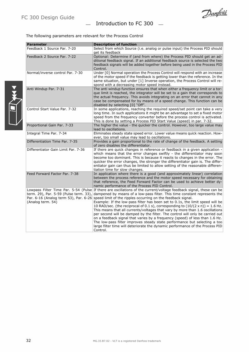
The following parameters are relevant for the Process Control
Parameter Description of functionFeedback 1 Source Par. 7-20 Select from which Source (i.e. analog or pulse input) the Process PID should
get its feedbackFeedback 2 Source Par. 7-22 Optional: Determine if (and from where) the Process PID should get an ad-
ditional feedback signal. If an additional feedback source is selected the twofeedback signals will be added together before being used in the Process PIDControl.
Normal/inverse control Par. 7-30 Under [0] Normal operation the Process Control will respond with an increaseof the motor speed if the feedback is getting lower than the reference. In thesame situation, but under [1] Inverse operation, the Process Control will re-spond with a decreasing motor speed instead.
Anti Windup Par. 7-31 The anti windup function ensures that when either a frequency limit or a tor-que limit is reached, the integrator will be set to a gain that corresponds tothe actual frequency. This avoids integrating on an error that cannot in anycase be compensated for by means of a speed change. This function can bedisabled by selecting [0] Off.
Control Start Value Par. 7-32 In some applications, reaching the required speed/set point can take a verylong time. In such applications it might be an advantage to set a fixed motorspeed from the frequency converter before the process control is activated.This is done by setting a Process PID Start Value (speed) in par. 7-32.
Proportional Gain Par. 7-33 The higher the value - the quicker the control. However, too large value maylead to oscillations.
Integral Time Par. 7-34 Eliminates steady state speed error. Lower value means quick reaction. How-ever, too small value may lead to oscillations.
Differentiation Time Par. 7-35 Provides a gain proportional to the rate of change of the feedback. A settingof zero disables the differentiator.
Differentiator Gain Limit Par. 7-36 If there are quick changes in reference or feedback in a given application -which means that the error changes swiftly - the differentiator may soonbecome too dominant. This is because it reacts to changes in the error. Thequicker the error changes, the stronger the differentiator gain is. The differ-entiator gain can thus be limited to allow setting of the reasonable differen-tiation time for slow changes.
Feed Forward Factor Par. 7-38 In application where there is a good (and approximately linear) correlationbetween the process reference and the motor speed necessary for obtainingthat reference, the Feed Forward Factor can be used to achieve better dy-namic performance of the Process PID Control.
Lowpass Filter Time Par. 5-54 (Pulseterm. 29), Par. 5-59 (Pulse term. 33),Par. 6-16 (Analog term 53), Par. 6-26(Analog term. 54)
If there are oscillations of the current/voltage feedback signal, these can bedampened by means of a low-pass filter. This time constant represents thespeed limit of the ripples occurring on the feedback signal.Example: If the low-pass filter has been set to 0.1s, the limit speed will be10 RAD/sec. (the reciprocal of 0.1 s), corresponding to (10/(2 x π)) = 1.6 Hz.This means that all currents/voltages that vary by more than 1.6 oscillationsper second will be damped by the filter. The control will only be carried outon a feedback signal that varies by a frequency (speed) of less than 1.6 Hz.The low-pass filter improves steady state performance but selecting a toolarge filter time will deteriorate the dynamic performance of the Process PIDControl.
FC 300 Design Guide Introduction to FC 300
32 MG.33.B7.02 - VLT is a registered Danfoss trademark

Example of Process PID Control
The following is an example of a Process PID Control used in a ventilation SYSTEM:
In a ventilation SYSTEM, the temperature is to besettable from - 5 - 35°C with a potentiometer of0-10 Volt. The set temperature must be kept con-stant, for which purpose the Process Control is tobe used.
The control is of the inverse type, which meansthat when the temperature increases, the venti-lation speed is increased as well, so as to generatemore air. When the temperature drops, the speedis reduced. The transmitter used is a temperaturesensor with a working range of -10-40°C, 4-20mA. Min. / Max. speed 300 / 1500 RPM.
NB!The example shows a two-wire trans-mitter.
1. Start/Stop via switch connected to terminal 18.
2. Temperature reference via potentiometer (-5-35°C, 0-10 VDC) connected to terminal 53.
3. Temperature feedback via transmitter (-10-40°C, 4-20 mA) connected to terminal 54. SwitchS202 set to ON (current input).
Example of Process PID Control set-up
FC 300 Design Guide Introduction to FC 300
MG.33.B7.02 - VLT is a registered Danfoss trademark 33

Function Par.no.
Setting
Initialize the frequency converter 14-22 [2] Initialization - make a power cycling - press reset1) Set motor parameters:Set the motor parameters according toname plate data
1-2* As stated on motor name plate
Perform a full Automation Motor Adapta-tion
1-29 [1] Enable complete AMA
2) Check that motor is running in the right direction.When motor is connected to frequency converter with straight forward phase order as U - U; V- V; W - W motor shaftusually turns clockwise seen into shaft end.Press Hand On LCP key. Check shaft di-rection by applying a manual reference.If motor turns opposite of required direc-tion:1. Change motor direction in par. 4-10
2. Turn off mains - wait for DC link to dis-
charge - switch two of the motor phases
4-10 Select correct motor shaft direction
Set configuration mode 1-00 [3] ProcessSet Local Mode Configuration 1-05 [0] Speed Open Loop3) Set reference configuration, ie. the range for reference handling. Set scaling of analog input in par. 6-xxSet reference/feedback unitsSet min. reference (10° C)Set max. reference (80° C)If set value is determined from a presetvalue (array parameter), set other refer-ence sources to No Function
3-013-023-033-10
[60] ° C Unit shown on display-5° C35° C[0] 35%
Ref =P3− 10(0)
100 × ((P3− 03) − (p3− 02)) = 24, 5° CPar. 3-14 to par. 3-18 [0] = No Function
4) Adjust limits for the frequency converter:Set ramp times to an appropriate value as20 sec.
3-413-42
20 sec.20 sec.
Set min. speed limitsSet motor speed max. limitSet max. output frequency
4-114-134-19
300 RPM1500 RPM60 Hz
Set S201 or S202 to wanted analog input function (Voltage (V) or milli-Amps (I))NOTE! Switches are sensitive - Make a power cycling keeping default setting of V5) Scale analog inputs used for reference and feedbackSet terminal 53 low voltageSet terminal 53 high voltageSet terminal 54 low feedback valueSet terminal 54 high feedback valueSet feedback source
6-106-116-246-257-20
0 V10 V-5° C35° C[2] Analog input 54
6) Basic PID settingsProcess PID Normal/Inverse 7-30 [0] NormalProcess PID Anti Wind-up 7-31 [1] OnProcess PID start speed 7-37 300 rpmSave parameters to LCP 0-50 [1] All to LCP
FC 300 Design Guide Introduction to FC 300
34 MG.33.B7.02 - VLT is a registered Danfoss trademark

Optimisation of the process regulator
The basic settings have now been made; all that needs to be done is to optimise the proportional gain,the integration time and the differentiation time (par. 7-33, 7-34, 7-35). In most processes, this can bedone by following the guidelines given below.
1. Start the motor
2. Set par. 7-33 (Proportional Gain) to 0.3 and increase it until the feedback signal again begins tovary continuously. Then reduce the value until the feedback signal has stabilised. Now lower theproportional gain by 40-60%.
3. Set par. 7-34 (Integration Time) to 20 sec. and reduce the value until the feedback signal againbegins to vary continuously. Increase the integration time until the feedback signal stabilises,followed by an increase of 15-50%.
4. Only use par. 7-35 for very fast-acting SYSTEMs only (differentiation time). The typical value isfour times the set integration time. The differentiator should only be used when the setting ofthe proportional gain and the integration time has been fully optimised. Make sure that oscilla-tions on the feedback signal is sufficiently dampened by the lowpass filter on the feedback signal.
NB!If necessary, start/stop can be activated a number of times in order to provoke a variation ofthe feedback signal.
Ziegler Nichols Tuning Method
In order to tune the PID controls of the frequency converter, several tuning methods can be used. Oneapproach is to use a technique which was developed in the 1950s but which has stood the test of timeand is still used today. This method is known as the Ziegler Nichols tuning.
NB!The method described must not be used on applications that could be damaged by the oscil-lations created by marginally stable control settings.
The criteria for adjusting the parameters arebased on evaluating the SYSTEM at the limit ofstability rather than on taking a step response. Weincrease the proportional gain until we observecontinuous oscillations (as measured on the feed-back), that is, until the SYSTEM becomes margin-ally stable. The corresponding gain (Ku) (calledthe ultimate gain) and the period of the oscillation(Pu) (also called the ultimate period) are deter-mined as shown in Figure 1. Figure 1: Marginally stable SYSTEM
Pu should be measured when the amplitude of oscillation is quite small. Then we back off from thisgain again, as shown in Table 1.
Ku is the gain at which the oscillation is obtained.
Type of Control Proportional Gain Integral Time Differentiation TimePI-control 0.45 * Ku 0.833 * Pu -PID tight control 0.6 * Ku 0.5 * Pu 0.125 * Pu
PID some overshoot 0.33 * Ku 0.5 * Pu 0.33 * Pu
Table 1: Ziegler Nichols tuning for regulator, based on a stability boundary.Experience has shown that the control setting according to Ziegler Nichols rule provides a good closedloop response for many SYSTEMs. The process operator can do the final tuning of the control iterativelyto yield satisfactory control.
FC 300 Design Guide Introduction to FC 300
MG.33.B7.02 - VLT is a registered Danfoss trademark 35

Step-by-step Description:
Step 1: Select only Proportional Control, meaning that the Integral time is selected to the maximumvalue, while the differentiation time is selected to zero.
Step 2: Increase the value of the proportional gain until the point of instability is reached (sustainedoscillations) and the critical value of gain, Ku , is reached.
Step 3: Measure the period of oscillation to obtain the critical time constant, Pu .
Step 4: Use the table above to calculate the necessary PID control parameters.
General Aspects of EMC Emissions
Electrical interference is usually conducted at frequences in the range 150 kHz to 30 MHz. Airborne in-terference from the drive system in the range 30 MHz to 1 GHz is generated from the inverter, motorcable, and the motor.As shown in the illustration below, capacitive currents in the motor cable coupled with a high dV/dt fromthe motor voltage generate leakage currents.The use of a screened motor cable increases the leakage current (see illustration below) becausescreened cables have higher capacitance to earth than unscreened cables. If the leakage current is notfiltered, it will cause greater interference on the mains in the radio frequency range below approx. 5 MHz.Since the leakage current (I1) is carried back to the unit through the screen (I 3), there will in principleonly be a small electro-magnetic field (I4) from the screened motor cable according to the below figure.
The screen reduces the radiated interference but increases the low-frequency interference on the mains.The motor cable screen must be connected to the frequency converter enclosure as well as on the motorenclosure. This is best done by using integrated screen clamps so as to avoid twisted screen ends (pig-tails). These increase the screen impedance at higher frequencies, which reduces the screen effect andincreases the leakage current (I4).If a screened cable is used for Profibus, standard bus, relay, control cable, signal interface, and brake,the screen must be mounted on the enclosure at both ends. In some situations, however, it will be nec-essary to break the screen to avoid current loops.
If the screen is to be placed on a mounting plate for the frequency converter, the mounting plate mustbe made of metal, because the screen currents have to be conveyed back to the unit. Moreover, ensuregood electrical contact from the mounting plate through the mounting screws to the frequency converterchassis.
NB!When unscreened cables are used, some emission requirements are not complied with, al-though the immunity requirements are observed.
In order to reduce the interference level from the entire system (unit + installation), make motor andbrake cables as short as possible. Avoid placing cables with a sensitive signal level alongside motor andbrake cables. Radio interference higher than 50 MHz (airborne) is especially generated by the controlelectronics.
FC 300 Design Guide Introduction to FC 300
36 MG.33.B7.02 - VLT is a registered Danfoss trademark

EMC Test Results (Emission, Immunity)
The following test results have been obtained using a SYSTEM with a frequency converter (with op-tions if relevant), a screened control cable, a control box with potentiometer, as well as a motor andmotor screened cable. Conducted emission Radiated emission Industrial environment Housing,
trades andlight indus-
tries
Industrial en-vironment
Housing, tradesand light indus-
tries
EN 55011Class A2
EN 55011Class A1
EN 55011Class B
EN 55011Class A1
EN 55011 Class BSetupFC 301/FC 302 (H2)0-3.7 kW 200-240 V0-7.5 kW 380-480/500 V
5 m5 m
NoNo
NoNo
NoNo
NoNo
FC 301 (H1)0-3.7 kW 200-240 V0-7.5 kW 380-480 V
75 m75 m
50 m50 m
10 m10 m
YesYes
NoNo
FC 301 (H3)0-1.5 kW 200-240 V0-1.5 kW 380-480 V
50 m50 m
25 m25 m
2.5 m2.5 m
YesYes
NoNo
FC 302 (H1)0-3.7 kW 200-240 V0-7.5 kW 380-500 V
150 m150 m
150 m150 m
50 m50 m
YesYes
NoNo
FC 301/FC 302 (H2)11-22 kW 380-480/500 V
25 m No No No No
FC 301 (H1)11-22 kW 380-480 V 75 m 50 m 10 m Yes NoFC 302 (H1) 11-22 kW 380-500 V 150 m 150 m 50 m Yes NoFC 302 (HX)0.75 - 7.5 kW550 - 600 V No No No No No
HX, H1, H2 or H3 is defined in the type code pos. 16 - 17 for EMC filtersHX - No EMC filters build in the frequency converter (600 V units only)H1 - Integrated EMC filter. Fulfil Class A1/BH2 - No additional EMC filter. Fulfil Class A2H3 - Integrated EMC filter. Fulfil class A1/B (Enclosure type A1 only)
FC 300 Design Guide Introduction to FC 300
MG.33.B7.02 - VLT is a registered Danfoss trademark 37
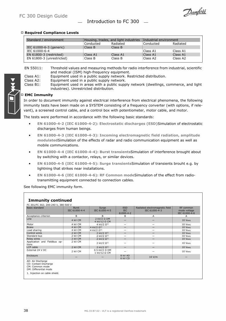
Required Compliance Levels
Standard / environment Housing, trades, and light industries Industrial environment Conducted Radiated Conducted RadiatedIEC 61000-6-3 (generic) Class B Class BIEC 61000-6-4 Class A1 Class A1EN 61800-3 (restricted) Class A1 Class A1 Class A1 Class A1EN 61800-3 (unrestricted) Class B Class B Class A2 Class A2
EN 55011: Threshold values and measuring methods for radio interference from industrial, scientificand medical (ISM) high-frequency equipment.
Class A1: Equipment used in a public supply network. Restricted distribution.Class A2: Equipment used in a public supply network.Class B1: Equipment used in areas with a public supply network (dwellings, commerce, and light
industries). Unrestricted distribution.
EMC Immunity
In order to document immunity against electrical interference from electrical phenomena, the followingimmunity tests have been made on a SYSTEM consisting of a frequency converter (with options, if rele-vant), a screened control cable, and a control box with potentiometer, motor cable, and motor.
The tests were performed in accordance with the following basic standards:
EN 61000-4-2 (IEC 61000-4-2): Electrostatic discharges (ESD)Simulation of electrostaticdischarges from human beings.
EN 61000-4-3 (IEC 61000-4-3): Incoming electromagnetic field radiation, amplitudemodulatedSimulation of the effects of radar and radio communication equipment as well asmobile communications.
EN 61000-4-4 (IEC 61000-4-4): Burst transientsSimulation of interference brought aboutby switching with a contactor, relays, or similar devices.
EN 61000-4-5 (IEC 61000-4-5): Surge transientsSimulation of transients brouht e.g. bylightning that strikes near installations.
EN 61000-4-6 (IEC 61000-4-6): RF Common modeSimulation of the effect from radio-transmitting equipment connected to connection cables.
See following EMC immunity form.
Immunity continuedFC 301/FC 302; 200-240 V, 380-500 VBasic standard Burst
IEC 61000-4-4Surge
IEC 61000-4-5ESDIEC
61000-4-2
Radiated electromagnetic fieldIEC 61000-4-3
RF commonmode voltageIEC 61000-4-6
Acceptance criterion B B B A ALine 4 kV CM 2 kV/2 Ω DM
4 kV/12 Ω CM 10 VRMS
Motor 4 kV CM 4 kV/2 Ω1) 10 VRMS
Brake 4 kV CM 4 kV/2 Ω1) 10 VRMS
Load sharing 4 kV CM 4 kV/2 Ω1) 10 VRMS
Control wires 2 kV CM 2 kV/2 Ω1) 10 VRMS
Standard bus 2 kV CM 2 kV/2 Ω1) 10 VRMS
Relay wires 2 kV CM 2 kV/2 Ω1) 10 VRMS
Application and Fieldbus op-tions
2 kV CM2 kV/2 Ω1) 10 VRMS
LCP cable 2 kV CM 2 kV/2 Ω1) 10 VRMS
External 24 V DC 2 kV CM 0.5 kV/2 Ω DM1 kV/12 Ω CM 10 VRMS
Enclosure 8 kV AD6 kV CD 10 V/m
AD: Air DischargeCD: Contact DischargeCM: Common modeDM: Differential mode
1. Injection on cable shield.
FC 300 Design Guide Introduction to FC 300
38 MG.33.B7.02 - VLT is a registered Danfoss trademark

Galvanic Isolation (PELV)
PELV offers protection by way of extra low voltage. Protection against electric shock is ensured whenthe electrical supply is of the PELV type and the installation is made as described in local/national regu-lations on PELV supplies.
All control terminals and relay terminals 01-03/04-06 comply with PELV (Protective Extra Low Voltage)(Does not apply to 525-600 V units and at grounded Delta leg above 300 V).
Galvanic (ensured) isolation is obtained by fulfilling requirements for higher isolation and by providingthe relevant creapage/clearance distances. These requirements are described in the EN 61800-5-1standard.
The components that make up the electrical isolation, as described below, also comply with the require-ments for higher isolation and the relevant test as described in EN 61800-5-1.The PELV galvanic isolation can be shown in six locations (see illustration):
In order to maintain PELV all connections made to the control terminals must be PELV, e.g. thermistormust be reinforced/double insulated.
1. Power supply (SMPS) incl. signal isolationof UDC, indicating the intermediate currentvoltage.
2. Gate drive that runs the IGBTs (triggertransformers/opto-couplers).
3. Current transducers.
4. Opto-coupler, brake module.
5. Internal inrush, RFI, and temperaturemeasurement circuits.
6. Custom relays. Galvanic isolation
The functional galvanic isolation (a and b on drawing) is for the 24 V back-up option and for the RS 485standard bus interface.
FC 300 Design Guide Introduction to FC 300
MG.33.B7.02 - VLT is a registered Danfoss trademark 39
Earth Leakage Current
Warning:Touching the electrical parts may be fatal - even after the equipment has been disconnectedfrom mains.Also make sure that other voltage inputs have been disconnected, such as load sharing (link-age of DC intermediate circuit), as well as the motor connection for kinetic back-up.Using VLT AutomationDrive FC 300: wait at least 15 minutes.Shorter time is allowed only if indicated on the nameplate for the specific unit.
Leakage CurrentThe earth leakage current from the FC 300 exceeds 3.5 mA. To ensure that the earth cablehas a good mechanical connection to the earth connection (terminal 95), the cable cross sec-
tion must be at least 10 mm2 or 2 rated earth wires terminated separately.Residual Current DeviceThis product can cause a d.c. current in the protective conductor. Where a residual currentdevice ( RCD ) is used for extra protection , only an RCD of Type B (time delayed) shall beused on the supply side of this product. See also RCD Application Note MN.90.GX.02.Protective earthing of the frequency converter and the use of RCD's must always follow na-tional and local regulations.
Selection of Brake Resistor
To handle higher demands by generatoric braking a brake resistor is necessary. Using a brake resistorensures that the energy is absorbed in the brake resistor and not in the frequency converter.
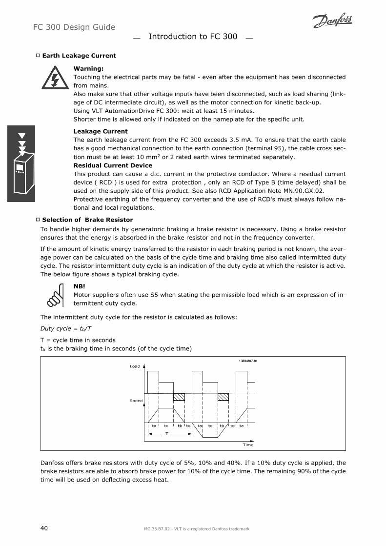
If the amount of kinetic energy transferred to the resistor in each braking period is not known, the aver-age power can be calculated on the basis of the cycle time and braking time also called intermitted dutycycle. The resistor intermittent duty cycle is an indication of the duty cycle at which the resistor is active.The below figure shows a typical braking cycle.
NB!Motor suppliers often use S5 when stating the permissible load which is an expression of in-termittent duty cycle.
The intermittent duty cycle for the resistor is calculated as follows:
Duty cycle = tb/T
T = cycle time in secondstb is the braking time in seconds (of the cycle time)
Danfoss offers brake resistors with duty cycle of 5%, 10% and 40%. If a 10% duty cycle is applied, thebrake resistors are able to absorb brake power for 10% of the cycle time. The remaining 90% of the cycletime will be used on deflecting excess heat.
FC 300 Design Guide Introduction to FC 300
40 MG.33.B7.02 - VLT is a registered Danfoss trademark

The max. permissible load on the brake resistor is stated as a peak power at a given intermittent dutycycle and can be calculated as:
The brake resistance is calculated as shown:PPEAK = PMOTOR x MBR(%) x η MOTOR x η VLT [W] Rbr =
U dc2Ppeak
= Ω
As can be seen, the brake resistance depends on the intermediate circuit voltage (UDC).The FC 301 and FC 302 brake function is settled in 3 areas of mains:
Size Brake active Warning before cut out Cut out (trip)FC 301 / 302 3 x 200-240 V 390 V (UDC) 405 V 410 VFC 301 3 x 380-480 V 778 V 810 V 820 VFC 302 3 x 380-500 V 810 V 840 V 850 VFC 302 3 x 525-600 V 943 V 965 V 975 V
NB!Check that the brake resistor can cope with a voltage of 410 V, 820 V, 850 V or 975 V - unlessDanfoss brake resistors are used.
Danfoss recommends the brake resistance RREC,i.e. one that guarantees that the frequency con-verter is able to brake at the highest braking tor-que (Mbr) of 160%. The formula can be written as:
Rrec =U dc2 x 100
Pmotor x MBR ( % ) x ϕVLT x ϕmotor= Ω
η motor is typically at 0.90 ηVLT is typically at 0.98
For 200 V, 480 V, 500 V and 600 V frequency converters, RREC at 160% braking torque is written as:
200V : Rrec = 107780PMotor
Ω
380V : R = 375300PMotor
Ω 480V : R = 428914PMotor
Ω
500V : Rrec =464923PMotor
Ω
600V : Rrec =630137PMotor
Ω
690V : Rrec =832664PMotor
Ω
1. For FC 300 frequency converters ≤ 7.5 kW shaft output2. For FC 300 frequency converters > 7.5 kW shaft output
NB!The resistor brake circuit resistance selected should not be higher than that recommended byDanfoss. If a brake resistor with a higher ohmic value is selected, the 160% braking torquemay not be achieved because there is a risk that the frequency converter cuts out for safetyreasons.
NB!If a short circuit in the brake transistor occurs, power dissipation in the brake resistor is onlyprevented by using a mains switch or contactor to disconnect the mains for the frequencyconverter. (The contactor can be controlled by the frequency converter).
FC 300 Design Guide Introduction to FC 300
MG.33.B7.02 - VLT is a registered Danfoss trademark 41

NB!Do not touch the brake resistor as itcan get very hot while/after braking.
Control with Brake Function
The brake is to limit the voltage in the intermediate circuit when the motor acts as a generator. Thisoccurs, for example, when the load drives the motor and the power accumulates on the DC link. Thebrake is built up as a chopper circuit with the connection of an external brake resistor. Placing the brakeresistor externally offers the following advantages:
- The brake resistor can be selected on the basis of the application in question.
- The brake energy can be dissipated outside the control panel, i.e. where the energy can be uti-lized.
- The electronics of the frequency converter will not be overheated if the brake resistor is over-loaded.
The brake is protected against short-circuiting of the brake resistor, and the brake transistor is monitoredto ensure that short-circuiting of the transistor is detected. A relay/digital output can be used for pro-tecting the brake resistor against overloading in connection with a fault in the frequency converter.In addition, the brake makes it possible to read out the momentary power and the mean power for thelatest 120 seconds. The brake can also monitor the power energizing and make sure it does not exceeda limit selected in par. 2-12. In par. 2-13, select the function to carry out when the power transmittedto the brake resistor exceeds the limit set in par. 2-12.
NB!Monitoring the brake power is not a safety function; a thermal switch is required for thatpurpose. The brake resistor circuit is not earth leakage protected.
Over voltage control (OVC) (exclusive brake resistor) can be selected as an alternative brake function inpar. 2-17. This function is active for all units. The function ensures that a trip can be avoided if the DClink voltage increases. This is done by increasing the output frequency to limit the voltage from the DClink. It is a very useful function, e.g. if the ramp-down time is too short since tripping of the frequencyconverter is avoided. In this situation the ramp-down time is extended.
Control of Mechanical Brake
For hoisting applications, it is necessary to be able to control an electro-magnetic brake. For controllingthe brake, a relay output (relay1 or relay2) or a programmed digital output (terminal 27 or 29) is re-quired. Normally, this output must be closed for as long as the frequency converter is unable to holdthe motor, e.g. because of too big load. In par. 5-40 (Array parameter), par. 5-30, or par. 5-31 (digitaloutput 27 or 29), select mechanical brake control [32] for applications with an electro-magnetic brake.
When mechanical brake control [32] is selected, the mechanical brake relay stays closed during startuntil the output current is above the level selected in par. 2-20 Release Brake Current. During stop, themechanical brake will close when the speed is below the level selected in par. 2-21 Activate Brake Speed[RPM]. If the frequency converter is brought into an alarm condition, i.e. over-voltage situation, the me-chanical brake immediately cuts in. This is also the case during safe stop.
FC 300 Design Guide Introduction to FC 300
42 MG.33.B7.02 - VLT is a registered Danfoss trademark

Step-by-step Description
In hoisting/lowering applications, it must be possible to control an electro-mehanical brake.
To control the mechanical brake any relay output or digital output (terminal 27 or 29) can beused, if necessary use a suitable magnetic contactor.
Ensure that the output stays voltage-free as long as the frequency converter is unable to drivethe motor, for example due to the load being to heavy or due to the fact that the motor has notbeen dismounted yet.
Select Mechanical brake control [32] in par. 5-4* (or in par. 5-3*) before connecting the me-chanical brake.
The brake is released when the motor current exceeds the preset value in par. 2-20.
The brake is engaged when the output frequency is less than the frequency set in par. 2-21 or2-22 and only if the frequency converter carries out a stop command.
NB!For vertical lifting or hoisting applications it is strongly recommended to ensure that the loadcan be stopped in case of an emergency or a malfunction of a single part such as a contactor,etc.If the frequency converter is in alarm mode or in an over voltage situation, the mechanicalbrake cuts in.
Cabelling
EMC (twisted cables/shielding)To reduce the electrical noise from the wires between the brake resistor and the frequency converter,the wires must be twisted.
For enhanced EMC performance a metal screen can be used.
Smart Logic Control
The Smart Logic Control (SLC) is essentially a sequence of user defined actions (see par. 13-52) executedby the SLC when the associated user defined event (see par. 13-51) is evaluated as TRUE by the SLC.Events and actions are each numbered and are linked in pairs called states. This means that when event[1] is fulfilled (attains the value TRUE), action [1] is executed. After this, the conditions of event [2] willbe evaluated and if evaluated TRUE, action [2]will be executed and so on. Events and actions are placedin array parameters.
Only one event will be evaluated at any time. If an event is evaluated as FALSE, nothing happens (in theSLC) during the present scan interval and no other events will be evaluated. This means that when the
FC 300 Design Guide Introduction to FC 300
MG.33.B7.02 - VLT is a registered Danfoss trademark 43

SLC starts, it evaluates event [1] (and only event [1]) each scan interval. Only when event [1] is eval-uated TRUE, the SLC executes action [1] and starts evaluating event [2].
It is possible to program from 0 to 20 events andactions. When the last event / action has beenexecuted, the sequence starts over again fromevent [1] / action [1]. The illustration shows anexample with three events / actions:
Extreme Running Conditions
Short Circuit (Motor Phase Phase)The frequency converter is protected against short circuits by means of current measurement in each ofthe three motor phases or in the DC link. A short circuit between two output phases will cause anovercurrent in the inverter. The inverter will be turned off individually when the short circuit currentexceeds the permitted value (Alarm 16 Trip Lock.To protect the drive against a short circuit at the load sharing and brake outputs please see the designguidelines.
Switching on the OutputSwitching on the output between the motor and the frequency converter is fully permitted. You cannotdamage the frequency converter in any way by switching on the output. However, fault messages mayappear.
FC 300 Design Guide Introduction to FC 300
44 MG.33.B7.02 - VLT is a registered Danfoss trademark

Motor-generated OvervoltageThe voltage in the intermediate circuit is increased when the motor acts as a generator. This occurs infollowing cases:
1. The load drives the motor (at constant output frequency from the frequency converter), ie. theload generates energy.
2. During deceleration ("ramp-down") if the moment of inertia is high, the friction is low and theramp-down time is too short for the energy to be dissipated as a loss in the frequency converter,the motor and the installation.
3. In-correct slip compensation setting may cause higher DC link voltage.
The control unit may attempt to correct the ramp if possible (par. 2-17 Over-voltage Control.The inverter turns off to protect the transistors and the intermediate circuit capacitors when a certainvoltage level is reached.See par. 2-10 and par. 2-17 to select the method used for controlling the intermediate circuit voltagelevel.
Mains Drop-outDuring a mains drop-out, the frequency converter keeps running until the intermediate circuit voltagedrops below the minimum stop level, which is typically 15% below the frequency converter's lowest ratedsupply voltage.
The mains voltage before the drop-out and the motor load determines how long it takes for the inverterto coast.
Static Overload in VVCplus modeWhen the frequency converter is overloaded (the torque limit in par. 4-16/4-17 is reached), the controlsreduces the output frequency to reduce the load.If the overload is excessive, a current may occur that makes the frequency converter cut out after approx.5-10 s.
Operation within the torque limit is limited in time (0-60 s) in par. 14-25.
Motor Thermal Protection
The motor temperature is calculated on the basisof motor current, output frequency, and time orthermistor. See par. 1-90 in the chapter How toProgramme.
Safe Stop of FC 300
The FC 302, and also the FC301 in A1 enclosure,can perform the safety function Safe Torque Off(As defined by draft CD IEC 61800-5-2) or StopCategory 0 (as defined in EN 60204-1).
FC 301 A1 enclosure: When Safe Stop is includedin the drive position 18 of Type Code must be ei-
ther T or U. If position 18 is B or X Safe StopTerminal 37 is not included!Example:Type Code for FC 301 A1 with Safe Stop:FC-301PK75T4Z20H4TGCXXXSXXXXA0BXCXXXXD0
FC 300 Design Guide Introduction to FC 300
MG.33.B7.02 - VLT is a registered Danfoss trademark 45

It is designed and approved suitable for the re-quirements of Safety Category 3 in EN 954-1. Thisfunctionality is called Safe Stop. Prior to integra-tion and use of Safe Stop in an installation, athorough risk analysis on the installation must becarried out in order to determine whether the SafeStop functionality and safety category are appro-priate and sufficient. In order to install and usethe Safe Stop function in accordance with the re-quirements of Safety Category 3 in EN 954-1, therelated information and instructions of the FC 300Design Guide MG.33.BX.YY must be followed! Theinformation and instructions of the Operating In-structions are not sufficient for a correct and safeuse of the Safe Stop functionality!
Safe Stop Installation (FC 302 and FC 301 - A1 enclosure only)
To carry out an installation of a Category 0 Stop(EN60204) in conformance with Safety Category3 (EN954-1), follow these instructions:
1. The bridge (jumper) between Terminal 37and 24 V DC must be removed. Cutting orbreaking the jumper is not sufficient. Re-move it entirely to avoid short-circuiting.See jumper on illustration.
2. Connect terminal 37 to 24 V DC by ashort-circuit protected cable. The 24 V DCvoltage supply must be interruptible by anEN954-1 Category 3 circuit interrupt de-vice. If the interrupt device and the fre-quency converter are placed in the sameinstallation panel, you can use a regularcable instead of a protected one.
Bridge jumper between terminal 37 and 24 VDC
The illustration below shows a Stopping Category 0 (EN 60204-1) with safety Cat. 3 (EN 954-1). Thecircuit interrupt is caused by an opening door contact. The illustration also shows how to connect a non-safety related hardware coast.
FC 300 Design Guide Introduction to FC 300
46 MG.33.B7.02 - VLT is a registered Danfoss trademark

Illustration of the essential aspects of an installation to achieve a Stopping Category 0 (EN 60204-1) with safety Cat.3 (EN 954-1).
Safe Stop Commissioning Test
After installation and before first operation, perform a commissioning test of an installation or applicationmaking use of FC 300 Safe Stop.Moreover, perform the test after each modification of the installation or application, which the FC 300Safe Stop is part of.The commissioning test:
1. Remove the 24 V DC voltage supply to terminal 37 by the interrupt device while the motor isdriven by the FC 302 (i.e. mains supply is not interrupted). The test step is passed if the motorreacts with a coast and the mechanical brake (if connected) is activated.
2. Then send Reset signal (via Bus, Digital I/O, or [Reset] key). The test step is passed if the motorremains in the Safe Stop state, and the mechanical brake (if connected) remains activated.
3. Then reapply 24 V DC to terminal 37. The test step is passed if the motor remains in the coastedstate, and the mechanical brake (if connected) remains activated.
4. Then send Reset signal (via Bus, Digital I/O, or [Reset] key). The test step is passed if the motorgets operational again.
5. The commissioning test is passed if all four test steps are passed.
NB!The Safe Stop function of FC 302 can be used for asynchronous and synchronous motors. Itmay happen that two faults occur in the frequency converter's power semiconductor. Whenusing synchronous motors this may cause a residual rotation. The rotation can be calculatedto Angle=360/(Number of Poles). The application using synchronous motors must take thisinto consideration and ensure that this is not a safety critical issue. This situation is not rele-vant for asynchronous motors.
NB!In order to use the Safe Stop functionality in conformance with the requirements of EN-954-1Category 3, a number of conditions must be fulfilled by the installation of Safe Stop. Pleasesee section Safe Stop Installation for further information.
NB!The frequency converter does not provide a safety-related protection against unintended ormalicious voltage supply to terminal 37 and subsequent reset. Provide this protection via theinterrupt device, at the application level, or organisational level.For more information - see section Safe Stop Installation.
FC 300 Design Guide Introduction to FC 300
MG.33.B7.02 - VLT is a registered Danfoss trademark 47

FC 300 Design Guide
48 MG.33.B7.02 - VLT is a registered Danfoss trademark

FC 300 Selection
Electrical Data
Mains Supply 3 x 200 - 240 VACFC 301/FC 302 PK25 PK37 PK55 PK75 P1K1 P1K5 P2K2 P3K0 P3K7Shaft Output [kW] 0.25 0.37 0.55 0.75 1.1 1.5 2.2 3 3.7Output current
Continuous(3 x 200-240 V ) [A] 1.8 2.4 3.5 4.6 6.6 7.5 10.6 12.5 16.7
Intermittent(3 x 200-240 V ) [A] 2.9 3.8 5.6 7.4 10.6 12.0 17.0 20.0 26.7
ContinuousKVA (208 V AC) [KVA] 0.65 0.86 1.26 1.66 2.38 2.70 3.82 4.50 6.00
Max. cable size(mains, motor, brake)[AWG] 2) [mm2]
24 - 10 AWG0.2 - 4 mm2
Max. input currentContinuous(3 x 200-240 V ) [A] 1.6 2.2 3.2 4.1 5.9 6.8 9.5 11.3 15.0
Intermittent(3 x 200-240 V ) [A] 2.6 3.5 5.1 6.6 9.4 10.9 15.2 18.1 24.0
Max. pre-fuses1) [A] 10 10 10 10 20 20 20 32 32EnvironmentEstimated power lossat rated max. load [W] 4) 21 29 42 54 63 82 116 155 185
Enclosure IP 20/IP 21 A2 A2 A2 A2 A2 A2 A2 A3 A3Enclosure IP 20 (FC 301 only) A1 A1 A1 A1 A1 - - - -Enclosure IP 55 A5 A5 A5 A5 A5 A5 A5 A5 A5Weight, enclosure IP20 [kg] 4.7 4.7 4.8 4.8 4.9 4.9 4.9 6.6 6.6A1 (IP 20) 2.7 2.7 2.7 2.7 2.7 2.7 - - -Efficiency 4) 0.94 0.94 0.95 0.95 0.96 0.96 0.96 0.96 0.96
0.25 - 3.7 kW only available as 160% high overload.
FC 300 Design Guide FC 300 Selection
MG.33.B7.02 - VLT is a registered Danfoss trademark 49

Main
s S
up
ply
3 x
38
0 -
50
0 V
AC
(FC
30
2),
3 x
38
0 -
48
0 V
AC
(FC
30
1)
PK 3
7PK
55
PK75
P1K
1P1
K5
P2K2
P3K0
P4K0
P5K5
P7K5
FC 3
01/F
C 3
02
Typ
ical
Shaf
t O
utp
ut
[kW
]0.3
70.5
50.7
51.1
1.5
2.2
34
5.5
7.5
Encl
osu
re I
P20/I
P21
A2
A2
A2
A2
A2
A2
A2
A2
A3
A3
Encl
osu
re I
P20 (
FC 3
01 o
nly
)A1
A1
A1
A1
Encl
osu
re I
P55
A5
A5
A5
A5
A5
A5
A5
A5
A5
A5
Ou
tpu
t cu
rren
tH
igh
overl
oad
16
0%
fo
r 1
min
ute
Shaf
t outp
ut
[kW
]0.3
70.5
50.7
51.1
1.5
2.2
34
5.5
7.5
Con
tinuous
(3 x
380-4
40 V
) [A
]1.3
1.8
2.4
34.1
5.6
7.2
10
13
16
Inte
rmitte
nt
(3 x
380-4
40 V
) [A
]2.1
2.9
3.8
4.8
6.6
9.0
11.5
16
20.8
25.6
Con
tinuous
(3 x
440-5
00 V
) [A
]1.2
1.6
2.1
2.7
3.4
4.8
6.3
8.2
11
14.5
Inte
rmitte
nt
(3 x
440-5
00 V
) [A
]1.9
2.6
3.4
4.3
5.4
7.7
10.1
13.1
17.6
23.2
Con
tinuous
KVA
(400 V
AC)
[KVA]
0.9
1.3
1.7
2.1
2.8
3.9
5.0
6.9
9.0
11.0
Con
tinuous
KVA
(460 V
AC)
[KVA]
0.9
1.3
1.7
2.4
2.7
3.8
5.0
6.5
8.8
11.6
Max
. ca
ble
siz
e(m
ains,
moto
r, b
rake
)[A
WG
] 2) [m
m2]
24 -
10 A
WG
0.2
- 4
mm
224 -
10 A
WG
0.2
- 4
mm
2
Max.
inp
ut
curr
en
tCon
tinuous
(3 x
380-4
40 V
) [
A]
1.2
1.6
2.2
2.7
3.7
5.0
6.5
9.0
11.7
14.4
Inte
rmitte
nt
(3 x
380-4
40 V
) [
A]
1.9
2.6
3.5
4.3
5.9
8.0
10.4
14.4
18.7
23.0
Con
tinuous
(3 x
440-5
00 V
) [A
]1.0
1.4
1.9
2.7
3.1
4.3
5.7
7.4
9.9
13.0
Inte
rmitte
nt
(3 x
440-5
00 V
) [A
]1.6
2.2
3.0
4.3
5.0
6.9
9.1
11.8
15.8
20.8
Max
. pre
-fuse
s1) [
A]
10
10
10
10
10
20
20
20
32
32
Envi
ronm
ent
Est
imat
ed p
ow
er loss
at r
ated
max
. lo
ad [
W]
4)
35
42
46
58
62
88
116
124
187
255
Wei
ght,
encl
osu
re I
P20
4.7
4.7
4.8
4.8
4.9
4.9
4.9
4.9
6.6
6.6
Encl
osu
re I
P55
13.5
13.5
13.5
13.5
13.5
13.5
13.5
13.5
14.2
14.2
Effic
iency
4)
0.9
30.9
50.9
60.9
60.9
70.9
70.9
70.9
70.9
70.9
70.3
7 -
7.5
kW
only
ava
ilable
as
160%
hig
h o
verload
.
FC 300 Design Guide FC 300 Selection
50 MG.33.B7.02 - VLT is a registered Danfoss trademark

Main
s S
up
ply
3 x
38
0 -
50
0 V
AC
(FC
30
2),
3 x
38
0 -
48
0 V
AC
(FC
30
1)
FC 3
01/F
C 3
02
P11K
P15K
P18K
P22K
Hig
h O
L160%
Norm
al O
L110%
Hig
h O
L160%
Norm
al O
L110%
Hig
h O
L160%
Norm
al O
L110%
Hig
h O
L160%
Norm
al O
L110%
Typ
ical
Shaf
t outp
ut
[kW
]11
15
15
18.5
18.5
22.0
22.0
30.0
Encl
osu
re I
P21
B1
B1
B2
B2
Encl
osu
re I
P55
B1
B1
B2
B2
Ou
tpu
t cu
rren
tContinuou
s(3
x 3
80-4
40 V
) [A
]24
32
32
37.5
37.5
44
44
61
Inte
rmitte
nt
(60 se
c ove
r-lo
ad)
(3 x
380-4
40 V
) [A
]38.4
35.2
51.2
41.3
60
48.4
70.4
67.1
Continuou
s(3
x 4
40-5
00 V
) [A
]21
27
27
34
34
40
40
52
Inte
rmitte
nt
(60 se
c ove
r-lo
ad)
(3 x
440-5
00 V
) [A
]33.6
29.7
43.2
37.4
54.4
44
64
57.2
Continuou
s KVA
(400 V
AC)
[KVA]
16.6
22.2
22.2
26
26
30.5
30.5
42.3
Continuou
s KVA
(460 V
AC)
[KVA]
21.5
27.1
31.9
41.4
Max.
inp
ut
curr
en
tContinuou
s(3
x 3
80-4
40 V
) [
A]
22
30
30
35
35
42
42
58
Inte
rmitte
nt
(60 se
c ove
r-lo
ad)
(3 x
380-4
40 V
) [
A]
35.2
33
48
38.5
56
46.2
67.2
63.8
Continuou
s(3
x 4
40-5
00 V
) [A
]20
25
25
32
32
38
38
49
Inte
rmitte
nt
(60 se
c ove
r-lo
ad)
(3 x
440-5
00 V
) [A
]32
27.5
40
35.2
51.2
41.8
60.8
53.9
M
ax.
cable
si
ze
[mm
2
/AW
G]
2)
16/6
16/6
35/2
35/2
M
ax.
pre
-fuse
s [A
] 1
63
63
63
80
Est
imat
ed p
ower
loss
at r
ated
max
. lo
ad [
W]
4)
272
382
382
454
454
513
513
721
W
eight,
encl
osu
re I
P21,
IP 5
5 [
kg]
23
23
28
28
Eff
icie
ncy
4)
0.9
80.9
80.9
80.9
8
FC 300 Design Guide FC 300 Selection
MG.33.B7.02 - VLT is a registered Danfoss trademark 51

Mains Supply 3 x 525 - 600 VAC (FC 302 only)FC 302Typical Shaft Output [kW]
0.75 1.1 1.5 2.2 3 3.7 4 5.5 7.5
Output currentContinuous(3 x 525-550 V ) [A] 1.8 2.6 2.9 4.1 5.2 - 6.4 9.5 11.5
Intermittent(3 x 525-550 V ) [A] 2.9 4.2 4.6 6.6 8.3 - 10.2 15.2 18.4
Continuous(3 x 525-600 V ) [A] 1.7 2.4 2.7 3.9 4.9 - 6.1 9.0 11.0
Intermittent(3 x 525-600 V ) [A] 2.7 3.8 4.3 6.2 7.8 - 9.8 14.4 17.6
Continuous kVA (525 V AC)[kVA] 1.7 2.5 2.8 3.9 5.0 - 6.1 9.0 11.0
Continuous kVA (575 V AC)[kVA] 1.7 2.4 2.7 3.9 4.9 - 6.1 9.0 11.0
Max. cable size(mains, motor, brake)[AWG] 2) [mm2]
24 - 10 AWG0.2 - 4 mm2 -
24 - 10 AWG0.2 - 4 mm2
Max. input currentContinuous(3 x 525-600 V ) [A] 1.7 2.4 2.7 4.1 5.2 - 5.8 8.6 10.4
Intermittent(3 x 525-600 V ) [A] 2.7 3.8 4.3 6.6 8.3 - 9.3 13.8 16.6
Max. pre-fuses1) [A] 10 10 10 20 20 - 20 32 32EnvironmentEstimated power lossat rated max. load [W] 4) 35 50 65 92 122 - 145 195 261
Enclosure IP 20Weight,enclosure IP20 [kg] 6.5 6.5 6.5 6.5 6.5 - 6.5 6.6 6.6
Efficiency 4) 0.97 0.97 0.97 0.97 0.97 - 0.97 0.97 0.97
1) For type of fuse see section Fuses.
2) American Wire Gauge.
3) Measured using 5 m screened motor cables at rated load and rated frequency.
4) The typical power loss is at nominal load conditions and expected to be within +/-15% (tol-erence relates to variety in voltage and cable conditions).Values are based on a typical motor efficiency (eff2/eff3 border line). Lower efficient motors willalso add to the power loss in the frequency converter and opposite.If the switching frequency is raised from nominal the power losses may rise significantly.LCP and typical control card power consumptions are included. Further options and customer loadmay add up to 30W to the losses. (Though typical only 4W extra for a fully loaded control card,or options for slot A or slot B, each).Although measurements are made with state of the art equipment, some measurement inaccur-acy must be allowed for (+/-5%).
FC 300 Design Guide FC 300 Selection
52 MG.33.B7.02 - VLT is a registered Danfoss trademark
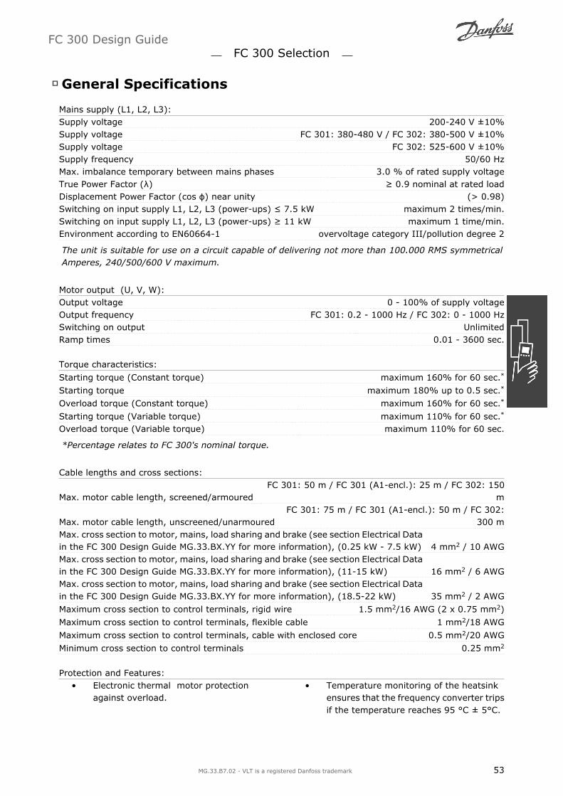
General Specifications
Mains supply (L1, L2, L3):Supply voltage 200-240 V ±10%Supply voltage FC 301: 380-480 V / FC 302: 380-500 V ±10%Supply voltage FC 302: 525-600 V ±10%Supply frequency 50/60 HzMax. imbalance temporary between mains phases 3.0 % of rated supply voltageTrue Power Factor (λ) ≥ 0.9 nominal at rated loadDisplacement Power Factor (cos ϕ) near unity (> 0.98)Switching on input supply L1, L2, L3 (power-ups) ≤ 7.5 kW maximum 2 times/min.Switching on input supply L1, L2, L3 (power-ups) ≥ 11 kW maximum 1 time/min.Environment according to EN60664-1 overvoltage category III/pollution degree 2
The unit is suitable for use on a circuit capable of delivering not more than 100.000 RMS symmetricalAmperes, 240/500/600 V maximum.
Motor output (U, V, W):Output voltage 0 - 100% of supply voltageOutput frequency FC 301: 0.2 - 1000 Hz / FC 302: 0 - 1000 HzSwitching on output UnlimitedRamp times 0.01 - 3600 sec.
Torque characteristics:
Starting torque (Constant torque) maximum 160% for 60 sec.*
Starting torque maximum 180% up to 0.5 sec.*
Overload torque (Constant torque) maximum 160% for 60 sec.*
Starting torque (Variable torque) maximum 110% for 60 sec.*
Overload torque (Variable torque) maximum 110% for 60 sec.
*Percentage relates to FC 300's nominal torque.
Cable lengths and cross sections:
Max. motor cable length, screened/armouredFC 301: 50 m / FC 301 (A1-encl.): 25 m / FC 302: 150
m
Max. motor cable length, unscreened/unarmouredFC 301: 75 m / FC 301 (A1-encl.): 50 m / FC 302:
300 mMax. cross section to motor, mains, load sharing and brake (see section Electrical Datain the FC 300 Design Guide MG.33.BX.YY for more information), (0.25 kW - 7.5 kW) 4 mm2 / 10 AWGMax. cross section to motor, mains, load sharing and brake (see section Electrical Datain the FC 300 Design Guide MG.33.BX.YY for more information), (11-15 kW) 16 mm2 / 6 AWGMax. cross section to motor, mains, load sharing and brake (see section Electrical Datain the FC 300 Design Guide MG.33.BX.YY for more information), (18.5-22 kW) 35 mm2 / 2 AWG
Maximum cross section to control terminals, rigid wire 1.5 mm2/16 AWG (2 x 0.75 mm2)
Maximum cross section to control terminals, flexible cable 1 mm2/18 AWG
Maximum cross section to control terminals, cable with enclosed core 0.5 mm2/20 AWG
Minimum cross section to control terminals 0.25 mm2
Protection and Features: Electronic thermal motor protection
against overload. Temperature monitoring of the heatsink
ensures that the frequency converter tripsif the temperature reaches 95 °C ± 5°C.
FC 300 Design Guide FC 300 Selection
MG.33.B7.02 - VLT is a registered Danfoss trademark 53

An overload temperature cannot be resetuntil the temperature of the heatsink isbelow 70 °C ± 5°C (Guideline - these tem-peratures may vary for different powersizes, enclosures etc.).
The frequency converter is protectedagainst short-circuits on motor terminalsU, V, W.
If a mains phase is missing, the frequencyconverter trips or issues a warning (de-pending on the load).
Monitoring of the intermediate circuitvoltage ensures that the frequency con-verter trips if the intermediate circuit volt-age is too low or too high.
The frequency converter is protectedagainst earth faults on motor terminals U,V, W.
Digital inputs:Programmable digital inputs FC 301: 4 (5) / FC 302: 4 (6)
Terminal number 18, 19, 271), 294), 32, 33,Logic PNP or NPNVoltage level 0 - 24 V DCVoltage level, logic'0' PNP < 5 V DCVoltage level, logic'1' PNP > 10 V DC
Voltage level, logic '0' NPN2) > 19 V DC
Voltage level, logic '1' NPN2) < 14 V DCMaximum voltage on input 28 V DCInput resistance, Ri approx. 4 kΩ
Safe stop Terminal 374):Terminal 37 is fixed PNP logic
Voltage level 0 - 24 V DCVoltage level, logic'0' PNP < 4 V DCVoltage level, logic'1' PNP >20 V DCNominal input current at 24 V 50 mA rmsNominal input current at 20 V 60 mA rmsInput capacitance 400 nF
All digital inputs are galvanically isolated from the supply voltage (PELV) and other high-voltage termi-nals.1) Terminals 27 and 29 can also be programmed as output.2) Except safe stop input Terminal 37.3) Terminal 37 is only available in FC 302 and FC 301 A1 with Safe Stop. It can only be used as safestop input. Terminal 37 is suitable for category 3 installations according to EN 954-1 (safe stop accordingto category 0 EN 60204-1) as required by the EU Machinery Directive 98/37/EC. Terminal 37 and theSafe Stop function are designed in conformance with EN 60204-1, EN 50178, EN 61800-2, EN 61800-3,and EN 954-1. For correct and safe use of the Safe Stop function follow the related information andinstructions in the Design Guide.4) FC 302 and FC 301 A1with Safe Stop only.
FC 300 Design Guide FC 300 Selection
54 MG.33.B7.02 - VLT is a registered Danfoss trademark

Analog inputs:Number of analog inputs 2Terminal number 53, 54Modes Voltage or currentMode select Switch S201 and switch S202Voltage mode Switch S201/switch S202 = OFF (U)Voltage level FC 301: 0 to + 10 / FC 302: -10 to +10 V (scaleable)Input resistance, Ri approx. 10 kΩMax. voltage ± 20 VCurrent mode Switch S201/switch S202 = ON (I)Current level 0/4 to 20 mA (scaleable)Input resistance, Ri approx. 200 ΩMax. current 30 mAResolution for analog inputs 10 bit (+ sign)Accuracy of analog inputs Max. error 0.5% of full scaleBandwidth FC 301: 20 Hz / FC 302: 100 Hz
The analog inputs are galvanically isolated from the supply voltage (PELV) and other high-voltage ter-minals.
Pulse/encoder inputs:Programmable pulse/encoder inputs 2/1
Terminal number pulse/encoder 29, 331) / 18, 32, 332) 3)
Max. frequency at terminal 18, 29, 32, 333) 110 kHz (Push-pull driven)
Max. frequency at terminal 18, 29, 32, 333) 5 kHz (open collector)
Min. frequency at terminal 18, 29, 32, 33 3) 4 HzVoltage level see section on Digital inputMaximum voltage on input 28 V DCInput resistance, Ri approx. 4 kΩPulse input accuracy (0.1 - 1 kHz) Max. error: 0.1% of full scaleEncoder input accuracy (1 - 110 kHz) Max. error: 0.05 % of full scale32 (A), 33 (B) and 18 (Z) 1
The pulse and encoder inputs (terminals 18, 29, 32, 33) are galvanically isolated from the supply voltage(PELV) and other high-voltage terminals.1) Pulse inputs are 29 and 332) Encoder inputs: 32 = A, and 33 = B3) Terminal 29: Only FC 302
FC 300 Design Guide FC 300 Selection
MG.33.B7.02 - VLT is a registered Danfoss trademark 55

Analog output:Number of programmable analog outputs 1Terminal number 42Current range at analog output 0/4 - 20 mAMax. load to common at analog output 500 ΩAccuracy on analog output Max. error: 0.5 % of full scaleResolution on analog output 12 bit
The analog output is galvanically isolated from the supply voltage (PELV) and other high-voltage ter-minals.
Control card, RS 485 serial communication:Terminal number 68 (P,TX+, RX+), 69 (N,TX-, RX-)Terminal number 61 Common for terminals 68 and 69
The RS 485 serial communication circuit is functionally separated from other central circuits and gal-vanically isolated from the supplier voltage (PELV).
Digital output:Programmable digital/pulse outputs 2
Terminal number 27, 29 1) 2)
Voltage level at digital/frequency output 0 - 24 VMax. output current (sink or source) 40 mAMax. load at frequency output 1 kΩMax. capacitive load at frequency output 10 nFMinimum output frequency at frequency output 0 HzMaximum output frequency at frequency output 32 kHzAccuracy of frequency output Max. error: 0.1 % of full scaleResolution of frequency outputs 12 bit
1) Terminal 27 and 29 can also be programmed as input.2) Terminal 29: Only FC 302.
The digital output is galvanically isolated from the supply voltage (PELV) and other high-voltage termi-nals.
Control card, 24 V DC output:Terminal number 12, 13Max. load FC 301: 130 mA / FC 302: 200 mA
The 24 V DC supply is galvanically isolated from the supply voltage (PELV), but has the same potentialas the analog and digital inputs and outputs.
Relay outputs:Programmable relay outputs FC 301 ≤ 7.5 kW: 1 / FC 302 all kW: 2Relay 01 Terminal number 1-3 (break), 1-2 (make)
Max. terminal load (AC-1)1) on 1-3 (NC), 1-2 (NO) (Resistive load) 240 V AC, 2 A
Max. terminal load (AC-15)1) (Inductive load @ cosφ 0.4) 240 V AC, 0.2 A
Max. terminal load (DC-1)1) on 1-2 (NO), 1-3 (NC) (Resistive load) 60 V DC, 1A
Max. terminal load (DC-13)1) (Inductive load) 24 V DC, 0.1ARelay 02 (FC 302 only) Terminal number 4-6 (break), 4-5 (make)
Max. terminal load (AC-1)1) on 4-5 (NO) (Resistive load) 400 V AC, 2 A
Max. terminal load (AC-15)1) on 4-5 (NO) (Inductive load @ cosφ 0.4) 240 V AC, 0.2 A
FC 300 Design Guide FC 300 Selection
56 MG.33.B7.02 - VLT is a registered Danfoss trademark

Max. terminal load (DC-1)1) on 4-5 (NO) (Resistive load) 80 V DC, 2 A
Max. terminal load (DC-13)1) on 4-5 (NO) (Inductive load) 24 V DC, 0.1A
Max. terminal load (AC-1)1) on 4-6 (NC) (Resistive load) 240 V AC, 2 A
Max. terminal load (AC-15)1) on 4-6 (NC) (Inductive load @ cosφ 0.4) 240 V AC, 0.2A
Max. terminal load (DC-1)1) on 4-6 (NC) (Resistive load) 50 V DC, 2 A
Max. terminal load (DC-13)1) on 4-6 (NC) (Inductive load) 24 V DC, 0.1 AMin. terminal load on 1-3 (NC), 1-2 (NO), 4-6 (NC), 4-5 (NO) 24 V DC 10 mA, 24 V AC 20 mAEnvironment according to EN 60664-1 overvoltage category III/pollution degree 2
1) IEC 60947 part 4 and 5The relay contacts are galvanically isolated from the rest of the circuit by reinforced isolation (PELV).
Control card, 10 V DC output:Terminal number 50Output voltage 10.5 V ±0.5 VMax. load 15 mA
The 10 V DC supply is galvanically isolated from the supply voltage (PELV) and other high-voltage ter-minals.
Control characteristics:Resolution of output frequency at 0 - 1000 Hz FC 301: +/- 0.013 Hz / FC 302: +/- 0.003 HzRepeat accuracy of Precise start/stop (terminals 18, 19) FC 301: ≤± 1ms / FC 302: ≤± 0.1 msecSystem response time (terminals 18, 19, 27, 29, 32, 33) FC 301: ≤ 10 ms / FC 302: ≤ 2 msSpeed control range (open loop) 1:100 of synchronous speedSpeed control range (closed loop) 1:1000 of synchronous speedSpeed accuracy (open loop) 30 - 4000 rpm: error ±8 rpmSpeed accuracy (closed loop), depending on resolution of feedback de-vice 0 - 6000 rpm: error ±0.15 rpm
All control characteristics are based on a 4-pole asynchronous motor
Control card performance:Scan interval FC 301: 5 ms / FC 302: 1 ms
Surroundings:Enclosure ≤ 7.5 kW IP 20, IP 55Enclosure ≥ 11 kW IP 21, IP 55Enclosure kit available ≤ 7.5 kW IP21/TYPE 1/IP 4X topVibration test 1.0 gMax. relative humidity 5% - 95%(IEC 721-3-3; Class 3K3 (non-condensing) during operationAggressive environment (IEC 721-3-3), uncoated class 3C2Aggressive environment (IEC 721-3-3), coated class 3C3Test method according to IEC 60068-2-43 H2S (10days) Max. 50 °C (24-hour average maximum 45 °C)Ambient temperature Max. 50 °C (24-hour average maximum 45 °C)
Derating for high ambient temperature, see section on special conditions
Minimum ambient temperature during full-scale operation 0 °CMinimum ambient temperature at reduced performance - 10 °CTemperature during storage/transport -25 - +65/70 °CMaximum altitude above sea level 1000 m
Derating for high altitude, see section on special conditions
FC 300 Design Guide FC 300 Selection
MG.33.B7.02 - VLT is a registered Danfoss trademark 57

EMC standards, Emission EN 61800-3, EN 61000-6-3/4, EN 55011
EMC standards, ImmunityEN 61800-3, EN 61000-6-1/2,
EN 61000-4-2, EN 61000-4-3, EN 61000-4-4, EN 61000-4-5, EN 61000-4-6
See section on special conditions
Control card, USB serial communication :USB standard 1.1 (Full speed)USB plug USB type B device plug
Connection to PC is carried out via a standard host/device USB cable.The USB connection is galvanically isolated from the supply voltage (PELV) and other high-voltage ter-minals.The USB ground connection is not galvanically isolated from protection earth. Use only isolated laptopas PC connection to the USB connector on FC 300 drive.
Efficiency
Efficiency of FC 300 Series (η VLT)The load on the frequency converter has little effect on its efficiency. In general, the efficiency is the sameat the rated motor frequency fM,N, even if the motor supplies 100% of the rated shaft torque or only 75%,i.e. in case of part loads.
This also means that the efficiency of the frequency converter does not change even if other U/f char-acteristics are chosen.However, the U/f characteristics influence the efficiency of the motor.
The efficiency declines a little when the switching frequency is set to a value of above 5 kHz. The efficiencywill also be slightly reduced if the mains voltage is 500 V, or if the motor cable is longer than 30 m.
Efficiency of the motor (ηMOTOR )The efficiency of a motor connected to the frequency converter depends on magnetising level. In general,the efficiency is just as good as with mains operation. The efficiency of the motor depends on the typeof motor.
In the range of 75-100% of the rated torque, the efficiency of the motor is practically constant, bothwhen it is controlled by the frequency converter and when it runs directly on mains.
In small motors, the influence from the U/f characteristic on efficiency is marginal. However, in motorsfrom 11 kW and up, the advantages are significant.
In general, the switching frequency does not affect the efficiency of small motors. Motors from 11 kWand up have their efficiency improved (1-2%). This is because the sine shape of the motor current isalmost perfect at high switching frequency.
Efficiency of the SYSTEM (ηSYSTEM )To calculate the SYSTEM efficiency, the efficiency of FC 300 Series (ηVLT) is multiplied by the efficiencyof the motor (ηMOTOR):ηSYSTEM) = η VLT x ηMOTOR
Calculate the efficiency of the SYSTEM at different loads based on the graph above.
Acoustic Noise
The acoustic noise from the frequency converter comes from three sources:
1. DC intermediate circuit coils.
2. Integral fan.
3. RFI filter choke.
FC 300 Design Guide FC 300 Selection
58 MG.33.B7.02 - VLT is a registered Danfoss trademark

The typical values measured at a distance of 1 m from the unit:
FC 301/ FC 302 PK25-P7K5: @ 400 V IP20/IP21/NEMA TYPE 1PK25-P7K5 IP55/NEMA TYPE 12Reduced fan speed 51 dB(A)Full fan speed 60 dB(A)
Peak Voltage on Motor
When a transistor in the inverter bridge switches, the voltage across the motor increases by a dV/dt ratiodepending on:
- the motor cable (type, cross-section, length screened or unscreened)
- inductance
The natural induction causes an overshot UPEAK in the motor voltage before it stabilises itself at a leveldepending on the voltage in the intermediate circuit . The rise time and the peak voltage UPEAK affectthe service life of the motor. If the peak voltage is too high, especially motors without phase coil insulationare affected. If the motor cable is short (a few metres), the rise time and peak voltage are lower.If the motor cable is long (100 m), the rise time and peak voltage increases.
If very small motors are used without phase coil insulation, connect an LC filter to the frequency con-verter.
FC 300 Design Guide FC 300 Selection
MG.33.B7.02 - VLT is a registered Danfoss trademark 59

Special Conditions
Derating for Ambient Temperature
The ambient temperature (TAMB,MAX) is the maximum temperature allowed. The average (TAMB,AVG) meas-ured over 24 hours must be at least 5 ºC lower.If the frequency converter is operated at temperatures above 50 ºC, the continuous output current shouldbe decreased according to following diagram:
Derating for Low Air Pressure
In case of lower air pressure the cooling capabilityof air is decreased.
Below 1000 m altitude no derating is necessary.
Above 1000 m the ambient temperature (TAMB) ormax. output current (IVLT,MAX) should be deratedin accordance with the shown diagram:
1. Derating of output current versus altitudeat TAMB = max. 50°C
2. Derating of max. TAMB versus altitude at100% output current.
Derating for Running at Low Speed
When a motor is connected to a frequency converter, it is necessary to check that the cooling of themotor is adequate.At low RPM values, the motor fan is not able to supply the required volume of air for cooling. This problemoccurs when the load torque is constant (e.g. a conveyor belt) across the regulating range. The reducedventilation available determines the size of the torque that can be permitted under a continuous load. Ifthe motor is to run continuously at an RPM value lower than half the rated value, the motor must besupplied with additional air for cooling (or use a motor designed for this type of operation).Instead of such extra cooling, the load level of the motor can be reduced e.g. by choosing a bigger motor.However, the design of the frequency converter sets a limit to the motor size.
Derating for Installing Long Motor Cables or Cables with Larger Cross-Section
The max. cable length forFC 301: 75 m unscreened cable / 50 m screened cable
FC 300 Design Guide FC 300 Selection
60 MG.33.B7.02 - VLT is a registered Danfoss trademark

FC 301/A1 enclosure: 50 m unscreened cable / 25 m screened cableFC 302: 300 m unscreened / 150 m screened cable
The frequency converter has been designed to work using a motor cable with a rated cross-section. If acable with a larger cross-section is used, reduce the output current by 5% for every step the cross-sectionis increased.(Increased cable cross-section leads to increased capacity to earth, and thus an increased earth leakagecurrent).
Temperature-Dependent Switch Frequency
This function ensures the highest possible switchfrequency without causing a thermal overload ofthe frequency converter. The internal tempera-ture indicates whether the switch frequency canbe based on the load, the ambient temperature,the supply voltage, or the cable length.The switch frequency is set in par. 14-01.
FC 300 Design Guide FC 300 Selection
MG.33.B7.02 - VLT is a registered Danfoss trademark 61

FC 300 Design Guide
62 MG.33.B7.02 - VLT is a registered Danfoss trademark

How to Order
Drive Configurator
It is possible to design an FC 300 frequency converter according to the application requirements by usingthe ordering number SYSTEM.
For the FC 300 Series, you can order standard drives and drives with integral options by sending a typecode string describing the product a to the local Danfoss sales office, i.e.:
FC-302PK75T5E20H1BGCXXXSXXXXA0BXCXXXXD0
The meaning of the characters in the string can be located in the pages containing the ordering numbersin the chapter How to Select Your VLT. In the example above, a Profibus DP V1 and a 24 V back-up optionis included in the drive.
Ordering numbers for FC 300 standard variants can also be located in the chapter How to Select YourVLT.
From the Internet based Drive Configurator, you can configure the right drive for the right applicationand generate the type code string. The Drive Configurator will automatically generate an eight-digit salesnumber to be delivered to your local sales office.Furthermore, you can establish a project list with several products and send it to a Danfoss sales repre-sentative.
The Drive Configurator can be found on the global Internet site: www.danfoss.com/drives.
Ordering Form Type Code
FC 300 Design Guide How to Order
MG.33.B7.02 - VLT is a registered Danfoss trademark 63
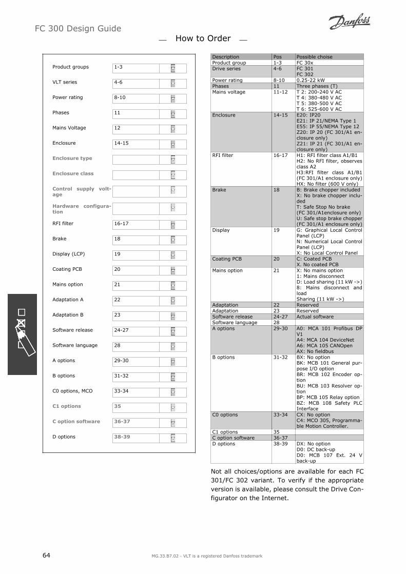
Product groups 1-3
VLT series 4-6
Power rating 8-10
Phases 11
Mains Voltage 12
Enclosure 14-15
Enclosure type
Enclosure class
Control supply volt-
age
Hardware configura-
tion
RFI filter 16-17
Brake 18
Display (LCP) 19
Coating PCB 20
Mains option 21
Adaptation A 22
Adaptation B 23
Software release 24-27
Software language 28
A options 29-30
B options 31-32
C0 options, MCO 33-34
C1 options 35
C option software 36-37
D options 38-39
Description Pos Possible choiseProduct group 1-3 FC 30xDrive series 4-6 FC 301
FC 302Power rating 8-10 0.25-22 kWPhases 11 Three phases (T)Mains voltage 11-12 T 2: 200-240 V AC
T 4: 380-480 V ACT 5: 380-500 V ACT 6: 525-600 V AC
Enclosure 14-15 E20: IP20E21: IP 21/NEMA Type 1E55: IP 55/NEMA Type 12Z20: IP 20 (FC 301/A1 en-closure only)Z21: IP 21 (FC 301/A1 en-closure only)
RFI filter 16-17 H1: RFI filter class A1/B1H2: No RFI filter, observesclass A2H3:RFI filter class A1/B1(FC 301/A1 enclosure only)HX: No filter (600 V only)
Brake 18 B: Brake chopper includedX: No brake chopper inclu-dedT: Safe Stop No brake(FC 301/A1enclosure only)U: Safe stop brake chopper(FC 301/A1 enclosure only)
Display 19 G: Graphical Local ControlPanel (LCP)N: Numerical Local ControlPanel (LCP)X: No Local Control Panel
Coating PCB 20 C: Coated PCBX. No coated PCB
Mains option 21 X: No mains option1: Mains disconnectD: Load sharing (11 kW ->)8: Mains disconnect andloadSharing (11 kW ->)
Adaptation 22 ReservedAdaptation 23 ReservedSoftware release 24-27 Actual softwareSoftware language 28 A options 29-30 A0: MCA 101 Profibus DP
V1A4: MCA 104 DeviceNetA6: MCA 105 CANOpenAX: No fieldbus
B options 31-32 BX: No optionBK: MCB 101 General pur-pose I/O optionBR: MCB 102 Encoder op-tionBU: MCB 103 Resolver op-tionBP: MCB 105 Relay optionBZ: MCB 108 Safety PLCInterface
C0 options 33-34 CX: No optionC4: MCO 305, Programma-ble Motion Controller.
C1 options 35 C option software 36-37D options 38-39 DX: No option
D0: DC back-upD0: MCB 107 Ext. 24 Vback-up
Not all choices/options are available for each FC301/FC 302 variant. To verify if the appropriateversion is available, please consult the Drive Con-figurator on the Internet.
FC 300 Design Guide How to Order
64 MG.33.B7.02 - VLT is a registered Danfoss trademark

Ordering Numbers: Options and Accessories
Type Description Ordering no.Miscellaneous hardwareDC link connector Terminal block for DC link connnection on frame size A2/A3 130B1064 IP 21/4X top/TYPE 1 kit Enclosure, frame size A1: IP21/IP 4X Top/TYPE 1 130BIP 21/4X top/TYPE 1 kit Enclosure, frame size A2: IP21/IP 4X Top/TYPE 1 130B1122 IP 21/4X top/TYPE 1 kit Enclosure, frame size A3: IP21/IP 4X Top/TYPE 1 130B1123Profibus D-Sub 9 Connector kit for IP20 130B1112 Profibus top entry kit Top entry kit for Profibus connection 130B05241)
Terminal blocks Screw terminal blocks for replacing spring loaded terminals1 pc 10 pin 1 pc 6 pin and 1 pc 3 pin connectors 130B1116
Footmount frame for flat pack resistors, frame size A2 175U0085Footmount frame for flat pack resistors, frame size A3 175U0088 Footmount frame for 2 flat pack resistors, frame size A2 175U0087Footmount frame for 2 flat pack resistors, frame size A3 175U0086 LCPLCP 101 Numerical Local Control Panel (NLCP) 130B1124LCP 102 Graphical Local Control Panel (GLCP) 130B1107 LCP cable Separate LCP cable, 3 m 175Z0929LCP kit Panel mounting kit including graphical LCP, fasteners, 3 m cable
and gasket130B1113
LCP kit Panel mounting kit including numerical LCP, fasteners and gasket 130B1114LCP kit Panel mounting kit for all LCPs including fasteners, 3 m cable and
gasket130B1117
Options for Slot A Uncoated CoatedMCA 101 Profibus option DP V0/V1 130B1100 130B1200MCA 104 DeviceNet option 130B1102 130B1202MCA 105 CANopen 130B1103 130B1205Options for Slot BMCB 101 General purpose Input Output option 130B1125 130B1212MCB 102 Encoder option 130B1115 130B1203MCB 103 Resolver option 130B1127 130B1227MCB 105 Relay option 130B1110 130B1210MCB 108 Safety PLC interface (DC/DC Converter) 130B1120 130B1220
Options for Slot CMCO 305 Programmable Motion Controller 130B1134 130B1234Mounting kit for frame size A2 and A3 130B7530 -Mounting kit for frame size A5 130B7532 -Mounting kit for frame size B and C 130B7533 -Option for Slot DMCB 107 24 V DC back-up 130B1108 130B1208External OptionsEthernet IP Ethernet master 175N2584 -Spare PartsControl board FC 302 Coated version - 130B1109Control board FC 301 Coated version - 130B1126Fan A2 Fan, frame size A2 130B1009 -Fan A3 Fan, frame size A3 130B1010 -Fan option C 130B7534 -Backplate A5 Backplate A5 enclosures for 130B1098Connectors FC 300 Profibus 10 pieces Profibus connectors 130B1075 Connectors FC 300 DeviceNet 10 pieces DeviceNet connectors 130B1074Connectors FC 302 10 pole 10 pieces 10 pole spring loaded connectors 130B1073 Connectors FC 301 8 pole 10 pieces 8 pole spring loaded connectors 130B1072Connectors FC 300 5 pole 10 pieces 5 pole spring loaded connectors 130B1071 Connectors FC 300 RS485 10 pieces 3 pole spring loaded connectors for RS 485 130B1070Connectors FC 300 3 pole 10 pieces 3 pole connectors for relay 01 130B1069 Connectors FC 302 3 pole 10 pieces 3 pole connectors for relay 02 130B1068Connectors FC 300 Mains 10 pieces mains connectors IP20/21 130B1067 Connectors FC 300 Mains 10 pieces mains connctors IP 55 130B1066Connectors FC 300 Motor 10 pieces motor connectors 130B1065 Connectors FC 300 Brake DCbus
10 pieces brake/load sharing connectors 130B1073
Accessory bag A1 Accessory bag, frame size A1 130B1021 Accessory bag A5 Accessory bag, frame size A5 (IP55) 130B1023Accessory bag A2 Accessory bag, frame size A2/A3 130B1022 Accessory bag B1 Accessory bag, frame size B1 130B1024Accessory bag B2 Accessory bag, frame size B2 130B1025 Accessory bag MCO 305 130B75351) Only IP21 / > 11 kW
Options can be ordered as factory built-in options, see ordering information. For information on fieldbus and application optioncombatibility with older software versions , please contact your Danfoss supplier.
FC 300 Design Guide How to Order
MG.33.B7.02 - VLT is a registered Danfoss trademark 65

Ord
eri
ng
Nu
mb
ers
: B
rake R
esi
sto
rsM
ain
s 2
00
-24
0 V
FC 3
01/3
02
Sel
ecte
d r
esis
tor
Sta
ndar
d I
P 2
0Alu
min
ium
House
d (
Flat
pac
k) I
P65
Max
. to
rque
load
bD
uty
Cyc
le 1
0%
Duty
Cyc
le 4
0%
FC 3
01/
FC 3
02
P mot
or
Rm
inR
br,
nom c
Rre
cP b
r m
axO
rder
no.
Rre
cP b
r m
axO
rder
no.
Rre
c per
item
Duty
cyc
leO
rder
no.
FC 3
01
FC 3
02
[k
W]
[Ω]
[Ω]
[Ω]
[kW
]175U
xxxx
[Ω]
[kW
]175U
xxxx
[Ω]
%175U
xxxx
PK25
0.2
5420
466.7
425
0.0
95
1841
425
0.4
30
1941
430Ω
/100W
81002
145%
160%
PK37
0.3
7284
315.3
310
0.2
50
1842
310
0.8
00
1942
310Ω
/200W
16
0984
145%
160%
PK55
0.5
5190
211.0
210
0.2
85
1843
210
1.3
50
1943
210Ω
/200W
90987
145%
160%
PK75
0.7
5139
154.0
145
0.0
65
1820
145
0.2
60
1920
150Ω
/100W
14
1005
145%
160%
PK75
0.7
5139
154.0
--
--
--
150Ω
/200W
40
0989
145%
160%
P1K1
1.1
90
104.4
90
0.0
95
1821
90
0.4
30
1921
100Ω
/100W
81006
145%
160%
P1K1
1.1
90
104.4
--
--
--
100Ω
/200W
20
0991
145%
160%
P1K5
1.5
65
75.7
65
0.2
50
1822
65
0.8
00
1922
72Ω
/200W
16
0992
145%
160%
P2K2
2.2
46
51.0
50
0.2
85
1823
50
1.0
01923
50Ω
/200W
90993
145%
160%
P3K0
333
37.0
35
0.4
30
1824
35
1.3
51924
35Ω
/200W
5.5
0994
145%
160%
P3K0
333
37.0
--
--
--
72Ω
/200W
12
2X0992
a145%
160%
P3K7
3.7
25
29.6
25
0.8
00
1825
25
3.0
01925
60Ω
/200W
13
2X0996
a145%
160%
a O
rder
tw
o p
iece
s, r
esis
tors
must
be
connec
ted in p
aral
lel.
b M
ax.
load
with t
he
resi
stor
in D
anfo
ss s
tandar
d p
rogra
m.
c R
br,
nom is
the
nom
inal
(re
com
men
ded
) re
sist
or
valu
e th
at e
nsu
res
a bra
ke p
ow
er o
n m
otor
shaf
t of 145%
/ 1
60%
for
1 m
inute
.
FC 300 Design Guide How to Order
66 MG.33.B7.02 - VLT is a registered Danfoss trademark

Ord
eri
ng
Nu
mb
ers
: B
rake R
esi
sto
rsM
ain
s 3
80
-50
0 V
/ 3
80
-48
0 V
FC 3
01/3
02
Sel
ecte
d r
esis
tor
Sta
ndar
d I
P 2
0Alu
min
ium
House
d (
Flat
pac
k) I
P65
Max
. to
rque
load
bD
uty
Cyc
le 1
0%
Duty
Cyc
le 4
0%
FC 3
01/
FC 3
02
P mot
or
Rm
inR
br,
nom c
Rre
cP b
r m
axO
rder
no.
Rre
cP b
r m
axO
rder
no.
Rre
c per
item
Duty
cyc
leO
rder
no.
FC 3
01
FC 3
02
[k
W]
[Ω]
[Ω]
[Ω]
[kW
]175U
xxxx
[Ω]
[kW
]175U
xxxx
[Ω]
%175U
xxxx
PK37
0.3
7620
1360.2
620
0.0
65
1840
830
0.4
50
1976
830Ω
/100W
20
1000
137%
160%
PK55
0.5
5620
915.0
620
0.0
65
1840
830
0.4
50
1976
830Ω
/100W
20
1000
137%
160%
PK75
0.7
5601
667.6
620
0.0
65
1840
620
0.2
60
1940
620Ω
/100W
14
1001
137%
160%
PK75
0.7
5601
667.6
--
--
--
620Ω
/200W
40
0982
137%
160%
P1K1
1.1
408
452.8
425
0.0
95
1841
425
0.4
30
1941
430Ω
/100W
81002
137%
160%
P1K1
1.1
408
452.8
--
--
--
430Ω
/200W
20
0983
137%
160%
P1K5
1.5
297
330.4
310
0.2
50
1842
310
0.8
00
1942
310Ω
/200W
16
0984
137%
160%
P2K2
2.2
200
222.6
210
0.2
85
1843
210
1.3
51943
210Ω
/200W
90987
137%
160%
P3K0
3145
161.4
150
0.4
30
1844
150
2.0
01944
150Ω
/200W
5.5
0989
137%
160%
P3K0
3145
161.4
--
--
--
300Ω
/200W
12
2X0985
a137%
160%
P4K0
4108
119.6
110
0.6
00
1845
110
2.4
01945
240Ω
/200W
11
2X0986
a137%
160%
P5K5
5.5
77
86.0
80
0.8
50
1846
80
3.0
01946
160Ω
/200W
6.5
2X0988
a137%
160%
P7K5
7.5
56
62.4
65
1.0
1847
65
4.5
01947
130Ω
/200W
42X0990
a137%
160%
P11K
11
38
42.1
40
1.8
1848
40
5.0
01948
80Ω
/240W
92X0090
a137%
160%
P15K
15
27
30.5
30
2.8
1849
30
9.3
01949
72Ω
/240W
62X0091
a137%
160%
P18K
18.5
22
24.5
25
3.5
1850
25
12.7
01950
P2
2K
22
18
20.3
20
4.0
1851
20
13.0
01951
a O
rder
tw
o p
iece
s, r
esis
tors
must
be
connec
ted in p
aral
lel.
b M
ax.
load
with t
he
resi
stor
in D
anfo
ss s
tandar
d p
rogra
m.
c R
br,
nom is
the
nom
inal
(re
com
men
ded
) re
sist
or
valu
e th
at e
nsu
res
a bra
ke p
ow
er o
n m
otor
shaf
t of 137%
/ 1
60%
for
1 m
inute
.
FC 300 Design Guide How to Order
MG.33.B7.02 - VLT is a registered Danfoss trademark 67

Ordering Numbers: Harmonic Filters
Harmonic filters are used to reduce mains harmonics.
AHF 010: 10% current distortion
AHF 005: 5% current distortion
380-415V, 50HzIAHF,N Typical Motor Used [kW] Danfoss ordering number FC 301/ FC 302
AHF 005 AHF 01010 A 4, 5.5 175G6600 175G6622 P4K0, P5K519 A 7.5 175G6601 175G6623 P7K546 A 11 175G6602 175G6624 P11K35 A 15, 18.5 175G6603 175G6625 P15K, P18K43 A 22 175G6604 175G6626 P22K
440-480V, 60HzIAHF,N Typical Motor Used
[HP]Danfoss ordering number FC 301/ FC 302
AHF 005 AHF 01019 A 10, 15 175G6612 175G6634 P7K526 A 20 175G6613 175G6635 P15K35 A 25, 30 175G6614 175G6636 P18K, P22K
500V, 50HzIAHF,N Typical Motor Used
[kW]Danfoss ordering number FC 301/ FC 302
AHF 005 AHF 01010 A 4, 5.5 175G6644 175G6656 P4K0, P5K519 A 7.5, 11 175G6645 175G6634 P7K5, P11K26 A 15, 18.5 175G6646 175G6635 P15K, P18K35 A 22 175G6647 175G6636 P22K
Matching the frequency converter and filter is pre-calculated based on 400V/480V and on a typical motorload (4 pole) and 160 % torque.
Ordering Numbers: LC Filter Modules ,200-240 VAC
Mains supply 3 x 200-240 V
FC 301/ FC 302 LC filter enclosure Rated currentat 200 V
Max. torqueat CT/VT
Max. output fre-quency Ordering no.
PK25 - P1K5 Bookstyle IP 20 7.8 A 160% 120 Hz 175Z0825P2K2 - P3K7 Bookstyle IP 20 15.2 A 160% 120 Hz 175Z0826PK25 - P3K7 Compact IP 20 15.2 A 160% 120 Hz 175Z0832
NB!When using LC filters, the switching frequency must be minimum 4.5 kHz (see par. 14-01).
FC 300 Design Guide How to Order
68 MG.33.B7.02 - VLT is a registered Danfoss trademark

Ordering Numbers: LC Filter Modules,380-500 VAC
Mains supply 3 x 380 - 500 VFC 301/ FC302
LC filterenclosure
Rated current at400/500 V
Max. torqueat CT/VT
Max. outputfrequency
Power dissi-pation
Orderingno.
PK37-P3K0 Bookstyle IP20 7.2 A / 6.3 A 160% 120 Hz - 175Z0825P4K0-P7K5 Bookstyle IP20 16 A / 14.5 A 160% 120 Hz - 175Z0826PK37-P7K5 Compact IP20 16 A / 14.5 A 160% 120 Hz - 175Z0832High overload torqueP11K Compact IP20 24 A / 21.7 A 160% 60 Hz 125 W 175Z4606P15K Compact IP20 32 A / 27.9 A 160% 60 Hz 130 W 175Z4607P18K Compact IP20 37.5 A / 32 A 160% 60 Hz 140 W 175Z4608P22K Compact IP20 44 A / 41.4 A 160% 60 Hz 170 W 175Z4609Normal overload torqueP11K Compact IP20 32 A / 27.9 A 110% 60 Hz 130 W 175Z4607P15K Compact IP20 37.5 A / 32 A 110% 60 Hz 140 W 175Z4608P18K Compact IP20 44 A / 41.4 A 110% 60 Hz 170 W 175Z4609P22K Compact IP20 61 A / 54 A 110% 60 Hz 250 W 175Z4610
LC filters for FC 300, 525 - 600 V, please contact Danfoss.
NB!When using LC filters, the switching frequency must be minimum 4.5 kHz (see par. 14-01).
FC 300 Design Guide How to Order
MG.33.B7.02 - VLT is a registered Danfoss trademark 69

FC 300 Design Guide
70 MG.33.B7.02 - VLT is a registered Danfoss trademark

How to Install
Mechanical Dimension
FC 300 Design Guide How to Install
MG.33.B7.02 - VLT is a registered Danfoss trademark 71
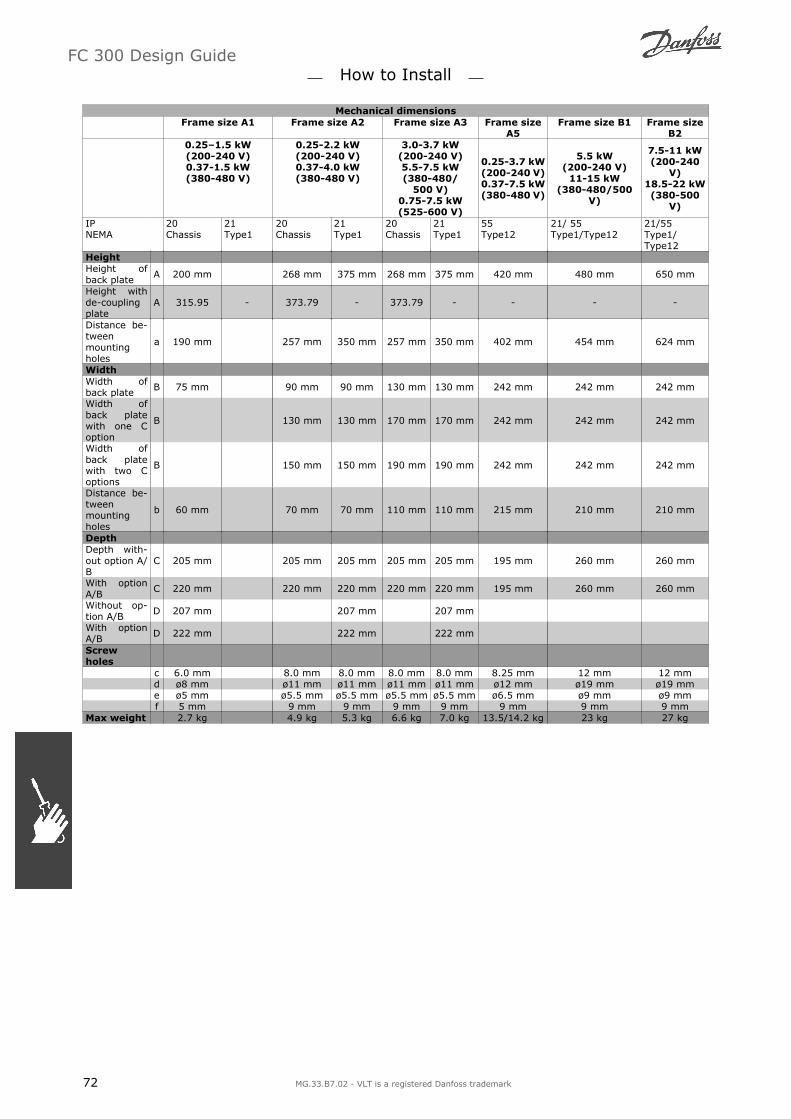
Mechanical dimensionsFrame size A1 Frame size A2 Frame size A3 Frame size
A5Frame size B1 Frame size
B20.251.5 kW(200-240 V)0.37-1.5 kW(380-480 V)
0.25-2.2 kW(200-240 V)0.37-4.0 kW(380-480 V)
3.0-3.7 kW(200-240 V)5.5-7.5 kW(380-480/
500 V)0.75-7.5 kW(525-600 V)
0.25-3.7 kW(200-240 V)0.37-7.5 kW(380-480 V)
5.5 kW(200-240 V)
11-15 kW(380-480/500
V)
7.5-11 kW(200-240
V)18.5-22 kW(380-500
V)
IPNEMA
20Chassis
21Type1
20Chassis
21Type1
20Chassis
21Type1
55Type12
21/ 55Type1/Type12
21/55Type1/Type12
HeightHeight ofback plate A 200 mm 268 mm 375 mm 268 mm 375 mm 420 mm 480 mm 650 mm
Height withde-couplingplate
A 315.95 - 373.79 - 373.79 - - - -
Distance be-tweenmountingholes
a 190 mm 257 mm 350 mm 257 mm 350 mm 402 mm 454 mm 624 mm
WidthWidth ofback plate B 75 mm 90 mm 90 mm 130 mm 130 mm 242 mm 242 mm 242 mm
Width ofback platewith one Coption
B 130 mm 130 mm 170 mm 170 mm 242 mm 242 mm 242 mm
Width ofback platewith two Coptions
B 150 mm 150 mm 190 mm 190 mm 242 mm 242 mm 242 mm
Distance be-tweenmountingholes
b 60 mm 70 mm 70 mm 110 mm 110 mm 215 mm 210 mm 210 mm
DepthDepth with-out option A/B
C 205 mm 205 mm 205 mm 205 mm 205 mm 195 mm 260 mm 260 mm
With optionA/B C 220 mm 220 mm 220 mm 220 mm 220 mm 195 mm 260 mm 260 mm
Without op-tion A/B D 207 mm 207 mm 207 mm
With optionA/B D 222 mm 222 mm 222 mm
Screwholes
c 6.0 mm 8.0 mm 8.0 mm 8.0 mm 8.0 mm 8.25 mm 12 mm 12 mmd ø8 mm ø11 mm ø11 mm ø11 mm ø11 mm ø12 mm ø19 mm ø19 mme ø5 mm ø5.5 mm ø5.5 mm ø5.5 mm ø5.5 mm ø6.5 mm ø9 mm ø9 mmf 5 mm 9 mm 9 mm 9 mm 9 mm 9 mm 9 mm 9 mm
Max weight 2.7 kg 4.9 kg 5.3 kg 6.6 kg 7.0 kg 13.5/14.2 kg 23 kg 27 kg
FC 300 Design Guide How to Install
72 MG.33.B7.02 - VLT is a registered Danfoss trademark

Mechanical Installation
Accessory Bag
Find the following parts included in the FC 300 Ac-cessory Bag.
FC 301/FC 302Frame sizes A1, A2 and A3IP20/Chassis
FC 301/FC 302Frame size A5IP55/Type12
FC 301/FC 302Frame sizes B1 and B2IP21/IP55/Type1/Type12
1 + 2 only available in units with brake chopper FC 301 without Safe Stop. Only one relay connectoris included for FC 301 units. For DC link connection (Load sharing) the connector 1 can be orderedseparately (Code no 130B1064)
An eight pole connector included in accessory bag for FC 301 without Safe Stop.
FC 300 Design Guide How to Install
MG.33.B7.02 - VLT is a registered Danfoss trademark 73

Mechanical mounting
FC 300 IP20 Frame sizes A1, A2 and A3 allows side-by-side installation . Due to cooling conditions ,there must be a minimum of 100 mm free air passage above and below the FC 300.
B1 and B2 enclosures allow side-by-side installa-tion.
If the IP 21 Enclosure kit (130B1122 or130B1123) is used there must be a clearance be-tween the drives of min 50 mm.
1. Drill holes in accordance with the measurements given.
2. You must provide screws suitable for the surface on which you want to mount the FC 300. Re-tighten all four screws.
Mounting frame sizes A1, A2 and A3:
FC 300 Design Guide How to Install
74 MG.33.B7.02 - VLT is a registered Danfoss trademark

Mounting frame sizes A5, B1 and B2: The back wall must always be solid for optimumcooling.
Mounting frame sizes A5, B1, and B2 on a nonesolid back wall, the drive must be provided with a
back plate A due to insufficient cooling air over theheat sink.
Safety Requirements of Mechanical Instal-lation
Pay attention to the requirements that apply to integration and field mounting kit. Observethe information in the list to avoid serious damage or injury, especially when installing largeunits.
The frequency converter is cooled by means of air circulation.To protect the unit from overheating, it must be ensured that the ambient temperature does not exceedthe maximum temperature stated for the frequency converter and that the 24-hour average temperatureis not exceeded. Locate the maximum temperature and 24-hour average in the paragraph Derating forAmbient Temperature.If the ambient temperature is in the range of 45 °C - 55 ° C, derating of the frequency converter willbecome relevant, see Derating for Ambient Temperature.The service life of the frequency converter is reduced if derating for ambient temperature is not takeninto account.
Field Mounting
For field mounting the IP 21/IP 4X top/TYPE 1 kits or IP 54/55 units are recommended.
FC 300 Design Guide How to Install
MG.33.B7.02 - VLT is a registered Danfoss trademark 75

Electrical Installation
NB!Cables GeneralAll cabling must comply with national and local regulations on cable cross-sections and am-bient temperature. Copper (60/75°C) conductors recommended.
Aluminium ConductorsAluminium conductors are not recommended.Terminals can accept aluminium conductors butthe conductor surface has to be clean and the ox-idation must be removed and sealed by neutalacid free Vaseline grease before the conductor isconnected.
Furthermore the terminal screw must be retight-ened after two days due to softness of the alumi-nium. It is crucial to keep the connection a gastight joint, otherwise the aluminium surface willoxidize again.
Tightening-up TorqueFC size Cable for: Tightening up torque0.25-7.5 kW (A1, A2, A3and A5)
Line, Brake resistor, load sharing, Motor ca-bles
0.5-0.6 Nm
11-15 kW (B1) Line, Brake resistor, load sharing, Motor ca-bles
1.8 Nm
Relay 0.5-0.6 NmEarth 2-3 Nm
18.5-22 kW (B2) Line, Brake resistor, load sharing cables 1.8 NmMotor cables 1.8 NmRelay 0.5-0.6 NmEarth 2-3 Nm
Removal of Knockouts for Extra Cables
1. Remove cable entry from the frequency converter (Avoiding foreign parts falling into the fre-quency converter when removing knockouts)
2. Cable entry has to be supported around the knockout you intend to remove.
3. The knockout can now be removed with a strong mandrel and a hammer.
4. Remove burrs from the hole.
5. Mount Cable entry on frequency converter.
FC 300 Design Guide How to Install
76 MG.33.B7.02 - VLT is a registered Danfoss trademark

Connection to Mains and Earthing
NB!The plug connector for power can beremoved on FC 302 up to 7.5 kW.
1. Fit the two screws in the de-couplingplate, slide it into place and tighten thescrews.
2. Make sure the FC 300 is properly earthed.Connect to earth connection (terminal95). Use screw from the accessory bag.
3. Place plug connector 91(L1), 92(L2), 93(L3) from the accessory bag onto the ter-minals labelled MAINS at the bottom of FC300.
4. Attach mains wires to the mains plug con-nector.
5. Relive the cable with the supporting en-closed brackets.
NB!Check that mains voltage correspondsto the mains voltage of the FC 300name plate.
IT MainsDo not connect 400 V frequency con-verters with RFI-filters to mains sup-plies with a voltage between phaseand earth of more than 440 V.
The earth connection cable cross sec-
tion must be at least 10 mm2 or 2 xrated mains wires terminated sepa-rately according to EN 50178.
The mains connection is fitted to the main switchif this is included.
FC 300 Design Guide How to Install
MG.33.B7.02 - VLT is a registered Danfoss trademark 77

Mains connection for A1, A2 and A3 frame sizes:NB!The plug connector for power can beremoved.
Mains connector A5 (IP 55 ) Enclosure
When disconnector is used (A5 enclosure) the PE must be mounted on the left side of the drive.
Mains connection B1 and B2 (IP 21/NEMA Type1and IP 55/NEMA Type12) Enclosures
Usually the power cables for mains are unshielded ca-bles.
FC 300 Design Guide How to Install
78 MG.33.B7.02 - VLT is a registered Danfoss trademark

Motor Connection
NB!Motor cable must be screened/arm-oured. If an unscreened/unarmouredcable is used, some EMC requirementsare not complied with. For more infor-mation, see EMC specifications in theVLT AutomationDrive FC 300 DesignGuide.
See section General Specifications for correct di-mensioning of motor cable cross-section andlength.
Use a screened/armoured motor cable tocomply with EMC emission specifications.If an unscreened/unarmoured cable isused, some EMC requirements are notcomplied with. For more information, seeEMC specifications in the VLT Automation-Drive FC 300 Design Guide.
Keep the motor cable as short as possibleto reduce the noise level and leakage cur-rents.
Connect the motor cable screen to boththe decoupling plate of the FC 300 and tothe metal housing of the motor.
Make the screen connections with thelargest possible surface area (cableclamp). This is done by using the suppliedinstallation devices in the FC 300.
Screening of cables: Avoid installationwith twisted screen ends (pigtails). Theyspoil the screening effect at higher fre-quencies. If it is necessary to break thescreen to install a motor isolator or motorcontactor, the screen must be continuedat the lowest possible HF impedance.
If it is necessary to split the screen to in-stall a motor isolator or motor relay, thescreen must be continued with the lowestpossible HF impedance.
Screening of cables: Avoid installation withtwisted screen ends (pigtails). They spoil thescreening effect at higher frequencies. If it is nec-essary to break the screen to install a motor iso-lator or motor contactor, the screen must becontinued at the lowest possible HF impedance.
Cable-length and cross-section: The frequen-cy converter has been tested with a given lengthof cable and a given cross-section of that cable. Ifthe cross-section is increased, the cable capaci-tance - and thus the leakage current - may in-crease, and the cable length must be reducedcorrespondingly.
Switching frequency: When frequency convert-ers are used together with LC filters to reduce theacoustic noise from a motor, the switching fre-quency must be set according to the LC filter in-struction in Par. 14-01.
1. Fasten decoupling plate to the bottom ofFC 300 with screws and washers from theaccessory bag.
2. Attach motor cable to terminals 96 (U), 97(V), 98 (W).
3. Connect to earth connection (terminal 99)on decoupling plate with screws from theaccessory bag.
4. Insert plug connectors 96 (U), 97 (V), 98(W) (up to 7.5 kW) and motor cable toterminals labelled MOTOR.
5. Fasten screened cable to decoupling platewith screws and washers from the acces-sory bag.
Motor connection ≤ 7.5 kW IP 20 (A1, A2 and A3 enclo-sures)
FC 300 Design Guide How to Install
MG.33.B7.02 - VLT is a registered Danfoss trademark 79

Motor connection ≤ 7.5 kW IP 55 / NEMA type 12
Motor connection 11-22 kW IP 21 / NEMA type 1, IP55 /NEMA type 12 (B1 and B2 enclosures)
All types of three-phase asynchronous standardmotors can be connected to the FC 300. Normally,small motors are star-connected (230/400 V, Δ/
Y). Large motors are normally delta-connected(400/690 V, Δ/Y). Refer to the motor name platefor correct connection mode and voltage.
No. 96 97 98 99 U V W PE1) Motor voltage 0-100% of mains voltage.
3 wires out of motor U1 V1 W1
PE1) Delta-connectedW2 U2 V2 6 wires out of motor
U1 V1 W1 PE1) Star-connected U2, V2, W2U2, V2 and W2 to be interconnected separately.
1)Protected Earth Connection
NB!In motors without phase insulation paper or other insulation reinforcement suitable for oper-ation with voltage supply (such as a frequency converter), fit an LC filter on the output ofthe FC 300.
FC 300 Design Guide How to Install
80 MG.33.B7.02 - VLT is a registered Danfoss trademark

Fuses
Branch circuit protection:In order to protect the installation against electrical and fire hazard, all branch circuits in an installation,switch gear, machines etc., must be shortcircuit and overcurrent protected according to the national/international regulations.
Short circuit protection :The frequency converter must be protected against short-circuit to avoid electrical or fire hazard. Danfossrecommends using the fuses mentioned below to protect service personnel or other equipment in caseof an internal failure in the drive. The frequency converter provides full short circuit protection in case ofa short-circuit on the motor output.
Over current protection:Provide overload protection to avoid fire hazard due to overheating of the cables in the installation. Thefrequency converter is equipped with an internal over current protection that can be used for upstreamoverload protection (UL-applications excluded). See par. 4-18. Moreover, fuses or circuit breakers canbe used to provide the over current protection in the installation. Over current protection must alwaysbe carried out according to national regulations.
Fuses must be designed for protection in a circuit capable of supplying a maximum of 100,000 Arms
(symmetrical), 500 V maximum.
Non UL compliance
If UL/cUL is not to be complied with, we recom-mend using the following fuses, which will ensurecompliance with EN50178:In case of malfunction, not following the recom-mendation may result in unnecessary damage ofthe frequency converter.
FC 30X Max. fuse size Voltage TypeK25-K75 10A1) 200-240 V type gG1K1-2K2 20A1) 200-240 V type gG3K0-3K7 32A1) 200-240 V type gGK37-1K5 10A1) 380-500 V type gG2K2-4K0 20A1) 380-500 V type gG5K5-7K5 32A1) 380-500 V type gG11K 63A1) 380-500 V type gG15K 63A1) 380-500 V type gG18K 63A1) 380-500 V type gG22K 80A1) 380-500 V type gG
1) Max. fuses - see national/international regula-tions for selecting an applicable fuse size.
UL Compliance
200-240 V
FC 30X Bussmann Bussmann Bussmann SIBA Littel fuse Ferraz-Shawmut
Ferraz-Shawmut
kW Type RK1 Type J Type T Type RK1 Type RK1 Type CC Type RK1K25-K75 KTN-R10 JKS-10 JJN-10 5017906-010 KLN-R10 ATM-R10 A2K-10R1K1-2K2 KTN-R20 JKS-20 JJN-20 5017906-020 KLN-R20 ATM-R20 A2K-20R3K0-3K7 KTN-R30 JKS-30 JJN-30 5012406-032 KLN-R30 ATM-R30 A2K-30R
FC 300 Design Guide How to Install
MG.33.B7.02 - VLT is a registered Danfoss trademark 81

380-500 V, 525-600 V
FC 30X Bussmann Bussmann Bussmann SIBA Littel fuse Ferraz-Shawmut
Ferraz-Shawmut
kW Type RK1 Type J Type T Type RK1 Type RK1 Type CC Type RK1K37-1K5 KTS-R10 JKS-10 JJS-10 5017906-010 KLS-R10 ATM-R10 A6K-10R2K2-4K0 KTS-R20 JKS-20 JJS-20 5017906-020 KLS-R20 ATM-R20 A6K-20R5K5-7K5 KTS-R30 JKS-30 JJS-30 5012406-032 KLS-R30 ATM-R30 A6K-30R11K KTS-R40 JKS-40 JJS-40 5014006-040 KLS-R40 A6K-40R15K KTS-R50 JKS-50 JJS-50 5014006-050 KLS-R50 A6K-50R18K KTS-R60 JKS-60 JJS-60 5014006-063 KLS-R60 A6K-60R22K KTS-R80 JKS-80 JJS-80 5014006-100 KLS-R80 A6K-80R
KTS-fuses from Bussmann may substitute KTN for 240 V frequency converters.
FWH-fuses from Bussmann may substitute FWX for 240 V frequency converters.
KLSR fuses from LITTEL FUSE may substitute KLNR fuses for 240 V frequency converters.
L50S fuses from LITTEL FUSE may substitute L50S fuses for 240 V frequency converters.
A6KR fuses from FERRAZ SHAWMUT may substitute A2KR for 240 V frequency converters.
A50X fuses from FERRAZ SHAWMUT may substitute A25X for 240 V frequency converters.
FC 300 Design Guide How to Install
82 MG.33.B7.02 - VLT is a registered Danfoss trademark

Access to Control Terminals
All terminals to the control cables are located un-derneath the terminal cover on the front of thefrequency converter. Remove the terminal coverby means of a screwdriver (see illustration).
A1, A2 and A3 enclosures
A5, B1 and B2 enclosures
Control Terminals (FC 301)
Drawing reference numbers:
1. 8 pole plug digital I/O.
2. 3 pole plug RS485 Bus.
3. 6 pole analog I/O.
4. USB Connection .
Control Terminals (FC 302)
Drawing reference numbers:
1. 10 pole plug digital I/O.
2. 3 pole plug RS485 Bus.
3. 6 pole analog I/O.
4. USB Connection .
Control terminals (all enclosures)
FC 300 Design Guide How to Install
MG.33.B7.02 - VLT is a registered Danfoss trademark 83

Electrical Installation , Control Terminals
To mount the cable to the terminal:1. Strip isolation of 9-10 mm
2. Insert a screw driver1) in the square hole.
3. Insert the cable in the adjacent circularhole.
4. Remove the screw driver. The cable isnow mounted to the terminal.
To remove the cable from the terminal:1. Insert a screw driver1) in the square hole.
2. Pull out the cable.
1) Max. 0.4 x 2.5 mm
1.
2. 3.
Assembling of IP55 / NEMA TYPE 12 (A5 housing)with mains disconnector
Basic Wiring Example
1. Mount terminals from the accessory bagto the front of the FC 300.
2. Connect terminals 18, 27 and 37 (FC 302only) to +24 V (terminal 12/13)
Default settings:18 = Start, Par 5-10 [9]27 = Stop inverse, Par 5-12 [6]37 = safe stop inverse
FC 300 Design Guide How to Install
84 MG.33.B7.02 - VLT is a registered Danfoss trademark

Electrical Installation , Control Cables
Diagram showing all electrical terminals without options.Terminal 37 is the input to be used for Safe Stop. For instructions on Safe Stop installation please refer to the sectionSafe Stop Installation in the FC 300 Design Guide.* Terminal 37 is not included in FC 301 (Except FC 301 A1, which includes Safe Stop).Terminal 29, Relay 2, is not included in FC 301.
Very long control cables and analog signals may in rare cases and depending on installation result in50/60 Hz earth loops due to noise from mains supply cables.
If this occurs, you may have to break the screen or insert a 100 nF capacitor between screen and chassis.
The digital and analog in- and outputs must be connected separately to the FC 300 common inputs (ter-minal 20, 55, 39) to avoid ground currents from both groups to affect other groups. For example,switching on the digital input may disturb the analog input signal.
FC 300 Design Guide How to Install
MG.33.B7.02 - VLT is a registered Danfoss trademark 85
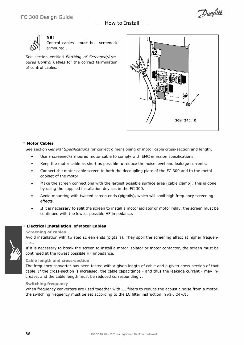
NB!Control cables must be screened/armoured .
See section entitled Earthing of Screened/Arm-oured Control Cables for the correct terminationof control cables.
Motor Cables
See section General Specifications for correct dimensioning of motor cable cross-section and length.
Use a screened/armoured motor cable to comply with EMC emission specifications.
Keep the motor cable as short as possible to reduce the noise level and leakage currents.
Connect the motor cable screen to both the decoupling plate of the FC 300 and to the metalcabinet of the motor.
Make the screen connections with the largest possible surface area (cable clamp). This is doneby using the supplied installation devices in the FC 300.
Avoid mounting with twisted screen ends (pigtails), which will spoil high frequency screeningeffects.
If it is necessary to split the screen to install a motor isolator or motor relay, the screen must becontinued with the lowest possible HF impedance.
Electrical Installation of Motor Cables
Screening of cablesAvoid installation with twisted screen ends (pigtails). They spoil the screening effect at higher frequen-cies.If it is necessary to break the screen to install a motor isolator or motor contactor, the screen must becontinued at the lowest possible HF impedance.
Cable length and cross-sectionThe frequency converter has been tested with a given length of cable and a given cross-section of thatcable. If the cross-section is increased, the cable capacitance - and thus the leakage current - may in-crease, and the cable length must be reduced correspondingly.
Switching frequencyWhen frequency converters are used together with LC filters to reduce the acoustic noise from a motor,the switching frequency must be set according to the LC filter instruction in Par. 14-01.
FC 300 Design Guide How to Install
86 MG.33.B7.02 - VLT is a registered Danfoss trademark

Aluminium conductorsAluminium conductors are not recommended. Terminals can accept aluminium conductors but the con-ductor surface has to be clean and the oxidation must be removed and sealed by neutral acid free Vaselinegrease before the conductor is connected.Furthermore, the terminal screw must be retightened after two days due to the softness of the aluminium.It is crucial to keep the connection a gas tight joint, otherwise the aluminium surface will oxidize again.
Switches S201, S202, and S801
Switches S201 (A53) and S202 (A54) are used toselect a current (0-20 mA) or a voltage (-10 to 10V) configuration of the analog input terminals 53and 54 respectively.
Switch S801 (BUS TER.) can be used to enabletermination on the RS-485 port (terminals 68 and69).
See drawing Diagram showing all electrical termi-nals in section Electrical Installation.
Default setting:S201 (A53) = OFF (voltage input)
S202 (A54) = OFF (voltage input)
S801 (Bus termination) = OFF
When changing the function of S201,S202 or S801 be careful not to useforce for the switch over. It is recom-mended to remove the LCP fixture(cradle) when operating the switches.The switches must not be operatedwith power on the frequency convert-er.
FC 300 Design Guide How to Install
MG.33.B7.02 - VLT is a registered Danfoss trademark 87

Final Set-Up and Test
To test the set-up and ensure that the frequency converter is running, follow these steps.
Step 1. Locate the motor name plate .
NB!The motor is either star- (Y) or delta-connected (∆). This information is lo-cated on the motor name plate data .
Step 2. Enter the motor name plate data inthis parameter list.To access this list first press the [QUICK MENU]key then select Q2 Quick Setup.
1. Motor Power [kW]or Motor Power [HP]
par. 1-20par. 1-21
2. Motor Voltage par. 1-223. Motor Frequency par. 1-234. Motor Current par. 1-245. Motor Nominal Speed par. 1-25
Step 3. Activate the Automatic Motor Adaptation (AMA)Performing an AMA will ensure optimum performance. The AMA measures the values from the motormodel equivalent diagram.
1. Connect terminal 37 to terminal 12 (if terminal 37 is available).
2. Connect terminal 27 to terminal 12 or set par. 5-12 to 'No function' (par. 5-12 [0])
3. Activate the AMA par. 1-29.
4. Choose between complete or reduced AMA. If an LC filter is mounted, run only the reduced AMA,or remove the LC filter during the AMA procedure.
5. Press the [OK] key. The display shows Press [Hand on] to start.
6. Press the [Hand on] key. A progress bar indicates if the AMA is in progress.
Stop the AMA during operation
1. Press the [OFF] key - the frequency converter enters into alarm mode and the display shows thatthe AMA was terminated by the user.
FC 300 Design Guide How to Install
88 MG.33.B7.02 - VLT is a registered Danfoss trademark

Successful AMA
1. The display shows Press [OK] to finish AMA.
2. Press the [OK] key to exit the AMA state.
Unsuccessful AMA
1. The frequency converter enters into alarm mode. A description of the alarm can be found in theTroubleshooting section.
2. "Report Value in the [Alarm Log] shows the last measuring sequence carried out by the AMA,before the frequency converter entered alarm mode. This number along with the description ofthe alarm will assist you in troubleshooting. If you contact Danfoss Service, make sure to mentionnumber and alarm description.
NB!Unsuccessful AMA is often caused by incorrectly registered motor name plate data or too bigdifference between the motor power size and the FC 300 power size.
Step 4. Set speed limit and ramp time
Set up the desired limits for speed and ramp time. Minimum Reference par. 3-02Maximum Reference par. 3-03
Motor Speed Low Limit par. 4-11 or 4-12Motor Speed High Limit par. 4-13 or 4-14
Ramp-up Time 1 [s] par. 3-41Ramp-down Time 1 [s] par. 3-42
FC 300 Design Guide How to Install
MG.33.B7.02 - VLT is a registered Danfoss trademark 89

Additional Connections
Load Sharing
With load sharing you can connect several frequency converter's DC intermediate circuit s if you extendthe installation using extra fuses and AC coils (see illustration).
NB!Load sharing cables must be screened/armoured. If an unscreened/unarmoured cable is used,some EMC requirements are not complied with.
Voltage levels of up to 975 V DC mayoccur between terminals 88 and 89.
No. 88 89 Load sharing DC - DC +
Installation of Load sharing
The connection cable must be screened and the max. length from the frequency converter to the DC baris 25 metres.
NB!Load sharing calls for extra equipment and safety considerations. For further information, seeLoad sharing Instructions MI.50.NX.YY.
Brake Connection Option
The connection cable to the brake resistor must bescreened/armoured.
No.
81 82 Brake resistor
R- R+ terminals
NB!Dynamic brake calls for extra equipment and safety considerations. For further information,see the Instruction Brake Resistors for Horizontal Applications, MI50SXYY.
1. Use cable clamps to connect the screen to the metal cabinet of the frequency converter and tothe decoupling plate of the brake resistor.
2. Dimension the cross-section of the brake cable to match the brake current.
NB!Voltages up to 975 V DC (@ 600 V AC) may occur between the terminals.
FC 300 Design Guide How to Install
90 MG.33.B7.02 - VLT is a registered Danfoss trademark

NB!If a short circuit in the brake IGBT occurs, prevent power dissipation in the brake resistor byusing a mains switch or contactor to disconnect the mains for the frequency converter. Onlythe frequency converter shall control the contactor.
Relay Connection
To set relay output, see par. group 5-4* Relays. No. 01 - 02 make (normally open) 01 - 03 break (normally closed) 04 - 05 make (normally open) 04 - 06 break (normally closed)
Terminals for relay connection (≤ 7.5 kW)(A1, A2 and A3 enclosures).
Terminals for relay connection (11-22 kW)(A5, B1 and B2 enclosures).
FC 300 Design Guide How to Install
MG.33.B7.02 - VLT is a registered Danfoss trademark 91

Relay Output
Relay 1
Terminal 01: common
Terminal 02: normal open 240 V AC
Terminal 03: normal closed 240 V AC
Relay 2 (Not FC 301 ≤7.5 kW)
Terminal 04: common
Terminal 05: normal open 400 V AC
Terminal 06: normal closed 240 V AC
Relay 1 and relay 2 are programmed in par. 5-40,5-41, and 5-42.
Additional relay outputs by using option moduleMCB 105.
Parallel Connection of Motors
The frequency converter can control several par-allel-connected motors. The total current con-sumption of the motors must not exceed the ratedoutput current IINV for the frequency converter.This is only recommended when U/f is selected inpar. 1-01.
NB!Installations with cables connected ina common joint as in illustration 1 isonly recommended for short cablelengths.
NB!When motors are connected in paral-lel, par. 1-02 Automatic Motor Adap-tation (AMA) cannot be used, and par.1-01 Motor Control Principle must beset to Special motor characteristics(U/f).
Problems may arise at start and at low RPM values if motor sizes are widely different because smallmotors' relatively high ohmic resistance in the stator calls for a higher voltage at start and at low RPMvalues.
The electronic thermal relay ( ETR ) of the frequency converter cannot be used as motor protection forthe individual motor of SYSTEMs with parallel-connected motors. Provide further motor protection by e.g.thermistors in each motor or individual thermal relays. (Circuit breakers are not suitable as protection).
FC 300 Design Guide How to Install
92 MG.33.B7.02 - VLT is a registered Danfoss trademark

Direction of Motor Rotation
The default setting is clockwise rotation with thefrequency converter output connected as follows.
Terminal 96 connected to U-phaseTerminal 97 connected to V-phaseTerminal 98 connected to W-phase
The direction of motor rotation is changed byswitching two motor phases.
Motor Thermal Protection
The electronic thermal relay in FC 300 has received the UL-approval for single motor protection, whenpar. 1-90 Motor Thermal Protection is set for ETR Trip and par. 1-24 Motor current, IM,N is set to therated motor current (see motor name plate).
Installation of Brake Cable
(Only for frequency converters ordered with brake chopper option).
The connection cable to the brake resistor must be screened.
1. Connect the screen by means of cableclamps to the conductive back plate onthe frequency converter and to the metalcabinet of the brake resistor.
2. Size the brake cable cross-section tomatch the brake torque.
No. Function81, 82 Brake resistor terminals
See Brake instructions, MI.90.FX.YY and MI.50.SX.YY for more information about safe installation.
NB!Voltages up to 960 V DC, depending on the supply voltage, may occur on the terminals.
RS 485 Bus Connection
One or more frequency converters can be connec-ted to a control (or master) using the RS485standardized interface. Terminal 68 is connectedto the P signal (TX+, RX+), while terminal 69 isconnected to the N signal (TX-,RX-).
If more than one frequency converter is connec-ted to a master, use parallel connections.
FC 300 Design Guide How to Install
MG.33.B7.02 - VLT is a registered Danfoss trademark 93

In order to avoid potential equalizing currents in the screen, earth the cable screen via terminal 61, whichis connected to the frame via an RC-link.
Bus terminationThe RS485 bus must be terminated by a resistor network at both ends. For this purpose, set switch S801on the control card for "ON".For more information, see the paragraph Switches S201, S202, and S801.
NB!Communication protocol must be set to FC MC par. 8-30.
How to Connect a PC to the FC 300
To control the frequency converter from a PC, in-stall the MCT 10 Set-up Software.The PC is connected via a standard (host/device)USB cable, or via the RS485 interface as shown inthe section Bus Connection in the chapter How toProgramme.
NB!The USB connection is galvanically iso-lated from the supply voltage (PELV)and other high-voltage terminals. TheUSB connection is connected to pro-tection earth on the frequency con-verter. Use only isolated laptop as PCconnection to the USB connector onthe FC 300 drive.
USB connection.
The FC 300 Software Dialog
Data storage in PC via MCT 10 Set-Up Soft-ware:
1. Connect a PC to the unit via USB com port
2. Open MCT 10 Set-up Software
3. Choose Read from drive
4. Choose Save as
All parameters are now stored.
Data transfer from PC to drive via MCT 10Set-Up Software:
1. Connect a PC to the unit via USB com port
2. Open MCT 10 Set-up software
3. Choose Open stored files will be shown
4. Open the appropriate file
5. Choose Write to drive
All parameters are now transferred to the drive.
A separate manual for MCT 10 Set-up Software isavailable.
FC 300 Design Guide How to Install
94 MG.33.B7.02 - VLT is a registered Danfoss trademark

High Voltage Test
Carry out a high voltage test by short-circuiting terminals U, V, W, L1, L2 and L3. Energize by max. 2.15kV DC for one second between this short-circuit and the chassis.
NB!When running high voltage tests of the entire installation, interrupt the mains and motor con-nection if the leakage currents are too high.
Safety Earth Connection
The frequency converter has a high leakage current and must be earthed appropriately for safety reasonsacording to EN 50178.
The earth leakage current from the frequency converter exceeds 3.5 mA. To ensure a goodmechanical connection from the earth cable to the earth connection (terminal 95), the cablecross-section must be at least 10 mm2 or 2 rated earth wires terminated separately.
Electrical Installation - EMC Precautions
The following is a guideline to good engineering practice when installing frequency converters. Followthese guidelines to comply with EN 61800-3 First environment. If the installation is in EN 61800-3 Secondenvironment, i.e. industrial networks, or in an installation with its own transformer, deviation from theseguidelines is allowed but not recommended. See also paragraphs CE Labelling, General Aspects of EMCEmission and EMC Test Results.
Good engineering practice to ensure EMC-correct electrical installation:
Use only braided screened/armoured motor cables and braided screened/armoured controlcables . The screen should provide a minimum coverage of 80%. The screen material must bemetal, not limited to but typically copper, aluminium, steel or lead. There are no special require-ments for the mains cable.
Installations using rigid metal conduits are not required to use screened cable, but the motorcable must be installed in conduit separate from the control and mains cables. Full connection ofthe conduit from the drive to the motor is required. The EMC performance of flexible conduitsvaries a lot and information from the manufacturer must be obtained.
Connect the screen/armour/conduit to earth at both ends for motor cables as well as for controlcables. In some cases, it is not possible to connect the screen in both ends. If so, connect thescreen at the frequency converter. See also Earthing of Braided Screened/Armoured Control Ca-bles.
Avoid terminating the screen/armour with twisted ends (pigtails). It increases the high frequencyimpedance of the screen, which reduces its effectiveness at high frequencies. Use low impedance cable clamps or EMC cable glands instead.
Avoid using unscreened/unarmoured motor or control cables inside cabinets housing the drive(s), whenever this can be avoided.
Leave the screen as close to the connectors as possible.
The illustration shows an example of an EMC-correct electrical installation of an IP 20 frequency con-verter. The frequency converter is fitted in an installation cabinet with an output contactor and connectedto a PLC, which is installed in a separate cabinet. Other ways of doing the installation may have just asgood an EMC performance, provided the above guide lines to engineering practice are followed.
I the installation is not carried out according to the guideline and if unscreened cables and control wiresare used, some emission requirements are not complied with, although the immunity requirements arefulfilled. See the paragraph EMC test results.
FC 300 Design Guide How to Install
MG.33.B7.02 - VLT is a registered Danfoss trademark 95

EMC-correct electrical installation of an IP20 frequency converter.
FC 300 Design Guide How to Install
96 MG.33.B7.02 - VLT is a registered Danfoss trademark

Use of EMC-Correct Cables
Danfoss recommends braided screened/armoured cables to optimise EMC immunity of the control cablesand the EMC emission from the motor cables.
The ability of a cable to reduce the in- and outgoing radiation of electric noise depends on the transferimpedance (ZT). The screen of a cable is normally designed to reduce the transfer of electric noise; how-ever, a screen with a lower transfer impedance (ZT) value is more effective than a screen with a highertransfer impedance (ZT).
Transfer impedance (ZT) is rarely stated by cable manufacturers but it is often possible to estimatetransfer impedance (ZT) by assessing the physical design of the cable.
Transfer impedance (ZT) can be assessed on the basis of the following factors:
- The conductibility of the screen material.
- The contact resistance between the individual screen conductors.
- The screen coverage, i.e. the physical area of the cable covered by the screen - often stated asa percentage value.
- Screen type, i.e. braided or twisted pattern.
a. Aluminium-clad with copper wire.
b. Twisted copper wire or armoured steelwire cable.
c. Single-layer braided copper wire withvarying percentage screen coverage.This is the typical Danfoss reference ca-ble.
d. Double-layer braided copper wire.
e. Twin layer of braided copper wire with amagnetic, screened/armoured intermedi-ate layer.
f. Cable that runs in copper tube or steeltube.
g. Lead cable with 1.1 mm wall thickness.
FC 300 Design Guide How to Install
MG.33.B7.02 - VLT is a registered Danfoss trademark 97

Earthing of Screened/Armoured Control Ca-bles
Generally speaking, control cables must be braided screened/armoured and the screen must be connec-ted by means of a cable clamp at both ends to the metal cabinet of the unit.
The drawing below indicates how correct earthing is carried out and what to do if in doubt.
a. Correct earthingControl cables and cables for serial com-munication must be fitted with cableclamps at both ends to ensure the bestpossible electrical contact.
b. Wrong earthingDo not use twisted cable ends (pigtails).They increase the screen impedance athigh frequencies.
c. Protection with respect to earth po-tential between PLC and VLTIf the earth potential between the fre-quency converter and the PLC (etc.) isdifferent, electric noise may occur thatwill disturb the entire system. Solve thisproblem by fitting an equalising cable,next to the control cable. Minimum cable
cross-section: 16 mm 2.
d. For 50/60 Hz earth loopsIf very long control cables are used, 50/60Hz earth loops may occur. Solve this prob-lem by connecting one end of the screento earth via a 100nF capacitor (keepingleads short).
e. Cables for serial communicationEliminate low-frequency noise currentsbetween two frequency converters byconnecting one end of the screen to ter-minal 61. This terminal is connected toearth via an internal RC link. Use twisted-pair cables to reduce the differential modeinterference between the conductors.
FC 300 Design Guide How to Install
98 MG.33.B7.02 - VLT is a registered Danfoss trademark

Mains Supply Interference /Harmonics
A frequency converter takes up a non-sinusoidalcurrent from mains, which increases the inputcurrent IRMS. A non-sinusoidal current is trans-formed by means of a Fourier analysis and split upinto sine wave currents with different frequencies,i.e. different harmonic currents I N with 50 Hz asthe basic frequency:
Harmonic currents I1 I5 I7
Hz 50 Hz 250 Hz 350 Hz
The harmonics do not affect the power consump-tion directly but increase the heat losses in theinstallation (transformer, cables). Consequently,in plants with a high percentage of rectifier load,maintain harmonic currents at a low level to avoidoverload of the transformer and high temperaturein the cables.
NB!Some of the harmonic currents might disturb communication equipment connected to thesame transformer or cause resonance in connection with power-factor correction batteries.
Harmonic currents compared to the RMS inputcurrent:
Input currentIRMS 1.0I1 0.9I5 0.4I7 0.2I11-49 < 0.1
To ensure low harmonic currents, the frequency converter is equipped with intermediate circuit coils asstandard. This normally reduces the input current I RMS by 40%.
The voltage distortion on the mains supply de-pends on the size of the harmonic currents multi-plied by the mains impedance for the frequency inquestion. The total voltage distortion THD is cal-culated on the basis of the individual voltage har-monics using this formula:
THD % = U 25 + U 27 + ... + U 2N (UN % of U )
Residual Current Device
You can use RCD relays, multiple protective earthing or earthing as extra protection, provided that localsafety regulations are complied with.
If an earth fault appears, a DC content may develop in the faulty current.
If RCD relays are used, you must observe local regulations. Relays must be suitable for protection of 3-phase equipment with a bridge rectifier and for a brief discharge on power-up see section Earth LeakageCurrent for further information.
FC 300 Design Guide How to Install
MG.33.B7.02 - VLT is a registered Danfoss trademark 99

FC 300 Design Guide
100 MG.33.B7.02 - VLT is a registered Danfoss trademark

Application Examples
Start/Stop
Terminal 18 = Par. 5-10 [8] StartTerminal 27 = Par. 5-12 [0] No operation (Defaultcoast inverse)Terminal 37 = Safe stop (FC 302 and FC 301 A1only)
Pulse Start/Stop
Terminal 18 = Par. 5-10 [9] Latched startTerminal 27= Par. 5-12 [6] Stop inverseTerminal 37 = Safe stop (FC 302 and FC 301 A1only!)
FC 300 Design Guide Application Examples
MG.33.B7.02 - VLT is a registered Danfoss trademark 101

Potentiometer Reference
Voltage reference via a potentiometer.
Reference Source 1 = [1] Analogue input53 (default)
Terminal 53, Low Voltage = 0 Volt
Terminal 53, High Voltage = 10 Volt
Terminal 53, Low Ref./Feedback = 0 RPM
Terminal 53, High Ref./Feedback = 1500RPM
Switch S201 = OFF (U)
Encoder Connection
The purpose of this guideline is to ease the set-up of encoder connection to FC 302. Before setting upthe encoder the basic settings for a closed loop speed control system will be shown.
Encoder Connection to FC 302
Encoder Direction
The direction of encoder is determined by which order the pulses are entering the drive.Clockwise direction means channel A is 90 electrical degrees before channel B.Counter Clockwise direction means channel B is 90 electrical degrees before A.The direction determined by looking into the shaft end.
FC 300 Design Guide Application Examples
102 MG.33.B7.02 - VLT is a registered Danfoss trademark

Closed Loop Drive System
A drive system consist usually of more elementsas:
Motor
Add(Gearbox)(Mechanical Brake)
FC 302 AutomationDrive
Encoder as feed-back system
Brake resistor for dynamic braking
Transmission
Load
Applications demanding mechanical brake controlwill usually need a brake resistor.
Basic Set-up for FC 302 Closed Loop Speed Control
Programming of Torque Limit and Stop
In applications with an external electro-mechanical brake , such as hoisting applications, it is possibleto stop the frequency converter via a 'standard' stop command and simultaneously activate the externalelectro-mechanical brake.The example given below illustrates the programming of frequency converter connections.The external brake can be connected to relay 1 or 2, see paragraph Control of Mechanical Brake. Programterminal 27 to Coast, inverse [2] or Coast and Reset, inverse [3], and program terminal 29 to Terminalmode 29 Output [1] and Torque limit & stop [27].
Description:If a stop command is active via terminal 18 and the frequency converter is not at the torque limit, themotor ramps down to 0 Hz.If the frequency converter is at the torque limit and a stop command is activated, terminal 29 Output(programmed to Torque limit and stop [27]) is activated. The signal to terminal 27 l changes from 'logic1' to 'logic 0', and the motor starts to coast, thereby ensuring that the hoist stops even if the frequencyconverter itself cannot handle the required torque (i.e. due to excessive overload).
- Start/stop via terminal 18Par. 5-10 Start [8]
- Quickstop via terminal 27Par. 5-12 Coasting Stop, Inverse [2]
- Terminal 29 OutputPar. 5-02 Terminal 29 Mode Output [1]Par. 5-31 Torque Limit & Stop [27]
- Relay output [0] (Relay 1)Par. 5-40 Mechanical Brake Control [32]
FC 300 Design Guide Application Examples
MG.33.B7.02 - VLT is a registered Danfoss trademark 103

Automatic Motor Adaptation (AMA)
AMA is an algorithm to measure the electrical motor parameters on a motor at standstill. This meansthat AMA itself does not supply any torque.AMA is useful when commissioning systems and optimising the adjustment of the frequency converterto the applied motor. This feature is particularly used where the default setting does not apply to theconnected motor.Par. 1-29 allows a choice of complete AMA with determination of all electrical motor parameters or re-duced AMA with determination of the stator resistance Rs only.The duration of a total AMA varies from a few minutes on small motors to more than 15 minutes on largemotors.
Limitations and preconditions:
For the AMA to determine the motor parameters optimally, enter the correct motor nameplatedata in par. 1-20 to 1-26.
For the best adjustment of the frequency converter, carry out AMA on a cold motor. RepeatedAMA runs may lead to a heating of the motor, which results in an increase of the stator resistance,Rs. Normally, this is not critical.
AMA can only be carried out if the rated motor current is minimum 35% of the rated outputcurrent of the frequency converter. AMA can be carried out on up to one oversize motor.
It is possible to carry out a reduced AMA test with an LC filter installed. Avoid carrying out acomplete AMA with an LC filter. If an overall setting is required, remove the LC filter while runninga total AMA. After completion of the AMA, reinsert the LC filter.
If motors are coupled in parallel, use only reduced AMA if any.
Avoid running a complete AMA when using synchronous motors. If synchronous motors are ap-plied, run a reduced AMA and manually set the extended motor data. The AMA function does notapply to permanent magnet motors.
The frequency converter does not produce motor torque during an AMA. During an AMA, it isimperative that the application does not force the motor shaft to run, which is known to happenwith e.g. wind milling in ventilation systems. This disturbs the AMA function.
Smart Logic Control Programming
A new useful facility in FC 302 is the Smart Logic Control (SLC).In applications where a PLC is generating a simple sequence the SLC may take over elementary tasksfrom the main control.SLC is designed to act from event sent to or generated in the FC 302. The frequency converter will thenperform the pre-programmed action.
SLC Application Example
One sequence 1:Start ramp up run at reference speed 2 sec ramp down and hold shaft until stop.
FC 300 Design Guide Application Examples
104 MG.33.B7.02 - VLT is a registered Danfoss trademark

Set the ramping times in par. 3-41 and 3-42 to the wanted times
tramp =tacc × nnorm par. 1− 25
∆ ref RPM
Set term 27 to No Operation (par. 5-12)Set Preset reference 0 to first preset speed (par. 3-10 [0]) in percentage of Max reference speed (par.3-03). Ex.: 60%Set preset reference 1 to second preset speed (par. 3-10 [1] Ex.: 0 % (zero).Set the timer 0 for constant running speed in par. 13-20 [0]. Ex.: 2 sec.
Set Event 1 in par. 13-51 [1] to True [1]Set Event 2 in par. 13-51 [2] to On Reference [4]Set Event 3 in par. 13-51 [3] to Time Out 0 [30]Set Event 4 in par. 13-51 [1] to False [0]
Set Action 1 in par. 13-52 [1] to Select preset 0 [10]Set Action 2 in par. 13-52 [2] to Start Timer 0 [29]Set Action 3 in par. 13-52 [3] to Select preset 1 [11]Set Action 4 in par. 13-52 [4] to No Action [1]
Set the Smart Logic Control in par. 13-00 to ON.
Start / stop command is applied on terminal 18. If stop signal is applied the frequency converter will rampdown and go into free mode.
FC 300 Design Guide Application Examples
MG.33.B7.02 - VLT is a registered Danfoss trademark 105

FC 300 Design Guide
106 MG.33.B7.02 - VLT is a registered Danfoss trademark

How to Programme
The Graphical and Numerical Local Control Panels
The easiest programming of FC 300 frequency converters is performed by the Graphical Local ControlPanel (G-LCP): It is necessary to consult FC 300 Design Guide when using Numeric Local Control Panel(N-LCP).
How to Programme on the Graphical LocalControl Panel
The following instructions are valid for the graphical LCP ( LCP 102 ):
The control panel is divided into four functionalgroups:
1. Graphical display with Status lines.
2. Menu keys and indicator lights - changingparameters and switching between dis-play functions.
3. Navigation keys and indicator lights( LEDs ).
4. Operation keys and indicator lights(LEDs).
All data is displayed in a graphical LCP display,which can show up to five items of operating datawhile displaying [Status].
Display lines:
a. Status line: Status messages displayingicons and graphic.
b. Line 1-2: Operator data lines displayingdata defined or chosen by the user. Bypressing the [Status] key, up to one extraline can be added.
c. Status line: Status messages displayingtext.
FC 300 Design Guide How to Programme
MG.33.B7.02 - VLT is a registered Danfoss trademark 107

The LCD-Display
The LCD-display has back light and a total of 6 alpha-numeric lines. The display lines show the directionof rotation (arrow), the chosen Set-up as well as the programming Set-up. The display is divided into 3sections:
Top section shows up to 2 measurements in nor-mal operating status.
The top line in the Middle section shows up to 5measurements with related unit, regardless ofstatus (except in the case of alarm/warning).
Bottom section always shows the state of thefrequency converter in Status mode.
130BP074.10
Top section
Middle section
Bottom section
The Active Set-up (selected as the Active Set-up in par. 0-10) is shown. When programming another Set-up than the Active Set-up, the number of the programmed Set-up appears to the right.
Display Contrast Adjustment
Press [status] and [] for darker displayPress [status] and [ ] for brighter display
Most FC 300 parameter set-ups can be changed immediately via the control panel, unless a passwordhas been created via par. 0-60 Main Menu Password or via par. 0-65 Quick Menu Password.
Indicator lights (LEDs):
If certain threshold values are exceeded, the alarm and/or warning LED lights up. A status and alarmtext appear on the control panel.The on LED is activated when the frequency converter receives mains voltage or via a DC bus terminalor 24 V external supply. At the same time, the back light is on.
Green LED/On: Control section is work-ing.
Yellow LED/Warn.: Indicates a warning.
Flashing Red LED/Alarm: Indicates analarm.
130BP040.10
LCP keys
The control keys are divided into functions. Thekeys below the display and indicator lamps areused for parameter Set-up, including choice ofdisplay indication during normal operation. 130BP045.10
[ Status ] indicates the status of the frequency converter and/or the motor. You can choose between 3different readouts by pressing the [Status] key:5 line readouts, 4 line readouts or Smart Logic Control.Use [Status] for selecting the mode of display or for changing back to Display mode from either theQuick Menu mode, the Main Menu mode or Alarm mode. Also use the [Status] key to toggle single ordouble read-out mode.
FC 300 Design Guide How to Programme
108 MG.33.B7.02 - VLT is a registered Danfoss trademark

[ Quick Menu ] allows quick access to different Quick Menus such as:
- My Personal Menu
- Quick Set-up
- Changes Made
- Loggings
Use [Quick Menu] for programming the parameters belonging to the Quick Menu . It is possible toswitch directly between Quick Menu mode and Main Menu mode.
[Main Menu] is used for programming all parameters.It is possible to switch directly between Main Menu mode and Quick Menu mode.Parameter shortcut can be carried out by pressing down the [Main Menu] key for 3 seconds. The pa-rameter shortcut allows direct access to any parameter.
[Alarm Log] displays an Alarm list of the five latest alarms (numbered A1-A5). To obtain additionaldetails about an alarm, use the arrow keys to manoeuvre to the alarm number and press [OK]. You willnow receive information about the condition of your frequency converter right before entering the alarmmode.
[Back] takes you to the previous step or layer in the navigation structure.
[Cancel] annuls your last change or command as long as the display has not been changed.
[Info] supplies information about a command,parameter, or function in any display window. [In-fo] provides detailed information whenever help isneeded.Exit info mode by pressing either [Info], [Back],or [Cancel].
Navigation KeysThe four navigation arrows are used to navigate between the different choices available in [QuickMenu], [Main Menu] and [Alarm Log]. Use the keys to move the cursor.
[OK] is used for choosing a parameter marked by the cursor and for enabling the change of a parameter.
Local Control Key for local control are found atthe bottom of the control panel.
130BP046.10
[Hand On] enables control of the frequency converter via the LCP. [Hand on] also starts the motor, andit is now possible to enter the motor speed data by means of the arrow keys. The key can be selected asEnable [1] or Disable [0] via par. 0-40 [Hand on] key on LCP.External stop signals activated by means of control signals or a serial bus will override a start commandvia the LCP.The following control signals will still be active when [Hand on] is activated:
[Hand on] - [Off] - [Auto on]
Reset
Coasting stop inverse
Reversing
FC 300 Design Guide How to Programme
MG.33.B7.02 - VLT is a registered Danfoss trademark 109

Set-up select lsb - Set-up select msb
Stop command from serial communication
Quick stop
DC brake
[Off] stops the connected motor. The key can be selected as Enable [1] or Disable [0] via par. 0-41 [Off]key on LCP. If no external stop function is selected and the [Off] key is inactive the motor can be stoppedby disconnecting the voltage.
[Auto On] enables the frequency converter is to be controlled via the control terminals and/or serialcommunication. When a start signal is applied on the control terminals and/or the bus, the frequencyconverter will start. The key can be selected as Enable [1] or Disable [0] via par. 0-42 [Auto on] key onLCP.
NB!An active HAND-OFF-AUTO signal via the digital inputs has higher priority than the controlkeys [Hand on] [Auto on].
[ Reset ] is used for resetting the frequency converter after an alarm (trip). It can be selected as En-able [1] or Disable [0] via par. 0-43 Reset Keys on LCP.
The parameter shortcut can be carried out by holding down the [Main Menu] key for 3 seconds. Theparameter shortcut allows direct access to any parameter.
Quick Transfer of Parameter Settings
Once the set-up of a drive is complete, we rec-ommend that you store the data in the LCP or ona PC via MCT 10 Set-up Software Tool.
Data storage in LCP:
1. Go to par. 0-50 LCP Copy
2. Press the [OK] key
3. Select All to LCP
4. Press the [OK] key
All parameter settings are now stored in the LCP indicated by the progress bar. When 100% is reached,press [OK].
NB!Stop the motor before performing this operation.
You can now connect the LCP to another frequency converter and copy the parameter settings to thisfrequency converter as well.
FC 300 Design Guide How to Programme
110 MG.33.B7.02 - VLT is a registered Danfoss trademark

Data transfer from LCP to drive:
1. Go to par. 0-50 LCP Copy
2. Press the [OK] key
3. Select All from LCP
4. Press the [OK] key
The parameter settings stored in the LCP are now transferred to the drive indicated by the progress bar.When 100% is reached, press [OK].
NB!Stop the motor before performing this operation.
Display Mode
In normal operation, up to 5 differentoperating variables can be indicatedcontinuously in the middle section:1.1, 1.2, and 1.3 as well as 2 and 3.
Display Mode - Selection of Read-Outs
It is possible to toggle between three status read-out screens by pressing the [Status] key.Operating variables with different formatting areshown in each status screen - see below.
The table shows the measurements you can linkto each of the operating variables. Define the linksvia par. 0-20, 0-21, 0-22, 0-23, and 0-24.
Each readout parameter selected in par. 0-20 topar. 0-24 has its own scale and digits after a pos-sible decimal point. By larger numeric value of aparameter fewer digits are displayed after thedecimal point.Ex.: Current readout5.25 A; 15.2 A 105 A.
Operating variable: Unit:Par. 16-00 Control Word hexPar. 16-01 Reference [unit]Par. 16-02 Reference %Par. 16-03 Status Word hexPar. 16-05 Main Actual Value %Par. 16-10 Power [kW]Par. 16-11 Power [HP]Par. 16-12 Motor Voltage [V]Par. 16-13 Frequency [Hz]Par. 16-14 Motor Current [A]Par. 16-16 Torque NmPar. 16-17 Speed [RPM]Par. 16-18 Motor Thermal %Par. 16-20 Motor AnglePar. 16-30 DC Link Voltage VPar. 16-32 Brake Energy / s kWPar. 16-33 Brake Energy / 2 min kWPar. 16-34 Heatsink Temp. CPar. 16-35 Inverter Thermal %Par. 16-36 Inv. Nom. Current APar. 16-37 Inv. Max. Current APar. 16-38 SL Control StatePar. 16-39 Control Card Temp. CPar. 16-40 Logging Buffer FullPar. 16-50 External Reference Par. 16-51 Pulse ReferencePar. 16-52 Feedback [Unit]Par. 16-53 Digi Pot ReferencePar. 16-60 Digital Input binPar. 16-61 Terminal 53 Switch Setting VPar. 16-62 Analog Input 53 Par. 16-63 Terminal 54 Switch Setting VPar. 16-64 Analog Input 54 Par. 16-65 Analog Output 42 [mA]Par. 16-66 Digital Output [bin]Par. 16-67 Freq. Input #29 [Hz]Par. 16-68 Freq. Input #33 [Hz]Par. 16-69 Pulse Output #27 [Hz]Par. 16-70 Pulse Output #29 [Hz]Par. 16-71 Relay OutputPar. 16-72 Counter A Par. 16-73 Counter BPar. 16-80 Fieldbus CTW hexPar. 16-82 Fieldbus REF 1 hexPar. 16-84 Comm. Option STW hexPar. 16-85 FC Port CTW 1 hexPar. 16-86 FC Port REF 1 hexPar. 16-90 Alarm WordPar. 16-92 Warning Word Par. 16-94 Ext. Status Word
FC 300 Design Guide How to Programme
MG.33.B7.02 - VLT is a registered Danfoss trademark 111

Status screen I:This read-out state is standard after start-up orinitialization.Use [INFO] to obtain information about the meas-urement links to the displayed operating varia-bles /1.1, 1.2, 1.3, 2, and 3).See the operating variables shown in the screenin this illustration.
130BP041.10
1.1
1.3
2
1.2
3
Status screen II:See the operating variables (1.1, 1.2, 1.3, and 2)shown in the screen in this illustration.In the example, Speed, Motor current, Motor pow-er and Frequency are selected as variables in thefirst and second.
130BP062.10
2
1.2
1.31.1
Status screen III:This state displays the event and action of theSmart Logic Control. For further information, seesection Smart Logic Control.
130BP063.10
Parameter Set-Up
The FC 300 Series can be used for practically all assignments, which is why the number of parameters isquite large. The series offers a choice between two programming modes - a Main Menu and a QuickMenu mode .The former provides access to all parameters. The latter takes the user through a few parameters makingit possible to start operating the frequency converter.Regardless of the mode of programming, you can change a parameter both in the Main Menu mode andin the Quick Menu mode.
Quick Menu Key Functions
Pressing [Quick Menus] The list indicates the dif-ferent areas contained in the Quick menu.Select My Personal Menu to display the chosenpersonal parameters. Tthese parameters are se-lected in par. 0-25 Personal Menu. Up to 20 dif-ferent parameters can be added in this menu.
FC 300 Design Guide How to Programme
112 MG.33.B7.02 - VLT is a registered Danfoss trademark

Select Quick setup to go through a limited amount of parameters to get the motor running almost opti-mally. The default setting for the other parameters considers the desired control functions and theconfiguration of signal inputs/outputs (control terminals).
The selection of parameter is effected by means of the arrow keys. The parameters in the following tableare accessible.
Parameter Designation Setting0-01 Language 1-20 Motor Power [kW]1-22 Motor Voltage [V]1-23 Motor Frequency [Hz]1-24 Motor Current [A]1-25 Motor Nominal Speed [rpm]5-12 Terminal 27 Digital Input [0] No function*1-29 Automatic Motor Adaptation (AMA) [1] Enable complete AMA3-02 Min Reference [rpm]3-03 Max Reference [rpm]3-41 Ramp 1 Ramp-up Time [sec]3-42 Ramp 1 Ramp-down Time [sec]3-13 Reference Site
* If no connection in terminal 27 is selected no connection to +24 V on terminal 27 necessary.
Select Changes made to get information about:
the last 10 changes. Use the up/downnavigation keys to scroll between the last10 changed parameters.
the changes made since default setting.
Select Loggings to get information about the dis-play line read-outs. The information is shown asgraphs.Only display parameters selected in par. 0-20 andpar. 0-24 can be viewed. It is possible to store upto 120 samples in the memory for later reference.
FC 300 Design Guide How to Programme
MG.33.B7.02 - VLT is a registered Danfoss trademark 113

Initial Commissioning
Doing the initial commissioning, the easiest way to go through is using the Quick Menu button and followsthe quick set-up procedure using G-LCP (read table from left to right):
Press
Q2 Quick Menu
0-01 Language Set language
1-20 Motor power Set Motor nameplate power
1-22 Motor voltage Set Nameplate voltage
1-23 Motor frequency Set Nameplate frequency
1-24 Motor current Set Nameplate current
1-25 Motor nominal speed Set Nameplate speed in RPM
5-12 Terminal 27 Digital In-put
If terminal default is Coast inverse it is pos-sible to change this setting to No function.No connection to terminal 27 is then neededfor running AMA
1-29 Automatic Motor Adap-tation
Set desired AMA function. Enable completeAMA is recommended
3-02 Minimum reference Set the minimum speed of the motor shaft
3-03 Maximum reference Set the maximum speed of the motor shaft
3-41 Ramp1 up timeSet the ramping up time with reference tonominal motor speed (set in par. 1-25)
3-42 Ramp1 down timeSet the ramping down time with reference tonominal motor speed (set in par. 1-25)
3-13 Reference siteSet the site from where the reference mustwork
FC 300 Design Guide How to Programme
114 MG.33.B7.02 - VLT is a registered Danfoss trademark

Main Menu Mode
Start the Main Menu mode is by pressing the[Main Menu] key. The read-out shown to the rightappears on the display.The middle and bottom sections on the displayshow a list of parameter groups which can bechosen by toggling the up and down buttons.
130BP066.10
Each parameter has a name and number which remain the same regardless of the programming mode.In the Main Menu mode, the parameters are divided into groups. The first digit of the parameter number(from the left) indicates the parameter group number.
All parameters can be changed in the Main Menu. However, depending on the choice of configuration(par. 1-00), some parameters can be "missing". E.g. open loop hides all the PID parameters, and otherenabled options make more parameter groups visible.
Parameter Selection
In the Main menu mode, the parameters are divi-ded into groups. You select a parameter group bymeans of the navigation keys.The following parameter groups are accessible:
Group no. Parameter group:0 Operation/Display1 Load/Motor2 Brakes3 References/Ramps4 Limits/Warnings5 Digital In/Out6 Analog In/Out7 Controls8 Comm. and Options9 Profibus10 CAN Fieldbus11 Reserved Com. 112 Reserved Com. 213 Smart Logic14 Special Functions15 Drive Information16 Data Readouts17 Motor Feedb. Option
After selecting a parameter group, choose a pa-rameter by means of the navigation keys.The middle section on the display shows the pa-rameter number and name as well as the selectedparameter value. 1
30BP067.10
Changing Data
The procedure for changing data is the same whether you select a parameter in the Quick menu or theMain menu mode. Press [OK] to change the selected parameter.The procedure for changing data depends on whether the selected parameter represents a numericaldata value or a text value.
FC 300 Design Guide How to Programme
MG.33.B7.02 - VLT is a registered Danfoss trademark 115

Changing a Text Value
If the selected parameter is a text value, changethe text value by means of the up/down naviga-tion keys.The up key increases the value, and the down keydecreases the value. Place the cursor on the valueyou want to save and press [OK].
130BP068.10
Changing a Group of Numeric Data Values
If the chosen parameter represents a numeric da-ta value, change the chosen data value by meansof the <> navigation keys as well as the up/downnavigation keys. Use the <> navigation keys tomove the cursor horizontally.
130BP069.10
Use the up/down navigation keys to change thedata value. The up key enlarges the data value,and the down key reduces the data value. Placethe cursor on the value you want to save andpress [OK]. 1
30BP070.10
Infinitely Variable Change of Numeric DataValue
If the chosen parameter represents a numeric da-ta value, select a digit by means of the <> navi-gation keys. 1
30BP073.10
Change the selected digit infinitely variably bymeans of the up/down navigation keys.The chosen digit is indicated by the cursor. Placethe cursor on the digit you want to save and press[OK]. 1
30BP072.10
FC 300 Design Guide How to Programme
116 MG.33.B7.02 - VLT is a registered Danfoss trademark

Changing of Data Value , Step-by-Step
Certain parameters can be changed step by step or infinitely variably. This applies to Motor Power (par.1-20), Motor Voltage (par. 1-22) and Motor Frequency (par. 1-23).The parameters are changed both as a group of numeric data values and as numeric data values infinitelyvariably.
Read-out and Programming of Indexed Parameters
Parameters are indexed when placed in a rolling stack.Par. 15-30 to 15-32 contain a fault log which can be read out. Choose a parameter, press [OK], and usethe up/down navigation keys to scroll through the value log.
Use par. 3-10 as another example:Choose the parameter, press [OK], and use the up/down navigation keys keys to scroll through the in-dexed values. To change the parameter value, select the indexed value and press [OK]. Change the valueby using the up/down keys. Press [OK] to accept the new setting. Press [CANCEL] to abort. Press [Back]to leave the parameter.
FC 300 Design Guide How to Programme
MG.33.B7.02 - VLT is a registered Danfoss trademark 117

How to Programme on the Numerical Local Control Panel
The following instructions are valid for the Numer-ical LCP (LCP 101).The control panel is divided into four functionalgroups:
1. Numerical display.
2. Menu keys and indicator lights - changingparameters and switching between dis-play functions.
3. Navigation keys and indicator lights(LEDs).
4. Operation keys and indicator lights(LEDs).
Display line:
Status line: Status messages displaying iconsand numeric value.
Indicator lights (LEDs):
Green LED/On: Indicates if control sectionis on.
Yellow LED/Wrn.: Indicates a warning.
Flashing red LED/Alarm: Indicates analarm.
LCP keys[Menu] Select one of the following modes:
Status
Quick Setup
Main Menu
Status Mode: Displays the status of the frequen-cy converter or the motor.If an alarm occurs the NLCP automaticallyswitches to status mode.A number of alarms can be displayed.
NB!Parameter copy is not possible withLCP 101 Numerical Local Control Pan-el.
130BP077.10
130BP078.10
FC 300 Design Guide How to Programme
118 MG.33.B7.02 - VLT is a registered Danfoss trademark

Main Menu is used for programming all parame-ters.The parameter values can be changed using theup/down arrows when the value is flashing.Select Main Menu by pressing [Menu] key a num-ber of times.Select the parameter group [xx-__] and press[OK]Select the parameter [__-xx] and press [OK]If the parameter is an array parameter select thearray number and press [OK]Select the wanted data value and press [OK]
[Back] for stepping backwardsArrow [] [ ] keys are used for manoeuvringbetween commands and within parameters.
130BP079.10
Local Control Keys
Keys for local control are found at the bottom ofthe control panel.
130BP046.10
[Hand on] enables control of the frequency converter via the LCP. [Hand on] also starts the motor andit is now possible to enter the motor speed data by means of the arrow keys. The key can be selected asEnable [1] og Disable [0] via par. 0-40 [Hand on] Key on LCP.External stop signals activated by means of control signals or a serial bus will override a 'start' commandvia the LCP.The following control signals will still be active when [Hand on] is activated:
[Hand on] - [Off] - [Auto on]
Reset
Coasting stop inverse
Reversing
Set-up select lsb - Set-up select msb
Stop command from serial communication
Quick stop
DC brake
[Off] stops the connected motor. The key can be selected as Enable [1] or Disable [0] via par. 0-41[Off] Key on LCP.If no external stop function is selected and the [Off] key is inactive the motor can be stopped by discon-necting the voltage.
[Auto on] enables the frequency converter to be controlled via the control terminals and/or serial com-munication. When a start signal is applied on the control terminals and/or the bus, the frequencyconverter will start. The key can be selected as Enable [1] or Disable [0] via par. 0-42 [Auto on] Key onLCP.
FC 300 Design Guide How to Programme
MG.33.B7.02 - VLT is a registered Danfoss trademark 119

NB!An active HAND-OFF-AUTO signal via the digital inputs has higher priority than the controlkeys [Hand on] [Auto on].
[Reset] is used for resetting the frequency converter after an alarm (trip). It can be selected as Enable[1] or Disable [0] via par. 0-43 Reset Keys on LCP.
Initialisation to Default Settings
Initialise the frequency converter to default settings in two ways:
Recommended initialisation (via par. 14-22)
1. Select par. 14-22
2. Press [OK]
3. Select Initialisation
4. Press [OK]
5. Cut off the mains supply and wait until thedisplay turns off.
6. Reconnect the mains supply - the fre-quency converter is now reset.
Par. 14-22 initialises all except:14-50 RFI 18-30 Protocol8-31 Address8-32 Baud Rate8-35 Minimum Response Delay8-36 Max Response Delay8-37 Max Inter-char Delay15-00 to 15-05 Operating data15-20 to 15-22 Historic log15-30 to 15-32 Fault log
Manual initialisation
1. Disconnect from mains and wait until thedisplay turns off.
2a. Press [Status] - [Main Menu] - [OK] at thesame time while power up for LCP 102,Graphical Display
2b. Press [Menu] while power up for LCP 101,Numerical Display
3. Release the keys after 5 s.4. The frequency converter is now program-
med according to default settings.
This parameter initialises all except:15-00 Operating Hours15-03 Power-up's15-04 Over temp's15-05 Over volt's
NB!When you carry out manual initialisation, you also reset serial communication, RFI filter set-tings (par. 14-50) and fault log settings.
FC 300 Design Guide How to Programme
120 MG.33.B7.02 - VLT is a registered Danfoss trademark

Parameter Selection
Parameters for FC 300 are grouped into various parameter groups for easy selection the correct param-eters for optimized operation of the frequency converter.0-xx Operation and Display parameters
Basic Settings, set-up handling
Display and Local Control Panel parameters for choosing readouts, setting up selections andcopying functions
1-xx Load and Motor parameters includes all load and motor related parameters
2-xx Brake parameters
DC brake
Dynamic brake (Resistor brake)
Mechanical brake
Over Voltage Control
3-xx References and ramping parameters includes DigiPot function
4-xx Limits Warnings; setting of limits and warning parameters
5-xx Digital inputs and outputs includes relay controls
6-xx Analog inputs and outputs
7-xx Controls; Setting parameters for speed and process controls
8-xx Communication and option parameters for setting of FC RS485 and FC USB port parameters.
9-xx Profibus parameters
10-xx DeviceNet and CAN Fieldbus parameters
13-xx Smart Logic Control parameters
14-xx Special function parameters
15-xx Drive information parameters
16-xx Read out parameters
17-xx Encoder Option parameters
FC 300 Design Guide How to Programme
MG.33.B7.02 - VLT is a registered Danfoss trademark 121

Parameters: Operation andDisplay
0-0* Operation / Display
Parameters related to the fundamental functionsof the frequency converter, function of the LCPbuttons and configuration of the LCP display.
0-0* Basic Settings
Parameter group for basic frequency convertersettings.
0-01 Language
Value:
English(ENGLISH) [0]
German(DEUTSCH) [1]
French(FRANCAIS) [2]
Danish(DANSK) [3]
Spanish(ESPANOL) [4]
Italian(ITALIANO) [5]
Swedish(SWEDISH) [6]
Dutch(DUTCH) [7]
Chinese(CHINESE) [10]
Finnish(FINNISH) [20]
English US(ENGLISH US) [22]
Greek(GREEK) [27]
Portuguese(PORTUGUESE) [28]
Slovenian(SLOVENIAN) [36]
Korean(KOREAN) [39]
Japanese(JAPANESE) [40]
Turkish(TURKISH) [41]
Traditional Chinese [42]
Bulgarian [43]
Serbian [44]
Romanian(ROMANIAN) [45]
Hungarian(HUNGARIAN) [46]
Czech [47]
Polish(POLISH) [48]
Russian [49]
Thai [50]
Bahasa Indonesian(BAHASA INDONESIAN) [51]
Function:Defines the language to be used in display.
The frequency converter can be delivered with 4various language packages. English and Germanare included in all packages. English cannot beerased or manipulated.
Language package 1 consists of:English, German, French, Danish, Spanish, Italianand Finnish.
Language package 2 consists of:English, German, Chinese, Korean, Japanese,Thai and Bahasa Indonesian.
Language package 3 consists of:English, German, Slovenian, Bulgarian, Serbian,Romanian, Hungarian, Czech and Russian.
Language package 4 consists of:English, German, Spanish, English US, Greek,Brazilian Portuguese, Turkish and Polish.
0-02 Motor Speed Unit
Value:
RPM [0]
Hz [1]
Function:Select display of motor speed parameters (i.e.references, feedbacks and limits) in terms of shaftspeed (RPM) or output frequency to the motor(Hz). This parameter cannot be adjusted while themotor is running.
FC 300 Design Guide How to Programme
factory setting () display text [] value for use in communication via serial communication port
122 MG.33.B7.02 - VLT is a registered Danfoss trademark

0-03 Regional Settings
Value:
International [0]
US [1]
Function:Select International [0] to set par.1-20 MotorPower units to kW and the default value of par.1-23 Motor Frequency to 50 Hz. Select US [1] toset par.1-21 Motor Power units to HP and the de-fault value of par. 1-23 Motor Frequency to 60 Hz.This parameter cannot be adjusted while the mo-tor is running.
0-04Operating State at Power-up(Hand)
Value:
Resume [0]
Forced stop, ref=old [1]
Forced stop, ref = 0 [2]
Function:Select the operating mode upon reconnection ofthe frequency converter to mains voltage afterpower down in Hand (local) operation mode.SelectResume [0] to restart the frequency con-verter maintaining the same local reference andthe same start/stop settings (applied by [START/STOP]) as before the frequency converter waspowered down.Select Forced stop, use saved reference [1] to re-start the frequency converter with a saved localreference, after mains voltage reappears and af-ter pressing [START].Select Forced stop, set reference to 0 [2] to resetthe local reference to 0 upon restarting the fre-quency converter.
0-1* Set-up Operations
Define and control the individual parameter set-ups.
0-10 Active Set-up
Value:
Factory setup [0]
Set-up 1 [1]
Set-up 2 [2]
Set-up 3 [3]
Set-up 4 [4]
Active set-up [9]
Function:Select the set-up to control the frequency con-verter functions.Factory Set-up [0] cannot be changed. It containsthe Danfoss data set, and can be used as a datasource when returning the other set-ups to aknown state.Set-up 1 [1] to Set-up 4 [4] are the four separateparameter set-ups within which all parameterscan be programmed.Select Active Set-up [9] for remote selection ofset-ups using digital inputs and the serial com-munication port. This set-up uses the settingsfrom par. 0-12 'This option linked to'. Stop thefrequency converter before making changes toopen loop and closed loop functions.Use par. 0-51 Set-up copy to copy a set-up to oneor all other set-ups. Stop the frequency converterbefore switching between set-ups where parame-ters marked not changeable during operationhave different values. To avoid conflicting settingsof the same parameter within two different set-ups, link the set-ups together using par. 0-12 Thisset-up linked to. Parameters which are notchangeable during operation are marked FALSEin the parameter lists in the section ParameterLists.
0-11 Edit Set-up
Value:
Factory setup [0]
Set-up 1 [1]
Set-up 2 [2]
Set-up 3 [3]
Set-up 4 [4]
Active Set-up [9]
Function:Select the set-up to be edited (i.e. programmed)during operation; either the active set-up or oneof the inactive set-ups.Factory set-up [0] cannot be edited but it is usefulas a data source to return the other set-ups to aknown state. Set-up 1 [1] to Set-up 4 [4] can beedited freely during operation, independently ofthe active set-up. The Active set-up [9] can alsobe edited during operation. Edit the chosen set-up
FC 300 Design Guide How to Programme
factory setting () display text [] value for use in communication via serial communication port
MG.33.B7.02 - VLT is a registered Danfoss trademark 123
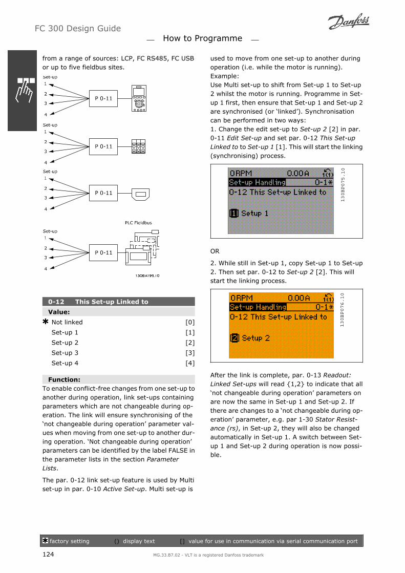
from a range of sources: LCP, FC RS485, FC USBor up to five fieldbus sites.
0-12 This Set-up Linked to
Value:
Not linked [0]
Set-up 1 [1]
Set-up 2 [2]
Set-up 3 [3]
Set-up 4 [4]
Function:To enable conflict-free changes from one set-up toanother during operation, link set-ups containingparameters which are not changeable during op-eration. The link will ensure synchronising of thenot changeable during operation parameter val-ues when moving from one set-up to another dur-ing operation. Not changeable during operationparameters can be identified by the label FALSE inthe parameter lists in the section ParameterLists.
The par. 0-12 link set-up feature is used by Multiset-up in par. 0-10 Active Set-up. Multi set-up is
used to move from one set-up to another duringoperation (i.e. while the motor is running).Example:Use Multi set-up to shift from Set-up 1 to Set-up2 whilst the motor is running. Programme in Set-up 1 first, then ensure that Set-up 1 and Set-up 2are synchronised (or linked). Synchronisationcan be performed in two ways:1. Change the edit set-up to Set-up 2 [2] in par.0-11 Edit Set-up and set par. 0-12 This Set-upLinked to to Set-up 1 [1]. This will start the linking(synchronising) process.
130BP075.10
OR
2. While still in Set-up 1, copy Set-up 1 to Set-up2. Then set par. 0-12 to Set-up 2 [2]. This willstart the linking process.
130BP076.10
After the link is complete, par. 0-13 Readout:Linked Set-ups will read 1,2 to indicate that allnot changeable during operation parameters onare now the same in Set-up 1 and Set-up 2. Ifthere are changes to a not changeable during op-eration parameter, e.g. par 1-30 Stator Resist-ance (rs), in Set-up 2, they will also be changedautomatically in Set-up 1. A switch between Set-up 1 and Set-up 2 during operation is now possi-ble.
FC 300 Design Guide How to Programme
factory setting () display text [] value for use in communication via serial communication port
124 MG.33.B7.02 - VLT is a registered Danfoss trademark

0-13 Readout: Linked Set-ups
Array [5]
Value:
0 - 255 0
Function:View a list of all the set-ups linked by means ofpar. 0-12 This Set-up Linked to. The parameterhas one index for each parameter set-up. Eachset-up shows the set-up bitset to which it islinked.
Example: Set-up 1 and Set-up 2 arelinked
Index LCP value0 01 1,22 1,23 34 4
0-14 Readout: Edit Set-ups / Channel
Value:
0 - FFF.FFF.FFF AAA.AAA.AAA
Function:View the setting of par. 0-11 Edit Set-up for eachof the four different communication channels.When the number is displayed in hex, as it is inthe LCP, each number represents one channel.Numbers 1-4 represent a set-up number; Fmeans factory setting; and A means active set-up. The channels are, from right to left: LCP, FC-bus, USB, HPFB1.5.Example: The number AAAAAA21h means thatthe FC bus selected Set-up 2 in par. 0-11, the LCPselected Set-up 1 and all others used the activeset-up.
0-2* LCP Display
Define the display in the Graphical Logic ControlPanel.
None [0]Profibus Warning Word [953]Readout Transmit Error Counter [1005]Readout Receive Error Counter [1006]Readout Bus Off Counter [1007]Warning Parameter [1013]Running Hours [1501]kWh Counter [1502]Control Word [1600]Reference [Unit] [1601]Reference % [1602]Status Word [1603]Main Actual Value [%] [1605]Custom Readout [1609]Power [kW] [1610]Power [hp] [1611]Motor Voltage [1612]Frequency [1613]Motor Current [1614]Frequency [%] [1615]Torque [1616]* Speed [RPM] [1617]Motor Thermal [1618]KTY Sensor Temperature [1619]Motor Angle [1620]Phase Angle [1621]Torque % [1622]DC Link Voltage [1630]BrakeEnergy/s [1632]BrakeEnergy/2 min [1633]Heatsink Temp. [1634]Inverter Thermal [1635]Inv. Nom. Current [1636]Inv. Max. Current [1637]SL Control State [1638]Control Card Temp. [1639]External Reference [1650]Pulse Reference [1651]Feedback [Unit] [1652]Digi Pot Reference [1653]Digital Input [1660]Terminal 53 Switch Setting [1661]Analog Input 53 [1662]Terminal 54 Switch Setting [1663]Analog Input 54 [1664]Analog Output 42 [mA] [1665]Digital Output [bin] [1666]Freq. Input #29 [Hz] [1667]Freq. Input #33 [Hz] [1668]Pulse Output #27 [Hz] [1669]Pulse Output #29 [Hz] [1670]Relay Output [bin] [1671]Counter A [1672]Counter B [1673]Prec. Stop Counter [1674]Fieldbus CTW 1 [1680]Fieldbus REF 1 [1682]Comm. Option STW [1684]FC Port CTW 1 [1685]FC Port REF 1 [1686]Alarm Word [1690]Alarm Word 2 [1691]Warning Word [1692]
FC 300 Design Guide How to Programme
factory setting () display text [] value for use in communication via serial communication port
MG.33.B7.02 - VLT is a registered Danfoss trademark 125

Warning Word 2 [1693]Ext. Status Word [1694]Ext. Status Word 2 [1695]PCD 1 Write to MCO [3401]PCD 2 Write to MCO [3402]PCD 3 Write to MCO [3403]PCD 4 Write to MCO [3404]PCD 5 Write to MCO [3405]PCD 6 Write to MCO [3406]PCD 7 Write to MCO [3407]PCD 8 Write to MCO [3408]PCD 9 Write to MCO [3409]PCD 10 Write to MCO [3410]PCD 1 Read from MCO [3421]PCD 2 Read from MCO [3422]PCD 3 Read from MCO [3423]PCD 4 Read from MCO [3424]PCD 5 Read from MCO [3425]PCD 6 Read from MCO [3426]PCD 7 Read from MCO [3427]PCD 8 Read from MCO [3428]PCD 9 Read from MCO [3429]PCD 10 Read from MCO [3430]Digital Inputs [3440]Digital Outputs [3441]Actual Position [3450]Commanded Position [3451]Actual Master Position [3452]Slave Index Position [3453]Master Index Position [3454]Curve Position [3455]Track Error [3456]Synchronizing Error [3457]Actual Velocity [3458]Actual Master Velocity [3459]Synchronizing Status [3460]Axis Status [3461]Program Status [3462]Idle Time [9913]Paramdb Requests in Queue [9914]Analog input X30/11 [1675]Analog input X30/12 [1676]Analog output X30/8 mA [1677]
Function:Select a variable for display in line 1, left position.None [0] No display value selectedControl Word [1600] Present control wordReference [Unit] [1601] Total reference (sum ofdigital/analog/preset/bus/freeze ref./catch upand slow-down) in selected unit.Reference % [1602] Total reference (sum of dig-ital/analog/preset/bus/freeze ref./catch up andslow-down) in percent.Status Word [binary] [1603] Present status wordMain actual value [1605] [Hex] One or morewarnings in a Hex code
Power [kW] [1610] Actual power consumed by themotor in kW.Power [hp] [1611] Actual power consumed by themotor in HP.Motor Voltage [V] [1612] Voltage supplied to themotor.Frequency [Hz] [1613] Motor frequency, i.e. theoutput frequency from the frequency converter inHz.Motor Current [A] [1614] Phase current of themotor measured as effective value.Frequency [%] [1615] Motor frequency, i.e. theoutput frequency from the frequency converter inpercent.Torque [%] [1616] Present motor load as a per-centage of the rated motor torque.*Speed [RPM] [1617] Speed in RPM (revolutionsper minute) i.e. the motor shaft speed in closedloop.Motor thermal [1618] Thermal load on the motor,calculated by the ETR function.DC Link Voltage [V] [1630] Intermediate circuitvoltage in the frequency converter.BrakeEnergy/s [1632] Present brake power trans-ferred to an external brake resistor.Stated as an instantaneous value.BrakeEnergy/2 min [1633] Brake power transfer-red to an external brake resistor. The mean poweris calculated continuously for the most recent 120seconds.Heatsink Temperature [oC] [1634] Present heatsink temperature of the frequency converter. Thecut-out limit is 95 ±5 oC; cutting back in occursat 70 ±5° C.Inverter thermal [1635] Percentage load of theinvertersInv. Nom. Current [1636] Nominal current of thefrequency converterInv. Max. Current [1637] Maximum current of thefrequency converterCondition control state [1638] State of the eventexecuted by the controlControl Card Temperature [1639] Temperature ofthe control card.External Reference [1650] [%] Sum of the exter-nal reference as a percentage, i.e. the sum ofanalog/pulse/bus.Pulse Reference [1651] [Hz] Frequency in Hz con-nected to the digital inputs (18, 19 or 32, 33).Feedback [Unit] [1652] Reference value from pro-grammed digital input(s).
FC 300 Design Guide How to Programme
factory setting () display text [] value for use in communication via serial communication port
126 MG.33.B7.02 - VLT is a registered Danfoss trademark

Digital Input [1660] Signal states form the 6 dig-ital terminals (18, 19, 27, 29, 32 and 33). Input18 corresponds to the bit at the far left. Signal low= 0; Signal high = 1 Terminal 53 Switch Setting[1661] Setting of input terminal 54. Current = 0;Voltage = 1.Analog Input 53 [1662] Actual value at input 53either as a reference or protection value.Terminal 54 Switch Setting [1663] Setting of in-put terminal 54. Current = 0; Voltage = 1.Analog Input 54 [1664] Actual value at input 54either as reference or protection value.Analog Output 42 [mA] [1665] Actual value atoutput 42 in mA. Use par. 6-50 to select the valueto be shown.Digital output [bin] [1666] Binary value of all dig-ital outputs.Frequency input #29 [Hz] [1667] Actual value ofthe frequency applied at terminal 29 as an im-pulse input.Frequency input #33 [Hz] [1668] Actual value ofthe frequency applied at terminal 33 as an im-pulse input.Pulse output #27 [Hz] [1669] Actual value of im-pulses applied to terminal 27 in digital outputmode.Pulse output #29 [Hz] [1670] Actual value of im-pulses applied to terminal 29 in digital outputmode.Fieldbus control word1 signal [1680] Control word(CTW) received from the Bus Master.Fieldbus speed set-point A signal [1682] Main ref-erence value sent with control word from the BusMaster.Communication Option Status Word [binary][1684] Extended fieldbus communication optionstatus word.FC port control word1 signal [1685] Control word(CTW) received from the Bus Master.FC port speed set-point A signal [1686] Statusword (STW) sent to the Bus Master.Alarm word [Hex] [1690] One or more alarms ina Hex codeAlarm word 2 [Hex] [1691] One or more alarms ina Hex codeWarning word [Hex] [1692] One or more warn-ings in a Hex codeWarning word 2 [Hex] [1693] One or more warn-ings in a Hex codeExt. status word [Hex] [1694] One or more statusconditions in a Hex code
Ext. status word 2 [Hex] [1695] One or more sta-tus conditions in a Hex code
0-20 Display Line 1.1 Small
Value:
Speed [RPM] [1617]
Function:Select a variable for display in line 1, middle po-sition. The options are the same as listed for par.0-2*.
0-21 Display Line 1.2 Small
Value:
Motor Current [A] [1614]
Function:Select a variable for display in line 1, middle po-sition. The options are the same as listed for par.0-2*.
0-22 Display Line 1.3 Small
Value:
Power [kW] [1610]
Function:Select a variable for display in line 1, right posi-tion. The options are the same as listed for par.0-2*.
0-23 Display Line 2 Large
Value:
Frequency [Hz] [1613]
Function:Select a variable for display in line 2. The optionsare the same as those listed for par. 0-2*.
0-24 Display Line 3 Large
Value:
Reference [%] [1602]
FC 300 Design Guide How to Programme
factory setting () display text [] value for use in communication via serial communication port
MG.33.B7.02 - VLT is a registered Danfoss trademark 127

Function:Select a variable for display in line 3. The optionsare the same as those listed for par. 0-2*.
0-25 My Personal Menu
Array [20]
Value:
0 - 9999
Function:Define up to 20 parameters to include in the Q1Personal Menu, accessible via the [Quick Menu]key on the LCP. The parameters will be displayedin the Q1 Personal Menu in the order they are pro-grammed into this array parameter. Delete pa-rameters by setting the value to 0000.
LCP Custom Readout, Par. 0-3*
It is possible to customize the display elements forvarious purposes: *Custom Readout. Value pro-portional to speed (Linear, squared or cubed de-pending on unit selected in Custom Readout Unit,par. 0-30) *Display Text. Text string stored in aparameter.
Custom ReadoutThe calculated value to be displayed is based onsettings in Custom Readout Unit, par. 0-30, Cus-tom Readout Min Value (linear only), par. 0-31,Custom Readout Max Value, par. 0-32, MotorSpeed High Limit , par. 4-13/4-14, and actualspeed.
The relation will depend on the type of unit selec-ted in par.0-30, Custom Readout Unit:
Unit Type Speed RelationDimensionless LinearSpeedFlow, volumeFlow, massVelocityLengthTemperaturePressure QuadraticPower Cubic
0-30 Custom Readout Unit
Value:
Dimensionless:
None [0]
% [1]
PPM [5]
Speed:
1/min [10]
RPM [11]
Pulse/s [12]
Flow, volume:
l/s [20]
l/min [21]
l/h [22]
m3/s [23]
m3/min [24]
m3/h [25]
Flow, mass:
kg/s [30]
kg/min [31]
kg/h [32]
ton/min [33]
ton/h [34]
Velocity:
m/s [40]
m/min [41]
Length:
m [45]
Temperature:
° C [60]
Pressure:
mbar [70]
bar [71]
Pa [72]
FC 300 Design Guide How to Programme
factory setting () display text [] value for use in communication via serial communication port
128 MG.33.B7.02 - VLT is a registered Danfoss trademark

kPa [73]
m WG [74]
Power:
kW [80]
Flow, volume:
GPM [120]
gal/s [121]
gal/min [122]
gal/h [123]
CFM [124]
ft3/s [125]
ft3/min [126]
ft3/h [127]
Flow, mass:
lb/s [130]
lb/min [131]
lb/h [132]
Velocity:
ft/s [140]
ft/min [141]
Length:
ft [145]
Temperature:
° F [160]
Pressure:
psi [170]
lb/in2 [171]
in WG [172]
ft WG [173]
Power:
HP [180]
Function:It is possible to program a value to be shown inthe display of the LCP. The value will have a linear,squared or cubed relation to speed. This relationwill depend on the unit selected (see table above).The actual calculated value can be read in CustomReadout, par. 16-09, and/or shown in the displaybe selecting Custom Readout [16-09] in par. 0-20 0-24, Display Line X.X Small (large).
0-31 Custom Readout Min Value
Value:
0 - par. 0 - 32 0.00
Function:This parameter allows the choice of the min. valueof the custom defined readout (occurs at zerospeed). Only possible to set different from 0 iswhen selecting a linear unit in Custom ReadoutUnit, par. 0-30. For Quadratic and Cubic units theminimum value will be 0.
0-32 Custom Readout Max Value
Value:
Par. 0-31 - 999999.99 0.00
Function:This parameter allows the choice of the value tobe shown when the speed of the motor hasreached the set value for Motor Speed High Lim-it, (par.4-13/4-14).
0-4* LCP Keypad
Enable and disable individual keys on the LCP key-pad.
0-40 [Hand on] Key on LCP
Value:
Disabled [0]
Enabled [1]
Password [2]
Function:Select Disabled [0] to avoid accidental start of thefrequency converter in Hand mode. Select Pass-word [2] to avoid unauthorised start in Handmode. If par. 0-40 is included in the Quick Menu,then define the password in par. 0-65 Quick MenuPassword.
0-41 [Off] Key on LCP
Value:
Disabled [0]
Enabled [1]
Password [2]
Function:Select Disabled [0] to avoid accidental stop of thefrequency converter. Select Password [2] to avoidunauthorised stop. If par. 0-41 is included in theQuick Menu, then define the password in par. 0-65Quick Menu Password.
FC 300 Design Guide How to Programme
factory setting () display text [] value for use in communication via serial communication port
MG.33.B7.02 - VLT is a registered Danfoss trademark 129

0-42 [Auto on] Key on LCP
Value:
Disabled [0]
Enabled [1]
Password [2]
Function:Select Disabled [0] to avoid accidental start of thefrequency converter in Auto mode. Select Pass-word [2] to avoid unauthorised start in Automode. If par. 0-42 is included in the Quick Menu,then define the password in par. 0-65 Quick MenuPassword.
0-43 [ Reset] Key on LCP
Value:
Disabled [0]
Enabled [1]
Password [2]
Function:Press [Reset] and select Disabled [0] to avoid ac-cidental alarm reset. Press [Reset] and selectPassword [2] to avoid unauthorised resetting. Ifpar. 0-43 is included in the Quick Menu, then de-fine the password in par. 0-65 Quick Menu Pass-word.
0-5* Copy / Save
Copy parameter settings between set-ups and to/from the LCP.
0-50 LCP Copy
Value:
No copy [0]
All to LCP [1]
All from LCP [2]
Size indep. from LCP [3]
File from MCO to LCP [4]
File from LCP to MCO [5]
Function:Select All to LCP [1] to copy all parameters in allset-ups from the frequency converter memory tothe LCP memory.
Select All from LCP all [2] to copy all parametersin all set-ups from the LCP memory to the fre-quency converter memory.Select Size indep. from LCP [3] to copy only theparameters that are independent of the motorsize. The latter selection can be used to pro-gramme several drives with the same functionwithout disturbing motor data. This parametercannot be adjusted while the motor is running.
0-51 Set-up Copy
Value:
No copy [0]
Copy to set-up 1 [1]
Copy to set-up 2 [2]
Copy to set-up 3 [3]
Copy to set-up 4 [4]
Copy to all [9]
Function:Select Copy to set-up 1 [1] to copy all parametersin the present edit set-up (defined in par. 0-11Edit Set-up) to Set-up 1. Likewise, select the op-tion corresponding to the other set-up(s). SelectCopy to all [9] to copy the parameters in thepresent set-up over to each of the set-ups 1 to 4.
0-6* Password
Define password access to menus.
0-60 Main Menu Password
Value:
0 - 999 100
Function:Define the password for access to the Main Menuvia the [Main Menu] key. If par. 0-61 Access toMain Menu w/o Password is set to Full access [0],this parameter will be ignored.
0-61Access to Main Menu w/o Pass-word
Value:
Full access [0]
Read only [1]
No access [2]
FC 300 Design Guide How to Programme
factory setting () display text [] value for use in communication via serial communication port
130 MG.33.B7.02 - VLT is a registered Danfoss trademark

Function:Select Full access [0] to disable the password de-fined in par. 0-60 Main Menu Password. SelectRead only [1] to prevent unauthorised editing ofMain Menu parameters. Select No access [2] toprevent unauthorised viewing and editing of MainMenu parameters. If Full access [0] is selectedthen parameters 0-60, 0-65 and 0-66 will be ig-nored.
0-65 Quick Menu Password
Value:
0 - 999 200
Function:Define the password for access to the Quick Menuvia the [Quick Menu] key. If par. 0-66 Access toQuick Menu w/o Password is set to Full access [0],this parameter will be ignored.
0-66Access to Quick Menu w/o Pass-word
Value:
Full access [0]
Read only [1]
No access [2]
Function:Select Full access [0] to disable the password de-fined in par. 0-65 Quick Menu Password. SelectRead only [1] to prevent unauthorised editing ofQuick Menu parameters. Select No access [2] toprevent unauthorised viewing and editing of QuickMenu parameters. If par. 0-61 Access to MainMenu w/o Password is set to Full access [0] thenthis parameter will be ignored.
FC 300 Design Guide How to Programme
factory setting () display text [] value for use in communication via serial communication port
MG.33.B7.02 - VLT is a registered Danfoss trademark 131

Parameters: Load and Motor
1-0* General Settings
Define whether the frequency converter operatesin speed mode or torque mode; and whether theinternal PID control should be active or not.
1-00 Configuration Mode
Value:
Speed open loop [0]
Speed closed loop [1]
Torque [2]
Process [3]
Function:Select the application control principle to be usedwhen a Remote Reference (via analog input) isactive. A Remote Reference can only be activewhen par. 3-13 Reference Site is set to [0] or [1].Speed open loop [0]: Enables speed control (with-out feedback signal from motor) with automaticslip compensation for almost constant speed atvarying loads.Compensations are active but can be disabled inthe Load/Motor par. group 1-0*.Speed closed loop [1]: Enables encoder feedbackfrom motor. Obtain full holding torque at 0 RPM.For increased speed accuracy, provide a feedbacksignal and set the speed PID control.Torque [2]: Connects the encoder speed feedbacksignal to the encoder input. Only possible withFlux with motor feedback option, par. 1-01 Mo-tor control principle.Process [3]: Enables the use of process control inthe frequency converter. The process control pa-rameters are set in par. groups 7-2* and 7-3*.
1-01 Motor Control Principle
Value:
U/f [0]
VVCplus [1]
Flux sensorless (FC 302 only) [2]
Flux w/ motor feedback (FC302only) [3]
Function:Select which motor control principle to employ.Select U/f [0], a special motor mode, for parallelconnected motors in special motor applications.
When U/f is selected the characteristic of the con-trol principle can be edited in par. 1-55 and 1-56.
Select VVCplus [1] for a Voltage Vector Controlprinciple suitable for most applications. The main
benefit of VVCplus operation is that it uses a robustmotor model.Select Flux sensorless [2], i.e. Flux Vector controlwithout encoder feedback, for simple installationand robustness against sudden load changes.Select Flux with encoder feedback [3] for veryhigh accuracy speed and torque control, suitablefor the most demanding applications.
The best shaft performance is normally achievedusing either of the two Flux Vector control modesFlux sensorless [2] and Flux with encoder feed-back [3].This parameter cannot be adjusted while the mo-tor is running.
1-02 Flux Motor Feedback Source
Value:
24 V encoder [1]
MCB 102 [2]
MCB 103 [3]
MCO 305 encoder 1 [4]
MCO 305 encoder 2 [5]
Function:Select the interface at which to receive feedbackfrom the motor.24V encoder [1] is an A and B channel encoder,which can be connected to the digital input termi-nals 32/33 only. Terminals 32/33 must be pro-grammed to no operation.MCB 102 [2] is an encoder module option whichcan be configured in par. group 17-1*This parameter appears in FC 302 only.MCB 103 [3] is an optional resolver interface mod-ule which can be configured in parameter group17-5*MCO 305 Encoder 1 [4] is encoder interface 1 ofthe optional programmable motion controller MCO305.MCO 305 Encoder 2 [5] is encoder interface 2 ofthe optional programmable motion controller MCO305.
FC 300 Design Guide How to Programme
factory setting () display text [] value for use in communication via serial communication port
132 MG.33.B7.02 - VLT is a registered Danfoss trademark

This parameter cannot be adjusted while the mo-tor is running.
1-03 Torque Characteristics
Value:
Constant torque [0]
Variable torque [1]
Auto energy optim. [2]
Function:Select the torque characteristic required.VT and AEO are both energy saving operations.Constant torque [0]: The motor shaft output willprovide constant torque under variable speedcontrol.Variable Torque [1]: The motor shaft output willprovide variable torque under variable speed con-trol. Set the variable torque level in par. 14-40 VTLevel.Automatic Energy Optimizing function [2]: Thisfunction automatically optimises energy con-sumption by minimising magnetisation and fre-quency via par. 14-41 AEO Minimum Magnetisa-tion and par. 14-42 Minimum AEO Frequency.
This parameter cannot be adjusted while the mo-tor is running.
1-04 Overload Mode
Value:
High torque [0]
Normal torque [1]
Function:High torque [0] allows up to 160% over torque.Normal torque [1] is for oversized motor - allowsup to 110% over torque.This parameter cannot be adjusted while the mo-tor is running.
1-05 Local Mode Configuration
Value:
Speed open loop [0]
Speed closed loop [1]
As conf. mode par. 1-00 [2]
Function:Select which application configuration mode (par.1-00), i.e. application control principle, to usewhen a Local (LCP) Reference is active. A LocalReference can be active only when par. 3-13 Ref-erence Site is set to [0] or [2]. By default the localreference is active in Hand Mode only.
1-1* Motor selection
Parameter group for setting general motor data.This parameter group cannot be adjusted whilethe motor is running.
1-10 Motor Construction
Value:
Asynchronous [0]
PM, non salient SPM (FC 302 only) [1]
Function:Select the motor design type.Select Asynchronous [0] for asynchronous mo-tors.Select PM, non salient SPM (FC 302 only) [1] forpermanent magnet (PM) motors.Note that PM motors are divided into two groups,with either surface mounted (non salient) or inte-rior (salient) magnets.
Motor design can either be asynchronous or per-manent magnet (PM) motor.
1-2* Motor Data
Parameter group 1-2* comprises input data fromthe nameplate on the connected motor.Parameters in parameter group 1-2* cannot beadjusted while the motor is running.
NB!Changing the value of these parame-ters affects the setting of other param-eters.
1-20 Motor Power [kW]
Value:
0.09 - 500 kW [Size related]
Function:Enter the nominal motor power in kW according tothe motor nameplate data. The default value cor-responds to the nominal rated output of the unit.
FC 300 Design Guide How to Programme
factory setting () display text [] value for use in communication via serial communication port
MG.33.B7.02 - VLT is a registered Danfoss trademark 133

This parameter cannot be adjusted while the mo-tor is running.
1-21 Motor Power [HP]
Value:
0.09 - 500 HP [Size related]
Function:Enter the nominal motor power in HP according tothe motor nameplate data. The default value cor-responds to the nominal rated output of the unit.
1-22 Motor Voltage
Value:
10 - 1000 V [Size related]
Function:Enter the nominal motor voltage according to themotor nameplate data. The default value corre-sponds to the nominal rated output of the unit.
1-23 Motor Frequency
Value:
50 Hz(50 HZ) [50]
60 Hz(60 HZ) [60]
Min - Max motor frequency: 20 - 1000Hz
Function:Select the motor frequency value from the motornameplate data. Alternatively, set the value formotor frequency to be infinitely variable. If a val-ue different from 50 Hz or 60 Hz is selected, it isnecessary to adapt the load independent settingsin par. 1-50 to 1-53. For 87 Hz operation with230/400 V motors, set the nameplate data for 230V/50 Hz. Adapt par. 4-13 Motor Speed High Limit[RPM) and par. 3-03 Maximum Reference to the87 Hz application.
1-24 Motor Current
Value:
Motor type dependent.
Function:Enter the nominal motor current value from themotor nameplate data. The data are used for cal-culating torque, motor protection etc.
1-25 Motor Nominal Speed
Value:
100 - 60000 RPM RPM
Function:Enter the nominal motor speed value from themotor nameplate data. The data are used for cal-culating motor compensations.
1-26 Motor Cont. Rated Torque
Value:
1.0 - 10000.0 Nm 5.0Nm
Function:Enter the value from the motor nameplate data.The default value corresponds to the nominal rat-ed output. This parameter is available when par.1-10Motor Design is set to PM, non salient SPM[1], i.e. the parameter is valid for PM and non-sa-lient SPM motors only.
1-29 Automatic Motor Adaptation (AMA)
Value:
OFF [0]
Enable complete AMA [1]
Enable reduced AMA [2]
Function:The AMA function optimises dynamic motor per-formance by automatically optimising the ad-vanced motor parameters (par. 1-30 to par. 1-35)while the motor is stationary.Select the type of AMA. Enable complete AMA [1]performs AMA of the stator resistance RS, the ro-tor resistance Rr, the stator leakage reactancex1, the rotor leakage reactance X2 and the mainreactance Xh. Select this option if an LC filter isused between the drive and the motor.FC 301: The Complete AMA does not include Xh
measurement for FC 301. Instead, the Xh value isdetermined from the motor database. Par. 1-35
Main Reactance (Xh) may be adjusted to obtainoptimal start performance.
FC 300 Design Guide How to Programme
factory setting () display text [] value for use in communication via serial communication port
134 MG.33.B7.02 - VLT is a registered Danfoss trademark

Select Reduced AMA [2] performs a reduced AMAof the stator resistance Rs in the system only. Ac-tivate the AMA function by pressing [Hand on]after selecting [1] or [2]. See also the section Au-tomatic Motor Adaptation. After a normal se-quence, the display will read: "Press [OK] to finishAMA". After pressing the [OK] key the frequencyconverter is ready for operation.Note:
For the best adaptation of the frequencyconverter, run AMA on a cold motor.
AMA cannot be performed while the motoris running.
AMA cannot be performed on permanentmagnet motors.
NB!It is important to set motor par. 1-2*Motor Data correctly, since these formpart of the AMA algorithm. An AMAmust be performed to achieve opti-mum dynamic motor performance. Itmay take up to 10 min, depending onthe power rating of the motor.
NB!Avoid generating external torque dur-ing AMA.
NB!If one of the settings in par. 1-2* Mo-tor Data is changed, par. 1-30 to 1-39,the advanced motor parameters, willreturn to default setting. This param-eter cannot be adjusted while the mo-tor is running.
1-3* Adv. Motor Data
Parameters for advanced motor data. The motordata in par. 1-30 - par. 1-39 must match the rel-evant motor in order to run the motor optimally.The default settings are figures based on commonmotor parameter values from normal standardmotors. If the motor parameters are not set cor-rectly, a malfunction of the drive SYSTEM mayoccur. If the motor data is not known, running anAMA (Automatic Motor Adaptation) is recommen-ded. See the Automatic Motor Adaptation section.The AMA sequence will adjust all motor parame-ters except the moment of inertia of the rotor andthe iron loss resistance (par. 1-36).
Parameters 1-3* and 1-4* cannot be adjustedwhile the motor is running.
Motor equivalent diagram for an asynchronousmotor
1-30 Stator Resistance (Rs)
Value:
Ohm Size related
Function:Set the stator resistance value. Enter the valuefrom a motor data sheet or perform an AMA on acold motor.
1-31 Rotor Resistance (Rr)
Value:
Ohm Size related
Function:Fine-tuning Rr will improve shaft performance. Setthe rotor resistance value using one of thesemethods:
1. Run an AMA on a cold motor. The fre-quency converter will measure the valuefrom the motor. All compensations are re-set to 100%.
2. Enter the Rr value manually. Obtain thevalue from the motor supplier.
3. Use the Rr default setting. The frequencyconverter establishes the setting on thebasis of the motor nameplate data.
1-33 Stator Leakage Reactance (X1)
Value:
Ohm Size related
Function:Set the stator leakage reactance of the motor us-ing one of these methods:
FC 300 Design Guide How to Programme
factory setting () display text [] value for use in communication via serial communication port
MG.33.B7.02 - VLT is a registered Danfoss trademark 135

1. Run an AMA on a cold motor. The fre-quency converter will measure the valuefrom the motor.
2. Enter the X1 value manually. Obtain thevalue from the motor supplier.
3. Use the X1 default setting. The frequencyconverter establishes the setting on thebasis of the motor name plate data.
1-34 Rotor Leakage Reactance (X2)
Value:
Ohm Size related
Function:Set the rotor leakage reactance of the motor usingone of these methods:
1. Run an AMA on a cold motor. The fre-quency converter will measure the valuefrom the motor.
2. Enter the X2 value manually. Obtain thevalue from the motor supplier.
3. Use the X2 default setting. The frequencyconverter establishes the setting on thebasis of the motor name plate data.
1-35 Main Reactance (Xh)
Value:
Ohm Size related
Function:Set the main reactance of the motor using one ofthese methods:
1. Run an AMA on a cold motor. The fre-quency converter will measure the valuefrom the motor.
2. Enter the Xh value manually. Obtain thevalue from the motor supplier.
3. Use the Xh default setting. The frequencyconverter establishes the setting on thebasis of the motor name plate data.
1-36 Iron Loss Resistance (Rfe)
Value:
1 - 10.000 Ω Size related
Function:Enter the equivalent iron loss resistance (RFe) val-ue to compensate for iron losses in the motor.The RFe value cannot be found by performing anAMA.The RFe value is especially important in torquecontrol applications. If RFe is unknown, leave par.1-36 on default setting.
1-37 d-axis Inductance (Ld)
Value:
0.0 - 1000.0 mH 0.0mH
Function:Enter the value of the d-axis inductance. Obtainthe value from the permanent magnet motor datasheet.This parameter is only active when par. 1-10 Mo-tor Design has the value PM, non-salient SPM [1](Permanent Magnet Motor).This parameter is available for FC 302 only.
1-39 Motor Poles
Value:
Depends on motor type
Value 2 - 100 poles 4
Function:Enter the number of motor poles.
Poles ~nn@ 50 Hz ~nn@60 Hz2 2700 - 2880 3250 - 34604 1350 - 1450 1625 - 17306 700 - 960 840 - 1153
The table shows the number of poles for normalspeed ranges of various motor types. Define mo-tors designed for other frequencies separately.The motor pole value is always an even number,because it refers to the total number of poles, notpairs of poles. The frequency converter createsthe initial setting of par. 1-39 based on par.1-23 Motor Frequency and par. 1-25 Motor Nom-inal Speed.
FC 300 Design Guide How to Programme
factory setting () display text [] value for use in communication via serial communication port
136 MG.33.B7.02 - VLT is a registered Danfoss trademark

1-4* LCP Keypad
1-40 Back EMF at 1000 RPM
Value:
10 - 9000 V 500V
Function:Set the nominal back EMF for the motor whenrunning at 1000 RPM. This parameter is only ac-tive when par. 1-10 Motor Design is set toPM mo-tor [1] (Permanent Magnet Motor).This parameter is available for FC 302 only.
1-41 Motor Angle Offset
Value:
0 - 65535 0
Function:Enter the correct offset angle between the PM mo-tor and the index position (single-turn) of the at-tached encoder or resolver. The value range of 0 65535 corresponds to 0 - 2 * pi (radians). Toobtain the offset angle value: After drive start-upapply DC-hold and enter the value of par. 16-20Motor Angle into this parameter.This parameter is only active when par. 1-10 Mo-tor Design is set to PM, non-salient SPM [1] (Per-manent Magnet Motor).
1-5* Load Indep. Setting
Parameters for setting the load-independent mo-tor settings.
1-50 Motor Magnetisation at Zero Speed
Value:
0 - 300 % 100%
Function:Use this par. along with par. 1-51 Min Speed Nor-mal Magnetising [RPM] to obtain a different ther-mal load on the motor when running at lowspeed.Enter a value which is a percentage of the ratedmagnetizing current. If the setting is too low, thetorque on the motor shaft may be reduced.
1-51Min Speed Normal Magnetising[RPM]
Value:
10 - 300 RPM 15RPM
Function:Set the required speed for normal magnetisingcurrent. If the speed is set lower than the motorslip speed, par. 1-50 Motor Magnetisation at ZeroSpeed and par. 1-51 are of no significance.Use this par. along with par. 1-50. See drawing forpar. 1-50.
1-52Min Speed Normal Magnetising[Hz]
Value:
0 - 250 Hz 125 Hz
Function:Set the required frequency for normal magnetis-ing current. If the frequency is set lower than themotor slip frequency, par. 1-50 Motor Magnetisa-tion at Zero Speed are inactive.Use this par. along with par. 1-50. See drawing forpar. 1-50.
1-53 Model Shift Frequency
Value:
4.0 - 50.0 Hz 6.7Hz
Function:Flux Model shiftEnter the frequency value for shift between twomodels for determining motor speed. Choose thevalue based on settings in par. 1-00 ConfigurationMode and par. 1-01 Motor Control Principle. Thereare two options: shift between Flux model 1 andFlux model 2; or shift between Variable Currentmode and Flux model 2. This parameter is avail-able for FC 302 only.
FC 300 Design Guide How to Programme
factory setting () display text [] value for use in communication via serial communication port
MG.33.B7.02 - VLT is a registered Danfoss trademark 137

This parameter cannot be adjusted while the mo-tor is running.
Flux Model 1 Flux model 2This model is used when par. 1-00 is set to Speedclosed loop [1] or Torque [2] and par. 1-01 is setto Flux w/motor feedback [3]. With this parameterit is possible to make an adjustment of the shiftingpoint where FC 302 changes between Flux model1 and Flux model 2, which is useful in some sen-sitive speed and torque control applications.
Par. 1-00 = [1] Speed closed loop or [2] Torqueand par. 1-01 = [3] Flux w/motor feedback
Variable Current - Flux model - SensorlessThis model is used when par. 1-00 is set to Speedopen loop [0] and par. 1-01 is set to Flux sensor-less [2].In speed open loop in flux mode, the speed is de-termined from the current measurement.Below fnorm x 0.1, the drive runs on a VariableCurrent model. Above fnorm x 0.125 the frequencyconverter runs on a Flux model.
Par. 1-00 = [0] Speed open loopPar. 1-01 = [2] Flux sensorless
1-55 U/f Characteristic - U
Value:
0.0 - max. motor voltage Size related
Function:Enter the voltage at each frequency point to man-ually form a U/f-characteristic matching the mo-tor.The frequency points are defined in par. 1-56 U/fCharacteristic - F.This parameter is an array parameter [0-5] and isonly accessible when par. 1-01 Motor Control Prin-ciple is set to U/f [0].
1-56 U/f Characteristic - F
Value:
0.0 - max. motor frequency Size related
Function:Enter the frequency points to manually form a U/f-characteristic matching the motor.The voltage at each point is defined in par. 1-55U/f Characteristic - U.This parameter is an array parameter [0-5] and isonly accessible when par. 1-01 Motor Control Prin-ciple is set to U/f [0].
1-6* Load Depend. Setting
Parameters for adjusting the load-dependent mo-tor settings.
1-60 Low Speed Load Compensation
Value:
0 - 300% 100%
Function:Enter the % value to compensate voltage in rela-tion to load when the motor is running at lowspeed and obtain the optimum U/f characteristic.The motor size determines the frequency rangewithin which this parameter is active.
Motor size Change over0.25 kW - 7.5 kW < 10 Hz
FC 300 Design Guide How to Programme
factory setting () display text [] value for use in communication via serial communication port
138 MG.33.B7.02 - VLT is a registered Danfoss trademark

Description of choice:
1-61 High Speed Load Compensation
Value:
0 - 300% 100%
Function:Enter the % value to compensate voltage in rela-tion to load when the motor is running at highspeed and obtain the optimum U/f characteristic.The motor size determines the frequency rangewithin which this parameter is active.
Motor size Change-over0.25 kW - 7.5 kW > 10 Hz
1-62 Slip Compensation
Value:
-500 - 500 % 100%
Function:Enter the % value for slip compensation, to com-pensate for tolerances in the value of nM,N. Slipcompensation is calculated automatically, i.e. onthe basis of the rated motor speed nM,N.This function is not active when par. 1-00 Config-uration Mode is set to Speed closed loop [1] orTorque [2] Torque control with speed feedback orwhen par. 1-01 Motor Control Principle is set to U/f [0] special motor mode.
1-63 Slip Compensation Time Constant
Value:
0.05 - 5.00 s 0.10s
Function:Enter the slip compensation reaction speed. Ahigh value results in slow reaction, and a low val-
ue results in quick reaction. If low-frequency res-onance problems arise, use a longer time setting.
1-64 Resonance Dampening
Value:
0 - 500 % 100%
Function:Enter the resonance dampening value. Set par.1-64 and par. 1-65 Resonance Dampening TimeConstant to help eliminate high-frequency reso-nance problems. To reduce resonance oscillation,increase the value of par. 1-64.
1-65Resonance Dampening Time Con-stant
Value:
5 - 50 msec. 5 msec.
Function:Set par. 1-64 Resonance Dampening and par.1-65 to help eliminate high-frequency resonanceproblems. Enter the time constant that providesthe best dampening.
1-66 Min. Current at Low Speed
Value:
0 - 200% 100%
Function:Enter the minimum motor current at low speed,see par. 1-53 Model Shift Frequency. Increasingthis current improves motor torque at low speed.Par. 1-66 is enabled when par. 1-00 ConfigurationMode = Speed open loop [0] only. The drive runswith constant current through motor for speedsbelow 10 Hz.For speeds above 10 Hz, the motor flux model inthe drive controls the motor. Par. 4-16 TorqueLimit Motor Mode and / or par. 4-17 Torque LimitGenerator Mode automatically adjust par. 1-66.The parameter with the highest value adjusts par.1-66. The current setting in par. 1-66 is composedof the torque generating current and the magnet-izing current.Example: Set par. 4-16 Torque Limit for MotorMode to 100% and set par. 4-17 Torque Limit forGenerating Mode to 60%. Par. 1-66 automatically
FC 300 Design Guide How to Programme
factory setting () display text [] value for use in communication via serial communication port
MG.33.B7.02 - VLT is a registered Danfoss trademark 139

adjusts to about 127%, depending on the motorsize.This parameter is available for FC 302 only.
1-67 Load Type
Value:
Passive load [0]
Active load [1]
Function:Select passive load [0] for conveyers, fan andpump applications. Select active load [1] for hoist-ing applications. When active load [1] is selected,set par. 1-66 Min. Current at Low Speed to a levelwhich corresponds with maximum torque.This parameter is available for FC 302 only.
1-68 Minimum Inertia
Value:
0.0001 - Par. 1-69 0.0048
Function:Enter the minimum moment of inertia of the me-chanical SYSTEM. Par. 1-68 and par. 1-69 Maxi-mum Inertia are used for pre-adjustment of theProportional Gain in the speed control, see par.7-02 Speed PID Proportional Gain.This parameter is available for FC 302 only.
This parameter cannot be adjusted while motor isrunning.
1-69 Maximum Inertia
Value:
0 - 0.4800 0.0048
Function:Enter the maximum moment of inertia of the me-chanical SYSTEM. Par. 1-68 Minimum Inertia andpar. 1-69 are used for pre-adjustment of the Pro-portional Gain in the speed control, see par. 7-02Speed PID Proportional Gain.This parameter is available for FC 302 only.
This parameter cannot be adjusted while motor isrunning.
1-7* Start Adjustments
Parameters for setting special motor start fea-tures.
1-71 Start Delay
Value:
0.0 - 10.0 s 0.0s
Function:This parameter refers to the start function selec-ted in par. 1-72 Start Function.Enter the time delay required before commencingacceleration.
1-72 Start Function
Value:
DC hold /delay time [0]
DC Brake/delay time [1]
Coast/delay time [2]
Start speed/ current clockwise operation [3]
Horizontal operation [4]
VVCplus/Flux clockwise [5]
Function:Select the start function during start delay . Thisparameter is linked to par. 1-71 Start Delay.Select DC hold /delay time [0] to energize themotor with a DC holding current (par. 2-00) dur-ing the start delay time.Select DC brake /delay time [1] to energize themotor with a DC braking current (par. 2-01) dur-ing the start delay time.Select Coast /delay time [2] to release the shaftcoasted converter during the start delay time (in-verter off).[3] and [4] are only possible with VVC+.Select Start speed/current clockwise [3] to con-nect the function described in par. 1-74 StartSpeed (RPM) and par. 1-76 Start Current in thestart delay time.Regardless of the value applied by the referencesignal, the output speed applies the setting of thestart speed in par. 1-74 or par. 1-75 and the out-put current corresponds to the setting of the startcurrent in par. 1-76 Start Current. This function istypically used in hoisting applications withoutcounterweight and especially in applications witha Cone-motor, where the start is clockwise, fol-lowed by rotation in the reference direction. SelectHorizontal operation [4] to obtain the function de-scribed in par. 1-74 and par. 1-76 during the startdelay time. The motor rotates in the reference di-rection. If the reference signal equals zero (0),
FC 300 Design Guide How to Programme
factory setting () display text [] value for use in communication via serial communication port
140 MG.33.B7.02 - VLT is a registered Danfoss trademark

par. 1-74 Start speed (RPM) is ignored and the output speed equals zero (0). The output currentcorresponds to the setting of the start current inpar. 1-76 Start current.Select VVC+/Flux clockwise [5] for the functiondescribed in par. 1-74 only (Start speed in thestart delay time). The start current is calculatedautomatically. This function uses the start speedin the start delay time only. Regardless of the val-ue set by the reference signal, the output speedequals the setting of the start speed in par.1-74.Start speed/current clockwise [3] andVVCplus/Flux clockwise [5] are typically used inhoisting applications. Start speed/current in ref-erence direction [4] is particularly used in appli-cations with counterweight and horizontal move-ment.
1-73 Flying Start [RPM]
Value:
Off(DISABLE) [0]
On(ENABLE) [1]
Function:This function makes it possible to catch a motorwhich is spinning freely due to a mains drop-out.
Description of choice:Select Disable [0] if this function is not required.Select Enable [1] to enable the frequency con-verter to catch and control a spinning motor.When par. 1-73 is enabled par. 1-71 Start Delayand 1-72 Start Function have no function.
This parameter cannot be adjusted while motor isrunning.
NB!This function is not recommended forhoisting applications.
1-74 Start Speed [RPM]
Value:
0 - 600 RPM 0RPM
Function:Set the motor start speed. After the start signalthe motor output speed leaps to the set value.This parameter can be used for hoist applications
(cone rotor motors). Set the start function in par.1-72 Start Function to [3], [4] or [5], and set astart delay time in par. 1-71 Start Delay. A refer-ence signal must be present.
1-75 Start Speed [Hz]
Value:
0 - 500 Hz 0Hz
Function:Set the motor start speed. After the start signalthe motor output speed leaps to the set value.This parameter can be used for hoist applications(cone rotor motors). Set the start function in par.1-72 Start Function to [3], [4] or [5], and set astart delay time in par. 1-71 Start Delay. A refer-ence signal must be present.
1-76 Start Current
Value:
0.00 - par. 1-24 0.00A
Function:Some motors, such as cone rotor motors, needextra current/starting speed (boost) to disengagethe mechanical brake. Adjust par. 1-74 StartSpeed [RPM] and par. 1-76 to get this boost. Setthe required current value to disengage the me-chanical brake. Set par. 1-72 Start Function to [3]or [4], and set a start delay time in par. 1-71 StartDelay. A reference signal must be present.
1-8* Stop Adjustments
Parameters for setting special stop features forthe motor.
1-80 Function at Stop
Value:
Coast [0]
DC hold [1]
Motor check [2]
Pre-magnetizing [3]
DC Voltage U0 [4]
Function:Select the drive function after a stop command orafter the speed is ramped down to the settings inpar. 1-81 Min Speed for Function at Stop [RPM].
FC 300 Design Guide How to Programme
factory setting () display text [] value for use in communication via serial communication port
MG.33.B7.02 - VLT is a registered Danfoss trademark 141
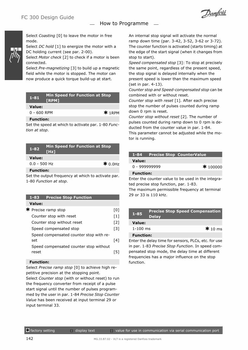
Select Coasting [0] to leave the motor in freemode.Select DC hold [1] to energize the motor with aDC holding current (see par. 2-00).Select Motor check [2] to check if a motor is beenconnected.Select Pre-magnetizing [3] to build up a magneticfield while the motor is stopped. The motor cannow produce a quick torque build-up at start.
1-81Min Speed for Function at Stop[RPM]
Value:
0 - 600 RPM 1RPM
Function:Set the speed at which to activate par. 1-80 Func-tion at stop.
1-82Min Speed for Function at Stop[Hz]
Value:
0.0 - 500 Hz 0.0Hz
Function:Set the output frequency at which to activate par.1-80 Function at stop.
1-83 Precise Stop Function
Value:
Precise ramp stop [0]
Counter stop with reset [1]
Counter stop without reset [2]
Speed compensated stop [3]
Speed compensated counter stop with re-set [4]
Speed compensated counter stop withoutreset [5]
Function:Select Precise ramp stop [0] to achieve high re-petitive precision at the stopping point.Select Counter stop (with or without reset) to runthe frequency converter from receipt of a pulsestart signal until the number of pulses program-med by the user in par. 1-84 Precise Stop CounterValue has been received at input terminal 29 orinput terminal 33.
An internal stop signal will activate the normalramp down time (par. 3-42, 3-52, 3-62 or 3-72).The counter function is activated (starts timing) atthe edge of the start signal (when it changes fromstop to start).Speed compensated stop [3]: To stop at preciselythe same point, regardless of the present speed,the stop signal is delayed internally when thepresent speed is lower than the maximum speed(set in par. 4-13).Counter stop and Speed-compensated stop can becombined with or without reset.Counter stop with reset [1]. After each precisestop the number of pulses counted during rampdown 0 rpm is reset.Counter stop without reset [2]. The number ofpulses counted during ramp down to 0 rpm is de-ducted from the counter value in par. 1-84.This parameter cannot be adjusted while the mo-tor is running.
1-84 Precise Stop CounterValue
Value:
0 - 999999999 100000
Function:Enter the counter value to be used in the integra-ted precise stop function, par. 1-83.The maximum permissible frequency at terminal29 or 33 is 110 kHz.
1-85Precise Stop Speed CompensationDelay
Value:
1-100 ms 10 ms
Function:Enter the delay time for sensors, PLCs, etc. for usein par. 1-83 Precise Stop Function. In speed com-pensated stop mode, the delay time at differentfrequencies has a major influence on the stopfunction.
FC 300 Design Guide How to Programme
factory setting () display text [] value for use in communication via serial communication port
142 MG.33.B7.02 - VLT is a registered Danfoss trademark

1-9* Motor Temperature
Parameters for setting the temperature protectionfeatures for the motor.
1-90 Motor Thermal Protection
Value:
No protection [0]
Thermistor warning [1]
Thermistor trip [2]
ETR warning 1 [3]
ETR trip 1 [4]
ETR warning 2 [5]
ETR trip 2 [6]
ETR warning 3 [7]
ETR trip 3 [8]
ETR warning 4 [9]
ETR trip 4 [10]
Function:The frequency converter determines the motortemperature for motor protection in two differentways:
Via a thermistor sensor connected to oneof the analog or digital inputs (par. 1-93Thermistor Source).
Via calculation (ETR = Electronic TerminalRelay) of the thermal load, based on theactual load and time. The calculated ther-mal load is compared with the rated motorcurrent IM,N and the rated motor frequen-cy fM,N. The calculations estimate the needfor a lower load at lower speed due to less cooling from the fan incorporated in themotor.
Select No protection [0] for a continuously over-loaded motor, when no warning or trip of drive isrequired.Select Thermistor warning [1] to activate a warn-ing when the connected thermistor in the motorreacts in the event of motor over-temperature.Select Thermistor trip [2] to stop (trip) the fre-quency converter when the connected thermistorin the motor reacts in the event of motor over-temperature.
The thermistor cut-out value is > 3 kΩ.
Integrate a thermistor (PTC sensor) in the motorfor winding protection.
Motor protection can be implemented using arange of techniques: PTC sensor in motor wind-ings; mechanical thermal switch (Klixon type); orElectronic Thermal Relay (ETR).See parameter group 1-9* Motor Temperature.
Using a digital input and 24 V as power supply:Example: The frequency converter trips when themotor temperature is too high Parameter set-up:Set Par. 1-90 Motor Thermal Protection to Ther-mistor Trip [2]Set Par. 1-93 Thermistor Source to Digital Input[6]
Using a digital input and 10 V as power supply:Example: The frequency converter trips when themotor temperature is too high.Parameter set-up:Set Par. 1-90 Motor Thermal Protection to Ther-mistor Trip [2]Set Par. 1-93 Thermistor Source to Digital Input[6]
FC 300 Design Guide How to Programme
factory setting () display text [] value for use in communication via serial communication port
MG.33.B7.02 - VLT is a registered Danfoss trademark 143

Using an analog input and 10 V as power supply:Example: The frequency converter trips when themotor temperature is too high.Parameter set-up:Set Par. 1-90 Motor Thermal Protection to Ther-mistor Trip [2]Set Par. 1-93 Thermistor Source to Analog Input54 [2]Do not select a reference source.
InputDigital/ana-log
Supply Volt-ageVolt
ThresholdCut-out Values
Digital 24 V < 6.6 kΩ - > 10.8 kΩDigital 10 V < 800Ω - > 2.7 kΩAnalog 10 V < 3.0 kΩ - > 3.0 kΩ
NB!Check that the chosen supply voltagefollows the specification of the usedthermistor element.
Select ETR Warning 1-4, to activate a warning onthe display when the motor is overloaded.Select ETR Trip 1-4 to trip the frequency converterwhen the motor is overloaded.Programme a warning signal via one of the digitaloutputs. The signal appears in the event of awarning and if the frequency converter trips (ther-mal warning).ETR ( Electronic Terminal Relay ) functions 1-4 willcalculate the load when the set-up where theywere selected is active. For example ETR startscalculating when setup 3 is selected. For the North
American market: The ETR functions provide class20 motor overload protection in accordance withNEC.
1-91 Motor External Fan
Value:
No [0]
Yes [1]
Function:Select No [0] if no external fan is required, i.e. themotor is derated at low speed.Select Yes [1] to apply an external motor fan (ex-ternal ventilation), so no derating of the motor isrequired at low speed. The graph below is followedif the motor current is lower than nominal motorcurrent (see par. 1-24). If the motor current ex-ceeds nominal current, the operation time still de-creases as if no fan were installed.
This parameter cannot be adjusted while the mo-tor is running.
1-93 Thermistor Source
Value:
None [0]
Analog input 53 [1]
Analog input 54 [2]
Digital input 18 [3]
Digital input 19 [4]
Digital input 32 [5]
FC 300 Design Guide How to Programme
factory setting () display text [] value for use in communication via serial communication port
144 MG.33.B7.02 - VLT is a registered Danfoss trademark

Digital input 33 [6]
Function:Select the input to which the thermistor (PTC sen-sor) should be connected. An analog input option[1] or [2] cannot be selected if the analog input isalready in use as a reference source (selected inpar. 3-15 Reference Source 1, 3-16 ReferenceSource 2 or 3-17 Reference Source 3).This parameter cannot be adjusted while the mo-tor is running.
KTY Sensor Connection
FC 302 only)
KTY sensors are used especially in PermanentMagnet Servo Motors (PM motors) for dynamicadjusting of motor parameters as stator resist-ance (par. 1-30) for PM motors and also rotorresistance (par. 1-31) for asynchronous motors,depending on winding temperature. The calcula-tion is:
Rs = Rs20° C x (1 + αcu x ∆T) Ω where
αcu = 0.00393
KTY sensors can be used for motor protecting (par1-97).FC 302 can handle three types of KTY sensors,defined in par 1-95. The actual sensor tempera-ture can be red out from par 16-19.
NB!If the temperature of the motor is uti-lized through a thermistor or KTY sen-sor the PELV is not complied with incase of short circuits between motorwindings and sensor. In order to com-ply with PELV the sensor must be extraisolated.
1-95 KTY Sensor Type
Value:
KTY Sensor 1 [0]
KTY Sensor 2 [1]
KTY Sensor 3 [2]
Function:Select the used type of KTY sensor:
KTY Sensor type 1: 1Kohm at 100 degrees CKTY Sensor type 2: 1Kohm at 25 degrees CKTY Sensor type 3: 2Kohm at 25 degrees C
This parameter only applies for FC 302.
1-96 KTY Thermistor Source
Value:
None [0]
Analog input 54 [2]
Function:Selecting analog input terminal 54 to be used asKTY sensor input. Terminal 54 cannot be selectedas KTY source if otherwise used as reference.
This parameter only applies for FC 302.
1-97 KTY Threshold level
Value:
-40 - 140° C 80° C
Function:Select the KTY sensor threshold level for motorthermal protection. This parameter only appliesfor FC 302.
FC 300 Design Guide How to Programme
factory setting () display text [] value for use in communication via serial communication port
MG.33.B7.02 - VLT is a registered Danfoss trademark 145

Parameters: Brakes
2-** Brakes
Parameter group for setting brake features in thefrequency converter.
2-0* DC-Brakes
Parameter group for configuring the DC brake andDC hold functions.
2-00 DC Hold Current
Value:
0 - 160% 50 %
Function:Enter a value for holding current as a percentageof the rated motor current IM,N set in par. 1-24Motor Current. 100% DC holding current corre-sponds to IM,N.This parameter holds the motor function (holdingtorque) or pre-heats the motor.This parameter is active if DC hold is selected inpar. 1-72 Start Function [0] or par. 1-80 Functionat Stop [1].
NB!The maximum value depends on therated motor current.NB!Avoid 100 % current for too long. Itmay damage the motor.
2-01 DC Brake Current
Value:
0 - 1000 % 50%
Function:Enter a value for current as a percentage of therated motor current IM,N, see par. 1-24 Motor Cur-rent. 100% DC braking current corresponds toIM,N.DC brake current is applied on a stop command,when the speed is lower than the limit set in par.2-03 DC Brake Cut In Speed; when the DC BrakeInverse function is active; or via the serial com-munication port. The braking current is active dur-ing the time period set in par. 2-02 DC BrakingTime.
NB!The maximum value depends on therated motor current.NB!Avoid 100 % current for too long. Itmay damage the motor.
2-02 DC Braking Time
Value:
0.0 - 60.0 s. 10.0s.
Function:Set the duration of the DC braking current set inpar. 2-01, once activated.
2-03 DC Brake Cut In Speed
Value:
0 - par. 4 -13 0RPM
Function:Set the DC brake cut-in speed for activation of theDC braking current set in par. 2-01, upon a stopcommand.
2-1* Brake Energy Funct.
Parameter group for selecting dynamic brakingparameters.
2-10 Brake Function
Value:
Off [0]
Resistor brake [1]
AC brake [2]
Function:Select Off [0] if no brake resistor is installed.Select Resistor brake [1] if a brake resistor is in-corporated in the system, for dissipation of sur-plus brake energy as heat. Connecting a brakeresistor allows a higher DC link voltage duringbraking (generating operation). The Resistorbrake function is only active in frequency convert-ers with an integral dynamic brake.
FC 300 Design Guide How to Programme
factory setting () display text [] value for use in communication via serial communication port
146 MG.33.B7.02 - VLT is a registered Danfoss trademark

2-11 Brake Resistor (ohm)
Value:
Ohm Dependsonunitsize.
Function:Set the brake resistor value in Ohms. This valueis used for monitoring the power to the brake re-sistor in par. 2-13 Brake Power Monitoring. Thisparameter is only active in frequency converterswith an integral dynamic brake.
2-12 Brake Power Limit(kW)
Value:
0.001 - Size related kW
Function:Set the monitoring limit of the brake power trans-mitted to the resistor.The monitoring limit is a product of the maximumduty cycle (120 sec.) and the maximum power ofthe brake resistor at that duty cycle. See the for-mula below.
For 200 - 240 Vunits: Presistor = 3902 × dutytime
R × 120For 380 - 480 Vunits Presistor = 7782 × dutytime
R × 120For 380 - 500 Vunits Presistor = 8102 × dutytime
R × 120For 575 - 600 Vunits Presistor = 9432 × dutytime
R × 120
This parameter is only active in frequency con-verters with an integral dynamic brake.
2-13 Brake Power Monitoring
Value:
Off [0]
Warning [1]
Trip [2]
Warning and Trip [3]
Function:This parameter is only active in frequency con-verters with an integral dynamic brake.This parameter enables monitoring of the powerto the brake resistor. The power is calculated onthe basis of the resistance (par. 2-11 Brake Re-sistor (Ohm)), the DC link voltage, and the resis-tor duty time.
Select Off [0] if no brake power monitoring is re-quired.Select Warning [1] to activate a warning on thedisplay when the power transmitted over 120 sexceeds 100% of the monitoring limit (par.2-12 Brake Power Limit (kW)).The warning disappears when the transmittedpower falls below 80% of the monitoring limit.Select Trip [2] to trip the frequency converter anddisplay an alarm when the calculated power ex-ceeds 100% of the monitoring limit.Select Warning and Trip [3] to activate both of theabove, including warning, trip and alarm.If power monitoring is set to Off [0] or Warning[1], the brake function remains active, even if themonitoring limit is exceeded. This may lead tothermal overload of the resistor. It is also possibleto generate a warning via a relay/digital outputs.The measuring accuracy of the power monitoringdepends on the accuracy of the resistance of theresistor (better than ± 20%).
2-15 Brake Check
Value:
Off [0]
Warning [1]
Trip [2]
Stop and Trip [3]
AC brake [4]
Function:Select type of test and monitoring function tocheck the connection to the brake resistor, orwhether a brake resistor is present, and then dis-play a warning or an alarm in the event of a fault.The brake resistor disconnection function is testedduring power-up, and during braking. Howeverthe brake IGBT test is performed when there is nobraking. A warning or trip disconnects the brakefunction.The testing sequence is as follows:
1. The DC link ripple amplitude is measuredfor 300 ms without braking.
2. The DC link ripple amplitude is measuredfor 300 ms with the brake turned on.
3. If the DC link ripple amplitude while brak-ing is lower than the DC link ripple ampli-
FC 300 Design Guide How to Programme
factory setting () display text [] value for use in communication via serial communication port
MG.33.B7.02 - VLT is a registered Danfoss trademark 147

tude before braking + 1 %. Brake checkfailed, return a warning or alarm.
4. If the DC link ripple amplitude while brak-ing is higher than the DC link ripple am-plitude before braking + 1 %. Brake checkOK.
Select Off [0] to monitor the brake resistor andthe brake IGBT for a short-circuit during opera-tion. If a short-circuit occurs, a warning appears.Select Warning [1] to monitor the brake resistorand brake IGBT for a short-circuit, and to run atest for brake resistor disconnection during pow-er-up.Select Trip [2], to monitor for a short-circuit ordisconnection of the brake resistor, or a short-cir-cuit of the brake IGBT. If a fault occurs the fre-quency converter cuts out while displaying analarm (trip locked).Select Stop and Trip [3] to monitor for a short-circuit or disconnection of the brake resistor, or ashort-circuit of the brake IGBT. If a fault occursthe frequency converter ramps down to coast andthen trips. A trip lock alarm is displayed.Select AC Brake [4] to monitor for a short-circuitor disconnection of the brake resistor, or a short-circuit of the brake IGBT. If a fault occurs thefrequency converter performs a controlled rampdown. This option is available for FC 302 only.
NB!NB!: Remove a warning arising in con-nection with Off [0] or Warning [1] bycycling the mains supply. The faultmust be corrected first. For Off [0]or Warning [1], the frequency convert-er keeps running even if a fault is lo-cated.
This parameter is only active in frequency con-verters with an integral dynamic brake.
2-16 AC Brake Max. Current
Value:
0 - 1000% 100%
Function:Enter the maximum permissible current when us-ing AC brake to avoid overheating of motor wind-ings. The AC brake function is available in Fluxmode only (FC 302 only).
2-17 Over-voltage Control
Value:
Disabled [0]
Enabled (not at stop) [1]
Enabled [2]
Function:Over-voltage control (OVC) reduces the risk of thedrive tripping due to an over voltage on the DClink caused by generative power from the load.Select Disabled [0] if no OVC is required.Select Enabled [2] to activate OVC.Select Enabled (not at stop) [1] to activate OVCexcept when using a stop signal to stop the fre-quency converter.
2-2* Mechanical Brake
Parameters for controlling operation of an electro-magnetic (mechanical) brake, typically required inhoisting applications.To control a mechanical brake, a relay output (re-lay 01 or relay 02) or a programmed digital output(terminal 27 or 29) is required. Normally this out-put must be closed during periods when the driveis unable to hold the motor, e.g. due to an ex-cessive load. Select Mechanical Brake Control [32]for applications with an electro-magnetic brake inpar. 5-40 Function Relay, par. 5-30 Terminal 27Digital Output, or par. 5-31 Terminal 29 DigitalOutput. When selecting Mechanical brake control[32], the mechanical brake is closed from start upuntil the output current is above the level selectedin par. 2-20 Release Brake Current. During stop,the mechanical brake activates when the speedfalls below the level specified in par. 2-21 ActivateBrake Speed [RPM]. If the frequency converterenters an alarm condition or an over-current orover-voltage situation, the mechanical brake im-mediately cuts in. This is also the case during safestop.
FC 300 Design Guide How to Programme
factory setting () display text [] value for use in communication via serial communication port
148 MG.33.B7.02 - VLT is a registered Danfoss trademark

2-20 Release Brake Current
Value:
0.00 - par. 16-37 0.00A
Function:Set the motor current for release of the mechan-ical brake, when a start condition is present. Theupper limit is specified in par. 16-37 Inv. Max.Current.
2-21 Activate Brake Speed [RPM]
Value:
0 - 60.000 0RPM
Function:Set the motor speed for activation of the mechan-ical brake, when a stop condition is present. Theupper speed limit is specified in par. 4-53 WarningSpeed High.
2-22 Activate Brake Speed [Hz]
Value:
0 - 5000 0Hz
Function:Set the motor frequency for activation of the me-chanical brake, when a stop condition is present.
2-23 Activate Brake Delay
Value:
0.0 - 5.0 s 0.0s
Function:Enter the brake delay time of the coast afterramp-down time. The shaft is held at zero speedwith full holding torque. Ensure that the mechan-ical brake has locked the load before the motorenters coast mode. See Control of MechanicalBrake section.
FC 300 Design Guide How to Programme
factory setting () display text [] value for use in communication via serial communication port
MG.33.B7.02 - VLT is a registered Danfoss trademark 149

Parameters: Reference/Ramps
3-** Reference/Reference Limits/Ramps
Parameters for reference handling, definition oflimitations, and configuration of the reaction ofthe frequency converter to changes.
3-0* Reference Limits
Parameters for setting the reference unit, limitsand ranges.
3-00 Reference Range
Value:
Min. - Max [0]
-Max - +Max [1]
Function:Select the range of the reference signal and thefeedback signal. Signal values can be positive on-ly, or positive and negative. The minimum limitmay have a negative value, unless Speed closedloop [1] control or Process [3] is selected in par.1-00 Configuration Mode.Select Min. - Max [0] for positive values only.Select -Max - +Max [1] for both positive and neg-ative values.
3-01 Reference/Feedback Unit
Value:
None [0]
% [1]
RPM [2]
Hz [3]
Nm [4]
PPM [5]
1/min [10]
Pulse/s [12]
I/s [20]
I/min [21]
I/h [22]
m3/s [23]
m3/min [24]
m3/h [25]
kg/s [30]
kg/min [31]
kg/h [32]
t/min [33]
t/h [34]
m/s [40]
m/min [41]
m [45]
º C [60]
Mbar [70]
Bar [71]
Pa [72]
kPa [73]
m WG [74]
kW [80]
GPM [120]
gal/s [121]
gal/min [122]
gal/h [123]
CFM [124]
ft3/s [125]
ft3/min [126]
ft3/h [127]
Ib/s [130]
Ib/min [131]
Ib/h [132]
ft/s [140]
ft/min [141]
ft [145]
Ib ft [150]
º F [160]
psi [170]
Ib/in2 [171]
in WG [172]
ft WG [173]
HP [180]
Function:Select the unit to be used in Process PID Controlreferences and feedbacks.
3-02 Minimum Reference
Value:
-100000.000 par. 3-03 0.000
Function:Enter the Minimum Reference. The Minimum Ref-erence is the lowest value obtainable by summingall references.
FC 300 Design Guide How to Programme
factory setting () display text [] value for use in communication via serial communication port
150 MG.33.B7.02 - VLT is a registered Danfoss trademark

Minimum Reference is active only when par. 3-00Reference Range is set to Min.- Max. [0].The Minimum Reference unit matches- the choice of configuration in par 1-00 Configu-ration Mode: for Speed closed loop [1], RPM; forTorque [2], Nm.- the unit selected in par. 3-01 Reference/Feed-back Unit.
3-03 Maximum Reference
Value:
Par. 3-02 - 100000.000 1500.000
Function:Enter the Maximum Reference. The MaximumReference is the highest value obtainable by sum-ming all references. The Maximum Reference unitmatches- the choice of configuration in par. 1-00 Config-uration Mode: for Speed closed loop [1], RPM; forTorque [2], Nm.- the unit selected in par. 3-01 Reference/Feed-back Unit.
3-04 Reference Function
Value:
Sum [0]
External/Preset [1]
Function:Select Sum [0] to sum both external and presetreference sources.Select External/Preset [1] to use either the presetor the external reference source.
Shift between external and preset via a commandon a digital input.
3-1* References
Parameters for setting up the reference sources.Select the preset reference(s). Select Preset ref.bit 0 / 1 / 2 [16], [17] or [18] for the correspond-ing digital inputs in parameter group 5.1* DigitalInputs.
3-10 Preset Reference
Array [8]Range: 0-7
Value:
-100.00 - 100.00 % 0.00%
Function:Enter up to eight different preset references (0-7)in this parameter, using array programming. Thepreset reference is stated as a percentage of thevalue RefMAX (par. 3-03 Maximum Reference) If aRefMIN different from 0 (Par. 3-02 Minimum Ref-erence) is programmed, the preset reference iscalculated as a percentage of the full referencerange, i.e. on the basis of the difference betweenRefMAX and RefMIN. Afterwards, the value is addedto RefMIN. When using preset references, selectPreset ref. bit 0 / 1 / 2 [16], [17] or [18] for thecorresponding digital inputs in parameter group5.1* Digital Inputs.
3-11 Jog Speed [Hz]
Value:
0.0 - par. 4-14 5Hz
Function:The jog speed is a fixed output speed at which thefrequency converter is running when the jog func-tion is activated.See also par. 3-80.
3-12 Catch up/slow Down Value
Value:
0.00 - 100.00% 0.00%
Function:Enter a percentage (relative) value to be eitheradded to or deducted from the actual reference forCatch up or Slow down respectively. If Catch up isselected via one of the digital inputs (par. 5-10 topar. 5-15), the percentage (relative) value is add-ed to the total reference. If Slow down is selectedvia one of the digital inputs (par. 5-10 to par.5-15), the percentage (relative) value is deducted
FC 300 Design Guide How to Programme
factory setting () display text [] value for use in communication via serial communication port
MG.33.B7.02 - VLT is a registered Danfoss trademark 151

from the total reference. Obtain extended func-tionality with the DigiPot function. See parametergroup 3-9* Digital Potentiometer.
3-13 Reference Site
Value:
Linked to Hand / Auto [0]
Remote [1]
Local [2]
Function:Select which reference site to activate.Select Linked to Hand / Auto [0] to use the localreference when in Hand mode; or the remote ref-erence when in Auto mode.Select Remote [1] to use the remote reference inboth Hand mode and Auto mode.Select Local [2] to use the local reference in bothHand mode and Auto mode.
3-14 Preset Relative Reference
Value:
-100.00 - 100.00 % 0.00%
Function:The actual reference, X, is increased or decreasedwith the percentage Y, set in par.3-14. This re-sults in the actual reference Z. Actual reference(X) is the sum of the inputs selected in par.3-15,Reference Source 1, par.3-16, Reference Source2, par.3-17, Reference Source 3, and par.8-02,Control Word Source.
3-15 Reference Source 1
Value:
No function [0]
Analog input 53 [1]
Analog input 54 [2]
Frequency input 29 (FC 302 only) [7]
Frequency input 33 [8]
Local bus reference [11]
Digital pot.meter [20]
Analog input X30-11 [21]
Analog input X30-12 [22]
Function:Select the reference input to be used for the firstreference signal. Par. 3-15, 3-16 and 3-17 defineup to three different reference signals. The sum ofthese reference signals defines the actual refer-ence.
3-16 Reference Source 2
Value:
No function [0]
Analog input 53 [1]
Analog input 54 [2]
Frequency input 29 (FC 302 only) [7]
Frequency input 33 [8]
Local bus reference [11]
Digital pot.meter [20]
Analog input X30-11 [21]
Analog input X30-12 [22]
Function:Select the reference input to be used for the sec-ond reference signal. Par. 3-15, 3-16 and 3-17define up to three different reference signals. Thesum of these reference signals defines the actualreference.
3-17 Reference Source 3
Value:
No function [0]
Analog input 53 [1]
Analog input 54 [2]
Frequency input 29 (FC 302 only) [7]
Frequency input 33 [8]
FC 300 Design Guide How to Programme
factory setting () display text [] value for use in communication via serial communication port
152 MG.33.B7.02 - VLT is a registered Danfoss trademark

Local bus reference [11]
Digital pot.meter [20]
Analog input X30-11 [21]
Analog input X30-12 [22]
Function:Select the reference input to be used for the thirdreference signal. Par. 3-15, 3-16 and 3-17 defineup to three different reference signals. The sum ofthese reference signals defines the actual refer-ence.
3-18 Relative Scaling Reference Source
Value:
No function [0]
Analog input 53 [1]
Analog input 54 [2]
Frequency input 29 (FC 302 only) [7]
Frequency input 33 [8]
Local bus reference [11]
Digital pot.meter [20]
Analog input X30-11 [21]
Analog input X30-12 [22]
Function:Select a variable value to be added to the fixedvalue (defined in par. 3-14Preset Relative Refer-ence). The sum of the fixed and variable values(labelled Y in the illustration below) is multipliedwith the actual reference (labelled X in the illus-tration below). This product is then added to theactual reference (X+X*Y/100) to give the resul-tant actual reference.
This parameter cannot be adjusted while the mo-tor is running.
3-19 Jog Speed
Value:
0 - par. 4-13 RPM 150RPM
Function:Enter a value for the jog speed nJOG, which is afixed output speed. The frequency converter runsat this speed when the jog function is activated.The maximum limit is defined in par. 4-13 MotorSpeed High Limit (RPM).See also par. 3-80.
Ramps3-4* Ramp 1
For each of four ramps (par. 3-4*, 3-5*, 3-6* and3-7*) configure the ramp parameters: ramp type,ramping times (duration of acceleration and de-celeration) and level of jerk compensation for Sramps.
Start by setting the linear ramping times corre-sponding to the figures and formulae.
If S-ramps are selected then set the level of non-linear jerk compensation required. Set jerk com-pensation by defining the proportion of ramp-upand ramp-down times where acceleration and de-celeration are variable (i.e. increasing or decreas-ing). The S-ramp acceleration and decelerationsettings are defined as a percentage of the actualramp time.
FC 300 Design Guide How to Programme
factory setting () display text [] value for use in communication via serial communication port
MG.33.B7.02 - VLT is a registered Danfoss trademark 153

3-40 Ramp 1 Type
Value:
Linear [0]
S-ramp [1]
Function:Select the ramp type, depending on requirementsfor acceleration/deceleration.A linear ramp will give constant acceleration dur-ing ramping. An S-ramp will give non-linear ac-celeration, compensating for jerk in the applica-tion.
3-41 Ramp 1 Ramp up Time
Value:
0.01 - 3600.00 s s
Function:Enter the ramp-up time, i.e. the acceleration timefrom 0 RPM to the rated motor speed nM,N (par.1-25). Choose a ramp-up time such that the out-put current does not exceed the current limit inpar. 4-18 during ramping. The value 0.00 corre-sponds to 0.01 sec. in speed mode. See ramp-down time in par. 3-42.
Par. 3− 41 =tacc x ηnorm par. 1− 25
∆ ref RPM s
3-42 Ramp 1 Ramp Down Time
Value:
0.01 - 3600.00 s s
Function:Enter the ramp-down time, i.e. the decelerationtime from the rated motor speed nM,N (par. 1-25)to 0 RPM. Choose a ramp-down time such that noover-voltage arises in the inverter due to regen-erative operation of the motor, and such that thegenerated current does not exceed the currentlimit set in par. 4-18. The value 0.00 corresponds
to 0.01 s in speed mode. See ramp-up time in par.3-41.
Par. 3− 42 =tacc x ηnorm par. 1− 25
∆ ref RPM s
3-45Ramp 1 S-ramp Ratio at Accel.Start
Value:
1 - 99% 50%
Function:Enter the proportion of the total ramp-up time(par. 3-41) in which the acceleration torque in-creases. The larger the percentage value, thegreater the jerk compensation achieved, and thusthe lower the torque jerks occurring in the appli-cation.
3-46 Ramp 1 S-ramp Ratio at Accel. End
Value:
1 - 99% 50%
Function:Enter the proportion of the total ramp-up time(par. 3-41) in which the acceleration torque de-creases. The larger the percentage value, thegreater the jerk compensation achieved, and thusthe lower the torque jerks in the application.
3-47Ramp 1 S-ramp Ratio at Decel.Start
Value:
1 - 99% 50%
Function:Enter the proportion of the total ramp-down time(par. 3-42) where the deceleration torque increa-ses. The larger the percentage value, the greaterthe jerk compensation achieved, and thus thelower the torque jerks in the application.
3-48 Ramp 1 S-ramp Ratio at Decel. End
Value:
1 - 99% 50%
Function:Enter the proportion of the total ramp-down time(par. 3-42) where the deceleration torque decrea-ses. The larger the percentage value, the greater
FC 300 Design Guide How to Programme
factory setting () display text [] value for use in communication via serial communication port
154 MG.33.B7.02 - VLT is a registered Danfoss trademark

the jerk compensation achieved, and thus thelower the torque jerks in the application.
3-5* Ramp 2
Choosing ramp parameters, see 3-4*.
3-50 Ramp 2 Type
Value:
Linear [0]
S-ramp [1]
Function:Select the ramp type, depending on requirementsfor acceleration/deceleration. A linear ramp willgive constant acceleration during ramping. An S-ramp will give non-linear acceleration, compen-sating for jerk in the application.
NB!If S-ramp [1] is selected and the ref-erence during ramping is changed theramp time may be prolonged in orderto realize a jerk free movement whichmay result in a longer start or stopway.Additional adjustment of the S-rampratios or switching initiators may benecessary.
3-51 Ramp 2 Ramp up Time
Value:
0.01 - 3600.00 s s
Function:Enter the ramp-up time, i.e. the acceleration timefrom 0 RPM to the rated motor speed nM,N (par.1-25). Choose a ramp-up time such that the out-put current does not exceed the current limit inpar. 4-18 during ramping. The value 0.00 corre-sponds to 0.01 sec. in speed mode. See ramp-down time in par. 3-52.
Par. 3− 51 =tacc x ηnorm par. 1− 25
∆ ref RPM sec
3-52 Ramp 2 Ramp down Time
Value:
0.01 - 3600.00 s. s
Function:Enter the ramp-down time, i.e. the decelerationtime from the rated motor speed nM,N (par. 1-25)to 0 RPM. Choose a ramp-down time such that noover-voltage arises in the inverter due to regen-erative operation of the motor, and such that thegenerated current does not exceed the currentlimit set in par. 4-18. The value 0.00 correspondsto 0.01 s in speed mode. See ramp-up time in par.3-51.
Par. 3− 52 =tdec x ηnorm par. 1− 25
∆ ref RPM sec
3-55Ramp 2 S-ramp Ratio at Accel.Start
Value:
1 - 99% 50%
Function:Enter the proportion of the total ramp-up time(par. 3-51) in which the acceleration torque in-creases. The larger the percentage value, thegreater the jerk compensation achieved, and thusthe lower the torque jerks in the application.
3-56 Ramp 2 S-ramp Ratio at Accel. End
Value:
1 - 99% 50%
Function:Enter the proportion of the total ramp-up time(par. 3-51) in which the acceleration torque de-creases. The larger the percentage value, thegreater the jerk compensation achieved, and thusthe lower the torque jerks in the application.
3-57Ramp 2 S-ramp Ratio at Decel.Start
Value:
1 - 99% 50%
Function:Enter the proportion of the total ramp-down time(par. 3-52) where the deceleration torque increa-ses The larger the percentage value, the greaterthe jerk compensation achieved, and thus thelower the torque jerks in the application.
FC 300 Design Guide How to Programme
factory setting () display text [] value for use in communication via serial communication port
MG.33.B7.02 - VLT is a registered Danfoss trademark 155

3-58 Ramp 2 S-ramp Ratio at Decel. End
Value:
1 - 99% 50%
Function:Enter the proportion of the total ramp-down time(par. 3-52) where the deceleration torque decrea-ses. The larger the percentage value, the greaterthe jerk compensation achieved, and thus thelower the torque jerks in the application.
3-6* Ramp 3
Configure ramp parameters, see 3-4*.
3-60 Ramp 3 Type
Value:
Linear [0]
S-ramp [1]
Function:Select the ramp type, depending on requirementsfor acceleration and deceleration. A linear rampwill give constant acceleration during ramping. AnS-ramp will give non-linear acceleration, compen-sating for jerk in the application.
NB!If S-ramp [1] is selected and the ref-erence during ramping is changed theramp time may be prolonged in orderto realize a jerk free movement whichmay result in a longer start or stopway.Additional adjustment of the S-rampratios or switching initiators may benecessary.
3-61 Ramp 3 Ramp up Time
Value:
0.01 - 3600.00 s s
Function:Enter the ramp-up time, i.e. the acceleration timefrom 0 RPM to the rated motor speed nM,N (par.1-25). Choose a ramp-up time such that the out-put current does not exceed the current limit inpar. 4-18 during ramping. The value 0.00 corre-sponds to 0.01 sec. in speed mode. See ramp-down time in par. 3-62.
3-62 Ramp 3 Ramp down Time
Value:
0.01 - 3600.00 s s
Function:Enter the ramp-down time, i.e. the decelerationtime from the rated motor speed nM,N (par. 1-25)to 0 RPM. Choose a ramp-down time such that noover-voltage arises in the inverter due to regen-erative operation of the motor, and such that thegenerated current does not exceed the currentlimit set in par. 4-18. The value 0.00 correspondsto 0.01 s in speed mode. See ramp-up time in par.3-61.
Par. 3− 62 =tdec x ηnorm par. 1− 25
∆ ref RPM sec
3-65Ramp 3 S-ramp Ratio at Accel.Start
Value:
1 - 99% 50%
Function:Enter the proportion of the total ramp-up time(par. 3-61) in which the acceleration torque in-creases. The larger the percentage value, thegreater the jerk compensation achieved, and thusthe lower the torque jerks in the application.
3-66 Ramp 3 S-ramp Ratio at Accel. End
Value:
1 - 99% 50%
Function:Enter the proportion of the total ramp-up time(par. 3-61) in which the acceleration torque de-creases. The larger the percentage value, thegreater the jerk compensation achieved, and thusthe lower the torque jerks in the application.
3-67Ramp 3 S-ramp Ratio at Decel.Start
Value:
1 - 99% 50%
Function:Enter the proportion of the total ramp-down time(par. 3-62) where the deceleration torque increa-ses. The larger the percentage value, the greater
FC 300 Design Guide How to Programme
factory setting () display text [] value for use in communication via serial communication port
156 MG.33.B7.02 - VLT is a registered Danfoss trademark

the jerk compensation achieved, and thus thelower the torque jerks in the application.
3-68 Ramp 3 S-ramp Ratio at Decel. End
Value:
1 - 99% 50%
Function:Enter the proportion of the total ramp-down time(par. 3-62) where the deceleration torque decrea-ses. The larger the percentage value, the greaterthe jerk compensation achieved, and thus thelower the torque jerks in the application.
3-7* Ramp 4
Configure ramp parameters, see 3-4*.
3-70 Ramp 4 Type
Value:
Linear [0]
S-ramp [1]
Function:Select the ramp type, depending on requirementsfor acceleration and deceleration. A linear rampwill give constant acceleration during ramping. AnS-ramp will give non-linear acceleration, compen-sating for jerk in the application.
NB!If S-ramp [1] is selected and the ref-erence during ramping is changed theramp time may be prolonged in orderto realize a jerk free movement whichmay result in a longer start or stopway.Additional adjustment of the S-rampratios or switching initiators may benecessary.
3-71 Ramp 4 Ramp up Time
Value:
0.01 - 3600.00 s s
Function:Enter the ramp-up time, i.e. the acceleration timefrom 0 RPM to the rated motor speed nM,N (par.1-25). Choose a ramp-up time such that the out-put current does not exceed the current limit inpar. 4-18 during ramping. The value 0.00 corre-
sponds to 0.01 sec. in speed mode. See ramp-down time in par. 3-72.
Par. 3− 71 =tacc x ηnorm par. 1− 25
∆ ref RPM sec
3-72 Ramp 4 Ramp Down Time
Value:
0.01 - 3600.00 s s
Function:Enter the ramp-down time, i.e. the decelerationtime from the rated motor speed nM,N (par. 1-25)to 0 RPM. Choose a ramp-down time such that noover-voltage arises in the inverter due to regen-erative operation of the motor, and such that thegenerated current does not exceed the currentlimit set in par. 4-18. The value 0.00 correspondsto 0.01 s in speed mode. See ramp-up time in par.3-71.
Par. 3− 72 =tdec x ηnorm par. 1− 25
∆ ref RPM sec
3-75Ramp 4 S-ramp Ratio at Accel.Start
Value:
1 - 99% 50%
Function:Enter the proportion of the total ramp-up time(par. 3-71) in which the acceleration torque in-creases. The larger the percentage value, thegreater the jerk compensation achieved, and thusthe lower the torque jerks in the application.
3-76 Ramp 4 S-ramp Ratio at Accel. End
Value:
1 - 99% 50%
Function:Enter the proportion of the total ramp-up time(par. 3-71) in which the acceleration torque de-creases. The larger the percentage value, thegreater the jerk compensation achieved, and thusthe lower the torque jerks in the application.
FC 300 Design Guide How to Programme
factory setting () display text [] value for use in communication via serial communication port
MG.33.B7.02 - VLT is a registered Danfoss trademark 157

3-77Ramp 4 S-ramp Ratio at Decel.Start
Value:
1 - 99% 50%
Function:Enter the proportion of the total ramp-down time(par. 3-72) where the deceleration torque increa-ses. The larger the percentage value, the greaterthe jerk compensation achieved, and thus thelower the torque jerks in the application.
3-78 Ramp 4 S-ramp Ratio at Decel. End
Value:
1 - 99% 50%
Function:Enter the proportion of the total ramp-down time(par. 3-72) where the deceleration torque decrea-ses. The larger the percentage value, the greaterthe jerk compensation achieved, and thus thelower the torque jerks in the application.
3-8* Other Ramps
Configure parameters for special ramps e.g. Jogor Quick Stop.
3-80 Jog Ramp Time
Value:
0.01 - 3600.00 s s
Function:Enter the jog ramp time, i.e. the acceleration/de-celeration time between 0 RPM and the rated mo-tor frequency nM,N (set in par. 1-25 Motor NominalSpeed). Ensure that the resultant output currentrequired for the given jog ramp time does not ex-ceed the current limit in par. 4-18. The jog ramptime starts upon activation of a jog signal via thecontrol panel, a selected digital input, or the serialcommunication port.
Par. 3− 80 =t jog x ηnorm par. 1− 25∆ log speed par. 3− 19 sec
3-81 Quick Stop Ramp Time
Value:
0.01 - 3600.00 s 3s
Function:Enter the quickstop ramp-down time, i.e. the de-celeration time from the rated motor speed to 0RPM. Ensure that no resultant over-voltage willarise in the inverter due to regenerative operationof the motor required to achieve the given ramp-down time. Ensure also that the generated currentrequired to achieve the given ramp-down timedoes not exceed the current limit (set in par.4-18). Quick-stop is activated by means of a sig-nal on a selected digital input, or via the serialcommunication port.
Par. 3− 81 =tQstop x ηnorm par. 1− 25∆ jog ref par. 3− 19 sec
3-9* Digital Pot.Meter
The digital potentiometer function allows the userto increase or decrease the actual reference byadjusting the set-up of the digital inputs using the
FC 300 Design Guide How to Programme
factory setting () display text [] value for use in communication via serial communication port
158 MG.33.B7.02 - VLT is a registered Danfoss trademark

functions INCREASE, DECREASE or CLEAR. To ac-tivate the function, at least one digital input mustbe set up to INCREASE or DECREASE.
3-90 Step Size
Value:
0.01 - 200.00% 0.10%
Function:Enter the increment size required for INCREASE/DECREASE, as a percentage of the nominal speedset in par. 1-25. If INCREASE / DECREASE is ac-tivated the resulting reference will be increased /decreased by the amount set in this parameter.
3-91 Ramp Time
Value:
0.000 - 3600.00 s 1.00s
Function:Enter the ramp time, i.e. the time for adjustmentof the reference from 0% to 100% of the specifieddigital potentiometer function (INCREASE, DE-CREASE or CLEAR).If INCREASE / DECREASE is activated for longerthan the ramp delay period specified in par. 3-95the actual reference will be ramped up / down ac-cording to this ramp time. The ramp time is de-fined as the time used to adjust the reference bythe step size specified in par. 3-90 Step Size.
3-92 Power Restore
Value:
Off [0]
On [1]
Function:Select Off [0] to reset the Digital Potentiometerreference to 0% after power up.Select On [1] to restore the most recent DigitalPotentiometer reference at power up.
3-93 Maximum Limit
Value:
-200 - 200 % 100%
Function:Set the maximum permissible value for the resul-tant reference. This is advisable if the Digital Po-tentiometer is used for fine tuning of the resultingreference.
3-94 Minimum Limit
Value:
-200 - 200 % -100%
Function:Set the minimum permissible value for the resul-tant reference. This is advisable if the Digital Po-tentiometer is used for fine tuning of the resultingreference.
3-95 Ramp Delay
Value:
0.000 - 3600.00 s 1.000s
Function:Enter the delay required from activation of thedigital potentiometer function until the frequencyconverter starts to ramp the reference. With a de-lay of 0 ms, the reference starts to ramp as soonas INCREASE / DECREASE is activated. See alsopar. 3-91 Ramp Time.
FC 300 Design Guide How to Programme
factory setting () display text [] value for use in communication via serial communication port
MG.33.B7.02 - VLT is a registered Danfoss trademark 159

Parameters: Limits/Warn-ings
4-** Limits and Warnings
Parameter group for configuring limits and warn-ings.
4-1* Motor Limits
Define torque, current and speed limits for themotor, and the reaction of the frequency convert-er when the limits are exceeded.A limit may generate a message on the display. Awarning will always generate a message on thedisplay or on the fieldbus. A monitoring functionmay initiate a warning or a trip, upon which thefrequency converter will stop and generate analarm message.
4-10 Motor Speed Direction
Value:
Clockwise [0]
Counter clockwise [1]
Both directions [2]
Function:Select the motor speed direction(s) required. Usethis parameter to prevent unwanted reversing.When par. 1-00 Configuration Mode is set to Proc-ess [3], par. 4-10 is set to Clockwise [0] as de-fault. The setting in par. 4-10 does not limitoptions for setting par.4-13.This parameter cannot be adjusted while the mo-tor is running.
4-11 Motor Speed Low Limit [RPM]
Value:
0 - par. 4-13 0RPM
Function:Enter the minimum limit for motor speed. The Mo-tor Speed Low Limit can be set to correspond tothe manufacturers recommended minimum mo-tor speed. The Motor Speed Low Limit must notexceed the setting in par. 4-13 Motor Speed HighLimit [RPM].
4-12 Motor Speed Low Limit [Hz]
Value:
0 - par. 4-14 0Hz
Function:Enter the minimum limit for motor speed. The Mo-tor Speed Low Limit can be set to correspond tothe minimum output frequency of the motor shaft.The Motor Speed Low Limit must not exceed thesetting in par. 4-14 Motor Speed High Limit [Hz].
4-13 Motor Speed High Limit [RPM]
Value:
Par. 4-11 - 60.000 3600. RPM
Function:Enter the maximum limit for motor speed. TheMotor Speed High Limit can be set to correspondto the manufacturers maximum rated motorspeed. The Motor Speed High Limit must exceedthe setting in par. 4-11 Motor Speed Low Limit[RPM].
NB!The output frequency value of the fre-quency converter must not exceed avalue higher than 1/10 of the switch-ing frequency.
4-14 Motor Speed High Limit [Hz]
Value:
Par. 4-12 - 1000 120 Hz
Function:Enter the maximum limit for motor speed. TheMotor Speed High Limit can be set to correspondto the manufacturers recommended maximumfrequency of the motor shaft. The Motor SpeedHigh Limit must exceed the setting in par. 4-12Motor Speed Low Limit [Hz].
NB!The output frequency value of the fre-quency converter must not exceed avalue higher than 1/10 of the switch-ing frequency.
4-16 Torque Limit Motor Mode
Value:
0.0 - Variable Limit % 160.0 %
Function:Sets the torque limit for motor operation. The tor-que limit is active in the speed range up to the
FC 300 Design Guide How to Programme
factory setting () display text [] value for use in communication via serial communication port
160 MG.33.B7.02 - VLT is a registered Danfoss trademark

rated motor speed (par. 1-25). To protect the mo-tor from reaching the stalling torque, the defaultsetting is 1.6 x the rated motor torque (calculatedvalue). If a setting in par. 1-00 to par. 1-26 ischanged, par. 4-16 to 4-18 are not automaticallyreset to the default settings.
Changing par. 4-16 Torque Limit MotorMode when par. 1-00 is set to Speedopen loop [0], par. 1-66 Min Current atLow Speed is automatically readjus-ted.
4-17 Torque Limit Generator Mode
Value:
0.0 - Variable Limit % 160.0 %
Function:Sets the torque limit for generator mode opera-tion. The torque limit is active in the speed rangeup to the rated motor speed (par. 1-25). See il-lustration for par. 4-16 as well as par. 14-25 forfurther details.
4-18 Current Limit
Value:
0.0 - Variable Limit % 160.0 %
Function:Sets the current limit for motor operation. To pro-tect the motor from reaching the stalling torque,the default setting is 1.6 x the rated motor torque(calculated value). If a setting in par. 1-00 to par.1-26 is changed, par. 4-16 to par. 4-18 are notautomatically reset to the default settings.
4-19 Max Output Frequency
Value:
0.0 - 1000.0 Hz 132.0Hz
Function:Provides a final limit on the drive output frequencyfor improved safety in applications where youwant to avoid accidental over-speeding. This limitis final in all configurations (independent of thesetting in par. 1-00).
NB!Max. output frequency cannot exceed10% of the inverter switching frequen-cy (par. 14-01).
Par. 4-19 cannot be adjusted while the motor isrunning.
4-20 Torque Limit Factor SourceOption
Value:
No function [0]
Analog input 53 [2]
Analog input 53 inv [4]
Analog input 54 [6]
Analog input 54 inv [8]
Analog input X30-11 [10]
Analog input X30-11 inv [12]
Analog input X30-12 [14]
Analog input X30-12 inv [16]
Function:Select an analog input for scaling the settings inpar. 4-16 and 4-17 from 0% to 100% (or inverse).The signal levels corresponding to 0% and 100%are defined in the analog input scaling, e.g. par.group 6-1*. This parameter is only active whenpar. 1-00 Configuration Mode is in Speed OpenLoop or Speed Closed Loop.
4-21 Speed Limit Factor SourceOption
Value:
No function [0]
Analog input 53 [2]
Analog input 53 inv [4]
Analog input 54 [6]
Analog input 54 inv [8]
Analog input X30-11 [10]
Analog input X30-11 inv [12]
Analog input X30-12 [14]
Analog input X30-12 inv [16]
FC 300 Design Guide How to Programme
factory setting () display text [] value for use in communication via serial communication port
MG.33.B7.02 - VLT is a registered Danfoss trademark 161

Function:Select an analog input for scaling the settings inpar. 4-19 from 0% to 100% (or inverse). The sig-nal levels corresponding to 0% and 100% are de-fined in the analog input scaling, e.g. par. group6-1*. This parameter is only active when par.1-00 Configuration Mode is in Torque Mode.
4-3* Motor Feedback Monitoring
The parameter group includes monitoring andhandling of motor feedback devices as encoders,resolvers etc.
4-30 Motor Feedback Loss Function
Value:
Disabled [0]
Warning [1]
Trip [2]
Function:Select which reaction the frequency convertershould take in the case a feedback fault is detec-ted. The selected action will take place if the feed-back signal differs from the output speed withmore than specified in par. 4-31 during the timeset in par. 4-32.
4-31 Motor Feedback Speed Error
Value:
1-600 RPM 300RPM
Function:Select the max allowed tracking error in speedfrom the calculated and the actual mechanicalshaft output speed.
4-32 Motor Feedback Loss Timeout
Value:
0.00 - 60.00 sec 0sec
Function:Set the timeout value allowing the speed error setin par. 4-31 to be exceeded.
4-5* Adjustable Warnings
Define adjustable warning limits for current,speed, reference and feedback. Warnings areshown on the display, programmed output or se-rial bus.
Warnings are shown on display, programmed out-put or serial bus.
4-50 Warning Current Low
Value:
0.00 - par. 4-51 0.00A
Function:Enter the ILOW value. When the motor current fallsbelow this limit (ILOW), the display reads CURRENTLOW. The signal outputs can be programmed toproduce a status signal on terminal 27 or 29 andon relay output 01 or 02. Refer to the drawing inthis section.
4-51 Warning Current High
Value:
Par. 4-50 - par. 16-37 par. 16-37 A
Function:Enter the IHIGH value. When the motor current ex-ceeds this limit (IHIGH), the display reads CUR-RENT HIGH. The signal outputs can be program-
FC 300 Design Guide How to Programme
factory setting () display text [] value for use in communication via serial communication port
162 MG.33.B7.02 - VLT is a registered Danfoss trademark

med to produce a status signal on terminal 27 or29 and on relay output 01 or 02. Refer to thedrawing in this section.
4-52 Warning Speed Low
Value:
0 - par. 4-13 0 RPM
Function:Enter the nLOW value. When the motor speed ex-ceeds this limit (nLOW), the display reads SPEEDLOW. The signal outputs can be programmed toproduce a status signal on terminal 27 or 29 (FC302 only) and on relay output 01 or 02 (FC 302only).
4-53 Warning Speed High
Value:
Par. 4-52 - par. 4-13 par. 4-13 RPM
Function:Enter the nHIGH value. When the motor speed ex-ceeds this limit (nHIGH), the display reads SPEEDHIGH. The signal outputs can be programmed toproduce a status signal on terminal 27 or 29 andon relay output 01 or 02. Programme the uppersignal limit of the motor speed, nHIGH, within thenormal working range of the frequency converter.Refer to the drawing in this section.
4-54 Warning Reference Low
Value:
-999999.999 - par. 4-55 -999999.999
Function:Enter the lower reference limit. When the actualreference falls below this limit, the display indi-cates Ref Low. The signal outputs can be pro-grammed to produce a status signal on terminal27 or 29 and on relay output 01 or 02.
4-55 Warning Reference High
Value:
Par. 4-54 - 999999.999 999999.999
Function:Enter the upper reference limit. When the actualreference exceeds this limit, the display reads RefHigh. The signal outputs can be programmed to
produce a status signal on terminal 27 or 29 andon relay output 01 or 02.
4-56 Warning Feedback Low
Value:
-999999.999 - par. 4-57 -999999.999
Function:Enter the lower feedback limit. When the feedbackfalls below this limit, the display reads Feedb Low.The signal outputs can be programmed to producea status signal on terminal 27 or 29 and on relayoutput 01 or 02.
4-57 Warning Feedback High
Value:
Par. 4-56 - 999999.999 999999.999
Function:Enter the upper feedback limit. When the feed-back exceeds this limit, the display reads FeedbHigh. The signal outputs can be programmed toproduce a status signal on terminal 27 or 29 andon relay output 01 or 02.
4-58 Missing Motor Phase Function
Value:
Off [0]
On [1]
Function:Select On, to display an alarm in the event of amissing motor phase. Select Off, for no alarm inthe event of a missing motor phase. However, ifthe motor runs on only two phases, it can be dam-aged by overheating. Retaining the On setting istherefore strongly recommended.This parameter cannot be adjusted while the mo-tor is running.
4-6* Speed Bypass
Define the Speed Bypass areas for the ramps.Some systems call for avoiding certain output fre-quencies or speeds, due to resonance problems inthe system. A maximum of four frequency orspeed ranges can be avoided.
FC 300 Design Guide How to Programme
factory setting () display text [] value for use in communication via serial communication port
MG.33.B7.02 - VLT is a registered Danfoss trademark 163

4-60 Bypass Speed From [RPM]
Array [4]
Value:
0 - par. 4-13 0 RPM
Function:Some systems call for avoiding certain outputspeeds due to resonance problems in the system.Enter the lower limits of the speeds to be avoided.
4-61 Bypass Speed From [Hz]
Array [4]
Value:
0 - par. 4-14 Hz 0 Hz
Function:Some systems call for avoiding certain outputspeeds due to resonance problems in the system.Enter the lower limits of the speeds to be avoided.
4-62 Bypass Speed To [RPM]
Array [4]
Value:
0 - par. 4-13 0RPM
Function:Some systems call for avoiding certain outputspeeds due to resonance problems in the system.Enter the upper limits of the speeds to be avoided.
4-63 Bypass Speed To [Hz]
Array [4]
Value:
0 - par. 4-14 0 Hz
Function:Some systems call for avoiding certain outputspeeds due to resonance problems in the system.Enter the upper limits of the speeds to be avoided.
FC 300 Design Guide How to Programme
factory setting () display text [] value for use in communication via serial communication port
164 MG.33.B7.02 - VLT is a registered Danfoss trademark
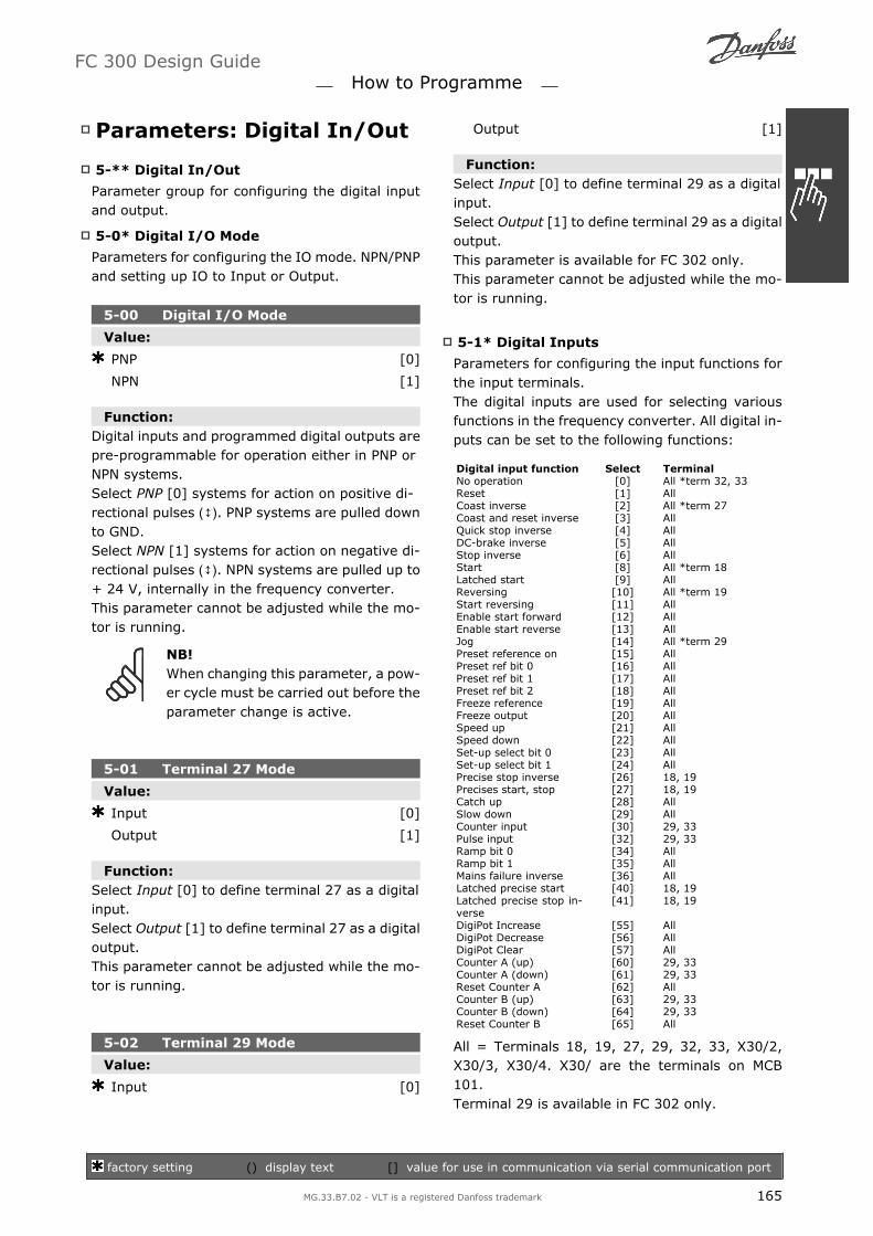
Parameters: Digital In/Out
5-** Digital In/Out
Parameter group for configuring the digital inputand output.
5-0* Digital I/O Mode
Parameters for configuring the IO mode. NPN/PNPand setting up IO to Input or Output.
5-00 Digital I/O Mode
Value:
PNP [0]
NPN [1]
Function:Digital inputs and programmed digital outputs arepre-programmable for operation either in PNP orNPN systems.Select PNP [0] systems for action on positive di-rectional pulses (). PNP systems are pulled downto GND.Select NPN [1] systems for action on negative di-rectional pulses (). NPN systems are pulled up to+ 24 V, internally in the frequency converter.This parameter cannot be adjusted while the mo-tor is running.
NB!When changing this parameter, a pow-er cycle must be carried out before theparameter change is active.
5-01 Terminal 27 Mode
Value:
Input [0]
Output [1]
Function:Select Input [0] to define terminal 27 as a digitalinput.Select Output [1] to define terminal 27 as a digitaloutput.This parameter cannot be adjusted while the mo-tor is running.
5-02 Terminal 29 Mode
Value:
Input [0]
Output [1]
Function:Select Input [0] to define terminal 29 as a digitalinput.Select Output [1] to define terminal 29 as a digitaloutput.This parameter is available for FC 302 only.This parameter cannot be adjusted while the mo-tor is running.
5-1* Digital Inputs
Parameters for configuring the input functions forthe input terminals.The digital inputs are used for selecting variousfunctions in the frequency converter. All digital in-puts can be set to the following functions:
Digital input function Select TerminalNo operation [0] All *term 32, 33Reset [1] AllCoast inverse [2] All *term 27Coast and reset inverse [3] AllQuick stop inverse [4] AllDC-brake inverse [5] AllStop inverse [6] AllStart [8] All *term 18Latched start [9] AllReversing [10] All *term 19Start reversing [11] AllEnable start forward [12] AllEnable start reverse [13] AllJog [14] All *term 29Preset reference on [15] AllPreset ref bit 0 [16] AllPreset ref bit 1 [17] AllPreset ref bit 2 [18] AllFreeze reference [19] AllFreeze output [20] AllSpeed up [21] AllSpeed down [22] AllSet-up select bit 0 [23] AllSet-up select bit 1 [24] AllPrecise stop inverse [26] 18, 19Precises start, stop [27] 18, 19Catch up [28] AllSlow down [29] AllCounter input [30] 29, 33Pulse input [32] 29, 33Ramp bit 0 [34] AllRamp bit 1 [35] AllMains failure inverse [36] AllLatched precise start [40] 18, 19Latched precise stop in-verse
[41] 18, 19
DigiPot Increase [55] AllDigiPot Decrease [56] AllDigiPot Clear [57] AllCounter A (up) [60] 29, 33Counter A (down) [61] 29, 33Reset Counter A [62] AllCounter B (up) [63] 29, 33Counter B (down) [64] 29, 33Reset Counter B [65] All
All = Terminals 18, 19, 27, 29, 32, 33, X30/2,X30/3, X30/4. X30/ are the terminals on MCB101.Terminal 29 is available in FC 302 only.
FC 300 Design Guide How to Programme
factory setting () display text [] value for use in communication via serial communication port
MG.33.B7.02 - VLT is a registered Danfoss trademark 165

Functions dedicated to only one digital input arestated in the associated parameter.
All digital inputs can be programmed to thesefunctions:
No operation [0]: The frequency con-verter will not react to signals transmittedto the terminal.
Reset [1]: Reset the frequency converterafter a TRIP/ALARM. Not all alarms can bereset.
Coast inverse [2] (Default Digital input27): Coasting stop, inverted input (NC).The frequency converter leaves the motorin free mode. Logic 0 => coasting stop.
Coast and reset inverse [3]: Reset andcoasting stop Inverted input (NC). Thefrequency converter leaves the motor infree mode and resets the drive. Logic 0=> coasting stop and reset.
Quick stop inverse [4]: Inverted input(NC). Generate a stop in accordance withthe quick-stop ramp time set in par. 3-81.When the motor stops, the shaft is in freemode. Logic 0 => Quick-stop.
DC-brake inverse [5]: Inverted inputfor DC braking (NC). Stops the motor byenergizing it with a DC current for a cer-tain time period. See par. 2-01 to par.2-03. The function is only active when thevalue in par. 2-02 is different from 0. Log-ic 0 => DC braking.
Stop inverse [6]:Stop Inverted func-tion. Generate a stop function when theselected terminal goes from logical level1 to 0. The stop is performed accordingto the selected ramp time (par. 3-42, par.3-52, par. 3-62, par. 3-72).
NB!When the frequency converter is at thetorque limit and has received a stopcommand, it may not stop by itself. Toensure that the frequency converterstops, configure a digital output toTorque limit & stop [27] and connectthis digital output to a digital input thatis configured as coast.
Start [8] (Default Digital input 18): Se-lect start for a start/stop command. Logic1 = start, logic 0 = stop.
Latched start [9]: The motor starts, if apulse is applied for min. 2 ms. The motorstops when Stop inverse is activated.
Reversing [10]: (Default Digital input19). Change the direction of motor shaftrotation. Select Logic 1 to reverse. Thereversing signal only changes the direc-tion of rotation. It does not activate thestart function. Select both directions inpar. 4-10 Motor Speed Direction. Thefunction is not active in Speed closedloop [1] or Torque [2] control in par. 1-00Configuration Mode.
Start reversing [11]: Use for start/stopand for reversing on the same wire. Sig-nals on start are not allowed at the sametime.
Enable start forward [12]: Use if themotor shaft must rotate clockwise atstart.
Enable start reverse [13]: Use if themotor shaft must rotate counter-clock-wise at start.
Jog [14] (Default Digital input 29): Useto activate jog speed. See par. 3-11.
Preset reference on [15]: Use for shift-ing between external reference and pre-set reference. It is assumed that External/preset [1] has been selected in par. 3-04.Logic '0' = external reference active; logic'1' = one of the eight preset references isactive.
Preset ref bit 0 [16]: Preset ref. bit 0,1,and 2 enables a choice between one of theeight preset references according to thetable below.
Preset ref bit 1 [17]: Same as Preset refbit 0 [16].
Preset ref bit 2 [18]: Preset ref bit 2[18]: Same as Preset ref bit 0 [16].
FC 300 Design Guide How to Programme
factory setting () display text [] value for use in communication via serial communication port
166 MG.33.B7.02 - VLT is a registered Danfoss trademark
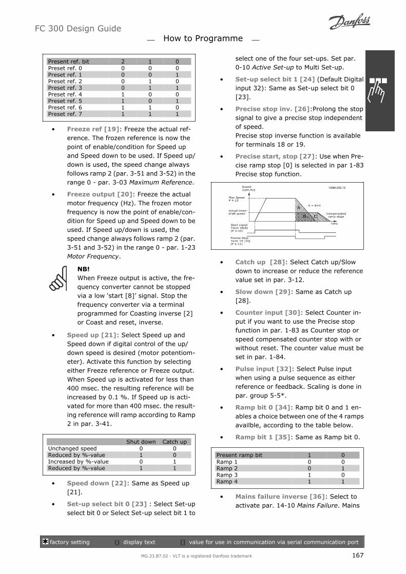
Present ref. bit 2 1 0Preset ref. 0 0 0 0Preset ref. 1 0 0 1Preset ref. 2 0 1 0Preset ref. 3 0 1 1Preset ref. 4 1 0 0Preset ref. 5 1 0 1Preset ref. 6 1 1 0Preset ref. 7 1 1 1
Freeze ref [19]: Freeze the actual ref-erence. The frozen reference is now thepoint of enable/condition for Speed upand Speed down to be used. If Speed up/down is used, the speed change alwaysfollows ramp 2 (par. 3-51 and 3-52) in therange 0 - par. 3-03 Maximum Reference.
Freeze output [20]: Freeze the actualmotor frequency (Hz). The frozen motorfrequency is now the point of enable/con-dition for Speed up and Speed down to beused. If Speed up/down is used, thespeed change always follows ramp 2 (par.3-51 and 3-52) in the range 0 - par. 1-23Motor Frequency.
NB!When Freeze output is active, the fre-quency converter cannot be stoppedvia a low start [8] signal. Stop thefrequency converter via a terminalprogrammed for Coasting inverse [2]or Coast and reset, inverse.
Speed up [21]: Select Speed up andSpeed down if digital control of the up/down speed is desired (motor potentiom-eter). Activate this function by selectingeither Freeze reference or Freeze output.When Speed up is activated for less than400 msec. the resulting reference will beincreased by 0.1 %. If Speed up is acti-vated for more than 400 msec. the result-ing reference will ramp according to Ramp2 in par. 3-41.
Shut down Catch upUnchanged speed 0 0Reduced by %-value 1 0Increased by %-value 0 1Reduced by %-value 1 1
Speed down [22]: Same as Speed up[21].
Set-up select bit 0 [23] : Select Set-upselect bit 0 or Select Set-up select bit 1 to
select one of the four set-ups. Set par.0-10 Active Set-up to Multi Set-up.
Set-up select bit 1 [24] (Default Digitalinput 32): Same as Set-up select bit 0[23].
Precise stop inv. [26]:Prolong the stopsignal to give a precise stop independentof speed.Precise stop inverse function is availablefor terminals 18 or 19.
Precise start, stop [27]: Use when Pre-cise ramp stop [0] is selected in par 1-83Precise stop function.
Catch up [28]: Select Catch up/Slowdown to increase or reduce the referencevalue set in par. 3-12.
Slow down [29]: Same as Catch up[28].
Counter input [30]: Select Counter in-put if you want to use the Precise stopfunction in par. 1-83 as Counter stop orspeed compensated counter stop with orwithout reset. The counter value must beset in par. 1-84.
Pulse input [32]: Select Pulse inputwhen using a pulse sequence as eitherreference or feedback. Scaling is done inpar. group 5-5*.
Ramp bit 0 [34]: Ramp bit 0 and 1 en-ables a choice between one of the 4 rampsavailble, according to the table below.
Ramp bit 1 [35]: Same as Ramp bit 0.
Present ramp bit 1 0Ramp 1 0 0Ramp 2 0 1Ramp 3 1 0Ramp 4 1 1
Mains failure inverse [36]: Select toactivate par. 14-10 Mains Failure. Mains
FC 300 Design Guide How to Programme
factory setting () display text [] value for use in communication via serial communication port
MG.33.B7.02 - VLT is a registered Danfoss trademark 167
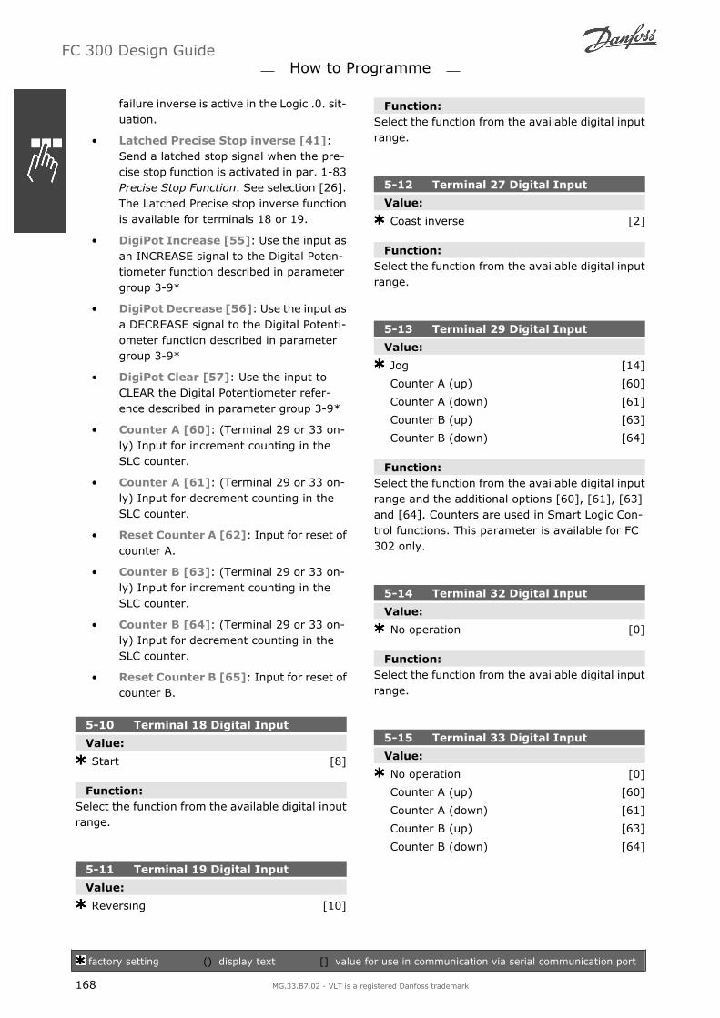
failure inverse is active in the Logic .0. sit-uation.
Latched Precise Stop inverse [41]:Send a latched stop signal when the pre-cise stop function is activated in par. 1-83Precise Stop Function. See selection [26].The Latched Precise stop inverse functionis available for terminals 18 or 19.
DigiPot Increase [55]: Use the input asan INCREASE signal to the Digital Poten-tiometer function described in parametergroup 3-9*
DigiPot Decrease [56]: Use the input asa DECREASE signal to the Digital Potenti-ometer function described in parametergroup 3-9*
DigiPot Clear [57]: Use the input toCLEAR the Digital Potentiometer refer-ence described in parameter group 3-9*
Counter A [60]: (Terminal 29 or 33 on-ly) Input for increment counting in theSLC counter.
Counter A [61]: (Terminal 29 or 33 on-ly) Input for decrement counting in theSLC counter.
Reset Counter A [62]: Input for reset ofcounter A.
Counter B [63]: (Terminal 29 or 33 on-ly) Input for increment counting in theSLC counter.
Counter B [64]: (Terminal 29 or 33 on-ly) Input for decrement counting in theSLC counter.
Reset Counter B [65]: Input for reset ofcounter B.
5-10 Terminal 18 Digital Input
Value:
Start [8]
Function:Select the function from the available digital inputrange.
5-11 Terminal 19 Digital Input
Value:
Reversing [10]
Function:Select the function from the available digital inputrange.
5-12 Terminal 27 Digital Input
Value:
Coast inverse [2]
Function:Select the function from the available digital inputrange.
5-13 Terminal 29 Digital Input
Value:
Jog [14]
Counter A (up) [60]
Counter A (down) [61]
Counter B (up) [63]
Counter B (down) [64]
Function:Select the function from the available digital inputrange and the additional options [60], [61], [63]and [64]. Counters are used in Smart Logic Con-trol functions. This parameter is available for FC302 only.
5-14 Terminal 32 Digital Input
Value:
No operation [0]
Function:Select the function from the available digital inputrange.
5-15 Terminal 33 Digital Input
Value:
No operation [0]
Counter A (up) [60]
Counter A (down) [61]
Counter B (up) [63]
Counter B (down) [64]
FC 300 Design Guide How to Programme
factory setting () display text [] value for use in communication via serial communication port
168 MG.33.B7.02 - VLT is a registered Danfoss trademark
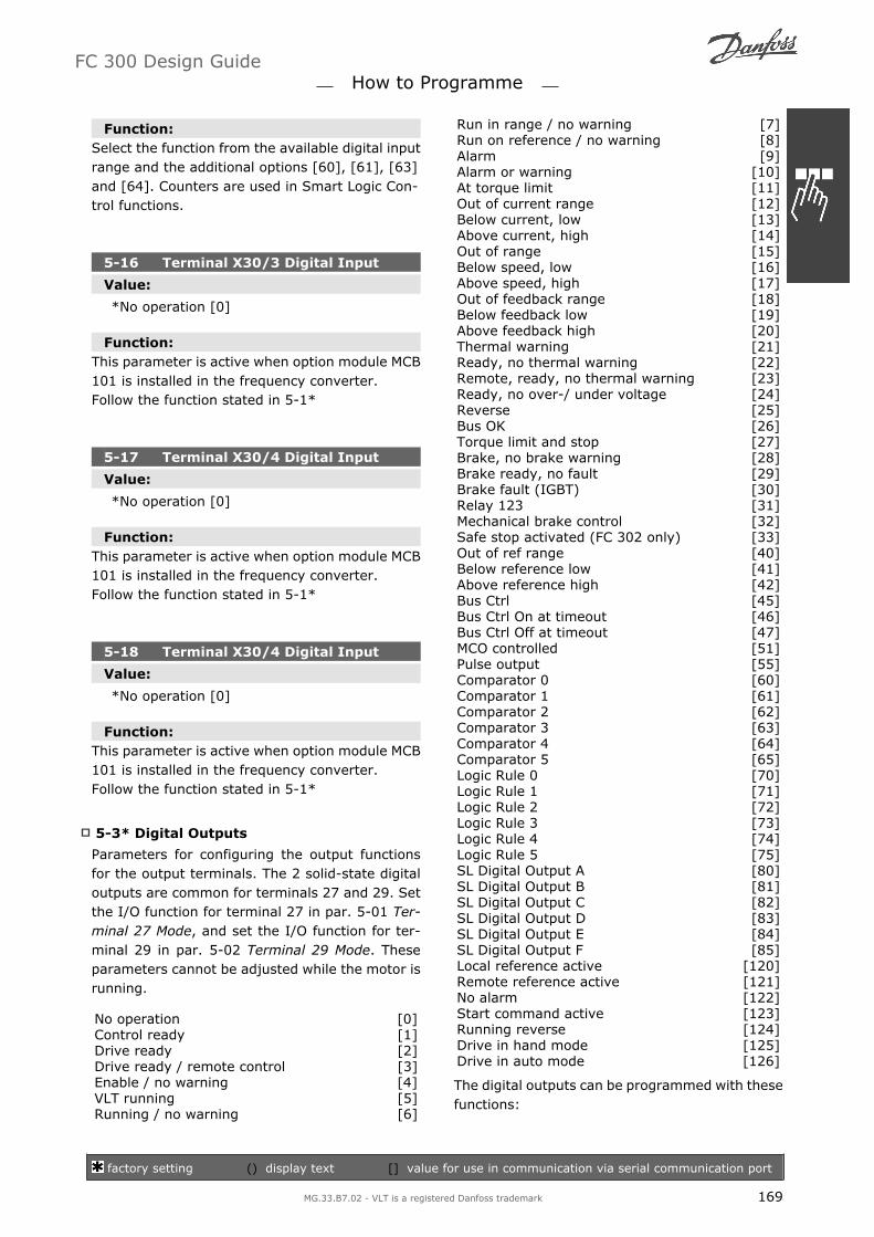
Function:Select the function from the available digital inputrange and the additional options [60], [61], [63]and [64]. Counters are used in Smart Logic Con-trol functions.
5-16 Terminal X30/3 Digital Input
Value:
*No operation [0]
Function:This parameter is active when option module MCB101 is installed in the frequency converter.Follow the function stated in 5-1*
5-17 Terminal X30/4 Digital Input
Value:
*No operation [0]
Function:This parameter is active when option module MCB101 is installed in the frequency converter.Follow the function stated in 5-1*
5-18 Terminal X30/4 Digital Input
Value:
*No operation [0]
Function:This parameter is active when option module MCB101 is installed in the frequency converter.Follow the function stated in 5-1*
5-3* Digital Outputs
Parameters for configuring the output functionsfor the output terminals. The 2 solid-state digitaloutputs are common for terminals 27 and 29. Setthe I/O function for terminal 27 in par. 5-01 Ter-minal 27 Mode, and set the I/O function for ter-minal 29 in par. 5-02 Terminal 29 Mode. Theseparameters cannot be adjusted while the motor isrunning.
No operation [0]Control ready [1]Drive ready [2]Drive ready / remote control [3]Enable / no warning [4]VLT running [5]Running / no warning [6]
Run in range / no warning [7]Run on reference / no warning [8]Alarm [9]Alarm or warning [10]At torque limit [11]Out of current range [12]Below current, low [13]Above current, high [14]Out of range [15]Below speed, low [16]Above speed, high [17]Out of feedback range [18]Below feedback low [19]Above feedback high [20]Thermal warning [21]Ready, no thermal warning [22]Remote, ready, no thermal warning [23]Ready, no over-/ under voltage [24]Reverse [25]Bus OK [26]Torque limit and stop [27]Brake, no brake warning [28]Brake ready, no fault [29]Brake fault (IGBT) [30]Relay 123 [31]Mechanical brake control [32]Safe stop activated (FC 302 only) [33]Out of ref range [40]Below reference low [41]Above reference high [42]Bus Ctrl [45]Bus Ctrl On at timeout [46]Bus Ctrl Off at timeout [47]MCO controlled [51]Pulse output [55]Comparator 0 [60]Comparator 1 [61]Comparator 2 [62]Comparator 3 [63]Comparator 4 [64]Comparator 5 [65]Logic Rule 0 [70]Logic Rule 1 [71]Logic Rule 2 [72]Logic Rule 3 [73]Logic Rule 4 [74]Logic Rule 5 [75]SL Digital Output A [80]SL Digital Output B [81]SL Digital Output C [82]SL Digital Output D [83]SL Digital Output E [84]SL Digital Output F [85]Local reference active [120]Remote reference active [121]No alarm [122]Start command active [123]Running reverse [124]Drive in hand mode [125]Drive in auto mode [126]
The digital outputs can be programmed with thesefunctions:
FC 300 Design Guide How to Programme
factory setting () display text [] value for use in communication via serial communication port
MG.33.B7.02 - VLT is a registered Danfoss trademark 169

No operation [0]: Default for all digitaloutputs and relay outputs
Control ready [1]: The control board re-ceives supply voltage.
Drive ready [2]: The frequency convert-er is ready for operation and applies asupply signal on the control board.
Drive ready / remote control [3]: Thefrequency converter is ready for operationand is in Auto On mode.
Enable / no warning [4]: The frequen-cy converter is ready for operation. Nostart or stop command is been given(start/disable). There are no warnings.
VLT running [5]: The motor is running.
Running / no warning [6]: The outputspeed is higher than the speed set in par.1-81Min Speed for Function at Stop[RPM]. The motor is running and there areno warnings.
Run in range / no warning [7]: Themotor is running within the programmedcurrent and speed ranges set in par. 4-50to par. 4-53. There are no warnings.
Run on reference / no warning [8]:The motor runs at reference speed.
Alarm [9]: An alarm activates the out-put. There are no warnings.
Alarm or warning [10]: An alarm or awarning activates the output.
At torque limit [11]: The torque limitset in par. 4-16 or par. 1-17 has been ex-ceeded.
Out of current range [12]: The motorcurrent is outside the range set in par.4-18.
Below current, low [13]: The motorcurrent is lower than set in par. 4-50.
Above current, high [14]: The motorcurrent is higher than set in par. 4-51.
Out of range [15]: The output frequen-cy is outside the frequency range set inany limit parameter.
Below speed, low[16]: The outputspeed is lower than the setting in par.4-52.
Above speed, high [17]: The outputspeed is higher than the setting in par.4-53.
Out of feedback range [18]: The feed-back is outside the range set in par. 4-56and 4-57.
Below feedback low [19]: The feed-back is below the limit set in par. 4-56Warning Feedback Low.
Above feedback high [20]: The feed-back is above the limit set in par. 4-57Warning Feedback High.
Thermal warning [21]: The thermalwarning turns on when the temperatureexceeds the limit in the motor, the fre-quency converter, the brake resistor, orthe thermistor.
Ready, no thermal warning [22]: Thefrequency converter is ready for operationand there is no over-temperature warn-ing.
Remote, ready, no thermal warning[23]: The frequency converter is readyfor operation and is in Auto On mode.There is no over-temperature warning.
Ready, no over-/ under voltage [24]:The frequency converter is ready for op-eration and the mains voltage is withinthe specified voltage range (see GeneralSpecifications section).
Reverse [25]:Reversing. Logic 1 = re-lay activated, 24 V DC when CW rotationof the motor. Logic 0 = relay not activa-ted, no signal, when CCW rotation of themotor.
Bus OK [26]: Active communication (notime-out) via the serial communicationport.
Torque limit & stop [27]: Use in per-forming a coasting stop and in torque limitcondition. If the frequency converter hasreceived a stop signal and is at the torquelimit, the signal is Logic 0.
Brake, no brake warning [28]: Thebrake is active and there are no warnings.
Brake ready, no fault [29]: The brakeis ready for operation and there are nofaults.
FC 300 Design Guide How to Programme
factory setting () display text [] value for use in communication via serial communication port
170 MG.33.B7.02 - VLT is a registered Danfoss trademark

Brake fault (IGBT) [30]: The output isLogic 1 when the brake IGBT is short-circuited. Use this function to protect thefrequency converter if there is a fault onthe brake modules. Use the output/relayto cut out the main voltage from the fre-quency converter.
Relay 123 [31]: The relay is activatedwhen Control Word [0] is selected in pa-rameter group 8-**.
Mechanical brake control [32]: Ena-bles control of an external mechanicalbrake, see description in the section Con-trol of Mechanical Brake, and par. group2-2*
Safe stop activated [33]: Indicatesthat the safe stop on terminal 37 has beenactivated.
Out of ref range [40]
Below reference low [41]
Above reference high [42]
Bus Ctrl [45]
Bus Ctrl On at time-out [46]
Bus Ctrl Off at time-out [47]
MCO controlled [51]
Pulse output [55]
Comparator 0 [60]: See par. group13-1*. If Comparator 0 is evaluated asTRUE, the output will go high. Otherwise,it will be low.
Comparator 1 [61]: See par. group13-1*. If Comparator 1 is evaluated asTRUE, the output will go high. Otherwise,it will be low.
Comparator 2 [62]: See par. group13-1*. If Comparator 2 is evaluated asTRUE, the output will go high. Otherwise,it will be low.
Comparator 3 [63]: See par. group13-1*. If Comparator 3 is evaluated asTRUE, the output will go high. Otherwise,it will be low.
Comparator 4 [64]: See par. group13-1*. If Comparator 4 is evaluated asTRUE, the output will go high. Otherwise,it will be low.
Comparator 5 [65]: See par. group13-1*. If Comparator 5 is evaluated asTRUE, the output will go high. Otherwise,it will be low.
Logic Rule 0 [70]: See par. group13-4*. If Logic Rule 0 is evaluated asTRUE, the output will go high. Otherwise,it will be low.
Logic Rule 1 [71]: See par. group13-4*. If Logic Rule 1 is evaluated asTRUE, the output will go high. Otherwise,it will be low.
Logic Rule 2 [72]: See par. group13-4*. If Logic Rule 2 is evaluated asTRUE, the output will go high. Otherwise,it will be low.
Logic Rule 3 [73]: See par. group13-4*. If Logic Rule 3 is evaluated asTRUE, the output will go high. Otherwise,it will be low.
Logic Rule 4 [74]: See par. group13-4*. If Logic Rule 4 is evaluated asTRUE, the output will go high. Otherwise,it will be low.
Logic Rule 5 [75]: See par. group13-4*. If Logic Rule 5 is evaluated asTRUE, the output will go high. Otherwise,it will be low.
SL Digital Output A [80]: See par.13-52 SL Control Action. The input will gohigh whenever the Smart Logic Action[38] Set dig. out. A high is executed. Theinput will go low whenever the Smart Log-ic Action [32] Set dig. out. A low is exe-cuted.
SL Digital Output B [81]: See par.13-52 SL Control Action. The input will gohigh whenever the Smart Logic Action[39] Set dig. out. A high is executed. Theinput will go low whenever the Smart Log-ic Action [33] Set dig. out. A low is exe-cuted.
SL Digital Output C [82]: See par.13-52SL Control Action. The input will gohigh whenever the Smart Logic Action[40] Set dig. out. A high is executed. Theinput will go low whenever the Smart Log-ic Action [34] Set dig. out. A low is exe-cuted.
FC 300 Design Guide How to Programme
factory setting () display text [] value for use in communication via serial communication port
MG.33.B7.02 - VLT is a registered Danfoss trademark 171

SL Digital Output D [83]: See par.13-52 SL Control Action. The input will gohigh whenever the Smart Logic Action[41] Set dig. out. A high is executed. Theinput will go low whenever the Smart Log-ic Action [35] Set dig. out. A low is exe-cuted.
SL Digital Output E [84]: See par.13-52 SL Control Action. The input will gohigh whenever the Smart Logic Action[42] Set dig. out. A high is executed. Theinput will go low whenever the Smart Log-ic Action [36] Set dig. out. A low is exe-cuted.
SL Digital Output F [85]: See par.13-52 SL Control Action. The input will gohigh whenever the Smart Logic Action[43] Set dig. out. A high is executed. Theinput will go low whenever the Smart Log-ic Action [37] Set dig. out. A low is exe-cuted.
Local reference active [120]: The out-put is high when par. 3-13 ReferenceSite = [2] Local or when par. 3-13Refer-ence Site = [0] Linked to hand auto at thesame time as the LCP is in Hand on mode.
Remote reference active [121]: Theoutput is high when par. 3-13 ReferenceSite = Remote [1] or Linked to hand/au-to [0] while the LCP is in [Auto on] mode.
No alarm [122]: The output is highwhen no alarm is present.
Start command active [123]: The out-put is high when there is an active Startcommand (i.e. via digital input bus con-nection or [Hand on] or [Auto on], and noStop or Start command is active.
Running reverse [124]: The output ishigh when the drive is running counterclockwise (the logical product of the sta-tus bits running AND reverse).
Drive in hand mode [125]: The outputis high when the drive is in Hand on mode(as indicated by the LED light above[Hand on].
Drive in auto mode [126]: The outputis high when the drive is in Hand on mode(as indicated by the LED light above [Autoon].
5-30 Terminal 27 Digital Output
Value:
Bus ctrl. [45]
Bus ctrl. on at timeout [46]
Bus ctrl. off at timeout [47]
Function:Select Bus ctrl. [45] to control the output via bus.The state of the output is set in par. 5-90. Theoutput state is retained in the event of bus time-out.Select Bus ctrl. On at time-out [46] to control theoutput via bus. The state of the output is set inpar. 5-90. In the event of bus time-out the outputstate is set high (On).Select Bus ctrl. Off at time-out [47] to control theoutput via bus. The state of the output is set inpar. 5-90. In the event of bus time-out the outputstate is set low (Off).
5-31 Terminal 29 Digital Output
Value:
Bus ctrl. [45]
Bus ctrl. on at timeout [46]
Bus ctrl. off at timeout [47]
Function:Select Bus ctrl. [45] to control the output via bus.The state of the output is set in par. 5-90. Theoutput state is retained in the event of bus time-out.Select Bus ctrl. On at time-out [46] to control theoutput via bus. The state of the output is set inpar. 5-90. In the event of bus time-out the outputstate is set high (On).Select Bus ctrl. Off at time-out [47] to control theoutput via bus. The state of the output is set inpar. 5-90. In the event of bus time-out the outputstate is set low (Off).This parameter only applies for FC 302.
FC 300 Design Guide How to Programme
factory setting () display text [] value for use in communication via serial communication port
172 MG.33.B7.02 - VLT is a registered Danfoss trademark

5-32Terminal X30/6 Digital Output(MCB 101)
Value:
No operation [0]
Function:This parameter is active when option module MCB101 is mounted in the frequency converter.Follow the function stated in 5-3*.
5-33Terminal X30/7 Digital Output(MCB 101)
Value:
No operation [0]
Function:This parameter is active when option module MCB101 is mounted in the frequency converter.Follow the function stated in 5-3*.
5-4* Relays
Parameters for configuring the timing and the out-put functions for the relays.
5-40 Function Relay
Value:
(Relay 1) [1]
(Relay 2) [2]
Relay 7 [7]
Relay 8 [8]
Relay 9 [9]
Control word bit 11 [36]
Control word bit 12 [37]
Relay 2 is included in FC 302 only. Par.5-40 functions are as for par.5-3*, in-cluding options 36 and 37.
Function:Par. 5-40 options are as for par. 5-30, includingoptions 36 and 37. Relay 2 is included in FC 302only. Relay 7, 8 and 9 are included in MCB 105Relay option module.
5-41 On Delay, Relay
Array [8] (Relay 1 [0], Relay 2 [1], Relay7 [6], Relay 8 [7], Relay 9 [8])
Value:
0.01 - 600.00 s 0.01s
Function:Enter the delay of the relay cut-in time. Select oneof available mechanical relays and MCO 105 in anarray function. See par. 5-40.
5-42 Off Delay, Relay
Array [8] (Relay 1 [0], Relay 2 [1], Relay7 [6], Relay 8 [7], Relay 9 [8])
Value:
0.01 - 600.00 s. 0.01s
Function:Enter the delay of the relay cut-out time. Selectone of available mechanical relays and MCO 105in an array function. See par. 5-40.
If the Selected Event condition changes before theon- or off delay timer expires, the relay output isunaffected.
FC 300 Design Guide How to Programme
factory setting () display text [] value for use in communication via serial communication port
MG.33.B7.02 - VLT is a registered Danfoss trademark 173

5-5* Pulse Input
The pulse input parameters are used to define anappropriate window for the impulse referencearea by configuring the scaling and filter settingsfor the pulse inputs. Input terminals 29 or 33 actas frequency reference inputs. Set terminal 29(par. 5-13) or terminal 33 (par. 5-15) to Pulse in-put [32]. If terminal 29 is used as an input, thenset par. 5-01 to Input [0].
5-50 Term. 29 Low Frequency
Value:
0 - 110000 Hz 100Hz
Function:Enter the low frequency limit corresponding to thelow motor shaft speed (i.e. low reference value)in par. 5-52. Refer to the diagram in this section.This parameter is available for FC 302 only.
5-51 Term. 29 High Frequency
Value:
0 - 110000 Hz 100Hz
Function:Enter the high frequency limit corresponding tothe high motor shaft speed (i.e. high referencevalue) in par. 5-53.This parameter is available for FC 302 only.
5-52 Term. 29 Low Ref./Feedb. Value
Value:
-1000000.000 - par. 5-53 0.000
Function:Enter the low reference value limit for the motorshaft speed [RPM]. This is also the lowest feed-back value, see also par. 5-57. Set terminal 29 todigital output (par. 5-02 =Output [1] and par.5-13 = applicable value).This parameter is available for FC 302 only.
5-53 Term. 29 High Ref./Feedb. Value
Value:
Par. 5-52 - 1000000.000 1500.000
Function:Enter the high reference value [RPM] for the mo-tor shaft speed and the high feedback value, seealso par.5-58. Select terminal 29 as a digital out-put (par. 5-02 =Output [1] and par. 5-13 = ap-plicable value).This parameter is available for FC 302 only.
5-54 Pulse Filter Time Constant #29
Value:
1 - 1000 ms 100ms
Function:Enter the pulse filter time constant. The pulse fil-ter dampens oscillations of the feedback signal,which is an advantage if there is a lot of noise inthe SYSTEM. A high time constant value results inbetter dampening but also increases the time de-lay through the filter. This parameter is availablefor FC 302 only.This parameter cannot be adjusted while the mo-tor is running.
5-55 Term. 33 Low Frequency
Value:
0 - 110000 Hz 100Hz
Function:Enter the low frequency corresponding to the lowmotor shaft speed (i.e. low reference value) inpar. 5-57. Refer to the diagram in this section.
5-56 Term. 33 High Frequency
Value:
0 - 110000 Hz 100Hz
Function:Enter the high frequency corresponding to thehigh motor shaft speed (i.e. high reference value)in par. 5-58.
FC 300 Design Guide How to Programme
factory setting () display text [] value for use in communication via serial communication port
174 MG.33.B7.02 - VLT is a registered Danfoss trademark

5-57 Term. 33 Low Ref./Feedb. Value
Value:
-100000.000 par. 5-58) 0.000
Function:Enter the low reference value [RPM] for the motorshaft speed. This is also the low feedback value,see also par. 5-52.
5-58 Term. 33 High Ref./Feedb. Value
Value:
Par. 5-57 - 100000.000 1500.000
Function:Enter the high reference value [RPM] for the mo-tor shaft speed. See also par. 5-53 Term. 29 HighRef./Feedb. Value.
5-59 Pulse Filter Time Constant #33
Value:
1 - 1000 ms 100ms
Function:Enter the pulse filter time constant. The low-passfilter reduces the influence on and dampens oscil-lations on the feedback signal from the control.This is an advantage, e.g. if there is a greatamount on noise in the system. This parametercannot be adjusted while the motor is running.
5-6* Pulse Outputs
Parameters for configuring the scaling and outputfunctions of pulse outputs. The pulse outputs aredesignated to terminals 27 or 29. Select terminal27 output in par. 5-01 and terminal 29 output inpar. 5-02.
Options for readout output variables:
*No operation [0]Bus control [45]Bus control time-out [48]MCO controlled [51]Output frequency [100]Reference [101]Feedback [102]Motor current [103]Torque relative to limit [104]Torque relative to rated [105]Power [106]Speed [107]Torque [108]
Function:Parameters for configuring the scaling and outputfunctions of pulse outputs. The pulse outputs aredesignated to terminals 27 or 29. Select terminal27 output in par. 5-01 and terminal 29 output inpar. 5-02.
5-60 Terminal 27 Pulse Output Variable
Value:
No operation [0]
Function:Select the variable for viewing on the terminal 27display.This parameter cannot be adjusted while the mo-tor is running.
5-62Pulse Output Maximum Frequency#27
Value:
0 - 32000 Hz 5000Hz
Function:Set the maximum frequency for terminal 27, cor-responding to the output variable selected in par.5-60.This parameter cannot be adjusted while the mo-tor is running.
FC 300 Design Guide How to Programme
factory setting () display text [] value for use in communication via serial communication port
MG.33.B7.02 - VLT is a registered Danfoss trademark 175

5-63 Terminal 29 Pulse Output Variable
Value:
No operation [0]
Function:Select the variable for viewing on the terminal 29display. This parameter is available for FC 302 on-ly.This parameter cannot be adjusted while the mo-tor is running.
5-65Pulse Output Maximum Frequency#29
Value:
0 - 32000 Hz 5000Hz
Function:Set the maximum frequency for terminal 29 cor-responding to the output variable set in par. 5-63.This parameter cannot be adjusted while the mo-tor is running.
5-66Terminal X30/6 Pulse Output Vari-able
Value:
No operation [0]
Function:Select the variable for read-out on terminalX30/6. This parameter cannot be adjusted whilethe motor is running.This parameter is active when option module MCB101 is installed in the frequency converter.
5-68Pulse Output Maximum Frequency#X30/6
Value:
No operation [0]
Function:Select the maximum frequency on terminal X30/6referring to the output variable in par. 5-66. Thisparameter cannot be adjusted while the motor isrunning.This parameter is active when option module MCB101 is mounted in the frequency converter.
5-7* 24 V Encoder Input
Parameters for configuring the 24V encoder.Connect the 24 V encoder to terminal 12 (24 V DCsupply), terminal 32 (Channel A), terminal 33(Channel B), and terminal 20 (GND). The digitalinputs 32/33 are active for encoder inputs when24V encoder is selected in par. 1-02 and par.7-00. The encoder used is a dual channel (A andB) 24 V type. Max input frequency: 110 kHz.
5-70 Term 32/33 Pulses per Revolution
Value:
128 - 4096 PPR 1024PPR
Function:Set the encoder pulses per revolution on the mo-tor shaft. Read the correct value from the encod-er.This parameter cannot be adjusted while the mo-tor is running.
5-71 Term 32/33 Encoder Direction
Value:
* Clockwise [0]
Counter clockwise [1]
Function:Change the detected encoder rotation directionwithout changing the wiring to the encoder. Select
FC 300 Design Guide How to Programme
factory setting () display text [] value for use in communication via serial communication port
176 MG.33.B7.02 - VLT is a registered Danfoss trademark

Clockwise [0] to set channel A 90° (electrical de-grees) behind channel B upon clockwise rotationof the encoder shaft. Select Counter clockwise [1]to set channel A 90° (electrical degrees) ahead ofchannel B upon clockwise rotation of the encodershaft.This parameter cannot be adjusted while the mo-tor is running.
5-9* Bus Controlled
This parameter group selects digital and relay out-puts via a fieldbus setting.
5-90 Digital & Relay Bus Control
Value:
0 - FFFFFFFF 0
Function:This parameter holds the state of the digital out-puts and relays that is controlled by bus.A logical '1' indicates that the output is high oractive.A logical '0' indicates that the output is low or in-active.
Bit 0 CC Digital Output Terminal 27Bit 1 CC Digital Output Terminal 29Bit 2 GPIO Digital Output Terminal X 30/6Bit 3 GPIO Digital Output Terminal X 30/7Bit 4 CC Relay 1 output terminalBit 5 CC Relay 2 output terminalBit 6 Option B Relay 1 output terminalBit 7 Option B Relay 2 output terminalBit 8 Option B Relay 3 output terminalBit 9-15 Reserved for future terminalsBit 16 Option C Relay 1 output terminalBit 17 Option C Relay 2 output terminalBit 18 Option C Relay 3 output terminalBit 19 Option C Relay 4 output terminalBit 20 Option C Relay 5 output terminalBit 21 Option C Relay 6 output terminalBit 22 Option C Relay 7 output terminalBit 23 Option C Relay 8 output terminalBit 24-31 Reserved for future terminals
5-93 Pulse Output #27 Bus Control
Value:
0.00 - 100.00% 0%
Function:Set the output frequency transferred to the outputterminal 27 when the terminal is configured as'Bus Controlled' in par. 5-60 [45].
5-94 Pulse Output #27 Time-out Preset
Value:
0.00 - 100.00% 0.00%
Function:Set the output frequency transferred to the outputterminal 27 when the terminal is configured as'Bus Ctrl Timeout' in par. 5-60 [48]. And a time-out is detected.
5-95 Pulse Output #29 Bus Control
Value:
0.00 - 100.00% 0%
Function:Set the output frequency transferred to the outputterminal 29 when the terminal is configured as'Bus Controlled' in par. 5-60 [45].This parameter only applies for FC 302.
5-96 Pulse Output #29 Time-out Preset
Value:
0.00 - 100.00% 0.00%
Function:Set the output frequency transferred to the outputterminal 29 when the terminal is configured as'Bus Ctrl Timeout' in par. 5-60 [48]. And a time-out is detected.This parameter only applies for FC 302.
FC 300 Design Guide How to Programme
factory setting () display text [] value for use in communication via serial communication port
MG.33.B7.02 - VLT is a registered Danfoss trademark 177

Parameters: Analog In/Out
6-** Analog In/Out
Parameter group for configuration of the analoginput and output.
6-0* Analog I/O Mode
The analog inputs can freely be allocated to be ei-ther voltage (FC 301: 0..10 V, FC 302: 0..+/-10V) or current (FC 301/302: 0/4..20 mA) input.
NB!Thermistors may be connected to ei-ther an analog or a digital input.
6-00 Live Zero Timeout Time
Value:
1 - 99 s 10s
Function:Enter the Live Zero Time-out time period. LiveZero Time-out Time is active for analog inputs, i.e.terminal 53 or terminal 54, allocated to currentand used as reference or feedback sources. If thereference signal value associated with the selec-ted current input falls below 50% of the value setin par. 6-10, par. 6-12, par. 6-20 or par. 6-22 fora time period longer than the time set in par.6-00, the function selected in par. 6-01 will be ac-tivated.
6-01 Live Zero Timeout Function
Value:
Off [0]
Freeze Output [1]
Stop [2]
Jogging [3]
Max. speed [4]
Stop and trip [5]
Function:Select the time-out function. The function set inpar. 6-01 will be activated if the input signal onterminal 53 or 54 is below 50% of the value in par.6-10, par. 6-12, par. 6-20 or par. 6-22 for a timeperiod defined in par. 6-00. If several time-outsoccur simultaneously, the frequency converterprioritises the time-out functions as follows:
1. Par. 6-01 Live Zero Time-out Function
2. Par. 5-74 Encoder Loss Function
3. Par. 8-04 Control-word Time-out FunctionThe output frequency of the frequencyconverter can be:
The output frequency of the frequency convertercan be:
[1] frozen at the present value
[2] overruled to stop
[3] overruled to jog speed
[4] overruled to max. speed
[5] overruled to stop with subsequent trip
6-1* Analog Input 1
Parameters for configuring the scaling and limitsfor analog input 1 (terminal 53).
6-10 Terminal 53 Low Voltage
Value:
FC 301: 0V - par. 6-11 0.07V
FC 302: -10V - par. 6-11
Function:Enter the low voltage value. This analog inputscaling value should correspond to the minimumreference value, set in par. 6-14. See also thesection Reference Handling.
6-11 Terminal 53 High Voltage
Value:
Par. 6-10 to 10.0 V 10.0V
Function:Enter the high voltage value. This analog inputscaling value should correspond to the high refer-ence/feedback value set in par. 6-15.
FC 300 Design Guide How to Programme
factory setting () display text [] value for use in communication via serial communication port
178 MG.33.B7.02 - VLT is a registered Danfoss trademark

6-12 Terminal 53 Low Current
Value:
0.0 to par. 6-13 mA 0.14mA
Function:Enter the low current value. This reference signalshould correspond to the minimum reference val-ue, set in par. 3-02. The value must be set at >2mA in order to activate the Live Zero Time-outFunction in par. 6-01.
6-13 Terminal 53 High Current
Value:
Par. 6-12 to - 20.0 mA 20.0 mA
Function:Enter the high current value corresponding to thehigh reference/feedback set in par. 6-15.
6-14 Terminal 53 Low Ref./Feedb. Value
Value:
-1000000.000 to par. 6-15 0.000 Unit
Function:Enter the analog input scaling value that corre-sponds to the low voltage/low current set in par.6-10 and 6-12.
6-15Terminal 53 High Ref./Feedb. Val-ue
Value:
Par. 6-14 to 1000000.000 1500.000 Unit
Function:Enter the analog input scaling value that corre-sponds to the maximum reference feedback valueset in par. 6-11 and 6-13.
6-16 Terminal 53 Filter Time Constant
Value:
0.001 - 10.000 s 0.001s
Function:Enter the time constant. This is a first-order digitallow pass filter time constant for suppressing elec-trical noise in terminal 53. A high time constantvalue improves dampening but also increases thetime delay through the filter.This parameter cannot be adjusted while the mo-tor is running.
6-2* Analog Input 2
Parameters for configuring the scaling and limitsfor analog input 2 (terminal 54).
6-20 Terminal 54 Low Voltage
Value:
FC 301: 0V - par. 6-11 0.07V
FC 302: -10V - par. 6-11
Function:Enter the low voltage value. This analog inputscaling value should correspond to the minimumreference value, set in par. 3-02. See also thesection Reference Handling.
6-21 Terminal 54 High Voltage
Value:
Par. 6-20 to 10.0 V 10.0V
Function:Enter the high voltage value. This analog inputscaling value should correspond to the high refer-ence/feedback value set in par. 6-25.
6-22 Terminal 54 Low Current
Value:
0.0 to par. 6-23 mA 0.14mA
Function:Enter the low current value. This reference signalshould correspond to the minimum reference val-ue, set in par. 3-02. The value must be set at >2mA in order to activate the Live Zero Time-outFunction in par. 6-01.
6-23 Terminal 54 High Current
Value:
Par. 6-22 to - 20.0 mA 20.0 mA
Function:Enter the high current value corresponding to thehigh reference/feedback value set in par. 6-25.
FC 300 Design Guide How to Programme
factory setting () display text [] value for use in communication via serial communication port
MG.33.B7.02 - VLT is a registered Danfoss trademark 179

6-24 Terminal 54 Low Ref./Feedb. Value
Value:
-1000000.000 to par. 6-25 0.000 Unit
Function:Enter the analog input scaling value that corre-sponds to the minimum reference feedback valueset in par. 3-02.
6-25 Terminal 54 high ref./feedb. value
Value:
Par. 6-24 to 1000000.000 1500.000 Unit
Function:Enter the analog input scaling value that corre-sponds to the maximum reference feedback valueset in par. 3-03.
6-26 Terminal 54 Filter Time Constant
Value:
0.001 - 10.000 s 0.001s
Function:Enter the time constant. This is a first-order digitallow pass filter time constant for suppressing elec-trical noise in terminal 54. A high time constantvalue improves dampening but also increases thetime delay through the filter.This parameter cannot be adjusted while the mo-tor is running.
6-3* Analog Input 3 (MCB 101)
Parameter group for configuring the scale and lim-its for analog input 3 (X30/11) placed on optionmodule MCB 101.
6-30 Term. X30/11 Low Voltage
Value:
0 - par. 6-31 0.07V
Function:Sets the analog input scaling value to correspondto the low reference/feedback value (set in par.6-34).
6-31 Term. X30/11 High Voltage
Value:
Par. 6-30 to 10.0 V 10.0V
Function:Sets the analog input scaling value to correspondto the high reference/feedback value (set in par.6-35).
6-34Term. X30/11 Low Ref./Feedb.Value
Value:
1000000.000 to par. 6-35 0.000 Unit
Function:Sets the analog input scaling value to correspondto the low voltage value (set in par. 6-30).
6-35Term. X30/11 High Ref./Feedb.Value
Value:
Par. 6-34 to 1000000.000 1500.000 Unit
Function:Sets the analog input scaling value to correspondto the high voltage value (set in par. 6-31).
6-36 Term. X30/11 Filter Time Constant
Value:
0.001 - 10.000 s 0.001s
Function:A 1st order digital low pass filter time constant forsuppressing electrical noise on terminal X30/11.Par. 6-36 cannot be changed while the motor isrunning.
6-4* Analog Input 4 (MCB 101)
Parameter group for configuring the scale and lim-its for analog input 4 (X30/12) placed on optionmodule MCB 101.
6-40 Term. X30/12 Low Voltage
Value:
0 to par. 6-41 0.7V
Function:Sets the analog input scaling value to correspondto the low reference/feedback value set in par.6-44.
FC 300 Design Guide How to Programme
factory setting () display text [] value for use in communication via serial communication port
180 MG.33.B7.02 - VLT is a registered Danfoss trademark

6-41 Term. X30/12 High Voltage
Value:
Par. 6-40 to 10.0 V 10.0V
Function:Sets the analog input scaling value to correspondto the high reference/feedback value set in par.6-45.
6-44Term. X30/12 Low Ref./Feedb.Value
Value:
-1000000.000 to par. 6-45 0.000 Unit
Function:Sets the analog input scaling value to correspondto the low voltage value set in par. 6-44.
6-45Term. X30/12 High Ref./Feedb.Value
Value:
Par. 6-44 to 1000000.000 1500.000 Unit
Function:Sets the analog input scaling value to correspondto the high voltage value set in par. 6-41.
6-46 Term. X30/12 Filter Time Constant
Value:
0.001 - 10.000 s 0.001s
Function:A 1st order digital low pass filter time constant forsuppressing electrical noise on terminal X30/12.Par. 6-46 cannot be changed while the motor isrunning.
6-5* Analog Output 1
Parameters for configuring the scaling and limitsfor analog output 1, i.e. Terminal 42. Analog out-puts are current outputs: 0/4 20 mA. Commonterminal (terminal 39) is the same terminal andhas the same electrical potential for analog com-mon and digital common connection. Resolutionon analog output is 12 bit.
6-50 Terminal 42 Output
Value:
No operation [0]
MCO 305 0-20 mA [52]
MCO 305 4-20 mA [53]
Output frequency [100]
Reference [101]
Feedback [102]
Motor current [103]
Torque rel to lim [104]
Torque rel to rated [105]
Power [106]
Speed [107]
Torque [108]
Output freq. 4-20mA [130]
Reference 4-20mA [131]
Feedback 4-20mA [132]
Motor cur. 4-20mA [133]
Torque % lim. 4-20mA [134]
Torque % nom 4-20mA [135]
Power 4-20mA [136]
Speed 4-20mA [137]
Torque 4-20mA [138]
Bus ctrl. 0-20 mA [139]
Bus ctrl. 4-20 mA [140]
Bus ctrl. 0-20 mA, timeout [141]
Bus ctrl. 4-20 mA, timeout [142]
Function:Select the function of Terminal 42 as an analogcurrent output.
6-51 Terminal 42 Output Min Scale
Value:
0.00 200% 0%
Function:Scale the minimum output of the selected analogsignal at terminal 42, as a percentage of the max-imum signal value. E.g. if 0 mA (or 0 Hz) is desiredat 25% of the maximum output value, then pro-gramme 25%. Scaling values up to 100% cannever be higher than the corresponding setting inpar. 6-52.
FC 300 Design Guide How to Programme
factory setting () display text [] value for use in communication via serial communication port
MG.33.B7.02 - VLT is a registered Danfoss trademark 181
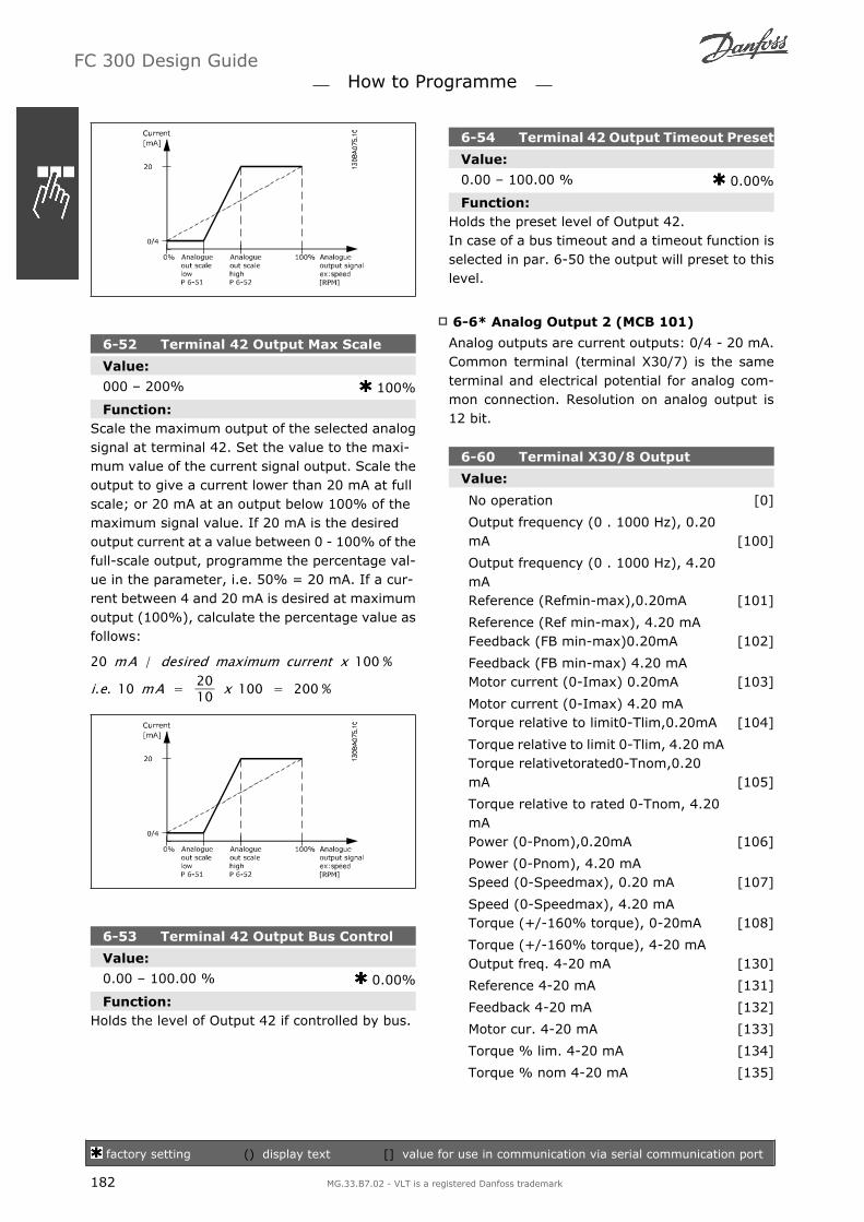
6-52 Terminal 42 Output Max Scale
Value:
000 200% 100%
Function:Scale the maximum output of the selected analogsignal at terminal 42. Set the value to the maxi-mum value of the current signal output. Scale theoutput to give a current lower than 20 mA at fullscale; or 20 mA at an output below 100% of themaximum signal value. If 20 mA is the desiredoutput current at a value between 0 - 100% of thefull-scale output, programme the percentage val-ue in the parameter, i.e. 50% = 20 mA. If a cur-rent between 4 and 20 mA is desired at maximumoutput (100%), calculate the percentage value asfollows:
20 mA / desired maximum current x 100 %
i.e. 10 mA = 2010 x 100 = 200 %
6-53 Terminal 42 Output Bus Control
Value:
0.00 100.00 % 0.00%
Function:Holds the level of Output 42 if controlled by bus.
6-54 Terminal 42 Output Timeout Preset
Value:
0.00 100.00 % 0.00%
Function:Holds the preset level of Output 42.In case of a bus timeout and a timeout function isselected in par. 6-50 the output will preset to thislevel.
6-6* Analog Output 2 (MCB 101)
Analog outputs are current outputs: 0/4 - 20 mA.Common terminal (terminal X30/7) is the sameterminal and electrical potential for analog com-mon connection. Resolution on analog output is12 bit.
6-60 Terminal X30/8 Output
Value:
No operation [0]
Output frequency (0 . 1000 Hz), 0.20mA [100]
Output frequency (0 . 1000 Hz), 4.20mAReference (Refmin-max),0.20mA [101]
Reference (Ref min-max), 4.20 mAFeedback (FB min-max)0.20mA [102]
Feedback (FB min-max) 4.20 mAMotor current (0-Imax) 0.20mA [103]
Motor current (0-Imax) 4.20 mATorque relative to limit0-Tlim,0.20mA [104]
Torque relative to limit 0-Tlim, 4.20 mATorque relativetorated0-Tnom,0.20mA [105]
Torque relative to rated 0-Tnom, 4.20mAPower (0-Pnom),0.20mA [106]
Power (0-Pnom), 4.20 mASpeed (0-Speedmax), 0.20 mA [107]
Speed (0-Speedmax), 4.20 mATorque (+/-160% torque), 0-20mA [108]
Torque (+/-160% torque), 4-20 mAOutput freq. 4-20 mA [130]
Reference 4-20 mA [131]
Feedback 4-20 mA [132]
Motor cur. 4-20 mA [133]
Torque % lim. 4-20 mA [134]
Torque % nom 4-20 mA [135]
FC 300 Design Guide How to Programme
factory setting () display text [] value for use in communication via serial communication port
182 MG.33.B7.02 - VLT is a registered Danfoss trademark

Power 4-20 mA [136]
Speed 4-20 mA [137]
Torque 4-20 mA [138]
Bus Ctrl 0-20 mA [139]
Bus Ctrl 4-20 mA [140]
Bus Ctrl 0-20 mA, Timeout [141]
Bus Ctrl 4-20 mA, Timeout [142]
6-61 Term. X30/8 Output Min Scale
Value:
0.00 - 200 % 0%
Function:Scales the minimum output of the selected analogsignal on terminal X30/8. Scale the minimum val-ue as a percentage of the maximum signal value,i.e. 0 mA (or 0 Hz) is desired at 25% of the max-imum output value and 25% is programmed. Thevalue can never be higher than the correspondingsetting in par. 6-62 if value is below 100%.This parameter is active when option module MCB101 is mounted in the frequency converter.
6-62 Term. X30/8 Output Max Scale
Value:
0.00 - 200 % 100%
Function:Scales the maximum output of the selected ana-log signal on terminal X30/8. Scale the value tothe desired masimum value of the current signaloutput. Scale the output to give a lower currentthan 20 mA at full scale or 20 mA at an outputbelow 100% of the maximum signal value. If 20mA is the desired output current at a value be-tween 0 - 100% of the ful-scale output, programthe percentage value in the parameter, i.e. 50%= 20 mA. If a current between 4 and 20 MA is de-sired at maximum output (100%), calculate thepercentage value as follows:
20 mA / desired maximum current x 100 %
i.e. 10 mA = 2010 x 100 = 200 %
FC 300 Design Guide How to Programme
factory setting () display text [] value for use in communication via serial communication port
MG.33.B7.02 - VLT is a registered Danfoss trademark 183
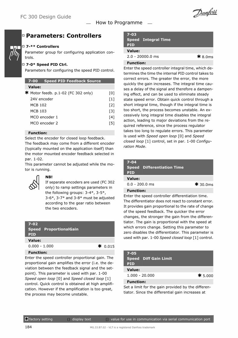
Parameters: Controllers
7-** Controllers
Parameter group for configuring application con-trols.
7-0* Speed PID Ctrl.
Parameters for configuring the speed PID control.
7-00 Speed PID Feedback Source
Value:
Motor feedb. p.1-02 (FC 302 only) [0]
24V encoder [1]
MCB 102 [2]
MCB 103 [3]
MCO encoder 1 [4]
MCO encoder 2 [5]
Function:Select the encoder for closed loop feedback.The feedback may come from a different encoder(typically mounted on the application itself) thanthe motor mounted encoder feedback selected inpar. 1-02.This parameter cannot be adjusted while the mo-tor is running.
NB!If separate encoders are used (FC 302only) to ramp settings parameters inthe following groups: 3-4*, 3-5*,3-6*, 3-7* and 3-8* must be adjustedaccording to the gear ratio betweenthe two encoders.
7-02SpeedPID
ProportionalGain
Value:
0.000 - 1.000 0.015
Function:Enter the speed controller proportional gain. Theproportional gain amplifies the error (i.e. the de-viation between the feedback signal and the set-point). This parameter is used with par. 1-00Speed open loop [0] and Speed closed loop [1]control. Quick control is obtained at high amplifi-cation. However if the amplification is too great,the process may become unstable.
7-03SpeedPID
Integral Time
Value:
2.0 - 20000.0 ms 8.0ms
Function:Enter the speed controller integral time, which de-termines the time the internal PID control takes tocorrect errors. The greater the error, the morequickly the gain increases. The integral time cau-ses a delay of the signal and therefore a dampen-ing effect, and can be used to eliminate steadystate speed error. Obtain quick control through ashort integral time, though if the integral time istoo short, the process becomes unstable. An ex-cessively long integral time disables the integralaction, leading to major deviations from the re-quired reference, since the process regulatortakes too long to regulate errors. This parameteris used with Speed open loop [0] and Speedclosed loop [1] control, set in par. 1-00 Configu-ration Mode.
7-04SpeedPID
Differentiation Time
Value:
0.0 - 200.0 ms 30.0ms
Function:Enter the speed controller differentiation time.The differentiator does not react to constant error.It provides gain proportional to the rate of changeof the speed feedback. The quicker the errorchanges, the stronger the gain from the differen-tiator. The gain is proportional with the speed atwhich errors change. Setting this parameter tozero disables the differentiator. This parameter isused with par. 1-00 Speed closed loop [1] control.
7-05SpeedPID
Diff Gain Limit
Value:
1.000 - 20.000 5.000
Function:Set a limit for the gain provided by the differen-tiator. Since the differential gain increases at
FC 300 Design Guide How to Programme
factory setting () display text [] value for use in communication via serial communication port
184 MG.33.B7.02 - VLT is a registered Danfoss trademark

higher frequencies, limiting the gain may be use-ful. For example, set up a pure D-link at low fre-quencies and a constant D-link at higher frequen-cies. This parameter is used with par. 1-00 Speedclosed loop [1] control.
7-06 Speed PID Lowpass Filter Time
Value:
1.0 - 100.0 ms 10.0ms
Function:Set a time constant for the speed control low-passfilter. The low-pass filter improves steady-stateperformance and dampens oscillations on thefeedback signal. This is an advantage if there is agreat amount on noise in the SYSTEM, see illus-tration below. For example, if a time constant (τ)of 100 ms is programmed, the cut-off frequencyfor the low-pass filter will be 1/0.1= 10 RAD/sec.,corresponding to (10/2 x p) = 1.6 Hz. The PIDregulator only regulates a feedback signal thatvaries by a frequency of less than 1.6 Hz. If thefeedback signal varies by a higher frequency than1.6 Hz, the PID regulator does not react.Note that severe filtering can be detrimental todynamic performance.This parameter is used with par. 1-00 Speedclosed loop [1] and Torque [2] control.
7-08 Speed PID Feed Forward Factor
Value:
0 - 500% 0%
Function:The reference signal bypasses the speed control-ler by the amount specified. This feature increases
the dynamic performance of the speed controlloop.
7-2* Process Ctrl. Feedb.
Select the feedback sources for the Process PIDControl, and how this feedback should be handled.
7-20 Process CL Feedback 1 Source
Value:
No function [0]
Analog input 53 [1]
Analog input 54 [2]
Frequency input 29 (FC 302 only) [3]
Frequency input 33 [4]
Bus feedback 1 [5]
Bus feedback 2 [6]
Analog input X30/11 [7]
Analog input X30/12 [8]
Function:The effective feedback signal is made up of thesum of up to two different input signals.Select which frequency converter input should betreated as the source of the first of these signals.The second input signal is defined in par. 7-22.
7-22 Process CL Feedback 2 Source
Value:
No function [0]
Analog input 53 [1]
Analog input 54 [2]
Frequency input 29 (FC 302 only) [3]
Frequency input 33 [4]
Bus feedback 1 [5]
Bus feedback 2 [6]
Analog input X30/11 [7]
Analog input X30/12 [8]
Function:The effective feedback signal is made up of thesum of up to two different input signals. Selectwhich frequency converter input should be treatedas the source of the second of these signals. Thefirst input signal is defined in par. 7-21.
FC 300 Design Guide How to Programme
factory setting () display text [] value for use in communication via serial communication port
MG.33.B7.02 - VLT is a registered Danfoss trademark 185

7-3* Process PID Ctrl.
Parameters for configuring the Process PID con-trol.
7-30Process PID Normal/ Inverse Con-trol
Value:
Normal [0]
Inverse [1]
Function:Select Normal [0] to set the process control to in-crease the output frequency.Select Inverse [1] to set the process control to re-duce the output frequency. Normal and inversecontrol are implemented by introducing a differ-ence between the reference signal and the feed-back signal.
7-31 Process PID Anti Windup
Value:
Off [0]
On [1]
Function:Select Off [0] to cease regulation of an error whenthe output frequency can no longer be adjusted.Select On [1] to continue regulation of an erroreven when the output frequency cannot be in-creased or decreased.
7-32 Process PID Start Speed
Value:
0 - 6000 RPM 0RPM
Function:Enter the motor speed to be attained as a startsignal for commencement of PID control. Whenthe power is switched on, the frequency converterwill commence ramping and then operate underspeed open loop control. Thereafter, when theProcess PID start speed is reached, the frequencyconverter will change over to Process PID control.
7-33 Process PID Proportional Gain
Value:
0.00 - 10.00 N/A 0.01N/A
Function:Enter the PID proportional gain. The proportionalgain multiplies the error between the set point andthe feedback signal.
7-34 Process PID Integral Time
Value:
0.01 - 10000.00 10000.00s
Function:Enter the PID integral time. The integrator pro-vides an increasing gain at a constant error be-tween the set point and the feedback signal. Theintegral time is the time needed by the integratorto reach the same gain as the proportional gain.
7-35 Process PID Differentiation Time
Value:
0.00 - 10.00 s 0.00s
Function:Enter the PID differentiation time. The differen-tiator does not react to a constant error, but pro-vides a gain only when the error changes. Theshorter the PID differentiation time, the strongerthe gain from the differentiator.
7-36 Process PID Diff. Gain Limit
Value:
1.0 - 50.0 N/A 5.0N/A
Function:Enter a limit for the differentiator gain (DG). Ifthere is no limit, the DG will increase when thereare fast changes. Limit the DG to obtain a puredifferentiator gain at slow changes and a constantdifferentiator gain where fast changes occur.
7-38 Process PID Feed Forward Factor
Value:
0 - 500% 0%
Function:Enter the PID feed forward (FF) factor. The FF fac-tor sends a constant fraction of the reference sig-nal to bypass the PID control, so the PID controlonly affects the remaining fraction of the controlsignal. Any change to this parameter will thus af-fect the motor speed. When the FF factor is acti-
FC 300 Design Guide How to Programme
factory setting () display text [] value for use in communication via serial communication port
186 MG.33.B7.02 - VLT is a registered Danfoss trademark

vated it provides less overshoot, and high dynam-ics when changing the set point. Par. 7-38 isactive when par. 1-00 Configuration Mode is setto [3] Process.
7-39 On Reference Bandwidth
Value:
0 - 200% 5%
Function:Enter the On Reference bandwidth. When the PIDControl Error (the difference between the refer-ence and the feedback) is less than the set valueof this parameter the On Reference status bit ishigh, i.e. =1.
FC 300 Design Guide How to Programme
MG.33.B7.02 - VLT is a registered Danfoss trademark 187

Parameters: Communica-tions and Options
8-** Comm. and Options
Parameter group for configuring communicationsand options.
8-0* General Settings
General settings for communications and options.
8-01 Control Site
Value:
Digital and ctrl. word [0]
Digital only [1]
Control word only [2]
Function:Select Digital and ctrl. word [0] for control usingboth digital input and control word.Select Digital only [1] for control using digital in-puts only.Select Control word only [2] for control using con-trol word only.The setting in this parameter overrules the set-tings in par. 8-50 to 8-56.
8-02 Control Word Source
Value:
None [0]
FC RS485 [1]
FC USB [2]
Option A [3]
Option B [4]
Option C0 [5]
Option C1 [6]
Function:Select the source of the control word: one of twoserial interfaces or four installed options. Duringinitial power-up, the frequency converter auto-matically sets this parameter to Option A [3] if itdetects a valid fieldbus option installed in slot A.If the option is removed, the frequency converterdetects a change in the configuration, sets par.8-02 back to default setting FC RS485, and thefrequency converter then trips. If an option is in-stalled after initial power-up, the setting of par.
8-02 will not change but the frequency converterwill trip and display: Alarm 67 Option Changed.This parameter cannot be adjusted while the mo-tor is running.
8-03 Control Word Timeout Time
Value:
0.1 - 18000.0 s 1.0s
Function:Enter the maximum time expected to pass be-tween the reception of two consecutive telegrams.If this time is exceeded, it indicates that the serialcommunication has stopped. The function selec-ted in par. 8-04 Control Word Time-out Functionwill then be carried out. The time-out counter istriggered by a valid control word.
8-04 Control Word Timeout Function
Value:
Off [0]
Freeze Output [1]
Stop [2]
Jogging [3]
Max. Speed [4]
Stop and trip [5]
Select set-up 1 [7]
Select set-up 2 [8]
Select set-up 3 [9]
Select set-up 4 [10]
Function:Select the time-out function. The time-out func-tion activates when the control word fails to beupdated within the time period specified in par.8-03 Control Word Time-out Time.
- Off [0]: Resume control via serial bus(Fieldbus or standard) using the most re-cent control word.
- Freeze output [1]: Freeze output frequen-cy until communication resumes.
- Stop [2]: Stop with auto restart whencommunication resumes.
- Jogging [3]: Run the motor at JOG fre-quency until communication resumes.
FC 300 Design Guide How to Programme
factory setting () display text [] value for use in communication via serial communication port
188 MG.33.B7.02 - VLT is a registered Danfoss trademark

- Max. freq. [4]: Run the motor at maxi-mum frequency until communication re-sumes.
- Stop and trip [5]: Stop the motor, thenreset the frequency converter in order torestart: via the fieldbus, via the reset but-ton on the LCP or via a digital input.
- Select set-up 1-4 [7] - [10]: This optionchanges the set-up upon reestablishmentof communication following a control wordtime-out. If communication resumescausing the time-out situation to disap-pear, par. 8-05 End-of-time-out Functiondefines whether to resume the set-upused before the time-out or to retain theset-up endorsed by the time-out function.Note the following configuration requiredin order to change the set-up after a time-out: Set Par. 0-10 Active set-up to Multiset-up [9], and select the relevant link inpar. 0-12 This Set-up Linked To.
8-05 End-of-Timeout Function
Value:
Hold set-up [0]
Resume set-up [1]
Function:Select the action after receiving a valid controlword following a time-out. This parameter is ac-tive only when par. 8-04 is set to Set-up 1-4.Hold: The frequency converter retains the set-upselected in par. 8-04 and displays a warning, untilpar. 8-06 toggles. Then the frequency converterresumes its original set-up.Resume: The frequency converter resumes theset-up active prior to the time-out.
8-06 Reset Control Word Timeout
Value:
Do not reset [0]
Do reset [1]
Function:Select Do reset [1] to return the frequency con-verter to the original set-up following a controlword time-out. When the value is set to Do reset
[1], the frequency converter performs the resetand then immediately reverts to the Do not reset[0] setting.Select Do not reset [0] to retain the set-up speci-fied in par. 8-04, Select setup 1-4 following acontrol word time-out.This parameter is active only when Hold set-up [0]has been selected in par. 8-05 End-of-Time-outFunction.
8-07 Diagnosis Trigger
Value:
Disable [0]
Trigger on alarms [1]
Trigger alarms/warn. [2]
Function:This parameter enables and controls the frequen-cy converter diagnosis function and permits ex-pansion of the diagnosis data to 24 byte.
NB!It relates only to Profibus.
- Disable [0]: Do not send extended diag-nosis data even if they appear in the fre-quency converter.
- Trigger on alarms [1]: Send extended di-agnosis data when one or more alarmsappear in alarm par. 16-90 or 9-53.
- Trigger alarms/warn. [2]: Send extendeddiagnosis data if one or more alarms orwarnings appear in alarm par. 16-90,9-53, or warning par. 16-92.
The content of the extended diagnosis frame is asfollows:
FC 300 Design Guide How to Programme
factory setting () display text [] value for use in communication via serial communication port
MG.33.B7.02 - VLT is a registered Danfoss trademark 189

Byte Content Description0 - 5 Standard DP Di-
agnose DataStandard DP Diagnose Data
6 PDU length xx Header of extended diagnos-tic data
7 Status type =0x81
Header of extended diagnos-tic data
8 Slot = 0 Header of extended diagnos-tic data
9 Status info = 0 Header of extended diagnos-tic data
10 - 13 VLT par. 16-92 VLT warning word14 - 17 VLT par. 16-03 VLT status word18 - 21 VLT par. 16-90 VLT alarm word22 - 23 VLT par. 9-53 Communication warning word
(Profibus)
Enabling diagnosis may cause increased bus traf-fic. Diagnosis functions are not supported by allfieldbus types.
8-1* Ctrl. Word Settings
Parameters for configuring the option controlword profile.
8-10 Control Word Profile
Value:
FC profile [0]
PROFIdrive profile [1]
ODVA [5]
CANopen DSP 402 [7]
Function:Select the interpretation of the control and statuswords corresponding to the installed fieldbus. On-ly the selections valid for the fieldbus installed inslot A will be visible in the LCP display.For guidelines in selection of FC profile [0] andPROFIdrive profile [1] please refer to the Serialcommunication via RS 485 Interface section in theHow to Programmechapter.For additional guidelines in the selection of PRO-FIdrive profile [1], ODVA [5] and CANopen DSP402 [7], please refer to the Operating Instructionsfor the installed fieldbus.
8-13 Configurable Status Word STW
Value:
Bit 12 [12]
Bit 13 [13]
Bit 14 [14]
Bit 15 [15]
Function:This parameter enables configuration of bit 12 15 in the status word.Profile Default [1]: The function on the bit cor-responds to the profile default selected in par.8-10.Alarm 68 Only [2]: The bit is only set in case ofan Alarm 68.Trip except Alarm 68 [3]: The bit is set in caseof a trip, except if the trip is executed by an Alarm68.T37 DI status [16]: The bit indicates the statusof terminal 37.0 indicates T37 is low (safe stop)1 indicates T37 is high (normal)
8-3* FC Port Settings
Parameters for configuring the FC Port.
8-30 Protocol
Value:
FC [0]
FC MC [1]
Function:Select the protocol for the FC (standard) port.
8-31 Address
Value:
1 - 126 1
Function:Enter the address for the FC (standard) port.Valid range: 1 - 126.
8-32 FC Port Baud Rate
Value:
2400 Baud [0]
4800 Baud [1]
9600 Baud [2]
19200 Baud [3]
38400 Baud [4]
115200 Baud [7]
Function:Baud rate selection for the FC (standard) port.
FC 300 Design Guide How to Programme
factory setting () display text [] value for use in communication via serial communication port
190 MG.33.B7.02 - VLT is a registered Danfoss trademark

8-35 Minimum Response Delay
Value:
1 - 500 ms 10ms
Function:Specify the minimum delay time between receiv-ing a request and transmitting a response. This isused for overcoming modem turnaround delays.
8-36 Max Response Delay
Value:
1 - 10000 ms 5000ms
Function:Specify the maximum permissible delay time be-tween transmitting a request and receiving a re-sponse. Exceeding this delay time will causecontrol word time-out.
8-37 Max Inter-Char Delay
Value:
0 - 30 ms 25ms
Function:Specify the maximum permissible time intervalbetween receipt of two bytes. This parameter ac-tivates time-out if transmission is interrupted.This parameter is active only when par. 8-30 is setto FC MC [1] protocol.
8-40 FC MC Protocol Set
Value:
Standard Telegram 1 [1]
Custom Telegram [200]
Function:Enables use of freely configurable telegrams orstandard telegrams for the FC port.
8-5* Digital/Bus
Parameters for configuring the control word Digi-tal/Bus merging.
8-50 Coasting Select
Value:
Digital input [0]
Bus [1]
Logic AND [2]
Logic OR [3]
Function:Select control of the coasting function via the ter-minals (digital input) and/or via the bus.
NB!This parameter is active only whenpar. 8-01 Control Site is set to [0] Dig-ital and control word.
8-51 Quick Stop Select
Value:
Digital input [0]
Bus [1]
Logic AND [2]
Logic OR [3]
Function:Select control of the Quick Stop function via theterminals (digital input) and/or via the bus.
NB!This parameter is active only whenpar. 8-01 Control Site is set to [0] Dig-ital and control word.
8-52 DC Brake Select
Value:
Digital input [0]
Bus [1]
Logic AND [2]
Logic OR [3]
Function:Select control of the DC brake via the terminals(digital input) and/or via the fieldbus.
NB!This parameter is active only whenpar. 8-01 Control Site is set to [0] Dig-ital and control word.
8-53 Start Select
Value:
Digital input [0]
Bus [1]
FC 300 Design Guide How to Programme
factory setting () display text [] value for use in communication via serial communication port
MG.33.B7.02 - VLT is a registered Danfoss trademark 191

Logic AND [2]
Logic OR [3]
Function:Select control of the frequency converter startfunction via the terminals (digital input) and/orvia the fieldbus.Select Bus [1], to activate the Start command viathe serial communication port or fieldbus option.Select Logic AND [2] to activate the Start com-mand via the fieldbus/serial communication port,AND additionally via one of the digital inputs.Select Logic OR [3] to activate the Start commandvia the fieldbus/serial communication port OR viaone of the digital inputs.
NB!This parameter is active only whenpar. 8-01 Control Site is set to [0] Dig-ital and control word.
8-54 Reversing Select
Value:
Digital input [0]
Bus [1]
Logic AND [2]
Logic OR [3]
Function:Select control of the frequency converter reversefunction via the terminals (digital input) and/orvia the fieldbus.Select Bus [1], to activate the Reverse commandvia the serial communication port or fieldbus op-tion.Select Logic AND [2] to activate the Reverse com-mand via the fieldbus/serial communication port,AND additionally via one of the digital inputs.Select Logic OR [3] to activate the Reverse com-mand via the fieldbus/serial communication portOR via one of the digital inputs.
NB!This parameter is active only whenpar. 8-01 Control Site is set to [0] Dig-ital and control word.
8-55 Set-up Select
Value:
Digital input [0]
Bus [1]
Logic AND [2]
Logic OR [3]
Function:Select control of the frequency converter set-upselection via the terminals (digital input) and/orvia the fieldbus.Select Bus [1], to activate the set-up selection viathe serial communication port or fieldbus option.Select Logic AND [2] to activate the set-up selec-tion via the fieldbus/serial communication port,AND additionally via one of the digital inputs.Select Logic OR [3] to activate the set-up selec-tion via the fieldbus/serial communication port ORvia one of the digital inputs.
NB!This parameter is active only whenpar. 8-01 Control Site is set to [0] Dig-ital and control word.
8-56 Preset Reference Select
Value:
Digital input [0]
Bus [1]
Logic AND [2]
Logic OR [3]
Function:Select control of the frequency converter PresetReference selection via the terminals (digital in-put) and/or via the fieldbus.Select Bus [1], to activate the Preset Referenceselection via the serial communication port orfieldbus option.Select Logic AND [2] to activate the Preset Refer-ence selection via the fieldbus/serial communica-tion port, AND additionally via one of the digitalinputs.Select Logic OR [3] to activate the Preset Refer-ence selection via the fieldbus/serial communica-tion port OR via one of the digital inputs.
NB!This parameter is active only whenpar. 8-01 Control Site is set to [0] Dig-ital and control word.
8-9* Bus Jog
Parameters for configuring the Bus Jog.
FC 300 Design Guide How to Programme
factory setting () display text [] value for use in communication via serial communication port
192 MG.33.B7.02 - VLT is a registered Danfoss trademark

8-90 Bus Jog 1 Speed
Value:
0 - par. 4-13 RPM 100RPM
Function:Enter the jog speed. This is a fixed jog speed ac-tivated via the serial port or fieldbus option.
8-91 Bus Jog 2 Speed
Value:
0 - par. 4-13 RPM 200RPM
Function:Enter the jog speed. This is a fixed jog speed ac-tivated via the serial port or fieldbus option.
FC 300 Design Guide How to Programme
MG.33.B7.02 - VLT is a registered Danfoss trademark 193

Parameters: Profibus
9-** Profibus
Parameter group for all Profibus-specific parame-ters.
9-00 Setpoint
Value:
0-65535 0
Function:This parameter receives cyclical reference from aMaster Class 2. If the control priority is set to Mas-ter Class 2, the reference for the frequency con-verter is taken from this parameter, whereas thecyclical reference will be ignored.
9-07 Actual Value
Value:
0-65535 0
Function:This parameter deliveres the MAV for a MasterClass 2. The parameter is valid if the control pri-ority is set to Master Class 2.
9-15 PCD Write ConfigurationArray [10]
Value:
None
3-02 Minimum Reference
3-03 Maximum Reference
3-12 Catch Up/Slow Down Value
3-41 Ramp 1 Ramp Up Time
3-42 Ramp 1 Ramp Down Time
3-51 Ramp 2 Ramp Up Time
3-52 Ramp 2 Ramp Down Time
3-80 Jog Ramp Time
3-81 Quick Stop Ramp Time
4-11 Motor Speed Low Limit [RPM]
4-13 Motor Speed High Limit [RPM]
4-16 Torque Limit Motor Mode
4-17 Torque Limit Generator Mode
7-28 Minimum Feedback
7-29 Maximum Feedback
8-90 Bus Jog 1 Speed
8-91 Bus Jog 2 Speed
16-80 Fieldbus CTW 1
16-82 Fieldbus REF 1
34-01 PCD 1 Write to MCO
34-02 PCD 2 Write to MCO
34-03 PCD 3 Write to MCO
34-04 PCD 4 Write to MCO
34-05 PCD 5 Write to MCO
34-06 PCD 6 Write to MCO
34-07 PCD 7 Write to MCO
34-08 PCD 8 Write to MCO
34-09 PCD 9 Write to MCO
34-10 PCD 10 Write to MCO
Function:Select the parameters to be assigned to PCD 3 to10 of the telegrams. The number of availablePCDs depends on the telegram type. The values inPCD 3 to 10 will then be written to the selectedparameters as data values. Alternatively, specifya standard Profibus telegram in par. 9-22.
9-16 PCD Read Configuration
Array [10]
Value:
None
16-00 Control Word
16-01 Reference [Unit]
16-02 Reference %
16-03 Status Word
16-04 Main Actual Value [Unit]
16-05 Main Actual Value [%]
16-09 Custom Readout
16-10 Power [kW]
16-11 Power [hp]
16-12 Motor Voltage
16-13 Frequency
16-14 Motor Current
16-16 Torque
16-17 Speed [RPM]
16-18 Motor Thermal
16-19 KTY Sensor Temperature
16-21 Phase Angle
16-30 DC Link Voltage
16-32 Brake Energy / s
FC 300 Design Guide How to Programme
factory setting () display text [] value for use in communication via serial communication port
194 MG.33.B7.02 - VLT is a registered Danfoss trademark

16-33 Brake Energy / 2 min
16-34 Heatsink Temp.
16-35 Inverter Thermal
16-38 SL Control State
16-39 Control Card Temp.
16-50 External Reference
16-51 Pulse Reference
16-52 Feedback [Unit]
16-53 Digi Pot Reference
16-60 Digital Input
16-61 Terminal 53 Switch Setting
16-62 Analog Input 53
16-63 Terminal 54 Switch Setting
16-64 Analog Input 54
16-65 Analog Output 42 [mA]
16-66 Digital Output [bin]
16-67 Freq. Input #29 [Hz]
16-68 Freq. Input #33 [Hz]
16-69 Pulse Output #27 [Hz]
16-70 Pulse Output #29 [Hz]
16-71 Pulse Output [bin]
16-84 Comm Option STW [Binary]
16-85 FC port CTW 1 Signal
16-90 Alarm Word
16-91 Alarm Word 2
16-92 Warning Word
16-93 Warning Word 2
16-94 Extended Status Word
16-95 Extended Status Word 2
34-21 PCD 1 Read from MCO
34-22 PCD 2 Read from MCO
34-23 PCD 3 Read from MCO
34-24 PCD 4 Read from MCO
34-25 PCD 5 Read from MCO
34-26 PCD 6 Read from MCO
34-27 PCD 7 Read from MCO
34-28 PCD 8 Read from MCO
34-29 PCD 9 Read from MCO
34-30 PCD 10 Read from MCO
34-40 Digital Inputs
34-41 Digital Outputs
34-50 Actual Position
34-51 Commanded Position
34-52 Actual Master Position
34-53 Slave Index Position
34-54 Master Index Position
34-55 Curve Position
34-56 Track Error
34-57 Synchronizing Error
34-58 Actual Velocity
34-59 Actual Master Velocity
34-60 Synchronizin Status
34-61 Axis Status
34-62 Program Status
Function:Select the parameters to be assigned to PCD 3 to10 of the telegrams. The number of availablePCDs depends on the telegram type. PCDs 3 to 10contain the actual data values of the selected pa-rameters. For standard Profibus telegrams, seepar. 9-22.
9-18 Node Address
Value:
0 - 126 126
Function:Enter the station address in this parameter or al-ternatively in the hardware switch. In order toadjust the station address in par. 9-18, the hard-ware switch must be set to 126 or 127 (i.e. allswitches set to on). Otherwise this parameterwill display the actual setting of the switch.
9-22 Telegram Selection
Value:
Standard telegram 1 [1]
PPO 1 [101]
PPO 2 [102]
PPO 3 [103]
PPO 4 [104]
PPO 5 [105]
PPO 6 [106]
PPO 7 [107]
PPO 8 [108]
Function:Read only.
Displays the Profibus telegram configuration.
FC 300 Design Guide How to Programme
factory setting () display text [] value for use in communication via serial communication port
MG.33.B7.02 - VLT is a registered Danfoss trademark 195

9-23 Parameters for Signals
Array [1000]Read only
Function:This parameter contains a list of signals availablefor selection in par. 9-15 and 9-16.
9-27 Parameter Edit
Value:
Disabled [0]
Enabled [1]
Function:Parameters can be edited via Profibus, the stand-ard RS485 interface, or the LCP.Select Disabled [0] to disable editing via Profibus.
9-28 Process Control
Value:
Disable [0]
Enable cyclic master [1]
Function:Process control (setting of Control Word, speedreference, and process data) is possible via eitherProfibus or standard fieldbus but not both simul-taneously. Local control is always possible via theLCP. Control via process control is possible via ei-ther terminals or fieldbus depending on the set-tings in par. 8-50 to 8-56.Select Disable [0] to disable process control viaProfibus, and enable process control via standardfieldbus or Profibus Master class 2.Select Enable cyclic master [1] to enable processcontrol via Profibus Master Class 1, and disableprocess control via standard fieldbus or ProfibusMaster class 2.
9-44 Fault Message Counter
Value:
0-65535 0
Function:This parameter displays the number of errorevents stored in par. 9-45 and 9-47. The maxi-mum buffer capacity is eight error events. The
buffer and counter are set to 0 upon reset or pow-er-up.
9-45 Fault Code
Value:
0 - 0 0
Function:This buffer contains the alarm word for all alarmsand warnings that have occurred since last resetor power-up. The maximum nuffer capacity iseight error events.
9-47 Fault Number
Value:
0 - 0 0
Function:This buffer contains the alarm number (e.g. 2 forlive zero error, 4 for mains phase loss) for allalarms and warnings that have occurred since lastreset or power-up. The maximum buffer capacityis eight error events.
9-52 Fault Situation Counter
Value:
0 - 1000 0
Function:This parameter displays the number of errorevents which have occurred since last reset ofpower-up.
9-53 Profibus Warning Word
Value:
Read only
Bit: Meaning:0 Connection with DP-master is not1 Not used2 FDL (Field-bus Data link Layer) is not ok3 Clear data command received4 Actual value is not updated5 Baudrate search6 PROFIBUS ASIC is not transmitting7 Initializing of PROFIBUS is not ok8 Drive is tripped9 Internal CAN error10 Wrong configuration data from PLC11 Wrong ID sent by PLC12 Internal error occured13 Not configured14 Timeout active15 Warning 34 active
FC 300 Design Guide How to Programme
factory setting () display text [] value for use in communication via serial communication port
196 MG.33.B7.02 - VLT is a registered Danfoss trademark

Function:This parameter displays Profibus communicationwarnings. Please refer to the Profibus OperatingInstructions for further information.
9-63 Actual Baud Rate
Value:
Read only
9.6 kbit/s [0]
19.2 kbit/s [1]
93.75 kbit/s [2]
187.5 kbit/s [3]
500 kbit/s [4]
1500 kbit/s [6]
3000 kbit/s [7]
6000 kbit/s [8]
12000 kbit/s [9]
31.25 kbit/s [10]
45.45 kbit/s [11]
No baud rate found [255]
Function:This parameter displays the actual Profibus baudrate. The Profibus Master automatically sets thebaud rate.
9-64 Device Identification
Value:
0 - 0 0
Function:This parameter displays the device identification.Please refer to the Operating Instructions for Pro-fibus, MG33CXYY for further explanation.
9-65 Profile Number
Value:
Read only
0 - 0 0
Function:This parameter contains the profile identification.Byte 1 contains the profile number and byte 2 theversion number of the profile.
NB!This parameter is not visible via LCP.
9-67 Control Word 1
Value:
0-65535 0
Function:This parameter accepts the Control Word from aMaster Class 2 in the same format as PCD 1.
9-68 Status Word 1
Value:
0-65535 0
Function:This parameter delivers the Status Word for aMaster Class 2 in the same format as PCD 2.
9-70 Edit Set-up
Value:
Factory setup [0]
Setup 1 [1]
Setup 2 [2]
Setup 3 [3]
Setup 4 [4]
Active setup [9]
Function:Select the set-up to be edited.Select Set-up 1-4 [1]-[4] to edit a specific set-up.Select Active set-up [9] to follow the active set-upselected in par. 0-10.Select Factory set-up [0] for default data. Thisoption can be used as a data source to return theother set-ups to a known state.This parameter is unique to LCP and fieldbuses.See also par. 0-11 Edit set-up.
9-71 Save Data Values
Value:
Off [0]
Store edit setup [1]
Store all set-ups [2]
FC 300 Design Guide How to Programme
factory setting () display text [] value for use in communication via serial communication port
MG.33.B7.02 - VLT is a registered Danfoss trademark 197

Function:Parameter values changed via Profibus are notautomatically stored in non-volatile memory. Usethis parameter to activate a function that storesparameter values in the EEPROM non-volatilememory, so changed parameter values will be re-tained at power-down.Select Off [0] to deactivate the non-volatile stor-age function.Select Store edit setup [1] to store all parametervalues in the set-up selected in par. 9-70 in thenon-volatile memory. The selection returns to Off[0] when all values have been stored.Select Store all set-ups [2] to store all parametervalues for all set-ups in the non-volatile memory.The selection returns to Off [0] when all parame-ter values have been stored.
9-72 Drive Reset
Value:
No action [0]
Power-on reset [1]
Comm. option reset [3]
Function:Select Power-on reset [1] to reset the frequencyconverter upon power-up, as for power-cycle.Select Comm. option reset [3] to reset the Profi-bus option only, useful after changing certain set-tings in parameter group 9-**, e.g. par. 9-18.When reset, the frequency converter disappearsfrom the fieldbus, which may cause a communi-cation error from the master.
9-80 Defined Parameters (1)
Array [116]
Value:
No LCP access
Read only
0 - 115 0
Function:This parameter displays a list of all the definedfrequency converter parameters available for Pro-fibus.
9-81 Defined Parameters (2)
Array [116]
Value:
No LCP access
Read only
0 - 115 0
Function:This parameter displays a list of all the definedfrequency converter parameters available for Pro-fibus.
9-82 Defined Parameters (3)
Array [116]
Value:
No LCP access
Read only
0 - 115 0
Function:This parameter displays a list of all the definedfrequency converter parameters available for Pro-fibus.
9-83 Defined Parameters (4)
Array [116]
Value:
No LCP access
Read only
0 - 115 0
Function:This parameter displays a list of all the definedfrequency converter parameters available for Pro-fibus.
9-84 Defined Parameters (5)
Value:
Array [116]
No LCP access
Read only
0 - 115 0
FC 300 Design Guide How to Programme
factory setting () display text [] value for use in communication via serial communication port
198 MG.33.B7.02 - VLT is a registered Danfoss trademark

Function:This parameter displays a list of all the definedfrequency converter parameters available for Pro-fibus.
9-90 Changed Parameters (1)
Array [116]
Value:
No LCP access
Read only
0 - 115 0
Function:This parameter displays a list of all the frequencyconverter parameters deviating from default set-ting.
9-91 Changed Parameters (2)
Array [116]
Value:
No LCP access
Read only
0 - 115 0
Function:This parameter displays a list of all the frequencyconverter parameters deviating from default set-ting.
9-92 Changed Parameters (3)
Array [116]
Value:
No LCP access
Read only
0 - 115 0
Function:This parameter displays a list of all the frequencyconverter parameters deviating from default set-ting.
9-94 Changed Parameters (5)
Array [116]
Value:
No LCP access
Read only
0 - 115 0
Function:This parameter displays a list of all the frequencyconverter parameters deviating from default set-ting.
FC 300 Design Guide How to Programme
factory setting () display text [] value for use in communication via serial communication port
MG.33.B7.02 - VLT is a registered Danfoss trademark 199

Parameters: DeviceNet CANFieldbus
10-** DeviceNet CAN Fieldbus
Parameter group for DeviceNet CAN fieldbus pa-rameters.
10-0* Common Settings
Parameter group for configuring common settingsfor CAN fieldbus options.
10-00 CAN Protocol
Value:
CANopen [0]
DeviceNet [1]
Function:View the active CAN protocol.
NB!The options depend on installed op-tion.
10-01 Baud Rate Select
Value:
10 Kbps [16]
20 Kbps [17]
50 Kbps [18]
100 Kbps [19]
125 Kbps [20]
250 Kbps [21]
500 Kbps [22]
Function:Select the fieldbus transmission speed. The selec-tion must correspond to the transmission speed ofthe master and the other fieldbus nodes.
10-02 MAC ID
Value:
0 - 127 63
Function:Selection of station address. Every station con-nected to the same network must have an unam-biguous address.
10-05 Readout Transmit Error Counter
Value:
0 - 255 0
Function:View the number of CAN control transmission er-rors since the last power-up.
10-06 Readout Receive Error Counter
Value:
0 - 255 0
Function:View the number of CAN control receipt errorssince the last power-up.
10-07 Readout Bus Off Counter
Value:
0 - 255 0
Function:View the number of Bus Off events since the lastpower-up.
10-1* DeviceNet
Parameters specific to the DeviceNet fieldbus.
10-10 Process Data Type Selection
Value:
Instance 100/150 [0]
Instance 101/151 [1]
Instance 20/70 [2]
Instance 21/71 [3]
Function:Select the Instance (telegram) for data transmis-sion. The Instances available are dependent uponthe setting of par. 8-10 Control Word Profile.When par. 8-10 is set to [0] FC profile, par. 10-10options [0] and [1] are available.When par. 8-10 is set to [5] ODVA, par. 10-10options [2] and [3] are available.Instances 100/150 and 101/151 are Danfoss-spe-cific. Instances 20/70 and 21/71 are ODVA-spe-cific AC Drive profiles.For guidelines in telegram selection, please referto the DeviceNet Operating Instructions.Note that a change to this parameter will be exe-cuted immediately.
FC 300 Design Guide How to Programme
factory setting () display text [] value for use in communication via serial communication port
200 MG.33.B7.02 - VLT is a registered Danfoss trademark

10-11 Process Data Config Write
Value:
0 None
3-02 Minimum reference
3-03 Maximum reference
3-12 Catch up/slow down value
3-41 Ramp 1 ramp up time
3-42 Ramp 1 ramp down time
3-51 Ramp 2 ramp up time
3-52 Ramp 2 ramp down time
3-80 Jog ramp time
3-81 Quick stop ramp time
4-11 Motor speed low limit (RPM)
4-13 Motor speed high limit (RPM)
4-16 Torque limit motor mode
4-17 Torque limit generator mode
7-28 Minimum Feedback
7-29 Maximum Feedback
8-90 Bus Jog 1 Speed
8-91 Bus Jog 2 Speed
16-80 Fieldbus CTW 1 (Fixed)
16-82 Fieldbus REF 1 (Fixed)
34-01 PCD 1 Write to MCO
34-02 PCD 2 Write to MCO
34-03 PCD 3 Write to MCO
34-04 PCD 4 Write to MCO
34-05 PCD 5 Write to MCO
34-06 PCD 6 Write to MCO
34-07 PCD 7 Write to MCO
34-08 PCD 8 Write to MCO
34-09 PCD 9 Write to MCO
34-10 PCD 10 Write to MCO
Function:Select the process write data for I/O Assembly In-stances 101/151. Elements [2] and [3] of thisarray can be selected. Elements [0] and [1] of thearray are fixed.
10-12 Process Data Config Read
Value:
None
16-00 Control Word
16-01 Reference [Unit]
16-02 Reference %
16-03 Status Word (Fixed)
16-04 Main Actual Value [Unit]
16-05 Main Actual Value (%) (Fixed)
16-10 Power [kW]
16-11 Power [hp]
16-12 Motor Voltage
16-13 Frequency
16-14 Motor Current
16-16 Torque
16-17 Speed [RPM]
16-18 Motor Thermal
16-19 KTY Sensor Temperature
16-21 Phase Angle
16-30 DC Link Voltage
16-32 BrakeEnergy/s
16-33 BrakeEnergy/2 min
16-34 Heatsink Temp.
16-35 Inverter Thermal
16-38 SL Control State
16-39 Controlcard Temp.
16-50 External Reference
16-51 Pulse Reference
16-52 Feedback [Unit]
16-53 Digi Pot Reference
16-60 Digital Input
16-61 Terminal 53 Switch Setting
16-62 Analog Input 53
16-63 Terminal 54 Switch Setting
16-64 Analog Input 54
16-65 Analog Output 42 [mA]
16-66 Digital Output [bin]
16-67 Freq. Input #29 [Hz]
16-68 Freq. Input #33 [Hz]
16-69 Pulse Output #27 [Hz]
16-70 Pulse Output #29 [Hz]
16-71 Relay Output [bin]
16-84 Comm Option STW
16-85 FC Port CTW 1
16-90 Alarm Word
16-91 Alarm Word 2
16-92 Warning Word
16-93 Warning Word 2
16-94 Extended Status Word
16-95 Extended Status Word 2
34-21 PCD 1 Read from MCO
34-22 PCD 2 Read from MCO
FC 300 Design Guide How to Programme
factory setting () display text [] value for use in communication via serial communication port
MG.33.B7.02 - VLT is a registered Danfoss trademark 201

34-23 PCD 3 Read from MCO
34-24 PCD 4 Read from MCO
34-25 PCD 5 Read from MCO
34-26 PCD 6 Read from MCO
34-27 PCD 7 Read from MCO
34-28 PCD 8 Read from MCO
34-29 PCD 9 Read from MCO
34-30 PCD 10 Read from MCO
34-40 Digital Inputs
34-41 Digital Outputs
34-50 Actual Position
34-51 Commanded Position
34-52 Actual Master Position
34-53 Slave Index Position
34-54 Master Index Position
34-55 Curve Position
34-56 Track Error
34-57 Synchronizing Error
34-58 Actual Velocity
34-59 Actual Master Velocity
34-60 Synchronizing Status
34-61 Axis Status
34-62 Program Status
Function:Select the process read data for I/O Assembly In-stances 101/151. Elements [2] and [3] of thisarray can be selected. Elements [0] and [1] of thearray are fixed.
10-13 Warning Parameter
Value:
0 - FFFF 0
Function:View a DeviceNet-specific Warning word. One bitis assigned to every warning. Please refer to theDeviceNet Operating Instructions (MG.33.DX.YY)for further information.
Bit: Meaning:0 Bus not active1 Explicit connection timeout2 I/O connection3 Retry limit reached4 Actual is not updated5 CAN bus off6 I/O send error7 Initialization error8 No bus supply9 Bus off10 Error passive11 Error warning12 Duplicate MAC ID Error13 RX queue overrun14 TX queue overrun15 CAN overrun
10-14 Net Reference
Value:
Read only from LCP.
Off [0]
On [1]
Function:Select the reference source in Instance 21/71 and20/70.Select Off [0] to enable reference via analog/dig-ital inputs.Select On [1] to enable reference via the fieldbus.
10-15 Net Control
Value:
Read only from LCP.
Off [0]
On [1]
Function:Select the control source in Instance 21/71 and20-70.Select Off [0] to enable control via analog/digitalinputs.Select On [1] to enable control via the fieldbus.
FC 300 Design Guide How to Programme
factory setting () display text [] value for use in communication via serial communication port
202 MG.33.B7.02 - VLT is a registered Danfoss trademark

10-2* COS Filters
Parameters for configuring COS filter settings.
10-20 COS Filter 1
Value:
0 - FFFF 0000
Function:Enter the value for COS Filter 1 to set up the filtermask for the Status Word. When operating in COS(Change-Of-State), this function filters out bits inthe Status Word that should not be sent if theychange.
10-21 COS Filter 2
Value:
0 - FFFF 0000
Function:Enter the value for COS Filter 2, to set up the filtermask for the Main Actual Value. When operatingin COS (Change-Of-State), this function filters outbits in the Main Actual Value that should not besent if they change.
10-22 COS Filter 3
Value:
0 - FFFF 0000
Function:Enter the value for COS Filter 3, to set up the filtermask for PCD 3. When operating in COS (Change-Of-State), this function filters out bits in PCD 3that should not be sent if they change.
10-23 COS Filter 4
Value:
0 - FFFF 0000
Function:Enter the value for COS Filter 4 to set up the filtermask for PCD 4. When operating in COS (Change-Of-State), this function filters out bits in PCD 4that should not be sent if they change.
10-3* Parameter Access
Parameter group providing access to indexed pa-rameters and defining programming set-up.
10-30 Array Index
Value:
0 - 255 0
Read only from LCP.
Function:View array parameters. This parameter is validonly when a DeviceNet fieldbus is installed.
10-31 Store Data Values
Value:
Off [0]
Store edit setup [1]
Store all setups [2]
Function:Parameter values changed via DeviceNet are notautomatically stored in non-volatile memory. Usethis parameter to activate a function that storesparameter values in the EEPROM non-volatilememory, so changed parameter values will be re-tained at power-down.Select Off [0] to deactivate the non-volatile stor-age function.Select Store edit setup [1] to store all parametervalues from the active set-up in the non-volatilememory. The selection returns to Off [0] when allvalues have been stored.Select Store all set-ups [2] to store all parametervalues for all set-ups in the non-volatile memory.The selection returns to Off [0] when all parame-ter values have been stored.
10-32 Devicenet Revision
Value:
Major revision
Minor revision
Function:View the DeviceNet revision number. This param-eter is used for EDS file creation.
10-33 Store Always
Value:
Off [0]
On [1]
FC 300 Design Guide How to Programme
factory setting () display text [] value for use in communication via serial communication port
MG.33.B7.02 - VLT is a registered Danfoss trademark 203

Function:Select [0] to deactivate non-volatile storage ofdata.Select [1] to store parameter data received viaDeviceNet in EEPROM non-volatile memory as de-fault.
10-39 Devicenet F Parameters
Array [1000]
Value:
No LCP access
0 - 0 0
Function:This parameter is used to configure the drive viaDevicenet and build the EDS-file.
FC 300 Design Guide How to Programme
factory setting () display text [] value for use in communication via serial communication port
204 MG.33.B7.02 - VLT is a registered Danfoss trademark

Parameters: Smart LogicControl
13-** Prog. Features
Smart Logic Control (SLC) is essentially a se-quence of user defined actions (see par. 13-52[x]) executed by the SLC when the associateduser defined event (see par. 13-51 [x]) is evalu-ated as TRUE by the SLC. Events and actions areeach numbered and linked together in pairs. Thismeans that when event [0] is fulfilled (attains thevalue TRUE), action [0] is executed. After this, theconditions of event [1] will be evaluated and ifevaluated TRUE, action [1] will be executed andso on. Only one event will be evaluated at anytime. If an event is evaluated as FALSE, nothinghappens (in the SLC) during the current scan in-terval and no other events will be evaluated. Thismeans that when the SLC starts, it evaluatesevent [0] (and only event [0]) each scan interval.Only when event [0] is evaluated TRUE, will theSLC execute action [0] and start evaluatingevent [1]. It is possible to programme from 1 to20 events and actions.When the last event / action has been executed,the sequence starts over again from event [0] /action [0]. The illustration shows an example withthree event / actions:
Starting and stopping the SLC:Starting and stopping the SLC can be done byselecting .On [1]. or .Off [0]. in par. 13-00. TheSLC always starts in state 0 (where it evaluatesevent [0]). The SLC starts when the Start Event(defined in par. 13-01 Start Event) is evaluated asTRUE (provided that On [1] is selected in par.13-00). The SLC stops when the Stop Event (par.13-02) is TRUE. Par. 13-03 resets all SLC param-eters and start programming from scratch.
13-0* SLC Settings
Use the SLC settings to activate, deactivate andreset the Smart Logic Control.
13-00 SL Controller Mode
Value:
Off [0]
On [1]
Function:Select On [1] to enable the Smart Logic Control tostart when a start command is present, e.g. via adigital input.Select Off [0] to disable the Smart Logic Control.
13-01 Start Event
Value:
False [0]
True [1]
Running [2]
In range [3]
On reference [4]
Torque limit [5]
Current limit [6]
Out of current range [7]
Below I low [8]
Above I high [9]
Below speed low [11]
Above speed high [12]
Out of feedb. range [13]
Below feedb. low [14]
Above feedb. high [15]
Thermal warning [16]
Mains out of range [17]
Reversing [18]
Warning [19]
Alarm (trip) [20]
Alarm (trip lock) [21]
Comparator 0 [22]
Comparator 1 [23]
Comparator 2 [24]
Comparator 3 [25]
Logic rule 0 [26]
Logic rule 1 [27]
Logic rule 2 [28]
FC 300 Design Guide How to Programme
factory setting () display text [] value for use in communication via serial communication port
MG.33.B7.02 - VLT is a registered Danfoss trademark 205

Logic rule 3 [29]
Digital input DI18 [33]
Digital input DI19 [34]
Digital input DI27 [35]
Digital input DI29 (FC 302 only) [36]
Digital input DI32 [37]
Digital input DI33 [38]
Start command [39]
Stop command [40]
Function:Select the boolean (TRUE or FALSE) input to acti-vate Smart Logic Control.*False [0] (default setting) enters the fixed valueof FALSE in the logic rule.True [1] enters the fixed value TRUE in the logicrule.Running [2] See parameter group 5-3* for furtherdescription.In range [3] See parameter group 5-3* for furtherdescription.On reference [4] See parameter group 5-3* forfurther description.Torque limit [5] See parameter group 5-3* forfurther description.Current limit [6] See parameter group 5-3* forfurther description.Out of current range [7] See parameter group5-3* for further description.Below I low [8] See parameter group 5-3* for fur-ther description.Above I high [9] See parameter group 5-3* forfurther description.Below frequency low [11] See parameter group5-3* for further description.Above frequency high [12] See parameter group5-3* for further description.Thermal warning [16] See parameter group 5-3*for further description.Mains voltage out of range [17] See parametergroup 5-3* for further description.Reversing [18] See parameter group 5-3* for fur-ther description.Warning [19] See parameter group 5-3* for fur-ther description.Alarm (trip) [20] See parameter group 5-3* forfurther description.Alarm (trip lock) [21] See parameter group 5-3*for further description.
Comparator 0 [22] Use the result of comparator 0in the logic rule.Comparator 1 [23] Use the result of comparator 1in the logic rule.Comparator 2 [24] Use the result of comparator 2in the logic rule.Comparator 3 [25] Use the result of comparator 3in the logic rule.Logic rule 0 [26] Use the result of logic rule 0 inthe logic rule.Logic rule 1 [27] Use the result of logic rule 1 inthe logic rule.Logic rule 2 [28] Use the result of logic rule 2 inthe logic rule.Logic rule 3 [29] Use the result of logic rule 3 inthe logic rule.Digital input DI18 [33] Use the value of DI18 inthe logic rule (High = TRUE).Digital input DI19 [34] Use the value of DI19 inthe logic rule (High = TRUE).Digital input DI27 [35] Use the value of DI27 inthe logic rule (High = TRUE).Digital input DI29 [36] Use the value of DI29 inthe logic rule (High = TRUE).Digital input DI32 [37] Use the value of DI32 inthe logic rule (High = TRUE).Digital input DI33 [38] Use the value of DI33 inthe logic rule (High = TRUE).
13-02 Stop Event
Value:
False [0]
True [1]
Running [2]
In range [3]
On reference [4]
Torque limit [5]
Current limit [6]
Out of current range [7]
Below I low [8]
Above I high [9]
Below speed low [11]
Above speed high [12]
Out of feedb. range [13]
Below feedb. low [14]
Above feedb. high [15]
Thermal warning [16]
Mains out of range [17]
FC 300 Design Guide How to Programme
factory setting () display text [] value for use in communication via serial communication port
206 MG.33.B7.02 - VLT is a registered Danfoss trademark

Reversing [18]
Warning [19]
Alarm (trip) [20]
Alarm (trip lock) [21]
Comparator 0 [22]
Comparator 1 [23]
Comparator 2 [24]
Comparator 3 [25]
Logic rule 0 [26]
Logic rule 1 [27]
Logic rule 2 [28]
Logic rule 3 [29]
SL Time-out 0 [30]
SL Time-out 1 [31]
SL Time-out 2 [32]
Digital input DI18 [33]
Digital input DI19 [34]
Digital input DI27 [35]
Digital input DI29 (FC 302 only) [36]
Digital input DI32 [37]
Digital input DI33 [38]
Start command [39]
Stop command [40]
Function:Select the boolean (TRUE or FALSE) input to acti-vate Smart Logic Control.*False [0] (default setting) enters the fixed valueof FALSE in the logic rule.True [1] enters the fixed value TRUE in the logicrule.Running [2] See parameter group 5-3* for furtherdescription.In range [3] See parameter group 5-3* for furtherdescription.On reference [4] See parameter group 5-3* forfurther description.Torque limit [5] See parameter group 5-3* forfurther description.Current limit [6] See parameter group 5-3* forfurther description.Out of current range [7] See parameter group5-3* for further description.Below I low [8] See parameter group 5-3* for fur-ther description.Above I high [9] See parameter group 5-3* forfurther description.
Below frequency low [11] See parameter group5-3* for further description.Above frequency high [12] See parameter group5-3* for further description.Thermal warning [16] See parameter group 5-3*for further description.Mains voltage out of range [17] See parametergroup 5-3* for further description.Reversing [18] See parameter group 5-3* for fur-ther description.Warning [19] See parameter group 5-3* for fur-ther description.Alarm (trip) [20] See parameter group 5-3* forfurther description.Alarm (trip lock) [21] See parameter group 5-3*for further description.Comparator 0 [22] Use the result of comparator 0in the logic rule.Comparator 1 [23] Use the result of comparator 1in the logic rule.Comparator 2 [24] Use the result of comparator 2in the logic rule.Comparator 3 [25] Use the result of comparator 3in the logic rule.Logic rule 0 [26] Use the result of logic rule 0 inthe logic rule.Logic rule 1 [27] Use the result of logic rule 1 inthe logic rule.Logic rule 2 [28] Use the result of logic rule 2 inthe logic rule.Logic rule 3 [29] Use the result of logic rule 3 inthe logic rule.Digital input DI18 [33] Use the value of DI18 inthe logic rule (High = TRUE).Digital input DI19 [34] Use the value of DI19 inthe logic rule (High = TRUE).Digital input DI27 [35] Use the value of DI27 inthe logic rule (High = TRUE).Digital input DI29 [36] Use the value of DI29 inthe logic rule (High = TRUE).Digital input DI32 [37] Use the value of DI32 inthe logic rule (High = TRUE).Digital input DI33 [38] Use the value of DI33 inthe logic rule (High = TRUE).
13-03 Reset SLC
Value:
Do not reset SLC [0]
Reset SLC [1]
FC 300 Design Guide How to Programme
factory setting () display text [] value for use in communication via serial communication port
MG.33.B7.02 - VLT is a registered Danfoss trademark 207

Function:Select Reset SLC [1] to reset all group 13 param-eters (13-*) to default settings.Select *Do not reset SLC [0] to retain the pro-grammed settings in all group 13 parameters (13-*).
13-1* Comparators
Comparators are used for comparing continuousvariables (i.e. output frequency, output current,analog input etc.) with fixed preset values. Com-parators are evaluated once in each scan interval.Use the result (TRUE or FALSE) directly to definean event (see par. 13-51), or as boolean input ina logic rule (see par. 13-40, 13-42, or 13-44). Allparameters in this parameter group are array pa-rameters with index 0 to 3. Select index 0 to pro-gramme Comparator 0, select index 1 to pro-gramme Comparator 1, and so on.
13-10 Comparator Operand
Array [6]
Value:
DISABLED [0]
Reference [1]
Feedback [2]
Motor speed [3]
Motor current [4]
Motor torque [5]
Motor power [6]
Motor voltage [7]
DC-link voltage [8]
Motor thermal [9]
VLT thermal [10]
Heat sink temp. [11]
Analog input AI53 [12]
Analog input AI54 [13]
Analog input AIFB10 [14]
Analog input AIS24V [15]
Analog input AICCT [17]
Pulse input FI29 [18]
Pulse input FI33 [19]
Alarm number [20]
Counter A [30]
Counter B [31]
Function:Select the variable to be monitored by the com-parator.*False [0] (default setting) enters the fixed valueof FALSE in the logic rule.True [1]. enters the fixed value TRUE in the logicrule.Running [2] See parameter group 5-3* for furtherdescription.In range [3] See parameter group 5-3* for furtherdescription.On reference [4] See parameter group 5-3* forfurther description.Torque limit [5] See parameter group 5-3* forfurther description.Current limit [6] See parameter group 5-3* forfurther description.Out of current range [7] See parameter group5-3* for further description.Below I low [8] See parameter group 5-3* for fur-ther description.Above I high [9] See parameter group 5-3* forfurther description.Below frequency low [11] See parameter group5-3* for further description.Above frequency high [12] See parameter group5-3* for further description.Thermal warning [16] See parameter group 5-3*for further description.Mains voltage out of range [17] See parametergroup 5-3* for further description.Reversing [18] See parameter group 5-3* for fur-ther description.Warning [19] See parameter group 5-3* for fur-ther description.Alarm (trip) [20] See parameter group 5-3* forfurther description.Alarm (trip lock) [21] See parameter group 5-3*for further description.Comparator 0 [22] Use the result of comparator 0in the logic rule.Comparator 1 [23] Use the result of comparator 1in the logic rule.Comparator 2 [24] Use the result of comparator 2in the logic rule.Comparator 3 [25] Use the result of comparator 3in the logic rule.Logic rule 0 [26] Use the result of logic rule 0 inthe logic rule.Logic rule 1 [27] Use the result of logic rule 1 inthe logic rule.
FC 300 Design Guide How to Programme
factory setting () display text [] value for use in communication via serial communication port
208 MG.33.B7.02 - VLT is a registered Danfoss trademark

Logic rule 2 [28] Use the result of logic rule 2 inthe logic rule.Logic rule 3 [29] Use the result of logic rule 3 inthe logic rule.Digital input DI18 [33] Use the value of DI18 inthe logic rule (High = TRUE).Digital input DI19 [34] Use the value of DI19 inthe logic rule (High = TRUE).Digital input DI27 [35] Use the value of DI27 inthe logic rule (High = TRUE).Digital input DI29 [36] Use the value of DI29 inthe logic rule (High = TRUE).Digital input DI32 [37] Use the value of DI32 inthe logic rule (High = TRUE).Digital input DI33 [38] Use the value of DI33 inthe logic rule (High = TRUE).
13-11 Comparator Operator
Array [6]
Value:
< [0]
≈ [1]
> [2]
Function:Select the operator to be used in the comparison.Select < [0] for the result of the evaluation to beTRUE, when the variable selected in par. 13-10 issmaller than the fixed value in par. 13-12. The re-sult will be FALSE, if the variable selected in par.13-10 is greater than the fixed value in par.13-12.Select > [2] for the inverse logic of option < [0].Select ≈ [1] for the result of the evaluation to beTRUE, when the variable selected in par. 13-10 isapproximately equal to the fixed value in par.13-12.
13-12 Comparator Value
Array [6]
Value:
-100000.000 - 100000.000 0.000
Function:Enter the trigger level for the variable that ismonitored by this comparator. This is an arrayparameter containing comparator values 0 to 5.
13-2* Timers
This parameter group consists of timer parame-ters.Use the result (TRUE or FALSE) from timers di-rectly to define an event (see par. 13-51), or asboolean input in a logic rule (see par. 13-40,13-42 or 13-44). A timer is only FALSE when star-ted by an action (i.e. Start timer 1 [29]) until thetimer value entered in this parameter is elapsed.Then it becomes TRUE again.All parameters in this parameter group are arrayparameters with index 0 to 2. Select index 0 toprogram Timer 0, select index 1 to program Timer1, and so on.
13-20 SL Controller Timer
Array [8]
Value:
0.00 - 3600.00 s 0.00s
Function:Enter the value to define the duration of the FALSEoutput from the programmed timer. A timer is on-ly FALSE if it is started by an action (i.e. Starttimer 1 [29]) and until the given timer value haselapsed.
13-4* Logic Rules
Combine up to three boolean inputs (TRUE /FALSE inputs) from timers, comparators, digitalinputs, status bits and events using the logical op-erators AND, OR, and NOT. Select boolean inputsfor the calculation in par. 13-40, 13-42, and13-44. Define the operators used to logically com-bine the selected inputs in par. 13-41 and 13-43.
Priority of calculationThe results of par. 13-40, 13-41, and 13-42 arecalculated first. The outcome (TRUE / FALSE) ofthis calculation is combined with the settings ofpar. 13-43 and 13-44, yielding the final result(TRUE / FALSE) of the logic rule.
13-40 Logic Rule Boolean 1
Array [6]
Value:
False [0]
True [1]
Running [2]
FC 300 Design Guide How to Programme
factory setting () display text [] value for use in communication via serial communication port
MG.33.B7.02 - VLT is a registered Danfoss trademark 209

In range [3]
On reference [4]
Torque limit [5]
Current limit [6]
Out of current range [7]
Below I low [8]
Above I high [9]
Out of speed range [10]
Below speed low [11]
Above speed high [12]
Out of feedb. range [13]
Below feedb. low [14]
Above feedb. high [15]
Thermal warning [16]
Mains voltage out of range [17]
Reversing [18]
Warning [19]
Alarm (trip) [20]
Alarm (trip lock) [21]
Comparator 0 [22]
Comparator 1 [23]
Comparator 2 [24]
Comparator 3 [25]
Logic rule 0 [26]
Logic rule 1 [27]
Logic rule 2 [28]
Logic rule 3 [29]
Time-out 0 [30]
Time-out 1 [31]
Time-out 2 [32]
Digital input DI18 [33]
Digital input DI19 [34]
Digital input DI27 [35]
Digital input DI29 [36]
Digital input DI32 [37]
Digital input DI33 [38]
Start command [39]
Drive stopped [40]
Function:Select the first boolean (TRUE or FALSE) input forthe selected logic rule.*False [0] (default setting) enters the fixed valueof FALSE in the logic rule.
True [1] enters the fixed value TRUE in the logicrule.Running [2] See parameter group 5-3* for furtherdescription.In range [3] See parameter group 5-3* for furtherdescription.On reference [4] See parameter group 5-3* forfurther description.Torque limit [5] See parameter group 5-3* forfurther description.Current limit [6] See parameter group 5-3* forfurther description.Out of current range [7] See parameter group5-3* for further description.Below I low [8] See parameter group 5-3* for fur-ther description.Above I high [9] See parameter group 5-3* forfurther description.Out of speed range [10] See parameter group5-3* for further description.Below frequency low [11] See parameter group5-3* for further description.Above frequency high [12] See parameter group5-3* for further description.Out of feedback range [13] See parameter group5-3* for further description.Below feedback low [14] See parameter group5-3* for further description.Above feedback high [15] See parameter group5-3* for further description.Thermal warning [16] See parameter group 5-3*for further description.Mains voltage out of range [17] See parametergroup 5-3* for further description.Reversing [18] See parameter group 5-3* for fur-ther description.Warning [19] See parameter group 5-3* for fur-ther description.Alarm (trip) [20] See parameter group 5-3* forfurther description.Alarm (trip lock) [21] See parameter group 5-3*for further description.Comparator 0 [22] Use the result of comparator 0in the logic rule.Comparator 1 [23] Use the result of comparator 1in the logic rule.Comparator 2 [24] Use the result of comparator 2in the logic rule.Comparator 3 [25] Use the result of comparator 3in the logic rule.
FC 300 Design Guide How to Programme
factory setting () display text [] value for use in communication via serial communication port
210 MG.33.B7.02 - VLT is a registered Danfoss trademark

Logic rule 0 [26] Use the result of logic rule 0 inthe logic rule.Logic rule 1 [27] Use the result of logic rule 1 inthe logic rule.Logic rule 2 [28] Use the result of logic rule 2 inthe logic rule.Logic rule 3 [29] Use the result of logic rule 3 inthe logic rule.Time-out 0 [30] Use the result of timer 0 in thelogic rule.Time-out 1 [31] Use the result of timer 1 in thelogic rule.Time-out 2 [32] Use the result of timer 2 in thelogic rule.Digital input DI18 [33] Use the value of DI18 inthe logic rule (High = TRUE).Digital input DI19 [34] Use the value of DI19 inthe logic rule (High = TRUE).Digital input DI27 [35] Use the value of DI27 inthe logic rule (High = TRUE).Digital input DI29 [36] Use the value of DI29 inthe logic rule (High = TRUE).Digital input DI32 [37] Use the value of DI32 inthe logic rule (High = TRUE).Digital input DI33 [38] Use the value of DI33 inthe logic rule (High = TRUE).
13-41 Logic Rule Operator 1
Array [6]
Value:
DISABLED [0]
AND [1]
OR [2]
AND NOT [3]
OR NOT [4]
NOT AND [5]
Not or [6]
Not and not [7]
Not or not [8]
Function:Select the first logical operator to use on the Boo-lean inputs from par. 13-40 and 13-42.[13 -XX] signifies the boolean input of par. 13-*.Select DISABLED [0] to ignore par. 13-42, 13-43,and 13-44.AND [1] evaluates the expression [13-40] AND[13-42].
OR [2] evaluates the expression [13-40] OR[13-42].AND NOT [3] evaluates the expression [13-40]AND NOT [13-42].OR NOT [4] evaluates the expression [13-40] ORNOT [13-42].NOT AND [5] evaluates the expression NOT[13-40] AND [13-42].NOT OR [6] evaluates the expression NOT [13-40]OR [13-42].NOT AND NOT [7] evaluates the expression NOT[13-40] AND NOT [13-42].NOT OR NOT [8] evaluates the expression NOT[13-40] OR NOT [13-42].
13-42 Logic Rule Boolean 2
Array [6]
Value:
*False [0]
True [1]
Running [2]
In range [3]
On reference [4]
Torque limit [5]
Current limit [6]
Out of current range [7]
Below I low [8]
Above I high [9]
Out of speed range [10]
Below speed low [11]
Above speed high [12]
Out of feedb. range [13]
Below feedb. low [14]
Above feedb. high [15]
Thermal warning [16]
Mains voltage out of range [17]
Reversing [18]
Warning [19]
Alarm (trip) [20]
Alarm (trip lock) [21]
Comporator 0 [22]
Comporator 1 [23]
Comporator 2 [24]
Comporator 3 [25]
Logic rule 0 [26]
FC 300 Design Guide How to Programme
factory setting () display text [] value for use in communication via serial communication port
MG.33.B7.02 - VLT is a registered Danfoss trademark 211

Logic rule 1 [27]
Logic rule 2 [28]
Logic rule 3 [29]
Time-out 0 [30]
Time-out 1 [31]
Time-out 2 [32]
Digital input DI18 [33]
Digital input DI19 [34]
Digital input DI27 [35]
Digital input DI29 [36]
Digital input DI32 [37]
Digital input DI33 [38]
Start command [39]
Drive stopped [40]
Function:Select the second boolean (TRUE or FALSE) inputfor the selected logic rule. See par. 13-40 for fur-ther explanation.
13-43 Logic Rule Operator 2
Array [6]
Value:
DISABLED [0]
AND [1]
OR [2]
AND NOT [3]
OR NOT [4]
NOT AND [5]
NOT OR [6]
NOT AND NOT [7]
NOT OR NOT [8]
Function:Select the second logical operator to be used onthe boolean input calculated in par. 13-40, 13-41,and 13-42, and the boolean input coming frompar. 13-42.[13-44] signifies the boolean input of par. 13-44.[13-40/13-42] signifies the boolean input calcu-lated in par. 13-40, 13-41, and 13-42. DISABLED[0] (factory setting). select this option to ignorepar. 13-44.AND [1] evaluates the expression [13-40/13-42]AND [13-44].
OR [2] evaluates the expression [13-40/13-42]OR [13-44].AND NOT [3] evaluates the expression[13-40/13-42] AND NOT [13-44].OR NOT [4] evaluates the expression[13-40/13-42] OR NOT [13-44].NOT AND [5] evaluates the expression NOT[13-40/13-42] AND [13-44].NOT OR [6] evaluates the expression NOT[13-40/13-42] OR [13-44].NOT AND NOT [7] evaluates the expression NOT[13-40/13-42] and evaluates AND NOT [13-44].NOT OR NOT [8] evaluates the expression NOT[13-40/13-42] OR NOT [13-44].
13-44 Logic Rule Boolean 3
Array [6]
Value:
*False [0]
True [1]
Running [2]
In range [3]
On reference [4]
Torque limit [5]
Current limit [6]
Out of current range [7]
Below I low [8]
Above I high [9]
Out of speed range [10]
Below speed low [11]
Above speed high [12]
Out of feedb. range [13]
Below feedb. low [14]
Above feedb. high [15]
Thermal warning [16]
Mains voltage out of range [17]
Reversing [18]
Warning [19]
Alarm (trip) [20]
Alarm (trip lock) [21]
Comporator 0 [22]
Comporator 1 [23]
Comporator 2 [24]
Comporator 3 [25]
Logic rule 0 [26]
FC 300 Design Guide How to Programme
factory setting () display text [] value for use in communication via serial communication port
212 MG.33.B7.02 - VLT is a registered Danfoss trademark

Logic rule 1 [27]
Logic rule 2 [28]
Logic rule 3 [29]
Time-out 0 [30]
Time-out 1 [31]
Time-out 2 [32]
Digital input DI18 [33]
Digital input DI19 [34]
Digital input DI27 [35]
Digital input DI29 [36]
Digital input DI32 [37]
Digital input DI33 [38]
Start command [39]
Drive stopped [40]
Function:Select the third boolean (TRUE or FALSE) input forthe selected logic rule.
13-5* States
Parameters for programming the Smart LogicController.
13-51 SL Controller Event
Array [20]
Value:
False [0]
True [1]
Running [2]
In range [3]
On reference [4]
Torque limit [5]
Current limit [6]
Out of current range [7]
Below I low [8]
Above I high [9]
Out of speed range [10]
Below speed low [11]
Above speed high [12]
Out of feedb. range [13]
Below feedb. low [14]
Above feedb. high [15]
Thermal warning [16]
Mains voltage out of range [17]
Reversing [18]
Warning [19]
Alarm (trip) [20]
Alarm (trip lock) [21]
Comparator 0 [22]
Comparator 1 [23]
Comparator 2 [24]
Comparator 3 [25]
Logic rule 0 [26]
Logic rule 1 [27]
Logic rule 2 [28]
Logic rule 3 [29]
Time-out 0 [30]
Time-out 1 [31]
Time-out 2 [32]
Digital input DI18 [33]
Digital input DI19 [34]
Digital input DI27 [35]
Digital input DI29 [36]
Digital input DI32 [37]
Digital input DI33 [38]
Start command [39]
Drive stopped [40]
Function:Select the boolean input (TRUE or FALSE) to de-fine the Smart Logic Controller event.*False [0] enters the fixed value FALSE in theevent.True [1] enters the fixed value TRUE in the event.Running [2] See parameter group 5-3* for furtherdescription.In range [3] See parameter group 5-3* for furtherdescription.On reference [4] See parameter group 5-3* forfurther description.Torque limit [5] See parameter group 5-3* forfurther description.Current limit [6] See parameter group 5-3* forfurther description.Out of current range [7] See parameter group5-3* for further description.Above I low [8] See parameter group 5-3* for fur-ther description.Below I high [9] See parameter group 5-3* forfurther description.Out of speed range [10] See parameter group5-3* for further description.
FC 300 Design Guide How to Programme
factory setting () display text [] value for use in communication via serial communication port
MG.33.B7.02 - VLT is a registered Danfoss trademark 213

Above frequency low [11] See parameter group5-3* for further description.Below frequency high [12] See parameter group5-3* for further description.Out of feedback range [13] See parameter group5-3* for further description.Below feedback low [14] See parameter group5-3* for further description.Above feedback high [15] See parameter group5-3* for further description.Thermal warning [16] See parameter group 5-3*for further description.Mains voltage out of range [17] See parametergroup 5-3* for further description.Reversing [18] See parameter group 5-3* for fur-ther description.Warning [19] See parameter group 5-3* for fur-ther description.Alarm (trip) [20] See parameter group 5-3* forfurther description.Alarm (trip lock) [21] See parameter group 5-3*for further description.Comparator 0 [22] Use the result of comparator 0in the event.Comparator 1 [23] Use the result of comparator 1in the event.Comparator 2 [24] Use the result of comparator 2in the event.Comparator 3 [25] Use the result of comparator 3in the event.Logic rule 0 [26] Use the result of logic rule 0 inthe event.Logic rule 1 [27] Use the result of logic rule 1 inthe event.Logic rule 2 [28] Use the result of logic rule 2 inthe event.Logic rule 3 [29] Use the result of logic rule 3 inthe event.Time-out 0 [30] Use the result of timer 0 in theevent.Time-out 1 [31] Use the result of timer 1 in theevent.Time-out 2 [32] Use the result of timer 2 in theevent.Digital input DI18 [33] Use the value of DI18 inthe event (High = TRUE).Digital input DI19 [34] Use the value of DI19 inthe event (High = TRUE).Digital input DI27 [35] Use the value of DI27 inthe event (High = TRUE).
Digital input DI29 [36] Use the value of DI29 inthe event (High = TRUE).Digital input DI32 [37] Use the value of DI32 inthe event (High = TRUE).Digital input DI33 [38] Use the value of DI33 inthe event (High = TRUE).Start command [39] This event is TRUE if the fre-quency converter is started by any means (eithervia digital input, field bus or other).Drive stopped [40] This event is TRUE if the fre-quency converter is stopped or coasted by anymeans (either via digital input, fieldbus or other).
13-52 SL Controller Action
Array [20]
Value:
Disabled [0]
No action [1]
Select set-up 0 [2]
Select set-up 1 [3]
Select set-up 2 [4]
Select set-up 3 [5]
Select preset reference 0 [10]
Select preset reference 1 [11]
Select preset reference 2 [12]
Select preset reference 3 [13]
Select preset reference 4 [14]
Select preset reference 5 [15]
Select preset reference 6 [16]
Select preset reference 7 [17]
Select ramp 1 [18]
Select ramp 2 [19]
Select ramp 3 [20]
Select ramp 4 [21]
Run [22]
Run reverse [23]
Stop [24]
Qstop [25]
Dcstop [26]
Coast [27]
Freeze output [28]
Start timer 0 [29]
Start timer 1 [30]
Start timer 2 [31]
Set digital output A low [32]
FC 300 Design Guide How to Programme
factory setting () display text [] value for use in communication via serial communication port
214 MG.33.B7.02 - VLT is a registered Danfoss trademark

Set digital output B low [33]
Set digital output C low [34]
Set digital output D low [35]
Set digital output E low [36]
Set digital output F low [37]
Set digital output A high [38]
Set digital output B high [39]
Set digital output C high [40]
Set digital output D high [41]
Set digital output E high [42]
Set digital output F high [43]
Reset Counter A [60]
Reset Counter B [61]
Function:Select the action corresponding to the SLC event.Actions are executed when the correspondingevent (defined in par. 13-51) is evaluated as true.The following actions are available for selection:*DISABLED [0]No action [1]Select set-up 1 [2] - changes the active set-up(par. 0-10) to 1.Select set-up 2 [3] - changes the active set-up(par. 0-10) to 2.Select set-up 3 [4] - changes the active set-up(par. 0-10) to 3.Select set-up 4 [5] - changes the active set-up(par. 0-10) to 4. If the set-up is changed, it willmerge with other set-up commands coming fromeither the digital inputs or via a fieldbus.Select preset reference 0 [10] selects presetreference 0.Select preset reference 1 [11] selects presetreference 1.Select preset reference 2 [12] selects presetreference 2.Select preset reference 3 [13] selects presetreference 3.Select preset reference 4 [14] selects presetreference 4.Select preset reference 5 [15] selects presetreference 5.Select preset reference 6 [16] selects presetreference 6.Select preset reference 7 [17] - selects preset ref-erence 7. If the active preset reference ischanged, it will merge with other preset reference
commands coming from either the digital inputsor via a fieldbus.Select ramp 1 [18] - selects ramp 1.Select ramp 2 [19] - selects ramp 2.Select ramp 3 [20] - selects ramp 3.Select ramp 4 [21] - selects ramp 4.Run [22] - issues a start command to the fre-quency converter.Run reverse [23] - issues a start reverse com-mand to the frequency converter.Stop [24] - issues a stop command to the fre-quency converter.Qstop [25] - issues a quick stop command to thefrequency converter.Dcstop [26] - issues a DC stop command to thefrequency converter.Coast [27] - the frequency converter coasts im-mediately. All stop commands including the coastcommand stop the SLC.Freeze output [28] - freezes the output frequencyof the frequency converter.Start timer 0 [29] - starts timer 0, see par. 13-20for further description.Start timer 1 [30] - starts timer 1, see par. 13-20for further description.Start timer 2 [31] - starts timer 2, see par. 13-20for further description.Set digital output A low [32] - any output withdigital output 1 selected is low (off).Set digital output B low [33] - any output withdigital output 2 selected is low (off).Set digital output C low [34] - any output withdigital output 3 selected is low (off).Set digital output D low [35] - any output withdigital output 4 selected is low (off).Set digital output E low [36] - any output withdigital output 5 selected is low (off).Set digital output F low [37] - any output withdigital output 6 selected is low (off).Set digital output A high [38] - any output withdigital output 1 selected is high (closed).Set digital output B high [39] - any output withdigital output 2 selected is high (closed).Set digital output C high [40] - any output withdigital output 3 selected is high (closed).Set digital output D high [41] - any output withdigital output 4 selected is high (closed).Set digital output E high [42] - any output withdigital output 5 selected is high (closed).Set digital output F high [43] - any output withdigital output 6 selected is high (closed).
FC 300 Design Guide How to Programme
MG.33.B7.02 - VLT is a registered Danfoss trademark 215

Reset Counter A [60] - resets Counter A to zero.Reset Counter B [61] - resets Counter B to zero.
FC 300 Design Guide How to Programme
216 MG.33.B7.02 - VLT is a registered Danfoss trademark

Parameters: Special Func-tions
14-** Special Functions
Parameter group for configuring special frequencyconverter functions.
14-0* Inverter Switching
Parameters for configuring the inverter switching.
14-00 Switching Pattern
Value:
60 AVM [0]
SFAVM [1]
Function:Select the switching pattern: 60° AVM or SFAVM.
14-01 Switching Frequency
Value:
1.0 kHz [0]
1.5 kHz [1]
2.0 kHz [2]
2.5 kHz [3]
3.0 kHz [4]
3.5 kHz [5]
4.0 kHz [6]
5.0 kHz [7]
6.0 kHz [8]
7.0 kHz [9]
8.0 kHz [10]
10.0 kHz [11]
12.0 kHz [12]
14.0 kHz [13]
16.0 kHz [14]
Function:Select the inverter switching frequency. Changingthe switching frequency can help to reduce acous-tic noise from the motor.
NB!The output frequency value of the fre-quency converter must never exceed1/10 of the switching frequency. Whenthe motor is running, adjust theswitching frequency in par. 4-11 untilthe motor is as noiseless as possible.
See also par. 14-00 and the sectionDerating.
NB!Switching frequencies higher than 5.0kHz lead to automatic derating of themaximum output of the frequencyconverter.
14-03 Overmodulation
Value:
Off [0]
On [1]
Function:Select On [1] to connect the overmodulation func-tion for the output voltage, to obtain an outputvoltage up to 15% greater than the mains volt-age.Select Off [0] for no overmodulation of the outputvoltage, in order to avoid torque ripple on the mo-tor shaft. This feature may be useful for applica-tions such as grinding machines.
14-04 PWM Random
Value:
Off [0]
On [1]
Function:Select On [1] to transform the acoustic motorswitching noise from a clear ring tone into a lessdiscernable white noise. This is achieved byslightly and randomly altering the synchronism ofthe pulse width modulated output phases.Select Off [0] for no change to the acoustic motorswitching noise.
14-1* Mains On/Off
Parameters for configuring mains failure monitor-ing and handling. If a mains failure appears, thefrequency converter will try to continue in a con-trolled way until the power in the DC link has beenused.
FC 300 Design Guide How to Programme
factory setting () display text [] value for use in communication via serial communication port
MG.33.B7.02 - VLT is a registered Danfoss trademark 217

14-10 Mains Failure
Value:
No function [0]
Controlled ramp-down [1]
Controlled ramp-down, trip [2]
Coasting [3]
Kinetic back-up [4]
Kinetic back-up, trip [5]
Alarm [6]
Function:Function: Select the function to which the fre-quency converter must act when the threshold inpar 14-11 has been reached.Par 14-10 cannot be changed while motor is run-ning.
Controlled ramp down:The frequency converter will perform a controlledramp down. If Par 2-10 is [0] or AC brake [2] Offthe ramp will follow the Over Voltage Ramping. IfPar 2-10 is [1] Resistor Brake the ramp will followthe setting in par 3-81 Quick Stop Ramp Time.
Controlled ramp-down [1]:After power-up the frequency converter is readyfor start. Controlled ramp-down and trip [2]: Afterpower-up the frequency converter need a resetfor starting.
1. The power is back before the energy fromDC /moment of inertia from load is toolow. The frequency converter will performa controlled ramp down when par 14-11level has been reached.
2. The frequency converter will perform acontrolled ramp down as long time energyin the DC link is present. After this pointthe motor will be coasted.
Kinetic back-up:The frequency converter will perform a Kineticback-up. If par. 2-10 is [0] or AC brake [2] Off,the ramp will follow the Over Voltage Ramping. Ifpar. 2-10 is [1] Resistor Brake the ramp will followthe setting in par. 3-81 Quick stop ramp time.
Kinetic Back-up [4]: The frequency converter willride through on speed as long as the energy ispresent from moment of inertia from the load.
Kinetic Back-up [5]: The frequency converter willride through on speed as long as the energy ispresent from moment of inertia from the load. Ifthe DC voltage goes below par. 14-11 the fre-quency converter will perform a trip.
14-11 Mains Voltage at Mains Fault
Value:
150 - 600 V 342 V
FC 300 Design Guide How to Programme
factory setting () display text [] value for use in communication via serial communication port
218 MG.33.B7.02 - VLT is a registered Danfoss trademark

Function:This parameter defines the threshold voltage se-lected function in par. 14-10 should be activated.
14-12 Function at Mains Imbalance
Value:
Trip [0]
Warning [1]
Disabled [2]
Function:When a severe mains imbalance is detected:Select Trip [0] to trip the frequency converter;Select Warning [1] to issue a warning; orSelect Disabled [2] for no action.Operation under severe main imbalance condi-tions reduces the lifetime of the motor. Conditionsare considered severe if the motor is operatedcontinuously near nominal load (e.g. a pump orfan running near full speed).
14-2* Trip Reset
Parameters for configuring auto reset handling,special trip handling and control card self test orinitialisation.
14-20 Reset Mode
Value:
Manual reset [0]
Automatic reset x 1 [1]
Automatic reset x 2 [2]
Automatic reset x 3 [3]
Automatic reset x 4 [4]
Automatic reset x 5 [5]
Automatic reset x 6 [6]
Automatic reset x 7 [7]
Automatic reset x 8 [8]
Automatic reset x 9 [9]
Automatic reset x 10 [10]
Automatic reset x 15 [11]
Automatic reset x 20 [12]
Infinite Automatic Reset [13]
Function:Select the reset function after tripping. Once re-set, the frequency converter can be restarted.
Select Manual reset [0], to perform a reset via[RESET] or via the digital inputs.Select Automatic reset x 1x20 [1]-[12] to per-form between one and twenty automatic resetsafter tripping.Select Infinite Automatic Reset [13] for continu-ous resetting after tripping.
NB!If the specified number of AUTOMATICRESETs is reached within 10 minutes,the frequency converter enters Manualreset [0] mode. After the Manual resetis performed, the setting of par. 14-20reverts to the original selection. If thenumber of AUTOMATIC RESETs is notreached within 10 minutes, or when aManual reset is performed, the internalAUTOMATIC RESET counter returns tozero.
The motor may start without warning.
14-21 Automatic Restart Time
Value:
0 - 600 s 10s
Function:Enter the time interval from trip to start of theautomatic reset function. This parameter is activewhen par. 14-20 is set to Automatic reset [1] -[13].
14-22 Operation Mode
Value:
Normal operation [0]
Control card test [1]
Initialisation [2]
Function:Use this parameter to specify normal operation;to perform tests; or to initialise all parameters ex-cept par. 15-03, 15-04 and 15-05. This function isactive only when the power is cycled to the fre-quency converter.Select Normal operation [0] for normal operationof the frequency converter with the motor in theselected application.Select Control card test [1] to test the analog anddigital inputs and outputs and the +10 V control
FC 300 Design Guide How to Programme
factory setting () display text [] value for use in communication via serial communication port
MG.33.B7.02 - VLT is a registered Danfoss trademark 219

voltage. The test requires a test connector withinternal connections. Use the following procedurefor the control card test:
1. Select Control card test [1].
2. Disconnect the mains supply and wait forthe light in the display to go out.
3. Set switches S201 (A53) and S202 (A54)= ON / I.
4. Insert the test plug (see below).
5. Connect to mains supply.
6. Carry out various tests.
7. The results are displayed on the LCP andthe frequency converter moves into an in-finite loop.
8. Par. 14-22 is automatically set to Normaloperation. Carry out a power cycle to startup in Normal operation after a controlcard test.
If the test is OK:LCP read-out: Control Card OK.Disconnect the mains supply and remove the testplug. The green LED on the Control Card will lightup.
If the test fails:LCP read-out: Control Card I/O failure.Replace the frequency converter or Control card.The red LED on the Control Card is turned on. Testplugs (connect the following terminals to eachother): 18 - 27 - 32; 19 - 29 - 33; 42 - 53 - 54
Select Initialization [2] to reset all parameter val-ues to default settings, except for par. 15-03,15-04, and 15-05. The frequency converter willreset during the next power-up.Par. 14-22 will also revert to the default settingNormal operation [0].
14-25 Trip Delay at Torque Limit
Value:
0 - 60 s 60 s
Function:Enter the torque limit trip delay in seconds. Whenthe output torque reaches the torque limits (par.4-16 and 4-17), a warning is triggered. When thetorque limit warning has been continuouslypresent for the period specified in this parameter,the frequency converter trips. Disable the trip de-lay by setting the parameter to 60 s = OFF. Ther-mal monitoring of the frequency converter will stillremain active.
14-26 Trip Delay at Inverter Fault
Value:
0 - 30 s 5s
Function:When the frequency converter detects an over-voltage in the set time trip will be effected afterthe set time.
14-29 Service Code
Value:
000000 Hex - FFFFF 000000
Function:For internal sevice only.
14-3* Current Limit Control
The FC 300 Series features an integral CurrentLimit Controller which is activated when the motorcurrent, and thus the torque, is higher than thetorque limits set in par. 4-16 and 4-17.When the current limit is reached during motoroperation or regenerative operation, the frequen-cy converter will try to reduce torque below thepreset torque limits as quickly as possible withoutlosing control of the motor.While the current control is active, the frequencyconverter can only be stopped by setting a digital
FC 300 Design Guide How to Programme
factory setting () display text [] value for use in communication via serial communication port
220 MG.33.B7.02 - VLT is a registered Danfoss trademark

input to Coast inverse [2] or Coast and reset inv.[3]. Any signal on terminals 18 to 33 will not beactive until the frequency converter is no longernear the current limit.By using a digital input set to Coast inverse [2] orCoast and reset inv. [3], the motor does not usethe ramp-down time, since the drive is coasted. Ifa quick stop is necessary, use the mechanicalbrake control function along with an external elec-tro-mechanical brake attached to the application.
14-30Current Lim Cont, ProportionalGain
Value:
0 - 500 % 100 %
Function:Enter the proportional gain value for the currentlimit controller. Selection of a high value makesthe controller react faster. Too high a setting leadsto controller instability.
14-31Current Lim Contr, IntegrationTime
Value:
0.002 - 2.000 s 0.020 s
Function:Controls the current limit control integration time.Setting it to a lower value makes it react faster. Asetting too low leads to control instabillity.
14-4* Energy Optimising
Parameters for adjusting the energy optimisationlevel in both Variable Torque (VT) and AutomaticEnergy Optimization (AEO) mode in par. 1-03.
14-40 VT Level
Value:
40 - 90% 66%
Function:Enter the level of motor magnetisation at lowspeed. Selection of a low value reduces energyloss in the motor, but also reduces load capability.This parameter cannot be adjusted while the mo-tor is running.
14-41 AEO Minimum Magnetisation
Value:
40 - 75% 40%
Function:Enter the minimum allowable magnetisation forAEO. Selection of a low value reduces energy lossin the motor, but can also reduce resistance tosudden load changes.
14-42 Minimum AEO Frequency
Value:
5 - 40 Hz 10Hz
Function:Enter the minimum frequency at which the Auto-matic Energy Optimisation (AEO) is to be active.
14-43 Motor Cosphi
Value:
0.40 - 0.95 0.66
Function:The Cos(phi) setpoint is automatically set for op-timum AEO performance. This parameter shouldnormally not be altered. However in some situa-tions it may be necessary to enter a new value tofine-tune.
14-5* Environment
Set these parameters to On [1] to ensure the fre-quency converter complies with EMC standards.Select Off [0] only when the frequency converteris supplied from an isolated mains source, i.e. ITmains.
14-50 RFI 1
Value:
Off [0]
On [1]
Function:Select On [1] to ensure the frequency convertercomplies with EMC standards.Select Off [0] only when the frequency converteris supplied from an isolated mains source, i.e. ITmains . In this mode, the internal RFI capacities(filter capacitors) between chassis and the MainsRFI Filter circuit are cut off to avoid damage tothe intermediate circuit and to reduce the earthcapacity currents (according to IEC 61800-3).This parameter is available for FC 302 only.
FC 300 Design Guide How to Programme
factory setting () display text [] value for use in communication via serial communication port
MG.33.B7.02 - VLT is a registered Danfoss trademark 221

14-52 Fan Control
Value:
Auto [0]
On 50% [1]
On 75% [2]
On 100% [3]
Function:Select minimum speed of internal fan.Select Auto [0] to run fan only when internal tem-perature in frequency converter is in range 35° Cto approx. 55° C.Fan runs at low speed below 35° C, and at fullspeed at approx. 55° C.
14-53 Fan Motor
Value:
Disabled [0]
Warning [1]
Trip [2]
Function:Select which reaction the frequency convertershould take in case a fan fault is detected.
14-55 Output Filter
Value:
No filter [0]
Sine-Wave Filter [1]
Function:Select the type of output filter connected. This pa-rameter cannot be adjusted while motor is run-ning.
FC 300 Design Guide How to Programme
factory setting () display text [] value for use in communication via serial communication port
222 MG.33.B7.02 - VLT is a registered Danfoss trademark
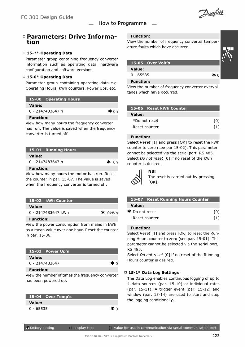
Parameters: Drive Informa-tion
15-** Operating Data
Parameter group containing frequency converterinformation such as operating data, hardwareconfiguration and software versions.
15-0* Operating Data
Parameter group containing operating data e.g.Operating Hours, kWh counters, Power Ups, etc.
15-00 Operating Hours
Value:
0 - 2147483647 h 0h
Function:View how many hours the frequency converterhas run. The value is saved when the frequencyconverter is turned off.
15-01 Running Hours
Value:
0 - 2147483647 h 0h
Function:View how many hours the motor has run. Resetthe counter in par. 15-07. The value is savedwhen the frequency converter is turned off.
15-02 kWh Counter
Value:
0 - 2147483647 kWh 0kWh
Function:View the power consumption from mains in kWhas a mean value over one hour. Reset the counterin par. 15-06.
15-03 Power Up's
Value:
0 - 2147483647 0
Function:View the number of times the frequency converterhas been powered up.
15-04 Over Temp's
Value:
0 - 65535 0
Function:View the number of frequency converter temper-ature faults which have occurred.
15-05 Over Volt's
Value:
0 - 65535 0
Function:View the number of frequency converter overvol-tages which have occurred.
15-06 Reset kWh Counter
Value:
*Do not reset [0]
Reset counter [1]
Function:Select Reset [1] and press [OK] to reset the kWhcounter to zero (see par 15-02). This parametercannot be selected via the serial port, RS 485.Select Do not reset [0] if no reset of the kWhcounter is desired.
NB!The reset is carried out by pressing[OK].
15-07 Reset Running Hours Counter
Value:
Do not reset [0]
Reset counter [1]
Function:Select Reset [1] and press [OK] to reset the Run-ning Hours counter to zero (see par. 15-01). Thisparameter cannot be selected via the serial port,RS 485.Select Do not reset [0] if no reset of the RunningHours counter is desired.
15-1* Data Log Settings
The Data Log enables continuous logging of up to4 data sources (par. 15-10) at individual rates(par. 15-11). A trigger event (par. 15-12) andwindow (par. 15-14) are used to start and stopthe logging conditionally.
FC 300 Design Guide How to Programme
factory setting () display text [] value for use in communication via serial communication port
MG.33.B7.02 - VLT is a registered Danfoss trademark 223

15-10 Logging Source
Array [4]
Value:
None
16-00 Control Word
16-01 Reference [Unit]
16-02 Reference %
16-03 Status Word
16-10 Power [kW]
16-11 Power [hp]
16-12 Motor Voltage
16-13 Frequency
16-14 Motor Current
16-16 Torque
16-17 Speed [RPM]
16-18 Motor Thermal
16-30 DC Link Voltage
16-32 Brake Energy / s
16-33 Brake Energy / 2 min
16-34 Heatsink Temp.
16-35 Inverter Thermal
16-50 External Reference
16-51 Pulse Reference
16-52 Feedback [Unit]
16-54 Feedback 1 [Unit]
16-55 Feedback 2 [Unit]
16-56 Feedback 3 [Unit]
16-60 Digital Input
16-62 Analog Input 53
16-64 Analog Input 54
16-65 Analog Output 42 [mA]
16-66 Digital Output [bin]
16-75 Analog In X30/11
16-76 Analog In X30/12
16-77 Analog Out X30/8 [mA]
16-90 Alarm Word
16-92 Warning Word
16-94 Extended Status Word
34-70 MCO Alarm Word 1
34-71 MCO Alarm Word 2
Function:Select which variables are to be logged.
15-11 Logging Interval
Value:
1 - 86400000 ms 1ms
Function:Enter the interval in milliseconds between eachsampling of the variables to be logged.
15-12 Trigger Event
Value:
*False [0]
True [1]
Running [2]
In range [3]
On reference [4]
Torque limit [5]
Current limit [6]
Out of current range [7]
Below I low [8]
Above I high [9]
Out of speed range [10]
Below speed low [11]
Above speed high [12]
Out of feedb. range [13]
Below feedb. low [14]
Above feedb. high [15]
Thermal warning [16]
Mains voltage out of range [17]
Reversing [18]
Warning [19]
Alarm (trip) [20]
Alarm (trip lock) [21]
Comparator 0 [22]
Comparator 1 [23]
Comparator 2 [24]
Comparator 3 [25]
Logic rule 0 [26]
Logic rule 1 [27]
Logic rule 2 [28]
Logic rule 3 [29]
Digital input DI18 [33]
Digital input DI19 [34]
Digital input DI27 [35]
Digital input DI29 (FC 302 only) [36]
Digital input DI32 [37]
FC 300 Design Guide How to Programme
factory setting () display text [] value for use in communication via serial communication port
224 MG.33.B7.02 - VLT is a registered Danfoss trademark
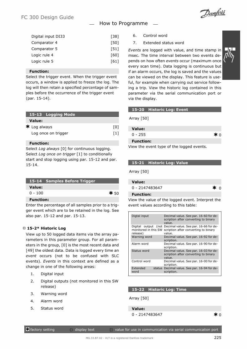
Digital input DI33 [38]
Comparator 4 [50]
Comparator 5 [51]
Logic rule 4 [60]
Logic rule 5 [61]
Function:Select the trigger event. When the trigger eventoccurs, a window is applied to freeze the log. Thelog will then retain a specified percentage of sam-ples before the occurrence of the trigger event(par. 15-14).
15-13 Logging Mode
Value:
Log always [0]
Log once on trigger [1]
Function:Select Log always [0] for continuous logging.Select Log once on trigger [1] to conditionallystart and stop logging using par. 15-12 and par.15-14.
15-14 Samples Before Trigger
Value:
0 - 100 50
Function:Enter the percentage of all samples prior to a trig-ger event which are to be retained in the log. Seealso par. 15-12 and par. 15-13.
15-2* Historic Log
View up to 50 logged data items via the array pa-rameters in this parameter group. For all param-eters in the group, [0] is the most recent data and[49] the oldest data. Data is logged every time anevent occurs (not to be confused with SLCevents). Events in this context are defined as achange in one of the following areas:
1. Digital input
2. Digital outputs (not monitored in this SWrelease)
3. Warning word
4. Alarm word
5. Status word
6. Control word
7. Extended status word
Events are logged with value, and time stamp inmsec. The time interval between two events de-pends on how often events occur (maximum onceevery scan time). Data logging is continuous butif an alarm occurs, the log is saved and the valuescan be viewed on the display. This feature is use-ful, for example when carrying out service follow-ing a trip. View the historic log contained in thisparameter via the serial communication port orvia the display.
15-20 Historic Log: Event
Array [50]
Value:
0 - 255 0
Function:View the event type of the logged events.
15-21 Historic Log: Value
Array [50]
Value:
0 - 2147483647 0
Function:View the value of the logged event. Interpret theevent values according to this table:
Digtal input Decimal value. See par. 16-60 for de-scription after converting to binaryvalue.
Digital output (notmonitored in this SWrelease)
Decimal value. See par. 16-66 for de-scription after converting to binaryvalue.
Warning word Decimal value. See par. 16-92 for de-scription.
Alarm word Decimal value. See par. 16-90 for de-scription.
Status word Decimal value. See par. 16-03 for de-scription after converting to binaryvalue.
Control word Decimal value. See par. 16-00 for de-scription.
Extended statusword
Decimal value. See par. 16-94 for de-scription.
15-22 Historic Log: Time
Array [50]
Value:
0 - 2147483647 0
FC 300 Design Guide How to Programme
factory setting () display text [] value for use in communication via serial communication port
MG.33.B7.02 - VLT is a registered Danfoss trademark 225

Function:View the time at which the logged event occurred.Time is measured in ms since frequency converterstart.
15-3* Fault Log
Parameters in this group are array parameters,where up to 10 fault logs can be viewed. [0] is themost recent logged data, and [9] the oldest. Errorcodes, values, and time stamp can be viewed forall logged data.
15-30 Fault Log: Error Code
Array [10]
Value:
0 - 255 0
Function:View the error code and look up its meaning in theTroubleshooting chapter of the FC 300 DesignGuide.
15-31 Fault Log: Value
Array [10]
Value:
-32767 - 32767 0
Function:View an extra description of the error. This pa-rameter is mostly used in combination with alarm38 internal fault.
15-32 Fault Log: Time
Array [10]
Value:
0 - 2147483647 0
Function:View the time when the logged event occurred.Time is measured in seconds from frequency con-verter start-up.
15-4* Drive Identification
Parameters containing read only informationabout the hardware and software configuration ofthe frequency converter.
15-40 FC Type
Function:View the FC type. The read-out is identical to theFC 300 Series power field of the type code defini-tion, characters 1-6.
15-41 Power Section
Function:View the FC type. The read-out is identical to theFC 300 Series power field of the type code defini-tion, characters 7-10.
15-42 Voltage
Function:View the FC type. The read-out is identical to theFC 300 Series power field of the type code defini-tion, characters 11-12.
15-43 Software Version
Function:View the combined SW version (or package ver-sion) consisting of power SW and control SW.
15-44 Ordered Typecode String
Function:View the type code string used for re-ordering thefrequency converter in its original configuration.
15-45 Actual Typecode String
Function:View the actual type code string.
15-46 Frequency Converter Ordering No
Function:View the 8-digit ordering number used for re-or-dering the frequency converter in its original con-figuration.
15-47 Power Card Ordering No
Function:View the power card ordering number.
FC 300 Design Guide How to Programme
factory setting () display text [] value for use in communication via serial communication port
226 MG.33.B7.02 - VLT is a registered Danfoss trademark

15-48 LCP Id No
Function:View the LCP ID number.
15-49 SW ID Control Card
Function:View the control card software version number.
15-50 SW ID Power Card
Function:View the power card software version number.
15-51Frequency Converter Serial Num-ber
Function:View the frequency converter serial number.
15-53 Power Card Serial Number
Function:View the power card serial number.
15-6* Option Ident.
This read-only parameter group contains informa-tion about the hardware and software configura-tion of the options installed in slots A, B C0 andC1.
15-60 Option Mounted
Function:View the installed option type.
15-61 Option SW Version
Function:View the installed option software version.
15-62 Option Ordering No
Function:Shows the ordering number for the installed op-tions.
15-63 Option Serial No
Function:View the installed option serial number.
15-70 Option in Slot A
Function:View the type code string for the option installedin slot A, and a translation of the type code string.E.g. for type code string AX the translation is Nooption.
15-71 Slot A Option SW Version
Function:View the software version for the option installedin slot A.
15-72 Option in Slot B
Function:View the type code string for the option installedin slot B, and a translation of the type code string.E.g. for type code string BX the translation is Nooption.
15-73 Slot B Option SW Version
Function:View the software version for the option installedin slot B.
15-74 Option in Slot C
Function:View the type code string for the option installedin slot C, and a translation of the type code string.E.g. for type code string CXXXX the translation isNo option.
15-75 Slot C Option SW Version
Function:View the software version for the option installedin slot C.
FC 300 Design Guide How to Programme
factory setting () display text [] value for use in communication via serial communication port
MG.33.B7.02 - VLT is a registered Danfoss trademark 227
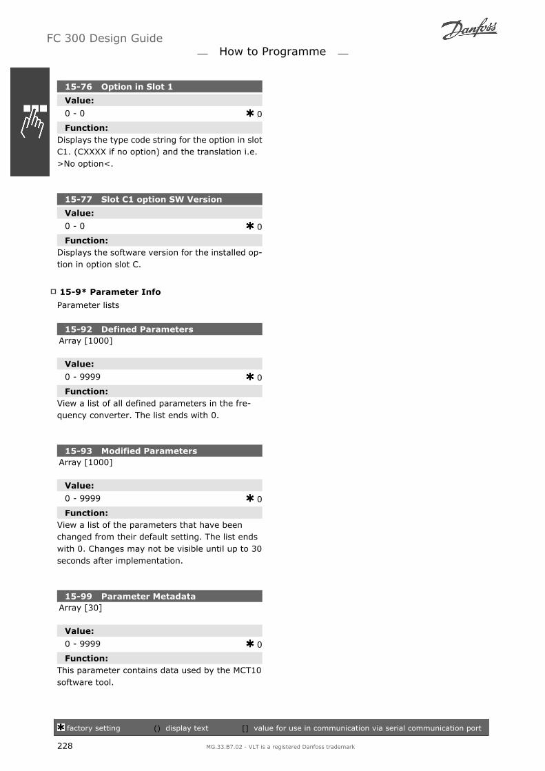
15-76 Option in Slot 1
Value:
0 - 0 0
Function:Displays the type code string for the option in slotC1. (CXXXX if no option) and the translation i.e.>No option<.
15-77 Slot C1 option SW Version
Value:
0 - 0 0
Function:Displays the software version for the installed op-tion in option slot C.
15-9* Parameter Info
Parameter lists
15-92 Defined ParametersArray [1000]
Value:
0 - 9999 0
Function:View a list of all defined parameters in the fre-quency converter. The list ends with 0.
15-93 Modified ParametersArray [1000]
Value:
0 - 9999 0
Function:View a list of the parameters that have beenchanged from their default setting. The list endswith 0. Changes may not be visible until up to 30seconds after implementation.
15-99 Parameter MetadataArray [30]
Value:
0 - 9999 0
Function:This parameter contains data used by the MCT10software tool.
FC 300 Design Guide How to Programme
factory setting () display text [] value for use in communication via serial communication port
228 MG.33.B7.02 - VLT is a registered Danfoss trademark

Parameters: Data Read-outs
16-** Data Read-outs
Parameter group for data read-outs, e.g. actualreferences, voltages, control, alarm, warning andstatus words.
16-0* General Status
Parameters for reading the general status, e.g.the calculated reference, the active control word,status.
16-00 Control Word
Value:
0 - FFFF 0
Function:View the Control word sent from the frequencyconverter via the serial communication port in hexcode.
16-01 Reference [Unit]
Value:
-999999.000 - 999999.000 0.000
Function:View the present reference value applied on im-pulse or analog basis in the unit resulting from theconfiguration selected in par. 1-00 (Hz, Nm orRPM).
16-02 Reference %
Value:
-200.0 - 200.0 % 0.0%
Function:View the total reference. The total reference is thesum of digital, analog, preset, bus, and freeze ref-erences, plus catch-up and slow-down.
16-03 Status Word
Value:
0 - FFFF 0
Function:View the Status word sent from the frequencyconverter via the serial communication port in hexcode.
16-05 Main Actual Value [%]
Value:
0 - 0 N/A N/A
Function:View the two-byte word sent with the Status wordto the bus Master reporting the Main Actual Value.Please refer to the VLT® AutomationDrive FC 300Profibus Operating Instructions MG.33.CX.YY for adetailed description.
16-1* Motor Status
Parameters for reading the motor status values.
16-10 Power [kW]
Value:
0.0 - 1000.0 kW 0.0kW
Function:View the motor power in kW. The value shown iscalculated on the basis of the actual motor voltageand motor current. The value is filtered, andtherefore approx. 1.3 seconds may pass fromwhen an input value changes to when the dataread-out values change.
16-11 Power [hp]
Value:
0.00 - 1000.00 hp 0.00hp
Function:View the motor power in hp. The value shown iscalculated on the basis of the actual motor voltageand motor current. The value is filtered, andtherefore approx. 1.3 seconds may pass fromwhen an input value changes to when the dataread-out values change.
16-12 Motor Voltage
Value:
0.0 - 6000.0 V 0.0V
Function:View the motor voltage, a calculated value usedfor controlling the motor.
FC 300 Design Guide How to Programme
factory setting () display text [] value for use in communication via serial communication port
MG.33.B7.02 - VLT is a registered Danfoss trademark 229

16-13 Frequency
Value:
0.0 - 6500.0 Hz 0.0Hz
Function:View the motor frequency, without resonancedampening.
16-14 Motor Current
Value:
0.00 - 0.00 A 0.00A
Function:View the motor current measured as a mean val-ue, IRMS. The value is filtered, and thus approx.1.3 seconds may pass from when an input valuechanges to when the data read-out valueschange.
16-15 Frequency [%]
Value:
0.00 - 0.00 % 0.00%
Function:View a two-byte word reporting the actual motorfrequency (without resonance dampening) as apercentage (scale 0000-4000 Hex) of par. 4-19Max. Output Frequency. Set par. 9-16 index 1 tosend it with the Status Word instead of the MAV.
16-16 Torque
Value:
-3000.0 - 3000.0 Nm 0.0Nm
Function:View the torque value with sign, applied to themotor shaft. Linearity is not exact between 160%motor current and torque in relation to the ratedtorque. Some motors supply more than 160% tor-que. Consequently, the min. value and the max.value will depend on the max. motor current aswell as the motor used. The value is filtered, andthus approx. 1.3 seconds may pass from when aninput changes value to when the data read-outvalues change.
16-17 Speed [RPM]
Value:
0 - 0 RPM 0 RPM
Function:View the actual motor RPM. In open loop or closedloop process control the motor RPM is estimated.In speed closed loop modes the motor RPM ismeasured.
16-18 Motor Thermal
Value:
0 - 100 % 0 %
Function:View the calculated thermal load on the motor.The cut-out limit is 100%. The basis for calcula-tion is the ETR function selected in par.1-90.
16-19 KTY Sensor Temperature
Value:
0 - xxx °C 0°C
Function:Returning the actual temperature on KTY sensorbuild in the motor.See par. 1-9*.
16-20 Motor Angle
Value:
0 - 65535 0
Function:View the current encoder/resolver angle offsetrelative to the index position. The value range of0-65535 corresponds to 0-2*pi (radians).
16-22 Torque [%]
Value:
-200 - 200% 0%
Function:Value shown is the torque in percent of nominaltorque, with sign, applied to the motor shaft.
FC 300 Design Guide How to Programme
factory setting () display text [] value for use in communication via serial communication port
230 MG.33.B7.02 - VLT is a registered Danfoss trademark

16-3* Drive Status
Parameters for reporting the status of the fre-quency converter.
16-30 DC Link Voltage
Value:
0 - 10000 V 0V
Function:View a measured value. The value is filtered, andthus approx. 1.3 seconds may pass from when aninput value changes to when the data read-outvalue changes.
16-32 Brake Energy /s
Value:
0.000 - 0.000 kW 0.000kW
Function:View the brake power transmitted to an externalbrake resistor, stated as an instantaneous value.
16-33 Brake Energy /2 min
Value:
0.000 - 500.000 kW 0.000kW
Function:View the brake power transmitted to an externalbrake resistor. The mean power is calculated onan average basis for the most recent 120 seconds.
16-34 Heatsink Temp.
Value:
0 - 255 °C 0°C
Function:View the frequency converter heatsink tempera-ture. The cut-out limit is 90 ± 5 °C, and the motorcuts back in at 60 ± 5 °C.
16-35 Inverter Thermal
Value:
0 - 0 % 0 %
Function:View the percentage load on the inverter.
16-36 Inv. Nom. Current
Value:
0.01 - 10000.00 A A
Function:View the inverter nominal current, which shouldmatch the nameplate data on the connected mo-tor. The data are used for calculation of torque,motor protection, etc.
16-37 Inv. Max. Current
Value:
0.01 - 10000.00 A A
Function:View the inverter maximum current, which shouldmatch the nameplate data on the connected mo-tor. The data are used for calculation of torque,motor protection, etc.
16-38 SL Controller State
Value:
0 - 100 0
Function:View the state of the event under execution by theSL controller.
16-39 Control Card Temp.
Value:
0 - 100 °C 0°C
Function:View the temperature on the control card, statedin °C.
16-40 Logging Buffer Full
Value:
No [0]
Yes [1]
Function:View whether the logging buffer is full (see par.15-1*). The logging buffer will never be full whenpar. 15-13 Logging Mode is set to Log always [0].
16-5* Ref. & Feedb.
Parameters for reporting the reference and feed-back input.
FC 300 Design Guide How to Programme
factory setting () display text [] value for use in communication via serial communication port
MG.33.B7.02 - VLT is a registered Danfoss trademark 231

16-50 External Reference
Value:
-200.0 - 200.0 0.0
Function:View the total reference, the sum of digital, ana-log, preset, bus and freeze references, plus catch-up and slow-down.
16-51 Pulse Reference
Value:
-200 - 200 0.0
Function:View the reference value from programmed digitalinput(s). The read-out can also reflect the impul-ses from an incremental encoder .
16-52 Feedback [Unit]
Value:
-999999.999 - 999999.999 0.0
Function:View the feedback unit resulting from the selec-tion of unit and scaling in par. 3-00, 3-01, 3-02and 3-03.
16-53 Digi Pot Reference
Value:
-200 - 200 0.0
Function:View the contribution of the Digital Potentiometerto the actual reference.
16-6* Inputs and Outputs
Parameters for reporting the digital and analog IOports.
16-60 Digital Input
Value:
0 - 63 0
Function:View the signal states from the active digital in-puts. Input 18 corresponds to the bit at the farleft. 0 = no signal, 1 = connected signal.
Bit 0 Digital input term. 33Bit 1 Digital input term. 32Bit 2 Digital input term. 29Bit 3 Digital input term. 27Bit 4 Digital input term. 19Bit 5 Digital input term. 18Bit 6 Digital input term. 37Bit 7 Digital input GP I/O term. X30/2Bit 8 Digital input GP I/O term. X30/3Bit 9 Digital input GP I/O term. X30/4Bit 10-63 Reserved for future terminals
16-61 Terminal 53 Switch Setting
Value:
Current [0]
Voltage [1]
Function:View the setting of input terminal 53. Current =0; Voltage = 1.
16-62 Analog Input 53
Value:
-20.000 - 20.000 0.000
Function:View the actual value at input 53.
16-63 Terminal 54 Switch Setting
Value:
Current [0]
Voltage [1]
Function:View the setting of input terminal 54. Current =0; Voltage = 1.
16-64 Analog Input 54
Value:
-20.000 - 20.000 0.000
Function:View the actual value at input 54.
FC 300 Design Guide How to Programme
factory setting () display text [] value for use in communication via serial communication port
232 MG.33.B7.02 - VLT is a registered Danfoss trademark

16-65 Analog Output 42 [mA]
Value:
0.000 - 30.000 0.000
Function:View the actual value at output 42 in mA. The val-ue shown reflects the selection in par. 06-50.
16-66 Digital Output [bin]
Value:
0 - 115 0
Function:View the binary value of all digital outputs.
16-67 Freq. Input #29 [Hz]
Value:
0 - 0 0
Function:View the actual frequency rate on terminal 29.This parameter is available for FC 302 only.
16-68 Freq. Input #33 [Hz]
Value:
0 - 130000 0
Function:View the actual value of the frequency applied atterminal 33 as an impulse input.
16-69 Pulse Output #27 [Hz]
Value:
0 - 40000 0
Function:View the actual value of impulses applied to ter-minal 27 in digital output mode.
16-70 Pulse Output #29 [Hz]
Value:
0 - 40000 0
Function:View the actual value of pulses to terminal 29 indigital output mode.This parameter is available for FC 302 only.
16-71 Relay Output [bin]
Value:
0 - 31 0
Function:View the settings of all relays.
16-72 Counter A
Value:
-2147483648 -2147483647 0
Function:View the present value of Counter A. Counters areuseful as comparator operands, see par. 13-10.The value can be reset or changed either via dig-ital inputs (parameter group 5-1*) or by using anSLC action (par. 13-52).
16-73 Counter B
Value:
-2147483648 -2147483647 0
Function:View the present value of Counter B. Counters areuseful as comparator operands (par. 13-10).The value can be reset or changed either via dig-ital inputs (parameter group 5-1*) or by using anSLC action (par. 13-52).
16-74 Precise Stop Counter
Value:
0 - 2147483647 0
Function:Returns the actual counter value of precise coun-ter (par. 1-84).
16-75 Analog In X30/11
Value:
0.000 - 0.000 0.000
Function:View the actual value at input X30/11 of MCB 101.
FC 300 Design Guide How to Programme
factory setting () display text [] value for use in communication via serial communication port
MG.33.B7.02 - VLT is a registered Danfoss trademark 233

16-76 Analog In X30/12
Value:
0.000 - 0.000 0.000
Function:View the actual value at input X30/12 of MCB 101.
16-77 Analog Out X30/8 16-77 [mA]
Value:
0.000 - 0.000 0.000
Function:View the actual value at input X30/8 in mA.
16-8* Fieldbus & FC Port
Parameters for reporting the BUS references andcontrol words.
16-80 Fieldbus CTW 1
Value:
0 - 65535 0
Function:View the two-byte Control word (CTW) receivedfrom the Bus-Master. Interpretation of the Controlword depends on the fieldbus option installed andthe Control word profile selected in par. 8-10.For more information please refer to the relevantfieldbus manual.
16-82 Fieldbus REF 1
Function:View the two-byte word sent with the control wordform the Bus-Master to set the reference value.For more information please refer to the relevantfieldbus manual.
16-84 Comm. Option STW
Value:
0 - 65535 0
Function:View the extended fieldbus comm. option statusword.For more information please refer to the relevantfieldbus manual.
16-85 FC Port CTW 1
Value:
0 - 65535 0
Function:View the two-byte Control word (CTW) receivedfrom the Bus-Master. Interpretation of the controlword depends on the fieldbus option installed andthe Control word profile selected in par. 8-10.
16-86 FC Port REF 1
Value:
0 - 0 0
Function:View the two-byte Status word (STW) sent to theBus-Master. Interpretation of the Status word de-pends on the fieldbus option installed and theControl word profile selected in par. 8-10.
16-9* Diagnosis Read-Out
Parameters displaying alarm, warning and exten-ded status words.
16-90 Alarm Word
Value:
0 - FFFF 0
Function:View the alarm word sent via the serial commu-nication port in hex code.
16-92 Warning Word
Value:
0 - FFFF 0
Function:View the warning word sent via the serial com-munication port in hex code.
16-93 Warning Word 2
Value:
0 - FFFF 0
Function:View the warning word sent via the serial com-munication port in hex code.
FC 300 Design Guide How to Programme
factory setting () display text [] value for use in communication via serial communication port
234 MG.33.B7.02 - VLT is a registered Danfoss trademark

16-94 Ext. Status Word
Value:
0 - FFFF 0
Function:Returns the extended warning word sent via theserial communication port in hex code.
FC 300 Design Guide How to Programme
MG.33.B7.02 - VLT is a registered Danfoss trademark 235

Parameters: EncoderInput
17-** Motor Feedb. Option
Additional parameters to configure the Encoder(MCB102) or the Resolver (MCB103) FeedbackOption.
17-1* Inc. Enc. Interface
Parameters in this group configure the incremen-tal interface of the MCB102 option. Note that boththe incremental and absolute interfaces are activeat the same time.
17-10 Signal Type
Value:
None [0]
RS422 (5V TTL/linedrv.) [1]
Sinusoidal 1Vpp [2]
Function:Select the incremental type (A/B channel) of theencoder in use. Find the information on the en-coder data sheet.Select None [0] if the feedback sensor is an ab-solute encoder only.This parameter cannot be adjusted while the mo-tor is running.
17-11 Resolution (PPR)
Value:
10 - 10000 1024
Function:Enter the resolution of the incremental track, i.e.the number of pulses or periods per revolution.This parameter cannot be adjusted while the mo-tor is running.
17-2* Abs. Enc. Interface
Parameters in this group configure the absoluteinterface of the MCB102 option. Note that both theincremental and absolute interfaces are active atthe same time.
17-20 Protocol Selection
Value:
None [0]
HIPERFACE [1]
EnDat [2]
SSI [4]
Function:Select HIPERFACE [1] if the encoder is absoluteonly.Select None [0] if the feedback sensor is an in-cremental encoder only.This parameter cannot be adjusted while the mo-tor is running.
17-21 Resolution (Positions/Rev)
Value:
512 [512]
1024 [1024]
2048 [2048]
4096 [4096]
SSI 4 - 8192 [8192]
16384 [16384]
HIPERFACE 512 - 32768 [32768]
Function:Select the resolution of the absolute encoder, i.e.the number of counts per revolution.This parameter cannot be adjusted while the mo-tor is running.
17-24 SSI Data Length
Value:
13 - 25 13
Function:Set the number of bits for the SSI telegram.Choose 13 bits for single-turn encoders and 25bits for multi-turn encoder.
17-25 Clock Rate
Value:
100 - 260 kHz 260kHz
Function:Set the SSI clock rate. By long encoder cables theclock rate must be reduced.
17-26 SSI Data Format
Value:
Gray Code [0]
Binary Code [1]
FC 300 Design Guide How to Programme
factory setting () display text [] value for use in communication via serial communication port
236 MG.33.B7.02 - VLT is a registered Danfoss trademark

Function:Set the data format of the SSI data. Choose be-tween Gray or Binary format.
17-34 HIPERFACE Baudrate
Value:
600 [0]
1200 [1]
2400 [2]
4800 [3]
9600 [4]
19200 [5]
38400 [6]
Function:Select the baud rate of the attached encoder.This parameter cannot be adjusted while the mo-tor is running.
17-5* Resolver Interface
Parameter group 17-5* is used for setting param-eters for the MCB 103 Resolver Option.Usually the resolver feedback is used as motorfeedback from Permanent Magnet motors withpar. 1-01 set to Flux with motor feedback.Resolver parameters cannot be adjusted while themotor is running.
17-50 Resolver Poles
Value:
2-2 2
Function:Set the number of poles on the resolver. Most re-solvers have 2 poles.The value is stated in the data sheet for resolvers.
17-51 Resolver Input Voltage
Value:
4.0 - 8.0 V 7.0V
Function:Set the input voltage to the resolver. The voltageis stated as RMS value.The value is stated in the data sheet for resolvers
17-52 Resolver Input Frequency
Value:
2.0 - 15.0 kHz 10.0kHz
Function:Set the input frequency to the resolver.The value is stated in the data sheet for resolvers.
17-53 Resolver Transformation Ratio
Value:
0.1 - 1.1 0.5
Function:Set the transformation ratio for the resolver.The transformation ration is:
Tratio =VOutVIn
The value is stated in the data sheet for resolvers.
17-59 Resolver Interface
Value:
Disabled [0]
Enabled [1]
Function:Activate the MCB 103 resolver option when theresolver parameters are selected.To avoid damage of resolvers par. 17-50 par.17-53 must be adjusted before activating this pa-rameter.
17-6* Monitoring and Application
This parameter group is selecting additional func-tions when MCB 102 Encoder option or MCB 103Resolver option is fitted into option slot B as speedfeedback.Monitoring and Application parameters cannot beadjusted while the motor is running.
17-60 Encoder Positive Direction
Value:
* Clockwise [0]
Counter clockwise [1]
Function:Change the detected encoder rotation directionwithout changing the wiring to the encoder.This parameter cannot be adjusted while the mo-tor is running.
FC 300 Design Guide How to Programme
factory setting () display text [] value for use in communication via serial communication port
MG.33.B7.02 - VLT is a registered Danfoss trademark 237

17-61 Encoder Signal Monitoring
Value:
Disabled [0]
Warning [1]
Trip [2]
Function:Select which reaction the frequency convertershould take in case a fault encoder signal is de-tected.The encoder function in par. 17-61 is an electricalcheck of the hardware circuit in the encoder SYS-TEM.
FC 300 Design Guide How to Programme
238 MG.33.B7.02 - VLT is a registered Danfoss trademark
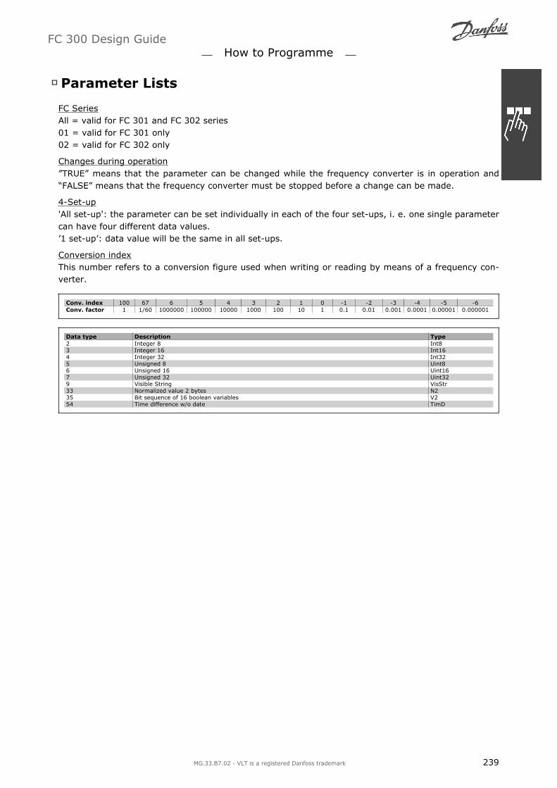
Parameter Lists
FC SeriesAll = valid for FC 301 and FC 302 series01 = valid for FC 301 only02 = valid for FC 302 only
Changes during operationTRUE means that the parameter can be changed while the frequency converter is in operation andFALSE means that the frequency converter must be stopped before a change can be made.
4-Set-up'All set-up': the parameter can be set individually in each of the four set-ups, i. e. one single parametercan have four different data values.1 set-up: data value will be the same in all set-ups.
Conversion indexThis number refers to a conversion figure used when writing or reading by means of a frequency con-verter.
Conv. index 100 67 6 5 4 3 2 1 0 -1 -2 -3 -4 -5 -6Conv. factor 1 1/60 1000000 100000 10000 1000 100 10 1 0.1 0.01 0.001 0.0001 0.00001 0.000001
Data type Description Type2 Integer 8 Int83 Integer 16 Int164 Integer 32 Int325 Unsigned 8 Uint86 Unsigned 16 Uint167 Unsigned 32 Uint329 Visible String VisStr33 Normalized value 2 bytes N235 Bit sequence of 16 boolean variables V254 Time difference w/o date TimD
FC 300 Design Guide How to Programme
MG.33.B7.02 - VLT is a registered Danfoss trademark 239

0-** Operation/Display
Par.No.#
Parameter description Default value 4-set-up FC 302only
Changeduringopera-tion
Conver-sion in-
dex
Type
0-0* Basic Settings0-01 Language [0] English 1 set-up TRUE - Uint80-02 Motor Speed Unit [0] RPM 2 set-ups FALSE - Uint80-03 Regional Settings [0] International 2 set-ups FALSE - Uint8
0-04Operating State at Power-up(Hand)
[1] Forced stop,ref=old All set-ups TRUE - Uint8
0-1* Set-up Operations0-10 Active Set-up [1] Set-up 1 1 set-up TRUE - Uint80-11 Edit Set-up [1] Set-up 1 All set-ups TRUE - Uint80-12 This Set-up Linked to [0] Not linked All set-ups FALSE - Uint8
0-13 Readout: Linked Set-ups 0 All set-ups FALSE 0Uint1
60-14 Readout: Edit Set-ups / Channel 0 All set-ups TRUE 0 Int320-2* LCP Display
0-20 Display Line 1.1 Small Speed [RPM] All set-ups TRUE -Uint1
6
0-21 Display Line 1.2 Small Motor current [A] All set-ups TRUE -Uint1
6
0-22 Display Line 1.3 Small Power [kW] All set-ups TRUE -Uint1
6
0-23 Display Line 2 Large Frequency [Hz] All set-ups TRUE -Uint1
6
0-24 Display Line 3 Large Reference [%] All set-ups TRUE -Uint1
6
0-25 My Personal Menu - 1 set-up TRUE 0Uint1
60-3* LCP Custom Readout0-30 Unit for User-defined Readout [0] None All set-ups TRUE - Uint80-31 Min Value of User-defined Read-
out 0.00 All set-ups TRUE -2 Int320-32 Max Value of User-defined Read-
out 100.00 All set-ups TRUE -2 Int320-4* LCP Keypad0-40 [Hand on] Key on LCP [1] Enabled All set-ups TRUE - Uint80-41 [Off] Key on LCP [1] Enabled All set-ups TRUE - Uint80-42 [Auto on] Key on LCP [1] Enabled All set-ups TRUE - Uint80-43 [Reset] Key on LCP [1] Enabled All set-ups TRUE - Uint80-5* Copy/Save0-50 LCP Copy [0] No copy All set-ups FALSE - Uint80-51 Set-up Copy [0] No copy All set-ups FALSE - Uint80-6* Password
0-60 Main Menu Password 100 1 set-up TRUE 0Uint1
6
0-61Access to Main Menu w/o Pass-word [0] Full access 1 set-up TRUE - Uint8
0-65 Quick Menu Password 200 1 set-up TRUE 0Uint1
6
0-66Access to Quick Menu w/o Pass-word [0] Full access 1 set-up TRUE - Uint8
FC 300 Design Guide How to Programme
240 MG.33.B7.02 - VLT is a registered Danfoss trademark

1-** Load/Motor
Par.No. #
Parameter description Default value(SR - Size Rela-ted)
4-set-up FC 302only
Changeduring op-
eration
Conver-sion in-
dex
Type
1-0* General Settings1-00 Configuration Mode - All set-ups TRUE - Uint81-01 Motor Control Principle - All set-ups FALSE - Uint81-02 Flux Motor Feedback Source [1] 24V encoder All set-ups x FALSE - Uint8
1-03 Torque Characteristics[0] Constanttorque All set-ups TRUE - Uint8
1-04 Overload Mode [0] High torque All set-ups FALSE - Uint8
1-05 Local Mode Configuration[2] Mode as par1-00 All set-ups TRUE - Uint8
1-1* Motor Selection1-10 Motor Construction [0] Asynchron All set-ups FALSE - Uint81-2* Motor Data1-20 Motor Power [kW] SR All set-ups FALSE 1 Uint321-21 Motor Power [HP] SR All set-ups FALSE -2 Uint321-22 Motor Voltage SR All set-ups FALSE 0 Uint161-23 Motor Frequency SR All set-ups FALSE 0 Uint161-24 Motor Current SR All set-ups FALSE -2 Uint321-25 Motor Nominal Speed SR All set-ups FALSE 67 Uint161-26 Motor Cont. Rated Torque SR All set-ups FALSE -1 Uint32
1-29Automatic Motor Adaptation(AMA) [0] Off All set-ups FALSE - Uint8
1-3* Adv. Motor Data1-30 Stator Resistance (Rs) SR All set-ups FALSE -4 Uint321-31 Rotor Resistance (Rr) SR All set-ups FALSE -4 Uint321-33 Stator Leakage Reactance (X1) SR All set-ups FALSE -4 Uint321-34 Rotor Leakage Reactance (X2) SR All set-ups FALSE -4 Uint321-35 Main Reactance (Xh) SR All set-ups FALSE -4 Uint321-36 Iron Loss Resistance (Rfe) SR All set-ups FALSE -3 Uint321-37 d-axis Inductance (Ld) SR All set-ups x FALSE -4 Int321-39 Motor Poles SR All set-ups FALSE 0 Uint81-40 Back EMF at 1000 RPM SR All set-ups x FALSE 0 Uint161-41 Motor Angle Offset 0 All set-ups FALSE 0 Int161-5* Load Indep. Setting
1-50Motor Magnetisation at ZeroSpeed 100 % All set-ups TRUE 0 Uint16
1-51Min Speed Normal Magnetising[RPM] SR All set-ups TRUE 67 Uint16
1-52Min Speed Normal Magnetising[Hz] SR All set-ups TRUE -1 Uint16
1-53 Model Shift Frequency SR All set-ups x FALSE -1 Uint161-55 U/f Characteristic - U SR All set-ups TRUE -1 Uint161-56 U/f Characteristic - F SR All set-ups TRUE -1 Uint16
FC 300 Design Guide How to Programme
MG.33.B7.02 - VLT is a registered Danfoss trademark 241

Par.No.#
Parameter description Default value(SR = Size Rela-ted)
4-set-up FC 302only
Changeduring op-
eration
Conver-sion in-
dex
Type
1-6* Load Depen. Setting1-60 Low Speed Load Compensation 100 % All set-ups TRUE 0 Int161-61 High Speed Load Compensation 100 % All set-ups TRUE 0 Int161-62 Slip Compensation SR All set-ups TRUE 0 Int16
1-63Slip Compensation Time Con-stant 0.10 s All set-ups TRUE -2 Uint16
1-64 Resonance Dampening 100 % All set-ups TRUE 0 Uint16
1-65Resonance Dampening TimeConstant 5 ms All set-ups TRUE -3 Uint8
1-66 Min. Current at Low Speed 100 % All set-ups x TRUE 0 Uint81-67 Load Type [0] Passive load All set-ups x TRUE - Uint81-68 Minimum Inertia SR All set-ups x FALSE -4 Uint321-69 Maximum Inertia SR All set-ups x FALSE -4 Uint321-7* Start Adjustments1-71 Start Delay 0.0 s All set-ups TRUE -1 Uint8
1-72 Start Function[2] Coast/delaytime All set-ups TRUE - Uint8
1-73 Flying Start [RPM] [0] Disabled All set-ups FALSE - Uint81-74 Start Speed [RPM] SR All set-ups TRUE 67 Uint161-75 Start Speed [Hz] SR All set-ups TRUE -1 Uint161-76 Start Current 0.00 A All set-ups TRUE -2 Uint321-8* Stop Adjustments1-80 Function at Stop [0] Coast All set-ups TRUE - Uint8
1-81Min Speed for Function at Stop[RPM] SR All set-ups TRUE 67 Uint16
1-82Min Speed for Function at Stop[Hz] SR All set-ups TRUE -1 Uint16
1-83 Precise Stop Function[0] Precise rampstop All set-ups FALSE - Uint8
1-84 Precise Stop Counter Value 100000 All set-ups TRUE 0 Uint32
1-85Precise Stop Speed Compensa-tion Delay 10 ms All set-ups TRUE -3 Uint8
1-9* Motor Temperature
1-90 Motor Thermal Protection[0] No protec-tion All set-ups TRUE - Uint8
1-91 Motor External Fan [0] No All set-ups TRUE - Uint161-93 Thermistor Source [0] None All set-ups TRUE - Uint81-95 KTY Sensor Type [0] KTY Sensor 1 All set-ups x TRUE - Uint81-96 KTY Thermistor Source [0] None All set-ups x TRUE - Uint81-97 KTY Threshold level 80 °C 1 set-up x TRUE 100 Int16
FC 300 Design Guide How to Programme
242 MG.33.B7.02 - VLT is a registered Danfoss trademark
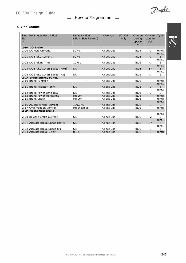
2-** Brakes
Par.No.#
Parameter description Default value(SR = Size Related)
4-set-up FC 302only
Changeduringopera-tion
Conver-sion in-
dex
Type
2-0* DC-Brake2-00 DC Hold Current 50 % All set-ups TRUE 0 Uint8
2-01 DC Brake Current 50 % All set-ups TRUE 0Uint1
6
2-02 DC Braking Time 10.0 s All set-ups TRUE -1Uint1
6
2-03 DC Brake Cut In Speed [RPM] SR All set-ups TRUE 67Uint1
6
2-04 DC Brake Cut In Speed [Hz] SR All set-ups TRUE -1Uint1
62-1* Brake Energy Funct.2-10 Brake Function - All set-ups TRUE - Uint8
2-11 Brake Resistor (ohm) SR All set-ups TRUE 0Uint1
6
2-12 Brake Power Limit (kW) SR All set-ups TRUE 0Uint3
22-13 Brake Power Monitoring [0] Off All set-ups TRUE - Uint82-15 Brake Check [0] Off All set-ups TRUE - Uint8
2-16 AC brake Max. Current 100.0 % All set-ups TRUE -1Uint3
22-17 Over-voltage Control [0] Disabled All set-ups TRUE - Uint82-2* Mechanical Brake
2-20 Release Brake Current SR All set-ups TRUE -2Uint3
2
2-21 Activate Brake Speed [RPM] SR All set-ups TRUE 67Uint1
6
2-22 Activate Brake Speed [Hz] SR All set-ups TRUE -1Uint1
62-23 Activate Brake Delay 0.0 s All set-ups TRUE -1 Uint8
FC 300 Design Guide How to Programme
MG.33.B7.02 - VLT is a registered Danfoss trademark 243

3-** Reference / Ramps
Par.No.#
Parameter description Default value(SR = Size Related)
4-set-up FC 302only
Changeduringopera-tion
Conver-sion in-
dex
Type
3-0* Reference Limits3-00 Reference Range - All set-ups TRUE - Uint83-01 Reference/Feedback Unit - All set-ups TRUE - Uint83-02 Minimum Reference SR All set-ups TRUE -3 Int323-03 Maximum Reference SR All set-ups TRUE -3 Int323-04 Reference Function [0] Sum All set-ups TRUE - Uint83-1* References3-10 Preset Reference 0.00 % All set-ups TRUE -2 Int16
3-11 Jog Speed [Hz] SR All set-ups TRUE -1Uint1
63-12 Catch up/slow Down Value 0.00 % All set-ups TRUE -2 Int16
3-13 Reference Site[0] Linked to Hand /Auto All set-ups TRUE - Uint8
3-14 Preset Relative Reference 0.00 % All set-ups TRUE -2 Int323-15 Reference Source 1 - All set-ups TRUE - Uint83-16 Reference Source 2 - All set-ups TRUE - Uint83-17 Reference Source 3 - All set-ups TRUE - Uint83-18 Relative Scaling Reference Source [0] No function All set-ups TRUE - Uint8
3-19 Jog Speed [RPM] SR All set-ups TRUE 67Uint1
63-4* Ramp 13-40 Ramp 1 Type [0] Linear All set-ups TRUE - Uint8
3-41 Ramp 1 Ramp up Time SR All set-ups TRUE -2Uint3
2
3-42 Ramp 1 Ramp Down Time SR All set-ups TRUE -2Uint3
2
3-45Ramp 1 S-ramp Ratio at Accel.Start 50 % All set-ups TRUE 0 Uint8
3-46Ramp 1 S-ramp Ratio at Accel.End 50 % All set-ups TRUE 0 Uint8
3-47Ramp 1 S-ramp Ratio at Decel.Start 50 % All set-ups TRUE 0 Uint8
3-48Ramp 1 S-ramp Ratio at Decel.End 50 % All set-ups TRUE 0 Uint8
3-5* Ramp 23-50 Ramp 2 Type [0] Linear All set-ups TRUE - Uint8
3-51 Ramp 2 Ramp up Time SR All set-ups TRUE -2Uint3
2
3-52 Ramp 2 Ramp down Time SR All set-ups TRUE -2Uint3
2
3-55Ramp 2 S-ramp Ratio at Accel.Start 50 % All set-ups TRUE 0 Uint8
3-56Ramp 2 S-ramp Ratio at Accel.End 50 % All set-ups TRUE 0 Uint8
3-57Ramp 2 S-ramp Ratio at Decel.Start 50 % All set-ups TRUE 0 Uint8
3-58Ramp 2 S-ramp Ratio at Decel.End 50 % All set-ups TRUE 0 Uint8
3-6* Ramp 33-60 Ramp 3 Type [0] Linear All set-ups TRUE - Uint8
3-61 Ramp 3 Ramp up Time SR All set-ups TRUE -2Uint3
2
3-62 Ramp 3 Ramp down Time SR All set-ups TRUE -2Uint3
2
3-65Ramp 3 S-ramp Ratio at Accel.Start 50 % All set-ups TRUE 0 Uint8
3-66Ramp 3 S-ramp Ratio at Accel.End 50 % All set-ups TRUE 0 Uint8
3-67Ramp 3 S-ramp Ratio at Decel.Start 50 % All set-ups TRUE 0 Uint8
3-68Ramp 3 S-ramp Ratio at Decel.End 50 % All set-ups TRUE 0 Uint8
FC 300 Design Guide How to Programme
244 MG.33.B7.02 - VLT is a registered Danfoss trademark

Par.No.#
Parameter description Default value(SR = Size Related)
4-set-up FC 302only
Changeduringopera-tion
Conver-sion in-
dex
Type
3-7* Ramp 43-70 Ramp 4 Type [0] Linear All set-ups TRUE - Uint8
3-71 Ramp 4 Ramp up Time SR All set-ups TRUE -2Uint3
2
3-72 Ramp 4 Ramp Down Time SR All set-ups TRUE -2Uint3
2
3-75Ramp 4 S-ramp Ratio at Accel.Start 50 % All set-ups TRUE 0 Uint8
3-76Ramp 4 S-ramp Ratio at Accel.End 50 % All set-ups TRUE 0 Uint8
3-77Ramp 4 S-ramp Ratio at Decel.Start 50 % All set-ups TRUE 0 Uint8
3-78Ramp 4 S-ramp Ratio at Decel.End 50 % All set-ups TRUE 0 Uint8
3-8* Other Ramps
3-80 Jog Ramp Time SR All set-ups TRUE -2Uint3
2
3-81 Quick Stop Ramp Time SR 2 set-ups TRUE -2Uint3
23-9* Digital Pot.Meter
3-90 Step Size 0.10 % All set-ups TRUE -2Uint1
6
3-91 Ramp Time 1.00 s All set-ups TRUE -2Uint3
23-92 Power Restore [0] Off All set-ups TRUE - Uint83-93 Maximum Limit 100 % All set-ups TRUE 0 Int163-94 Minimum Limit -100 % All set-ups TRUE 0 Int163-95 Ramp Delay 1.000 N/A All set-ups TRUE -3 TimD
FC 300 Design Guide How to Programme
MG.33.B7.02 - VLT is a registered Danfoss trademark 245

4-** Limits / Warnings
Par.No.#
Parameter description Default value(SR = Size Related)
4-set-up FC 302only
Changeduringopera-tion
Conver-sion in-
dex
Type
4-1* Motor Limits4-10 Motor Speed Direction - All set-ups FALSE - Uint8
4-11 Motor Speed Low Limit [RPM] SR All set-ups TRUE 67Uint1
6
4-12 Motor Speed Low Limit [Hz] SR All set-ups TRUE -1Uint1
6
4-13 Motor Speed High Limit [RPM] SR All set-ups TRUE 67Uint1
6
4-14 Motor Speed High Limit [Hz] SR All set-ups TRUE -1Uint1
6
4-16 Torque Limit Motor Mode 160.0 % All set-ups TRUE -1Uint1
6
4-17 Torque Limit Generator Mode 100.0 % All set-ups TRUE -1Uint1
6
4-18 Current Limit ExpressionLimitSR All set-ups TRUE -1Uint3
2
4-19 Max Output Frequency 132.0 Hz All set-ups FALSE -1Uint1
64-2* Limit Factors4-20 Torque Limit Factor Source [0] No function All set-ups TRUE - Uint84-21 Speed Limit Factor Source [0] No function All set-ups TRUE - Uint84-3* Motor Fb Monitor4-30 Motor Feedback Loss Function [2] Trip All set-ups TRUE - Uint8
4-31 Motor Feedback Speed Error 300 RPM All set-ups TRUE 67Uint1
6
4-32 Motor Feedback Loss Timeout 0.05 s All set-ups TRUE -2Uint1
64-5* Adj. Warnings
4-50 Warning Current Low 0.00 A All set-ups TRUE -2Uint3
2
4-51 Warning Current High ImaxVLT All set-ups TRUE -2Uint3
2
4-52 Warning Speed Low 0 RPM All set-ups TRUE 67Uint1
6
4-53 Warning Speed High (P413) All set-ups TRUE 67Uint1
64-54 Warning Reference Low -999999.999 All set-ups TRUE -3 Int324-55 Warning Reference High 999999.999 All set-ups TRUE -3 Int324-56 Warning Feedback Low -999999.999 All set-ups TRUE -3 Int324-57 Warning Feedback High 999999.999 All set-ups TRUE -3 Int324-58 Missing Motor Phase Function [1] On All set-ups TRUE - Uint84-6* Speed Bypass
4-60 Bypass Speed From [RPM] SR All set-ups TRUE 67Uint1
6
4-61 Bypass Speed From [Hz] SR All set-ups TRUE -1Uint1
6
4-62 Bypass Speed To [RPM] SR All set-ups TRUE 67Uint1
6
4-63 Bypass Speed To [Hz] SR All set-ups TRUE -1Uint1
6
FC 300 Design Guide How to Programme
246 MG.33.B7.02 - VLT is a registered Danfoss trademark

5-** Digital In/Out
Par.No.#
Parameter description Default value(SR = Size Related)
4-set-up FC 302only
Changeduringopera-tion
Conver-sion in-
dex
Type
5-0* Digital I/O mode5-00 Digital I/O Mode [0] PNP All set-ups FALSE - Uint85-01 Terminal 27 Mode [0] Input All set-ups TRUE - Uint85-02 Terminal 29 Mode [0] Input All set-ups x TRUE - Uint85-1* Digital Inputs5-10 Terminal 18 Digital Input - All set-ups TRUE - Uint85-11 Terminal 19 Digital Input - All set-ups TRUE - Uint85-12 Terminal 27 Digital Input - All set-ups TRUE - Uint85-13 Terminal 29 Digital Input - All set-ups x TRUE - Uint85-14 Terminal 32 Digital Input [0] No operation All set-ups TRUE - Uint85-15 Terminal 33 Digital Input [0] No operation All set-ups TRUE - Uint85-16 Terminal X30/2 Digital Input [0] No operation All set-ups TRUE - Uint85-17 Terminal X30/3 Digital Input [0] No operation All set-ups TRUE - Uint85-18 Terminal X30/4 Digital Input [0] No operation All set-ups TRUE - Uint85-3* Digital Outputs5-30 Terminal 27 Digital Output - All set-ups TRUE - Uint85-31 Terminal 29 Digital Output - All set-ups x TRUE - Uint85-32 Term X30/6 Digi Out (MCB 101) - All set-ups TRUE - Uint85-33 Term X30/7 Digi Out (MCB 101) - All set-ups TRUE - Uint85-4* Relays5-40 Function Relay - All set-ups TRUE - Uint8
5-41 On Delay, Relay 0.01 s All set-ups TRUE -2Uint1
6
5-42 Off Delay, Relay 0.01 s All set-ups TRUE -2Uint1
65-5* Pulse Input
5-50 Term. 29 Low Frequency 100 Hz All set-ups x TRUE 0Uint3
2
5-51 Term. 29 High Frequency 100 Hz All set-ups x TRUE 0Uint3
25-52 Term. 29 Low Ref./Feedb. Value 0.000 All set-ups x TRUE -3 Int325-53 Term. 29 High Ref./Feedb. Value SR All set-ups x TRUE -3 Int32
5-54 Pulse Filter Time Constant #29 100 ms All set-ups x FALSE -3Uint1
6
5-55 Term. 33 Low Frequency 100 Hz All set-ups TRUE 0Uint3
2
5-56 Term. 33 High Frequency 100 Hz All set-ups TRUE 0Uint3
25-57 Term. 33 Low Ref./Feedb. Value 0.000 All set-ups TRUE -3 Int325-58 Term. 33 High Ref./Feedb. Value SR All set-ups TRUE -3 Int32
5-59 Pulse Filter Time Constant #33 100 ms All set-ups FALSE -3Uint1
65-6* Pulse Output5-60 Terminal 27 Pulse Output Variable - All set-ups TRUE - Uint8
5-62 Pulse Output Max Freq #27 SR All set-ups TRUE 0Uint3
25-63 Terminal 29 Pulse Output Variable - All set-ups x TRUE - Uint8
5-65 Pulse Output Max Freq #29 SR All set-ups x TRUE 0Uint3
2
5-66Terminal X30/6 Pulse Output Var-iable - All set-ups TRUE - Uint8
5-68 Pulse Output Max Freq #X30/6 SR All set-ups TRUE 0Uint3
2
FC 300 Design Guide How to Programme
MG.33.B7.02 - VLT is a registered Danfoss trademark 247
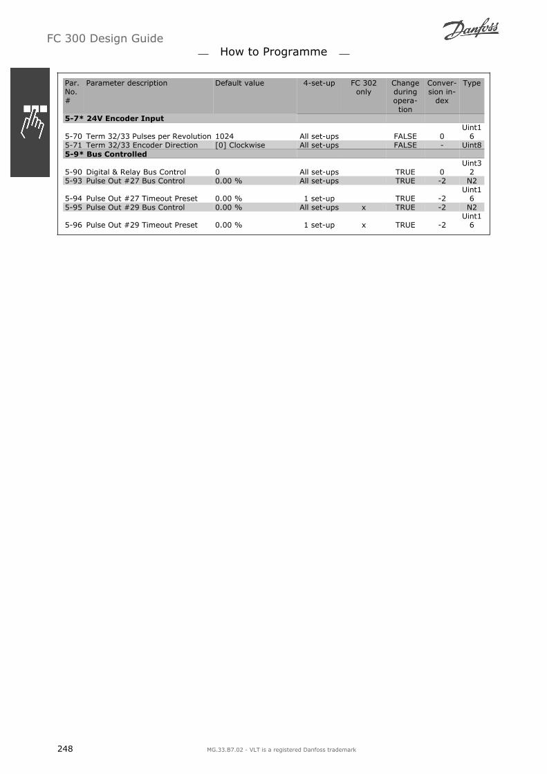
Par.No.#
Parameter description Default value 4-set-up FC 302only
Changeduringopera-tion
Conver-sion in-
dex
Type
5-7* 24V Encoder Input
5-70 Term 32/33 Pulses per Revolution 1024 All set-ups FALSE 0Uint1
65-71 Term 32/33 Encoder Direction [0] Clockwise All set-ups FALSE - Uint85-9* Bus Controlled
5-90 Digital & Relay Bus Control 0 All set-ups TRUE 0Uint3
25-93 Pulse Out #27 Bus Control 0.00 % All set-ups TRUE -2 N2
5-94 Pulse Out #27 Timeout Preset 0.00 % 1 set-up TRUE -2Uint1
65-95 Pulse Out #29 Bus Control 0.00 % All set-ups x TRUE -2 N2
5-96 Pulse Out #29 Timeout Preset 0.00 % 1 set-up x TRUE -2Uint1
6
FC 300 Design Guide How to Programme
248 MG.33.B7.02 - VLT is a registered Danfoss trademark

6-** Analog In/Out
Par.No.#
Parameter description Default value(SR = Size Related)
4-set-up FC 302only
Changeduringopera-tion
Conver-sion in-
dex
Type
6-0* Analog I/O Mode6-00 Live Zero Timeout Time 10 s All set-ups TRUE 0 Uint86-01 Live Zero Timeout Function [0] Off All set-ups TRUE - Uint86-1* Analog Input 16-10 Terminal 53 Low Voltage 0.07 V All set-ups TRUE -2 Int166-11 Terminal 53 High Voltage 10.00 V All set-ups TRUE -2 Int166-12 Terminal 53 Low Current 0.14 mA All set-ups TRUE -5 Int166-13 Terminal 53 High Current 20.00 mA All set-ups TRUE -5 Int16
6-14Terminal 53 Low Ref./Feedb. Val-ue SR All set-ups TRUE -3 Int32
6-15Terminal 53 High Ref./Feedb. Val-ue SR All set-ups TRUE -3 Int32
6-16 Terminal 53 Filter Time Constant 0.001 s All set-ups TRUE -3Uint1
66-2* Analog Input 26-20 Terminal 54 Low Voltage 0.07 V All set-ups TRUE -2 Int166-21 Terminal 54 High Voltage 10.00 V All set-ups TRUE -2 Int166-22 Terminal 54 Low Current 0.14 mA All set-ups TRUE -5 Int166-23 Terminal 54 High Current 20.00 mA All set-ups TRUE -5 Int16
6-24Terminal 54 Low Ref./Feedb. Val-ue SR All set-ups TRUE -3 Int32
6-25 Terminal 54 High Ref./Feedb. Val-ue SR All set-ups TRUE -3 Int32
6-26 Terminal 54 Filter Time Constant 0.001 s All set-ups TRUE -3Uint1
66-3* Analog Input 36-30 Terminal X30/11 Low Voltage 0.07 V All set-ups TRUE -2 Int166-31 Terminal X30/11 High Voltage 10.00 V All set-ups TRUE -2 Int166-34 Term. X30/11 Low Ref./Feedb.
Value SR All set-ups TRUE -3 Int326-35 Term. X30/11 High Ref./Feedb.
Value SR All set-ups TRUE -3 Int32
6-36Term. X30/11 Filter Time Con-stant 0.001 s All set-ups TRUE -3
Uint16
6-4* Analog Input 46-40 Terminal X30/12 Low Voltage 0.07 V All set-ups TRUE -2 Int166-41 Terminal X30/12 High Voltage 10.00 V All set-ups TRUE -2 Int166-44 Term. X30/12 Low Ref./Feedb.
Value SR All set-ups TRUE -3 Int326-45 Term. X30/12 High Ref./Feedb.
Value SR All set-ups TRUE -3 Int32
6-46Term. X30/12 Filter Time Con-stant 0.001 s All set-ups TRUE -3
Uint16
6-5* Analog Output 16-50 Terminal 42 Output - All set-ups TRUE - Uint86-51 Terminal 42 Output Min Scale 0.00 % All set-ups TRUE -2 Int166-52 Terminal 42 Output Max Scale 100.00 % All set-ups TRUE -2 Int166-53 Terminal 42 Output Bus Control 0.00 % All set-ups TRUE -2 N2
6-54Terminal 42 Output Timeout Pre-set 0.00 % 1 set-up TRUE -2
Uint16
6-6* Analog Output 26-60 Terminal X30/8 Output - All set-ups TRUE - Uint86-61 Terminal X30/8 Min. Scale 0.00 % All set-ups TRUE -2 Int166-62 Terminal X30/8 Max. Scale 100.00 % All set-ups TRUE -2 Int16
FC 300 Design Guide How to Programme
MG.33.B7.02 - VLT is a registered Danfoss trademark 249

7-** Controllers
Par.No.#
Parameter description Default value(SR = Size Related)
4-set-up FC 302only
Changeduringopera-tion
Conver-sion in-
dex
Type
7-0* Speed PID Ctrl.7-00 Speed PID Feedback Source - All set-ups FALSE - Uint8
7-02 Speed PID Proportional Gain SR All set-ups TRUE -3Uint1
6
7-03 Speed PID Integral Time SR All set-ups TRUE -4Uint3
2
7-04 Speed PID Differentiation Time SR All set-ups TRUE -4Uint1
6
7-05 Speed PID Diff. Gain Limit 5.0 N/A All set-ups TRUE -1Uint1
6
7-06 Speed PID Lowpass Filter Time 10.0 ms All set-ups TRUE -4Uint1
6
7-08 Speed PID Feed Forward Factor 0 % All set-ups FALSE 0Uint1
67-2* Process Ctrl. Feedb7-20 Process CL Feedback 1 Source [0] No function All set-ups TRUE - Uint87-22 Process CL Feedback 2 Source [0] No function All set-ups TRUE - Uint87-3* Process PID Ctrl.7-30 Process PID Normal/ Inverse Con-
trol [0] Normal All set-ups TRUE - Uint87-31 Process PID Anti Windup [1] On All set-ups TRUE - Uint8
7-32 Process PID Start Speed 0 RPM All set-ups TRUE 67Uint1
6
7-33 Process PID Proportional Gain 0.01 All set-ups TRUE -2Uint1
6
7-34 Process PID Integral Time 10000.00 s All set-ups TRUE -2Uint3
2
7-35 Process PID Differentiation Time 0.00 s All set-ups TRUE -2Uint1
6
7-36 Process PID Diff. Gain Limit 5.0 All set-ups TRUE -1Uint1
6
7-38 Process PID Feed Forward Factor 0 % All set-ups TRUE 0Uint1
67-39 On Reference Bandwidth 5 % All set-ups TRUE 0 Uint8
FC 300 Design Guide How to Programme
250 MG.33.B7.02 - VLT is a registered Danfoss trademark

8-** Comm. and Options
Par.No.#
Parameter description Default value 4-set-up FC 302only
Changeduringopera-tion
Conver-sion in-
dex
Type
8-0* General Settings
8-01 Control Site[0] Digital andctrl.word All set-ups TRUE - Uint8
8-02 Control Word Source - All set-ups TRUE - Uint8
8-03 Control Word Timeout Time 1.0 s 1 set-up TRUE -1Uint3
28-04 Control Word Timeout Function [0] Off 1 set-up TRUE - Uint88-05 End-of-Timeout Function [1] Resume set-up 1 set-up TRUE - Uint88-06 Reset Control Word Timeout [0] Do not reset All set-ups TRUE - Uint88-07 Diagnosis Trigger [0] Disable 2 set-ups TRUE - Uint88-1* Ctrl. Word Settings8-10 Control Word Profile [0] FC profile All set-ups TRUE - Uint88-13 Configurable Status Word STW [1] Profile Default All set-ups TRUE - Uint88-3* FC Port Settings8-30 Protocol [0] FC 1 set-up TRUE - Uint88-31 Address 1 1 set-up TRUE 0 Uint88-32 FC Port Baud Rate [2] 9600 Baud 1 set-up TRUE - Uint8
8-35 Minimum Response Delay 10 ms All set-ups TRUE -3Uint1
6
8-36 Max Response Delay 5000 ms 1 set-up TRUE -3Uint1
6
8-37 Max Inter-Char Delay 25 ms 1 set-up TRUE -3Uint1
68-4* FC MC protocol set
8-40 Telegram selection[1] Standard tele-gram 1 2 set-ups TRUE - Uint8
8-5* Digital/Bus8-50 Coasting Select [3] Logic OR All set-ups TRUE - Uint88-51 Quick Stop Select [3] Logic OR All set-ups TRUE - Uint88-52 DC Brake Select [3] Logic OR All set-ups TRUE - Uint88-53 Start Select [3] Logic OR All set-ups TRUE - Uint88-54 Reversing Select [3] Logic OR All set-ups TRUE - Uint88-55 Set-up Select [3] Logic OR All set-ups TRUE - Uint88-56 Preset Reference Select [3] Logic OR All set-ups TRUE - Uint88-9* Bus Jog
8-90 Bus Jog 1 Speed 100 RPM All set-ups TRUE 67Uint1
6
8-91 Bus Jog 2 Speed 200 RPM All set-ups TRUE 67Uint1
6
FC 300 Design Guide How to Programme
MG.33.B7.02 - VLT is a registered Danfoss trademark 251
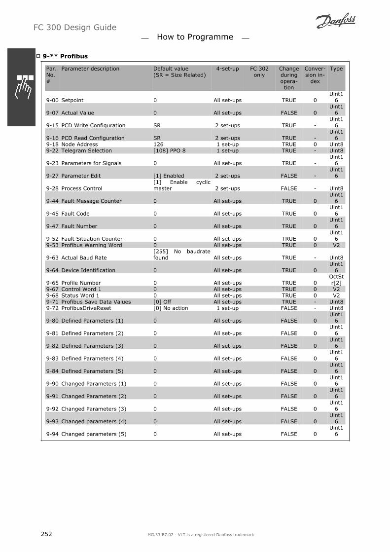
9-** Profibus
Par.No.#
Parameter description Default value(SR = Size Related)
4-set-up FC 302only
Changeduringopera-tion
Conver-sion in-
dex
Type
9-00 Setpoint 0 All set-ups TRUE 0Uint1
6
9-07 Actual Value 0 All set-ups FALSE 0Uint1
6
9-15 PCD Write Configuration SR 2 set-ups TRUE -Uint1
6
9-16 PCD Read Configuration SR 2 set-ups TRUE -Uint1
69-18 Node Address 126 1 set-up TRUE 0 Uint89-22 Telegram Selection [108] PPO 8 1 set-up TRUE - Uint8
9-23 Parameters for Signals 0 All set-ups TRUE -Uint1
6
9-27 Parameter Edit [1] Enabled 2 set-ups FALSE -Uint1
6
9-28 Process Control[1] Enable cyclicmaster 2 set-ups FALSE - Uint8
9-44 Fault Message Counter 0 All set-ups TRUE 0Uint1
6
9-45 Fault Code 0 All set-ups TRUE 0Uint1
6
9-47 Fault Number 0 All set-ups TRUE 0Uint1
6
9-52 Fault Situation Counter 0 All set-ups TRUE 0Uint1
69-53 Profibus Warning Word 0 All set-ups TRUE 0 V2
9-63 Actual Baud Rate[255] No baudratefound All set-ups TRUE - Uint8
9-64 Device Identification 0 All set-ups TRUE 0Uint1
6
9-65 Profile Number 0 All set-ups TRUE 0OctStr[2]
9-67 Control Word 1 0 All set-ups TRUE 0 V29-68 Status Word 1 0 All set-ups TRUE 0 V29-71 Profibus Save Data Values [0] Off All set-ups TRUE - Uint89-72 ProfibusDriveReset [0] No action 1 set-up FALSE - Uint8
9-80 Defined Parameters (1) 0 All set-ups FALSE 0Uint1
6
9-81 Defined Parameters (2) 0 All set-ups FALSE 0Uint1
6
9-82 Defined Parameters (3) 0 All set-ups FALSE 0Uint1
6
9-83 Defined Parameters (4) 0 All set-ups FALSE 0Uint1
6
9-84 Defined Parameters (5) 0 All set-ups FALSE 0Uint1
6
9-90 Changed Parameters (1) 0 All set-ups FALSE 0Uint1
6
9-91 Changed Parameters (2) 0 All set-ups FALSE 0Uint1
6
9-92 Changed Parameters (3) 0 All set-ups FALSE 0Uint1
6
9-93 Changed parameters (4) 0 All set-ups FALSE 0Uint1
6
9-94 Changed parameters (5) 0 All set-ups FALSE 0Uint1
6
FC 300 Design Guide How to Programme
252 MG.33.B7.02 - VLT is a registered Danfoss trademark

10-** CAN Fieldbus
Par.No. #
Parameter description Default value(SR = Size Re-lated)
4-set-up FC 302only
Changeduring op-
eration
Conver-sion in-
dex
Type
10-0* Common Settings10-00 CAN Protocol - 2 set-ups FALSE - Uint810-01 Baud Rate Select - 2 set-ups TRUE - Uint810-02 MAC ID SR 2 set-ups TRUE 0 Uint8
10-05Readout Transmit Error Coun-ter 0 All set-ups TRUE 0 Uint8
10-06 Readout Receive Error Counter 0 All set-ups TRUE 0 Uint810-07 Readout Bus Off Counter 0 All set-ups TRUE 0 Uint810-1* DeviceNet10-10 Process Data Type Selection - All set-ups TRUE - Uint810-11 Process Data Config Write SR 2 set-ups TRUE - Uint1610-12 Process Data Config Read SR 2 set-ups TRUE - Uint1610-13 Warning Parameter 0 All set-ups TRUE 0 Uint1610-14 Net Reference [0] Off 2 set-ups TRUE - Uint810-15 Net Control [0] Off 2 set-ups TRUE - Uint810-2* COS Filters10-20 COS Filter 1 0 All set-ups FALSE 0 Uint1610-21 COS Filter 2 0 All set-ups FALSE 0 Uint1610-22 COS Filter 3 0 All set-ups FALSE 0 Uint1610-23 COS Filter 4 0 All set-ups FALSE 0 Uint1610-3* Parameter Access10-30 Array Index 0 2 set-ups TRUE 0 Uint810-31 Store Data Values [0] Off All set-ups TRUE - Uint810-32 Devicenet Revision SR All set-ups TRUE 0 Uint1610-33 Store Always [0] Off 1 set-up TRUE - Uint810-34 DeviceNet Product Code SR 1 set-up TRUE 0 Uint1610-39 Devicenet F Parameters 0 All set-ups TRUE 0 Uint3210-5* CANopen10-50 Process Data Config Write. SR 2 set-ups TRUE - Uint1610-51 Process Data Config Read. SR 2 set-ups TRUE - Uint16
FC 300 Design Guide How to Programme
MG.33.B7.02 - VLT is a registered Danfoss trademark 253

13-** Smart Logic
Par.No. #
Parameter description Default value(SR = Size Related)
4-set-up FC 302only
Changeduringopera-
tion
Conver-sion in-
dex
Type
13-0* SLC Settings13-00 SL Controller Mode - 2 set-ups TRUE - Uint813-01 Start Event - 2 set-ups TRUE - Uint813-02 Stop Event - 2 set-ups TRUE - Uint813-03 Reset SLC [0] Do not reset SLC All set-ups TRUE - Uint813-1* Comparators13-10 Comparator Operand - 2 set-ups TRUE - Uint813-11 Comparator Operator - 2 set-ups TRUE - Uint813-12 Comparator Value SR 2 set-ups TRUE -3 Int3213-2* Timers13-20 SL Controller Timer SR 1 set-up TRUE -3 TimD13-4* Logic Rules13-40 Logic Rule Boolean 1 - 2 set-ups TRUE - Uint813-41 Logic Rule Operator 1 - 2 set-ups TRUE - Uint813-42 Logic Rule Boolean 2 - 2 set-ups TRUE - Uint813-43 Logic Rule Operator 2 - 2 set-ups TRUE - Uint813-44 Logic Rule Boolean 3 - 2 set-ups TRUE - Uint813-5* States13-51 SL Controller Event - 2 set-ups TRUE - Uint813-52 SL Controller Action - 2 set-ups TRUE - Uint8
FC 300 Design Guide How to Programme
254 MG.33.B7.02 - VLT is a registered Danfoss trademark

14-** Special Functions
Par.No. #
Parameter description Default value(SR = Size Related)
4-set-up FC 302only
Changeduringopera-tion
Conver-sion in-
dex
Type
14-0* Inverter Switching14-00 Switching Pattern [1] SFAVM All set-ups TRUE - Uint814-01 Switching Frequency - All set-ups TRUE - Uint814-03 Overmodulation [1] On All set-ups FALSE - Uint814-04 PWM Random [0] Off All set-ups TRUE - Uint814-1* Mains On/Off14-10 Mains Failure [0] No function All set-ups FALSE - Uint8
14-11 Mains Voltage at Mains Fault SR All set-ups TRUE 0Uint1
614-12 Function at Mains Imbalance [0] Trip All set-ups TRUE - Uint814-2* Trip Reset14-20 Reset Mode [0] Manual reset All set-ups TRUE - Uint8
14-21 Automatic Restart Time 10 s All set-ups TRUE 0Uint1
614-22 Operation Mode [0] Normal operation All set-ups TRUE - Uint8
14-23 Typecode Setting - 2 set-ups FALSE -Uint1
614-25 Trip Delay at Torque Limit 60 s All set-ups TRUE 0 Uint814-26 Trip Delay at Inverter Fault SR All set-ups TRUE 0 Uint814-28 Production Settings [0] No action All set-ups TRUE - Uint814-29 Service Code 0 All set-ups TRUE 0 Int3214-3* Current Limit Ctrl.
14-30Current Lim Cont, ProportionalGain 100 % All set-ups FALSE 0
Uint16
14-31Current Lim Contr, IntegrationTime 0.020 s All set-ups FALSE -3
Uint16
14-4* Energy Optimising14-40 VT Level 66 % All set-ups FALSE 0 Uint814-41 AEO Minimum Magnetisation 40 % All set-ups TRUE 0 Uint814-42 Minimum AEO Frequency 10 Hz All set-ups TRUE 0 Uint8
14-43 Motor Cosphi SR All set-ups TRUE -2Uint1
614-5* Environment14-50 RFI Filter [1] On 1 set-up x FALSE - Uint814-52 Fan Control [0] Auto All set-ups TRUE - Uint814-53 Fan Monitor [1] Warning All set-ups TRUE - Uint814-55 Output Filter [0] No Filter 1 set-up FALSE - Uint8
FC 300 Design Guide How to Programme
MG.33.B7.02 - VLT is a registered Danfoss trademark 255

15-** Drive Information
Par.No. #
Parameter description Default value(SR = Size Rela-ted)
4-set-up Changeduring op-
eration
Conver-sion index
Type
15-0* Operating Data15-00 Operating Hours 0 h All set-ups FALSE 74 Uint3215-01 Running Hours 0 h All set-ups FALSE 74 Uint3215-02 kWh Counter 0 kWh All set-ups FALSE 75 Uint3215-03 Power Up's 0 All set-ups FALSE 0 Uint3215-04 Over Temp's 0 All set-ups FALSE 0 Uint1615-05 Over Volt's 0 All set-ups FALSE 0 Uint1615-06 Reset kWh Counter [0] Do not reset All set-ups TRUE - Uint815-07 Reset Running Hours Counter [0] Do not reset All set-ups TRUE - Uint815-1* Data Log Settings15-10 Logging Source 0 2 set-ups TRUE - Uint1615-11 Logging Interval SR 2 set-ups TRUE -3 TimD15-12 Trigger Event [0] False 1 set-up TRUE - Uint815-13 Logging Mode [0] Log always 2 set-ups TRUE - Uint815-14 Samples Before Trigger 50 2 set-ups TRUE 0 Uint815-2* Historic Log15-20 Historic Log: Event 0 All set-ups FALSE 0 Uint815-21 Historic Log: Value 0 All set-ups FALSE 0 Uint3215-22 Historic Log: Time 0 ms All set-ups FALSE -3 Uint3215-3* Fault Log15-30 Fault Log: Error Code 0 All set-ups FALSE 0 Uint815-31 Fault Log: Value 0 All set-ups FALSE 0 Int1615-32 Fault Log: Time 0 s All set-ups FALSE 0 Uint3215-4* Drive Identification15-40 FC Type 0 All set-ups FALSE 0 VisStr[6]15-41 Power Section 0 All set-ups FALSE 0 VisStr[20]15-42 Voltage 0 All set-ups FALSE 0 VisStr[20]15-43 Software Version 0 All set-ups FALSE 0 VisStr[5]15-44 Ordered Typecode String 0 All set-ups FALSE 0 VisStr[40]15-45 Actual Typecode String 0 All set-ups FALSE 0 VisStr[40]15-46 Frequency Converter Ordering No 0 All set-ups FALSE 0 VisStr[8]15-47 Power Card Ordering No 0 All set-ups FALSE 0 VisStr[8]15-48 LCP Id No 0 All set-ups FALSE 0 VisStr[20]15-49 SW ID Control Card 0 All set-ups FALSE 0 VisStr[20]15-50 SW ID Power Card 0 All set-ups FALSE 0 VisStr[20]
15-51Frequency Converter Serial Num-ber 0 All set-ups FALSE 0 VisStr[10]
15-53 Power Card Serial Number 0 All set-ups FALSE 0 VisStr[19]15-6* Option Ident15-60 Option Mounted 0 All set-ups FALSE 0 VisStr[30]15-61 Option SW Version 0 All set-ups FALSE 0 VisStr[20]15-62 Option Ordering No 0 All set-ups FALSE 0 VisStr[8]15-63 Option Serial No 0 All set-ups FALSE 0 VisStr[18]15-70 Option in Slot A 0 All set-ups FALSE 0 VisStr[30]15-71 Slot A Option SW Version 0 All set-ups FALSE 0 VisStr[20]15-72 Option in Slot B 0 All set-ups FALSE 0 VisStr[30]15-73 Slot B Option SW Version 0 All set-ups FALSE 0 VisStr[20]15-74 Option in Slot C0 0 All set-ups FALSE 0 VisStr[30]15-75 Slot C0 Option SW Version 0 All set-ups FALSE 0 VisStr[20]15-76 Option in Slot C1 0 All set-ups FALSE 0 VisStr[30]15-77 Slot C1 Option SW Version 0 All set-ups FALSE 0 VisStr[20]15-9* Parameter Info15-92 Defined Parameters 0 All set-ups FALSE 0 Uint1615-93 Modified Parameters 0 All set-ups FALSE 0 Uint1615-99 Parameter Metadata 0 All set-ups FALSE 0 Uint16
FC 300 Design Guide How to Programme
256 MG.33.B7.02 - VLT is a registered Danfoss trademark
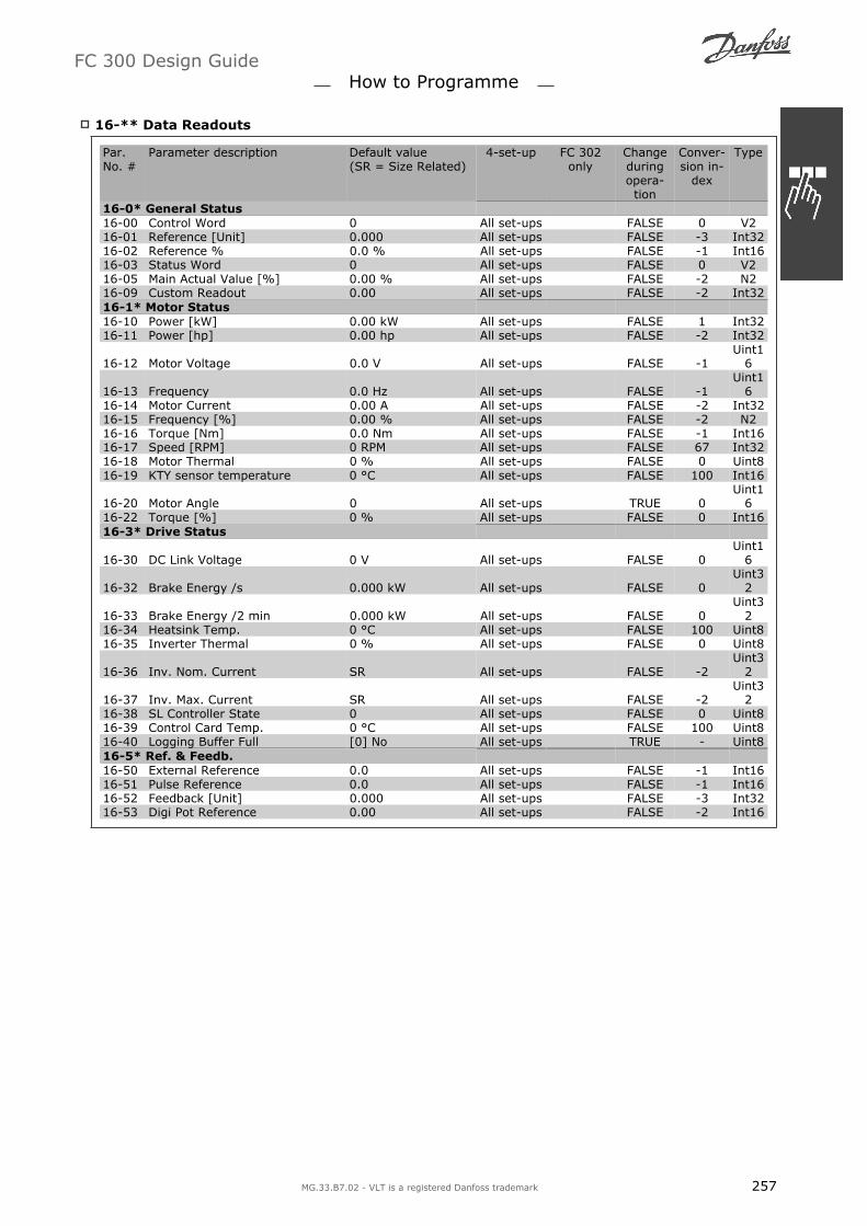
16-** Data Readouts
Par.No. #
Parameter description Default value(SR = Size Related)
4-set-up FC 302only
Changeduringopera-tion
Conver-sion in-
dex
Type
16-0* General Status16-00 Control Word 0 All set-ups FALSE 0 V216-01 Reference [Unit] 0.000 All set-ups FALSE -3 Int3216-02 Reference % 0.0 % All set-ups FALSE -1 Int1616-03 Status Word 0 All set-ups FALSE 0 V216-05 Main Actual Value [%] 0.00 % All set-ups FALSE -2 N216-09 Custom Readout 0.00 All set-ups FALSE -2 Int3216-1* Motor Status16-10 Power [kW] 0.00 kW All set-ups FALSE 1 Int3216-11 Power [hp] 0.00 hp All set-ups FALSE -2 Int32
16-12 Motor Voltage 0.0 V All set-ups FALSE -1Uint1
6
16-13 Frequency 0.0 Hz All set-ups FALSE -1Uint1
616-14 Motor Current 0.00 A All set-ups FALSE -2 Int3216-15 Frequency [%] 0.00 % All set-ups FALSE -2 N216-16 Torque [Nm] 0.0 Nm All set-ups FALSE -1 Int1616-17 Speed [RPM] 0 RPM All set-ups FALSE 67 Int3216-18 Motor Thermal 0 % All set-ups FALSE 0 Uint816-19 KTY sensor temperature 0 °C All set-ups FALSE 100 Int16
16-20 Motor Angle 0 All set-ups TRUE 0Uint1
616-22 Torque [%] 0 % All set-ups FALSE 0 Int1616-3* Drive Status
16-30 DC Link Voltage 0 V All set-ups FALSE 0Uint1
6
16-32 Brake Energy /s 0.000 kW All set-ups FALSE 0Uint3
2
16-33 Brake Energy /2 min 0.000 kW All set-ups FALSE 0Uint3
216-34 Heatsink Temp. 0 °C All set-ups FALSE 100 Uint816-35 Inverter Thermal 0 % All set-ups FALSE 0 Uint8
16-36 Inv. Nom. Current SR All set-ups FALSE -2Uint3
2
16-37 Inv. Max. Current SR All set-ups FALSE -2Uint3
216-38 SL Controller State 0 All set-ups FALSE 0 Uint816-39 Control Card Temp. 0 °C All set-ups FALSE 100 Uint816-40 Logging Buffer Full [0] No All set-ups TRUE - Uint816-5* Ref. & Feedb.16-50 External Reference 0.0 All set-ups FALSE -1 Int1616-51 Pulse Reference 0.0 All set-ups FALSE -1 Int1616-52 Feedback [Unit] 0.000 All set-ups FALSE -3 Int3216-53 Digi Pot Reference 0.00 All set-ups FALSE -2 Int16
FC 300 Design Guide How to Programme
MG.33.B7.02 - VLT is a registered Danfoss trademark 257
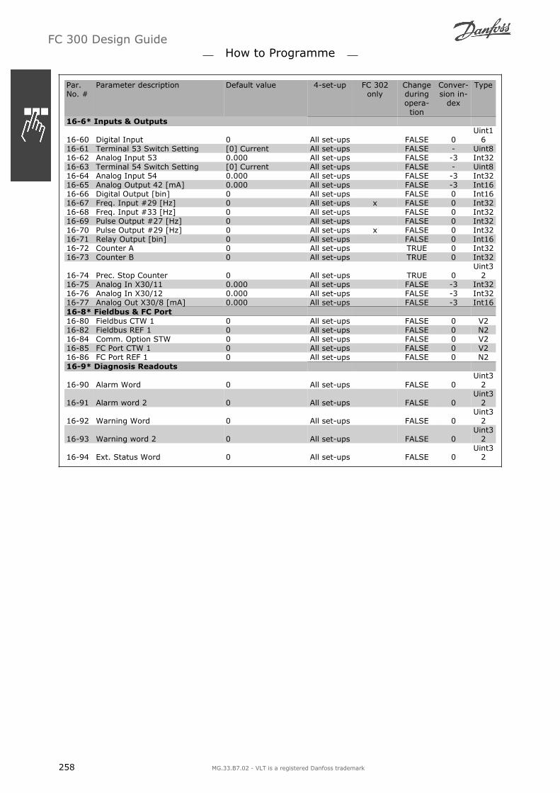
Par.No. #
Parameter description Default value 4-set-up FC 302only
Changeduringopera-tion
Conver-sion in-
dex
Type
16-6* Inputs & Outputs
16-60 Digital Input 0 All set-ups FALSE 0Uint1
616-61 Terminal 53 Switch Setting [0] Current All set-ups FALSE - Uint816-62 Analog Input 53 0.000 All set-ups FALSE -3 Int3216-63 Terminal 54 Switch Setting [0] Current All set-ups FALSE - Uint816-64 Analog Input 54 0.000 All set-ups FALSE -3 Int3216-65 Analog Output 42 [mA] 0.000 All set-ups FALSE -3 Int1616-66 Digital Output [bin] 0 All set-ups FALSE 0 Int1616-67 Freq. Input #29 [Hz] 0 All set-ups x FALSE 0 Int3216-68 Freq. Input #33 [Hz] 0 All set-ups FALSE 0 Int3216-69 Pulse Output #27 [Hz] 0 All set-ups FALSE 0 Int3216-70 Pulse Output #29 [Hz] 0 All set-ups x FALSE 0 Int3216-71 Relay Output [bin] 0 All set-ups FALSE 0 Int1616-72 Counter A 0 All set-ups TRUE 0 Int3216-73 Counter B 0 All set-ups TRUE 0 Int32
16-74 Prec. Stop Counter 0 All set-ups TRUE 0Uint3
216-75 Analog In X30/11 0.000 All set-ups FALSE -3 Int3216-76 Analog In X30/12 0.000 All set-ups FALSE -3 Int3216-77 Analog Out X30/8 [mA] 0.000 All set-ups FALSE -3 Int1616-8* Fieldbus & FC Port16-80 Fieldbus CTW 1 0 All set-ups FALSE 0 V216-82 Fieldbus REF 1 0 All set-ups FALSE 0 N216-84 Comm. Option STW 0 All set-ups FALSE 0 V216-85 FC Port CTW 1 0 All set-ups FALSE 0 V216-86 FC Port REF 1 0 All set-ups FALSE 0 N216-9* Diagnosis Readouts
16-90 Alarm Word 0 All set-ups FALSE 0Uint3
2
16-91 Alarm word 2 0 All set-ups FALSE 0Uint3
2
16-92 Warning Word 0 All set-ups FALSE 0Uint3
2
16-93 Warning word 2 0 All set-ups FALSE 0Uint3
2
16-94 Ext. Status Word 0 All set-ups FALSE 0Uint3
2
FC 300 Design Guide How to Programme
258 MG.33.B7.02 - VLT is a registered Danfoss trademark

17-** Motor Feedb.Option
Par.No. #
Parameter description Default value 4-set-up FC 300series
Changeduringopera-tion
Conver-sion in-
dex
Type
17-1* Inc. Enc. Interface17-10 Signal Type [1] RS422 (5V TTL) All set-ups FALSE - Uint8
17-11 Resolution (PPR) 1024 N/A All set-ups FALSE 0Uint1
617-2* Abs. Enc. Interface17-20 Protocol Selection [0] None All set-ups FALSE - Uint8
17-21 Resolution (Positions/Rev) ExpressionLimit All set-ups FALSE 0Uint3
217-24 SSI Data Length 13 N/A All set-ups TRUE 0 Uint8
17-25 Clock Rate 260 kHz All set-ups TRUE 3Uint1
617-26 SSI Data Format [0] Grey code All set-ups TRUE - Uint817-34 HIPERFACE Baudrate [4] 9600 All set-ups FALSE - Uint817-6* Monitoring and App.17-60 Encoder Positive Direction [0] Clockwise All set-ups FALSE - Uint817-61 Encoder Signal Monitoring [0] Disabled All set-ups TRUE - Uint8
FC 300 Design Guide How to Programme
MG.33.B7.02 - VLT is a registered Danfoss trademark 259

FC 300 Design Guide
260 MG.33.B7.02 - VLT is a registered Danfoss trademark

Options and Accessories
Danfoss offers a wide range of options and accessories for VLT AutomationDrive FC 300 Series.
Mounting of Option Modules in Slot B
The power to the frequency converter must be disconnected.
It is strongly recommended to make sure the parameter data is saved (i.e. by MCT10 software ) beforeoption modules are inserted/removed from the drive.
Remove the LCP (Local Control Panel), the terminal cover, and the LCP frame from the frequencyconverter.
Fit the MCB10x option card into slot B.
Connect the control cables and relieve the cable by the enclosed cable strips.* Remove the knock out in the extended LCP frame, so that the option will fit under the extendedLCP frame.
Fit the extended LCP frame and terminal cover.
Fit the LCP or blind cover in the extended LCP frame.
Connect power to the frequency converter.
Set up the input/output functions in the corresponding parameters, as mentioned in thesection General Technical Data.
0.25 - 7.5 kW IP20 0.25 - 7.5 kW IP 55and
11 - 22 kW IP21
General Purpose Input Output Module MCB 101
MCB 101 is used for extension of digital and analog inputs and outputs of FC 301 and FC 302 Automa-tionDrive.
Contents: MCB 101 must be fitted into slot B in the AutomationDrive. MCB 101 option module
Extended fixture for LCP
Terminal cover
FC 300 Design Guide Options and Accessories
MG.33.B7.02 - VLT is a registered Danfoss trademark 261

Galvanic Isolation In The MCB 101
Digital/analog inputs are galvanically isolated from other inputs/outputs on the MCB 101 and in the con-trol card of the drive. Digital/analog outputs in the MCB 101 are galvanically isolated from other inputs/outputs on the MCB 101, but not from these on the control card of the drive.
If the digital inputs 7, 8 or 9 are to be switched by use of the internal 24 V power supply (terminal 9) theconnection between terminal 1 and 5 which is illustrated in the drawing has to be established.
Principle Diagram
FC 300 Design Guide Options and Accessories
262 MG.33.B7.02 - VLT is a registered Danfoss trademark
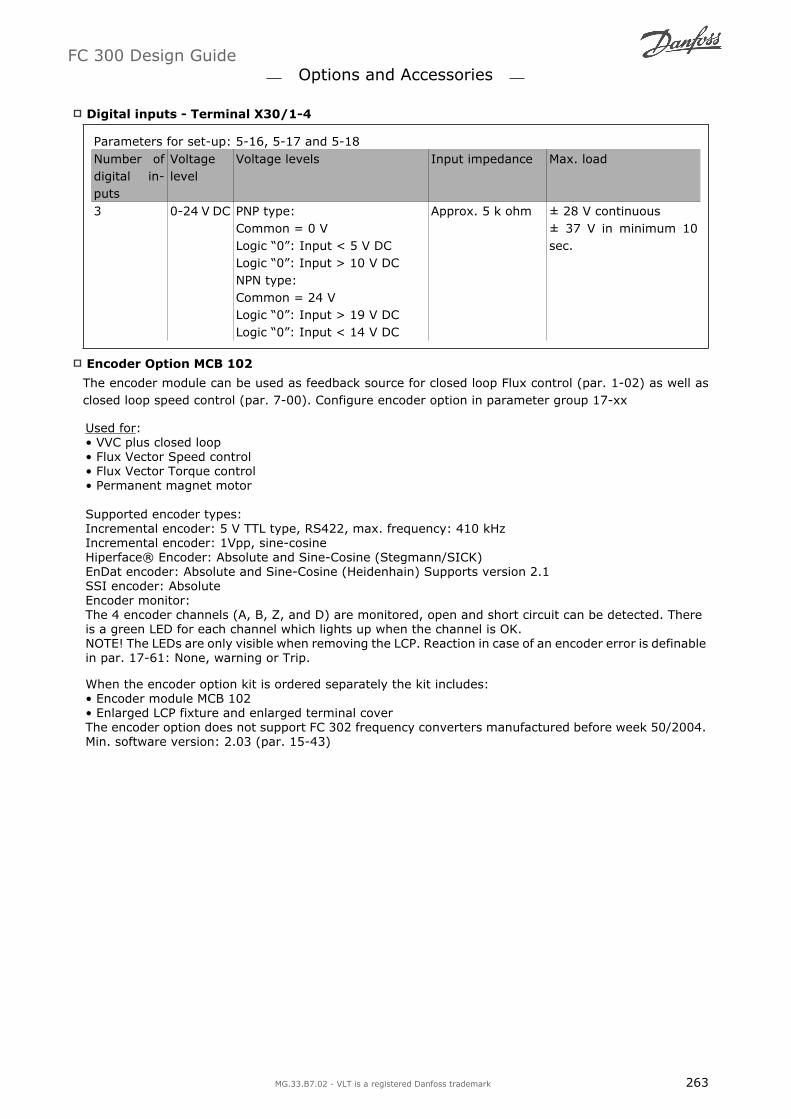
Digital inputs - Terminal X30/1-4
Parameters for set-up: 5-16, 5-17 and 5-18Number ofdigital in-puts
Voltagelevel
Voltage levels Input impedance Max. load
3 0-24 V DC PNP type:Common = 0 VLogic 0: Input < 5 V DCLogic 0: Input > 10 V DCNPN type:Common = 24 VLogic 0: Input > 19 V DCLogic 0: Input < 14 V DC
Approx. 5 k ohm ± 28 V continuous± 37 V in minimum 10sec.
Encoder Option MCB 102
The encoder module can be used as feedback source for closed loop Flux control (par. 1-02) as well asclosed loop speed control (par. 7-00). Configure encoder option in parameter group 17-xx
Used for: VVC plus closed loop Flux Vector Speed control Flux Vector Torque control Permanent magnet motor Supported encoder types: Incremental encoder: 5 V TTL type, RS422, max. frequency: 410 kHzIncremental encoder: 1Vpp, sine-cosineHiperface® Encoder: Absolute and Sine-Cosine (Stegmann/SICK)EnDat encoder: Absolute and Sine-Cosine (Heidenhain) Supports version 2.1SSI encoder: AbsoluteEncoder monitor:The 4 encoder channels (A, B, Z, and D) are monitored, open and short circuit can be detected. Thereis a green LED for each channel which lights up when the channel is OK.NOTE! The LEDs are only visible when removing the LCP. Reaction in case of an encoder error is definablein par. 17-61: None, warning or Trip.
When the encoder option kit is ordered separately the kit includes: Encoder module MCB 102 Enlarged LCP fixture and enlarged terminal coverThe encoder option does not support FC 302 frequency converters manufactured before week 50/2004.Min. software version: 2.03 (par. 15-43)
FC 300 Design Guide Options and Accessories
MG.33.B7.02 - VLT is a registered Danfoss trademark 263

Connec-torDesig-nationX31
IncrementalEncoder(please referto Graphic A)
SinCos EncoderHiperface®(please refer toGraphic B)
EnDat Encoder SSI Encoder Description
1 NC 24 V 24 V Output 2 NC 8 Vcc 8 V Output
3 5 VCC 5 Vcc 5 V 5 V Output 4 GND GND GND GND
5 A input +COS +COS A input A input 6 A inv input REFCOS REFCOS A input inv. A inv input
7 B input +SIN +SIN B input B input 8 B inv input REFSIN REFSIN B input inv. B inv input
9 Z input +Data RS485 Clock out Clock out Z input OR +DataRS485
10 Z inv input -Data RS485 Clock out inv. Clock out inv. Z input OR -DataRS485
11 NC NC Data in Data in Future use 12 NC NC Data in inv. Data in inv. Future use
Max. 5V on X31.5-12
FC 300 Design Guide Options and Accessories
264 MG.33.B7.02 - VLT is a registered Danfoss trademark

Resolver Option MCB 103
MCB 103 Resolver option is used for interfacingresolver motor feedback to FC 300 Automation-Drive. Resolvers are used basically as motor feed-back device for Permanent Magnet brushlesssynchronous motors. When the Resolver option isordered separately the kit includes:
Resolver option MCB 103
Enlarged LCP fixture and enlarged termi-nal cover
Selection of parameters: 17-5x resolver Inter-face.
The resolver interface must support one resolverwith the following specifications:
Resolver specifications:MCB 103 Resolver Option supports a various number of re-solver types.Number of poleson resolver
Par 17-50: 2 *2
Resolver inputvoltage
Par 17-51: 2.0 8.0 Vrms *7.0V
Carrier frequency(Ref. voltage)
Par 17-52: 2 15 kHz*10.0 kHz
Transformationratio
Par 17-53: 0.1 1.1 *0.5
Primary votlage 2-8 VrmsPrimary frequency 2 kHz - 15 kHzPrimary current Max. 50 mArmsSecondary inputvoltage
Max 8 Vrms
Secondary load App. 10 kΩCable length Up to 150 m
Note: Cables MUST be shielded and separatedfrom the motor cables.
NB!The resolver option MCB 103 can onlybe used with rotor-supplied resolvertypes. Stator-supplied resolvers can-not be used.
LED indicatorsLED 1 is on when the reference signal is OK to re-solverLED 2 is on when Cosinus signal is OK from re-solverLED 3 is on when Sinus signal is OK from resolver
The LEDs are active when par. 17-61 is set toWarning or Trip.
FC 300 Design Guide Options and Accessories
MG.33.B7.02 - VLT is a registered Danfoss trademark 265

Set-up exampleIn this example a Permanent Magnet (PM) Motor is used with resolver as speed feedback. A PM motormust usually operate in flux mode.Wiring:The max cable length is 150 m when a twisted pair type of cable is used.
NB!The screen of the resolver cable must be correct connected to the de-coupling plate and con-nected to chassis (earth) on the motor side.
NB!Always use screened motor cables and brake chopper cables.
Adjust following parameters:Par. 1-00 Configuration Mode Speed closed loop [1]Par. 1-01 Motor Control Principle Flux with feedback [3]Par. 1-10 Motor Construction PM, non salient SPM [1]Par. 1-24 Motor Current NameplatePar. 1-25 Motor Nominal Speed NameplatePar. 1-26 Motor Cont. Rated Torque NameplateAMA is not possible on PM motorsPar. 1-30 Stator Resistance Motor data sheetPar. 1-37 d-axis Inductance (Ld) Motor data sheet (mH)Par. 1-39 Motor Poles Motor data sheetPar. 1-40 Back EMF at 1000 RPM Motor data sheetPar. 1-41 Motor Angle Offset Motor data sheet (Usually zero)Par. 17-50 Poles Resolver data sheetPar. 17-51 Input Voltage Resolver data sheetPar. 17-52 Input Frequency Resolver data sheetPar. 17-53 Transformation Ratio Resolver data sheetPar. 17-59 Resolver Interface Enabled [1]
FC 300 Design Guide Options and Accessories
266 MG.33.B7.02 - VLT is a registered Danfoss trademark

Relay Option MCB 105
The MCB 105 option includes 3 pieces of SPDT contacts and must be fitted into option slot B.
Electrical Data:
Max terminal load (AC-1) 1) (Resistive load) 240 V AC 2A
Max terminal load (AC-15 ) 1) (Inductive load @ cosφ 0.4) 240 V AC 0.2 A
Max terminal load (DC-1) 1) (Resistive load) 24 V DC 1 A
Max terminal load (DC-13) 1) (Inductive load) 24 V DC 0.1 AMin terminal load (DC) 5 V 10 mA
Max switching rate at rated load/min load 6 min-1/20 sec-1
1) IEC 947 part 4 and 5
When the relay option kit is ordered separately the kit includes: Relay Module MCB 105
Enlarged LCP fixture and enlarged terminal cover
Label for covering access to switches S201, S202 and S801
Cable strips for fastening cables to relay module
The relay option does not support FC 302 frequency converters manufactured before week 50/2004.Min. software version: 2.03 (par. 15-43).
≤ 7.5 kWIMPORTANT1. The label MUST be placed on the LCP frame as shown (UL approved).
FC 300 Design Guide Options and Accessories
MG.33.B7.02 - VLT is a registered Danfoss trademark 267

11-22 kWIMPORTANT1. The label MUST be placed on the LCP frame as shown (UL approved).
Warning Dual supply
How to add the MCB 105 option: The power to the frequency converter must be disconnected.
The power to the live part connections on relay terminals must be disconnected.
Remove the LCP, the terminal cover and the LCP fixture from the FC 30x.
Fit the MCB 105 option in slot B.
Connect the control cables and fasten the cables with the enclosed cable strips.
Make sure the length of the stripped wire is correct (see the following drawing).
Do not mix live parts (high voltage) with control signals (PELV).
Fit the enlarged LCP fixture and enlarged terminal cover.
Replace the LCP.
Connect power to the frequency converter.
Select the relay functions in par. 5-40 [6-8], 5-41 [6-8] and 5-42 [6-8].
NB (Array [6] is relay 7, array [7] is relay 8, and array [8] is relay 9)
FC 300 Design Guide Options and Accessories
268 MG.33.B7.02 - VLT is a registered Danfoss trademark

Do not combine low voltage parts and PELV systems.
FC 300 Design Guide Options and Accessories
MG.33.B7.02 - VLT is a registered Danfoss trademark 269

24 V Back-Up Option MCB 107 (Option D)
External 24 V DC Supply
An external 24 V DC supply can be installed for low-voltage supply to the control card and any optioncard installed. This enables full operation of the LCP (including the parameter setting) without connectionto mains.
External 24 V DC supply specification:Input voltage range 24 V DC ±15 % (max. 37 V in 10 s)Max. input current 2.2 AAverage input current for FC 302 0.9 AMax cable length 75 mInput capacitance load < 10 uFPower-up delay < 0.6 sThe inputs are protected.
Terminal numbers:Terminal 35: - external 24 V DC supply .
Terminal 36: + external 24 V DC supply.
Follow these steps:1. Remove the LCP or Blind Cover
2. Remove the Terminal Cover
3. Remove the Cable Decoupling Plate andthe plastic cover underneath
4. Insert the 24 V DC Back-up External Sup-ply Option in the Option Slot
5. Mount the Cable Decoupling Plate
6. Attach the Terminal Cover and the LCP orBlind Cover.
When MCB 107, 24 V back-up option is supplyingthe control circuit, the internal 24 V supply is au-tomatically disconnected.
Connection to 24 V back-up supplier (≤ 7.5 kW).
Connection to 24 V back-up supplier (11-22 kW).
FC 300 Design Guide Options and Accessories
270 MG.33.B7.02 - VLT is a registered Danfoss trademark

Brake Resistors
Brake resistors are used in applications where high dynamics are needed or a high inertia load has to bestopped. The brake resistor is used to remove the energy from the DC link in the frequency converter.
Code numbers for brake resistors: See section Hot to Order.
Remote mounting Kit for LCP
The Local Control Panel can be moved to the frontof a cabinet by using the remote build in kit. Theenclosure is the IP65. The fastening screws mustbe tightened with a torque of max. 1 Nm.
Technical data Enclosure: IP 65 frontMax. cable length between VLT andunit: 3 mCommunication std: RS 485
IP 21/IP 4X/ TYPE 1 Enclosure Kit
IP 20/IP 4X top/ TYPE 1 is an optional enclosure element available for IP 20 Compact units.If the enclosure kit is used, an IP 20 unit is upgraded to comply with enclosure IP 21/ 4X top/TYPE 1.
The IP 4X top can be applied to all standard IP 20 FC 30X variants.
IP 21/Type 1 Enclosure Kit
A Top coverB BrimC Base partD Base coverE Screw(s)Place the top cover as shown. If an A or B optionis used the brim must be fitted to cover the topinlet. Place the base part C at the bottom of thedrive and use the clamps from the accessory bagto correctly fasten the cables. Holes for cableglands:Size A2: 2x PG16 (½) 3xPG21 (3/4)Size A3: 3xPG16 (½) 3xPG21 (3/4)
LC Filters
When a motor is controlled by a frequency converter, resonance noise will be heard from the motor. Thisnoise, which is the result of the design of the motor, arises every time an inverter switch in the frequencyconverter is activated. The frequency of the resonance noise thus corresponds to the switching frequencyof the frequency converter.
FC 300 Design Guide Options and Accessories
MG.33.B7.02 - VLT is a registered Danfoss trademark 271

For the FC 300 Series, Danfoss can supply an LC filter to dampen the acoustic motor noise.
The filter reduces the ramp-up time of the voltage, the peak load voltage UPEAK and the ripple current∆I to the motor, which means that current and voltage become almost sinusoidal. Consequently, theacoustic motor noise is reduced to a minimum.
The ripple current in the LC Filter coils, will also cause some noise. Solve the problem by integrating thefilter in a cabinet or similar.
FC 300 Design Guide Options and Accessories
272 MG.33.B7.02 - VLT is a registered Danfoss trademark
RS-485 Installation and Set-up
RS-485 Installation and Set-up
Overview
RS-485 is a two-wire bus interface compatible with multi-drop network topology, i.e. nodes can be con-nected as a bus, or via drop cables from a common trunk line. A total of 32 nodes can be connected toone network segment.Network segments are divided up by repeaters. Please note that each repeater functions as a node withinthe segment in which it is installed. Each node connected within a given network must have a uniquenode address, across all segments.Terminate each segment at both ends, using either the termination switch (S801) of the frequency con-verters or a biased termination resistor network. Always use screened twisted pair (STP) cable for buscabling, and always follow good common installation practice.Low-impedance ground connection of the screen at every node is very important, including at high fre-quencies. This can be achieved by connecting a large surface of the screen to ground, for example bymeans of a cable clamp or a conductive cable gland. It may be necessary to apply potential-equalizingcables to maintain the same ground potential throughout the network, particularly in installations wherethere are long lengths of cable.To prevent impedance mismatch, always use the same type of cable throughout the entire network. Whenconnecting a motor to the frequency converter, always use screened motor cable.
Cable: Screened twisted pair (STP)Impedance: 120 OhmCable length: Max. 1200 m (including drop lines)Max. 500 m station-to-station
FC 300 Design Guide
MG.33.B7.02 - VLT is a registered Danfoss trademark 273

Network Connection
Connect the frequency converter to the RS-485network as follows (see also diagram):
1. Connect signal wires to terminal 68 (P+)and terminal 69 (N-) on the main controlboard of the frequency converter.
2. Connect the cable screen to the cableclamps.
NB!Screened, twisted-pair cables are rec-ommended in order to reduce noisebetween conductors.
Network Terminal Connection
FC 300 Hardware Setup
Use the terminator dip switch on the main controlboard of the frequency converter to terminate theRS-485 bus.
NB!The factory setting for the dip switch isOFF.
Terminator Switch Factory Setting
FC 300 Design Guide RS-485 Installation and Set-up
274 MG.33.B7.02 - VLT is a registered Danfoss trademark
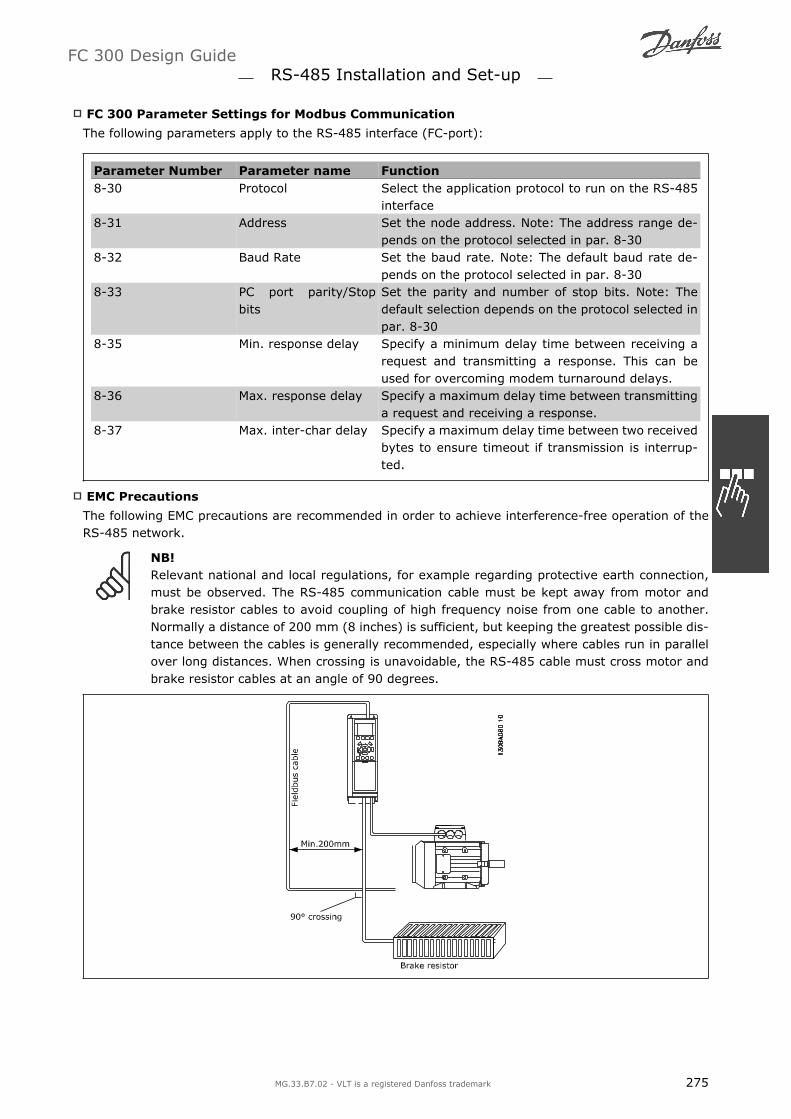
FC 300 Parameter Settings for Modbus Communication
The following parameters apply to the RS-485 interface (FC-port):
Parameter Number Parameter name Function8-30 Protocol Select the application protocol to run on the RS-485
interface8-31 Address Set the node address. Note: The address range de-
pends on the protocol selected in par. 8-308-32 Baud Rate Set the baud rate. Note: The default baud rate de-
pends on the protocol selected in par. 8-308-33 PC port parity/Stop
bitsSet the parity and number of stop bits. Note: Thedefault selection depends on the protocol selected inpar. 8-30
8-35 Min. response delay Specify a minimum delay time between receiving arequest and transmitting a response. This can beused for overcoming modem turnaround delays.
8-36 Max. response delay Specify a maximum delay time between transmittinga request and receiving a response.
8-37 Max. inter-char delay Specify a maximum delay time between two receivedbytes to ensure timeout if transmission is interrup-ted.
EMC Precautions
The following EMC precautions are recommended in order to achieve interference-free operation of theRS-485 network.
NB!Relevant national and local regulations, for example regarding protective earth connection,must be observed. The RS-485 communication cable must be kept away from motor andbrake resistor cables to avoid coupling of high frequency noise from one cable to another.Normally a distance of 200 mm (8 inches) is sufficient, but keeping the greatest possible dis-tance between the cables is generally recommended, especially where cables run in parallelover long distances. When crossing is unavoidable, the RS-485 cable must cross motor andbrake resistor cables at an angle of 90 degrees.
FC 300 Design Guide RS-485 Installation and Set-up
MG.33.B7.02 - VLT is a registered Danfoss trademark 275

FC Protocol Overview
The FC protocol, also referred to as FC bus or Standard bus, is the Danfoss Drives standard fieldbus. Itdefines an access technique according to the master-slave principle for communications via a serial bus.One master and a maximum of 126 slaves can be connected to the bus. The individual slaves are selectedby the master via an address character in the telegram. A slave itself can never transmit without firstbeing requested to do so, and direct message transfer between the individual slaves is not possible.Communications occur in the half-duplex mode.The master function cannot be transferred to another node (single-master system).
The physical layer is RS-485, thus utilizing the RS-485 port built into the frequency converter. The FCprotocol supports different telegram formats; a short format of 8 bytes for process data, and a longformat of 16 bytes that also includes a parameter channel. A third telegram format is used for texts.
Network Configuration
FC 300 Frequency Converter Set-up
Set the following parameters to enable the FC protocol for the FC 300.
Parameter Number Parameter name Setting8-30 Protocol FC8-31 Address 1 - 1268-32 Baud Rate 2400 - 1152008-33 Parity/Stop bits Even parity, 1 stop bit (default)
FC 300 Design Guide RS-485 Installation and Set-up
276 MG.33.B7.02 - VLT is a registered Danfoss trademark
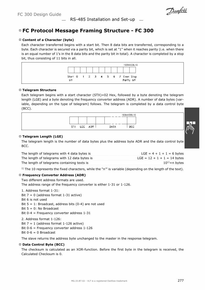
FC Protocol Message Framing Structure - FC 300
Content of a Character (byte)
Each character transferred begins with a start bit. Then 8 data bits are transferred, corresponding to abyte. Each character is secured via a parity bit, which is set at "1" when it reaches parity (i.e. when thereis an equal number of 1s in the 8 data bits and the parity bit in total). A character is completed by a stopbit, thus consisting of 11 bits in all.
Telegram Structure
Each telegram begins with a start character (STX)=02 Hex, followed by a byte denoting the telegramlength (LGE) and a byte denoting the frequency converter address (ADR). A number of data bytes (var-iable, depending on the type of telegram) follows. The telegram is completed by a data control byte(BCC).
Telegram Length (LGE)
The telegram length is the number of data bytes plus the address byte ADR and the data control byteBCC.
The length of telegrams with 4 data bytes is LGE = 4 + 1 + 1 = 6 bytesThe length of telegrams with 12 data bytes is LGE = 12 + 1 + 1 = 14 bytes
The length of telegrams containing texts is 101)+n bytes
1) The 10 represents the fixed characters, while the n is variable (depending on the length of the text).
Frequency Converter Address (ADR)
Two different address formats are used.The address range of the frequency converter is either 1-31 or 1-126.
1. Address format 1-31:Bit 7 = 0 (address format 1-31 active)Bit 6 is not usedBit 5 = 1: Broadcast, address bits (0-4) are not usedBit 5 = 0: No BroadcastBit 0-4 = Frequency converter address 1-31
2. Address format 1-126:Bit 7 = 1 (address format 1-126 active)Bit 0-6 = Frequency converter address 1-126Bit 0-6 = 0 Broadcast
The slave returns the address byte unchanged to the master in the response telegram.
Data Control Byte (BCC)
The checksum is calculated as an XOR-function. Before the first byte in the telegram is received, theCalculated Checksum is 0.
FC 300 Design Guide RS-485 Installation and Set-up
MG.33.B7.02 - VLT is a registered Danfoss trademark 277

The Data Field
The structure of data blocks depends on the type of telegram. There are three telegram types, and thetype applies for both control telegrams (master=>slave) and response telegrams (slave=>master).
The three types of telegram are:
Process block (PCD):The PCD is made up of a data block of four bytes (2 words) and contains:- Control word and reference value (from master to slave)- Status word and present output frequency (from slave to master).
Parameter block:The parameter block is used to transfer parameters between master and slave. The data block is madeup of 12 bytes (6 words) and also contains the process block.
Text block:The text block is used to read or write texts via the data block.
The PKE Field
The PKE field contains two sub-fields: Parameter command and response AK, and Parameter numberPNU:
Bits no. 12-15 transfer parameter commands from master to slave and return processed slave responsesto the master.
FC 300 Design Guide RS-485 Installation and Set-up
278 MG.33.B7.02 - VLT is a registered Danfoss trademark

Parameter commands master ⇒ slaveBit no. Parameter command15 14 13 120 0 0 0 No command0 0 0 1 Read parameter value0 0 1 0 Write parameter value in RAM (word)0 0 1 1 Write parameter value in RAM (double word)1 1 0 1 Write parameter value in RAM and EEprom (double word)1 1 1 0 Write parameter value in RAM and EEprom (word)1 1 1 1 Read/write text
Response slave ⇒masterBit no. Response15 14 13 120 0 0 0 No response0 0 0 1 Parameter value transferred (word)0 0 1 0 Parameter value transferred (double word)0 1 1 1 Command cannot be performed1 1 1 1 text transferred
If the command cannot be performed, the slave sends this response:0111 Command cannot be performed- and issues the following fault report in the parameter value (PWE):
PWE low (Hex) Fault Report0 The parameter number used does not exit1 There is no write access to the defined parameter2 Data value exceeds the parameter's limits3 The sub index used does not exit4 The parameter is not the array type5 The data type does not match the defined parameter11 Data change in the defined parameter is not possible in the frequency conver-
ter's present mode. Certain parameters can only be changed when the motoris turned off
82 There is no bus access to the defined parameter83 Data change is not possible because factory setup is selected
Parameter Number (PNU)
Bits no. 0-11 transfer parameter numbers. The function of the relevant parameter is defined in the pa-rameter description in the chapter How to Programme.
Index (IND)
The index is used together with the parameter number to read/write-access parameters with an index,e.g. par. 15-30 Error Code. The index consists of 2 bytes, a low byte and a high byte.
NB!Only the low byte is used as an index.
FC 300 Design Guide RS-485 Installation and Set-up
MG.33.B7.02 - VLT is a registered Danfoss trademark 279

Parameter Value (PWE)
The parameter value block consists of 2 words (4 bytes), and the value depends on the defined command(AK). The master prompts for a parameter value when the PWE block contains no value. To change aparameter value (write), write the new value in the PWE block and send from the master to the slave.
When a slave responds to a parameter request (read command), the present parameter value in the PWEblock is transferred and returned to the master. If a parameter contains not a numerical value but severaldata options, e.g. par. 0-01 Language where [0] corresponds to English, and [4] corresponds to Danish,select the data value by entering the value in the PWE block. See Example - Selecting a data value. Serialcommunication is only capable of reading parameters containing data type 9 (text string).
Parameters 15-40 to 15-53 contain data type 9.For example, read the unit size and mains voltage range in par. 15-40 FC Type. When a text string istransferred (read), the length of the telegram is variable, and the texts are of different lengths. Thetelegram length is defined in the second byte of the telegram, LGE. When using text transfer the indexcharacter indicates whether it is a read or a write command.
To read a text via the PWE block, set the parameter command (AK) to F Hex. The index character high-byte must be 4.
Some parameters contain text that can be written to via the serial bus. To write a text via the PWE block,set the parameter command (AK) to F Hex. The index characters high-byte must be 5.
Data Types Supported by FC 300
Unsigned means that there is no operational signin the telegram.
Data types Description3 Integer 164 Integer 325 Unsigned 86 Unsigned 167 Unsigned 329 Text string10 Byte string13 Time difference33 Reserved35 Bit sequence
Conversion
The various attributes of each parameter are dis-played in the section Factory Settings. Parametervalues are transferred as whole numbers only.Conversion factors are therefore used to transferdecimals.
Par. 4-12 Motor Speed, Low Limit has a conver-sion factor of 0.1.To preset the minimum frequency to 10 Hz, trans-fer the value 100. A conversion factor of 0.1
means that the value transferred is multiplied by0.1. The value 100 is thus perceived as 10.0.
FC 300 Design Guide RS-485 Installation and Set-up
280 MG.33.B7.02 - VLT is a registered Danfoss trademark

Conversion tableConversion index Conversion factor74 0.12 1001 100 1-1 0.1-2 0.01-3 0.001-4 0.0001-5 0.00001
Process Words (PCD)
The block of process words is divided into two blocks of 16 bits, which always occur in the defined se-quence.
PCD 1 PCD 2Control telegram (master⇒ Control word slave) Reference-valueControl telegram (slave ⇒master) Status word Present outp. frequency
FC 300 Design Guide RS-485 Installation and Set-up
MG.33.B7.02 - VLT is a registered Danfoss trademark 281

Examples
Writing a parameter value
Change par. 4-14 Motor Speed High Limit [Hz] to 100 Hz.Write the data in EEPROM.
PKE = E19E Hex - Write single word in par.4-14 Motor Speed High Limit [Hz]IND = 0000 HexPWEHIGH = 0000 HexPWELOW = 03E8 Hex - Data value 1000, corre-sponding to 100 Hz, see Conversion.
The telegram will look like this:
Note: Parameter 4-14 is a single word, and theparameter command for write in EEPROM is E.Parameter number 414 is 19E in hexadecimal.
The response from the slave to the master will be:
Reading a parameter value
Read the value in par. 3-41 Ramp 1 Up Time.
PKE = 1155 Hex - Read parameter value in par.3-41 Ramp 1 Up TimeIND = 0000 HexPWEHIGH = 0000 HexPWELOW = 0000 Hex
If the value in par. 3-41 Ramp 1 Up Time is 10 s,the response from the slave to the master will be:
NB!3E8 Hex corresponds to 1000 decimal. The conversion index for par. 3-41 is -2, i.e. 0.01.
Danfoss FC Control Profile
Control Word According to FC Profile (Par.8-10 = FC profile)
FC 300 Design Guide RS-485 Installation and Set-up
282 MG.33.B7.02 - VLT is a registered Danfoss trademark

Bit Bit value = 0 Bit value = 100 Reference value external selection lsb01 Reference value external selection msb02 DC brake Ramp03 Coasting No coasting04 Quick stop Ramp05 Hold output frequency use ramp06 Ramp stop Start07 No function Reset08 No function Jog09 Ramp 1 Ramp 210 Data invalid Data valid11 No function Relay 01 active12 No function Relay 02 active13 Parameter set-up selection lsb14 Parameter set-up selection msb15 No function Reverse
Explanation of the Control Bits
Bits 00/01Bits 00 and 01 are used to choose between the four reference values, which are pre-programmed in par.3-10 Preset reference according to the following table:
Programmed ref. value Par. Bit 01 Bit 001 3-10 [0] 0 02 3-10 [1] 0 13 3-10 [2] 1 04 3-10 [3] 1 1
NB!Make a selection in par. 8-56 PresetReference Select to define how Bit00/01 gates with the correspondingfunction on the digital inputs.
Bit 02, DC brake :Bit 02 = 0 leads to DC braking and stop. Set braking current and duration in par. 2-01 DC Brake Cur-rent and 2-02 DC Braking Time . Bit 02 = 1 leads to ramping.
Bit 03, Coasting :Bit 03 = 0: The frequency converter immediately "lets go" of the motor, (the output transistors are "shutoff") and it coasts to a standstill. Bit 03 = 1: The frequency converter starts the motor if the otherstarting conditions are met.
NB!Make a selection in par. 8-50 Coasting Select to define how Bit 03 gates with the correspond-ing function on a digital input.
Bit 04, Quick stop:Bit 04 = 0: Makes the motor speed ramp down to stop (set in par. 3-81 Quick Stop Ramp Time.
Bit 05, Hold output frequencyBit 05 = 0: The present output frequency (in Hz) freezes. Change the frozen output frequency only bymeans of the digital inputs (par. 5-10 to 5-15) programmed to Speed up and Slow down.
NB!If Freeze output is active, the frequency converter can only be stopped by the following:
Bit 03 Coasting stop
FC 300 Design Guide RS-485 Installation and Set-up
MG.33.B7.02 - VLT is a registered Danfoss trademark 283

Bit 02 DC braking
Digital input (par. 5-10 to 5-15) programmed to DC braking, Coasting stop, or Re-set and coasting stop.
Bit 06, Ramp stop/start:Bit 06 = 0: Causes a stop and makes the motor speed ramp down to stop via the selected ramp downpar. Bit 06 = 1: Permits the frequency converter to start the motor, if the other starting conditions aremet.
NB!Make a selection in par. 8-53 Start Select to define how Bit 06 Ramp stop/start gates with thecorresponding function on a digital input.
Bit 07, Reset: Bit 07 = 0: No reset. Bit 07 = 1: Resets a trip. Reset is activated on the signals leadingedge, i.e. when changing from logic 0 to logic 1.
Bit 08, Jog :Bit 08 = 1: The output frequency is determined by par. 3-19 Jog Speed.
Bit 09, Selection of ramp 1/2:Bit 09 = "0": Ramp 1 is active (par. 3-40 to 3-47). Bit 09 = "1": Ramp 2 (par. 3-50 to 3-57) is active.
Bit 10, Data not valid/Data valid:Tell the frequency converter whether to use or ignore the control word. Bit 10 = 0: The control word isignored. Bit 10 = 1: The control word is used. This function is relevant because the telegram alwayscontains the control word, regardless of the telegram type. Thus, you can turn off the control word if youdo not want to use it when updating or reading parameters.
Bit 11, Relay 01:Bit 11 = "0": Relay not activated. Bit 11 = "1": Relay 01 activated provided that Control word bit 11 ischosen in par. 5-40 Function relay.
Bit 12, Relay 04:Bit 12 = "0": Relay 04 is not activated. Bit 12 = "1": Relay 04 is activated provided that Control word bit12 is chosen in par. 5-40 Function relay.
Bit 13/14, Selection of set-up:Use bits 13 and 14 to choose from the four menuset-ups according to the shown table: .
Set-up Bit 14 Bit 131 0 02 0 13 1 04 1 1
The function is only possible when Multi Set-Upsis selected in par. 0-10 Active Set-Up
NB!Make a selection in par. 8-55 Set-upselect to define how Bit 13/14 gateswith the corresponding function on thedigital inputs.
Bit 15 Reverse:Bit 15 = 0: No reversing. Bit 15 = 1: Reversing. In the default setting, reversing is set to digital in par.8-54 Reversing Select. Bit 15 causes reversing only when Ser. communication, Logic or or Logic and isselected.
FC 300 Design Guide RS-485 Installation and Set-up
284 MG.33.B7.02 - VLT is a registered Danfoss trademark

Status Word According to FC Profile (STW) (Par. 8-10 = FC profile)
Bit Bit = 0 Bit = 100 Control not ready Control ready01 Drive not ready Drive ready02 Coasting Enable03 No error Trip04 No error Error (no trip)05 Reserved -06 No error Triplock07 No warning Warning08 Speed ≠ reference Speed = reference09 Local operation Bus control10 Out of frequency limit Frequency limit OK11 No operation In operation12 Drive OK Stopped, auto start13 Voltage OK Voltage exceeded14 Torque OK Torque exceeded15 Timer OK Timer exceeded
Explanation of the Status BitsBit 00, Control not ready/ready:Bit 00 = 0: The frequency converter trips. Bit 00 = 1: The frequency converter controls are ready butthe power component does not necessarily receive any power supply (in case of external 24 V supply tocontrols).
Bit 01, Drive ready:Bit 01 = 1: The frequency converter is ready for operation but the coasting command is active via thedigital inputs or via serial communication.
Bit 02, Coasting stop:Bit 02 = 0: The frequency converter releases the motor. Bit 02 = 1: The frequency converter startsthe motor with a start command.
Bit 03, No error/trip:Bit 03 = 0 : The frequency converter is not in fault mode. Bit 03 = 1: The frequency converter trips.To re-establish operation, enter [Reset].
Bit 04, No error/error (no trip):Bit 04 = 0: The frequency converter is not in fault mode. Bit 04 = 1: The frequency converter showsan error but does not trip.
Bit 05, Not used:Bit 05 is not used in the status word.
Bit 06, No error / triplock:Bit 06 = 0: The frequency converter is not in fault mode. Bit 06 = 1: The frequency converter is trippedand locked.
Bit 07, No warning/warning:Bit 07 = 0: There are no warnings. Bit 07 = 1: A warning has occurred.
FC 300 Design Guide RS-485 Installation and Set-up
MG.33.B7.02 - VLT is a registered Danfoss trademark 285

Bit 08, Speed≠ reference/speed = reference:Bit 08 = 0: The motor is running but the present speed is different from the preset speed reference. Itmight e.g. be the case when the speed ramps up/down during start/stop. Bit 08 = 1: The motor speedmatches the preset speed reference.
Bit 09, Local operation/bus control:Bit 09 = 0: [STOP/RESET] is activate on the control unit or Local control in par. 3-13 Reference Site isselected. You cannot control the frequency converter via serial communication. Bit 09 = 1 It is possibleto control the frequency converter via the fieldbus/ serial communication.
Bit 10, Out of frequency limit:Bit 10 = 0: The output frequency has reached the value in par. 4-11 Motor Speed Low Limit or par. 4-13Motor Speed High Limit. Bit 10 = "1": The output frequency is within the defined limits.
Bit 11, No operation/in operation:Bit 11 = 0: The motor is not running. Bit 11 = 1: The frequency converter has a start signal or theoutput frequency is greater than 0 Hz.
Bit 12, Drive OK/stopped, autostart:Bit 12 = 0: There is no temporary over temperature on the inverter. Bit 12 = 1: The inverter stopsbecause of over temperature but the unit does not trip and will resume operation once the over temper-ature stops.
Bit 13, Voltage OK/limit exceeded:Bit 13 = 0: There are no voltage warnings. Bit 13 = 1: The DC voltage in the frequency convertersintermediate circuit is too low or too high.
Bit 14, Torque OK/limit exceeded:Bit 14 = 0: The motor current is lower than the torque limit selected in par. 4-18 Current Limit. Bit 14= 1: The torque limit in par. 4-18 Current Limit is exceeded.
Bit 15, Timer OK/limit exceeded:Bit 15 = 0: The timers for motor thermal protection and VLT thermal protection are not exceeded100%. Bit 15 = 1: One of the timers exceeds 100%.
NB!All bits in the STW are set to 0 if the connection between the Interbus option and the fre-quency converter is lost, or an internal communication problem has occurred.
FC 300 Design Guide RS-485 Installation and Set-up
286 MG.33.B7.02 - VLT is a registered Danfoss trademark
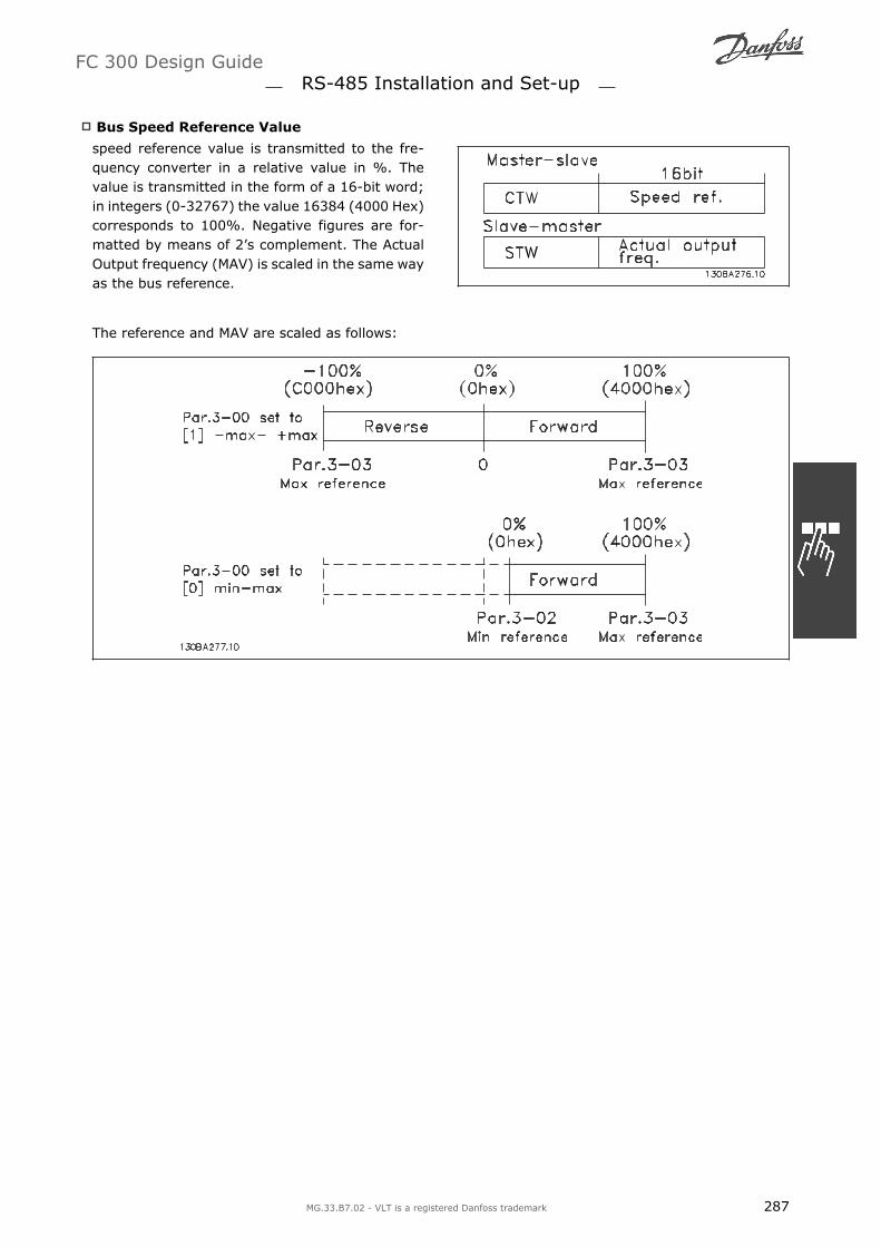
Bus Speed Reference Value
speed reference value is transmitted to the fre-quency converter in a relative value in %. Thevalue is transmitted in the form of a 16-bit word;in integers (0-32767) the value 16384 (4000 Hex)corresponds to 100%. Negative figures are for-matted by means of 2s complement. The ActualOutput frequency (MAV) is scaled in the same wayas the bus reference.
The reference and MAV are scaled as follows:
FC 300 Design Guide RS-485 Installation and Set-up
MG.33.B7.02 - VLT is a registered Danfoss trademark 287

PROFIdrive Control Profile
This section describes the functionality of the control word and status word in the PROFIdrive profile.Select this profile by setting par. 8-10 Control word profile to PROFIdrive.
Control Word according to PROFIdrive Profile (CTW)
The Control word is used to send commands froma master (e.g. a PC) to a slave.
Bit Bit = 0 Bit = 100 OFF 1 ON 101 OFF 2 ON 202 OFF 3 ON 303 Coasting No coasting04 Quick stop Ramp05 Hold frequency out-
putUse ramp
06 Ramp stop Start07 No function Reset08 Jog 1 OFF Jog 1 ON09 Jog 2 OFF Jog 2 ON10 Data invalid Data valid11 No function Slow down12 No function Catch up13 Parameter set-up Selection lsb14 Parameter set-up Selection msb15 No function Reverse
Explanation of the Control Bits
Bit 00, OFF 1/ON 1Normal ramp stop using the ramp times of the actual selected ramp.Bit 00 = "0" leads to the stop and activation of the output relay 1 or 2 if the output frequency is 0 Hz andif [Relay 123] has been selected in par. 5-40 Function relay.When bit 00 = "1", the frequency converter is in State 1: Switching on inhibited.Please refer to the PROFIdrive State Transition Diagram, at the end of this section.
Bit 01, OFF 2/ON 2Coasting stopWhen bit 01 = "0", a coasting stop and activation of the output relay 1 or 2 occurs if the output frequencyis 0 Hz and if [Relay 123] has been selected in par. 5-40 Function relay.When bit 01 = "1", the frequency converter is in State 1: Switching on inhibited. Please refer to thePROFIdrive State Transition Diagram, at the end of this section.
Bit 02, OFF 3/ON 3Quick stop using the ramp time of par. 3-81 Quick stop ramp time. When bit 02 = "0", a quick stop andactivation of the output relay 1 or 2 occurs if the output frequency is 0 Hz and if [Relay 123] has beenselected in par. 5-40 Function relay.When bit 02 = "1", the frequency converter is in State 1: Switching on inhibited.Please refer to the PROFIdrive State Transition Diagram, at the end of this section.
Bit 03, Coasting/No coastingCoasting stop Bit 03 = "0" leads to a stop. When bit 03 = "1", the frequency converter can start if theother start conditions are satisfied.
NB!The selection in par. 8-50 Coasting select determines how bit 03 is linked with the corre-sponding function of the digital inputs.
FC 300 Design Guide RS-485 Installation and Set-up
288 MG.33.B7.02 - VLT is a registered Danfoss trademark
Bit 04, Quick stop/RampQuick stop using the ramp time of par. 3-81 Quick stop ramp time.When bit 04 = "0", a quick stop occurs.When bit 04 = "1", the frequency converter can start if the other start conditions are satisfied.
NB!The selection in par. 8-51 Quick stop select determines how bit 04 is linked with the corre-sponding function of the digital inputs.
Bit 05, Hold frequency output/Use rampWhen bit 05 = "0", the current output frequency is being maintained even if the reference value is modi-fied.When bit 05 = "1", the frequency converter can perform its regulating function again; operation occursaccording to the respective reference value.
Bit 06, Ramp stop/StartNormal ramp stop using the ramp times of the actual ramp as selected. In addition, activation of theoutput relay 01 or 04 if the output frequency is 0 Hz if Relay 123 has been selected in par. 5-40 Functionrelay. Bit 06 = "0" leads to a stop. When bit 06 = "1", the frequency converter can start if the other startconditions are satisfied.
NB!The selection in par. 8-53 Start select determines how bit 06 is linked with the correspondingfunction of the digital inputs.
Bit 07, No function/ResetReset after switching off.Acknowledges event in fault buffer.When bit 07 = "0", no reset occurs.When there is a slope change of bit 07 to "1", a reset occurs after switching off.
Bit 08, Jog 1 OFF/ONActivation of the pre-programmed speed in par. 8-90 Bus Jog 1 speed. JOG 1 is only possible if bit 04 ="0" and bit 00 - 03 = "1".
Bit 09, Jog 2 OFF/ONActivation of the pre-programmed speed in par. 8-91 Bus Jog 2 speed. JOG 2 is only possible if bit 04 ="0" and bit 00 - 03 = "1".
Bit 10, Data invalid/validIs used to tell the frequency converter whether the control word is to be used or ignored. Bit 10 = 0causes the control word to be ignored, Bit 10 = 1 causes the control word to be used. This function isrelevant, because the control word is always contained in the telegram, regardless of which type of tele-gram is used, i.e. it is possible to turn off the control word if you do not wish to use it in connection withupdating or reading parameters.
Bit 11, No function/Slow downIs used to reduce the speed reference value by the amount given in par. 3-12 Catch up/slow down value.When bit 11 = "0", no modification of the reference value occurs. When bit 11 = "1", the reference valueis reduced.
Bit 12, No function/Catch upIs used to increase the speed reference value by the amount given in par. 3-12 Catch up/slow downvalue.When bit 12 = "0", no modification of the reference value occurs.When bit 12 = "1", the reference value is increased.If both - slowing down and accelerating - are activated (bit 11 and 12 = "1"), slowing down has priority,i.e. the speed reference value will be reduced.
FC 300 Design Guide RS-485 Installation and Set-up
MG.33.B7.02 - VLT is a registered Danfoss trademark 289

Bits 13/14, Set-up selectionBits 13 and 14 are used to choose between thefour parameter set-ups according to the followingtable:
The function is only possible if Multi Set-up hasbeen chosen in par. 0-10 Active set-up. The se-lection in par. 8-55 Set-up select determines howbits 13 and 14 are linked with the correspondingfunction of the digital inputs. Changing set-upwhile running is only possible if the set-ups havebeen linked in par. 0-12 This set-up linked to.
Set-up Bit 13 Bit 141 0 02 1 03 0 14 1 1
Bit 15, No function/ReverseBit 15 = 0 causes no reversing.Bit 15 = 1 causes reversing.Note: In the factory setting reversing is set to digital in par. 8-54 Reversing select.
NB!Bit 15 causes reversing only when Ser. communication, Logic or or Logic and is selected.
FC 300 Design Guide RS-485 Installation and Set-up
290 MG.33.B7.02 - VLT is a registered Danfoss trademark

Status Word according to PROFIdrive Profile(STW)
The Status word is used to notify a master (e.g. aPC) about the status of a slave.
Bit Bit = 0 Bit = 100 Control not
readyControl ready
01 Drive not ready Drive ready02 Coasting Enable03 No error Trip04 OFF 2 ON 205 OFF 3 ON 306 Start possible Start not possible07 No warning Warning08 Speed ≠ refer-
enceSpeed = reference
09 Local operation Bus control10 Out of frequency
limitFrequency limit ok
11 No operation In operation12 Drive OK Stopped, autostart13 Voltage OK Voltage exceeded14 Torque OK Torque exceeded15 Timer OK Timer exceeded
Explanation of the Status Bits
Bit 00, Control not ready/readyWhen bit 00 = "0", bit 00, 01 or 02 of the Control word is "0" (OFF 1, OFF 2 or OFF 3) - or the frequencyconverter is switched off (trip).When bit 00 = "1", the frequency converter control is ready, but there is not necessarily power supply tothe unit present (in the event of external 24 V supply of the control SYSTEM).
Bit 01, VLT not ready/readySame significance as bit 00, however, there is a supply of the power unit. The frequency converter isready when it receives the necessary start signals.
Bit 02, Coasting/EnableWhen bit 02 = "0", bit 00, 01 or 02 of the Control word is "0" (OFF 1, OFF 2 or OFF 3 or coasting) - orthe frequency converter is switched off (trip).When bit 02 = "1", bit 00, 01 or 02 of the Control word is "1"; the frequency converter has not tripped.
Bit 03, No error/TripWhen bit 03 = "0", no error condition of the frequency converter exists.When bit 03 = "1", the frequency converter has tripped and requires a reset signal before it can start.
Bit 04, ON 2/OFF 2When bit 01 of the Control word is "0", then bit 04 = "0".When bit 01 of the Control word is "1", then bit 04 = "1".
Bit 05, ON 3/OFF 3When bit 02 of the Control word is "0", then bit 05 = "0".When bit 02 of the Control word is "1", then bit 05 = "1".
FC 300 Design Guide RS-485 Installation and Set-up
MG.33.B7.02 - VLT is a registered Danfoss trademark 291

Bit 06, Start possible/Start not possibleIf PROFIdrive has been selected in par. 8-10 Control word profile, bit 06 will be "1" after a switch-offacknowledgement, after activation of OFF2 or OFF3, and after switching on the mains voltage. Start notpossible will be reset, with bit 00 of the Control word being set to "0" and bit 01, 02 and 10 being set to"1".
Bit 07, No warning/WarningBit 07 = 0 means that there are no warnings.Bit 07 = 1 means that a warning has occurred.
Bit 08, Speed ≠ reference / Speed = referenceWhen bit 08 = "0", the current speed of the motor deviates from the set speed reference value. This mayoccur, for example, when the speed is being changed during start/stop through ramp up/down.When bit 08 = "1", the current speed of the motor corresponds to the set speed reference value.
Bit 09, Local operation/Bus controlBit 09 = "0" indicates that the frequency converter has been stopped by means of the stop button on thecontrol panel, or that [Linked to hand] or [Local] has been selected in par. 3-13 Reference site.When bit 09 = "1", the frequency converter can be controlled through the serial interface.
Bit 10, Out of frequency limit/Frequency limit OKWhen bit 10 = "0", the output frequency is outside the limits set in par. 4-11 Motor speed low limit(rpm) and par. 4-13 Motor speed high limit (rpm). When bit 10 = "1", the output frequency is within theindicated limits.
Bit 11, No operation/OperationWhen bit 11 = "0", the motor does not turn.When bit 11 = "1", the frequency converter has a start signal, or the output frequency is higher than 0Hz.
Bit 12, Drive OK/Stopped, autostartWhen bit 12 = "0", there is no temporary overloading of the inverter.When bit 12 = "1", the inverter has stopped due to overloading. However, the frequency converter hasnot switched off (trip) and will start again after the overloading has ended.
Bit 13, Voltage OK/Voltage exceededWhen bit 13 = "0", the voltage limits of the frequency converter are not exceeded.When bit 13 = "1", the direct voltage in the intermediate circuit of the frequency converter is too low ortoo high.
Bit 14, Torque OK/Torque exceededWhen bit 14 = "0", the motor torque is below the limit selected in par. 4-16 Torque limit motor mode andpar. 4-17 Torque limit generator mode. When bit 14 = "1", the limit selected in par. 4-16 Torque limitmotor mode or par. 4-17 Torque limit generator mode is exceeded.
Bit 15, Timer OK/Timer exceededWhen bit 15 = "0", the timers for the thermal motor protection and thermal frequency converter protec-tion have not exceeded 100%.When bit 15 = "1", one of the timers has exceeded 100%.
FC 300 Design Guide RS-485 Installation and Set-up
292 MG.33.B7.02 - VLT is a registered Danfoss trademark
Troubleshooting
Warnings / Alarm Messages
A warning or an alarm is signalled by the relevant LED on the front of the frequency converter and indi-cated by a code on the display.
A warning remains active until its cause is no longer present. Under certain circumstances operation ofthe motor may still be continued. Warning messages may be critical, but are not necessarily so.
In the event of an alarm, the frequency converter will have tripped. Alarms must be reset to restartoperation once their cause has been rectified. This may be done in three ways:
1. By using the [RESET] control button on the LCP control panel.
2. Via a digital input with the Reset function.
3. Via serial communication/optional fieldbus.
NB!After a manual reset using the [RESET] button on the LCP, the [AUTO ON] button must bepressed to restart the motor.
If an alarm cannot be reset, the reason may be that its cause has not been rectified, or the alarm is trip-locked (see also table on following page).
Alarms that are trip-locked offer additional protection, meaning that the mains supply must be switchedoff before the alarm can be reset. After being switched back on, the FC 300 is no longer blocked and maybe reset as described above once the cause has been rectified.
Alarms that are not trip-locked can also be reset using the automatic reset function in parameters 14-20(Warning: automatic wake-up is possible!)
If a warning and alarm is marked against a code in the table on the following page, this means that eithera warning occurs before an alarm, or else that you can specify whether it is a warning or an alarm thatis to be displayed for a given fault.
This is possible, for instance, in parameters 1-90 Motor Thermal Protection. After an alarm or trip, themotor carries on coasting, and the alarm and warning flash on the FC 300. Once the problem has beenrectified, only the alarm continues flashing.
FC 300 Design Guide
MG.33.B7.02 - VLT is a registered Danfoss trademark 293

Alarm/Warning code listNo. Description Warning Alarm/Trip Alarm/Trip Lock Parameter Refer-
ence1 10 Volts low X 2 Live zero error (X) (X) 6-013 No motor (X) 1-804 Mains phase loss (X) (X) (X) 14-125 DC link voltage high X 6 DC link voltage low X7 DC over voltage X X 8 DC under voltage X X9 Inverter overloaded X X 10 Motor ETR over temperature (X) (X) 1-9011 Motor thermistor over temperature (X) (X) 1-9012 Torque limit X X13 Over Current X X X 14 Earth fault X X X15 Hardware mismatch X X 16 Short Circuit X X17 Control word timeout (X) (X) 8-0425 Brake resistor short-circuited X26 Brake resistor power limit (X) (X) 2-1327 Brake chopper short-circuited X X28 Brake check (X) (X) 2-1529 Power board over temp X X X30 Motor phase U missing (X) (X) (X) 4-5831 Motor phase V missing (X) (X) (X) 4-5832 Motor phase W missing (X) (X) (X) 4-5833 Inrush fault X X34 Fieldbus communication fault X X 38 Internal fault X X47 24 V supply low X X X 48 1.8 V supply low X X49 Speed limit X 50 AMA calibration failed X51 AMA check Unom and Inom X 52 AMA low Inom X53 AMA motor too big X 54 AMA motor too small X55 AMA parameter out of range X 56 AMA interrupted by user X57 AMA timeout X 58 AMA internal fault X X59 Current limit X 62 Output Frequency at Maximum Limit X63 Mechanical Brake Low (X) 2-2064 Voltage Limit X65 Control Board Over-temperature X X X 66 Heat sink Temperature Low X67 Option Configuration has Changed X 80 Drive Initialised to Default Value X90 Encoder Loss (X) (X) 17-61
(X) Dependent on parameterA trip is the action when an alarm has appeared.The trip will coast the motor and can be reset bypressing the reset bottom or make a reset by adigital input (Par. 5-1* [1]). The origin event thatcaused an alarm cannot damage the drive orcause dangerous conditions. A trip lock is an ac-tion when an alarm occurs, which may cause dam-age to drive or connected parts. A Trip Locksituation can only be reset by a power cycling.
LED indicationWarning yellowAlarm flashing red
Trip locked yellow and red
FC 300 Design Guide Troubleshooting
294 MG.33.B7.02 - VLT is a registered Danfoss trademark

Description of Alarm Word, Warning Word and extended Status WordAlarm Word Extended Status WordBit Hex Dec AlarmWord WarningWord ExtendedStatusWord0 00000001 1 Brake Check Brake Check Ramping1 00000002 2 Pwr. Card Temp Pwr. Card Temp AMA Running2 00000004 4 Earth Fault Earth Fault Start CW/CCW3 00000008 8 Ctrl.Card Temp Ctrl.Card Temp Slow Down4 00000010 16 Ctrl. Word TO Ctrl. Word TO Catch Up5 00000020 32 Over Current Over Current Feedback High6 00000040 64 Torque Limit Torque Limit Feedback Low7 00000080 128 Motor Th Over Motor Th Over Output Current High8 00000100 256 Motor ETR Over Motor ETR Over Output Current Low9 00000200 512 Inverter Overld. Inverter Overld. Output Freq High10 00000400 1024 DC under Volt DC under Volt Output Freq Low11 00000800 2048 DC over Volt DC over Volt Brake Check OK12 00001000 4096 Short Circuit DC Voltage Low Braking Max13 00002000 8192 Inrush Fault DC Voltage High Braking14 00004000 16384 Mains ph. Loss Mains ph. Loss Out of Speed Range15 00008000 32768 AMA Not OK No Motor OVC Active16 00010000 65536 Live Zero Error Live Zero Error 17 00020000 131072 Internal Fault 10V Low18 00040000 262144 Brake Overload Brake Overload 19 00080000 524288 U phase Loss Brake Resistor20 00100000 1048576 V phase Loss Brake IGBT 21 00200000 2097152 W phase Loss Speed Limit22 00400000 4194304 Fieldbus Fault Fieldbus Fault 23 00800000 8388608 24 V Supply Low 24V Supply Low24 01000000 16777216 Mains Failure Mains Failure 25 0200000 33554432 1.8V Supply Low Current Limit26 04000000 67108864 Brake Resistor Low Temp 27 08000000 134217728 Brake IGBT Voltage Limit28 10000000 268435456 Option Change Unused 29 20000000 536870912 Drive Initialised Unused30 40000000 1073741824 Safe Stop Unused31 80000000 2147483648 Mech. brake low Extended Status Word
The alarm words, warning words and extended status words can be read out via serial bus or optionalfieldbus for diagnose. See also par. 16-90, 16-92 and 16-94.
WARNING 110 Volts low:The 10 V voltage from terminal 50 on the controlcard is below 10 V.Remove some of the load from terminal 50, as the10 V supply is overloaded. Max. 15 mA or mini-mum 590 Ω.
WARNING/ALARM 2Live zero error:The signal on terminal 53 or 54 is less than 50%of the value set in par. 6-10, 6-12, 6-20, or 6-22respectively.
WARNING/ALARM 3No motor:No motor has been connected to the output of thefrequency converter.
WARNING/ALARM 4Mains phase loss:A phase is missing on the supply side, or themains voltage imbalance is too high.
This message also appears in case of a fault in theinput rectifier on the frequency converter.Check the supply voltage and supply currents tothe frequency converter.
WARNING 5DC link voltage high:The intermediate circuit voltage (DC) is higherthan the overvoltage limit of the control system.The frequency converter is still active.
WARNING 6DC link voltage lowThe intermediate circuit voltage (DC) is below theundervoltage limit of the control system. The fre-quency converter is still active.
WARNING/ALARM 7DC over voltage:If the intermediate circuit voltage exceeds thelimit, the frequency converter trips after a time.Possible corrections:
FC 300 Design Guide Troubleshooting
MG.33.B7.02 - VLT is a registered Danfoss trademark 295

Select Over Voltage Control function inpar. 2-17
Connect a brake resistor
Extend the ramp time
Activate functions in par. 2-10
Increase par. 14-26
Selecting OVC function will extend the ramptimes.
Alarm/warning limits:FC 300 Series 3 x 200-240 V
AC3 x 380-500 VAC
[VDC] [VDC]
Undervoltage 185 373Voltage warning low 205 410Voltage warninghigh (w/o brake - w/brake)
390/405 810/840
Overvoltage 410 855
The voltages stated are the intermediate circuit volt-age of the FC 300 with a tolerance of ± 5 %. Thecorresponding mains voltage is the intermediate cir-cuit voltage (DC-link) divided by 1.35
WARNING/ALARM 8DC under voltage:If the intermediate circuit voltage (DC) drops be-low the voltage warning low limit (see tableabove), the frequency converter checks if 24 Vbackup supply is connected.If no 24 V backup supply is connected, the fre-quency converter trips after a given time depend-ing on the unit.To check whether the supply voltage matches thefrequency converter, see General Specifications.
WARNING/ALARM 9Inverter overloaded:The frequency converter is about to cut out be-cause of an overload (too high current for toolong). The counter for electronic, thermal inverterprotection gives a warning at 98% and trips at100%, while giving an alarm. You cannot reset thefrequency converter until the counter is below90%.The fault is that the frequency converter is over-loaded by more than nominal current for too long.
WARNING/ALARM 10Motor ETR over temperature:According to the electronic thermal protection(ETR), the motor is too hot. You can choose if youwant the frequency converter to give a warning oran alarm when the counter reaches 100% in par.
1-90. The fault is that the motor is overloaded bymore than nominal current for too long. Checkthat the motor par. 1-24 is set correctly.
WARNING/ALARM 11Motor thermistor over temp:The thermistor or the thermistor connection is dis-connected. You can choose if you want the fre-quency converter to give a warning or an alarm inpar. 1-90. Check that the thermistor is connectedcorrectly between terminal 53 or 54 (analog volt-age input) and terminal 50 (+ 10 Volts supply), orbetween terminal 18 or 19 (digital input PNP only)and terminal 50. If a KTY sensor is used, checkfor correct connection between terminal 54 and55.
WARNING/ALARM 12Torque limit:The torque is higher than the value in par. 4-16(in motor operation) or the torque is higher thanthe value in par. 4-17 (in regenerative operation).
WARNING/ALARM 13Over Current:The inverter peak current limit (approx. 200% ofthe rated current) is exceeded. The warning willlast approx. 8-12 sec., then the frequency con-verter trips and issues an alarm. Turn off the fre-quency converter and check if the motor shaft canbe turned and if the motor size matches the fre-quency converter.
ALARM 14Earth fault:There is a discharge from the output phases toearth, either in the cable between the frequencyconverter and the motor or in the motor itself.Turn off the frequency converter and remove theearth fault.
ALARM 15In-complete hardware:A fitted option is not handled by the present con-trol board (hardware or software).
ALARM 16Short-circuit:There is short-circuiting in the motor or on themotor terminals.Turn off the frequency converter and remove theshort-circuit.
WARNING/ALARM 17Control word timeout:There is no communication to the frequency con-verter.
FC 300 Design Guide Troubleshooting
296 MG.33.B7.02 - VLT is a registered Danfoss trademark

The warning will only be active when par. 8-04 isNOT set to OFF.If par. 8-04 is set to Stop and Trip, a warning ap-pears and the frequency converter ramps down tozero speed, while giving an alarm.Par. 8-03 Control Word Timeout Time could pos-sibly be increased.
WARNING 25Brake resistor short-circuited:The brake resistor is monitored during operation.If it short-circuits, the brake function is discon-nected and the warning appears. The frequencyconverter still works, but without the brake func-tion. Turn off the frequency converter and replacethe brake resistor (see par. 2-15 Brake Check).
ALARM/WARNING 26Brake resistor power limit:The power transmitted to the brake resistor is cal-culated as a percentage, as a mean value over thelast 120 s, on the basis of the resistance value ofthe brake resistor (par. 2-11) and the intermedi-ate circuit voltage. The warning is active when thedissipated braking power is higher than 90%. IfTrip [2] has been selected in par. 2-13, the fre-quency converter cuts out and issues this alarm,when the dissipated braking power is higher than100%.
WARNING/ALARM 27Brake chopper fault:The brake transistor is monitored during opera-tion and if it short-circuits, the brake function dis-connects and the warning comes up. The frequen-cy converter is still able to run, but since the braketransistor has short-circuited, substantial power istransmitted to the brake resistor, even if it is in-active.Turn off the frequency converter and remove thebrake resistor.
Warning: There is a risk of substantialpower being transmitted to the brakeresistor if the brake transistor is short-circuited.
ALARM/WARNING 28Brake check failed:Brake resistor fault: the brake resistor is not con-nected/working.
WARNING/ALARM 29Drive over temperature:If the enclosure is IP 20 or IP 21/TYPE 1, the cut-
out temperature of the heat-sink is 95 oC +5 oC.
The temperature fault cannot be reset, until the
temperature of the heatsink is below 70 oC.The fault could be:
- Ambient temperature too high
- Too long motor cable
ALARM 30Motor phase U missing:Motor phase U between the frequency converterand the motor is missing.Turn off the frequency converter and check motorphase U.
ALARM 31Motor phase V missing:Motor phase V between the frequency converterand the motor is missing.Turn off the frequency converter and check motorphase V.
ALARM 32Motor phase W missing:Motor phase W between the frequency converterand the motor is missing.Turn off the frequency converter and check motorphase W.
ALARM 33Inrush fault:Too many powerups have occured within a shorttime period. See the chapter General Specifica-tions for the allowed number of powerups withinone minute.
WARNING/ALARM 34Fieldbus communication fault:The fieldbus on the communication option cardis not working.
ALARM 38Internal fault:By this alarm it may be necessary to contact yourDanfoss supplier. Some typical alarm messages:0 - The serial port cannot be initialized. Serioushardware failure256 - The power E2PROM data is defect or too old512 - The control board E2PROM data is defect ortoo old513 - Communication time out Reading E2PROMdata514 - Communication time out Reading E2PROMdata515 - The Application Orientated Control cannotrecognize the E^2 Prom data
FC 300 Design Guide Troubleshooting
MG.33.B7.02 - VLT is a registered Danfoss trademark 297
516 - Cannot write write to the E^2 PROM be-cause a write command is on progress517 - The write command is under time out 518 Failure in the E^2 Prom519 - Missing or invalid BarCode data in E^2Prom1024 1279 CAN telegram cannot be sent. (1027indicate a possible hardware failure)1281 - Digital Signal Processor flash time-out1282 - Power micro software version mismatch1283 - Power E^2PROM data version mismatch1284 - Cannot read Digital Signal Processor soft-ware version1299 - OptionSW in slot A is too old1300 - OptionSW in slot B is too old1301 - OptionSW in slot C0 is too old1302 - OptionSW in slot C1 is too old1315 - Option SW in slot A is not supported (notallowed)1316 - Option SW in slot B is not supported (notallowed)1317 - Option SW in slot C0 is not supported (notallowed)1318 - Option SW in slot C1 is not supported (notallowed)1536 - An exception in the Application OrientatedControl is registered. Debug information written inLCP1792 - DSP watchdog is active. Debugging ofpower part data Motor Orientated Control data nottransferred correctly2049 - Power data restarted2315 - Missing SW version from power unit.2816 - Stack overflow Control board module2817 - Scheduler slow tasks2818 - Fast tasks2819 - Parameter thread2820 - LCP stack overflow2821 - Serial port overflow2822 - USB port overflow3072 - 5122 Parameter value is outside its limits.Perform a initialization. Parameter number caus-ing the alarm: Subtract the code from 3072. ExError code 3238: 3238-3072 = 166 is outside thelimit..5123 - Option in slot A: Hardware incompatiblewith Control board hardware.5124 - Option in slot B: Hardware incompatiblewith Control board hardware5125 - Option in slot C0: Hardware incompatiblewith Control board hardware5126 - Option in slot C1: Hardware incompatiblewith Control board hardware
5376 - 5631 Out of memory
WARNING 4724 V supply low:The external 24 V DC backup power supply maybe overloaded, otherwise contact your Danfosssupplier.
ALARM 481.8 V supply low:Contact your Danfoss supplier.
WARNING 49Speed limit:The speed has been limited by range in par. 4-11and par. 4-13.
ALARM 50AMA calibration failed:Contact your Danfoss supplier.
ALARM 51AMA check Unom and Inom:The setting of motor voltage, motor current, andmotor power is presumably wrong. Check the set-tings.
ALARM 52AMA low Inom:The motor current is too low. Check the settings.
ALARM 53AMA motor too big:The motor is too big for the AMA to be carried out.
ALARM 54AMA motor too small:The motor is too small for the AMA to be carriedout.
ALARM 55AMA par. out of range:The par. values found from the motor are outsideacceptable range.
ALARM 56AMA interrupted by user:The AMA has been interrupted by the user.
ALARM 57AMA timeout:Try to start the AMA once again, until the AMA iscarried out. Please note that repeated runs mayheat the motor to a level where the resistance Rsand Rr are increased.
WARNING/ALARM 58AMA internal fault:Contact your Danfoss supplier.
FC 300 Design Guide Troubleshooting
298 MG.33.B7.02 - VLT is a registered Danfoss trademark

WARNING 59Current limit:The current is higher than the value in par. 4-18.
WARNING 62Output Frequency at Maximum Limit:The output frequency is limited by the value set inpar. 4-19
ALARM 63Mechanical Brake Low:The actual motor current has not exceeded therelease brake current within the Start delaytime window.
WARNING 64Voltage Limit:The load and speed combination demands a motorvoltage higher than the actual DC link voltage.
WARNING/ALARM/TRIP 65Control Card Over Temperature:Control card over temperature: The cut-out tem-perature of the control card is 80° C.
WARNING 66Heatsink Temperature Low:The heat sink temperature is measured as 0° C.This could indicate that the temperature sensor isdefective and thus the fan speed is increased tothe maximum in case the power part or controlcard is very hot.
ALARM 67Option Configuration has Changed:One or more options has either been added or re-moved since the last power-down.
ALARM 70Illegal Frequency Configuration:Actual combination of control board and powerboard is illegal.
ALARM 80Drive Initialised to Default Value:Parameter settings are initialised to default set-ting after a manual (three-finger) reset or via par.14-22.
FC 300 Design Guide Troubleshooting
MG.33.B7.02 - VLT is a registered Danfoss trademark 299

Index
224 V Encoder 132
AAbbreviations 1
Access To Control Terminals 2
Access To Quick Menu W/o Password 131
Accessory Bag 2
Acoustic Noise 1
Active Set-up 123
Aggressive Environments 1
Air Humidity 1
Alarm Messages 293
Alarm Word 190
Ama 104
Analog Input 8
Analog Inputs 8
Analog Inputs 55
Analog Output 56
Automatic Motor Adaptation 104
Automatic Motor Adaptation (ama) 88
Automatic Motor Adaptation (ama) 134
BBack Emf At 1000 Rpm 137
Basic Wiring Example 2
Baud Rate 120
Brake Check 147
Brake Connection Option 90
Brake Current 149
Brake Function 42
Brake Power 147
Brake Power 147
Brake Power 9
Brake Power 42
Brake Power Monitoring 147
Brake Resistor 1
Brake Resistors 271
Braking Time 283
Break-away Torque 8
Bus Jog 2 Speed 193
CCable Clamp 98
Cable Clamps 95
Cable Lengths And Cross Sections 53
Catch Up 167
Catch Up / Slow Down 22
Catch Up/slow Down Value 151
Changing A Group Of Numeric Data Values 3
Changing A Text Value 3
Changing Data 3
Changing Of Data Value 3
Clockwise 160
Clockwise 176
Clockwise 237
Clockwise 140
Clockwise 141
Clockwise Rotation 93
Coast 140
Coasting 7
Coasting 109
Coasting 191
Coasting 283
Coasting 285
Communication Option 297
Configuration Mode 132
Connection To Mains 2
Control Cables 2
Control Cables 86
Control Cables 95
Control Card Performance 57
Control Card, +10 V Dc Output 57
Control Card, 24 V Dc Output 56
Control Card, Rs 485 Serial Communication 56
Control Card, Usb Serial Communication 58
Control Characteristics 57
Control Terminals 2
Control Terminals 2
Control Word 282
Control Word According To Profidrive Profile(ctw) 288
FC 300 Design Guide
300 MG.33.B7.02 - VLT is a registered Danfoss trademark

Control Word Timeout Function 188
Cooling 60
Cooling 143
Cooling Conditions 74
Counter Clockwise 160
Current Lim Cont, Proportional Gain 221
DD-axis Inductance (ld) 136
Dc Brake 146
Dc Brake 140
Dc Brake 191
Dc Brake 283
Dc Braking Time 146
Dc Hold 146
Dc Hold 140
Dc Hold 140
Dc Hold 141
Dc Link 295
Dc Link Voltage 231
Dead Band 24
Dead Band Around Zero 1
Decoupling Plate 79
Default Settings 3
Default Settings 239
Definitions 1
Derating For Low Air Pressure 60
Derating For Running At Low Speed 60
Devicenet 5
Devicenet 65
Digital Inputs: 54
Digital Output 56
Direction Of Motor Rotation 93
Display Line 2 Large 127
Display Mode 2
Display Mode - Selection Of Read-outs 3
Disposal Instruction 1
Drive Configurator 2
EEarth Leakage Current 1
Earth Leakage Current 95
Earthing 98
Earthing Of Screened/armoured Control Ca-bles 98
Efficiency 1
Electrical Installation 2
Electrical Installation 2
Electrical Installation 86
Electrical Installation - Emc Precautions 95
Electrical Terminals 85
Electro-mechanical Brake 103
Electronic Terminal Relay 144
Emc Test Results 37
Encoder Feedback 17
Encoder Positive Direction 237
Encoder Pulses 176
Encoder Signal Monitoring 238
End-of-timeout Function 189
Equalising Cable, 98
Etr 92
Etr 143
Etr 230
Etr 296
Ext. Status Word 235
External 24 V Dc Supply 270
External Reference 232
Extreme Running Conditions 44
FFault Log: Error Code 226
Fault Log: Time 226
Fault Log: Value 226
Fc Profile 282
Flux 1
Flux 1
Flying Start 141
Freeze Output 7
Freeze Reference 22
Freq. Input #29 [hz] 233
Freq. Input #33 [hz] 233
Frequency 230
Function At Stop 141
Fuses 2
GGalvanic Isolation (pelv) 39
General Warning 6
Graphical Display 107
FC 300 Design Guide Index
MG.33.B7.02 - VLT is a registered Danfoss trademark 301

HHarmonic Filters 68
Heatsink Temp. 231
High Voltage Test 95
Hold Output Frequency 283
IIncremental Encoder 232
Indexed Parameters 3
Indicator Lights 108
Infinitely Variable Change Of Numeric DataValue 3
Initialisation 3
Intermediate Circuit 42
Intermediate Circuit 45
Intermediate Circuit 58
Intermediate Circuit 59
Intermediate Circuit 90
Intermediate Circuit 295
Internal Current Control In Vvc+ Mode 1
Iron Loss Resistance (rfe) 136
It Mains 221
JJog 284
Jog 7
Jog Ramp Time 158
Jog Speed 151
Jog Speed 153
KKty Sensor 296
Kwh Counter 223
LLanguage 122
Lc Filter 80
Lc Filter 272
Lc Filters 3
Lcp 7
Lcp 9
Lcp 21
Lcp 110
Lcp 118
Lcp 271
Lcp 102 107
Lcp Copy 130
Lcp Id No 227
Leakage Current 40
Leds 107
Load Sharing 90
Load Type 140
Local (hand On) And Remote (auto On)Control 1
Local Control Keys 3
Local Control Panel 2
Local Reference 123
MMain Menu 112
Main Menu Mode 3
Main Menu Mode 109
Main Reactance 134
Main Reactance (xh) 136
Mains Failure 218
Mains Rfi Filter Circuit 221
Mains Supply 49
Mains Supply 49
Mains Supply 52
Mains Supply 52
Mains Supply 10
Mains Supply (l1, L2, L3) 53
Mains Supply Interference 99
Mains Voltage At Mains Fault 218
Max Output Frequency 161
Maximum Inertia 140
Maximum Limit 159
Maximum Reference 151
Mechanical Brake 1
Mechanical Dimensions 71
Mechanical Dimensions 72
Mechanical Mounting 74
Min Speed For Function At Stop [hz] 142
Min Speed For Function At Stop [rpm] 142
Minimum Inertia 140
Minimum Limit 159
Missing Motor Phase Function 163
Moment Of Inertia 45
Motor Angle Offset 137
FC 300 Design Guide Index
302 MG.33.B7.02 - VLT is a registered Danfoss trademark

Motor Cables 2
Motor Cables 95
Motor Connection 2
Motor Cont. Rated Torque 134
Motor Current 134
Motor Feedback 1
Motor Feedback 132
Motor Frequency 134
Motor Name Plate 88
Motor Nominal Speed 134
Motor Output 53
Motor Parameters 104
Motor Phases 44
Motor Poles 136
Motor Power [hp] 134
Motor Power [kw] 133
Motor Protection 53
Motor Protection 92
Motor Protection 143
Motor Rotation 93
Motor Speed Unit 122
Motor Thermal Protection 45
Motor Thermal Protection 2
Motor Thermal Protection 143
Motor Thermal Protection 286
Motor Voltage 134
Motor Voltage 229
Motor Voltage 59
NName Plate Data 88
Name Plate Data 88
Non Ul Compliance 81
Normal Torque 133
Numerical Local Control Panel 3
OOperating Hours 223
Operating Mode 123
Operating State At Power-up (hand) 123
Operation Mode 219
Ordering Form Type Code 2
Ordering Numbers 63
Ordering Numbers: Brake Resistors 65
Ordering Numbers: Harmonic Filters 68
Ordering Numbers: Lc Filter Modules 68
Ordering Numbers: Options And Accesso-ries 65
Output Performance (u, V, W) 53
Output Speed 141
Over-voltage Control 148
PParameter Selection 3
Parameter Set-up 3
Passive Load 140
Peak Voltage 1
Plc 98
Potentiometer Reference 2
Power Restore 159
Power Up's 223
Precise Stop 142
Precise Stop Counter 233
Precise Stop Function 142
Pre-magnetizing 141
Preset Reference 151
Preset Reference Select 192
Process Pid Control 1
Profibus 5
Profibus 65
Profibus Warning Word 196
Programming Of Torque Limit And Stop 2
Proportionalgain 184
Protection 15
Protection 39
Protection 40
Protection 81
Protection And Features 53
Pulse Reference 232
Pulse Start/stop 2
Pulse/encoder Inputs 55
QQuick Menu 109
Quick Menu 109
Quick Menu 3
Quick Menu Mode 109
Quick Menu Mode 112
Quick Menu Password 131
Quick Stop Ramp Time 158
FC 300 Design Guide Index
MG.33.B7.02 - VLT is a registered Danfoss trademark 303

Quick Stop Select 191
Quick Transfer Of Parameter Settings 2
RRamp 1 Ramp Down Time 154
Ramp 1 Ramp Up Time 154
Ramp 1 Type 154
Ramp 2 Ramp Down Time 155
Ramp 3 Ramp Down Time 156
Ramp 3 Ramp Up Time 156
Ramp 4 Ramp Down Time 157
Ramp Delay 159
Ramp Time 159
Rated Motor Speed 7
Rcd 10
Rcd 40
Reference Handling 1
Reference Source 1 152
Regional Settings 123
Relative Scaling Reference Source 153
Relay Connection 2
Relay Outputs 56
Relay Outputs 170
Removal Of Knockouts For Extra Cables 2
Reset 110
Reset Control Word Timeout 189
Reset Kwh Counter 223
Reset Mode 219
Reset] Key On Lcp 130
Residual Current Device 40
Rise Time 59
Rotor Leakage Reactance (x2) 136
Rotor Resistance (rr) 135
Rs-485 273
SSafe Stop 1
Safety Earth Connection 95
Scaling Of References And Feedback 1
Screened/armoured 86
Serial Communication 8
Serial Communication 58
Serial Communication 98
Side-by-side Installation 74
Smart Logic Control 43
Software Versions 65
Speed Pid 17
Speed Pid 18
Speed Pid Control 1
Speed Pid Feed Forward Factor 185
Speed Pid Lowpass Filter Time 185
Start Delay 140
Start Delay 140
Start Function 140
Start Function 140
Start Speed [hz] 141
Start Speed [rpm] 141
Start/stop 2
Stator Leakage Reactance 134
Stator Leakage Reactance (x1) 135
Stator Resistance (rs) 135
Status 108
Status Messages 107
Status Word 285
Status Word According To Profidrive Profile(stw) 291
Step Size 159
Step-by-step 3
Surroundings 57
Switches S201, S202, And S801 2
Switching Frequency 217
TTemperature-dependent Switch Frequency 61
Term 32/33 Encoder Direction 176
Term. 29 Low Frequency 174
Terminal 53 High Current 179
Terminal 53 Low Current 179
Terminal 54 High Current 179
Terminal 54 Low Current 179
Thermal Load 137
Thermal Load 230
Thermistor 10
Thermistor 143
Torque Characteristics 53
Torque Control 17
Torque Limit Generator Mode 161
Trip Delay At Torque Limit 220
FC 300 Design Guide Index
304 MG.33.B7.02 - VLT is a registered Danfoss trademark

UUsb Connection 83
Usb Connection 83
Use Of Emc-correct Cables 97
VVariable Torque 133
Vibration And Shock 1
Voltage Level 54
Vvcplus 10
Vvcplus 1
Vvcplus 132
WWarning Word 234
Warning Word 2 234
Warnings 293
FC 300 Design Guide Index
MG.33.B7.02 - VLT is a registered Danfoss trademark 305