contents 1 scope and general introduction 3 2 surface preparation · pdf file1 scope and...
TRANSCRIPT

1

2
CONTENTS
SR. NO. DESCRIPTION PAGE NO.
1 Scope and General Introduction 3
2 Surface Preparation Methods 4
3 Paint Application 5
4 Inspection and Testing of Paint Material 6
5 Frequency of Painting and Guarantee 8
6 Paint Monitoring System 9
7 Area classification & recommended painting schemes 9
8 Detailed Paint Specifications 21
9 Building Paints 33
10 Standard For Color Coding of Pipelines and Equipment. 34
11 Standard For Color Coding of Storage Tanks 42
12 Painting System for Tanks 43
13 Painting System for Crude oil storage Tanks. 55
14 Annexure – A (Crude tank painting specification) 63
15 Annexure – B (Crude tank paint performance guarantee requirements) 69
16 Annexure – C (Guarantee components) 70
17 Annexure – D ( Proforma of bank guarantee) 71
18 Annexure – E (Format of Indemnity bond) 74
19 Annexure – F (Procedure for measurement of DFT) 78
20 Annexure – G (Specification for TSAC) 83
21 Annexure - H (Sketches of Tanks Internal Painting) 94
22 Annexure – I (Brand names of paints) 96

3
1.0 SCOPE AND GENERAL INTRODUCTION This specification is applicable to general requirements of painting / coating within BPCL, Mumbai Refinery. These requirements must be fulfilled and complied for painting and coating of all equipment, pipelines, and storage tanks when they are off stream /shutdown and new fabrication. However on specific situational based recommendation from area inspection engineer, painting may be carried out with certain cautious deviations from these requirements such as painting without stipulated surface preparation. Painting includes surface preparation, clean up and application of painting. As a part of the periodical review of the specification, it has been reviewed the existing practices vis-a vis current industrial practices and available products with reputed painting manufacturers for enhancing effectiveness and durability of the painting systems. Accordingly, revised painting specification has been prepared for implementation at BPCL – Mumbai Refinery. Scope of work covered in this specification shall include, but not limited to the following:
Surface preparation
Selection and application of painting on:
a) Equipment including high temperature surfaces. b) Piping c) Steel Structures, buildings. d) Storage Tanks e) High temperature surfaces (Furnace casings, Stacks etc.).
1.1 Codes and standards
Following relevant international standards were considered.
SURFACE PREPARATION STANDARDS
a. Swedish Standards b. Steel Structures Painting Council (SSPC) c. NACE Standards d. ISO 4624, ISO 2802
The contractor shall arrange, at his own cost, to keep a set of latest edition of all the reference standards and codes at work site. The paint manufacturer’s instructions shall be followed as far as practicable at all times. Particular attention shall be paid to the following: a) Instructions for storage (Shelf life) b) Surface preparation prior to painting c) Mixing and thinning d) Application of paints and recommended limit on time intervals between coats

4
2. 0 SURFACE PREPARATION METHODS
Most metallic articles that are usually given protective coatings are heavily contaminated and require, at least, some cleaning treatment before the coating is applied. The importance of surface preparation cannot be over emphasized as many investigations have shown convincingly that the performance and durability of any protective coatings are, to a large extent governed by the thoroughness of surface preparation. Often they concluded that careful cleaning and preparation of the surface were more important than the quality of the protective coating.
Surface contamination in the form of rust, scale, oil grease and dirt must be removed before painting. Invisible contamination may also be present and represents, on the whole, a greater hazard. Examples of the latter are soldering fluxes, perspiration in the form of hand marks, chlorides from marine atmosphere and sulfite from industrial atmosphere. The following table-1 gives surface preparation specification in the descending order.
TABLE – 1: Surface Preparation in Descending Order of Effectiveness
Sl. No. Methods of cleaning Specifications NACE/SSPC/SIS-05-5900
1. White metal blast NACE # 1, SSPC SP 5-63,SA-3
2. Near –white metal blast NACE # 2, SSPC SP 10-63,SA-2.5
4. Acid Pickling SSPC SP 8-63,
5. Brush Blast NACE # 4, SSPC SP 7-63,SA-1
6. Flame Clean and Power Sanding SSPC SP 4-63
7. Power Tool Cleaning SSPC SP 3-63
8. Chip and Hand Wire Brush SSPC SP 2-63
9. Solvent Wipe SSPC SP 1-63
Note: (Sand blasting is not allowed in Refinery and MOT; hence Cu slag shall be used in all such cases except crude oil tanks internals) CU slag grading: a. 0.2 to 2.4 mm - coarse sieve for paint & rust removal.
b. 0.4 to 1.5 mm – for general new surfaces.
Cu slag is specified as a standard blasting material for BPCL-MR, as this will not create spark on metal surface while blasting. Cu slag is not reusable, resulting in less / negligible surface contamination.
2.1 Inspection of blasted steel surface
For the purpose of inspecting the blasted steel surface with cu slag abrasive, the respective “Visual standards” can be utilized.

5
White metal blast (SSPC 5-63, NACE No.1, and SA-3) This is defined as removing all rust, scale, paint etc. to a clean white metal which has a uniform Grey white appearance. Streaks and stains of rust or other contaminants are not allowed.
Near white metal (SSPC 10-63, NACE No.2, SA – 2.5)
This provides a surface of about 95% as clean as white metal. Light shades and streaks are not allowed.
Commercial blast (SSPC 6-63, NACE No.3, SA –2)
This type of blast is more difficult to describe. It essentially amounts to about 2/3 of a white metal blast, which allows for very slight residues of rust and paint in the form of staining.
Brush of blast (SSPC 7-63, NACE No.4 SA-1)
This preparation calls for removal of loose rust, paint, scales, etc. Tightly adherent paint, rust and scale is permitted to remain.
2.2 Pictorial Standards of different surface preparation to be adopted
During surface preparation operations, the surface condition obtained has to be compared with pictorial standards available for getting the specified condition.
3. 0 PAINT APPLICATION
The purpose of painting/coating application is to develop a continuous highly adherent film with an even thickness over the substrate. To achieve this, various factors have to be considered such as type of coatings and weather conditions, application methods etc
APPLICATION RESTRICTIONS
For all cases, paint manufacturer guidelines shall be followed. Following restrictions are given as recommended practices:
1. Coating application shall not be permitted during fog, mist or rain.
2. Coating application shall not be permitted when the relative humidity is 85 percent or above.
3. Coating application shall not be permitted when the steel surface temperature and/or
ambient temperature is below 10°C (50°F) .

6
4. Coating application shall not be permitted when the steel surface temperature and/or
ambient temperature is above 50°C (120°F).
5. Coating application shall not be permitted when the steel surface temperature is less than 3°C (5°F) above the dew point.
6. Humidity and dew point readings shall be taken by contractor with a sling Psychrometric
meter and calculated using psychrometric tables. Readings shall be taken prior to coating operations commencing and at least every four hours while coating application is ongoing.
7. Coatings shall not be applied before the surface has been inspected and the preparatory
work approved.
8. All sharp projections shall be ground to min. 2 mm radius and a thick stripe coat shall be applied at sharp edges.
9. Fresh water blasting or fresh water mopping shall be carried out on Salt water spray areas
before application of primer to remove the salts deposited on metal surface. Mopping can be repeated before application of other coats to remove salts deposited on previous coats, if such deposits are suspected. The permissible Chloride content for water used shall be 50 ppm maximum.
4.0 INSPECTION AND TESTING OF PAINTING MATERIAL
1) Painting Contractor shall procure from approved manufacturers as given below:
Akzo Nobel paints
Asian Paints PPG Ltd
Berger paints Ltd
CDC Carboline Ltd
Goodlass Nerolac Paints Ltd
Growel India (old - Bombay Paints)
Hempel paints
Jotun coatings
Kirloskar corrocoats
PPG Ind USA ( Sigma Coatings & Amercoat )
Shalimar paints Ltd.
Additional manufacturers may be approved by BPCL Inspection, subjecting to technical evaluation. All the procured paint material along with batch/test certificates shall be offered for BPCL inspection for approval. Remaining Shelf life shall be at least 90% of the total duration at the inspection above.

7
2) All paint materials shall be accompanied by Manufacturer Test Certificate. All zinc based paints shall have minimum 85% of metallic Zinc by weight of total solids on dry film. Glass flake epoxies shall have minimum 20% of glass flake pigments in dry film by weight of total pigments.
3) Inspection Engineer at his discretion may test paint formulations, if required.
4) Minimum suggested stages of inspection shall be:
a. Surface Preparation b. Primer application c. Each coat of paint
5) All defects noticed during stages of inspection, shall be rectified free of cost by the
contractor. All records shall be kept by the contractor.
6) To avoid rework it is preferable to take wet film thickness measurements during painting in order to ascertain the adequacy and uniformity of thickness.
7) Dry film thickness shall be taken on each coat after drying and curing of the coat. Dry
film thickness (DFT) readings shall be taken using a non-destructive dry film thickness instrument capable of storing the readings. Sufficient readings shall be taken covering each coat prior to application of the following coat to ensure the correct required DFT. The DFT indicated against each system shall be obtained by applying one or more coat of the paint based on paint properties. The Contractor is responsible to obtain the indicated DFT as per painting system specification.
8) DFT meter used shall be calibrated before each inspection and shall be witnessed by
the Inspector. It is the duty of the Inspector to satisfy him/herself with the performance of the DFT meter.
9) Frequency of inspection and criteria for acceptance of painting work shall be in
accordance with the following table - 2:
TABLE – 2:
Test Standard Frequency Acceptance criteria
Surface cleanliness
ISO 8501-1 One per ten (10) square meters
Sa 2 ½
Surface Profile ISO 8503-2 One per ten (10) square meters
As per coating procedure / data sheet
Total Soluble salt contamination
ISO 8502-9
One per twenty (20) square meters or minimum 5 tests whichever is more.
<5g/cm2

8
Dust ISO 8502-3 One per ten (10) square meters
Rating 2 or better
Adhesion ISO 4624 One pretest panel, per shift
5 MPa
Holiday Detection
NACE RP0188 100% of surface Zero defects
Dry Film Thickness
SSPC PA-2 As per Annexure – F Shall not be less than 80 % and more than 120 % of Specified dry film thickness (DFT).
Wet Film Thickness
ISO 2802 One per ten (10) square meters
Consistent with providing required DFT
10) Each contractor shall deploy adequate number of NACE CIP Level 1 qualified coating inspectors to monitor and inspect the surface preparation, storage, handling, mixing and application on substrate of the painting/coating and to ensure the compliance of this specification. The Inspection test plan which will be mandatory part of the contract shall be prepared by the above qualified inspector and get approved by BPCL. The CONTRACTOR’s qualified coating inspector and BPCL shall sign an inspection report as per approved inspection test plan. The report shall consist, as a minimum, of the following in addition to the inspection parameters and acceptable criteria as above table - 2.
Names of the APPLICATOR and the responsible personnel.
Dates when work was carried out.
Equipment and techniques used.
Type and calibration of instruments used.
Weather and ambient conditions.
11) Each contractor shall possess relevant standards and deploy all inspection tool/instrument to carry out the all above inspection and testing as per relevant standard.
12) For coating different color shades to be used for primer and intermediate coats, for ease in monitoring & identification of number of coats.
5.0 FREQUENCY & GUARANTEE Painting system frequency & guarantee except crude oil tank shall be AS follows:
a. For surfaces painted after Blasting as surface preparation 5 years
b. For surfaces painted after Manual Cleaning as surface preparation 4 years

9
c. For area within 100 m radius of Sea water cooling tower area (salt water spray area), 3
years.
d. Guarantee period shall be same as frequency.
e. Paint material shall be procured from approved manufacturers who also will stand
guarantee as above clause.
f. For all internal lining / painting works, manufacturer’s laboratory test statement /
Laboratory Paint performance certificates to be checked for specified services at design /
operating conditions. Material shall be procured from only those approved manufacturers
who will meet the above stated criteria.
g. For crude oil tanks frequency and guarantee shall be as per point no. 13
6.0 PAINT MONITORING SYSTEM
All painting works shall be mentioned (sign writing) with date of completion and PO no. at site/structure. These would facilitate defects observations and would also be basis for evaluation of the painting contractor /paint system and manufacturer for future works.
7. 0 AREA CLASSIFICATION & RECOMMENDED PAINTING SCHEMES
A) PAINTING SYSTEMS USING Cu-SLAG BLASTING TO Sa 2.5 (Min. Profile 50 microns) AS
SURFACE PREPARATION
SYSTEM – 1:
FOR EXTERNAL SURFACE OF VESSEL, EQUIPMENT / COLOUMN / PIPING, & ALL STRUCTURAL UP TO 100 0C TEMP.
(All areas in refinery including , Pipe Track No 14 , Pipe Track No. 9, SRU, ARU, CRU, FCCU (MEROX), CCU (Gas Treater), Pipe Track No. 7, CDU-VDU, HGU, Hydro Cracker, DHDS, New SRU, LOBS, DM Water Plant, Area, Pipe Track No. 4 & 5 (Along Road No. 4 Up To Road No. 5 & Along Road No. 5 Up to Road No. 6), MINAS, SWPH, FLARE, JETTY, Jawahar Island & Acid/Caustic Tanks).
Paint Type
Generic name of the paint DFT (Microns)
Method of Application
P1 Inorganic Zinc Ethyl Silicate Primer 1 x65 Air Spray / Airless
F1 High build two pack polyamide cured epoxy
2 x 100 Spray / Brush
U1 Aliphatic acrylic modified high solids weather resistant recoatable two pack polyurethane (finish coat)
1 x 40 Spray /
Roller/Brush
Total DFT 305

10
SYSTEM- 2:
OLD SEA WATER COOLING TOWER/RMP CT AROUND COOLING TOWER OF 100 M RADIUS (SALT WATER SPRAY AREA)
Paint Type
Generic name of the paint DFT (Microns)
Method of Application
P1 Inorganic Zinc Ethyl Silicate Primer 1 x 65 Air Spray / Airless
F2
Low VOC (Volatile Organic Compounds) two component internally flexibilised high build surface tolerant epoxy pigmented with Aluminium & Lamellar Micaceous Iron oxide coating
2 x 120 Spray/Brush
U1
Aliphatic acrylic modified high solids weather resistant recoatable two pack polyurethane (finish coat)
1 x 40 Spray/Roller/
Brush
Total DFT 345
Note: Salt water spray areas will require fresh water blasting or fresh water (Max. Chloride content 50 ppm) mopping shall be carried out on Salt Water spray areas, before application of primer, to remove the salts deposited on metal surface. Mopping can be repeated before application of other coats to remove salts deposited on previous coats, if such deposits are suspected.
SYSTEM-3:
FOR INSULATED EQUIPMENTS/VESSELS/COLUMNS/PIPELINES UPTO 200 0C TEMP.
Paint Type
Generic name of the paint DFT (Microns)
Method of Application
T8
Two component high solid High temperature (up to 200deg c dry heat) Phenolic CUI (corrosion under insulation) epoxy coating.
2 x 125
Spray /Brush
Total DFT 250

11
SYSTEM-4:
FOR INSULATED NON-CRITICAL EQUIPMENT AND PIPELINES FROM 200 0C TO 400 0 C TEMP.
SYSTEM - 5:
FOR INSULATED NON-CRITICAL EQUIPMENT AND PIPELINES FROM 400 0C TO 540 0 C TEMP.
SYSTEM – 6: FOR INSULATED CRITICAL EQUIPMENT (CARBON STEEL, LTCS, LOW ALLOY STEEL) LIKE VESSELS/RACTORS/COLUMNS/ EQUIPMENTS 200 0C TO 540 0 C TEMP.
Paint Type
Generic name of the paint DFT (Microns)
Method of Application
P1 Inorganic Zinc Ethyl Silicate Primer 1 x 65 Air Spray / Airless
AND
T4
Oleo resinous based heat resistant Aluminium paint (Temperature Resistance:250 0C )
2 X 25 Brush
OR
T6
Silicon Based Heat Resistant Aluminum Paint. (Temperature Resistance :from 250 to - 400 0C)
2 x 20 Brush
Total DFT 115/105
Paint Type
Generic name of the paint DFT (Microns)
Method of Application
T6 Silicon Based Heat Resistant Aluminum Paint.
3 x 20 Brush
Paint Type
Generic name of the paint DFT (Microns)
Method of Application
TSA
Thermal spray Aluminium coating (TSAC) Refer Annexure – G
250
TSAC
12
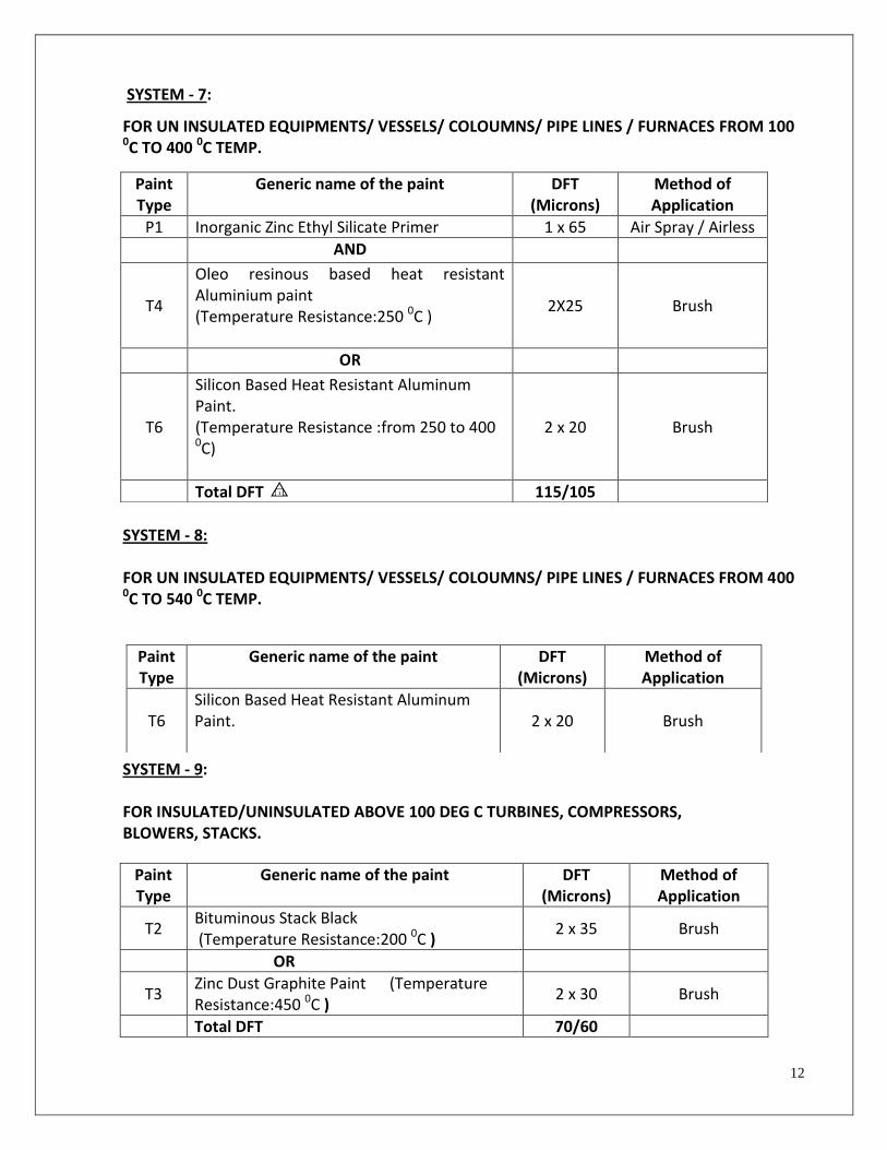
SYSTEM - 7:
FOR UN INSULATED EQUIPMENTS/ VESSELS/ COLOUMNS/ PIPE LINES / FURNACES FROM 100 0C TO 400 0C TEMP.
SYSTEM - 8: FOR UN INSULATED EQUIPMENTS/ VESSELS/ COLOUMNS/ PIPE LINES / FURNACES FROM 400 0C TO 540 0C TEMP. SYSTEM - 9: FOR INSULATED/UNINSULATED ABOVE 100 DEG C TURBINES, COMPRESSORS, BLOWERS, STACKS.
Paint Type
Generic name of the paint DFT (Microns)
Method of Application
P1 Inorganic Zinc Ethyl Silicate Primer 1 x 65 Air Spray / Airless
AND
T4
Oleo resinous based heat resistant Aluminium paint (Temperature Resistance:250 0C )
2X25 Brush
OR
T6
Silicon Based Heat Resistant Aluminum Paint. (Temperature Resistance :from 250 to 400 0C)
2 x 20 Brush
Total DFT 115/105
Paint Type
Generic name of the paint DFT (Microns)
Method of Application
T6 Silicon Based Heat Resistant Aluminum Paint.
2 x 20 Brush
Paint Type
Generic name of the paint DFT (Microns)
Method of Application
T2 Bituminous Stack Black (Temperature Resistance:200 0C )
2 x 35 Brush
OR
T3 Zinc Dust Graphite Paint (Temperature Resistance:450 0C )
2 x 30 Brush
Total DFT 70/60

13
SYSTEM- 10:
UNDERGROUND, UNDER SOIL (BURIED) PIPELINES UP TO 50 DEG C FOR OTHER THAN PLANT AREA i. e. EXCLUSIVELY FOR OFFSITE AREA
Notes:
1. Carry out shot blasting of the surface to Sa 2.5 finish. 2. Apply one coat of synthetic primer conforming to AWWA 203/2003 and IS 15337/2003
standards. The primer shall be compatible with the hot applied tape. 3. Use 2 layers of 2 mm thick each hot applied anti-corrosive tape conforming to AWWA
203/2003 and IS 15337/2003 standards. 4. Both the primer and tape shall be of one manufacturer for compatibility. 5. Ensure that the tape is tightly wound on the pipe. 6. Spirally wrap the self adhesive tape on the primed surface with 25 mm overlap. 7. The length of the tape shall be kept sufficiently extra to complete the length of the
pipeline. 8. The spiral joint if any shall have 25 mm overlap. 9. The tape coated pipes and the field joint coated area shall be holiday tested using
portable holiday tester using 12,000 volts. 10. Weld joints shall be coated only after hydro test.
SYSTEM - 11: UNDERGROUND, UNDER SOIL (BURIED) PIPELINES / STRUCTURES/VESSELS UP TO 100 DEG C
Generic name of the coating Thickness (mm)
Method of Application
Anti Corrosive Tape 2 x 2 mm Manual
Total DFT 4 mm
Paint Type
Generic name of the paint DFT (Microns)
Method of Application
P2 Epoxy red oxide zinc phosphate primer
1 x 60 Spray
F3 Epoxy Glass Flake (Amine Adduct) 2 x 200 Spray
Total DFT 460

14
SYSTEM - 12: UNDERGROUND, UNDER SOIL (BURIED) PIPELINES / VESSELS FROM 100 TO 480 DEG. C FOR CS AND 600 DEG. C FOR SS SURFACES.
B) PAINTING SYSTEMS USING MANUAL CLEANING TO St2 OR POWER TOOL CLEANING TO St3 AS SURFACE PREPARATION. SYSTEM – 13: FOR EXTERNAL SURFACE OF VESSEL, EQUIPMENT / COLOUMN / PIPING / ALL STRUCTURAL UP TO 100 0C TEMP.
(All areas in refinery including, Pipe Track No 14 , Pipe Track No. 9, SRU, ARU, CRU, FCCU (MEROX), CCU (Gas Treater), Pipe Track No. 7, CDU-VDU, HGU, Hydro Cracker, DHDS, New SRU, LOBS, DM Water Plant, Pipe Track No. 4 & 5 (Along Road No. 4 Up To Road No. 5 & Along Road No. 5 Up to Road No. 6), MINAS, SWPH, FLARE, JETTY, Jawahar Island & Acid/Caustic Tanks).
Paint Type
Generic name of the paint DFT (Microns)
Method of Application
T9 Heat resistant Engineered Polysiloxane
3x125 Spray
Total DFT 375
Paint Type
Generic name of the paint DFT (Microns)
Method of Application
P4 Self Priming surface tolerant Epoxy Mastic Paint
1 x 125 Brush
F1 High build two pack polyamide cured epoxy.
1 x 125 Brush
U1 Aliphatic acrylic modified high solids weather resistant recoatable two pack polyurethane (finish coat)
1 x 40 Roller/ Brush
Total DFT 290

15
SYSTEM - 14: OLD SEA WATER COOLING TOWER/RMP CT AROUND COOLING TOWER OF 100 M RADIUS (SALT WATER SPRAY AREA)
Note: Salt water spray areas will require fresh water blasting or fresh water (Max. Chloride content 50 ppm) mopping shall be carried out on Salt Water spray areas, before application of primer, to remove the salts deposited on metal surface. Mopping can be repeated before application of other coats to remove salts deposited on previous coats, if such deposits are suspected
SYSTEM-15: FOR ALL AREAS IN REFINERY EXCEPT ABOVE INCLUDING PUMPS / MOTORS / BLOWERS /ELECTRICAL PANELS
Paint Type
Generic name of the paint DFT (Microns)
Method of Application
P4 Self Priming Epoxy Mastic Paint 1 x 125 Brush
F2
Low VOC (Volatile Organic Compounds) two component internally flexibilised high build surface tolerant epoxy pigmented with Aluminium & or Lamellar Micaceous Iron oxide coating
1 x 125 Brush
U1 Aliphatic acrylic high solids weather resistant recoatable two pack polyurethane (finish coat)
1 x 40 Roller/ Brush
Total DFT 290
Paint Type
Generic name of the paint DFT (Microns)
Method of Application
P4 Self Priming Epoxy Mastic Paint 1 x 125 Brush
U1 Aliphatic acrylic modified high solids weather resistant recoatable two pack polyurethane (finish coat)
1X40 Brush
Total DFT 165
OR
P2 Epoxy Red Oxide Zinc Phosphate Primer 1 x 60 Brush
B1 Synthetic Enamel Paint 2 x 25 Brush
Total DFT 110

16
SYSTEM – 16:
FOR INSULATED EQUIPMENTS / VESSELS / COLUMNS / PIPELINES UPTO 200 0C TEMP. Note: SURFACE PREPARATION (Cu-SLAG BLASTING TO Sa 2.5 (Min. Profile 50 microns)
Paint Type
Generic name of the paint DFT (Microns)
Method of Application
T8
Two component high solid, High temperature(up to 200deg c dry heat) Phenolic CUI (corrosion under insulation) epoxy coating
2 x125
Spray /Brush
Total DFT 250
SYSTEM – 17:
FOR INSULATED EQUIPMENTS / VESSELS / COLUMNS / PIPELINES WITH OUT HEAT TRACER BELOW 100 0C. (For recoating of existing similar type of paint system)
SYSTEM – 18:
FOR INSULATED EQUIPMENTS / VESSELS / COLUMNS / PIPELINES WITH HEAT TRACER Above 100 0C. (For recoating of existing similar type of paint system).
OR
Paint Type
Generic name of the paint DFT (Microns)
Method of Application
F2
Low VOC (Volatile Organic Compounds) two component internally flexibilised high build surface tolerant epoxy pigmented with Aluminium & Lamellar Micaceous Iron oxide coating
2 x 100 Spray/Brush
Total DFT 200
Paint Type
Generic name of the paint DFT (Microns)
Method of Application
T3 Zinc Dust Graphite. (Temperature Resistance : up to 450 0C)
2 x 30 Brush
Total DFT 60
Paint Type
Generic name of the paint DFT (Microns)
Method of Application
T6 Silicon Based Heat Resistant Aluminum Paint. (Temperature Resistance :250 - 540 0C)
2 x 20 Brush
Total DFT 40
17
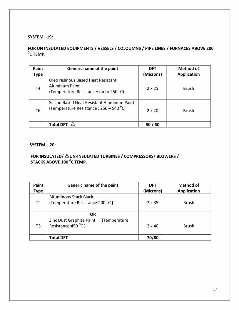
SYSTEM –19: FOR UN INSULATED EQUIPMENTS / VESSELS / COLOUMNS / PIPE LINES / FURNACES ABOVE 200 0C TEMP.
SYSTEM – 20: FOR INSULATED/ UN-INSULATED TURBINES / COMPRESSORS/ BLOWERS / STACKS ABOVE 100 0C TEMP.
Paint Type
Generic name of the paint DFT (Microns)
Method of Application
T2 Bituminous Stack Black (Temperature Resistance:200 0C )
2 x 35 Brush
OR
T3 Zinc Dust Graphite Paint (Temperature Resistance:450 0C )
2 x 40 Brush
Total DFT 70/80
Paint Type
Generic name of the paint DFT (Microns)
Method of Application
T4
Oleo resinous Based Heat Resistant Aluminum Paint (Temperature Resistance: up to 250 0C)
2 x 25 Brush
T6
Silicon Based Heat Resistant Aluminum Paint (Temperature Resistance : 250 – 540 0C) 2 x 20 Brush
Total DFT 50 / 50

18
C) INTERNAL PAINTING OF EQUIPMENT AND STOTRAGE TANKS – Cu-SLAG BLASTING TO Sa 2.5 (Min. Profile 50 microns) AS SURFACE PREPARATION
SYSTEM – 21: FOR EQUIPMENT – STEAM DRUM/STEAM CONDENSATE POT
Paint Type
Generic name of the paint DFT (Microns)
Method of Application
T1 Boiler composition interior paint(hot wet metal surface) 2 x 35 Brush
Total DFT 70
SYSTEM – 22:
FOR OVERHEAD PRODUCT ACCUMULATIONS EQUIPMENTS
SYSTEM – 23: FOR EQUIPMENTS-KOD/AIR VESSEL (NORMALLY BOTTOM SECTION), VESSELS CARRYING SALT WATER, EXCHANGER TUBE SHEETS, FLOAT HEAD, CHANNEL AND CHANNEL COVERS OF NON-FERROUS COOLERS & CONDENSERS.
Note : Surface preparation St2, St3 (manual/power tool cleaning shall be accepted as suit to site condition)
Paint Type
Generic name of the paint DFT (Microns)
Method of Application
P2 Epoxy red oxide zinc phosphate primer 1x60 Spray
F10 Epoxy Glass Flake (Amine Adduct) 1 x 200 Spray
Total DFT 260
Paint Type
Generic name of the paint DFT (Microns)
Method of Application
F7 Epoxy Coal Tar Paint 2 x 100 Brush
Total DFT 200

19
SYSTEM – 24: EXCHANGER TUBE SHEET, FLOAT HEAD, CHANNEL AND CHANNEL COVERS OTHER THAN NON-FERROUS COOLERS & CONDENSERS. Note: Surface preparation Sa 2.5
SYSTEM – 25: FOR LPG MOUNDED BULLETS (only from 4’O clock to 8’O clock position area) Note: Application of primer shall be as per Manufacturer’s Specifications.
In case the primer is not recommended by the paint manufacturer, then total DFT of the finished paint system shall be 660 microns
Paint Type
Generic name of the paint DFT (Microns)
Method of Application
P6 Two Component polyamide cured epoxy primer.
1 X60 Spray
F5 Two Component solvent free amine cured epoxy coating.
2 X 300 Air less spray
Total DFT 660
D) OTHER PAINTING SYSTEMS:
SYSTEM- 26:
FOR GI SURFACES (EXCLUDING GALVANISED THICKNESS)
Note: surface preparation is only cleaning of dust/oil contamination.
Paint Type
PAINT TYPE DFT (Microns)
Method of Application
P7 Epoxy red oxide zinc phosphate primer suitable for GI surfaces.
1X60 Brush/roller
U1 Aliphatic acrylic modified recoatable two pack polyurethane (finish coat)
1X40 Brush/roller
Total DFT 100
Paint Type
Generic name of the paint DFT (Microns)
Method of Application
F9 Solvent free amine cured epoxy reinforced with glass flakes.
2 x 500 Spray
Total DFT 1000

20
E) SPECIAL PAINTING / COATING SYSTEM
SYSTEM-27: EXTERNAL THERMAL INDICATIVE PAINT FOR COLD COLLECTOR VESSELS OF REFORMER FURNACES (HGU & NHGU, FCCU REGENERATOR ): ABRASIVE CU SLAG SHOT BLASTING TO SA 2.5.
SYSTEM-28 : SEA COOLING WATER SERVICE INTERNAL LINING OG 30”NB DIA AND ABOVE IN RMP UNITS: SURFACE PREPARATION: ABRASIVE CU SLAG SHOT BLASTING TO SA 2.5
Note: Application of primer shall be as per Manufacturer’s Specifications. In case the primer is not recommended by the paint manufacturer, then total DFT of the finished paint system shall be 1065 microns
Detail procedure shall get approved from BPCL inspection in line with indicative system.
Paint Type
Generic name of the paint DFT (Microns)
Method of Application
P1 Inorganic Zinc Ethyl Silicate Primer 1x65 Air Spray / Airless
T10 A single pack, temperature indicating paint based upon a modified silicone (Intertherm 715 of AKZONBEL equivalent). (The colour to change from green to blue at temperatures between 180-220°C (356-428°F), and from blue to white at temperatures between 310-350°C (590-662°F).
2X25 Air spray
Total DFT 115
Paint Type
Generic name of the paint DFT (Microns)
Method of Application
P1 Inorganic Zinc Ethyl Silicate Primer 1 x 65 Spray
F9
Solvent free, epoxy cured with polyamine/modified polyamine/polyamine adduct coating reinforced with glass fibre/flakes. SIGMAA SHIELD 905 of Sigma coatings, INTERLINE 925 GF of Akzo Nobel, or equivalent as approved.
2X500
Spray
Total DFT 1065

21
8.0 DETAILED PAINT SPECIFICATIONS 8.1 LIST OF PRIMERS & FINISH PAINTS Note: For all internal lining / internal painting works, manufacturer’s laboratory test statement /
Laboratory Paint performance certificates to be submitted by paint manufacturers & checked
apart from material test certificates for specified services at operating temperature and
condition. Material shall be procured from only those approved manufacturers who will meet the
above stated criteria.
SR. NO.
PRIMER PAINT TYPE
SPECIFIED VOL. SOLIDS
1 Inorganic Zinc ethyl silicate primer (Minimum 85% Zinc dust by weight in the dried film)
P1 60 2 %
2 Epoxy red oxide zinc phosphate primer P2 50 2 %
3 Self priming surface tolerant epoxy mastic paint P4 80 ±2 %
4 Amine Adduct Cured Epoxy Holding Primer P5 60 3 %
5 Two Component Polyamide cured Epoxy Primer P6 57%±2 %
6 Epoxy red oxide zinc phosphate PRIMER SUITABLE FOR GI SURFACE
P7 50 3 %
FINISH PAINTS
7 High build two pack ployamide cured epoxy F1 60 2%
8 Low VOC High build Surface tolerant Epoxy pigmented with Al, Micaceous iron oxide
F2 80%
9 Epoxy glass flake paint (amine adduct -Buried Pipelines) F3 87 3%
10 Two pack Epoxy based tank liner (Amine cured) F4 60 2 %
11 Two Component solvent free amine cured epoxy (Immersion services)
F5 100%
12 Solvent Free Epoxy amine cured (Potable Water ) F6 100%
13 Epoxy coal tar paint (Immersion Grade) F7 64 2%
14 Solvent free amine cured epoxy reinforced with glass flakes. (Sea Water Pipeline internal)
F9 100
15 Epoxy glass flake paint (amine adduct)(IMMERSION SERVICES)
F10 90 ± 3%
HIGH TEMPERATURE PAINTS
16 Boiler composition T1 40 ± 2 %
17 Bituminous stack black T2 40 ± 2 %
18 Zinc dust graphite paint T3 40 ± 2 %
19 Oleoresinous based heat resistant Aluminium paint (up to 250 deg. C)
T4 30 ± 2 %

22
SR. NO.
PRIMER PAINT TYPE
SPECIFIED VOL. SOLIDS
20 Silicone Heat resistant Aluminum paint (400 - 600 deg. C)
T6 28 ± 2 %
21 Two component high solid, high temperature phenolic CUI (corrosion under insulation Epoxy coating (UP TO 200 DEG. C)
T8 67 2%
22 Heat resistant Engineered Polysiloxane T9 75 ± 2%
23 Temperature indicating paint based upon modified silicone
T10 42 ± 2%
24 Two component high solid High temperature (suitable up to minimum 120 deg C. immersed heat) phenolic / phenolic novalac epoxy coating.
T11 67 2%
POLYURETHANE PAINTS
25 Acrylic Aliphatic weather resistant recoatable polyurethane paint
U1 2%
ALKYD BASED PAINT
26 Synthetic enamel paint B1 40 ± 2 %
27 Oil based Aluminium paint B2 40 ± 2 %
For Brand Names Refer Annexure - I 8.2 PAINT SPECIFICATIONS PDS: Product Data Sheets. PRIMER 1) Inorganic Zinc Ethyl Silicate Primer (P1):
Colour : Grey
Finish : Matt
Type : 2 pack inorganic ethyl silicate
Application : By brush or Airless spray
Dry film thickness/coat : 60 – 70 µm
Pigment (main) : Minimum 85% Zinc dust by weight in the dried film
Volume solids : 60 2%
Area coverage (theoretical) : 6 to 7 sq.m/litre
Surface dry : 2 hrs.
Hard dry : 24 hrs.
Over coating : As per Manufacturer’s PDS
Recoatability : As per Manufacturer’s PDS
Full cure : As per Manufacturer’s PDS

23
Shelf life : As per Manufacturer’s PDS
Temperature Resistance : 400 0C
2) Epoxy Red Oxide Zinc Phosphate Primer (P2):
Colour : Red
Finish : Semi gloss
Application : Airless/Airspray/Brush
Pigment (main) : Zinc phosphate content minimum 5 – 10 % by weight of the total pigments
Type of epoxy
: Condensation product of bisphenol – A and epichlorohydrin with terminal Epoxide groups.
Curing agent : Polyamide (amine value 210-230)
Volume solids : 50 2 %
DFT : 60 - 70 microns
Area Coverage (Theoretical) : 8 - 10 sq.m / litre
Surface dry : 8 hrs.
Hard dry : 24 hrs.
Recoatability : As per Manufacturer’s PDS
Full cure : As per Manufacturer’s PDS
Shelf life : As per Manufacturer’s PDS
3) Self Priming Surface Tolerant Epoxy Mastic Paint (P4):
Colour : As desired
Finish : Semi-Glossy
Type : Two pack
Application : By brush or Airless spray
Dry film thickness/coat : 100 – 125 µm
Volume solids : 80 ±2 %
Area coverage (theoretical) : 6.5 to 8 sq.m/litre
Surface dry : 6 hrs.
Hard dry : 16 hrs.
Recoatability : As per Manufacturer’s PDS
Full cure : As per Manufacturer’s PDS
Shelf life : As per Manufacturer’s PDS
4) Amine /Amine Adduct Cured Epoxy Holding Primer (P5):
Colour : Red brown / greenish grey /self standard
Finish : Low Metallic Sheen
Type : Two pack
Application : By brush or Airless spray

24
Dry film thickness/coat : 60 µm
Volume solids : 60 ±3 %
Area coverage (theoretical) : 12 sq.m/litre
Surface dry : 2 hrs.
Hard dry : 16 hrs.
Recoatability : As per Manufacturer’s PDS
Full cure : As per Manufacturer’s PDS
Shelf life : As per Manufacturer’s PDS
5) Two Component Polyamide Cured Epoxy Holding Primer : (P6):
Colour : Yellow / Green /self standard
Finish : Egg shell
Type : Two Packs
Application : Airless Spray, Air Spray, Brush, Roller
DFT per coat : 60 microns
Volume Solids : 57 3 %
Theoretical Coverage : 11.4M² / Lt. @ 50 µ DFT
Surface Dry (25 Deg C) : 1.5 hrs.
Hard Dry (25 Deg C) : 16 hrs.
Minimum Over coating Time : As per Manufacturer’s PDS
Maximum Over coating Time : As per Manufacturer’s PDS
Shelf Life : As per Manufacturer’s PDS
6) Epoxy Red Oxide Zn Phosphate Primer Suitable For GI Surfaces: (P7):
Colour : Red
Finish : Semi gloss
Application : Airless/Airspray/Brush
Pigment (main) : Zinc phosphate content minimum 5 – 10 % by weight of the total pigments
Type of epoxy : Condensation product of bisphenol – A and epichlorohydrin with terminal Epoxide
Curing agent : Polyamide (amine value 210-230)
Volume solids : 50 3 %
DFT : 60 - 70 microns
Area Coverage (Theoretical) : 8 - 10 sq.m / litre
Surface dry : 8 hrs.
Hard dry : 24 hrs.
Recoatability : As per Manufacturer’s PDS
Full cure : As per Manufacturer’s PDS
Shelf life : As per Manufacturer’s PDS

25
FINISHED PAINTS
7) High Build Two Pack Polyamide Cured Epoxy (F1):
Colour : White /Grey
Finish : Semi Gloss / Matt
Type : Two Packs
Application : By brush or Air/Airless spray
Dry film thickness/coat : 100-150 m
Volume solids : 60 2%
Area coverage (theoretical) : 8 to 10 sq. m/ litre
Surface dry : 4 hrs.
Hard dry : 24 hrs.
Over coating : As per Manufacturer’s PDS
Recoatability : As per Manufacturer’s PDS
Full cure : As per Manufacturer’s PDS
Shelf life : As per Manufacturer’s PDS
8) Low VOC High Build Surface Tolerant Epoxy Pigmented with Al & Micaceous Iron Oxide
(F2):
Colour : Aluminum / Grey / Red
Finish : Egg Shell
Type : Two Packs
Application : Airless Spray, Air Spray, Brush, Roller
DFT per coat : 125 ±25 microns
Volume Solids : 80
Theoretical Coverage : 5.30 square meters per liter at 150 microns DFT
Surface Dry (25 Deg C) : 6 hrs
Hard Dry (25 Deg C) : 16 hrs
Minimum Over coating Time : As per Manufacturer’s PDS
Maximum Over coating Time : As per Manufacturer’s PDS
Shelf Life : As per Manufacturer’s PDS
9) Epoxy Glass Flake Paint (Amine Adduct) for Buried pipelines) (F3):
Colour : As desired
Finish : Semi-Glossy
Type : Two packs
Application : By brush or Airless spray
Dry film thickness/coat : 200– 210 µm
Volume solids : 87 3%
Area coverage (theoretical) : 4 to 4. 5 sq.m/litre

26
Surface dry : 8 hrs.
Hard dry : 24 hrs.
Recoatability : As per Manufacturer’s PDS
Over coating : As per Manufacturer’s PDS
Full cure : As per Manufacturer’s PDS
Shelf life : As per Manufacturer’s PDS
10) Two Pack Epoxy Based Tank Liner (Amine Cured) (F4):
Colour : White/Grey
Finish : matt
Type : Two pack
Application : By brush or Airless spray
Volume solids : 60 2%
Type of epoxy : Condensation product of bisphenol-A and epichlorohydrin with terminal epoxide groups.
Dry film thickness /coat : 75 - 125 microns
Spreading rate : 4 – 5 sq.m / litre
Surface dry : 2-3 hrs.
Hard dry : 16-24 hrs.
Recoatability : As per Manufacturer’s PDS
Full cure : As per Manufacturer’s PDS
Shelf life : As per Manufacturer’s PDS
11) Two Component Solvent Free Amine Cured Epoxy Immersed Services (F5):
Colour : Green / Off white
Finish : Glossy
Type : Two Packs
Application : Airless Spray, Air Spray
DFT per coat : 300 µ
Volume Solids : 100 %
Theoretical Coverage : 3.3 M² / Lt. @ 300 µ DFT
Surface Dry (25 Deg C) : 8 hrs.
Hard Dry (25 Deg C) : 24 hrs
Minimum Over coating Time : As per Manufacturer’s PDS
Maximum Over coating Time : As per Manufacturer’s PDS
Shelf Life : As per Manufacturer’s PDS

27
12) Solvent Free Epoxy Amine Cured (Potable Water Certificate) (F6):
Colour : green / white
Finish : Glossy / semi gloss
Type : Two pack
Application : By brush or Airless spray
Dry film thickness/coat : 300 µm
Volume solids : 100 %
Area coverage (theoretical) : 3.3 sq.m/litre
Surface dry : 8 hrs.
Hard dry : 16 hrs.
Recoatability : As per Manufacturer’s PDS
Full cure : As per Manufacturer’s PDS
Shelf life : As per Manufacturer’s PDS
13) Epoxy Coal Tar Paint Immersion Grade (F7):
Colour : Brown/Black
Finish : Egg shell
Application : Airless / Airspray / Brush
Volume solids : 64 2%
Coaltar content : 35 - 40% by volume
DFT : 90-120 microns
Area Coverage (Theoretical) : 5-7 sq.m / litre
Surface dry : 8 hrs.
Hard dry : 24 hrs.
Recoatability : As per Manufacturer’s PDS
Full cure : As per Manufacturer’s PDS
Shelf life : As per Manufacturer’s PDS
14) Solvent Free Amine Cured Epoxy Reinforced With Glass Flakes: (F9):
Colour : Green - gloss
Type : Single pack
Application : Airless spray
Dry film thickness/coat : 100 %
Volume solids : 400-500 µm
Area coverage (theoretical) : 2.5 sq.m/litre for 400 µm
Touch dry : 8 hrs.
Recoatability : As per Manufacturer’s PDS
Full cure : As per Manufacturer’s PDS
Shelf life : As per Manufacturer’s PDS

28
15) Epoxy Glass Flake Paint (Amine Adduct)(Immersion services) (F10):
Colour : As desired
Finish : Semi-Glossy
Type : Two packs
Application : By brush or Airless spray
Dry film thickness/coat : 200– 210 µm
Volume solids : 90 3%
Area coverage (theoretical) : 4 to 4. 5 sq.m/litre
Surface dry : 8 hrs.
Hard dry : 24 hrs.
Recoatability : As per Manufacturer’s PDS
Over coating : As per Manufacturer’s PDS
Full cure : As per Manufacturer’s PDS
Shelf life : As per Manufacturer’s PDS
HIGH TEMPERATURE PAINTS 16) Boiler Composition (T1):
Colour : Black
Finish Matt
Type Single pack
Application Brush
Volume solids 40 ± 2 %
Pigment content 34% +/- 2%
Binder content 26% +/- 2%
Temperature resistance (WET) 5400 C.
DFT 35-40 microns
Area Coverage (Theoretical) 11-14 sq.m / litre
Surface dry 4-6 hrs.
Hard dry 24 hrs.
Recoatability As per Manufacturer’s PDS
Full cure As per Manufacturer’s PDS
Shelf life As per Manufacturer’s PDS
(The tests shall conform to IS 101 - 1964.)
Note: After hard dry time filled the equipment with water and raised the temp up to 100 deg. C and hold it for 8 hrs for complete curing of product.
29
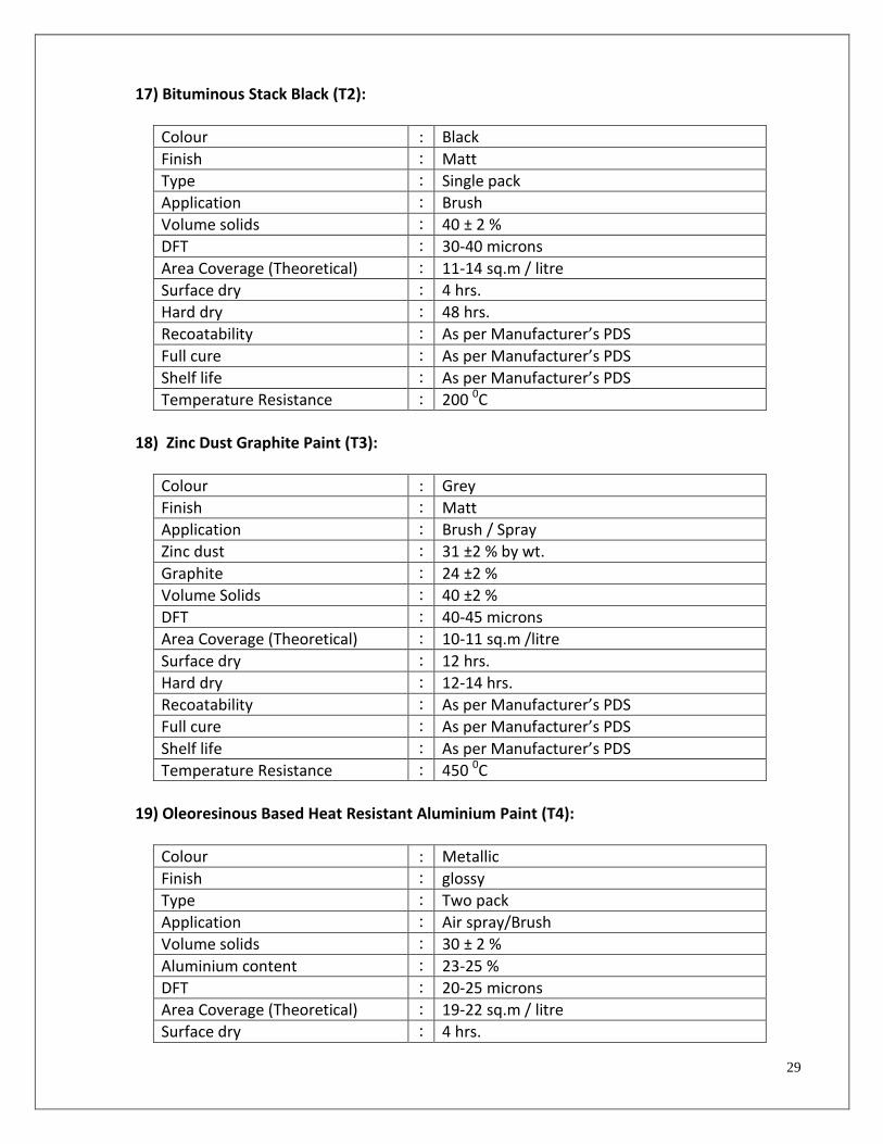
17) Bituminous Stack Black (T2):
Colour : Black
Finish : Matt
Type : Single pack
Application : Brush
Volume solids : 40 ± 2 %
DFT : 30-40 microns
Area Coverage (Theoretical) : 11-14 sq.m / litre
Surface dry : 4 hrs.
Hard dry : 48 hrs.
Recoatability : As per Manufacturer’s PDS
Full cure : As per Manufacturer’s PDS
Shelf life : As per Manufacturer’s PDS
Temperature Resistance : 200 0C
18) Zinc Dust Graphite Paint (T3):
Colour : Grey
Finish : Matt
Application : Brush / Spray
Zinc dust : 31 ±2 % by wt.
Graphite : 24 ±2 %
Volume Solids : 40 ±2 %
DFT : 40-45 microns
Area Coverage (Theoretical) : 10-11 sq.m /litre
Surface dry : 12 hrs.
Hard dry : 12-14 hrs.
Recoatability : As per Manufacturer’s PDS
Full cure : As per Manufacturer’s PDS
Shelf life : As per Manufacturer’s PDS
Temperature Resistance : 450 0C
19) Oleoresinous Based Heat Resistant Aluminium Paint (T4):
Colour : Metallic
Finish : glossy
Type : Two pack
Application : Air spray/Brush
Volume solids : 30 ± 2 %
Aluminium content : 23-25 %
DFT : 20-25 microns
Area Coverage (Theoretical) : 19-22 sq.m / litre
Surface dry : 4 hrs.

30
Hard dry : 16 hrs.
Recoatability : As per Manufacturer’s PDS
Full cure : As per Manufacturer’s PDS
Shelf life : As per Manufacturer’s PDS
Temperature Resistance : 250 0C
20) Silicone Heat Resistant Aluminum Paint (T6):
Colour : Grey
Finish : Semi gloss
Application : Airless/Airspray/Brush
Volume solids : 28 ± 2 %
DFT : 20-25 microns
Area Coverage (Theoretical) : 11-14 sq.m / litre
Surface dry : 2 hr.
Hard dry : 16 hrs.
Recoatability : As per Manufacturer’s PDS
Full cure : As per Manufacturer’s PDS
Shelf life : As per Manufacturer’s PDS
Temperature Resistance : 400 – 600 0C
21) Two Component High Solid, High Temperature Phenolic CUI (Corrosion Under
Insulation) Epoxy Coating (T8):
Colour : Buff, light grey
Finish : Matt
Type : Two pack
Application : By brush or Airless spray
Dry film thickness/coat : 80-125µm
Volume solids : 67± 2 %
Area coverage (theoretical) : 5-8 sq.m/litre
Surface dry : 6 hrs.
Hard dry : 16 hrs.
Recoatability : As per Manufacturer’s PDS
Full cure : As per Manufacturer’s PDS
Shelf life : As per Manufacturer’s PDS
Dry heat : up to 200deg c
22) Heat Resistant Engineered Polysiloxane – (T9):
Colour : Grey
Finish : Glossy
Type : Two pack

31
Application : By brush or Airless spray
Dry film thickness/coat : 125-200 µm
Volume solids : 75± 2 %
Area coverage (theoretical) : 6 sq.m/litre for 125 µm
Surface dry : 4 hrs.
Hard dry : 5 hrs.
Recoatability : As per Manufacturer’s PDS
Full cure : As per Manufacturer’s PDS
Shelf life : As per Manufacturer’s PDS
Dry heat : up to 600 deg c
Note: (Holiday testing is not reliable due to presence of metallic pigments)
23) Temperature Indicating Paint Based Upon Modified Silicone (T10):
Colour : Green (at ambient temperature)
Finish : Eggshell
Application : Airless/Airspray/Brush
Volume solids : 42 ± 2 %
DFT : 20-25 microns
Area Coverage (Theoretical) : 16 sq.m / litre
Surface dry : 1 hr.
Hard dry : 3 hrs.
Recoatability : As per Manufacturer’s PDS
Full cure : As per Manufacturer’s PDS
Shelf life : As per Manufacturer’s PDS
24) Two Component High Solid, High Temperature Phenolic / phenolic novalac Epoxy
Coating Suitable up to Minimum 120 Deg. C Immersion Services (T11):
Colour : Buff, light grey
Finish : Matt
Type : Two pack
Application : By brush or Airless spray
Dry film thickness/coat : 80-125µm
Volume solids : 67± 2 %
Area coverage (theoretical) : 5-8 sq.m/litre
Surface dry : 6 hrs.
Hard dry : 16 hrs.
Recoatability : As per Manufacturer’s PDS
Full cure : As per Manufacturer’s PDS
Shelf life : As per Manufacturer’s PDS
Immersed heat : up to 120 deg c
32
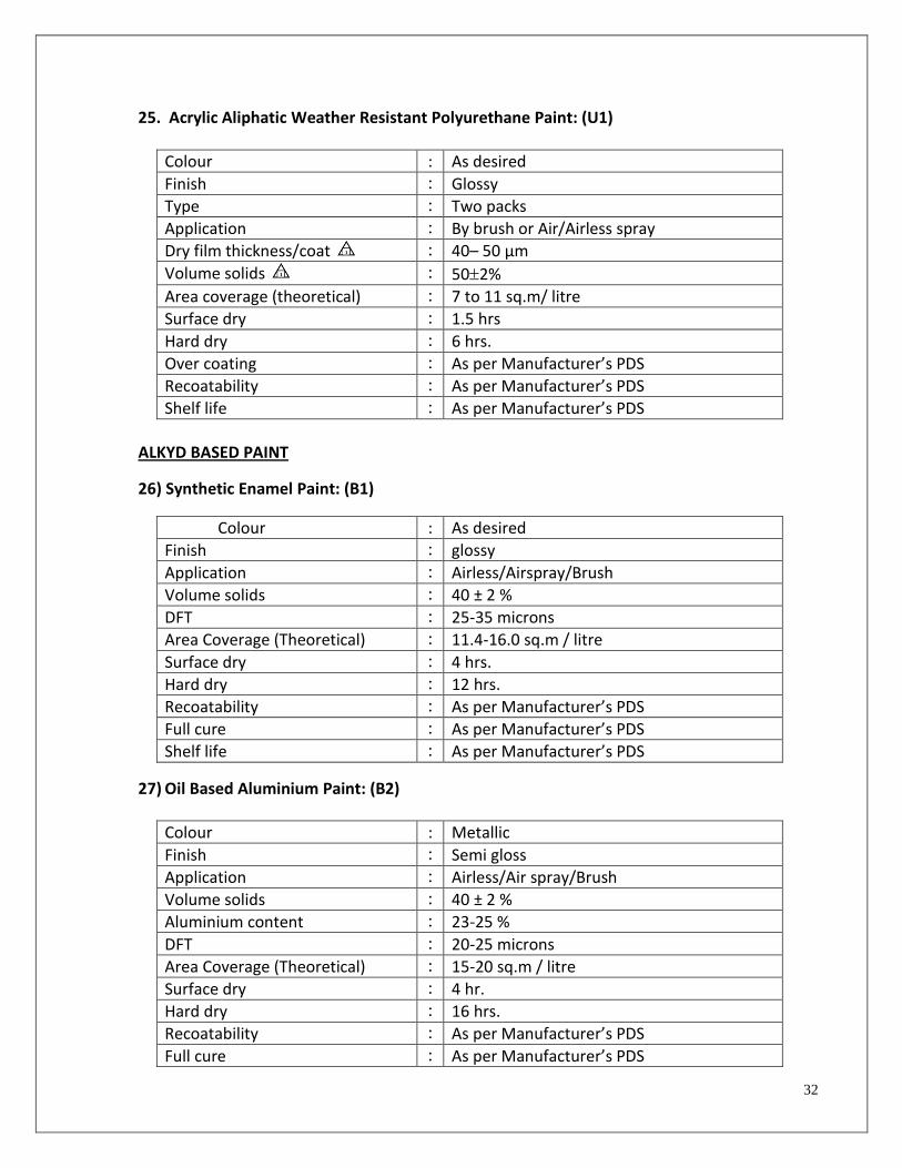
25. Acrylic Aliphatic Weather Resistant Polyurethane Paint: (U1)
Colour : As desired
Finish : Glossy
Type : Two packs
Application : By brush or Air/Airless spray
Dry film thickness/coat : 40– 50 µm
Volume solids : 502%
Area coverage (theoretical) : 7 to 11 sq.m/ litre
Surface dry : 1.5 hrs
Hard dry : 6 hrs.
Over coating : As per Manufacturer’s PDS
Recoatability : As per Manufacturer’s PDS
Shelf life : As per Manufacturer’s PDS
ALKYD BASED PAINT
26) Synthetic Enamel Paint: (B1)
Colour : As desired
Finish : glossy
Application : Airless/Airspray/Brush
Volume solids : 40 ± 2 %
DFT : 25-35 microns
Area Coverage (Theoretical) : 11.4-16.0 sq.m / litre
Surface dry : 4 hrs.
Hard dry : 12 hrs.
Recoatability : As per Manufacturer’s PDS
Full cure : As per Manufacturer’s PDS
Shelf life : As per Manufacturer’s PDS
27) Oil Based Aluminium Paint: (B2)
Colour : Metallic
Finish : Semi gloss
Application : Airless/Air spray/Brush
Volume solids : 40 ± 2 %
Aluminium content : 23-25 %
DFT : 20-25 microns
Area Coverage (Theoretical) : 15-20 sq.m / litre
Surface dry : 4 hr.
Hard dry : 16 hrs.
Recoatability : As per Manufacturer’s PDS
Full cure : As per Manufacturer’s PDS

33
9.0 BUILDING PAINTS
This section covers various building paints and also concrete and rebar coating
UNDERGROUND SURFACE All under-ground surfaces shall be coated with 2 coats of coal tar epoxy PLANT CONCRETE SURFACE: Premium acrylic Anti carbonate painting (Sunext-8 of M/s Sunanda chemicals or equivalent) of four coats on fresh surface; 2 coats on old surface.( note: after scrap cleaning fill the cracks cavities with suitable polymer mortar like Poly fill AR/Polyalk EP.
BUILDINGS & SHEDS TABLE – 3:
TYPE
Sheds
Other buildings
Important Buildings such as admin. bldg., control rooms, main gate house etc.
Building external
Cement based paint- 2 coats over a coat of primer.
Cement based sandtex mat- 2 coats over a coat of primer.
Antifungal, anti-algae acrylic copolymer paint
Building internal
Flat oil paint – 2 coats over a coat of primer.
Acrylic distemper – 2 coats over 2 coats of solvent thinnable primer.
Acrylic emulsion/ plastic emulsion – 3 coats over 2 coats of solvent thinnable primer.
Building ceiling Flat oil paint – 2 coats over a coat of primer.
Acrylic distemper – 2 coats over 2 coats of solvent thinnable primer
Acrylic distemper – 2 coats over 2 coats of solvent thinnable primer
Metal surface
Synthetic enamel – 2 coats over a coat of primer.
Anodizing / powder coating
Anodizing / powder coating
Wooden surface
Synthetic enamel – 2 coats over a coat of wooden primer.
French polish –min.2 coats or Synthetic enamel – 2 coats over a coat of wood primer.
French polish –min. 2 coats or Synthetic enamel – 2 coats over a coat of wood primer.
AC sheets (Ver- tical Cladding)
Antifungal, anti-algae acrylic copolymer paint
Cooilng water sump/basin
Coal tar epoxy-2 coats

34
10.0 STANDARD FOR COLOUR CODING OF PIPELINES/EQUIPMENTS Non-uniformity of colour coding of pipelines in industrial installations causes faulty
manipulation of valves, cutting of lines, welding on line carrying hazardous or inflammable material etc. resulting in to the destruction of property and injury to personnel. Uniformity of colour promotes greater safety, lessens the chances of error and warns against the hazards involved in the handling of material inside the pipelines.
Identification of the particular contents of the pipelines is achieved by imposing suitable colour bands on the ground colour. Letter writing as a mode of identification, is also recommended for chemical industry, as this will reduce the possibility of mistakes in identification. Lettering may include the contents by name, chemical formula, or unmistakable and standard abbreviations.
10.1 This standard prescribes the colour scheme for the identification of the contents of pipelines
carrying fluids in the BPCL refinery.
This standard is not applicable to pipelines buried underground or used for electrical services.
PAINTS
Appropriate quality of paints conforming to relevant BPCL standards, wherever they exist, shall be used for colour marking.
It is recommended that the paints used should produce a glossy finish.
COLOURS
In order to identify the contents of the pipelines, a large number of colour shades are required. Recommendations regarding shades of colour that may be used are given in Table 4. Colours used should be near to the specified colour shade as possible.
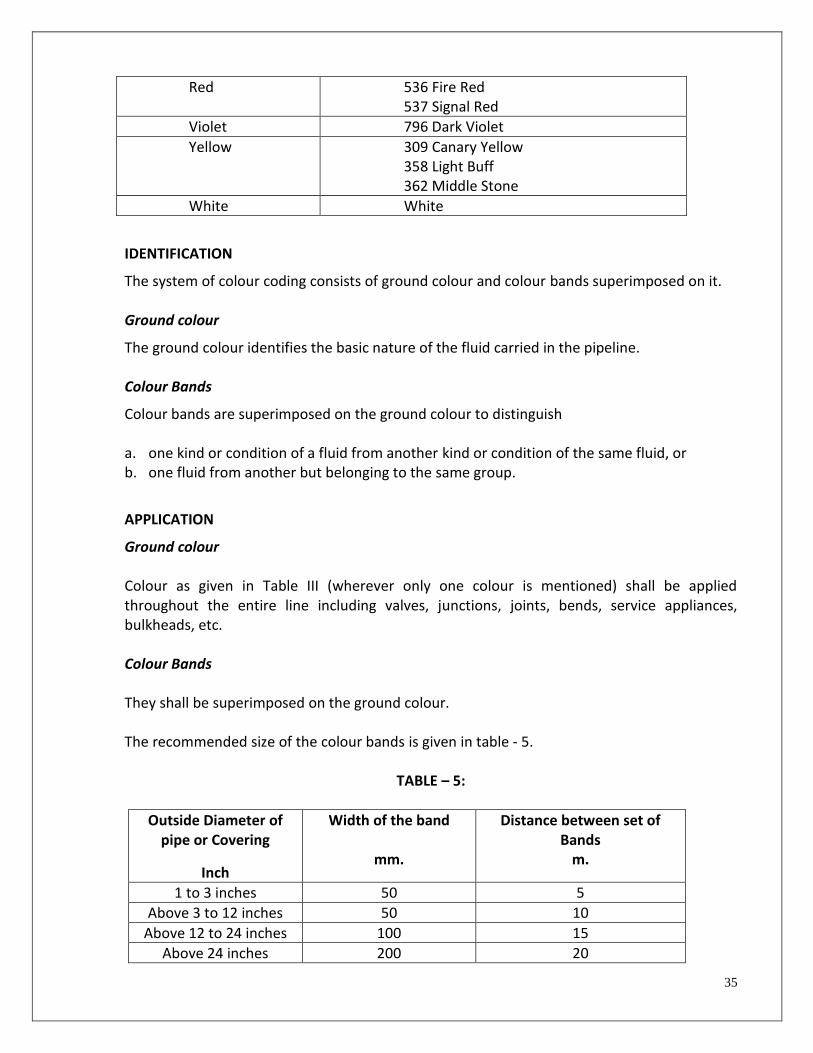
TABLE – 4: DISTINCT SHADES OF COLOURS TO BE USED FOR CODING
SHADE NO. AND ITS DESCRIPTION ACCORDING TO IS 5 – 2007.
COLOUR SHADE NO.
Black Black
Blue 108 Aircraft Blue 174 Orient Blue
Brown 412 Dark Brown 413 Salmon Pink 414 Golden Brown
Grey 692 Smoke Grey
Orange 592 international orange
35
Red 536 Fire Red 537 Signal Red
Violet 796 Dark Violet
Yellow 309 Canary Yellow 358 Light Buff 362 Middle Stone
White White
IDENTIFICATION
The system of colour coding consists of ground colour and colour bands superimposed on it.
Ground colour
The ground colour identifies the basic nature of the fluid carried in the pipeline.
Colour Bands
Colour bands are superimposed on the ground colour to distinguish
a. one kind or condition of a fluid from another kind or condition of the same fluid, or b. one fluid from another but belonging to the same group.
APPLICATION
Ground colour Colour as given in Table III (wherever only one colour is mentioned) shall be applied throughout the entire line including valves, junctions, joints, bends, service appliances, bulkheads, etc. Colour Bands They shall be superimposed on the ground colour.
The recommended size of the colour bands is given in table - 5.
TABLE – 5:
Outside Diameter of pipe or Covering
Inch
Width of the band
mm.
Distance between set of Bands
m.
1 to 3 inches 50 5
Above 3 to 12 inches 50 10
Above 12 to 24 inches 100 15
Above 24 inches 200 20

36
The minimum gap shall be of 50mm between adjacent band.
For hot lines, which are insulated, painting of bands should be done in plain Aluminium sheet, which can be easily screwed to the pipeline.
Valves shall be painted with the same colour as the main pipelines except the valves shall be painted red for firefighting; yellow with black diagonal strips for warning of danger and Brilliant green colour, to denote pipes carrying fresh water, either potable or non-potable. The colour coding as prescribed in this standard for pipelines in BPCL refinery for general services, process pipelines and pipelines conveying industrial gases (except pipelines conveying medical gases) are given in Table – III.
ADDITIONAL IDENTIFICATION
When further identification is required, this may be done as per the requirement of Operation Department.
10.2 Lettering
The recommended size of lettering for pipes of different diameters is given in table – 6.
TABLE - 6
Outside Diameter of pipe or Covering mm.
Size of legend mm.
20 to 30 10
Above 30 to 50 20
Above 50 to 80 30
Above 80 to 150 40
Above 150 to 250 63
Over 250 90
Direction of Flow
Where it is required to indicate the direction of flow, arrows or letters may be painted near valves, junctions, walls etc. and at suitable intervals along the pipe. These shall be black or white in colour and in contrast to the colour on which they are superimposed. If a label or badge with codified indication is attached to the pipe, the direction of flow may be indicated by the pointed end of the label or badge. VISIBILITY MARKINGS
Attention would be given to the visibility of colour markings and the letters. Where the pipelines are located above the normal line of vision of the operator, the lettering should be placed below the horizontal line of the pipe.

37
10.3 TABLE – 7: COLOUR CODE FOR PIPE LINES/EQUIPMENT IN BPCL REFINERY ( All colour code
bands /sign writing shall be with synthetic enamel paint)
A. UTILITES:
Sr. No.
DESCRIPTION OF THE PRODUCT
GROUND COLOUR COLOUR BANDS
1. FIRE WATER FIRE RED (No.536) NIL
2. COOLING WATER SEA GREEN (No.217) NIL
3. RAW/DOMESTIC WATER BRILLIANT GREEN (No.221) NIL
4. DM WATER ALUMINIUM 1 BRILLIANT GREEN (No.221)
5. BFW/CONDENSATE ALUMINIUM 2 BRILLIANT GREEN (No.221)
6. DRINKING WATER ALUMINIUM 3 BRILLIANT GREEN (No.221)
7. INSTRUMENT AIR AIR CARFT BLUE (No.108) NIL
8. PLANT AIR ORIENT BLUE (No.174) NIL
9. NITROGEN CANARY YELLOW (No.309) 1 BLACK BAND
10 15 KG STEAM ALUMINIUM 2 SIGNAL RED (No.537)
11. 3.5 KG STEAM ALUMINIUM 4 SIGNAL RED (No.537)
12. 1.0 KG STEAM ALUMINIUM 5 SIGNAL RED (No.537)
13. FLARE ALUMINIUM CANARY YELLOW (No.309)
B. PRODUCT RUNDOWN:
Sr. No.
DESCRIPTION OF THE PRODUCT
GROUND COLOUR COLOUR BANDS
1. FUEL GAS CANARY YELLOW (No.309) NIL
2. LPG ALUMINIUM 2 CANARY YELLOW (No. 309)
3. C3 STREAM ALUMINIUM 1 CANARY YELLOW (No. 309)
4. C4 STREAM ALUMINIUM 3 CANARY YELLOW (No. 309)
5. GASOLINE SALMON PINK (No.443) NIL
6. KEROSENE SMOKE GREY (No.692) NIL
7. ATF ALUMINIUM 4 ORIENT BLUE (No.174)
8. MT ALUMINIUM 4 SMOKE GREY (No.692)
9. HSD LIGHT BUFF (No.358) NIL
10 SBP 55/115 MIDDLE STONE (No.362) NIL
11 SBP 64/69 ALUMINIUM 1 MIDDLE STONE (No.362)
12 BENZENE WHITE NIL
13 TOULENE WHITE 4 MIDDLE STONE (No.362)
14 SLOPS SMOKE GREY (No.692) 1 BLACK
15 LSHS/FO/CLO ALUMINIUM 3 BLACK
16 NAPHTHA ALUMINIUM 1 SALMON PINK (No.443)
38
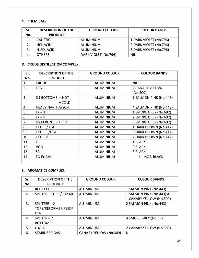
C. CHEMICALS:
Sr. No.
DESCRIPTION OF THE PRODUCT
GROUND COLOUR COLOUR BANDS
1. CAUSTIC ALUMINIUM 1 DARK VIOLET (No.796)
2. HCL ACID ALUMINIUM 2 DARK VIOLET (No.796)
3. H2SO4 ACID ALUMINIUM 3 DARK VIOLET (No.796)
4. OTHERS DARK VIOLET (No.796) NIL
D. CRUDE DISTILLATION COMPLEX:
Sr. No.
DESCRIPTION OF THE PRODUCT
GROUND COLOUR COLOUR BANDS
1. CRUDE ALUMINIUM NIL
2. LPG ALUMINIUM 2 CANARY YELLOW (No.309)
3. D4 BOTTOMS – HOT – COLD
ALUMINIUM 1 SALMON PINK (No.443)
4. HEAVY NAPTHA/SCN ALUMINIUM 4 SALMON PINK (No.443)
5. LK – 1 ALUMINIUM 1 SMOKE GREY (No.692)
6. LK – II ALUMINIUM 2 SMOKE GREY (No.692)
7. Hy KERO/HCP KERO ALUMINIUM 3 SMOKE GREY (No.692)
8. GO – I / LGO ALUMINIUM 1 DARK BROWN (No.412)
9. GO – III /HGO ALUMINIUM 3 DARK BROWN (No.412)
10. GO – IV ALUMINIUM 4 DARK BROWN (No.412)
11. LR ALUMINIUM 1 BLACK
12. VGO ALUMINIUM 2 BLACK
13. SR ALUMINIUM 3 BLACK
14. FO Ex B/H ALUMINIUM 4 NOS. BLACK
E. AROMATICS COMPLEX:
Sr. No.
DESCRIPTION OF THE PRODUCT
GROUND COLOUR COLOUR BANDS
1. RFU FEED ALUMINIUM 1 SALMON PINK (No.443)
2. SPLITER – TOPS / IBP-60 ALUMINIUM 1 SALMON PINK (No.443) & 1 CANARY YELLOW (No.309)
3. SPLITTER – 2 TOPS/REFORMER FEED/ DSN
ALUMINIUM 2 SALMON PINK (No.443)
4. SPLITER – 2 BOTTOMS
ALUMINIUM 4 SMOKE GREY (No.692)
5. C3/C4 ALUMINIUM 2 CANARY YELLOW (No.309)
6. STABILIZER GAS CANARY YELLOW (No.309) NIL

39
7. REFORMATE/ARU FEED ALUMINIUM 3 SALMON PINK (No.443)
8. RAFFINATE ALUMINIUM 2 MIDDLE STONE (No.362)
9. EXTRACT ALUMINIUM 3 MIDDLE STONE (No.362)
10. SULFOLANE ALUMINIUM 1 INTERNATIONL ORANGE (No.592)
11. HOT OIL ALUMINIUM 1 SIGNAL RED (No.537) & 1 BLACK
12. PROCESS WATER ALUMINIUM 4 BRILLIANT GREEN (No.221)
13. BENZENE WHITE WHITE
14. TOLUENE WHITE 4 MIDDLE STONE (No.362)
15. MTBE WHITE 2 MIDDLE STONE (No.362)
16. HYDROGEN CANARY YELLOW (No.309) 1 SIGNAL RED (No.537)
17. SOUR GAS/H2S RICH GAS CANARY YELLOW (No.309) 2 SIGNAL RED (No.537)
18. METHANOL WHITE 1 SIGNAL RED (No.537)
19. DMDS WHITE 2 SIGNAL RED (No.537)
F. CCU / FCCU COMPLEX:
Sr. No. DESCRIPTION OF THE PRODUCT
GROUND COLOUR COLOUR BANDS
1. ACID GAS/H2S RICH GAS
CANARY YELLOW (No.309) 2 SIGNAL RED (No.537)
2. PROCESS WATER ALUMINIUM 4 BRILLIANT GREEN (No.221)
3. CC GASOLINE SALMON PINK (No.443) NIL
4. IBP - 60 ALUMINIUM WITH 1 SALMON PINK (No.443) & 1 CANARY YELLOW(No.309)
5. LCO ALUMINIUM 1 ORIENT BLUE (No.174) & 1 DARK BROWN (No.412)
6. HCO ALUMINIUM 1 ORIENT BLUE (No.174) & 2 DARK BROWN (No.412)
7. VGO ALUMINIUM 2 BLACK
8. CLO/MCB/SLURRY ALUMINIUM 3 BLACK
9. CAT LOADING LINES ZINC DUST GRAPHITE PAINT NIL
10. 40 KG STEAM ALUMINIUM 1 SIGNAL RED (No.537)
11. 5/7 KG STEAM ALUMINIUM 3 SIGNAL RED (No.537)
12. HYDRAULIC OIL / FLUSHINGOIL /GLAND SEAL OIL
WHITE 1 BRILLIANT GREEN (No.221)
13. SOUR WATER ALUMINIUM 4 BRILLIANT GREEN (No.221)
14. DEA WHITE 2 SIGNAL RED (No.537)
15. L IQUID SULPHERS WHITE 3CANARY YELLOW (No.309)

40
G. DHDS COMPLEX:
SR. NO.
DESRIPTION OF PRODUCT GROUND COLOUR COLOUR BANDS
1 HYDROGEN CANARY YELLOW (No.309) 1 SIGNAL RED (No.537)
2 ACID GAS/H2S RICH GAS
CANARY YELLOW (No.309) 2 SIGNAL RED (No.537)
3 FUEL GAS CANARY YELLOW (No.309) NIL
4 NAPTHA ALUMINIUM 1 SALMON PINK (No.443)
5 NITROGEN CANARY YELLOW (No.309) 1 BLACK BAND
6 BFW/CONDENSATE ALUMINIUM 2 BRILLIANT GREEN (No.221)
7 INSTRUMENT AIR AIR CARFT BLUE (No.108) NIL
8 PLANT AIR ORIENT BLUE (No.174) NIL
9 DIESEL ALUMINIUM 1 LIGHT BUFF (No.358)
10 LIQUID SULPHERS WHITE 3 CANARY YELLOW(No.309)
11 FIRE WATER FIRE RED (No.536) NIL
12 COOLING WATER SEA GREEN (No.217) NIL
13 SOUR WATER ALUMINIUM 4 BRILLIANT GREEN (No.221)
14 AMINE WHITE 2 SIGNAL RED(No. 537)
15 15 KG STEAM ALUMINIUM 2 SIGNAL RED (No.537)
16 5/7 KG STEAM ALUMINIUM 3 SIGNAL RED (No.537)
17 3.5 KG STEAM ALUMINIUM 4 SIGNAL RED (No.537)
18 1.0 KG STEAM ALUMINIUM 5 SIGNAL RED (No.537)
19 FLARE ALUMINIUM CANARY YELLOW (No.309)
H. CCR COMPLEX:
SR. NO.
DESRIPTION OF PRODUCT GROUND COLOUR COLOUR BANDS
1 HYDROGEN CANARY YELLOW (No.309) 1 SIGNAL RED (No.537)
2 FUEL GAS CANARY YELLOW (No.309) NIL
3 NAPTHA ALUMINIUM 1 SALMON PINK (No.443)
4 NITROGEN CANARY YELLOW (No.309) 1 BLACK BAND
5 DM WATER (SS) NIL NIL
6 DMDS (SS) NIL NIL
7 TCE (SS) NIL NIL
8 CAUSTIC NIL NIL
9 SOUR GAS CANARY YELLOW (No.309) 2 SIGNAL RED (No.537)
10 CAUSTIC

41
11 FIRE WATER FIRE RED (No.536) NIL
12 COOLING WATER SEA GREEN (No.217) NIL
13 SOUR WATER ALUMINIUM 4 BRILLIANT GREEN (No.221)
14 15 KG STEAM ALUMINIUM 2 SIGNAL RED (No.537)
15 5/7 KG STEAM ALUMINIUM 3 SIGNAL RED (No.537)
16 3.5 KG STEAM ALUMINIUM 4 SIGNAL RED (No.537)
17 1.0 KG STEAM ALUMINIUM 5 SIGNAL RED (No.537)
18 FLARE ALUMINIUM CANARY YELLOW (No.309)
19 INSTRUMENT AIR AIR CARFT BLUE (No.108) NIL
20 PLANT AIR ORIENT BLUE (No.174) NIL
I. OTHER EQUIPMENT:
S. No. SERVICE NEW COLOUR CODE
1. SAFETY VALVE YELLOW
2. PUMPS(EXCEPT WATER) AND COMPRESSORS
ALUMINIUM
3. MOTORS BUS GREEN
4. TURBINES & HIGH TEMP. PUPMPS HEAT RESITANT ALUMINIUM
5. STRUCTURES (GENERAL) SMOKE GREY
7. HAND RAILING/CAGE ORANGE
9. EMERGENCY LIGHT FITTINGS FIRE RED
10. FLARE LINES OUTSIDE PLANT LIMIT CANARY YELLOW (NO. 309)
10. COOLERS
SHELL and SHELL COVER
CHANNEL BOX
ALUMINIUM SEA GREEN
11. VESSELS INCLUDING KOD ALUMINIUM (Color band: As per individual service band width = 200 mm at the center of the vessel.

42
11. STANDARD COLOR CODING FOR STORAGE TANKS:
SR. NO.
DESRIPTION OF PRODUCT TANKS
GROUND COLOUR COLOUR BANDS
1 CRUDE OIL ALUMINIUM TURQUOISE BLUE (No. 102 )
2 SLOPS ALUMINIUM BLACK
3 WAXY INSULATED NIL
4 MTBE ALUMINIUM MIDDLE STONE (No.362)
5 HEXANE ALUMINIUM SALMON PINK (No.443)
6 BENZENE ALUMINIUM WHITE
7 TOLUENE ALUMINIUM WHITE
8 SBP ALUMINIUM SALMON PINK (No.443)
9 ATF ALUMINIUM ORIENT BLUE (No.174)
10 MOTOR SPIRIT ALUMINIUM SALMON PINK (No.443)
11 NAPTHA ALUMINIUM SALMON PINK (No.443)
12 MINERAL TURPENTINE ALUMINIUM ORIENT BLUE (No.174)
13 HSD ALUMINIUM LIGHT BUFF (No.358)
14 FLUSHING OIL ALUMINIUM LIGHT BUFF (No.358)
15 LDO ALUMINIUM LIGHT BUFF (No.358)
16 LSHS INSULATED NIL
17 KEROSENE ALUMINIUM ORIENT BLUE (No.174)
18 BITUMEN ALUMINIUM Insulated
19 SR, LR, HGO INSULATED NIL
20 FO, CYCLE OIL ALUMINIUM BLACK
21 REFORMATE ALUMINIUM SALMON PINK (No.443)
22 CAUSTIC TANKS WHITE NIL
24 METHANOL ALUMINIUM WHITE
25 EXTRACT ALUMINIUM WHITE
26 SULFOLENE ALUMINIUM INTERNATIONAL ORANGE
(No.592)
27
LUBE OIL (NON-INSULATED TANKS)
ALUMINIUM
ORIENT BLUE (No.174)
28
LUBE OIL (INSULATED TANKS)
INSULATED NIL
29 DRINKING WATER ALUMINIUM BRILLIANT GREEN (No.221)
30 DM WATER ALUMINIUM BRILLIANT GREEN (No.221)
31 RAW WATER ALUMINIUM BRILLIANT GREEN (No.221)
32 SALT WATER ALUMINIUM BRILLIANT GREEN (No.221)
Note : Band height shall be as per existing.
43
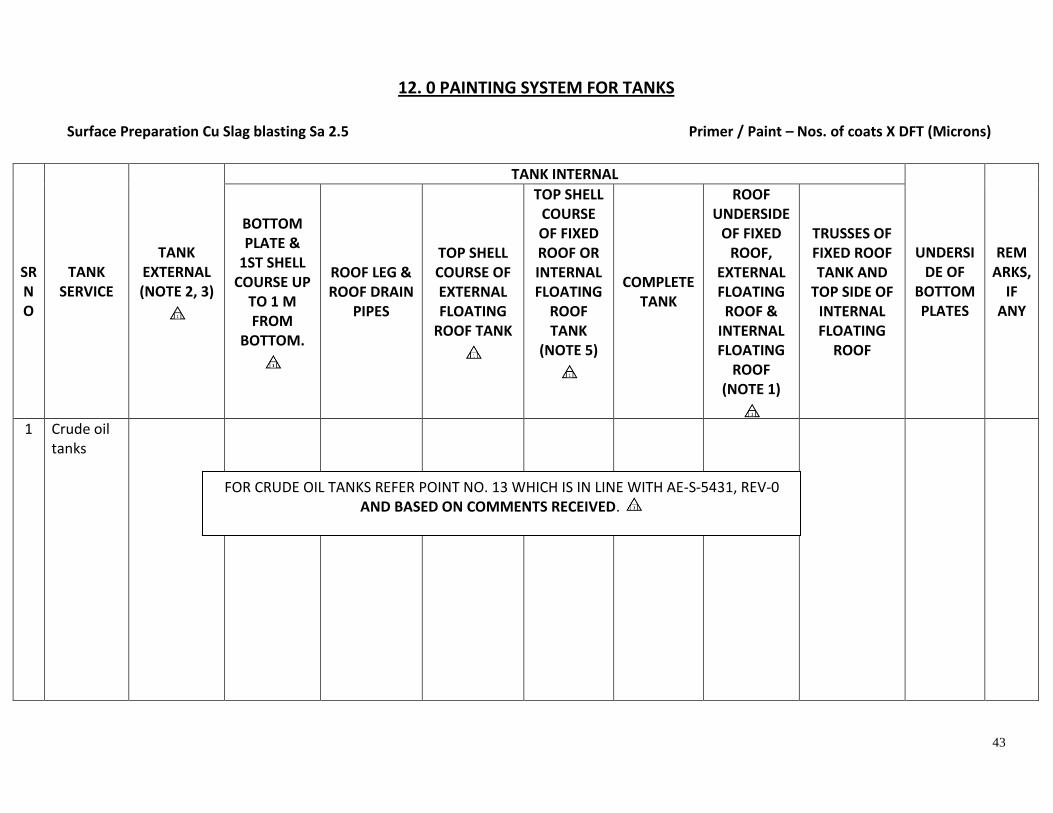
12. 0 PAINTING SYSTEM FOR TANKS
Surface Preparation Cu Slag blasting Sa 2.5 Primer / Paint – Nos. of coats X DFT (Microns)
SR NO
TANK SERVICE
TANK EXTERNAL (NOTE 2, 3)
TANK INTERNAL
UNDERSIDE OF
BOTTOM PLATES
REMARKS,
IF ANY
BOTTOM PLATE &
1ST SHELL COURSE UP
TO 1 M FROM
BOTTOM.
ROOF LEG & ROOF DRAIN
PIPES
TOP SHELL COURSE OF EXTERNAL FLOATING
ROOF TANK
TOP SHELL COURSE OF FIXED ROOF OR INTERNAL FLOATING
ROOF TANK
(NOTE 5)
COMPLETE TANK
ROOF UNDERSIDE
OF FIXED ROOF,
EXTERNAL FLOATING
ROOF & INTERNAL FLOATING
ROOF (NOTE 1)
TRUSSES OF FIXED ROOF TANK AND
TOP SIDE OF INTERNAL FLOATING
ROOF
1 Crude oil tanks
FOR CRUDE OIL TANKS REFER POINT NO. 13 WHICH IS IN LINE WITH AE-S-5431, REV-0 AND BASED ON COMMENTS RECEIVED.

44
SR NO
TANK SERVICE
TANK EXTERNAL (NOTE 2, 3)
TANK INTERNAL
UNDERSIDE OF
BOTTOM PLATES
REMARKS,
IF ANY
BOTTOM PLATE &
1ST SHELL COURSE UP
TO 1 M FROM
BOTTOM.
ROOF LEG & ROOF DRAIN
PIPES
TOP SHELL COURSE OF EXTERNAL FLOATING
ROOF TANK
TOP SHELL COURSE OF FIXED ROOF OR INTERNAL FLOATING
ROOF TANK
(NOTE 5)
COMPLETE TANK
ROOF UNDERSIDE
OF FIXED ROOF,
EXTERNAL FLOATING
ROOF & INTERNAL FLOATING
ROOF (NOTE 1)
TRUSSES OF FIXED ROOF TANK AND
TOP SIDE OF INTERNAL FLOATING
ROOF
2 Hexane , Motor spirit, Naphtha, IBP 60, Kerosene, Mineral turpentine, HSD, Flushing oil, LDO, ATF components (floating roof tank), SBP, Reformate
Amine adduct cured epoxy holding primer-1x60 Epoxy based Tank Liner-(amine cured) 2x120
Amine adduct cured epoxy holding primer-1x60 Epoxy Based Tank Liner- (amine cured) 2x120
Epoxy Coal Tar Paint-2x100
Amine adduct cured epoxy holding primer-1x60 Epoxy Based Tank Liner- (amine cured) 2x120
Amine adduct cured epoxy holding primer-1x60 Epoxy Based Tank Liner(amine cured) -2x120
Amine adduct cured epoxy holding primer-1x60 Epoxy Based Tank Liner(amine cured) -2x120
Epoxy Coal Tar Paint-2x100

45
SR NO
TANK SERVICE
TANK EXTERNAL (NOTE 2, 3)
TANK INTERNAL
UNDERSIDE OF
BOTTOM PLATES
REMARKS,
IF ANY
BOTTOM PLATE &
1ST SHELL COURSE UP
TO 1 M FROM
BOTTOM.
ROOF LEG & ROOF DRAIN
PIPES
TOP SHELL COURSE OF EXTERNAL FLOATING
ROOF TANK
TOP SHELL COURSE OF FIXED ROOF OR INTERNAL FLOATING
ROOF TANK
(NOTE 5)
COMPLETE TANK
ROOF UNDERSIDE
OF FIXED ROOF,
EXTERNAL FLOATING
ROOF & INTERNAL FLOATING
ROOF (NOTE 1)
TRUSSES OF FIXED ROOF TANK AND
TOP SIDE OF INTERNAL FLOATING
ROOF
3 ATF Batch (Fixed roof tanks)
Amine adduct cured epoxy holding primer-1x60 Epoxy Based Tank Liner-(amine cured)-2x120
Amine adduct cured epoxy holding primer-1x60 Epoxy Based Tank Liner-(amine cured)-2x120
Amine adduct cured epoxy holding primer-1x60 Epoxy Based Tank Liner-(amine cured)-2x120
Epoxy Coal Tar Paint-2x100

46
SR NO
TANK SERVICE
TANK EXTERNAL (NOTE 2, 3)
TANK INTERNAL
UNDERSIDE OF
BOTTOM PLATES
REMARKS,
IF ANY
BOTTOM PLATE &
1ST SHELL COURSE UP
TO 1 M FROM
BOTTOM.
ROOF LEG & ROOF DRAIN
PIPES
TOP SHELL COURSE OF EXTERNAL FLOATING
ROOF TANK
TOP SHELL COURSE OF FIXED ROOF OR INTERNAL FLOATING
ROOF TANK
(NOTE 5)
COMPLETE TANK
ROOF UNDERSIDE
OF FIXED ROOF,
EXTERNAL FLOATING
ROOF & INTERNAL FLOATING
ROOF (NOTE 1)
TRUSSES OF FIXED ROOF TANK AND
TOP SIDE OF INTERNAL FLOATING
ROOF
4 Slops and effluent tanks
Amine adduct cured epoxy holding primer-1x60 Epoxy Glass Flake (Amine Adduct)-1x200
Amine adduct cured epoxy holding primer-1x60 Epoxy Glass Flake (Amine Adduct)-1x200
Epoxy Coal Tar Paint-2x100
Amine adduct cured epoxy holding primer-1x70 Epoxy Glass Flake (Amine Adduct)-1x200
Amine adduct cured epoxy holding primer-1x60 Epoxy Glass Flake (Amine Adduct)-1x200
Amine adduct cured epoxy holding primer-1x60 Epoxy Glass Flake (Amine Adduct)-1x200
Epoxy Coal Tar Paint-2x100
5 Bitumen, SR
Two component high solid High temperature (up to 200 deg c )
Two component high solid High temperature (up to 200 deg c )
Two component high solid High temperature (up to 200 deg c )
Cold spray Aluminium OR Engineered

47
SR NO
TANK SERVICE
TANK EXTERNAL (NOTE 2, 3)
TANK INTERNAL
UNDERSIDE OF
BOTTOM PLATES
REMARKS,
IF ANY
BOTTOM PLATE &
1ST SHELL COURSE UP
TO 1 M FROM
BOTTOM.
ROOF LEG & ROOF DRAIN
PIPES
TOP SHELL COURSE OF EXTERNAL FLOATING
ROOF TANK
TOP SHELL COURSE OF FIXED ROOF OR INTERNAL FLOATING
ROOF TANK
(NOTE 5)
COMPLETE TANK
ROOF UNDERSIDE
OF FIXED ROOF,
EXTERNAL FLOATING
ROOF & INTERNAL FLOATING
ROOF (NOTE 1)
TRUSSES OF FIXED ROOF TANK AND
TOP SIDE OF INTERNAL FLOATING
ROOF
phenolic epoxy coating.-2x100 microns
phenolic epoxy coating.-2x100 microns
phenolic epoxy coating.-2x100 microns
Polysiloxane coating 2x125 microns
6 MTBE (Methyl-Tertiary Butyl Ether) tanks
Amine adduct cured epoxy holding primer-1x60; Epoxy Based Tank Liner-(amine cured)-2x120
Amine adduct cured epoxy holding primer-1x60; Epoxy Based Tank Liner-(amine cured)-2x120
Epoxy Coal Tar Paint-2x100
Amine adduct cured epoxy holding primer-1x60 Epoxy Based Tank Liner-(amine cured)-2x120
Amine adduct
cured epoxy holding
primer-1x60
Epoxy Based Tank Liner-
(amine cured)-2x120
Amine adduct cured epoxy
holding primer-1x60
Epoxy Based Tank Liner-
(amine cured)-2x120
Epoxy Coal Tar Paint-2x100

48
SR NO
TANK SERVICE
TANK EXTERNAL (NOTE 2, 3)
TANK INTERNAL
UNDERSIDE OF
BOTTOM PLATES
REMARKS,
IF ANY
BOTTOM PLATE &
1ST SHELL COURSE UP
TO 1 M FROM
BOTTOM.
ROOF LEG & ROOF DRAIN
PIPES
TOP SHELL COURSE OF EXTERNAL FLOATING
ROOF TANK
TOP SHELL COURSE OF FIXED ROOF OR INTERNAL FLOATING
ROOF TANK
(NOTE 5)
COMPLETE TANK
ROOF UNDERSIDE
OF FIXED ROOF,
EXTERNAL FLOATING
ROOF & INTERNAL FLOATING
ROOF (NOTE 1)
TRUSSES OF FIXED ROOF TANK AND
TOP SIDE OF INTERNAL FLOATING
ROOF
7 Caustic tanks
Amine adduct cured epoxy holding primer-1x60 Epoxy Based Tank Liner-(amine cured)-2x120
Amine adduct cured epoxy holding primer-1x60 Epoxy Based Tank Liner-(amine cured)-2x120
Amine adduct cured epoxy holding primer-1x60 Epoxy Based Tank Liner-(amine cured)-2x120
Epoxy Coal Tar Paint-2x100
8 LR, Waxy, HGO, Fuel oil, cycle oil, LSHS, Lube waxy
Amine adduct
cured epoxy holding
primer-1x60
Two
Amine adduct cured epoxy holding primer-1x60
Amine adduct cured epoxy holding primer-1x60 Two
Amine adduct cured epoxy holding primer-1x60 Two component
Epoxy Coal Tar Paint-2x100

49
SR NO
TANK SERVICE
TANK EXTERNAL (NOTE 2, 3)
TANK INTERNAL
UNDERSIDE OF
BOTTOM PLATES
REMARKS,
IF ANY
BOTTOM PLATE &
1ST SHELL COURSE UP
TO 1 M FROM
BOTTOM.
ROOF LEG & ROOF DRAIN
PIPES
TOP SHELL COURSE OF EXTERNAL FLOATING
ROOF TANK
TOP SHELL COURSE OF FIXED ROOF OR INTERNAL FLOATING
ROOF TANK
(NOTE 5)
COMPLETE TANK
ROOF UNDERSIDE
OF FIXED ROOF,
EXTERNAL FLOATING
ROOF & INTERNAL FLOATING
ROOF (NOTE 1)
TRUSSES OF FIXED ROOF TANK AND
TOP SIDE OF INTERNAL FLOATING
ROOF
tanks (operating immersed heat temperature 120 deg C)
component high solid
High temperature phenolic
epoxy coating.-
2x100 microns
Two component high solid High temperature phenolic epoxy coating.-2x100 mic.
component high solid High temperature phenolic epoxy coating.-2x100 microns
high solid High temperature phenolic epoxy coating.-2x100 microns
9 Benzene, Toluene, Methanol, Extract,
Amine adduct cured epoxy holding primer-1x60
Amine adduct cured epoxy holding primer-
Amine adduct cured epoxy holding primer-1x60
Amine adduct cured epoxy holding primer-1x60 Two
Epoxy Coal Tar Paint-2x100

50
SR NO
TANK SERVICE
TANK EXTERNAL (NOTE 2, 3)
TANK INTERNAL
UNDERSIDE OF
BOTTOM PLATES
REMARKS,
IF ANY
BOTTOM PLATE &
1ST SHELL COURSE UP
TO 1 M FROM
BOTTOM.
ROOF LEG & ROOF DRAIN
PIPES
TOP SHELL COURSE OF EXTERNAL FLOATING
ROOF TANK
TOP SHELL COURSE OF FIXED ROOF OR INTERNAL FLOATING
ROOF TANK
(NOTE 5)
COMPLETE TANK
ROOF UNDERSIDE
OF FIXED ROOF,
EXTERNAL FLOATING
ROOF & INTERNAL FLOATING
ROOF (NOTE 1)
TRUSSES OF FIXED ROOF TANK AND
TOP SIDE OF INTERNAL FLOATING
ROOF
Two component high solid High temperature phenolic epoxy coating.-2x100 microns
1x60 Two component high solid High phenolic epoxy coating.-2x100 microns
Two component high solid High phenolic epoxy coating.-2x100 microns
component high solid High temperature phenolic epoxy coating.-2x100 microns
10 Lube oil tanks (Non-waxy tanks)
Amine adduct cured epoxy holding primer-1x60 Epoxy Based Tank Liner-(amine cured)-
Amine adduct
cured epoxy holding
primer-1x60 Epoxy Based Tank Liner-
(amine cured)-2x120
Amine adduct
cured epoxy holding
primer-1x60 Epoxy Based Tank Liner-
(amine cured)-
Amine adduct cured epoxy
holding primer-1x60 Epoxy Based Tank Liner-
(amine cured)-2x120
Epoxy Coal Tar Paint-2x100

51
SR NO
TANK SERVICE
TANK EXTERNAL (NOTE 2, 3)
TANK INTERNAL
UNDERSIDE OF
BOTTOM PLATES
REMARKS,
IF ANY
BOTTOM PLATE &
1ST SHELL COURSE UP
TO 1 M FROM
BOTTOM.
ROOF LEG & ROOF DRAIN
PIPES
TOP SHELL COURSE OF EXTERNAL FLOATING
ROOF TANK
TOP SHELL COURSE OF FIXED ROOF OR INTERNAL FLOATING
ROOF TANK
(NOTE 5)
COMPLETE TANK
ROOF UNDERSIDE
OF FIXED ROOF,
EXTERNAL FLOATING
ROOF & INTERNAL FLOATING
ROOF (NOTE 1)
TRUSSES OF FIXED ROOF TANK AND
TOP SIDE OF INTERNAL FLOATING
ROOF
2x120
2x120
11 Drinking water, DM water, Raw water, Salt water
Amine adduct cured
epoxy holding
primer-1x60 Solvent free
epoxy 1X300-(amine cured)
(Portable water Cert.
Amine adduct cured epoxy
holding primer-
1x60 Solvent
free epoxy 1X300-(amine cured)
(Portable water Cert.
Amine adduct
cured epoxy holding
primer-1x60 Solvent free
epoxy 1X300-(amine cured)
(Portable water Cert.
Amine adduct cured epoxy
holding primer-1x60 Solvent free
epoxy 1X300-(amine cured)
(Portable water Cert.
Epoxy Coal Tar Paint-2x100

52
SR NO
TANK SERVICE
TANK EXTERNAL (NOTE 2, 3)
TANK INTERNAL
UNDERSIDE OF
BOTTOM PLATES
REMARKS,
IF ANY
BOTTOM PLATE &
1ST SHELL COURSE UP
TO 1 M FROM
BOTTOM.
ROOF LEG & ROOF DRAIN
PIPES
TOP SHELL COURSE OF EXTERNAL FLOATING
ROOF TANK
TOP SHELL COURSE OF FIXED ROOF OR INTERNAL FLOATING
ROOF TANK
(NOTE 5)
COMPLETE TANK
ROOF UNDERSIDE
OF FIXED ROOF,
EXTERNAL FLOATING
ROOF & INTERNAL FLOATING
ROOF (NOTE 1)
TRUSSES OF FIXED ROOF TANK AND
TOP SIDE OF INTERNAL FLOATING
ROOF
12 Sulfolene Amine adduct cured epoxy
holding primer-1x60.
Amine adduct
cured HB epoxy -2x120
Amine adduct
cured epoxy holding primer-1x60.
Amine adduct
cured HB epoxy -2x120
Amine adduct cured epoxy
holding primer-1x60.
Amine adduct
cured HB epoxy -2x120
Epoxy Coal Tar Paint-2x100
Note: 1) Carbon steel external and internal floating roof underside paint shall cover all wetted surfaces.
2) Vertical band on shell external at gauging pole shall have top coat in black colour.
3) External painting other than crude tanks:

53
a) FOR UN-INSULATED TANKS EXTERNAL SURFACES - NEW OR HEAVILY CORRODED; TOP SIDE (NON-WTTED SURFACES) OF EXTERNAL FLOATING
ROOF. SURFACE PREPARATION TO SA 2.5.
i) One coat of inorganic zinc ethyl silicate 1x70 microns
ii) Two coat of epoxy high solids MIO 2 X 125 microns DFT.
iii) Two coats of aliphatic acrylic polyurethane - 2 x 40 microns DFT.
b) FOR UN-INSULATED TANK EXTERNAL OF MODERATELY CORRODED OLD TANKS. SURFACE PREPARATION MANUAL CLEANING TO ST 2 OR POWER
TOOL CLEANING TO ST3.
i) Tank bottom shell course shall be painted with 2x100 microns Coal Tar Epoxy paint.
ii) Other than bottom shells, Epoxy Red Oxide Zinc Phosphate Primer-1X60 and Oil Based Aluminum Paint-2 X 20.
c) FOR INSULATED TANK EXTERNAL OF NEW TANKS OR HEAVILY CORRODED TANKS. SURFACE PREPARATION TO SA 2.5.
i) Two component high solid High temperature (up to 200deg c dry heat) Phenolic CUI (corrosion under insulation) epoxy coating
2 X 125 microns.
d) FOR INSULATED TANK EXTERNAL OF MODERATELY CORRODED OLD TANKS. SURFACE PREPARATION MANUAL CLEANING TO ST 2 OR POWER TOOL
CLEANING TO ST3.
i) Zinc dust graphite-2 x40 microns.
4) All carbon steel pontoons internal surfaces of external floating roof and internal floating roof tanks other than crude tanks:
a) Epoxy Red Oxide Zinc Phosphate Primer-1X60 microns.
b) Oil Based Aluminum Paint-2X20 microns.
5) External floating roof tanks top shell internal painting shall extend up to 100 mm above top of shunt of secondary seal marked at safe filling
height during hydro test.
6) Aluminum surfaces shall not to be painted.
7) Before changing of tank service resistivity of the painting system to be verified.
8) In tank history details of paint manufactures with brand name to be mentioned. These would facilitate defects observations and would also
be basis for evaluation of the painting contractor /paint system and manufacturer for future works.

54
9) For all internal lining / internal painting works, manufacturer’s laboratory test statement / Laboratory Paint performance certificates to be
submitted by paint manufacturers & checked apart from material test certificates for specified services at operating temperature and
condition. Material shall be procured from only those approved manufacturers who will meet the above stated criteria.
10) For details of tanks internal painting refer Annexure - H

55
13. CRUDE OIL TANKS PAINTINGS
13.1 Scope
This standard exclusively covers the painting of crude oil storage tanks in BPCL Refineries. This standard has been derived from existing AE-S-5430, Rev. 0 and painting practices being followed at BPCL-KR. Intent of this standard is to cover a common painting practice across all BPCL group of Refineries.
13.2 Tank operating condtions
Operating temperature : Not above 65 degree celsius.
Operating pressure : Ambient.
13.3 Surface preparation
The purpose of surface preparation is to create a continuous highly adherent, homogeneous and defect free paint film with an even thickness over the tank surfaces. For new painting, all the internal & external surfaces shall be blasted to achieve the surface profile as given in Annexure – A. Light shades and streaks are not allowed. When steel shot is used, it shall be used together with steel grit. The purpose of surface preparation is to create a continuous highly adherent, homogeneous and defect free paint film with an even thickness over the tank surface. Compressed air used shall be free of moisture and oil. Adequate separators and traps shall be provided, installed in the coolest part of the system. The presence of oil and water shall be determined at least two (2) times per eight hours and following every compressor start-up. The air discharge temperature shall not exceed 100 °C. The blasting nozzles should be venturi style with tungsten carbide or boron carbide as the materials for liners. Blasting nozzles shall be replaced when the specified minimum blast pressure, surface cleanliness and surface roughness can no longer be achieved. Blasting equipment and the equipment being blasted shall be properly earthed to prevent the occurrence of electrostatic discharges. If possible vacuum collector shall be installed for collecting the abrasives for recycling. Recycled shot shall be used only after ensuring that it is clean enough to provide the minimum surface preparation mentioned above.
When working in confined spaces, adequate ventilation and intrinsically safe lighting shall be used. As a minimum, ventilation shall ensure sufficient air changes such that the threshold limit value (TLV) of the various coating materials in use shall not be exceeded. Access for coating work should be constructed so as to provide easy and sufficient access for surface preparation, painting and inspection of all surfaces
13.4 Recommended environment conditions for Paint Application
For all cases, paint manufacturer guidelines shall be followed. Following restrictions are given as recommended practices:

56
13.4.1 Coating application shall not be permitted in the following conditions.
4.1.1 During fog, mist or rain. 4.1.2 When the relative humidity is 85 percent or above. 4.1.3 When the steel surface temperature and/or ambient temperature is below
10°C (50°F) . 4.1.4 When the steel surface temperature and/or ambient temperature is above
50°C (120°F). 4.1.5 When the steel surface temperature is less than 3°C (5°F) above the dew
point.
13.4.2 For all internal painting work, the dehumidification of the surrounding air dew point shall be maintained 5 degree celsius below the prevailing surface temperature. The relative humidity shall be maintained not more than 45% from preparation to curing of coatings.
13.4.3 The measurement of the following shall ensured prior to start of work and shall be
done every three hours for the entire duration of the painting work and shall extend till the paint is dried and cured.
4.3.1 Relative Humidity (RH).
4.3.2 Ambient air temperature.
4.3.3 Surface temperature of the object being painted.
4.3.4 Air temperature at surrounding of the painting.
4.3.5 Air flow
13.4.4 There shall be no welding activity or radiography testing on the shell during and after installation of coating system.
13.4.5 Humidity and dew point readings shall be taken with a sling Psychrometric meter and calculated using psychrometric tables.
13.4.6 Coatings shall not be applied before the surface has been inspected and the
preparatory work approved. 13.4.7 All edges shall be ground to a minimum radius of 3.2 mm. Flame cut areas and weld
spatter shall have been ground flush. All rough welds shall be ground to remove sharp edges and other such irregularities. The amount of grinding performed shall be judicious and performed only to the extent necessary to prepare the weld surface and surrounding metal surfaces in accordance with the specification. Over grinding, which would result in decreasing the wall thickness or the integrity of the weld beyond the limitations imposed by good welding practices, applicable welding codes, or tank or vessel ratings, shall be avoided. All weld spatter and arc strikes must be removed. (Refer NACE SP 0178).

57
13.4.8 Salt water spray areas shall require fresh water blasting or fresh water (Max.
Chloride content 50 ppm) mopping to remove the salts deposited on metal surface before application of primer. Mopping can be repeated before application of other coats to remove salts deposited on previous coats, if such deposits are suspected.
13.4.9 Blast cleaned steel surfaces shall not be touched by bare hands
13.4.10 If the surface being cleaned is adjacent to a coated surface, the blast cleaning shall cut in to the coated surface by at least 50 mm. The edges of the existing coating system shall be feathered. The remainder of the existing coated surface shall be properly protected with shields or screens to prevent any over blast damage.
13.4.11 To prevent dust and abrasive contamination, blast cleaning shall not be carried out adjacent to painting operations or wet (painted) surfaces
13.5 Mixing and Painting
13.5.1 Mixing & Thinning
All paint spraying equipment, including mixers, shall be thoroughly cleaned before mixing of new materials. All coating materials shall be mixed and thoroughly stirred in accordance with the instructions of the paint Manufacturer. Sufficient agitation to maintain good mixing shall be applied until the product is used. If air is entrapped in the product during mixing/stirring, sufficient time should be allowed for the air bubbles to escape before application.
13.5.2 Application of paint/primer:
5.2.1 Blast cleaned surface shall be coated with one complete application of primer as soon as practicable but in no case later than 4 hrs. the same day or as per the time frame stipulated in the technical data sheet of the paint, whichever is earlier.
5.2.2 To the maximum extent practicable, each coat of material shall be applied as a continuous film uniform thickness free of porous. Any spots or areas missed in application shall be recoated and permitted to dry before the next coat is applied. Applied paint should have the desired wet film thickness.
5.2.3 No coat shall be applied until the preceding coat has dried and cured as
recommended by Paint Manufacturer. Next coat shall be applied within the time stipulated by the paint manufacturer. Before over coating, over-runs, drips and smears shall be removed and any coating damage or imperfection shall be repaired. The material shall be considered dry for re-coating when another coat can be applied without the development of any film irregularities such as lifting or loss of adhesion of undercoats. Drying time of the applied coat should not exceed maximum specified for it as a first coat; if it exceeds the paint material has possibly deteriorated or mixing is faulty.
5.2.4 No paint shall be force dried under conditions, which will cause cracking, wrinkling,
blistering formation of pores, or detrimentally affect the conditions of the paint. No

58
drier shall be added to paint on the job unless specifically called for in the manufacturer's specification for the paint. Paint shall be protected from rain, condensation and contamination until dry.
5.2.5 All paints and painting materials shall be stored only in rooms to be arranged by contractor and approved by Engineer-in-charge for the purpose. All necessary precautions shall be taken to prevent fire.
5.2.6 Surface preparation and paint application shall be done in presence of Manufacturer’s representative. Manufacturer’s representative shall have necessary certification from agency like NACE to supervise and ensure the quality of paint applied.
5.2.7 All personnel shall be provided with personnel protection, e.g. protective clothing,
safety glasses, safety shoes, hard hats, goggles, respirators, earplugs, fresh air-fed hood and any other necessary safety equipment. All safety equipment shall be maintained in a good working condition. Warning signs shall be prominently displayed at all access points to areas where abrasive blasting and painting is in progress.
5.2.8 The Contractor shall protect all equipment, structures and any other areas from
mechanical damage, environmental damage, blockage or obstruction and damage caused by over blasting, dripping paint, paint splashes and overspray.
5.2.9 To minimise the risk of damage, no lifting, transportation, erection or fabrication
operations shall be done before the paint has been fully dried and/or cured.
5.2.10 Abrasive blast cleaning and coating operations should be carried out during daylight hours. However, grit blasting and coating may be carried out at night providing the lighting and environmental conditions are acceptable. Minimum lighting requirements for abrasive blasting, painting and inspection are 500 lux.
5.2.11 For internal tank coatings and the external coatings of buried or immersed
equipment and structures, pinhole testing for electrically non-conductive coatings shall be carried out in accordance with NACE SP0188. The high voltage technique shall be used; nominally set at 5 V/µbased on DFT, or as agreed with the paint Manufacturer but not exceeding 25 kV in total. For coating thickness < 500 µ DFT, the low voltage wet sponge technique shall be used.
13.5.3 Spray application
Spraying is the required method of application. The painting Contractor shall supply the required range of spray tips, sizes and fan angles for the work being undertaken. The spray pressure shall be uniform and the spray pattern smooth.
13.5.4 Brush application

59
Brush application may be done for Maintenance operations, in those cases where spray application may affect other plant, equipment, property or personnel in or near the work site. Where the coating product is specified as only being suitable for brush application. Manufacturer shall confirm in writing that paint is suitable for brush application and will able to meet the guarantee period. Brush application shall be done only with concurrence of Engineer in charge. Coatings applied by brush shall be smooth and even
13.5.5 Roller application
Roller application shall only be allowed for steel floors and for panels and equipment inside climate-controlled areas. Rollers shall be of good quality to ensure uniformity of the applied coating.
13.5.6 Stripe coat
Before spray application of each coat, irregular surfaces such as sharp edges, welds, small brackets, interstices etc. shall be stripe-coated, usually by brush, to ensure the specified film thickness is provided..
13.5.7 Repair of coating defects
Damaged areas, defects in the coating system such as over-runs, drips and smears that have to be removed or areas with inadequate dry film coating thickness shall be re-cleaned. The re-cleaning shall carry over on to the sound coating for not less than 50 mm all round, the edges of which shall be feathered. After the surface cleaning, the specified coating system shall be re-applied. Any additional coats shall blend in with the final coating at adjoining areas. Paint Manufacturers shall be consulted if the existing coating requires abrading before over-coating to obtain good bonding.
13.5.8 Only thinners specified by the paint Manufacturer shall be used
13.6 Paint Procurement
Painting Contractor shall procure paint material from BPCL approved manufacturers only.
13.7 Inspection and testing
13.7.1 Refer section 12 for testing of paint material
13.7.2 Minimum suggested stages of inspection shall be:
a. Surface Preparation b. Primer application c. Each coat of paint

60
13.7.3 All defects noticed during stages of inspection, shall be rectified free of cost by the
contractor. All records shall be kept by the contractor.
13.7.4 Wet film thickness measurements shall be made throughout the course of painting in order to ascertain the adequacy and uniformity of thickness. The readings shall be taken at least one every ten (10) square metres.
13.7.5 Dry film thickness shall be taken on each coat after drying and curing of the coat. Dry film
thickness (DFT) readings shall be taken using a non-destructive dry film thickness instrument capable of storing the readings. Sufficient readings shall be taken covering each coat prior to application of the following coat to ensure the correct required DFT.
13.7.6 The DFT indicated against each system shall be obtained by applying one or more coat of
the paint based on paint properties. The Contractor is responsible to obtain the indicated DFT as per painting system specification.
13.7.7 DFT meter used shall be calibrated before each inspection and shall be witnessed by the
Inspector. It is the duty of the Inspector to satisfy him/herself with the performance of the DFT meter.
13.7.8 Criteria for acceptance of painting work shall be in accordance with table – 2.
TABLE - 2
Test Standard Frequency Acceptance criteria
Surface
cleanliness
ISO 8501-1 One per ten (10)
square meters
Sa 2 ½
Surface Profile ISO 8503-2 One per ten (10)
square meters
As per coating procedure / data
sheet
Total Soluble
salt
contamination
ISO 8502-9 One per twenty (20)
square meters or
minimum 5 tests
whichever is more.
<5g/cm2
Dust ISO 8502-3 One per ten (10)
square meters
Rating 2 or better
Adhesion ISO 4624 One pretest panel,
per shift
5 MPa
Holiday
Detection
NACE SP0188 100% of surface Zero defects
Dry Film
Thickness
SSPC PA-2 As per Annexure - F Shall not be less than 80 % and
more than 120 % of the
Specified dry film thickness.

61
Test Standard Frequency Acceptance criteria
(DFT).
Wet Film
Thickness
ISO 2802 One per ten (10)
square meters
Consistent with providing
required DFT
13.8 Painting Contrator’s Responsibility
13.8.1 Contractor shall mobilize the adequate capacity dehumidification unit at site for all internal painting work, if required. The surrounding air dew point shall be maintained 5 degree celsius below the prevailing surface temperature. The relative humidity shall be maintained not more than 45% from preparation to curing of coatings.
13.8.2 The contractor shall ensure proper functioning of the dehumidification unit, measuring RH and temperature , measuring air flows and maintained 24 hours till coating work is completed in the tank.
13.8.3 All paints and consumables for a particular tank painting work shall be sourced from one manufacturer only to have desired paint performance, guarantee and single point responsibility.
13.8.4 Painting contractor shall deploy adequate number of NACE CIP Level 2 qualified coating
Inspectors to supervise, monitor, inspect & control entire painting process right from the surface preparation, storage, handling, mixing and application on substrate of the painting/coating and to ensure the compliance of this specification.These qualified painting inspectors will report to and shall get guided by BPCL Inspection Dept.
13.8.5 Each contractor shall possess relevant standards and deploy all inspection tool/instrument
to carry out the all above inspection and testing as per relevant standard.
13.8.6 Organising of testing all the painting parameters , supply of all the testing instruments, consumables for testing each parameter as defined in clause 7.10 above , including getting accepted by BPCL, shall be the responsibility of painting contractor.
13.8.7 The Inspection test plan which will be mandatory part of the contract shall be prepared by
the above qualified coating inspector and get it approved by BPCL inspection department. The Contractor’s qualified coating inspector and BPCL shall sign an inspection report as per approved inspection test plan.
13.8.8 The report shall consist, as a minimum, of the following in addition to the inspection
parameters and acceptable criteria : 8.8.1 Names of the applicator and the responsible personnel. 8.8.2 Dates when work was carried out. 8.8.3 Paint testing parameters tested

62
8.8.4 Equipment and techniques used. 8.8.5 Type and calibration of instruments used. 8.8.6 Weather and ambient conditions.
13.9 Frequency and Guarantee of painting
13.9.1 Frequency of Crude oil tanks Painting system for both internal and external painting shall be once in 10 years.
13.9.2 Painting Contractor shall furnish Guarantee for minimum 10 years for both internal and
external painting with shot blasting as per Annexure – B, C, D & E.
13.9.3 BPCL reserves the right to invoke the gurantees in case contractor (paint applicator) or
contractor fail to repair the paint failed area within reasonable time.
13.10 Painting system
13.10.1 The painting system shall be as mentioned in Annexure – A. 13.10.2 The bands and colour coding shall be proved as per Specific Refinery Location practices . 13.10.3 No painting is considered for roof legs. Roof legs to be hot dip galvanized. Schedule 80
pipes to be used for both roof legs and sleeves. The sufficient clearance shall be ensured between sleeves and roof legs.
13.11 SIGN WRITING
All painting work information shall be mentioned (sign writing) with date of completion on Tank
shell as per Engineer-in-charge instructions.
13.12 INSPECTION AND TESTING OF PAINTING MATERIAL
13.12.1 All the procured paint material along with batch/test certificates shall be offered for BPCL inspection for approval. Remaining Shelf life shall be at least 90% of the total duration at the inspection above.
13.12.2 All paint materials shall be accompanied by Manufacturer Test Certificate. Inspection Engineer at his discretion may test paint formulations, if required.

63
ANNEXURE – A
SR. NO.
SURFACES SURFACE PREPARATION
SURFACE PROFILE
PRIMER FINISH COAT TOTAL DFT,
MICRONS
1 Bottom plate under side (soil
side)
Blast cleaning with grit and shot to Sa 2.5
Profile of 40-70
microns
Not applicable Polyamine cured epoxy-
2x150 microns DFT.
OR Epoxy Coal Tar Paint-
2x100
300
2 a) Bottom plate top side (oil side).
b) Bottom first shell internal up to 1.0 m from bottom.
c) Floating roof underside (oil side)
d) Pontoon rims external (oil side)
e) Roof legs
Blast cleaning with grit and shot to Sa 2.5
Sharp angular
profile of 40 -70
microns
Amine adduct cured epoxy - 1x75 microns
DFT.
Polyamine adduct cured solvent free
epoxy - 2x275 microns DFT.
625
OR Phenolic epoxy
novolac holding primer - 1x75 microns
DFT.
OR Phenolic
epoxy novolac
solvent free epoxy- 1x550 microns DFT.
3 Top shell internal
100 mm above top of shunt of secondary seal marked at safe filling height during hydro test.
Blast cleaning with grit and shot to Sa 2.5
40 microns
Epoxy Coal Tar Paint-1x100
microns. --------------------
OR One coat of
inorganic zinc ethyl silicate (VS 65%; 85%
zinc on dry film minimum) –
1x70 microns DFT.
Epoxy Coal Tar Paint-1x100
microns -----------------
OR 1) Two coat
of epoxy high solids MIO (minimum 50 % lamellar MIO on dry film and
200
_________
OR
350

64
SR. NO.
SURFACES SURFACE PREPARATION
SURFACE PROFILE
PRIMER FINISH COAT TOTAL DFT,
MICRONS
vol solids -80%). Mist coat & full coat 100 microns plus one coat 100 microns DFT.
2) Two coats of aliphatic acrylic polyurethane with minimum 55% vol solids - 2 x 40 microns DFT. (Black color)
OR 1) Two coats of modified epoxy (vol
solids -80%). Mist coat & full coat 100 microns plus one coat 100 microns DFT. 2)Two coats of aliphatic acrylic polyurethane with minimum 55% vol solids - 2 x 40 microns DFT. (Black color).

65
SR. NO.
SURFACES SURFACE PREPARATION
SURFACE PROFILE
PRIMER FINISH COAT TOTAL DFT,
MICRONS
4 a) Bottom shell
external surface.
b) Vertical gauging band.
Cu-Slag to Sa 2.5
40 microns
One coat of inorganic zinc ethyl silicate (VS 65%; 85%
zinc on dry film minimum) –
1x70 microns DFT.
1) Two coat of epoxy high solids MIO (minimum 50 % lamellar MIO on dry film and vol solids -80%). Mist coat & full coat 125 microns plus one coat 125 microns DFT.
2) Two coats of aliphatic acrylic polyurethane with minimum 55% vol solids - 2 x 40 microns DFT. (Black color)
OR 1) Two coats of modified epoxy (vol
solids -80%). Mist coat & full coat 125 microns plus one coat 125 microns DFT. 2)Two coats of aliphatic
400

66
SR. NO.
SURFACES SURFACE PREPARATION
SURFACE PROFILE
PRIMER FINISH COAT TOTAL DFT,
MICRONS
acrylic polyurethane with minimum 55% vol solids - 2 x 40 microns DFT. (Black color).
5 a) Shell external surface other than bottom shell and vertical gauge band. __________
b) Roof deck plates top surface
Cu-Slag to Sa 2.5
____________ Blast cleaning with grit and shot to Sa 2.5
40 microns
One coat of inorganic zinc ethyl silicate (VS 65%; 85%
zinc on dry film minimum) –
1x70 microns DFT.
1) Two coat of epoxy high solids MIO (minimum 50 % lamellar MIO on dry film and vol solids -80%). Mist coat & full coat 125 microns plus one coat 125 microns DFT.
2) Two coats of aliphatic acrylic polyurethane with minimum 55% vol solids - 2 x 40 microns DFT. (Aluminium finish, RAL 9006 white aluminium)
400

67
SR. NO.
SURFACES SURFACE PREPARATION
SURFACE PROFILE
PRIMER FINISH COAT TOTAL DFT,
MICRONS
OR
1) Two coats of modified epoxy (vol
solids -80%). Mist coat & full coat 125 microns plus one coat 125 microns DFT. 2)Two coats of aliphatic acrylic polyurethane with minimum 55% vol solids - 2 x 40 microns DFT. (Aluminium finish, RAL 9006 white aluminium ).
6 Pontoon inside surface
SSPC – SP2/ST2
Not applicable
Not applicable Epoxy Red Oxide Zinc Phosphate Primer-1X60 microns. Oil Based Aluminum Paint-2X20 microns.
100
7 Color band Light surface preparation with emery paper 200 no.
on painted surface.
Not applicable Two coats of aliphatic acrylic
polyurethane with
minimum 55% vol solids
2 x 30 mic.
60 (above painted surface.)

68
SR. NO.
SURFACES SURFACE PREPARATION
SURFACE PROFILE
PRIMER FINISH COAT TOTAL DFT,
MICRONS
8 Logo/ sign writing
Light surface preparation with emery paper 200 no.
on painted surface.
Not applicable Alkyd base enamel paint in two coats
of 30 microns per coat total
two coats.
60 (above painted surface.)
Note: 1) Stripe coat is must for weld area, edges and corners. 2) Over zinc silicate, intermediate coat to be applied in mist coat and full coat technique. 3) In PU paint of silver shade, total thickness to be build in two coats.
4) For PU paint QUVA 340 requirement of 80 % gloss retention after 3000 hrs. 5) All sharp edges to be grinded well before painting.
6) Pitted area having width greater than 2mm or depth greater than 5 mm to be filled with solvent less polyamine adduct cured epoxy.

69
ANNEXURE – B
PAINT PERFORMANCE GUARANTEE REQUIREMENTS
a) In order to ensure that BPCL gets proper value for the amount invested in painting system, all endeavour should be to entrust the painting job in totality to the paint manufacturers/ paint applicators approved by paint manufacturer..
b) The contractor/ paint manufacturers shall guarantee that the chemical and physical properties of
paint materials used are in accordance with specifications contained herein.
c) Any defects that occur during the guaranteed life for the paint system either due to improper paint materials used or due to faulty application shall be rectified by the paint manufacturer/contractor at no extra cost to BPCL.
d) For surfaces painted after shot and grit blasting - The bank guarantee for initial 2 years from
the date of completion of the job and 8 years Corporate guarantee in the required format (enclosed) for the tank painting system shall be submitted by paint manufacturer & applicator either prior to taking up the painting job or after the completion of painting job subject to release of payment only after the submission of this guarantee.
e) For surfaces painted after Cu Slag blasting - The bank guarantee for initial 2 years from the date of completion of the job and 3 years Corporate guarantee in the required format (enclosed) for the tank painting system shall be submitted by paint manufacturer & applicator either prior to taking up the painting job or after the completion of painting job subject to release of payment only after the submission of this guarantee.
f) The performance guarantee consists of 2 years bank guarantee for an equivalent value of 20% and
balance 3 years and 8 years against corporate guarantee.

70
ANNEXURE – C
1. All the guarantees should be submitted to BPCL in the Standard format given in this specification.
The guarantee will be two components.
i. The performance guarantee shall be given by the painting contractor for the period of two years. The retention period is for two years from the date of completion. Hence, Bank guarantee for 2 years for an amount equal to 20 % of contract value of painting work to be submitted to BPCL.
ii. Corporate guarantee for balance 8 years for surfaces painted after Shot and grit blasting
and 3 years for surfaces painted after Cu Slag blasting. The painting contractor and paint manufacturer should have proper agreements and both should sign the corporate guarantee.
2. During the guarantee period, the paint supplier will carry out joint inspection every six months for
first two years and every one year after this along with BPCL engineers. All repairs during the
guarantee period will be done by paint manufacturers at their cost. The extent of corrosion will be
monitored during joint inspections by paint supplier and BPCL engineer.
3. High pressure water washing for tank internal to be carried out .The water shall be potable.
4. Dehumidification system shall be used for internal painting of tanks, if required. Paint
Manufacturer shall decide on whether dehumidifier is there based on the atmospheric condition..

71
ANNEXURE – D
PROFORMA OF BANK GUARANTEE
(PERFORMANCE)
Bharat Petroleum Corporation Limited
Dear Sirs,
In consideration of the Bharat Petroleum Corporation Limited (hereinafter called ‘the
Company’ which expression shall include its successors and assigns) having awarded to
M/s. (Name)_____________________________________________________________
(Constitution)_________________________________________________(address)
_____ _______________________________________________________herein after referred to
as ‘ The Vendor’ which expression shall wherever the subject or context so permits include its
successors and assigns) a supply contract in terms inter alia, of the Company's Letter no.
________________ dated_____________ and the General Purchase Conditions of the Company
and upon the conditions of Vendor’s furnishing security for the performance of Vendor's
obligations and / or discharge of the Vendor’s liability under and/or in connection with the said
supply contract up to a sum of (in figures) _____________________(in words)
_______________________________________only amounting to 20% (twenty percent) of the
total contract value.
We, (name) _____________________________ (constitution)_________________
_________________________________(hereinafter called ‘the Bank’ which expression shall
include its successors and assigns) hereby jointly and severally undertake and guarantee to pay to
the Company in (Currency) forthwith on demand in writing and without protest or demur of any
and all moneys anywise payable by the Supplier to the Company under, in respect of or in
connection with the said supply contract inclusive of all the Company’s losses and expenses and
other moneys anywise payable in respect of the above as specified in any notice of demand made
by the Company to the Bank with reference to this Guarantee upon an aggregate limit of Rs. (in
figures)______________________(in words) ______________________________ only).
And the Bank hereby agrees with the Company that:
a) This Guarantee I Undertake shall be a continuing Guarantee and shall remain valid and irrevocable
for all claims 'of the Company and liabilities of the Vendor arising upto and until midnight of
_______________________________________.

72
b) The Guarantee / Undertaking shall be in addition to any other guarantee or security of whatsoever
that the Company may now or at any time otherwise have in relation to the Vendor's obligations /
liabilities under and / or in connection with the said supply contract, and the Company shall have
full authority to take recourse to or reinforce this security in preference to the other security(ies) at
its sole discretion, and no failure on the part of the Company in enforcing or requiring enforcement
of any other security shall have the effect of releasing the Bank from its full liability hereunder.
c) The Company shall be at liability without reference to the Bank and without effecting the full liability
of the Bank hereunder to take any other security in respect of the Vendor's obligations and / or
liabilities under or in connection with the said supply contract and to vary the terms vis-a-vis the
vendor of the said supply contract or to grant time and / or indulgence to the Vendor or to reduce
or to increase or otherwise vary the prices of the total contract value or to release or to forbear
from enforcement all or any of the obligations of the Vendor under the said supply contract and /
or the remedies of the Company under any other security (ies) now or hereafter held by the
Company and no such delaying(s), variation(s), reduction(s), increase(s) or other indulgence/s or
arrangement/s with the Vendor or release or forbearance whatsoever shall have the effect of
releasing the Bank from its full liability to the Company hereunder or of prejudicing rights of the
Company against the Bank.
d) This Guarantee / Undertaking shall not be determined by the liquidation or winding
up, dissolution or change of constitution of insolvency of the Vendor but shall in all respects and for
all purposes be binding and operative until payment of all moneys payable to the Company in
terms hereof.
e) The Bank hereby waives all rights at any time inconsistent with the terms of the Guarantee /
Undertaking and the. obligations or the Bank in terms hereof shall not be anywise affected or
suspended by reason of any dispute or disputes having been raised by the Vendor (whether or not
pending before any Arbitrator Officer, Tribunal or Court) or any denial of liability by the Vendor or
any other order of communication whatsoever by the Vendor stopping or preventing or purporting
to stop or prevent any payment by the Bank to the Company in terms hereof.
f) The amount stated in any notice of demand addressed by the Company to the Guarantor as liable to
be paid to the Company by the Vendor or as suffered or incurred by the Company on account of
any losses or damages or costs, charges and / or expenses shall as between the Bank and the
Company be conclusive of the amount so liable to be paid to the Company or suffered or incurred
by the Company, as the case may be, and payable by the Guarantor to Company in terms hereof.

73
Signed for and on behalf of: __________________________________
Name of Bank : _______________________________________
Address : _______________________________________
Seal of the bank : _______________________________________
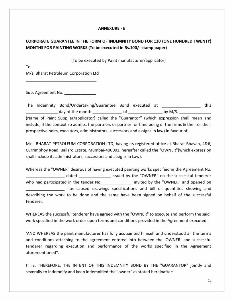
74
ANNEXURE - E
CORPORATE GUARANTEE IN THE FORM OF INDEMNITY BOND FOR 120 (ONE HUNDRED TWENTY)
MONTHS FOR PAINTING WORKS (To be executed in Rs.100/- stamp paper)
(To be executed by Paint manufacturer/applicator)
To,
M/s. Bharat Petroleum Corporation Ltd
_______________________________
Sub: Agreement No. ______________
The Indemnity Bond/Undertaking/Guarantee Bond executed at _________________ this
______________ day of the month _____________ of _______________ by M/S. ______________
(Name of Paint Supplier/applicator) called the "Guarantor” (which expression shall mean and
include, if the context so admits, the partners or partner for time being of the firms & their or their
prospective heirs, executors, administrators, successors and assigns in law) in favour of:
M/s. BHARAT PETROLEUM CORPORATION LTD, having its registered office at Bharat Bhavan, 4&6,
Currimbhoy Road, Ballard Estate, Mumbai-400001, hereafter called the "OWNER"(which expression
shall include its administrators, successors and assigns in Law).
Whereas the "OWNER" desirous of having executed painting works specified in the Agreement No.
_________________ dated ______________ issued by the “OWNER" on the successful tenderer
who had participated in the tender No______________ invited by the "OWNER" and opened on
_________________ has caused drawings specifications and bill of quantities showing and
describing the work to be done and the same have been signed on behalf of the successful
tenderer.
WHEREAS the successful tenderer have agreed with the "OWNER" to execute and perform the said
work specified in the work order upon terms and conditions provided in the Agreement executed.
‘AND WHEREAS the paint manufacturer has fully acquainted himself and understood all the terms
and conditions attaching to the agreement entered into between the ‘OWNER’ and successful
tenderer regarding execution and performance of the works specified in the Agreement
aforementioned".
IT IS, THEREFORE, THE INTENT OF THIS INDEMNITY BOND BY THE "GUARANTOR" jointly and
severally to indemnify and keep indemnified the "owner" as stated hereinafter:

75
1.0 Frame work and purpose of this contract
This contract defines what constitutes a defect in the coating system and what are the rights,
obligations and liabilities of the parties in case of defect.
1. The Guarantee
a. The "GUARANTOR" hereby confirms having carefully examined the coating system supplied
by the "OWNER" in the tender document. Considering all technical aspects & climatic
conditions prevailing at the location, the "GUARANTOR" confirm that specified coating
system are fully suitable for the desired services on mild steel vertical oil storage tanks, steel
structures and steel pipelines etc. at the location.
b. The " Paint supplier/ Applicator” hereby confirms that they will ensure thorough surface
preparation as per specified Swedish Standards so as to have desired surface profile before
application of paint system on the steel surface.
c. The "GUARANTOR" hereby agrees to provide all latest codes, SSPC guidelines for painting,
providing surface profile comparators, wet & dry film thickness measuring gadgets and
other painting inspection kits for inspection by "OWNER" conforming to latest SSPC
guidelines for painting inspection.
d. The " Paint supplier/ Applicator hereby confirms to provide Dry Film Thickness (DFT) of
paint specified for every coat .If, actual DFT of a particular coat is beyond the permissible
limits of acceptance of variation in DFT, the "GUARANTOR" undertakes to blast the painted
surface again and apply paint system so as to achieve the specified DFT for every coat.
e. The "GUARANTOR" hereby confirms that the coating system will be free from the defects
i.e. chalking, cracking, alligatoring, flaking, peeling delamination, rusting, blistering,
wrinkling, edge failure and failure around welds etc. during the Guarantee period of the
coating system. The Guarantors guarantee the performance of the coating system during
the Guarantee period.
f. "Performance" means that there will be no defective areas of the coating system during the
Guarantee period.
g. The "GUARANTOR"(Paint supplier/ Applicator) hereby agree that guarantee period of
coating system will commence on the completion of work as detailed in the Agreement No.
___________ dated _____________. This corporate guarantee shall commence on

76
completion of retention period of two years from the date of completion of work. (The
Painting Contractor shall provide Bank Guarantee for the first two years from the date of
completion). It expires 8 (Eight) Years after commencement of corporate guarantee period.
However, the "OWNER’ agrees that guarantee period shall not be extended by any repairs
or repainting made during this guarantee period.
h. "Defective Areas" mean an area or areas where spontaneous visible corrosion has broken
the paint film to a degree exceeding Rust grade No.6 (1% or more of the area painted) of
SSPC Visual Standard No.2 (Guide to Standard method of evaluating Degree of rusting on
painted steel surfaces), within the Guarantee period and or where softening of paint and or
peeling of paint is noticed. Irrespective of the paint in other respects, such as but not limited
to staining, loss of gloss on an area is not considered defective when corrosion activity is
rust grade No.6 or less during the said Guarantee period :
i. The " Paint supplier/ Applicator (GUARANTOR) hereby confirms that in case of premature
paint failure attributable to the quality of the paint, this Guarantee covers that the
Guarantor will supply paint free of cost and will repaint/rectify free of cost for those areas
(defective) where premature paint failure has been accepted and is attributable to the
quality of paint and or workmanship.
1. EXCLUSIONS/Force Majure
The "GUARANTOR" shall have no liability under this contract for the following:
a. Deterioration and damage to the painting system not caused by wear and tear but by
Welding or other heating, Mechanical action, Fire, Explosion, unusual action of the elements
or any other occurrence outside the Guarantor control, and loss or damage which is a
consequence of the aforementioned excluded causes and occurrences.
b. Coating areas on which repair or other works have been performed by the "owner" after
commencement of painting.
c. Deterioration of coating system caused by physical abuse such as on walkways, handrails,
ladders etc.
d. The " Paint supplier and Applicator” obligations are automatically waived off and void if
coating system are affected as consequences of strike, war, invasion, acts of terrorism, or
foreign enemies, hostilities, civil war, rebellion, insurrection, military or usurped power,
confiscation or Nationalization or requisition or destruction of or damage to property by or
under the order of any Govt or authority and to the extent that loss or damage is directly or
indirectly caused by such circumstances or natural catastrophe.

77
Authorized Signatory of the Paint Manufacturer/Applicator
Name of the Paint manufacturer/ Applicator : ____________________________
Address of the Paint manufacturer/ Applicator : ____________________________
____________________________
____________________________
Seal :
WITNESS
1.
2.

78
ANNEXURE – F
Procedure for Measurement of Dry Film Coating Thickness
Definitions: DFT – Dry Film Thickness
Gauge Reading – A single DFT reading at one point
Spot – A circle of 4 cm diameter
Spot Measurement - Average of acceptable three gauge readings within a spot (circle of 4 cm
diameter)
Spot Measurement Procedure: Minimum of three (3) gauge readings shall be made for each spot measurement of either the substrate or the coating. Repeated gauge readings, even at points close together, may differ due to small surface irregularities of the coating and the substrate. For each new gauge reading move the probe to a new location within 4 cm diameter circle defining the spot. Discard any unusually high or low reading that cannot be repeated consistently. Take the average of the acceptable gauge readings as the spot measurement. Required Number of Measurements for Conformance to a thickness specification Number of Measurements: Make five (5) spot measurements spaced randomly over each 10 m2 (100 ft2) area to be measured. No. of spot measurement beyond five for an area of 10 m2 can be increased as decided by BPCL. The five spot measurements shall be made for each 10 m2 (100 ft2) of area as follows :
a. For structures not exceeding 30 m2 (300 ft2) in area, each 10 sq m2 (100 ft2) area shall be measured.
b. For structures not exceeding 100 m2 (1000 ft2) in area, three 10 m2 (100 ft2) areas shall be randomly selected and measured.
c. For structures exceeding 100 m2 (1000 ft2) in area, the first 10 m2 (1000 ft2) shall be measured as
stated in (b) above and for increment thereof or each additional 100 m2 (1000 ft2) of area, one 10 m2
(1000 ft2) area shall be randomly selected and measured.
d. If the dry film thickness for any 10 m2 (100 ft2) area as mentioned in (b) & ( c) above is not in compliance with the requirements of (e) & (f) as mentioned below, then additional measurements must be made to isolate the nonconforming area.

79
Specifying Thickness : Both a maximum and a minimum DFT should be specified for the coating. If a maximum thickness value is not explicitly specified, the specified thickness shall be minimum.
e. Minimum thickness : The average of five spot measurements for each 10 m2 (100 ft2) area shall not be less than the specified minimum DFT. The average of three guage readings at any single spot measurement in any 10 m2 (100 ft2) area s hall not be less than 80% of the specified minimum DFT. If the average of five spot measurements for a given 10 m2 (100 ft2) area meets or exceeds the specified minimum DFT and any spot measurement does not met 80% of the specified minimum DFT , additional spot measurements may be made to define the non-conforming areas.
f. Maximum thickness : The average of five spot measurements for each 10 m2 (100 ft2) area shall not be more than the specified maximum DFT. No single spot measurement in any 10 m2 (100 ft2) area shall be more than 120% of the specified minimum DFT. If the average of the five spot measurements of a given 10 m2 (100 ft2) area meets or falls below the specified maximum DFT, but one or more spot measurements is more than 120% of the specified minimum DFT, additional spot measurements may be made to define the non-conforming area .

80

81
TABLE – 8

82

83
ANNEXURE – G
SPECIFICATION FOR THERMALLY SPRAYED ALUMINIUM (TSA) COATING
1.0 SCOPE:
The following sections outlines the requirement of supply, application and testing of thermally sprayed aluminum, coatings (TSAC) for corrosion protection of insulated carbon steel piping and equipments with design temperature not exceeding 5400C.
2.0 ITEMS TO BE THERMALLY SPRAYED:
Steel Structures/equipments to be protected by TSAC shall be as per standard 3C of this standard specification. Structures, components thermally sprayed shall not have any uncoated area or shall not be in mechanically connected by flanges etc. to any uncoated bare steel work. Such adjacent areas to TSA coated areas, if not coated by TSA shall have suitable paint coating system as per the standard specification.
3.0 TSAC REQUIREMENTS:
3.1 Surface Preparation:
All the parts to be sprayed shall be degreased according to SSPC-SP 1. The absence of oil and grease after degreasing shall be tested by method given elsewhere in the specification (Refer Sec.6.7). Thereafter the surface to be abrasive blasted to white metal finish as per NACE 1/SSPC-SP 5 for marine and immersion service. Using SSPC VIS 1, it is to be visually assessed that the blast cleaned surface meets requirement of SSPC-SP 5. Thereafter clear cellophane tape test as per ISO 8502-3 shall be used to confirm absence of dust on the blasted surface. Finally blasted surface shall be tested for presence of soluble salts as per method ISO 8502-9. Maximum allowable salt content shall be considered 50mg/m2. (5 micrograms/cm2). In case salt content exceeds specified limit. The contaminated surface shall be cleaned by method as per Annex C of IS 12944-4 (Water Cleaning). After cleaning the surface shall be retested for salt content after drying. Testing shall be carried out at least on each component, once per 200 m2 and a min of 3 times per shift during progress of work.
The blasting media shall be either chilled iron or angular steel grit as per SSPC-AB-3 of mesh size G-16 to G-40. Copper, Nickel slag, Garnet or Aluminum Oxide as abrasives will also be suitable having mesh size in the range of G16 to G24 (10-30 mesh), conforming to SSPC-AB-1. Mesh size shall be required as appropriate to the anchor tooth depth profile requirement and blasting equipment used. The blasted surface should be having angular profile depth not less than 65 microns with sharp angular shape but shall not exceed 85 microns. The profile depth shall be measured according to NACE standard RP 0287 (Replica Tape) or ASTM D 4417 method B (Profile depth gauge).

84
For manual blasting one profile depth measurement shall be taken every 10 - 20m2 of blasted surface.
Surface preparation shall be completed in one abrasive blasting cleaning operation wherever possible.
If rust bloom (visual appearance of rust) appears on the blast cleaned surface before thermal spraying, the affected area shall be reblasted to achieve specified degree of cleanliness after which only thermal spraying shall commence.
Air blasting pressure at nozzle shall be normally maintained at 100 psi. Air pressure and media size should be reduced and adjusted to preclude damage/distortion to thin gauge materials. Blasting time on work piece should be adjusted to only clean the surface and cut required anchor tooth with minimum loss of metal. Blast angle should be as close to perpendicular as possible but in no case greater than ± 30
0 from perpendicular to work surface. Blasting media must be free of debris, excessive fines, and contaminants such as NaCl and sulfur salts (Ref. SEC 6.0 of this Spec.). Blast cleaning shall not be performed when the surfaces to be blasted are wet or less than 5
0 C above dew point temperature or when the relative humidity in the vicinity of the work is greater than 90%.
3.1.1 Blasting Equipment:
The TSAC applicator shall use mechanical (centrifugal wheel) or pressure pot blast cleaning equipment and procedures. Suction blasting equipment shall not be used. Sec. 6.6.2 shall be used to validate clean and dry air.
3.1.2 Feed Stock:
The feed stock shall be in form of wire. The feed stock shall be 99.5% aluminum of commercial purity grade, its composition shall be in accordance with requirement of BS 1475 or ASTM B833 or ISO 209-1 type A 1 (wrought aluminum and aluminum alloys, wire). Wire shall be supplied in protective wrapping indicating batch number and other details.
3.1.3 Thickness Requirement:
The nominal thickness of finished TSAC shall be 250 microns having minimum value of 225 microns at low thickness area (valleys) and not more than 275 microns at peak areas.
The finished thickness shall be measure using SSPC-PA 2 type 2 fixed probe gauge (Magnetic Gauge).
3.1.4 Coating Bond Strength Requirement:

85
The TSAC coating shall have a minimum individual tensile-bond strength value of 1000 psi for flame sprayed and 1500 psi for arc sprayed coating with an average of 2000 psi for arc sprayed coatings. Minimum tensile bond strength should be achieved by proper anchor tooth profile of blasted surface, laying down the TSA thickness in multiple passes and carrying out TSA application under controlled environment.
3.1.5 Porosity:
All thermally sprayed metallic coatings will have porosity. For thermally sprayed aluminium coatings porosity shall not exceed 15% of total surface area for flame sprayed coating and 8% for arc spray coating.
4.0 THERMAL SPRAY APPLICATION PROCEDURE:
Items in the atmospheric zone to be coated by TSA shall be applied by either Flame spray or Arc spray method only. For coating under insulation, application shall be by arc wire method.
4.1 Equipment Set Up:
4.1.1. Thermal spray equipment shall be set up calibrated, operated (1) according to manufacturer instructions/technical manuals and also TSAC applicators refinement thereto and (2) as validated by Procedure Qualification (See 7.0 of this application).
4.1.2 Spray Parameters:
Spray parameters (see table - 9 below) and thickness of each crossing pass shall be set and shall be validated with bend test (See 6.5 of this Spec.).
4.1.3 Spray Parameters:
Spray Parameters Method of Application
Arc voltage Arc wire Spray Flame Wire Spray
27 V -
Air pressure 80 psi 80 psi
Steel surface cleanliness NACE-1 white metal NACE-1 white metal/or Near White metal
Steel surface profile 75 microns (minimum) 75 microns (min.)
Arc current 250 - 280A -
Coating thickness 225 microns (nominal) 225 microns (nominal)
Coating adhesion > 1500 psi (Total coating), see
3.1.4
>1000 psi
Coating porosity Less than 8% Less than 15%
Spray distance (spray Gun work place)
6-8” 5-7”
Spray Pass width 40 mm 20 mm
86
The above parameters to be validated with a bend test by the contractor before start of work (for details of bend test see Sec.6.5 of this Spec.). 4.2 Post Blasting Substrate Condition and Thermal Spraying Period.
4.2.1 The steel surface temperature shall be at least 50C above dew point of ambient air
temperature.
Steel substrate surface temperature shall be recorded by with a contract pyrometer. Thermal spraying should commence within 15 minutes from the time of completion of blasting.
4.2.2 Holding Period:
Time between the completion of final anchor tooth blasting and completion of thermal spraying of blasted surface should be no more than four hours. If within this period rust bloom appears Sec.4.4.1 of this specification will apply.
4.3 Pre-Heating:
For flame spraying, the initial starting area of 1 - 2 square feet to be preheated to approx. 1200 C to prevent condensation of moisture in the flame on the substrate. For arc spraying the preheating is not required.
4.4 Thermal Spraying:
Spraying should commence only after validation of equipment set up by procedure qualification test and spray parameter validation tests described in Sec 7.0 and 6.5 respectively. Thermal spraying must commence within 15 minutes from the time of completion of blast cleaning.
The specified coating thickness shall be applied in several crossing passes. The coating bond strength is greater when the spray passes are kept thin. Laying down an excessively thick spray pass increases the internal stresses in TSAC and decreases the bond strength of total TSAC. The suitable thickness for crossing passes shall be determined by procedure qualification test described in Sec 7.0 of this specification.
For manual spraying, spraying to be done in perpendicular crossing passes to minimize thin spots in coating. Approx. 75 - 100 microns of TSAC shall be laid down in each pass.
The surface geometry of the item or area to be sprayed should be inspected before application. The spraying pass and sequence shall be planned according to following.
- Maintain Gun as close to perpendicular as possible and within ± 30
0 from perpendicular to the substrate.

87
- Maintain nominal standoff distance and spray pass width as given below:
Spray Method Standoff (Inches)
Spray pass width (Inches)
Arc Wire 6 - 8 1 ½ (40 mm)
Flame wire 5 - 7 ¾ (20 mm)
4.4.1 Rust Bloom (Visual appearance of rust or Discoloration):
If Rust bloom appears on the blasted surface before thermal spraying, the affected area shall be reblasted to achieve the specified level of cleanliness.
If Rust bloom in form of discoloration, or any blastering or a degraded coating appears at any time during application of TSAC, then spraying shall be stopped and acceptable sprayed area shall be marked off. The unsatisfactory areas shall be repaired to the required degree of surface cleanliness and profile.
Blast the edges of the TSAC to provide 2 – 3” feathered area overlap of the new work into existing TSAC.
Then apply TSAC to the newly prepared surfaces and overlap the existing TSAC to the extent of feathered edge so that overlap is a consistent thickness.
4.4.2 Masking:
Masking all those parts and surfaces which are not required to be thermally sprayed as instructed by purchaser should be inspected by applicator to ensure that they are properly marked and covered by purchaser.
Complex geometries (flanges, valve manifolds, intersections) shall be masked by applicator to minimize overspray i.e. TSAC applied outside spray parameters (primarily gun to substrate distance and spray angle).
4.4.3 TSAC Finish:
The deposited TSAC shall be uniform without blisters, cracks, loose particles, or exposed steel as examined with 10 X magnification.
5.0 SEALER:
Sealant shall be applied after satisfactory application of TSAC and completion of all testing and measurements of the finished TSAC as per Sec 6.0 of this specification.

88
For shop work Sealer shall be applied immediately after thermal spraying and for field work sealer shall be applied within 8 hours. The sealcoat shall be thin enough to penetrate into the body of TSAC.
The sealant shall be Silicone Alkyd Aluminum paint having DFT not more than 35 – 40 micron. Typically seal coast shall be applied at a spreading rate resulting in theoretical 38 microns DFT. The seal coat shall be applied in accordance with SSPC-PA 1 and the paint manufacturer instruction for sealing.
6.0 TESTING AND MEASUREMENT SCHEDULE:
6.1 Surface Finish:
That the blasted cleaned surface meets the required criteria (NACE 1/SSPC-SP 5) shall be visually inspected using SSPC-VIS 1. The clear cellophane-tape test as per ISO 8502-3 shall be used to confirm absence of dust or foreign debris on the cleaned surface. Checks shall be done on each component at least once per 200 m2 of blasted surface and minimum of 3 checks per shift.
6.2 Blast Profile Measurement: (In-Process testing during actual production before application
of TSA coating)
The angular profile depth measurement shall be done by profile tape as per method NACE Standard RP 0287 or ASTM D 4417 method B (Profile depth gauge micrometer). Spot measurement shall be carried out every 15 m2 of blasted surface. At each spot three measurements shall be taken over an area of 10 cm2 and average of measurements to be recorded and reported. If profile is <65 microns blasting shall continue till greater than 65 microns depth profile is achieved.
6.3 TSAC Thickness (In-Process Testing for finished coating during regular production)
6.3.1 TSAC finished thickness shall be measured using SSPC-PA 2 type 2 fixed probe gauge. 6.3.2 For flat surfaces, measurements shall be taken along a straight measurement line,
one measurement line for every 15 m2 of applied TSAC shall be selected along which 5 measurements to be taken at 25 mm internal and average to be reported.
6.3.3 For curved surface or complex geometry, 5 measurements shall be taken at a spot
measuring 10 cm2 in area. One spot to be taken for every 15 m2 of applied TSAC area.
6.3.4 The TSAC thickness in surface changes or contour changes, welds and attachments
shall be also measured and reported. 6.3.5 If TSAC is less than specified minimum thickness, apply additional TSAC until
specified thickness range is achieved.

89
6.3.6 All locations and values of TSAC thickness measurements shall be recorded in Job
Record (JR). 6.4 Tensile Bond Testing (In-Process testing for finished coating during regular production)
- Tensile Bond strength of the TSAC finish coat shall be determined according to ASTM D 4541 using a self-aligning adhesion tester.
- One measurement shall be made every 50 m2. If tensile bond at any individual spot
is less than 1000 psi for flame sprayed coating and 1500 psi for arc sprayed coating the degraded TSAC shall completely removed and reapplied.
- The tensile bond portable test instrument to be calibrated according to ASTM C 633.
6.5 Bend Tests:
Bend test shall be carried out at beginning of each work shift. Bend tests shall also be conducted on sample coupons before start of thermal spraying work to qualify the following as mentioned earlier in this specification.
- To qualify spray parameters and thickness of each crossing pass.
6.5.1 Test Procedure:
a) Five corrosion control steel coupons each of dimension 50 mm x 150 mm x
1.3 mm thk. to be prepared. b) Surface shall be prepared by dry abrasive blast cleaning as per this
specification. c) TSAC shall be applied as per specified thickness range. TSAC should be
sprayed in crossing passes laying down approx. 75 – 100 microns in each pass.
d) TSAC applied coupons shall be bent 1800 around a 13 mm diameter mandrel. e) Bend test shall be considered passed if on bend radius there is
- No cracking or spalling or lifting by a knife blade from the substrate - Only minor cracking that cannot be lifted from substrate with a knife
blade.
f) Bend test fails if coating cracks with lifting from substrate.

90
6.6 Tests for blasting media, blasting air
6.6.1 Blasting Media (For every fresh batch of media and one random test during blasting)
Blasting Media shall be visually inspected for absence of contamination and debris using 10 X magnification.
a) Inspection for the absence of oil contamination shall be conducted using
following procedure:
- Fill a small clean 200 ml bottle half full of abrasive. - Fill the bottle with potable water, cap and shake the bottle. - Inspect water for oil film/slick. If present, the blasting media is not to be
used.
b) Soluble salt contamination if suspected shall be verified by method ASTM D 4940. If present, media to be replaced.
c) Clean blasting equipment, especially pot and hoses, and then replace blasting
media and retest.
6.6.2 Test for Blasting Air (Once Daily before start of blasting and once at random during blasting).
The air for blasting shall be free from moisture and oil. The compressor air shall be checked for oil and water contamination per ASTM D 4285.
6.7 Test for presence of oil/grease and contamination
The steel substrate after degreasing as per SSPC-SP 1 shall be tested as per following procedure to validate absence of oil and grease contamination.
a) Visual inspection – Continue degreasing until all visible signs of contamination are
removed. b) Conduct a solvent evaporation test by applying several drops or a small splash or
residue-free dichloromethane on the suspect area especially pitting, crevice corrosion areas or depressed areas. An evaporation ring formation is indicative of oil and grease contamination.
Continue degreasing and inspection till test is passed.

91
7.0 TSAC APPLICATOR QUALIFICATION:
Following tests to be carried out as part of procedure qualification test for the applicator.
- Thickness measurement - Coating bond strength - Porosity test - Bend strength
TSAC applicator’s surface finishing and application process and equipment set up, calibration and operation shall be qualified by application of TSA on a reference sample which shall be used as a comparator to evaluate the suitability of application process. Only that applicator will be permitted to carry out the work when test specimens coated by the applicator meets the desired requirements as cited below.
The sample shall be made of a steel plate measuring approx. 18” x 18” x ¼” thick. If the actual work is less than ¼” thick then the sample to be made from material of representative thickness. The surface preparation, TSAC application shall be made with actual field equipments and process/spray parameters and procedures as per the specification. The depth profile of blasted surface, TSAC coating thickness for each cross pass and total thickness range shall be as per specification. The surface preparation and thermal spraying shall be carried out in representative environmental conditions spraying with makeshift enclosure.
7.1 After application of coating, thickness and tensile bond measurements shall be made in
following manner.
- Divide the sample piece into four quadrants. - Measure thickness along the diagonal line of each quadrant. - For each quadrant five in-line thickness measurements at 1” interval shall be done using
SSPC-PA 2 type 2 fixed probe gauge. Thus a total of four “five in line” thickness measurements to be done for the whole sample.
- One tensile bond measurement using ASTM D 4541 type III or IV portable self aligning test instrument to be done at centre of each quadrant. Total of 4 measurements for the sample.
- One porosity evaluation test by Metallographic examination shall be conducted to demonstrate the achievement of porosity within the limits specified. Sample shall be prepared for Metallographic examination as per ASTM E-3.
92
- The procedure shall be considered qualified if thickness and tensile-bond strength and porosity values meet the specification requirement.
7.2 Bend Test: Bend test shall be carried out as detailed at Sec.6.5 of this specification.
Applicators thermal spray equipment set-up, operation and procedure of application including in-process QC checkpoints adopted during procedure qualification as described above should be always subsequently followed during entire duration of work.
8.0 DOCUMENTATION:
The following information shall be provided by TSAC applicator before award of work.
- TSAC application process consisting of equipment capabilities and their technical parameters, feed stock material and source of procurement.
- Detailed application procedure and in-process quality control check points for (a) surface
preparation (b) thermal spraying (c) seal coats.
- Type and specification of instruments to be deployed for measurement of blast profile depth, TSAC thickness and tensile bond.
- Paint manufacturer data sheet for the selected sealing coat to be applied.
9.0 RECORDS:
- The TSAC applicator shall maintain job record to record production and QC information. All the results of the tests and quality control checks shall be entered in the record for each component/part thermally sprayed. All the result of tests (thickness, tensile bond, bond tests) and other validation tests (e.g. procedure qualification test, test for surface cleanliness after abrasive blasting, test for cleanliness of abrasives and air) shall also be recorded and duly signed by owner.
- All the information mentioned in Sec 8.0 above should also form part of the job record.
- Any modification affected after procedure qualification in the procedure, QC, spray parameter, equipment spec to the original information (submitted before award of the work) must also form part of Job record.
10.0 WARRANTY:
The TSAC applicator shall warrant the quality of material used by providing the purchaser with a certificate of materials used to include

93
- Spray feed stock: Alloy type/designation, Lot Number, wire diameter, chemical analysis, name of supplier, manufacturer.
- Sealant: Name of manufacturer, application data sheet.
11.0 SAFETY:
The TSAC applicator shall follow all safety procedures required by the purchaser/owner. Owner shall also give compliance requirement to be followed by applicator. The applicator shall follow all appropriate regulatory requirements.
12.0 CODES AND STANDARDS:
This specification shall apply in case of conflict between specification and following applicable standards:
AWS C.2.17 Recommended Practice for Electric arc Spray
ASTM C 633 Test Method for Adhesive/Cohesive Strength of Flame Sprayed Coatings
ASTM D 4285 Method for indicating Oil or Water in Compressed Air
ASTM D 4417 Test Method for Field Measurement of Surface Profile of Blasted Steel
BS 2569 Specification for Sprayed Metal Coating
NACE Standard RP 0287 Field Measurement of Surface Profile of Abrasive Blast Cleaned Steel Surfaces using a Replica Tape
ASTM D 4541 Test method for Pull-Off Strength of Coating Using Portable Adhesion Testers
ANSI/AWS C2.18 Guide for the Protection of Steel with Thermal Spray Coatings of Aluminum, Zinc and their Alloys and Composites
NACE No.12/AWS C2.23M/SSPC-CS 23.00
Specification for the application of thermal spray coatings (Metalizing) of aluminum, zinc, and their alloys and composites for the corrosion protection of steel
SSPC Publication The inspection of coating and linings: A Handbook of Basic practice for Inspectors, Owners and Specifiers
SSPC-AB 1 Mineral and Slag Abrasives
SSPC-AB 3 Ferrous Metallic Abrasives
SSPC-PA 1 Shop, Field and Maintenance Painting of Steel
SSPC-PA 2 Measurement of Dry Coating Thickness with Magnetic Gages
NACE No.1/SSPC-SP 5 White Metal Blast Cleaning
NACE No.2/SSPC-SP 10 Near – White Metal Blast Cleaning
SSPC-VIS 1 Guide and Reference Photographs for Steel Surfaces Prepared by Dry Abrasive Blast Cleaning
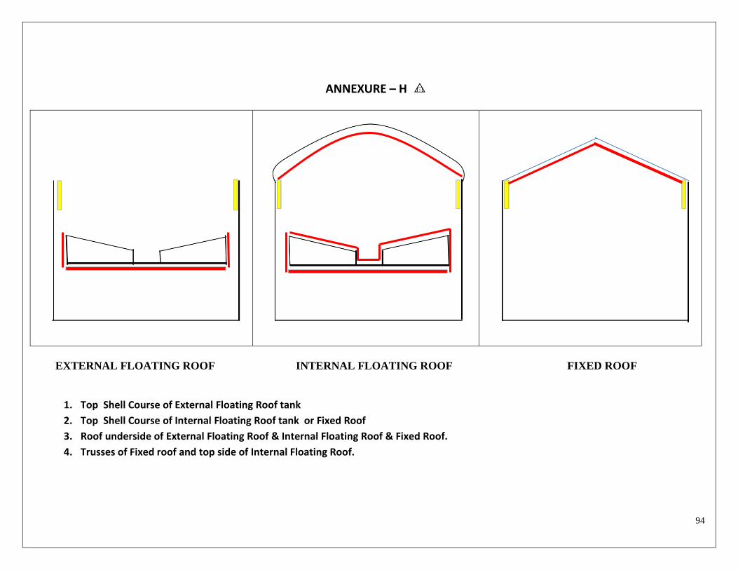
94
ANNEXURE – H
EXTERNAL FLOATING ROOF INTERNAL FLOATING ROOF FIXED ROOF
1. Top Shell Course of External Floating Roof tank
2. Top Shell Course of Internal Floating Roof tank or Fixed Roof
3. Roof underside of External Floating Roof & Internal Floating Roof & Fixed Roof.
4. Trusses of Fixed roof and top side of Internal Floating Roof.
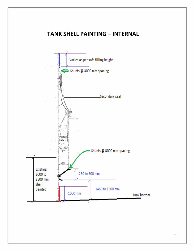
95
TANK SHELL PAINTING – INTERNAL

96
ANNEXURE – I
BRAND NAMES OF PAINTS: Note: These brand names of paints are indicative; continuous change in product name shall be considered during execution. Only five vendors’ brand names are mentioned herewith as indicative, however other approved vendors equivalent brands shall also be treated as accepted. In case of conflict between generic name and product name, Generic name of the paint for the specified services shall be considered final.
Table – A
BPCL SPECIFICATIONS M/S ASIAN M/S SIGMA
SR. NO. SYSTEM PRIMER SPECIFIED
VOL. SOLIDS
BRAND NAME Vol. Solids
% BRAND NAME
Vol. Solids %
1 P1 Inorganic Zinc ethyl silicate primer (Minimum 85% Zinc dust by weight in the dried film)
60 2 % Apcosil 605(85%) 65 Sigmazinc 170 65
2 P2 Epoxy red oxide zinc phosphate primer
50 2 % Apcodur EHB ZP Primer 58 Sigmacover 246 64
3 P4 Self priming surface tolerant epoxy mastic paint
80 ±2 % Rust-O-Cap 80 Sigmacover 620 80
4 P5 Amine Adduct Cured Epoxy Holding Primer
60 2 % Apcodur CP 682 58 Not Available
5 P6 Two Component Polyamide cured Epoxy Primer
57%±2 % Apcodur EHB ZP Primer 58 Sigmacover 280 57
6 P7 Epoxy red oxide zinc phosphate PRIMER SUITABLE FOR GI SURFACE
50 3 % Apcodur CP 681 58 Sigmacover 280 57
FINISH PAINTS
7 F1 High build two pack ployamide cured epoxy
60 2% Asian HB Epoxy Coating 65 Sigmacover 410 80
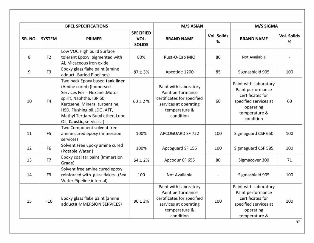
97
BPCL SPECIFICATIONS M/S ASIAN M/S SIGMA
SR. NO. SYSTEM PRIMER SPECIFIED
VOL. SOLIDS
BRAND NAME Vol. Solids
% BRAND NAME
Vol. Solids %
8 F2 Low VOC High build Surface tolerant Epoxy pigmented with Al, Micaceous iron oxide
80% Rust-O-Cap MIO 80 Not Available -
9 F3 Epoxy glass flake paint (amine adduct -Buried Pipelines)
87 3% Apcotide 1200 85 Sigmashield 905 100
10 F4
Two pack Epoxy based tank liner (Amine cured) (Immersed Services For - Hexane ,Motor spirit, Naphtha, IBP 60, Kerosene, Mineral turpentine, HSD, Flushing oil,LDO, ATF, Methyl Tertiary Butyl ether, Lube Oil, Caustic, services. )
60 2 %
Paint with Laboratory Paint performance
certificates for specified services at operating
temperature & condition
60
Paint with Laboratory Paint performance
certificates for specified services at
operating temperature &
condition
60
11 F5 Two Component solvent free amine cured epoxy (Immersion services)
100% APCOGUARD SF 722 100 Sigmaguard CSF 650 100
12 F6 Solvent Free Epoxy amine cured (Potable Water )
100% Apcoguard SF 155 100 Sigmaguard CSF 585 100
13 F7 Epoxy coal tar paint (Immersion Grade)
64 2% Apcodur CF 655 80 Sigmacover 300 71
14 F9 Solvent free amine cured epoxy reinforced with glass flakes. (Sea Water Pipeline internal)
100 Not Available - Sigmashield 905 100
15 F10 Epoxy glass flake paint (amine adduct)(IMMERSION SERVICES)
90 ± 3%
Paint with Laboratory Paint performance
certificates for specified services at operating
temperature & condition
100
Paint with Laboratory Paint performance
certificates for specified services at
operating temperature &
100
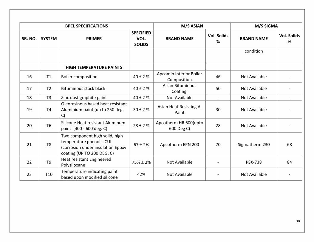
98
BPCL SPECIFICATIONS M/S ASIAN M/S SIGMA
SR. NO. SYSTEM PRIMER SPECIFIED
VOL. SOLIDS
BRAND NAME Vol. Solids
% BRAND NAME
Vol. Solids %
condition
HIGH TEMPERATURE PAINTS
16 T1 Boiler composition 40 ± 2 % Apcomin Interior Boiler
Composition 46 Not Available -
17 T2 Bituminous stack black 40 ± 2 % Asian Bituminous
Coating. 50 Not Available -
18 T3 Zinc dust graphite paint 40 ± 2 % Not Available - Not Available -
19 T4 Oleoresinous based heat resistant Aluminium paint (up to 250 deg. C)
30 ± 2 % Asian Heat Resisting Al
Paint 30 Not Available -
20 T6 Silicone Heat resistant Aluminum paint (400 - 600 deg. C)
28 ± 2 % Apcotherm HR 600(upto
600 Deg C) 28 Not Available -
21 T8
Two component high solid, high temperature phenolic CUI (corrosion under insulation Epoxy coating (UP TO 200 DEG. C)
67 2% Apcotherm EPN 200 70 Sigmatherm 230 68
22 T9 Heat resistant Engineered Polysiloxane
75% 2% Not Available - PSX-738 84
23 T10 Temperature indicating paint based upon modified silicone
42% Not Available - Not Available -
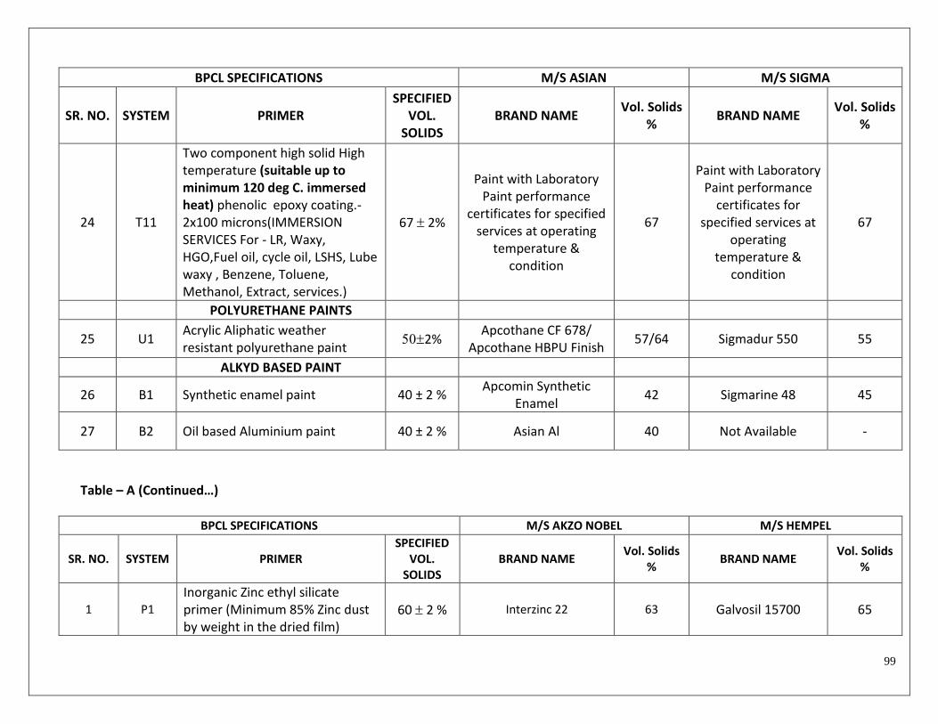
99
BPCL SPECIFICATIONS M/S ASIAN M/S SIGMA
SR. NO. SYSTEM PRIMER SPECIFIED
VOL. SOLIDS
BRAND NAME Vol. Solids
% BRAND NAME
Vol. Solids %
24 T11
Two component high solid High temperature (suitable up to minimum 120 deg C. immersed heat) phenolic epoxy coating.-2x100 microns(IMMERSION SERVICES For - LR, Waxy, HGO,Fuel oil, cycle oil, LSHS, Lube waxy , Benzene, Toluene, Methanol, Extract, services.)
67 2%
Paint with Laboratory Paint performance
certificates for specified services at operating
temperature & condition
67
Paint with Laboratory Paint performance
certificates for specified services at
operating temperature &
condition
67
POLYURETHANE PAINTS
25 U1 Acrylic Aliphatic weather resistant polyurethane paint
2% Apcothane CF 678/
Apcothane HBPU Finish 57/64 Sigmadur 550 55
ALKYD BASED PAINT
26 B1 Synthetic enamel paint 40 ± 2 % Apcomin Synthetic
Enamel 42 Sigmarine 48 45
27 B2 Oil based Aluminium paint 40 ± 2 % Asian Al 40 Not Available -
Table – A (Continued…)
BPCL SPECIFICATIONS M/S AKZO NOBEL M/S HEMPEL
SR. NO. SYSTEM PRIMER SPECIFIED
VOL. SOLIDS
BRAND NAME Vol. Solids
% BRAND NAME
Vol. Solids %
1 P1
Inorganic Zinc ethyl silicate primer (Minimum 85% Zinc dust by weight in the dried film)
60 2 % Interzinc 22 63 Galvosil 15700 65

100
BPCL SPECIFICATIONS M/S AKZO NOBEL M/S HEMPEL
SR. NO. SYSTEM PRIMER SPECIFIED
VOL. SOLIDS
BRAND NAME Vol. Solids
% BRAND NAME
Vol. Solids %
2 P2 Epoxy red oxide zinc phosphate primer
50 2 % Intergard 251 63 Hempadur 1530C 51
3 P4 Self priming surface tolerant epoxy mastic paint
80 ±2 % Inteseal 547 80 Hempadur Mastic
47550 81
4 P5 Amine Adduct Cured Epoxy Holding Primer
60 2 % Interline 1012 60 Hempadur 15500 68
5 P6 Two Component Polyamide cured Epoxy Primer
57%±2 % Intergard 251 63 Hempadur 15553 55
6 P7
Epoxy red oxide zinc phosphate PRIMER SUITABLE FOR GI SURFACE
50 3 % Intergard 269 47 Hempadur 15553 55
FINISH PAINTS
7 F1 High build two pack ployamide cured epoxy
60 2% Intergard 966 62 Hempadur Mastic
47550 81
8 F2
Low VOC High build Surface tolerant Epoxy pigmented with Al, Micaceous iron oxide
80% Interplus 256 80 Hempadur Mastic
4588 (mixed) 80
9 F3 Epoxy glass flake paint (amine adduct -Buried Pipelines)
87 3% Interzone 505 90 Multi-Strength 35870
GF 87
10 F4
Two pack Epoxy based tank liner (Amine cured) (Immersed Services For - Hexane ,Motor spirit, Naphtha, IBP 60, Kerosene, Mineral turpentine, HSD, Flushing oil,LDO, ATF, Methyl Tertiary Butyl ether, Lube Oil, Caustic, services. )
60 2 %
Paint with Laboratory Paint performance
certificates for specified services at operating
temperature & condition
60
Paint with Laboratory Paint performance
certificates for specified services at
operating temperature &
condition
60

101
BPCL SPECIFICATIONS M/S AKZO NOBEL M/S HEMPEL
SR. NO. SYSTEM PRIMER SPECIFIED
VOL. SOLIDS
BRAND NAME Vol. Solids
% BRAND NAME
Vol. Solids %
11 F5
Two Component solvent free amine cured epoxy (Immersion services)
100% Interline 925P 100 Multi-Strength
35530/1 100
12 F6 Solvent Free Epoxy amine cured (Potable Water )
100% Interline 925 100 Multi-Strength
35530/1 100
13 F7 Epoxy coal tar paint (Immersion Grade)
64 2% Not Available - Hempadur Coaltar
15130 70
14 F9
Solvent free amine cured epoxy reinforced with glass flakes. (Sea Water Pipeline internal)
100 Interline 925 GF 100 Not Available -
15 F10 Epoxy glass flake paint (amine adduct)(IMMERSION SERVICES)
90 ± 3%
Paint with Laboratory Paint performance
certificates for specified services at operating
temperature & condition
90
Paint with Laboratory Paint performance
certificates for specified services at
operating temperature &
condition
90
HIGH TEMPERATURE PAINTS
16 T1 Boiler composition 40 ± 2 % Not Available - Not Available -
17 T2 Bituminous stack black 40 ± 2 % Intertuf16 53 Hempinol 10220 50
18 T3 Zinc dust graphite paint 40 ± 2 % Not Available - Not Available -
19 T4
Oleoresinous based heat resistant Aluminium paint (up to 250 deg. C)
30 ± 2 % Intertherm 919 25 2 % Hempel Silicon Acrylic 56940
54
20 T6 Silicone Heat resistant Aluminum paint (400 - 600 deg. C)
28 ± 2 % Not Available - Hempel Silicon
Aluminium 56914 43

102
BPCL SPECIFICATIONS M/S AKZO NOBEL M/S HEMPEL
SR. NO. SYSTEM PRIMER SPECIFIED
VOL. SOLIDS
BRAND NAME Vol. Solids
% BRAND NAME
Vol. Solids %
21 T8
Two component high solid, high temperature phenolic CUI (corrosion under insulation Epoxy coating (UP TO 200 DEG. C)
67 2% Intertherm 228 67 Hempadur 85671 68
22 T9 Heat resistant Engineered Polysiloxane
75% 2% Not Available Not Available -
23 T10 Temperature indicating paint based upon modified silicone
42% Intertherm 715 42 Hempel Thermo-
Colour 56980 57
24 T11
Two component high solid High temperature (suitable up to minimum 120 deg C. immersed heat) phenolic epoxy coating.-2x100 microns(IMMERSION SERVICES For - LR, Waxy, HGO,Fuel oil, cycle oil, LSHS, Lube waxy , Benzene, Toluene, Methanol, Extract, services.)
67 2%
Paint with Laboratory Paint performance
certificates for specified services at operating
temperature & condition
67
Paint with Laboratory Paint performance
certificates for specified services at
operating temperature &
condition
67
POLYURETHANE PAINTS
25 U1 Acrylic Aliphatic weather resistant polyurethane paint
2% Interthane 138 50 Hempathane 55190 63
ALKYD BASED PAINT
26 B1 Synthetic enamel paint 40 ± 2 % Interlac 826 64 Hempalin 52140 46
27 B2 Oil based Aluminium paint 40 ± 2 % Intertherm Al 40 Hempel Al 40

103
Table – A (Continued…)
BPCL SPECIFICATIONS M/S JOTUN
SR. NO. SYSTEM PRIMER SPECIFIED
VOL. SOLIDS
BRAND NAME Vol. Solids
1 P1 Inorganic Zinc ethyl silicate primer (Minimum 85% Zinc dust by weight in the dried film)
60 2 % Resist 86 67%
2 P2 Epoxy red oxide zinc phosphate primer
50 2 % Penguard HSP ZP 73%
3 P4 Self priming surface tolerant epoxy mastic paint
80 ±2 % Jotamastic 80 80%
4 P5 Amine Adduct Cured Epoxy Holding Primer
60 2 % Tankguard Storage 63%
5 P6 Two Component Polyamide cured Epoxy Primer
60%±2 % Not Available -
6 P7 Epoxy red oxide zinc phosphate PRIMER SUITABLE FOR GI SURFACE
50 3 % Penguard Primer 51%
FINISH PAINTS
7 F1 High build two pack ployamide cured epoxy
60 2% Penguard Midcoat 82%
8 F2 Low VOC High build Surface tolerant Epoxy pigmented with Al, Micaceous iron oxide
80% Not Available -
9 F3 Epoxy glass flake paint (amine adduct -Buried Pipelines)
87 3% Marathon XHB 96%

104
BPCL SPECIFICATIONS M/S JOTUN
SR. NO. SYSTEM PRIMER SPECIFIED
VOL. SOLIDS
BRAND NAME Vol. Solids
10 F4
Two pack Epoxy based tank liner (Amine cured) (Immersed Services For - Hexane ,Motor spirit, Naphtha, IBP 60, Kerosene, Mineral turpentine, HSD, Flushing oil,LDO, ATF, Methyl Tertiary Butyl ether, Lube Oil, Caustic, services. )
60 2 %
Paint with Laboratory Paint performance
certificates for specified services at
operating temperature &
condition
60
11 F5 Two Component solvent free amine cured epoxy (Immersed services )
100% Tankguard SF 100%
12 F6 Solvent Free Epoxy amine cured (Potable Water )
100% Tankguard DW 100%
13 F7 Epoxy coal tar paint (Immersion Grade)
64 2% Not Available -
14 F9 Solvent free amine cured epoxy reinforced with glass flakes. (Sea Water Pipeline internal)
100 Not Available -
15 F10 Epoxy glass flake paint (amine adduct)(IMMERSION SERVICES)
90 ± 3%
Paint with Laboratory Paint performance
certificates for specified services at
operating temperature &
condition
96%
HIGH TEMPERATURE PAINTS
16 T1 Boiler composition 40 ± 2 % Not Available -
17 T2 Bituminous stack black 40 ± 2 % Not Available -

105
BPCL SPECIFICATIONS M/S JOTUN
SR. NO. SYSTEM PRIMER SPECIFIED
VOL. SOLIDS
BRAND NAME Vol. Solids
18 T3 Zinc dust graphite paint 40 ± 2 % Not Available -
19 T4 Oleoresinous based heat resistant Aluminium paint (up to 250 deg. C)
30 ± 2 % Aluminum Paint HR 45%
20 T6 Silicone Heat resistant Aluminum paint (400 - 600 deg. C)
28 ± 2 % Solvalitt Alu. 40%
21 T8
Two component high solid, high temperature phenolic CUI (corrosion under insulation Epoxy coating (UP TO 200 DEG. C)
67 2% Epoxy HR 63%
22 T9 Heat resistant Engineered Polysiloxane
75% 2% Not Available -
23 T10 Temperature indicating paint based upon modified silicone
42% Not Available -
24 T11
Two component high solid High temperature (suitable up to minimum 120 deg C. immersed heat) phenolic epoxy coating.-2x100 microns(IMMERSION SERVICES For - LR, Waxy, HGO,Fuel oil, cycle oil, LSHS, Lube waxy , Benzene, Toluene, Methanol, Extract, services.)
67 2% Not Available -
POLYURETHANE PAINTS
25 U1 Acrylic Aliphatic weather resistant polyurethane paint
2% Hardtop XP 63%
ALKYD BASED PAINT
26 B1 Synthetic enamel paint 40 ± 2 % Not Available -

106
BPCL SPECIFICATIONS M/S JOTUN
SR. NO. SYSTEM PRIMER SPECIFIED
VOL. SOLIDS
BRAND NAME Vol. Solids
27 B2 Oil based Aluminium paint 40 ± 2 % Not Available -