contents 1 introduction 2 vlt functional...
TRANSCRIPT

Contents
1 Introduction 3
Safety 3
Introduction 4
About this Manual 4
Assumptions 4
HP/kW conversion 5
2 VLT Functional Features 7
Drive Operation (03-14) 7
Motor and Drive Thermal Protection (15, 16, 18) 7
Set-up 1-4 and Day/Night operation (17, 29) 7
Current Monitoring and Limits (19) 7
Direction of Rotation (22) 7
Start/Stop (23) 7
Freeze Mode (25, 26) 8
Coast (27, 28) 8
Motor Ramp-up and Ramp-down Rate (31, 32) 8
Hand/Auto Modes (34) 8
CMD RUN STOP (35) 8
Bus Functions (36, 37) 8
Jog Frequency and Command (38, 39) 8
Relay Out 1, 2 (40, 41, 43, 44) 8
PID Control Functions (61-65) 8
Sleep Mode (59) 9
Terminals 53, 54, (87-88) 9
Warnings and Alarms (90-94) 9
Error Status (99) 9
3 VLT Network Strategies 11
Strategy one 11
Strategy two 11
Strategy three 12
Strategy four 12
4 VLT Special Functions 15
Special functions 15
Analog input monitoring 15
Drive relay control 15
5 Network Connection 17
VLT® HVAC Drive FLN Operating Instructions Contents
MG.11.Z2.02 - VLT is a registered Danfoss trademark 1
6 Parameters 19
Parameter settings 19
7 Start-up and Troubleshooting 21
Start-up 21
Start-up of FLN control 21
Troubleshooting 21
Faults, warnings and alarms 21
Alarms and warnings 21
Index 30
Contents VLT® HVAC Drive FLN Operating Instructions
2 MG.11.Z2.02 - VLT is a registered Danfoss trademark

1 Introduction
1.1 Safety and Caution
1.1.1 Safety
Rotating shafts and electrical equipment can be hazardous. Therefore, it is strongly recommended that all electrical work conform to
National Electrical Code (NEC) and all local regulations. Installation, start-up and maintenance should be performed only by qualified
personnel.
Factory recommended procedures, included in this manual, should be followed. Always disconnect electrical power before working on the unit. Although
shaft couplings or belt drives are generally not furnished by the manufacturer, rotating shafts, couplings and belts must be protected with securely
mounted metal guards that are of sufficient thickness to provide protection against flying particles such as keys, bolts and coupling parts. Even when the
motor is stopped, it should be considered “alive” as long as its controller is energized. Automatic circuits may start the motor at any time. Keep hands
away from the output shaft until the motor has completely stopped and power is disconnected from the controller.
Motor control equipment and electronic controls are connected to hazardous line voltages. When servicing drives and electronic controls, there will be
exposed components at or above line potential. Extreme care should be taken to protect against shock. Stand on an insulating pad and make it a habit
to use only one hand when checking components. Always work with another person in case of an emergency. Disconnect power whenever possible to
check controls or to perform maintenance. Be sure equipment is properly grounded. Wear safety glasses whenever working on electric control or rotating
equipment.
Safety Guidelines
1. The drive must be disconnected from the AC line before any service work is done.
2. The “Stop/Off” key on the LCP of the drive does not disconnect the equipment from the AC line and is not to be used as a safety switch.
3. Correct protective grounding of the equipment must be established. The user must be protected against supply voltage and the motor must be
protected against overload in accordance with applicable national and local regulations.
4. Ground currents are higher than 3 mA.
Warning against Unintended Start
1. While the drive is connected to the AC line, the motor can be brought to a stop by means of external switch closures, serial bus commands or
references. If personal safety considerations make it necessary to ensure that no unintended start occurs, these stops are not sufficient.
2. During programming of parameters, the motor may start. Be certain that no one is in the area of the motor or driven equipment when changing
parameters.
3. A motor that has been stopped may start unexpectedly if faults occur in the electronics of the drive, or if an overload, a fault in the supply AC
line or a fault in the motor connection or other fault clears.
4. If the “Local/Hand” key is activated, the motor can only be brought to a stop by means of the “Stop/Off” key or an external safety interlock
NB!
It is responsibility of user or person installing drive to provide proper grounding and branch circuit protection for incoming power and
motor overload according to National Electrical Code (NEC) and local codes.
The Electronic Thermal Relay (ETR) in UL listed VLTs provides Class 20 motor overload protection in accordance with NEC in single motor applications,
when par. 1-90 Motor Thermal Protection is set for ETR TRIP 1, ETR TRIP 2, ETR TRIP 3, or ETR TRIP 4, and par. 1-24 Motor Current is set for rated
motor (nameplate) current.
The frequency converter DC link capacitors remain charged after power has been disconnected. To avoid an electrical shock hazard,
disconnect the frequency converter from the mains before carrying out maintenance. Wait at least as follows before doing service on
the frequency converter:
VLT® HVAC Drive FLN Operating Instructions 1 Introduction
MG.11.Z2.02 - VLT is a registered Danfoss trademark 3
1
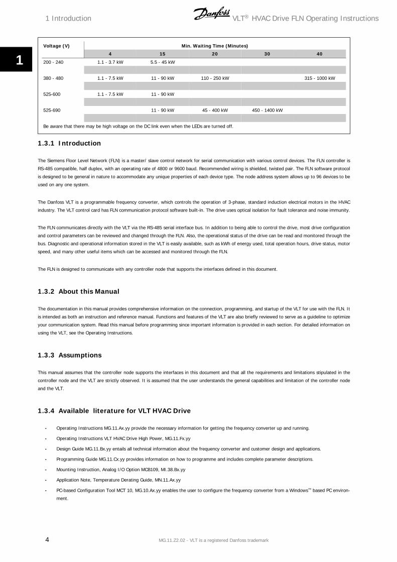
Voltage (V) Min. Waiting Time (Minutes)
4 15 20 30 40
200 - 240 1.1 - 3.7 kW 5.5 - 45 kW
380 - 480 1.1 - 7.5 kW 11 - 90 kW 110 - 250 kW 315 - 1000 kW
525-600 1.1 - 7.5 kW 11 - 90 kW
525-690 11 - 90 kW 45 - 400 kW 450 - 1400 kW
Be aware that there may be high voltage on the DC link even when the LEDs are turned off.
1.3.1 Introduction
The Siemens Floor Level Network (FLN) is a master/ slave control network for serial communication with various control devices. The FLN controller is
RS-485 compatible, half duplex, with an operating rate of 4800 or 9600 baud. Recommended wiring is shielded, twisted pair. The FLN software protocol
is designed to be general in nature to accommodate any unique properties of each device type. The node address system allows up to 96 devices to be
used on any one system.
The Danfoss VLT is a programmable frequency converter, which controls the operation of 3-phase, standard induction electrical motors in the HVAC
industry. The VLT control card has FLN communication protocol software built-in. The drive uses optical isolation for fault tolerance and noise immunity.
The FLN communicates directly with the VLT via the RS-485 serial interface bus. In addition to being able to control the drive, most drive configuration
and control parameters can be reviewed and changed through the FLN. Also, the operational status of the drive can be read and monitored through the
bus. Diagnostic and operational information stored in the VLT is easily available, such as kWh of energy used, total operation hours, drive status, motor
speed, and many other useful items which can be accessed and monitored through the FLN.
The FLN is designed to communicate with any controller node that supports the interfaces defined in this document.
1.3.2 About this Manual
The documentation in this manual provides comprehensive information on the connection, programming, and startup of the VLT for use with the FLN. It
is intended as both an instruction and reference manual. Functions and features of the VLT are also briefly reviewed to serve as a guideline to optimize
your communication system. Read this manual before programming since important information is provided in each section. For detailed information on
using the VLT, see the Operating Instructions.
1.3.3 Assumptions
This manual assumes that the controller node supports the interfaces in this document and that all the requirements and limitations stipulated in the
controller node and the VLT are strictly observed. It is assumed that the user understands the general capabilities and limitation of the controller node
and the VLT.
1.3.4 Available literature for VLT HVAC Drive
- Operating Instructions MG.11.Ax.yy provide the necessary information for getting the frequency converter up and running.
- Operating Instructions VLT HVAC Drive High Power, MG.11.Fx.yy
- Design Guide MG.11.Bx.yy entails all technical information about the frequency converter and customer design and applications.
- Programming Guide MG.11.Cx.yy provides information on how to programme and includes complete parameter descriptions.
- Mounting Instruction, Analog I/O Option MCB109, MI.38.Bx.yy
- Application Note, Temperature Derating Guide, MN.11.Ax.yy
- PC-based Configuration Tool MCT 10, MG.10.Ax.yy enables the user to configure the frequency converter from a Windows™ based PC environ-
ment.
1 Introduction VLT® HVAC Drive FLN Operating Instructions
4 MG.11.Z2.02 - VLT is a registered Danfoss trademark
1

- Danfoss VLT® Energy Box software at www.danfoss.com/BusinessAreas/DrivesSolutions then choose PC Software Download
- VLT® VLT HVAC Drive Drive Applications, MG.11.Tx.yy
- Operating Instructions VLT HVAC Drive Profibus, MG.33.Cx.yy.
- Operating Instructions VLT HVAC Drive Device Net, MG.33.Dx.yy
- Operating Instructions VLT HVAC Drive BACnet, MG.11.Dx.yy
- Operating Instructions VLT HVAC Drive LonWorks, MG.11.Ex.yy
- Operating Instructions VLT HVAC Drive Metasys, MG.11.Gx.yy
- Operating Instructions VLT HVAC Drive FLN, MG.11.Zx.yy
- Output Filter Design Guide, MG.90.Nx.yy
- Brake Resistor Design Guide, MG.90.Ox.yy
x = Revision number
yy = Language code
Danfoss technical literature is available in print from your local Danfoss Sales Office or online at:
www.danfoss.com/BusinessAreas/DrivesSolutions/Documentations/Technical+Documentation.htm
1.3.5 Abbreviations and standards
Abbreviations: Terms: SI-units: I-P units:a Acceleration m/s2 ft/s2
AWG American wire gauge Auto Tune Automatic Motor Tuning
°C Celsius I Current A Amp
ILIM Current limit Joule Energy J = N∙m ft-lb, Btu°F Fahrenheit FC Frequency Converter f Frequency Hz Hz
kHz Kilohertz kHz kHzLCP Local Control Panel mA Milliampere ms Millisecond min Minute MCT Motion Control Tool
M-TYPE Motor Type Dependent Nm Newton Metres in-lbsIM,N Nominal motor current fM,N Nominal motor frequency PM,N Nominal motor power UM,N Nominal motor voltage par. Parameter PELV Protective Extra Low Voltage Watt Power W Btu/hr, hp
Pascal Pressure Pa = N/m² psi, psf, ft of waterIINV Rated Inverter Output Current RPM Revolutions Per Minute SR Size Related T Temperature C Ft Time s s,hr
TLIM Torque limit U Voltage V V
Table 1.1: Abbreviation and standards table .
1.3.6 HP/kW conversion
A conversion index for determining kW and HP ratings is shown below.
VLT® HVAC Drive FLN Operating Instructions 1 Introduction
MG.11.Z2.02 - VLT is a registered Danfoss trademark 5
1

kW HP kW HP0.25 0.33 45 600.37 0.5 55 750.55 0.75 75 1000.75 1.0 90 1251.1 1.5 110 1501.5 2.0 132 1752.2 3.0 160 2003.0 4.0 200 3004.0 5.0 250 3505.5 7.5 315 3507.5 10 355 45011 15 400 50015 20 450 600
18.5 25 22 30 30 40 37 50
1 Introduction VLT® HVAC Drive FLN Operating Instructions
6 MG.11.Z2.02 - VLT is a registered Danfoss trademark
1

2 VLT Functional Features
The FLN protocol built into the VLT frequency converter allows programming of numerous features and monitoring of the drive via the serial bus and the
standard RS-485 port. The VLT also has the capability to control closed or open loop systems on its own and has been designed specifically for HVAC
applications. Always accessible in real-time are the system status, what the motor and drive are doing, and if there are any problems. The VLT continuously
monitors all aspects of motor and drive status and issues alarms or warnings for adverse conditions. The FLN interacts with the drive based upon a point
map database and the selected interface strategy. Many, but not all, drive features are accessible through the point map. See the Operating Instruc-
tions for more drive details. Table Point Mapping lists the map points and Table Point database definitions supplies definitions. Below is a review of some
frequently used drive features and the associated point map numbers.
2.1.1 Drive Operation (03-14)
These points provide the FLN with operational status information such as output frequency, motor current, output voltage, power and energy. The run
time in hours that power has been supplied to the motor is also stored for display, along with cumulative energy used in kWh.
2.1.2 Motor and Drive Thermal Protection (15, 16, 18)
The motor and drive are protected against thermal overload. The percentage of thermal load is displayed. Point 18 indicates if either the motor or drive
thermal limit has been exceeded.
2.1.3 Set-up 1-4 and Day/Night operation (17, 29)
In the FLN system it is not recommended to operate in multible set-up. The drive should remain in Set-up 1 at all times.
The drive is capable of maintaining four independent program set-ups. Each set-up supports independent point map configurations. Seasonal changes,
various acceleration or deceleration rates, or other operation modes can be accommodated. Point 17 indicates which setup is active. The set-up change
is programmed through the drive’s keypad or digital I/Os. Day/night operation is implemented in the point map (29).
2.1.4 Current Monitoring and Limits (19)
The maximum current that the drive provides to the motor can be limited. This tends to limit the torque that can be produced by the motor. Data point
19 indicates if the motor is operating at that current limit.
2.1.5 Direction of Rotation (22)
The drive responds to serial commands to reverse direction of the motor. The drive can safely reverse motor rotation while in operation. Many applications
benefit from this ability, such as vane axial fans reversed for smoke extraction or cooling towers for deicing. par. 8-54 Reversing Select, must be set to
serial communication for point 22 to command the feature.
2.1.6 Start/Stop (23)
To run the drive from the FLN or in Auto mode from the drive‘s digital control terminals, a start command must be given at data point 23. When a stop
command is given at this point, the drive will only run in Hand mode.
2.1.7 Ramp Select (24)
Datapoint 24 selects the active ramp.
VLT® HVAC Drive FLN Operating Instructions 2 VLT Functional Features
MG.11.Z2.02 - VLT is a registered Danfoss trademark 7
2
2.1.8 Freeze Mode (25, 26)
If desired, the frequency of the drive can be frozen at its present value. The mode is indicated by data point 25. It is an option available when serial
interface is lost.
2.1.9 Coast (27, 28)
The coast command (28) shuts down the inverter and makes the motor freewheeling, which normally brings it to stand still. The drive cannot be restarted
in any mode before the coast command is removed. It is, therefore, often used as a safety interlock. Data point 27 indicates when the drive is coasted.
2.1.10 Motor Ramp-up and Ramp-down Rate (31, 32)
The time to accelerate or decelerate the drive between 0 Hz and the motor’s nominal frequency can be programmed. The drive is capable of settings
between one to 3600 seconds (one hour). Only Ramp1 is accessible from the FLN network.
2.1.11 Hand/Auto Modes (34)
The SEL HND.AUTO shows which mode the drive is in. The drive can be commanded into either Hand or Auto mode by pressing the respective keys on
the keypad of the drive. Hand mode disables any programmed control strategies and allows the drive keypad to be used to set the drive speed. The only
serial communication command that can override Hand mode is data point 28, CMD COAST.
2.1.12 CMD RUN STOP (35)
Set data point 35 to ON to run the drive from the FLN with default drive parameter settings. In the OFF mode, the drive will run only in Hand mode or
in Auto mode from the drive‘s digital control terminals. par. 8-53 Start Select, controls the interaction of point 35 and the digital run command.
2.1.13 Bus Functions (36, 37)
The amount of time the drive will wait between communication packets is programmable. If the time is exceeded, the drive will assume serial commu-
nication has stopped and respond with programmable choices. The drive can ignore the loss, freeze its current output, stop, run at a predetermined jog
frequency, run at maximum output frequency or stop and trip while issuing an alarm. Wait time is selected at point 36 and the function after a timeout
at point 37. See descriptions for par. 8-03 Control Timeout Time and par. 8-04 Control Timeout Function in the VLT HVAC Drive Programming Guide.
2.1.14 Jog Frequency and Command (38, 39)
The Jog Frequency can be set by data point 38. Setting data point 39 to [On] will cause the frequency converter to send the Jog Frequency to the motor.
2.1.15 Relay Out 1, 2 (40, 41, 43, 44)
Two programmable relay outputs (Form C, 240 VAC, 2 Amp) are available. These can be triggered through the serial bus by command points 40 and 41.
This allows the FLN to utilize the drive’s built-in relays as additional network programmable relays. The data points 43 and 44 indicate whether the relay
is triggered or not (On/Off). Parameters 5-40.0 and 5-40.1, Function Relay 1 and Function Relay 2, must be set to [45] Bus controlled, [46] Bus controlled
1, if timeout or [47] Bus controlled 0, if timeout.
2.1.16 PID Control Functions (61-65)
The VLT has a sophisticated built-in proportional, integral, derivative (PID) controller. The PID controller is activated by setting par. 1-00 Configuration
Mode, to Closed loop through the drive’s keypad.
2 VLT Functional Features VLT® HVAC Drive FLN Operating Instructions
8 MG.11.Z2.02 - VLT is a registered Danfoss trademark
2

The PID controller in the VLT supports two feedback values and two setpoints. The feedback can be received in the form of network bus signals and/or
standard 0-10 V transmitters. The 2 set-point controller is capable of controlling return fans based on a fixed differential flow, secondary pumping systems,
and so on. This can be used to supplement the BMS system to save on points or capacity. For details on use of the two feedback/setpoint feature, refer
to the Operating Instructions. Data points 43 and 44 show the status of an FLN command to the drive.
The points PI GAIN and PI TIME are gain parameters similar to the P and I gains in the FLN TECs. The Danfoss PI loop is structured differently than the
Siemens loop, so there is not a one-to-one correspondence between the gains. The following formulas allow translation between Danfoss and Siemens
gains.
Converting from Danfoss PI gains to Siemens P and I gains:
P GainSIEMENS = PI GainDANFOSS × 0.0015I GainSIEMENS =
PI GainDANFOSSPI Time DANFOSS
× 0.0015
Converting from Siemens P and I gains to Danfoss PI gains:
PI GainDANFOSS = P GainSIEMENS × 667PI Time DANFOSS =
P GainSIEMENSI GainSIEMENS
× 667
2.1.17 Sleep Mode (59)
Sleep mode automatically stops the drive when demand is low over a period of time. When the system demand increases, the drive restarts the motor
to reach the desired output. Sleep mode has great energy savings potential and saves wear and tear on equipment. Unlike a setback timer, the drive is
always available to run when a preset “wakeup” demand is reached. See parameter group 22-4* Sleep Mode and 22-2* No-Flow Detection in the VLT
HVAC Drive Programming Guide for more detail.
2.1.18 Terminals 53, 54, (87-88)
Two analog voltage/current input terminals 53 and 54 (0-10 VDC)/(0-20 mA) are provided for reference or feedback signals. The applied electrical signal
can be read by data points 87 to 88 in volts and mA. This can be very useful during commissioning to calibrate transmitters. This can also be used to
convert any other analog transmitter in the installation into a digital bus signal, even if the signal is not used by the drive. In this case, the input terminal
should be programmed to No Function so it does not influence the operation of the drive.
2.1.19 Warnings and Alarms (90-94)
The drive displays a warning or tripped by a fault condition. It also can retrieve the last warning or fault trip for display. The drive can be reset through
the FLN serial bus to resume normal drive operation.
2.1.20 Error Status (99)
Data point 99 is implemented in the point map but is not used in this application.
VLT® HVAC Drive FLN Operating Instructions 2 VLT Functional Features
MG.11.Z2.02 - VLT is a registered Danfoss trademark 9
2

3 VLT Network Strategies VLT® HVAC Drive FLN Operating Instructions
10 MG.11.Z2.02 - VLT is a registered Danfoss trademark
3

3 VLT Network Strategies
The VLT has its own internal PID closed loop controller. This can be turned on or off, depending on the requirements of the control strategy. A brief
summary of possibilities follows. This is meant to illustrate possibilities rather than be all-inclusive. An actual application may combine features from a
more than one of these strategies.
3.1.1 Strategy one
FLN Function – Monitor drive operation
FC Control – From a conventional, hardwired system
FC Mode – Open Loop.
The VLT follows hard-wired run/stop signals. An external, hard-wired PID controller provides the drive with a speed reference signal. The FLN monitors
the operation of the drive without control function.
Network Inputs to the VLT:
Because the FLN is simply monitoring the operation of the drive, it provides no inputs.
Network Outputs from the VLT:
The following points are monitored by the FLN to indicate system status. This list could be expanded or shortened, depending on the requirements of
the system.
03 FREQ OUTPUT
08 POWER 10 KWH
23 STOP.RUN
92 ALARM
3.1.2 Strategy two
FLN Function – Control all aspects of frequency converter operation
FC Control – From FLN network
FC Mode – Open Loop
The frequency converter follows run/stop and speed reference signals from the FLN. The FLN receives the feedback signal from the controlled system,
compares this to a set-point value, and uses its own PID control loop to determine the required drive speed.
Network Inputs to the frequency converter:
The following drive points might be controlled by the FLN.
Speed Command:
53 CMD REF This is the speed reference command. This is set as a percentage of the drive’s reference range, determined
by par. 3-02 Minimum Reference and par. 3-03 Maximum Reference. Setting point 53 to 0 gives the drive a reference command
equal to the value stored in par. 3-03 Maximum Reference. Setting point 53 to 16384 gives the drive a reference command
equal to the value stored in par. 3-03 Maximum Reference. Intermediate values for point 53 change the reference linearly
between these two values.
NB!
In general, any other reference signal is added to the bus reference. Disable all other drive reference inputs when using a bus reference
to control drive speed.
Start/Stop Command:
To give a start command from the FLN, the following points must be set. The frequency converter can also respond to discrete run/stop control signals
that are hard wired to its control terminals. The point used to stop the frequency converter through the FLN determines the capability of these discrete
command signals.
VLT® HVAC Drive FLN Operating Instructions 3 VLT Network Strategies
MG.11.Z2.02 - VLT is a registered Danfoss trademark 11
3

28 CMD COAST In most cases, it is necessary to set this point to [NO] to make the drive run. If this is set to [COAST]
while the VLT is running, the drive will shut off immediately and the motor will coast to a stop. When
set to [COAST], the lower right corner of the drive display shows Coast. The drive will not start in either
HAND mode or through discrete control signals until point 28 is set to [NO]. VLT par. 8-50 Coasting
Select, can defeat this. See the VLT HVAC Drive Operating Instructions for details. Because point 28
can keep the drive from operating in any mode, this is commonly used to provide a safety interlock
function.
35 RUN ENABLE In most cases, it is necessary to set this point [ON] to make the drive run. If this is set to [OFF] while
the drive is running, the drive will decelerate to a stop. When set to [OFF], the lower right corner of
the display shows STAND BY. When OFF, the drive can be started in HAND mode from the keypad. It
can also be started using a hard-wired discrete run command, as when par. 8-53 Start Select, is set
to digital input.
Network Outputs from the VLT:
The points listed in Strategy One are commonly used.
3.1.3 Strategy three
FLN Function – Monitor frequency converter operation
FC Control – From a hard-wired system, including system feedback
FC Mode – Closed Loop
The frequency converter follows hard-wired run/stop signals. It uses its internal PID controller to control motor speed. The feedback signal is hard wired
to the analog input and the set-point is programmed into the drive. The FLN is used to monitor the status of the FC and the value of the PID controller
set-point and feedback.
Network Inputs to the frequency converter:
Because the FLN is simply monitoring the operation of the frequency converter, it provides no inputs.
Network Outputs from the frequency converter:
In addition to the points listed in Strategy One, it may be useful to monitor the following points related to the operation of the PID controller.
Feedback:
53 CMD REF This is the set-point for the PID controller. Please consult the VLT HVAC Drive Design Guide for further information
on how to set up the PID controller.
65 FEEDBACK This is the value of the feedback signal in % for the PID controller.
3.1.4 Strategy four
FLN Function – Provide the frequency converter with set-point and feedback values using the PID controller to determine motor speed
FC Control – From the FLN
FC Mode – Closed Loop
The frequency converter follows run/stop signals from the FLN. The FLN receives the feedback signal from the controlled system. It sends this and the
desired set-point to the PID controller. The frequency converter compares the feedback signal with the set-point and adjusts the speed of the FC ac-
cordingly.
3 VLT Network Strategies VLT® HVAC Drive FLN Operating Instructions
12 MG.11.Z2.02 - VLT is a registered Danfoss trademark
3

Network inputs to the frequency converter:
In addition to start/stop control, which was discussed in Strategy Two, the FLN provides the frequency converter with feedback and set-point information
using the following points.
Feedback:
69 BUS FBK 1 A value of -163.83 % represents the minimum feedback signal. A value of +163.83 % represents the maximum
feedback signal. This should be the feedback used if only one feedback signal is supplied to the frequency converter.
NB!
If the frequency converter terminal 53 is programmed by means of par. 20-00 Feedback 1 Source, for feedback, any signal applied to
terminal 54 is added to value provided at point 53 CMD REF. Therefore, it is generally advisable not to program par. 20-00 Feedback
1 Source for feedback.
Example:
In a cooling tower application, the feed-back signal comes from a temperature sensor with a range of 40 °F to 140 °F. To unbundle BUS FBK 2 (point
70) for the temperature sensor:
1. Set par. 20-13 Minimum Reference/Feedb. to 40.
2. Set par. 20-14 Maximum Reference/Feedb. to 140.
3. Intercept = 40 (since the minimum feedback value is 40)
4. Slope can be calculated as follows:
Slope = (Desired Range) × (Slope of Existing Point)Range of Existing Point = (140 − 40) × 0.1
16383 = 0.00061
Set-point:
66 SET-POINT 1 This is the PID controller’s set-point, expressed in the units that were chosen in par. 20-02 Feedback 1 Source
Unit. It can be set to any value between par. 3-02 Minimum Reference and par. 3-03 Maximum Reference. If an
attempt is made to set point 69 to a value outside of this range, the set-point will not be changed. SET-POINT 1 can
also be programmed using par. 20-21 Setpoint 1.
67 SET-POINT 2 This PID controller's set-point is used for applications, where multible feedback signals will be compared to inde-
pendent set-points. Refer to the VLT HVAC Drive Design Guide for more details. SET-POINT 2 is expressed in the
units selected in par. 3-03 Maximum Reference. If an attempt is made to assign point 70 to a value outside of this
range, the set-point will not change. Set-point 2 can also be programmed using par. 20-22 Setpoint 2.
PID Controller Adjustments:
The following points adjust the operation of the PID control loop. They are generally set during start-up and only adjusted if changes in the system require
it. These values can also be set using parameters. See the VLT HVAC Drive Programming Guide for more details.
61 PI START FREQ
(par. 20-83 PID Start Speed
[Hz])
This sets the frequency to which the FC will accelerate following a start command. After it reaches this fre-
quency, the frequency converter will activate its PID controller. Point 61 can have a value between the drive’s
minimum frequency (as set in par. 4-12 Motor Speed Low Limit [Hz]) and its maximum frequency (as set in
par. 4-13 Motor Speed High Limit [RPM]). If an attempt is made to set point 61 to a value outside of this range,
the drive value will not change.
63 PI GAIN (par. 20-93 PID
Proportional Gain)
This sets the value of proportional gain for the PID controller. It can have a value between 0 and 10.
Network Outputs from the VLT:
The points listed in Strategy One are commonly used.
VLT® HVAC Drive FLN Operating Instructions 3 VLT Network Strategies
MG.11.Z2.02 - VLT is a registered Danfoss trademark 13
3

4 VLT Special Functions VLT® HVAC Drive FLN Operating Instructions
14 MG.11.Z2.02 - VLT is a registered Danfoss trademark
4

4 VLT Special Functions
4.1.1 Special functions
In addition to the control strategies described above, the frequency converter provides additional control flexibility to allow it to integrate into special
control system requirements. The following are just a few examples.
4.1.2 Analog input monitoring
Points 87 and 88 can be used to monitor the value of the analog control signals applied to terminals 53 and 54. These points are active even when NO
FUNCTION is programmed for the analog input of the drive. As a result, it is possible to use the frequency converter analog inputs as analog input for
the FLN.
4.1.3 Drive relay control
While relay 1 and 2 in the FC usually provide drive status indications, these indications are generally not needed, when the drive is connected to a FLN
network. In some applications, it can be useful to have the FLN control these relays. For example, by controlling one of the relays, the FLN could select
the active pump in a pump sequencing system. For the FLN to control a drive relay, the appropriate FC parameter (5-40.0 or 5-40.1) must be set to [Bus
Control]. Setting point 40 or 41 to [On] will then activate the corresponding relay.
VLT® HVAC Drive FLN Operating Instructions 4 VLT Special Functions
MG.11.Z2.02 - VLT is a registered Danfoss trademark 15
4

5 Network Connection VLT® HVAC Drive FLN Operating Instructions
16 MG.11.Z2.02 - VLT is a registered Danfoss trademark
5

5 Network Connection
5.1.1 Network connection
Connect the frequency converter to the RS-485 network as follows (see also diagram):
1. Connect signal wires to terminal 68 (P+) and terminal 69 (N-) on the main control board of the frequency converter.
2. Connect the cable screen to the cable clamps.
NB!
Screened, twisted-pair cables are recommended in or-
der to reduce noise between conductors.
Illustration 5.1: Network Terminal Connection
����
����
���
Illustration 5.2: Control card terminals
5.1.2 Frequency converter hardware setup
Use the terminator dip switch on the main control board of the frequency
converter to terminate the RS-485 bus.
Illustration 5.3: Terminator Switch Factory Setting
The factory setting for the dip switch is OFF.
5.1.3 Electrical installation
NB!
Electrical installation: Please see VLT HVAC Drive Operating Instructions, MG.11.Ax.yy.
x=version ; yy=language code.
VLT® HVAC Drive FLN Operating Instructions 5 Network Connection
MG.11.Z2.02 - VLT is a registered Danfoss trademark 17
5

6 Parameters VLT® HVAC Drive FLN Operating Instructions
18 MG.11.Z2.02 - VLT is a registered Danfoss trademark
6

6 Parameters
6.1.1 Parameter settings
The frequency converter has a unique FLN address, which is transmitted over the RS-485 serial bus. The network will recognize the FC, which may then
be programmed for setup options. The parameters listed in the table below need to be set for each FC on the FLN network. FLN communication related
parameters can only be set by using the LCP.
NB!
As a minimum, it is required to set par. 8-30 Protocol to FLN; par. 8-31 Address, to the proper address and par. 8-32 Baud Rate to the
proper baud rate. (See VLT HVAC Drive Programming Guide).
Par. 8-50 Coasting Select through par. 8-56 Preset Reference Select are options that select control of the drive through the digital and/or the FLN serial
port.
Parameter Default Desired setting
*par. 8-03 Control Timeout Time 0
*par. 8-04 Control Timeout Function 0ff
*par. 8-30 Protocol FC FLN
*par. 8-31 Address 1 through 98
*par. 8-32 Baud Rate 9600 4800 or 9600
**par. 8-50 Coasting Select Logic or
**par. 8-52 DC Brake Select Logic or
**par. 8-53 Start Select Logic or
**par. 8-54 Reversing Select Digital input
**par. 8-55 Set-up Select Logic or
**par. 8-56 Preset Reference Select Logic or
Table 6.1: Frequency converter parameter settings
* Minimum parameters, which must be set to operate the frequency converter via the FLN serial interface.
** When [Digital input] or [Logic or] is selected, digital inputs may interfere with serial bus commands. The setting [Serial communication] allows serial
bus commands to be carried out only. See the VLT HVAC Drive Programming Guide for detailed descriptions.
NB!
The frequency converter can store preset references programmed in parameters 3-10.0 through 3-10.7, Preset Reference (1-8). To
avoid these values modifying serial bus references, set par. 3-04 Reference Function to [External/Preset]. See VLT HVAC Drive Pro-
gramming Guide for detailed descriptions.
VLT® HVAC Drive FLN Operating Instructions 6 Parameters
MG.11.Z2.02 - VLT is a registered Danfoss trademark 19
6
7 Start-up and Troubleshooting VLT® HVAC Drive FLN Operating Instructions
20 MG.11.Z2.02 - VLT is a registered Danfoss trademark
7

7 Start-up and Troubleshooting
7.1 Start-up
7.1.1 Start-up of FLN control
This procedure assumes that the frequency converter has been installed properly and is operational in Hand control mode. It also assumes the Siemens
FLN data bus is connected to an operational controller. Start the FC in accordance with the following procedure.
1. Ensure that the assumptions in this procedure are correct.
2. Check that the network connections are securely fastened in accordance with Figure Network Terminal Connection
Verify compliance with all safety requirements listed in this manual.
3. Apply power to the frequency converter.
4. Ensure that the minimum settings listed in Table 6.1 Frequency converter parameter settings are selected.
5. Ensure that the switch positions in Illustration 5.3 Terminator Switch Factory Setting are set correctly.
6. Optional settings may be changed to meet or enhance frequency converter operation, depending on the application requirements.
7. For FLN control of the drive, press the AUTO START key on the LCP. FC operation can then be controlled through the host network device in
accordance with its operation instructions.
NB!
Default setting for point number 35, CMD RUN STOP, is [OFF]. Drive will not operate until Run Enable [ON] signal is given through
serial communication network.
7.2 Troubleshooting
7.2.1 Faults, warnings and alarms
A stopped motor may start unexpectedly if faults occur in electronics of drive, or if an active fault clears, such as a fault in supply AC
line, fault in motor connection or overload.
The frequency converter output faults, warnings and alarms on the FLN serial bus in a numerical code. The code numbers are described in Table Faults,
Warnings and Alarms Description. The Reset key is used for manually resetting the drive after an alarm (fault trip). In this case, the top line of the display
will show TRIP (RESET). If the top line of the display shows TRIP (AUTO START), the drive will automatically restart. If the top line of the display shows
TRIPLOCK (DISC. MAINS), input power to the drive must be cycled off and on again before the trip can be reset.
Refer to the VLT HVAC Drive Operating Instructions for detailed descrip-
tions.
7.2.2 Alarms and warnings
A warning or an alarm is signalled by the relevant LED on the front of the frequency converter and indicated by a code on the display.
A warning remains active until its cause is no longer present. Under certain circumstances operation of the motor may still be continued. Warning messages
may be critical, but are not necessarily so.
VLT® HVAC Drive FLN Operating Instructions 7 Start-up and Troubleshooting
MG.11.Z2.02 - VLT is a registered Danfoss trademark 21
7

In the event of an alarm, the frequency converter will have tripped. Alarms must be reset to restart operation once their cause has been rectified. This
may be done in four ways:
1. By using the [RESET] control button on the LCP control panel.
2. Via a digital input with the “Reset” function.
3. Via serial communication/optional fieldbus.
4. By resetting automatically using the [Auto Reset] function, which is a default setting for frequency converter. see par. 14-20 Reset Mode in VLT
HVAC Drive Programming Guide, MG.11.Cx.yy
NB!
After a manual reset using the [RESET] button on the LCP, the [AUTO ON] button must be pressed to restart the motor.
If an alarm cannot be reset, the reason may be that its cause has not been rectified, or the alarm is trip-locked (see also table on following page).
Alarms that are trip-locked offer additional protection, means that the mains supply must be switched off before the alarm can be reset. After being
switched back on, the frequency converter is no longer blocked and may be reset as described above once the cause has been rectified.
Alarms that are not trip-locked can also be reset using the automatic reset function in par. 14-20 Reset Mode (Warning: automatic wake-up is possible!)
If a warning and alarm is marked against a code in the table on the following page, this means that either a warning occurs before an alarm, or it can
be specified whether it is a warning or an alarm that is to be displayed for a given fault.
This is possible, for instance, in par. 1-90 Motor Thermal Protection. After an alarm or trip, the motor carries on coasting, and the alarm and warning
flash on the frequency converter. Once the problem has been rectified, only the alarm continues flashing.
7 Start-up and Troubleshooting VLT® HVAC Drive FLN Operating Instructions
22 MG.11.Z2.02 - VLT is a registered Danfoss trademark
7

No. Description Warning Alarm/Trip Alarm/Trip Lock Parameter Reference1 10 Volts low X 2 Live zero error (X) (X) par. 6-01 Live Zero Time-
out Function3 No motor (X) par. 1-80 Function at
Stop4 Mains phase loss (X) (X) (X) par. 14-12 Function at
Mains Imbalance5 DC link voltage high X 6 DC link voltage low X 7 DC over voltage X X 8 DC under voltage X X 9 Inverter overloaded X X 10 Motor ETR over temperature (X) (X) par. 1-90 Motor Thermal
Protection11 Motor thermistor over temperature (X) (X) par. 1-90 Motor Thermal
Protection12 Torque limit X X 13 Over Current X X X 14 Earth fault X X X 15 Incomp. HW X X 16 Short Circuit X X 17 Control word timeout (X) (X) par. 8-04 Control Time-
out Function23 Internal fans 24 External fans 25 Brake resistor short-circuited X 26 Brake resistor power limit (X) (X) par. 2-13 Brake Power
Monitoring27 Brake chopper short-circuited X X 28 Brake check (X) (X) par. 2-15 Brake Check29 Power board over temp X X X 30 Motor phase U missing (X) (X) (X) par. 4-58 Missing Motor
Phase Function31 Motor phase V missing (X) (X) (X) par. 4-58 Missing Motor
Phase Function32 Motor phase W missing (X) (X) (X) par. 4-58 Missing Motor
Phase Function33 Inrush fault X X 34 Fieldbus communication fault X X 35 Option fault X 36 Mains failure 38 Internal fault X X 40 Overload T27 41 Overload T29 42 Overload X30/6-7 47 24 V supply low X X X 48 1.8 V supply low X X 49 Speed limit 50 AMA calibration failed X 51 AMA check Unom and Inom X 52 AMA low Inom X 53 AMA motor too big X 54 AMA motor too small X 55 AMA parameter out of range X 56 AMA interrupted by user X 57 AMA timeout X 58 AMA internal fault X X 59 Current limit X 60 External interlock 62 Output Frequency at Maximum Limit X 65 Control Board Over-temperature X X X 66 Heat sink Temperature Low X 67 Option Configuration has Changed X 68 Safe Stop Activated X 70 Illegal FC configuration 80 Drive Initialised to Default Value X 92 No-Flow X X Par. 22-2*93 Dry Pump X X Par. 22-2*94 End of Curve X X Par. 22-5*95 Broken Belt X X Par. 22-6*96 Start Delayed X Par. 22-7*97 Stop Delayed X Par. 22-7*98 Clock Fault X Par. 0-7*
Table 7.1: Alarm/Warning code list
VLT® HVAC Drive FLN Operating Instructions 7 Start-up and Troubleshooting
MG.11.Z2.02 - VLT is a registered Danfoss trademark 23
7

No. Description Warning Alarm/Trip Alarm/Trip Lock Parameter Reference200 Fire Mode X Par. 24-0*201 Fire Mode was Active X Par. 0-7*202 Fire Mode Limits Exceeded X Par. 0-7*250 New spare part 251 New type code
Table 7.2: Alarm/Warning code list, continued..
(X) Dependent on parameter
LED indicationWarning yellowAlarm flashing red
Trip locked yellow and red
Alarm Word and Extended Status WordBit Hex Dec Alarm Word Warning Word Extended Status Word0 00000001 1 Brake Check Brake Check Ramping1 00000002 2 Pwr. Card Temp Pwr. Card Temp AMA Running2 00000004 4 Earth Fault Earth Fault Start CW/CCW3 00000008 8 Ctrl.Card Temp Ctrl.Card Temp Slow Down4 00000010 16 Ctrl. Word TO Ctrl. Word TO Catch Up5 00000020 32 Over Current Over Current Feedback High6 00000040 64 Torque Limit Torque Limit Feedback Low7 00000080 128 Motor Th Over Motor Th Over Output Current High8 00000100 256 Motor ETR Over Motor ETR Over Output Current Low9 00000200 512 Inverter Overld. Inverter Overld. Output Freq High10 00000400 1024 DC under Volt DC under Volt Output Freq Low11 00000800 2048 DC over Volt DC over Volt Brake Check OK12 00001000 4096 Short Circuit DC Voltage Low Braking Max13 00002000 8192 Inrush Fault DC Voltage High Braking14 00004000 16384 Mains ph. Loss Mains ph. Loss Out of Speed Range15 00008000 32768 AMA Not OK No Motor OVC Active16 00010000 65536 Live Zero Error Live Zero Error 17 00020000 131072 Internal Fault 10V Low 18 00040000 262144 Brake Overload Brake Overload 19 00080000 524288 U phase Loss Brake Resistor 20 00100000 1048576 V phase Loss Brake IGBT 21 00200000 2097152 W phase Loss Speed Limit 22 00400000 4194304 Fieldbus Fault Fieldbus Fault 23 00800000 8388608 24 V Supply Low 24V Supply Low 24 01000000 16777216 Mains Failure Mains Failure 25 02000000 33554432 1.8V Supply Low Current Limit 26 04000000 67108864 Brake Resistor Low Temp 27 08000000 134217728 Brake IGBT Voltage Limit 28 10000000 268435456 Option Change Unused 29 20000000 536870912 Drive Initialised Unused 30 40000000 1073741824 Safe Stop Unused
Table 7.3: Description of Alarm Word, Warning Word and Extended Status Word
The alarm words, warning words and extended status words can be read out via serial bus or optional field-bus for diagnosis. See also par. 16-90 Alarm
Word, par. 16-92 Warning Word and par. 16-94 Ext. Status Word.
7 Start-up and Troubleshooting VLT® HVAC Drive FLN Operating Instructions
24 MG.11.Z2.02 - VLT is a registered Danfoss trademark
7

Poin
tno
.
6000
poin
tno
.D
escr
ipto
rFa
ctor
yde
faul
t(S
I)
Engr
.U
nit
(SI)
Slop
e(S
I)In
terc
ept
(SI)
On
text
Off
text
Rang
eM
axva
ue(S
I)
Min
valu
e(S
I)
Poin
tty
pe
Clas
sTy
pe(N
ote
1)
Read
Onl
yPa
r.N
o.
11
CTRL
AD
-D
RESS
0-
10
--
255
255
02
LAO
Yes
8-31
22
APPL
ICA-
TIO
N27
59-
10
--
1638
316
383
02
LAO
Yes
-
{3}
3FR
EQ O
UT-
PUT
0H
Z0,
10
--
1638
316
38,3
03
LAI
Yes
16-1
3
{4}
-PC
T O
UT-
PUT
0PC
T0,
01-1
63,8
3-
-32
767
163,
83-1
63,8
33
LAI
Yes
16-1
5
{5}
-REF
PCT
0PC
T0,
1-1
638,
3-
-32
767
1638
,3-1
638,
33
LAI
Yes
16-0
2{6
}6
CURRE
NT
0A
0,1
0-
-32
767
3276
,70
3LA
IYe
s16
-14
{7}
-CT
RL.C
RD.T
MP
0D
EG C
10
255
255
03
LAI
Yes
16-3
9
{8}
8PO
WER
KW
0KW
0,1
0-
-32
767
3276
,70
3LA
IYe
s16
-10
{9}
-PO
WER
HP
0H
P0,
10
--
3276
732
76,7
03
LAI
Yes
16-1
1{1
0}10
KWH
0KW
H1
0-
-10
2310
230
3LA
IYe
s15
-02
{11}
-M
WH
0M
WH
10
--
3276
732
767
03
LAI
Yes
15-0
2{1
2}12
RUN
TIM
E0
HR
40
--
3276
713
1068
03
LAI
Yes
15-0
1
{13}
13D
C BU
SVO
LT0
V1
0-
-40
9540
950
3LA
IYe
s16
-30
{14}
14O
UTP
UT
VOLT
0V
10
--
4095
4095
03
LAI
Yes
16-1
2
{15}
15M
OTO
RTH
ERM
0PC
T1
0-
-25
525
50
3LA
IYe
s16
-18
{16}
16D
RIV
ETH
ERM
0PC
T1
0-
-25
525
50
3LA
IYe
s16
-35
{17}
17AC
TIVE
SET
-U
P0
-1
0-
-25
525
50
3LA
IYe
s0-
10
{18}
-H
EATS
INK
TMP
0D
EG C
10
--
255
255
03
LAI
Yes
16-3
4
{19}
19CU
R.L
IM.S
TAT
OK
-1
0LI
MIT
OK
255
255
03
LDI
Yes
16-0
3 [1
4]
2020
OVR
D T
IME
0H
RS
10
--
255
255
02
LAO
No
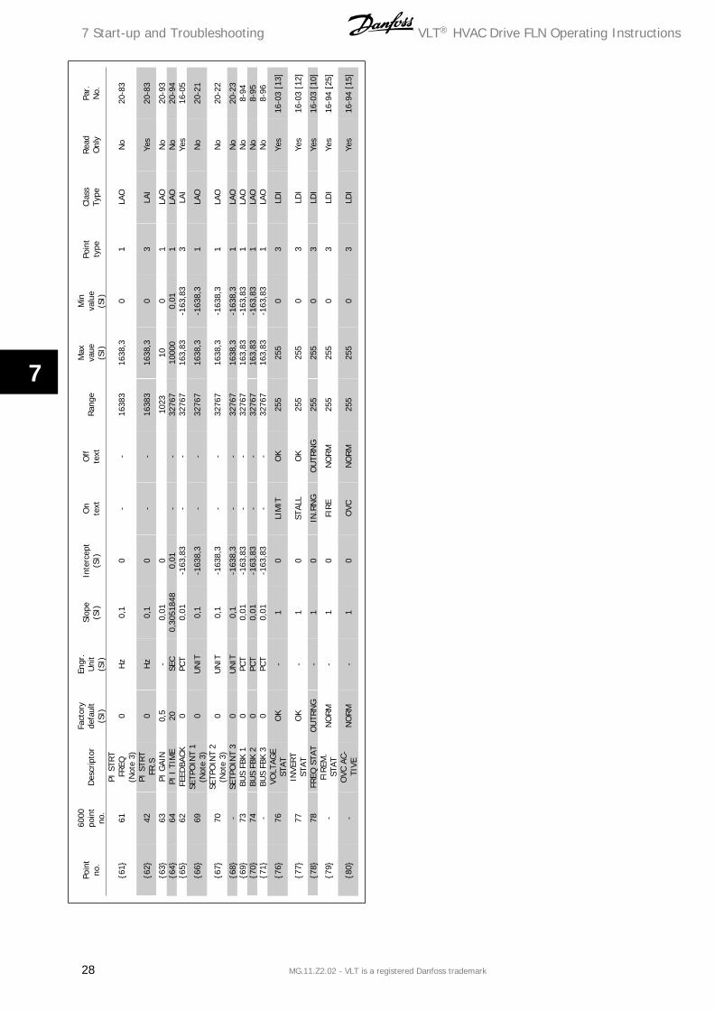
7.2
.3P
oin
t m
appi
ng
tabl
e
VLT® HVAC Drive FLN Operating Instructions 7 Start-up and Troubleshooting
MG.11.Z2.02 - VLT is a registered Danfoss trademark 25
7

Poin
tno
.
6000
poin
tno
.D
escr
ipto
rFa
ctor
yde
faul
t(S
I)
Engr
.U
nit
(SI)
Slop
e(S
I)In
terc
ept
(SI)
On
text
Off
text
Rang
eM
axva
ue(S
I)
Min
valu
e(S
I)
Poin
tty
peCl
ass
Type
Read
Onl
yPa
r.N
o.
{21}
21FW
D.R
EVFW
D-
10
REV
FWD
255
255
03
LDI
Yes
Not
e[3]
{22}
22CM
DFW
D.R
EVFW
D-
10
REV
FWD
255
255
01
LDO
No
CTW
[15
]
{23}
23RU
N.S
TOP
STO
P-
10
RUN
STO
P25
525
50
3LD
IYe
s16
-03
[11
]
{24}
-RAM
P SE
-LE
CTRAM
P1-
10
RAM
P2RAM
P125
525
50
1LD
ON
oCT
W [
09]
{25}
25FR
EEZE
OU
TO
FF-
10
ON
OFF
255
255
03
LDI
Yes
16-9
5 [1
4]
{26}
26CM
DFR
EEZE
OFF
-1
0O
NO
FF25
525
50
1LD
ON
oCT
W [
05]
{27}
27CO
ASTI
NG
OFF
-1
0O
FFCO
AST
255
255
03
LDI
Yes
16-0
0 [0
3]{2
8}28
CMD
CO
AST
OFF
-1
0O
FFCO
AST
255
255
01
LDO
No
CTW
[03
]
2929
DAY
.NIG
HT
(Not
e 2)
DAY
-1
0N
IGH
TD
AY25
525
50
1LD
ON
o-
{31}
31AC
CEL
TIM
E1
0* (
Not
e 4)
SEC
11
--
4095
3600
11
LAO
No
3-41
{32}
32D
ECEL
TIM
E1
0* (
Not
e 4)
SEC
11
--
4095
3600
11
LAO
No
3-42
{34}
34H
AND
.AU
TOAU
TO-
10
HAN
DAU
TO25
525
50
3LD
IYe
s16
-95
[01]
{35}
35CM
DRU
N.S
TOP
STO
P-
10
RUN
STO
P25
525
50
1LD
ON
oCT
W [
06]
{36}
36BU
S TI
ME-
OU
T0*
SEC
11
--
3276
718
000
11
LAO
No
8-03
{37}
37BU
S FU
NC-
TIO
N0
(Not
e 6)
-1
0-
-25
510
01
LAO
No
8-04
{38}
-JO
G F
REQ
10.0
HZ
0,1
0-
-16
383
1638
,30
1LA
ON
o3-
11{3
9}-
CMD
JO
GN
O-
10
YES
NO
255
255
01
LDO
No
CTW
[08
]
{40}
40CM
D.R
ELAY
1O
FF-
10
ON
OFF
255
255
01
LDO
No
CTW
[11
]
7 Start-up and Troubleshooting VLT® HVAC Drive FLN Operating Instructions
26 MG.11.Z2.02 - VLT is a registered Danfoss trademark
7

Poin
tno
.
6000
poin
tno
.D
escr
ipto
rFa
ctor
yde
faul
t(S
I)
Engr
.U
nit
(SI)
Slop
e(S
I)In
terc
ept
(SI)
On
text
Off
text
Rang
eM
axva
ue(S
I)
Min
valu
e(S
I)
Poin
tty
peCl
ass
Type
Read
Onl
yPa
r.N
o.
{41}
41CM
D.R
ELAY
2O
FF-
10
ON
OFF
255
255
01
LDO
No
CTW
[12
]
{42}
-CM
D A
O1
0PC
T0,
010
--
1638
316
3,83
01
LAO
No
6-53
{43}
43RE
LAY
1ST
ATO
FF-
10
ON
OFF
255
255
03
LDI
Yes
16-7
1 [0
4]
{44}
44RE
LAY
2ST
ATO
FF-
10
ON
OFF
255
255
03
LDI
Yes
16-7
1[03
]
{45}
-AO
1 ST
AT0
MA
0,01
0-
-40
9540
,95
03
LAI
Yes
16-6
5{4
6}-
DI
18 S
TAT
OFF
-1
0O
NO
FF25
525
50
3LD
IYe
s16
-60
[05]
{47}
-D
I 19
STA
TO
FF-
10
ON
OFF
255
255
03
LDI
Yes
16-6
0 [0
4]{4
8}-
DI
27 S
TAT
OFF
-1
0O
NO
FF25
525
50
3LD
IYe
s16
-60
[03]
{49}
-D
I 29
STA
TO
FF-
10
ON
OFF
255
255
03
LDI
Yes
16-6
0 [0
2]{5
0}-
DI
32 S
TAT
OFF
-1
0O
NO
FF25
525
50
3LD
IYe
s16
-60
[01]
{51}
-D
I 33
STA
TO
FF-
10
ON
OFF
255
255
03
LDI
Yes
16-6
0 [0
0]{5
2}52
AT S
PEED
OFF
REF
-1
0O
N.R
EFO
FFREF
255
255
03
LDI
Yes
16-0
3 [0
8]{5
3}53
CMD
REF
0PC
T0,
010
--
3276
720
00
1LA
ON
oRE
F
{54}
-AC
CEL
TIM
E2
0*SE
C1
1-
-40
9536
001
1LA
ON
o3-
51
{55}
-D
ECEL
TIM
E2
0*SE
C1
1-
-40
9536
001
1LA
ON
o3-
52
{56}
-BY
PASS
CMD
DRI
VE-
10
BYPA
SSD
RIV
E25
525
50
1LD
ON
o31
-00
{57}
-BY
PASS
STAT
0-
10
--
3276
732
767
03
LAI
Yes
31-1
0
{58}
-BO
STA
RTD
LY30
SEC
10
--
4095
300
1LA
ON
o31
-01
{59}
59SL
EEP
STA-
TUS
NO
-1
0SL
EEP
NO
255
255
03
LDI
Yes
[21]
{60}
-BO
TRIP
DLY
0SE
C1
0-
-40
9530
00
1LA
ON
o31
-02
VLT® HVAC Drive FLN Operating Instructions 7 Start-up and Troubleshooting
MG.11.Z2.02 - VLT is a registered Danfoss trademark 27
7
Poin
tno
.
6000
poin
tno
.D
escr
ipto
rFa
ctor
yde
faul
t(S
I)
Engr
.U
nit
(SI)
Slop
e(S
I)In
terc
ept
(SI)
On
text
Off
text
Ran
geM
axva
ue(S
I)
Min
valu
e(S
I)
Poin
tty
peCl
ass
Type
Read
Onl
yPa
r.N
o.
{61}
61PI
STR
TFR
EQ(N
ote
3)0
Hz
0,1
0-
-16
383
1638
,30
1LA
ON
o20
-83
{62}
42PI
STR
TFR
.S0
Hz
0,1
0-
-16
383
1638
,30
3LA
IYe
s20
-83
{63}
63PI
GAI
N0,
5-
0,01
0
10
2310
01
LAO
No
20-9
3{6
4}64
PI I
TIM
E20
SEC
0,30
5184
80,
01-
-32
767
1000
00,
011
LAO
No
20-9
4{6
5}62
FEED
BACK
0PC
T0,
01-1
63,8
3-
-32
767
163,
83-1
63,8
33
LAI
Yes
16-0
5
{66}
69SE
TPO
INT
1(N
ote
3)0
UN
IT0,
1-1
638,
3-
-32
767
1638
,3-1
638,
31
LAO
No
20-2
1
{67}
70SE
TPO
INT
2(N
ote
3)0
UN
IT0,
1-1
638,
3-
-32
767
1638
,3-1
638,
31
LAO
No
20-2
2
{68}
-SE
TPO
INT
30
UN
IT0,
1-1
638,
3-
-32
767
1638
,3-1
638,
31
LAO
No
20-2
3{6
9}73
BUS
FBK
10
PCT
0,01
-163
,83
--
3276
716
3,83
-163
,83
1LA
ON
o8-
94{7
0}74
BUS
FBK
20
PCT
0,01
-163
,83
--
3276
716
3,83
-163
,83
1LA
ON
o8-
95{7
1}-
BUS
FBK
30
PCT
0,01
-163
,83
--
3276
716
3,83
-163
,83
1LA
ON
o8-
96
{76}
76VO
LTAG
EST
ATO
K-
10
LIM
ITO
K25
525
50
3LD
IYe
s16
-03
[13]
{77}
77IN
VERT
STAT
OK
-1
0ST
ALL
OK
255
255
03
LDI
Yes
16-0
3 [1
2]
{78}
78FR
EQ S
TAT
OU
TRN
G-
10
IN.R
NG
OU
TRN
G25
525
50
3LD
IYe
s16
-03
[10]
{79}
-FI
REM
.ST
ATN
ORM
-1
0FI
RE
NO
RM
255
255
03
LDI
Yes
16-9
4 [2
5]
{80}
-O
VC A
C-TI
VEN
ORM
-1
0O
VCN
ORM
255
255
03
LDI
Yes
16-9
4 [1
5]
7 Start-up and Troubleshooting VLT® HVAC Drive FLN Operating Instructions
28 MG.11.Z2.02 - VLT is a registered Danfoss trademark
7

Poin
tno
.
6000
poin
tno
.D
escr
ipto
rFa
ctor
yde
faul
t(S
I)
Engr
.U
nit
(SI)
Slop
e(S
I)In
terc
ept
(SI)
On
text
Off
text
Rang
eM
axva
ue(S
I)
Min
valu
e(S
I)
Poin
tty
peCl
ass
Type
Read
Onl
yPa
r.N
o.
{81}
81RA
MPI
NG
NO
RM-
10
RAM
PN
ORM
255
255
03
LDI
Yes
16-9
4 [0
0]
{82}
82RU
N R
E-Q
UES
TN
ORM
-1
0RE
QN
ORM
255
255
03
LDI
Yes
16-9
5 [1
5]
{83}
-JO
GG
ING
NO
RM
10
JOG
NO
RM
255
255
03
LDI
Yes
16-9
5 [1
6]
{84}
-TE
RM
. 53
TYP
CURR
-1
0VO
LTCU
RR
255
255
03
LDI
Yes
16-6
1
{85}
-TE
RM
. 54
TYP
CURR
-1
0VO
LTCU
RR
255
255
03
LDI
Yes
16-6
3
{86}
86Q
.STO
PST
ATN
ORM
-1
0Q
.STO
PN
ORM
255
255
03
LDI
Yes
16-0
0 [0
4]
{87}
87TE
RM
53
STAT
0V.
MA
0,00
10
--
3276
732
,767
03
LAI
Yes
16-6
2
{88}
88TE
RM
54
STAT
0V.
MA
0,00
10
--
3276
732
,767
03
LAI
Yes
16-6
4
{89}
-RE
F U
NIT
0U
NIT
0,1
-163
8,3
--
3276
716
38,3
-163
8,3
3LA
IYe
s16
-01
{90}
90W
ARN
ING
OK
-1
0W
ARN
OK
255
255
03
LDI
Yes
16-0
3 [0
7]{9
1}91
TRIP
LO
CKN
OLO
CK-
10
LOCK
NO
LOCK
255
255
03
LDI
Yes
16-0
3 [0
6]{9
2}92
ALAR
MO
K-
10
ALAR
MO
K25
525
50
3LD
IYe
s16
-03
[03]
{93}
93LA
ST A
LARM
0(N
ote
8)-
10
--
255
255
03
LAI
Yes
15-3
0 [0
]
{94}
94RE
SET
ALAR
MO
FF-
10
RES
ETO
FF25
525
50
1LD
ON
oCT
W [
07]
{95}
-RES
ET K
WH
NO
-1
0RES
ETN
O25
525
50
1LD
ON
o15
-06
{96}
-RE
SET
R.H
RS
NO
-1
0R
ESET
NO
255
255
01
LDO
No
15-0
7
{97}
-JO
G F
REQ
.S0
HZ
0,1
0-
-16
383
1638
,30
3LA
IYe
s3-
11
9999
ERRO
R ST
A-TU
S(N
ote
2)0
-1
0-
-25
525
50
3LA
IYe
s-
VLT® HVAC Drive FLN Operating Instructions 7 Start-up and Troubleshooting
MG.11.Z2.02 - VLT is a registered Danfoss trademark 29
7

IndexAAbbreviations And Standards 5
Alarms And Warnings 21
Analog Input Monitoring 15
BBus Functions (36, 37) 8
CCaution 3
Cmd Run Stop (35) 8
Coast (27, 28) 8
Current Monitoring And Limits (19) 7
DDirection Of Rotation (22) 7
Drive Operation (03-14) 7
Drive Relay Control 15
EElectrical Installation 17
Error Status (99) 9
FFaults, Warnings And Alarms 21
Freeze Mode (25, 26) 8
Frequency Converter Hardware Setup 17
JJog Frequency And Command (38, 39) 8
LLiterature 4
MMotor And Drive Thermal Protection (15, 16, 18) 7
Motor Ramp-up And Ramp-down Rate (31, 32) 8
NNetwork Connection 17
PParameter Settings 19
Pid Control Functions (61-65) 8
Pid Controller Adjustments: 13
Point Mapping Table 25
RRamp Select (24) 7
Relay Out 1, 2 (40, 41, 43, 44) 8
SSet-up 1-4 And Day/night Operation (17, 29) 7
Sleep Mode (59) 9
Special Functions 15
Start/stop (23) 7
Start-up Of Fln Control 21
Index VLT® HVAC Drive FLN Operating Instructions
30 MG.11.Z2.02 - VLT is a registered Danfoss trademark
Strategy Four 12
Strategy One 11
Strategy Three 12
Strategy Two 11
TTerminals 53, 54, (87-88) 9
VVlt Network Strategies 11
WWarnings And Alarms (90-94) 9
VLT® HVAC Drive FLN Operating Instructions Index
MG.11.Z2.02 - VLT is a registered Danfoss trademark 31