contaminated waste incinerator modification study
TRANSCRIPT
Engineering Report
CONTAMINATED WASTE INCINERATOR MODIFICATION STUDY
Frank Wolf Olin Corporation
Badger Army Ammunition Plant Baraboo, WI 53913
-4
19960320 084
August 1995
DTIC QUALITY lESPEOTIffl 4
THIS DOCUMENT IS BEST
QUALITY AVAILABLE. THE
COPY FURNISHED TO DTIC
CONTAINED A SIGNIFICANT
NUMBER OF PAGES WHICH DO
NOT REPRODUCE LEGIBLY.
REPORT DOCUMENTATION PAGE Form Approved
OMB No. 0704-0188
Public reporting burden for this collection of information is estimated to average 1 hour per response, including the time for reviewing instructions, searching existing data sources, gathering and maintaining the data needed, and completing and reviewing the collection of information. Send comments regarding this burden estimate or any other aspect of this collection of information, including suggestions for reducing this burden, to Washington Headquarters Services, Directorate for Information Operations and Reports, 1215 Jefferson Davis Highway, Suite 1204, Arlington, VA 22202-4302, and to the Office of Management and Budget, Paperwork Reduction Project (0704-0188), Washington, DC 20503.
1. AGENCY USE ONLY (Leave blank) 2. REPORT DATE August 1995
3. REPORT TYPE Final
AND DATES COVERED
4. TITLE AND SUBTITLE
Contaminated Waste Incinerator Modification Study
6. AUTHOR(S)
Frank Wolf
5. FUNDING NUMBERS
DAAA09-85-Z-007
7. PERFORMING ORGANIZATION NAME(S) AND ADDRESS(ES)
01 in Corporation Badger Army Ammunition Plant 1 Badger Road Baraboo, WI 53913
8. PERFORMING ORGANIZATION REPORT NUMBER
9. SPONSORING/MONITORING AGENCY NAME(S) AND ADDRESS(ES)
U. S. Army Armament and Chemical Command AMSMC-DF Rock Island, IL 61299-6000
10. SPONSORING/MONITORING AGENCY REPORT NUMBER
11. SUPPLEMENTARY NOTES
12a. DISTRIBUTION/AVAILABILITY STATEMENT
Approved for public release, distribution unlimited.
12b. DISTRIBUTION CODE
13. ABSTRACT (Maximum 200 words)
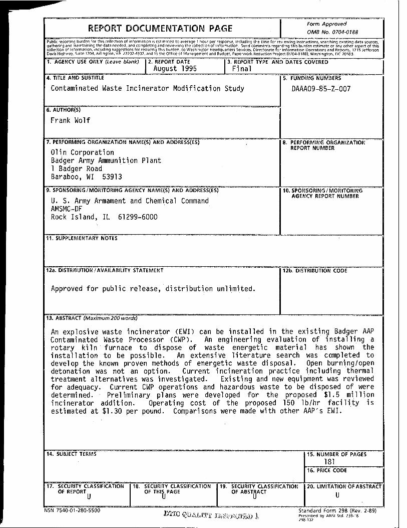
An explosive waste incinerator (EWI) can be installed in the existing Badger AAP Contaminated Waste Processor (CWP). An engineering evaluation of installing a rotary kiln furnace to dispose of waste energetic material has shown the installation to be possible. An extensive literature search was completed to develop the known proven methods of energetic waste disposal. Open burning/open detonation was not an option. Current incineration practice including thermal treatment alternatives was investigated. Existing and new equipment was reviewed for adequacy. Current CWP operations and hazardous waste to be disposed of were determined. Preliminary plans were developed for the proposed $1.5 million incinerator addition. Operating cost of the proposed 150 lb/hr facility is estimated at $1.30 per pound. Comparisons were made with other AAP's EWI.
14. SUBJECT TERMS 15. NUMBER OF PAGES
181 16. PRICE CODE
17. SECURITY CLASSIFICATION OF REPORT
18. SECURITY CLASSIFICATION OF THIS PAGE
19. SECURITY CLASSIFICATION OF ABSTRACT
20. LIMITATION OF ABSTRACT
U
NSN 7540-01-280-5500 EHG QüAMTf ffigl'ßüS) I
Standard Form 298 (Rev. 2-89) Prescribed by ANSI Std. Z39-18
GENERAL INSTRUCTIONS FOR COMPLETING SF 298
The Report Documentation Page (RDP) is used in announcing and cataloging reports. It is important that this information be consistent with the rest of the report, particularly the cover and title page. Instructions for filling in each block of the form follow. It is important to stay within the lines to meet optical scanning requirements.
Block 1. Agency Use Only (Leave blank).
Block 2. Report Date. Full publication date including day, month, and year, if available (e.g. 1 Jan 88). Must cite at least the year.
Blocks. Type of Report and Dates Covered. State whether report is interim, final, etc. If applicable, enter inclusive report dates (e.g. 10 Jun87-30Jun88).
Block 4. Title and Subtitle. A title is taken from the part of the report that provides the most meaningful and complete information. When a report is prepared in more than one volume, repeat the primary title, add volume number, and include subtitle for the specific volume. On classified documents enter the title classification in parentheses.
Block 5. Funding Numbers. To include contract and grant numbers; may include program element number(s), project number(s), task number(s), and work unit number(s). Use the following labels:
C G PE
Contract Grant Program Element
TA WU
Project Task Work Unit Accession No.
Block 6. Author(s). Name(s) of person(s) responsible for writing the report, performing the research, or credited with the content of the report. If editor or compiler, this should follow the name(s).
Block?. Performing Organization Name(s) and Address(es). Self-explanatory.
Block 8. Performing Organization Report Number. Enter the unique alphanumeric report number(s) assigned by the organization performing the report.
Block 9. Sponsoring/Monitoring Agency Name(s) and Address(es). Self-explanatory.
Block 10. Sponsoring/Monitoring Agency Report Number. (If known)
Block 11. Supplementary Notes. Enter information not included elsewhere such as: Prepared in cooperation with...; Trans, of...; To be published in.... When a report is revised, include a statement whether the new report supersedes or supplements the older report.
Block 12a. Distribution/Availability Statement. Denotes public availability or limitations. Cite any availability to the public. Enter additional limitations or special markings in all capitals (e.g. NOFORN, REL, ITAR).
DOD - See DoDD 5230.24, "Distribution Statements on Technical Documents."
DOE - See authorities. NASA- See Handbook NHB 2200.2. NTIS - Leave blank.
Block 12b. Distribution Code.
DOD - Leave blank. DOE - Enter DOE distribution categorie
NASA- NTIS -
from the Standard Distribution for Unclassified Scientific and Technical Reports. Leave blank. Leave blank.
Block 13. Abstract. Include a brief (Maximum 200 words) factual summary of the most significant information contained in the report.
Block 14. Subject Terms. Keywords or phrases identifying major subjects in the report.
Block 15. Number of Pages. Enter the total number of pages.
Block 16. Price Code. Enter appropriate price code (NTIS only).
Blocks 17.-19. Security Classifications. Self- explanatory. Enter U.S. Security Classification in accordance with U.S. Security Regulations (i.e., UNCLASSIFIED). If form contains classified information, stamp classification on the top and bottom of the page.
Block 20. Limitation of Abstract. This block must be completed to assign a limitation to the abstract. Enter either UL (unlimited) or SAR (same as report). An entry in this block is necessary if the abstract is to be limited. If blank, the abstract is assumed to be unlimited.
Standard Form 298 Back (Rev. 2-89) *U.S.GPO:1993-0-358-779
REPORT DOCUMENTATION PAGE Form Approved OMB NO. 0704-0188
PueJc ,»«».) Ocro.1. tor «. e'dl.«*». 0. "Icrm.lc" » ~.<r..i») » .-««I» I 1« f '"««». "a-J*? *» "~ r.^«rd ^«OTC*.^ «>»drr«.~"*«<.as»«:»<r.ol"torm.t». S«i< «»"«•"» "1«*^ "* *»"••**"*'• " U W.Uwvjor. HnMiarM« S*~«.i. Oi<«<Wrn« »> I"*""" Oo«»W<. -« »wm. 17« J.»->
^«.nm^IK to*««», o. "tor«.«».. "Ouo-1 H^^tion. tor Mol» I-. «worn. Su<i> 170. **».«" V» JI737-1M7. •« to »♦ C<*CT «I U.~»«»»l «no ft**»«.
1. AGENCY USE ONLY (Leava ö/an*; 2. REPORT DATE
August 1995
3. REPORT TYPE AND DATES COVERED
4. TITLE AND SUBTITLE
Contaminated Waste Incinerator Modification Study
5. FUNDING NUMBERS
S. AUTHORfS)
Frank Wolf
7. PERFORMING ORGANIZATION NAME(S) AND ADDRESS(ES)
01 in Corporation Badger Army Ammunition Plant Baraboo, WI 53913
8. PERFORMING ORGANIZATION REPORT NUMBER
SPONSORING/MONITORING AGENCY NAME(S) AND ADORlfSS{ES)
U. S. Army Armament and Chemical Command AMSMC-DF Rock Island, IL 61299-6000
10. SPONSORING/MONITORING AGENCY REPORT NUMBER
11. SUPPLEMENTARY NOTES
12a. DISTRIBUTION/AVAILABILITY STATEMENT
Approved for public release, distribution unlimited.
12b. DISTRIBUTION COOE
13. ABSTRACT (Maximum 200 words) . . Q^A~™ AAD An explosive waste incinerator (EWI) can be installed in the existing Badger AAP Contaminated Waste Processor (CWP). An engineering evaluation of installing a rotary kiln furnace to dispose of waste energetic material has shown the installation to be possible. An extensive literature search was completed to develop the known proven methods of energetic waste disposal. Open burning/open detonation was not an option. Current incineration practice including thermal treatment alternatives was investigated. Existing and new equipment was reviewed for adequacy. Current CWP operations and hazardous waste to be disposed of were determined. Preliminary plans were developed for the proposed $1.5 million incinerator addition. Operating cost of the proposed 150 lb/hr facility is estimated at $1.30 per pound. Comparisons were made with other AAP's EWI.
14. SUBJECT TERMS
Incinerator, explosive waste, energetic waste rotary kiln furnace
17. SECURITY CLASSIFICATION OF REPORT
NSN 7540-01-280-5500
18. SECURITY CLASSIFICATION OF THIS PAGE
19. SECURITY CLASSIFICATION OF ABSTRACT
u
15. NUMBER OF PAGES
15. PRICE CODE
20. LIMITATION OF ABSTRACT
Standard Form 298 (Rev. 2-39) Prescribed by ANSI Sid Z39-1 298-102
SF Form 298
SUMMARY
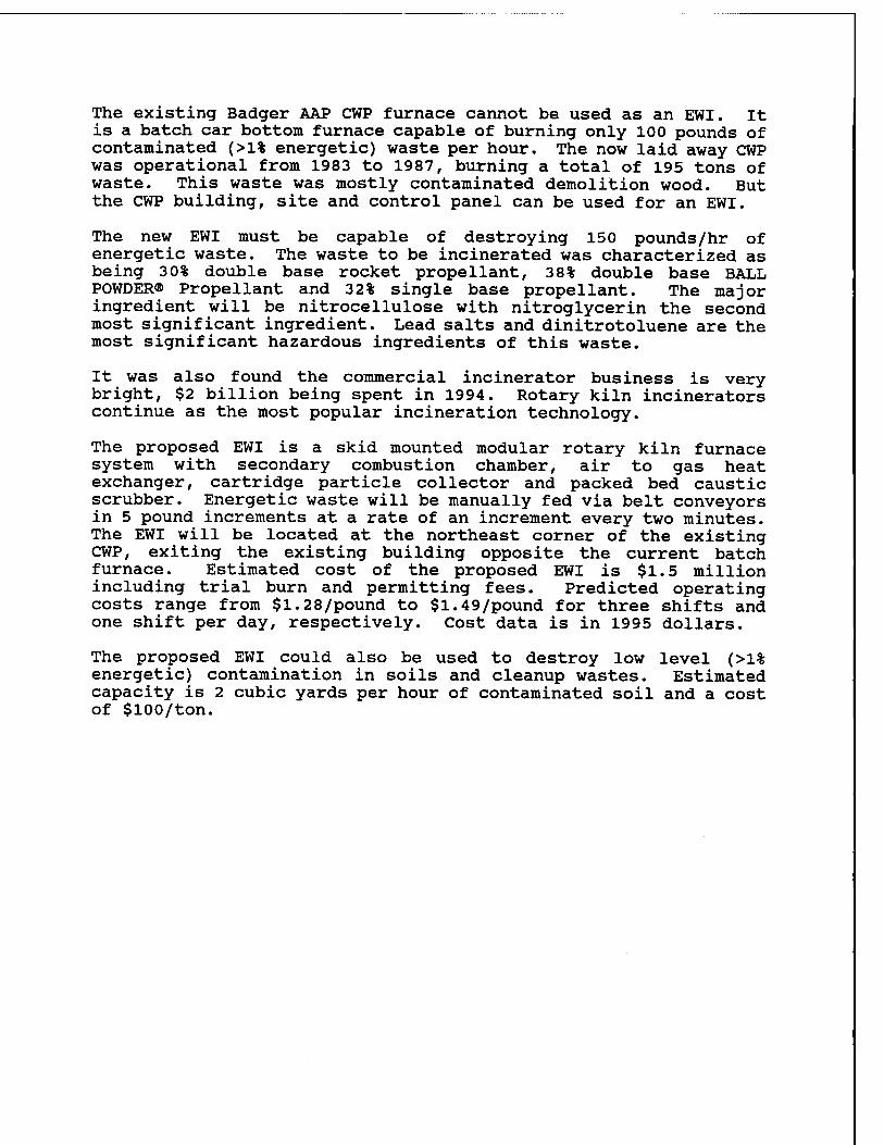
An explosive waste incinerator (EWI) can be installed in the existing Badger AAP contaminated waste processor (CWP). The objective of this engineering study was to evaluate the installation of a rotary kiln furnace in the CWP to dispose of waste energetic material. Results were positive. Badger does not currently have a method or facilities to dispose of energetic production waste material and an EWI is required. Open burning is not allowed.
A literature and document search was performed to find known proven methods to safely destroy concentrated energetic materials. The major survey method was to search the Knight Ridder Information, Inc. (DIALOG®) computer databased information system. Hundreds of citations were the result of the literature search. Ninety-seven citations are referenced in this report's bibliography. Research has been summarized in five categories - current practice, design, disposal alternatives, regulations and background information.
The literature search found many surveys, studies, papers and reports on the current practices of hazardous waste incineration. Incineration was the only developed disposal technology found other than open burning. Data reveal that well operated incinerators are capable of achieving 99.99 (the Resource Conservation Recovery Act (RCRA) performance standard) to greater than 99.999 percent destruction and removal efficiency (DRE). Also, it was found most hazardous waste incinerators are rotary kiln furnaces and with proper air pollution control, can meet the particle emission standards of 0.08 grains per dry standard cubic foot (gr/dscf).
State of the art incineration design was reviewed. Operating EWI burning waste similar to Badger AAP's are located at three AAPs - Radford, Lake City and Iowa. Each system is based on a rotary kiln furnace - Radford is a Bartlett Snow and the others a Tooele APE 1236 modified model. The three incinerators' equipment, control system and operations were reviewed and found to be very similar. Their propellant feed rates are: Radford 550 pounds/hr, Lake City 200 pounds/hr and Iowa 205 pounds/hr.
Hazardous waste combustion devices are permitted and regulated under RCRA and Wisconsin Administrative Code. Major performance standards are a minimum DRE of 99.99 percent for designated principal organic hazardous constituents, maximum particle emission of 0.08 gr/dscf and fugitive emissions must be controlled. Trial burns are an important aspect of the permitting process.
The existing Badger AAP CWP furnace cannot be used as an EWI. It is a batch car bottom furnace capable of burning only 100 pounds of contaminated (>1% energetic) waste per hour. The now laid away CWP was operational from 1983 to 1987, burning a total of 195 tons of waste. This waste was mostly contaminated demolition wood. But the CWP building, site and control panel can be used for an EWI.
The new EWI must be capable of destroying 150 pounds/hr of energetic waste. The waste to be incinerated was characterized as being 30% double base rocket propellant, 38% double base BALL POWDER® Propellant and 32% single base propellant. The major ingredient will be nitrocellulose with nitroglycerin the second most significant ingredient. Lead salts and dinitrotoluene are the most significant hazardous ingredients of this waste.
It was also found the commercial incinerator business is very bright, $2 billion being spent in 1994. Rotary kiln incinerators continue as the most popular incineration technology.
The proposed EWI is a skid mounted modular rotary kiln furnace system with secondary combustion chamber, air to gas heat exchanger, cartridge particle collector and packed bed caustic scrubber. Energetic waste will be manually fed via belt conveyors in 5 pound increments at a rate of an increment every two minutes. The EWI will be located at the northeast corner of the existing CWP, exiting the existing building opposite the current batch furnace. Estimated cost of the proposed EWI is $1.5 million including trial burn and permitting fees. Predicted operating costs range from $1.28/pound to $1.49/pound for three shifts and one shift per day, respectively. Cost data is in 1995 dollars.
The proposed EWI could also be used to destroy low level (>1% energetic) contamination in soils and cleanup wastes. Estimated capacity is 2 cubic yards per hour of contaminated soil and a cost of $100/ton.
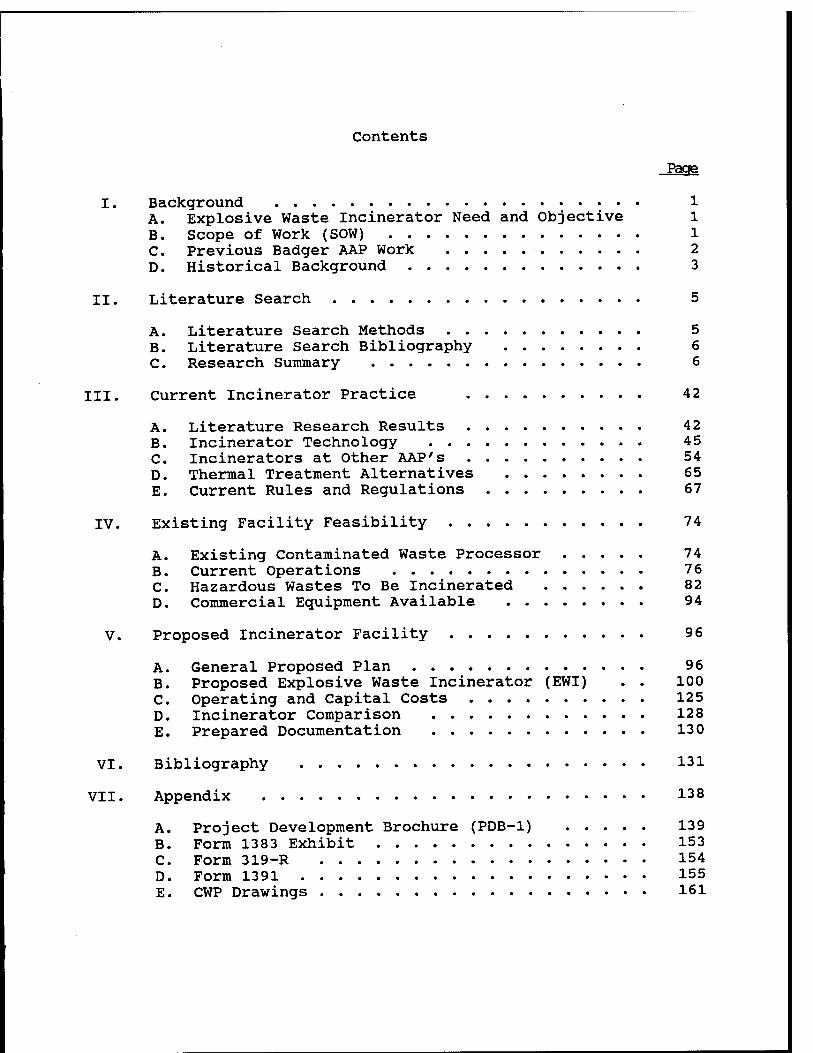
Contents
Page
I. Background 1 A. Explosive Waste Incinerator Need and Objective 1 B. Scope of Work (SOW) 1 C. Previous Badger AAP Work 2 D. Historical Background 3
II. Literature Search 5
A. Literature Search Methods 5 B. Literature Search Bibliography 6 C. Research Summary 6
III. Current Incinerator Practice . 42
A. Literature Research Results 42 B. Incinerator Technology 45 C. Incinerators at Other AAP's 54 D. Thermal Treatment Alternatives 65 E. Current Rules and Regulations 67
IV. Existing Facility Feasibility 74
A. Existing Contaminated Waste Processor 74 B. Current Operations 76 C. Hazardous Wastes To Be Incinerated 82 D. Commercial Eguipment Available 94
V. Proposed Incinerator Facility 96
A. General Proposed Plan 96 B. Proposed Explosive Waste Incinerator (EWI) . . 100 C. Operating and Capital Costs 125 D. Incinerator Comparison 128 E. Prepared Documentation 130
VI. Bibliography 131
VII. Appendix 138
A. Project Development Brochure (PDB-1) 139 B. Form 1383 Exhibit 153 C. Form 319-R 154 D. Form 1391 155 E. CWP Drawings 161
I. BACKGROUND
A. Explosive Waste Incinerator Need and Objective
Badger Army Ammunition Plant (AAP) requires an explosive waste incinerator to fulfill its Mobilization mission to produce various military propellants according to a specific schedule. The large quantities of production will generate significant amounts of explosive waste to be disposed of. Badger does not currently have a method or facilities to treat or dispose of these explosive wastes. Open burning is not allowed.
The overall objective of the project is to evaluate the use of Badger's existing Contaminated Waste Processor (CWP) to also dispose of waste energetic compounds through the addition of a rotary kiln furnace. Badger's existing CWP is designed to burn materials contaminated with less than 1% energetic compounds. By adding a burner unit that is less susceptible to rapid gas expansion damage, the explosive wastes from production could be treated on-site.
B. Scope of Work (SOW)
The final product of the project is this engineering report detailing the preliminary design for modification of the existing CWP into a dual use facility to burn contaminated material and also burn concentrated waste energetic materials.
The project study SOW includes the following tasks:
Task 1: Perform a document search on known proven methods to safely burn concentrated energetic materials in confined space and within current emission requirements.
Task 2: Review existing equipment and new available commercial equipment for adequacy to meet the process parameters specifically for those types of energetic material generated at Badger.
Task 3: Develop preliminary plans, specifications, and cost estimates to convert the existing CWP into a dual use facility. Prepare a PDB-1, a 1391, and IPM 319-R funding document forms for final project development.
Task 4: Document the study in a final technical report.
C. Previous Badger AAP Work
Initial consideration of an explosive waste incinerator was in 1975 when certain regulations of the Clean Air Act of 1970, as amended, revoked the regulation providing for open burning of explosives. A Military Construction - Army (MCA) project was initiated then for construction in fiscal year 1979. The project then was to ... "construct a 7 ton per day incineration facility capable of destroying waste propellant and explosives (Classes 2, 2A and 7). Design of the incinerator shall be based on the deactivation furnace (APE 1236) used at Tooele Army Depot ..." l as per specific military direction. Cost was estimated at $300,000.
The explosive waste incinerator project (T00400) has been resubmitted into the MCA program in subseguent fiscal years. By 1989, the project scheduled for fiscal 1996 had a new number, 004478, and the cost had escalated to $1,150,000. Currently, the project is considered a long range deferred project scheduled for fiscal year 2010 funding. It is listed in Badger AAP's 1383 reports as project BAAP M0008 at a funding reguirement of one million dollars.
Also, conceived in 1975 was the Contaminated Waste Incinerator/ Processor (CWP). This incinerator or processor was funded under the 1981 MCA program. Construction by the Corps of Engineers was accomplished from June 1981 to August 1983. The CWP was operational 29 August 1983. Actual incineration was almost exclusively explosive-contaminated wood of which 195 tons were burned from 1983 to 1987. It was subsequently laid away and mothballed in 1992 when destruction of contaminated waste was no longer reguired.
Both the EWI and CWP were first safety sited in 1976 and the siting was revised 28 July 1978.2 The CWP was built as sited.
1 DD Form 1391 (12 Oct 1976)
2 Department of the Army letter (SARBA-SE, 29 Dec 1976)
D. Historical Background
Incineration as we know it today began slightly over 100 years ago when the first municipal waste "destructor" was installed in Nottingham, England. Incineration use in the United States grew rapidly, from the first installation on Governor's Island in New York to more than 200 units in 1921. Until the 1950s, incinerators and their attendant smoke and odors were accepted as a necessary evil and their operations were generally under- taken in the cheapest possible manner. However, as billowing smoke stacks became less of a symbol of prosperity and air pollution regulations began to emerge, incineration systems improved dramatically. These improvements included continuous feed, improved combustion control, and the application of air pollution control systems.
Incineration has been employed for the disposal of industrial chemical wastes (hazardous waste) for over 50 years. Initial units borrowed from municipal waste technology, but poor performance and adaptability of these early grate-type units led to the subsequent use of rotary kilns. Many of the earliest rotary kiln facilities were in West Germany. The first rotary kiln unit for industrial wastes in the United States was installed in 1948 at the Dow Chemical Company facility in Midland, Michigan.3
The first U. S. Federal standards for the control of incineration emissions were applied to municipal waste combustors under the New Source Performance Standards (NSPS) provisions of the Clean Air Act (CAA) of 1970. The NSPS established a time-averaged particulate emission limit of 180 milligrams per dry standard cubic meter for all incineration units constructed after August 1971 having charging rates greater than 50 tons per day. On February 11, 1991, the U. S. Environmental Protection Agency (EPA) promulgated more stringent rules for all existing and new municipal waste combustors (MWCs) with unit capacities greater than 225 metric tons per day. This action required the use of good combustion practice at all facilities, set lower particulate emissions limits to control metals and established emission limits on nitrogen oxides (N0X), organics, hydrogen chloride (HC1), sulfur dioxide (S02) and opacity.
4
3 Sercu (1959)
4 EPA (February 11, 1991)
The February 1991 MWC rules are to be modified to comply with the provisions of the November 1990 CAA Amendments. These revisions will include rules for facilities with capacities less than 225 metric tons per day, emission limits for cadmium, lead and mercury, and requirements for the use of the maximum achievable control technology.
Hazardous waste incineration performance standards were not promulgated until after the passage of the Resource Conservation and Recovery Act (RCRA). Technical standards for incinerators were proposed in December 1978, under Section 3004 of RCRA. These standards provided both performance and operating requirements. The performance standards included requirements for acceptable levels of combustion efficiency, destruction efficiency for organic compounds, HC1 removal efficiency and an emission limit for particulate matter. Operational standards required semicontinuous monitoring of process variables, such as carbon monoxide (CO), and specific minimum temperature and combustion gas residence time levels. Rules were promulgated in 1980 to 1982.5
The Federal Facility Compliance Act (FFCA) amending RCRA was signed by President Bush on October, 1992. The most significant provision of the FFCA was the waiver of sovereign immunity. This waiver subjects Federal facilities to the same "incentives" as the private sector for compliance. The munitions Provision contained in Section 107 of the FFCA, modifies Section 3004 of RCRA by adding a new subsection (y) on Munitions. Section 107 requires the EPA to develop, after consultation with the Department of Defense (DOD) and appropriate State officials, regulations identifying when military munitions (including conventional and chemical munitions) become hazardous waste, and to provide for the safe transportation and storage of such waste. The FFCA requires EPA to promulgate the final "Munitions Rule" by October 6, 1994.6 This date was not met.
This historical background is continued and brought up to date in the following various report sections.
5 EPA (24 June 1982)
6 Todd A. Kimmell, et al (March 1994)
II. LITERATURE SEARCH
Literature Search Methods
A literature and document search was performed to find known proven methods to safely burn or destroy concentrated energetic materials. The major survey method was to search the Knight- Ridder Information, Inc. (DIALOG®) computer databased information system. Three major databases were accessed through this system. These databases were searched using the following key words: incinerator, hazardous waste, energetic material, design, explosives, propellants, waste disposal and demilitarization.
Most information was found in DIALOG®'s National Technical Information System (NTIS) database. NTIS is produced by the U. S. Department of Commerce and consists of summaries of U. S. government-sponsored research, development, and engineering, plus analysis prepared by federal agencies, their contractors or grantees. It is the means through which unclassified publicly available reports are procured from agencies such as National Aeronautics and Space Administration (NASA), Department of Defense (DOD), Department of Energy (DOE), Department of Transportation (DOT), and some 240 other agencies.
Another database from DIALOG® used was SCISEARCH®. This is an international, multidisciplinary index to the literature science, technology, biomedicine and related disciplines produced by the Institute for Scientific Information of Philadelphia, Pennsylvania. It indexes all significant items (articles, review papers, meeting abstracts, editorials, book reviews, etc) from approximately 4,500 major scientific and technical journals.
The third major database accessed by DIALOG® was ENVIRONMENTAL BIBLIOGRAPHY which provides access to the contents of more than 400 of the world's journals covering the environment.
Although DIALOG® was the major search source, the other sources searched were the University of Wisconsin-Madison, Wendt Library Technical Reports Center, the Army Ammunition Plants and our own Badger AAP files. Ammunitions plants contacted were Iowa AAP, Lake City AAP and Radford AAP.
Another literature search source was a NTIS Published Search® entitled "Remediation of Explosive Materials (Sep 85-Present)". The bibliography contained 170 citations concerning the reclamation of sites polluted with munitions wastes. Articles discuss the remediation and degradation of such materials as TNT, propellants, explosives and other energetic materials.7
B. Literature Search Bibliography
The literature search resulted in hundreds of citations on energetic material disposal or related topics. Ninety-eight citations are referenced in this report's bibliography. Bibliography is found at paragraph VI.
C. Research Summary
The literature research has been summarized in five categories - practice, design, alternatives, regulations and background information. Category summaries are presented in the following paragraphs. A table of literature citations has been compiled for each category including a short description of the citation.
1. Hazardous Waste Incinerator Practice
Current incinerator practice is briefly summarized in this paragraph and more fully developed in paragraph and the results discussed in paragraph III A. Specific literature citations may be found in Table II -1. Hazardous Waste Incinerator Practice, Literature Citations.
Current practice was reviewed in four documents. A. Trenholm et al, with the Midwest Research Institute reported an early 1984 survey of eight hazardous waste incinerators for the EPA. They found Destruction and Removal Efficiencies (DRE) even then were generally above 99.99%.8 The EPA conducted five regional seminars during 1992 on hazardous waste incinerator operating parameters and published its regional experience and problems.9 Clyde Dempsey and Timothy Oppelt, project officers of the EPA's Risk Reduction Engineering Laboratory, prepared an extensive review on the current state of knowledge for the January 1993 issue of the Journal of Air & Waste
7
S
9
NTIS (November 1994)
A. Trenholm (May 1984)
Justice Manning (October 1993)
6
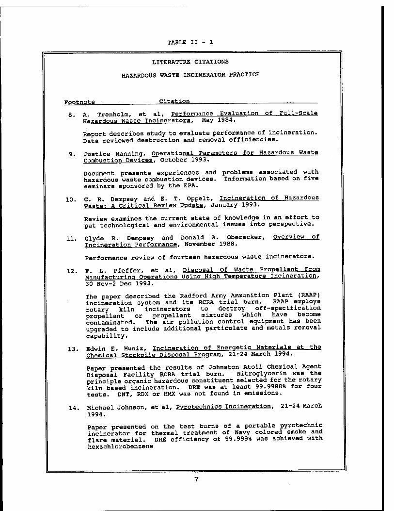
TABLE II - 1
LITERATURE CITATIONS
HAZARDOUS WASTE INCINERATOR PRACTICE
Footnote Citation
8. A. Trenholm, et al, Performance Evaluation of Full-Scale Hazardous Waste Incinerators, May 1984.
Report describes study to evaluate performance of incineration. Data reviewed destruction and removal efficiencies.
9. Justice Manning, Operational Parameters for Hazardous Waste Combustion Devices, October 1993.
Document presents experiences and problems associated with hazardous waste combustion devices. Information based on five seminars sponsored by the EPA.
10. C. R. Dempsey and E. T. Oppelt, Incineration of Hazardous Waste; A Critical Review Update, January 1993.
Review examines the current state of knowledge in an effort to put technological and environmental issues into perspective.
11. Clyde R. Dempsey and Donald A. Oberacker, Overview of Incineration Performance, November 1988.
Performance review of fourteen hazardous waste incinerators.
12. F. L. Pfeffer, et al, Disposal Of Waste Propellant From Manufacturing Operations Using Hiah Temperature Incineration. 30 Nov-2 Dec 1993.
The paper described the Radford Army Ammunition Plant (RAAP) incineration system and its RCRA trial burn. RAAP employs rotary kiln incinerators to destroy off-specification propellant or propellant mixtures which have become contaminated. The air pollution control equipment has been upgraded to include additional particulate and metals removal capability.
13. Edwin E. Muniz, Incineration of Energetic Materials at the Chemical Stockpile Disposal Program, 21-24 March 1994.
Paper presented the results of Johnston Atoll Chemical Agent Disposal Facility RCRA trial burn. Nitroglycerin was the principle organic hazardous constituent selected for the rotary kiln based incineration. DRE was at least 99.9988% for four tests. DNT, RDX or HMX was not found in emissions.
14. Michael Johnson, et al, Pyrotechnics Incineration, 21-24 March 1994.
Paper presented on the test burns of a portable pyrotechnic incinerator for thermal treatment of Navy colored smoke and flare material. DRE efficiency of 99.999% was achieved with hexachlorobenzene
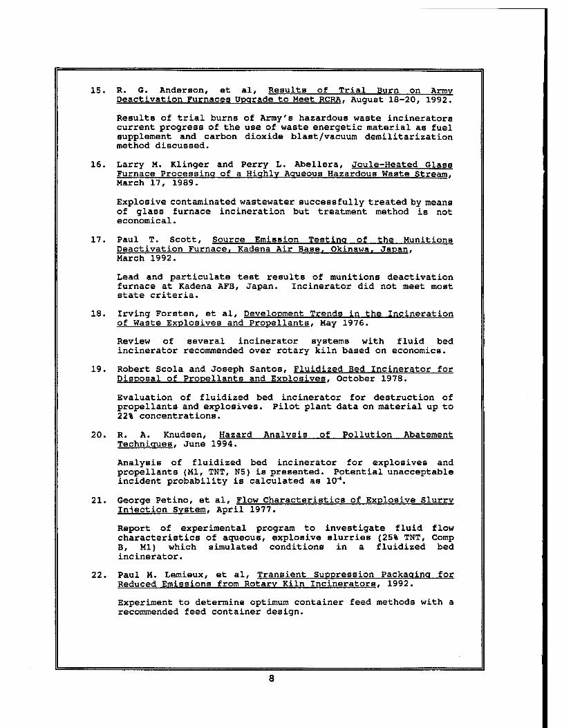
15. R. 6. Anderson, et al, Results of Trial Burn on Army Deactlvation Furnaces Upgrade to Meet RCRA. August 18-20, 1992.
Results of trial burns of Army's hazardous waste incinerators current progress of the use of waste energetic material as fuel supplement and carbon dioxide blast/vacuum demilitarization method discussed.
16. Larry M. Klinger and Perry L. Abellera, Joule-Heated Glass Furnace Processing of a Highly Aqueous Hazardous Waste Stream. March 17, 1989.
Explosive contaminated wastewater successfully treated by means of glass furnace incineration but treatment method is not economical.
17. Paul T. Scott, Source Emission Testing of the Munitions Deactivation Furnace, Kadena Air Base, Okinawa. Japan. March 1992.
Lead and particulate test results of munitions deactivation furnace at Kadena AFB, Japan. Incinerator did not meet most state criteria.
18. Irving Forsten, et al, Development Trends in the Incineration of Waste Explosives and Propellants, May 1976.
Review of several incinerator systems with fluid bed incinerator recommended over rotary kiln based on economics.
19. Robert Scola and Joseph Santos, Fluidized Bed Incinerator for Disposal of Propellants and Explosives. October 1978.
Evaluation of fluidized bed incinerator for destruction of propellants and explosives. Pilot plant data on material up to 22% concentrations.
20. R. A. Knudsen, Hazard Analysis of Pollution Abatement Technigues. June 1994.
Analysis of fluidized bed incinerator for explosives and propellants (Ml, TNT, N5) is presented. Potential unacceptable incident probability is calculated as 10"4.
21. George Petino, et al, Flow Characteristics of Explosive Slurry Injection System. April 1977.
Report of experimental program to investigate fluid flow characteristics of aqueous, explosive slurries (25% TNT, Comp B, Ml) which simulated conditions in a fluidized bed incinerator.
22. Paul M. Lemieux, et al, Transient Suppression Packaging for Reduced Emissions from Rotary Kiln Incinerators, 1992.
Experiment to determine optimum container feed methods with a recommended feed container design.
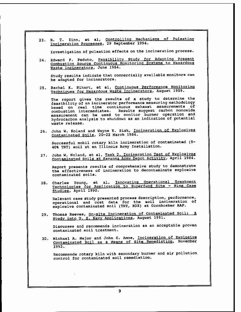
23. B. T. Zinn, et al, Controlling Mechanisms of Pulsating Incineration Processes. 29 September 1994.
Investigation of pulsation effects on the incineration process.
24. Edward F. Peduto, Feasibility Study for Adapting Present Combustion Source Continuous Monitoring Systems to Hazardous Waste Incinerators, June 1984.
Study results indicate that commercially available monitors can be adapted for incinerators.
25. Rachel K. Nihart, et al, Continuous Performance Monitoring Technicrues for Hazardous Waste Incinerators, August 1989.
The report gives the results of a study to determine the feasibility of an incinerator performance measuring methodology based on real time continuous exhaust measurements of combustion intermediates. Results suggest carbon monoxide measurement can be used to monitor burner operation and hydrocarbon analysis to shutdown as an indication of potential waste release.
26. John W. Noland and Wayne E. Sisk, Incineration of Explosives Contaminated Soils, 20-22 March 1984.
Successful mobil rotary kiln incineration of contaminated (9- 40% TNT) soil at an Illinois Army Installation.
27. John W. Noland, et al, Task 2. Incineration Test of Explosives Contaminated Soils at Savanna Armv Depot Activity, April 1984.
Report presents results of comprehensive study to demonstrate the effectiveness of incineration to decontaminate explosive contaminated soils.
28. Charles Young, et al, Innovative Operational Treatment Technologies for Application to Superfund Site - Nine Case Studies. April 1990.
Relevant case study presented process description, performance, operational and cost data for the soil incineration of explosive contaminated soil (TNT, RDX) at Cornhusker AAP.
29. Thomas Reeves, On-site Incineration of Contaminated Soil: A Study into ü. S. Naw Applications, August 1991.
Discusses and recommends incineration as an acceptable proven contaminated soil treatment.
30. Michael A. Major and John C. Amos, Incineration of Explosive Contaminated Soil as a Means of Site Remediation, November 1992.
Recommends rotary kiln with secondary burner and air pollution control for contaminated soil remediation.
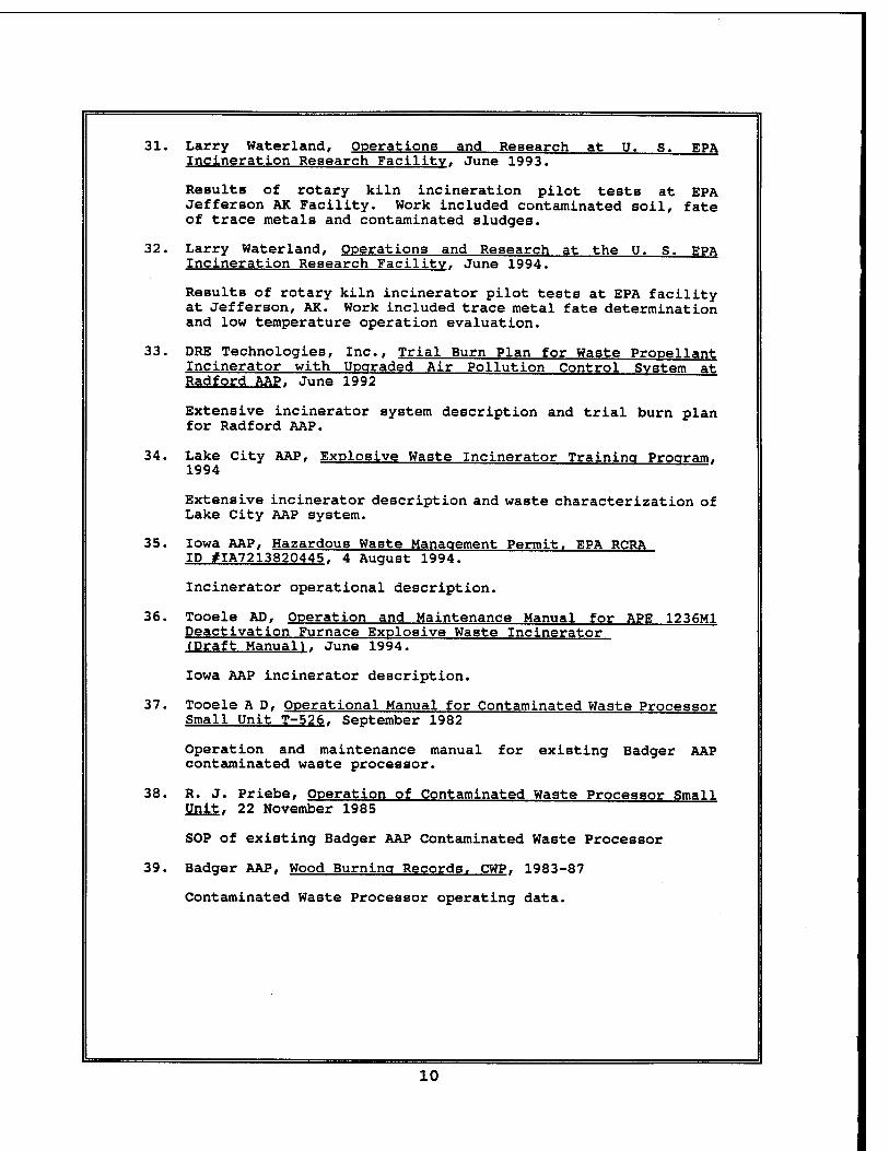
31. Larry Waterland, Operations and Research at U. s. EPA Incineration Research Facility. June 1993.
Results of rotary kiln incineration pilot tests at EPA Jefferson AK Facility. Work included contaminated soil, fate of trace metals and contaminated sludges.
32. Larry Waterland, Operations and Research at the U. S. EPA Incineration Research Facility. June 1994.
Results of rotary kiln incinerator pilot tests at EPA facility at Jefferson, AK. Work included trace metal fate determination and low temperature operation evaluation.
33. DRE Technologies, Inc., Trial Burn Plan for Waste Propellant Incinerator with Upgraded Air Pollution Control System at Radford AAP. June 1992
Extensive incinerator system description and trial burn plan for Radford AAP.
34. Lake City AAP, Explosive Waste Incinerator Training Program. 1994
Extensive incinerator description and waste characterization of Lake City AAP system.
35. Iowa AAP, Hazardous Waste Management Permit. EPA RCRA ID #IA7213820445. 4 August 1994.
Incinerator operational description.
36. Tooele AD, Operation and Maintenance Manual for APE 1236M1 Deactivation Furnace Explosive Waste Incinerator (Draft Manual). June 1994.
Iowa AAP incinerator description.
37. Tooele A D, Operational Manual for Contaminated Waste Processor Small Unit T-526. September 1982
Operation and maintenance manual for existing Badger AAP contaminated waste processor.
38. R. J. Priebe, Operation of Contaminated Waste Processor Small Unit. 22 November 1985
SOP of existing Badger AAP Contaminated Waste Processor
39. Badger AAP, Wood Burning Records. CWP. 1983-87
Contaminated Waste Processor operating data.
10
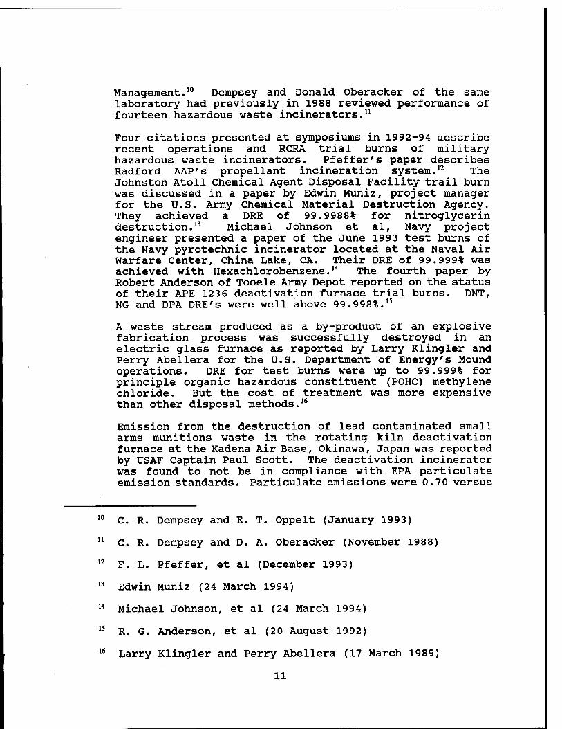
Management.10 Dempsey and Donald Oberacker of the same laboratory had previously in 1988 reviewed performance of fourteen hazardous waste incinerators.11
Four citations presented at symposiums in 1992-94 describe recent operations and RCRA trial burns of military hazardous waste incinerators. Pfeffer's paper describes Radford AAP's propellant incineration system.12 The Johnston Atoll Chemical Agent Disposal Facility trail burn was discussed in a paper by Edwin Muniz, project manager for the U.S. Army Chemical Material Destruction Agency. They achieved a DRE of 99.9988% for nitroglycerin destruction.13 Michael Johnson et al, Navy project engineer presented a paper of the June 1993 test burns of the Navy pyrotechnic incinerator located at the Naval Air Warfare Center, China Lake, CA. Their DRE of 99.999% was achieved with Hexachlorobenzene.14 The fourth paper by Robert Anderson of Tooele Army Depot reported on the status of their APE 1236 deactivation furnace trial burns. DNT, NG and DPA DRE's were well above 99.998%.15
A waste stream produced as a by-product of an explosive fabrication process was successfully destroyed in an electric glass furnace as reported by Larry Klingler and Perry Abellera for the U.S. Department of Energy's Mound operations. DRE for test burns were up to 99.999% for principle organic hazardous constituent (POHC) methylene chloride. But the cost of treatment was more expensive than other disposal methods.16
Emission from the destruction of lead contaminated small arms munitions waste in the rotating kiln deactivation furnace at the Kadena Air Base, Okinawa, Japan was reported by USAF Captain Paul Scott. The deactivation incinerator was found to not be in compliance with EPA particulate emission standards. Particulate emissions were 0.70 versus
10
li
12
13
14
15
16
C. R. Dempsey and E. T. Oppelt (January 1993)
C. R. Dempsey and D. A. Oberacker (November 1988)
F. L. Pfeffer, et al (December 1993)
Edwin Muniz (24 March 1994)
Michael Johnson, et al (24 March 1994)
R. G. Anderson, et al (20 August 1992)
Larry Klingler and Perry Abellera (17 March 1989)
11
23
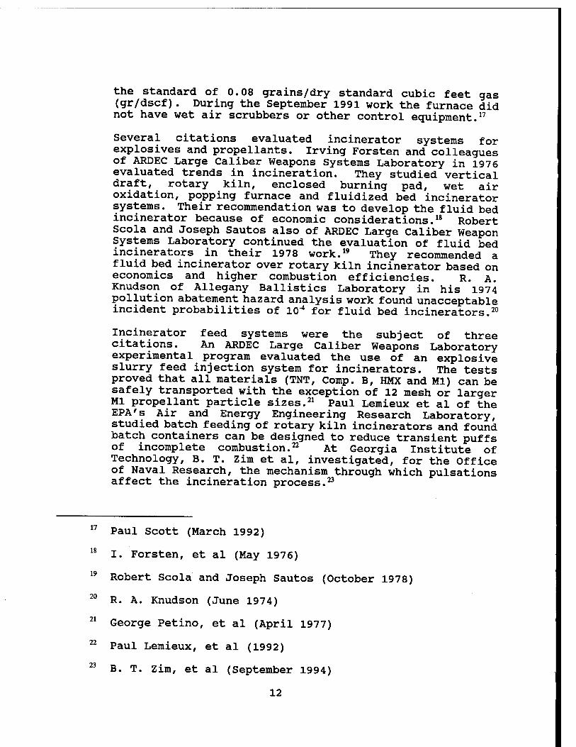
the standard of 0.08 grains/dry standard cubic feet gas (gr/dscf). During the September 1991 work the furnace did not have wet air scrubbers or other control equipment.17
Several citations evaluated incinerator systems for explosives and propellants. Irving Forsten and colleagues of ARDEC Large Caliber Weapons Systems Laboratory in 1976 evaluated trends in incineration. They studied vertical draft, rotary kiln, enclosed burning pad, wet air oxidation, popping furnace and fluidized bed incinerator systems. Their recommendation was to develop the fluid bed incinerator because of economic considerations.18 Robert Scola and Joseph Sautos also of ARDEC Large Caliber Weapon Systems Laboratory continued the evaluation of fluid bed incinerators in their 1978 work.19 They recommended a fluid bed incinerator over rotary kiln incinerator based on economics and higher combustion efficiencies. R. A. Knudson of Allegany Ballistics Laboratory in his 1974 pollution abatement hazard analysis work found unacceptable incident probabilities of 10"* for fluid bed incinerators.20
Incinerator feed systems were the subject of three citations. An ARDEC Large Caliber Weapons Laboratory experimental program evaluated the use of an explosive slurry feed injection system for incinerators. The tests proved that all materials (TNT, Comp. B, HMX and Ml) can be safely transported with the exception of 12 mesh or larger Ml propellant particle sizes.21 Paul Lemieux et al of the EPA's Air and Energy Engineering Research Laboratory, studied batch feeding of rotary kiln incinerators and found batch containers can be designed to reduce transient puffs of incomplete combustion.22 At Georgia Institute of Technology, B. T. Zim et al, investigated, for the Office of Naval Research, the mechanism through which pulsations affect the incineration process.23
17 Paul Scott (March 1992)
18 I. Forsten, et al (May 1976)
19 Robert Scola and Joseph Sautos (October 1978)
20 R. A. Knudson (June 1974)
21 George Petino, et al (April 1977)
22 Paul Lemieux, et al (1992)
B. T. Zim, et al (September 1994)
12
24
25
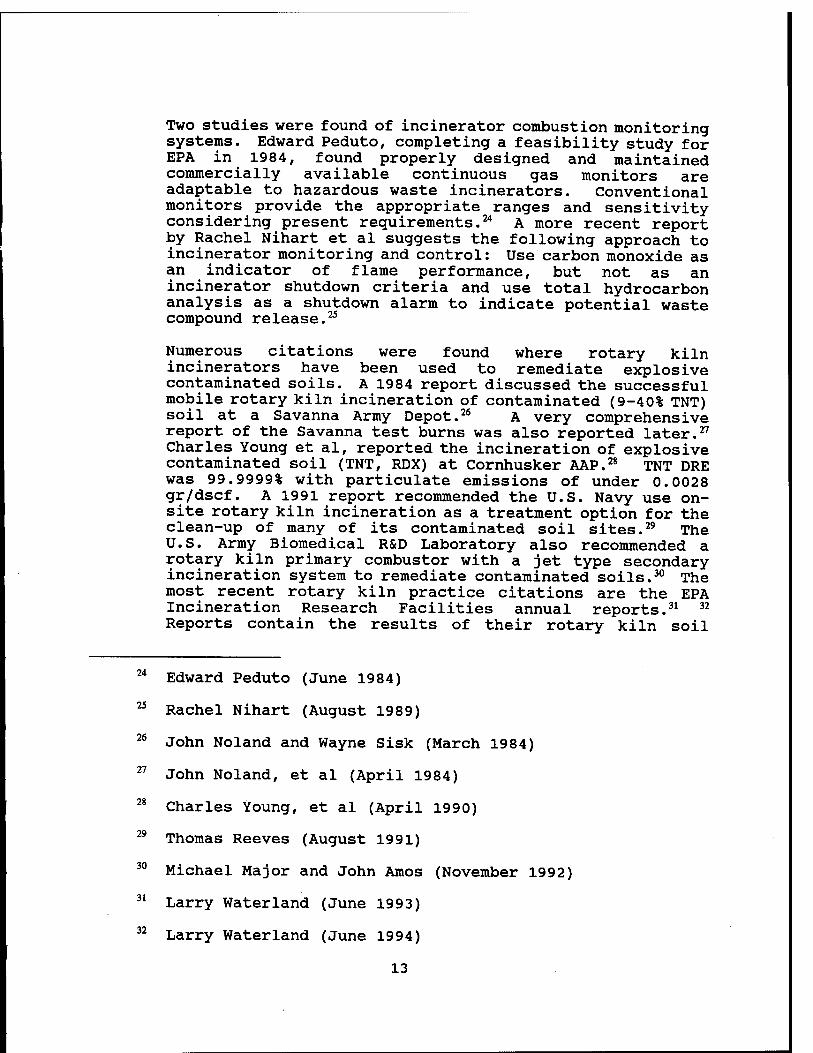
Two studies were found of incinerator combustion monitoring systems. Edward Peduto, completing a feasibility study for EPA in 1984, found properly designed and maintained commercially available continuous gas monitors are adaptable to hazardous waste incinerators. Conventional monitors provide the appropriate ranges and sensitivity considering present requirements.24 A more recent report by Rachel Nihart et al suggests the following approach to incinerator monitoring and control: Use carbon monoxide as an indicator of flame performance, but not as an incinerator shutdown criteria and use total hydrocarbon analysis as a shutdown alarm to indicate potential waste compound release.25
Numerous citations were found where rotary kiln incinerators have been used to remediate explosive contaminated soils. A 1984 report discussed the successful mobile rotary kiln incineration of contaminated (9-40% TNT) soil at a Savanna Army Depot.26 A very comprehensive report of the Savanna test burns was also reported later.27
Charles Young et al, reported the incineration of explosive contaminated soil (TNT, RDX) at Cornhusker AAP.28 TNT DRE was 99.9999% with particulate emissions of under 0.0028 gr/dscf. A 1991 report recommended the U.S. Navy use on- site rotary kiln incineration as a treatment option for the clean-up of many of its contaminated soil sites.29 The U.S. Army Biomedical R&D Laboratory also recommended a rotary kiln primary combustor with a jet type secondary incineration system to remediate contaminated soils.30 The most recent rotary kiln practice citations are the EPA Incineration Research Facilities annual reports.31 32
Reports contain the results of their rotary kiln soil
Edward Peduto (June 1984)
Rachel Nihart (August 1989)
26 John Noland and Wayne Sisk (March 1984)
27 John Noland, et al (April 1984)
Charles Young, et al (April 1990)
Thomas Reeves (August 1991)
Michael Major and John Amos (November 1992)
Larry Waterland (June 1993)
Larry Waterland (June 1994)
13
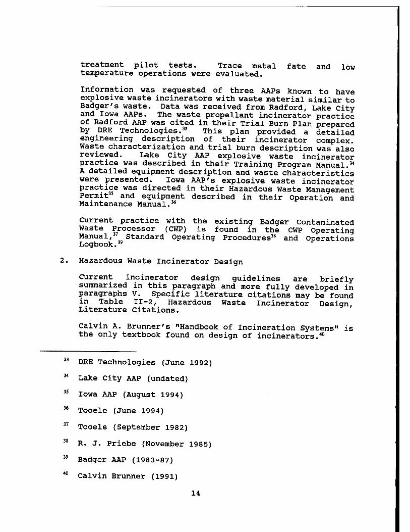
treatment pilot tests. Trace metal fate and low temperature operations were evaluated.
Information was requested of three AAPs known to have explosive waste incinerators with waste material similar to Badger's waste. Data was received from Radford, Lake city and Iowa AAPs. The waste propellant incinerator practice of Radford AAP was cited in their Trial Burn Plan prepared by DRE Technologies.33 This plan provided a detailed engineering description of their incinerator complex. Waste characterization and trial burn description was also reviewed. Lake city AAP explosive waste incinerator practice was described in their Training Program Manual.34
A detailed equipment description and waste characteristics were presented. Iowa AAP's explosive waste incinerator practice was directed in their Hazardous Waste Management Permit35 and equipment described in their Operation and Maintenance Manual.36
Current practice with the existing Badger Contaminated Waste Processor (CWP) is found in the CWP Operating Manual,37 Standard Operating Procedures38 and Operations Logbook.39
2. Hazardous Waste Incinerator Design
Current incinerator design guidelines are briefly summarized in this paragraph and more fully developed in paragraphs V. Specific literature citations may be found in Table II-2, Hazardous Waste Incinerator Design, Literature Citations.
Calvin A. Brunner's "Handbook of Incineration Systems" is the only textbook found on design of incinerators.40
DRE Technologies (June 1992)
Lake City AAP (undated)
Iowa AAP (August 1994)
Tooele (June 1994)
Tooele (September 1982)
R. J. Priebe (November 1985)
Badger AAP (1983-87)
40 Calvin Brunner (1991)
14
35
36
37
38
39
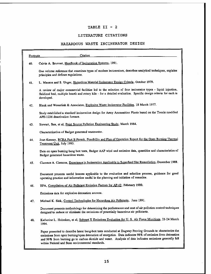
TABLE II - 2
LITERATURE CITATIONS
HAZARDOUS WASTE INCINERATOR DESIGN
Footnote Citation
40. Calvin A. Brunner, Handbook of Incineration Systems. 1991.
One volume reference that examines types of modern incinerators, describes analytical techniques, explains principles and defines regulations.
41. L. Manson and S. Unger, Hazardous Material Incinerator Design Criteria. October 1979.
A review of major commercial facilities led to the selection of four incinerator types - liquid injection, fluidized bed, multiple hearth and rotary kiln - for a detailed evaluation. Specific design criteria for each is developed.
42. Blank and Wesselink & Associates, Explosive Waste Incinerator Facilities. 18 March 1977.
Study established a standard incineration design for Army Ammunition Plants based on the Tooele modified APE-1236 deactivation furnace.
43. Stewart, Ben, et al, Point Source Pollution Engineering Study. March 1984.
Characterization of Badger generated wastewater.
44. Joan Kenney, RCRA Part B Permit. Feasibility and Plan of Operation Report for the Open Burning Thermal Treatment Unit. July 1993.
Data on open burning bang box tests, Badger AAP wind and emission data, quantities and characteristics of Badger generated hazardous waste.
45. Clarence A. demons, Experience in Incineration Applicable to Superfund Site Remediation. December 1988.
Document presents useful lessons applicable to the evaluation and selection process, guidance for good operating practice and information useful in the planning and initiation of remedies.
46. EPA, Compilation of Air Pollutant Emission Factors for AP-42. February 1980.
Emissions data for explosive detonation sources.
47. Michael K. Sink. Control Technologies for Hazardous Air Pollutants. June 1991.
Document presents methodology for determining the performance and cost of air pollution control techniques designed to reduce or eliminate the emissions of potentially hazardous air pollutants.
48. Katherine L. Heineken, et al, Subpart X Emissions Evaluation for U. S. Air Force Munitions. 21-24 March 1994.
Paper presented to describe latest bang-box teste conducted at Dugway Proving Grounds to characterize the emissions from open burning/open detonation of energetics. Data indicates 98% of emission from detonation and 99% from burning go to carbon dioxide and water. Analysis of data indicates emissions generally fall within Federal and State environmental standards.
15
41
42
43
44
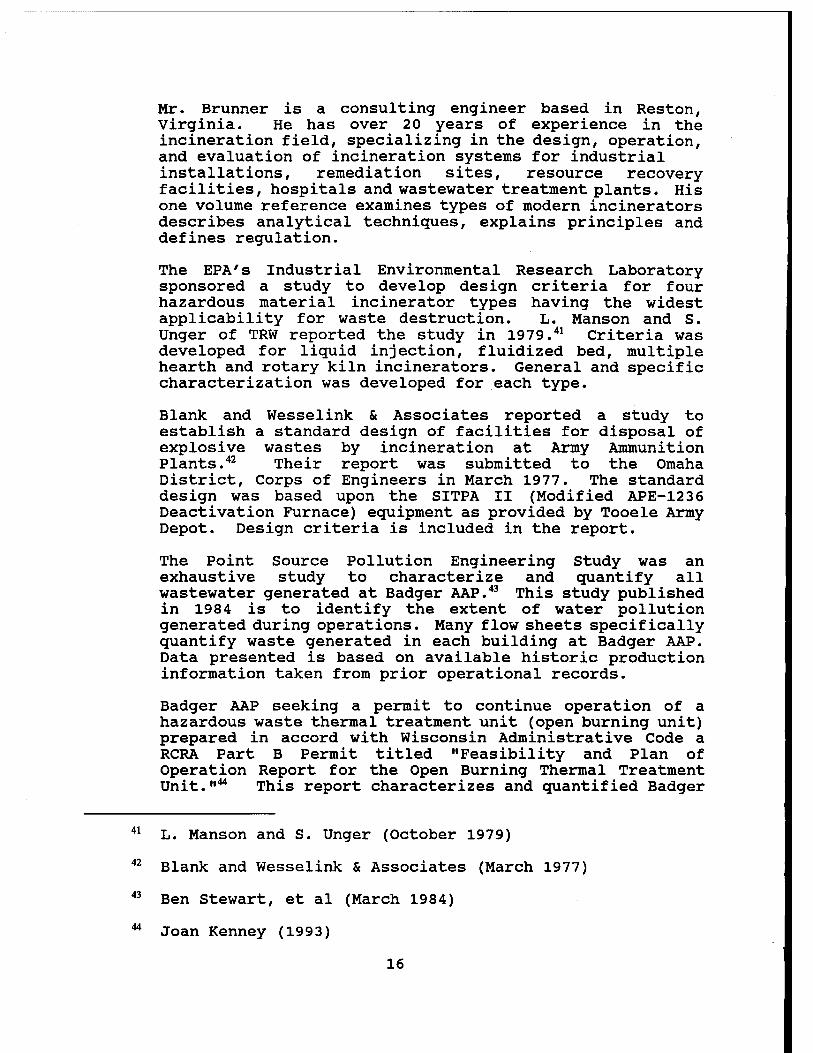
Mr. Brunner is a consulting engineer based in Reston, Virginia. He has over 20 years of experience in the incineration field, specializing in the design, operation, and evaluation of incineration systems for industrial installations, remediation sites, resource recovery facilities, hospitals and wastewater treatment plants. His one volume reference examines types of modern incinerators describes analytical techniques, explains principles and defines regulation.
The EPA's Industrial Environmental Research Laboratory sponsored a study to develop design criteria for four hazardous material incinerator types having the widest applicability for waste destruction. L. Manson and S. Unger of TRW reported the study in 1979.41 Criteria was developed for liquid injection, fluidized bed, multiple hearth and rotary kiln incinerators. General and specific characterization was developed for each type.
Blank and Wesselink & Associates reported a study to establish a standard design of facilities for disposal of explosive wastes by incineration at Army Ammunition Plants.42 Their report was submitted to the Omaha District, Corps of Engineers in March 1977. The standard design was based upon the SITPA II (Modified APE-1236 Deactivation Furnace) equipment as provided by Tooele Army Depot. Design criteria is included in the report.
The Point Source Pollution Engineering Study was an exhaustive study to characterize and quantify all wastewater generated at Badger AAP.43 This study published in 1984 is to identify the extent of water pollution generated during operations. Many flow sheets specifically quantify waste generated in each building at Badger AAP. Data presented is based on available historic production information taken from prior operational records.
Badger AAP seeking a permit to continue operation of a hazardous waste thermal treatment unit (open burning unit) prepared in accord with Wisconsin Administrative Code a RCRA Part B Permit titled "Feasibility and Plan of Operation Report for the Open Burning Thermal Treatment Unit."44 This report characterizes and quantified Badger
L. Manson and S. Unger (October 1979)
Blank and Wesselink & Associates (March 1977)
Ben Stewart, et al (March 1984)
Joan Kenney (1993)
16
AAP's hazardous waste generation. Wind and emission data is also presented. Appendix K of the report contains air emission "bang-box" data from the open burning/open detonation of energetic materials. The bang-box data was generated from field tests at Dugway Proving Grounds in 1989 and 1990 reported by Andrulis Research Corporation.
EPA's Risk Reduction Engineering Laboratory and Center for Environmental Research Information published a document intended for use as a reference tool for hazardous waste site remediation where incineration is a treatment alternative.45 Its purpose was to provide a collection of information garnered from the experiences of those using incineration. With an understanding of those practices which were successful or which failed, the user can be better prepared to avoid known pitfalls in future site activities. The document presents useful lessons applicable to the evaluation and selection process as it pertains to incineration, guidance for good operating practice, and information useful in the planning and initiation of remedies based on incineration technology. The data and information used in the preparation of the document were collected from personnel who have been involved in the selection and application of incineration technigues to hazardous waste disposal as well as from a comprehensive literature search.
The EPA also published Supplement No. 10 to AP-42 in February 1980. This supplement, "Compilation of Air Pollutant Emission Factors" presents emission data for explosive detonation sources in its Chapter 11.3.^
The EPA has published a handbook incorporating information from numerous sources into a single, self-contained reference source focusing on the design and cost of VOC and particulate control technigues.47 The objective of this handbook was to present a methodology for determining the performance and cost of air pollution control technigues designed to reduce or eliminate the emissions of potentially hazardous air pollutants (HAPs) from industrial/ commercial sources. This handbook is used for two basic purposes: to respond to inguires from prospective permit applicants regarding the HAP control reguirements that would be needed at a specified process or facility, and to evaluate/review permit applications for sources with
45
46
Clarence A. Clemons (December 1988)
EPA (February 1980)
47 Michael K. Sink (June 1991)
17
the potential to emit HAPs. The document provides general technical guidance on controls and does not provide guidance for compliance with specific regulatory requirements for hazardous air pollutants.
A last citation of incinerator design is Katherine L. Heineken's, et al paper on the Dugway Proving Grounds bang- box data and its use as the best currently available data to characterize explosive waste emissions.48 Data indicates 98% of emission from detonation and 99% from burning go to carbon dioxide. Analysis of data indicates emissions generally fall within Federal and State environmental standards.
3. Hazardous Waste Disposal Alternatives
A review of disposal technologies has identified many candidate alternatives whose time of appearance in commercial scale varies from currently available to more than five years in the future. This project review concludes specific thermal treatment is the only technology that could efficiently treat current and potential future capacities in the range of 600 tons per year. Thermal treatment alternatives of concentrated energetic materials are also discussed in paragraph III D. A summary of alternatives is presented in Table II-3. Hazardous Waste Disposal Alternatives. State of alternative development is noted in that table.
Alternatives found in the literature search are summarized further in the following paragraphs and specific literature citations are found in Table II-4. Hazardous Waste Disposal Alternatives, Literature Citations. Several of these citations are alternative summaries and assessments.
An early study of treatment alternatives was completed by J. M. Genser et al, in 1977.49 Twenty-four hazardous waste streams were studied of which three were explosive wastes. Rotary kilns were selected for nineteen streams including explosive streams. Extensive cost estimates and economic analysis were presented. Explosive disposal costs ranged from 120 to 700 per pound.
48
49
Katherine L. Heineken, et al (24 March 1994)
J. M. Genser, et al (2 September 1977)
18
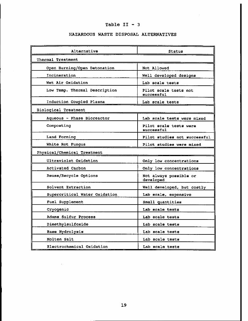
Table II - 3
HAZARDOUS WASTE DISPOSAL ALTERNATIVES
Alternative Status
Thermal Treatment
Open Burning/Open Detonation Not Allowed
Incineration Well developed designs
Wet Air Oxidation Lab scale tests
Low Temp. Thermal Description Pilot scale tests not successful
Induction Coupled Plasma Lab scale tests
Biological Treatment
Aqueous - Phase Bioreactor Lab scale tests were mixed
Composting Pilot scale tests were successful
Land Forming Pilot studies not successful
White Rot Fungus Pilot studies were mixed
Physical/Chemical Treatment
Ultraviolet Oxidation Only low concentrations
Activated Carbon Only low concentrations
Reuse/Recycle Options Not always possible or developed
Solvent Extraction Well developed, but costly
Supercritical Water Oxidation Lab scale, expensive
Fuel Supplement Small quantities
Cryogenic Lab scale tests
Adams Sulfur Process Lab scale tests
Dimethylsulfoxide Lab scale tests
Base Hydrolysis Lab scale tests
Molten Salt Lab scale tests
Electrochemical Oxidation Lab scale tests
19
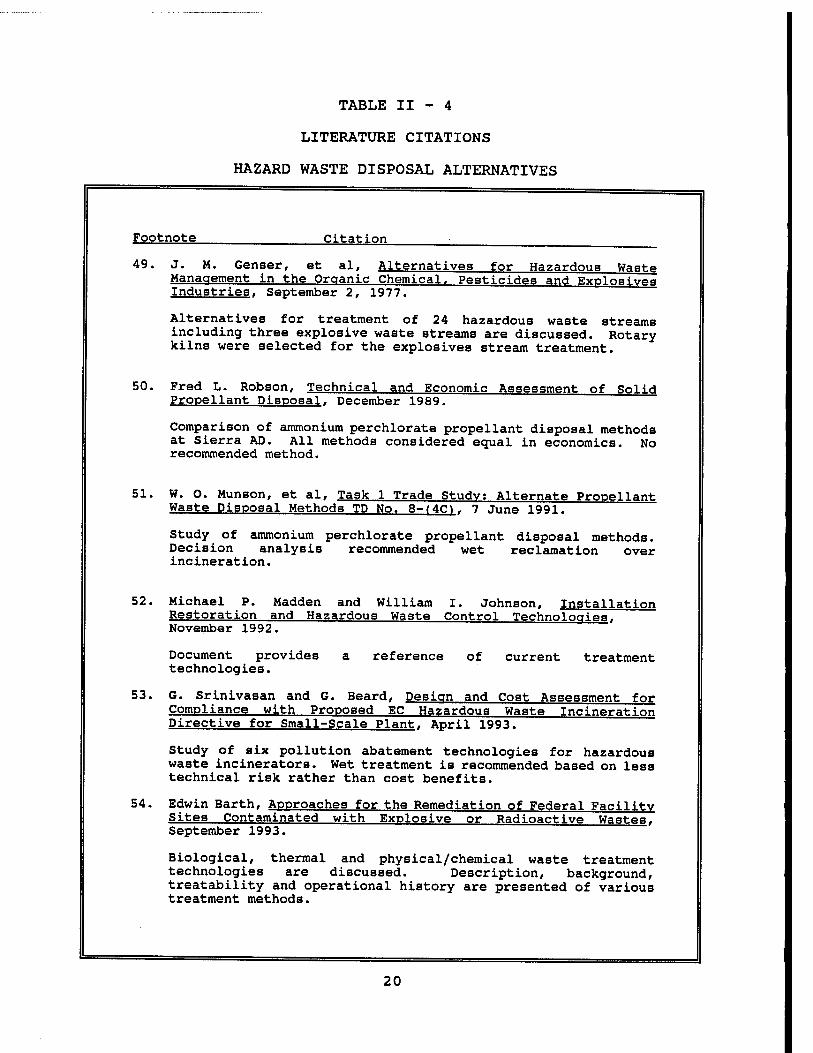
TABLE II - 4
LITERATURE CITATIONS
HAZARD WASTE DISPOSAL ALTERNATIVES
Footnote Citation
49. J. M. Genser, et al, Alternatives for Hazardoua Waste Management in the Organic Chemical. Pesticides and Explosives Industries. September 2, 1977.
Alternatives for treatment of 24 hazardous waste streams including three explosive waste streams are discussed. Rotary kilns were selected for the explosives stream treatment.
50. Fred L. Robson, Technical and Economic Assessment of Solid Propellant Disposal. December 1989.
Comparison of ammonium perchlorate propellant disposal methods at Sierra AD. All methods considered equal in economics. No recommended method.
51. W. O. Munson, et al, Task 1 Trade Study: Alternate Propellant Waste Disposal Methods TD No. 8-J4CI. 7 June 1991.
Study of ammonium perchlorate propellant disposal methods. Decision analysis recommended wet reclamation over incineration.
52. Michael P. Madden and William I. Johnson, Installation Restoration and Hazardous Waste Control Technologies. November 1992.
Document provides a reference of current treatment technologies.
53. G. Srinivasan and G. Beard, Design and Cost Assessment for Compliance with Proposed EC Hazardous Waste Incineration Directive for Small-Scale Plant. April 1993.
Study of six pollution abatement technologies for hazardous waste incinerators. Wet treatment is recommended based on less technical risk rather than cost benefits.
54. Edwin Barth, Approaches for the Remediation of Federal Facility Sites Contaminated with Explosive or Radioactive Wastes. September 1993.
Biological, thermal and physical/chemical waste treatment technologies are discussed. Description, background, treatability and operational history are presented of various treatment methods.
20
55. S. C. Torma, et al, Environmentally Safe Processing and Recycling of High-Energy Materials. 27 Feb-3 Mar 1994.
The paper reviews some of the technologies available for recycling high-energy yield explosives loaded projectiles. Explosives will be recycled to be used for industrial purposes in the mining industry. Propellants (ammonium nitrate and ammonium perchlorate) can be used in the agricultural industry as fertilizer. Some of the excess explosive material recovered may be incinerated to produce energy for steam production. Furthermore, this article reviews the developments in the bioremediation of explosive contaminated soils and industrial effluents.
56. Larry Sotsky, Demilitarization & D Technology for Conventional Munitions, 21-24 March 1994.
Paper discussed recent work with plasma arc furnace, super critical water oxidation technology and recycle/reuse of red phosphorus.
57. R. Eric Dotseth and David W. Ling, Munitions Demilitarization Through Disassembly and Resource Recovery. 21-24 March 1994.
Paper describes methods of disassembly and energetic material removal for cartridges, 90 mm through 106 mm.
58. Thomas J. Schilling, et al, Commercial Uses of Demilitarized Energetic Materials, 21-24 March 1994.
Paper reviewed the reprocessing and reuse programs at Crane Naval Surface Warfare Center in the development of commercial uses for surplus explosives, propellants and their constituents. Emphasis has been on RDX and HMX reuse in oil field services.
59. Dan Burch and Mike Johnson, Reformulation/Reuse of Explosives and Propellants, 21-24 March 1994.
Paper describes recent work of Naval Surface Warfare Center, Crane Division. They have concentrated on reclaiming energetics for commercial applications. Work has produced commercial mining explosives, metal brazing explosive, requalified RDX/HMX and use of gun propellant as a feed supplement and fertilizer.
60. D. S. Wulf man, et al, The Management of Recovered Polymer Bonded Explosives by Means of Reformulation. 21-24 March 1994.
Paper discusses the results of PBX reformulation studies. Reformulation can be accomplished with minimal environmental impact and results in "better" explosives than original.
61. Richard C. Doyle and Judith F. Kitchens, Composting of Soils/Sediments and Sludges Containing Toxic Organics Including High Energy Explosives. July 1993.
Describes laboratory and pilot experimentation to evaluate composting of explosive contaminated soils.
21
62. S. Thiboutot, et al, Biodearadation of Energetic Compounds; Application to Site Restoration. 21-24 March 1994.
This paper presented a Canadian study of biodegradation of RDX, TNT, NC and GAP material. Successful degradation occurred in concentrations up to 27,000 ppm in soil.
63. Lou D. Johnson and M. H. Spritzer, The Crvofracture Process for Chemical Munition Demilitarization, 21-24 March 1994.
Paper describes well developed process for demilitarizing chemical agent munitions. Rotary kiln thermal destruction was used for an overall 99.9999% DRE.
64. C. A. LaJeunesse, et al,Supercritical Water Oxidation of Colored Smoke, Dve, and Pyrotechnic Compositions, November 1993.
Describes supercritical incineration of wastes.
oxidation process to replace
65. L. L. Whinnery, et al, Processing Solid Propellants for Recycling, May 18-25, 1994.
Describes "cryocyling" demilitarization process.
66. David S. Ross, Disposal of Energetic Materials in Near Critical Water. 21-24 March 1994.
Paper on laboratory study of super critical water oxidation of energetic materials - AP, RDX, HMX, NG & TNT. Development appears safe and economical. Operating costs estimated at $700/ton.
67. James R. Hendricks and Joseph S. Klimek, Adams Process Demilitarizes Energetics. 21-24 March 1994.
Patented process demonstrated by bench scale test program. Process reacts organic materials in an atmosphere of elemental sulfur at 400-600°C.
68. Randall W. Hurd and George L. Clink, Energetic Materials Reclamation and Solvent Recycling. 21-24 March 1994.
HMX reclaimed by dimethylsulfoxide solvent recovery method presented in a paper. Laboratory work produced HMX product of 99.3% purity.
69. Millard M. Garrison and John Serino, Jr, The Conversion of Energetic Materials into Clean Alternate Commercial Energy Forms using Induction Coupled Plasma. 21-24 March 1994.
Paper describes thermal destruction treatment with argon induction coupled plasma torch at 10,000°C. DRE is up to 99.9999%.
70. & 76. William D. Siuri, Incinerator Alternatives Aim to Replace Flames. October 1994.
Article describes some new hazardous waste disposal methods under development.
22
71. T. M. Benziger, et al, Deatruction of Waste Energetic Materials Using Base Hydrolysis, 1993
Describes base hydrolysis test work to destroy high explosives.
72. T. Spontarelli, et al, An Engineered System Using Base Hydrolysis for Complete Disposal of Energetic Materials. 21-24 March 1994.
Paper describes safe, simple and inexpensive method to convert energetic material into non-energetic material. Material is decomposed at 60 to 150°C after 4 to 5 hours. Decomposition products include organic and inorganic salts with mostly nitrous oxide gaseous emission.
73. W. M. Bradshaw, Pilot-Scale Testing of a Fuel Oil - Explosives Cofiring Process for Recovering Energy from Waste Explosives, August 1988.
Proof of principle bench scale results are presented.
74. Craig A. Myler, et al, Use of Waste Energetic Materials as a Fuel Supplement, 1991.
Laboratory and bench scale work verify the principle while economics show a positive advantage.
75. Craig A. Myler, et al, Use of Waste Energetic Materials as a Fuel Supplement in Utility Boilers, 1994.
Laboratory and bench scale tests verify principle of mixing energetic wastes (TNT, RDX) with fuel oil is feasible and has an economic advantage.
77. Ravindra S. Upadhye and Bruce E. Watkins, Destruction of XM-46 (aka LGP-1846) Using the Motlen Salt Destruction Process. March 1994.
Describes a laboratory scale molten salt method to destroy high explosives.
78. Ravindra S. Upadhye, et al, Energetic Materials Destruction Using Molten Salt, May 23-25, 1994.
Describes a molten salt destruction process to destroy high explosives.
79. Timothy J. Tope and Walker F. Howell, Alternatives for Treatment of Waste Munitions Part I: The Role of Open Burning/Open Detonation, Summer 1994.
Article discusses technologies currently applied and being developed for demilitarization purposes, and an analysis of advantages and limitations of these technologies.
23
50
51
52
Fred L. Robson of United Technologies Research Center in 1989 prepared an assessment of disposal methods of its ammonium perchlorate (AP) scrap waste at Sierra Army Depot.50 Six alternatives were considered - open burning, rotary kiln incinerator, fluid bed incinerator, water AP recovery, ammonia AP recovery and supercritical water oxidation. Extensive cost data was presented. Disposal costs ranged from $1.50/lb. for supercritical water oxidation to 11$/lb. for on-site burning. No alternative was selected.
A trade study on methods of space shuttle propellant (AP) disposal was conducted by Thiokol Corporation in 1991. Eleven technologies were considered in an attempt to reduce open burning of waste and scrap propellant. Technologies included waste minimization, two types of incineration, biodegradation, supercritical oxidation, off-site destruction and four types of reclamation. After completing a decision matrix analysis and economic analysis, the AP wet cake reclamation approach was selected. Estimated disposal cost was 83<?/lb. The Tooele AD 1236 incinerator was also considered at a disposal cost of $1.05/lb.
The U.S. Army Corps of Engineers Toxic and Hazardous Materials Agency published the third edition of their handbook "Installation Restoration and Hazardous Waste Control Technologies" in 1992.52 The purpose of the handbook is to provide a reference of pertinent and current treatment technologies. Handbook information was derived from personal interviews with personnel directly involved in search, development and implementation of new and effective methods to accomplish the following: restoration of contaminated soils, groundwater and structures, and the minimization of the generation of hazardous waste materials. One hundred fifty-seven technical notes were summarized with fifty-one pertaining to hazardous waste control. Most of the notes referred to minimization, recovery and reuse.
Fred L. Robson (December 1989)
W. o. Munson, et al (7 June 1991)
Michael Madden and William Johnson (November 1992)
24
W. S. Atkins Consultants Limited, Surrey, UK, studied pollution abatement technologies for hazardous waste incinerators.53 Assessments and cost data for six gas cleaning design schemes were studied. Schemes included many combinations of process units — adsorption, dry bag and ceramic filters, wet scrubbing in void and packed towers, spray drier, venturi scrubber, ionizing wet scrubber and reaction vessels. Equipment was sized for 10,000 NM3/hr., at a cost from £ 590,000 to £ 923,000. Wet treatment schemes were recommended with all schemes meeting discharge criteria. Recommendation was based on less technical risk and a proven system.
The EPA's Center for Environmental Research Information developed a publication of approaches for remediation.54
Two technology transfer seminars during 1992 and 1993 were the basis for the publication. An overview of successfully demonstrated technologies was presented with background information, operation, applications, advantages and limitations cited. Emphasis was on remediating soil and groundwater contaminated with explosive. Chapter 5 lists the many treatment technologies. Incineration has been used at Cornhusker AAP, Louisiana AAP, Savanna AD and Alabama AAP.
Steven Torma et al, presented a paper at the Annual Meeting of the Minerals, Metals & Materials Society, reviewing some of the technologies available for recycling energetic projectiles.55 Recycling technology involves dismantling and separation of ammunition components into recyclable metals, plastics, paper and explosive materials. Explosives can be recycled to be used for industrial purposes in the mining industry. Propellants may be used in the agricultural industry as fertilizer or incinerated to produce heating steam. Other technologies discussed were supercritical water oxidation, plasma arc centrifugal furnace, and cryofracture. Munitions demilitarization is still mostly open burning/open detonation (82%) with incineration as the next most utilized method at only 10%. Other methods are used in less than 5% of the disposals.
The American Defense Preparedness Association sponsored an international symposium on "Energetic Materials Technology" March 21-24, 1994 at the Clarion Plaza Hotel, Orlando,
53 G. Srinivasan and G. Beard (April 1993)
54 Edwin Barth (September 1993)
Steve Torma, et al (3 March 1994)
25
55
56
57
58
Florida. Many papers were given on demilitarization technology focussing on reuse/recycle methods. The next five literature citations are papers given at the symposium.
Larry Sotsky, Project Leader with the Explosives and Demilitarization Section, U.S. Army Armament Research, Development and Engineering Center presented a paper describing three tasks developed to treat "difficult" energetic materials.56 A state-of-the-art plasma arc furnace was used to destroy pyrotechnic munitions at a DOE test site in Butte, Montana. Pyrotechnic compositions have also been destroyed with DRE > 99.99+% using supercritical water oxidation technology. The third task evaluated the recycle/reuse of red phosphorus/butyl rubber smoke grenade material. Initial results are favorable.
R. Eric Dotseth and David W. Ling of Mason & Hanger-Silas Mason Company, Inc. presented a paper to describe expanding the demilitarization and disassembly capabilities of the Iowa Army Ammunition Plant in support of the U.S. Army's efforts to move from open burning/open detonation toward resource recovery.57 This effort to expand the demilitarization capability included disassembly, energetic material removal, confined detonation, controlled incineration, and overall waste and hazard classification. Several processes and methods have been developed to perform this safely and environmentally. Their paper described the methods of disassembly and energetic material removal for high explosive and anti-personnel cartridges, 90mm through 106mm. These cartridges represent a significant portion of the munitions inventory slated for demilitarization, with a wide variety of explosive and propellant loads. A description of the decision process for determining the process for the demilitarization line, and the actual end result was discussed. Additionally, actual operating experience was described to show what went as planned and what obstacles arose during extended operation.
Thomas J. Schilling et al, presented a paper that reviewed the reprocessing and reuse programs at Crane Naval Surface Warfare Center in the development of commercial uses for surplus explosives, propellants and their constituents.58
Emphasis was on RDX and HMX reuse in oil field services.
Larry Sotsky (24 March 1994)
R. Eric Dotseth and David W. Ling (24 March 1994)
Thomas J. Schilling, et al (24 March 1994)
26
A high performance blasting agent for metal bonding applications was developed. High valued HMX was extracted for perforating charge applications. Recoverable yields were > 98% with a purity > 99.5%. A surplus energetics reprocessing pilot plant was being designed to manufacture 125 tons annually of blasting agent from surplus explosives.
A paper was presented to describe how the Naval Surface Warfare Center, has concentrated on reclaiming the valuable energetics with subsequent reformulating for commercial applications.59 Technology Development Inc. (TDI), Rolla, MO and TPL, Inc., Albuquerque, NM have demonstrated the feasibility of using reclaimed military explosives as commercial blasting agents on a lab/bench scale. TDI's efforts have concentrated on reformulation to produce a commercial mining explosive, while TPL has concentrated on producing a metal brazing explosive. In both cases, various reclaimed PBXs and other explosives have been reformulated and tested to produce explosives of equal or superior performance to current commercial explosives. Work has also been initiated to recover RDX and HMX from military explosives and propellants and to qualify the RDX and HMX for commercial applications. Tests conducted by TPL, Inc. indicate that a feed supplement for ruminant animals and a slow nitrogen release fertilizer can be generated from surplus Navy gun propellants. The feasibility of using surplus gun propellants in a novel oil and gas well stimulation process was also demonstrated.
The last reuse/recycle paper cited presented at the "Energetic Materials Technology" symposium was given by D. S. Wulf man of D. S. Wulf man and Associates, Inc.60 His paper discussed the results of ongoing reformulation studies begun in the late 1980s. Field applications of polymer bonded explosives were described. Reformulation can be accomplished with minimal environmental impact and the resulting explosives are in may instances theoretically "better" explosives than the original PBXs.
A report by Richard C. Doyle and Judith F. Kitchens for the U.S. Department of Energy (DOE) describes laboratory and pilot experimentation to evaluate composting of explosive contaminated soils at DOE's PANTEX plant.1 Laboratory
59
60
61
Dan Birch and Mike Johnson (24 March 1994)
D. S. Wulfman, et al (24 March 1994)
Richard C. Doyle and Judith F. Kitchens (July 1993)
27
62
63
64
65
studies were conducted using 14C-labeled explosives (RDX, HMX, PETN and TATB) contaminated soil loaded into horse manure/hay composts at rates up to 40% by weight. All explosives degraded rapidly and were reduced to below detection levels within three weeks. Data from the pilot scale studies generally were in agreement with the laboratory studies.
A Canadian Armed Forces sponsored paper presented a study on biodegration of energetic compounds (RDX, TNT, NC and GAP) ,62 Successful degradation occurred in concentra- tions up to 27,000 mg/kg. RDX mineralization rate reached 5 mg/kg/day when utilized as a nitrogen source under aerobic conditions.
The method for demilitarizing chemical agent munitions using the cryofracture process employs liquid nitrogen to condition munitions prior to fracture in a hydraulic press. A rotary kiln is used to destroy the munition cryofracture debris in the current U.S. plant design as described in the paper by General Atomics program manager Louis D. Johnson and his colleague M. H. Spritzer.63 The kiln exhaust gases are routed to an afterburner with 2 second residence time to ensure complete destruction of organic combustion products. Afterburner off-gases are treated in a pollution abatement system that removed acid gases and particulates. Agent destruction exceeded the detection limits, resulting in calculated DRE's greater than 99.999%.
A Sandia National Laboratory report by Costanzo A. La Jeunesse et al, describes the concept of a supercritical water oxidation reactor to destroy colored smoke, spotting dye and pyrotechnic munitions.64 Process and equipment operation parameters, process flow equations or mass balances and utility requirements for wastes are developed in this report. Two conceptual designs are developed with all process and instrumentation detailed. Concept is based on bench scale reactor work. Capital cost for a 20 lb/hr plant is $789,500 (1993$). Another Sandia National Laboratory poster presentation at the 1994 Joint USA-Russia Energetic Material Technology Symposium in Livermore, California on May 18-25, 1994 further described the cryoclying demilitarization process.65
S. Thiboutot (24 March 1994)
Lou D. Johnson and M. H. Spritzer (24 March 1994)
C. A. La Jeunesse, et al (November 1993)
L. L. Whinnery, et al (25 May 1994)
28
SRI International has conducted a study on the destruction of energetic materials in hydrothermal media near the critical temperature of water.66 The target materials included AP, RDX, HMX NG, TNT, ADN and CL-20. The bench scale work was conducted with liquid water at autogenous pressures at temperatures over the range 70°-350°C. It was found the simple reaction with water should provide a process yielding 5-nines destruction at or below 350°C. with residence times of 100-200 seconds. Preliminary cost estimates for a 300 lb/hr plant were $700,000 with an estimated operating cost of $700/ton.
Burns and Roe, Defense and Aerospace Division has developed the Adams Process, a potential chemical method that reacts organic materials in an atmosphere of elemental sulfur vapor (typically 450° to 600°C) .67 In this process, the organic materials are rapidly reacted to form a variety of simple sulfur compounds. The gaseous products are readily recovered or treated in conventional off-gas cleanup. Gaseous emissions from cleanup can be recycled back to the reactor. Bench scale tests on explosives has been performed with destruction complete within a four hour time frame. DRES's could be as high as 99.9999%.
HMX reclaimed by a dimethylsulfoxide (DMSO) solvent recovery method was discussed in a paper presented by Randall W. Hurd of Mason & Hanger - Silas Mason C., Inc.68
Laboratory work produced HMX product of 99.3% purity.
Millard M. Garrison of Alliant Techsystems, Inc. and John Serino of Plasma Technology Inc. presented a paper that described a thermal destruction treatment with an argon induction coupled plasma torch at 10,000°C.69 DRE is up to 99.9999%. No additional waste streams are generated. Initial test work was done at Drexel University. Several other groups of researchers are working on hot plasma techniques.70 The MIT Plasma Center in Cambridge, MA houses two 30 Kw plasma arc furnaces where hazardous material moves through a 10,000°C plasma arc developed by graphite electrodes. Researchers at Georgia Institute of Technology are working on a plasma torch to be used for in-
66
67
68
69
70
David S. Ross (24 March 1994)
James R. Hendrichs and Joseph S. Klimek (24 March 1994)
Randall W. Hurd and George L. Clink (24 March 1994)
Millard Garrison and John Serino (24 March 1994)
William D. Siuri (October 1994)
29
71
72
73
74
75
76
situ disposal methods. It is felt these plasma techniques can be cost competitive.
Two documents were found on base hydrolysis to destroy energetic materials. The first is a paper given by T. M. Benziger et al, of Los Alamos National Laboratory at the 1993 Incinerator Conference.71 The second paper on follow- up hydrolysis work at Los Alamos was given by a colleague Terry Spontarelli et al at the 1994 ADPA Energetic Materials Technical Symposium.72 These papers describe a safe, simple and inexpensive method to convert energetic materials (RDX, HMX, TNT, NC, NG, and NQ) into non- energetic materials. Materials were hydrolyzed with aqueous sodium hydroxide or ammonia. Material was decomposed at 60° to 150°C. after 4 to 5 hours. Decomposition products include organic and inorganic salts with mostly nitrous oxide gaseous emission. These products will require further treatment.
Three documents were found describing waste energetic materials used as a fuel supplement. The initial citation is the 1988 report of W. M. Bradshaw of Oak Ridge National Laboratory.73 His bench scale work presented proof-of- principle tests in a 300 Kw combustion furnace firing up to 40% TNT or 37% Comp B in Toluene/Fuel oil mixtures. The second citation is an article in the Journal of Hazardous Materials by Craig A. Myler et al.74 Their laboratory and bench scale work further verify the principle while economics presented show a positive advantage. The last fuel supplement citation also by Craig A. Myler presents additional results of their test work.7' Their most recent work will utilize a 498 KW boiler.
Based on technology originally developed at Lawrence Livermore National Laboratory, E. O. Systems, Inc. of Palo Alto, CA has developed a promising technique referred to as mediated electrochemical oxidation or MEO.76 MEO pumps liquid wastes through a closed loop system and destroys it in an acid electrolyte such as sulfuric acid. The waste
T. M. Benziger, et al (24 March 1994)
T. Spontarelli, et al (24 March 1994)
W. M. Bradshaw (August 1988)
Craig A. Myler, et al (1991)
Craig A. Myler, et al (1994)
William D. Siuri (October 1994)
30
materials are broken down into water and carbon dioxide. Upon completion, the acid can be regenerated and reused.
The last hazardous waste disposal alternative citations found were about the destruction of materials using molten salt. Both citations on the molten salt were by Ravindra S. Upadbye et al of Lawrence Livermore National Laboratory bench scale work.77 78 The molten salts are typically mixtures of alkali or alkaline earth carbonates and halides. The salts provide excellent heat transfer and reaction media, catalyze oxidation of organics and neutralize acid gases by forming stable salts such as sodium chloride. They have successfully and safely destroyed slurries of 35% HMX, RDX, PETN and TATB in mineral oil and 50% of the above in water. The temperature of the molten salt is varied between 400° to 900°C. They have also destroyed XM-46 liquid propellant. Destruction rates were 500 to 1000 grams per hour.
This section on review of waste disposal technologies concludes with an article by Timothy J. Tope and Walker F. Howell of the Radian Corporation, Oak Ridge, TN.79 Their article presents the role of open burning/open detonation, but discusses the disposal technologies currently applied and being developed for demilitarization purposes, and an analysis of advantages and limitations of these technologies. Table II - 5, Treatment/Disposal Options for Demilitarization of Ordnance summarizes their discussion. A comparison of their treatment alternatives is presented in Table II - 6, Comparative Analysis between treatment technologies. This comparison was conducted using five key criteria: Treatment effectiveness and application, environmental impacts/regulatory concerns, safety concerns, costs and degree of development. Table II - 6 indicates that most alternatives are not capable of treating explosive waste on a large scale bases.
The only developed technology other than open burning/open detonation is incineration. Other options may be developed but until there is a proven alternative incineration will be used at Badger AAP to replace open burning/open detonation for explosive waste disposal.
77 Ravindra S. Upadbye and Bruce E. Watkins (March 1994)
78 Ravindra S. Upadbye, et al (25 April 1994)
79 Timothy J. Tope and Walker F. Howell (Summer 1994)
31
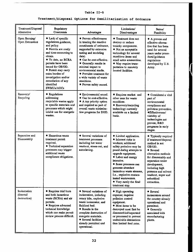
Table II-5
Treatment/Disposal Options for Demilitarization of Ordnance
Treatment/Disposal Regulatory Limitations/ Status/ Alternative Constraints Advantages Disadvantages Feasibility
Open Burning/ • Lack of specific • Proven effectiveness • Treatment does not • A proven and Open Detonation regulations .guidance, in treating the reactive destroy or reduce effective alterna-
and policy. constituents of ordnance, toxicity components. tive that has been • Permits are costly supported by extensive • Not an acceptable used for several and time-consuming to testing and modeling technology for several years under proce- obtain. data). munitions items and dural/guidance • To date, no RCRA • Can be cost-effective. small arms ammunition. regulations permits have been • Generally results in • May require trans- developed by U.S. issued for OB/OD. minimal impact to portation to remotely Army. • Permit may carry environmental media. located facilities. extra burden of • Provides treatment for investigation and/or a wide variety of waste remediation of any munitions. identified • Proven safety record. SWMUs/AOCs
Recovery/ • Regulations • Environmental sound. * Requires market and • Considered a vital Recycling addressing • Can be cost-effective. other uses for waste part of
recyclable wastes apply • A top priority option munitions. environmental to specific materials and and required as part of • Recovery/recycling compliance and processes which might overall waste minimiza- technology currently pollution prevention. inhibit use for energetic tion programs for DOD. available on a limited •Effectiveness/ wastes. basis. viability of
technologies not proven; R&D programs in early stages.
Separation and • Hazardous waste • Several variations of • Limited application. • Typically required Disassembly treatment permit treatment processes • Inherent risks to if treatment/disposal
required. including hot water workers; additional method is not • Technical separation washout, steam-out, and safety probelms may be OB/OD. processes may trigger autoclaving. posed during attempts to • Several additional waste upgrade equipment. alternative methods compliance obligations. • Labor and energy
intensive. • Some processes can generate abundant hazardous waste streams, I.e., explosive contam- inated wastewaters. • Very rarely the final treatment step.
for disassembly and separation under development, including high pressure and solvent washout, super and subcritical extraction.
Incineration • Requires trial burn • Several variations of • High operating • Several (thermal and both hazardous incineration, including expense; requires incinerators around destruction) waste (RCRA) and air rotary kiln, explosive pollution control the country already
permits. waste incinerator, and equipment. operational and • Requires advanced fluidized bed. • Most items to be permitted. technical knowledge • Results in the destroyed must first be • Generally which can make permit complete destruction of disassembled/separated associated with review process difficult. energetic materials. or processed to prevent manufacturing
• Several facilities undesirable detonations plants. already permitted and thus limited feed rates. operational.
32
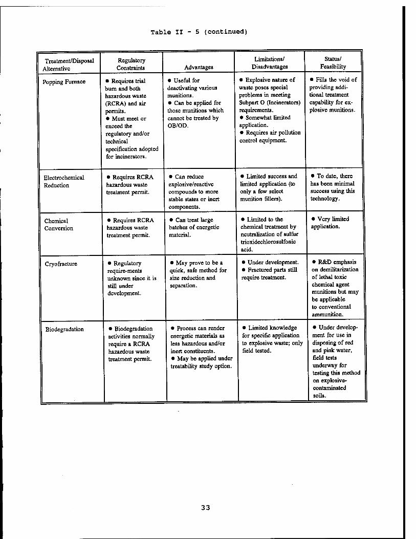
Table II - 5 (continued)
Treatment/Disposal Regulatory Limitations/ Status/
Alternative Constraints Advantages Disadvantages Feasibility
Popping Furnace • Requires trial • Useful for • Explosive nature of • Fills the void of
burn and both deactivating various waste poses special providing addi-
hazardous waste munitions. problems in meeting tional treatment
(RCRA) and air • Can be applied for Subpart 0 (Incinerators) capability for ex-
permits. those munitions which requirements. plosive munitions.
• Must meet or cannot be treated by • Somewhat limited
exceed the OB/OD. application.
regulatory and/or • Requires air pollution
technical control equipment.
specification adopted for incinerators.
Electrochemical • Requires RCRA • Can reduce • Limited success and • To date, there
Reduction hazardous waste explosive/reactive limited application (to has been minimal treatment permit. compounds to more only a few select success using this
stable states or inert munition fillers). technology. components.
Chemical • Requires RCRA • Can treat large • Limited to the • Very limited
Conversion hazardous waste batches of energetic chemical treatment by application.
treatment permit. material. neutralization of sulfur trioxidechlorosulfonic acid.
Cry o fracture • Regulatory • May prove to be a • Under development. • R&D emphasis
require-ments quick, safe method for • Fractured parts still on demilitarization
unknown since it is size reduction and require treatment. of lethal toxic
still under separation. chemical agent
development. munitions but may be applicable to conventional ammunition.
Biodegradation • Biodegradation • Process can render • Limited knowledge • Under develop-
activities normally energetic materials as for specific application ment for use in
require a RCRA less hazardous and/or to explosive waste; only disposing of red
hazardous waste inert constituents. field tested. and pink water,
treatment permit. • May be applied under treatability study option.
field tests underway for testing this method on explosive- contaminated
1 soils.
33
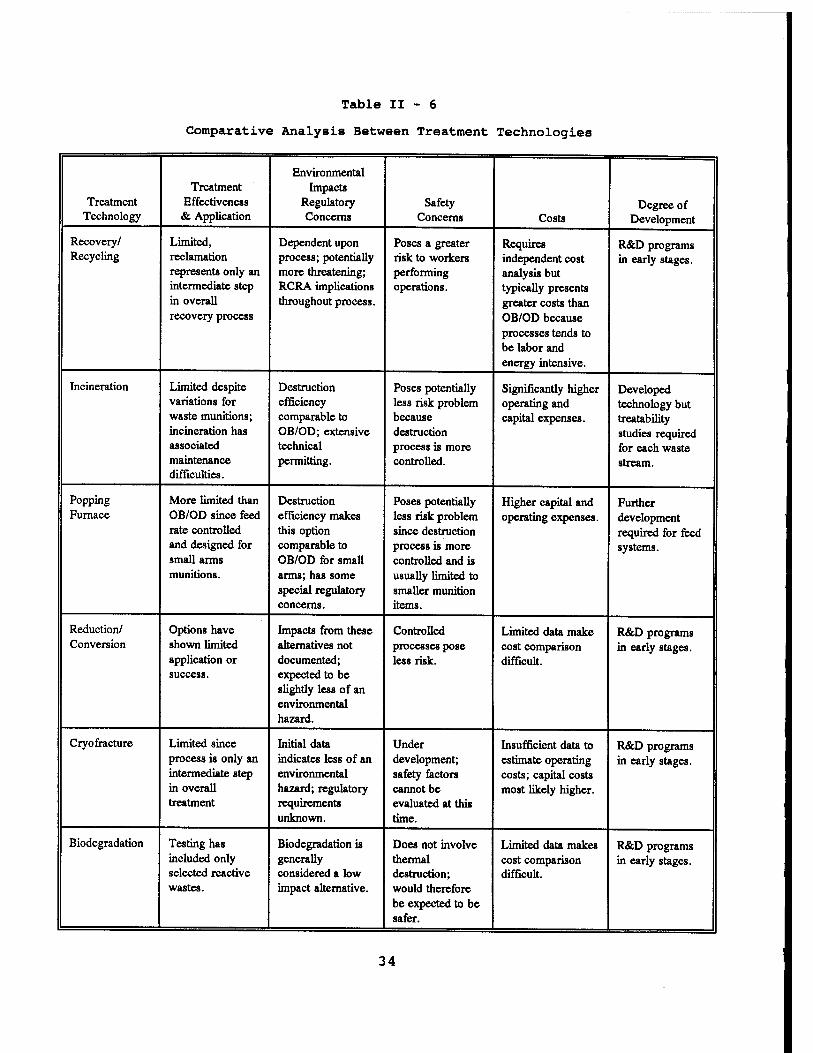
Table II - 6
Comparative Analysis Between Treatment Technologies
Environmental Treatment Impacts
Treatment Effectiveness Regulatory Safety Degree of Technology & Application Concerns Concerns Costs Development
Recovery/ Limited, Dependent upon Poses a greater Requires R&D programs Recycling reclamation process; potentially risk to workers independent cost in early stages.
represents only an more threatening; performing analysis but intermediate step RCRA implications operations. typically presents in overall throughout process. greater costs than recovery process OB/OD because
processes tends to be labor and energy intensive.
Incineration Limited despite Destruction Poses potentially Significantly higher Developed variations for efficiency less risk problem operating and technology but waste munitions; comparable to because capital expenses. treatability incineration has OB/OD; extensive destruction studies required associated technical process is more for each waste maintenance permitting. controlled. stream. difficulties.
Popping More limited than Destruction Poses potentially Higher capital and Further Furnace OB/OD since feed efficiency makes less risk problem operating expenses. development
rate controlled this option since destruction required for feed and designed for comparable to process is more systems. small arms OB/OD for small controlled and is munitions. arms; has some
special regulatory concerns.
usually limited to smaller munition items.
Reduction/ Options have Impacts from these Controlled Limited data make R&D programs Conversion shown limited alternatives not processes pose cost comparison in early stages.
application or documented; less risk. difficult. success. expected to be
slightly less of an environmental hazard.
Cry o fracture Limited since Initial data Under Insufficient data to R&D programs process is only an indicates less of an development; estimate operating in early stages. intermediate step environmental safety factors costs; capital costs in overall hazard; regulatory cannot be most likely higher. treatment requirements
unknown. evaluated at this time.
Biodegradation Testing has Biodegradation is Does not involve Limited data makes R&D programs included only generally thermal cost comparison in early stages. selected reactive considered a low destruction; difficult. wastes. impact alternative. would therefore
be expected to be safer.
34
4. Hazardous Waste Disposal Regulations
Current incinerator rules and regulations are briefly summarized in this paragraph and more fully developed in paragraph III-E. Specific literature citations may be found in Table H-7, Hazardous Waste Incinerator Regulations, Literature citations.
The first citation was a 1988 booklet prepared by the EPA's Office of Solid Waste.80 The booklet provides answers to questions that citizens may have about hazardous waste incineration. Questions of incineration technical aspects, regulations, permit process, permit process, general standards and potential risks are answered. Focus of information is its regulation under the Resource Conservation and Recovery Act (RCRA). Seventy eight questions are answered.
Todd A. Kimmell et al of the Argonne National Laboratory presented a paper describing the Munitions Provisions of the Federal Facility Compliance Act of 1992 which amended RCRA.81 This amendment subjects Federal facilities to the same incentives as the private sector for compliance. The paper reviewed several important Munitions Rule issues and discussed the impacts of these issues.
Michael Valenti, Associate Editor's article in the August 1993 issue of Mechanical Engineering discussed potential tighter EPA hazardous waste combustion emission standards.82 Proposed tighter particulate standards will limit emissions to 0.015 grain per dry standard cubic foot less than one-fifth the 0.08 grain now permitted. It will be expensive to retrofit to this standard that could alter the economics of incineration.
The EPA has prepared several documents to assist designer and operators of hazardous waste incinerators. An early citation from the EPA was a publication used at 1986 seminars for incinerator permit writers, inspectors and operators.83 The document is a compilation of papers presented by seminar speakers and was intended for use by those involved in the design, execution, reporting, and evaluation of trial burns. An EPA QA/QC handbook defines procedures for incinerator process monitoring, sampling and
80 Lori De Rose and Vanessa Musgrave (5 April 1988)
81 Todd A. Kimmell, et al (March 1994)
82 Michael Valenti (August 1993)
83 Norm Kulujian (September 1987)
35
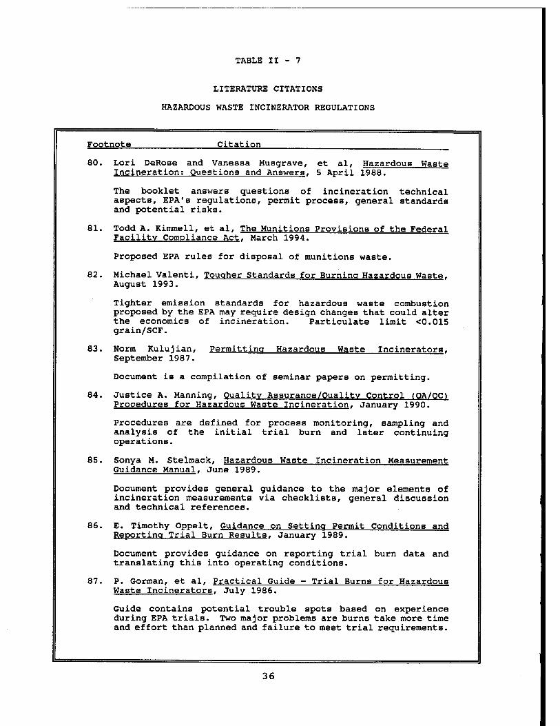
TABLE II - 7
LITERATURE CITATIONS
HAZARDOUS WASTE INCINERATOR REGULATIONS
Footnote Citation
80. Lori DeRose and Vanessa Musgrave, et al, Hazardous Waste Incineration; Questions and Answers. 5 April 1988.
The booklet answers questions of incineration technical aspects, EPA's regulations, permit process, general standards and potential risks.
81. Todd A. Kimmell, et al, The Munitions Provisions of the Federal Facility Compliance Act. March 1994.
Proposed EPA rules for disposal of munitions waste.
82. Michael Valenti, Tougher Standards for Burning Hazardous Waste. August 1993.
Tighter emission standards for hazardous waste combustion proposed by the EPA may require design changes that could alter the economics of incineration. Particulate limit <0.015 grain/SCF.
83. Norm Kulujian, Permitting Hazardous Waste Incinerators. September 1987.
Document is a compilation of seminar papers on permitting.
84. Justice A. Manning, Quality Assurance/Quality Control (OA/OC1 Procedures for Hazardous Waste Incineration. January 1990.
Procedures are defined for process monitoring, sampling and analysis of the initial trial burn and later continuing operations.
85. Sonya M. Stelmack, Hazardous Waste Incineration Measurement Guidance Manual. June 1989.
Document provides general guidance to the major elements of incineration measurements via checklists, general discussion and technical references.
86. E. Timothy Oppelt, Guidance on Setting Permit Conditions and Reporting Trial Burn Results. January 1989.
Document provides guidance on reporting trial burn data and translating this into operating conditions.
87. P. Gorman, et al, Practical Guide - Trial Burns for Hazardous Waste Incinerators. July 1986.
Guide contains potential trouble spots based on experience during EPA trials. Two major problems are burns take more time and effort than planned and failure to meet trial requirements.
36
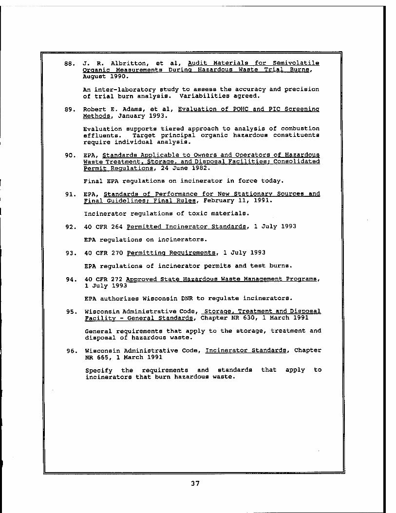
88. J. R. Albritton, et al, Audit Materials for Semivolatile Organic Measurementa During Hazardous Waste Trial Burns. August 1990.
An inter-laboratory study to assess the accuracy and precision of trial burn analysis. Variabilities agreed.
89. Robert E. Adams, et al, Evaluation of POHC and PIC Screening Methods, January 1993.
Evaluation supports tiered approach to analysis of combustion effluents. Target principal organic hazardous constituents require individual analysis.
90. EPA, Standards Applicable to Owners and Operators of Hazardous Waste Treatment. Storage, and Disposal Facilities; Consolidated Permit Regulations. 24 June 1982.
Final EPA regulations on incinerator in force today.
91. EPA, Standards of Performance for New Stationary Sources and Final Guidelines; Final Rules, February 11, 1991.
Incinerator regulations of toxic materials.
92. 40 CFR 264 Permitted Incinerator Standards. 1 July 1993
EPA regulations on incinerators.
93. 40 CFR 270 Permitting Reguirements. 1 July 1993
EPA regulations of incinerator permits and test burns.
94. 40 CFR 272 Approved State Hazardous Waste Management Programs, 1 July 1993
EPA authorizes Wisconsin DNR to regulate incinerators.
95. Wisconsin Administrative Code, Storage. Treatment and Disposal Facility - General Standards, Chapter NR 630, 1 March 1991
General requirements that apply to the storage, treatment and disposal of hazardous waste.
96. Wisconsin Administrative Code, Incinerator Standards. Chapter NR 665, 1 March 1991
Specify the requirements and standards that apply to incinerators that burn hazardous waste.
37
84
85
86
87
88
89
analysis of the initial trial burn and later continuing operations.84 The document emphasis is on quality assurance/quality control with guidance on plan preparation and analysis methods.
Another EPA handbook provides general guidance to reviewing the measurement aspects of incineration permit applications and trial burn plans.85 The guidance deals specifically with commonly required measurement parameters and measurement methods of process monitoring, sampling and analysis aspects of trial burns and subsequent operation. This document introduces the major elements of incineration measurement via checklists, general discussion and technical reference. EPA also published a handbook providing guidance on setting permit conditions, reporting trial burn results and translating these data into meaningful operating conditions.86 Sample forms are included. A previous 1986 EPA trial burn guide was also reviewed.87 The guide contains potential trouble spots based on experience during EPA trials. Two major problems are burns take more time and effort than planned and failure to meet trial requirements. An EPA sponsored study assessed the accuracy and precision of trial burn analysis.88 Variabilities between laboratories were in agreement. The most recent EPA regulatory work was an evaluation of principal organic hazardous constituents and on products of incomplete computation.89 Evaluation supports tiered approach to analysis of combustion effluents. Target principal organic hazardous constituents require individual analysis.
The specific explosive waste incinerator rules and regulations are titled below. These specific federal and state standards are the basic criteria for the facility. The regulations are:
Justice A. Manning (January 1990)
Sonya Stelmack (June 1989)
E. Timothy Oppelt (January 1989)
Gorman et al (July 1986)
J. R. Albritton (August 1990)
Robert Adams et al (January 1993)
38
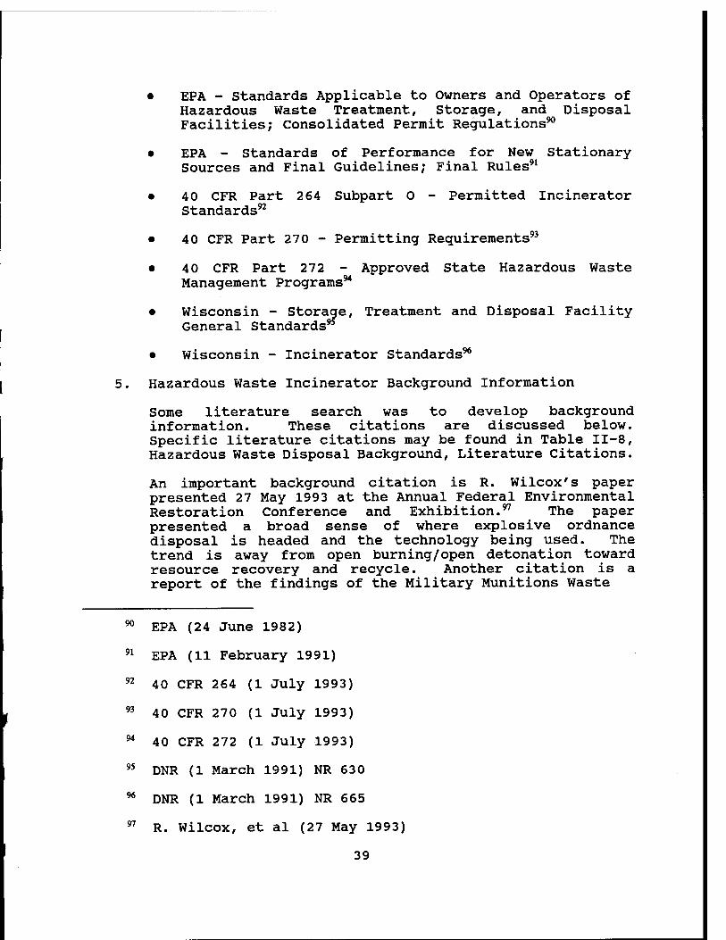
EPA - Standards Applicable to Owners and Operators of Hazardous Waste Treatment, Storage, and Disposal Facilities; Consolidated Permit Regulations90
EPA - Standards of Performance for New Stationary Sources and Final Guidelines; Final Rules91
40 CFR Part 264 Subpart 0 - Permitted Incinerator Standards92
40 CFR Part 270 - Permitting Requirements93
40 CFR Part 272 - Approved State Hazardous Waste Management Programs94
Wisconsin - Storage, Treatment and Disposal Facility General Standards9*
Wisconsin - Incinerator Standards96
5. Hazardous Waste Incinerator Background Information
Some literature search was to develop background information. These citations are discussed below. Specific literature citations may be found in Table II-8, Hazardous Waste Disposal Background, Literature Citations.
An important background citation is R. Wilcox's paper presented 27 May 1993 at the Annual Federal Environmental Restoration Conference and Exhibition.97 The paper presented a broad sense of where explosive ordnance disposal is headed and the technology being used. The trend is away from open burning/open detonation toward resource recovery and recycle. Another citation is a report of the findings of the Military Munitions Waste
90
91
92
93
94
95
96
97
EPA (24 June 1982)
EPA (11 February 1991)
40 CFR 264 (1 July 1993)
40 CFR 270 (1 July 1993)
40 CFR 272 (1 July 1993)
DNR (1 March 1991) NR 630
DNR (1 March 1991) NR 665
R. Wilcox, et al (27 May 1993)
39
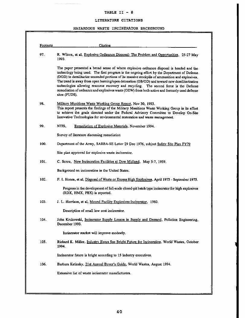
TABLE II - 8
LITERATURE CITATIONS
HAZARDOUS WASTE INCINERATOR BACKGROUND
Footnote Citation
97. R. Wilcox, et al, Explosive Ordinance Disposal: The Problem and Opportunities. 25-27 May 1993.
The paper presented a broad sense of where explosive ordnance disposal is headed and the technology being used. The first program is the ongoing effort by the Department of Defense (DOD) to demilitarize unneeded portions of its massive stockpile of ammunition and explosives. The trend is away from open burning/open detonation (OB/OD) and toward new demilitarization technologies allowing resource recovery and recycling. The second force is the Defense remediation of ordnance and explosives waste (OEW) from both active and formerly used defense sites (FUDS).
98. Military Munitions Waste Working Group Report. Nov 30, 1993. This report presents the findings of the Military Munitions Waste Working Group in its effort to achieve the goals directed under the Federal Advisory Committee to Develop On-Site Innovative Technologies for environmental restoration and waste management.
99. NTIS, Remediation of Explosive Materials. November 1994.
Survey of literature discussing remediation
100. Department of the Army, SARBA-SE Letter 29 Dec 1976, subject Safety Site Plan FY79
Site plan approved for explosive waste incinerator.
101. C. Sercu, New Incineration Facilities at Dow Midland. May 5-7, 1959.
Background on incineration in the United States.
102. F. I. Honea, et al, Disposal of Waste or Excess High Explosives. April 1973 - September 1975.
Progress in the development of full-scale closed-pit batch type incinerator for high explosives (RDX, HMX, PBX) is reported.
103. J. L. Harrison, et al, Mound Facility Explosives Incinerator. 1980.
Description of small low cost incinerator.
104. John Krukowski, Incinerator Supply Lesson in Supply and Demand. Pollution Engineering, December 1993.
Incinerator market will improve modestly.
105. Richard K. Miller, Industry Execs See Bright Future for Incineration. World Wastes, October 1994.
Incinerator future is bright according to 15 industry executives.
106. Barbara Katinsky, 21st Annual Buyer's Guide. World Wastes, August 1994.
Extensive list of waste incinerator manufacturers.
40
Working Group.98 These goals for innovative environmental restoration and waste management goals are discussed.
National Technical Information Service performed a literature search entitled, "Remediation of Explosive Materials" that was used.99
Another background citation was the approval of Badge AAP's initial siting of an explosive waste incinerator on 29 December 1976.100
Other background citations pertain to early use of incineration and explosive waste incineration. Sercu describes the initial waster incinerator.101 Progress by Mason & Hanger, Silas Mason Company, Inc. toward explosive waste disposal incineration was reported from 1973 to 1975.102 An initial low cost explosive incinerator was described for the Department of Energy.103
The availability of commercial waste incineration equipment was investigated. Several citations were found on this topic. Two recent market surveys were found - William T. Lorenz's survey of December 1993104 and Richard K. Miller's October 1994 survey.105 An extensive listing of waste incinerator vendors was found in "World Wastes" August 1994 Buyer's Guide Issue.106
98 Military Munitions Waste Working Group Report (30 Nov 1993)
99 NTIS (November 1994)
DA, Government Letter (29 December 1976)
C. Sercu (7 May 1959)
F. I. Honea, et al (1973-1975)
J. L. Harrison, et al (1980)
104 John Krukowski (December 1993)
105 Richard K. Miller (October 1994)
Barbara Katinsky (August 1994)
41
100
101
102
103
106
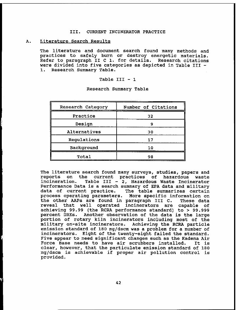
III. CURRENT INCINERATOR PRACTICE
A. Literature Search Results
The literature and document search found many methods and practices to safely burn or destroy energetic materials. Refer to paragraph II C 1. for details. Research citations were divided into five categories as depicted in Table III - 1. Research Summary Table.
Table III - 1
Research Summary Table
Research Category Number of Citations
Practice 32
Design 9
Alternatives 30
Regulations 17
Background 10
Total 98
The literature search found many surveys, studies, papers and reports on the current practices of hazardous waste incineration. Table III - 2, Hazardous Waste Incinerator Performance Data is a search summary of EPA data and military data of current practice. The table summarizes certain process operating parameters. More specific information on the other AAPs are found in paragraph III C. These data reveal that well operated incinerators are capable of achieving 99.99 (the RCRA performance standard) to > 99.999 percent DREs. Another observation of the data is the large portion of rotary kiln incinerators including most of the military on-site incinerators. Achieving the RCRA particle emission standard of 180 mg/dscm was a problem for a number of incinerators. Eight of the twenty-eight failed the standard. Five appear to need significant changes such as the Kadena Air Force Base needs to have air scrubbers installed. It is clear, however, that the particulate emission standard of 180 mg/dscm is achievable if proper air pollution control is provided.
42
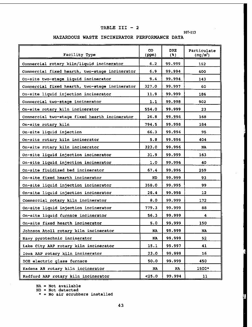
TABLE III - 2
HAZARDOUS WASTE INCINERATOR PERFORMANCE DATA 107-113
Facility Type CO
(ppm) DRE (%)
Particulate (mg/m3)
Commercial rotary kiln/liquid incinerator 6.2 99.999 152
Commercial fixed hearth, two-stage incinerator 6.9 99.994 400
On-site two-stage liquid incinerator 9.4 99.994 143
Commercial fixed hearth, two-stage incinerator 327.0 99.997 60
On-site liquid injection incinerator 11.9 99.999 186
Commercial two-stage incinerator 1.1 99.998 902
On-site rotary kiln incinerator 554.0 99.999 23
Commercial two-stage fixed hearth incinerator 26.8 99.996 168
On-site rotary kiln 794.5 99.998 184
On-site liquid injection 66.3 99.994 95
On-site rotary kiln incinerator 5.8 99.996 404
On-site rotary kiln incinerator 323.0 99.996 NA
On-site liquid injection incinerator 31.9 99.999 163
On-site liquid injection incinerator 1.0 99.996 40
On-site fluidized bed incinerator 67.4 99.996 259
On-site fixed hearth incinerator ND 99.999 93
On-site liquid injection incinerator 358.0 99.995 99
On-site liquid injection incinerator 28.4 99.998 12
Commercial rotary kiln incinerator 8.0 99.999 172
On-site liquid injection incinerator 779.3 99.999 88
On-site liquid furnace incinerator 56.3 99.999 4
On-site fixed hearth incinerator 5.0 99.999 150
Johnson Atoll rotary kiln incinerator NA 99.999 NA
Navy pyrotechnic incinerator NA 99.999 52
Lake City AAP rotary kiln incinerator 15.1 99.997 41
Iowa AAP rotary kiln incinerator 23.0 99.999 16
DOE electric glass furnace 50.0 99.999 450
Kadena AB rotary kiln incinerator NA NA 1500*
Radford AAP rotary kiln incinerator <25.0 99.994 11
NA = Not available ND = Not detected * = No air scrubbers installed
43
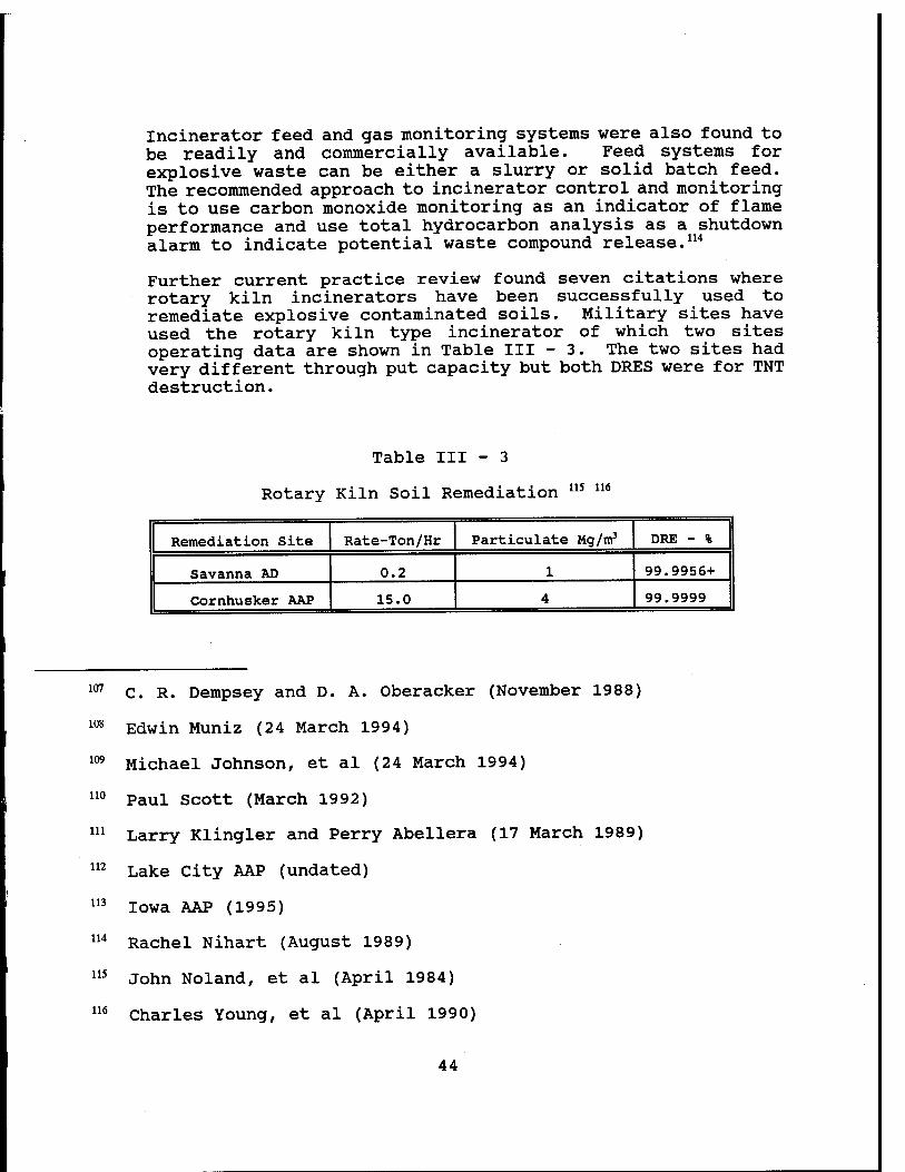
Incinerator feed and gas monitoring systems were also found to be readily and commercially available. Feed systems for explosive waste can be either a slurry or solid batch feed. The recommended approach to incinerator control and monitoring is to use carbon monoxide monitoring as an indicator of flame performance and use total hydrocarbon analysis as a shutdown alarm to indicate potential waste compound release.114
Further current practice review found seven citations where rotary kiln incinerators have been successfully used to remediate explosive contaminated soils. Military sites have used the rotary kiln type incinerator of which two sites operating data are shown in Table III - 3. The two sites had very different through put capacity but both DRES were for TNT destruction.
Table III - 3
Rotary Kiln Soil Remediation 115 116
Remediation Site Rate-Ton/Hr Particulate Mg/m3 DRE - %
Savanna AD 0.2 1 99.9956+
Cornhusker AAP 15.0 4 99.9999
107
108
109
110
C. R. Dempsey and D. A. Oberacker (November 1988)
Edwin Muniz (24 March 1994)
Michael Johnson, et al (24 March 1994)
Paul Scott (March 1992)
111 Larry Klingler and Perry Abellera (17 March 1989)
112 Lake City AAP (undated)
Iowa AAP (1995)
Rachel Nihart (August 1989)
John Noland, et al (April 1984)
Charles Young, et al (April 1990)
113
114
115
116
44
Personnel from ARDEC Large Calibre Weapons Systems Laboratory during the early 1970s studied various types of explosive waste incinerators. They recommended a fluid bed incinerator over rotary kiln incinerator based on economics and higher combustion inefficiencies. But Allegany Ballistics Laboratory found the system unsafe. Currently few fluid bed incinerators are used for explosive waste.
B. Incinerator Technology 117
117
Different incineration technologies have been developed for handling the various types and physical forms of hazardous waste. The four most common incinerator designs are liquid injection, rotary kiln, fixed hearth and fluidized bed incinerators.
The process of selecting and designing hazardous waste incineration systems can be very complex. Fortunately, considerable industrial manufacturing experience exists and many useful design guides have been published. A generalized review of the most prominent features of incineration systems and important design factors will be helpful in understanding a thermal destructor's operation and emissions performance.
The four major subsystems which may be incorporated into a hazardous waste incineration system are waste preparation and feeding, combustion chamber(s), air pollution control and residue/ash handling. The selection of the appropriate combination of these components is primarily a function of the physical and chemical properties of the waste steam or streams to be incinerated.
1. Waste Preparation and Feeding
The physical form of the waste determines the appropriate feed method. Liquids are blended, then pumped into the combustion chambers through nozzles or via specially designed atomizing burners. Wastes containing suspended particles may need to be screened to avoid clogging of small nozzle or atomizer openings. While sustained combustion is possible with waste heat content as low as 4,000 Btu/lb, liquid wastes are typically blended to a net heat content of 8,000 Btu/lb or greater, if possible. To incinerate lower heating value wastes, supplementary fuel will normally be required. Blending may be achieved by either mixing the wastes before they are fed to the combustion chamber or by using separate nozzles for different types of waste, wherein the mixing occurs in the combustion chamber.
C. R. Dempsey and E. T. Oppelt (January 1993)
45
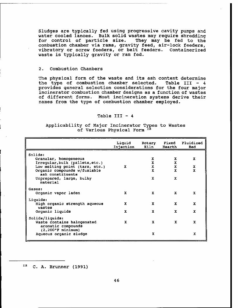
Sludges are typically fed using progressive cavity pumps and water cooled lances. Bulk solid wastes may require shredding for control of particle size. They may be fed to the combustion chamber via rams, gravity feed, air-lock feeders, vibratory or screw feeders, or belt feeders. Containerized waste is typically gravity or ram fed.
2. Combustion Chambers
The physical form of the waste and its ash content determine the type of combustion chamber selected. Table III - 4 provides general selection considerations for the four major incinerator combustion chamber designs as a function of wastes of different forms. Most incineration systems derive their names from the type of combustion chamber employed.
Table III - 4
Applicability of Major Incinerator Types to Wastes of Various Physical Form u*
Liquid Injection
Rotary Kiln
Fixed Hearth
Fluidized Bed
Solids: Granular, homogeneous Irregular,bulk (pallets,etc.) Low melting point (tars, etc.) Organic compounds w/fusiable
ash constituents
X
X X X X
X X X X
X
X X
Unprepared, large, bulky material
X X
Gases: Organic vapor laden X X X X
Liquids: High organic strength aqueous wastes
X X X X
Organic liquids X X X X
Solids/liquids: Waste contains halogenated
aromatic compounds (2,200°F minimum)
X X X X
Aqueous organic sludge X X
118 C. A. Brunner (1991)
46
Liquid injection incinerators or combustion chambers are applicable almost exclusively for pumpable liquid waste. These units (Figure III - 1) are usually simple, refractory- lined cylinders equipped with one or more waste burners. Liquid wastes are injected through the burners, atomized to fine droplets and burned in suspension. Burners, as well as separate waste injection nozzles, may be oriented for axial, radial or tangential firing. Improved utilization of combustion space and higher heat release rates, however, can be achieved with the utilization of swirl or vortex burners or designs involving tangential entry.
Good atomization is critical to achieving high destruction efficiency in liquid combustors. Nozzles have been developed to produce mists with mean particle diameters as low as 1 micron, compared to typical oil burners which yield droplets in the 10 to 50 /xm range. Atomization may be attained by low pressure air or steam (1 to 10 psig), high pressure air or stream (25 to 100 psig), or mechanical (hydraulic) means using specially designed orifices.
Vertically downward oriented liquid injection incinerators are preferred when wastes are high in inorganic salts and fusible ash content, while horizontal units may be used with low ash waste. In the past, the typical capacity of liquid injection incinerators was roughly 30 X 106 Btu/h heat release. However, units as high as 210 X 106 Btu/h are now in operation.
Rotary kiln incinerators (Figure III - 2) are more versatile in the sense that they are applicable to the destruction of solid wastes, slurries and containerized waste as well as liquids. Because of this, these units are most frequently incorporated into commercial off-site incineration facility designs and utilized for Superfund remediation. The rotary kiln is a horizontal cylindrical refractory-lined shell that is mounted on a slight slope. Rotation of the shell provides for transportation of waste through the kiln as well as enhanced mixing of the burning solid waste. The waste may move either concurrent or countercurrent to the gas flow. The residence time of waste solids in the kiln is generally 0.5 to 1.5 hours. This is controlled by the kiln rotation speed (typically 0.5 to 1.0 revolutions per minute), the waste feed rate, and in some instances, the inclusion of internal dams to retard the rate of waste movement through the kiln. The feed rate is also generally adjusted to limit the amount of waste being processed in the kiln to at most 20 percent of the kiln volume.
47
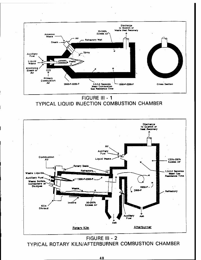
Olacharga to Quaocn or
Wut« H*«t Racovary
Auxiliary Fual
Liquid Wart« "
Atomizing Staam or
Air
Primary Combuatlon
AJr 250OF-3000-F 0J-2J3 Saeonda Waan Cornbuatlon
Gaa Raaldanea Tim*
Croaa Section
FIGURE III - 1 TYPICAL LIQUID INJECTION COMBUSTION CHAMBER
Olscharga to Quancfi or Haot flacoTary
Cornbuatlon Air
W«*ta Ltqul
Auxiliary Fu«4 Wmim SolWa, ContaJnac» of'
SHjdga«
Exoaa* AJr
.1.<W.0 Saconea Waan G*»
Raatdaoca TInva
Rafractory
Auxiliary Aart Fua4
RtfinrKHn Affrteurnf
FIGURE III - 2 TYPICAL ROTARY KILN/AFTERBURNER COMBUSTION CHAMBER
48

The primary function of the kiln is to convert solid wastes to gases, which occurs through a series of volatilization, destructive distillation and partial combustion reactions. An afterburner is necessary, however, to complete the gas-phase combustion reactions. The afterburner is connected directly to the discharge end of the kiln where the gases exiting the kiln are directed to the afterburner chamber. Some more recent systems have installed a "hot cyclone" between the kiln and afterburner to remove solid particles that might otherwise create slagging problems in the afterburner. The afterburner itself may be horizontally or vertically aligned, and essentially functions much on the same principles as a liquid injection incinerator. In fact, many facilities also fire liquid hazardous waste through separate waste burners in the afterburner. Both the afterburner and kiln are usually equipped with an auxiliary fuel firing system to bring the units up to temperature and to maintain the desired operating temperatures. On the other hand, some operators make it a practice of firing their aqueous waste streams into the afterburner as a temperature control measure. Rotary kilns have been designed with a heat release capacity as high as 150 X 106 Btu/h in the United States. On average, however, units are typically around 60 X 106 Btu/h.
Fixed hearth incinerators, also called controlled air, starved air or pyrolytic incinerators, are the third technology in use for hazardous waste incineration today. These units employ a two-stage combustion process, much like rotary kilns (Figure III - 3). Waste is ram fed or pumped into the first stage or primary chamber, and burned at roughly 50 to 80 percent of stoichiometric air requirements. This starved air condition causes most of the volatile fraction of the waste to be vaporized by the endothermic heat provided by the oxidation of the fixed carbon fraction. The resultant smoke and pyrolytic products consisting primarily of methane, ethane and other hydrocarbons; carbon monoxide and products of combustion pass to the second stage, or secondary chamber. Here, additional air is injected to complete the combustion which can occur either spontaneously or through the addition of supplementary fuels. The primary chamber combustion reactions and turbulent velocities are maintained at low levels by the starved-air conditions to minimize particulate entrainment and carryover. With the addition of secondary air, total excess air for fixed hearth incinerators is in the 100 to 200 percent range.
Fixed hearth units tend to be of smaller capacity than liquid injection of rotary kiln incinerators because of physical limitations in ram-feeding and transporting large amounts of waste material through the combustion chamber. These lower relative capital costs and potentially reduced particulate control requirements make them more attractive than rotary kilns for smaller on-site installations.
49
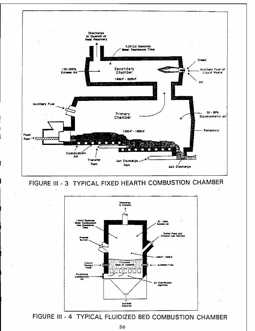
CH ach arg« to Qu*nc*i or H«*X Baeovary
0.2S-2J Sacooda Uaan RaaJAanc» TbiM
100-200% Exs**a Air
StMm
Auxiliary Fu*l or Liquid Wast«
Auxiliary Fu#»
F—6
50-80% Stolchlom*trle aJr
Rtfractory
A»h WaeÄars«. Rani Aah Dlacharg«
FIGURE III - 3 TYPICAL FIXED HEARTH COMBUSTION CHAMBER
to Cyworw
FIGURE III - 4 TYPICAL FLUIDIZED BED COMBUSTION CHAMBER
50
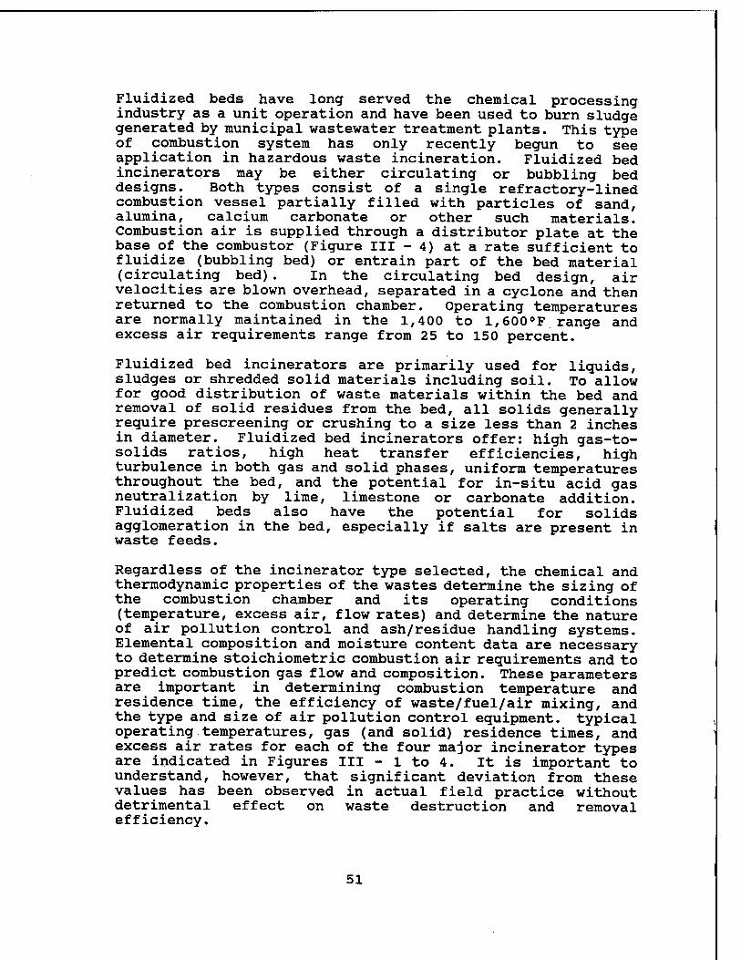
Fluidized beds have long served the chemical processing industry as a unit operation and have been used to burn sludge generated by municipal wastewater treatment plants. This type of combustion system has only recently begun to see application in hazardous waste incineration. Fluidized bed incinerators may be either circulating or bubbling bed designs. Both types consist of a single refractory-lined combustion vessel partially filled with particles of sand, alumina, calcium carbonate or other such materials. Combustion air is supplied through a distributor plate at the base of the combustor (Figure III - 4) at a rate sufficient to fluidize (bubbling bed) or entrain part of the bed material (circulating bed). In the circulating bed design, air velocities are blown overhead, separated in a cyclone and then returned to the combustion chamber. Operating temperatures are normally maintained in the 1,400 to 1,600°F range and excess air requirements range from 25 to 150 percent.
Fluidized bed incinerators are primarily used for liquids, sludges or shredded solid materials including soil. To allow for good distribution of waste materials within the bed and removal of solid residues from the bed, all solids generally require prescreening or crushing to a size less than 2 inches in diameter. Fluidized bed incinerators offer: high gas-to- solids ratios, high heat transfer efficiencies, high turbulence in both gas and solid phases, uniform temperatures throughout the bed, and the potential for in-situ acid gas neutralization by lime, limestone or carbonate addition. Fluidized beds also have the potential for solids agglomeration in the bed, especially if salts are present in waste feeds.
Regardless of the incinerator type selected, the chemical and thermodynamic properties of the wastes determine the sizing of the combustion chamber and its operating conditions (temperature, excess air, flow rates) and determine the nature of air pollution control and ash/residue handling systems. Elemental composition and moisture content data are necessary to determine stoichiometric combustion air requirements and to predict combustion gas flow and composition. These parameters are important in determining combustion temperature and residence time, the efficiency of waste/fuel/air mixing, and the type and size of air pollution control equipment, typical operating.temperatures, gas (and solid) residence times, and excess air rates for each of the four major incinerator types are indicated in Figures III - 1 to 4. It is important to understand, however, that significant deviation from these values has been observed in actual field practice without detrimental effect on waste destruction and removal efficiency.
51
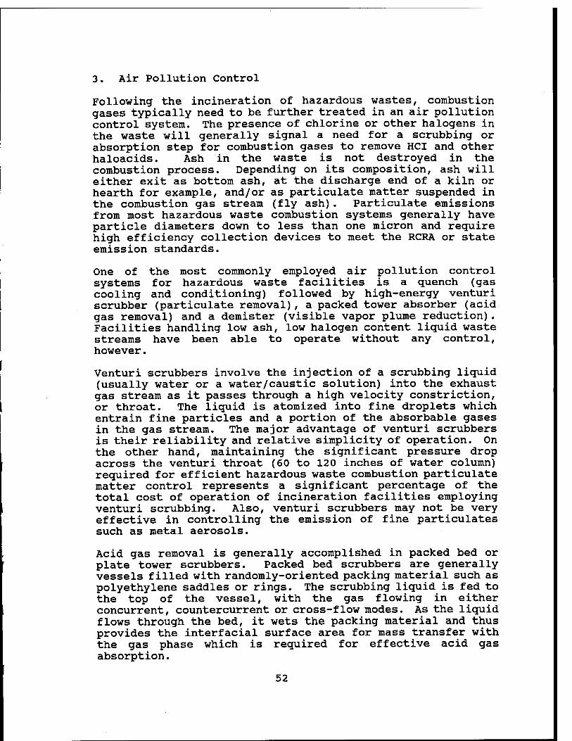
3. Air Pollution Control
Following the incineration of hazardous wastes, combustion gases typically need to be further treated in an air pollution control system. The presence of chlorine or other halogens in the waste will generally signal a need for a scrubbing or absorption step for combustion gases to remove HCI and other haloacids. Ash in the waste is not destroyed in the combustion process. Depending on its composition, ash will either exit as bottom ash, at the discharge end of a kiln or hearth for example, and/or as particulate matter suspended in the combustion gas stream (fly ash). Particulate emissions from most hazardous waste combustion systems generally have particle diameters down to less than one micron and require high efficiency collection devices to meet the RCRA or state emission standards.
One of the most commonly employed air pollution control systems for hazardous waste facilities is a quench (gas cooling and conditioning) followed by high-energy venturi scrubber (particulate removal), a packed tower absorber (acid gas removal) and a demister (visible vapor plume reduction). Facilities handling low ash, low halogen content liquid waste streams have been able to operate without any control, however.
Venturi scrubbers involve the injection of a scrubbing liquid (usually water or a water/caustic solution) into the exhaust gas stream as it passes through a high velocity constriction, or throat. The liquid is atomized into fine droplets which entrain fine particles and a portion of the absorbable gases in the gas stream. The major advantage of venturi scrubbers is their reliability and relative simplicity of operation. On the other hand, maintaining the significant pressure drop across the venturi throat (60 to 120 inches of water column) required for efficient hazardous waste combustion particulate matter control represents a significant percentage of the total cost of operation of incineration facilities employing venturi scrubbing. Also, venturi scrubbers may not be very effective in controlling the emission of fine particulates such as metal aerosols.
Acid gas removal is generally accomplished in packed bed or plate tower scrubbers. Packed bed scrubbers are generally vessels filled with randomly-oriented packing material such as polyethylene saddles or rings. The scrubbing liquid is fed to the top of the vessel, with the gas flowing in either concurrent, countercurrent or cross-flow modes. As the liquid flows through the bed, it wets the packing material and thus provides the interfacial surface area for mass transfer with the gas phase which is required for effective acid gas absorption.
52
Like packed bed scrubbers, plate scrubbers also rely on absorption for the removal of contaminants. The basic design is a vertical cylindrical column with a number of plates or trays inside. The scrubbing liquid is introduced at the top plate and flows successively across each plate as it moves downward to the liquid outlet at the tower bottom. Gas comes in at the bottom of the tower and passes through openings in each plate before leaving through the top. Gas absorption is promoted by the breaking up of the gas phase into small bubbles which pass through the volume of liquid on each plate.
Packed bed or plate tower scrubbers are commonly used at liquid injection incinerator facilities, where absorption of soluble gaseous pollutants (HCI & sulfur oxides) is often most important and particulate control is less critical. At rotary kiln or fixed hearth facilities, or liquid injection facilities where high ash content wastes are incinerated, however, venturi scrubbers are often used in series with packed bed or plate tower scrubbers.
Many designs have begun to incorporate waste heat boilers as a substitute for gas quenching and as a means of energy recovery. Wet electrostatic precipitators, ionizing wet scrubbers, collision scrubbers, spray dryer absorbers, and fabric filters are also being incorporated into newer systems. This is largely due to their high removal efficiencies for small particles and lower pressure drop.
4. Residue and Ash Handling
The inorganic components of hazardous wastes are not destroyed by incineration. These materials exit the incineration system either as bottom ash from combustion chamber, as contaminants in scrubber waters and other air pollution control residues, and in small amounts in air emissions form the stack. Residues generated from the incineration of hazardous waste must be managed carefully.
Ash is commonly either air-cooled or quenched with water after discharge from the combustion chamber. From this point, ash is frequently accumulated on-site in storage lagoons or in containers prior to disposal in a permitted hazardous waste land disposal facility. Dewatering or chemical fixation/stabilization may also be applied to meet the Land Disposal Restriction regulations prior to disposal.
Air pollution control residues are generated from the combustion gas quenching, particulate removal, and acid gas absorption steps in an incineration system. These residues are typically aqueous streams containing entrained particulate matter, absorbed acid gases (usually as HCI), salts, and trace
53
amounts of organic contaminants. These streams are often collected in sumps or recirculation tanks where the acids are neutralized with caustic and returned to the process. Eventually, a portion or all of these waters must be discharged for treatment and disposal. Many facilities discharge neutralized waters to settling lagoons or to a chemical precipitation step to allow for suspended contaminants to be concentrated and ultimately sent to land disposal. Depending upon the nature of the dissolved contaminants and their concentration after treatment, waters may either be returned to the process or discharged to sewers. One alternative to the management of aqueous residue streams is to use dry scrubber systems which do not generate any wastewater.
C. Incinerators at Other AAP's U9 m m m
Operating explosive waste incinerators burning wastes similar to Badger AAP's are located at three Army Ammunition Plants - Radford, Lake City and Iowa. Each system is based on a rotary kiln incinerator. Lake City and Iowa's systems were derived from the Tooele AD APE 1236 deactivation furnace. Radford AAP has two identical rotary kiln incinerators, 440 and 441.
1. Incinerator Equipment
Radford incinerators are designed to incinerate off- specification or waste production propellant mixtures. These mixtures are brought from the production area to the grinding building, where they are ground and mixed with water. The resulting slurry is three parts water to one part propellant. A pump system located in the grinding building supplies both incinerators with this slurry feed on a continuous basis. The incinerators are operated 24 hrs/day, 365 days/year with minimal downtime. A wide variety of propellant mixtures are burned in the incinerators. Each incinerator system has a feed system, rotary kiln, afterburner, evaporative cooler, fabric filter, gas precooler, packed-bed liquid scrubber, exhaust fan, exhaust stack and brine system. A process schematic and flow sheet is shown in Figure III - 5, Radford Explosive Waste Incinerator Process Schematic and Figure III - 6, Radford AAP EWI Process Flow Diagram.
119
120
121
122
Lake City AAP (undated)
Iowa AAP (1994)
Tooele AD (June 1994)
DRE Technologies (1992)
54
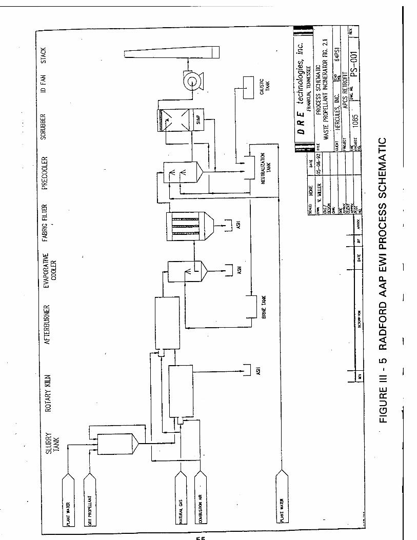
CD CO ZD
o CO
cc
o o o UJ
Q.
OS
CO
I8
on UJ
C3
l< l<
3^
— 5 £
Ul
%t
O O
I CO Q_
Ö a.
o
Ii
e
^
i< L
rt1
>- OS <c i— o a;
CO ^
-Hi
CO o
ss«
£
Egg
T
-H
JT
A A A
5
S
A
y <
LU I (J C/3
C/D CO UJ U O cc Q_
Q_ < <
Q CC O LL Q < CC
if)
LU CC Z) o
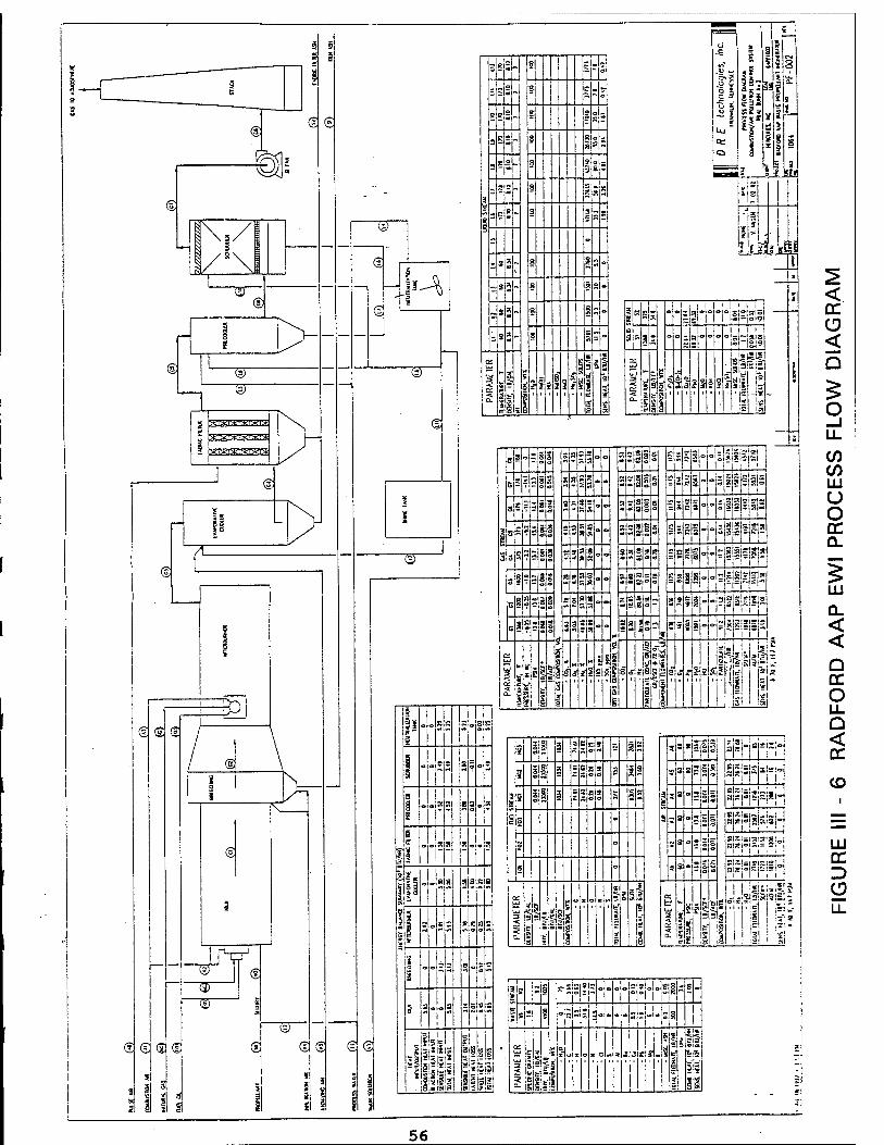
®
€
@ S
J"V ®
® <3 <3 s vs>
<S
gj® § g
3JS2.~ 8 Sr»
=|s2~ § Es»
o es. I Iss
a 5 SJ1 »*~ 3 ?|f~ § i?gs
3 "2- S g5g
ESp ? IS?
-
; S2~ 8 |jo
= *2- § ä s-
s 3*- § Ss«
= s*- 3 5 ~ o * al - ft -
OS UJ
UJ a -< c
S3if -3 s . g äi*w i g = 2l*!al!ftff 3- 3 f 5 ' ' ' ' ' ' ' = *
»2 =
itljl
1 '' 1' 8 R* Sis e|=|3i9i o I 1 M ass: " z a "~ "\sb\*\*
* ► g - " 'ap!<=:S
iiii-iliimsfk! is J | e" 8 ' ' 1' |= -]*
LI
Jin »PIllü ÜilB
911 Slsl m
a«|(
=i?!?l=j5i
■St»
«3 i •
3 s sjljll II I h > i 3 3 3 2 sS sJ5|S ahi
ä 3 3 -Wss sjsjsji 5i'!i S3 3 - s z c «islei-i-i-i i
= S - ; o o aisisisis'gl«,!
' 3 - 3 a 0 SJSJäjüjsill-j
OS
UJ 2 ■< 2 2
B
| £ f f 4
li s 9L-:2
"Si
*msi
«itijii
3 g i
... B si!
I !
°l -
* i=|- - - - sisLLls | "Si"
S .
T 2 c ü+ = sl=i=|-!s a Mill
1 1
OS
UJ
I o-l 'I SIS
« x c > »|a » i j J f
1 M Sail ft*
JI8
56
Lake City's explosive waste incinerator consists of an oil- fired APE 1236 rotary kiln with an air pollution control system. The rotary kiln is designed to incinerate configured munitions and bulk explosives. Incineration is not at capacity all the time, nor is it a continuous operation for some waste items. Wastes are fed at rates based on safety requirements designed to eliminate any high-order detonations. Over 50 types of munitions and explosives are typically destroyed. The waste items enter the system at the cool end of the kiln and move toward the burner end. Kiln temperature is maintained by modulating the burner between low-fire and high-fire. A screen is provided at the outlet to separate the ash and scale from the recyclable metals. An after burner is used to enhance combustion and to guarantee complete destruction of explosives. The air pollution control system is designed for removal of particulate and hazardous waste constituents from the incinerator exhaust gases. This system consists of two gas coolers, a cyclone, baghouse, exhaust fan and stack. The cyclone removes the large particles and baghouse removes the small particles. A process schematic is shown in Figure III - 7, Lake City Explosive Waste Incinerator Flow Diagram.
Iowa's furnace/incinerator is also a Tooele design APE 1236 oil fired rotary kiln with an air pollution control system similar to Lake City's. The incineration system is designed to demilitarize obsolete or unserviceable ammunition items and to dispose of bulk propellants, explosives or pyrotechnic wastes generated during the process of manufacture and assembly. Waste is fed at a specific rate depending on the item. Bulk materials are loaded into paper bags for placement on the input conveyor. A feed monitor scale prevents feeding over the allowed rate. Waste enters the rotary kiln via two conveyors from the cold end as at Lake City. The kiln or retort consists of four cast-steel sections bolted end to end. Spiral flights within the kiln provide physical separation of quantities of munitions or explosives. Normally bulk explosives begin to burn in the first or second kiln sections and are consumed by the third or fourth sections. Most munitions should begin burning, deflagrate or detonate within the middle sections. After processing through the kiln, ash and metal components are discharged by conveyor. The Iowa AAP air pollution control system consists of the same components as the Lake City system. General arrangement of the furnace/incinerator is shown in Figure III-8, Iowa AAP Deactivation Furnace/EWI.
57
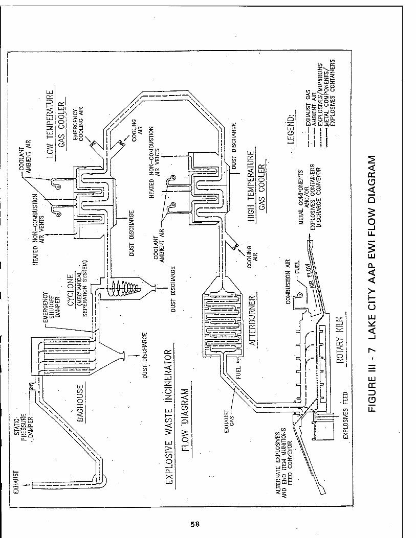
< cc CD < Q
O _j LL
LU
Q_ < <
> H U LU
<
LU CC
58
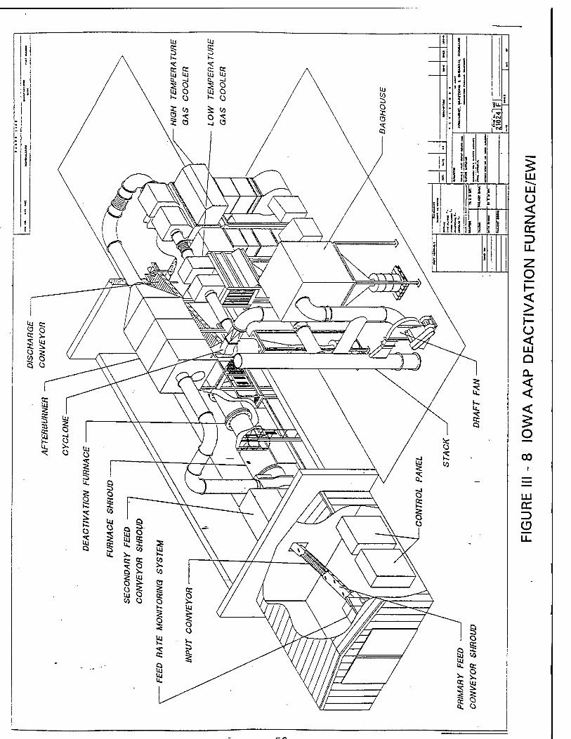

2. Incinerator Equipment Comparison
The three explosive waste in incinerators are similar but also very different. Table III - 5, Incinerator Comparison presents the similarity and differences. Lake City and Iowa's incinerator is the long-time standard item in AMCCOM's inventory. The two systems are almost identical, especially the air control systems and feed rate. Iowa has a one foot larger diameter kiln and is fired with #2 fuel oil rather than #1. Radford's incinerator is significantly different than the other two AAP's. Waste feed is pumped to the incinerator as water slurry at three times the rate of the other bulk solid fed incinerators. The Radford kiln volume is three times greater to conform with the increased feed rate and the configuration is different - twice the diameter and one-half of length. Natural gas is the primary Radford fuel with the kiln having a 35% greater energy input. But the Radford afterburner is much smaller, one-third of energy input of the APE 1236 system. The balance of the Radford air control system is also very different. An evaporator cooler rather than air heat exchanger is used to cool the combustion gas. Cooling media is brine versus air. Radford's Bartlett Snow system has a water spray gas precooler and packed bed liquid scrubber but has no large particle separation cyclone. All three AAP's have a fabric baghouse, but Radford has 2% times the baghouse collection fabric area, comparable to a three times design feed rate.
Operating parameters of the three explosive waste incinerators are different. Table III - 6, Incinerator Operating Data presents a comparison of the different operating data. The most significant difference is the Radford incinerator operates at a hotter temperature than the two 1236 incinerators. Both kiln temperature and afterburner temperature is hundreds of degrees hotter. Also the kiln residence time is one-half but the afterburner residence time is twice as long. The air flow rates are comparable. Another difference is the exist temperature. It is different for all three systems.
60
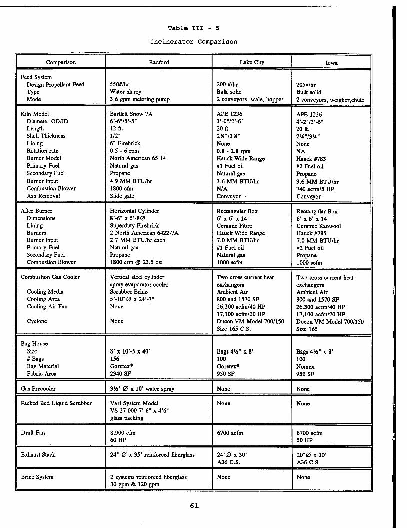
Table III - 5
Incinerator Comparison
Comparison Radford Lake City Iowa
Feed System Design Propellant Feed 550#/hr 200 #/hr 205#/hr Type Water slurry Bulk solid Bulk solid Mode 3.6 gpm metering pump 2 conveyors, scale, hopper 2 conveyors, weigher.chute
Kiln Model Bartlett Snow 7A APE 1236 APE 1236 Diameter OD/ID 6'-675*-5B 3'-072'-6" 4'-2"/3'-6" Length 12 ft. 20 ft. 20 ft. Shell Thickness 1/2" 2W73W" 2K73K" Lining 6" Firebrick None None Rotation rate 0.5 - 6 rpm 0.8 - 2.8 rpm NA Burner Model North American 65.14 Hauck Wide Range Hauck #783 Primary Fuel Natural gas #1 Fuel oil #2 Fuel oil Secondary Fuel Propane Natural gas Propane Burner Input 4.9 MM BTU/hr 3.6 MM BTU/hr 3.6 MM BTU/hr Combustion Blower 1800 cfin N/A 740 acfm/5 HP Ash Removal Slide gate Conveyor Conveyor
After Burner Horizontal Cylinder Rectangular Box Rectangular Box Dimensions 8'-6" x 5'-80 6' x 6' x 14* 6' x 6" x 14' Lining Superduty Firebrick Ceramic Fibre Ceramic Kaowool Burners 2 North American 6422-7A Hauck Wide Range Hauck #785 Burner Input 2.7 MM BTU/hr each 7.0 MM BTU/hr 7.0 MM BTU/hr Primary Fuel Natural gas #1 Fuel oil #2 Fuel oil Secondary Fuel Propane Natural gas Propane Combustion Blower 1800 cfm @ 23.5 osi 1000 scfm 1000 scfm
Combustion Gas Cooler Vertical steel cylinder Two cross current heat Two cross current heat spray evaporator cooler exchangers exchangers
Cooling Media Scrubber Brine Ambient Air Ambient Air Cooling Area 5'-lO"0x24'-7" 800 and 1570 SF 800 and 1570 SF Cooling Air Fan None 26,300 acfm/40 HP 26.300 acfm/40 HP
17,100 acfm/20 HP 17,100 acfm/20 HP Cyclone None Ducon VM Model 700/150 Ducon VM Model 700/150
Size 165 C.S. Size 165
Bag House Size 8' x 10'-5 x 40' Bags 4'/4" x 8' Bags 4V4" x 8' #Bags 156 100 100 Bag Material Goretex* Goretex* Nomex Fabric Area 2340 SF 950 SF 950 SF
Gas Precooler 3V4' 0 x 10' water spray None None
Packed Bed Liquid Scrubber Vari System Model VS-27-000 7'-6" x 4'6" glass packing
None None
Draft Fan 8,900 cfm 6700 acfm 6700 acfm 60 HP 50 HP
Exhaust Stack 24" 0 x 35' reinforced fiberglass 24" 0 x30' 20" 0 x30' A36 C.S. A36 C.S.
Brine System 2 systems reinforced fiberglass 30 gpm & 120 gpm
None None
61
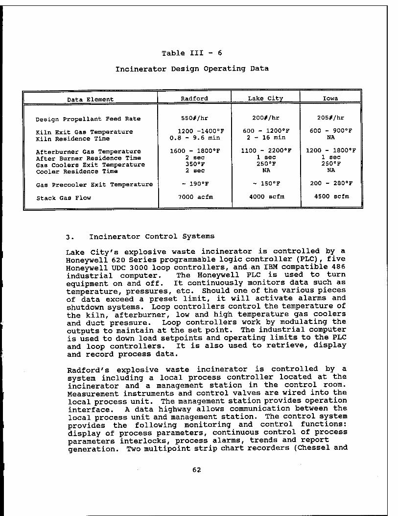
Table III - 6
Incinerator Design Operating Data
Data Element Radford Lake City Iowa
Design Propellant Feed Rate 550#/hr 200#/hr 205#/hr
Kiln Exit Gas Temperature Kiln Residence Time
1200 -1400°F 0.8 - 9.6 min
600 - 1200°F 2-16 min
600 - 900°F NA
Afterburner Gas Temperature After Burner Residence Time Gas Coolers Exit Temperature Cooler Residence Time
1600 - 1800°F 2 sec 350°F 2 sec
1100 - 2200°F 1 sec 250°F NA
1200 - 1800°F 1 sec 250°F NA
Gas Precooler Exit Temperature - 190°F - 150°F 200 - 280°F
Stack Gas Flow 7000 acfm 4000 scfm 4500 scfm
3. Incinerator Control Systems
Lake City's explosive waste incinerator is controlled by a Honeywell 620 Series programmable logic controller (PLC) , five Honeywell UDC 3000 loop controllers, and an IBM compatible 486 industrial computer. The Honeywell PLC is used to turn equipment on and off. It continuously monitors data such as temperature, pressures, etc. Should one of the various pieces of data exceed a preset limit, it will activate alarms and shutdown systems. Loop controllers control the temperature of the kiln, afterburner, low and high temperature gas coolers and duct pressure. Loop controllers work by modulating the outputs to maintain at the set point. The industrial computer is used to down load setpoints and operating limits to the PLC and loop controllers. It is also used to retrieve, display and record process data.
Radford's explosive waste incinerator is controlled by a system including a local process controller located at the incinerator and a management station in the control room. Measurement instruments and control valves are wired into the local process unit. The management station provides operation interface. A data highway allows communication between the local process unit and management station. The control system provides the following monitoring and control functions: display of process parameters, continuous control of process parameters interlocks, process alarms, trends and report generation. Two multipoint strip chart recorders (Chessel and
62
Honeywell) are used to record various process parameters. The recorders continuously record process parameters versus time. Flow rates are totalized and integrated over time and displays a value indicating pounds burned.
The Iowa explosive waste incinerator is operated and controlled by a Honeywell PLC similar to the Lake City incinerator. The PLC program provides the operation and feed rate parameters. The program also provides protection and automatic shutdown if there is a system failure. Its control system also includes five Honeywell UDC 3000 loop controllers and an IBM industrial computer. The computer provides an interface between the operator and the PLC and also provides a data collection point. The operating software is a package developed by Honeywell named the "Personal Computer Operating Station". This software is a menu driven package allowing the operator to move around twenty one different main display screens. Screens depict operating state, alarm state, history, set points, munition recipes, diagnostics, tuning, startup and shutdowns. The control scheme is shown on Figure III-9, Iowa AAP Functional Process Control Diagram.
All three explosive waste incinerator control systems are extensively interlocked such that if any emergency should occur, the waste feed is cut off. Certain process parameters are critical for destroying the waste and scrubbing the combustion gas. These critical parameters are interlocked so that waste feed is automatically shut off if certain limits are exceeded. Table III -7 Automatic Waste Feed Cut Off Conditions, is a list of these critical parameters for each location. Cut off parameters are similar for the three systems, but the cut off limits are very different depending on the RCRA permits.
63
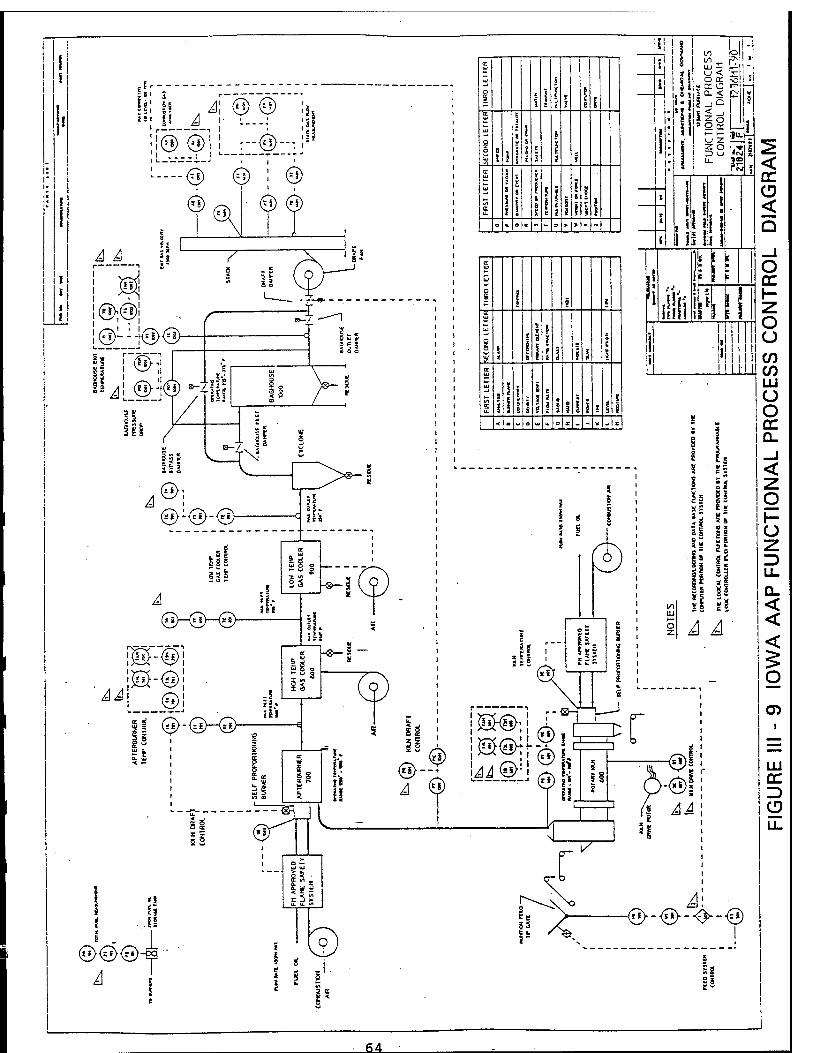
@"@
Ü 4
!(3)^ie<g>
^ (S>; (5>l<n>-<g>-
Ü
(3H3M3>-
m-<ü :| (^-(SK^
lü n
S3 H&-S
a: -g>— i
L
<$)
EC
O X
i 1 E
i X
i 1 1 S E
O 2 O B
t
6 i
1
i ' I \
I 5
I I i I i
UJ
S a.
i
\ I 8 S
i E
? 2
i 5
g
il o K a - = > *
tu
UJ
a i | 5 i
UJ
UJ
9 0 5 <
t i i
5
a
1 1 ? ! 3 1 5 5
l I
a
UJ
% U.
s
j s 1
i i 8
5 3 i t
8 3 I 1 f j I 1
< a - a w » o X - - * - c
! i H l ^ o I l
:il ö<£l!".! !| O CC i-o I li i I - a: o m- >—I
»o£
1,1 I I I I I I I I III I
< CC CD < Q
±1 IIC/)
■<5>-@>-0-©
_64_
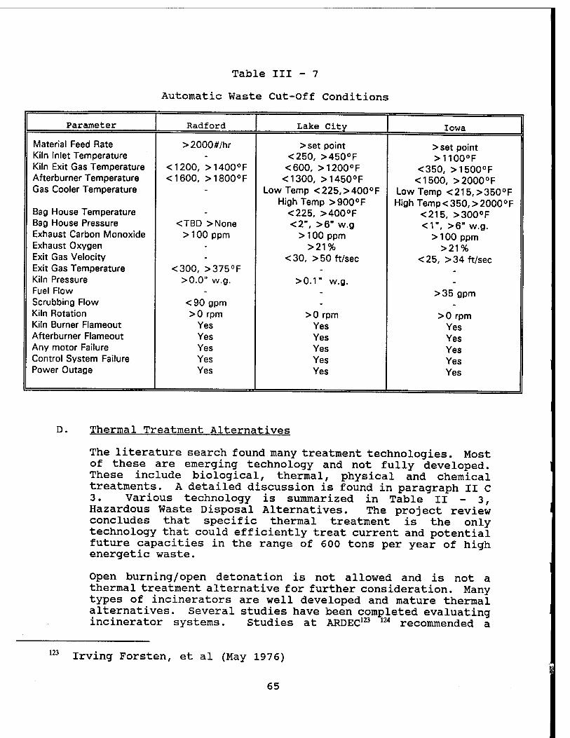
Table III - 7
Automatic Waste Cut-Off Conditions
Parameter Radford Lake City Iowa
Material Feed Rate >2000#/hr >set point >set point Kiln Inlet Temperature - <250, >450°F >1100°F Kiln Exit Gas Temperature <1200, >1400°F <600, >1200°F <350, >1500°F Afterburner Temperature <1600, >1800°F <1300, >1450°F <1500, >2000°F Gas Cooler Temperature - Low Temp <225,>400°F Low Temp <215,>350°F
High Temp >900°F High Temp < 350, > 2000°F Bag House Temperature - <225, >400°F <215, >300°F Bag House Pressure <TBD >None <2", >6" w.g <1", >6" w.g. Exhaust Carbon Monoxide >100 ppm > 100 ppm > 100 ppm Exhaust Oxygen - >21% >21% Exit Gas Velocity - <30, > 50 ft/sec <25, > 34 ft/sec Exit Gas Temperature <300, >375°F - . Kiln Pressure >0.0" w.g. >0.1" w.g. - Fuel Flow - - >35 gpm Scrubbing Flow <90 gpm - . Kiln Rotation >0 rpm >0 rpm >0 rpm Kiln Burner Flameout Yes Yes Yes Afterburner Flameout Yes Yes Yes Any motor Failure Yes Yes Yes Control System Failure Yes Yes Yes Power Outage Yes Yes Yes
D. Thermal Treatment Alternatives
The literature search found many treatment technologies. Most of these are emerging technology and not fully developed. These include biological, thermal, physical and chemical treatments. A detailed discussion is found in paragraph II C 3. Various technology is summarized in Table II - 3, Hazardous Waste Disposal Alternatives. The project review concludes that specific thermal treatment is the only technology that could efficiently treat current and potential future capacities in the range of 600 tons per year of high energetic waste.
Open burning/open detonation is not allowed and is not a thermal treatment alternative for further consideration. Many types of incinerators are well developed and mature thermal alternatives. Several studies have been completed evaluating incinerator systems. Studies at ARDEC123 m recommended a
123 Irving Forsten, et al (May 1976)
65
124
125
126
128
fluid bed incinerator over a rotary kiln incinerator, but fluid beds were later found to be unacceptable from a safety standpoint.125 Much rotary kiln development work has been completed by the EPA Incineration Research Facility at Jefferson, Arkansas126 and earlier by Blank and Wesselink & Associates.127 Blank and Wesselink & Associates established a standard design for disposal of explosive wastes at Army Ammunition Plants. The standard design is a rotary kiln as provided by Tooele Army Depot. Standard design and operating practice are very mature. The three similar explosive waste incinerators now in operation are rotary kiln incinerators. Badger AAP's incinerator will also be a rotary kiln incinerator based on the proven design from the three similar facilities.
The rotary kiln is probably the most prominent type of combustion system for incineration. These devices are popular because they can operate in a wide range of conditions and therefore can handle a wide range of wastes.128 Each rotary kiln operates under different conditions generating different emissions. For example, rotary kilns that devolatilize contaminated soil operate at temperatures as low as 500°F, while rotary cement kilns operate at temperatures as high as 2,800°F. Because of this variation, no single temperature is characteristic of a rotary kiln. Rotary kilns typically have fairly high entrainment. Entrainment occurs because solids roll over and over again inside the kiln, and are continually tumbled and reintroduced to the gas stream, providing multiple opportunities for them to become entrained. In addition, solids reside in the kiln a long time. Many rotary kilns are charged discretely; often entire drums are fed into a kiln in a single charge. This means that the temperature inside the kiln is cyclical. The material may be at a much higher temperature initially as the waste first begins to burn, and then at a lower temperature as the waste burns out before the next charge is added. Because of the temperature variability inside the kiln, the volatility of material may be much higher than would be expected from the average exit temperature. As a result, a single time-averaged exit temperature is not representative necessarily of the environment that materials experience in a rotary kiln. Therefore, rotary kilns are
Robert Scola and Joseph Santos (October 1978)
R. A. Knudson (June 1974)
Larry Waterland (June 1994)
127 Blank and Wesselink & Associates (March 1977)
Justice Manning (October 1993)
66
excellent explosive waste incinerators.
Current Rules and Regulations
Hazardous waste combustion devices are regulated under the Resource Conservation and Recovery Act (RCRA) under the following provisions:
• 40 CFR part 264, subpart 0 - Permitted Incinerator Standards
• 40 CFR part 270 - Permitting Requirements
The RCRA regulations require that all hazardous waste treatment, storage, and disposal facilities be permitted before being constructed. An exception is that existing facilities can continue to operate until EPA or "authorized" states make permit decisions.
The State of Wisconsin is authorized to administer and enforce a hazardous waste management program in lieu of the Federal program in accord with RCRA.129 The Wisconsin program as administered by the Department of Natural Resources was approved by EPA effective on January 31, 1986, June 6, 1989 and January 22, 1990. Wisconsin has primary responsibility for enforcing its hazardous waste program. However, EPA retains the authority to exercise its enforcement authority under RCRA. Wisconsin rules and regulations are contained in Wisconsin Administrative Code under the following chapters:
• Chapter NR 630 - Storage, Treatment and Disposal General Standards
• Chapter NR 665 - Incinerator Standards
Under section 40 CFR 264.340, certain incinerators that burn waste defined as hazardous based only on ignitability, corrosivity, or reactivity characteristics are exempted from most of the incinerator permit requirements. If the waste has either no or insignificant concentrations of hazardous waste constituents, the facility can be exempted from all of the permit requirements except for waste analysis and closure.
Three types of hazardous waste combustion devices are regulated under RCRA: incinerators, boilers, and industrial furnaces (BIFs). Different standards apply to incinerators than to BIFs.
Only enclosed devices with a direct flame are considered
129 40 CFR 272 (1 July 1993)
67
Only enclosed devices with a direct flame are considered incinerators and are subject to subpart 0 incineration standards. Thermal treatment devices that are not enclosed or that operate without a direct flame and that are not BIFs are regulated under subpart X, which requires that miscellaneous units undergo an environmental assessment. Open burning/open detonation is regulated under subpart X.
1. Incinerator Performance Standards
Regulations for hazardous waste incinerators apply to emissions of organics, hydrogen chloride, and particulate matter, as well as fugitive emissions. The performance standards for hazardous waste incinerators require a 99.99 percent destruction and removal efficiency (DRE) for designated principal organic hazardous constituents (POHCs). Since measuring the DRE for all organic constituents in the hazardous waste is impractical, EPA regulations specify that the DRE must be demonstrated on a subset of organics, POHCs, that are considered representative of the other organic constituents an incinerator will burn. POHCs are chosen based on such factors as difficulty of incineration and prevalence in the waste feed.
Hydrogen chloride and particulate emissions also are regulated. The required removal efficiency for hydrogen chloride is either 99 percent efficiency or a maximum of four pounds per hour emitted, whichever is greater. For particulates, the emissions limit is 0.08 grains per dry standard cubic foot (gr/dscf) corrected to 7 percent oxygen. This correction is required so that regardless of the dilution factor (the more dilution the greater the percentage of oxygen), the concentrations for different combustion devices under different operating parameters can be compared. EPA developed a new formula to calculate the correction to 7 percent oxygen that accounts for oxygen enrichment by allowing substitution of the actual percentage of oxygen in the incoming air. Note EPA is considering the potential to lower the particulate standard to 0.015 gr/dscf.130
Fugitive emissions from the combustion zone also must be controlled. The two control methods are (1) maintaining negative pressure in the combustion zone so that air will be pulled into the device rather than allowing pollutants to escape before they go through air pollution control equipment, and (2) totally sealing the combustion chamber so that no emissions can escape to the environment. A
130 Michael Valenti (August 1993)
68
delay time between an exceedance of the maximum combustion chamber pressure limit and automatic cutoff of the waste feed generally is not acceptable. Any delay between a pressure exceedance and an automatic waste feed cutoff potentially would result in fugitive emissions.
2. Incinerator Amendments
Requirements for metals and products of incomplete combustion (PICs) were proposed in April 1990 in the amendments to the incinerator regulations. The emission limits for metals are site specific and risk based, while the PICs regulations limit the carbon monoxide or hydrocarbons in stack gas. A site-specific, risk-based check on hydrogen chloride emissions similar in format to the metals requirements also was proposed. These incinerator amendments have been on hold. Nevertheless, incinerator permit writers have been implementing them since mid-1988 under the authority of the Omnibus provision in section 3005(c)(3) of RCRA. The Omnibus provision allows the permitting authority to impose permit conditions as necessary to protect human health and the environment. Both site-specific risk-based metals emission limits and PIC emission limits have been set in incinerator permits under the authority of the Omnibus provision. EPA personnel initially developed guidance on both metals emissions and PICs, but this guidance is out of date and is being revised.
A very important aspect of the regulations is that compliance with the operating conditions specified in the permit is deemed to be compliance with the performance standards. This provision exists because continuously monitoring the concentration of emitted pollutants, with the possible exception of hydrogen chloride, to evaluate compliance with the performance standards is not possible given the current state of technology. The permit, which is site specific, is based on the results of a trial burn in which compliance with the performance standards as well as key operating parameters, such as temperature, are monitored. The operating conditions under which the performance standards are met are specified as permit conditions. The regulations specify that a facility in compliance with the permit conditions is deemed to be complying with the performance standards. If, during the life of the permit, EPA receives information that indicates operating conditions no longer represent compliance with the performance standards, EPA can require a retest or can modify the permit.
69
3. Operating Conditions
The regulations require the following operating conditions to be specified in an incinerator permit (NR6655.09):
Carbon monoxide level in stack exhaust gas
Waste Feed rate and composition
Combustion temperature
Combustion gas velocity indicator
Other requirements necessary to meet performance standards
These conditions are self explanatory, except for the requirement for a combustion gas velocity indicator and the "other requirements." The combustion gas velocity indicator is important because it indicates gas residence time in the combustor.
To determine the other requirements, two questions must be addressed:
• What other operating conditions should be set in the permit to ensure long-term compliance with the performance standard?
• How can these permit conditions be set from the trail burn to account for variability such as differences in operating conditions from one run to the next?
Additional requirements under the incinerator regulations include:
• Automatic waste feed cutoff (NR665.09(12))
• Records, training, inspections and monitoring (NR665.09)
• Removal of hazardous waste and residues upon closure (NR665.10)
70
EPA developed guidance on setting permit conditions and reporting trial burn results.131 EPA's goals in developing the guidance were to provide a standard set of incinerator operating conditions that would ensure maintenance of performance standards during incinerator operation; eliminate unnecessary or redundant parameters that would restrict flexibility of operation and make monitoring to ensure compliance cumbersome; and include both the regulatory and technical basis for each operating condition. The basis for each operating condition was included for three reasons. First, the guidance was intended to be used as a training tool. Second, because all incinerators are different, the guidance would be difficult to apply in all situations without detailed information. By providing the basis for choosing permit conditions and determining how they are set, EPA allows the permit writer to evaluate the applicability of conditions to the particular incinerator being evaluated and, if necessary, adapt these operating conditions to a specific facility. Third, compliance with the guidance is not required; the document is only guidance. EPA concluded that permit writers were more likely to implement the guidance if they understood its bases.
4. Permitting Process
The permitting process for incinerators differs depending on whether a unit is a new, as-yet-unconstructed unit or an existing unit. For owner/operators of a new unit, the first step in the permitting process is to submit Parts A and B of the permit application. Part A is a standard form that describes the types of waste management units at the facility and the types and amount of waste the units will be handling. The much more detailed requirements for Part B are described in part 270 of the regulations. Wisconsin regulations refer to Part A and B as a Feasibility and Plan of Operation Report. Wisconsin regulations are in NR665.06. The purpose of the report is to determine whether the site has the potential for use as a hazardous waste incinerator and to identify and address any operating conditions which are necessary for the proper operation of the facility. After a facility has submitted Parts A and B, the permitting authority reviews the application and prepares either a draft permit or a draft denial. The proposed decision then is released for public comment. A public hearing will be held if requested during the public comment period. Finally, the permitting authority
131 E. T. Oppelt (January 1989)
71
incorporates the public comments, and, if the decision is to issue the permit, issues a four-phase permit.
The facility must comply with a set of operating conditions as per Wisconsin NR665.07 for each of the following four phases of operation:
• Startup/shakedown-bringing the equipment on line and resolving any problems.
• The trial burn-conducting the trial burn for purposes of demonstrating compliance.
• The post-trial burn period-assembling, analyzing, and reviewing the results of the trial burn.
• The final operations period-the rest of the facility operation under the permit.
Although the conditions for the final operations period are specified when the permit is issued, if the results of the trial burn are different than those expected, the conditions in that final phase of operation may be modified.
5. Future Strategy
The EPA developed a Draft Combustion Strategy in October 1993 to serve as a catalyst for discussion on how to best integrate hazardous waste source reduction and waste combustion and on ways to better assure the public of safe operations of hazardous waste combustion facilities.132
The foundation of this draft strategy are the following goals:
• To establish a strong preference for source reduction over waste management, and thereby reduce the long-term demand for combustion and other waste management facilities.
• To better address public participation in setting a national source reduction agenda, in evaluating technical combustion issues, and in reaching site specific decisions during the waste combustion permitting process.
132 Justice Manning (October 1993)
72
• To develop and impose implementable and rigorous state-of-the-art safety controls on hazardous waste combustion facilities by using the best available technologies and the most current science.
• To ensure that combustion facilities do not pose an unacceptable risk, and use the full extent of legal authorities in permitting and enforcement.
• To continue to advance scientific understanding with regard to waste combustion issues.
These goals address the major issues surrounding hazardous waste combustion today and provide an appropriate framework for a broad assessment of how source reduction and combustion of hazardous waste can be integrated into a national waste management program.
Specific relevant actions proposed by the draft strategy include the following short-term actions: Give low priority to new permits, finalize waste minimization program, use site specific risk assessments, and reduce particulate standard to 0.015 gr/dscfm. Some long term actions are reduction of sources, setting annual reduction goals and upgrade rules to reflect state-of- the-art advancements.
73
IV. EXISTING FACILITY FEASIBILITY
A. Existing Contaminated Waste Processor
1. General
Badger AAP has a small unit, contaminated waste processor (CWP) that was constructed in 1981-83, becoming operational in August 1983. It was subsequently laid away, mothballed in 1992. The CWP is a system designed to incinerate explosive contaminated combustible material or to flash explosive contaminated metal. The system consists of a carbottom furnace, batch feed system including an overhead trolly, and an air pollution control system (APCS). The system was designed to burn 300 pounds of waste per hour or flash 8000 pounds of metal per hour while meeting state and federal air pollution control standards. Actual incineration rates have been under 250 pounds/hour. Refer to drawings in Appendix for more information.
2. Furnace
The furnace is of a single chamber, self-moving carbottom type with a capacity for loading a 6 foot high by 6 feet wide by 13 foot long load of 10,000 pounds gross weight. It was manufactured by Wellman Thermal System. The nominal interior dimensions are 6 feet high by 6 feet 11 inches wide by 13 feet long. The furnace operates at a 1800°F maximum continuous working temperature with a capability of withstanding intermittent temperatures of 2000°F. #2 fuel oil fires the furnace. The furnace is operated as an induced draft furnace in conjunction with a dry-type air pollution control system. Included with the furnace is an unfired afterburner to provide a residence time of approximately 0.4 to 0.5 seconds for the exhaust gases at 1600°F. There is a stack above the unfired afterburner and a lateral connection from this stack to duct the exhaust gases to the air pollution control system (APCS). The stack is closed off above the lateral connection during normal operations by a butterfly damper. This damper will be opened and the stack used only when the APCS is shut down.
3. Batch Loading System
The batch loading system uses a 6 feet wide by 12 feet long by 2 feet high loading basket with a holding tray below. The basket is placed on the standard carbottom with an overhead traveling trolley loading system. The loading basket is fabricated of steel with wire braided sides and enclosed pan to catch the ash and residue.
74
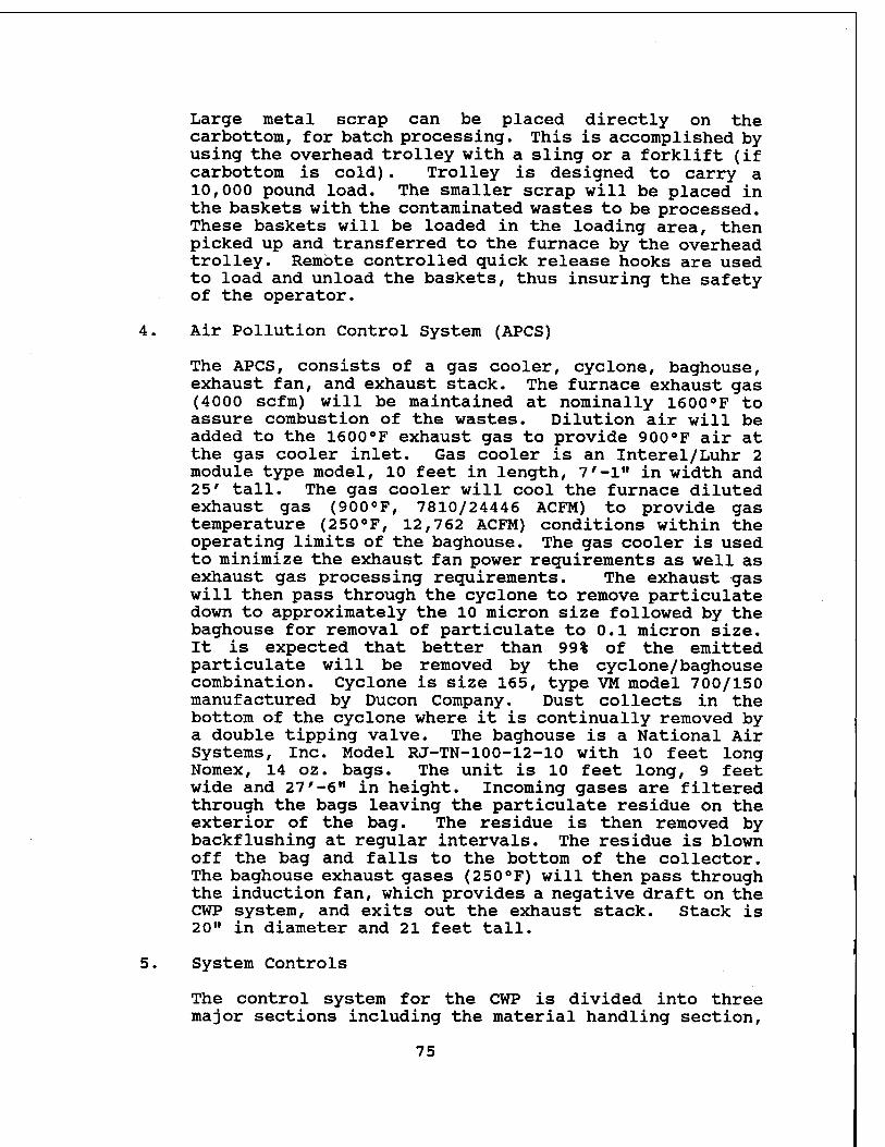
Large metal scrap can be placed directly on the carbottom, for batch processing. This is accomplished by using the overhead trolley with a sling or a forklift (if carbottom is cold). Trolley is designed to carry a 10,000 pound load. The smaller scrap will be placed in the baskets with the contaminated wastes to be processed. These baskets will be loaded in the loading area, then picked up and transferred to the furnace by the overhead trolley. Remote controlled quick release hooks are used to load and unload the baskets, thus insuring the safety of the operator.
4. Air Pollution Control System (APCS)
The APCS, consists of a gas cooler, cyclone, baghouse, exhaust fan, and exhaust stack. The furnace exhaust gas (4000 scfm) will be maintained at nominally 1600°F to assure combustion of the wastes. Dilution air will be added to the 1600°F exhaust gas to provide 900°F air at the gas cooler inlet. Gas cooler is an Interel/Luhr 2 module type model, 10 feet in length, 7'-l" in width and 25' tall. The gas cooler will cool the furnace diluted exhaust gas (900°F, 7810/24446 ACFM) to provide gas temperature (250°F, 12,762 ACFM) conditions within the operating limits of the baghouse. The gas cooler is used to minimize the exhaust fan power requirements as well as exhaust gas processing requirements. The exhaust gas will then pass through the cyclone to remove particulate down to approximately the 10 micron size followed by the baghouse for removal of particulate to 0.1 micron size. It is expected that better than 99% of the emitted particulate will be removed by the cyclone/baghouse combination. Cyclone is size 165, type VM model 700/150 manufactured by Ducon Company. Dust collects in the bottom of the cyclone where it is continually removed by a double tipping valve. The baghouse is a National Air Systems, Inc. Model RJ-TN-100-12-10 with 10 feet long Nomex, 14 oz. bags. The unit is 10 feet long, 9 feet wide and 27'-6" in height. Incoming gases are filtered through the bags leaving the particulate residue on the exterior of the bag. The residue is then removed by backflushing at regular intervals. The residue is blown off the bag and falls to the bottom of the collector. The baghouse exhaust gases (250°F) will then pass through the induction fan, which provides a negative draft on the CWP system, and exits out the exhaust stack. Stack is 20" in diameter and 21 feet tall.
5. System Controls
The control system for the CWP is divided into three major sections including the material handling section,
75
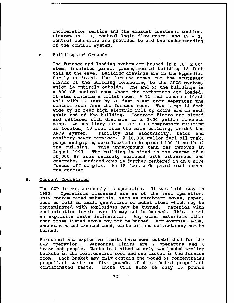
incineration section and the exhaust treatment section. Figures IV - 1, control logic flow chart, and IV - 2, control schematic are provided to aid the understanding of the control system.
6. Building and Grounds
The furnace and loading system are housed in a 30' x 80' steel insulated panel, preengineered building 18 feet tall at the eave. Building drawings are in the Appendix. Partly enclosed, the furnace comes out the southeast corner of the building connecting to the APCS system, which is entirely outside. One end of the buildings is a 800 SF control room where the carbottoms are loaded. It also contains a toilet room. A 12 inch concrete blast wall with 12 feet by 20 feet blast door separates the control room from the furnace room. Two large 14 feet wide by 12 feet high electric roll-up doors are on each gable end of the building. Concrete floors are sloped and guttered with drainage to a 1400 gallon concrete sump. An auxiliary 10' X 20' X 10 compressor building is located, 40 feet from the main building, amidst the APCS system. Facility has electricity, water and sanitary sewer services. A 10,000 gallon fuel oil tank, pumps and piping were located underground 100 ft north of the building. This underground tank was removed in August 1993. The building is sited in the center of a 50,000 SF area entirely surfaced with bituminous and concrete. Surfaced area is further centered in an 8 acre fenced off complex. An 18 foot wide paved road serves the complex.
B. Current Operations
The CWP is not currently in operation. It was laid away in 1992. Operations discussed are as of the last operation. Only contaminated materials, such as cardboard boxes, paper, wood as well as small guantities of metal items which may be contaminated with explosives may be burned. Material with contamination levels over 1% may not be burned. This is not an explosive waste incinerator. Any other materials other than those listed above may not be burned. For example, PCBs, uncontaminated treated wood, waste oil and solvents may not be burned.
Personnel and explosive limits have been established for the CWP operation. Personnel limits are 2 operators and 4 transient people. Waste is limited to only two loaded trolley baskets in the load/control room and one basket in the furnace room. Each basket may only contain one pound of concentrated propellant waste or five pounds of distributed propellant contaminated waste. There will also be only 15 pounds
76
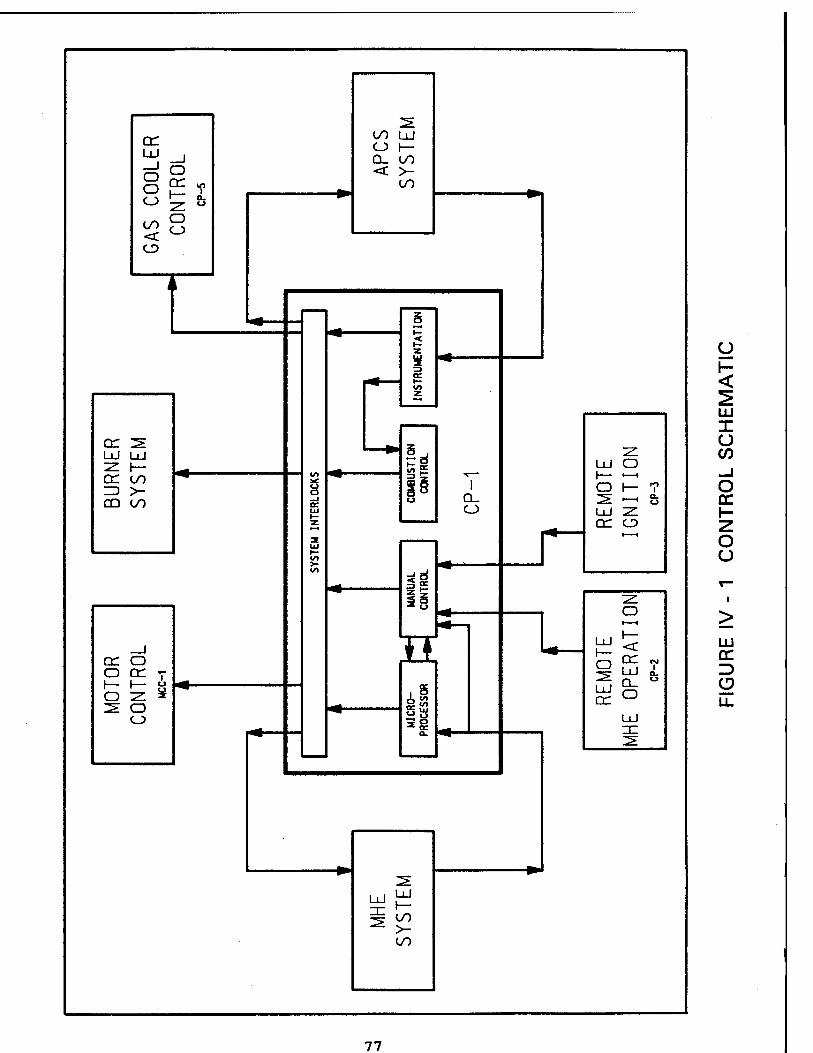
er
00 o
00 Lü O H- Q_ 00 < >-
00
er ^ Lü Lü ^ h- er oo =) >- co oo
er o o er V i— »— Ö
S O O
Q_ O
n 18
r z.
Lü o h- ■—i
O i— 1 ^ ►—i Q-
ü LÜ -z. er CD
u
LU I u
o er
O u
y5 ö vc
er *-*
er ™ i
LU
ID a
oo >- 00
77
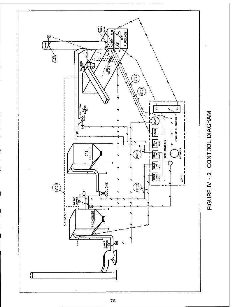
< er
< Q _J O cc \- z o u CM
LU CC D C2 LL
78
explosives in the sump. A maximum quantity of approximately 500 pounds of loosely piled wood or paper can be burned in one basket.
Operation of the CWP will first require a start-up, and then operation will be automatically or manually remote controlled from the central control panel. Once a flame has been established in the furnace, the waste materials can be fed to the cooling area of the furnace room, and into the furnace via the trolley hoist and carbottom.
The CWP can be operated as a batch (automatic or manual system) or flash (manual only system) for large size materials that cannot be placed in a basket, and for which a continuous furnace flame is applied. See Figure IV - 3, Process Flow Diagram.
1. Batch System
With the flame established in the furnace, contaminated waste is placed in the basket located in the loading area of the control room. By operating the central control panel, the trolley will pick up the selected basket, transfer it through the blast wall opening and deposit it on the carbottom. The car bottom will enter the furnace, and after burning has been completed (approximately l%-2 hrs) will exit the furnace. The trolley will then pick up the basket from the carbottom and place it on a designated location for cooling. The trolley will then return to the loading room and pick up another basket, that was loaded with contaminated waste while the preceding load was being burned, and repeat the cycle. When all baskets in the cooling room have cooled, and the furnace and related pollution control systems have been shut down and cooled, the residual scrap metal will be removed and collected separately before each basket is reloaded. The baskets and carbottom will be cleaned at least once each week or sooner, if conditions require more frequent cleaning.
2. Flash (Manual) System
Contaminated items are loaded directly into the basket on the carbottom, or carbottom itself and placed into the furnace before the furnace burns on high flame continuously for a prescribed time. The car bottom is then removed from the furnace and cooled and cleaned of residual material. The trolley hoist is not used for this mode of operation.
79
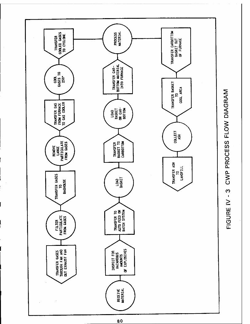
2
■4. uc ^
</> LU (/> •< UJ (9 </> COO ui l— a: u. CD V) •< z at
ac _ •— ui O u. u. i— o in z z ■«* «t _»
o z z •<
V) A u. < z 1— u «t </> UJ
u. X
=3
o X z a: Is J
< oc
<
(/) (/) tu U O cc Q.
u CO
LU
D
u_
80
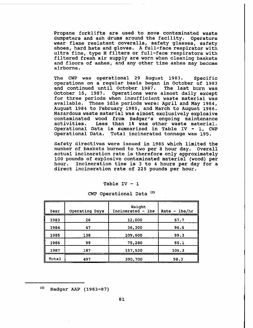
Propane forklifts are used to move contaminated waste dumpsters and ash drums around the facility. Operators wear flame resistant coveralls, safety glasses, safety shoes, hard hats and gloves. A full-face respirator with ultra fine, type H filters or full-face respirators with filtered fresh air supply are worn when cleaning baskets and floors of ashes, and any other time ashes may become airborne.
The CWP was operational 29 August 1983. Specific operations on a regular basis began in October of 1983 and continued until October 1987. The last burn was October 15, 1987. Operations were almost daily except for three periods when insufficient waste material was available. These idle periods were: April and May 1984, August 1984 to February 1985, and March to August 1986. Hazardous waste material was almost exclusively explosive contaminated wood from Badger's ongoing maintenance activities. Less than 1% was other waste material. Operational Data is summarized in Table IV - 1, CWP Operational Data. Total incinerated tonnage was 195.
Safety directives were issued in 1985 which limited the number of baskets burned to two per 8 hour day. Overall actual incineration rate is therefore only approximately 100 pounds of explosive contaminated material (wood) per hour. Incineration time is 3 to 4 hours per day for a direct incineration rate of 225 pounds per hour.
Table IV - 1
CWP Operational Data 133
Year Operating Days Weight
Incinerated - lbs Rate - lbs/hr
1983 26 12,000 57.7
1984 47 36,300 96.5
1985 138 109,600 99.3
1986 99 75,280 95.1
1987 187 157,520 105.3
Total 497 390,700 98.3
133 Badger AAP (1983-87)
81
C. Hazardous Wastes To Be Incinerated
The explosive wastes to be disposed of are generated within the Badger AAP boundaries, primarily from the manufacture of propellants. The quantity and type generated will vary month to month. Currently Badger is in standby status and small amounts of waste are being generated from ongoing activities such as maintenance, propellant storage, and research projects.
In the event of surge production, when propellant manufacture will be undertaken, a larger quantity of reactive wastes from the production lines will be generated. The estimated quantity is up to 3,600 pounds per day of wastes at maximum proposed production rates under this scenario.
1. Waste Generation
Badger AAP produces single base and double base propellants and has production facilities for nitrocellulose and nitroglycerine. There is no production facility for nitroquanidine at this location, but triple base propellant could be produced if nitroguanidine was brought in from another production plant.
The wastes generated at Badger AAP include off- specification and potentially unstable propellant and the wastes generated during the manufacturing of these propellants that cannot be recycled. Contaminated reactive components of propellants such as unusable nitrocellulose, nitroglycerine, and chemical mixtures containing these bases are also generated. Other sources of reactive wastes are laboratory testing of propellants, and research and development projects involving propellant production and investigations of environmental controls for that production. Routine maintenance, cleaning and demolition activities also discover reactive wastes that must be treated.
The propellants stored in the magazines at Badger AAP are reviewed periodically. These materials are produced at the installation. When declared off-specification from testing or exceeded shelf life, or are otherwise determined to be unusable, these materials are classified as wastes. Procedures to destroy these wastes are then initiated.
The classification of the materials as waste is made in accordance with military specifications, historical data and ordnance publications. Specific chemical propellant formulations known or expected to be produced or stored
82
at Badger AAP are provided in Tables IV - 2, Explosive & Propellant Chemical Formulations.
2. Waste Characteristics
Explosives are substances or mixtures capable by chemical reaction of producing gas at high temperature and pressure. Explosives can include high explosives, low explosives, propellants, igniters, primer, initiating and
pyrotechnic compositions. For explosives, a fast reaction produces a very high pressure shock in the surrounding medium capable of causing significant disruption or damage to that medium.
In propellants, a slower reaction produces lower pressure over a longer period of time. This lower sustained pressure is used to propel objects or to power auxiliary devices. Propellants can be distinguished from high explosives by the chemical rate of reaction. Propellants characteristically react (burn) at a rate that is much lower than the reaction rate of explosives. It is difficult to distinguish between propellants and explosives based on chemical composition alone. Propellants are characterized by the ability to be made to burn at reproducible, controllable, and predetermined rates. This is accomplished by the addition of compounds to stabilize and/or deter combustion rates. When confined to the breech and barrel of a gun, the evolved gases produce high pressures, which provide the propulsion for the projectile. Under certain conditions, however, the propellants can be made to detonate.
Pyrotechnics evolve large amounts of heat, noise, smoke, light, or infrared radiation but much less pressure than propellants or explosives. Pyrotechnic chemical reactions are generally non-explosive, relatively slow, and self-sustaining.
Propellants can be grouped into four classes. A given propellant composition may be suitable for use in several applications.
• Single-base propellant compositions are used in cannons, small arms, and grenades. These compositions contain the propellant nitrocellulose as their chief ingredient. In addition to containing a stabilizer, they may also contain inorganic nitrates, nitro-compounds, and nonexplosive materials such as metallic salts, metals, carbohydrates, and dyes.
83
Table IV - 2
Explosive & Propellant Chemical Formulations
NAME
Nitrocellulose
Nitroglycerine
BALL POWDER« Propellant WC846 Nitrocellulose Nitroglycerine Dibutylphthalate Diphenylamine Calcium Carbonate
BALL POWDER® Propellant WC870 Nitrocellulose Nitroglycerine Dibutylphthalate Diphenylamine Calcium Carbonate Potassium Nitrate Tin Dioxide
CHEMICAL FORMULA
C12H16(ON02)406
CjHjNjO,
C12Hl6(ON02)406
C3HsN309
C^COOC.H,), (C^JjNH
CaCo,
C12H16(ON02)406
CJHJNJO,
C(SH4(COOC4H9)2
(CgHjJjNH CaCo3
KN03
SnQ2
PERCENTAGES
85% 10.8% 4.5% 1.3% .2%
81% 10.8% 6.0% 1.2% .2% .9% .9%
BALL POWDER® Propellant WC844 Nitrocellulose Nitroglycerine Dibutylphthalate Diphenylamine Calcium Carbonate
Nitroguanidine
DIGL-RP Nitrocellulose Diethylene Glycol Dinitrate Ethyl Centralite Methyldiphenyl Urea Carbon (Graphite) Magnesium Oxide
C12H16(ON02)406
CjH^O, C6H4(COOC4H9)2
(C^HJJJNH
CaCo3
CH4N402
85% 10.8%
4.5% 1.3%
.2%
JA2 Nitrocellulose Nitroglycerine Diethylene Glycol Dinitrate Methyldiphenyl Urea Carbon (Graphite) Magnesium Oxide
Cl2Kl6(Om2)<06 60 .5%-65.5% C4H805N2 35 .7%-37.7%
C6HJ)NCON(C6H5 >Cft .20%-.50% (C^hNH .30%-.75%
C .05% MgO .03%-.05%
C12H16(ON02)406 59.11% CsHj^O, 15.45% C4H80jN2 24.64%
(C^JjNH .7% C .06%
MgO .04%
84
Table IV-2 continued
Slotted Stick M31A1E Nitroguanidine 0H4N4O2 54.7% Nitroglycerine CjH^NjO, 18.0% Nitrocellulose C12H16(ON02)406 21.5% Dibutylphthalate CflA{OXXifi9)i 3.0% Ethyl Centralite CJHJ (CeHj) NCON (C6HS) Cyjj 1.5% Potassium Sulfate K2SC-4 1.25% Carbon Black .05%
N34 Rocket Propellant Nitrocellulose C12H1(!(ON02)406 50% Nitroglycerine C3H5N30 35% Diethylphthalate C^COOC.H,), 10.6% 2-Nitrodiphenylamine CeHjNHC^NOj 2% Lead Hexoate (C6H1102)3Pb 1.2% Lead Salicylate Pb(OOCC6H4OH)2.H20 1.2%
M37 Propellant Nitrocellulose C12H1(!(ON02)40(! 50% Nitroglycerine C3H5N30 36.2% 2-Nitrodiphenylamine C(SH5NHC6H4N02 1.0% Glycerol Triacetate C9H1406 9.7% Lead Salicyclate C14H10O(iPb 1.5% Lead 2-Ethylhexoate CgH1602.xPb 1.5% Candelilla Wax unknown .1%
AA2 (Mk90) Nitrocellulose C12H16(ON02)406 51% Nitroglycerine CaHjNjO 38.6% 2-Nitrodiphenylamine C6H3NHC6H4N02 2.0% Di-n-propyladipate Ci2H2204 1.6% Candelilla Wax unknown 0.1% Triacetin C3H3(OCOCH3)3 2.7% LC-12-14 4.0%
{Lead Salicylate C14H10O6Pb {Copper Salicylate C14H12CU208
Ml Propellant Nitrocellulose C12H16(ON02)406 83%-87% Dinitrotoluene C6H3CH3(N02)2 8%-12% Diphenylamine (CÄJ.NH .9%-1.2% Potassium Sulfate K2S04 •7%-1.3% Dibutylphthalate GAfCOOCjH,), 4%-6%
NACO Propellant Nitrocellulose CI2H16(ON02)406 93.5% Ethyl Centralite CA (C^) NOON (C^) Oft 1.0%-1.4% Lead Carbonate PbC03 .98%-1.2% Butyl Stearate C j YH^JCOOC^HQ 2.7%-3.3% Potassium Sulfate K2S04 .95%-1.55%
M6 Propellant Nitrocellulose C12H16(ON02)406 85%-89% j Dinitrotoluene C^CtMNOjh 8%-12% Dibutylphthalate CglMCOOC.H,,), 2%-4% Diphenylamine (CftJjNH .9%-1.2% Potassium Sulfate K2S04
85
.7%-1.3%
• Double-base propellant compositions are used in cannons, small arms, mortars, rockets, and jet propulsion units. This term generally applies to compositions containing both nitrocellulose and nitroglycerine. They can also be defined as a propellant containing nitrocellulose and liquid organic nitrate which will gelatinize nitrocellulose. Additives are frequently used in addition to a stabilizer.
• Triple-base propellant compositions are used in cannon units. This term is applied to propellants containing three explosive ingredients, with nitroguanidine as the major ingredient and the other two usually nitroglycerine and nitrocellulose.
• Composite propellants contain neither nitrocellulose nor an organic nitrate. They are usually a physical mixture of a fuel such as metallic aluminum, a binder (which is normally a synthetic rubber that is also a fuel), and an inorganic oxidizing agent such as ammonium perchlorate. Composite propellants are used primarily in rocket assemblies and chemical fuel jet propulsion units and are not normally present at Badger.
A detailed chemical breakdown of all the propellant ingredients is provided in Table IV - 2 to demonstrate a representative sample of the waste propellants. This table gives the chemical composition of each propellant that could be treated in the explosive waste incinerator.
3. Production Processes
BALL POWDER® Propellant
The BALL POWDER® Propellant is a spherical propellant ranging in grain size from 0.009 to 0.032 inches in diameter. The gravimetric density ranges from 0.950 gm/cc to 1.000 gm/cc. The nominal composition of BALL POWDER® Propellant consists of 80% nitrocellulose, 10% nitroglycerine and 10% other ingredients. The shape is spherical, or reduced to a flattened, "M&M" shaped grain. Production starts out when nitrocellulose is dissolved in ethyl acetate, stabilized with diphenylamine and any acid from nitration is neutralized with chalk. The nitrocellulose/ethyl acetate "lacquer" is dispersed into small spheres or balls by adding a protective colloid and stirring under controlled conditions. The solvent is boiled off and recovered.
86
The hardened balls have their density regulated by removing osmotically, part or all of the water they still contain. The powder is then screened into several size fractions which are individually coated with nitroglycerine and a deterrent to control the burning rate. The powder is dried, screened, coated with graphite, and finally blended with other batches.
Single Base
Single base propellants can be produced in sizes for small arms up to cannon size grains (.05 -.5 inches in diameter). The grains are rod shaped with perforated holes through the center of the grains running the entire length of the rod. For single-based propellant the nominal composition is 85% nitrocellulose, 10% dinitrotoluene, and 5% other ingredients. The shape is cylindrical with 0-19 perforations. The production process starts with 30% water wet nitrocellulose (NC) which is weighed into tubs at the NC Final Wring House. The contents are put into the material baskets at the dehydration press and alcohol is introduced under low pressure to displace the water. The excess alcohol is pressed out under high pressure leaving enough alcohol for the mixing operations. The NC is then discharged from the press in the form of cylindrical blocks. The blocks are then split in half and charged into a mixer with diethyl ether, diphenylamine, dibutylphthalate, dinitrotoluene, remix and rework powder. A macerator then provides more intensive mixing. The resulting powder is then pressed into densely consolidated, air free blocks. The blocks are put through a vertical hydraulic extrusion press to form perforated strands which are cut into precise lengths. Inspections then identify suspect material which is removed from the production stream and returned to the Mix Houses. Next, at the Solvent Recovery Houses, warm inert gas is circulated through the grains to extract a large percentage of ether and alcohol. The solvents are condensed, collected and reused. The hard propellant is pumped in a slurry by water jet streams over shaker screens into water dry tanks. The grains are then dried by blowing warmed air over the propellant beds.
Double Base Solventless
Double-base solventless propellant is produced in a very similar fashion to single-based propellant with the exception that double-base contains a nitroglycerine and single-base contains no nitroglycerine. To begin production, process water, nitrocellulose and
87
nitroglycerine with prepared chemicals are added to a pre-mix tank. After proper agitation the slurry is pumped to the Final Mix House where additional chemicals may be added. After agitation the slurry is pumped to wringers for water removal down to 30% and then it is bagged. The wet paste is air dried to about 8% for 72 hours then blended for uniformity. Ballistic modifiers are blended into the paste and then the paste is moved to the Roll Houses and weighed into smaller amounts for rolling. Blanket roll sheets are then cut and rolled into carpet rolls in preparation for extrusion. The carpet rolls are then extruded into raw grains in the 15 inch presses, then inspected prior to removal. The grains are then heated (annealed) to relieve internal stresses and stabilize physical dimensions. The raw grains are then fluoroscoped and x-rayed for lot acceptance to find hidden defects. The grains then pass through a double sawhead milling machine to be cut to exact specified length. After milling, an ethyl cellulose disc with the hole slightly larger than the major inside diameter of the grain is cemented or "inhibited" to each end of the grain. Elba solvent is used as a bonding agent. The grains are then turned in the dowel rod machine to insure uniformity and proper bonding of the spiral wrap inhibitor. Three strands of clear ethyl cellulose tape is spirally wrapped and cemented on the peripheral surface of each doweled grain to form an integrally bonded inhibitor jacket six layers thick. An inspection is made of each grain before it is sent to the coning machine for machining the "coned end" to prescribed dimensions. After final inspection, the grains are packed and stored for shipment.
N 34 Rocket is one specific solventless double-base propellant with a nominal composition of 50% nitrocellulose, 40% nitroglycerine and 10% other ingredients. The shape is cylindrical small or large rods, depending on the product being produced.
At any point during production these propellants could be declared scrap as a result of analysis. At that point the scrap propellant is either returned for rework or collected as waste for disposal. The waste will always consist of nitrocellulose and may or may not contain nitroglycerine and other ballistics material, depending on the point during production that it is scrapped and the production line it comes off from. The extruded rocket grains will be broken into chips prior to waste treatment. BALL POWDER® Propellant is not altered for waste treatment.
88
4. Changes In Propellant Formulations
The use of lead and dinitrotoluene (DNT) in propellant formulations produced at Badger AAP has been questioned, and the suggestion made that Badger AAP discontinue such production. This decision cannot be made at Badger AAP. Production requirements at Badger AAP are determined at a higher level, to meet specific requirements of the U. S. Armed Forces. These requirements are for materials that have been developed and type classified by the various military services. The lead compounds and DNT used in certain formulations are required to adjust burn rates of the propellant to meet specific ballistic performance needs in a given type of ammunition application. These specifications are set by the U. S. Armed Forces.
The U. S. Armed Forces are slowly moving away from the use of propellants containing lead and DNT, and this has been evident in the requirements set for Badger AAP under mobilization conditions. In the past, 100% of the propellant produced in the rocket area would have had lead in the formulation. The current proposed requirement from the rocket area only requires 55% of the propellants to contain lead in the formulation. The rocket manufacturing area is the only place at BAAP which uses lead in the formulation of the propellant.
Substitutes for DNT in single base formulations have been suggested. Dimethylphtalate and dibuthylphtalate have been used to replace some DNT requirements.
5. Waste Minimization
During the manufacture of propellant materials at Badger AAP there are occasions when off-specification materials are produced or materials are contaminated with dirt or other foreign materials. since propellants are also stored at Badger AAP after manufacture there are occasions when the stored propellant is no longer usable for ammunition loading due to the material being unstable or obsolete. When this occurs, Badger AAP's first approach is to follow the Army's H3Rs" directive - - Recycle, Recovery, Reutilization. Therefore initial efforts are to recycle the material back into the manufacturing process. If there is a large quantity of material, such as the rejection of a complete lot due to obsolescence, Badger AAP works with Army headquarters to find a reutilization route for the material.
89
When it is not possible to recycle or reutilize the material, it must be classified as a hazardous waste because of its reactive nature. As discussed in former paragraphs, various alternates have been investigated for disposal of this material. To date, incineration is the disposal method of choice, since the material is destroyed with minimal formation of other forms of hazardous waste. For the propellant wastes generated as part of the manufacturing process at Badger AAP, burning via incinerators is the only proven means of destruction.
Badger AAP is committed to a program for the recycling, recovery, or reutilization of as much material as possible, and thus the reduction or elimination of hazardous waste generations. The Badger AAP facility is proud of the record that was achieved during the last operation when it was possible to reduce by 75% the amount of material classified as waste from the rocket area by when equipment was put on line that allowed the material to be recycled. By process changes, it was also possible to reduce by 50% the material considered as waste from the BALL POWDER® Propellant area.
Generally, the material that cannot be used and must be classified as a waste would be material that is in- process, that has not been completely stabilized, or material that has aged and is of questionable stability. For safety and environmental reasons this material must be disposed of as soon as possible by trained personnel in a responsible manner.
6. Changes In Generations
Since Badger AAP does engage in various research projects, it is possible that additional reactive compounds or PEP items may be generated at some time in the future. If the materials required for these studies are substantially different from the compounds already in use at this installation, approval for disposal of the new materials will be requested.
If the process or operation generating the hazardous waste changes, Badger AAP will submit the new operation procedures which will contain sampling and analysis plans to ensure the waste analysis is up to date.
Badger AAP does not receive shipments of hazardous waste from off-site and therefore requirements for inspections of waste shipments received from off-site do not apply.
90
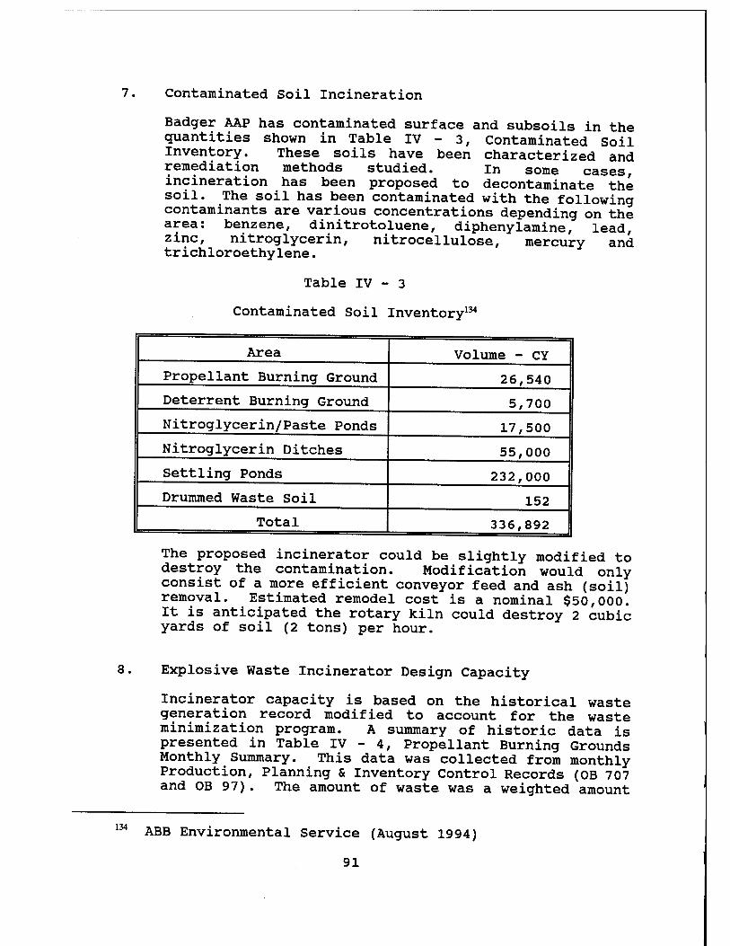
7. Contaminated Soil Incineration
Badger AAP has contaminated surface and subsoils in the quantities shown in Table IV - 3, Contaminated Soil Inventory. These soils have been characterized and remediation methods studied. in some cases incineration has been proposed to decontaminate the soil. The soil has been contaminated with the following contaminants are various concentrations depending on the area: benzene, dinitrotoluene, diphenylamine, lead, zinc, nitroglycerin, nitrocellulose, mercury and trichloroethylene.
Table IV - 3
Contaminated Soil Inventory134
Area Volume - CY
Propellant Burning Ground 26,540
Deterrent Burning Ground 5,700
Nitroglycerin/Paste Ponds 17,500
Nitroglycerin Ditches 55,000
Settling Ponds 232,000
Drummed Waste Soil 152
Total 336,892
The proposed incinerator could be slightly modified to destroy the contamination. Modification would only consist of a more efficient conveyor feed and ash (soil) removal. Estimated remodel cost is a nominal $50,000. It is anticipated the rotary kiln could destroy 2 cubic yards of soil (2 tons) per hour.
8. Explosive Waste Incinerator Design Capacity
Incinerator capacity is based on the historical waste generation record modified to account for the waste minimization program. A summary of historic data is presented in Table IV - 4, Propellant Burning Grounds Monthly Summary. This data was collected from monthly Production, Planning & Inventory Control Records (OB 707 and OB 97). The amount of waste was a weighted amount
134 ABB Environmental Service (August 1994)
91
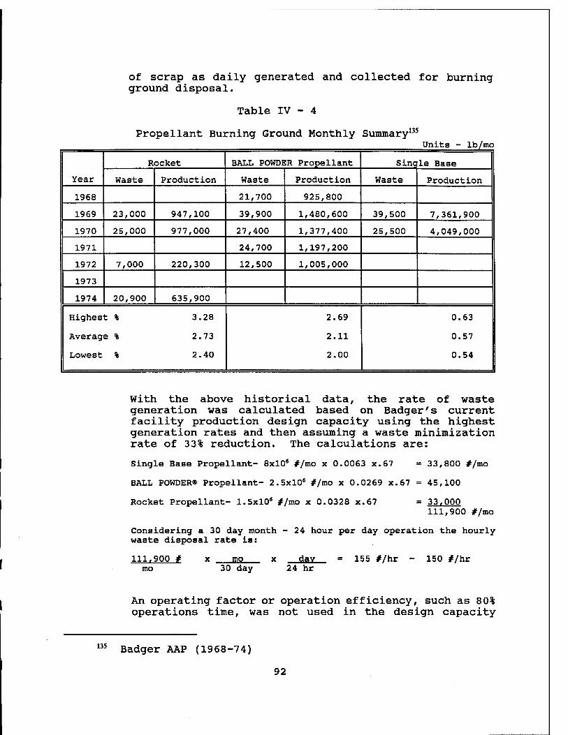
of scrap as daily generated and collected for burning ground disposal.
Table IV - 4
Propellant Burning Ground Monthly Summary135
Units - lb/mo
Year
Rocket BALL POWDER Propellant Single Base
Waste Production Waste Production Waste Production
1968 21,700 925,800
1969 23,000 947,100 39,900 1,480,600 39,500 7,361,900
1970 25,000 977,000 27,400 1,377,400 25,500 4,049,000
1971 24,700 1,197,200
1972 7,000 220,300 12,500 1,005,000
1973
1974 20,900 635,900
Highest % 3.28
Average % 2.73
Lowest % 2.40
2.69
2.11
2.00
0.63
0.57
0.54
With the above historical data, the rate of waste generation was calculated based on Badger's current facility production design capacity using the highest generation rates and then assuming a waste minimization rate of 33% reduction. The calculations are:
Single Base Propellant- 8x10* #/mo x 0.0063 x.67 = 33,800 #/mo
BALL POWDER® Propellant- 2.5xl06 #/mo x 0.0269 x.67 = 45,100
Rocket Propellant- 1.5x10* #/mo x 0.0328 x.67 = 33,000 111,900 #/mo
Considering a 30 day month - 24 hour per day operation the hourly waste disposal rate is:
111.900 # mo
mo 30 day
day 24 hr
= 155 #/hr - 150 #/hr
An operating factor or operation efficiency, such as 80% operations time, was not used in the design capacity
135 Badger AAP (1968-74)
92
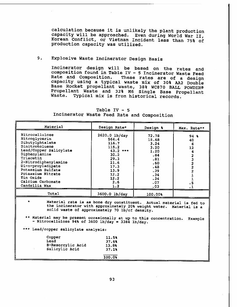
calculation because it is unlikely the plant production capacity will be approached. Even during World War II, Korean Conflict, or Vietnam Incident less than 75% of production capacity was utilized.
9. Explosive Waste Incinerator Design Basis
Incinerator design will be based on the rates and composition found in Table IV - 5 Incinerator Waste Feed Rate and Composition. These rates are of a design capacity using a typical waste mix of 30% AA2 Double Base Rocket propellant waste, 38% WC870 BALL POWDER® Propellant Waste and 32% M6 Single Base Propellant Waste. Typical mix is from historical records.
Table IV - 5 Incinerator Waste Feed Rate and Composition
Material Design Rate* Design % Max. Rate**
Nitrocellulose Nitroglycerin Dibutylphtalate Dinitrotoluene Lead/Copper Salicylate Diphenylamine Triacetin 2-Nitrodiphenylamine Di-n-proyladipate Potassium Sulfate Potassium Nitrate Tin Oxide Calcium Carbonate Candellia Wax
2620.0 lb/day 564.4 116.7 115.2 43.2 *** 30.2 29.3 21.6 17.3 13.9 12.2 12.2 2.6 1.2
72.78 15.68 3.24 3.20 1.20 .84 .81 .60 .48 .39 .34 .34 .07 .03
94 % 40 6
12 4 2 3 2 2 2 1 1
.5
.1
Total 3600.0 lb/day 100.00%
* Material rate is as bone dry constituent. Actual material is fed to the incinerator with approximately 20% weight water. Material is a solid waste of approximately 70 lb/cf density.
** Material may be present occasionally at up to this concentration. Example - Nitrocellulose 94% of 3600 lb/day = 3384 lb/day.
*** Lead/copper salicylate analysis:
Copper 11.5% Lead 37.6% B-Resorcylic Acid 13.8% Salicylic Acid 37.1%
100.0%
93
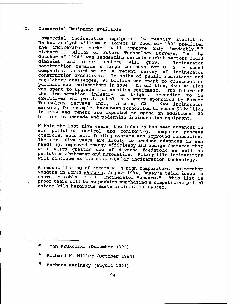
D. Commercial Equipment Available
Commercial incineration equipment is readily available. Market analyst William T. Lorenz in December 1993 predicted the incinerator market will improve only "modestly."136
Richard K. Miller of Future Technology Surveys, Inc. ' by October of 1994137 was suggesting certain market sectors would diminish and other sectors will grow. Incinerator construction remains a large business for U. S. - based companies, according to a recent survey of incinerator construction executives. In spite of public resistance and regulatory challenges, $2 billion was spent to construct or purchase new incinerators in 1994. In addition, $500 million was spent to upgrade incineration equipment. The future of the incineration industry is bright, according to 15 executives who participated in a study sponsored by Future Technology Surveys Inc., Lilburn, GA. New incinerator markets, for example, have been forecasted to reach $3 billion in 1999 and owners are expected to spend an additional $2 billion to upgrade and modernize incineration equipment.
Within the last five years, the industry has seen advances in air pollution control and monitoring, computer process controls, automatic feeding systems and improved combustion. The next five years are likely to produce advances in ash handling, improved energy efficiency and design features that will allow greater use of diverse feedstock as well as pollution abatement and automation. Rotary kiln incinerators will continue as the most popular incineration technology.
A recent listing of rotary kiln high temperature incinerator vendors in World Wasted. August 1994, Buyer's Guide issue is shown in Table IV - 6, Incinerator Vendors.138 This list is proof there will be no problem purchasing a competitive priced rotary kiln hazardous waste incinerator system.
136 John Krukowski (December 1993)
137 Richard K. Miller (October 1994)
138 Barbara Katinsky (August 1994)
94
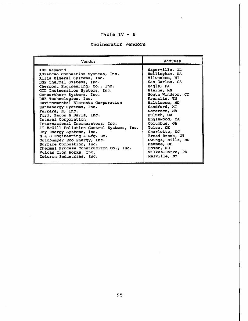
Table IV - 6
Incinerator Vendors
Vendor Address
ABB Raymond Naperville, IL Advanced Combustion Systems, Inc. Bellingham, WA Allis Mineral Systems, Inc. Milwaukee, WI BSP Thermal Systems, Inc. San Carlos, CA Chermont Engineering, Co., Inc. Eagle, PA CIL Incineration Systems, Inc. Blaine, MN Consertherm Systems, Inc. South Windsor, CT DRE Technologies, Inc. Franklin, TN Environmental Elements Corporation Baltimore, MD Euthenergy Systems, Inc. Sandford, MI Ferrara, N, Inc. Somerset, MA Ford, Bacon & Davis, Inc. Duluth, GA Interel Corporation Englewood, CA International Incinerators, Inc. Columbus, GA IT-McGill Pollution Control Systems, Inc. Tulsa, OK Joy Energy Systems, Inc. Charlotte, NC M & S Engineering & Mfg. Co. Broad Brook, CT Outobumper Eco Energy, Inc. Owings, Mills, MD Surface Combustion, Inc. Maumee, OH Thermal Process Construciton Co., Inc. Dover, NJ Vulcan Iron Works, Inc. Wilkes-Barre, PA Zelcron Industries, Inc. Melville, NY
95
V. PROPOSED INCINERATOR FACILITY
General Proposed Plan
Badger's existing Contaminated Waste Processor (CWP) can be used to also dispose of waste energetic compounds through the addition of a rotary kiln furnace. The literature search and review of existing equipment found rotary kiln furnaces are the best choice of an energetic disposal furnace and can be installed in the existing CWP facility with minimal effort.
1. Siting
The proposed explosive waste incinerator will be located at the existing CWP facility as sited on Figure V - 1, Safety Site Plan. It is properly sited in accord with AMC-R 385- 100, Safety Manual.139 This plan is similar to the Safety Site Plan of 1978 except there is only one incinerator.1*1
Although most of the energetic waste material is waste propellants with a hazard class of 1.3 (mass-fire) there could be a small quantity of hazard class 1.1 (mass- detonating) energetic waste present. When it is present, all the energetic material must be classified as 1.1 (ie. nitroglycerin) . The existing CWP is 430 feet from the closest inhabited building, Building 420-7, Waste Water Treatment Plant. This distance will allow a quantity of almost 300,000 pounds of class 1.3 material and up to 500 pounds of class 1.1 material to be within the CWP structure. Quantity limits will be set at four hours of disposal capability or 600 pounds of class 1.3. But when class 1.1 material is present, the quantity limit will be lowered to 100 pounds. Most of the energetic waste material will be in the control room awaiting a sorting and loading into 5 pound increments. These increments will be conveyed through the firewall into the rotary kiln furnace at the rate of one 5 pound increment every 2 minutes. No energetic material will be stored at the incineration site. Waste will be periodically collected from the generation sites, brought to the incinerator and quickly disposed.
2. Military Guidance
Research as reported in paragraphs II and III indicate a rotary kiln furnace with associated air pollution abatement is the only proven mature method to dispose of energetic waste. Open burning/ open detonations are not allowed.
139
140
AMC-R 385-100 (1994)
Department of the Army Letter (SARBA-SE, 29 Dec 1976)
96
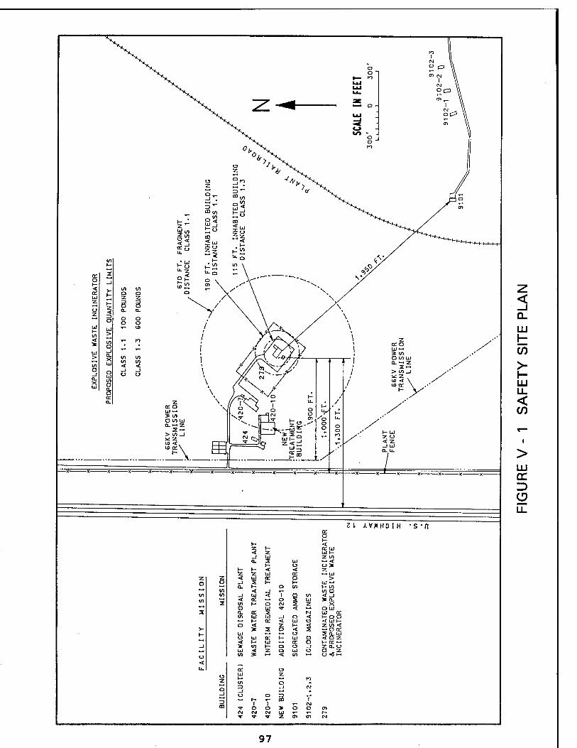
< _l Q_
LU
05 >- h- UJ u_ < if)
LU CC D CD
97
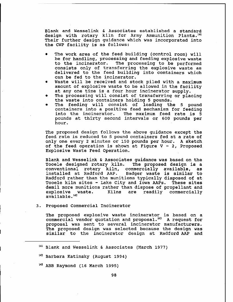
Blank and Wesselink & Associates established a standard design with rotary kiln for Army Ammunition Plants.141
Their further design guidance which was incorporated into the CWP facility is as follows:
• The work area of the feed building (control room) will be for handling, processing and feeding explosive waste to the incinerator. The processing to be performed consists only of transferring the explosive waste as delivered to the feed building into containers which can be fed to the incinerator.
• Waste will be received and stock piled with a maximum amount of explosive waste to be allowed in the facility at any one time is a four hour incinerator supply.
• The processing will consist of transferring or placing the waste into containers holding 5 pounds.
• The feeding will consist of loading the 5 pound containers into a positive feed mechanism for feeding into the incinerator. The maximum feed rate is 5 pounds at thirty second intervals or 600 pounds per hour.
The proposed design follows the above guidance except the feed rate is reduced to 5 pound containers fed at a rate of only one every 2 minutes or 150 pounds per hour. A sketch of the feed operation is shown at Figure V - 2, Proposed Explosive Waste Feed Operation.
Blank and Wesselink & Associates guidance was based on the Tooele designed rotary kiln. The proposed design is a conventional rotary kiln, commercially available, as installed at Radford AAP. Badger waste is similar to Radford rather than the munitions typically disposed of at Tooele kiln sites - Lake City and Iowa AAPs. These sites demil more munitions rather than dispose of propellant and explosive waste. Kilns are readily commercially available.142
3. Proposed Commercial Incinerator
The proposed explosive waste incinerator is based on a commercial vendor quotation and proposal.143 A request for proposal was sent to several incinerator manufacturers. The proposed design was selected because the design was similar to the incinerator design at Radford AAP and
141
142
143
Blank and Wesselink & Associates (March 1977)
Barbara Katinsky (August 1994)
ABB Raymond (16 March 1995)
98
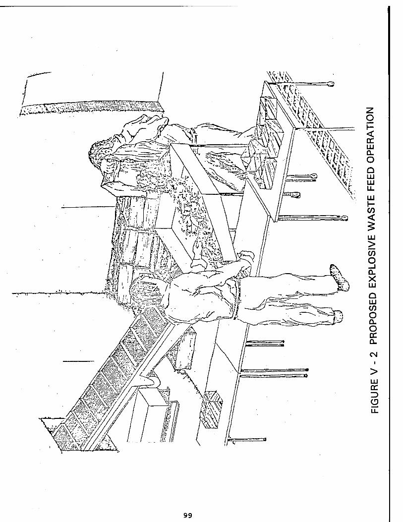
g < DC LU Q. o Q 1X1 LU LL.
LU \- C/) <
LU >
O —i Q. X LU
Q LU (/) O Q_ o DC Q.
CM
>
LU DC
O LL
99
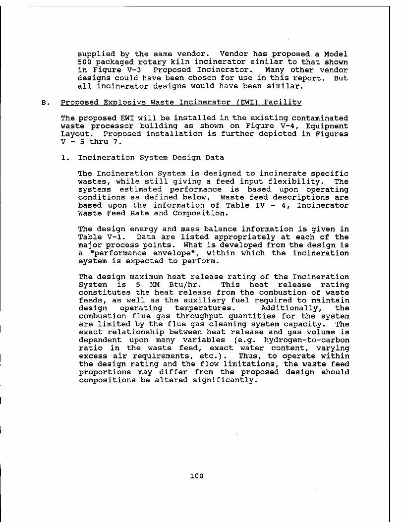
supplied by the same vendor. Vendor has proposed a Model 500 packaged rotary kiln incinerator similar to that shown in Figure V-3 Proposed Incinerator. Many other vendor designs could have been chosen for use in this report. But all incinerator designs would have been similar.
B. Proposed Explosive Waste Incinerator (EWI) Facility
The proposed EWI will be installed in the existing contaminated waste processor building as shown on Figure V-4, Eguipment Layout. Proposed installation is further depicted in Figures V - 5 thru 7.
1. Incineration System Design Data
The Incineration System is designed to incinerate specific wastes, while still giving a feed input flexibility. The systems estimated performance is based upon operating conditions as defined below. Waste feed descriptions are based upon the information of Table IV - 4, Incinerator Waste Feed Rate and Composition.
The design energy and mass balance information is given in Table V-l. Data are listed appropriately at each of the major process points. What is developed from the design is a "performance envelope", within which the incineration system is expected to perform.
The design maximum heat release rating of the Incineration System is 5 MM Btu/hr. This heat release rating constitutes the heat release from the combustion of waste feeds, as well as the auxiliary fuel reguired to maintain design operating temperatures. Additionally, the combustion flue gas throughput quantities for the system are limited by the flue gas cleaning system capacity. The exact relationship between heat release and gas volume is dependent upon many variables (e.g. hydrogen-to-carbon ratio in the waste feed, exact water content, varying excess air requirements, etc.). Thus, to operate within the design rating and the flow limitations, the waste feed proportions may differ from the proposed design should compositions be altered significantly.
100
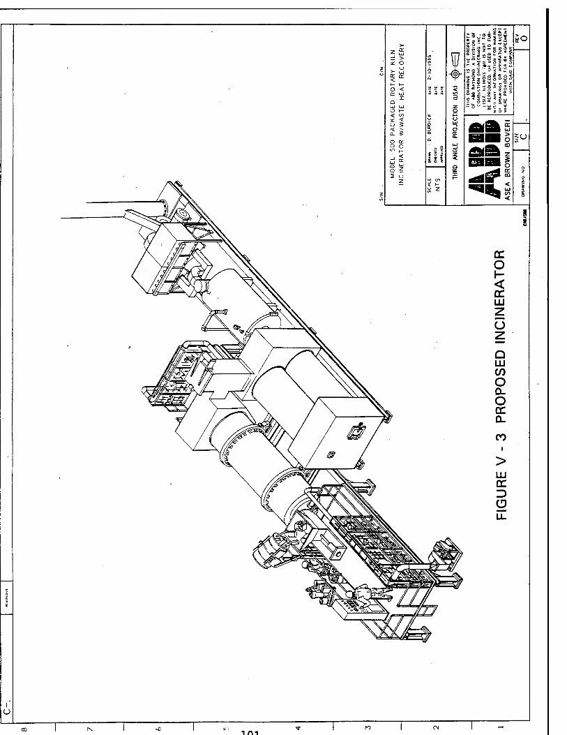
So z ^
* o in w - K £ UJ < ■- a.
-O" " Z 5 £ 3
z
o < or UJ
I o UJ UJ O i-
< «/I 3
z O
TH
IS
DR
AW
ING
I
S
OF A
BB
RA
YM
ON
D
CO
MB
US
TIO
N
EN
G
LIS
LE
. IL
LIN
OIS
/
BE
R
EP
RÜ
DO
CE
D. U
t- N
ISM
AN
Y
INF
0R
MA
1
OF
DR
AW
ING
S
OR
AP
WH
ER
E
PR
OV
IDE
D
FO
W
ITH
SA
ID
* < U Q
o AAS o cc O
a. 1 ~o 9 ° IT) ,_
ill ffifSS z id ^ 0 Z
z
i X
ESB§ o z o z <-* C/l
z in
w Z
^**\ <
/^•^ J)Aar% s
i ^-^ '**^>C.'7^v'V rpr3 K*S*>>
cc O
<
&- r\ cr LU z u z ^ *Ä/\
#8lS= Q LU
o ^\/
Jffifi\&^£\ g// //// a. O cc
%<MJ&$/ / x
/ *&> / Q_
/ @ /
CO i
>
LU CC Z) (D LL
§sgH# äN V^viwsSwjjp^SSSv
yf%\ L ' xTv^yv^äSsS SSL, X<v V^"?\ it^l _SS™~»»ff
05^^ '
7 w
f o
\>
i m
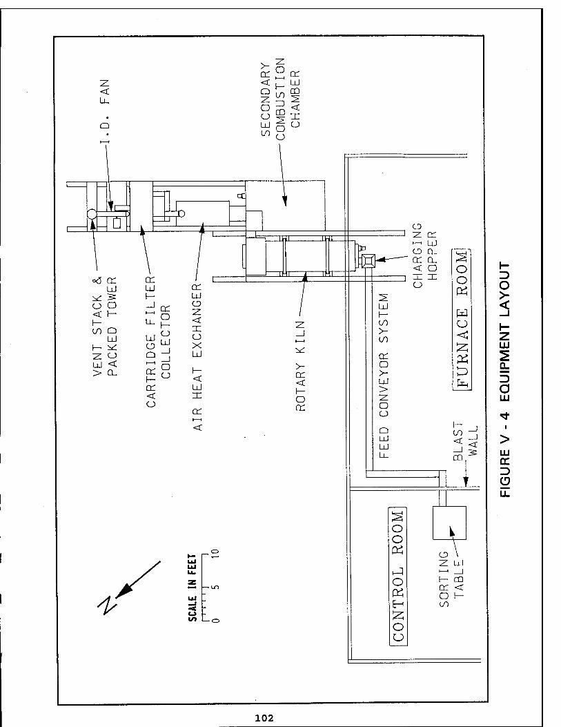
cr h! cr z
SECONDA
COMBUST
CHAMBE
< U_
• 1 1
1
I
<~- \} cC -I- CD z cr ►—' UJ
__L D
Jl ■ i 1
i:-n ii-ii
IP O Q_ cr o_ S 1
o<5 cr ÜJ
\ L Ji J < o IE IE o
O O
I—
O tr ' uj cr
1 -II i 1 -11 i i
^ ^ h- UJ 2 >- o o ^ er ^ ÜJ < < 1- ~ o 5 ' I— w _i h- 00 Q
LÜ 1— ^
^-S < z
2^ ;*■ ^
00 >- 00
1- z UJ
Z o Q — LJ -*" cr K £> fe
2 UJ < > CL
RTRI
CO
EAT
TARY o
>- LJJ
>
CL
D a < ^- o Z UJ ° cr er ^ o
CJ <* < O k-J '
UJ Ul U_ 3g
CD -^
>
UJ CC D Ü u_
T
s O i O T \
*- _ o # CD \ V UJ Z Ul
X Sf HJ |—• _J
/ = o f— CD A c — — LD cr <
+' UJ _l ■< o to — O
O \- 00
O o
102
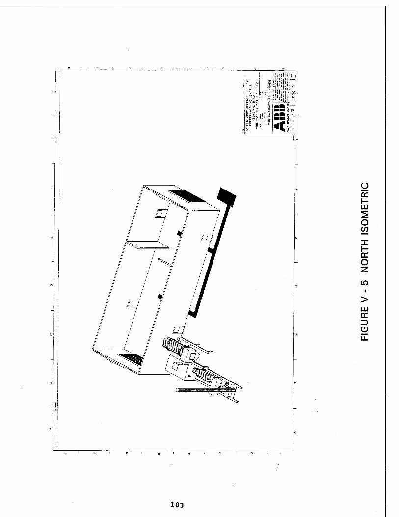
z So s _ 2
*|is Uil!
<;
u tr \- LU
o en
O
in
LU
n I «
103
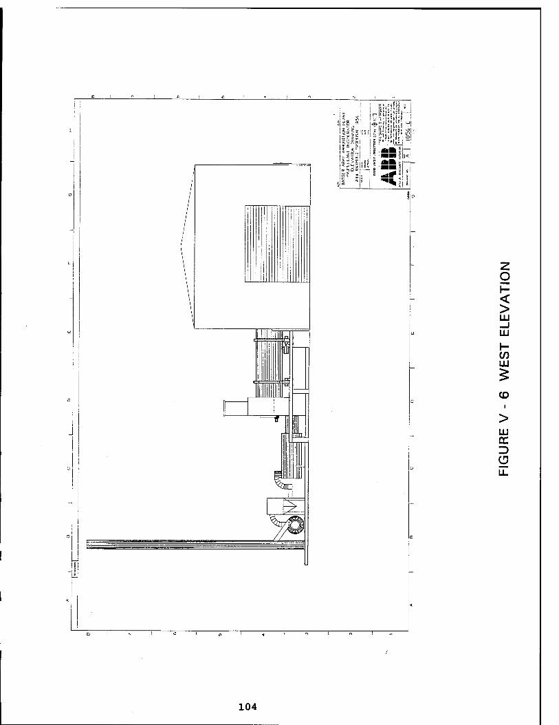
< >
_J LU
h- (/) LU
CO
LU
CO ' N I
104
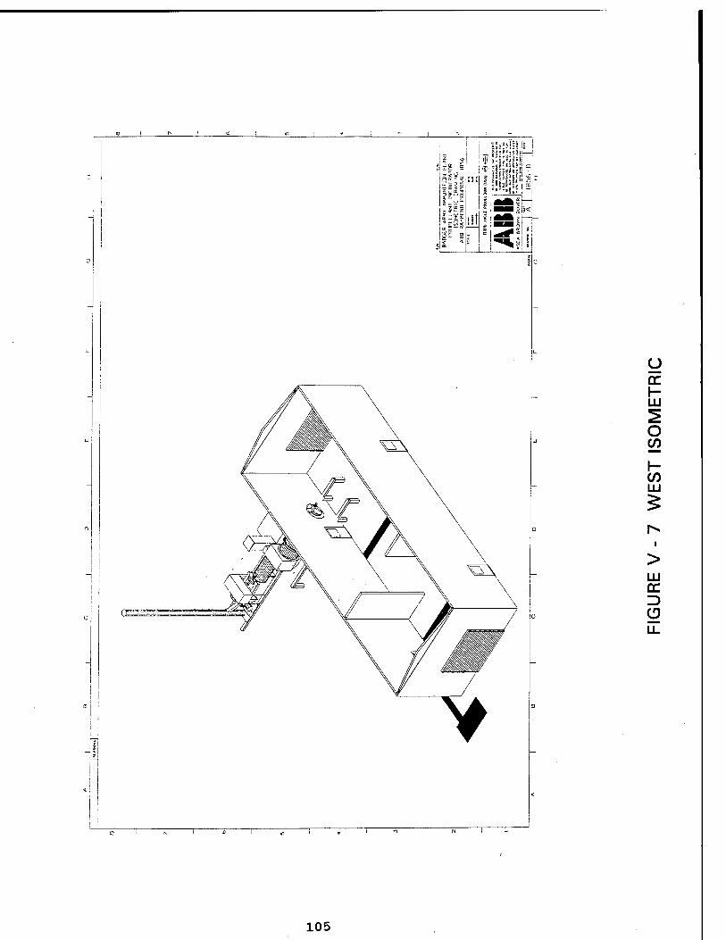
y tr UJ
O CO
CO
LU cc
105
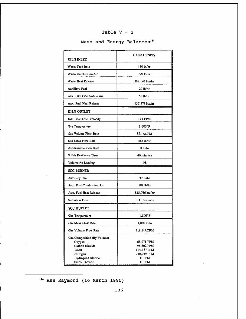
Table V - 1
Mass and Energy Balances144
KILN INLET CASE 1 UNITS
Waste Feed Rate ISO Ib/hr
Waste Combustion Air 770 lb/hr
Waste Heat Release 389,145 btu/hr
Auxiliary Fuel 20 lb/hr
Aux. Fuel Combustion Air 58 lb/hr
Aux. Fuel Heat Release 437,775 btu/hr
KILN OUTLET
Kiln Gas Outlet Velocity 123 FPM
Gas Temperature 1,600°F
Gas Volume Flow Rate 871 ACFM
Gas Mass Flow Rate 685 lb/hr
Ash/Residue Flow Rate 0 lb/hr
Solids Residence Time 40 minutes
Volumetric Loading 1%
SCC BURNER
Auxiliary Fuel 37 lb/hr
Aux. Fuel Combustion Air 588 Ib/hr
Aux. Fuel Heat Release 815,766 btu/hr
Retention Time 3.11 Seconds
SCC OUTLET
Gas Temperature 1,800°F
Gas Mass Flow Rate 1,880 lb/hr
Gas Volume Flow Rate 1,819 ACFM
Gas Composition (By Volume) Oxygen Carbon Dioxide Water Nitrogen Hydrogen Chloride Sulftir Dioxide
68,071 PPM 96,602 PPM
124,387 PPM 710,939 PPM
OPPM OPPM
144 ABB Raymond (16 March 1995)
106
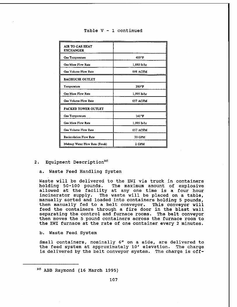
Table V - 1 continued
AIR TO GAS HEAT EXCHANGER
Gag Temperature 400°F
Gas Mass Flow Rate 1,880 lb/hr
Gas Volume Flow Rate 698 ACFM
BAGHOUSE OUTLET
Temperature 380^
Gas Mass Flow Rate 1,995 lb/hr
Gas Volume Flow Rate 657 ACFM
PACKED TOWER OUTLET
Gas Temperature 141°F
Gas Mass Flow Rate 1,995 lb/hr
Gas Volume Flow Rate 657 ACFM
Recirculation Flow Rate 30GPM
Makeup Water Flow Rate (Fresh) 2GPM
Equipment Description 145
a. Waste Feed Handling System
Waste will be delivered to the EWI via truck in containers holding 50-100 pounds. The maximum amount of explosive allowed at the facility at any one time is a four hour incinerator supply. The waste will be placed on a table, manually sorted and loaded into containers holding 5 pounds, then manually fed to a belt conveyor. This conveyor will feed the containers through a fire door in the blast wall separating the control and furnace rooms. The belt conveyor then moves the 5 pound containers across the furnace room to the EWI furnace at the rate of one container every 2 minutes.
b. Waste Feed System
Small containers, nominally 6" on a side, are delivered to the feed system at approximately 10' elevation. The charge is delivered by the belt conveyor system. The charge is off-
145 ABB Raymond (16 March 1995)
107
loaded into the charging hopper, by a pneumatic side pusher. The charge enters a hopper which aligns it with the feed chute. Two pneumatic isolation gates are provided on the feed chute. The uppermost of the two isolation gates opens and the charge falls into the charging chamber. The upper chute door closes. The charge is now isolated from both the kiln and ambient environment. The lower isolation gate opens and the charge enters the feed chute. See Figure V - 8.
The feed chute is provided to gravity feed waste from the charging chamber to the rotary kiln. Electrical interlocks are used to prevent improper sequencing of the gates and side pusher. Each complete charge cycle, including loading of material, typically requires one minute.
c. Rotary Kiln
The primary component in the solid waste incinerator is the variable speed rotary kiln. The revolving cylinder imparts a mixing action to the waste material that continually exposes new material to the combustion atmosphere and results in a more efficient burnout than most other types of incinerators. The variable speed drive results in a controllable residue residence time, thus assuring optimal combustion efficiency.
The inlet breeching and the discharge chamber are fitted to the revolving cylinder with sealing mechanisms that minimize air in leakage. The combustion air for the waste is blown into the kiln through the inlet head. The waste combustion air blower has a damper to vary the amount of excess air. For this reason, high combustion efficiency can be assured for diverse waste constituents over a wide range of operation conditions.
The end of the rotary kiln enters a discharge breeching. The purpose of this breeching is two fold; thoroughly mix the gaseous products of combustion which have been moving through the kiln under laminar flow conditions; and to disengage the large particles from the flue gas and collect them in the ash handling system. A double dump valve is provided to bottom discharge ash from the incinerator.
An auxiliary burner is provided on the kiln inlet. The primary purpose of this burner is to supply heat input (flame) to initiate/maintain the combustion of waste materials and maintain the kiln operating temperature. The burner's flame is characterized by an elongated flame pattern to provide uniform heat distribution throughout the kiln to prevent temperature deviation from design operating conditions. The burner system comes with a complete burner management and flame safety package.
108
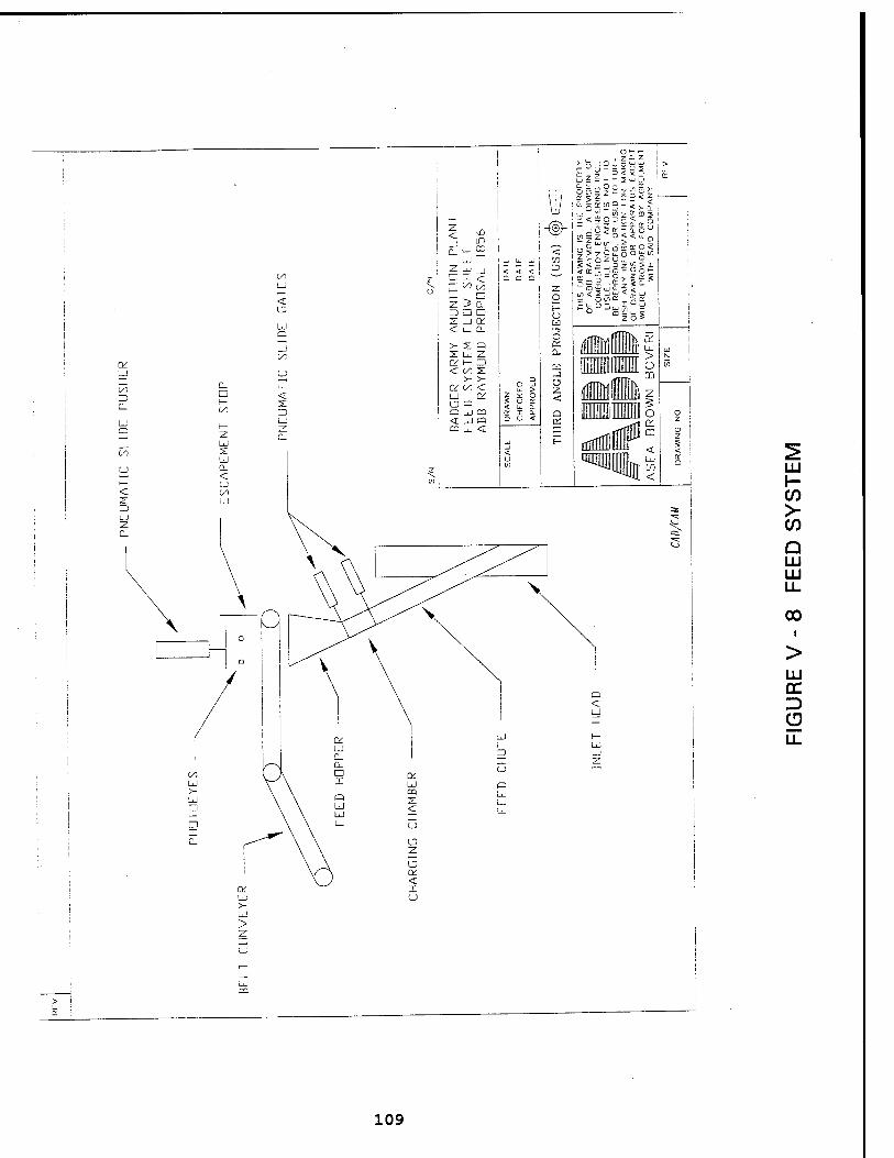
UJ
> CO
Q LU LU LL
00
LU
D
LL
109
d. Secondary Combustion System
All gaseous products of combustion from the rotary incinerator pass into the horizontal Secondary Combustion Chamber (SCC) . The purpose of the SCC is to provide a minimum of two seconds residence time for the combustion gases in an excess air environment, at normal operating temperature, with an adequate amount of mixing. Without proper mixing (turbulence), channeling of the gas flow will occur and the combustion reactions will not go to completion.
An auxiliary burner is supplied and mounted on the SCC. the purpose of this burner is to maintain the SCC chamber at the design operating temperature. This temperature must be achieved prior to the introduction of wastes anywhere in the system. The burner's flame is characterized by a relatively short, luminous, high velocity, quick, mixing flame pattern to accomplish the desired localized heat distribution. The burner system comes with a complete burner management and flame safety package.
The outlet of the SCC represents the end of the combustion reaction. Hence, it represents an ideal location for the emergency stack. The emergency stack, as its name suggests, is used only in the event of an emergency condition. Typical emergency conditions that would mandate use of the stack would be loss of electrical power, or loss of system draft.
The emergency vent stack utilizes pneumatic power to 'hold' the emergency vent stack cap closed during normal operating conditions. In the event of a pneumatic power failure, the built-in counterweight will open the cap. If the cap opens all waste feeds and burners are automatically stopped.
e. Heat Recovery/Flue Gas Cleaning Systems
An air to gas heat exchanger is provided to cool the hot flue gases indirectly to 400°F. The flue gas from the heat exchanger absorber enters a cartridge collector which is a continuous automatic filter to remove particulate from the gas by passing it through filter cartridges.
The dirty or contaminated gas enters the dust collector module through an inlet in the hopper. A baffle plate, fabricated from perforated plates with a wear-resistant back plate, distributes the gas uniformly throughout the housing and causes the heavier particulate to drop directly into the hopper. The gas then passes through the filter cartridges which retain the dust particles on the exterior surface while allowing the cleaned gas to pass through the module outlet.
110
The build-up of particulate on the cartridges causes a restriction to flow (increase in pressure drop) and periodically the cartridges are cleaned by a jet of compressed air being blown down the inside of the bags. The cartridge flexes rapidly and the particulate on the outside of the cartridge is thrown off and settles into the hopper where it is removed to disposal.
A radial blade, high pressure induced draft fan is supplied to maintain proper draft control in the incinerator system. An opposed blade over damper is modulated via an electric actuator to maintain a constant negative pressure (-0.5 W.C.) at the rotary kiln inlet.
The packed tower wet scrubber is used for removal of acid gas constituents in the flue gas. This is achieved by promoting intimate contact between the acid gases and a caustic solution introduced into the scrubber, using a high surface area packing material. Control of caustic feed is by pH level, as sensed by flow-through probes in recirculating piping. The packed tower scrubber is supplied complete with packing, valves, pumps, sprays, and controls.
A vent stack is provided for discharge of clean flue gases in the atmosphere. The stack is complete with test ports, platform, and ladder access.
f. Instrumentation and Controls
The nucleus of the proposed incineration system instrumentation and control package consists of state-of-the- art, electronic microprocessor based Programmable Logic Controller (PLC) with a personal computer (PC) software interface. This blend of hardware and software is designed to meet the proposed system requirements as well as having the capability to accommodate future changes or additions to the system.
The PLC used in the incineration system instrumentation and control package primarily serves as a loop controller, relay, timer, and counter replacement device.
The PLC accepts a full range of analog and digital inputs. The system's logic control is programmed, using a personal computer as a "loader" device. The system's personal computer and associated software provided the operator with full incineration system control and operational capability. The personal computer (PC) consists of an 80486 class computer with color monitor (CRT), engineer's keyboard, hard disk, floppy disk drive and a high speed dot matrix printer.
Ill
The PC and software provided allow the operator or engineer the ability to configure the loop controllers, primary sensing devices and final control devices into a coherent graphic representation of the system.
Multiple levels of alarm monitoring and recording. The ability to manipulate all process control parameters such as controller set points output signals, and alarm values. The ability to reconfigure system instruments and controls to accommodate changes or expansion. Trending of process variables and subseguent recording. The ability to store all loop controller and PLC information.
A continuous emissions monitoring system is supplied to monitor the gases leaving the stack.
3 . Incineration System Operation146
a. Operation Description
The rotary kiln incinerator is not an inherently difficult process to control. However, due to the nature of the wastes being processed and regulatory reguirements concerning the operation of this incinerator, it becomes especially important to operate the facility safely and efficiently, and at the same time to minimize process excursions which could cause unstable operation and subseguent process shutdowns. The process control strategies which have been designed are implemented with this objective in mind. The following is a discussion of the critical process control systems for this facility. Similarly other operating parameters must be maintained at all times (e.g. kiln draft, kiln velocity, system gas volume, etc.)
Regulation of the waste streams is based upon the swing- load/base-load control philosophy. The burners in the kiln and SCC are swing loads and the other input streams are base loads. The base loads have variable chemical and physical properties and the swing load fuels are relatively homogeneous in these properties. Base loads are set based upon operator defined setpoints. The swingloads are controlled by the appropriate control loops.
Kiln temperature control is via a PID loop linking the kiln combustion control system and exit gas temperature as measured by thermocouples mounted at the kiln exit. SCC temperature control is via a PID loop linking the SCC burner
146 ABB Raymond (16 March 1995)
112
and SCC exit gas temperature as measured by thermocouples mounted at the SCC exit.
The differential pressure across the cartridge collector is continually monitored. Compressed air is periodically pulse- injected through rows of cartridges. This cycle may be defined strictly by timer, or as the pressure drop increases across the cartridges, the pulse may be initiated. The sequencing control automatically selects specific rows for cleaning once the cycle is initiated.
The baghouse hopper rotary airlock is also controlled on a timed sequence to maintain proper level of dust in the hopper. The timing sequence may be manually adjusted to suit operating conditions. If the rotary valve fails to properly discharge material, then the hopper level indicator will activate a vibrator to dislodge ash from the side walls of the hopper.
b. System Operation
The incineration system is maintained through a series of electrical interlocks. Each interlock represents a mandatory operable condition of the various individual components and flows that must be satisfied interdependently for total system operation.
There are three basic shutdown modes for the system: normal, upset and emergency. A normal system shutdown occurs as a result of an operator initiated action, an upset system shutdown occurs as result of non-operator initiated upset condition triggering automatic waste feed and/or fuel cut-off systems, and the emergency system shutdown occurs as a result of a limited number of non-operator initiated emergency conditions.
The alarm-only levels occur as a preset point is reached, and are labeled as low or high level conditions (e.g., high kiln temperature). If the alarm condition continues to a more critical upset condition level, a second alarm set point is reached, given as low-low or high-high (e.g., kiln high-high temperature). This is a serious upset condition which initiates a controlled shutdown sequence.
In most cases, prior to a shutdown condition, the system responds with alarms allowing operators to control the situation prior to a shutdown. Automatic shutdown mechanisms assure that, if the operator does not take the required response, the system will revert to the fail-safe conditions.
113
• Normal System Shutdown
When the incineration system is in normal operation with no prevailing upset occurring, an operator-initiated action can cut off waste feed. With this action, the kiln and/or the SCC feed will be shutdown automatically by electrical interlocks. The kiln and afterburner chamber temperatures are "ramped" down, by automatic operation of the individual temperature control loops to ambient conditions. This down-ramping can be initiated by the plant operators or by an off-delay timer that allows all of the residual product in the kiln to be completely processed at proper operating temperature. Additionally, all kiln generated flue gases continue to be processed through the flue gas treatment system. Although the kiln temperature is decreasing, there is ample heat contained in the brick to maintain complete combustion of the organic residual. After the kiln and SCC have been brought down to the prescribed low temperature, the auxiliary fuel burners, fan, pumps, etc., can be shut down.
• Upset System Shutdown
The primary monitoring devices (e.g. flow transmitters, differential pressure transmitters, etc.) are designed, upon failure of operation, to default to the lower or upper limit of their monitoring parameter. Thus, this would stimulate additional upset conditions not shown on Table V - 2, Control Logic Chart and also automatically shutoff waste feed inputs. The operator would be notified through annunciator indication of the upset. All interlock points listed will be monitored either directly or indirectly through a multi-point annunciator.
The system features a capability that allows the operator to adjust system set points or controller output values to avert possible upset conditions. These features also allow the operator to correct certain upset conditions, once they have occurred, to return the system to normal operation.
• Emergency System Shutdown
The emergency shutdown procedures represent the most critical and undesirable incineration system occurrence. Therefore, every effort from a system design standpoint has been made to minimize this occurrence. The interlocks are those which will automatically initiate an emergency shutdown. These conditions directly, or indirectly, disable the normal operation of the system and, therefore, require by-pass of the system through the emergency stack.
114
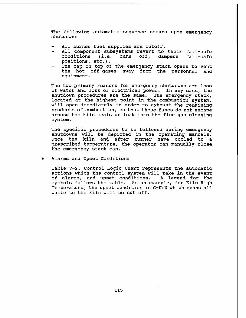
The following automatic sequence occurs upon emergency shutdown:
All burner fuel supplies are cutoff. All component subsystems revert to their fail-safe conditions (i.e. fans off, dampers fail-safe positions, etc.). The cap on top of the emergency stack opens to vent the hot off-gases away from the personnel and equipment.
The two primary reasons for emergency shutdowns are loss of water and loss of electrical power. In any case, the shutdown procedures are the same. The emergency stack, located at the highest point in the combustion system, will open immediately in order to exhaust the remaining products of combustion, so that these fumes do not escape around the kiln seals or leak into the flue gas cleaning system.
The specific procedures to be followed during emergency shutdowns will be depicted in the operating manuals. Once the kiln and after burner have cooled to a prescribed temperature, the operator can manually close the emergency stack cap.
• Alarms and Upset Conditions
Table V-2, Control Logic Chart represents the automatic actions which the control system will take in the event of alarms, and upset conditions. A legend for the symbols follows the table. As an example, for Kiln High Temperature, the upset condition is C-K:W which means all waste to the kiln will be cut off.
115
Table V - 2
Alarm, Upset, and Emergency Conditions
Control Logic Chart
Control Parameter
Kiln Low Temperature Kiln High Temperature Kiln High High Temperature Kiln Burner Flame Failure Kiln Positive Pressure Kiln Combustion Air Low Pressure Kiln Waste Combustion Air Low Pressure
Alarm
A A A A A A A
Upset Condition
C-K:W
C-K:W
C-K:W
SCC High Temperature SCC High High Temperature SCC Low Temperature SCC Burner Flame Failure SCC Waste Air Fan Failure SCC Combustion Air Low Pressure
A A A A A A
C-S:A C-W
Dust Collector Inlet High Temperature Dust Collector Inlet High High Temperature Dust Collector Inlet Low Temperature Dust Collector High Differential Pressure Primary Electrical Source Failure Primary Water Supply Failure I.D. Fan Failure Legend for Control Logic Charts
A = Alarms C = Cutoff of Input Stream
For Cutoff Condition
K = Kiln S = Secondary Combustion Chamber W = Waste A = All Waste and Fuels
For Example:
C-A = All Waste Feeds and Fuels C-W = All Waste Feeds C-K:W = All Waste Feeds to Kiln C-K:A = All Waste Feed and Fuels to Kiln C-S:W = All Waste Feeds to SCC C-S:A = All Waste Feeds and Fuels to SCC
A A A A A A A
C-A
C-A C-A C-A
116
4. Equipment Details147
Within this section is a detailed description of equipment. A catalog cut of proposed equipment is shown at Figure V - 9 & 10.
a. Waste Feed Handling System
The system consists of a steel grounded work table and three belt conveyors. A blast wall fire door is also part of the system. Total belt conveyor length is about 50 feet.
b. Waste Feed System
Container Charging System
The system consists of a customer supplied belt conveyor which can accommodate the queuing of containers for the feed system. The conveyor has a photoeye and escapement stop. The section of conveyor directly in front of the side pusher provides for weighing of each load prior to entering the charging chamber. Overweight containers will be rejected. A side pusher pushes the drum off and into the charging chamber.
The charging carbon steel chamber consists of two knife gates, and is integral to the feed chute.
Feed Chute
Nominally the feed chute is at a 65° angle with respect to horizontal. The portion of the chute which projects into the inlet head is surrounded with a liquid cooled jacket. Temperature and pressure measuring devices are provided at the inlet and outlet. A flow monitoring device is provided at the outlet of the cooling system. The upper chute is constructed of carbon steel and the lower chute of 316 S.S.
Kiln Auxiliary Clean Fuel Burner
Burner is mounted on the inlet head burning natural gas or No. 2 fuel oil with a maximum gross heat output of 1,000,000 Btu/hr. The burner is by North American Manufacturing (or equal) and features the following:
• No wiretrays. Galvanized steel conduit w/appropriate length flexible connections to instruments.
• Channel construction of frame
147 ABB Raymond (16 March 1995)
117
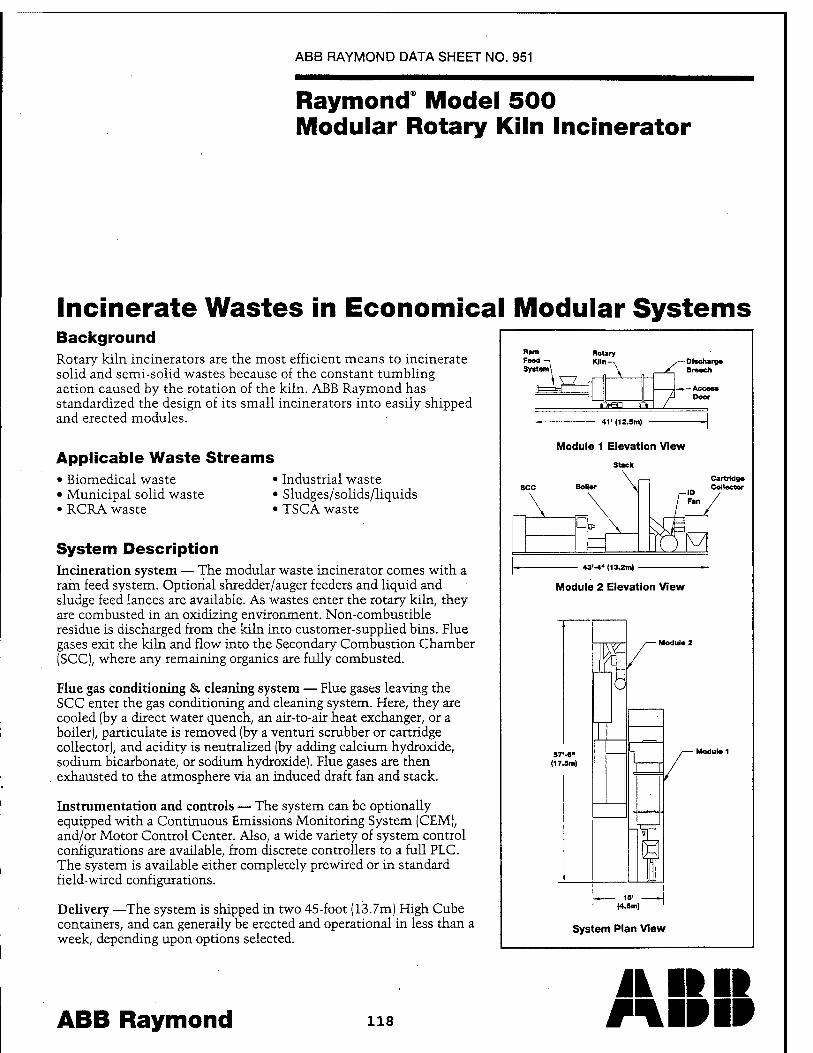
ABB RAYMOND DATA SHEET NO. 951
Raymond" Model 500 Modular Rotary Kiln Incinerator
Incinerate Wastes in Economical Modular Systems Background Rotary kiln incinerators are the most efficient means to incinerate solid and semi-solid wastes because of the constant tumbling action caused by the rotation of the kiln. ABB Raymond has standardized the design of its small incinerators into easily shipped and erected modules.
Applicable Waste Streams • Biomedical waste < • Municipal solid waste < • RCRA waste
• Industrial waste • Sludges/solids/liquids • TSCA waste
System Description Incineration system — The modular waste incinerator comes with a ram feed system. Optional shredder/auger feeders and liquid and sludge feed lances are available. As wastes enter the rotary kiln, they are combusted in an oxidizing environment. Non-combustible residue is discharged from the kiln into customer-supplied bins. Flue gases exit the kiln and flow into the Secondary Combustion Chamber (SCC), where any remaining organics are fully combusted.
Flue gas conditioning & cleaning system — Flue gases leaving the SCC enter the gas conditioning and cleaning system. Here, they are cooled (by a direct water quench, an air-to-air heat exchanger, or a boiler), particulate is removed (by a venturi scrubber or cartridge collector), and acidity is neutralized (by adding calcium hydroxide, sodium bicarbonate, or sodium hydroxide). Flue gases are then exhausted to the atmosphere via an induced draft fan and stack.
Instrumentation and controls — The system can be optionally equipped with a Continuous Emissions Monitoring System (CEM), and/or Motor Control Center. Also, a wide variety of system control configurations are available, from discrete controllers to a full PLC. The system is available either completely prewired or in standard field-wired configurations.
Delivery —The system is shipped in two 45-foot (13.7m) High Cube containers, and can generally be erected and operational in less than a week, depending upon options selected.
ABB Raymond 118
FM4 System
Rotary Klln- -1 win-^
"I n \
ffrea o
-Dfscharg« Breoch
-Access Door
41' (12.5m)
Module 1 Elevation View
Stack
43'-4" (13.2m)
Module 2 Elevation View
57'-«" (17.5m)
m - 15' -
(4.6m)
System Plan View
Jk IIII mpip
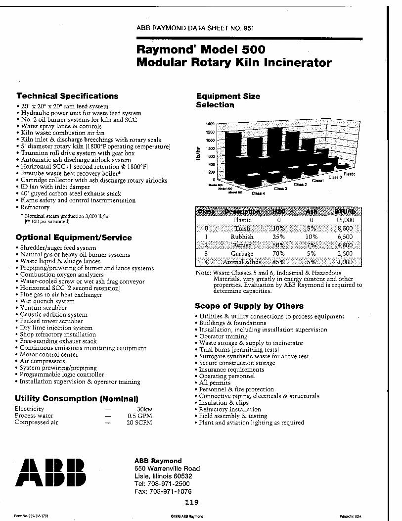
ABB RAYMOND DATA SHEET NO. 951
Raymond" Model 500 Modular Rotary Kiln Incinerator
Technical Specifications • 20" x 20" x 20" ram feed system • Hydraulic power unit for waste feed system • No. 2 oil burner systems for kiln and SCC • Water spray lance & controls • Kiln waste combustion air fan • Kiln inlet & discharge breechings with rotary seals • 5' diameter rotary kün (1800°F operating temperature) • Trunnion roll drive system with gear box • Automatic ash discharge airlock system • Horizontal SCC (1 second retention @ 1800°F) • Firetube waste heat recovery boiler* • Cartridge collector with ash discharge rotary airlocks • ID fan with inlet damper • 40' guyed carbon steel exhaust stack • Flame safety and control instrumentation • Refractory
* Nominal steam production 3,000 lb/hr (@ 100 psi saturated)
Optional Equipment/Service • Shredder/auger feed system • Natural gas or heavy oil burner systems • Waste liquid &. sludge lances • Prepiping/prewiring of burner and lance systems • Combustion oxygen analyzers • Water-cooled screw or wet ash drag conveyor • Horizontal SCC (2 second retention) • Flue gas to air heat exchanger • Wet quench system • Venturi scrubber • Caustic addition system • Packed tower scrubber • Dry lime injection system • Shop refractory installation • Free-standing exhaust stack • Continuous emissions monitoring equipment • Motor control center • Air compressors • System prewiring/prepiping • Programmable logic controller • Installation supervision & operator training
Utility Consumption (Nominal) Electricity — 30kw Process water — 0.5 GPM Compressed air — 20 SCFM
Equipment Size Selection
Class 3 Class 2
Classl Class 0
Plastic
Class 4
Class Description H20 0
———————
6 BTU/Ib 15,000 Plastic
0 Trash 10% 5% 8,500 1 Rubbish 25% 10% 6,500 2 Refuse 50% • 7% 4,800 3 Garbage 70% 5% 2,500 4 Animal solids 85% 5% 1,000
Note: Waste Classes 5 and 6, Industrial &. Hazardous Materials, vary greatly in energy content and other properties. Evaluation by ABB Raymond is required to determine capacities.
Scope of Supply by Others • Utilities & utility connections to process equipment • Buildings & foundations • Installation, including installation supervision • Operator training • Waste storage &. supply to incinerator • Trial burns (permitting tests) • Surrogate synthetic waste for above test • Secure construction storage • Insurance requirements • Operating personnel • All permits • Personnel & fire protection • Connective piping, electricals & structurals • Insulation & clips • Refractory installation • Field assembly & testing • Plant and aviation lighting as required
A I» II mi» i» FomiNo.951-3M-1791
ABB Raymond 650 Warrenville Road Lisle, Illinois 60532 Tel: 708-971-2500 Fax:708-971-1076
119
01995 ABB Raymond Printed in USA
• SST instrument air tubing
The following equipment manufacturers, or equivalents, are utilized:
Pressure Switches - S.O.R. Pressure Gauges - Ashcroft, North American Throttling Control Valves - Fisher, Jamesbury Ball Valves - North American, Jamesbury On/Off Control Valves - Jamesbury, Maxon Pressure Regulators - North American, Fisher Solenoid Valves - ASCO Orifices - North American Electronic Pneumatic Converters - Fisher Controls, Rosemont Tubing Fittings - Swagelock
The combustion trains are preassembled skids, with utility piping to skids, utility from skids to burner by customer. Burner train components are FM approved and NEMA 4, but are not for installation in an electrically classified area.
Flame Protection (for Kiln and SCC)
A series of interlocks incorporate preignition purge period, automatic fuel shut-off valves, low oil pressure gas switch, low atomization pressure switch, low combustion air pressure switch and flame supervision. The applicable Honeywell, or equal items below are featured in a pre-wired control panel:
UV flame detectors Flame relays Purge timers
c. Rotary Kiln System
Inlet Head
Circular breeching is enclosed by the kiln inlet. Seal rings around the periphery of the inlet head prevent excessive air leakage into the primary combustion chamber. Breeching is 0.25" carbon steel with carbon steel plate supports. Seals are Webbco style, segmented stainless steel construction, with sintered wear pads riding on the inlet head O.D.
Kiln
The kiln cylinder is mounted inside two riding rings, each of which rotates on a pair of trunnions. The kiln cylinder is sloped slightly downhill towards the discharge end to promote travel of feed material from inlet to discharge. Solid
120
residence time through the kiln is controlled by varying the rotational speed of the cylinder. It has an overall size of 5' diameter x 14' long. The cylinder is constructed of 1/2" carbon steel A-36 plate, rolled and welded with reinforced areas of 1.0" carbon steel A-3 6 plate in areas of riding rings and driven element, rolled and welded. The last 18" of the cylinder is made from Inconel 601.
Riding Rings
The two riding rings are located approximately 1/5 of the overall cylinder length from each end, and are secured to the cylinder by pads mounted beneath the rings and welded to the reinforced sections of the cylinder. The riding rings are aligned longitudinally by pairs of guide lugs welded to the pads. The rings are aligned so that they are mutually parallel and are normal to the axis of the cylinder. Riding rings are constructed of carbon Class "C: locomotive steel, seamless, rolled and forged, machined on all surfaces.
Girt Gear
Kiln spur gear is machined as one piece and then split into two halves for ease of mounting and disassembly. The gear halves are mounted on the reinforced areas of the cylinder and positioned next to the uphill riding ring which is restricted from axial movement by the thrust rolls. The two halves are mounted on the cylinder with several steel strips along the circumference which act as springs. The "springs" are welded to the cylinder and bolted to the gear halves. The gear halves are fastened together with bolted plates. The gear can be removed and reversed for extended life. Gear pitch diameter is 70" with 72 full depth cut teeth on a 2" face. Gear is constructed of C-1045 steel, fully machined teeth flame hardened to 400/450 Brinell.
Trunnion Rolls and Thrust Roll Assembly
Arrangement - Two (2) trunnion rolls are mounted on each support base which are positioned under each riding ring. Each roll is heat shrunk on a shaft which is support by pillow block roller bearings. Grease fittings are provided for lubrication. Support bases feature a machined surface with jack screws for easy adjust of the bearings.
A thrust roll is mounted on each side of the uphill riding ring to restrict axial movement of the cylinder assembly. Each thrust roll is mounted on a fixed shaft which is supported by pillow block bearings. Each shaft is integral to an adjustable structural steel bracket which is bolted to the trunnion roll base.
121
Guards enclose pinch points between trunnion rolls and riding rings. Graphite blocks with guides are furnished for surface lubrication between each trunnion roll and riding ring.
Trunnion rolls are constructed of C-1045 forged steel, tread flame hardened to 400/450 Brinell. Their shafts are C-1141 hot rolled steel with eight SFK anti-friction roller bearings.
Thrust rolls are C-1045 forged steel, tread hardened to 400/450 Brinell on a C-1141 hot rolled steel shaft. There are two bearings required per roll- Timken roller bearings, or equivalent. The top of the thrust roll has a dust-proof spherical cap and lower end hub is closed with labyrinth grease seals.
Cylinder Drive Assembly
Mechanical speed reducer, electric drive motor and all couplings are furnished on a common base plate. The base plate includes a sole plate with adjusting lugs for aligning the gear and pinion. A drive guard encloses the driving elements and is shipped separately in flanged sections with mounting tabs for field attachment to the drive base. All couplings are provided with OSHA safety guards. The speed reducer is a Falk, Rexnord or equivalent with a speed range of 0.2 rpm to 2.0 rpm. Drive motor is 2 HP, 1750 rpm, TEFC, 1.15 SF.
Discharge Breeching
Breeching is a refractory lined chamber with nominal dimensions of 8' high x 8' wide x 8' depth. The bottom section of the breeching is tapered for connection to a bottom ash removal device. Breeching is carbon steel with a Täte Jones sight port or equivalent. Seals are Webbco style, segmented stainless steel construction, with sintered wear pads riding on the cylinder O.D.
Refractory
The kiln inlet head, cylinder and discharge breeching are furnished with a refractory lining. The cylinder is lined with refractory along its entire length. The feed end of the cylinder is supplied with a refractory dam ring to prevent back spillage of solid feeds through the inlet seal.
Refractory Materials:
Inlet Head Castable, 50% alumina
Inlet Dam Plastic 60% alumina
122
Kiln Cylinder Brick, 60% alumina
Discharge Breeching Plastic, 60% alumina
d. Secondary Combustion Chamber System
Secondary Combustion Chamber (SCC)
Chamber is a cylindrical refractory-lined chamber with supporting steel, burner opening, and monitoring ports. The approximate internal dimensions of the SCC are 34" wide, 76" tall and 20' long. The average residence time in the SCC is 2.0 seconds. SCC Shell is constructed of 1/4" carbon steel plate, rolled and welded.
SCC Auxiliary Fuel Burner
Burner is mounted on the SCC burning natural gas or No. 2 fuel oil with a maximum gross heat of 2,000,000 Btu/hr. The burner train is by North American Manufacturing and features the following:
• No wiretrays. Galvanized steel conduit w/appropriate length flexible connections to instruments.
• Channel construction of frame • SST instrument air tubing
The following equipment manufacturers, or equivalents, are utilized:
Pressure Switches - S.O.R. Pressure Gauges - Ashcroft, North American Throttling Control Valves - Fisher, Jamesbury Ball Valves - North American, Jamesbury On/Off Control Valves - Jamesbury, Maxon Pressure Regulators - North American, Fisher Solenoid Valves - ASCO Orifices - North American Electronic Pneumatic Converters - Fisher Controls, Rosemont Tubing Fittings - Swagelock
The combustion trains are preassembled skids with utility piping to skids and from skids to burner. Burner train components are FM approved and NEMA 4, but are not for installation in an electrically classified area.
Emergency Stack
A refractory lined duct with a refractory lined stack cap is provided on top of the SCC and held in the closed position during normal operation. Stack is carbon steel, refractory
123
lined with seal, includes operator and counter weights.
SCC Refractory
The SCC is refractory lined throughout its length.
Refractory Materials:
SCC 6" castable
Emergency Stack 6" castable
Stack Cap 6" castable
e. Heat Recovery/Flue Gas Cleaning Systems
Air-to-Gas Heat Exchanger
Specific design will be completed later.
Cartridge Collector
Cartridge collector is a Wheelabrator Cartridge Collector constructed of 3/16" carbon steel plate. Air-to-cloth ratio is 3.7:1 at 100% capacity. Filter cartridges are woven fiberglass with acid resistant finish and 5% spares. The rotary airlock is a six vane with outboard mounted anti- friction bearings. Rotor is removable through end plate and independently driven by 1/2 hp TEFC gear head motor.
ID Fan
It is a carbon steel centrifugal fan with flanged inlet, and outlet, and is complete with shaft seals access doors and drains. Flow capacity is 2500 acfm, 20" SP, 400°F. Brake horsepower is 50 hp. The manufacturer will be Buffalo Forge, or equivalent with a Reliance motor, or equivalent.
Packed Bed Scrubber
Packed bed scrubber will remove acids from gas to subcool gas. The tower is of FRP and includes plastic packing, recycle tank, ports, recycle pump, indicator, feed tank, pump and valves, pH control, alarms and subcooling loop. The vent stack is integral with the packed tower outlet.
Caustic Feed System
One caustic feed system will be provided to include the following components:
pH probe and transmitter
124
pH PID controller Caustic metering pump with 4-20 mA stroke adjustment and motor
f. Instrumentation and Controls
Process control system will include the following Allen- Bradley, or equivalent PLC based on a preliminary I/O point count:
PLC 5/25 Power supply with cable 8K word memory expansion PC interface; Analog input cards (8 inputs per card) Analog output card (4 outputs per card) Thermocouple input cards (8 inputs per card) Digital input cards (16 inputs per card) Digital input fuse cards (16 per card) Digital output cards (16 outputs per card) Digital output fuse cards (16 per card) RS 232 Communications card PID controllers networked to PC I/O chassis Remote rack I/O modules 486 PC clone (industrial grade) with mouse and 20"
color monitor 40 meg removable media data logging device
Operating and Capital Costs
Capital costs were developed for a 150 pounds per hour explosive waste incinerator and the operating costs were also developed for two disposal scenarios.
All costs are in 1995 dollars.
1. Operating Costs
Preliminary operating data has been developed for disposal rates of 150 pounds per hour with 3-8-7 (720 hrs/mo) and 1-8-5 (176 hrs/mo) shift scenarios. Costs are summarized in Table V - 3, Monthly Operations Costs. Estimated unit disposal cost is $1.28 per pound at full disposal capacity and $1.49 per pound when disposal is one 8 hour shift operating five days per week.
125
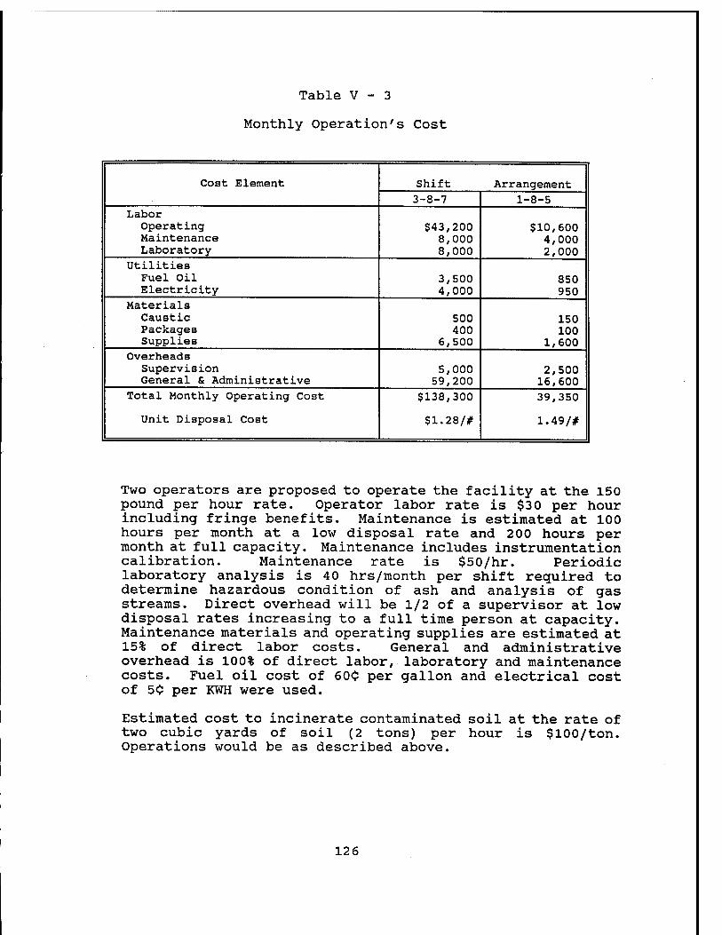
Table V - 3
Monthly Operation's Cost
Cost Element Shift Arrangement 3-8-7 1-8-5
Labor Operating Maintenance Laboratory
$43,200 8,000 8,000
$10,600 4,000 2,000
Utilities Fuel Oil Electricity
3,500 4,000
850 950
Materials Caustic Packages Supplies
500 400
6,500
150 100
1,600 Overheads
Supervision General & Administrative
5,000 59,200
2,500 16,600
Total Monthly Operating Cost
Unit Disposal Cost
$138,300
$1.28/#
39,350
1.49/#
Two operators are proposed to operate the facility at the 150 pound per hour rate. Operator labor rate is $30 per hour including fringe benefits. Maintenance is estimated at 100 hours per month at a low disposal rate and 200 hours per month at full capacity. Maintenance includes instrumentation calibration. Maintenance rate is $50/hr. Periodic laboratory analysis is 40 hrs/month per shift required to determine hazardous condition of ash and analysis of gas streams. Direct overhead will be 1/2 of a supervisor at low disposal rates increasing to a full time person at capacity. Maintenance materials and operating supplies are estimated at 15% of direct labor costs. General and administrative overhead is 100% of direct labor, laboratory and maintenance costs. Fuel oil cost of 600 per gallon and electrical cost of 50 per KWH were used.
Estimated cost to incinerate contaminated soil at the rate of two cubic yards of soil (2 tons) per hour is $100/ton. Operations would be as described above.
126
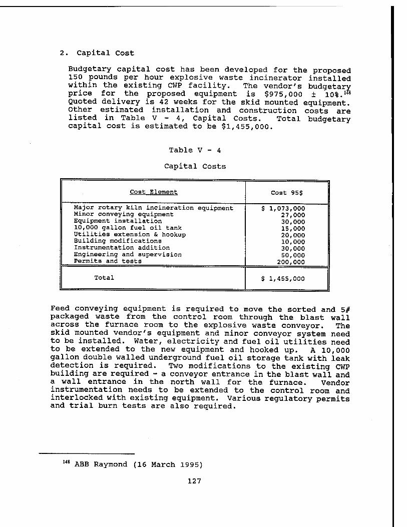
. Capital Cost
Budgetary capital cost has been developed for the proposed 150 pounds per hour explosive waste incinerator installed within the existing CWP facility. The vendor's budgetary price for the proposed equipment is $975,000 ± 10%. ^ Quoted delivery is 42 weeks for the skid mounted equipment. Other estimated installation and construction costs are listed in Table V - 4, Capital Costs. Total budgetary capital cost is estimated to be $1,455,000.
Table V - 4
Capital Costs
Cost Element
Major rotary kiln incineration equipment Minor conveying equipment Equipment installation 10,000 gallon fuel oil tank Utilities extension & hookup Building modifications Instrumentation addition Engineering and supervision Permits and tests
Total
Cost 95$
$ 1,073,000 27,000 30,000 15,000 20,000 10,000 30,000 50,000
200,000
$ 1,455,000
Feed conveying equipment is required to move the sorted and 5# packaged waste from the control room through the blast wall across the furnace room to the explosive waste conveyor. The skid mounted vendor's equipment and minor conveyor system need to be installed. Water, electricity and fuel oil utilities need to be extended to the new equipment and hooked up. A 10,000 gallon double walled underground fuel oil storage tank with leak detection is required. Two modifications to the existing CWP building are required - a conveyor entrance in the blast wall and a wall entrance in the north wall for the furnace. Vendor instrumentation needs to be extended to the control room and interlocked with existing equipment. Various regulatory permits and trial burn tests are also required.
148 ABB Raymond (16 March 1995)
127
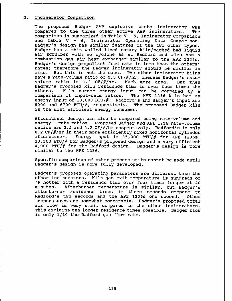
D. Incinerator Comparison
The proposed Badger AAP explosive waste incinerator was compared to the three other active AAP incinerators. The comparison is summarized in Table V - 5, Incinerator Comparison and Table V - 6, Incinerator Operating Data Comparison. Badger's design has similar features of the two other types. Badger has a thin walled lined rotary kiln/packed bed liquid air scrubber with no cyclone as at Radford and also has a combustion gas air heat exchanger similar to the APE 1236s. Badger's design propellant feed rate is less than the others' rates; therefore the Badger incinerator should be smaller in size. But this is not the case. The other incinerator kilns have a rate-volume ratio of 0.5 CF/#/hr, whereas Badger's rate- volume ratio is 1.2 CF/#/hr. Much more area. But then Badger's proposed kiln residence time is over four times the others. Kiln burner energy input can be compared by a comparison of input-rate ratios. The APE 1236 kiln has an energy input of 18,000 BTU/#. Radford's and Badger's input are 8900 and 6700 BTU/#, respectively. The proposed Badger kiln is the most efficient energy consumer.
Afterburner design can also be compared using rate-volume and energy - rate ratios. Proposed Badger and APE 1236 rate-volume ratios are 2.5 and 2.2 CF/#/hr respectively. Radford's is only 0.2 CF/#/hr in their more efficiently mixed horizontal cylinder afterburner. Energy input is 35,000 BTU/# for APE 1236s, 13,300 BTU/# for Badger's proposed design and a very efficient 4,900 BTU/# for the Radford design. Badger's design is more similar to the APE 1236.
Specific comparison of other process units cannot be made until Badger's design is more fully developed.
Badger's proposed operating parameters are different than the other incinerators. Kiln gas exit temperature is hundreds of °F hotter with a residence time over four times longer at 40 minutes. Afterburner temperature is similar, but Badger's afterburner residence times is three seconds compare to Radford's two seconds and the APE 1236s one second. Other temperatures are somewhat comparable. Badger's proposed total air flow is very small compared to the other incinerators. This explains the longer residence times possible. Badger flow is only 1/10 the Radford gas flow rate.
128
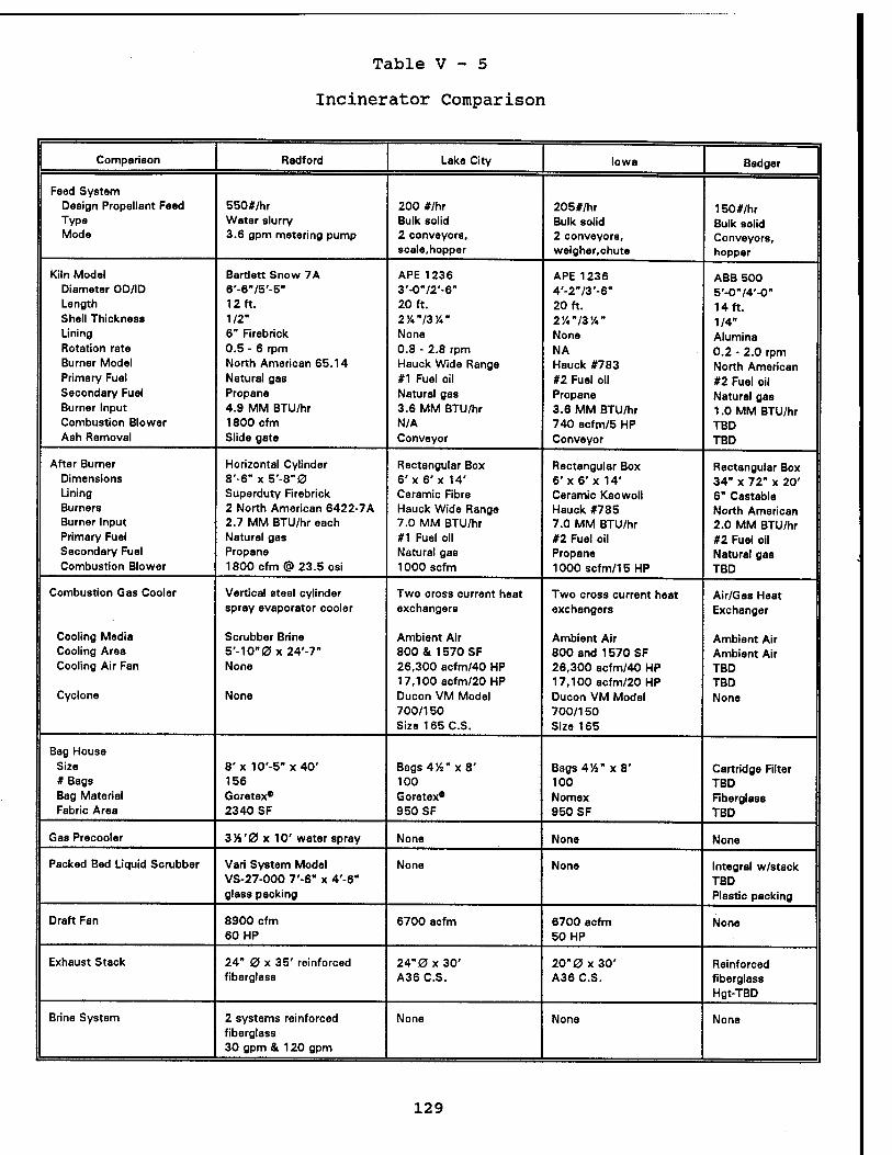
Table V - 5
Incinerator Comparison
Comparison Radford Lake City Iowa Badger
Feed System Design Propellant Feed 550#/hr 200 #/hr 205#/hr 150#/hr Type Water slurry Bulk solid Bulk solid Bulk solid Mode 3.6 gpm metering pump 2 conveyors. 2 conveyors, Conveyors,
scale,hopper weigher,chute hopper
Kiln Model Bartlett Snow 7A APE 1236 APE 1236 ABB 500 Diameter OD/ID 6'-6"/5'-5" 3'-0"/2'-6" 4'-2"/3'-6" 5'-0"/4'-0" Length 12 ft. 20 ft. 20 ft. 14 ft. Shell Thickness 1/2" 2'/4"/3y4" 2/4"/3'/4" 1/4" Lining 6" Firebrick None None Alumina Rotation rate 0.5 - 6 rpm 0.8 - 2.8 rpm NA 0.2 - 2.0 rpm Burner Model North American 65.14 Hauck Wide Range Hauck #783 North American Primary Fuel Natural gas #1 Fuel oil #2 Fuel oil #2 Fuel oil Secondary Fuel Propane Natural gas Propane Natural gas Burner Input 4.9 MM BTU/hr 3.6 MM BTU/hr 3.6 MM BTU/hr 1.0 MM BTU/hr Combustion Blower 1800 cfm N/A 740 acfm/5 HP TBD Ash Removal Slide gate Conveyor Conveyor TBD
After Burner Horizontal Cylinder Rectangular Box Rectangular Box Rectangular Box Dimensions 8'-6" x 5'-8"0 6'x 6'x 14' 6'x 6'x 14' 34" x 72" x 20' Lining Superduty Firebrick Ceramic Fibre Ceramic Kaowoll 6" Castable Burners 2 North American 6422-7A Hauck Wide Range Hauck #785 North American Burner Input 2.7 MM BTU/hr each 7.0 MM BTU/hr 7.0 MM BTU/hr 2.0 MM BTU/hr Primary Fuel Natural gas #1 Fuel oil #2 Fuel oil #2 Fuel oil Secondary Fuel Propane Natural gas Propane Natural gas Combustion Blower 1800 cfm @ 23.5 osi 1000 scfm 1000scfm/15HP TBD
Combustion Gas Cooler Vertical steel cylinder Two cross current heat Two cross current heat Air/Gas Heat spray evaporator cooler exchangers exchangers Exchanger
Cooling Media Scrubber Brine Ambient Air Ambient Air Ambient Air Cooling Area 5'-1O"0 x 24'-7" 800 & 1570 SF 800 and 1570 SF Ambient Air Cooling Air Fan None 26,300 acfm/40 HP 26,300 acfm/40 HP TBD
17,100 acfm/20 HP 17,100 acfm/20 HP TBD Cyclone None Ducon VM Model
700/150 Size 165 C.S.
Ducon VM Model 700/150 Size 165
None
Bag House Size 8'x 10'-5"x40' Bags 454" x 8' Bags 414" x 8' Cartridge Filter # Bags 156 100 100 TBD Bag Material Goretex* Goretex* Nomex Fiberglass Fabric Area 2340 SF 950 SF 950 SF TBD
Gas Precooler 354'0 x 10' water spray None None None
Packed Bed Liquid Scrubber Vari System Model VS-27-000 7'-6" x 4'-6" glass packing
None None Integral w/stack TBD Plastic packing
Draft Fan 8900 cfm 60 HP
6700 acfm 6700 acfm 50 HP
None
Exhaust Stack 24" 0 x 35' reinforced 24"0x3O' 20" 0 x 30' Reinforced fiberglass A36 C.S. A36 C.S. fiberglass
Hgt-TBD
Brine System 2 systems reinforced fiberglass 30 gpm & 120 gpm
None None None
129
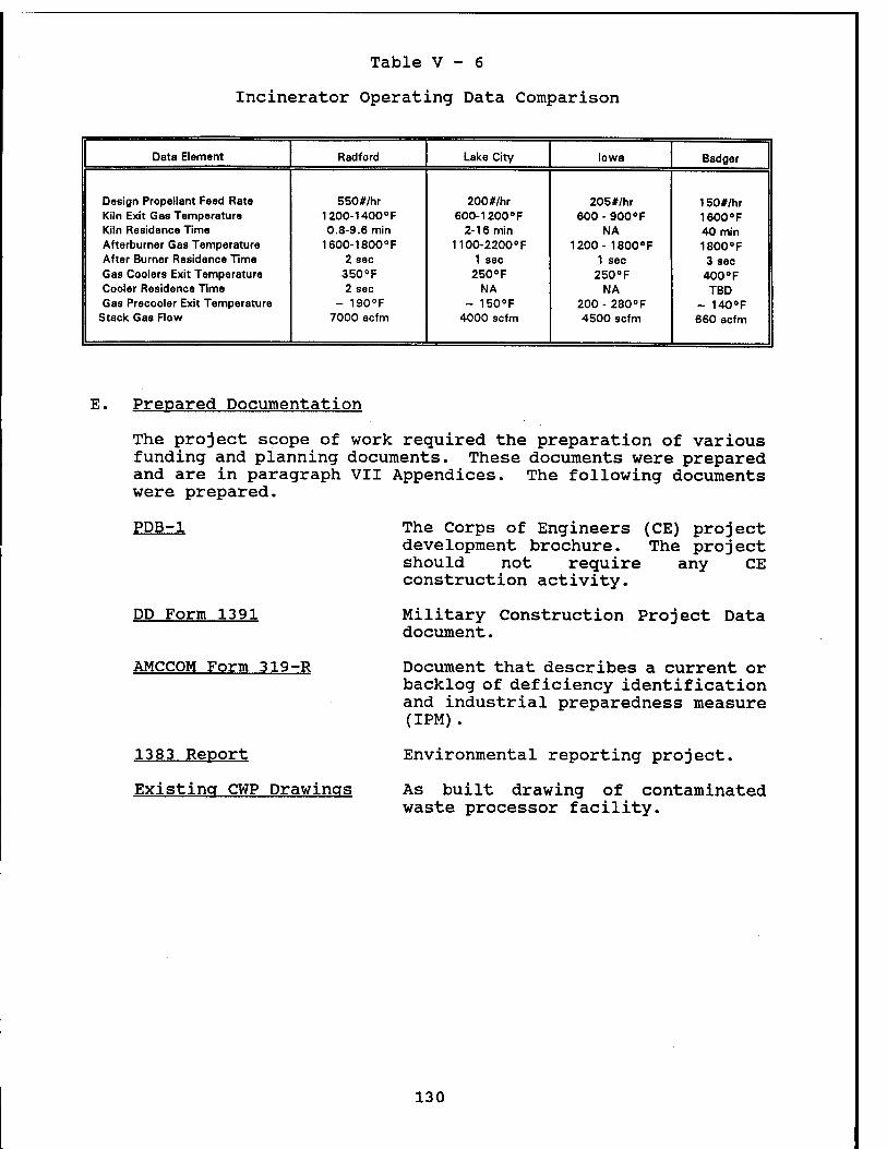
Table V - 6
Incinerator Operating Data Comparison
Data Element Radford Lake City Iowa Badger
Design Propellent Feed Rate 550#/hr 200#/hr 205#/hr 150#/hr Kiln Exit Gas Temperature 1200-1400 °F 600-1200 °F 600 - 900 °F 1600°F Kiln Residence Time 0.8-9.6 min 2-16 min NA 40 min Afterburner Gas Temperature 1600-1800 °F 1100-2200 8F 1200- 1800°F 1800°F After Burner Residence Time 2 sec 1 sec 1 sec 3 sec Gas Coolers Exit Temperature 350°F 250 °F 250°F 400°F Cooler Residence Time 2 sec NA NA TBD Gas Precooler Exit Temperature - 190°F ~ 150°F 200-280 °F - 140°F
Stack Gas Flow 7000 acfm 4000 scfm 4500 scfm 660 acfm
E. Prepared Documentation
The project scope of work required the preparation of various funding and planning documents. These documents were prepared and are in paragraph VII Appendices. The following documents were prepared.
PDB-1
DP Form 1391
AMCCOM Form 319-R
1383 Report
Existing CWP Drawings
The Corps of Engineers (CE) project development brochure. The project should not require any CE construction activity.
Military Construction Project Data document.
Document that describes a current or backlog of deficiency identification and industrial preparedness measure (IPM).
Environmental reporting project.
As built drawing of contaminated waste processor facility.
130
VI - BIBLIOGRAPHY
ABB Environmental Services, Feasibility Study Report Data Item A009. Project No. 6853-09, Remedial Investigation/Feasibility Study, Badger Army Ammunition Plant, Portland, ME, August 1994.
ABB Raymond, Rotary Kiln Incineration System. Proposal No. 1840-1, Naperville, IL, 16 March 1995.
Robert E. Adams, et al, Evaluation of POHC and PIC Screening Methods. Atmospheric Research and Exposure Assessment Laboratory, Research Triangle Park, NC, January 1993. NTIS PB93-144137
J. R. Albritton, et al, Audit Materials for Semivolatile Organic Measurements During Hazardous Waste Trial Burns. Project Summary, U. S. Environmental Protection Agency, Atmospheric Research and Exposure Assessment Laboratory, Research Triangle Park, NC, August 1990. EPA/600/S3-90/033
AMC-R 385-10, Safety Manual. U. S. Army Material Command, 1994.
R. G. Anderson, et al, Results of Trial Burn on Armv Deactivation Furnaces Upgrade to Meet RCRA. presented at 25th DOD Explosives Safety Seminar, Anaheim, CA, August 18-20, 1992.
Badger AAP, Production. Planning S Inventory Control Records. OB 707 and OB 97, Badger Army Ammunition Plant, Baraboo, WI, 1968-74.
Badger AAP, Wood Burning Records, CWP, Badger Army Ammunition Plant, Baraboo, WI, 1983-87.
Edwin Barth, Approaches for the Remediation of Federal Facility Sites Contaminated with Explosive or Radioactive Wastes. Handbook, Office of Research and Development, U. S. Environmental Protection Agency, Cincinnati, OH, September 1993. EPA/625/R-93/013. NTIS PB94-144656
T. M. Benziger, et al, Destruction of Waste Energetic Materials Using Base Hydrolysis. Proceedings of the 1993 Incineration Conference. NTIS DE93- 012738
Blank and Wesselink & Associates, Explosive Waste Incinerator Facilities. Study Report, Decatur, IL, for Omaha District, Corps of Engineers, Omaha, NE, 18 March 1977.
W. M. Bradshaw, Pilot-Scale Testing of a Fuel Oil - Explosives Cofirino Process for Recovering Energy from Waste Explosives. Final Technical Report, Oak Ridge National Laboratory, Oak Ridge, TN, for U. S. Army Toxic and Hazardous Materials Agency, Aberdeen Proving Grounds, MD, August 1988. NTIS DE89-013657
Calvin A. Brunner, Handbook of Incineration Systems. McGraw Hill, Inc., New York, NY, 1991.
Dan Burch and Mike Johnson, Reformulation/Reuse of Explosives and Propellants. Presented at ADPA Energetic Materials Technical Symposium Orlando, FL, 21-24 March 1994.
Clarence A. demons, Experience in Incineration Applicable to Superfund Site Remediation, Center for Environmental Research Information, Cincinnati, OH, December 1988. EPA/625/9-88/00840 Code of Federal Regulations, Part 264, Subpart O Permitted Incinerator Standards as of 1 July 1993.
131
40 Code of Federal Regulations Part 270, Permitting Requirements as of 1 July 1993
40 Code of Federal Regulations Part 272, Approved State Hazardous Waste Management Programs as of 1 July 1993
DD Form 1391, Military Construction Project Data FY79, 12 Oct 1976. Project Number T00400, Incinerator, Explosive Waste.
C. R. Dempsey and E. T. Oppelt, Incineration of Hazardous Waste; A Critical Review Update, Journal of Air & Waste Management Association, Vol 43, January 1993, pg 25-73. EPA/600/J-93/144. NTIS PB93-185916
Clyde R. Dempsey and Donald A. Oberacker, Overview of Incineration Performance, Risk Reduction Engineering Laboratory, U. S. Environmental Protection Agency, Cincinnati, OH, November 1988. EPA/600/D-88/230. NTIS PB89-120851
Department of the Army, SARBA-SE Letter, 29 Dec 1976, subject Safety Site Plan FY79 MCA Program: Project T00400 Explosive Waste Incinerator, Project T00600 Contaminated Waste Incinerator.
Lori DeRose and Vanessa Musgrave, et al, Hazardous Waste Incineration; Questions and Answers. U. S. Environmental Protection
Agency, Washington, D.C., 5 April 1988. EPA/530-SW-88/018
R. Eric Dotseth and David W. Ling, Munitions Demilitarization Through Disassembly and Resource Recovery. Presented at ADPA Energetic Materials Technical Symposium Orlando, FL, 21-24 March 1994.
Richard C. Doyle and Judith F. Kitchens, Composting of Soils/Sediments and Sludges Containing Toxic Organics Including High Energy Explosives. Final Report, IIT Research Institute, Newington, VA, for Office of Research and Development, U. S. Department of Energy, July 1993. DOE/CH-9208. NTIS DE94-004325
DRE Technologies, Inc., Trial Burn Plan for Waste Propellant Incinerator with Upgraded Air Pollution Control System at Radford AAP. June 1992
EPA, Compilation of Air Pollutant Emission Factors for AP-42. Third Edition, Supplement No. 10, U. S. Environmental Protection Agency, Office of Air and Waste Management, February 1980. PB80-1990-45
EPA, Standards Applicable to Owners and Operators of Hazardous Waste Treatment. Storage. and Disposal Facilities; Consolidated Permit Regulations. Federal Register, 47 (No. 122) 27516-27535, 24 June 1982.
EPA, Standards of Performance for New Stationary Sources and Final Guidelines; Final Rules, Federal Register, 56 (No. 28), 5488-5527, February 11, 1991.
Irving Forsten, et al, Development Trends in the Incineration of Waste Explosives and Propellants, U. S. Army Manufacturing Technology Directorate, Picatinny Arsenal, Dover, NJ, May 1976. NTIS AD-A024513
Millard M. Garrison and John Serino, Jr, The Conversion of Energetic Materials into Clean Alternate Commercial Energy Forms using Induction Coupled Plasma, Presented at ADPA Energetic Materials Technical Symposium Orlando, FL, 21-24 March 1994.
132
J. M. Genser, et al, Alternatives for Hazardous Waste Management in the Organic Chemical. Pesticides and Explosives Industries, Final Report, Processes Research, Inc., Cincinnati, OH, for Environmental Protection Agency, Hazardous Waste Management Division, September 2, 1977. NTIS PB278059
P. Gorman, et al, Practical Guide - Trial Burns for Hazardous Waste Incinerators, Project Summary, U. S. Environmental Protection Agency, Hazardous Waste Engineering Research Laboratory, Cincinnati, OH, July 1986. EPA/600/S2-86/050
J. L. Harrison, et al, Mound Facility Explosives Incinerator. DE Contract No. ACO4-76-DP00053, Mound Facility, Miamisburg, OH, 1980. NTIS MLM-2762
Katherine L. Heineken, et al, Subpart X Emissions Evaluation for U. S. Air Force Munitions, Presented at ADPA Energetic Materials Technical Symposium Orlando, FL, 21-24 March 1994.
James R. Hendricks and Joseph S. Klimek, Adams Process Demilitarizes Energetics, Presented at ADPA Energetic Materials Technical Symposium Orlando, FL, 21-24 March 1994.
F. I. Honea, et al, Disposal of Waste or Excess High Explosives, Mason & Hanger, Silas Mason Co. Inc., Burlington Pantex ERDA Plant for Energy Research and Development Administration, Albuquerque, NM, Progress Reports, April 1973 - September 1975, NTIS: MHSMP-75-52, MHSMP-75-15, MHSMP-75-3, MHSMP-74-31, MHSMP-74-2, MHSMP-73-40, and MHSMP-73-29.
Randall W. Hurd and George L. Clink, Energetic Materials Reclamation and Solvent Recycling, Presented at ADPA Energetic Materials Technical Symposium Orlando, FL, 21-24 March 1994.
Iowa AAP, Hazardous Waste Management Permit. EPA RCRA ID #IA7213820445, August 1994.
Lou D. Johnson and M. H. Spritzer, The Crvofracture Process for Chemical Munition Demilitarization, Presented at ADPA Energetic Materials Technical Symposium Orlando, FL, 21-24 March 1994.
Michael Johnson, et al, Pyrotechnics Incineration, Presented at ADPA Energetic Materials Technical Symposium Orlando, FL, 21-24 March 1994.
Barbara Katinsky, 21st Annual Buyers' Guide, World Wastes, August 1994
Joan Kenney, et al, RCRA Part B Permit. Feasibility and Plan of Operation Report for the Open Burning Thermal Treatment unit, at the Badger Army Ammunition Plant, Baraboo, WI, with Appendices K, L and M, July 1993.
Todd A. Kimmeil, et al, The Munitions Provisions of the Federal Facility Compliance Act, Presented at ADPA 20th Environmental Symposium and Exhibition, San Antonio, TX, March 1994. NTIS DE94-008462
Larry M. Klinger and Perry L. Abellera, Joule-Heated Glass Furnace Processing of a Highly Agueous Hazardous Waste Stream, EG&G Mound Applied Technologies, Miamisburg, Ohio, March 17, 1989. NTIS DE89-008958
R. A. Knudsen, Hazard Analysis of Pollution Abatement Technicrues. Volume I of III, Final Report, Hercules, Incorporated, Cumberland, MD, for Picatinny Arsenal, Dover, NJ, June 1994. NTIS AD-A017462
John Krukowski, Incinerators Supply Lesson in Supply and Demand, Pollution Engineering, December 1993
133
Norm Kulujian, Permitting Hazardous Waste Incinerators. Seminar Publication, Seminars for Hazardous Waste Incinerator Permit Writers, Inspectors, and Operators, Center for Environmental Research Information, Cincinnati, OH, September 1987. EPA/625/4-87/017
C. A. LaJeunesse, et al, Supercritical Water Oxidation of Colored Smoke. Dve, and Pyrotechnic Compositions, Final Report: Pilot Plant Conceptual Design, Sandia National Laboratories, Albuquerque, NM, November 1993. DTIS DE94-003140
Lake City AAP, Explosive Waste Incinerator Training Program. Manual
Paul M. Lemieux, et al, Transient Suppression Packaging for Reduced Emissions from Rotary Kiln Incinerators. Combustion Science and Technology, Vol 85 (1992) pp 203-216, 1992. EPA/600/J-93/245. NTIS PB93-212520
Michael P. Madden and William I. Johnson, Installation Restoration and Hazardous Waste Control Technologies. 1992 Edition, Report Number CETHA- TS-CR-92053, IIT Research Institute, Bartlesville, OK, for U. S. Army Corps of Engineers Toxic and Hazardous Materials Agency, Aberdeen Proving Grounds, MD, November 1992.
Justice A. Manning, Operational Parameters for Hazardous Waste Combustion Devices. Seminar Publication, Center for Environmental Research Information, Cincinnati, OH, October 1993. EPA/625/R-93/008.
Justice A. Manning, Quality Assurance/Quality Control (OA/OC1 Procedures for Hazardous Waste Incineration. Handbook, Center for Environmental Research Information, Cincinnati, OH, January 1990. EPA/625/6-89/023
L. Manson and S. Unger, Hazardous Material Incinerator Design Criteria. TRW, Redondo Beach, CA, for Industrial Environmental Research Laboratory, Cincinnati, OH, October 1979. EPA/600/2-79/198
Michael A. Major and John C. Amos, Incineration of Explosive Contaminated Soil as a Means of Site Remediation. Technical Report #9214, U. S. Army Biomedical Research & Development Laboratory, Fort Detrick, Frederick, MD, November 1992.
Military Munitions Waste Working Group Report. Federal Advisory Committee to Develop On-Site Innovative Technologies, Paper presented at Governor's Association, Denver CO, Nov 30, 1993. NTIS 94001185396
Richard K. Miller, Industry Execs See Bright Future For Incineration. World Wastes, October 1994
Edwin E. Muniz, Incineration of Energetic Materials at the Chemical Stockpile Disposal Program, Presented at ADPA Energetic Materials Technical Symposium Orlando, FL, 21-24 March 1994.
W. O. Munson, et al, Task 1 Trade Study: Alternate Propellant Waste Disposal Methods TD No. 8-(4C). Thiokol Corporation Space Operations, Brigham City, UT, for National Aeronautics and Space Administration, Marshall Flight Center, AL, 7 June 1991. NASA 30490
Craig A. Myler, et al, Use of Waste Energetic Materials as a Fuel Supplement in Utility Boilers, U. S. Department of Energy, Oak Ridge National Laboratory, Oak Ridge, TN, 1994. DE89-016-08D. NTIS DE89-016080
Craig A. Myler, et al, Use of Waste Energetic Materials as a Fuel Supplement. Journal of Hazardous Materials, 26, 1991, pg 333-342.
134
Rachel K. Nihart, et al, Continuous Performance Monitoring Techniques for Hazardous Waste Incinerators. Project Summary, United States Environmental Protection Agency, Air and energy Engineering Research Laboratory, Research Triangle Park, NC, August 1989. EPA/600/S2-89/021.
John W. Noland and Wayne E. Sisk, Incineration of Explosives Contaminated Soils, presented at ADPA 13th Annual Environmental Systems Symposium, Bethesda, MD, 20-22 March 1984. NTIS AD-P004142
John W. Noland, et al, Task 2. Incineration Test of Explosives Contaminated Soils at Savanna Army Depot Activity, Final Report, Ü. S. Army Toxic & Hazardous Materials Agency, Aberdeen Proving Ground, Edgewood Area, MD, April 1984
NTIS, Remediation of Explosive Materials, Citations from the Energy Base, National Technical Information Service, Springfield, VA, November 1994. NTIS PB95-859252
E. Timothy Oppelt, Guidance on Setting Permit Conditions and Reporting Trial Burn Results, Handbook, Volume II of the Hazardous Waste Incineration Guidance Series, Center for Environmental Research Information, Cincinnati, OH, January 1989. EPA/625/6-89/019
Edward F. Peduto, Feasibility Study for Adapting Present Combustion Source Continuous Monitoring Systems to Hazardous Waste Incinerators, Project Summary, U. S. Environmental Protection Agency, Industrial Environmental Research Laboratory, Research Triangle Park, NC, June 1984. EPA/600/S8-84/011
George Petino, et al, Flow Characteristics of Explosive Slurry Injection System, U. S. Army Armament Research and Development Command, Large Calibre Weapons Laboratory, Dover, NJ, April 1977. NTIS AD-A059985
F. L. Pfeffer, et al, Disposal Of Waste Propellant From Manufacturing Operations Using High Temperature Incineration, Paper presented at Superfund 14: Conference and Exhibition, Washington, DC, 30 Nov-2 Dec 1993. NTIS 94001292977
R. J. Priebe, Operation of Contaminated Waste Processor Small Unit (CWPSU), Badger AAP Utilities Procedures #2, Revision 2, Badger Army Ammunition Plant, Baraboo, WI, 22 November 1985
Thomas Reeves, On-site Incineration of Contaminated Soil; A Study into U. S. Navy Applications, Submitted in partial fulfillment of requirements for MS Environmental Engineering, University of Illinois, Champaign, IL, August 1991. NTIS AD-A241315
Fred L. Robson, Technical and Economic Assessment of Solid Propellant Disposal, UTRC Report 89-850544-1, United Technologies Research Center, East Hartford, CT, December 1989.
David S. Ross, Disposal of Energetic Materials in Near Critical Water. Presented at ADPA Energetic Materials Technical Symposium Orlando, FL, 21- 24 March 1994.
Thomas J. Schilling, et al, Commercial Uses of Demilitarized Energetic Materials, Presented at ADPA Energetic Materials Technical Symposium Orlando, FL, 21-24 March 1994.
Robert Scola and Joseph Santos, Fluidized Bed Incinerator for Disposal of Propellants and Explosives, Technical Report ARLCD-TR-78032, U. S. Army Armament Research and Development Command, Large Caliber Weapon Systems Laboratory, Dover, NJ, October 1978.
135
Paul T. Scott, Source Emission Testing of the Munitions Deactivation Furnace. Kadena Air Base, Okinawa, Japan, Final Report, Occupational and Environmental Health Directorate, Brooks Air Force Base, TX, March 1992. NTIS ADA-248644
C. Secru, New Incineration Facilities at Dow Midland in "Proceedings of the Fourteenth Industrial Waste Conference pp 612-621, Purdue University, Lafayette, IN, May 5-7, 1959.
Michael K. Sink, Control Technologies for Hazardous Air Pollutants, Handbook, Center for Environmental Research Information, Cincinnati, OH, June 1991. EPA/625/6-91/014
William D. Siuri, Incineration Alternatives Aim to Replace Flames. World Wastes, October 1994
Larry Sotsky, Demilitarization R&D Technology for Conventional Munitions, Presented at ADPA Energetic Materials Technical Symposium Orlando, FL, 21-24 March 1994.
T. Spontarelli, et al, An Engineered System Using Base Hydrolysis for Complete Disposal of Energetic Materials, Presented at ADPA Energetic Materials Technical Symposium Orlando, FL, 21-24 March 1994. NTIS 94- 007529
G. Srinivasan and G. Beard, Design and Cost Assessment for Compliance with Proposed EC Hazardous Waste Incineration Directive for Small-Scale Plant. WS Atkins Consultants Ltd, EPSOM, Surrey, KT, UK, April 1993. NTIS DE94- 711469
Sonya M. Stelmack, Hazardous Waste Incineration Measurement Guidance Manual, Handbook, Volume III of the Hazardous Waste Incineration Guidance Series, Center for Environmental Research Information Cincinnati, OH, June 1989. EPA/625/6-89/021
Ben A. Stewart, et al, Point Source Pollution Engineering Study. Project LTB-E-80-11, Olin Winchester, Badger Army Ammunition Plant, Baraboo, WI, March 1984
S. Thiboutot, et al, Biodegradation of Energetic Compounds; Application to Site Restoration, Presented at ADPA Energetic Materials Technical Symposium Orlando, FL, 21-24 March 1994.
Tooele AD, Operation and Maintenance Manual for APE 1236M1, Deactivation Furnace Explosive Waste Incinerator (Draft Manual), Ammunition Peculiar Equipment, Tooele AD, Tooele, UT, June 1994.
Tooele A D, Operational Manual for Contaminated Waste Processor. Small Unit T-526. Directorate for Ammunition Equipment, Tooele A D, Tooele, UT, September 1982
Timothy J. Tope and Walker F. Howell, Alternatives for Treatment of Waste Munitions Part I; The Role of Open Burning/Open Detonation. Federal Facilities Environmental Journal, Vol 5, No 2, Summer 1994
S. C. Torma, et al, Environmentally Safe Processing and Recycling of High- Energy Materials, Paper presented at Annual Meeting of the Minerals, Metals and Materials Society, San Francisco, CA, 27 Feb-3 Mar 1994. NTIS 94001268969
A. Trenholm, et al, Performance Evaluation of Full-Scale Hazardous Waste Incinerators, U. S. Environmental Protection Agency, Hazardous Waste Engineering Research Laboratory, Cincinnati, OH, May 1984. EPA/600/S2- 84/181
136
Ravindra S. Upadhye and Bruce E. Watkins, Destruction of XM-46 (aka LGP- 1846 \ Using the Motlen Salt Destruction Process. Lawrence Livermore National Laboratory, March 1994. NTIS DE94-008311
Ravindra S. Upadhye, et al, Energetic Materials Destruction Using Molten Salt. Presented at Joint Ordnance Commander's Group Demilitarization Symposium, Arlington, VA, May 23-25, 1994. NTIS DE94-013648
Michael Valenti, Tougher Standards for Burning Hazardous Waste. MECHANICAL ENGINEERING, August 1993, pg 68-72.
Larry Waterland, Operations and Research at U. S. EPA Incineration Research Facility, Annual Report for FY92, Acurex Environmental Corporation, Jefferson, AK, for Office of Research and Development, U. S. Environmental Protection Agency, Cincinnati, OH, June 1993. EPA/600/R- 94/091. NTIS PB94-114659
Larry Waterland, Operations and Research at the U. S. EPA Incineration Research Facility. Annual Report for FY93, Acurex Environmental Corporation, Mountain View, CA, for U. S. Environmental Protection Agency, Office of Research and Development, Cincinnati, OH, June 1994. EPA/600/R- 94/091. NTIS PB94-197019
L. L. Whinnery, et al, Processing Solid Propellants for Recycling. Presented at 1994 Joint USA-Russia Energetic Material Technology Symposium, Livermore, CA, May 18-25, 1994. DTIS DE94-011433
R. Wilcox, et al, Explosive Ordinance Disposal; The Problem and Opportunities. Paper presented at Annual Federal Environmental Restoration Conference and Exhibition, Washington, DC, 25-27 May 1993. NTIS 94001187848
Wisconsin Administrative Code, Storage, Treatment and Disposal Facility - General Standards, Chapter NR630, 1 March 1991
Wisconsin Administrative Code, Incinerator Standards. Chapter NR665, 1 March 1991
D. S. Wulfman, et al, The Management of Recovered Polymer Bonded Explosives by Means of Reformulation, Presented at ADPA Energetic Materials Technical Symposium Orlando, FL, 21-24 March 1994.
Charles Young, et al, Innovative Operational Treatment Technologies for Application to Superfund Site - Nine Case Studies, Final Report, U. S. Environmental Protection Agency, Office of Solid Waste and Emergency Response, April 1990. EPA/540/2-90/006. NTIS PB90-202656
B. T. Zinn, et al, Controlling Mechanisms of Pulsating Incineration Processes, Annual Technical Report, School of Aerospace Engineering, Georgia Institute of Technology, Atlanta, GA, 29 September 1994. NTIS ADA-285179
137
VH APPENDIX
A. Project Development Brochure (PDB-1) B. Form 1383 Exhibit C. Form 319-R D. Form 1391 E. CWP Drawings
138
facility Badger Army Ammunition Plant
Baraboo, WI
project coordinator for using service
Don Hartmann
608/643-3361
functional requirements summary, PDB-1 DA FORM 5020-1-R, Feb 82 TM 5_m_z A_7
139
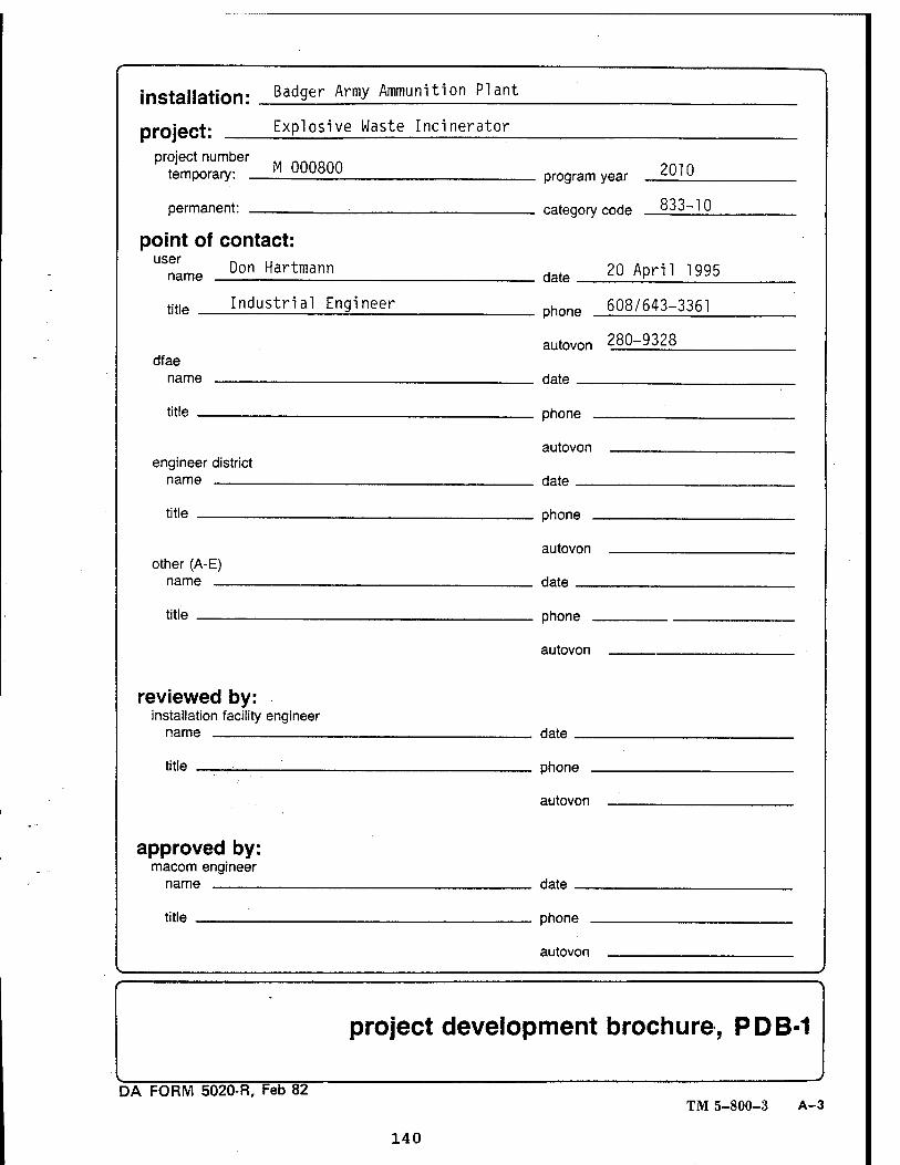
installation' Bad9er Army Ammunition Plant
project: Explosive Waste Incinerator
project number temporary: _
permanent: _
M 000800
point of contact: user
name Don Hartmann
title Industrial Engineer
dfae name
title
engineer district name
title
other (A-E) name
title
reviewed by: installation facility engineer
name
title
approved by: macom engineer
name
title
2010
fiatennrv rnrie 833-10
riate 20 April 1995
phone 608/643-3361
autovon 280-9328
riate
nhnne
autovon
riate
nhnne
autovon
Hate
nhnne
autovon
date
phone .
autovon
date
phone .
autovon
project development brochure, PDB-1
DA FORM 5020-R, Feb 82 TM 5-800-3 A-3
140
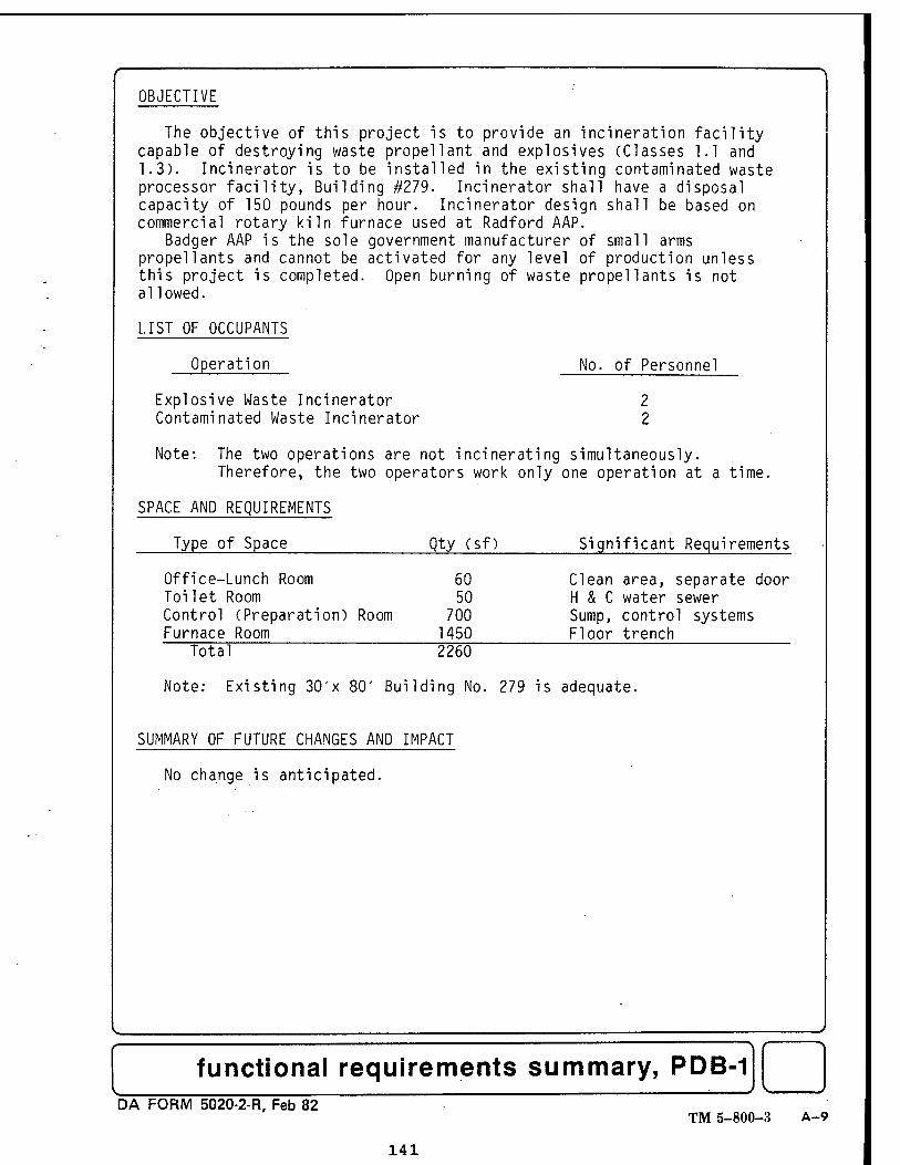
f~" ^ OBJECTIVE
The objective of this project is to provide an incineration facility capable of destroying waste propellant and explosives (Classes 1.1 and 1.3). Incinerator is to be installed in the existing contaminated waste processor facility, Building #279. Incinerator shall have a disposal capacity of 150 pounds per hour. Incinerator design shall be based on commercial rotary kiln furnace used at Radford AAP.
Badger AAP is the sole government manufacturer of small arms propel 1 ants and cannot be activated for any level of production unless this project is completed. Open burning of waste propellants is not allowed.
LIST OF OCCUPANTS
Operation No. of Personnel
Explosive Waste Incinerator 2 Contaminated Waste Incinerator 2
Note: The two operations are not incinerating simultaneously. Therefore, the two operators work only one operation at a time.
SPACE AND REQUIREMENTS
Type of Space Qty (sf) Significant Requirements
Office-Lunch Room 60 Clean area, separate door Toilet Room 50 H & C water sewer Control (Preparation) Room 700 Sump, control systems Furnace Room 1450 Floor trench
Total 2260
Note: Existing 30'x 80' Building No. 279 is adequate.
SUMMARY OF FUTURE CHANGES AND IMPACT
No change is anticipated.
————————)
functional requirements summary, PDB-1 DA FORM 5020-2-R, Feb 82
TM 5-800-3 A-9
141
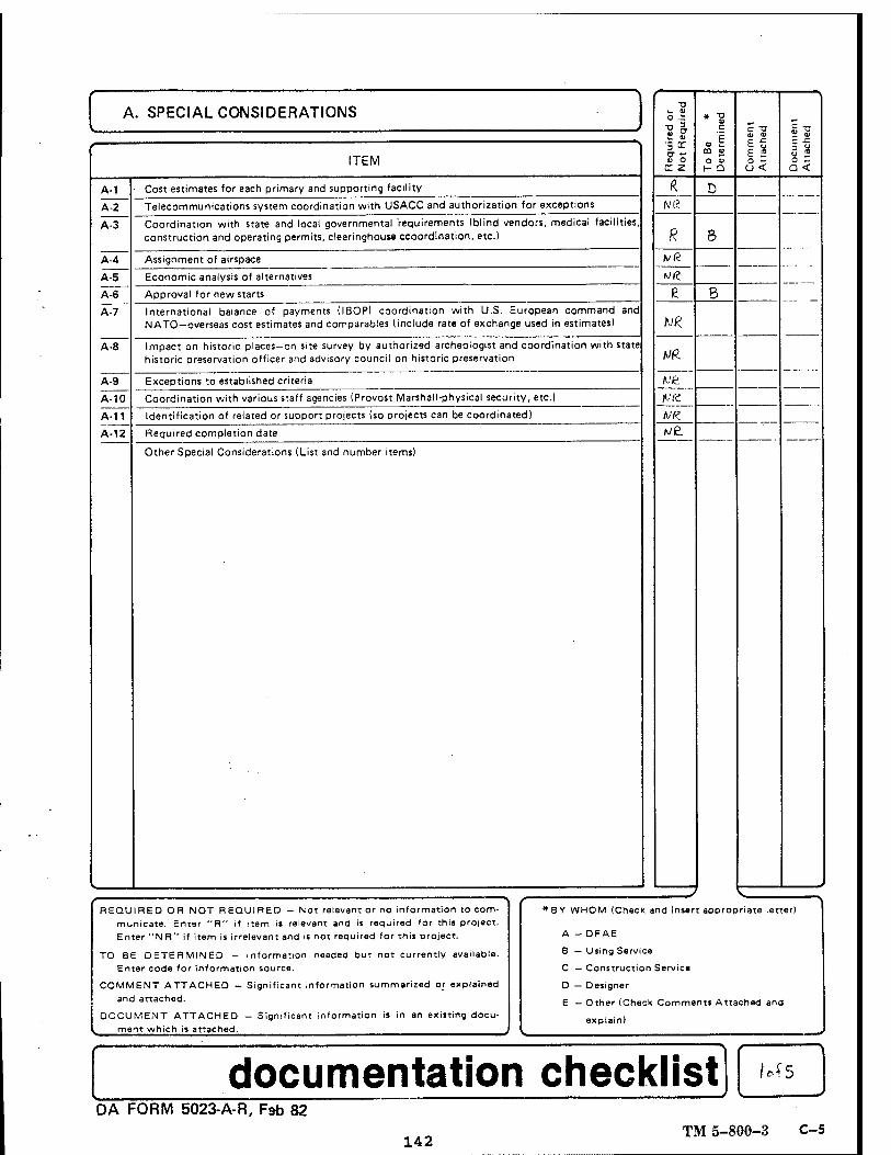
A. SPECIAL CONSIDERATIONS
A-1
A-2
A-3
A-4
Ä1T A-6
A-8
A-9
A-10
A-11
A-12
ITEM
Cost estimates for each primary and supporting facility
Telecommunications system coordination with USACC and authorization for exceptions
Coordination with state and local governmental requirements (blind vendors, medical facilities, construction and operating permits, clearinghouse ccoordination, etc.)
Assignment of airspace
Economic analysis of alternatives
Approval for new starts
International balance of payments (IBOP) coordination with U.S. European command and NATO—overseas cost estimates and comparables (include rate of exchange used in estimates)
Impact on historic places—on site survey by authorized archeologist and coordination with state historic preservation officer and advisory council on historic preservation
Exceptions to established criteria
Coordination with various staff agencies (Provost Marshall-physical security, etc.)
Identification of related or support projects (so projects can be coordinated)
Required completion date
Other Special Considerations (List and number items)
o .i
4) O rr z
rvß
R
hiR.
VfL
Mt
MK /ve.
O 1» h- Q
8
c -a e" £ 2 c3<
E^
O Z Q <
REQUIRED OR NOT REQUIRED - Not relevant or no information to com- municate. Enter "R" if item i* relevant and is required for this project. Enter "NR" if item is irrelevant and is not required for this project.
TO BE DETERMINED — Information needed but not currently available. Enter code for information source.
COMMENT ATTACHED — Significant information summarized or explained and attached.
DOCUMENT ATTACHED - Significant information is in an existing docu- ment which is attached.
f— *BY WHOM (Check and insert appropriate letter)
A - DFAE
B — Using Service
C — Construction Service
D — Designer
E - Other (Check Comments Attached and
explain) \
documentation checklist -
M5
DA FORM 5023-A-R, Fab 82
142 TM 5-800-3 C-5
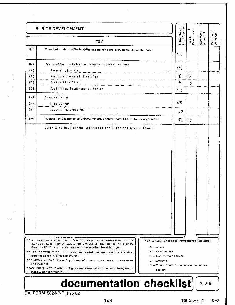
B. SITE DEVELOPMENT
B-2
(A)
(B)
(0)
ITEM
Consultation with the District Office to determine and evaluate flood plain hazards
Preparation, submission, and/or approval of new
General Site Plan
Annotated General Site Plan
0) O rr 2
f:H
tilt
O 0> r- Q
c "a p ^ E2 3<
E^
a <
B-3
_(Ai (B)
8-4
Sketch Site Plan
Facilities Requirements Sketch we Preparation of
Site Survey
Subsoil information
Approval by Department of Defense Explosive Safety Board (DDES8) for Safety Site Plan
Other Site Development Considerations (List and number items)
I REQUIRED OR NOT REQUIRED — Not relevant or no information to com-
municate. Enter "R" if item is relevant and is required for this project. Enter "NR" if item is irrelevant and is not required for this project.
TO BE DETERMINED — Information needed but not currently available. Enter code for information source.
COMMENT ATTACHED — Significant information summarized or explained and attached.
DOCUMENT ATTACHED — Significant information is in an existing docu- ment which is attached.
s-~ *BY WHOM (Check and insert appropriate letter)
A - OFAE
B — Using Service
C — Construction Service
D — Designer
E — Other (Check Comments Attached and
explain) s„
documentation checklist DA FORM 5023-B-R, Feb 82
143 TM 5-800-3 C-7
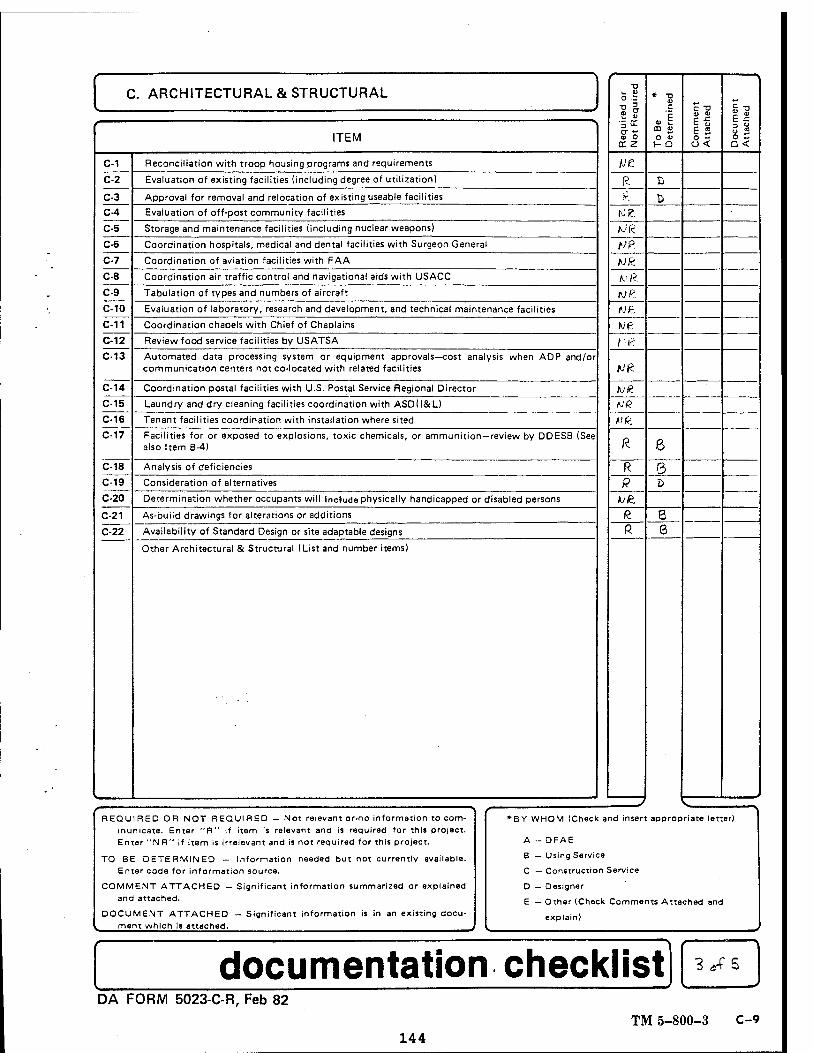
C. ARCHITECTURAL & STRUCTURAL
C-1
C-2
C-3
C-4
C-5
C-6
C-7
C-8
C-9
C-10
C-11
C-12
C-13
C-14
C-15
C-16
C-17
C-18
C-19
C-20
C-21
C-22
ITEM
Reconciliation with troop housing programs and requirements
Evaluation of existing facilities (including degree of utilization)
Approval for removal and relocation of existing useable facilities
Evaluation of off-post community facilities
Storage and maintenance facilities (including nuclear weapons)
Coordination hospitals, medical and dental facilities with Surgeon General
Coordination of aviation facilities with FAA
Coordination air traffic control and navigational aids with USACC
Tabulation of types and numbers of aircraft
Evaluation of laboratory, research and development, and technical maintenance facilities
Coordination chapels with Chief of Chaplains
Review food service facilities by USATSA
Automated data processing system or equipment approvals—cost analysis when ADP and/or communication centers not co-located with related facilities
Coordination postal facilities with U.S. Postal Service Regional Director
Laundry and dry cleaning facilities coordination with ASDll&L)
Tenant facilities coordination with installation where sited
Facilities for or exposed to explosions, toxic chemicals, or ammunition—review by DDESB (See also Item B-4)
Analysis of deficiencies
Consideration of alternatives
Determination whether occupants will Include physically handicapped or disabled persons
As-build drawings for alterations or additions
Availability of Standard Design or site adaptable designs
Other Architectural & Structural (List and number items)
- R
equired o
r N
ot
Required
* X) c
• 1 CD u O V
1- Q
c -o
%" E 2 8< D
ocu
ment
Att
ach
ed
... -.-
..„■.-.—
,—■
lit R B
K t> toe. hi«
HP. hJk.
Kfi.
fjP.
CJft
we t'K
rU£
Ml? M(Z
fJQ.
R 6 R 5 R D
^e. R. 6 ft 6
REQUIRED OR NOT REQUIRED — Not relevant or.no information to com- municate. Enter "R" if item is relevant and is required for this project. Enter "NR" if item is irrelevant and is not required for this project.
TO BE DETERMINED — Information needed but not currently available. Enter code for information source.
COMMENT ATTACHED — Significant information summarized or explained and attached.
DOCUMENT ATTACHED — Significant information is in an existing docu- ment which is attached.
*— *BY WHOM (Check and insert appropriate letter)
A - DFAE
B — Using Service
C — Construction Service
D — Designer
E — Other (Check Comments Attached and
explain)
documentation checklist 3*f 5
DA FORM 5023-C-R, Feb 82 TM 5-800-3 C-9
144
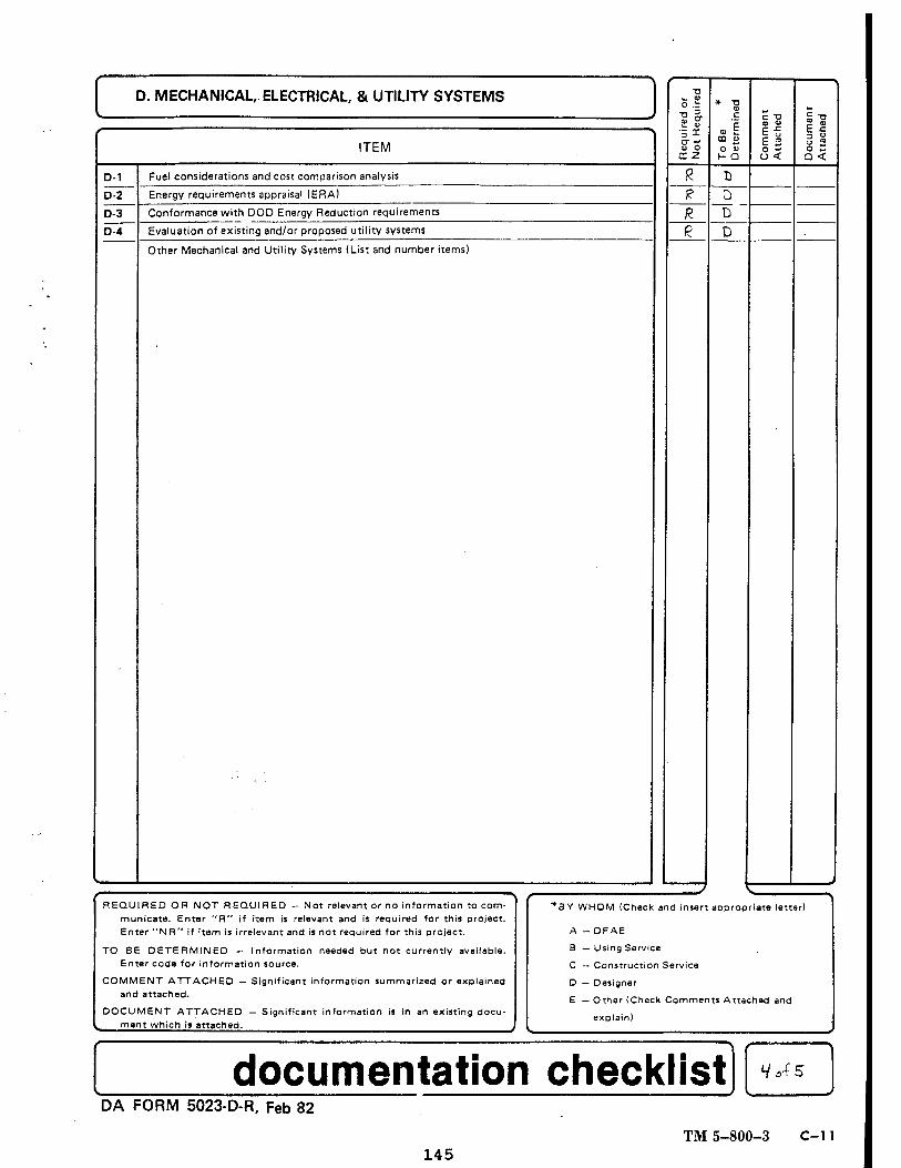
D. MECHANICAL, ELECTRICAL, & UTILITY SYSTEMS
ITEM
D-1
D-2
D-3
D-4
Fuel considerations and cost comparison analysis
Energy requirements appraisal (ERA)
Conformance with DOD Energy Reduction requirements
Evaluation of existing and/or proposed utility systems
Other Mechanical and Utility Systems (List and number items)
°" ~ 0> O rr z
* -o c
.1 CD ju
O V h- a
_D D
I « E i2 a <
REQUIRED OR NOT REQUIRED - Not ralevant or no information to com- municate. Enter "R" if item is relevant and is required for this project. Enter "MR" if item is irrelevant and is not required for this project.
TO BE DETERMINED — Information needed but not currently available. Enter code for information source.
COMMENT ATTACHED - and attached.
DOCUMENT ATTACHED ment which is attached.
Significant information summarized or explained
— Significant information is in an existing docu-
*SY WHOM (Check and insert appropriate letter)
A - DFAE
B — Using Service
C — Construction Service
D — Designer
E — Other (Check Comments Attached and
explain)
documentation checklist HcAS
DA FORM 5023-D-R, Feb 82
TM 5-800-3 C-l1 145
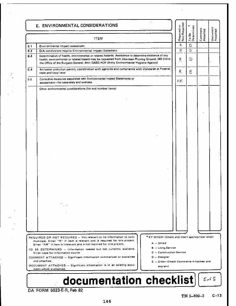
E. ENVIRONMENTAL CONSIDERATIONS
ITEM
E-1
IT E-3
Environmental impact assessment
E-4
E-5
El A conclusions require Environmental Impact Statement
Determination of health, environmental or related hazards. Assistance to determine existence of any health, environmental or related hazard may be requested from Aberdeen Proving Ground, MD 21010, the Office of the Surgeon General, Attn: DASG-HCH (Army Environmental Hygiene Agency)
Air/water pollution permit, coordination with agencies and compliance with standards at Federal, state and local level
Corrective measures associated with Environmental Impact Statements or assessment—list separately and evaluate.
Other environmental considerations (list and number items)
o .i
? &
<u O
X z
Nft
* -3 C
.1 DO «
O u r- Q
D
D
c -o
E 2 <3< Q <
REQUIRED OR NOT REQUIRED — Not relevant or no information to com- municate. Enter "R" if item is relevant and is required for this project. Enter "NR" if item is irrelevant and is not required for this project.
TO BE DETERMINED - Information needed but not currently available. Enter code for information source.
COMMENT ATTACHED — Significant information summarized or explained and attached.
DOCUMENT ATTACHED - Significant information i« in an existing docu- ment which is attached.
1—■
*BY WHOM (Check and insert appropriate letter)
A - DFAE
B — Using Service
C — Construction Service
D — Designer
E — Other (Cheek Comments Attached and
>- explain)
documentation checklist 5Vf S
DA FORM 5023-E-R, Feb 82 TM 5-800-3 C-13
146
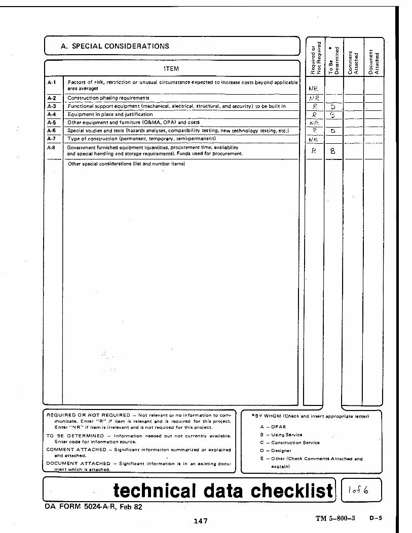
A. SPECIAL CONSIDERATIONS
A-1
A-2
AT" A-4
AT" A-6
A-7
A-8
ITEM
Factors of risk, restriction or unusual circumstance expected to increase costs beyond applicable area averages
Construction phasing requirements
Functional support equipment (mechanical, electrical, structural, and security) to be built in
Equipment in place and justification
Other equipment and furniture (O&MA, OPA) and costs
Special studies and tests (hazards analyses, compatibility testing, new technology testing, etc.
Type of construction (permanent, temporary, semi-permanent)
Government furnished equipment (quantities, procurement time, availability and special handling and storage requirements). Funds used for procurement.
Other special considerations (list and number items)
o ±
•I ■5OC
°" X <u o tr z
Vfi
Mß
ß wr>
HJfc
R
0) w CD O
O 1> H a
c -a
e 2 ££ o m
o Z Q <
&
REQUIRED OR NOT REQUIRED - Not relevant or no information to com- municate. Enter "R" if item is relevant and is required for this project. Enter "N R" if item is irrelevant and is not required for this project.
TO BE DETERMINED — Information needed but not currently available. Enter code for information source.
COMMENT ATTACHED — Significant information summarized or explained and attached.
DOCUMENT ATTACHED — Significant information is in an existing docu- ment which is attached.
*BY WHOM (Check and insert appropriate letter) —1
A -DFAE
B — Using Service
C — Construction Service
D — Designer
E —Other (Check Comments Attached and
explain)
data checklist IcU
DA FORM 5024-A-R, Feb 82
147 TM 5-800-3 D-5
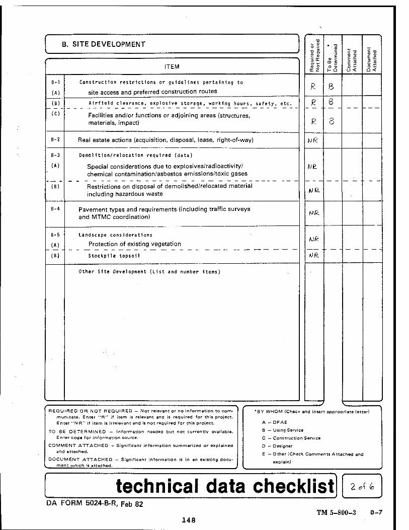
B. SITE DEVELOPMENT
Re
qu
ire
d o
r N
ot
Required
• -X) o> c
0,1 O 4>
ID 11
i» £ 2
Docu
ment
Attach
ed
f ITEM
B-1
(A)
Construction restrictions or guidelines pertaining to
site access and preferred construction routes R 8
(B) Airfield clearance, explosive storage, working hours, safety, etc. J? 6 (C) Facilities and/or functions or adjoining areas (structures,
materials, impact) P- 8
B-2 Real estate actions (acquisition, disposal, lease, right-of-way) fjß
B-3
(A)
(B)
Demolition/relocation required (data)
Special considerations due to explosives/radioactivity/ chemical contamination/asbestos emissions/toxic gases
Restrictions on disposal of demolished/relocated material including hazardous waste
B-4 Pavement types and requirements (including traffic surveys and MTMC coordination)
Mß.
B-5
(A)_
(B)
Landscape considerations
Protection of existing vegetation
Stockpile topsoll
Other Site Development (List and number items)
REQUIRED OR NOT REQUIRED - Not relevant or no information to com- municate. Enter "R" if item is relevant and is required for this project. Enter "NR" if item is irrelevant and is not required for this project.
TO BE DETERMINED — Information needed but not currently available. Enter code for information source.
COMMENT ATTACHED — Significant information summarized or explained and attached.
DOCUMENT ATTACHED — Significant information is in an existing docu- ment wnich is attached.
•8Y WHOM (Check and insert appropriate letter)
A - DFAE
B — Using Service
C — Construction Service
D — Designer
E — Other (Check Comments Attached and
explain)
technical data checklist DA FORM 5024-B-R, Feb 82
TM 5-800-3 D-7 148
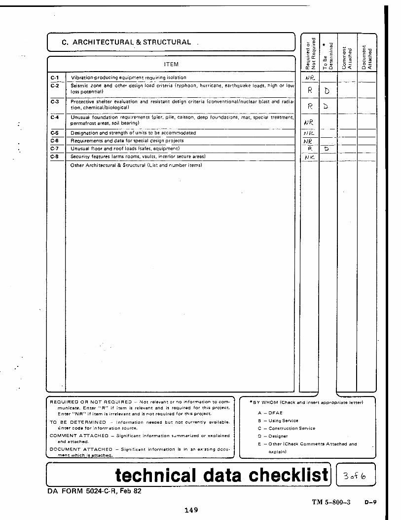
C. ARCHITECTURAL & STRUCTURAL
C-1
C-3
C-4
C-5
cöT
ITEM
Vibration-producing equipment requiring isolation
Seismic zone and other design load criteria (typhoon, hurricane, earthquake loads, high or low loss potential)
Protective shelter evaluation and resistant design criteria (conventional/nuclear blast and radia- tion, chemical/biological)
Unusual foundation requirements (pier, pile, caisson, deep foundations, mat, special treatment permafrost areas, soil bearing)
Designation and strength of units to be accommodated
Requirements and data for special design projects
Unusual floor and roof loads (safes, equipment)
Security features (arms rooms, vaults, interior secure areas)
Other Architectural & Structural (List and number items)
■a i_ 0) o .i
11 ■5 er O" X 9j O
cr z
UR.
R
R
VR. Ml't
w.e a
AJ£
o a» h- Q
h
<ü tu
I « e s O w Q <
REQUIRED OR NOT REQUIRED - Not relevant or no information to com- municate. Enter "R" if item is relevant and is required for this project. Enter "NR" if item is irrelevant and is not required for this project.
TO BE DETERMINED - Information needed but not currently available. Enter code for information source.
COMMENT ATTACHED — Significant information summarized or explained and attached.
DOCUMENT ATTACHED — Significant information is in an existing docu- ment which is attached.
f *BY WHOM (Check and insert appropriate letter)
A - DFAE
B — Using Service
C — Construction Service
D — Designer
E — Other (Check Comments Attached and
explain)
data checklist ZJ<o
DA FORM 5024-C-R, Feb 82
TM 5-800-3 D-9 149
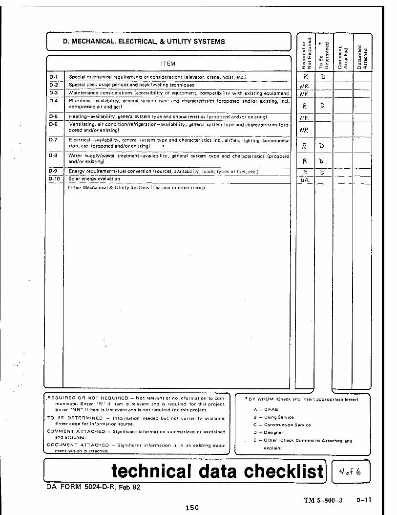
D. MECHANICAL, ELECTRICAL, & UTILITY SYSTEMS
D-1
D-2
D-3
D-4
D-5 D-6
D-7
0-8
0-9
D-10
ITEM
Special mechanical requirements or considerations (elevator, crane, hoist, etc.)
Special peak usage periods and peak leveling techniques
Maintenance considerations (accessibility of equipment, compatibility with existing equipment)
Plumbing—availability, general system type and characteristics (proposed and/or existing, incl. compressed air and gas)
Heating—availability, general system type and characteristics (proposed and/or existing)
Ventilating, air condition/refrigeration—availability, general system type and characteristics (pro- posed and/or existing)
Electrical—availability, general system type and characteristics incl. airfield lighting, communica- tion, etc. (proposed and/or existing) •
Water supply/waste treatment—availability, general system type and characteristics (proposed and/or existing)
Energy requirements/fuel conversion (sources, availability, loads, types of fuel, etc.)
Solar energy evaluation
Other Mechanical & Utility Systems (List and number items)
o .t ?& °" X tu O
rr z
fc D UR. Nfc
ft D
fJt.
V£
R. D
R b
R D A; ft.
CO <x> o <u H Q
c "o
6 2 8<
el
a <
.REQUIRED OR NOT REQUIRED - Not relevant or no information to com- municate. Enter "R" if item is relevant and is required for this project. Enter "NR" if item is irrelevant and is not required for this project.
TO BE DETERMINED — Information needed but not currently available. Enter code for information source.
COMMENT ATTACHED — Significant information summarized or explained and attached.
DOCUMENT ATTACHED — Significant information is in an existing docu- ment which is attached.
t *BY WHOM (Check and insert appropriate letter)
A - DFAE
B — Using Service
C — Construction Service
D — Designer
E — Other (Check Co
explain)
mmen ts Attached and
.,
DA FORM 5024-D-R, Feb 82
TM 5-800-3 D-11 150
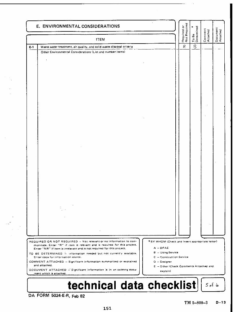
E. ENVIRONMENTAL CONSIDERATIONS
ITEM
E-1 Waste water treatment, air quality, and solid waste disposal criteria
Other Environmental Considerations (List and number items)
<u O cr z
R
CO 0)
O <U
R
C T3
£ 2 <3<
Er
o — Q <
REQUIRED OR NOT REQUIRED — Not relevant or no information to com- municate. Enter "R" if item is relevant and is required for this project. Enter "NR" if item is irrelevant and is not required for this project.
TO BE DETERMINED — Information needed but not currently available. Enter code for information source.
COMMENT ATTACHED — Significant information summarized or explained and attached.
DOCUMENT ATTACHED -Significant information is in an existing docu- ment which is attached.
*SY WHOM (Check and insert appropriate letter)
A - DFAE
8 — Using Service
C — Construction Service
D — Designer
E — Other (Check Comments Attached
explain)
and
technical data checklist 5 A (o
DA FORM 5024-E-R, Feb 82
TM 5-800-3 D-13 151
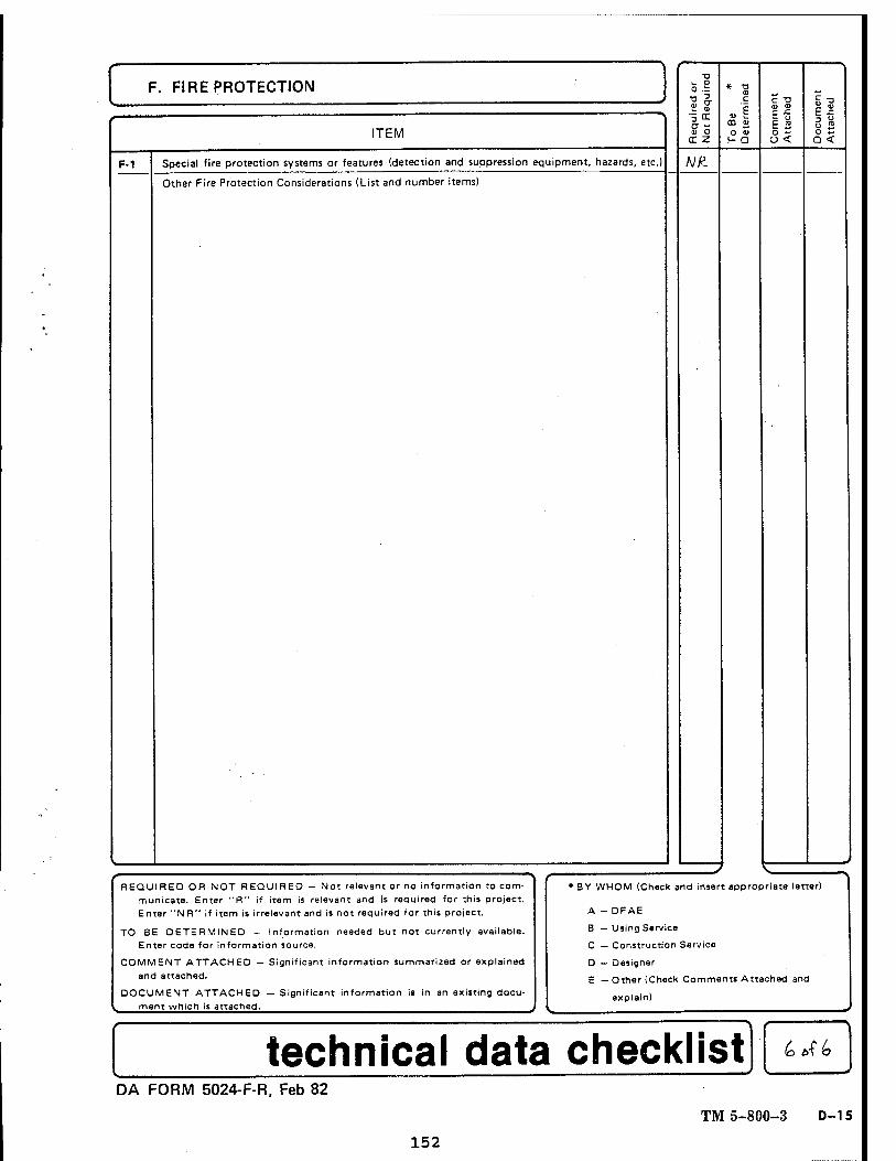
F. FIRE PROTECTION
ITEM
F-1 Special fire protection systems or features (detection and suppression equipment, hazards, etc.)
Other Fire Protection Considerations (List and number items)
"O
o .:=
V* •5 cc
tr z
NR.
CO 0) O 0)
H- Q
C T3
e s 3< o S
a <
REQUIRED OR NOT REQUIRED - Not relevant or no information to com- municate. Enter "R" if item is relevant and is required for this project. Enter "N R" if item is irrelevant and is not required for this project.
TO BE DETERMINED - Information needed but not currently available. Enter code for information source.
COMMENT ATTACHED — Significant information summarized or explained and attached.
DOCUMENT ATTACHED — Significant information is in an existing docu- ment which is attached.
♦BY WHOM (Check and insert appropriate letter)
A - DFAE
B — Using Service
C — Construction Service
D — Designer
E — Other (Check Comments Attached
explain)
and
-
technical data checklist DA FORM 5024-F-R, Feb 82
TM 5-800-3 D-15
152
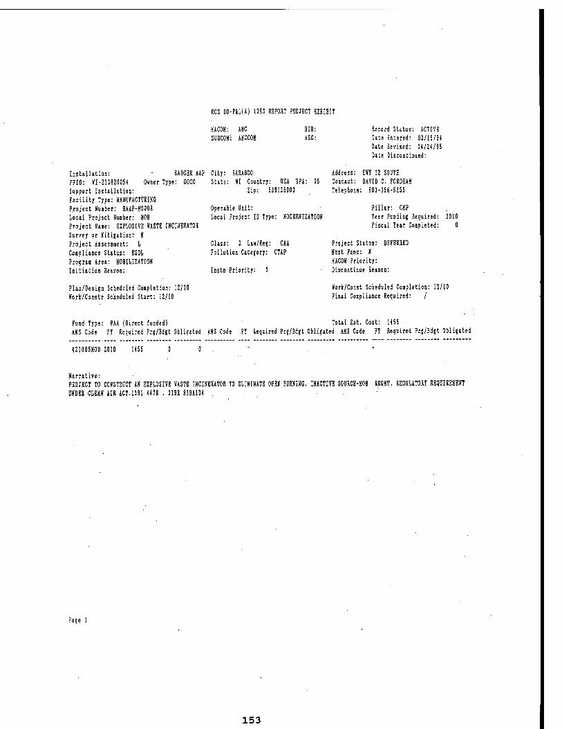
RCS DD-PiLlAl 1383 REPORT PROJECT EXHIBIT
KACOH: AHC SUBCOM: AKCCOK
SSB: ASG:
Record Status: ACTIVE One Entered: 03/15/9* Date Reused: 0*/24/95 Date Discontinued:
[0st2.lla.tiaa: BADGER AAP City: BARABOO Address: HVT 12 SOOTH ??ID: YI-213820054 Owner Type: GOCO Support Installation: Facility Type: HANUFACTURIHG Project Umber: BAAP-H0008 Local Project Nuaber: HOB Project Dane: EXPLOSIVE »ASTE mCIHBRATOR Sur7ey or tfitigationr U Project Assessient: L Coipliance Status: BSDL Prograa Area: • KOBILIUTIOH Initiation Reason:
State: »I Country: OS* SPA: 05 Zip: 539135000
Contact: DAVID C. P0RDHAH Telephone: 603-355-5255
Operable Unit: Local Project ID Type: HODBRKIZATION
Pillar: CUP Tear Funding Required: Fiscal Tear Coapleted:
2010 0
Class: 3 Lav/Re?: CAA Pollution Category: CTAP
Instn Priority: 3
Project Status: DEFERRED tfust Fund: II HACOH Priority: Discontinue Reason:
Plan/Design Scheduled Coipletion: 12/10 Vorfc/Constr Scheduled Start: 12/10
Kork/Const Scheduled Coapletion: 12/10 Final Coipliance Required: /
Fund Type: PAA (Direct funded I AUS Code FT Required Prg/Bdgt Obligated AHS Code
Total Est. Cost: 1455 FT Required Prg/Bdgt Obligated AUS Code FT Required Prg/Bdgt Obligated
+21005MOD 2010 1455
Harratire: PROJECT TO CONSMCT AN EXPLOSIVE »ASTB IHCINBRATOR TO BLIHIXATB OPEH BURHIHG. INACTIVE SOURCE-SOB uTOi CLEA» AIR ACT.1391 «78 . 319E 81BA134 .
RSQKT. REGULATORT REQDIRESEMT
Pase
153
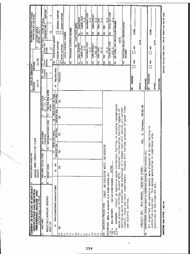
■s h- 0. QC
oft «n
*2
§8 ►- X ZO IU U.
i<~ UJ 111 « a O u. UJ
I t in 8 8
8° QC
to O tj 0
a * ^ 9- Z ^o
go u ca 3
5;o 8° o
o i- a
yY OS Z i
< UJ oc a. o UJ
<
3 I 3 s DD
ö
« a
g 3 g- 1 § ^ S 8 § U = oc
UJ
3 Z
UJ 00
z o at t-
< a lO O u
UJ
a. 3 a UJ
-0
1° UJ
i UI UJ u-
d V) UJ c —*
2
•0
UJ a>
3 Z OC O
UJ
H °°
Z O l- < y u. 1- Z UJ a
Ö UJ
UJ O O u
UJ a 0 u
i a.
5 o X r-
5
CO
1— 0 h- UJ 1- <
UJ X o QC 1- Z
Z o u CN
QC UJ
v> O u i o
to 0 U
0 oc a. 0
< Q
< n <*> >- a. * CM
5§i o u < 8
1 QC
8 Od tx.
a. O oc a.
< UJ QC
8d O ao <
So UJ
|o
8s CD 3 * vy
« °. 8^ < o
UI UJ u.
3
—. I- O to . < ■" LOS ^ u-i 0 5 ■* u- OJQ P "^ Q
§35 Uco
$ 3 ? z
z
D z
D 0
Z o in
ID
g i to o > UJ
I„ Z IX) i- to
CM O UJ — UQ
?5 IN a - cT en* V »Ö" ■o ■o
IN CN Ui >-
D
10 UJ >
D 0.
to cc 8« ca Q-QUI U_ o 3 z9 Q CO a to ■ So UJ o UJ u. O
CO u. U t— 5 <
CO
Q UJ UL UJ
< 9 UJ CTi
-J (^ < -v Z 0> o °
UJ UD ac DC t— <
QC CO QC UJ > u
J. ÜZ u.
3
z 0
I u ÜZ
-• u.
3
< z 0
CN s o oc
00 CN O 55 S 0 55
h-
UJ < UJ 5 5
a. Or— a p OU- UJ un I u a. u_ i- < Zc-T i O * Z.
Oui to < - UJ ,— *9
UJ > UJ
-a aj t/)
4-> tJ 11 a: 0
1« Q i (0 M- c c
c o a> •!- < ca
~ O QC H i«i-'" 0
2: K 0. 3
o x
< +J -Q O QJ 00
Z. C (D +J GO i- O CLi— (CJ c
c 10 E +■>
UJ Q S O nJ O u
O) u- c >, >, o
z o 1-
■rP(- c
I +J-r W C l/> 1 •!- O •i- T- +J •»-
CO 3:
01 ac < X X U (O Wl c UJ
ico z UJ
UJ Q
< 5
X < Z.
O «J w c U- 01
C i— -!->
Q -r- x:
1- -r- r— z 15 0. <
u o
■i- c .— x: o •!- aj O
O a.
3 3
< Üg a. >>T- S +J j-> ai
CU
a. _ UJ o at a.
■r- UJ -M TJ CU C Qi i— S- <a 3 O. CO
z a. O •i- CU -E i— O T- o d t- 1— O C ■!-> U
>— -o ~"
N, 3 o < <
^ -O E X ^ UJ c aj a 0 z 5 UJ h- 2: 1- -r- C i— fl> "+- u
E 3> Q I i—i O C i— . 0 •^ s: O C_) +J +-> CO T- 3 c 5 <
z (D o E 3 1- 3
■5 TJ •<- 5 <U < 3 ai s- co j-> g to CU
Z 5- UJ c +J 0 O O XJ _-. ZZ < z 1— ■r- tO C QJ Ü Q. . ,
g S o O u
W7 < t/1 < o u c-r-n CO 0
1 '^4J t— < •Z. 3 en ro CO
^ 00
•1- c_> to t_ UJ < CC CM 3 uj m
UJ •O cu CL 01
OS < c UJ > cu > »t -S a;^ P o oo < u to <j\ to • s j SO \S < en Z CO CTI Zz
a. o « rd rv 0 1/1
3 CM -— 4J -3 c —' _J >; oc *ac .r UJ cu x cu <. C W "O a. ca 0 QJ O X H g > 4-> 0) E 1 a. +J J=
-' <n o.' UJ o S •!- c cu 3 3 Ifl 3T3 L. CO _ to +J . 0 2 <y 4->
■*: S E u >- Q z O" Z O O C T- co . UJ < J-" ui •— U >0 3 ro a <
U QC ■£ K Q. u cr 01 9 X < 4-> CD C U CU c S-
J! U -co
1— .Jf (U CO
UJ 2 s 3 ^= > -1— i_
< 00 0 J3 >r- _c: .z.
OS'S z . 1- C Dir— i— 0 SHS D Z
1 o Ä < ro C i— (O ^f C 1— c
OFD
EF
l IN
DU
S
SUR
E (
AR
700
-90 00
Q z o
o n- U T- cu u is .. r— -a CL o • . y r-P- O-l 0)
c £ <a T- s_ cj « 4-> 3 Q.TJ ■!-
0 2: CM
1 <
O CL . CO t- X to CU
a 0 0 c TJ -P-
•= c j-> tu c£ z E iy) JD rz > C-J
1& UJ UJ !— a c cu ro s- zz vi CO (O r-
UJ z
z O a.
p tj UJ —l o QC a.
■5 ■-• s- -P cu cr -k. 0 iyi cu tn V f_ vi ra +J
e => 4-> ^ ■!-> ■!->
-n c •!- it.
RR
ENT
OR B
AC
K
DE
NTI
FIC
ATI
ON
PR
EPA
RED
NES
S (A
MC
CO
M S
upp
z cc 03
s u
UJ b:
- a: »i s »u 0 UJ 1- CU J-> T- c ft Z u 0100 i. c O UJ 0 C 4-> 2 gf S s- -I- - 0 3 0. a. >,r— cu
.. < a CU J- s- cu Z £ UJ 4-» +J & r\ V) w TJ TJ S (0 cu cu c £ 3 TJ U. CO S 6 -6
u. UJ cc c-
g CO to 0
'— TJ to Z CU (U c
g &^° < !- O to u a. t. -r- ut +J >
I <S cl
< oo S UJ 5. I-. CM UJ M z «c < 3 UJ UJ
< CC ■z.
>- u z UI
y UJ a
UJ ^) 0 cc CL.
U d ja u "6 « *.* d> ^ .-• .— -« - E c 6 a. CO CN s
154
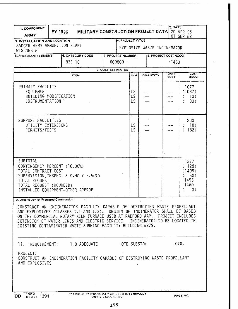
1. COMPONENT
ARMY FY 1996 MILITARY CONSTRUCTION PROJECT DATA
2. DATE
20 APR 95 01 SEP 82
3. INSTALLATION AND LOCATION
BADGER ARMY AMMUNITION PLANT WISCONSIN
4. PROJECT TITLE
EXPLOSIVE WASTE INCINERATOR
5. PROGRAM ELEMENT 6. CATEGORY CODE
833 10
7. PROJECT NUMBER
000800
8. PROJECT COST ($000)
•1460
9. COST ESTIMATES
ITEM U/M QUANTITY UNIT COST
COST (SOOO)
PRIMARY FACILITY EQUIPMENT BUILDING MODIFICATION INSTRUMENTATION '
LS LS LS
1077 (1037) ( 10) ( 30)
SUPPORT FACILITIES UTILITY EXTENSIONS PERMITS/TESTS
LS LS
200
( 18) ( 182)
SUBTOTAL CONTINGENCY PERCENT (10.00%) TOTAL CONTRACT COST SUPERVISION,INSPECT & OVHD ( 5.50%) TOTAL REQUEST TOTAL REQUEST (ROUNDED) INSTALLED EQUIPMENT-OTHER APPROP
1277 ( 128) (1405) ( 50) 1455 1460
( 0)
10. Detcripiioo of Propoted Construction
CONSTRUCT AN INCINERATION FACILITY CAPABLE OF DESTROYING WASTE PROPELLANT AND EXPLOSIVES (CLASSES 1.1 AND 1.3). DESIGN OF INCINERATOR SHALL BE BASED ON THE COMMERCIAL ROTARY KILN FURNACE USED AT RADFORD AAP. PROJECT INCLUDES EXTENSION OF WATER LINES AND ELECTRIC SERVICE. INCINERATOR TO BE LOCATED IN EXISTING CONTAMINATED WASTE BURNING FACILITY BUILDING #279.
11. REQUIREMENT: 1.8 ADEQUATE OTD SUBSTD: OTD.
PROJECT: CONSTRUCT AN INCINERATION FACILITY CAPABLE OF DESTROYING WASTE PROPELLANT AND EXPLOSIVES
DD ,FD°EcM76 1391
PREVIOUS EDITIONS MAY 6S USEO INTERN-ALLY UNTIL EXHAUSTED PAGE NO.
155
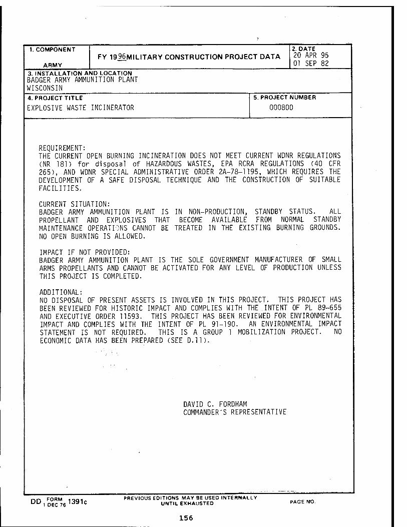
1. COMPONENT
ARMY FY 1996MILITARY CONSTRUCTION PROJECT DATA
2. DATE 20 APR 95 01 SEP 82
3. INSTALLATION AND LOCATION BADGER ARMY AMMUNITION PLANT WISCONSIN 4. PROJECT TITLE
EXPLOSIVE WASTE INCINERATOR
5. PROJECT NUMBER
000800
REQUIREMENT: THE CURRENT OPEN BURNING INCINERATION DOES NOT MEET CURRENT WDNR REGULATIONS CNR 181) for disposal of HAZARDOUS WASTES, EPA RCRA REGULATIONS (40 CFR 265), AND WDNR SPECIAL ADMINISTRATIVE ORDER 2A-78-1195, WHICH REQUIRES THE DEVELOPMENT OF A SAFE DISPOSAL TECHNIQUE AND THE CONSTRUCTION OF SUITABLE FACILITIES.
CURRENT SITUATION: BADGER ARMY AMMUNITION PLANT IS IN NON-PRODUCTION, STANDBY STATUS. ALL PROPELLANT AND EXPLOSIVES THAT BECOME AVAILABLE FROM NORMAL STANDBY MAINTENANCE OPERATIONS CANNOT BE TREATED IN THE EXISTING BURNING GROUNDS. NO OPEN BURNING IS ALLOWED.
IMPACT IF NOT PROVIDED: BADGER ARMY AMMUNITION PLANT IS THE SOLE GOVERNMENT MANUFACTURER OF SMALL ARMS PROPELLANTS AND CANNOT BE ACTIVATED FOR ANY LEVEL OF PRODUCTION UNLESS THIS PROJECT IS COMPLETED.
ADDITIONAL: NO DISPOSAL OF PRESENT ASSETS IS INVOLVED IN THIS PROJECT. THIS PROJECT HAS BEEN REVIEWED FOR HISTORIC IMPACT AND COMPLIES WITH THE INTENT OF PL 89-655 AND EXECUTIVE ORDER 11593. THIS PROJECT HAS BEEN REVIEWED FOR ENVIRONMENTAL IMPACT AND COMPLIES WITH THE INTENT OF PL 91-190. AN ENVIRONMENTAL IMPACT STATEMENT IS NOT REQUIRED. THIS IS A GROUP 1 MOBILIZATION PROJECT. NO ECONOMIC DATA HAS BEEN PREPARED (SEE D.ll).
DAVID C. FORDHAM COMMANDER'S REPRESENTATIVE
nn F0RM 1391c UU 1 DEC 76 lo:*lc
PREVIOUS EDITIONS MAY BE USED INTERNALLY UNTIL EXHAUSTED PAGE NO.
156
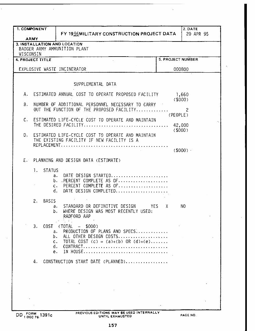
1. COMPONENT
ARMY FY 1996MILITARY CONSTRUCTION PROJECT DATA
2. DATE
20 APR 95
3. INSTALLATION AND LOCATION BADGER ARMY AMMUNITION PLANT WISCONSIN
4. PROJECT TITLE
EXPLOSIVE WASTE INCINERATOR
5. PROJECT NUMBER
000800
SUPPLEMENTAL DATA
A. ESTIMATED ANNUAL COST TO OPERATE PROPOSED FACILITY 1,660 ($000)
B. NUMBER OF ADDITIONAL PERSONNEL NECESSARY TO CARRY OUT THE FUNCTION OF THE PROPOSED FACILITY 2
(PEOPLE) C ESTIMATED LIFE-CYCLE COST TO OPERATE AND MAINTAIN
THE DESIRED FACILITY 42,000 ($000)
D. ESTIMATED LIFE-CYCLE COST TO OPERATE AND MAINTAIN THE EXISTING FACILITY IF NEW FACILITY IS A REPLACEMENT
($000)
E. PLANNING AND DESIGN DATA (ESTIMATE)
1. STATUS a. DATE DESIGN STARTED b. .PERCENT COMPLETE AS OF C. PERCENT COMPLETE AS OF d. DATE DESIGN COMPLETED
2. BASIS a. STANDARD OR DEFINITIVE DESIGN YES X NO b. WHERE DESIGN WAS MOST RECENTLY USED:
RADFORD AAP
3. COST (TOTAL - $000) a. PRODUCTION OF PLANS AND SPECS b. ALL OTHER DESIGN COSTS c. TOTAL COST (c) = (a)+(b) OR (d)+(e) d. CONTRACT e. IN HOUSE
4. CONSTRUCTION START DATE (PLANNED)
00,^13910 PREVIOUS EDITIONS MAY BE USED INTERNALLY UNTIL EXHAUSTED PAGE NO.
157
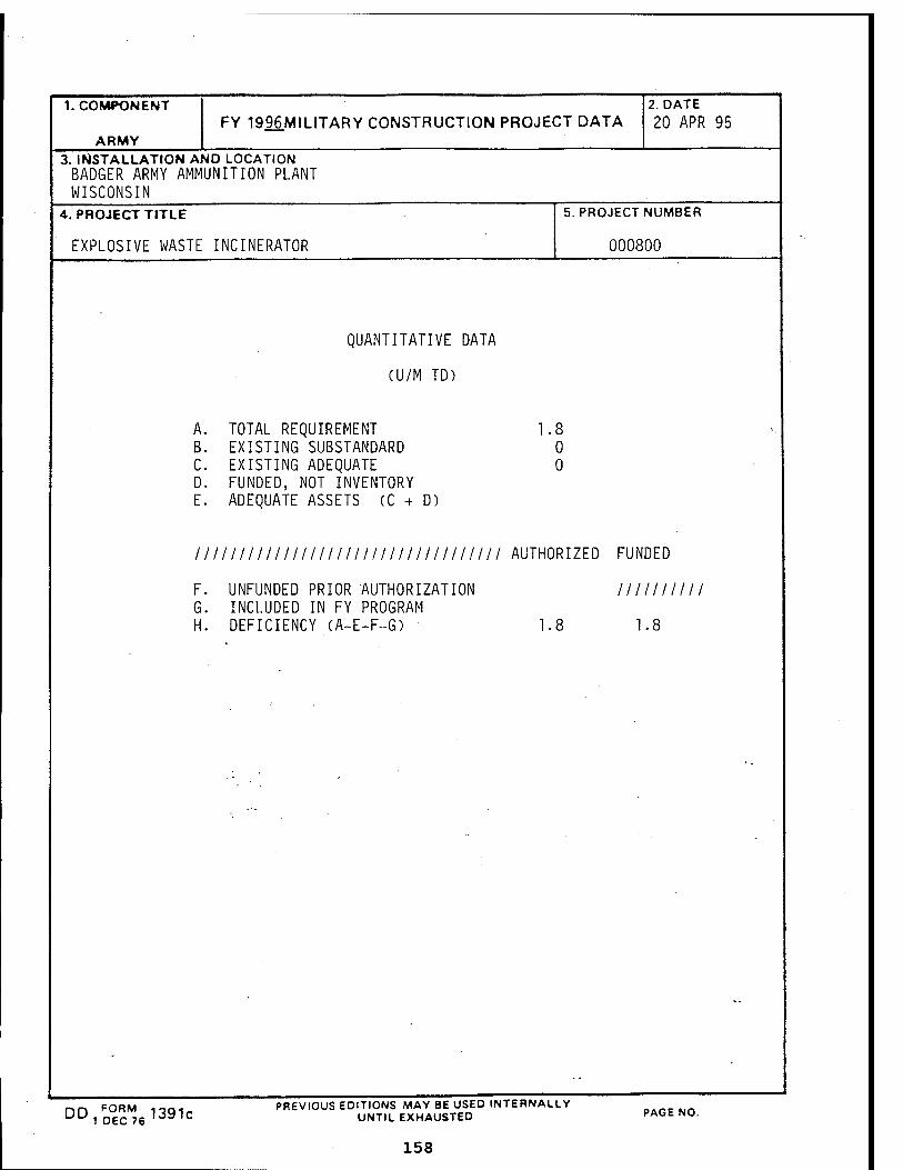
1. COMPONENT
ARMY FY 1996MILITARY CONSTRUCTION PROJECT DATA
2. DATE 20 APR 95
3. INSTALLATION AND LOCATION BADGER ARMY AMMUNITION PLANT WISCONSIN
4. PROJECT TITLE
EXPLOSIVE WASTE INCINERATOR
5. PROJECT NUMBER
000800
QUANTITATIVE DATA
(U/M TD)
A. TOTAL REQUIREMENT B. EXISTING SUBSTANDARD C. EXISTING ADEQUATE D. FUNDED, NOT INVENTORY E. ADEQUATE ASSETS (C + D)
1.8 0 0
11II III IIIIII III III III III IIII lllllI AUTHORIZED FUNDED
F. UNFUNDED PRIOR AUTHORIZATION IIIIIIII11 G. INCLUDED IN FY PROGRAM H. DEFICIENCY (A-E-F-G) 1.8 1.8
DO FORM 13Q1- UU 1 D6C76 loi,,c
PREVIOUS EDITIONS MAY BE USED INTERNALLY UNTIL EXHAUSTED
158
PAGE NO.
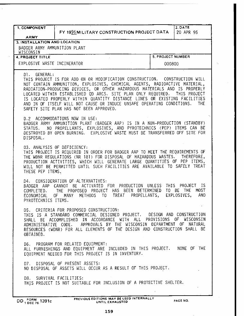
1. COMPONENT
ARMY FY 1996MILITARY CONSTRUCTION PROJECT DATA
2. DATE
20 APR 95
3. INSTALLATION AND LOCATION
BADGER ARMY AMMUNITION PLANT WISCONSIN
4. PROJECT TITLE
EXPLOSIVE WASTE INCINERATOR
5. PROJECT NUMBER
000800
Dl. GENERAL: THIS PROJECT IS FOR ADD ON OR MODIFICATION CONSTRUCTION. CONSTRUCTION WILL NOT CONTAIN AMMUNITION, EXPLOSIVES, CHEMICAL AGENTS, RADIOACTIVE MATERIAL, RADIATION-PRODUCING DEVICES, OR OTHER HAZARDOUS MATERIALS AND IS PROPERLY LOCATED WITHIN ESTABLISHED QD ARCS. SITE PLAN ONLY REQUIRED. THIS PROJECT IS LOCATED PROPERLY WITHIN QUANTITY DISTANCE LINES OR EXISTING FACILITIES AND IN OF ITSELF WILL NOT CAUSE OR INDUCE UNSAFE OPERATING CONDITIONS. THE SAFETY SITE PLAN HAS NOT BEEN APPROVED.
D.2 ACCOMMODATIONS NOW IN USE: BADGER ARMY AMMUNITION PLANT (BADGER AAP) IS IN A NON-PRODUCTION (STANDBY) STATUS. NO PROPELLANTS, EXPLOSIVES, AND PYROTECHNICS (PEP) ITEMS CAN BE DESTROYED BY OPEN BURNING. EXPLOSIVE WASTE MUST BE TRANSFERRED OFF SITE FOR DISPOSAL.
D3. ANALYSIS OF DEFICIENCY: THIS PROJECT IS REQUIRED IN ORDER FOR BADGER AAP TO MEET THE REQUIREMENTS OF THE WDNR REGULATIONS (NR 181) FOR DISPOSAL OF HAZARDOUS WASTES. THEREFORE, PRODUCTION ACTIVITIES, WHICH WILL GENERATE LARGE QUANTITIES OF PEP ITEMS, WILL NOT BE PERMITTED UNTIL SUCH FACILITIES ARE AVAILABLE TO SAFELY TREAT THESE PEP ITEMS.
D4. CONSIDERATION OF-ALTERNATIVES: BADGER AAP CANNOT BE ACTIVATED FOR PRODUCTION UNLESS THIS PROJECT IS COMPLETED. THE PROPOSED PROJECT HAS BEEN DETERMINED TO BE THE MOST ECONOMICAL OF MANY METHODS TO TREAT PROPELLANTS, EXPLOSIVES, AND PYROTECHNICS ITEMS.
D5. CRITERIA FOR PROPOSED CONSTRUCTION: THIS IS A STANDARD COMMERCIAL DESIGNED PROJECT. DESIGN AND CONSTRUCTION SHALL BE ACCOMPLISHED IN ACCORDANCE WITH ALL PROVISIONS OF WISCONSIN ADMINISTRATIVE CODE. APPROVALS BY THE WISCONSIN DEPARTMENT OF NATURAL RESOURCES (WDNR) FOR ALL ELEMENTS OF THE DESIGN AND CONSTRUCTION SHALL BE OBTAINED.
D6. PROGRAM FOR RELATED EQUIPMENT: ALL FURNISHINGS AND EQUIPMENT ARE INCLUDED IN THIS PROJECT. NONE OF THE EQUIPMENT NEEDED FOR THIS PROJECT IS IN INVENTORY.
D7. DISPOSAL OF PRESENT ASSETS: NO DISPOSAL OF ASSETS WILL OCCUR AS A RESULT OF THIS PROJECT.
D8. SURVIVAL FACILITIES: THIS PROJECT IS NOT SUITABLE FOR INCLUSION OF A PROTECTIVE SHELTER.
nn FORM ,-,Q, PREVIOUS EDITIONS MAY pe USED INTERNALLY B.ffNn DD1 DEC761391C UNTIL EXHAUSTED PAGE NO.
159
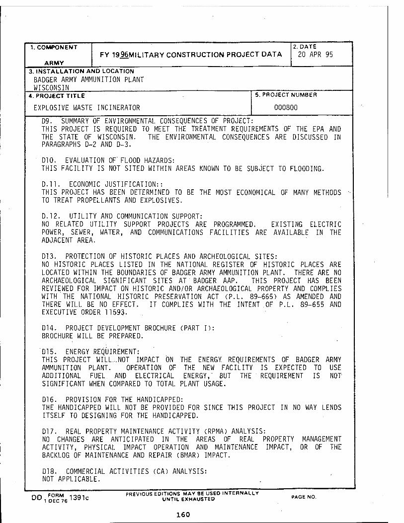
1. COMPONENT
ARMY FY 1996MILITARY CONSTRUCTION PROJECT DATA
2. DATE 20 APR 95
3. INSTALLATION AND LOCATION BADGER ARMY AMMUNITION PLANT WISCONSIN
4. PROJECT TITLE
EXPLOSIVE WASTE INCINERATOR
5. PROJECT NUMBER
000800
D9. SUMMARY OF ENVIRONMENTAL CONSEQUENCES OF PROJECT: THIS PROJECT IS REQUIRED TO MEET THE TREATMENT REQUIREMENTS OF THE EPA AND THE STATE OF WISCONSIN. THE ENVIRONMENTAL CONSEQUENCES ARE DISCUSSED IN PARAGRAPHS D-2 AND D-3.
D10. EVALUATION OF' FLOOD HAZARDS: THIS FACILITY IS NOT SITED WITHIN AREAS KNOWN TO BE SUBJECT TO FLOODING.
D.H. ECONOMIC JUSTIFICATION:: THIS PROJECT HAS BEEN DETERMINED TO TO TREAT PROPELLANTS AND EXPLOSIVES.
BE THE MOST ECONOMICAL OF MANY METHODS
D.12. UTILITY AND COMMUNICATION SUPPORT: NO RELATED UTILITY SUPPORT PROJECTS ARE PROGRAMMED. POWER, SEWER, WATER, AND COMMUNICATIONS FACILITIES ARE ADJACENT AREA.
EXISTING ELECTRIC AVAILABLE IN THE
D13. PROTECTION OF HISTORIC PLACES AND ARCHEOLOGICAL SITES: NO HISTORIC PLACES LISTED IN THE NATIONAL REGISTER OF HISTORIC PLACES ARE LOCATED WITHIN THE BOUNDARIES OF BADGER ARMY AMMUNITION PLANT. THERE ARE NO ARCHAEOLOGICAL SIGNIFICANT SITES AT BADGER AAP. THIS PROJECT HAS BEEN REVIEWED FOR IMPACT ON HISTORIC AND/OR ARCHAEOLOGICAL PROPERTY AND COMPLIES WITH THE NATIONAL HISTORIC PRESERVATION ACT CP.L. 89-665) AS AMENDED AND THERE WILL BE NO EFFECT. IT COMPLIES WITH THE INTENT OF P.L. 89-655 AND EXECUTIVE ORDER 11593.
D14. PROJECT DEVELOPMENT BROCHURE (PART I): BROCHURE WILL BE PREPARED.
D15. ENERGY REQUIREMENT: THIS PROJECT WILL..NOT IMPACT ON THE ENERGY REQUIREMENTS OF BADGER ARMY AMMUNITION PLANT. OPERATION OF THE NEW FACILITY IS EXPECTED TO USE ADDITIONAL FUEL AND ELECTRICAL ENERGY, BUT THE REQUIREMENT IS NOT- SIGNIFICANT WHEN COMPARED TO TOTAL PLANT USAGE.
D16. PROVISION FOR THE HANDICAPPED: THE HANDICAPPED WILL NOT BE PROVIDED FOR SINCE THIS PROJECT IN ITSELF TO DESIGNING FOR THE HANDICAPPED.
NO WAY LENDS
D17. REAL PROPERTY MAINTENANCE ACTIVITY CRPMA) ANALYSIS: NO CHANGES ARE ANTICIPATED IN THE AREAS OF REAL PROPERTY MANAGEMENT ACTIVITY, PHYSICAL IMPACT OPERATION AND MAINTENANCE IMPACT, OR OF THE BACKLOG OF MAINTENANCE AND REPAIR CBMAR) IMPACT.
D18. COMMERCIAL ACTIVITIES (CA) ANALYSIS: NOT APPLICABLE.
DD F0RM 1391c UU 1 DEC 76 •3 ,C
PREVIOUS EDITIONS MAY BE USED INTERNALLY UNTIL EXHAUSTED PAGE NO.
160
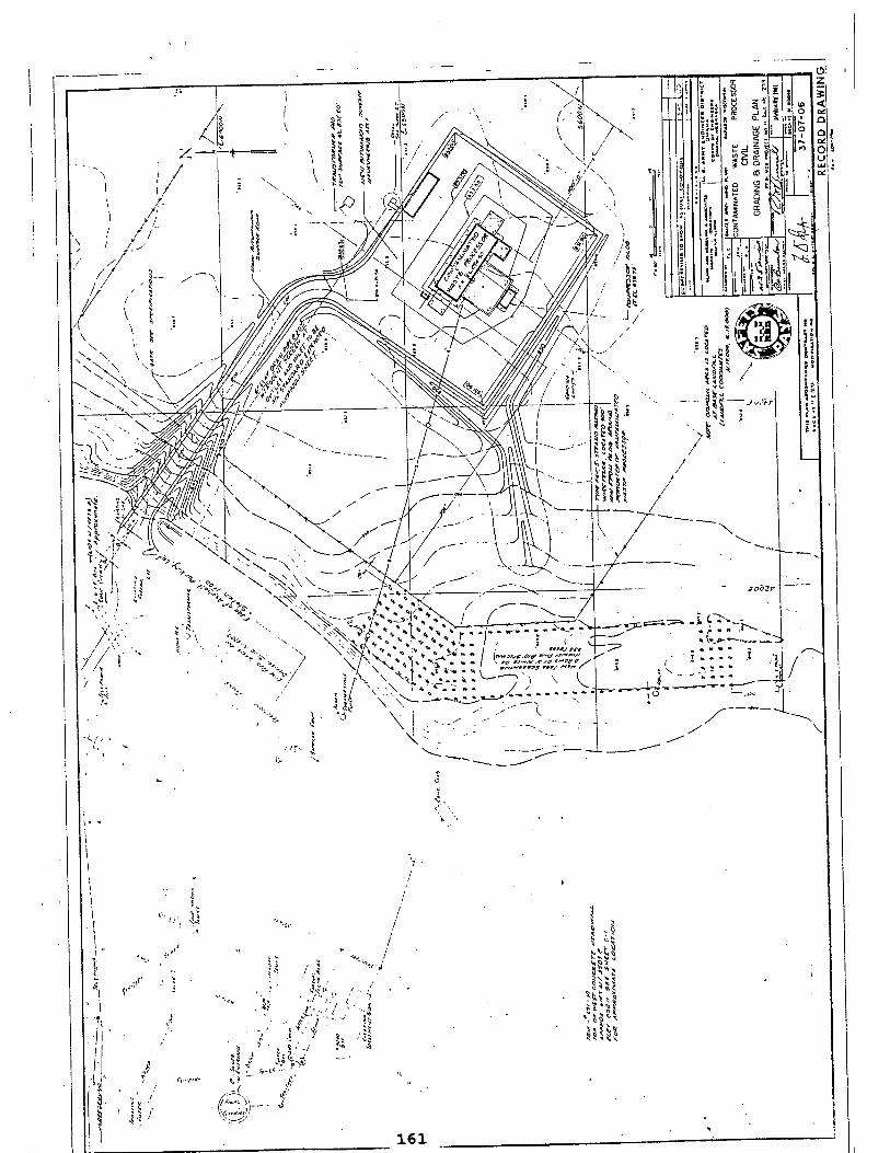
*, ,,
1 Ti.
j'i'
V. II
V/
W / .. , '" . 4? ■V ',
" ■*■' ; ■
" '>'' ■/■■■^ „ ,|J ■ .. > -
. 5 ■ -/' .'•8 A
«1 f *.« O--' »v* _<; v>/
r"1',)-- J '■■'—^
5 ^5
kip *
B Q S Cj B !? K ■« K V
161
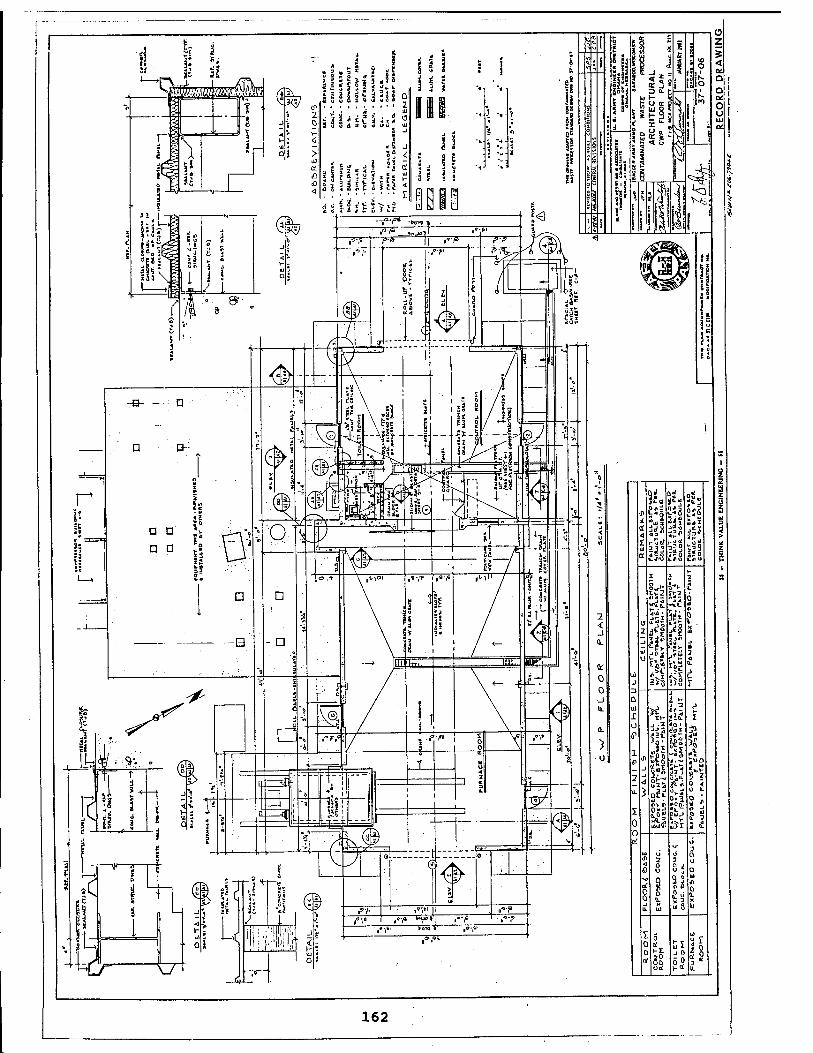
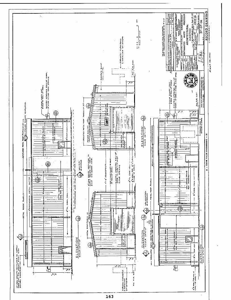
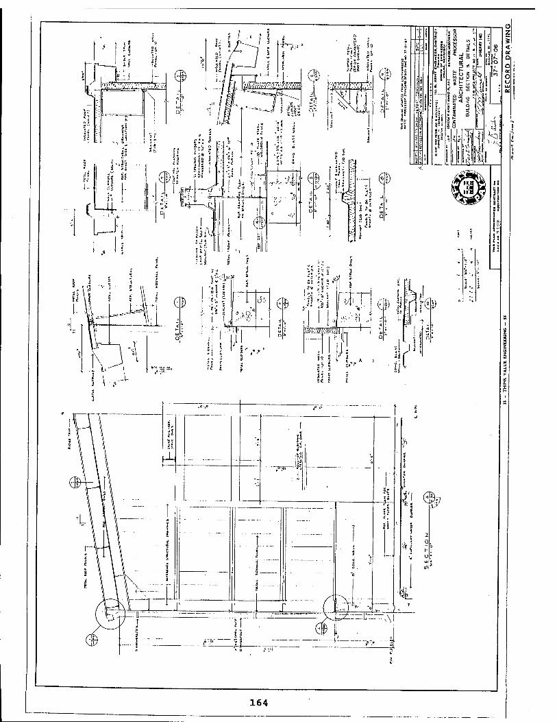
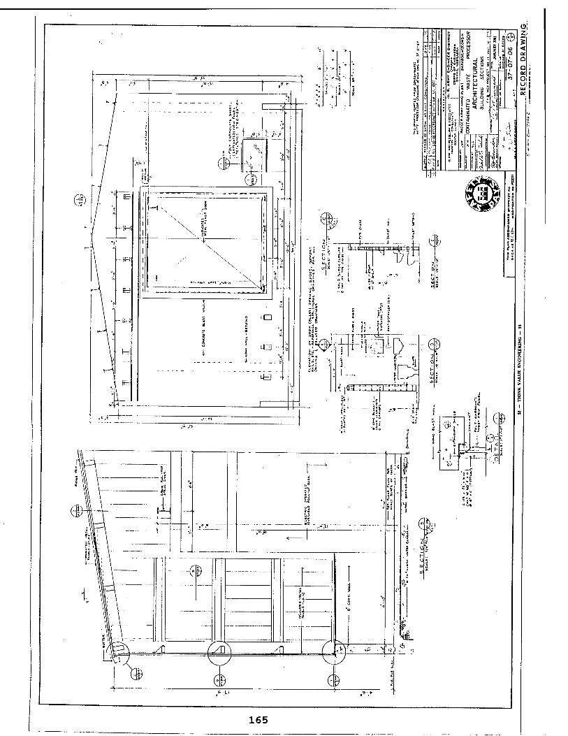
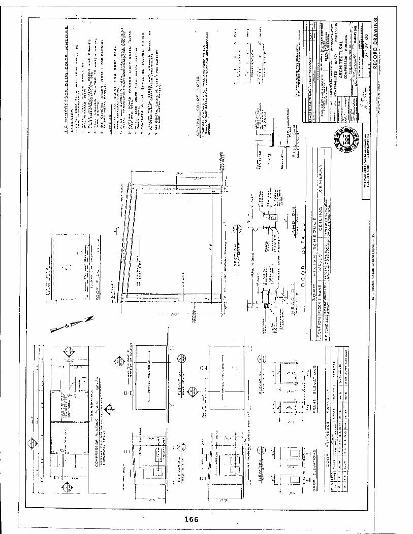
"yiE. <&
'' "0 ■' 1°.'
-:— 'o
Hi" ■^
ii.if« : .
Si S 2 i < i<
'*-'■> 2
:..i.. ... .. 1 u 2 O
■;
r . ■ J
* A: j - a: u 3
in o <
►-, "j\r- H a:
€
I i. v ■
0 .... u
..«■-.* i -* •,»
€>
hi-n i II 5 r* • i
II 1 • i i T i
3 LS _. ^ ^ . _
S ' i J
; •' ,J I« ..™a=
HI ! f! i 1 □
(U
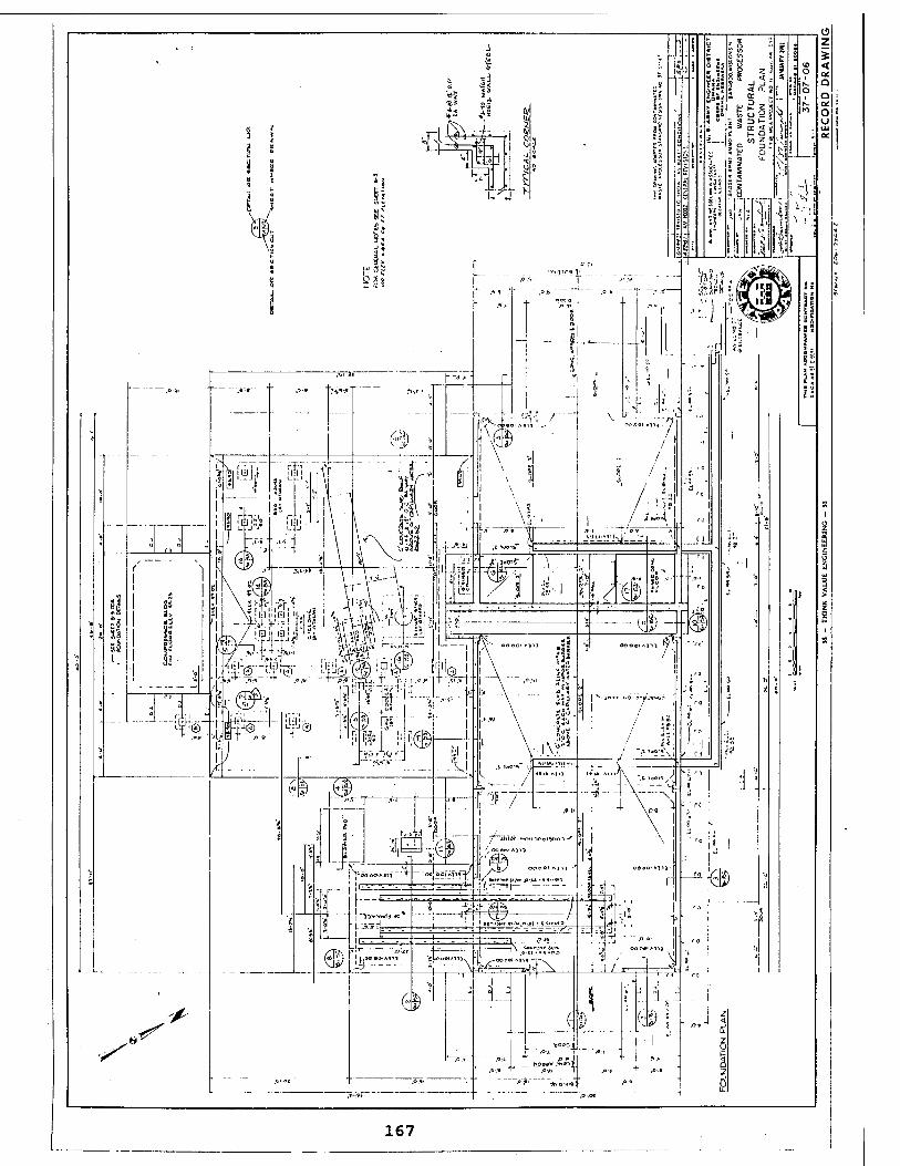
167
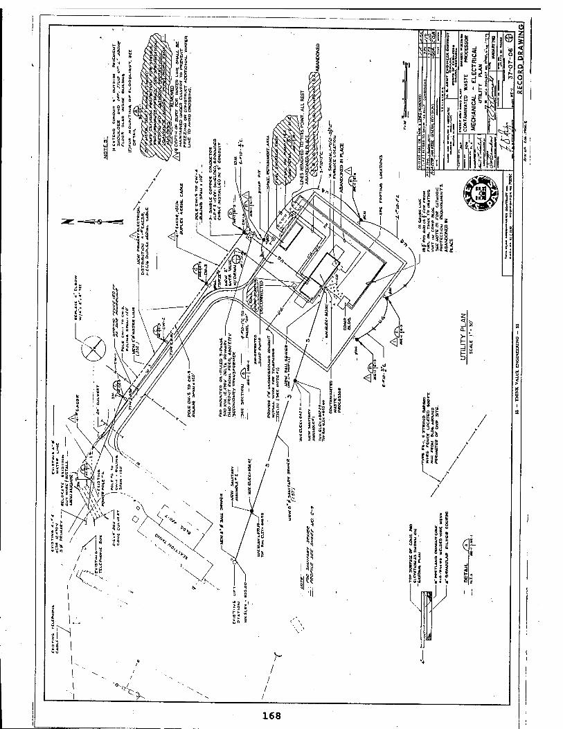
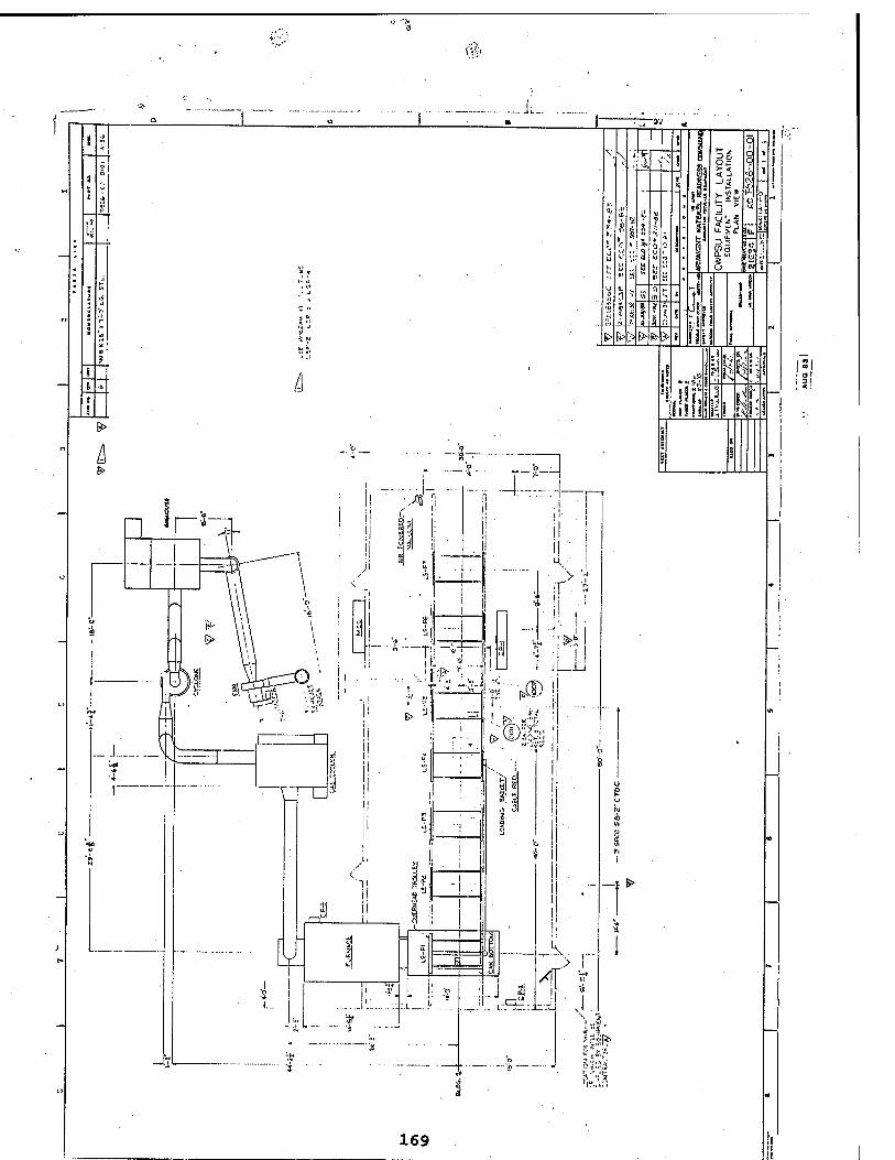
m
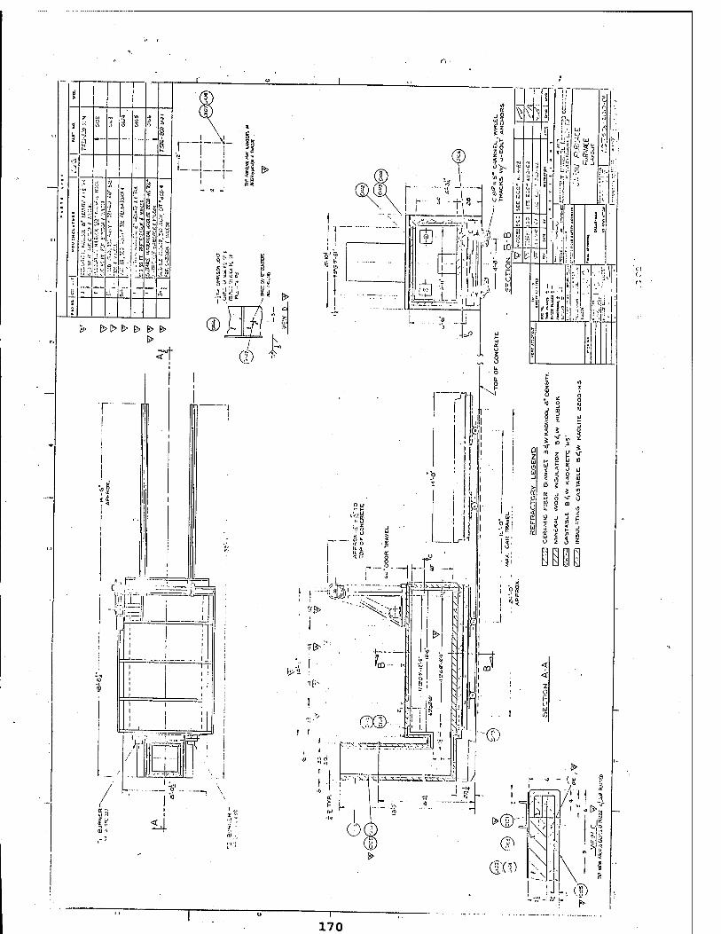
170
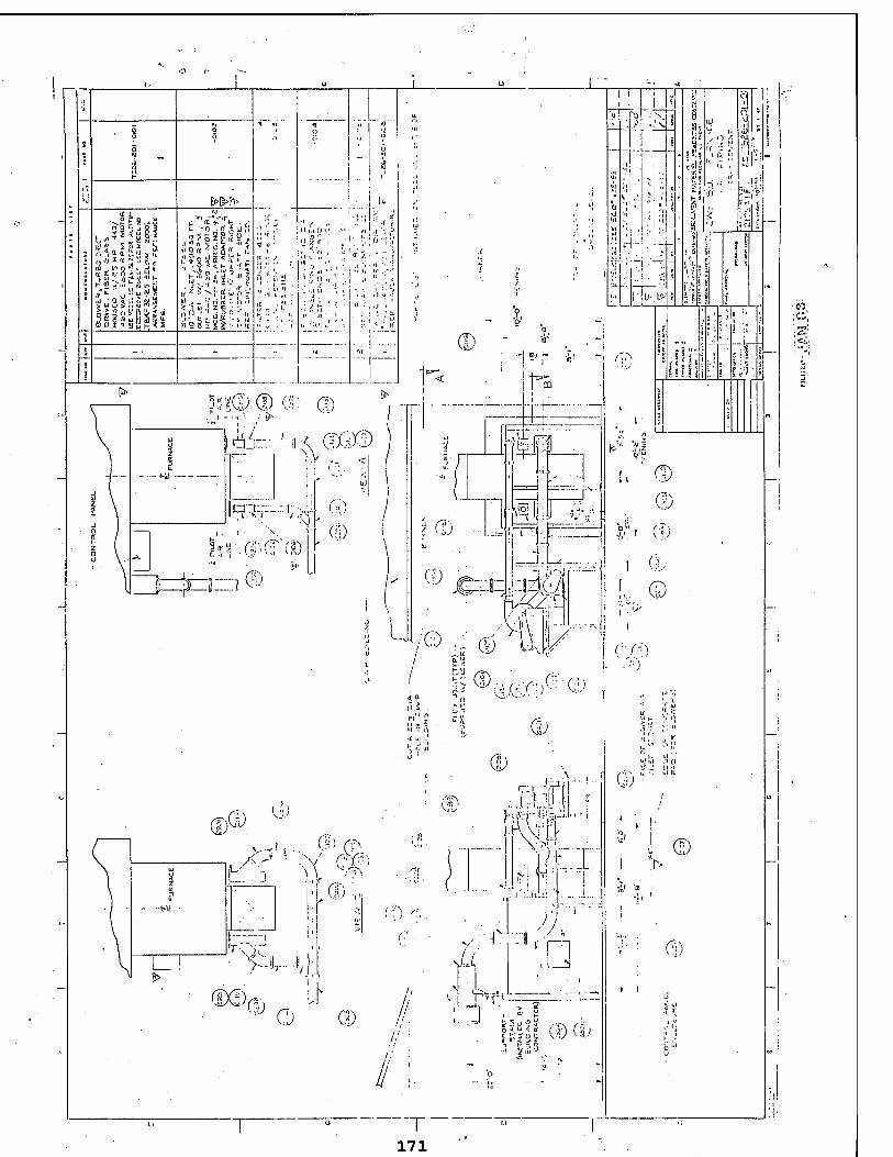
313d
,, i i a L, u n >') x « 3 -' ID „ m o '?. a: a at o * i>
> w - .o \tv \' t- a _S,, >- K
«T^o-A' S u 3 5 !'.' Si S a 3 -s üi ü m a i i B g
5"
H9
&>&*> tt 1
tO« Zoir
y •< t- " s ;i '■ » '"'
'h.ld'
^;;;.; ' ,l
;;-*K.: ' ' I) V 1.1 '
■I •'•(>• :' ', '.' ■,( ■;*; II'
|<I ftl -
t. •, 'i ' V,.: ••■ MV
lit
y z a
t-lt ■ -
j
l_! ■ V-»7
~SA^;(?,)
■<0.)

172
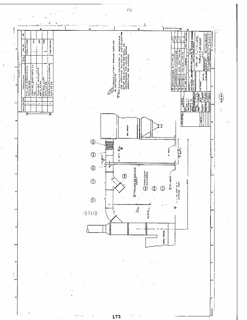
173
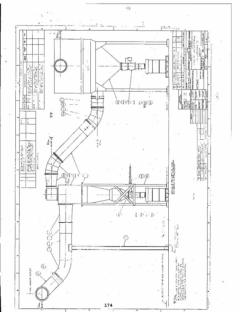
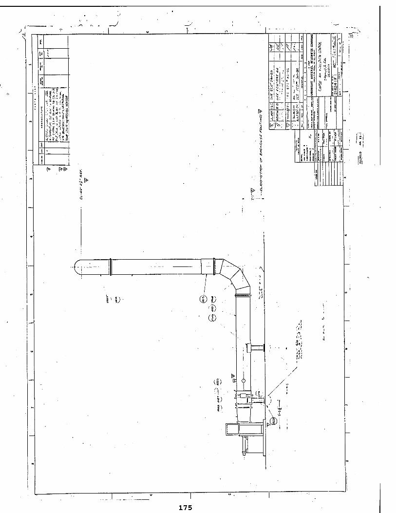
~J
':.'v,..s; > ; i 8 " n- ■»
[*• [&-&>
¥ V
■ t
c* [V;. EH
%! >5'i
; cvj 5(0
a r,| j *
Hi
!!l
>
-6 U
175
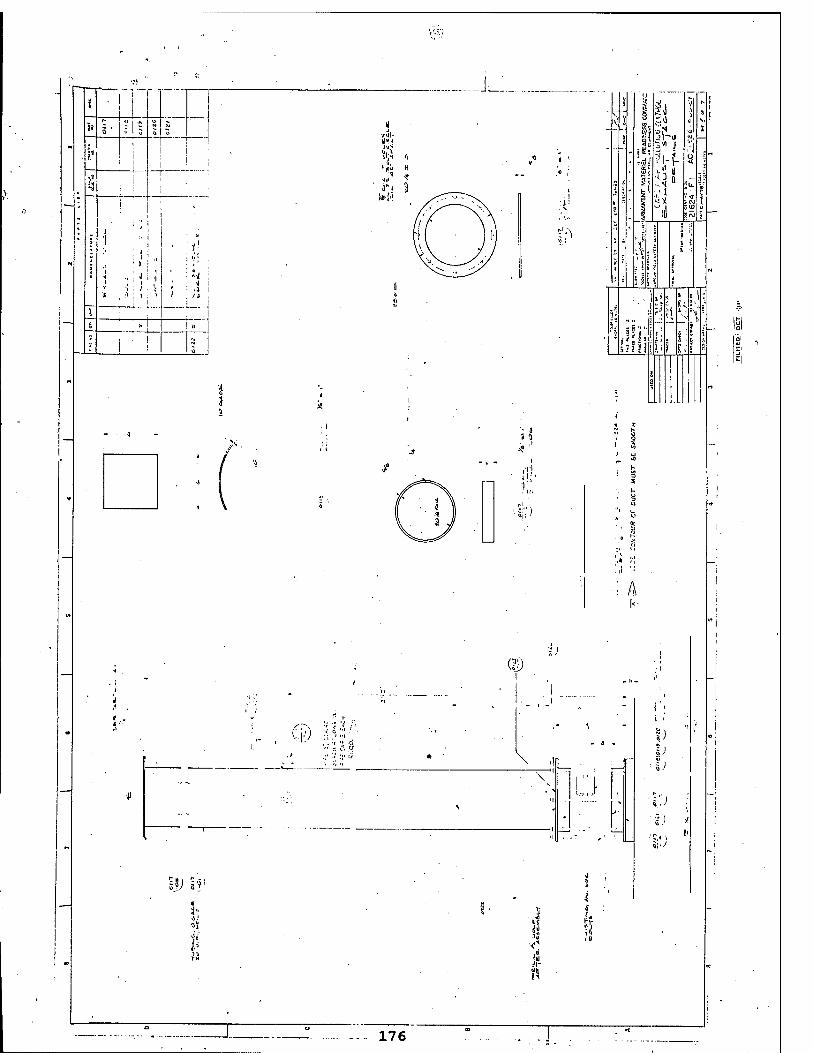
> I
t i
"J : 0 I
■a I
tfvlh Id«1*
ii;-t il
•;•. H
ON 3 »Jo
1
^
( 'S« J
-,* u
/I
a ' ; E i
3U> 5«
E.i
A i<
il:,'
■■ ;■;)
A
BW H
;.}
~) s.l
'I.'
5;./'
176
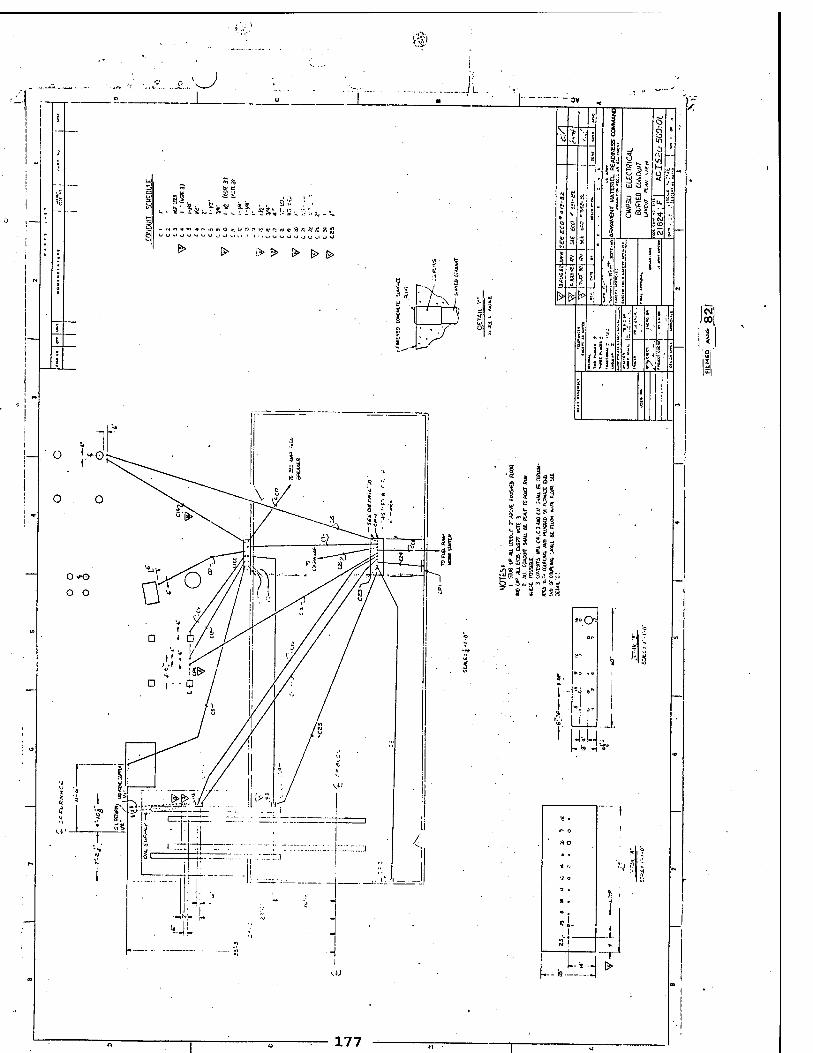
ftfl
1
> Q * b !i- a *.< a> r: w * S A N K ?, *
t> l> |> 0 o |> ? 1
£4 o r* n
a«','" *! £!« it! II
I Jga 1 «3!
•a s 8 «-a
* l 1 8s9'
»O
r: 3 * 3
1
* . i .1- o
ao
* u ?
'if O
a ■ £ i -j
• , i •J. .
i l 3 i
....*kj i
■'■{ PA
177
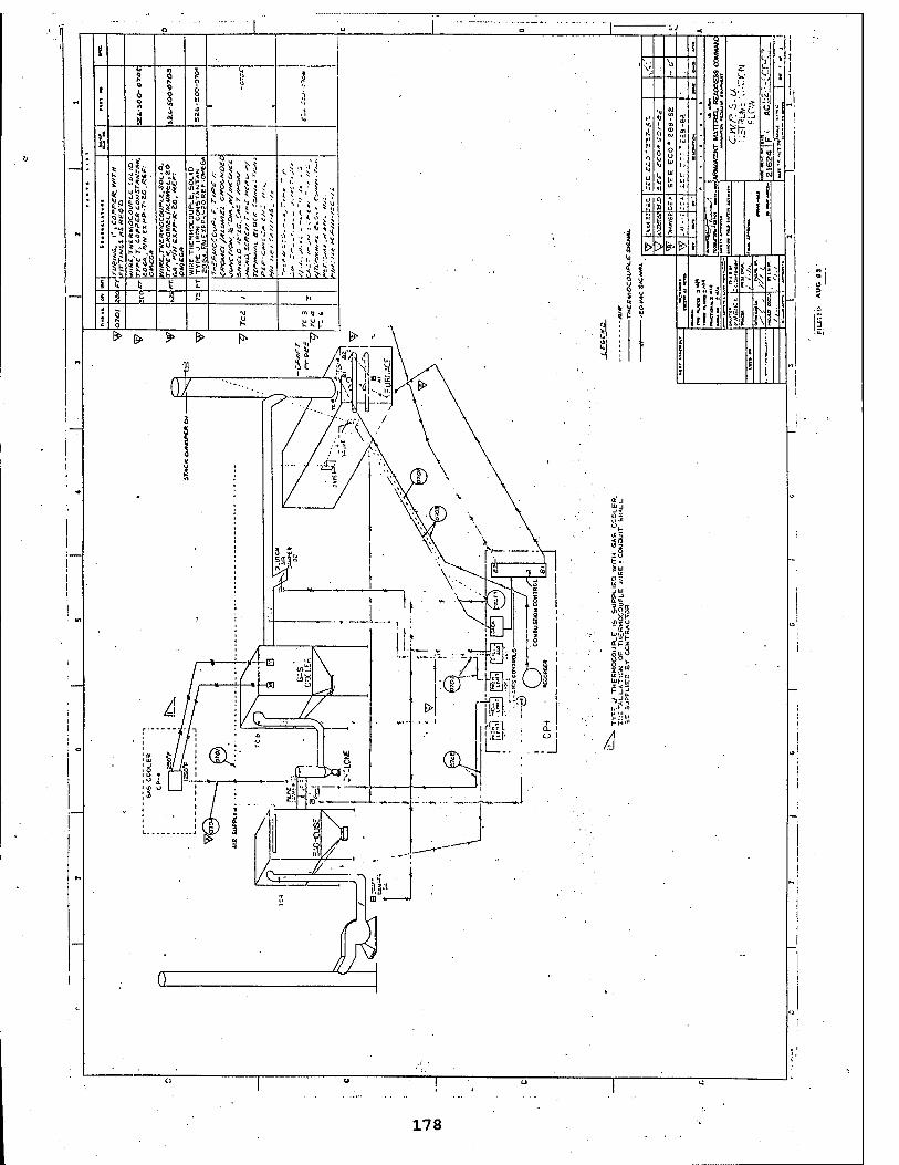
178