contactors transducers components for industry … · components for energy application components...
TRANSCRIPT

AutomaticDoorSystems
5020
709-
INB
-Sep
t200
9-BT
SAdv
.Tor
ino-
Prin
ted
byGR
AFAR
T
Official Microelettrica Scientifica dealer
E M C Tr a c t i o n S . r. l .
DC High SpeedCircuit BreakersIR2000IR6000IR6000MPIR6000MLIRAIR2000SVIR6000SV
DC SwitchgearsDIACLAD
Stationary ResistorsNeutral GroundingHarmonic FilterLoad BanksStarting/Braking/DischargeLine Test
On Board ResistorsBrakingContinuous Duty ControlImpulsive Duty Control
Res i s to r s
C o m p o n e n t s f o r R a i l o n B o a r d A p p l i c a t i o n
RelaysA lineM lineMC lineN-DIN lineUltra line
SoftwareMSCom2
TransducersMHCO lineMHIT lineEurometerIntegrameter
E lec t ron i cSwi t ches
ContactorsLTHS lineLTC lineLTHH/LTE/LTP lineLTNS lineN line
DisconnectorsLTHM/P-U/D lineLTMP line
For information on salesnetwork and products please visit
www.microelettrica.com
C o m p o n e n t s f o r E n e r g y A p p l i c a t i o n
C o m p o n e n t s f o r D C S u b s t a t i o n A p p l i c a t i o n
C o m p o n e n t s f o r I n d u s t r y A p p l i c a t i o n
ContactorsDisconnectorsDC High Speed Circuit BreakersPower ResistorsProtection Relays

2 3
Components for Industr y Appl icat ion
Industrial Evolution
Microelettrica Scientifica boasts
decades of experience in designing
and manufacturing products for
Industrial Application of high quality
and performances. Today,
Microelettrica Scientifica wide
ranges of contactors, disconnectors,
power resistors and protection
relays, together with EMC Traction
DC high speed circuit breakers, have
become the standard of reference
for a growing number of highly
qualified customers in several
industries all over the world.
Know how in continuous evolution
The frontiers of industrial and
utilities market, from crane
operation to motor control, from LV
utilities components to the
automation industry, are constantly
changing. Microelettrica Scientifica
is evolving with them through
continuous innovation of products
and technologies. All the steps of
our processes, from product
conception to product validation,
from choice of materials to final
routine tests, are accurately
controlled to guarantee total safety
of equipment, persons and plants, as
well as full customers satisfaction,
but more importantly to constantly
find innovative solutions that improve
the cost/performance/features
balance of our products.
We work together with our customers
Our industrial philosophy is to
manage the evolution of our
products in full coordination and
collaboration with our customers.
Since the first contacts, we are
pleased to foster relations with
them. In this way we can help in
selecting the product from our wide
range which better fits the
requirements. And, in case of special
requirements, we are always eager
to develop custom-designed
products: our company is well
prepared to manage the most
challenging projects and our
factories will easily realize them.
Made in Microelettrica Scientifica
To achieve the best results,
Microelettrica Scientifica develops
and produces the entire range of
products in its own facilities in
Rozzano and Lacchiarella, as well as
the EMC Traction facility in
Vimodrone, all very near to Milano.
But we also run operations in USA,
South Africa, India and China.
Wherever in the world customers
know they can always count on
quality, excellence and accuracy in
the realization of each single
product and component, but also
get supported locally.
Applications
Generator control
Crane and motor control
Heavy industry
Light industry
Products
ContactorsDisconnectors
DC High Speed Circuit Breakers
Power Resistors
Protection Relays
Components for Industr y Appl icat ion
4 5Contac to r s
Applications
Line contactor
Power or auxiliary converter input
Filter pre-charging
Traction motors on-load disconnection
Electromagnetic brakes
Heating/Air conditioning systems
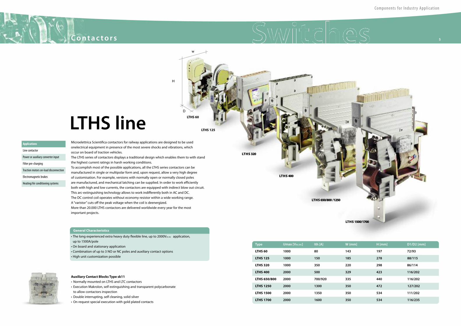
Microelettrica Scientifica contactors for railway applications are designed to be used
onelectrical equipment in presence of the most severe shocks and vibrations, which
occur on board of traction vehicles.
The LTHS series of contactors displays a traditional design which enables them to with stand
the highest current ratings in harsh working conditions.
To accomplish most of the possible applications, all the LTHS series contactors can be
manufactured in single or multipolar form and, upon request, allow a very high degree
of customisation. For example, versions with normally open or normally closed poles
are manufactured, and mechanical latching can be supplied. In order to work efficiently
both with high and low currents, the contactors are equipped with indirect blow out circuit.
This arc-extinguishing technology allows to work indifferently both in AC and DC.
The DC control coil operates without economy resistor within a wide working range.
A “varistor” cuts off the peak voltage when the coil is deenergized.
More than 20.000 LTHS contactors are delivered worldwide every year for the most
important projects.
Auxiliary Contact Blocks Type sk11
• Normally mounted on LTHS and LTC contactors
• Execution Makrolon, self extinguishing and transparent polycarbonate
to allow contactors inspection
• Double interrupting, self cleaning, solid silver
• On request special execution with gold plated contacts
• The long experienced extra heavy duty flexible line, up to 2000VDC/AC application,
up to 1500A/pole
• On board and stationary application
• Combination of up to 3 NO or NC poles and auxiliary contact options
• High unit customization possible
LTHS line
Umax [VAC/DC] Ith [A] W (mm] H [mm] D1/D2 [mm]
LTHS 60
Type
143 197 72/93
LTHS 125 1000 150 185 278 88/115
LTHS 320 1000 350 220 298 86/114
LTHS 400 2000 500 329 423 116/202
LTHS 650/800 2000 700/920 335 440 116/202
LTHS 1250 2000 1300 350 472 127/202
LTHS 1500 2000 1350 350 534 111/202
LTHS 1700 2000 1600 350 534 116/235
1000
H
D
w
LTHS 125
LTHS 320
LTHS 400
LTHS 1500/1700
LTHS 650/800 /1250
LTHS 60
80
General Characteristics

LTC 100
LTC 100 NC
LTCS 250
LTCS 250 2 poles
LTC 250 NC
LTCH 250
LTCH 60
LTCH 1000
LTCS 250 3 poles
Auxiliary Contact Blocks Type rk11
• Contacts based on Reed relay technology
• Sealed tips, not affected by harsh environmental conditions
• Shielding case from external magnetic fields
• Same mechanical interface of standard SK11auxiliary blocks
• Power rating 10 VA
Umax [VAC/DC] Ith [A] W [mm] H [mm] D [mm]
LTC 100
Type
100 106 127,5 63
LTC 100 2 poles 1000 100/200 120 127 93
LTC 100 NC 1000 100 106 155 60
LTCS 250 1000 250 140 156,5 86
LTCS 250 2 poles 2000 250/500 140 156,5 109
LTCS 250 3 poles 2000 250 140 156,5 154
LTC 250 NC 2000 250 140 196 78
LTCH 250 1000 250 154 176 86
LTCH 60 4000 60 168 220 88
LTCH 60 2 poles 4000 60/120 220 168 125
LTCH 1000 2000 1000 385 300 93
1000
LTC lineApplications
Auxiliary converter input
Filter pre-charging
Electromagnetic brakes
Heating/Air conditioning systems
Line contactor
The LTC series contactors, thanks to their excellent balance between dimensions,
performances and strength, are suitable for all those applications on board which demand
a small, smart device. Their design encourages applications where high operating frequencies
and small available spaces are important requirements.
Like all Microelettrica Scientifica contactors, the LTC series are based on a standard concept,
but a very high level of customisation can be achieved by replacing few key components.
Normally open and normally closed poles can be fitted, as well as mechanical latching.
The breaking circuit is equipped with permanent magnets to work efficiently both with
high and low currents.
The DC control coil operates without economy resistor within a wide working range.
A “varistor” cuts off the peak voltage when the coil is deenergized.
More than 20.000 LTC contactors are delivered worldwide for every year the most
important projects.
H
D
w
• The modern and compact heavy duty line, up to 4000VDC/AC application, up to 1000A/pole
• On board and stationary application
• 1-2-3 pole configuration mostly available, NO and NC poles, permanent magnets or indirect
arc blowouts
• Flexible control and auxiliary contacts options, customization possible
General Characteristics
Components for Industr y Appl icat ion
6 7Contac to r s
Components for Industr y Appl icat ion
8 9Contac to r s
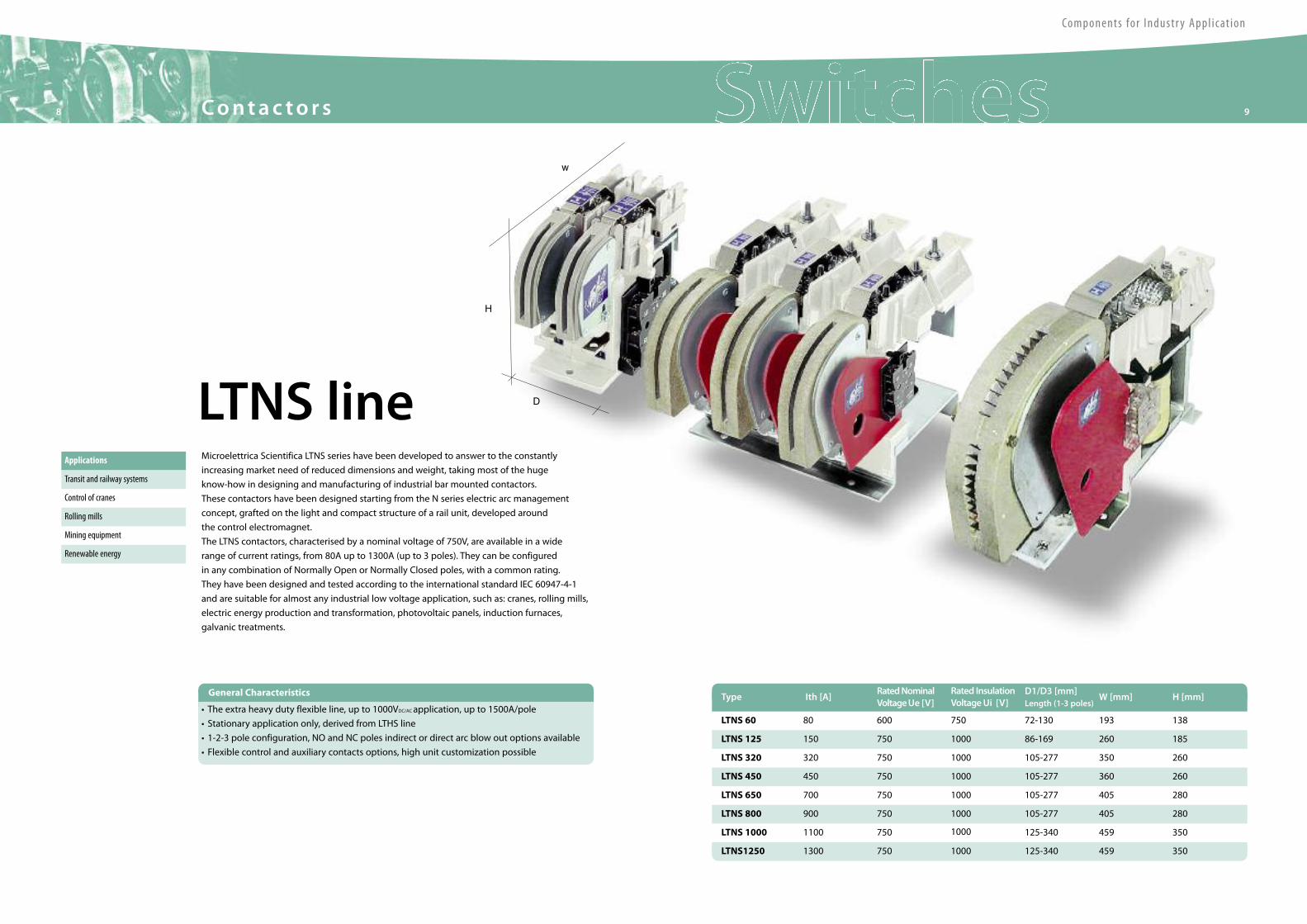
LTNS lineApplications
Transit and railway systems
Control of cranes
Mining equipment
Renewable energy
Rolling mills
Microelettrica Scientifica LTNS series have been developed to answer to the constantly
increasing market need of reduced dimensions and weight, taking most of the huge
know-how in designing and manufacturing of industrial bar mounted contactors.
These contactors have been designed starting from the N series electric arc management
concept, grafted on the light and compact structure of a rail unit, developed around
the control electromagnet.
The LTNS contactors, characterised by a nominal voltage of 750V, are available in a wide
range of current ratings, from 80A up to 1300A (up to 3 poles). They can be configured
in any combination of Normally Open or Normally Closed poles, with a common rating.
They have been designed and tested according to the international standard IEC 60947-4-1
and are suitable for almost any industrial low voltage application, such as: cranes, rolling mills,
electric energy production and transformation, photovoltaic panels, induction furnaces,
galvanic treatments.
Type Ith [A]RatedNominalVoltageUe [V]
Rated InsulationVoltageUi [V]
D1/D3 [mm]Length (1-3 poles)
W [mm]
LTNS 60 80 600 750 72-130 193
LTNS 125 150 750 1000 86-169 260
LTNS 320 320 750 1000 105-277 350
LTNS 450 450 750 1000 105-277 360
LTNS 650 700 750 1000 105-277 405
LTNS 800 900 750 1000
1000
105-277 405
LTNS1250 1300 750 1000 125-340 459
LTNS 1000 1100 750 125-340 459
H [mm]
138
185
260
260
280
280
350
350
H
D
w
• The extra heavy duty flexible line, up to 1000VDC/AC application, up to 1500A/pole
• Stationary application only, derived from LTHS line
• 1-2-3 pole configuration, NO and NC poles indirect or direct arc blow out options available
• Flexible control and auxiliary contacts options, high unit customization possible
General Characteristics
10 11Contac to r s
Components for Industr y Appl icat ion
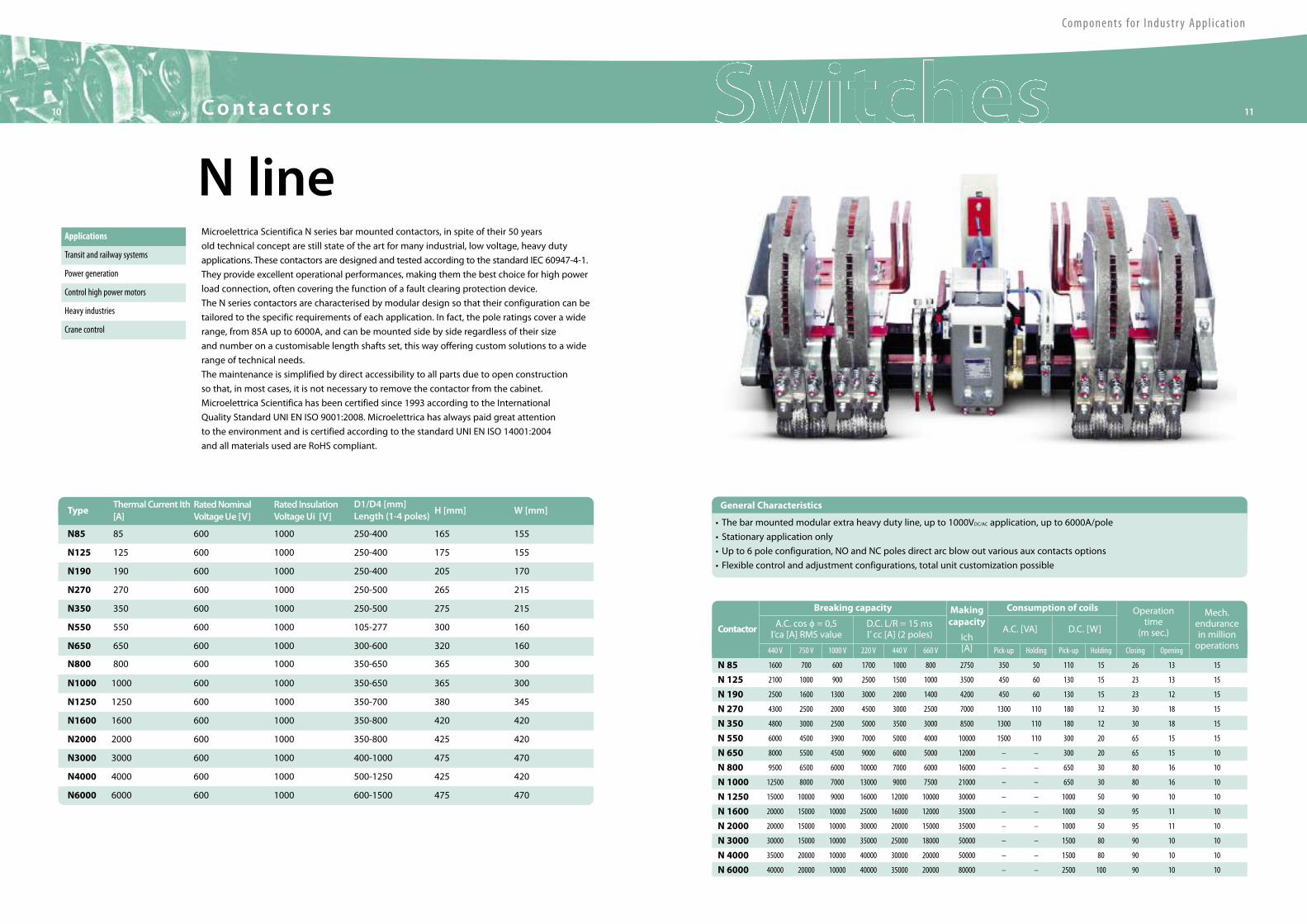
N lineMicroelettrica Scientifica N series bar mounted contactors, in spite of their 50 years
old technical concept are still state of the art for many industrial, low voltage, heavy duty
applications. These contactors are designed and tested according to the standard IEC 60947-4-1.
They provide excellent operational performances, making them the best choice for high power
load connection, often covering the function of a fault clearing protection device.
The N series contactors are characterised by modular design so that their configuration can be
tailored to the specific requirements of each application. In fact, the pole ratings cover a wide
range, from 85A up to 6000A, and can be mounted side by side regardless of their size
and number on a customisable length shafts set, this way offering custom solutions to a wide
range of technical needs.
The maintenance is simplified by direct accessibility to all parts due to open construction
so that, in most cases, it is not necessary to remove the contactor from the cabinet.
Microelettrica Scientifica has been certified since 1993 according to the International
Quality Standard UNI EN ISO 9001:2008. Microelettrica has always paid great attention
to the environment and is certified according to the standard UNI EN ISO 14001:2004
and all materials used are RoHS compliant.
Applications
Transit and railway systems
Power generation
Control high power motors
Crane control
Heavy industries
TypeThermal Current Ith[A]
RatedNominalVoltageUe [V]
Rated InsulationVoltageUi [V]
D1/D4 [mm]Length (1-4 poles)
H [mm]
N85 85 600 1000 250-400 165
N125 125 600 1000 250-400 175
N190 190 600 1000 250-400 205
N270 270 600 1000 250-500 265
N350 350 600 1000 250-500 275
N550 550 600 1000
1000
105-277 300
N800 800 600 1000 350-650 365
N650 650 600 300-600 320
W [mm]
155
155
170
215
215
160
300
160
N1000 1000 600 1000 350-650 365
N1250 1250 600 1000 350-700 380
N1600 1600 600 1000 350-800 420
N2000 2000 600 1000 350-800 425
N3000 3000 600 1000 400-1000 475
N4000 4000 600 1000
1000
500-1250 425
N6000 6000 600 600-1500 475
300
345
420
420
470
420
470
Contactor
Breaking capacity Makingcapacity
Ich[A]
Consumption of coils Operationtime
(m sec.)
Mech.endurancein millionoperations
A.C. cos o = 0,5I’ca [A] RMS value
D.C. L/R = 15 msI’ cc [A] (2 poles) A.C. [VA] D.C. [W]
440 V 750 V 1000 V 220 V 440 V 660 V Pick-up Holding Pick-up Holding Closing Opening
N 85 1600 700 600 1700 1000 800 2750 350 50 110 15 26 13 15
N 125 2100 1000 900 2500 1500 1000 3500 450 60 130 15 23 13 15
N 190 2500 1600 1300 3000 2000 1400 4200 450 60 130 15 23 12 15
N 270 4300 2500 2000 4500 3000 2500 7000 1300 110 180 12 30 18 15
N 350 4800 3000 2500 5000 3500 3000 8500 1300 110 180 12 30 18 15
N 550 6000 4500 3900 7000 5000 4000 10000 1500 110 300 20 65 15 15
N 650 8000 5500 4500 9000 6000 5000 12000 – – 300 20 65 15 10
N 800 9500 6500 6000 10000 7000 6000 16000 – – 650 30 80 16 10
N 1000 12500 8000 7000 13000 9000 7500 21000 – – 650 30 80 16 10
N 1250 15000 10000 9000 16000 12000 10000 30000 – – 1000 50 90 10 10
N 1600 20000 15000 10000 25000 16000 12000 35000 – – 1000 50 95 11 10
N 2000 20000 15000 10000 30000 20000 15000 35000 – – 1000 50 95 11 10
N 3000 30000 15000 10000 35000 25000 18000 50000 – – 1500 80 90 10 10
N 4000 35000 20000 10000 40000 30000 20000 50000 – – 1500 80 90 10 10
N 6000 40000 20000 10000 40000 35000 20000 80000 – – 2500 100 90 10 10
• The bar mounted modular extra heavy duty line, up to 1000VDC/AC application, up to 6000A/pole
• Stationary application only
• Up to 6 pole configuration, NO and NC poles direct arc blow out various aux contacts options
• Flexible control and adjustment configurations, total unit customization possible
General Characteristics
12 13D i s connec to r s
Components for Industr y Appl icat ion
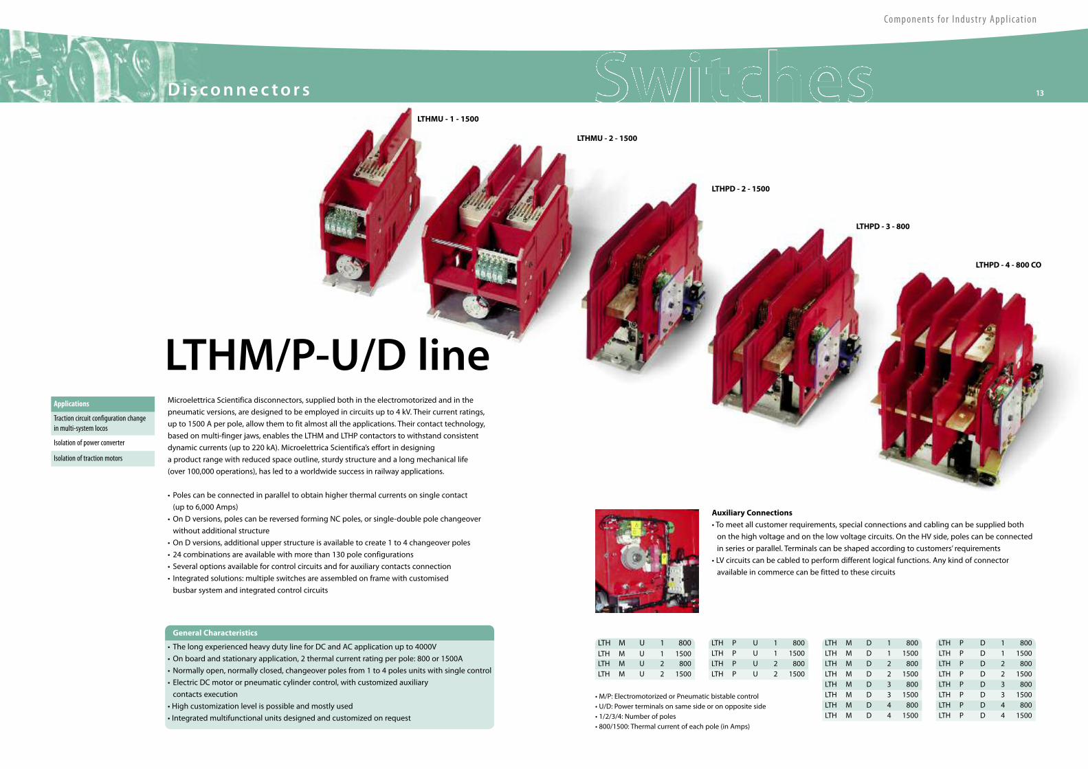
Microelettrica Scientifica disconnectors, supplied both in the electromotorized and in the
pneumatic versions, are designed to be employed in circuits up to 4 kV. Their current ratings,
up to 1500 A per pole, allow them to fit almost all the applications. Their contact technology,
based on multi-finger jaws, enables the LTHM and LTHP contactors to withstand consistent
dynamic currents (up to 220 kA). Microelettrica Scientifica’s effort in designing
a product range with reduced space outline, sturdy structure and a long mechanical life
(over 100,000 operations), has led to a worldwide success in railway applications.
• Poles can be connected in parallel to obtain higher thermal currents on single contact
(up to 6,000 Amps)
• On D versions, poles can be reversed forming NC poles, or single-double pole changeover
without additional structure
• On D versions, additional upper structure is available to create 1 to 4 changeover poles
• 24 combinations are available with more than 130 pole configurations
• Several options available for control circuits and for auxiliary contacts connection
• Integrated solutions: multiple switches are assembled on frame with customised
busbar system and integrated control circuits
LTHM/P-U/D lineApplications
Isolation of traction motors
Traction circuit configuration changein multi-system locos
Isolation of power converter
Auxiliary Connections
• To meet all customer requirements, special connections and cabling can be supplied both
on the high voltage and on the low voltage circuits. On the HV side, poles can be connected
in series or parallel. Terminals can be shaped according to customers’ requirements
• LV circuits can be cabled to perform different logical functions. Any kind of connector
available in commerce can be fitted to these circuits
• M/P: Electromotorized or Pneumatic bistable control• U/D: Power terminals on same side or on opposite side• 1/2/3/4: Number of poles• 800/1500: Thermal current of each pole (in Amps)
LTH P D 1 800LTH M U 1 1500 LTH P D 1 1500LTH M U 2 800 LTH P D 2 800LTH M U 2 1500 LTH P D 2 1500
LTH P D 3 800LTH P D 3 1500LTH P D 4 800LTH P D 4 1500
LTHMU - 1 - 1500
LTHMU - 2 - 1500
LTHPD - 2 - 1500
LTHPD - 3 - 800
LTHPD - 4 - 800 CO
LTH M U 1 800 LTH P U 1 800LTH P U 1 1500LTH P U 2 800LTH P U 2 1500
LTH M D 1 800LTH M D 1 1500LTH M D 2 800LTH M D 2 1500LTH M D 3 800LTH M D 3 1500LTH M D 4 800LTH M D 4 1500
• The long experienced heavy duty line for DC and AC application up to 4000V
• On board and stationary application, 2 thermal current rating per pole: 800 or 1500A
• Normally open, normally closed, changeover poles from 1 to 4 poles units with single control
• Electric DC motor or pneumatic cylinder control, with customized auxiliary
contacts execution
• High customization level is possible and mostly used
• Integrated multifunctional units designed and customized on request
General Characteristics
14 15D i s connec to r s
Components for Industr y Appl icat ion
Modular Multipole-Multiposition Off-Load Disconnector with Binary Control Option
Main Features of each Pole:
• 2 versions: 1000 or 2000 A thermal current
• 3 configurations: NO or NO+NC or CO
• Integrated control device for command logic
• Fully modular construction, up to 12 poles
• Visual indication of pole status
• Maintenance-free
Main Features Control:
• Electric motor actuated
• Electronic control of poles positions
• Virtually infinite combinations of poles positions
• Predetermined positions accessed sequentially or by dedicated control signal
Options:
• Binary control code module (No. of digits = No. of poles)
LTMP line
RatedVoltage (Un) 3000 V
Rated MaxVoltage (Umax) 4000 V
Insulation Reference Voltage (Ui) 4000 V
Rated Operational Current (Ie) 1000 A 2000 A
Rated Short CircuitWithstand for 15ms (Icc) 160 kA 220 kA
Rated Breaking Current at 4000VDC 400mA
Position Change Time at Uc Max 5 sec
Mechanical Endurance > 500’000 operations
Contact Opening Distance > 40mm
Dielectric Test Voltage HV to ground 12000V Aux to ground 2000V Bwn open contacts 9500V
Auxiliary Contacts (type SJ 11) 1NO+1NC per pole
Control ModuleWeight 5 kg
NO PoleWeight (per pole) 6.2 kg 7 kg
CO PoleWeight 7.5 kg 8.5 kg
NO-NC PoleWeight 8.2 kg 9 kg
Operating Temperature Range -50°C ÷ +85°C
Control Voltage (Uc) 24 / 72 / 110 VDC
Control VoltageWorking Range at +85°c ± 30%
Absorbed Power at 20°c and Uc Max 150W
Technical Data
Dimensions
Applications
Isolation of traction motors
Traction circuit configuration changein multi-system locos
Isolation of power converter
Version1000 A2000 A
Pole Width90 mm110 mm
400
325
X
Pole Configuration
NO Pole NO-NCPole
CO Pole
Components for Industr y Appl icat ion
16 17DC H igh Speed C i rcu i t B reake r s
The IRA series are single pole, magnetic blow out, trip free, air circuit breakers.
The breaker closing device is electromagnetic (for Substation and Industry applications)
or electropneumatic (for Locomotives) type.
The breaker is held closed by an holding coil and is equipped with a direct acting
unidirectional over-current trip device.
Type IRAMagnetic IRA Magnetic/Pneumatic
RatedVoltage [V] Un 1500 3000
Rated Current [A] In Up to 3000 Up to 3000
Short Circuit Breaking Capacity Ue 1800 [V] 3600 [V](EN 50123) (IEC77)
Icc 100 [kA]-Peak 60 [kA]-Peak
Icc 60 [kA]-Steady State 40 [kA]-Steady State
RatedVoltage Auxiliary Circuit [VDC] Un 24 ÷250 24 ÷250
Technical Data
Applications
DC Substation
Industry
EMU
Locomotives
IRA seriesHigh Speed Circuit Breaker Type IRA With Holding Coil for Substations and Industrial
Applications or Closing Pneumatic Mechanism for Locomotives
Components for Industr y Appl icat ion
18 19DC H igh Speed C i rcu i t B reake r s
The IR2000 series are single pole, magnetic blow out, trip free, air circuit breakers.
The breakers closing mechanism is the indipendent type motor operated.
The IR2000 Circuit Breaker is held closed by holding coil or by permanent magnet device and
is equipped with a direct acting over-current trip device which may be either unidirectional
and bidirectional.
The breaker conforms to ANSI C 37-14, ANSI C 37-16 and EN 50123 Standard.
Applications
DC Substation
Industry
93940 38 10
1A
68 7 5
Kx Kch
IDENTIFICAZIONE
InUe
BOB. RITENUTABOB. APERTURA
MOT. CHIUSURAAVcc
NUMEROTIPO
VccAccVcc
9B
3B
6B
4B5B
7B8B
1B2B
3B
10B
11B
12B
9B
EMC Traction s.r.l.INTERRUTTOREEXTRARAPIDO
RatedVoltage [V] Un 750 1500
Rated Current [A] In Up to 3000 Up to 3000
Short Circuit Breaking Capacity Ue 800 [V](ANSI C 37-14)
Icc 89 [kA]-Peak
Icc 82 [kA]-Steady State
Short Circuit Breaking Capacity Ue 900 [V] 1800 [V](EN 50123)
Icc 50 [kA]-Peak 45 [kA]-Peak
Icc 30 [kA]-Steady State 25 [kA]-Steady State
RatedVoltage Auxiliary Circuit [VDC] Un 24 ÷220 24 ÷220
Technical Data
IR2000 seriesHigh Speed Circuit Breaker Type IR2000 for Substation
and Industry Applications

Components for Industr y Appl icat ion
20 21DC H igh Speed C i rcu i t B reake r s
The IR6000 Permanent magnet latch series are fixed or withdrawable, single pole, magnetic
blow out, trip free, air circuit breakers.
The closing mechamism is an independent motor operated type.
The breaker is held closed by a permanent magnet device and is equipped with a direct
acting over-current trip device which may be either unidirectional or bidirectional.
The breaker conforms to ANSI C 37-14, ANSI C 37-16 and EN50123 Standard.
RatedVoltage [V] Un 750 1200 1500
Rated Current [A] In Up to 8000 Up to 8000 Up to 8000
Short Circuit Breaking Capacity Ue 800 [V] 1200 [V](ANSI C 37-14) (IR6000 4kA)
Icc 200 [kA]-Peak 135 [kA]-Peak
Icc 120 [kA]-Steady State 80 [kA]-Steady State
Short Circuit Breaking Capacity Ue 800 [V] 1800[V](EN 50123)
Icc 120 [kA] - Peak 100 [kA] - Peak
Icc 90 [kA]-Steady State 70 [kA] - Steady State
RatedVoltage Auxiliary Circuit [VDC] Un 24 ÷220 24 ÷220 24 ÷220
Technical Data
Applications
DC Substation
Industry
IR6000 MP seriesHigh Speed Circuit Breaker Type IR6000 with Permanent MagnetLatch for DC Substation and Industry Applications
Components for Industr y Appl icat ion
22 23DC H igh Speed C i rcu i t B reake r s
IR6000 seriesHigh Speed Circuit Breaker Type IR6000 with Electromagnetic Latch
for Substations and Industry Applications
The IR6000 Electromagnetic latch series are fixed or withdrawable, single pole magnetic
blow out, trip free, air circuit breakers.
The closing mechanism is an independent motor operated type.
The breaker is held closed by holding coil and is equipped with a direct acting over-current
trip device which may be either unidirectional or bidirectional.
The breaker conforms to ANSI C 37-14, ANSI C 37-16 and EN 50123 Standard.
Technical Data
Applications
DC Substation
Industry
RatedVoltage [V] Un 750 1200 1500 3000
Rated Current [A] In Up to 8000 Up to 8000 Up to 8000 Up to 4000
Short Circuit Breaking Capacity Ue 800 [V] 1200 [V](ANSI C 37-14) (IR6000 4kA)
Icc 200 [kA]-Peak 132 [kA]-Peak
Icc 120 [kA]-Steady State 80 [kA]-Steady State
Short Circuit Breaking Capacity Ue 800 [V] 1800[V] 3600[V](EN 50123)
Icc 120 [kA] - Peak 100 [kA] - Peak 61<[kA] - Peak
Icc 90 [kA]-Steady State 70 [kA] - Steady State 40 [kA] - Steady State
100 [kA] - SteadyState
70 [kA] - Steady State
RatedVoltage Auxiliary Circuit [VDC] Un 24 ÷220 24 ÷220 24 ÷220 24 ÷220
Components for Industr y Appl icat ion
24 25DC H igh Speed C i rcu i t B reake r s
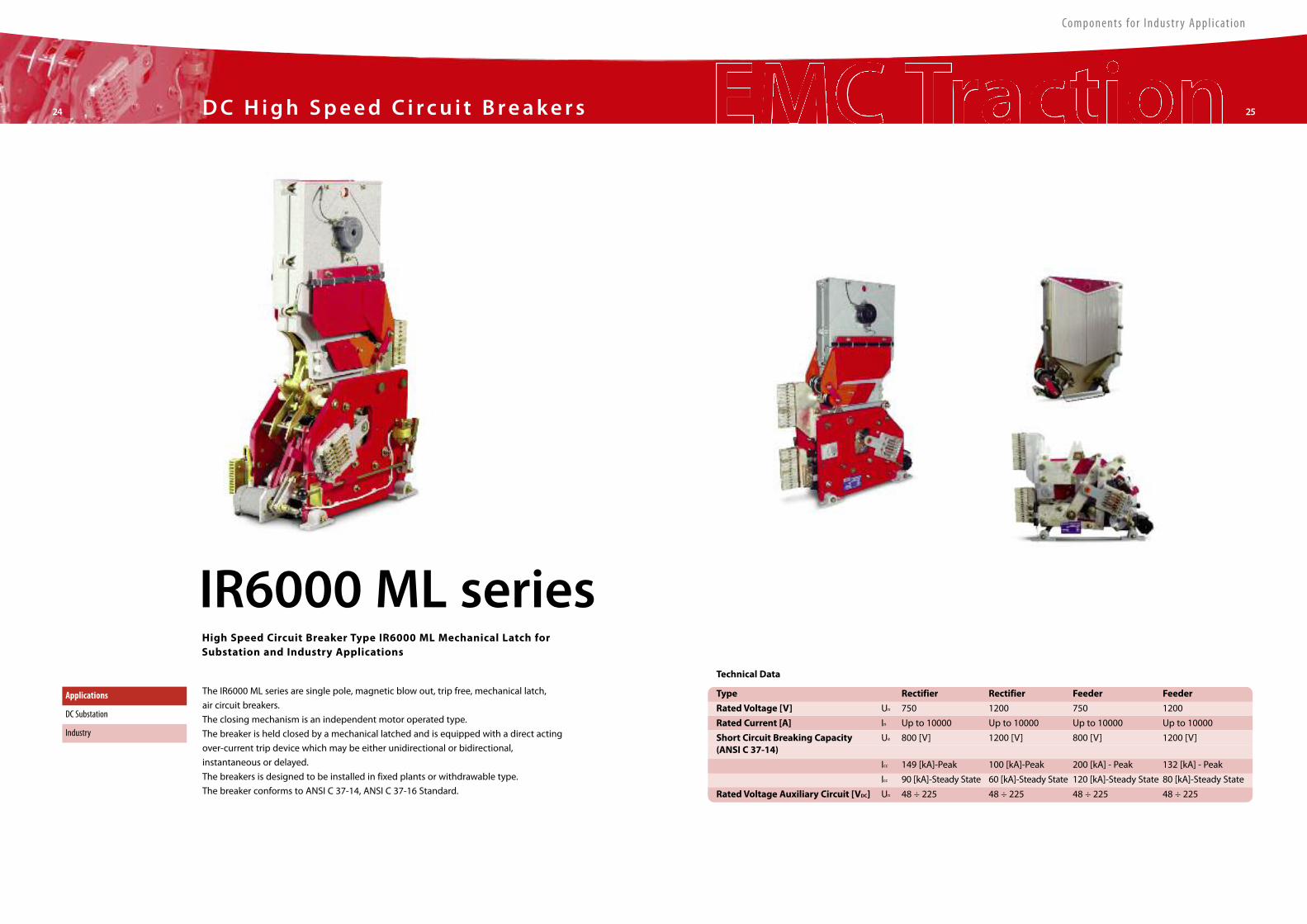
The IR6000 ML series are single pole, magnetic blow out, trip free, mechanical latch,
air circuit breakers.
The closing mechanism is an independent motor operated type.
The breaker is held closed by a mechanical latched and is equipped with a direct acting
over-current trip device which may be either unidirectional or bidirectional,
instantaneous or delayed.
The breakers is designed to be installed in fixed plants or withdrawable type.
The breaker conforms to ANSI C 37-14, ANSI C 37-16 Standard.
Type Rectifier Rectifier Feeder Feeder
RatedVoltage [V] Un 750 1200 750 1200
Rated Current [A] In Up to 10000 Up to 10000 Up to 10000 Up to 10000
Short Circuit Breaking Capacity Ue 800 [V] 1200 [V] 800 [V] 1200 [V](ANSI C 37-14)
Icc 149 [kA]-Peak 100 [kA]-Peak 200 [kA] - Peak 132 [kA] - Peak
Icc 90 [kA]-Steady State 60 [kA]-Steady State 120 [kA]-Steady State 80 [kA]-Steady State
RatedVoltage Auxiliary Circuit [VDC] Un 48 ÷ 225 48 ÷ 225 48 ÷ 225 48 ÷ 225
Technical Data
Applications
DC Substation
Industry
IR6000 ML seriesHigh Speed Circuit Breaker Type IR6000 ML Mechanical Latch forSubstation and Industry Applications
Components for Industr y Appl icat ion
Sta t iona r y26 27
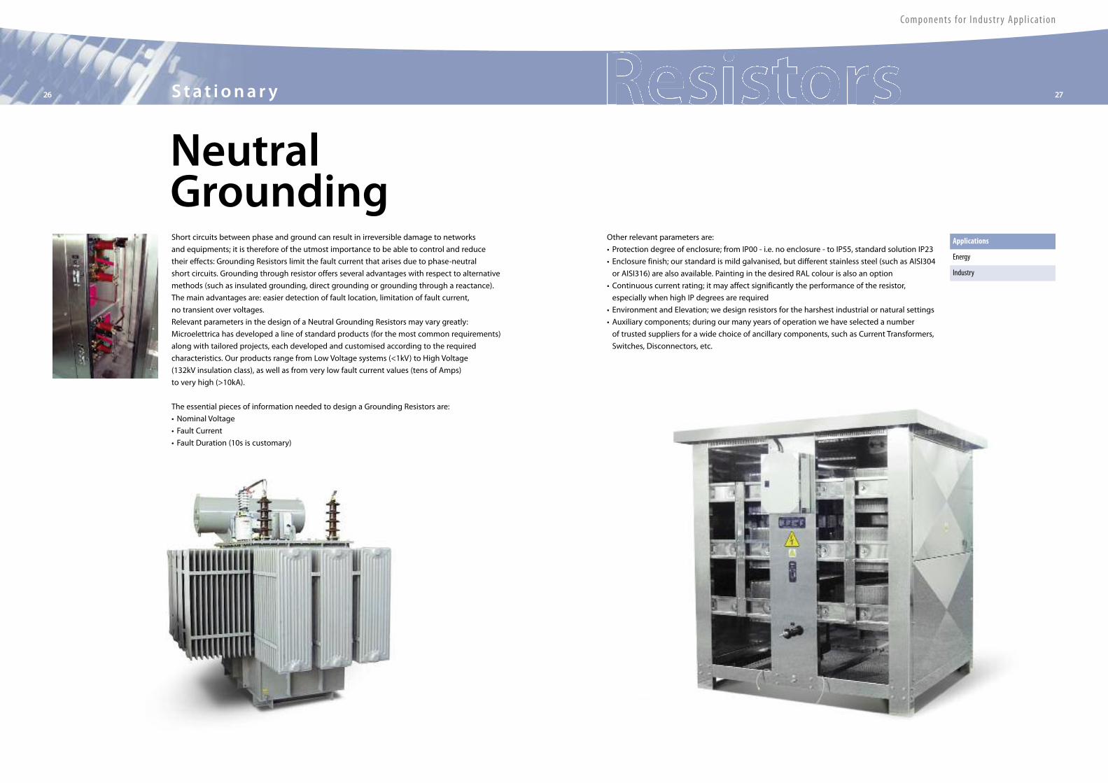
NeutralGroundingShort circuits between phase and ground can result in irreversible damage to networks
and equipments; it is therefore of the utmost importance to be able to control and reduce
their effects: Grounding Resistors limit the fault current that arises due to phase-neutral
short circuits. Grounding through resistor offers several advantages with respect to alternative
methods (such as insulated grounding, direct grounding or grounding through a reactance).
The main advantages are: easier detection of fault location, limitation of fault current,
no transient over voltages.
Relevant parameters in the design of a Neutral Grounding Resistors may vary greatly:
Microelettrica has developed a line of standard products (for the most common requirements)
along with tailored projects, each developed and customised according to the required
characteristics. Our products range from Low Voltage systems (<1kV) to High Voltage
(132kV insulation class), as well as from very low fault current values (tens of Amps)
to very high (>10kA).
The essential pieces of information needed to design a Grounding Resistors are:
• Nominal Voltage
• Fault Current
• Fault Duration (10s is customary)
Other relevant parameters are:
• Protection degree of enclosure; from IP00 - i.e. no enclosure - to IP55, standard solution IP23
• Enclosure finish; our standard is mild galvanised, but different stainless steel (such as AISI304
or AISI316) are also available. Painting in the desired RAL colour is also an option
• Continuous current rating; it may affect significantly the performance of the resistor,
especially when high IP degrees are required
• Environment and Elevation; we design resistors for the harshest industrial or natural settings
• Auxiliary components; during our many years of operation we have selected a number
of trusted suppliers for a wide choice of ancillary components, such as Current Transformers,
Switches, Disconnectors, etc.
Applications
Energy
Industry
Sta t iona r y28 29
Components for Industr y Appl icat ion
The essential pieces of information needed to design an Harmonic Filters Resistors are:
• Nominal Voltage
• Current or Power
• Ohmic Value (with tolerance in %)
Other relevant parameters are:
• B.I.L.
• Required Insulation Level; HV terminal to hearth, LV terminal to earth, between terminals
• Clearance and Creepage
• Enclosure finish; our standard is mild galvanised, but different stainless steel (such as AISI304
or AISI316) are also available. Painting in the desired RAL colour is also an option
• Environment; we design resistors for the harshest industrial or natural settings
• Maximum Inductance
• Bushing Layout; top or side mounted
• Mounting; three-phase stacked, side by side, others
Harmonic FilterFundamental frequency f First harmonic 2f Second harmonic 3f
Applications
Energy
Industry
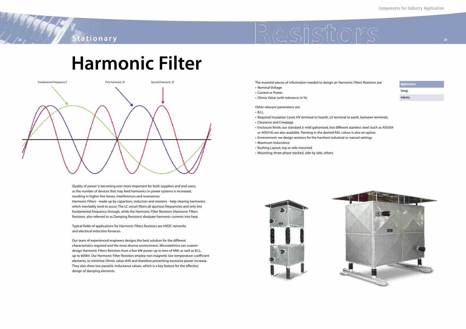
Quality of power is becoming ever more important for both suppliers and end users,
as the number of devices that may feed harmonics in power systems is increased,
resulting in higher line losses, interferences and resonances.
Harmonic Filters - made up by capacitors, inductors and resistors - help clearing harmonics
which inevitably tend to occur. The LC circuit filters all spurious frequencies and only lets
fundamental frequency through, while the Harmonic Filter Resistors (Harmonic Filters
Resistors, also referred to as Damping Resistors) dissipate harmonic currents into heat.
Typical fields of applications for Harmonic Filters Resistors are HVDC networks
and electrical induction furnaces.
Our team of experienced engineers designs the best solution for the different
characteristics required and the most diverse environment. Microelettrica can custom
design Harmonic Filters Resistors from a few kW power up to tens of MW, as well as B.I.L.
up to 600kV. Our Harmonic Filter Resistors employ non-magnetic low temperature-coefficient
elements, to minimise Ohmic value drift and therefore preventing excessive power increase.
They also show low parasitic inductance values, which is a key feature for the effective
design of damping elements.
Sta t iona r y30 31
Components for Industr y Appl icat ion
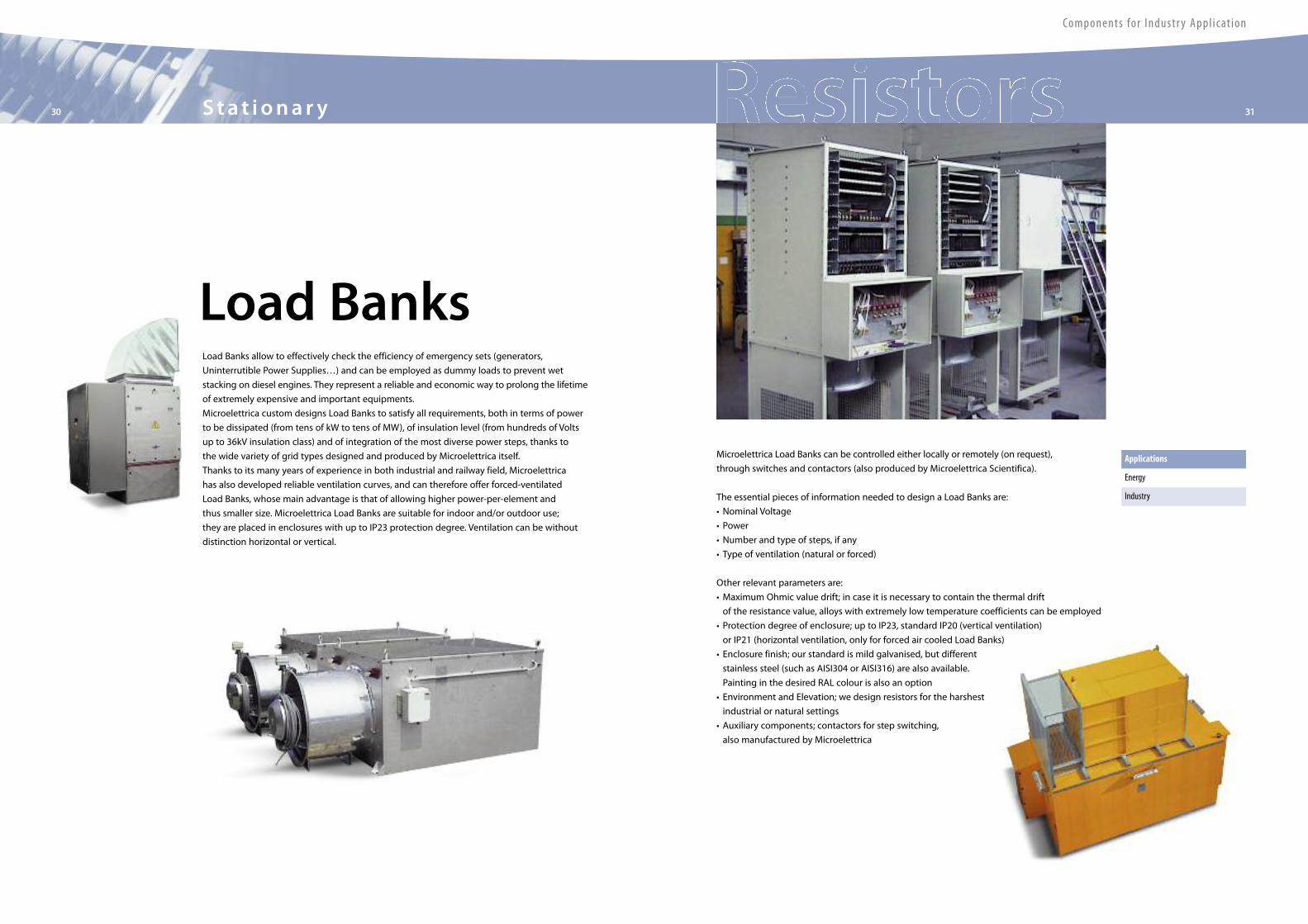
Load BanksLoad Banks allow to effectively check the efficiency of emergency sets (generators,
Uninterrutible Power Supplies…) and can be employed as dummy loads to prevent wet
stacking on diesel engines. They represent a reliable and economic way to prolong the lifetime
of extremely expensive and important equipments.
Microelettrica custom designs Load Banks to satisfy all requirements, both in terms of power
to be dissipated (from tens of kW to tens of MW), of insulation level (from hundreds of Volts
up to 36kV insulation class) and of integration of the most diverse power steps, thanks to
the wide variety of grid types designed and produced by Microelettrica itself.
Thanks to its many years of experience in both industrial and railway field, Microelettrica
has also developed reliable ventilation curves, and can therefore offer forced-ventilated
Load Banks, whose main advantage is that of allowing higher power-per-element and
thus smaller size. Microelettrica Load Banks are suitable for indoor and/or outdoor use;
they are placed in enclosures with up to IP23 protection degree. Ventilation can be without
distinction horizontal or vertical.
Microelettrica Load Banks can be controlled either locally or remotely (on request),
through switches and contactors (also produced by Microelettrica Scientifica).
The essential pieces of information needed to design a Load Banks are:
• Nominal Voltage
• Power
• Number and type of steps, if any
• Type of ventilation (natural or forced)
Other relevant parameters are:
• Maximum Ohmic value drift; in case it is necessary to contain the thermal drift
of the resistance value, alloys with extremely low temperature coefficients can be employed
• Protection degree of enclosure; up to IP23, standard IP20 (vertical ventilation)
or IP21 (horizontal ventilation, only for forced air cooled Load Banks)
• Enclosure finish; our standard is mild galvanised, but different
stainless steel (such as AISI304 or AISI316) are also available.
Painting in the desired RAL colour is also an option
• Environment and Elevation; we design resistors for the harshest
industrial or natural settings
• Auxiliary components; contactors for step switching,
also manufactured by Microelettrica
Applications
Energy
Industry
Components for Industr y Appl icat ion
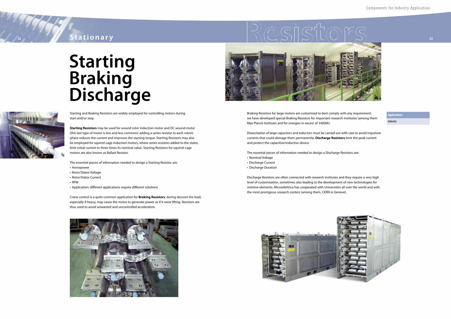
StartingBrakingDischargeStarting and Braking Resistors are widely employed for controlling motors during
start and/or stop.
Starting Resistorsmay be used for wound rotor induction motor and DC wound motor
(this last type of motor is less and less common): adding a series resistor to each rotoric
phase reduces the current and improves the starting torque. Starting Resistors may also
be employed for squirrel cage induction motors, where series resistors added to the stator,
limit initial current to three times its nominal value. Starting Resistors for squirrel cage
motors are also known as Ballast Resistor.
The essential pieces of information needed to design a Starting Resistor are:
• Horsepower
• Rotor/Stator Voltage
• Rotor/Stator Current
• RPM
• Application; different applications require different solutions
Crane control is a quite common application for Braking Resistors: during descent the load,
especially if heavy, may cause the motor to generate power as if it were lifting. Resistors are
thus used to avoid unwanted and uncontrolled acceleration.
Applications
Industry
Braking Resistors for large motors are customised to best comply with any requirement:
we have developed special Braking Resistors for important research institutes (among them
Max Planck Institute) and for energies in excess of 3400MJ.
Disexcitation of large capacitors and inductors must be carried out with care to avoid impulsive
currents that could damage them permanently. Discharge Resistors limit the peak current
and protect the capacitive/inductive device.
The essential pieces of information needed to design a Discharge Resistors are:
• Nominal Voltage
• Discharge Current
• Discharge Duration
Discharge Resistors are often connected with research institutes and they require a very high
level of customisation, sometimes also leading to the development of new technologies for
resistive elements. Microelettrica has cooperated with Universities all over the world and with
the most prestigious research centers (among them, CERN in Geneve).
Sta t iona r y32 33

34 35Re l ays
A line
PB../.. Dual level current relay: 50/51
UB0-A Earth fault current relay desensitised to the third harmonic: 51N
BI20/.. Two phase + earth fault overcurrent relay: 49, 51, 51N
BI2C Dual level D.C. current relay: 49, 76
BF3 Three phase breaker failure relay: 50BF
UB./. Under/Over-voltage relay: 27, 59, 45, 80
UB./. Dual level voltage relay: 27, 59, 45, 80
UB0 Zero sequence voltage relay desensitised to the third harmonic: 64
UB./60 Voltage balance relay: 60
UB0/100 Relay for 100% generator stator earth fault protection: 64s
UB1/2/C Battery positive/negative leakage to earth fault protection
UB3/59-S Overvoltage relay for supervision of CTs ‘ circuits
RBW Directional overcurrent relay: 32, 67, 67N
RRS Automatic load sharing control relay for generators: 95
UB0/CR Rotor earth fault relay: 64R
RB4 Lock-out relay: 86
RHS Rotating diode failure detection relay: 58
RCA Trip circuit supervision relay: 74
UB0/ATR High impedence differential relay: 87N(87G)
Relays Type
The main features are the following:
• Measuring inputs supplied through internal adaptor transformers
• Multivoltage a.c. and d.c. autoranging power supply unit
• Draw-out modular execution on standard european size P.C. boards
• Fibreglass reinforced epoxy resin P.C. boards with tinplated copper tracks, solder mask
special silicon humidity protection and screen printed component designators
• P.C. board connectors with golden plated pins rated 10A continuous and 200A 1sec
Execution
“E” For flush mounting with back connection terminals, draw-out relay boards with automatic
short circuiting of the current inputs. Transparent front cover. Protection degree IP54;
accessories for surface mounting (E/I) are also available.
“E/R” Standard 19”3U (8 modules) or 6U (16 modules) rack with back connection terminals,
draw-out relay boards with short circuiting of the current.
General Characteristics
The series of electronic analogic protective relays herebelow presented has been designed
according to the most advanced technologies in order to obtain the highest reliability,
accuracy and immunity to interference and is made with first choice components safely
dimensioned and protected.
The application of severe testing and quality control procedures guarantees the reliability
of the product.
Output Relays
Two versions are provided:
• Standard version: the output relays are deenergized on normal operating conditions and are energized on relay’s tripping
• Positive protected version (on request): the output relays are energized on normal operating conditions, (i.e. with auxiliary
supply on and input values at normal levels) and are deenergized on relay ‘s tripping, failure of power supply, internal relay fault
Signalization
• Green led: auxiliary power supply presence
• Red led: trip indication
• Yellow led: trip memorisation
Control
• Relay test with or without tripping of output contacts
• Automatic and/or local/remote reset of the output relays
• Local manual reset only for signal leds
Blocking and Intertripping Circuits
On request are available:
• Blocking input (BI)
• Blocking output (BO)
• Time start output (TO)
164
135
83
1 MODULEPANEL CUT-OUT64X137 (LXH)
2 195
213
225
Overall Dimensions (mm)
Components for Industr y Appl icat ion
Components for Industr y Appl icat ion
36 37Re l ays
164
135
134 195
213
232PANEL CUT-OUT115X137 (LXH)
M line
Measurements• Real Time Measurements• Maximum Demand and Inrush Recording• Trip Recording (last 5 trips with date & time)
Control• 5 Output Relays (programmable)• 3 Digital Inputs• Time tagged event recording• Blocking Outputs and Blocking Inputfor pilot wire selectivity coordination
Communications• 1 RS485 Serial communication port on rear side• Modbus RTU Communication Protocols
Technical Characteristics• Complete autodiagnostic program• 8 Digit alphanumerical Display• 8 Leds for signalization
Mounting• 2 Module boxes• IP44 protection case (on request IP54)• Totally draw-out execution
Software• MSCom Program interface for devicemanagement
}
PRESA/TAP 31 lon=5APRESA/TAP 31 lon=1A
AUXILIARYSUPPLY
25
26
27
283929
4130324331
42
33
25
26
27
283929
4130324331
42
33
25
26
27
283929
4130324331
42
33
2110
1122
79
81820
1946
51517
1614321
382324
In=5A
In=1A
1213
1/5A
DISPLAY
MICROP.
IM 3 0 - A B
FUNCTION
KEYBOARD
INT.FAULT R5
R1
R2
R3
R4
R5
B4B3B2
RS485
(21)
(10)
N.O.
N.C.
N.O.
N.C.
F50 R1
F51 R2
F50N R3
F51N R4
1/5A
1/5A
1/5A
IM30-AB Three-phase Overcurrent and Earth Fault - Dual Setting : 50/51, 50N/51N, 51BF
IM30-AP Three-phase Overcurrent and Earth Fault: 50/51, 50N/51N, 51BF
IM30-C Capacitor Overload, Earth Fault And Unbalance Protection: 50/51, 50N/51N, 46N, 37, 51BF
IM30-D Three-phase Overcurrent + Directional Earth Fault: 50/51, 50N/51N/67N, 59Uo, I2t, 51BF
M-ARM513 Multishot Programmable Single/Three Phase Autoreclose: 79
SCM21 Three Inputs Synchrocheck: 25, 27/59, 81.
MM30 Motor Protection: 12/14, 37, 46, 47, 48, 49, 50/51, 51LR, 64, 66
MM30-D Motor ProtectionWith Directional Earth Fault: 12/14, 37, 46, 47, 48, 49, 50/51, 51LR, 64N, 66
MM30-W Motor Protection RelayWith Voltage & Power Control: 12/14, 27/59, 37, 46, 47, 48, 49, 50/51, 51LR, 55, 64, 66, 81
IM30-T Three-phase Thermal + Overcurrent + Earth Fault: 46, 49, 50/51, 50N/51N, 51BF, I2t
MD32-T Percentage Biased Transformer Differential: 87, 87N
MD33-T Percentage Biased Differential Relay For 3-winding Transformers: 87, 50/51
MTR33 Transformer On-load Tap-Changer Control: 27, 59, 37, 50/51, 90
IM30-G Multifunction Generator Protection: 32, 40, 46, 50/51, 51BF, 64S
IM30-B00 Earth Fault Relay - Dual Setting: 50N/51N, 51BF
IM30-DR Three-phase Overcurrent with Directional Earth Fault + Autoreclosing: 50/51, 50N/51N/67N, 46, 79, 51BF
MG30 Generator Protection & Management: 21, 24, 27/59, 32, 37, 40, 46, 49, 50/27, 50V/51V, 51BF, 60FL, 64S, 81
MD32-G Percentage Biased Generator Differential Relay: 50/51, 87N or 64S, F87, 51BF
SPM21 Generator Synchronizing Relay: 25, 27/59/81, 90
M-LIB3 Modular Low-Impedance Bus-bar Protection: 87B
M-HIB3 High Impedance Biased Differential Relay: 87, 51BF
M-HIV3 Three Phase High Impedance Busbar Differential RelayWith Supervision of CT Secondary Circuits: 87B, 59S
MFP Pilot Wire Differential Protection Relay for Cables & Lines: 87/85, 50/51, 51BF
UM30-A Three-phase Voltage, Frequency & Zero Sequence Voltage with Vector Shift Detection: 24, 27d/59d, 47, 59, 59Uo, 81
UFD34 Three-phase Digital 4-stage Frequency RelayWith Df/dt & Dv/dt Control: 27/59, 81, df/dt, dv/dt
MU30 Multifunction Three-phase Measuring Unit
MW33 Power Management Relay: 27/59, 81, 32
MX7-5 Programmable Interface & Control Module: 7 Digital Inputs & 5 Output Relays
MX14-5 Programmable Interface & Control Module: 14 Digital Inputs & 5 Output Relays
Relays Type
Wiring Diagram
Overall Dimensions (mm)
General CharacteristicsM line is a complete series of microprocessor based relays suitable for protection of highand medium voltage systems; it offers a unique combination of performances, functionalities,innovation and reliability. The line is completed by a number of communication and controlmodules giving a good level of modularity.
Components for Industr y Appl icat ion
Re lays38 39
MC line
Measurements
• Real Time Measurements
• Trip Recording
(last 20 trips with date & time)
• Event recording (last 10 trips)
Control
• 4 Output Relays (programmable)
• 3 Digital Inputs
• Time tagged multiple event recording
• Oscillographic wave form capture
• Blocking Outputs and Blocking Input
for pilot wire selectivity coordination
• Associate C.B. control
Technical Characteristics
• Complete autodiagnostic program
• Display LCD 16 (2x8) characters
• 4 Leds for signalization
Communications
• 1 RS485 Serial communication
port on rear side
• 1 RS232 Serial communication
port on front panel
• Modbus RTU/IEC870-5-103/IEC61850
Communication Protocols
Expansion Modules (optional)
• “UX10-4” 10 Digital Input and
4 Output Relays
• “14DI” 14 Digital Inputs
• “14DO”14 Output Relays
Execution
• 1 Module box. (2 modules with expansion)
• Totally draw-out execution
• IP44 protection case (on request IP54)
Software
• MSCom2 Program interface for device
management
MC1V Multifunction Single Phase Overvoltage/Undervoltage Relay: 59, 27, 81>, 81<
MC3V Multifunction Three Phase Overvoltage/Undervoltage Relay: 59, 27, 81>, 81<, 59Vo, 59V2, 27V1
MC20 Overcurrent & Earth Fault Relay: 50/51, 50N/51N, 51BF
MC30 Three Phase Overcurrent & Earth Fault Relay: 49, 50/51, 50N/51N, 51BF
MC40 Three Phase Overcurrent & Earth Fault (connection with 4 CT ‘s): 49, 50/51, 50N/51N, 51BF
MC20-R Overcurrent & Earth Fault Relay: 50/51, 50N/51N, 51BF, 79
MC30-R Three Phase Overcurrent & Earth Fault with reclosing function Relay: 50/51, 50N/51N, 51BF, 79
MC30-BC Three Phase Overcurrent & Earth Fault + Broken Conductor Relay: 50/51, 50N/51N, 51BF, BC (I2/I2)
MCDC-I D.C. Current Relay: 76/32, 49, 51BF
MCDC-V D.C. Voltage Relay: 45, 80
MCM Motor Protection Relay: 37, 46, 47, 48, 49, 50/51, 51LR, 64S, 66, 68
Relays Type
In= 1A 5AIon= 1A 5A
AUXILIARYSUPPLY
MS-SCE1828-R1
DISPLAY
MICROP.
MC20
1/5A
6
7
4
5
8
9
6
7
4
5
8
9
16
18
1714
15
13
12
2021
1922
10
11
1/5A
1/5A
FUNCTION
F50F51F50NF51N
R1
R1
R2
R3
R4
D3D2
D1
R2
R3
R4INT.FAULT
RS485CA (S+)B (S-)
DIGITALINPUTS
OUTPUTRELAYS
KEYBOARD
BPMC
321
Wiring Diagram
Overall Dimensions (mm)
General Characteristics
The MC line has been designed to offer to the market a very competitive protective relay
responding to the latest requirements in terms of control and communication capabilities
with an extremely high level of modularity. Each relay includes a limited number of protective
functions but, thanks to their very compact sizes, different units can be combined in a modular
enclosure to satisfy the most demanding needs.
164
135
83 2 195
213
2251 MODULE
PANEL CUT-OUT64X137 (LXH)

Components for Industr y Appl icat ion
Re lays40 41
U-MLEs D.C. Feeder Manager Relay: 49, 32/76, 80, 45, 64, 79, DI, di/dt, Rapp, Iapp, CMI, LT, BF
U-MLC D.C. Feeder Manager Relay (Italian Railway Certification): 27/59, 32, 45, 49, 64, 76, 79, 80
U-MLC- M D.C. Energy Metering: I, V, W, E
DTMR Differential Transformer Relay: 50/51, 87T, 87N/51N
FMR Feeder Manager Relay: 49, 50/51/67, 50N/51N/67N, 27/59, 81, 46, 59Uo, 51BF, F 27U1, 59U2/47, 79
MMR Motor Manager Relay: 12/14, 37, 27/59, 46, 49, 50/51, 51LR, 51BF, 55, 64, 66, 81
GMR Generator Protection & Management Relay: 21, 24, 27/59, 32, 37, 40, 46, 49, 50/27, 50V/51V, 51BF, 60FL, 64S, 81
Relays Type
Ultra line
Recording
• Event Recording (last 100 events)
• Trip Recording (last 20 trips) complete with
cause of tripping and values of the input
quantities at the moment of trip
• Oscillographic recording of input quantities
(8 channels, 32 sample/cycle, 3 sec each)
Control
• 6 Output Relays user programmable
• 4 Digital Inputs user programmable
• Blocking input and Blocking output for pilot
wire selectivity coordination
• Time tagging resolution 1ms
• Trip circuit supervision
• Associated Circuit Breaker control
(OPEN/CLOSE)
Technical Characteristics
• Graphical Display (128x64 dot)
• 4 Leds for signalization
• Multilanguage Display (English/Italian
standard, available - other on request)
• Complete autodiagnostic program
with dedicated relay
Communications
• 1 RS485 Serial communication port on rear side
• 1 RS232 Serial communication port
on front panel
• Modbus RTU/IEC870-5-103/IEC61850/
TCP-IP Modbus
Communication Protocols
• Canbus port for external additional modules
Expansion Modules (optional)
• “UX10-4” 10 Digital Inputs
and 4 Output Relays
• “14DI” 14 Digital Inputs
• “14DO”14 Output Relays
Execution
• 2 Module box. (3 modules with 1 expansion,
4 modules with 2 expansion)
• IP44 protection case (on request IP54)
• Totally draw-out execution.
Software
• MSCom2 Program interface for device
management
A B C A B C
In= 1A 5AIon= 1A 5A
Un= 23OVac MAX.AUXILIARY
SUPPLY
2
34
56
78
9
41
4243
4445
46
47
48
2
34
56
78
9
41
4243
4445
46
47
48
1/5A
1/5A
1/5A
1/5A
MS-SCE1844-R3FRONT- RS232
BPU
S+S-C
CHL
CAN
RS485
Io
Vo
ULTRA
Feeder
Manager
Relay
POWER
TRIP
ON
OFF
R1
R2
R3
R4
R5
R6
R1
R2
R3
R4
R5
R6
D1D2D3D4
DIGITALINPUTS
TRIPCOIL SUP.
(25)
N.O.
N.C.
EXPANSIONMODULE
2526
15142435
34
23
33
32
132231
1228182919382717
16
3637
F MRRS232
OPEN
POWER
TRIP
C LOSED
X
U 30.00 kVf 50.01 HzP 5190 kW Q 2514 kVA r
I 100 A
<Menu>
ULT R A-M R E L AYULT R A-M R E L AY
I
O
EXPANSIONUNIT
F MRRS232
OPEN
POWER
TRIP
C LOSED
X
U 30.00 kVf 50.01 HzP 5190 kW Q 2514 kVA r
I 100 A
<Menu>
ULT R A-M R E L AYULT R A-M R E L AY
I
O
Wiring Diagram
Overall Dimensions (mm)
General Characteristics
ULTRA is the top line of Microelettrica Scientifica protective relays; it has been designed
to meet the most demanding specifications for any application in Transmission, Distribution
and Industrial plants. The ULTRA relays are used in all the applications where, besides
the protection, a complete measuring system is needed. Each relay is a multifunctional unit
combining protection, measurements and control. Thanks to the CAN BUS communication
port and to a complete range of additional modules, the relays of this line can perform
a complex input/output logic for interlocking substation system avoiding the use of
an additional PLC. The multiprotocol makes the relay very versatile and suitable
to be implemented in the most common DCS and SCADA systems.
185 134
PANEL CUT-OUT165X137 (LXH)
PANEL CUT-OUT115X137 (LXH)
164
164
135
195
213
232
Components for Industr y Appl icat ion
Re lays42 43
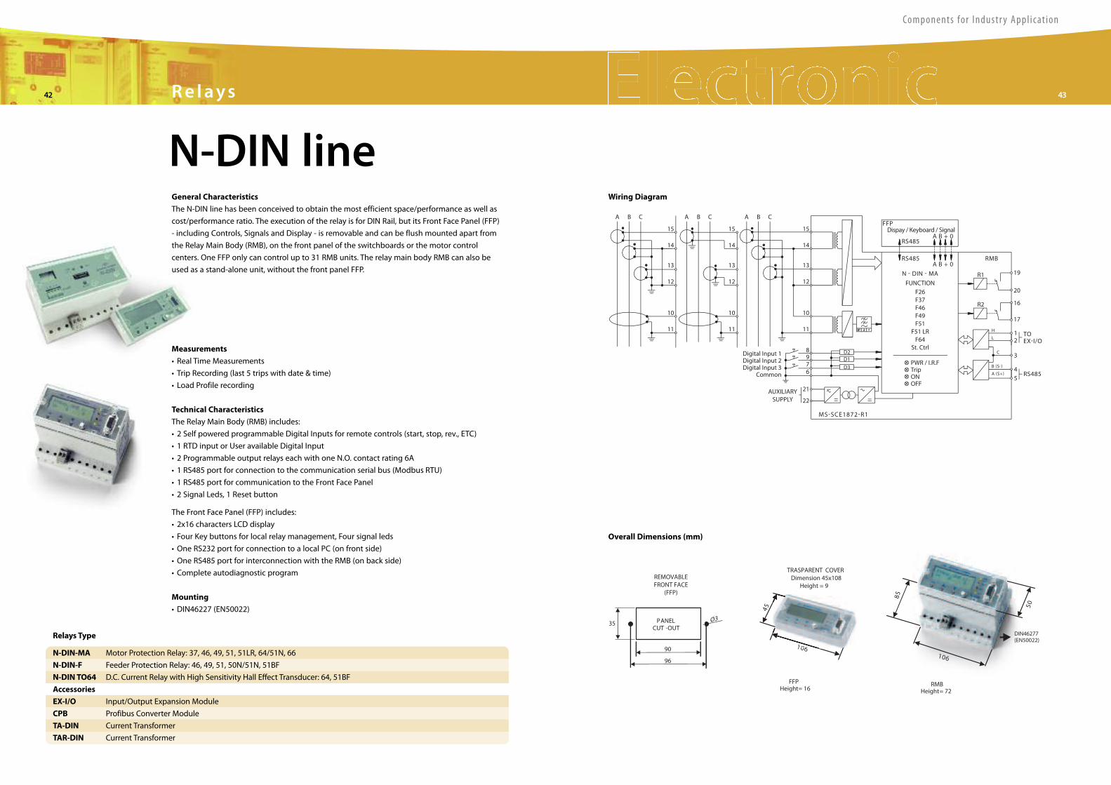
Measurements
• Real Time Measurements
• Trip Recording (last 5 trips with date & time)
• Load Profile recording
Technical Characteristics
The Relay Main Body (RMB) includes:
• 2 Self powered programmable Digital Inputs for remote controls (start, stop, rev., ETC)
• 1 RTD input or User available Digital Input
• 2 Programmable output relays each with one N.O. contact rating 6A
• 1 RS485 port for connection to the communication serial bus (Modbus RTU)
• 1 RS485 port for communication to the Front Face Panel
• 2 Signal Leds, 1 Reset button
The Front Face Panel (FFP) includes:
• 2x16 characters LCD display
• Four Key buttons for local relay management, Four signal leds
• One RS232 port for connection to a local PC (on front side)
• One RS485 port for interconnection with the RMB (on back side)
• Complete autodiagnostic program
Mounting
• DIN46227 (EN50022)
A B C
15
14
13
12
10
11
15
14
13
12
10
11
15
14
13
12
10
11
8976
21
22
A B C A B C
Digital Input 1Digital Input 2Digital Input 3
Common
AUXILIARYSUPPLY
MS-SCE1872-R1
D3
D2D1
RS485A B + 0
A B + 0
FFPDispay / Keyboard / Signal
RS485 RMB
RS485
TOEX-I/O
FUNCTION
PWR / I.R.FTripONOFF
F26F37F46F49F51
F51 LRF64
St. Ctrl
N - DIN - MA R1
R2
19
20
16
17
12
3
45
B (S-)
A (S+)
H
L
C
Wiring Diagram
N-DIN-MA Motor Protection Relay: 37, 46, 49, 51, 51LR, 64/51N, 66
N-DIN-F Feeder Protection Relay: 46, 49, 51, 50N/51N, 51BF
N-DIN TO64 D.C. Current Relay with High Sensitivity Hall Effect Transducer: 64, 51BF
Accessories
EX-I/O Input/Output Expansion Module
CPB Profibus Converter Module
TA-DIN Current Transformer
TAR-DIN Current Transformer
Relays Type
96
35 O3
90
PANELCUT -OUT
DIN46277(EN50022)
FFPHeight= 16
45
1 60
85
50
RMBHeight= 72
TRASPARENT COVERDimension 45x108
Height = 9REMOVABLEFRONT FACE
(FFP)
1 60
610
Overall Dimensions (mm)
N-DIN lineGeneral Characteristics
The N-DIN line has been conceived to obtain the most efficient space/performance as well as
cost/performance ratio. The execution of the relay is for DIN Rail, but its Front Face Panel (FFP)
- including Controls, Signals and Display - is removable and can be flush mounted apart from
the Relay Main Body (RMB), on the front panel of the switchboards or the motor control
centers. One FFP only can control up to 31 RMB units. The relay main body RMB can also be
used as a stand-alone unit, without the front panel FFP.