contactors overload relays - salzer group contactor...contactors overload relays switch onto the...
TRANSCRIPT

www.salzergroup.com
CONTACTORS OVERLOAD RELAYS
Switch on
to the Best
&

Salzer was established in 1985 with German Colloboration for Rotary switches to
bring to the Indian Industry world class technology in Low voltage switchgear
Products, coupled with dependability and excellence in service, to the delight of
all end users.
We seek to understand the requirements of our clients and provide them the
perfect electrical solution. All our ongoing developmental activities for innovative
and value-added products are driven by this sense of responsibility.
With this in mind Salzer now introduces CONTACTORS AND OVERLOAD RELAY to
the Indian and Global market.
Introduction
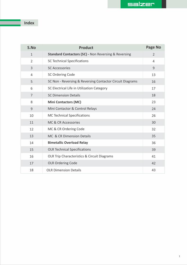
Index
1
S.No Product Page No
1
3
5
7
2
4
6
8
9
10
11
12
13
14
15
16
17
18
Standard Contactors (SC) - Non Reversing & Reversing
SC Technical Specifications
SC Accessories
SC Non - Reversing & Reversing Contactor Circuit Diagrams
SC Dimension Details
SC Ordering Code
SC Electrical Life in Utilization Category
Mini Contactors (MC)
Mini Contactor & Control Relays
MC Technical Specifications
MC & CR Accessories
MC & CR Ordering Code
MC & CR Dimension Details
Bimetallic Overload Relay
OLR Technical Specifications
OLR Trip Characteristics & Circuit Diagrams
OLR Dimension Details
OLR Ordering Code
2
4
9
13
16
17
18
23
24
26
30
32
35
36
39
41
42
43
SC series contactors are ideal for motors, actuator, solenoid and other power switching applications, carries, and
markings which makes them suitable anywhere in the world .
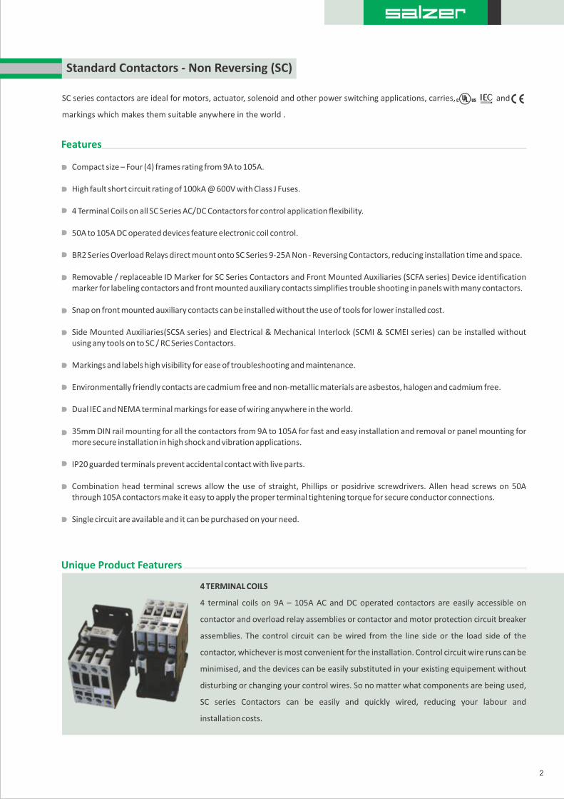
Standard Contactors - Non Reversing (SC)
Features
Compact size – Four (4) frames rating from 9A to 105A.
High fault short circuit rating of 100kA @ 600V with Class J Fuses.
4 Terminal Coils on all SC Series AC/DC Contactors for control application flexibility.
50A to 105A DC operated devices feature electronic coil control.
BR2 Series Overload Relays direct mount onto SC Series 9-25A Non - Reversing Contactors, reducing installation time and space.
Removable / replaceable ID Marker for SC Series Contactors and Front Mounted Auxiliaries (SCFA series) Device identification marker for labeling contactors and front mounted auxiliary contacts simplifies trouble shooting in panels with many contactors.
Snap on front mounted auxiliary contacts can be installed without the use of tools for lower installed cost.
Side Mounted Auxiliaries(SCSA series) and Electrical & Mechanical Interlock (SCMI & SCMEI series) can be installed without using any tools on to SC / RC Series Contactors.
Markings and labels high visibility for ease of troubleshooting and maintenance.
Environmentally friendly contacts are cadmium free and non-metallic materials are asbestos, halogen and cadmium free.
Dual IEC and NEMA terminal markings for ease of wiring anywhere in the world.
35mm DIN rail mounting for all the contactors from 9A to 105A for fast and easy installation and removal or panel mounting for more secure installation in high shock and vibration applications.
IP20 guarded terminals prevent accidental contact with live parts.
Combination head terminal screws allow the use of straight, Phillips or posidrive screwdrivers. Allen head screws on 50A through 105A contactors make it easy to apply the proper terminal tightening torque for secure conductor connections.
Single circuit are available and it can be purchased on your need.
Unique Product Featurers
4 TERMINAL COILS
4 terminal coils on 9A – 105A AC and DC operated contactors are easily accessible on
contactor and overload relay assemblies or contactor and motor protection circuit breaker
assemblies. The control circuit can be wired from the line side or the load side of the
contactor, whichever is most convenient for the installation. Control circuit wire runs can be
minimised, and the devices can be easily substituted in your existing equipement without
disturbing or changing your control wires. So no matter what components are being used,
SC series Contactors can be easily and quickly wired, reducing your labour and
installation costs.
2
RC series contactors are ideal for Reversing motors in applications where panel space is a premium and device modularity is
required to satisfy virtually any application requirement carries and which makes them suitable anywhere in
the world.
RC Reversing Contactors consists of Assembly of Standard Contactors along with interlock & wiring modules, this are assembled in
the form for direct application as Reversing Contactor and to be used in a panel or in an enclosure.
A common mechanical interlock, power wiring modules and IP 20 guarded terminals with dual terminal marking and shared
accessories will help reduce your total installed cost and enhance the features and performance of your equipment.
Features
High fault short circuit rating of 100kA @ 600V with Class J Fuses.
BR2 Series Overload Relays direct mount onto RC Series 9 – 25A Reversing Contactors, reducing installation timeand space.
MP Series Motor Protection Circuit Breakers direct mount onto RC Series 9-40A Reversing AC/DC Contactors AC and DC operating coils for control circuit application flexibility. 50A to 80A DC operated devices featured electronic coil control.
Environmentally friendly contacts are cadmium free and non-metallic materials are asbestos, halogen and cadmium free.
IP20 guarded terminal accidental contacts from live parts.
Dual IEC and NEMA terminal markings for ease of wiring anywhere in the world.
Devices identification marker for labeling contactors and front mounted auxiliary contacts simplifies trouble shooting in panels with many contactors.
Power wiring modules provide reliable, rigid interconnections between the forward and reverse contactors.
Combination head terminal screws allow the use of straight, phillips or posidrive screwdrivers.
Allen head screws on 50A through 80A contactors make it easy to apply the proper terminal tightening torque for secure conductor connections.
Snap-on front mounted auxiliary contacts install without the use of tools for lower installed cost.
Single circuit are available and it can be purchased on your need.
Unique Product Featurers
3
4 TERMINAL COILS
RC series Reversing Contactors feature a single side mounted electrical and mechanical or
mechanical only interlock that is used for the whole range of contactors, enabling a 9A
contactor to be interlocked with a 105A contactor. The side mounted interlock doesn't
increase the depth of the contactor and doesn't prevent front mounted auxiliary contacts
from being added to either the forward or reverse contactors. Contactors are physically
secured together with a dovetail bracket that installs from the bottom of the contactor – so it
can't fall out when it is installed on a DIN rail or on a panel, even in high vibration applications.
Standard Contactors - Reversing (RC)

4
Technical Specifications SC009 SC012 SC018 SC025 SC032 SC040 SC050 SC065 SC080 SC105SC095
Electrical General Units
HzRated operating frequency 25 ~ 400
Impedence per pole 2.35 2.35 2.41 1.65 1.28 0.95 0.85 0.86m 0.86 0.76
Power dissipation per pole
AC - 1 W 1.47 1.47 2.46 3.34 4.6 3.42 6.89 10.4 10.4 14.89 14.89
AC - 3 W 0.19 0.34 0.78 1.03 1.31 1.52 2.12 3.63 5.5 6.86 8.37
Rated coil frequency AC: 50Hz, 60Hz, 50/60Hz and DC
IEC RATING
Rated Insulation voltage, Ui V 1000
Rated Impulse voltage withstand, Uimp KV 6 6 6 6 6 6 8 8 8 8 8
Rated operating voltage, Ue V 690 1000
Rated thermal current, Ith for Ambient Temperature < 55 C
A 25 25 45 45 60 60 90 110 110 140 140
Making Capacity A 300 300 300 450 550 550 1000 1000 1000 1280 1280
Breaking Capacity
Ue = 690V A 130 130 130 170 205 780 780 780 780 950 950
Ue < 400V A 250 250 250 350 450 450 920 920 920 1050
Ue = 500V A 250 250 250 350 450 450 920 920 920 1050
1050
1050
AC-1 Operating Current, Ie
A 25.0 25.0 45.0 45.0 60.0 60.0 90.0 110.0 110.0 140.0 140.0
A 20.0 20.0 32.0 32.0 48.0 48.0 72.0 88.0 88.0 110.0
At 55 C
At 70 C 110.0
AC-3 Operating Current, Ie
A 9.0 12.0 18.0 25.0 32.0 40.0 50.0 65.0 80.0 95.0 105.0380 ~ 400V
A 9.0 12.0 18.0 25.0 32.0 40.0 50.0 65.0 80.0 105.095.0
500V A 7.5 10.5 14.0 19.0 24.0 32.0 38.0 55.0 63.0 85.079.0
660 ~ 690V A 7.0 9.0 13.0 15.0 22.0 25.0 34.0 44.0 48.0 80.060.0
220 ~ 240V
415 ~ 440V A 9.0 12.0 18.0 25.0 32.0 40.0 50.0 65.0 80.0 105.095.0
kW 4.5 6.5 9.2 12.5 15.0 22.0 30.0 37.0 45.0 59.055.0415 ~ 440V
AC-3 OPERATING POWER, Pe
kW 4.0 5.5 7.5 12.5 15.0 18.5380 ~ 400V 22.0 30.0 40.0 55.045.0
kW 2.2 3.0 4.5 6.5 9.2 11.0 15.0 18.5 22.0 30.025.0220 ~ 240V
kW 4.5 6.5 10.0 12.5 15.0 25.0 30.0 40.0 45.0 55.0500V
kW 5.5 7.5 11.0 12.5 18.5 25.0 30.0 45.0 45.0 55.0660 ~ 690V
59.0
65.0
220 ~ 240V
AC-4 Operating Current, Ie
380 ~ 400V A 7.5 10.0 15.0 20.8 26.7 33.3 41.7 54.2 66.7 87.579.2
0.76
A 7.5 10.0 15.0 20.8 26.7 33.3 41.7 54.2 66.7 87.579.2
A 7.55.8 10.8 12.5 18.3 20.8 28.3 36.7 40.0 66.750.0660 ~ 690V
500V A 6.3 8.8 11.7 15.8 20.0 26.7 31.7 45.8 52.5 70.865.8
415 ~ 440V 7.5 10.0 15.0 20.8 26.7 33.3 41.7 54.2 66.7 87.579.2A

5
Technical Specifications (Contd.) SC009 SC012 SC018 SC025 SC032 SC040 SC050 SC065 SC080 SC105SC095
AC-4 Operating Power, Pe
kW 1.5 2.2 4.0 5.5 5.5 7.5 11.0 15.0 18.5 22.022.0220 ~ 240V
3.0 4.0 5.5 7.5 11.0 15.0 22.0 22.0 37.0 45.037.0380 ~ 400V kW
3.0 4.0 5.5 7.5 11.0 15.0 22.0 22.0 37.0 45.037.0415 ~ 440V kW
3.0 4.0 5.5 7.5 11.0 15.0 18.5 30.0 30.0 45.045.0500V kW
4.0 5.5 7.5 7.5 15.0 18.5 22.0 30.0 37.0 55.045.0660 ~ 690V kW
AC-4 Operating Current Ie @ 200,000 Operations
A 2.7 3.6 5.5 7.6 9.7 12.1 15.2 19.7 24.2 28.8 31.8220 ~ 240V
A 2.7 3.6 5.5 7.6 9.7 12.1 15.2 19.7 24.2 28.8 31.8380 ~ 400V
415 ~ 440V A 2.7 3.6 5.5 7.6 9.7 12.1 15.2 19.7 24.2 28.8 31.8
A 2.3 3.2 4.2 5.8 7.3 9.7 11.5 16.7 19.1 23.9 25.8500V
660 ~ 690V A 2.1 2.7 3.9 4.5 6.7 7.6 10.3 13.3 14.5 18.2 24.2
AC-4 Operating Power Pe @ 200,000 Operations
0.55 1.10.75 1.5 2.2 3.0 4.0 4.0 5.5 7.5 7.5220 ~ 240V kW
1.1 1.5 2.2 3.0 4.0 5.5 5.5 7.5 11.0380 ~ 400V kW 11.0 15.0
1.1 1.5 2.2 3.0 4.0 5.5 5.5 7.5 11.0 11.0 15.0415 ~ 440V kW
1.1 1.5 2.2 3.0 4.0 5.5 5.5 7.5 11.0 15.0 15.0500V kW
1.5 1.5 3.0 3.0 5.5 5.5 7.5 11.0 11.0 15.0 22.0660 ~ 690V kW
Short Circuit Coordination
kA 5 10Short Circuit Current Rating
A 25 35 35 50 63 80 100 125 125 160 200Type “2” gL/gG
A 50 50 63 63 100 125Type “1” gL/gG 200200 200 250 250
Rated Short Time Current, ICW
1 second
5 seconds
10 seconds
30 seconds
1 minute
3 minutes
A
A
A
A
A
A
455 455 570 630 1010 1265 1580 2530 2530 3300 3300
205 205 254 280 450 450 710 1130 1130 1485 1485
144 180 200 320 400144 500 800 800 1050 1050
85 85 104 115 185 230 290 460 460 600 600
60
35
60 74 80 130 165 205 325 325 430 430
35 46 50 90 100 120 185 185 250 250
Maximum Electrical Switching Rate
Ops./hr.
1200 1200 1200 1200 1200 1200 1200 1200 600 6001200AC - 1
Ops./hr.
1200 1200 1200 1200 1200 1200 1200 1200 1200 600 600AC - 3
AC - 4Ops./hr.
360 360 360 360 360 200 200 200 200 200 200
Units
Electrical Endurance, AC - 3at Maximum rated 3 PhaseOperating Power @ 400V
1.6 1.8 1.3 1.4 1.3 1.3 1.2 1.4 1.2 1.2 1.0Ops./mill.

6
Technical Specifications (Contd.)SC009 SC012 SC018 SC025 SC032 SC040 SC050 SC065 SC080 SC105SC095
Units
UL Rating
General Purpose Current Rating 25A 25 32 32 60 60 90 110 110 140 140
115V A 9.8 13.8 16.0 24.0 34.0 34.0 34.0 56.0 80.0 80.0 100.0
230V A 10.0 12.0 17.0 17.0 28.0 28.0 40.0 40.0 50.0 68.0 88.0
230V HP 1 1/2 2 3 3 5 5 7 1/2 10 15 15 20
Rated 1 Phase Operating Current, Ie
200V A 11.0 11.0 17.5 25.3 32.2 32.2 48.3 62.1 62.1 78.2 92.0
200V 3.0 3.0 5.0 7 1/2 10.0 10.0 15.0 20.0 20.0 25.0 30.0HP
230V HP 3.0 3.0 5.0 7 1/2 10.0 15.0 15.0 20.0 25.0 30.0 40.0
460V 5.0 7 1/2 10.0 15.0 20.0 30.0 40.0 50.0 50.0 60.0 75.0HP
575V 10.0 15.0 15.0 25.0 25.0 40.0 50.0 60.0 75.0HP 7 1/2 75.0
SCCRs
Standard Fault Test
Short Circuit Current Rating kA 5 10
Maximum Fuse Size A 30 30 60 60 60 60 100 125 150 175 200
High Fault Test
Short Circuit Current Rating kA
Maximum Fuse Size A 25 25 40 40 50 60 90 100 125 150 175
Electrical Endurance
Rated 1 Phase Operating Power, Pe
Rated 3 Phase Operating Power, Pe
A 7.6 11.0 14.0 21.0 27.0 40.0 52.0 65.0 65.0 77.0460V 96.0
115V HP 1/2 3/4 1 2 3 3 3 5 7 1/2 7 1/2 10
Rated 3 Phase Operating Current, Ie
230V A 9.6 9.6 15.2 22.0 28.0 42.0 42.0 54.0 68.0 80.0 104.0
A 9.0 11.0 17.0 17.0 27.0 27.0 41.0 52.0 62.0 77.0 77.0575V
@Maximum rated 3 PhaseOperating Power
Ops.(mill.)
1.8 2.0 1.6 1.6 1.5 1.5 1.6 1.8 1.5 1.5 1.0
100
Coil Characteristics
Rated Insulation Voltage, Ui
Operating Limits50Hz, 60Hz, 50/60Hz
Operating xUc 0.80 ~ 1.10
V 1000
Pick - up xUc 0.60 ~ 0.80 0.65 ~ 0.80
Sealed xUc 0.35 ~ 0.55 0.40 ~ 0.60
DC
xUc 0.80 ~ 1.10Operating
Pickup
xUcSealed
xUc 0.45 ~ 0.65 0.45 ~ 0.75 0.70 ~ 0.80
0.15 ~ 0.30 0.40 ~ 0.600.15 ~ 0.45

7
SC009 SC012 SC018 SC025 SC032 SC040 SC050 SC065 SC080 SC095 SC105
Coil Consumption50Hz, 60Hz, 50/60Hz
Pick - up
Hold - in
VA 70 98 255
VA 7 9 16
Technical Specifications (Contd.)
DC
Pick - up W 5.5 180 340
Hold - in W 5.5 2.2 6.5
Operating Times
AC
Pick - up msec 8 ~ 20 10 ~ 19 15 ~ 30
Drop - out msec 6 ~ 13 5 ~ 25 9 ~ 15
DC
Pick - up 50 ~ 60msec 35 ~ 45 40 ~ 55
Drop - out msec 7 ~ 12 30 ~ 65 55 ~ 60
Power Dissipation 50Hz,60Hz,50/60Hz
W 2.6 4.3
Power factor
Closed
Open
0.33 0.28 0.26
0.84 0.73 0.54
cos
Mechanical
Mechanical EnduranceOps
(mill.) 10
cos
Maximum Mechanical switching rate
Ops/hr
9000.0
Environmental
Ambient Operating Temperature -25 to +55 C (-13 to +131 F)
Ambient Storage Temperature -55 to +80 C (-67 to +176 F)
Construction
Pollution Degree 3
Ingress protection
Main Terminals IP20 IP20*IP20*
Coil Terminals IP20
Auxiliary Terminals IP20
Weight 1.45 1.47Kg 0.295 0.295 0.295 0.295 0.52 1.105 1.12 1.130.52
3.2 3.24Lbs 0.65 0.65 0.650.65 1.15 1.19 2.44 2.47 2.49
RoHS Complaince YesConstruction Conductor cross sectionsMain Terminal Capacity
Solid Stranded without endsleeveAWG WireRecommended strip length
Tightening Torque
2mm
AWGmmin
Nm
lb*in
Screw Driver
2 x 0.5 ~ 6 2 x 1 ~ 16 2 x 1.5 ~ 35
Units
2 x 20 ~ 10
8.55 / 16
1 ~ 1.9
8.8 ~ 16.9
Philips nr.2
2 x 18 ~ 6
103 / 8
2.5 ~ 3.0
22.1 ~ 26.6 35.4 ~ 53.1
4 ~ 6
1 / 213
2 x 16 ~ 2
2 x 1.5 ~ 50
2 x 16 ~ 1.0
159 / 16
5 ~ 6.5
44.3 ~ 57.5
Allen 4mm
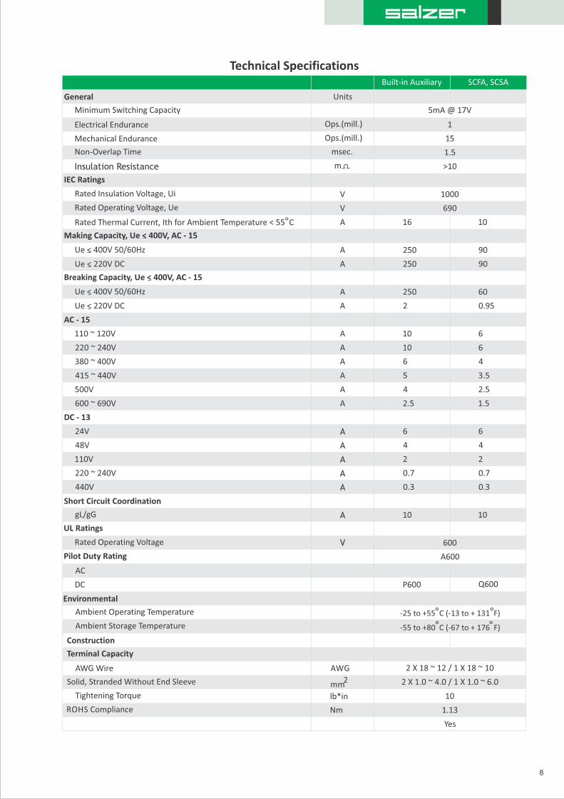
Technical Specifications
8
General
Minimum Switching Capacity
Electrical Endurance
Mechanical Endurance
IEC Ratings
Rated Insulation Voltage, Ui
Rated Operating Voltage, Ue
Rated Thermal Current, Ith for Ambient Temperature < 55 C
Making Capacity, Ue < 400V, AC - 15
Ue < 400V 50/60Hz
Ue < 220V DC
Breaking Capacity, Ue < 400V, AC - 15
Ue < 400V 50/60Hz
Ue < 220V DC
AC - 15
110 ~ 120V
220 ~ 240V
380 ~ 400V
415 ~ 440V
500V
600 ~ 690V
DC - 13
24V
48V
110V
220 ~ 240V
440V
Short Circuit Coordination
gL/gG
UL Ratings
Rated Operating Voltage
Pilot Duty Rating
AC
DC
Environmental
Ambient Operating Temperature
Ambient Storage Temperature
Construction
Terminal Capacity
AWG Wire
Solid, Stranded Without End Sleeve
Tightening Torque
ROHS Compliance
Non-Overlap Time
Insulation Resistance
Built-in Auxiliary SCFA, SCSA
1
15
1.5
>10
5mA @ 17V
msec.
m
Units
Ops.(mill.)
Ops.(mill.)
Yes
V
V
A
A
A
A
A
A
A
A
A
A
A
A
A
A
V
AWG
mm 2
lb*in
Nm
A
A
A
1000
690
600
A600
10
90
90
60
0.95
6
6
4
3.5
2.5
1.5
6
4
2
0.7
0.3
10
Q600
2 X 18 ~ 12 / 1 X 18 ~ 10
10
1.13
2 X 1.0 ~ 4.0 / 1 X 1.0 ~ 6.0
16
250
250
250
2
10
10
6
5
4
2.5
6
4
2
0.7
0.3
10
P600
-25 to +55 C (-13 to + 131 F)
-55 to +80 C (-67 to + 176 F)
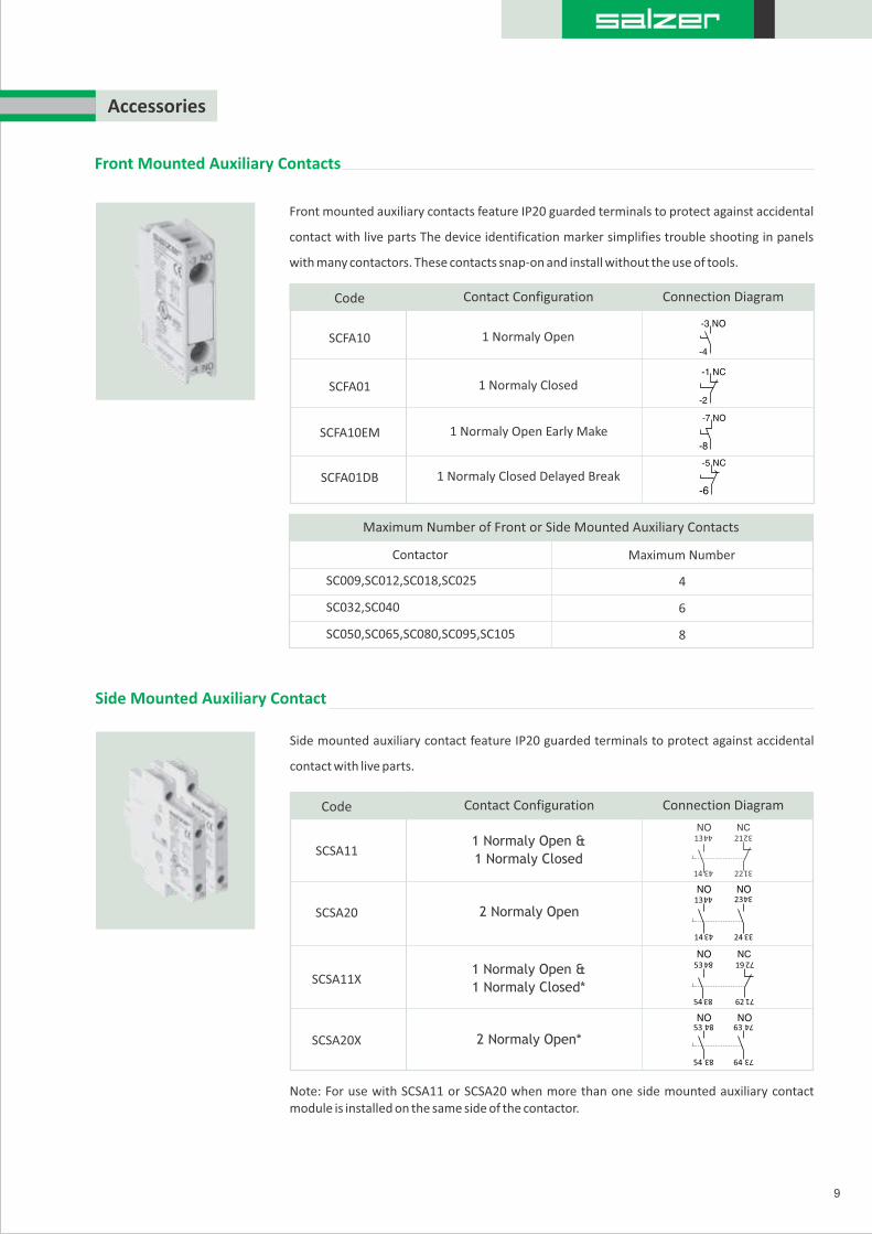
Accessories
Front Mounted Auxiliary Contacts
Side Mounted Auxiliary Contact
Front mounted auxiliary contacts feature IP20 guarded terminals to protect against accidental
contact with live parts The device identification marker simplifies trouble shooting in panels
with many contactors. These contacts snap-on and install without the use of tools.
Contact Configuration Connection Diagram
1 Normaly Open
1 Normaly Closed
1 Normaly Open Early Make
1 Normaly Closed Delayed Break
Code
SCFA10
SCFA01
SCFA10EM
SCFA01DB
9
Side mounted auxiliary contact feature IP20 guarded terminals to protect against accidental
contact with live parts.
SCSA20
SCSA11X
SCSA20X
1 Normaly Open &
1 Normaly Closed
2 Normaly Open
1 Normaly Open &
1 Normaly Closed*
2 Normaly Open*
Note: For use with SCSA11 or SCSA20 when more than one side mounted auxiliary contact module is installed on the same side of the contactor.
SCSA11
Contact Configuration Connection DiagramCode
13
44
21
32
14
43
22
31
13
44
23
34
14
43
24
33
53
84
19
72
62
71
54
83
53
84
63
74
64
73
54
83
Contactor
Maximum Number of Front or Side Mounted Auxiliary Contacts
SC009,SC012,SC018,SC025
SC050,SC065,SC080,SC095,SC105
SC032,SC040
Maximum Number
4
6
8

Electrical & Mechanical Interlock
Electrical / Mechanical interlock for reversing contactors has the same features as the
mechanical interlock but also has two normally closed auxiliaries built into the unit for electrical
interlocking, eliminating the need for two normally closed auxiliary contacts and the
Mechanical Interlock. The result of integrating the normally closed auxiliary contact
is decreased width of reversing contactors and more available auxiliary contact locations.
10
Side mounted mechanical interlock for use with reversing contactors, reversing starters, two
speed starters and star-delta starters. The single interlock can be used with all size contactors
from 9A-105A, Preventing the forward and reverse contactors from being energised at the
same time.
Interlocks
Mechanical Interlock
Wiring Modules
Reversing contactors power wiring modules make field assembly of reversing contactors easy.
Line and load side over molded copper bus bar conductors ensure error free installation and
make a rigid assembly with a mechanical interlock (SCMI) or electrical / mechanical interlock
(SCMEI).
DescriptionCode
For Use With Contactors
SCMI
SCMEI
Side Mounted Mechanical Interlock
Side Mounted Electrical / Mechanical Interlock
SC050,SC065,SC080
SC009,SC012,SC018,SC025
SC032,SC040
Code
SC025RWM1 / SC025RWM2
SC080RWM1 / SC080RWM2
SC040RWM1 / SC040RWM2
Surge Suppressors
Coil mounted surge suppressors protect sensitive electronic components in control circuits
from damaging line voltage spikes.
Code
130 ~ 250V AC
A2
A1
Code Voltage Range
SC105SSDD600 12 ~ 600V DCA2
A1
For Use With Contactor
SC009, SC012,SC018,SC025,SC032,SC040
SC009,SC012,SC018
SC025,SC032,SC040
SC050,SC065,SC080
SC095,SC105
For Use With Contactor
SC009, SC012,SC018,SC025,SC032,SC040
SC050,SC065,SC080,SC095,SC105
SC009, SC012,SC018,SC025,SC032,SC040
SC050,SC065,SC080,SC095,SC105
SC050,SC065,SC080,SC095,SC105
RC Surge Suppressor
Voltage Range
24 ~ 48V AC
50 ~ 127V AC
130 ~ 250V AC
24 ~ 48V AC
50 ~ 127V AC
Diode Surge Suppressor
11
Operating Coils
50Hz
AC Coil Voltage
Voltage
Voltage
60Hz
50/60Hz
Coil Voltage
12 24 48 110 120 208 220 230 240 277 380 400 400~415 440 480 500 550 600
DC Coil Voltage
12 24 24 ~ 28 48 42 ~ 50 110 125 110 ~ 130 250208 ~ 250
SC009 to SC040
SC050 to SC105
SC040SSRA048
SC040SSRA127
SC040SSRA250
SC105SSRA048
SC105SSRA127
SC105SSRA250
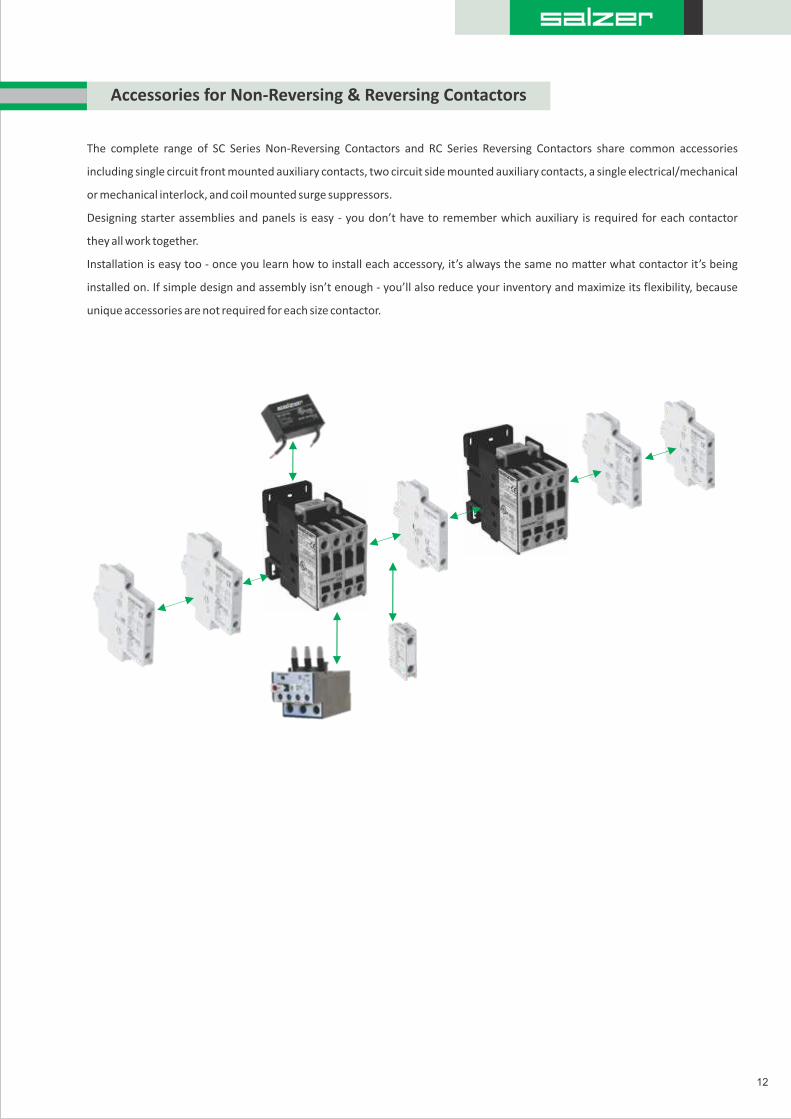
Accessories for Non-Reversing & Reversing Contactors
The complete range of SC Series Non-Reversing Contactors and RC Series Reversing Contactors share common accessories
including single circuit front mounted auxiliary contacts, two circuit side mounted auxiliary contacts, a single electrical/mechanical
or mechanical interlock, and coil mounted surge suppressors.
Designing starter assemblies and panels is easy - you don’t have to remember which auxiliary is required for each contactor
they all work together.
Installation is easy too - once you learn how to install each accessory, it’s always the same no matter what contactor it’s being
installed on. If simple design and assembly isn’t enough - you’ll also reduce your inventory and maximize its flexibility, because
unique accessories are not required for each size contactor.
12

Ordering Code
Non Reversing contactor - Standard contactor 9A to 105A
Contactor
Type
Current
Rating
Normally Open
Poles
Built in
Auxiliary
Contacts
Coil
voltage
type AC/DC
FrequencyCoil
voltage
I IIIII IV V VI VII VIII
Poles
IX
Additional
feature
Example
SC - Standard Contactor
RC - Standard Contactor
I - Contactor Type
009 - 9A
012 - 12A
018 - 18A
025 - 25A
032 - 32A
040 - 40A
050 - 50A
065 - 65A
080 - 80A
105 - 105A
II - Current Rating
III - Poles
IV - Normally Open Poles
Main Poles
20 - 2 Normally Open
02 - 2 Normally Closed
10 - 1 Normally Open
01 - 1 Normally Closed
00 - Aux not provided
For 32A - 105A
Please mention 00 Aux
Not provided
30 - 3 NO (Normally Open)
V - Built in Auxiliary
VI - Coil Voltage Type
A - AC Coil
D -DC Coil
With Wiring Modules for
RC (Reversing Contactors)
VIII - Frequency
F - 50 Hz, S - 60 Hz
B - 50/60Hz
VII - Coil Voltage
AC DC024 24042 42048 48110 110220 220240 240360 360380 380415 415440 440525 525
024 24048 48110 110250 250
S C 0 0 9 P 30 22 A 110 F WW
Note : RC Contactors available upto 80 Amps only
IX
13

Ordering Code - Accessories
Side mounted accessories
SCSA 11
Standard contactor side
mounted auxiliary
10 - 1 normally open
01 - 1 normally closed
20 - 2 normally open
11 - 1 normally open &
1 normally closed * Additional side mounted Acc is to be mounted on same side of contactor
Ordering Informations
SCFA 10
Standard contactor front
mounted auxiliary
EM
Blank - Standard
EM - Early Make
DB - Delay Break
10 - 1 normally open
01 - 1 normally closed
I - Description II - Contact configuration
I - Description
II - Contact configuration
III - Configuration Type
Front Mounted accessories
Interlocks
Ordering Informations
Description
Standard contactor side
mechanical interlock
SCMI
Standard contactor electrical
& Mechanical interlock
with 2 NC Aux
SCMEI
Ordering Informations
I
Contact configuration
II
Description
I IIIII
Configuration TypeDescription Contact configuration
I
14

Ordering Code - Accessories
Ordering Informations
Standard Contactor
025 - SC 009 to SC 025
040 - SC 032 to SC 040
080 - SC 050 to SC 080
I - Type
II - Current Rating
III - Wiring Module
Wiring module
RWM1 - R1 Reversing
Wiring Module
RWM2 - R2 Reversing
Wiring Module
Surge suppressor
Ordering Informations
I III
Standard Contactor
II
SC 040 SSR A 04 8
SSR - Resistor Capacitor type
SSD - Diode type
I - Type
III - Surge Suppressor
V - Voltage Range
IV
IV - Coil Type
I IIIII
Wiring ModuleCurrent RatingContactor Type
SC 025 RWM1
V
Contactor Type Current Rating Capacitor Type Coil Type Voltage Range
040 - SC009 to SC040 Contactor
105 - SC050 to SC105 Contactor
II - Contactor Range
A - AC Coil
D - DC Coil
048 - 24 to 48V
127 - 50 to 127V
250 - 130 to 250V
600 - 12 to 600V
15

Power Circuit Control circuit
M1 = ContactorI = Start Push ButtonO = Emergency Stop Push Button = Coil Voltage Code
M1 = Forward ContactorF = Forward Push ButtonM2 = Reverse ContactorR = Reverse Push Button = Coil Voltage Code = Emergency Stop Push Button
SC Non - Reversing Contactor circuit Diagrams
L1 L2 L3
5L33L21L1
2T1 4T2 6T3
U V W
11
12
13 13
14 14
5L33L21L1
2T1 4T2 6T3 2T1 4T2 6T3
16
Power Circuit
12
13
1413
14
13
1413
14
02A1 02A1
A201 A2M1
M201
R
Control circuit
RC Reversing Contactor circuit Diagrams

To find a Contactor’s Estimated Life:
1. Identify the Utilization Category of the Application.
2. Refer to the chart For the Applicable Utilization category.
3. Locate the Intersection of the Life-load Curve For the Contactor Selected with the Application Breaking Current (Ie) on the Horizontal Axis of the Chart.
4. Read the estimated Contactor Life From the Vertical Axis of the Chart.
The Life -load curves are based on tests in accordancewith IEC 60947-4-1. Many Conditions of an actual application effect contact life such as the environment and duty cycle, therefore, the actual contact life may vary from the life Indicated by the curves shown here.
Electrical Life In Utilization Category
17
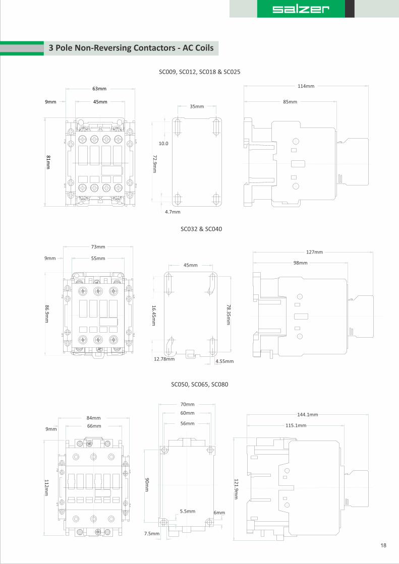
SC009, SC012, SC018 & SC025
SC032 & SC040
SC050, SC065, SC080
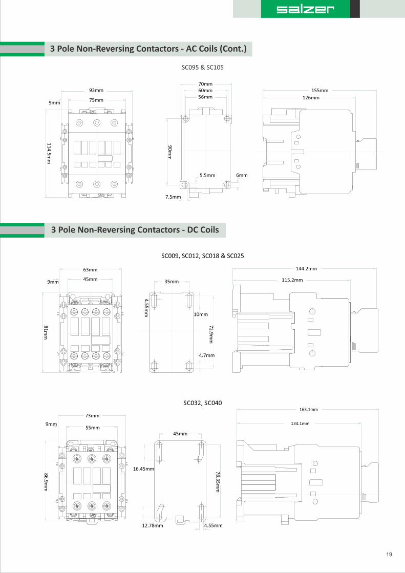
3 Pole Non-Reversing Contactors - AC Coils
18
45mm
78
.35
mm
16
.45
mm
12.78mm 4.55mm
4.7mm
35mm
72
.9m
m
10.0
63mm
45mm9mm
81
mm
114mm
85mm
55mm
73mm
9mm
86
.9m
m
127mm
98mm
70mm
60mm
56mm
90
mm
7.5mm
5.5mm 6mm
9mm66mm
84mm
11
2m
m
12
1.9
mm
115.1mm
144.1mm
SC095 & SC105
3 Pole Non-Reversing Contactors - AC Coils (Cont.)
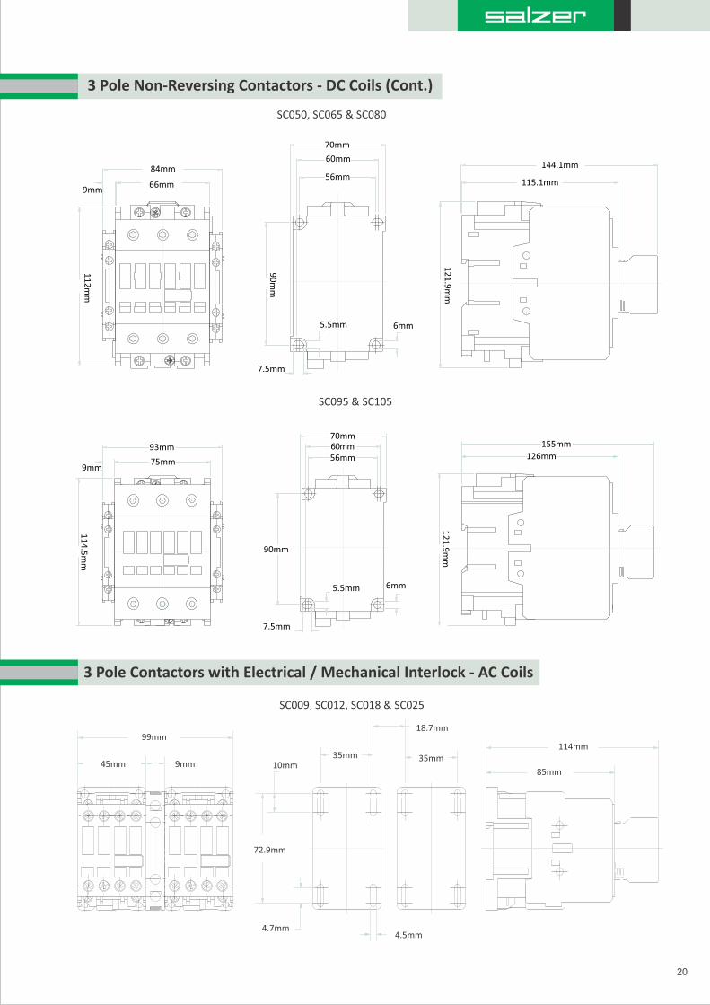
3 Pole Non-Reversing Contactors - DC Coils
19
75mm
93mm
9mm
11
4.5
mm
70mm60mm56mm
90
mm
7.5mm
5.5mm 6mm
126mm
155mm
63mm
45mm9mm
81
mm
72
.9m
m
10mm
4.7mm
35mm
4.5
5m
m
115.2mm
144.2mm
SC009, SC012, SC018 & SC025
16.45mm
12.78mm
45mm
78
.35
mm
4.55mm
134.1mm
163.1mmSC032, SC040
86
.9m
m
55mm
73mm
9mm
114mm
85mm10mm
35mm
18.7mm
35mm
72.9mm
4.7mm4.5mm
99mm
45mm 9mm
9mm66mm
84mm
11
2m
m
3 Pole Non-Reversing Contactors - DC Coils (Cont.)
20
70mm
60mm
56mm
90
mm
7.5mm
5.5mm 6mm
12
1.9
mm
115.1mm
144.1mm
SC050, SC065 & SC080
SC095 & SC105
75mm
93mm
9mm
11
4.5
mm
70mm60mm56mm
90mm
7.5mm
5.5mm 6mm
3 Pole Contactors with Electrical / Mechanical Interlock - AC Coils
SC009, SC012, SC018 & SC025
126mm
155mm
12
1.9
mm

70mm60mm
56mm
90
mm
7.5mm
5.5mm6mm
17mm
3 Pole Contactors with Electrical / Mechanical Interlock - AC Coils (Cont.)
21
86
.9m
m
55mm
119mm
9mm44.95mm19.05mm
16.45mm
12.78mm
44.95mm
4.55mm
78
.35
mm
98mm
89
.35
mm
127mm
66mm
11
2m
m
9mm
141mm
12
1.9
mm
115.1mm
144.1mm
75mm159mm
11
4.5
mm
9mm
70mm60mm56mm
90
mm
7.5mm
5.5mm 6mm
26mm
125.6mm154.6mm
12
1.9
mm
SC095 & SC105
SC050, SC065 & SC080
SC032 & SC040
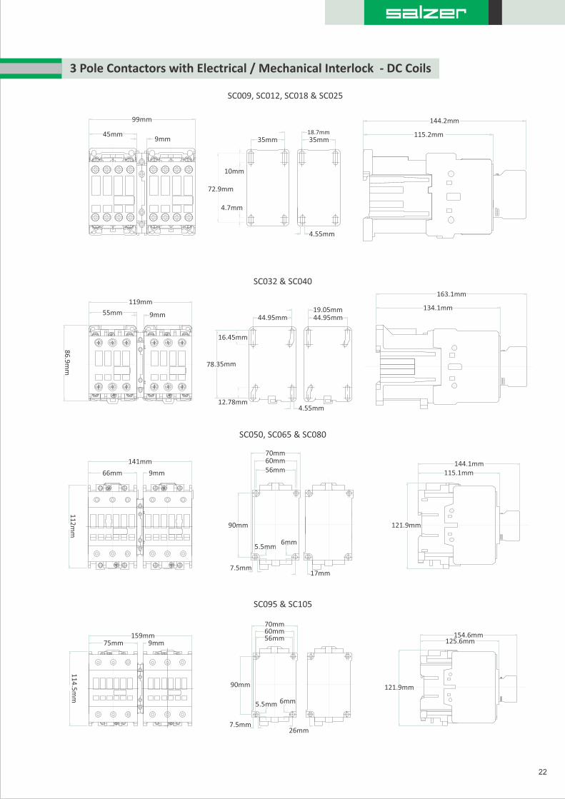
3 Pole Contactors with Electrical / Mechanical Interlock - DC Coils
22
SC009, SC012, SC018 & SC025
115.2mm
144.2mm
45mm
99mm
9mm 35mm
72.9mm
10mm
4.7mm
4.55mm
35mm18.7mm
SC032 & SC040
55mm
119mm
86
.9m
m
9mm 44.95mm
16.45mm
12.78mm4.55mm
78.35mm
44.95mm19.05mm 134.1mm
163.1mm
66mm
11
2m
m
9mm
141mm
115.1mm144.1mm
70mm60mm56mm
90mm
7.5mm
5.5mm6mm
17mm
75mm159mm
11
4.5
mm
9mm
70mm60mm56mm
90mm
7.5mm
6mm
26mm
125.6mm154.6mm
121.9mm
SC050, SC065 & SC080
SC095 & SC105
121.9mm
5.5mm
23
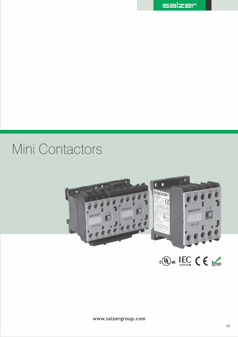
Mini Contactors
www.salzergroup.com

Salzer Mini Contactors and Control Relays are compact family of control devices for
switching motors and other logic control circuits. MR Series Mini Reversing Contactors are
ideal for reversing motors in applications where panel space is a premium and device
modularity is required to satisfy virtually any application requirement. Common accessories
enable the devices to be customized for each application. For motor overload protection,
Overload Relays can be directly mounted to mini contactors.
Mini Contactors and Control Relays
Product features include
24
High fault short circuit rating of 100kA @ 600V with Class J Fuses .
Removable / replaceable ID Marker for MC Series Contactors and CR Series Control Relay, Device identification marker for labeling
contactors and front mounted auxiliary contacts simplifies trouble shooting in panels with many contactors.
MP Series Motor Protection Circuit Breakers direct mount onto MR Series Reversing AC/DC Contactors.
Markings and labels, high visibility label for ease of troubleshooting and maintenance
Compact size – one frame size for devices rated up to 16A.
AC and DC operating coils for control circuit application flexibility – device is the same physical size with an AC or DC coil.
Modular design and common snap-on accessories are easily installed without the use of tools, lowering assembly
and installation costs.
Front Mounted auxiliary contacts and surge suppressors install directly on top of the single front mounted mechanical interlock
when used with our Mini reversing contactor.
Miniature contactors compatible with directly mounted BR1 series overload Relays with current ratings from 0.28 to 17A.
Over load relays are Class 10 with selectable manual or automatic reset, and provide phase loss sensitivity.
IP20 guarded terminals with dual terminal markings prevent accidental contact with live parts.
Device identification marker for labelling the contactor or control relay simplifies trouble shooting in panels with many devices.
Universal ratings and markings: A, kW and HP rating as well as applicable 3rd party certification markings.
35mm DIN rail mounting for fast and easy installation and removal without the use of tools, panel mounting for more secure
installation in high shock and vibration applications. Mini Non-Reversing contactors and Control Relays feature printed circuit
board mounting with an accessory link module.
Control relay includes bifurcated contacts rated 16A, AC-1,A600, and Q600 for high switching applications upto 600V.
Four pole control relay with NO and NC contact configuration.

The Printed Circuit Board Link Module installs directly on the
Terminals of mini contactors and control relays enabling them to be
directly mounted on an electronic printed circuit board. The module
is rated 16A AC-3 and 22A AC-1 to take full advantage of the maximum
switching capability of the mini contactor and control relay.
The insulated, wiring modules provide error free interconnections
for reversing the power poles, and provide the electrical interlock
through the integrated normally closed auxiliary contacts.
Unique Product Feature
Mini Control Relays
25
Mini Control Relays
Code Description
CR016P00 Four Pole Control Relay 16A AC~1, A600,Q600
Contact Ratings
Contact Configuration
Code
22
31
40
13
04
Description
2 NO and 2 NC
3 NO and 1 NC
4 NO
1 NO and 3 NC
4 NC
AC Coil Voltage
Voltage
Coil Voltage
50Hz
24 48 110 120 230 240 480 600400
DC Coil Voltage
12 24 110 125 250Voltage
60Hz
50/60Hz
26
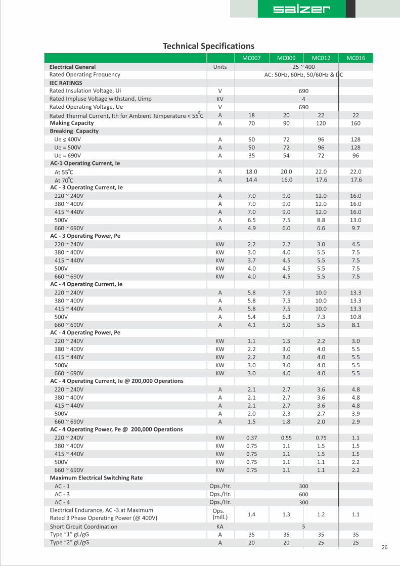
AC: 50Hz, 60Hz, 50/60Hz & DCUnits
MC007 MC009 MC012 MC016
Electrical General 25 ~ 400Rated Operating Frequency
IEC RATINGSRated Insulation Voltage, Ui V 690Rated Impluse Voltage withstand, Uimp KV 4Rated Operating Voltage, Ue V 690
Rated Thermal Current, Ith for Ambient Temperature < 55 C A 18 20 22 22Making Capacity A 70 90 120 160Breaking Capacity
Ue < 400V A 50 72 96 128
Ue = 500V A 50 72 96 128
Ue = 690V A 35 54 72 96AC-1 Operating Current, Ie
At 55 C 18.0 20.0 22.0 22.0A
At 70 C 14.4 16.0 17.6 17.6AAC - 3 Operating Current, Ie
220 ~ 240V A 7.0 9.0 12.0 16.0
380 ~ 400V A 7.0 9.0 12.0 16.0
415 ~ 440V A 7.0 9.0 12.0 16.0
500V A 6.5 7.5 8.8 13.0
660 ~ 690V A 4.9 6.0 6.6 9.7AC - 3 Operating Power, Pe
220 ~ 240V KW 2.2 2.2 3.0 4.5
380 ~ 400V KW 3.0 4.0 5.5 7.5
415 ~ 440V KW 3.7 4.5 5.5 7.5
500V KW 4.0 4.5 5.5 7.5
660 ~ 690V KW 4.0 4.5 5.5 7.5AC - 4 Operating Current, Ie
220 ~ 240V A 5.8 7.5 10.0 13.3
380 ~ 400V A 5.8 7.5 10.0 13.3
415 ~ 440V A 5.8 7.5 10.0 13.3
500V A 5.4 6.3 7.3 10.8
660 ~ 690V A 4.1 5.0 5.5 8.1AC - 4 Operating Power, Pe
220 ~ 240V KW 1.1 1.5 2.2 3.0
380 ~ 400V KW 2.2 3.0 4.0 5.5
415 ~ 440V KW 2.2 3.0 4.0 5.5
500V KW 3.0 3.0 4.0 5.5
660 ~ 690V KW 4.03.0 4.0 5.5AC - 4 Operating Current, Ie @ 200,000 Operations
A 2.1 2.7 3.6 4.8220 ~ 240V
A 2.1 2.7 3.6 4.8380 ~ 400V
A 2.1 2.7 3.6 4.8415 ~ 440V
A 2.0 2.3 2.7 3.9500V
A 1.5 1.8 2.0 2.9660 ~ 690VAC - 4 Operating Power, Pe @ 200,000 Operations
220 ~ 240V KW 0.37 0.55 0.75 1.1
KW 0.75 1.1 1.5 1.5380 ~ 400V
KW 0.75 1.1 1.5 1.5415 ~ 440V
KW 0.75 1.1 1.1 2.2500V
660 ~ 690V KW 1.10.75 1.1 2.2
Maximum Electrical Switching Rate
AC - 1 Ops./Hr. 300
AC - 3 Ops./Hr. 600
AC - 4 300Ops./Hr.
Electrical Endurance, AC -3 at Maximum Rated 3 Phase Operating Power (@ 400V)
Ops.(mill.) 1.4 1.3 1.2 1.1
Short Circuit Coordination KA 5
Type “1” gL/gG A 35 35 35 35
2020 25 25AType “2” gL/gG
Technical Specifications
27
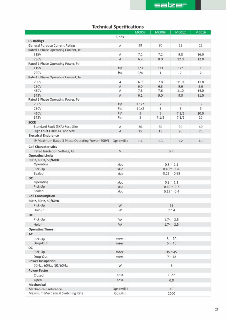
Technical Specifications
A 18 20 22 22General Purpose Current Rating
Rated 1 Phase Operating Power, Pe
230V Hp 3/4 1 2 2
200V
460V
A 6.9 7.8 11.0 11.0
A 7.6 7.6 11.0 14.0
Rated 3 Phase Operating Power, Pe
230V
575V
Hp 1 1/2 3 3 5
Hp 5 7 1/2 7 1/2 10
Standard Fault (5KA) Fuse Size A 30 30 30 40
Electrical Endurance
Coil Characteristics
Operating Limits
Operating
Sealed
xUc
xUc
0.8 ~ 1.1
0.25 ~ 0.65
Operating
Sealed
xUc
xUc
0.8 ~ 1.1
0.15 ~ 0.4
50Hz, 60Hz, 50/60Hz
Hold-In W 2 ~ 4
Pick-Up VA 1.74 ~ 2.5
Operating Times
Pick-Up msec. 8 ~ 20
DC
Drop-Out msec. 7 ~ 12
50Hz, 60Hz, 50/60Hz 3W
0.27
UL Ratings
Closed
0.8
cos
cos
Power Factor
Power Dissipation
Pick-Up msec. 35 ~ 45
Drop-Out msec. 6 ~ 13
AC
Hold-In VA 1.74 ~ 2.5
DC
Pick-Up W 16
Coil Consumption
Pick-Up xUc 0.40 ~ 0.7
DC
Pick-Up xUc 0.40 ~ 0.76
50Hz, 60Hz, 50/60Hz
Rated Insulation Voltage, Ui V 690
@ Maximum Rated 3 Phase Operating Power (400V) Ops.(mill.) 1.4 1.3 1.2 1.1
High Fault (100KA) Fuse Size A 15 15 20 25
SCCR
460V Hp 5 5 7 1/2 10.0
200V Hp 1 1/2 2 3 3
575V A 6.1 9.0 9.0 11.0
230V A 6.0 6.8 9.6 9.6
Rated 3 Phase Operating Current, Ie
115V Hp 1/3 1/3 1/2 1
230V
115V A 7.2 7.2 9.8 16.0
A 6.9 8.0 12.0 12.0
Rated 1 Phase Operating Current, Ie
MC007 MC009 MC012 MC016
Open
MechanicalMechanical Endurance Ops.(mill.)Maximum Mechanical Switching Rate Ops./Hr.
102000
Units

28
MC007 MC009 MC012 MC016
Units
A
A
A
A
10 X le (AC-15)
6.0
4.0
4.0
0.7
10
5.0
4.0
0.4
A
DC Q600
2
Nm
V 690
A 16
-55 to +80 C (-67 to +176 F)
-25 to +55 C (-13 to +131 F)
Ib*in
mmmm2
2 X 0.5 ~ 2.5
1 ~ 1.28.8 ~ 10.6
2 X 0.5 ~ 2.5
2 X 20 ~ 14AWG
Ops.(mill.) 10
AC A600
V 600
A 10
Built-in AuxiliaryControl Relay (CR016)
Auxiliary Contact Specifications
A 0.35 0.2
A 1.5
A 6.0
A
A 5.0 5.0
A 10.0
A 10 X le (AC-15) 30.0
A 10
V 690
Making Capacity, Ue < 400V, AC-15 Breaking Capacity, Ue < 400V, AC-15AC-15
380 ~ 400V< 240V
415 ~ 440V500V660 ~ 690V
DC-1324V48V60V110V220 ~ 240V
gL/gG
Environmental
Ambient Storage Temperature
Terminal Capacity
Tightening Torque
Short Circuit Coordination
UL RatingsRated Voltage, UePilot Duty Rating
Electrical Endurance
Solid
Rated insulation Voltage, Ui
AC-1 Ratings @ 230V (C016 only)
IEC RATINGS
Mechanical
Ambient Operating Temperature
Construction
AWG Wire
Stranded
Mechanical Endurance
Rated Operating Voltage, Ue
Rated Thermal Current, Ith for Ambient Temperature < 55 C
MCFA, CRFA
-10
10.0
1.5-
0.5
10
Technical Specifications
Environmental
-25 to +55 C (-13 to +131 F)Ambient Operating Temperature
-55 to +80 C (-67 to +176 F)Ambient Storage Temperature
Construction
Ingress Protection
Main Circuits IP20
IP20Control Circuit Terminations
Weight 0.18Kg.
lbs. 0.4
Terminal Capacity
AWG Wire AWG 2 X 20 ~ 14
Solid mm2 1 X 0.5 ~ 2.5
Stranded mm2 1 X 0.5 ~ 2.5
Tightening Torque Nm 1 ~ 1.2
Ib*in 8.8 ~ 10.6
2.0 -
Ops.(mill.) 1.0
29
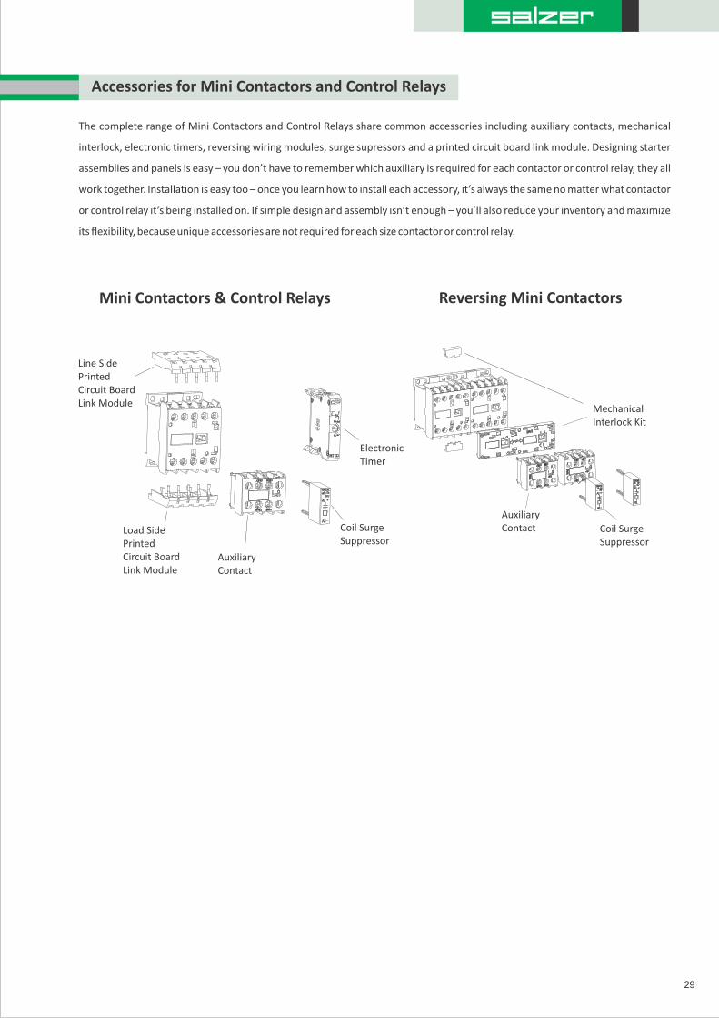
The complete range of Mini Contactors and Control Relays share common accessories including auxiliary contacts, mechanical
interlock, electronic timers, reversing wiring modules, surge supressors and a printed circuit board link module. Designing starter
assemblies and panels is easy – you don’t have to remember which auxiliary is required for each contactor or control relay, they all
work together. Installation is easy too – once you learn how to install each accessory, it’s always the same no matter what contactor
or control relay it’s being installed on. If simple design and assembly isn’t enough – you’ll also reduce your inventory and maximize
its flexibility, because unique accessories are not required for each size contactor or control relay.
Accessories for Mini Contactors and Control Relays
Mini Contactors & Control Relays Reversing Mini Contactors
Line Side Printed Circuit Board Link Module
Load Side Printed Circuit Board Link Module
Auxiliary Contact
Coil Surge Suppressor
Electronic Timer
Mechanical Interlock Kit
Coil Surge Suppressor
Auxiliary Contact
30
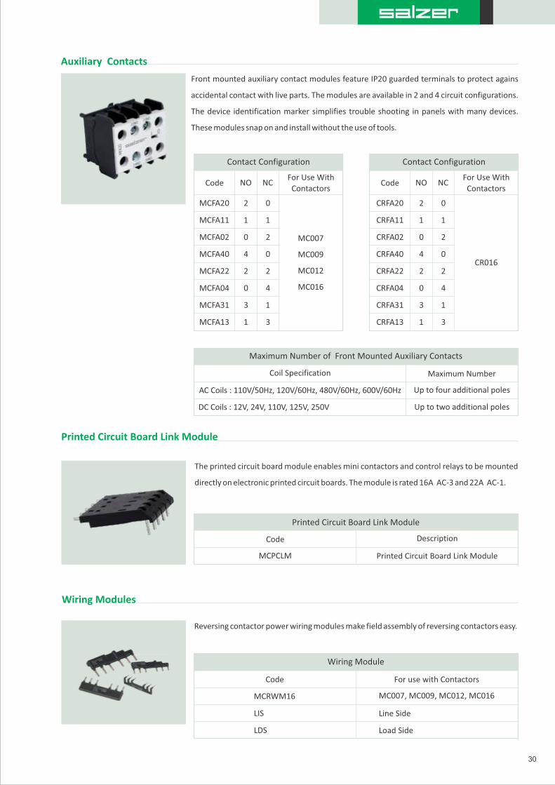
Front mounted auxiliary contact modules feature IP20 guarded terminals to protect agains
accidental contact with live parts. The modules are available in 2 and 4 circuit configurations.
The device identification marker simplifies trouble shooting in panels with many devices.
These modules snap on and install without the use of tools.
Auxiliary Contacts
Contact Configuration
Code NO NCFor Use With
Contactors
CRFA11
CRFA02
CRFA40
CRFA22
CRFA04
CRFA31
CRFA13
Maximum Number of Front Mounted Auxiliary Contacts
AC Coils : 110V/50Hz, 120V/60Hz, 480V/60Hz, 600V/60Hz
Printed Circuit Board Link Module
The printed circuit board module enables mini contactors and control relays to be mounted
directly on electronic printed circuit boards. The module is rated 16A AC-3 and 22A AC-1.
Reversing contactor power wiring modules make field assembly of reversing contactors easy.
Wiring Modules
Wiring Module
Code Description
1
2
0
0
1
0
4
2
2
0
3
1
2
4
1
3
MCFA04
MCFA31
MCFA13
MCFA11
MCFA02
MCFA40
MCFA20
MCFA22
MC007
MC009
MC012
MC016
Contact Configuration
Code NO NCFor Use With
Contactors
1
2
0
0
1
0
4
2
2
0
3
1
2
4
1
3
CRFA20
CR016
Maximum Number
Up to four additional poles
Up to two additional poles
Coil Specification
DC Coils : 12V, 24V, 110V, 125V, 250V
Printed Circuit Board Link Module
MCPCLM Printed Circuit Board Link Module
Code For use with Contactors
MC007, MC009, MC012, MC016
Line Side
Load Side
LIS
LDS
MCRWM16
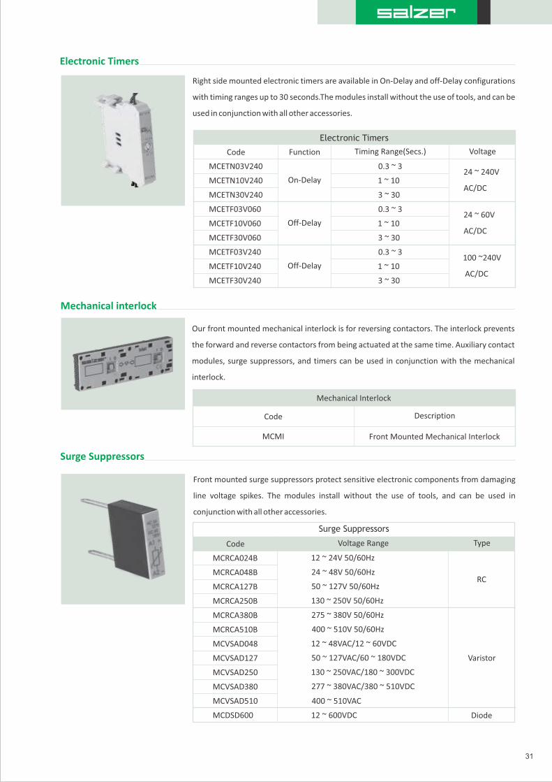
Our front mounted mechanical interlock is for reversing contactors. The interlock prevents
the forward and reverse contactors from being actuated at the same time. Auxiliary contact
modules, surge suppressors, and timers can be used in conjunction with the mechanical
interlock.
Mechanical interlock
Right side mounted electronic timers are available in On-Delay and off-Delay configurations
with timing ranges up to 30 seconds.The modules install without the use of tools, and can be
used in conjunction with all other accessories.
Electronic Timers
Front mounted surge suppressors protect sensitive electronic components from damaging
line voltage spikes. The modules install without the use of tools, and can be used in
conjunction with all other accessories.
Surge Suppressors
31
Electronic Timers
Mechanical Interlock
Surge Suppressors
Code Function Timing Range(Secs.) Voltage
On-Delay
Off-Delay
Off-Delay
0.3 ~ 3
1 ~ 10
3 ~ 30
0.3 ~ 3
1 ~ 10
3 ~ 30
0.3 ~ 3
1 ~ 10
3 ~ 30
24 ~ 240V
AC/DC
24 ~ 60V
AC/DC
100 ~240V
AC/DC
MCETN03V240
MCETN10V240
MCETN30V240
MCETF03V060
MCETF10V060
MCETF30V060
MCETF03V240
MCETF10V240
MCETF30V240
Description
Front Mounted Mechanical Interlock
Code
MCMI
MCRCA024B
MCRCA048B
MCRCA127B
MCRCA250B
MCRCA380B
MCRCA510B
MCVSAD048
MCVSAD127
MCVSAD250
MCVSAD380
MCVSAD510
MCDSD600
12 ~ 24V 50/60Hz
12 ~ 48VAC/12 ~ 60VDC
50 ~ 127VAC/60 ~ 180VDC
130 ~ 250VAC/180 ~ 300VDC
277 ~ 380VAC/380 ~ 510VDC
24 ~ 48V 50/60Hz
50 ~ 127V 50/60Hz
130 ~ 250V 50/60Hz
275 ~ 380V 50/60Hz
400 ~ 510V 50/60Hz
400 ~ 510VAC
12 ~ 600VDC
Type
RC
Varistor
Diode
Voltage Range Code

Mini Contactors
32
Ordering Informations
Ordering Code
I - Type
MC - Mini Non - Reversing Contactor
MR - Mini Reversing Contactor
II - Ampere Rating
III - Letter P
IV - Pole Configuration
20 - 2 normally open 02 - 2 normally closed 22 -2 normally open & 2 normally closed 13 - 1 normally open & 3 normally closed 31 - 3 normally open & 1 normally closed 30 - 3 normally open 40 - 4 normally open 04 - 4 normally closed
VI - Coil type
V - Auxiliary Pole Configuration
00 - No auxiliary 01 - 1 normally closed 10 -1 normally open 11 - 1 normally open & 1 normally closed 20 - 2 normally open 02 - 2 normally closed
IXI II III IV V VI VII VIII
PolesContactor
Type
Current
Rating
Main Pole
Configuration
Inbuilt Conatct
Configuration
Coil
VoltageFrequency
MC 0 0 7 P 30 10 A 2 30 B
Coil TypeAdditional
Feature
007 - 7A 009 - 9A 012 - 12A 016 - 16A
P = Main Poles
VIII - Frequency range
F - 50Hz, S - 60Hz, B - 50/60Hz
AC DC024 24
048 48110 110120 120230 230240 240400 400480 480600 600
012 12024 24110 110125 125250 250
A -AC voltage coil D- DC voltage coil M - Multiple voltage AC coils
VII - Coil Voltage
IX - Additional Feature
With Wiring Module for MR(Reversing Contactor)
WW
Mechanical Interlock
Ordering Informations
II - InterlockMC MII - Contactor
MC - Mini Contactor
II
InterlockType
I
MI - Mechanical Interlock

MC LIS RWM16I - Type
MC - Mini Contactor
III -Configuration
II -Modules
LIS - Line Side
LDS - Load Side
Reversing Wiring Module
Ordering Code - Accessories
33
Auxiliary Contact
Ordering Informations
MC FA 40
I - Type
MC -Mini Contactor
CR - Mini control relay
II - Accessories
FA - Front Mounted Accessories
III - Configuration
20 - 2 normally open contacts
11 - 1 normally open & 1 normally closed contact
02 - 2 normally closed contacts
40 - 4 normally open contacts
22 - 2 normally open & 2 normally closed contacts
04 - 4 normally closed contacts
31 - 3 normally open & 1 closed contacts
13 - 1 normally open & 3 normally closed contacts
Electronic Timer
III
Time
MC TDD 10 AD 060I - Type
MC -Mini Contactor
II - Type
TED - On - Delay
TDD - Off - Delay
III - Time (Sec)
03 - 0.3 ~ 3 sec 10 - 1 ~ 10 sec 30 - 3 ~ 30 sec
IV - Voltage type
V - Voltage Range
III
Contact configuration
II
Front Mounted AuxiliaryType
I
Type
I II
Time Type
IV
Voltage Type
V
Voltage Range
240 (if TED) 24 ~ 240V AC/DC 060 (if TDD) 24 ~ 60V AC/DC 240 (if TDD) 100 ~ 240V AC/DC
A - AC Voltage, D - DC Voltage
AD - both AC & DC Voltage
Wiring Module
II
RWM16MC
I III
LIS or LDS
Ordering Informations
Ordering Informations
Printed Circuit Board Link Module
MC
II
PCLM16
Ordering Informations
I
MC PC LMI - Type II - Module Type
MC - Mini Contactor PCLM16 - Printed circuit board Link module

Mini Control Relay
34
Ordering Code - Accessories
Ordering Informations
I - Type
CR - Mini control relay
016 - Model
II - Model Type
P denotes poles
III - Letter P
C R 016 P 00 A 230 B40
V - Pole Configuration00 - No main poles
IV - Main Poles
VI - Coil Type
VII - Coil Voltage
VIII - Frequency range
22 - 2 normally open & 2 normally closed 31 - 3 normally open & 1 normally closed 40 - 4 normally open 13 - 1 normally open & 3 normally closed 04 - 4 normally closed
I II V VI VIIIII IV
Frequency
Range
VIII
Type Current Coil Type Coil VoltagePAuxiliary Pole
Configuration
Main Pole
Configuration
F - 50Hz S - 60Hz B - 50/60Hz
230 - Voltage
A - AC Voltage CoilD - DC Voltage CoilM - Multipl Voltage AC Coil
Mini Contactor Surge Suppressor
Ordering Informations
I II VIII IV
Type Model Voltage Type Frequency RangeVoltage Range
I - Type
MCSS - Mini Contactor Surge Suppressor
RC - Resistor Capacitor typeVS - Varistor typeDS - Diode type
II - Model Type
A - AC VoltageD - DC VoltageM - Both AC & DC Voltage
III - Voltage Type
MC RC A 127 B
IV - Voltage Range
V - Frequency Range
F - 50Hz
S - 60Hz
B - 50/60Hz
024 - 12 ~ 24V 50/60Hz
048 - 24 ~ 48V 50/60Hz
127 - 48 ~ 127V 50/60Hz
250 - 127 ~ 250V 50/60Hz
380 - 250 ~ 380V 50/60Hz
510 - 380 ~ 510V 50/60Hz
048 - 12 ~ 48VAC / 12 - 60VDC
127 - 50 ~ 127VAC / 60 - 180VDC
275 - 130 ~ 275VAC / 180 - 300VDC
380 - 277 ~ 380VAC / 300 - 510VDC
510 - 400 ~ 510VAC
600 - 12 ~ 600VDC
45.00mm
11
9.3
2m
m
2T1 4T2 6T3 22NC A2-
1L1 3L2 5L3 21NC A1+
19mm 18mm
25.55mm 25.55mm
5.43mm
3.43mm 3.43mm
4.43mm
58
mm
82mm
60.90mm
51.75mm
58.75mm
85.40mm
A1+ 1L1 3L2 5L3 21NC A1+ 1L1 3L2 5L3 21NC
2T1 4T2 6T3 22NC A2- 2T1 4T2 6T3 22NC A2-
90.00mm
Ø1.85mm
62
.3m
m
31.15mm
8.50mm
Electronic Timer
Printed Circuit Board Link Modules
2T1 4T2 6T3 22NC A2-
1L1 3L2 5L3 21NC A1+
9.00mm
45.00mm
66
.65
mm
5.83mm52.15mm
35
19mm18mm
25.55mm 25.55mm
5.43mm
3.43mm 3.43mm
4.43mm
78.4mm
51.75mm1L1 3L2 5L3 21NC A1+
2T1 4T2 6T3 22NC A2-
45mm
58
mm
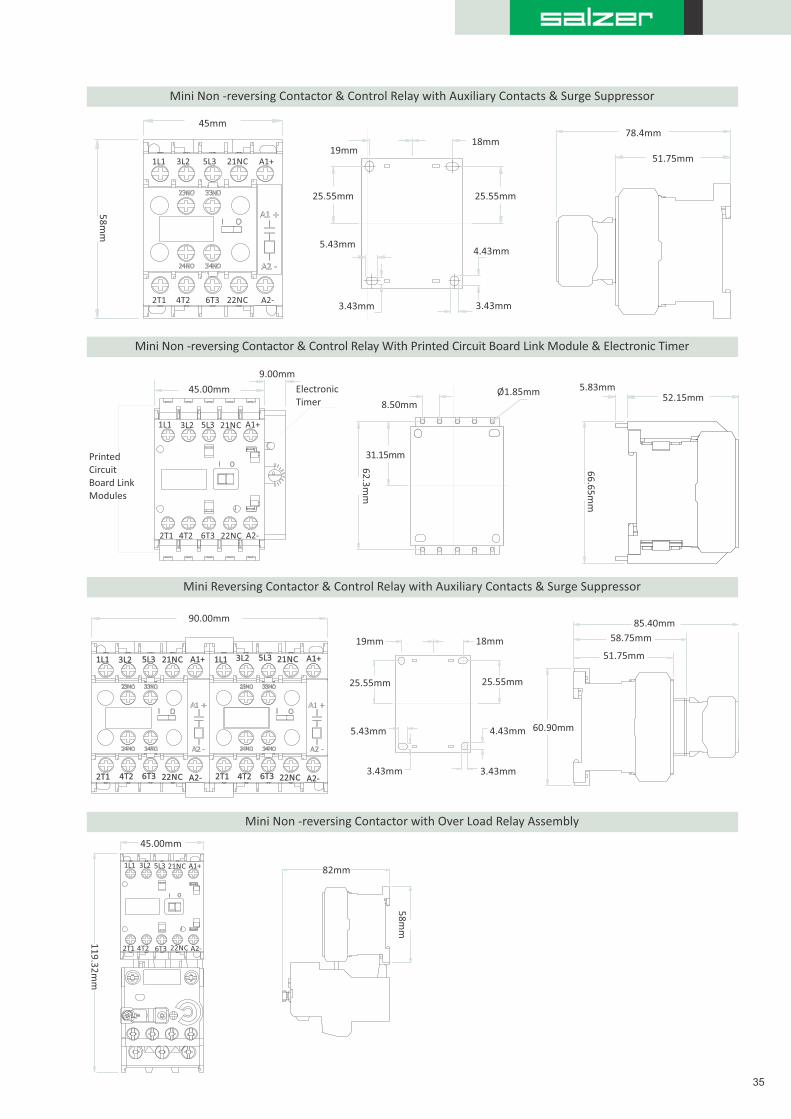
Mini Non -reversing Contactor & Control Relay with Auxiliary Contacts & Surge Suppressor
Mini Non -reversing Contactor & Control Relay With Printed Circuit Board Link Module & Electronic Timer
Mini Reversing Contactor & Control Relay with Auxiliary Contacts & Surge Suppressor
Mini Non -reversing Contactor with Over Load Relay Assembly
36
OVERLOAD RELAY
www.salzergroup.com

Code
BR Bimetallic Overload Relay
Our Series BR Bimetallic Overload Relays are available in five frame sizes for motor full load
currents from 0.28 ~ 112A.
37
Description
Overload Relay Type
Bimetallic Overload Relays
Overload Relay Frame Size and Current Adjustment Range
BR3H40
BR1L40
BR1L63
BR1L80
BR1M12
BR1M18
BR1M28
BR1M40
BR1M63
BR1M80
BR1H10
BR1H12
BR1H15
BR1H17
BR2L40
BR2L63
BR2L80
BR2M12
BR2M18
BR2M28
BR2M40
BR2M63
BR2M80
BR2H10
BR2H12
BR2H15
BR2H17
BR2H23
BR2H32
BR4H57
BR4H63
BR4H70
BR5H80
BR5X11
BR5H97
BR4H50
25 ~ 40
0.28 ~ 0.4
0.4 ~ 0.63
0.56 ~ 0.8
0.8 ~ 1.2
1.2 ~ 1.8
1.8 ~ 2.8
2.8 ~ 4.0
4.0 ~ 6.3
5.6 ~ 8.0
7.0 ~ 10.0
8.0 ~ 12.5
10 ~ 15
11 ~ 17
0.28 ~ 0.4
0.4 ~ 0.63
0.56 ~ 0.8
0.8 ~ 1.2
1.2 ~ 1.8
1.8 ~ 2.8
2.8 ~ 4.0
4.0 ~ 6.3
5.6 ~ 8.0
7.0 ~ 10.0
8 ~ 12.5
10 ~ 15
11 ~ 17
15 ~ 23
22 ~ 32
40 ~ 57
50 ~ 63
57 ~ 70
63 ~ 80
75 ~ 97
90 ~ 112
32 ~ 50
Current Adjustment RangeCode Installs On Contactor
SC032, SC040
MC007, MC009, MC012, MC016
MC007, MC009, MC012, MC016
MC007, MC009, MC012, MC016
MC007, MC009, MC012, MC016
MC007, MC009, MC012, MC016
MC007, MC009, MC012, MC016
MC007, MC009, MC012, MC016
MC007, MC009, MC012, MC016
MC007, MC009, MC012, MC016
MC007, MC009, MC012, MC016
SC009, SC012, SC018, SC025, SC032, SC040
MC007, MC009, MC012, MC016
MC007, MC009, MC012, MC016
SC009, SC012, SC018, SC025, SC032, SC040
SC009, SC012, SC018, SC025, SC032, SC040
SC009, SC012, SC018, SC025, SC032, SC040
SC009, SC012, SC018, SC025, SC032, SC040
SC009, SC012, SC018, SC025, SC032, SC040
SC009, SC012, SC018, SC025, SC032, SC040
SC009, SC012, SC018, SC025, SC032, SC040
SC009, SC012, SC018, SC025, SC032, SC040
SC009, SC012, SC018, SC025, SC032, SC040
SC009, SC012, SC018, SC025, SC032, SC040
SC009, SC012, SC018, SC025, SC032, SC040
SC009, SC012, SC018, SC025, SC032, SC040
SC009, SC012, SC018, SC025, SC032, SC040
SC009, SC012, SC018, SC025, SC032, SC040
SC050, SC065, SC080
SC050, SC065, SC080
SC050, SC065, SC080
SC095, SC105
SC095, SC105
SC095, SC105
SC050, SC065, SC080
MC007, MC009, MC012, MC016

Salzer BR Series Bimetallic Overload Relays provide thermal Trip Class 10 overload
protection for single and three phase motors, and phase loss protection for three
phase motors. Other features like IP20 guarded terminals with dual terminal
markings, integral stop button, and direct mounting will help you to reduce your total
installed costs and enhance the features and performance of your equipment.
5 Frame sizes current rating up to 112 Amps suitable for 9 Standard Contactors & Mini Contactors.
BR1 series Overload Relays for use with MC Series Mini Contactors.
BR1 series Overload Relays include integral connection to auxiliary and coil terminations for ease of wiring during installation
when installed on MC Series Mini Contactors.
BR1 series Overload Relays share the same great features and benefits of the larger frame sizes.
Trip Class 10 for reliable and accurate protection against overload conditions.
Single phase sensitivity to protect motors against damaging phase loss conditions.
Direct mounting to all contactors, including BR1 Overload Relays for use with Series MC Mini Contactors.
IP20 guarded terminals prevent accidental contact with live parts.
Combination head terminal screws allow the use of straight, phillips or posidrive screwdrivers.
Stop button for convenient and economical control circuit wiring.
Ambient temperature compensation ensures reliable motor protection even in high temperature environments.
Salzer BR Series Bimetallic Overload Relays feature a multi-function reset button enabling
the user to select the reset mode-manual or automatic and whether or not to enable the test
function. When the reset button is pressed, with the reset function enabled, the Normally
Open (NO) contact closes and the Normally Closed(NC) contact opens to verify the control
circuit functionality. In addition, the NC contact can be used in a “Stop” circuit. With the test
function disabled, the NO and NC contacts do not change state when the reset button is
pressed-preventing unauthorized personnel from operating the control circuit. Multiple
functions in a single device help you to reduce inventory and customize the overload relay
operation to provide the performance and features you need for your specific application.
Unique Product Feature
Bimetallic Overload Relays
38
A - Automatic Reset OnlyAUTO - Automatic Reset and TestH - Manual Reset Only HAND - Manual Reset and Test
Test button
Trip indicator
Features

Current setting range A 0.28 ~ 17 0.28 ~ 32 25 ~ 40 32 ~ 70 63 ~ 112
Operating Frequency Hz 0 ~ 400
W 0.9 ~ 1.4 1.3 ~ 2.0 1.3 ~ 2.0 1.9 ~ 4.8 3 ~ 4.8Power Dissipation per pole
IEC Ratings
Main Circuits
Rated Insulation Voltage,Ui V 690
Rated Impulse Voltage withstand, Uimp KV 6
Rated Operating Voltage, Ue VAC 690
Maximum Rated Operating Current, Ie A
Maximum fuse size in type “1” gL/gG 90 275A 60 125 200
Maximum fuse size in type “2” gL/gG A 35 63 90 175 250
Control Circuits
Rated Insulation Voltage,Ui V 690
Rated Operating Current, Ie
AC-15
24V 4
48V 3.5
A
60V 3.5
A
110~120V 3.00
A
220~240V 2.00
A
500V 0.50
A400~415V 1.50
A
660~690V 0.30
A
DC-13
1.00
A
A
0.50
0.25
A
0.50
A24V
48V
Short Circuit Coordination
gL/gG 6
A
A
0.10
0.10
A
250V
220V
60V
110V
UL Ratings
Main Circuits
Rated Operating Voltage, Ue
Short Circuit Coordination
Maximum Fuse Size*
High Fault Current
Maximum Fuse Size*
Pilot Duting Rating
Control Circuits
Standard Fault Current
A
kA
A
AC
DC
VAC
C600
R300
A
60 90 90 175 250
30 60 100 15050
5 10
600
A
17 32 40 70 112
Short Circuit Current, Ie A 5kA
*Varies by current settings range of overload relay.
Electrical General
BR1 BR3 BR4 BR5BR2
Technical Specifications
10kA
39
Units

Separate mounting adapters enables Series BR Overload Relays to be installed separately
from a contactor on a 35mm DIN rail or with fixing screws to a panel.
Separate Mounting Adapters
40
Separate Mounting Adapters
Units
BR1 BR3 BR4 BR5BR2
Technical Specifications (Contd.)
Environmental General
Ambient Temperature -25 to +60 C ( -13 to 140 F )
Ambient Storage Temperature -40 to +70 C ( -40 to 158 F )
Construction
3Number of Poles
10Trip Class
Pollution Degree 3
Ingress Protection
Main Circuit Terminals IP20
Control Circuit Terminals IP20
Weight
Kg. 0.15 0.15 0.31 0.31 0.37
lbs. 0.33 0.33 0.68 0.68 0.82
Conductor Size
Main Circuit Terminals
14 ~ 6AWG 14 ~ 6 18 ~ 2 18 ~ 2 8 ~ 1/0UL / CSA
Solid mm2 2.5 ~ 16 1 ~ 35 10 ~ 152.5 ~ 16 1 ~ 35
Stranded mm2 2.5 ~ 16 1 ~ 35 10 ~ 152.5 ~ 16 1 ~ 35
Nm 1.4 ~ 2.3 1.4 ~ 2.3 4 ~ 64 ~ 6 5 ~ 6.5Terminal Torque
Ib.in. 12.4 ~ 20.4 12.4 ~ 20.4 35 ~ 53 35 ~ 53 44.3 ~ 57.5
Control Circuits
UL/CSA AWG 2 X 18 ~ 12
Solid 2 X 1 ~ 4mm2
Stranded mm2 2 X 1 ~ 4
10Ib.in.
*Varies by current settings range of overload relay.
For use with
BR2 Overload Relays
BR5 Overload Relays
BR3 & BR4 Overload Relays
BRSMA2
Code
BRSMA4
BRSMA5
Terminal Torque 1.13 Nm
ROHS Compliance Yes

Bimetallic Overload Relay Trip Characteristics
41
xIe
Ta
3-Phase
2-Phase
2
4
6
10
20
40
601
2
4
6
10
20
40
60
90
120
Min.
Sec.
1
0.6 0.8 1 1.5 2 3 4 5 6 8 10
Circuit Diagrams

Ordering Code
Overload Relay
Ordering Informations
Type
I III IV
Current RangeConfiguration
42
Frame Size
II
BR 2 L 40
BR
I - Type
II - Frame Size
OLR Mounting Adapter
Ordering Informations
BRSMA
I
Relay Frame
II
BRSMA 2I - BRSMA
L40 - 0.28 ~ 0.4
L63 - 0.4 ~ 0.63
L80 - 0.56 ~ 0.8
M12 - 0.8 ~ 1.2
M18 - 1.2 ~ 1.8
M28 - 1.8 ~ 2.8
M40 - 2.8 ~ 4.0
M63 - 4.0 ~ 6.3
M80 - 5.6 ~ 8.0
H10 - 7.0 ~ 10.0
H12 - 8.0 ~ 12.5
H15- 10 ~ 15
H17 - 11 ~ 17
H23 - 15 ~ 23
H32 - 22 ~ 32
H40 - 25 ~ 40
H50 - 32 ~ 50
H57 - 40 ~ 57
H63 - 50 ~ 63
H70 - 57 ~ 70
H80 - 63 ~ 80
H97 - 75 ~ 97
X11 - 90 ~ 112
II - Current Range
1 - 1st Frame
2 - 2nd Frame
3 - 3rd Frame
4 - 5th Frame
Bimetallic Overload
Relay Separate
2 - BR2 Relay Frame
4 - BR3 & BR4 Relay Frame
5 - BR5 Relay Frame
II - Configuration
L - Low Range
M - Medium Range
H - Higher Range
X - Extra Range
II - Relay Frame
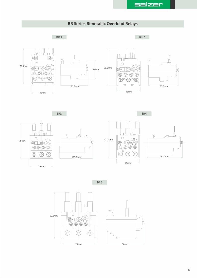
BR Series Bimetallic Overload Relays
43
57mm
83.3mm
70.5mm
45mm
70.5mm
45mm
83.3mm
76.5mm
50mm
105.7mm
81.75mm
50mm
105.7mm
99.2mm
75mm 98mm
BR 1 BR 2
BR3 BR4
BR5

BR Series Separate Mounting Adapters
BRSMA2 Separate Mounting Adapter for use with BR2
BRSMA4 Separate Mounting Adapterfor use with BR3 & BR4
BRSMA5 Separate Mounting Adapterfor use with BR5
44
80mm45mm
70mm 60.35mm
5mm
4.8mm
6.8mm
33.75mm
116.5mm
75mm
98mm
53mm
51.2mm
5.4mm
7.4mm
7.4mm
5.4mm
17.5mm
4.8mm
6.7mm
79mm
50mm

Notes

Salzer Electronics LimitedSamichettipalayam, Jothipuram Post, Coimbatore 641047. INDIA
Tel : +91-422- 4233600 | Fax : +91-422-2692170
e-mail : [email protected]
www.salzergroup.com