contactors - elliott electric
TRANSCRIPT

Low Voltage Products & Systems 1.7ABB Inc. • 888-385-1221 • www.abb.us/lowvoltage 1SXU000023C0202 Rev. A
1
Across the line
Contactors
Across the line contactorsGeneral purpose and motor applications
A-line contactors (9…300)• 3- & 4-pole contactors• General purpose up to 400 A• Motor applications up to 300 hp, 250 kW• NEMA Sizes 00…5• Additional ratings including definite purpose & eleva-
tor duty• AC or DC coil input voltages
B / BC contactors• 3 & 4 pole contactors• Compact solutions up to 5 hp, 5.5 kW• Quick-connect & PCB mount options• AC or DC coil input voltages
EK contactors• 4-pole contactors• AC-1 up to 1000 A• AC or DC coil input voltages
AF series contactors (9…2650)• 3- & 4-pole contactors• General purpose up to 2700 A• Motor applications up to 1150 hp, 900 kW• NEMA Sizes 00…8• DC switching up to 600V• Electronic AC/DC coil input voltages• PLC interface (AF400…AF2650)• Wide variety of accessories• Systems concept coupling units & bus kits• Additional ratings including definite purpose,
elevator duty & capacitive switching
AS / ASL contactors (9…16)• 3-pole contactors• For high-volume applications up to 10 hp• Bulk packaging available• AC or DC coil input voltages
Acr
oss
the
line
Con
tact
ors
3-pole contactors
Standards& approvals
AF09(Z)…AF38(Z)
A/E/L9…A/E/L40
A/E/F50…A/E/F75
A/F95…A/F110
A/F145…AF750,AF1350,AF1650
AF1250,AF2050,AF2650
AS/L09…AS/L16
B/C6…B/C7
RE312527 E312527 E312527 E312527 E36588 E73397 E312527 E191658
LR56745 LR56745 LR16332
Note: B/C6...7 quick-connect and PCB-mount are UL recognized.
4-pole contactors
Standards& approvals
AF09(Z)…AF38(Z)
A/E/L9…A/E/L26
A/E/F45…A/E/F75
EK110…EK550
EK1000B/C6…B/C7
RE319322 E312527 E312527 E36588 – E191658
LR56745 LR56745 – LR15332
Note: B/C6...7 quick-connect and PCB-mount are UL recognized.

1.8 Low Voltage Products & Systems
1SXU000023C0202 Rev. A ABB Inc. • 888-385-1221 • www.abb.us/lowvoltage
1 Across the lin
e
Contactors
AltitudeRefers to the height of the site where the equipment is located, expressed in meters above the sea level.
Ambient temperatureTemperature of the air surrounding the unit.
Circuits• Auxiliary circuit
All the conducting parts of a contactor, intended to be included in a circuit different from the main circuit and the control circuit of the contactor e.g. signalization, interlocking circuits etc …
• Control circuit
All the conducting parts of a contactor (other than the main circuit) included in a circuit used for the closing operation, or opening operation, or both, of the contactor.
• Main circuit
All the conducting parts of a contactor included in the circuit which it is designed to close or open.
Coil operating rangeExpressed as a multiple of the rated control circuit voltage Uc for the lower and upper limits.
Cycle duration Total time of the on-load + off-load period.
Endurance / durability• Electrical endurance
Number of on-load operating cycles (i.e. with current on the main contacts) a contactor can achieve, varies depending on the utilization category.
• Mechanical endurance
Number of off-load operating cycles (i.e. without current on the main contacts) a contactor can achieve.
InchingEnergizing a motor once or repeatedly for short periods to obtain small movements of the driven mechanism.
Insulation class according to the VDE 0110 and NFC 20-040Characterizes contactors suitability in accordance with environment and utilization conditions. A contactor can be classified depending on its own clearance and creepage distances in the insulation classes A, B, C, D which correspond to different insulation voltage values.
The insulation class C is applicable to most of the industrial applications. Equipment described in this catalogue correspond to insulation class C.
Intermittent dutyDuty in which the main contacts of a contactor remain closed for periods of time insufficient to allow the contactor to reach thermal equilibrium, the current-carrying periods being separated by off-load periods of sufficient duration to restore equality of temperature with the cooling medium.
Mounting positionsStated by the manufacturer. Please note restrictions when applicable.
On-load factorRatio of the current flow time to the total time of the cycle x 100.
PluggingStopping or reversing a motor quickly by interchanging two supply leads whilst the motor is running.
Rated breaking capacity; Rated making capacityValue of r.m.s current a contactor can break or make at a fixed voltage value, within the conditions specified by the standards, depending on the utilization category.
General informationTechnical terms and definitions
Rated control circuit voltage UcControl voltage value for which the control circuit of the unit is sized.
Rated insulation voltage UiVoltage value which designates the unit and to which dielectric tests, clearance and creepage distances are referred.
Rated impulse withstand voltage UimpThe highest peak value of an impulse voltage of prescribed form 1.2/50, which does not cause breakdown under specified conditions of test.
Rated operating current IeCurrent value stated by the manufacturer and taking into account the rated operating voltage Ue, the rated frequency, the rated duty, the utilization category, the electrical contact life and the type of the protective enclosure.
Rated operating voltage UeVoltage value to which utilization characteristics of the contactor are referred, i.e. phase to phase voltage in 3 phase circuits.
Conventional thermal current IthValue of current the contactor can withstand with poles in closed position, in free air for an eight hour duty, without the temperature rise of its various parts exceeding the limits specified by the standards.
Resistance to shocksRequirements applicable for instance to vehicles, crane operation or switchgear slide-in module systems.
At the quoted permissible «g» values, contactors must not undergo a change in switching state and O/L relays must not trip.
Resistance to vibrationsRequirements applicable to all the vehicles, vessels and other similar transport systems. At the quoted amplitude and vibration frequency values, the unit must be capable to achieve the required duty.
Short-circuit protection coordinationAchieved by using back-up protection devices such as circuit-breakers, H.R.C. fuses or standard fuses.
Co-ordination types a, b, c are defined in IEC 292-1 publication, VDE 0660, NFC 63-650 standards. Co-ordination types "1" and "2" are defined in IEC 947-4-1.
• Type 1 co-ordination
There has been no discharge of parts beyond the enclosure. Damage to the contactor and the overload relay is acceptable.
• Type 2 co-ordination
No damage to the overload relay or other parts has occurred, except that welding of contactor or starter contacts is permitted, if they are easily separated.
Switching frequencyNumber of operating cycles per hour.
Time• Closing time
Time between energization of the coil until the moment the contacts of the first current path to be closed actually close.
• Opening time
Time from the beginning of state causing breaking until the moment when the contacts of the last current path to be opened are open.
• Minimal operation time
Shortest control duration to ensure complete closing or opening of a contactor.
• Short time current permissible
Value of current which the contactor can withstand in closed position for a short time period and within specified conditions.
• Time constant
Ratio of inductance to the resistance : L/R = mH/Ohm = ms.
Low Voltage Products & Systems 1.9ABB Inc. • 888-385-1221 • www.abb.us/lowvoltage 1SXU000023C0202 Rev. A
1
Across the line
Contactors
General informationIEC Standards, utilization categories
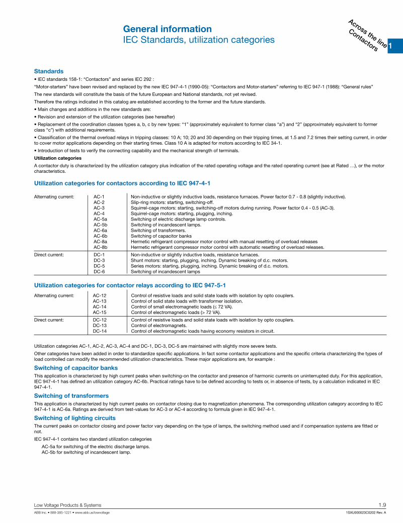
Standards• IEC standards 158-1: “Contactors” and series IEC 292 :
“Motor-starters” have been revised and replaced by the new IEC 947-4-1 (1990-05): “Contactors and Motor-starters” referring to IEC 947-1 (1988): “General rules”
The new standards will constitute the basis of the future European and National standards, not yet revised.
Therefore the ratings indicated in this catalog are established according to the former and the future standards.
• Main changes and additions in the new standards are:
• Revision and extension of the utilization categories (see hereafter)
• Replacement of the coordination classes types a, b, c by new types: “1” (approximately equivalent to former class “a”) and “2” (approximately equivalent to former class “c”) with additional requirements.
• Classification of the thermal overload relays in tripping classes: 10 A; 10; 20 and 30 depending on their tripping times, at 1.5 and 7.2 times their setting current, in order to cover motor applications depending on their starting times. Class 10 A is adapted for motors according to IEC 34-1.
• Introduction of tests to verify the connecting capability and the mechanical strength of terminals.
Utilization categories
A contactor duty is characterized by the utilization category plus indication of the rated operating voltage and the rated operating current (see at Rated …), or the motor characteristics.
Utilization categories for contactors according to IEC 947-4-1
Alternating current: AC-1 Non-inductive or slightly inductive loads, resistance furnaces. Power factor 0.7 - 0.8 (slightly inductive). AC-2 Slip-ring motors: starting, switching-off. AC-3 Squirrel-cage motors: starting, switching-off motors during running. Power factor 0.4 - 0.5 (AC-3). AC-4 Squirrel-cage motors: starting, plugging, inching. AC-5a Switching of electric discharge lamp controls. AC-5b Switching of incandescent lamps. AC-6a Switching of transformers. AC-6b Switching of capacitor banks AC-8a Hermetic refrigerant compressor motor control with manual resetting of overload releases AC-8b Hermetic refrigerant compressor motor control with automatic resetting of overload releases.
Direct current: DC-1 Non-inductive or slightly inductive loads, resistance furnaces. DC-3 Shunt motors: starting, plugging, inching. Dynamic breaking of d.c. motors. DC-5 Series motors: starting, plugging, inching. Dynamic breaking of d.c. motors. DC-6 Switching of incandescent lamps
Alternating current: AC-12 Control of resistive loads and solid state loads with isolation by opto couplers. AC-13 Control of solid state loads with transformer isolation. AC-14 Control of small electromagnetic loads (≤ 72 VA). AC-15 Control of electromagnetic loads (> 72 VA).
Direct current: DC-12 Control of resistive loads and solid state loads with isolation by opto couplers. DC-13 Control of electromagnets. DC-14 Control of electromagnetic loads having economy resistors in circuit.
Utilization categories for contactor relays according to IEC 947-5-1
Utilization categories AC-1, AC-2, AC-3, AC-4 and DC-1, DC-3, DC-5 are maintained with slightly more severe tests.
Other categories have been added in order to standardize specific applications. In fact some contactor applications and the specific criteria characterizing the types of load controlled can modify the recommended utilization characteristics. These major applications are, for example :
Switching of capacitor banksThis application is characterized by high current peaks when switching-on the contactor and presence of harmonic currents on uninterrupted duty. For this application, IEC 947-4-1 has defined an utilization category AC-6b. Practical ratings have to be defined according to tests or, in absence of tests, by a calculation indicated in IEC 947-4-1.
Switching of transformersThis application is characterized by high current peaks on contactor closing due to magnetization phenomena. The corresponding utilization category according to IEC 947-4-1 is AC-6a. Ratings are derived from test-values for AC-3 or AC-4 according to formula given in IEC 947-4-1.
Switching of lighting circuitsThe current peaks on contactor closing and power factor vary depending on the type of lamps, the switching method used and if compensation systems are fitted or not.
IEC 947-4-1 contains two standard utilization categories
AC-5a for switching of the electric discharge lamps. AC-5b for switching of incandescent lamp.

1.10 Low Voltage Products & Systems
1SXU000023C0202 Rev. A ABB Inc. • 888-385-1221 • www.abb.us/lowvoltage
1 Across the lin
e
Contactors General informationMotor ratings
Horsepower to full-load Amperes for AC induction motors
Horse-power (hp)
Full Load Amperes (FLA)
110…120 v ac 200 v ac 208 v ac 220…240 v ac 380…415 v ac 440…480 v ac 550…600 v ac
Single phase
Three phase
Single phase
Three phase
Single phase
Three phase
Single phase
Three phase
Single phase
Three phase
Single phase
Three phase
Single phase
Three phase
1/10 3.0 - - - - - 1.5 - 1.0 - - - - -
1/8 3.8 - - - - - 1.9 - 1.2 - - - - -
1/6 4.4 - 2.5 - 2.4 - 2.2 - 1.4 - - - - -
1/4 5.8 - 3.3 - 3.2 - 2.9 - 1.8 - - - - -
1/3 7.2 - 4.1 - 4.0 - 3.6 - 2.3 - - - - -
1/2 9.8 4.4 5.6 2.5 5.4 2.4 4.9 2.2 3.2 1.3 2.5 1.1 2.0 0.9
3/4 13.8 6.4 7.9 3.7 7.6 3.5 6.9 3.2 4.5 1.8 3.5 1.6 2.8 1.3
1 16.0 8.4 9.2 4.8 8.8 4.6 8.0 4.2 5.1 2.3 4.0 2.1 3.2 1.7
1-1/2 20.0 12.0 11.5 6.9 11.0 6.6 10.0 6.0 6.4 3.3 5.0 3.0 4.0 2.4
2 24.0 13.6 13.8 7.8 13.2 7.5 12.0 6.8 7.7 4.3 6.0 3.4 4.8 2.7
3 34.0 19.2 19.6 11.0 18.7 10.6 17.0 9.6 10.9 6.1 8.5 4.8 6.8 3.9
5 56.0 30.4 32.2 17.5 30.8 16.7 28.0 15.2 17.9 9.7 14.0 7.6 11.2 6.1
7-1/2 80.0 44.0 45.0 25.3 44.0 24.2 40.0 22.0 27.0 14.0 21.0 11.0 16.0 9.0
10 100.0 56.0 57.5 32.2 55.0 30.8 50.0 28.0 33.0 18.0 26.0 14.0 20.0 11.0
15 135.0 84.0 - 48.3 - 46.2 68.0 42.0 44.0 27.0 34.0 21.0 27.0 17.0
20 - 108.0 - 62.1 - 59.4 88.0 54.0 56.0 34.0 44.0 27.0 35.0 22.0
25 - 136.0 - 78.2 - 74.8 110.0 68.0 70.0 44.0 55.0 34.0 44.0 27.0
30 - 160.0 - 92.0 - 88.0 136.0 80.0 87.0 51.0 68.0 40.0 54.0 32.0
40 - 208.0 - 120.0 - 114.0 176.0 104.0 112.0 66.0 88.0 52.0 70.0 41.0
50 - 260.0 - 150.0 - 143.0 216.0 130.0 139.0 83.0 108.0 65.0 86.0 52.0
60 - - - 177.0 - 169.0 - 154.0 - 103.0 - 77.0 - 62.0
75 - - - 221.0 - 211.0 - 192.0 - 128.0 - 96.0 - 77.0
100 - - - 285.0 - 273.0 - 248.0 - 165.0 - 124.0 - 99.0
125 - - - 359.0 - 343.0 - 312.0 - 208.0 - 156.0 - 125.0
150 - - - 414.0 - 396.0 - 360.0 - 240.0 - 180.0 - 144.0
200 - - - 552.0 - 528.0 - 480.0 - 320.0 - 240.0 - 192.0
250 - - - - - - - 604.0 - 403.0 - 302.0 - 242.0
300 - - - - - - - 722.0 - 482.0 - 361.0 - 289.0
350 - - - - - - - 828.0 - 560.0 - 414.0 - 336.0
400 - - - - - - - 954.0 - 636.0 - 477.0 - 382.0
450 - - - - - - - 1030.0 - - 515.0 - 412.0
500 - - - - - - - 1180.0 - 786.0 - 590.0 - 472.0
Full-load motor-running currents in Amperes corresponding to various AC horsepower ratings as published in Table 50.1 of UL 508.

Low Voltage Products & Systems 1.11ABB Inc. • 888-385-1221 • www.abb.us/lowvoltage 1SXU000023C0202 Rev. A
1
Across the line
Contactors
General informationPilot duty ratings and overload trip classes
Pilot duty ratings for AC control circuit contacts
Contact rating
designation
Continuous thermal, test current (A)
Maximum current, 50/60 Hz (A)
120 v ac 240 v ac 480 v ac 600 v ac Volt-amperes
Make Break Make Break Make Break Make Break Make Break
A150 10 60 6.00 - - - - - - 7200 720
A300 10 60 6.00 30 3.00 - - - - 7200 720
A600 10 60 6.00 30 3.00 15 1.50 12 1.20 7200 720
B150 5 30 3.00 - - - - - - 3600 360
B300 5 30 3.00 15 1.50 - - - - 3600 360
B600 5 30 3.00 15 1.50 7.5 0.75 6 0.60 3600 360
C150 2.5 15 1.5 - - - - - - 1800 180
C300 2.5 15 1.5 7.5 0.75 - - - - 1800 180
C600 2.5 15 1.5 7.5 0.75 3.75 0.375 3.00 0.30 1800 180
D150 1.0 3.60 0.60 - - - - - - 432 72
D300 1.0 3.60 0.60 1.80 0.30 - - - - 432 72
E150 0.5 1.80 0.30 - - - - - - 216 36
Mechanical switching ratings and test values as published in Table 1-4-1 of NEMA ICS 5-2000 (R2005, R2010)
Pilot duty ratings for DC control circuit contacts
Contact rating
designation
Continuous thermal, test current (A)
Maximum current, 50/60 Hz (A)
120 v dc 250 v dc 301 to 600 v dc Volt-amperes
Make / Break Make / Break Make / Break Make / Break
N150 10 2.2 - - 275
N300 10 2.2 1.1 - 275
N600 10 2.2 1.1 0.40 275
P150 5.0 1.1 - - 138
P300 5.0 1.1 0.55 - 138
P600 5.0 1.1 0.55 0.20 138
Q150 2.5 0.55 - - 69
Q300 2.5 0.55 0.27 - 69
Q600 2.5 0.55 0.27 0.10 69
R150 1.0 0.22 - - 28
R300 1.0 0.22 0.11 - 28
Mechanical switching ratings and test values as published in Table 1-4-1 of NEMA ICS 5-2000 (R2005, R2010)
Overload trip classesTrip class Tripping time Tp (seconds)
10A 2 < Tp ≤ 10
10 4 < Tp ≤ 10
20 6 < Tp ≤ 20
30 9 < Tp ≤ 30
Trip classes as published in Table 2 of UL 60947-4-1A.
Pilot duty rating explanation
A - 600Max. thermalcurrent
Max. voltage

1.12 Low Voltage Products & Systems
1SXU000023C0202 Rev. A ABB Inc. • 888-385-1221 • www.abb.us/lowvoltage
1 Across the lin
e
Contactors General informationAF Series contactorsAF09 - AF110
ApplicationAF series contactors (9...110) are primarily used for controlling single and three phase motors and switching power circuits up to 600V AC, 240V DC
DescriptionAF series contactors are provided in either three or four power pole configurations with a variety of accessories including auxiliary contacts, close coupling adaptors, interlocks, and busbars.
Control circuit typesAF series contactor coils are designed to utilize both AC (50/60 Hz) and DC control circuit inputs ranging from 12…500V. Surge suppression is included.
Contactor types3 NO pole: AF09…AF1104 NO pole: AF09…AF752 NO / 2 NC pole: AF09…AF75
Mounting hole pattern identical from AF09…AF38. Only three different patterns for contactors AF09…AF110
Quick DIN-rail mount & dismount (no tools required AF09…AF38)• 35 x 7.5mm for AF09…AF38• 35 x 15mm for AF09…AF75• 75mm for AF45…AF110
Integral surge suppression AF09…AF110
Actuator for side-mount accessories
Mechanical interlocks with no additional width for AF09…AF38
Contoured sides for easy access to panel mounting holes
Terminals on AF09…AF110 contactors are deliv-ered in open position with captive screws (screws of unused terminals must be tightened)
IP20 degree protection according to IEC/EN 60947-1; protection from live parts according to VDE0106 Part. 100.
Detachable coil terminals (AF09…AF38)• Can be pre-wired prior to installation• Can easily be rotated from top (standard)
to bottom
Front-mount coil termination available
Stops for attaching front-mount accessories
Function markers included as standard on AF09...AF38; available as accessory AF50…AF110
Clear indication of coil voltages and frequen-cies
Terminal screws:• Posidrive (+,-) No 2 AF09…AF75• M8 hex threaded socket screw for
AF95…AF110
Catalog number explanationFor reference only – not all combinations will produce
valid catalog numbers
AF09 - 30 -10 - 13Contactor series & frame size
Power pole configuration • 30 = 3 NO • 40 = 4 NO • 22 = 2 NO / 2 NC
Coil voltage code (see product selection pages)
Auxiliary pole configuration • 00 - No auxiliary provided • 10 = 1 NO • 01 = 1 NC • 11 = 1 NO / 1 NC • 22 = 2 NO / 2 NC

1.14 Low Voltage Products & Systems
1SXU000023C0202 Rev. A ABB Inc. • 888-385-1221 • www.abb.us/lowvoltage
1 Across the lin
e
Contactors AF non-reversing, 3-poleFor applications up to 1150 hp, 900 kWElectronic AC/DC operated coils
Electrical ratings 1 Non-reversing Electrical ratings 12 Mechanically interlocked ReversingIEC/EN 60947-4-1
UL 508, 60947-4-1ACSA C22.2 No.14, 60947-4-1-07 Standard
auxiliary contacts
3Catalog number
UL 508, 60947-4-1ACSA C22.2 No.14, 60947-4-1-07 Standard
auxiliary contacts
Catalognumber
3
Standardauxiliary contacts
Catalognumber
3
Rated operational cur-rent Ie, AC-1, AC-3 (A)
Rated operational power Pe, AC-3, 55°C (kW) 2
AC general purpose
ratings (A)
Maximummotor
switchingcurrent
(A)
AC motor ratings, breaking all lines, three phase, 50/60 Hz (hp)
AC generalpurpose
ratings (A)
Maximummotor
switchingcurrent
(A)
AC motor ratings, breaking all lines,three phase, 50/60 Hz (hp)
AC-1 40°C
AC-355°C 2
220… 240V
380... 400V
690V 600V200...208V
220...240V
440…480V
550…600V
NO NC 600V200...208V
220...240V
440...480V
550...600V
NO NC NO NC
25 9 2.2 4 5.5 25 9 2 2 5 7.51 - AF09-30-10-Δ 25 9 2 2 5 7.5 2 2 AF09M-30-22-Δ 2 2 AF09R-30-22-Δ- 1 AF09-30-01-Δ - - - - - - - - - - - -
28 12 3 5.5 7.5 28 11 3 3 7.5 101 - AF12-30-10-Δ 28 11 3 3 7.5 10 2 2 AF12M-30-22-Δ 2 2 AF12R-30-22-Δ- 1 AF12-30-01-Δ - - - - - - - - - - - -
30 18 4 7.5 9 30 17 5 5 10 151 - AF16-30-10-Δ 30 17 5 5 10 15 2 2 AF16M-30-22-Δ 2 2 AF16R-30-22-Δ- 1 AF16-30-01-Δ - - - - - - - - - - - -
45 26 6.5 11 15 45 24.2 7.5 7.5 15 20 - - AF26-30-00-Δ 45 24.2 7.5 7.5 15 20 - 2 AF26M-30-02-Δ - 2 AF26R-30-02-Δ50 32 9 15 18.5 50 30.8 10 10 20 25 - - AF30-30-00-Δ 50 30.8 10 10 20 25 - 2 AF30M-30-02-Δ - 2 AF30R-30-02-Δ50 38 11 18.5 22 50 - - - - - - - AF38-30-00-Δ - - - - - - - - - - - -100 50 15 22 30 80 54 15 20 40 50 1 1 AF50-30-11-Δ 80 54 15 20 40 50 2 2 AF50M-30-11-Δ 2 2 AF50R-30-11-Δ115 65 18.5 30 37 90 68 20 25 50 60 1 1 AF63-30-11-Δ 90 68 20 25 50 60 2 2 AF63M-30-11-Δ 2 2 AF63R-30-11-Δ125 75 22 37 40 105 80 25 30 60 75 1 1 AF75-30-11-Δ 105 80 25 30 60 75 2 2 AF75M-30-11-Δ 2 2 AF75R-30-11-Δ145 96 25 45 55 150 88 30 30 60 75 1 1 AF95-30-11-Δ 150 88 30 30 60 75 2 2 AF95M-30-11-Δ 2 2 AF95R-30-11-Δ160 110 30 55 75 150 104 30 40 75 100 1 1 AF110-30-11-Δ 150 104 30 40 75 100 2 2 AF110M-30-11-Δ 2 2 AF110R-30-11-Δ250 145 45 75 110 230 130 40 50 100 125 1 1 AF145-30-11-Δ 230 130 40 50 100 125 2 2 AF145M-30-11-Δ 2 2 AF145R-30-11-Δ275 185 55 90 132 250 156 50 60 125 150 1 1 AF185-30-11-Δ 250 156 50 60 125 150 2 2 AF185M-30-11-Δ 2 2 AF185R-30-11-Δ350 210 59 110 160 300 192 60 75 150 200 1 1 AF210-30-11-Δ 300 192 60 75 150 200 2 2 AF210M-30-11-Δ 2 2 AF210R-30-11-Δ400 260 80 140 200 350 248 75 100 200 250 1 1 AF260-30-11-Δ 350 248 75 100 200 250 2 2 AF260M-30-11-Δ 2 2 AF260R-30-11-Δ500 305 90 160 250 400 302 100 100 250 300 1 1 AF300-30-11-Δ 400 302 100 100 250 300 2 2 AF300M-30-11-Δ 2 2 AF300R-30-11-Δ600 400 110 200 315 550 414 125 150 350 400 1 1 AF400-30-11-Δ 550 414 125 150 350 400 2 2 AF400M-30-11-Δ 2 2 AF400R-30-11-Δ700 460 132 250 355 650 480 150 200 400 500 1 1 AF460-30-11-Δ 650 480 150 200 400 500 2 2 AF460M-30-11-Δ 2 2 AF460R-30-11-Δ800 580 160 315 500 750 604 250 250 500 600 1 1 AF580-30-11-Δ 750 604 250 250 500 600 2 2 AF580M-30-11-Δ 2 2 AF580R-30-11-Δ1050 750 220 400 600 900 722 250 300 600 700 1 1 AF750-30-11-Δ 900 722 250 300 600 700 2 2 AF750M-30-11-Δ 2 2 AF750R-30-11-Δ1260 - - - - 1210 - - - - - 1 1 AF1250-30-11-Δ - - - - - - - - - - - -1350 860 257 475 750 1350 954 - 400 800 1000 1 1 AF1350-30-11-Δ - - - - - - - - - - - -1650 1050 315 560 900 1650 1050 - 450 900 1150 1 1 AF1650-30-11-Δ - - - - - - - - - - - -2050 - - - - 2100 - - - - - 1 1 AF2050-30-11-Δ - - - - - - - - - - - -2650 - - - - 2700 - - - - - 1 1 AF2650-30-11-Δ - - - - - - - - - - - -
Coil voltage selection chart (Δ)Rated control circuit
voltage Uc 4AF09…AF38
AF50…AF300
AF400…AF750
AF1250AF1350…AF2650
20...60V DC 11 72 - - -
24...60V AC 11 - - - -
24...60V DC - - 68 68 -
48...130V AC/DC 12 69 69 69 -
100...250V AC/DC 13 70 70 70 70
250...500V AC/DC 14 - 71 - -Example(s):24V DC input voltage: AF16-30-10-11120V AC input voltage: AF300-30-11-70
1 For selection purposes; for complete electrical ratings, see Technical Data.2 AF09... AF38 at 60°C.3 Auxiliary contacts integral for AF09…AF16; all others side-mount.4 AC coil input voltage(s) at 50/60 Hz unless specified.
Control inputsAF400...AF2650 are equipped with integral low voltage inputs, allowing for direct PLC control:
AF09…AF16 AF95…AF110 AF210…AF300 AF1350…AF2650 AF09R…AF16R AF95R…AF110R
R

Low Voltage Products & Systems 1.7ABB Inc. • 888-385-1221 • www.abb.us/lowvoltage 1SXU000023C0202 Rev. A
1
Across the line
Contactors
Across the line contactorsGeneral purpose and motor applications
A-line contactors (9…300)• 3- & 4-pole contactors• General purpose up to 400 A• Motor applications up to 300 hp, 250 kW• NEMA Sizes 00…5• Additional ratings including definite purpose & eleva-
tor duty• AC or DC coil input voltages
B / BC contactors• 3 & 4 pole contactors• Compact solutions up to 5 hp, 5.5 kW• Quick-connect & PCB mount options• AC or DC coil input voltages
EK contactors• 4-pole contactors• AC-1 up to 1000 A• AC or DC coil input voltages
AF series contactors (9…2650)• 3- & 4-pole contactors• General purpose up to 2700 A• Motor applications up to 1150 hp, 900 kW• NEMA Sizes 00…8• DC switching up to 600V• Electronic AC/DC coil input voltages• PLC interface (AF400…AF2650)• Wide variety of accessories• Systems concept coupling units & bus kits• Additional ratings including definite purpose,
elevator duty & capacitive switching
AS / ASL contactors (9…16)• 3-pole contactors• For high-volume applications up to 10 hp• Bulk packaging available• AC or DC coil input voltages
Acr
oss
the
line
Con
tact
ors
3-pole contactors
Standards& approvals
AF09(Z)…AF38(Z)
A/E/L9…A/E/L40
A/E/F50…A/E/F75
A/F95…A/F110
A/F145…AF750,AF1350,AF1650
AF1250,AF2050,AF2650
AS/L09…AS/L16
B/C6…B/C7
RE312527 E312527 E312527 E312527 E36588 E73397 E312527 E191658
LR56745 LR56745 LR16332
Note: B/C6...7 quick-connect and PCB-mount are UL recognized.
4-pole contactors
Standards& approvals
AF09(Z)…AF38(Z)
A/E/L9…A/E/L26
A/E/F45…A/E/F75
EK110…EK550
EK1000B/C6…B/C7
RE319322 E312527 E312527 E36588 – E191658
LR56745 LR56745 – LR15332
Note: B/C6...7 quick-connect and PCB-mount are UL recognized.

1.8 Low Voltage Products & Systems
1SXU000023C0202 Rev. A ABB Inc. • 888-385-1221 • www.abb.us/lowvoltage
1 Across the lin
e
Contactors
AltitudeRefers to the height of the site where the equipment is located, expressed in meters above the sea level.
Ambient temperatureTemperature of the air surrounding the unit.
Circuits• Auxiliary circuit
All the conducting parts of a contactor, intended to be included in a circuit different from the main circuit and the control circuit of the contactor e.g. signalization, interlocking circuits etc …
• Control circuit
All the conducting parts of a contactor (other than the main circuit) included in a circuit used for the closing operation, or opening operation, or both, of the contactor.
• Main circuit
All the conducting parts of a contactor included in the circuit which it is designed to close or open.
Coil operating rangeExpressed as a multiple of the rated control circuit voltage Uc for the lower and upper limits.
Cycle duration Total time of the on-load + off-load period.
Endurance / durability• Electrical endurance
Number of on-load operating cycles (i.e. with current on the main contacts) a contactor can achieve, varies depending on the utilization category.
• Mechanical endurance
Number of off-load operating cycles (i.e. without current on the main contacts) a contactor can achieve.
InchingEnergizing a motor once or repeatedly for short periods to obtain small movements of the driven mechanism.
Insulation class according to the VDE 0110 and NFC 20-040Characterizes contactors suitability in accordance with environment and utilization conditions. A contactor can be classified depending on its own clearance and creepage distances in the insulation classes A, B, C, D which correspond to different insulation voltage values.
The insulation class C is applicable to most of the industrial applications. Equipment described in this catalogue correspond to insulation class C.
Intermittent dutyDuty in which the main contacts of a contactor remain closed for periods of time insufficient to allow the contactor to reach thermal equilibrium, the current-carrying periods being separated by off-load periods of sufficient duration to restore equality of temperature with the cooling medium.
Mounting positionsStated by the manufacturer. Please note restrictions when applicable.
On-load factorRatio of the current flow time to the total time of the cycle x 100.
PluggingStopping or reversing a motor quickly by interchanging two supply leads whilst the motor is running.
Rated breaking capacity; Rated making capacityValue of r.m.s current a contactor can break or make at a fixed voltage value, within the conditions specified by the standards, depending on the utilization category.
General informationTechnical terms and definitions
Rated control circuit voltage UcControl voltage value for which the control circuit of the unit is sized.
Rated insulation voltage UiVoltage value which designates the unit and to which dielectric tests, clearance and creepage distances are referred.
Rated impulse withstand voltage UimpThe highest peak value of an impulse voltage of prescribed form 1.2/50, which does not cause breakdown under specified conditions of test.
Rated operating current IeCurrent value stated by the manufacturer and taking into account the rated operating voltage Ue, the rated frequency, the rated duty, the utilization category, the electrical contact life and the type of the protective enclosure.
Rated operating voltage UeVoltage value to which utilization characteristics of the contactor are referred, i.e. phase to phase voltage in 3 phase circuits.
Conventional thermal current IthValue of current the contactor can withstand with poles in closed position, in free air for an eight hour duty, without the temperature rise of its various parts exceeding the limits specified by the standards.
Resistance to shocksRequirements applicable for instance to vehicles, crane operation or switchgear slide-in module systems.
At the quoted permissible «g» values, contactors must not undergo a change in switching state and O/L relays must not trip.
Resistance to vibrationsRequirements applicable to all the vehicles, vessels and other similar transport systems. At the quoted amplitude and vibration frequency values, the unit must be capable to achieve the required duty.
Short-circuit protection coordinationAchieved by using back-up protection devices such as circuit-breakers, H.R.C. fuses or standard fuses.
Co-ordination types a, b, c are defined in IEC 292-1 publication, VDE 0660, NFC 63-650 standards. Co-ordination types "1" and "2" are defined in IEC 947-4-1.
• Type 1 co-ordination
There has been no discharge of parts beyond the enclosure. Damage to the contactor and the overload relay is acceptable.
• Type 2 co-ordination
No damage to the overload relay or other parts has occurred, except that welding of contactor or starter contacts is permitted, if they are easily separated.
Switching frequencyNumber of operating cycles per hour.
Time• Closing time
Time between energization of the coil until the moment the contacts of the first current path to be closed actually close.
• Opening time
Time from the beginning of state causing breaking until the moment when the contacts of the last current path to be opened are open.
• Minimal operation time
Shortest control duration to ensure complete closing or opening of a contactor.
• Short time current permissible
Value of current which the contactor can withstand in closed position for a short time period and within specified conditions.
• Time constant
Ratio of inductance to the resistance : L/R = mH/Ohm = ms.

Low Voltage Products & Systems 1.9ABB Inc. • 888-385-1221 • www.abb.us/lowvoltage 1SXU000023C0202 Rev. A
1
Across the line
Contactors
General informationIEC Standards, utilization categories
Standards• IEC standards 158-1: “Contactors” and series IEC 292 :
“Motor-starters” have been revised and replaced by the new IEC 947-4-1 (1990-05): “Contactors and Motor-starters” referring to IEC 947-1 (1988): “General rules”
The new standards will constitute the basis of the future European and National standards, not yet revised.
Therefore the ratings indicated in this catalog are established according to the former and the future standards.
• Main changes and additions in the new standards are:
• Revision and extension of the utilization categories (see hereafter)
• Replacement of the coordination classes types a, b, c by new types: “1” (approximately equivalent to former class “a”) and “2” (approximately equivalent to former class “c”) with additional requirements.
• Classification of the thermal overload relays in tripping classes: 10 A; 10; 20 and 30 depending on their tripping times, at 1.5 and 7.2 times their setting current, in order to cover motor applications depending on their starting times. Class 10 A is adapted for motors according to IEC 34-1.
• Introduction of tests to verify the connecting capability and the mechanical strength of terminals.
Utilization categories
A contactor duty is characterized by the utilization category plus indication of the rated operating voltage and the rated operating current (see at Rated …), or the motor characteristics.
Utilization categories for contactors according to IEC 947-4-1
Alternating current: AC-1 Non-inductive or slightly inductive loads, resistance furnaces. Power factor 0.7 - 0.8 (slightly inductive). AC-2 Slip-ring motors: starting, switching-off. AC-3 Squirrel-cage motors: starting, switching-off motors during running. Power factor 0.4 - 0.5 (AC-3). AC-4 Squirrel-cage motors: starting, plugging, inching. AC-5a Switching of electric discharge lamp controls. AC-5b Switching of incandescent lamps. AC-6a Switching of transformers. AC-6b Switching of capacitor banks AC-8a Hermetic refrigerant compressor motor control with manual resetting of overload releases AC-8b Hermetic refrigerant compressor motor control with automatic resetting of overload releases.
Direct current: DC-1 Non-inductive or slightly inductive loads, resistance furnaces. DC-3 Shunt motors: starting, plugging, inching. Dynamic breaking of d.c. motors. DC-5 Series motors: starting, plugging, inching. Dynamic breaking of d.c. motors. DC-6 Switching of incandescent lamps
Alternating current: AC-12 Control of resistive loads and solid state loads with isolation by opto couplers. AC-13 Control of solid state loads with transformer isolation. AC-14 Control of small electromagnetic loads (≤ 72 VA). AC-15 Control of electromagnetic loads (> 72 VA).
Direct current: DC-12 Control of resistive loads and solid state loads with isolation by opto couplers. DC-13 Control of electromagnets. DC-14 Control of electromagnetic loads having economy resistors in circuit.
Utilization categories for contactor relays according to IEC 947-5-1
Utilization categories AC-1, AC-2, AC-3, AC-4 and DC-1, DC-3, DC-5 are maintained with slightly more severe tests.
Other categories have been added in order to standardize specific applications. In fact some contactor applications and the specific criteria characterizing the types of load controlled can modify the recommended utilization characteristics. These major applications are, for example :
Switching of capacitor banksThis application is characterized by high current peaks when switching-on the contactor and presence of harmonic currents on uninterrupted duty. For this application, IEC 947-4-1 has defined an utilization category AC-6b. Practical ratings have to be defined according to tests or, in absence of tests, by a calculation indicated in IEC 947-4-1.
Switching of transformersThis application is characterized by high current peaks on contactor closing due to magnetization phenomena. The corresponding utilization category according to IEC 947-4-1 is AC-6a. Ratings are derived from test-values for AC-3 or AC-4 according to formula given in IEC 947-4-1.
Switching of lighting circuitsThe current peaks on contactor closing and power factor vary depending on the type of lamps, the switching method used and if compensation systems are fitted or not.
IEC 947-4-1 contains two standard utilization categories
AC-5a for switching of the electric discharge lamps. AC-5b for switching of incandescent lamp.

1.10 Low Voltage Products & Systems
1SXU000023C0202 Rev. A ABB Inc. • 888-385-1221 • www.abb.us/lowvoltage
1 Across the lin
e
Contactors General informationMotor ratings
Horsepower to full-load Amperes for AC induction motors
Horse-power (hp)
Full Load Amperes (FLA)
110…120 v ac 200 v ac 208 v ac 220…240 v ac 380…415 v ac 440…480 v ac 550…600 v ac
Single phase
Three phase
Single phase
Three phase
Single phase
Three phase
Single phase
Three phase
Single phase
Three phase
Single phase
Three phase
Single phase
Three phase
1/10 3.0 - - - - - 1.5 - 1.0 - - - - -
1/8 3.8 - - - - - 1.9 - 1.2 - - - - -
1/6 4.4 - 2.5 - 2.4 - 2.2 - 1.4 - - - - -
1/4 5.8 - 3.3 - 3.2 - 2.9 - 1.8 - - - - -
1/3 7.2 - 4.1 - 4.0 - 3.6 - 2.3 - - - - -
1/2 9.8 4.4 5.6 2.5 5.4 2.4 4.9 2.2 3.2 1.3 2.5 1.1 2.0 0.9
3/4 13.8 6.4 7.9 3.7 7.6 3.5 6.9 3.2 4.5 1.8 3.5 1.6 2.8 1.3
1 16.0 8.4 9.2 4.8 8.8 4.6 8.0 4.2 5.1 2.3 4.0 2.1 3.2 1.7
1-1/2 20.0 12.0 11.5 6.9 11.0 6.6 10.0 6.0 6.4 3.3 5.0 3.0 4.0 2.4
2 24.0 13.6 13.8 7.8 13.2 7.5 12.0 6.8 7.7 4.3 6.0 3.4 4.8 2.7
3 34.0 19.2 19.6 11.0 18.7 10.6 17.0 9.6 10.9 6.1 8.5 4.8 6.8 3.9
5 56.0 30.4 32.2 17.5 30.8 16.7 28.0 15.2 17.9 9.7 14.0 7.6 11.2 6.1
7-1/2 80.0 44.0 45.0 25.3 44.0 24.2 40.0 22.0 27.0 14.0 21.0 11.0 16.0 9.0
10 100.0 56.0 57.5 32.2 55.0 30.8 50.0 28.0 33.0 18.0 26.0 14.0 20.0 11.0
15 135.0 84.0 - 48.3 - 46.2 68.0 42.0 44.0 27.0 34.0 21.0 27.0 17.0
20 - 108.0 - 62.1 - 59.4 88.0 54.0 56.0 34.0 44.0 27.0 35.0 22.0
25 - 136.0 - 78.2 - 74.8 110.0 68.0 70.0 44.0 55.0 34.0 44.0 27.0
30 - 160.0 - 92.0 - 88.0 136.0 80.0 87.0 51.0 68.0 40.0 54.0 32.0
40 - 208.0 - 120.0 - 114.0 176.0 104.0 112.0 66.0 88.0 52.0 70.0 41.0
50 - 260.0 - 150.0 - 143.0 216.0 130.0 139.0 83.0 108.0 65.0 86.0 52.0
60 - - - 177.0 - 169.0 - 154.0 - 103.0 - 77.0 - 62.0
75 - - - 221.0 - 211.0 - 192.0 - 128.0 - 96.0 - 77.0
100 - - - 285.0 - 273.0 - 248.0 - 165.0 - 124.0 - 99.0
125 - - - 359.0 - 343.0 - 312.0 - 208.0 - 156.0 - 125.0
150 - - - 414.0 - 396.0 - 360.0 - 240.0 - 180.0 - 144.0
200 - - - 552.0 - 528.0 - 480.0 - 320.0 - 240.0 - 192.0
250 - - - - - - - 604.0 - 403.0 - 302.0 - 242.0
300 - - - - - - - 722.0 - 482.0 - 361.0 - 289.0
350 - - - - - - - 828.0 - 560.0 - 414.0 - 336.0
400 - - - - - - - 954.0 - 636.0 - 477.0 - 382.0
450 - - - - - - - 1030.0 - - 515.0 - 412.0
500 - - - - - - - 1180.0 - 786.0 - 590.0 - 472.0
Full-load motor-running currents in Amperes corresponding to various AC horsepower ratings as published in Table 50.1 of UL 508.

Low Voltage Products & Systems 1.11ABB Inc. • 888-385-1221 • www.abb.us/lowvoltage 1SXU000023C0202 Rev. A
1
Across the line
Contactors
General informationPilot duty ratings and overload trip classes
Pilot duty ratings for AC control circuit contacts
Contact rating
designation
Continuous thermal, test current (A)
Maximum current, 50/60 Hz (A)
120 v ac 240 v ac 480 v ac 600 v ac Volt-amperes
Make Break Make Break Make Break Make Break Make Break
A150 10 60 6.00 - - - - - - 7200 720
A300 10 60 6.00 30 3.00 - - - - 7200 720
A600 10 60 6.00 30 3.00 15 1.50 12 1.20 7200 720
B150 5 30 3.00 - - - - - - 3600 360
B300 5 30 3.00 15 1.50 - - - - 3600 360
B600 5 30 3.00 15 1.50 7.5 0.75 6 0.60 3600 360
C150 2.5 15 1.5 - - - - - - 1800 180
C300 2.5 15 1.5 7.5 0.75 - - - - 1800 180
C600 2.5 15 1.5 7.5 0.75 3.75 0.375 3.00 0.30 1800 180
D150 1.0 3.60 0.60 - - - - - - 432 72
D300 1.0 3.60 0.60 1.80 0.30 - - - - 432 72
E150 0.5 1.80 0.30 - - - - - - 216 36
Mechanical switching ratings and test values as published in Table 1-4-1 of NEMA ICS 5-2000 (R2005, R2010)
Pilot duty ratings for DC control circuit contacts
Contact rating
designation
Continuous thermal, test current (A)
Maximum current, 50/60 Hz (A)
120 v dc 250 v dc 301 to 600 v dc Volt-amperes
Make / Break Make / Break Make / Break Make / Break
N150 10 2.2 - - 275
N300 10 2.2 1.1 - 275
N600 10 2.2 1.1 0.40 275
P150 5.0 1.1 - - 138
P300 5.0 1.1 0.55 - 138
P600 5.0 1.1 0.55 0.20 138
Q150 2.5 0.55 - - 69
Q300 2.5 0.55 0.27 - 69
Q600 2.5 0.55 0.27 0.10 69
R150 1.0 0.22 - - 28
R300 1.0 0.22 0.11 - 28
Mechanical switching ratings and test values as published in Table 1-4-1 of NEMA ICS 5-2000 (R2005, R2010)
Overload trip classesTrip class Tripping time Tp (seconds)
10A 2 < Tp ≤ 10
10 4 < Tp ≤ 10
20 6 < Tp ≤ 20
30 9 < Tp ≤ 30
Trip classes as published in Table 2 of UL 60947-4-1A.
Pilot duty rating explanation
A - 600Max. thermalcurrent
Max. voltage

1.12 Low Voltage Products & Systems
1SXU000023C0202 Rev. A ABB Inc. • 888-385-1221 • www.abb.us/lowvoltage
1 Across the lin
e
Contactors General informationAF Series contactorsAF09 - AF110
ApplicationAF series contactors (9...110) are primarily used for controlling single and three phase motors and switching power circuits up to 600V AC, 240V DC
DescriptionAF series contactors are provided in either three or four power pole configurations with a variety of accessories including auxiliary contacts, close coupling adaptors, interlocks, and busbars.
Control circuit typesAF series contactor coils are designed to utilize both AC (50/60 Hz) and DC control circuit inputs ranging from 12…500V. Surge suppression is included.
Contactor types3 NO pole: AF09…AF1104 NO pole: AF09…AF752 NO / 2 NC pole: AF09…AF75
Mounting hole pattern identical from AF09…AF38. Only three different patterns for contactors AF09…AF110
Quick DIN-rail mount & dismount (no tools required AF09…AF38)• 35 x 7.5mm for AF09…AF38• 35 x 15mm for AF09…AF75• 75mm for AF45…AF110
Integral surge suppression AF09…AF110
Actuator for side-mount accessories
Mechanical interlocks with no additional width for AF09…AF38
Contoured sides for easy access to panel mounting holes
Terminals on AF09…AF110 contactors are deliv-ered in open position with captive screws (screws of unused terminals must be tightened)
IP20 degree protection according to IEC/EN 60947-1; protection from live parts according to VDE0106 Part. 100.
Detachable coil terminals (AF09…AF38)• Can be pre-wired prior to installation• Can easily be rotated from top (standard)
to bottom
Front-mount coil termination available
Stops for attaching front-mount accessories
Function markers included as standard on AF09...AF38; available as accessory AF50…AF110
Clear indication of coil voltages and frequen-cies
Terminal screws:• Posidrive (+,-) No 2 AF09…AF75• M8 hex threaded socket screw for
AF95…AF110
Catalog number explanationFor reference only – not all combinations will produce
valid catalog numbers
AF09 - 30 -10 - 13Contactor series & frame size
Power pole configuration • 30 = 3 NO • 40 = 4 NO • 22 = 2 NO / 2 NC
Coil voltage code (see product selection pages)
Auxiliary pole configuration • 00 - No auxiliary provided • 10 = 1 NO • 01 = 1 NC • 11 = 1 NO / 1 NC • 22 = 2 NO / 2 NC

1.14 Low Voltage Products & Systems
1SXU000023C0202 Rev. A ABB Inc. • 888-385-1221 • www.abb.us/lowvoltage
1 Across the lin
e
Contactors AF non-reversing, 3-poleFor applications up to 1150 hp, 900 kWElectronic AC/DC operated coils
Electrical ratings 1 Non-reversing Electrical ratings 12 Mechanically interlocked ReversingIEC/EN 60947-4-1
UL 508, 60947-4-1ACSA C22.2 No.14, 60947-4-1-07 Standard
auxiliary contacts
3Catalog number
UL 508, 60947-4-1ACSA C22.2 No.14, 60947-4-1-07 Standard
auxiliary contacts
Catalognumber
3
Standardauxiliary contacts
Catalognumber
3
Rated operational cur-rent Ie, AC-1, AC-3 (A)
Rated operational power Pe, AC-3, 55°C (kW) 2
AC general purpose
ratings (A)
Maximummotor
switchingcurrent
(A)
AC motor ratings, breaking all lines, three phase, 50/60 Hz (hp)
AC generalpurpose
ratings (A)
Maximummotor
switchingcurrent
(A)
AC motor ratings, breaking all lines,three phase, 50/60 Hz (hp)
AC-1 40°C
AC-355°C 2
220… 240V
380... 400V
690V 600V200...208V
220...240V
440…480V
550…600V
NO NC 600V200...208V
220...240V
440...480V
550...600V
NO NC NO NC
25 9 2.2 4 5.5 25 9 2 2 5 7.51 - AF09-30-10-Δ 25 9 2 2 5 7.5 2 2 AF09M-30-22-Δ 2 2 AF09R-30-22-Δ- 1 AF09-30-01-Δ - - - - - - - - - - - -
28 12 3 5.5 7.5 28 11 3 3 7.5 101 - AF12-30-10-Δ 28 11 3 3 7.5 10 2 2 AF12M-30-22-Δ 2 2 AF12R-30-22-Δ- 1 AF12-30-01-Δ - - - - - - - - - - - -
30 18 4 7.5 9 30 17 5 5 10 151 - AF16-30-10-Δ 30 17 5 5 10 15 2 2 AF16M-30-22-Δ 2 2 AF16R-30-22-Δ- 1 AF16-30-01-Δ - - - - - - - - - - - -
45 26 6.5 11 15 45 24.2 7.5 7.5 15 20 - - AF26-30-00-Δ 45 24.2 7.5 7.5 15 20 - 2 AF26M-30-02-Δ - 2 AF26R-30-02-Δ50 32 9 15 18.5 50 30.8 10 10 20 25 - - AF30-30-00-Δ 50 30.8 10 10 20 25 - 2 AF30M-30-02-Δ - 2 AF30R-30-02-Δ50 38 11 18.5 22 50 - - - - - - - AF38-30-00-Δ - - - - - - - - - - - -100 50 15 22 30 80 54 15 20 40 50 1 1 AF50-30-11-Δ 80 54 15 20 40 50 2 2 AF50M-30-11-Δ 2 2 AF50R-30-11-Δ115 65 18.5 30 37 90 68 20 25 50 60 1 1 AF63-30-11-Δ 90 68 20 25 50 60 2 2 AF63M-30-11-Δ 2 2 AF63R-30-11-Δ125 75 22 37 40 105 80 25 30 60 75 1 1 AF75-30-11-Δ 105 80 25 30 60 75 2 2 AF75M-30-11-Δ 2 2 AF75R-30-11-Δ145 96 25 45 55 150 88 30 30 60 75 1 1 AF95-30-11-Δ 150 88 30 30 60 75 2 2 AF95M-30-11-Δ 2 2 AF95R-30-11-Δ160 110 30 55 75 150 104 30 40 75 100 1 1 AF110-30-11-Δ 150 104 30 40 75 100 2 2 AF110M-30-11-Δ 2 2 AF110R-30-11-Δ250 145 45 75 110 230 130 40 50 100 125 1 1 AF145-30-11-Δ 230 130 40 50 100 125 2 2 AF145M-30-11-Δ 2 2 AF145R-30-11-Δ275 185 55 90 132 250 156 50 60 125 150 1 1 AF185-30-11-Δ 250 156 50 60 125 150 2 2 AF185M-30-11-Δ 2 2 AF185R-30-11-Δ350 210 59 110 160 300 192 60 75 150 200 1 1 AF210-30-11-Δ 300 192 60 75 150 200 2 2 AF210M-30-11-Δ 2 2 AF210R-30-11-Δ400 260 80 140 200 350 248 75 100 200 250 1 1 AF260-30-11-Δ 350 248 75 100 200 250 2 2 AF260M-30-11-Δ 2 2 AF260R-30-11-Δ500 305 90 160 250 400 302 100 100 250 300 1 1 AF300-30-11-Δ 400 302 100 100 250 300 2 2 AF300M-30-11-Δ 2 2 AF300R-30-11-Δ600 400 110 200 315 550 414 125 150 350 400 1 1 AF400-30-11-Δ 550 414 125 150 350 400 2 2 AF400M-30-11-Δ 2 2 AF400R-30-11-Δ700 460 132 250 355 650 480 150 200 400 500 1 1 AF460-30-11-Δ 650 480 150 200 400 500 2 2 AF460M-30-11-Δ 2 2 AF460R-30-11-Δ800 580 160 315 500 750 604 250 250 500 600 1 1 AF580-30-11-Δ 750 604 250 250 500 600 2 2 AF580M-30-11-Δ 2 2 AF580R-30-11-Δ1050 750 220 400 600 900 722 250 300 600 700 1 1 AF750-30-11-Δ 900 722 250 300 600 700 2 2 AF750M-30-11-Δ 2 2 AF750R-30-11-Δ1260 - - - - 1210 - - - - - 1 1 AF1250-30-11-Δ - - - - - - - - - - - -1350 860 257 475 750 1350 954 - 400 800 1000 1 1 AF1350-30-11-Δ - - - - - - - - - - - -1650 1050 315 560 900 1650 1050 - 450 900 1150 1 1 AF1650-30-11-Δ - - - - - - - - - - - -2050 - - - - 2100 - - - - - 1 1 AF2050-30-11-Δ - - - - - - - - - - - -2650 - - - - 2700 - - - - - 1 1 AF2650-30-11-Δ - - - - - - - - - - - -
Coil voltage selection chart (Δ)Rated control circuit
voltage Uc 4AF09…AF38
AF50…AF300
AF400…AF750
AF1250AF1350…AF2650
20...60V DC 11 72 - - -
24...60V AC 11 - - - -
24...60V DC - - 68 68 -
48...130V AC/DC 12 69 69 69 -
100...250V AC/DC 13 70 70 70 70
250...500V AC/DC 14 - 71 - -Example(s):24V DC input voltage: AF16-30-10-11120V AC input voltage: AF300-30-11-70
1 For selection purposes; for complete electrical ratings, see Technical Data.2 AF09... AF38 at 60°C.3 Auxiliary contacts integral for AF09…AF16; all others side-mount.4 AC coil input voltage(s) at 50/60 Hz unless specified.
Control inputsAF400...AF2650 are equipped with integral low voltage inputs, allowing for direct PLC control:
AF09…AF16 AF95…AF110 AF210…AF300 AF1350…AF2650 AF09R…AF16R AF95R…AF110R
R