contactors and motor starters comparison of ms-t and ms-n
TRANSCRIPT

Contactors and Motor Starters Comparison of MS-T and MS-N
SH(NA)020004-C

<< List of Models>> (Models in shaded cells are the new MS-T Series)
Standard Main circuit 3-pole
220 to 240VAC, Class 3 Rated operating current (A) 11 13 18 22 30 35 to 400 600 800 32 35 50
Non-reversing S- T10 T12 T20 T21 T25 N35 to N400 N600 N600 T32 N38 N48Magnetic contactor Reversing S-2× T10 T12 T20 T21 T25 N35 to N400 N600 N600 T32 N38 N48
Non-reversing MSO- T10 T12 T20 T21 T25 N35 to N400 – – – – –
AC
ope
rate
d
Motor Starter Reversing MSO-2× T10 T12 T20 T21 T25 N35 to N400 – – – – –
Number of poles
(total for a and b contacts) 5 9 10
Contactor Relay AC operated SR- T5 T9 K100
Maximum settling current 18 26 34 65 to 800
With 2- elements TH T18 T25 N20TA K60 to K600 Thermal
Overload Relay With 3-element TH- T18KP T25KP N20TAKP K60KP to K600KP
PAGE
1. Comparison of MS-T and MS-N Specif ications 1
1.1 Motor Starter 1
1.2 Magnetic contactor 2
1.3 Contactor Relay 3
2. Comparison of MS-T and MS-N 4
2.1 Motor Starter(Open type) 4
2.2 Magnetic contactor 4
(1)Comparison of motor loads ratings(Category AC-3) 4
(2)Comparison of resistive load ratings(Category AC-1) 4
2.3 Thermal Overload Relay 4
2.4 Contactor Relay 5
3. Comparison of MS-T and MS-N Coil Ratings 5
3.1 Types of operation coils and ratings(AC operated) 5
4. Changes to Product Indication 6
4.1 Indication of terminal number 6
4.2 Indication of rating 7
4.3 Indication of model 7
5 . Wiring Related Dif ferences 7
5.1 Terminals and Layout 7
5.2 Wire and solderless terminal size 8
6 . Application of Thermal Overload Relay and Optional Unit 9
6.1 Combination of Thermal Overload Relays and Optional Units 9
7 . About coil and coil replacement 9
8. Comparison of MS-T and MS-N Motor Starteres,
Magnetic Contactors, and Contactor Relay
8.1 Motor Starter(open type) 10
8.2 Magnetic contactor 10
8.3 Contactor Relay 10
9. Outline Dimensions 11
9.1 Motor Starter(non-reversing) 11
9.2 Magnetic contactor(non-reversing) 14
9.3 Magnetic contactor(reversing) 16
9.4 Thermal Overload Relay 18
9.5 Contactor Relay 19
10
Contents

1
1. Comparison of MS-T and MS-N Specifications
1.1 Motor Starter (open type) Model name
Current (S-N Series) [Number of auxiliary
contacts]
New (S-T Series) [Number of auxiliary
contacts]
Item Support of new MSO-T Series in structure and rating aspects
Rating (main circuit) Equivalent Rating (Coil) Rating range expanded Outline dimensions (H×W×D) (mm) Same (115×45×79⇒115×45×79) Mounting dimensions Not compatible (Compatibility with adaptor scheduled) Contact arrangement Same Terminal cover Changed to standard system
MSO-N10 [ 1 ]
MSO-T10 [ 1 ]
Terminal screw size Same (M3.5) Rating (main circuit) Equivalent Rating (Coil) Rating range expanded Outline dimensions (H×W×D) (mm) Same (115×45×79⇒115×45×79) Mounting dimensions Compatible Contact arrangement Auxiliary contacts expanded (1 pole ⇒ 2 poles) Terminal cover Changed to standard system
MSO-N11 [ 1 ]
Terminal screw size Same (M3.5) Rating (main circuit) Equivalent Rating (Coil) Rating range expanded Outline dimensions (H×W×D) (mm) Smaller (115×55×79⇒115×45×79) Mounting dimensions Not compatible (Compatibility with adaptor scheduled) Contact arrangement Same Terminal cover Changed to standard system
MSO-N12 [ 2 ]
MSO-T12 [ 2 ]
Terminal screw size Same (M3.5) Rating (main circuit) Equivalent Rating (Coil) Rating range expanded Outline dimensions (H×W×D) (mm) Smaller (122×54×81⇒115×45×79) Mounting dimensions Compatible Contact arrangement Auxiliary contacts expanded (0 pole ⇒ 2 poles) Terminal cover Changed to standard system
MSO-N18 [ 0 ]
Terminal screw size Different (Main: M4, coil: M3.5 ⇒ Main: M3.5, coil: M3.5) Rating (main circuit) Equivalent Rating (Coil) Rating range expanded
Outline dimensions (H×W×D) (mm) Smaller (127×63×81⇒115×45×79) Mounting dimensions Not compatible (Compatibility with adaptor scheduled) Contact arrangement Same Terminal cover Changed to standard system
MSO-T20 [ 2 ]
Terminal screw size Different (Main: M4, coil: M3.5 ⇒ Main: M3.5, coil: M3.5) Rating (main circuit) Equivalent Rating (Coil) Rating range expanded Outline dimensions (H×W×D) (mm) Equivalent (127×63×81⇒128×63×82) Mounting dimensions Compatible Contact arrangement Auxiliary contacts expanded (2 poles ⇒ 4 poles) Terminal cover Changed to standard system
MSO-N20 [ 2 ]
MSO-T21 [ 4 ]
Terminal screw size Same (Main: M4, coil / auxiliary: M3.5) Rating (main circuit) Equivalent Rating (Coil) Rating range expanded Outline dimensions (H×W×D) (mm) Equivalent (127×63×81⇒128×63×82) Mounting dimensions Compatible Contact arrangement Same Terminal cover Changed to standard system
MSO-T21 [ 4 ]
Terminal screw size Same (Main: M4, coil / auxiliary: M3.5) Rating (main circuit) Equivalent or higher (S-N25 or equivalent (AC-3)) Rating (Coil) Rating range expanded Outline dimensions (H×W×D) (mm) Equivalent (127×63×81⇒128×63×82) Mounting dimensions Compatible Contact arrangement Same Terminal cover Changed to standard system
MSO-N21 [ 4 ]
MSO-T25 [ 4 ]
Terminal screw size Same (Main: M4, coil / auxiliary: M3.5) Rating (main circuit) Equivalent Rating (Coil) Rating range expanded
Outline dimensions (H×W×D) (mm) Smaller (136.5 (up to 22A designation),157.5 (29A designation) ×75×91⇒128×63×82)
Mounting dimensions Not compatible (Compatibility with adaptor scheduled) Contact arrangement Same Terminal cover Changed to standard system
MSO-N25 [ 4 ]
MSO-T25 [ 4 ]
Terminal screw size
Up to 15A designation – Main (power side/load side): M5/M4, coil / auxiliary: M3.5 ⇒ Main: M4, coil / auxiliary: M3.5
22A designation – Main (power side/load side): M5/M5, coil / auxiliary: M3.5 ⇒ Main: M4, coil / auxiliary: M3.5
2
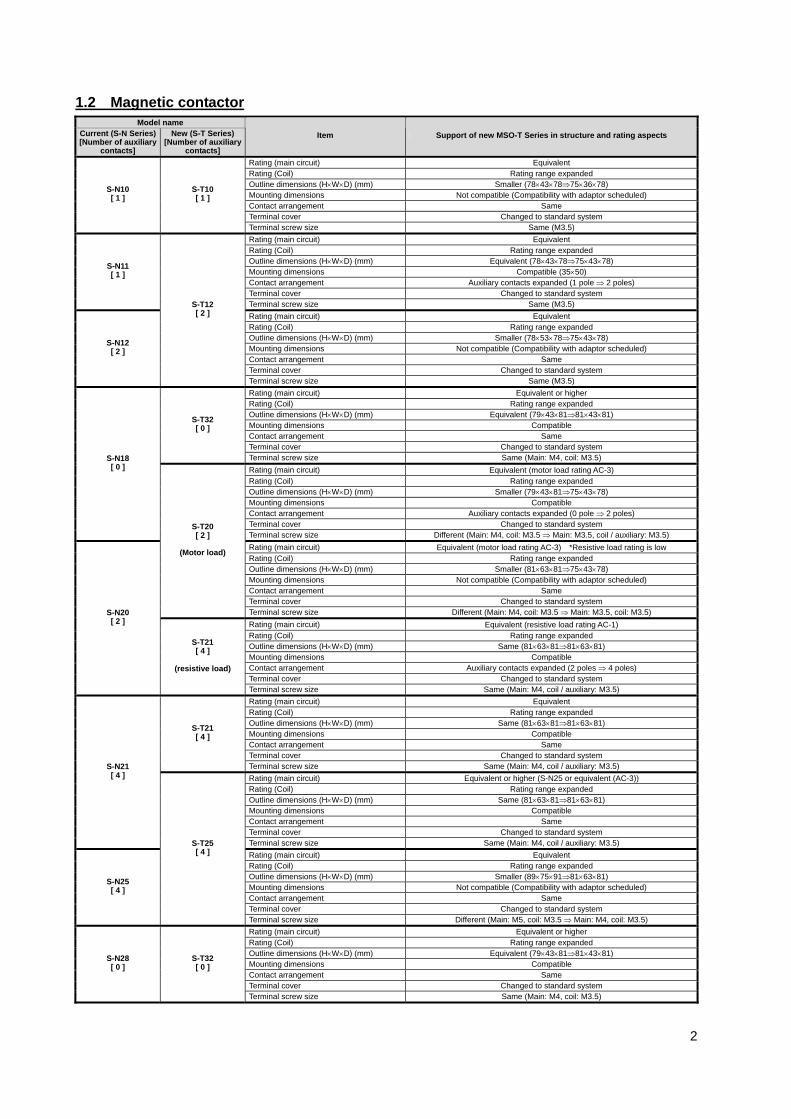
1.2 Magnetic contactor Model name
Current (S-N Series) [Number of auxiliary
contacts]
New (S-T Series) [Number of auxiliary
contacts]
Item Support of new MSO-T Series in structure and rating aspects
Rating (main circuit) Equivalent Rating (Coil) Rating range expanded Outline dimensions (H×W×D) (mm) Smaller (78×43×78⇒75×36×78) Mounting dimensions Not compatible (Compatibility with adaptor scheduled) Contact arrangement Same Terminal cover Changed to standard system
S-N10 [ 1 ]
S-T10 [ 1 ]
Terminal screw size Same (M3.5) Rating (main circuit) Equivalent Rating (Coil) Rating range expanded Outline dimensions (H×W×D) (mm) Equivalent (78×43×78⇒75×43×78) Mounting dimensions Compatible (35×50) Contact arrangement Auxiliary contacts expanded (1 pole ⇒ 2 poles) Terminal cover Changed to standard system
S-N11 [ 1 ]
Terminal screw size Same (M3.5) Rating (main circuit) Equivalent Rating (Coil) Rating range expanded Outline dimensions (H×W×D) (mm) Smaller (78×53×78⇒75×43×78) Mounting dimensions Not compatible (Compatibility with adaptor scheduled) Contact arrangement Same Terminal cover Changed to standard system
S-N12 [ 2 ]
S-T12 [ 2 ]
Terminal screw size Same (M3.5) Rating (main circuit) Equivalent or higher Rating (Coil) Rating range expanded Outline dimensions (H×W×D) (mm) Equivalent (79×43×81⇒81×43×81) Mounting dimensions Compatible Contact arrangement Same Terminal cover Changed to standard system
S-T32 [ 0 ]
Terminal screw size Same (Main: M4, coil: M3.5) Rating (main circuit) Equivalent (motor load rating AC-3) Rating (Coil) Rating range expanded Outline dimensions (H×W×D) (mm) Smaller (79×43×81⇒75×43×78) Mounting dimensions Compatible Contact arrangement Auxiliary contacts expanded (0 pole ⇒ 2 poles) Terminal cover Changed to standard system
S-N18 [ 0 ]
Terminal screw size Different (Main: M4, coil: M3.5 ⇒ Main: M3.5, coil / auxiliary: M3.5) Rating (main circuit) Equivalent (motor load rating AC-3) *Resistive load rating is low Rating (Coil) Rating range expanded Outline dimensions (H×W×D) (mm) Smaller (81×63×81⇒75×43×78) Mounting dimensions Not compatible (Compatibility with adaptor scheduled) Contact arrangement Same Terminal cover Changed to standard system
S-T20 [ 2 ]
(Motor load)
Terminal screw size Different (Main: M4, coil: M3.5 ⇒ Main: M3.5, coil: M3.5) Rating (main circuit) Equivalent (resistive load rating AC-1) Rating (Coil) Rating range expanded Outline dimensions (H×W×D) (mm) Same (81×63×81⇒81×63×81) Mounting dimensions Compatible Contact arrangement Auxiliary contacts expanded (2 poles ⇒ 4 poles) Terminal cover Changed to standard system
S-N20 [ 2 ]
S-T21 [ 4 ]
(resistive load)
Terminal screw size Same (Main: M4, coil / auxiliary: M3.5) Rating (main circuit) Equivalent Rating (Coil) Rating range expanded Outline dimensions (H×W×D) (mm) Same (81×63×81⇒81×63×81) Mounting dimensions Compatible Contact arrangement Same Terminal cover Changed to standard system
S-T21 [ 4 ]
Terminal screw size Same (Main: M4, coil / auxiliary: M3.5) Rating (main circuit) Equivalent or higher (S-N25 or equivalent (AC-3)) Rating (Coil) Rating range expanded Outline dimensions (H×W×D) (mm) Same (81×63×81⇒81×63×81) Mounting dimensions Compatible Contact arrangement Same Terminal cover Changed to standard system
S-N21 [ 4 ]
Terminal screw size Same (Main: M4, coil / auxiliary: M3.5) Rating (main circuit) Equivalent Rating (Coil) Rating range expanded Outline dimensions (H×W×D) (mm) Smaller (89×75×91⇒81×63×81) Mounting dimensions Not compatible (Compatibility with adaptor scheduled) Contact arrangement Same Terminal cover Changed to standard system
S-N25 [ 4 ]
S-T25 [ 4 ]
Terminal screw size Different (Main: M5, coil: M3.5 ⇒ Main: M4, coil: M3.5) Rating (main circuit) Equivalent or higher Rating (Coil) Rating range expanded Outline dimensions (H×W×D) (mm) Equivalent (79×43×81⇒81×43×81) Mounting dimensions Compatible Contact arrangement Same Terminal cover Changed to standard system
S-N28 [ 0 ]
S-T32 [ 0 ]
Terminal screw size Same (Main: M4, coil: M3.5)

3
1.3 Contactor Relay Model name
Current (S-N Series) [Number of auxiliary
contacts]
New (S-T Series) [Number of auxiliary
contacts]
Item Support of new MSO-T Series in structure and rating aspects
Rating Equivalent Rating (Coil) Rating range expanded Outline dimensions (H×W×D) (mm) Equivalent (78×43×78⇒75×43×78) Mounting dimensions Compatible
Contact arrangement (Note 1) – ⇒ 5a
4a ⇒ 4a1b 3a1b ⇒ 3a2b 2a2b ⇒ 3a2b
Terminal cover Changed to standard system
SR-N4 [ 4 ]
Terminal screw size Same (M3.5) Rating (main circuit) Equivalent Rating (Coil) Rating range expanded Outline dimensions (H×W×D) (mm) Smaller (78×53×78⇒75×43×78) Mounting dimensions Not compatible (Compatibility with adaptor scheduled)
Contact arrangement (Note 1) 5a ⇒ 5a
4a1b ⇒ 4a1b 3a2b ⇒ 3a2b 2a3b ⇒ –
Terminal cover Changed to standard system
SR-N5 [ 5 ]
SR-T5 [ 5 ]
Terminal screw size Same (M3.5) Rating (main circuit) Equivalent Rating (Coil) Rating range expanded Outline dimensions (H×W×D) (mm) Equivalent (78×43×106⇒75×43×108) Mounting dimensions Compatible
Contact arrangement (Note 1)
8a ⇒ 9a 7a1b ⇒ 7a2b 6a2b ⇒ 7a2b 5a3b ⇒ 5a4b 4a4b ⇒ 5a4b
Terminal cover Changed to standard system
SR-N8 [ 8 ]
SR-T9 [ 9 ]
Terminal screw size Same (M3.5)
Note 1: The contact arrangement drawings are shown below.
Current (S-N Series) New (S-T Series) SR-N4 SR-N5 SR-N6 SR-T5 SR-T9
4a 5a 8a 5a 9a
7a1b
7a2b
4a1b 4a1b
3a1b
6a2b
3a2b 3a2b
5a3b 5a4b 2a2b
2a3b
4a4b

4
2. Comparison of MS-T and MS-N Models 2.1 Motor Starter (open type)
Category AC-3 rated capacity (kW)
Auxiliary contact (standard) MS-T Series MS-N Series
Model name 220 to 240VAC 380 to 440VAC MS-T MS-N Standard (with
terminal cover) With wiring
streamlining terminal
Standard (no terminal cover)
With CAN terminal
2.5 4 1a MSO-T10 MSO-T10BC MSO-N10 MSO-N10CX MSO-N11 MSO-N11CX 3.5 5.5 1a1b 1a MSO-T12 MSO-T12BC MSO-N12 MSO-N12CX
1a1b – MSO-N18 MSO-N18CX 4.5 7.5 1a1b
MSO-T20 MSO-T20BC MSO-N20 MSO-N20CX
5.5 11 2a2b MSO-T21 MSO-T21BC MSO-N21 MSO-N21CX
Non- reversing
7.5 15 2a2b MSO-T25 MSO-T25BC MSO-N25 MSO-N25CX 2.5 4 1a×2+2b MSO-2×T10 MSO-2×T10BC MSO-2×N10 MSO-2×N10CX 3.5 5.5 1a1b×2+2b 1a×2+2b MSO-2×T12 MSO-2×T12BC MSO-2×N11 MSO-2×N11CX
1a1b×2 2a2b×2 MSO-2×N18 MSO-2×N18CX 4.5 7.5 1a1b×2 MSO-2×T20 MSO-2×T20BC MSO-2×N20 MSO-2×N20CX 5.5 11 2a2b×2 MSO-2×T21 MSO-2×T21BC MSO-2×N21 MSO-2×N21CX
AC
ope
rate
d
Reversing
7.5 15 2a2b×2 MSO-2×T25 MSO-2×T25BC MSO-2×N25 MSO-2×N25CX
2.2 Magnetic contactor (open type) (1) Comparison of motor load ratings (Category AC-3)
Category AC-3 rated capacity (kW)
Auxiliary contact (standard) MS-T Series MS-N Series
Model name 220 to 240VAC 380 to 440VAC MS-T MS-N Standard (with
terminal cover) With wiring
streamlining terminal
Standard (no terminal cover)
With CAN terminal
11 9 1a S-T10 S-T10BC S-N10 S-N10CX S-N11 S-N11CX 13 12 1a1b 1a S-T12 S-T12BC S-N12 S-N12CX
18 18 1a1b S-T20 S-T20BC 22 22 2a2b S-T21 S-T21BC
S-N20, S-N21 S-N20CX, S-N21CX
Non- reversing
30 30 2a2b S-T25 S-T25BC S-N25 S-N25CX 11 9 1a×2+2b S-2×T10 S-2×T10BC S-2×N10 S-2×N10CX 13 12 1a1b×2+2b 1a×2+2b S-2×T12 S-2×T12BC S-2×N11 S-2×N11CX 18 18 1a1b×2 S-2×T20 S-2×T120BC S-2×N20 S-2×N20CX 22 22 2a2b×2 S-2×T21 S-2×T21BC S-2×N21 S-2×N21CX
AC
ope
rate
d
Reversing
30 30 2a2b×2 S-2×T25 S-2×T25BC S-2×N25 S-2×N25CX 18 16 S-N18 S-N18CX 26 17 S-N28 S-N28CX Non-
reversing 32 32
– S-T32 S-T32BC – –
18 16 S-2×N18 S-2×N18CX 26 17 S-2×N28 S-2×N28CX M
ain
circ
uit
3-po
les
Reversing 32 32
– S-2×T32 S-2×T32BC – –
(2) Comparison of resistive load ratings (Category AC-1) Category AC-1 rated capacity (A)) Auxiliary contact
(standard) MS-T Series MS-N Series Model name
100 to 240VAC 380 to 440VAC MS-T MS-N Standard (with terminal cover)
With wiring streamlining
terminal Standard (no
terminal cover) With CAN terminal
20 11 1a S-T10 S-T10BC S-N10 S-N10CX 1a1b 1a S-T12 S-T12BC S-N11 S-N11CX 20 13 1a1b S-T12, S-T20 S-T12BC, S-T20BC S-N12 S-N12CX
1a1b – – S-N20 S-N20CX
Non- reversing
32 32 2a2b S-T21, S-T25 S-T21BC, S-T25BC S-N21 S-N21CX
20 11 1a×2+2b S-2×T10 S-2×T10BC S-2×N10 S-2×N10CX 1a1b×2+2b 1a×2 S-2×T12 S-2×T12BC S-2×N11 S-2×N11CX
20 13 1a1b×2 S-2×T12 S-2×T20
S-2×T12BC S-2×T120BC – –
1a1b×2 – – S-2×N20 S-2×N20CX
AC
ope
rate
d
Reversing
32 32 2a2b×2 S-2×T21 S-2×T25
S-2×T21BC S-2×T25BC S-2×N21 S-2×N21CX
25 20 S-N18 S-N18CX 30 30 S-N28 S-N28CX Non-
reversing 32 32
– S-T32 S-T32BC – –
25 20 S-2×N18 S-2×N18CX 30 30 S-2×N28 S-2×N28CX M
ain
circ
uit
3-po
le
Reversing 32 32
– S-2×T32 S-2×T32BC – –
2.3 Thermal Overload Relay TH-T Series TH-N Series
Type Heater designation Standard (with terminal cover)
With wiring streamlining
terminal Standard (no
terminal cover) With CAN terminal
0.12 to 11A TH-N12 TH-N12 1.3 to 15A
TH-T18 TH-T18BC TH-N18 TH-N18
0.24 to 15A TH-N20 TH-N20 22A
TH-T25 TH-25BC TH-N20TA TH-N20TACX
With 2-elements
29A – (TH-N Series production is continued) TH-N20TA TH-N20TACX 0.12 to 11A TH-N12 TH-N12 1.3 to 15A
TH-T18 TH-T18BC TH-N18 TH-N18
0.24 to 15A TH-N20 TH-N20 22A TH-T25 TH-25BC TH-N20TA TH-N20TACX
With 3-elements
29A – (TH-N Series production is continued) TH-N20TA TH-N20TACX
5
2.4 Contactor Relay Contact arrangement SR-T Series SR-N Series
Model name SR-T Series SR-N Series Standard (with
terminal cover) With wiring
streamlining terminal
Standard (no terminal cover)
With CAN terminal
4a, 3a1b, 2a2b SR-N4 SR-N4CX 5a, 4a1b, 3a2b 5a, 4a1b, 3a2b, 2a3b
SR-T5 SR-T5BC SR-N5 SR-N5CX
8a, 7a1b, 6a2b,
AC oper-ated 8a, 7a2b, 5a4b
5a3b, 4a4b SR-T9 SR-T9BC SR-N8 SR-N8CX
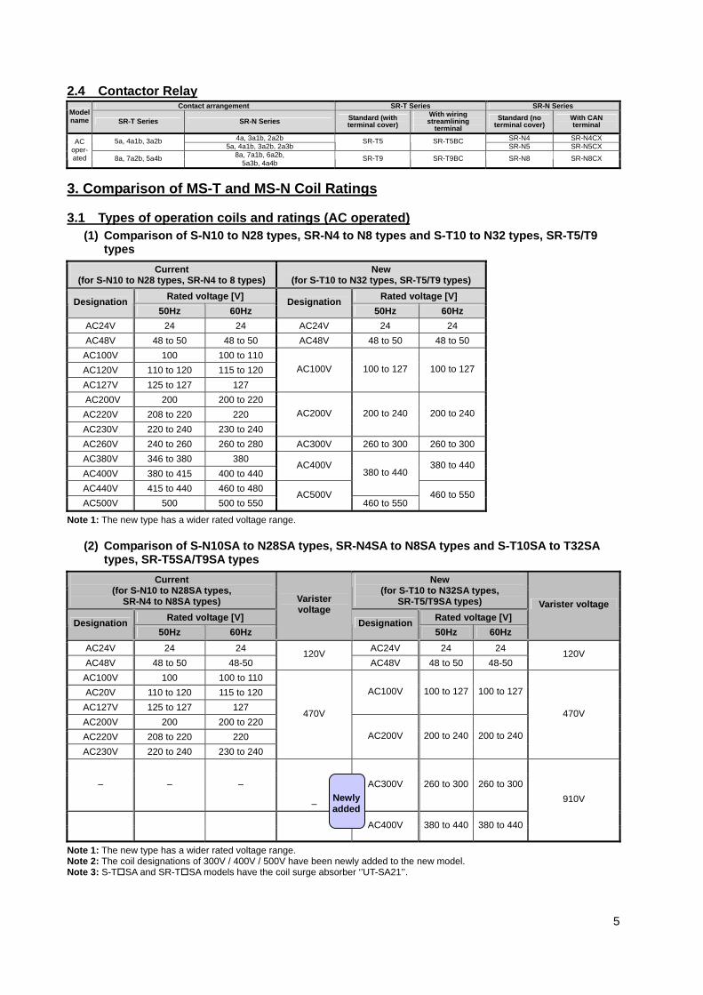
3. Comparison of MS-T and MS-N Coil Ratings 3.1 Types of operation coils and ratings (AC operated)
(1) Comparison of S-N10 to N28 types, SR-N4 to N8 types and S-T10 to N32 types, SR-T5/T9 types
Current (for S-N10 to N28 types, SR-N4 to 8 types)
New (for S-T10 to N32 types, SR-T5/T9 types)
Rated voltage [V] Rated voltage [V] Designation 50Hz 60Hz
Designation50Hz 60Hz
AC24V 24 24 AC24V 24 24 AC48V 48 to 50 48 to 50 AC48V 48 to 50 48 to 50
AC100V 100 100 to 110 AC120V 110 to 120 115 to 120 AC127V 125 to 127 127
AC100V 100 to 127 100 to 127
AC200V 200 200 to 220 AC220V 208 to 220 220 AC230V 220 to 240 230 to 240
AC200V 200 to 240 200 to 240
AC260V 240 to 260 260 to 280 AC300V 260 to 300 260 to 300AC380V 346 to 380 380 AC400V 380 to 415 400 to 440
AC400V 380 to 440
AC440V 415 to 440 460 to 480
380 to 440
AC500V 500 500 to 550 AC500V
460 to 550 460 to 550
Note 1: The new type has a wider rated voltage range.
(2) Comparison of S-N10SA to N28SA types, SR-N4SA to N8SA types and S-T10SA to T32SA types, SR-T5SA/T9SA types
Current (for S-N10 to N28SA types,
SR-N4 to N8SA types)
New (for S-T10 to N32SA types,
SR-T5/T9SA types) Rated voltage [V] Rated voltage [V] Designation
50Hz 60Hz
Varister voltage
Designation50Hz 60Hz
Varister voltage
AC24V 24 24 AC24V 24 24 AC48V 48 to 50 48-50
120V AC48V 48 to 50 48-50
120V
AC100V 100 100 to 110 AC20V 110 to 120 115 to 120
AC127V 125 to 127 127
AC100V 100 to 127 100 to 127
AC200V 200 200 to 220 AC220V 208 to 220 220 AC230V 220 to 240 230 to 240
470V
AC200V 200 to 240 200 to 240
470V
– – –
–
AC300V 260 to 300 260 to 300
AC400V 380 to 440 380 to 440
910V
Note 1: The new type has a wider rated voltage range. Note 2: The coil designations of 300V / 400V / 500V have been newly added to the new model. Note 3: S-T SA and SR-T SA models have the coil surge absorber ‘’UT-SA21’’.
Newly added

6
4. Changes to Product Indication 4.1 Indication of terminal number
Item MS-T typical model New MS-T Series Current MS-N Series Remarks
Main terminal numbers
S-T10 to T32 TH-T18, T25
Power side: 1/L1 3/L2 5/L3 Load side: 2/T1 4/T2 6/T3
Power side: 1/L1 3/L2 5/L3 Load side: 2/T1 4/T2 6/T3
S-T10, T12, T20
a contact: 13NO-14NO b contact: 21NC-22NC
a contact: 13NO-14NO b contact: 21NC-22NC Auxiliary
terminal number
(magnetic contactor)
S-T21, T25 a contatct: 13NO-14NO 43NO-44NO b contact: 21NC-22NC 31NC-32NC
a contact: 13NO-14NO 43NO-44NO b contact: 21NC-22NC 31NC-32NC
NO (Normally Open): a contact NC (Normally Closed): b contact
SR-T5 • 1st place of number: a contact: 3-4 b contact: 1-2 • 10th place of number: Changes between 1 and 5Example: SR-T5 3a2b
• 1st place of number: a contact: 3-4 b contact: 1-2 • 10th place of number: Changes between 0 and 4 Example: SR-N5 3a2b
Complies with international standards IEC
Auxiliary terminal number
(Contactor relay)
SR-T9 • 1st place of number: a contact: 3-4 b contact: 1-2 • 10th place of number: Changes between 1 and 9Example: SR-T9 5a4b
• 1st place of number: a contact: 3-4 b contact: 1-2 • 10th place of number: Changes between 1 and 9 Example: SR-N8 5a3b
Indi
cate
d in
form
atio
n
Coil terminal number
All models A1, A2 (Embossed charters)
A1, A2 (Printed together with coil rating indication)
S-T10 to T20 SR-T5/T9 UT-AX4
• Laser-printed onto case • Printed in blue onto arc cover of main unit (last line of SR-N8)
• Terminal number printed in blue on paper label attached on upper line of SR-N8 (auxiliary contact unit)
Indi
catio
n po
sitio
n
Terminal number
S-T21/T25/ T32
• Laser-printed onto front cover
• Printed in blue on arc cover

7
4.2 Indication of rating
Item MS-T typical model MS-T Series MS-N Series Remarks
Main circuit rating
S-T10 to T32 SR-T5, T9
All information laser-printed onto side
• 1=Ith rating (A) printed on lower left of front fece
• Other ratings are printed on side label
Indi
catio
n m
etho
d Coil rating S-T10 to T32 SR-T5, T9
All information is laser printed (no color-coding)
• Designation 100V/200V are printed with all rating ranges color-coded (Between coil terminals on power side) 100V 50Hz 100-110V 60Hz 200V 50Hz
• For all other ratings, the entire rating range is printed in white
4.3 Indication of model name
Item MS-T typical model MS-T Series MS-N Series Remarks
S-T10 to T20 SR-T5
Laser-printed onto front left of case
Printed in blue onto center left of arc cover
Indi
catio
n m
etho
d Model name
S-T21, T25, T32
Laser-printed onto front left of front cover
Printed in blue onto left center of arc cover
5. Wiring Related Differences 5.1 Terminals and Layout
Item MS-T typical model MS-T Series MS-N Series Remarks
Coil terminal layout
S-T10 to T32
Both terminals are arranged on power side
Both terminals are arranged on power side
S-T10 to T25 SR-T5
a contact
b contact
a contact
b contact
Indication of contact mark for auxiliary terminal (indicated with stamp, etc., on contactor / terminal)
SR-T9 Lower line (main unit side)
a contact
b contact
Upper line (auxiliary contact
block side) a contact
b contact
Lower line (main unit side)
a contact
b contact
Upper line (auxiliary contact
block side) a contact
b contact

8
5.2 Wire and solderless terminal size
Model
Operating
circuit
Dimension of
terminal portion
A x B x C
[㎜](Note 1)
Screw
size
Screw
type
cross solt
screw with
pressure
plate
Main
circuit
Operating
circuit
SR-N4/5/8 - - - - 1~2.5
SR-T5/9 - - - - 0.75~2.5
S-N10 8×5.2×4.5 M3.5×7 1~2.5 1~2.5
S-T10 7.5×3.7×4.5 M3.5×7 0.75~2.5 0.75~2.5
S-N11 8×5.2×4.5 M3.5×7 1~2.5 1~2.5
S-N12 8×5.2×4.5 M3.5×7 1~2.5 1~2.5
S-T12 7.5×3.7×4.5 M3.5×7 0.75~2.5 0.75~2.5
S-N18 1~6 1~2.5
S-N20 1~6 1~2.5
S-T20 7.5×3.7×4.5 M3.5×7 0.75~2.5 0.75~2.5
S-N21 10.5×5.2×5.5 M4×10.5 1~6 1~2.5
S-T21 10.5×5.2×5.5 M4×10.5 1.25~6 0.75~2.5
S-N25 13×5.5×6.5 M5×14 terminal screw2~16
Note11~2.5
S-T25 10.5×5.2×5.5 M4×10.5cross slot screw with
pressure plate1.25~6 0.75~2.5
S-N28 10.5×5.2×5.5 M4×10.5 1~6 1~2.5
S-T32 10.5×5.2×5.5 M4×10.5 1.25~6 0.75~2.5
TH-N12(Load side) 8×4×4 M3.5×7 1~2.5 1~2.5
TH-N18(Load side) 10.2×5×5 M4×10.5 1~6 1~2.5
TH-T18(Load side) 7.5×4×4 M3.5×7 0.75~2.5 0.75~2.5
TH-N20
(Power side/Load side)
10.2×6.8×5/
10.2×5.7×5
M4×10.5/
M4×10.5
cross slot screw with
pressure plate1~6 1~2.5
TH-N20TA(Load side) 13×5.8×6 M5×14 terminal screw2~16
Note11~2.5
TH-T25
(Power side/Load side)
10.2×6.8×5/
10.2×5.7×5
M4×10.5/
M4×10.5
cross slot screw with
pressure plate1.25~6 0.75~2.5
Terminal dimension and size/type of screw
Main circuit
Applicable electric wire
size
[㎜2]
Standard type
Contactor Relays
Magnetic Contactors
Thermal Overload Relays
10.5×5.2×5.5
cross slot screw with pressure
plate
cross slot screw with pressure
plate
M4×10.5cross slot screw with pressure
plate
M3.5×7
M3.5×7
M3.5×7
M3.5×7
M3.5×7
M3.5×7
M3.5×7
cross slot screw with pressure
plate
cross slot screw with pressure
plate
cross slot screw with pressure
plate
M3.5×7
M3.5×7
Note1.Customers needs to use pressure plate when wiring electrical wire directly.

9
6. Application of Thermal Overload Relay and Optional Units 6.1 Combination of Thermal Overload Relays and Optional Units
Model Thermal Overload
Relay
Additional auxiliary contact
block Mechanical interlocks
External surge absorber unit
Connection conductor
kit
TH- T18
TH- T25 UT-AX4 UT-
ML11UN-
ML21UT-
SA21UT-
SA23UT-
SA25
Product with coil
surge absorber
(SA) UN-TH21
Combina-tion with
TH-N type thermal
relay
S-T10 – – – – S-T12 – – – – S-T20 – – – – S-T21 – – – S-T25 – – – S-T32 – – – – – S-2×T10 – – – – S-2×T12 – – – – S-2×T20 – – – – S-2×T21 – – – S-2×T25 – – – S-2×T32 – – – – –
Note 1: : Applicable –: Not applicable : Standard combination product Note 2: Shaded cells indicate MS-T Series Thermal Overload Relay and Optional Units. Note 3: The optional units are dedicated for the MS-T Series, and is not compatible with the MS-N Series. 7.About coil and contacts replacement
Item MS-N(S-N10~28) MS-T(S-T10~S-T32)Coil replacement Possible Impossible
Contacts replacement Possible Impossible
10
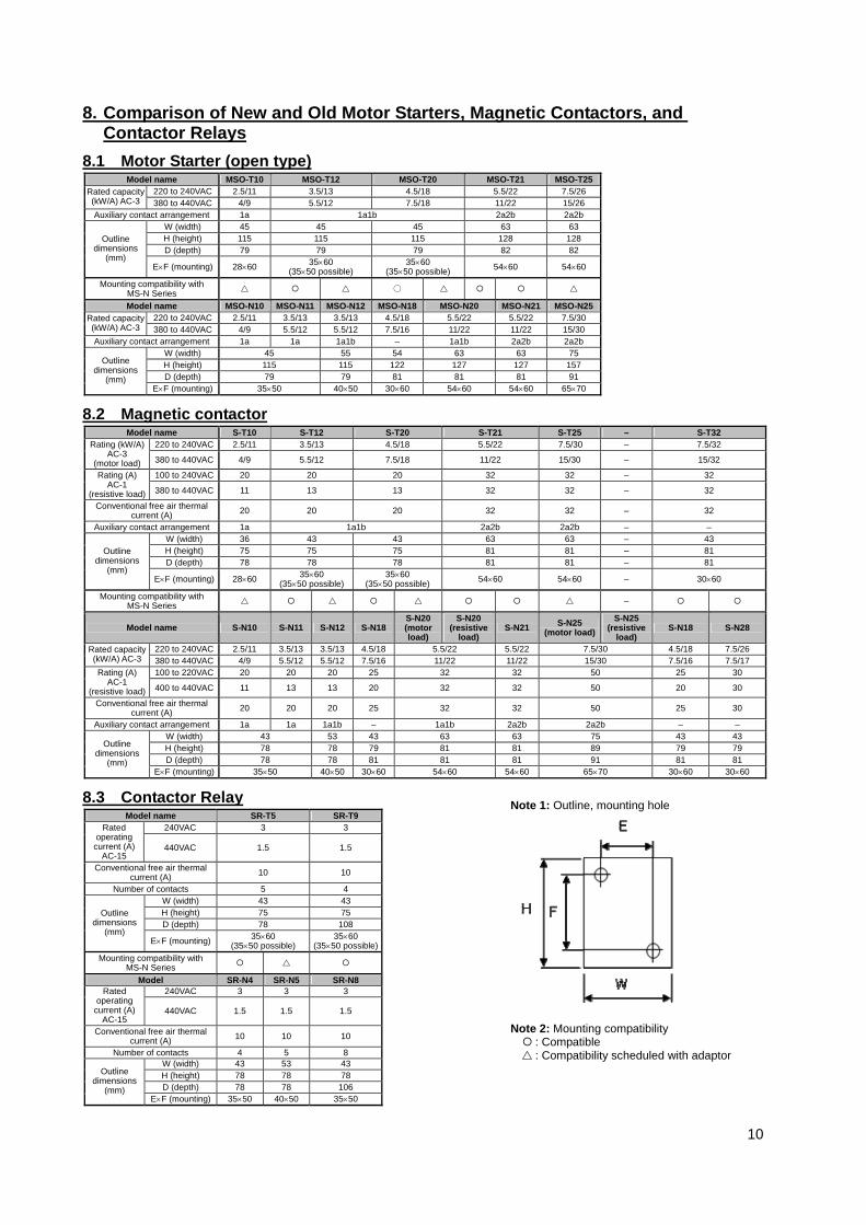
8. Comparison of New and Old Motor Starters, Magnetic Contactors, and Contactor Relays
8.1 Motor Starter (open type) Model name MSO-T10 MSO-T12 MSO-T20 MSO-T21 MSO-T25
220 to 240VAC 2.5/11 3.5/13 4.5/18 5.5/22 7.5/26 Rated capacity (kW/A) AC-3 380 to 440VAC 4/9 5.5/12 7.5/18 11/22 15/26 Auxiliary contact arrangement 1a 1a1b 2a2b 2a2b
W (width) 45 45 45 63 63 H (height) 115 115 115 128 128 D (depth) 79 79 79 82 82
Outline dimensions
(mm) E×F (mounting) 28×60 35×60
(35×50 possible) 35×60
(35×50 possible) 54×60 54×60
Mounting compatibility with MS-N Series ○
Model name MSO-N10 MSO-N11 MSO-N12 MSO-N18 MSO-N20 MSO-N21 MSO-N25220 to 240VAC 2.5/11 3.5/13 3.5/13 4.5/18 5.5/22 5.5/22 7.5/30 Rated capacity
(kW/A) AC-3 380 to 440VAC 4/9 5.5/12 5.5/12 7.5/16 11/22 11/22 15/30 Auxiliary contact arrangement 1a 1a 1a1b – 1a1b 2a2b 2a2b
W (width) 45 55 54 63 63 75 H (height) 115 115 122 127 127 157 D (depth) 79 79 81 81 81 91
Outline dimensions
(mm) E×F (mounting) 35×50 40×50 30×60 54×60 54×60 65×70
8.2 Magnetic contactor Model name S-T10 S-T12 S-T20 S-T21 S-T25 – S-T32
220 to 240VAC 2.5/11 3.5/13 4.5/18 5.5/22 7.5/30 – 7.5/32 Rating (kW/A) AC-3
(motor load) 380 to 440VAC 4/9 5.5/12 7.5/18 11/22 15/30 – 15/32
100 to 240VAC 20 20 20 32 32 – 32 Rating (A) AC-1
(resistive load) 380 to 440VAC 11 13 13 32 32 – 32
Conventional free air thermal current (A) 20 20 20 32 32 – 32
Auxiliary contact arrangement 1a 1a1b 2a2b 2a2b – – W (width) 36 43 43 63 63 – 43 H (height) 75 75 75 81 81 – 81 D (depth) 78 78 78 81 81 – 81
Outline dimensions
(mm) E×F (mounting) 28×60 35×60
(35×50 possible) 35×60
(35×50 possible) 54×60 54×60 – 30×60
Mounting compatibility with MS-N Series –
Model name S-N10 S-N11 S-N12 S-N18S-N20 (motor load)
S-N20 (resistive
load) S-N21 S-N25
(motor load)S-N25
(resistive load)
S-N18 S-N28
220 to 240VAC 2.5/11 3.5/13 3.5/13 4.5/18 5.5/22 5.5/22 7.5/30 4.5/18 7.5/26 Rated capacity (kW/A) AC-3 380 to 440VAC 4/9 5.5/12 5.5/12 7.5/16 11/22 11/22 15/30 7.5/16 7.5/17
100 to 220VAC 20 20 20 25 32 32 50 25 30 Rating (A) AC-1
(resistive load) 400 to 440VAC 11 13 13 20 32 32 50 20 30
Conventional free air thermal current (A) 20 20 20 25 32 32 50 25 30
Auxiliary contact arrangement 1a 1a 1a1b – 1a1b 2a2b 2a2b – – W (width) 43 53 43 63 63 75 43 43 H (height) 78 78 79 81 81 89 79 79 D (depth) 78 78 81 81 81 91 81 81
Outline dimensions
(mm) E×F (mounting) 35×50 40×50 30×60 54×60 54×60 65×70 30×60 30×60
8.3 Contactor Relay Model name SR-T5 SR-T9
240VAC 3 3 Rated operating
current (A) AC-15
440VAC 1.5 1.5
Conventional free air thermal current (A) 10 10
Number of contacts 5 4 W (width) 43 43 H (height) 75 75 D (depth) 78 108
Outline dimensions
(mm) E×F (mounting) 35×60
(35×50 possible) 35×60
(35×50 possible)Mounting compatibility with
MS-N Series
Model SR-N4 SR-N5 SR-N8 240VAC 3 3 3 Rated
operating current (A)
AC-15 440VAC 1.5 1.5 1.5
Conventional free air thermal current (A) 10 10 10
Number of contacts 4 5 8 W (width) 43 53 43 H (height) 78 78 78 D (depth) 78 78 106
Outline dimensions
(mm) E×F (mounting) 35×50 40×50 35×50
Note 1: Outline, mounting hole
Note 2: Mounting compatibility : Compatible
: Compatibility scheduled with adaptor

11
9. Outline Dimensions 9.1 Motor Starter (non-reversing)
MS-T Series MS-N Series MSO-T10 MSO-N10
MSO-T12 MSO-N11
MSO-N12
2-M4 screw mounting hole
M3.5 screw
(Reset bar)
28 (mounting dimension)
60 (m
ount
ing
dim
ensi
on)
2-M4 screw mounting hole
M3.5 screw
Reset bar (reset stroke 2.5mm)
50 (m
ount
ing
dim
ensi
on)
(mounting dimension)
(Reset bar)
Operation indication (manual trip)
M3.5 screw
35mm wide rail
(For 7.5mm thick rail)
2-M4 screw mounting hole
M3.5 screw
35 (mounting dimension)
60 (m
ount
ing
dim
ensi
on)
(mounting dimension)
50 (m
ount
ing
dim
ensi
on)
2-M4 screw mounting hole
M3.5 screw
Reset bar (reset stroke 2.5mm)
50 (m
ount
ing
dim
ensi
on)
(mounting dimension)
(Reset bar)
Operation indication (manual trip)
M3.5 screw
35mm wide rail
(For 7.5mm thick rail)
2-M4 screw mounting hole
M3.5 screw
Reset bar (reset stroke 2.5mm)
50 (m
ount
ing
dim
ensi
on)
(mounting dimension)
(Reset bar) Operation indication (manual trip) M3.5 screw
35mm wide rail
(For 7.5mm thick rail)
12
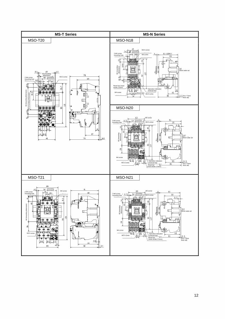
MS-T Series MS-N Series
MSO-T20 MSO-N18
MSO-N20
MSO-T21 MSO-N21
2-M4 screw mounting hole
M3.5 screw
35 (mounting dimension)
60 (m
ount
ing
dim
ensi
on)
50 (m
ount
ing
dim
ensi
on)
(mounting dimension)
2-M4 screw mounting hole M3.5 screw
Reset bar
60 (m
ount
ing
dim
ensi
on)
(mounting dimension)
Operation indication (manual trip) M3.5 screw
35mm wide rail
(For 7.5mm thick rail)
M4 screw
(reset stroke 2.5mm)
M4 screw
2-M4 screw mounting hole
M3.5 screw
60 (m
ount
ing
dim
ensi
on)
(mounting dimension) M4 screw
2-M4 screw mounting hole
M3.5 screw
Reset bar (reset stroke 2.5mm)
60 (m
ount
ing
dim
ensi
on)
(mounting dimension)
(Reset bar)
Operation indication (manual trip)
M3.5 screw
35mm wide rail
(For 7.5mm thick rail)
M4 screw
M4 screw
2-M4 screw mounting hole M3.5 screw
Reset bar
60 (m
ount
ing
dim
ensi
on)
(mounting dimension)
Operation indication (manual trip)
35mm wide rail
(For 7.5mm thick rail)
(reset stroke 2.5mm)
M4 screw
M3.5 screw
M4 screw

13
MS-T Series MS-N Series
MSO-T25 MSO-N25 (up to 15A designation)
MSO-N25 (22A designation)
2-M4 screw mounting hole
M4 screw
60 (m
ount
ing
dim
ensi
on)
(mounting dimension)
M3.5 screw
2-M4 screw mounting hole
M3.5 screw
(mou
ntin
g di
men
sion
)
(mounting dimension)
Operation indication (manual trip)
M3.5 screw
35mm wide rail
(For 7.5mmthick rail)
M5 screw (with washer, spring washer)
M4 screw
M3.5 screw
Reset bar (reset stroke 2.5mm)
2-M4 screw mounting hole
M3.5 screw
(mou
ntin
g di
men
sion
)
(mounting dimension)
Operation indication (manual trip)
M3.5 screw
35mm wide rail
(For 7.5mm thick rail)
M5 screw (with washer, spring washer)
M4 screw
Reset bar (reset stroke 2.5mm)
M5 screw (with washer, spring washer)

14
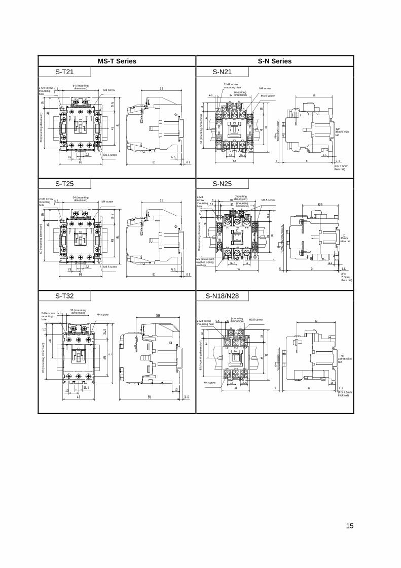
9.2 Magnetic contactor (non-reversing) MS-T Series S-N Series
S-T10 S-N10
S-T12 S-N11
S-N12
S-T20 S-N20
2-M4 screw mounting hole
M3.5 screw
28 (mounting dimension)
60 (m
ount
ing
dim
ensi
on)
2-M4 screw mounting hole
M3.5 screw
50 (m
ount
ing
dim
ensi
on)
(mounting dimension)
35mm wide rail
(For 7.5mm thick rail)
2-M4 screw mounting hole
M3.5 screw
35 (mounting dimension)
60 (m
ount
ing
dim
ensi
on)
50 (m
ount
ing
dim
ensi
on)
(mounting dimension)
2-M4 screw mounting hole
M3.5 screw 50
(mou
ntin
g di
men
sion
)
(mounting dimension)
35mm wide rail
(For 7.5mm thick rail)
2-M4 screw mounting hole
M3.5 screw
50 (m
ount
ing
dim
ensi
on)
(mounting dimension)
35mm wide rail
(For 7.5mm thick rail)
2-M4 screw mounting hole
M3.5 screw
60 (m
ount
ing
dim
ensi
on)
(mounting dimension)
35mm wide rail
(For 7.5mm thick rail)
M4 screw 2-M4 screw mounting hole
M3.5 screw
35 (mounting dimension)
60 (m
ount
ing
dim
ensi
on)
50 (m
ount
ing
dim
ensi
on)
(mounting dimension)
15
MS-T Series S-N Series
S-T21 S-N21
S-T25 S-N25
S-T32 S-N18/N28
2-M4 screw mounting hole
M4 screw 54 (mounting dimension)
60 (m
ount
ing
dim
ensi
on)
M3.5 screw
2-M4 screw mounting hole
M3.5 screw
50 (m
ount
ing
dim
ensi
on)
(mounting dimension)
35mm wide rail
(For 7.5mm thick rail)
M4 screw
2-M4 screw mounting hole
M4 screw 54 (mounting dimension)
60 (m
ount
ing
dim
ensi
on)
M3.5 screw
2-M4 screw mounting hole
M3.5 screw 70
(mou
ntin
g di
men
sion
) (mounting dimension)
35mm wide rail
(For 7.5mmthick rail)
(mounting dimension)
M5 screw (with washer, spring washer)
2-M4 screw mounting hole
M4 screw 30 (mounting dimension)
60 (m
ount
ing
dim
ensi
on)
2-M4 screw mounting hole
M3.5 screw
60 (m
ount
ing
dim
ensi
on)
(mounting dimension)
35mm wide rail
(For 7.5mmthick rail)
M4 screw
16
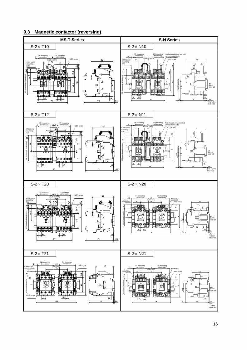
9.3 Magnetic contactor (reversing) MS-T Series S-N Series
S-2 × T10 S-2 × N10
S-2 × T12 S-2 × N11
S-2 × T20 S-2 × N20
S-2 × T21 S-2 × N21
4-M4 screw mounting hole
M3.5 screw
28 (mounting dimension)
60 (m
ount
ing
dim
ensi
on)
28 (mounting dimension)
(Built-in pitch) 4-M4 screw mounting hole
M3.5 screw
50 (m
ount
ing
dim
ensi
on)
35 (mounting dimension)
35mm wide rail
(For 7.5mmthick rail)
35 (mounting dimension)
(Built-in pitch)
Rod-shaped crimp terminal with insulation tube
4-M4 screw mounting hole
M3.5 screw
35 (mounting dimension)
60 (m
ount
ing
dim
ensi
on)
35 (mounting dimension)
(Built-in pitch) 4-M4 screw mounting hole
M3.5 screw
50 (m
ount
ing
dim
ensi
on)
35 (mounting dimension)
35mm wide rail
(For 7.5mmthick rail)
35 (mounting dimension)
(Built-in pitch)
Rod-shaped crimp terminal with insulation tube
4-M4 screw mounting hole
M3.5 screw 35 (mounting dimension)
60 (m
ount
ing
dim
ensi
on)
35 (mounting dimension)
(Built-in pitch)
4-M4 screw mounting hole M3.5 screw
60 (m
ount
ing
dim
ensi
on)
54 (mounting dimension)
35mm wide rail
(For 7.5mm thick rail)
54 (mounting dimension)
(Built-in pitch)M4 screw
4-M4 screw mounting hole M3.5 screw
60 (m
ount
ing
dim
ensi
on)
54 (mounting dimension)
35mm wide rail
(For 7.5mm thick rail)
54 (mounting dimension)
(Built-in pitch) M4 screw 4-M4 screw mounting hole
M4 screw
54 (mounting dimension)
60 (m
ount
ing
dim
ensi
on)
54 (mounting dimension)
(Built-in pitch)
M3.5 screw

17
MS-T Series MS-N Series
S-2 × T25 S-2 × N25
S-2 × T32 S-2 × N18/N28
4-M4 screw mounting hole
M4 screw
54 (mounting dimension)
60 (m
ount
ing
dim
ensi
on)
54 (mounting dimension)
(Built-in pitch)
M3.5 screw
3-M4 screw mounting hole
M3.5 screw
(mou
ntin
g di
men
sion
)
(mounting dimension)
75 (mounting dimension)
4-M4 screw mounting hole
M4 screw
30 (mounting dimension)
(mou
ntin
g di
men
sion
)
(Built-in pitch)
M3.5 screw
30 (mounting dimension)
4-M4 screw mounting hole
M3.5 screw 60
(mou
ntin
g di
men
sion
) 30 (mounting dimension)
35mm wide rail
(For 7.5mmthick rail)
(Built-in pitch)
M4 screw
(mounting dimension)

18
9.4 Thermal Overload Relay TH-T Series TH-N Series
TH-T18 TH-N12
TH-N18
TH-T25 TH-N20
TH-N20TA (22A
designation)
M3.5 screw
Reset bar (reset stroke 2.5mm)
Operation indication (manual trip)
M3.5 screw
Reset bar (reset stroke 2.5mm)
Operation indication (manual trip)
M3.5 screw
Reset bar (reset stroke 2.5mm)
Operation indication (manual trip)
M4 screw
M3.5 screw M4 screw
2-M4 screw mounting hole
33 (m
ount
ing
dim
ensi
on)
(mounting dimension)
2-M4 screw mounting hole
M3.5 screw
(mou
ntin
g di
men
sion
)
(mounting dimension)
M4 screw
Reset bar (reset stroke 2.5mm)
Operation indication (manual trip)
M3.5 screw
Reset bar (reset stroke 2.5mm)
Operation indication (manual trip)
M4 screw
M5 screw (with washer, spring washer)

19
9.5 Contactor Relay SR-T Series SR-N Series
SR-T5 SR-N4
SR-N5
SR-T9 SR-N8
M3.5 screw 2-M4 screw mounting hole
60 (m
ount
ing
dim
ensi
on)
35 (mounting dimension)
60 (mounting dimension)
50 (m
ount
ing
dim
ensi
on)
M3.5 screw
2-M4 screw mounting hole
50 (m
ount
ing
dim
ensi
on)
35 (mounting dimension)
35mm wide rail
(For 7.5mmthick rail)
M3.5 screw
2-M4 screw mounting hole
50 (m
ount
ing
dim
ensi
on)
40 (mounting dimension)
35mm wide rail
(For 7.5mmthick rail)
M3.5 screw 2-M4 screw mounting hole
60 (m
ount
ing
dim
ensi
on)
35 (mounting dimension)
30 (mounting dimension)
50 (m
ount
ing
dim
ensi
on)
M3.5 screw
2-M4 screw mounting hole
50 (m
ount
ing
dim
ensi
on)
35 (mounting dimension)
35mm wide rail
(For 7.5mmthick rail)