contact stresses in gear teeth-a new method · contact stresses in gear teeth - a new method of...
TRANSCRIPT

AD-A239 497
NASA AVSCOMTechnical Memorandum 104397 Technical Report 91 - C- 001AIAA 91-2022
Contact Stresses in GearTeeth-A New Methodof Analysis
Paisan Somprakit and Ronald L. HustonUniversity of CincinnatiCincinnati, Ohio
and
Fred B. OswaldLewis Research CenterCleveland, Ohio
BAUGl13 1994
Prepared for the27th Joint Propulsion Conferencecosponsored by the AIAA, SAE, ASME, and ASEESacramento, California, June 24-27, 1991
JApprovod fm uor.rejJ~ait-~i:m Un hL"ttt~l
US ARMY
AVATIONSY¢STEMS COMMANDSA AVIATION M4T ACTMTY
91-07590IfillillllJ~llillllllll~ll~Co q '3 1.2 o
CONTACT STRESSES IN GEAR TEETH
- A NEW METHOD OF ANALYSIS
Paisan Somprakit and Ronald L. Huston
Mechanical, Industrial, and Nuclear Engineering
University of Cincinnati
Cincinnati, Ohio 45221-0072
and
Fred B. Oswald
National Aeronautics Space Administration
Lewis Research Center
Cleveland, Ohio 44125
Abstract standard finite element procedures need to be
modified through the use of gap elements, large
This paper presents a new, innovative procedure numbers of elements, and iterative procedures
called point load superposition for determining the before they can be accurately applied in the study
contact stresses in mating gear teeth. It is of contact stresses. Such modifications, althoughbelieved that this procedure will greatly extend feasible,
4 are burdensome and not generally
both the range of applicability and the accuracy of available.
gear contact stress analyses.A relatively new and promising procedure for
Point load superposition is based upon funda- contact stress analysis is the boundary eLementmental solutions from the theory of elasticity. it method. The boundary element method is particu-is an iterative numerical procedure which has dis- larly useful in regions with high stress grad-tinct advantages over the classical Hertz method, ients - as with contact stresses. However, thisthe finite-element method (FEM), and over existing method is still under development and applicationsapplications with the boundary element method with contact stresses also require iterative proce-(BEM). Specifically, friction and sliding effects, dures to obtain the contact area geometry.which are either excluded from or difficult tostudy with the classical methods, are routinely In this paper we present a procedure dedicatedhandled with the new procedure, strictly to contact stress analysis with direct
application in gear tooth contact stress analys-s.
The paper presents the basic theory and algo- It is similar to the boundary element methcd. itrithms. Several examples are presented. Results does not require the restrictive assumptions of theare consistent with those of the classical Hertz analysis. That is, with this method, non-theories. Applications with spur gears are cylindrical geometry and frictional effects, asdiscussed, encountered in loaded meshing gears, are readily
accommodated. The method is based upon the point-Introduction load superposition method developed by Paul,""
and previous unpublished work of Sisera JayasingheGear tooth contact stress is the single most at the University of Cincinnati.
important factor affecting the life of a gear.Tooth contact stresses also have a significant Historically, contact stresses have been oneeffect upon tooth deformations and thus upon gear of the most important, most widely studied, and yetperformance under load. However, in spite of their most difficult problems in the theory of elasti-dominant role in gearing mechanics, contact city. Contact stress analysis can be traced backstresses are still not well understood and they are to the work of H. Hertz in 18811 _
3 who studied the
not accurately quantified. Contact stresses are contact deformation of smooth elastic bodiesnot nearly as well documented as, for example, root pressed together by forces normal to their contact-and fillet stresses. ing surfaces. He proposed that the contact region
could be modeled by an elastic half space loadedOne of the reasons that gear tooth contact over an elliptical area.
stresses are not better understood is that thegeometry and kinematics of meshing gear teeth do References 9 to 22 describe recent attempts tonot satisfy the assumptions required for the appli- use the finite element method and the boundary ele-cation of the classical and standard Hertzion con- ment method to determine contact stresses.tact stress analysis."
2,3 The Hertz analysis
assumes a contact between frictionless cylinders. The point-load superposition method presentedIt does not account for noncircular geometry such in this paper has been outlined in a paper pre-as involute geometry, and it does not include the sented at the Health Monitoring for Propulsionimportant friction forces which occur in gear con- Systems Conference in Cincinnati (1990). Thetact away from the pitch point, method is also documented in a recent NASA Con-
tractor Report of the authors. 4Standard finite element procedures are also
unsatisfactory for studying contact stresses. The balance of the paper is divided into nineContact stresses are in essence stress concentra- parts with the iollowing part sutnarizing some pre-tions which are locally nonlinear. Hence, the liminary results useful in the sequel. The next

three parts present the basic analysis. Numerical 2G x3 2G
procedures are then discussed followed by some ax. .-simple examples. The next part discusses appli- (z :(5)
cation with spur gears. The final two parts con- xz 2G x z
tain a discussion and concluding remarks. X __ , czx= -
(x Z z) if (x z Z
Preliminary Considerations
The displacement of a surface point are thenConsider two elastic bodies in contact. Let
the contact region be divided into a mesh of ele- (l_/1)
ments (or cells). Let the forces transmitted u, =-2G - InI xi c,
across each cell be represented by a distribution FE
of concentrated forces acting on an elastic halfspace. By using long-established results from the
theory of elasticity, together with the principle u = G_2
of superposition, the stress distribution and point
displacements due to a cell loading are obtained where c is a constant determined from a zero-
Then, by superposing the results from each cell the displacement reference point.
resulting stress and displacement distributionswithin the contacting bodies may be obtained. Next, consider an elastic half space with a
distributed normal and tangential loading over aTo develop the analysis consider an elastic portion of the surface as depicted in Fig. 2.
half space with a concentrated normal load as in
Fig. 1. Then the resulting stresses and displacements
at a typical point P may be obtained by super-Let P be a typical point within the half position (integration) of the foregoing results.
space, located by tha polar coordinates (r,6) as Following the analysis of Johnson,' the stresses
shown. Then the radial and tangential stresses at at P are:
P are:
2F L×× - _X{z ls l -
0 rr- 2 cos , ge =
= (1) s)7sFr
+ g(s) (x-s) ]/ (X-s) + z2] }ds
In rectangular coordinates, these stresses
have the form: U -
2F xz 2F + z'g(s)(x-s)]i (x-s) z ]i)dsF (x+Z)IT
(2)z 2F xz 2 or Z - b Q[z
2fs)lx-s )
Z 2
i 2(x+ zg(s)(x-s)+(/+(x-s) 4 z22ds
Using the stress-strain equations and thestrain-displacement equations, the displacements at In like manner the tangential and normal dis-
25a point P on the surface may be expressed as: placements of a surface point are: '
u - F 2E [ f f(s)ds - f(s)dsl2E (3)
1 11, 2 (I-LI-)u 2F In) h/x - g(s)Injx-sdsc,
where E and I/ are the elastic constant and u, = - 2(-I f% f(s)#njx-sjdsPoisson's ratio, and where h is the distance to a IE
reference point of zero displacement along the (i-2t2)(Ilv) g s ds
z-axis. 2+ g()d - g(s)ds] c.2E
In like manner, if there is a concentrated25
tangential force G, the stresses at P are: where c and c, are constants to be determined
from the displacement of an arbitrary reference0
r - i-cos , 0U8 - 6 0 - 0 (4) point.lrr
where 9 is now measured from the line of action
of force G. In rectangular coordinates these
stresses are
2

Application: Triangular Shape where C, and C. are constants to be determined
Loading Distribution from the displacements of a reference point andwhere A and B are defined as:
Equations (7) and (8) may be used to determine
the effects of the force distribution in the con- -(1 -
tact region. If the region is divided into a mesh A - __ 2lrEaof elements (or cells), then the effects of the
loadings on the individual cells may be super-
imposed. Moreover, the general loading in the con- ((132))(l+L)
tact region may be represented by the superimposed E for x > a
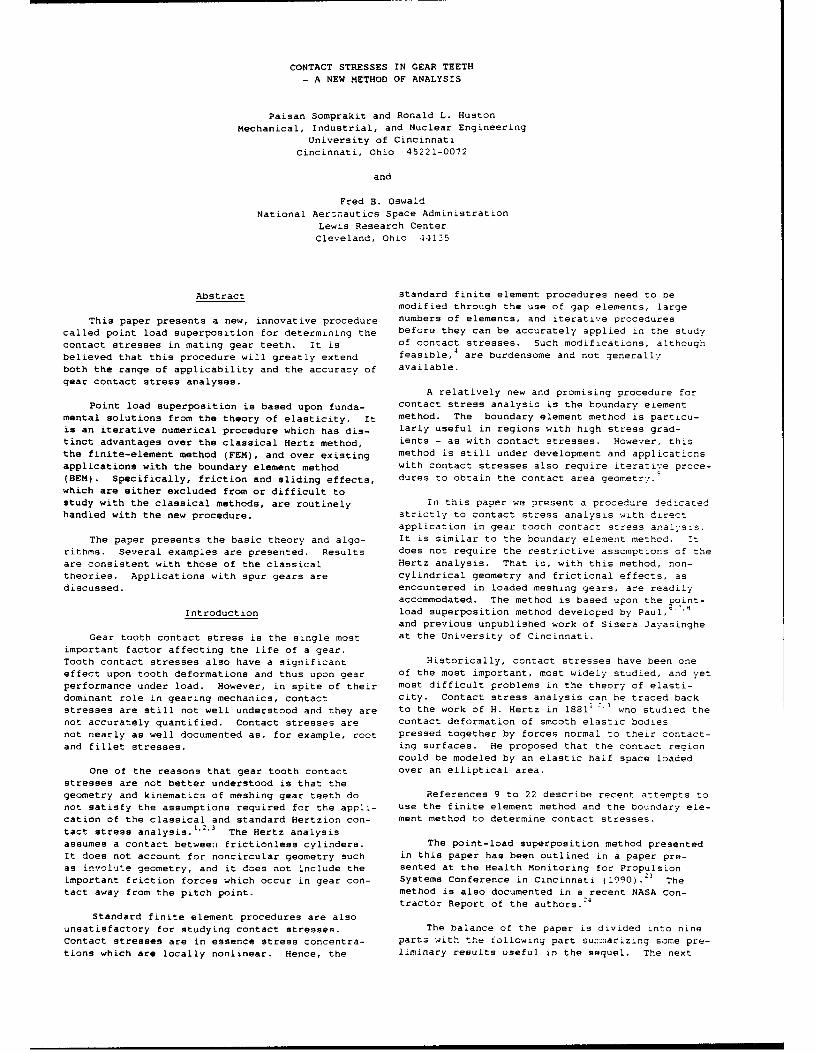
loadings on the cells. A triangular (that is, B
piecewise linear) loading distribution over a cell
forms a convenient basis for modelling the general -(-2L)(l4.wxa.Iai21 for lxi S a
loading distribution. Ea
The contribution of a triangular load on an
individual cell to the stress at a typical point
P may be obtained by letting f(x) and g(x) of Modeling of Contact Force Distribution
Eqs. (7) and (8) have the forms:To illustrate how these results can be
f(x) - f,(a-I x )/a , g(x) (9) superimposed in the contact region, suppose that
= g0 (a- I x I)/
a , I x S a the contact force distribution is represented bythe piecewise linear distribution, as in F~g. 4.
where a is the half-width of the cell whose Let the contact region be d~;.ved into n
center is at the origin, and where f0 and g. equal-width elements (or cells) as shown. Then,
are the peak triangular normal and tangential load- just as the region is discretized so also are the
ings as depicted in Fig. 3. force and displacement distributions. Let a bethe element half-width. Then the element nodal
By substituting from Eqs. (9) into (7) and by coordinates are in multiples of a. That is, the
performing the indicated integrations, the result- x-coordinate of node k is:
ing stresses at P (Fig. 3) are:25x. = ka (14)
fo
0 [ (xa xa)6 x 2zIn (r~r r')[(x-a). + ) -2 Let u and u represent the tangential
and normal displacements of node . due to a tri-
g, angular normal load centered at node J. Then fr-o
+ - [ (2xln(r.r,/r2) + 2aln(r/r.) Eq. (12), u,, and u may be expressed asha -- :(l2-2L") ( )
- 3z(8 1 +02 - 20)1 u - "'f f(15)
fo goz1-V
O0= ( (x-a) 0 4. (x+a) 2 - 2x) - +ra -20 u )c' fI a- E z
f z g "
a z - (01 + 02 -20) + - (x-a)Olar -a a
(x+a) 0 2xO + 2zln(rrr) ]0ln(k) + In(
(10) k=:i]
where r,, r2, r, 0,, 02, and 0 are given by -2an4=
(Fig. 3): F
2 2 2 2 2 2ri - (x-a) + z , r2 - (x+a) + Z, (16
2 2 2r - x + z
2, tan81 - z/(x-a), ()
tan0 2 - z/(x+a), tanO - z/x {a/. ' k>Od. - a , k<Oi
0 , k=O I
Similarly, the displacements of a surface
point are: rpoint agre (.a)
22~awhere k is defined as:
u. Ag o ( x + a )2 Jn (x a+ l ) 2
+ (x-a) 2 n(x/a- )2 k =i -j(17)
- 2x'#n(x/a)2J 4. Bf0 + CI
(12) Equation (15) may be used to obtain the dis- - 1
2 2 placements at node i due to a set of superposeduz *Afof(xa) i
n (x/a+l) 4 (x-a )
ln(x/a-1)' triangular lrid distributions centered at each ofthe nodes. In this case the terms c f and
2x 2n(x/a)21 - Bg0 + C. d fj are interpreted as sums over j.
S . .ty CodesI. and/o
3 Dist S oeata
E'r

Finally, if there is a horizontal or by the friction coefficient so that alternativelytangential loading, an analogous analysis leads to sliding occurs.displacements at node i as:
Figure 7 depicts the cylinders in contact with
S-12
(l-2V)(l+L() tangential loading. As before P, and P areS )cJgJ , u i d1 gg (18) matching surface points at the initiation of con-E E
tact. When the tangential load G is applied the
distant points Q, and Q2 have rigid body dis-where the coefficients c and d are the same placements dtx ani d2x relative to 0. If the
as those of Eq. (16) and ere there is a sum on j displacements of P1 and P2 relative to 0 are
from 1 to n. denoted by S x and S2x, the slip S. between P.and P2 may be defined as:
The displacements of Eqs. (15) and (18) aremeasured relating to a convenient reference point, S Sx -S. . (Ulx - d x) - (U x - d~x) (22)say the origin of the coordinate axes. - (Ul. - U2x) - (dl. - d_.)
Contact AnalysisIf P, and P, are in the nonslip (stick)
Equations (15) and (18) may be used to develop region s. is zero, and thenan iterative procedure for obtaining a detailed andcomprehensive analysis of contact stresses and Ux - Ux dx - dx - D. (23)
deformations.
where D is the global tangential displacement ofTo illustrate this consider two cylinders the cylinders.
pressed together as in Fig. 5. As the cylindersare brought together they initially have line con- Numerical Procedurestact. Then as they are pressed tighter the linecontact develops into a contact strip. Equations (15) and (18), together with the
constraint equations of the foregoing part, may beFigure 6 depicts the contact region after a used to determine the nodal normal and tangential
finite deformation. The solid curves represent the forces f, and g C A difficulty which arisesdeformed surface profiles, and the dashed curves however, is that the extent of the contact regionrepresent the undeformed, or original profiles. is not known a-priori. Hence, an iterative pro-
cedure needs to be developed which will determineConsider two points Q, and Q, relatively the contact region as well as the nodal forces.
distant from the contact region. Then during the
compression Q, and Q_ move toward the contact For the development of this procedure, it isregion and toward each other through the displace- convenient to superimpose Eqs. (15) and (1E) andments dz and d2 respectively, express them in the form:
Consider two typical matching surface points u, -g. (24)
- - U1. (2-P, and P, separated by a distance h(x). Then E Eas the deformation proceeds, P, and P, simulta-neously move toward each other and deform inward andinto their respective cylinders. Let U and U,I: 2(measured as positive into the respective cylin- (1-2V)(I+V) - g -1') - (25)ders) represent the z-axis displacements of P u -uZ z -- .! d
E Eand P toward Q, and Q,. Then if P and Pcome into contact,'we have
where c and d are defined asU1, + U.Z + h(x) - d:z + d , - Dz (19) 02 '2
6, - c, and d -- d,, - d,,where D is the global compressive displacementof the cylinders. If P and P are outside the
contact region we have where cq and d are influence coeffiz-,nts ofthe origin (Eqs. (16) and (17)). Then V, substi-
U , .1U2. h(x) > ) (20) tuting from Eqs. (24) and (25) into Ec ,201 we
haveEquations (19) and (20) can be used to deter-
mine the extent of the contact region. f, + X d, -b, i . 0 ... ,±n (27)
If there is no relative horizontal displace-ment of P, and P2' we have the no-slip condition where
22U,, -, (21) = ( -l I-Pd27 : • (I-2LI)(1+ /, .)
E, E, E, 28(28)When the cylinders are subjected to tangential 1-2L
loading in addition to the normal loading, the d('"2)deformation geometry depends upon the relative mag- E.nitudes of the normal and tangential loads. Thetangential loading causes an asymmetric deformation
pattern. This asymmetry, or distortion is limited
4

with E,, VI, E,, and I/, being the elastic con- axial length and no tangential loading. The cylin-
stants of Bodies 1 and 2. ders had radii: 100 and 150 in; elastic modulus:30xl0
6 lb/in"; and Poisson ratio: 0.3. The cylin-
Similarly, for those nodes in the stick region der surfaces were taken to be frictionless so that
Eqs. (24) and (25) together with Eq. (21) lead to a comparison could be made with the classical Hertzsolution, which assumes frictionless contact.
£]dif, - ) c 1 g j - 0(29) Table 1 shows a comparison of numerical
i=l. m; j=O,...,±n results and the Hertz solution.
Next to examine the effects of friction (and(1-2'.) (1,L1) (1-21/,)(1 +1/,) nence, the consequences of neglecting friction), we
XE, 5 considered two unlubricated cylinders with radii
- (30) 100 and 150 in. made of steel and aluminum respec-
(l-V) (I- tively. Different materials were chosen te illus-and .- _ --+ trate the effects of material properties on the
E, E. solutions. (The Hertz solution is based upon iden-tical material properties of the contacting
Finally, for those nodes in the slip region we bodies.) As in the first example, the cylinders
have were pressed together with a normal force of 1000lb per unit axial length. The elastic moduli for
gi = -n, .... p,p~m.. n steel and aluminum were taken as: 30xlO and
12x106
lb/in.' and the Poisson ratios as: 0.3 and(31) 0.33 respectively. The friction coefficient was
assigned as: 0.5 to simulate the unlubricated
where the sign is chosen so that the force direc- surfaces. Table 2 shows a comparison of numerical
tion is opposite to the direction of slip. results and the Hertz solution. Figure 8 depictsthe loading distribution in the contact region.
In Eqs. (27), (29), and (31) there are 2n + 1unknown f, and 2n+l unknown g (i - 0,...,±n)-- Finally, to examine the effects of sliding,
the steel/aluminum cylinders of the previous exam-that is 4n s 2 equation. Equations (27), (29), ple were also loaded tangentially to produceand (31) constitute 4n + 2 equations. However, sliding. Table 3 shows a comparison of the
the system is not complete since when i is zero, numerical results and the Hertzian solution.
Eqs. (27) and (29) are degenerate. Hence, two
additional equations are needed. These areobtained from global force summation leading to: Figure 9 shows the normal pressure distri-
bution obtained from the Hertz and numerical soLi-F = f ,A and G - gA, tions. (Observe the shift in the numerical
distribution due to the sliding.) Figures 10 and(32) 11 show the shear stress distributions on the steel
and aluminum cylinders for the Hertz, friction and
where A is the element area associated with node sliding cases.i.
Application with Involute Spur GearsThe numerical procedure is. then:
To study contact stresses in mating gear teeth
(1) Assume a contact region we model the teeth as contacting cylinders as
(2) Divide the contact region depicted in Figure 12. The radii of the c-Ylinders
into elements or cells depends upon the position of the contact point
(3) Assume a stick region within along the line of contact.
the contact region(4) Solve Eqs. (27), (29), and In Fig. 12 C, and C2 are the centers of the
(31) for the nodal forces meshing gears and P is the pitch point. 1, I,
(5) Adjust the extent of the 0, 02, P, and 0 are points along the pressure
contact region by deleting nodes line which is tangent to the base circles of the
with negative normal forces gears as shown. I and I: are at the inter-
(6) Adjust the stick region using sections of the pressure line and lines perpen-
Eq. (31) dicular to the pressure line passing through C,
(7) Repeat steps (1) to (6) until and C2 respectively. 0, and 0, are at the
convergence is obtained intersections of the pressure line and the addendaof the gears. 0 is a typical contact point along
This procedure is dependent upon superposing the pressure line.
the forces from the nodes in the contact region.Therefore, the method is called point load Then the base, pitch, and addenda circle radii
superposition. are given by
Example Solutions r,, r,,-
To illustrate the efficacy of the method we r P r 0first considered two frictionless, steel cylinders r2 I , r 'pressed together with a force of 1000 lb per unit (33)

4. Contact at Other Points
where the subscripts 1 and 2 identify the associ-
Cases 2 and 3 are at the contact extremes with
ated gear, and the notation i C-T7 for example, Case i being intermediate. For some other contact
designates the length of the line segment between point, the radii of curvature will be different
C, and 1I. than these cases, but it can be calculated using
the same procedures as in the above cases.
Since these radii are known for a given pairof meshing gears, it is convenient to express the The developed numerical procedures may now
tooth curvatures (and hence, the contacting cylin- be used to calculate the contact stresses on the
der curvatures) in terms of these radii. From the mating teeth. To illustrate this application, con-
properties of the involute profile, the tooth radii sider two identical spur gears in mesh with the
of curvature at the contact point are simply the following properties.distances from the contact point to I, and
respectively.Number of teeth 18
Consider the following contact positions:
Pitch diameter 3.5433 in.1. Contact at the Pitch Point
Face width 0.3937 in.In this case the radii of curvature of the
mating tooth surfaces are: Pressure angle 200
Transmitted load l08 Lb
. = - - )TFJ Itangential)(34) Elastic modulus 3CxiO Lsi
= r Poisson ratio 0.3
and
The calculated maximum contact stress andP" I 7I - C- I 2 - C I ) maximum shear (Von Mises) stress for two different
(35) contact points are presented in Table 4. The high
r - r contact stress at the surface is primarily hydro-
static loading and does not normally produce fai-
ure. The maximum sheer stress which occurs beneatnwhere the subscripts I and 2 identify the the surface can initiate crack format.on which
associated gear. leads to pitting fatigue failure.
2. Contact on the Addendum Circle of Gear 1 Discussion
In this case the radii of curvature are: The method employs a double discretation: one
of the contact region, the other of the force
P2 I -1I = - 2 - ?7-T 1 distribution. The execution of the method involves
(36) an iterative procedure to determine the extent of
S> rthe contact region. In this way the method is
clearly more laborious than the classical Hertzmethod and even elementary finite-element meth-
ods (FEM). In exchange, however, the method is
P2 = i I37 = I lI - I believed to provide a more accurate and comprehen-(37) sive analysis than either the Hertz or FEM
(rp, + r,,) sino - P, techniques.
Although these examples employ bodies with
where @ is the pressure angle. simple geometries (cylinders), the method outlinedherein is not restricted to simple geometries.
3. Contact on. the Addendum Circle of Gear 2 Indeed, there are no restrictions on the gecmetry
so long as the contacting surfaces are continuous
In this case the radii of curvature are: ond geometrically smooth (that is, with continuousderivatives).
(38) The examples demonstrate the efficacy of ther' -r' method. They show that the numerical results are
extremely close to those of the classical Hertzsolutions, for those cases where the Hertz solution
and is applicable. Indeed, the stresses are virtuallyidentical whereas there is a slight difference in
P!- 9- the geometric results - that is, the contact region(39) width and the location of the maximum shear stress.
- (rp1 + r.) sino - P, (The Hertz solution assumes frictionless staticcontact between identical materials.)
6

The second and third example demonstrate the 2. H. Hertz, "On the Contact of Rigid Elastic
significant effects of friction and sliding in Solids and an Hardness" (in German),
contact analysis. The examples also show that the Verhandlungen des Vereins zur Beforderung des
softer material has lesser stress. Gewerbefleisses, Leipzig, 1882.
In addition it is seen that friction and 3. D.E. Jones and C.A. Schott, H. Hertz, Miscella-
sliding significantly increase the shear stresses. neous Papers, Macmillan and Co., London, 1896.
Indeed, when there is sliding with a relatively
high friction coefficient, the maximum shear stress 4. C.-M. Hseih, "Contact Stresses of Meshing Spur
occurs on the surface as opposed to being beneath Gear Teeth: Use of Incremental Finite Element
the surface (Figs. 10 and 11). Techniques," Ph.D. Dissertation, University ofCincinnati, 1990.
The conditions of gear tooth contact (Non-
cylindrical surface, friction, and sliding) do not 5. H.-C. Sun, "Use of the Boundary Element Method
satisfy the assumptions for Hertz theory. The in Contact Stress Analysis," Ph.D. Disserta-
point load superposition method is not restricted tion, University of Cincinnati, 1989.
by these assumptions. The gear stress results of
Table 4 are believed to be accurate, limited only 5. C. Liu and B. Paul, "Rolling Contact With
by the precision of the descretation. Friction and Non-Hertzian Pressure Distribu-
tion," Journal of Applied Mechanics, Vol. 56,
The method outlined herein is developed for a 1989, pp. 814-820.
two-dimensional analysis with a triangular load on
the individual elements or cells. The triangular 7. B. Paul and J. Hashemi, "Contact Pressure on
load provides for a piecewise linear representation Closely Conforming Elastic Bodies, Journal of
of the contact loading. The method can be extended Applied Mechanics, Vol. 48, 1981, p 543.
to higher order load representations (for example,
the use of cubic splines) and to three-dimensional 8. K.P. Singh and B. Paul, "Numerical Solution on
analysis. Non-Hertzian Elastic Contact Problems,'Journal of Applied Mechanics, vol. 41, 174,
Conclusions pp. 484-490.
A point load superposition procedure based on 9. W.H. Chen and J.T. Yel, "Three-Dimensional
the theory of elasticity has been used to study Finite Element Analysis of Static and Dynamic
contact stresses between elastic bodies, including Contact Problems With Friction, Computers and
meshing spur gear teeth. This method is validated Structures, Vol. 35, No. 5, 1990, pp. 541-542.
by comparison with results from the classical Hertz
method for frictionless cylinders in contact. The 10. N. Chandrasekaraw, W.E. Haisler, and R.E.
following specific conclusions are reached: Goforth, "A Solution Method for Planar and
Axisymmetric Contact Problems," internationa
1. A new method of contact stress analysis Journal of Numerical Methods in Engineering,
has been presented. It is a numerical method which Vol. 21, 1985, pp 65-88.
has fewer restrictions than classical procedures.
11. K.J. Bathe and A. Chandary, "A Solution Method2. The method is applicable for a broad range for Planar and Axisymmetric Contact Problems,"
of geometries of the contacting bodies. The con- International Journal of Numerical Methods in
tacting bodies may have different material pro- Engineering, Vol. 21, 1985, pp. 65-68.
perties. The contacting surfaces need not besmooth. Sliding between the contacting surfaces
12. M.U. Rahman, R.E. Rowlands, and R.D. Cook, "Anis also permitted. Iterative Procedure for Finite Element Stress
3. The accuracy of the method is demonstrated Analysis of Frictional Contact Problems,"
by a comparison with results from classical methods Computers and Structures, Vol. 14, 1984,
for simple cases where the classical method is pp. 947-954.
applicable. 13. T.D. Sachdeva and C.V. Ramakrishnan, "A Finite
4. The established efficacy of the method Element Solution for the Two-DimensionalElastic Contact Problems with Friction,"
justifies applications with contacting gear teeth. Eationac Jobl of ricto,"International Journal of Numerical Methods in
Acknowledgment Engineering, Vol. 17, 1981, pp. 1257-1271.
14. R.J. Gu, "Moving Finite Element Analysis forThe research for the analysis of this paper
was partially supported by a grant from the Nation- Two-Dimensional Frictionless Contact Problems.
al Aeronautics and Space Administration to the Computers and Structures, Vol. 33, No. 2,
University of Cincinnati. (Grant No. NSG 3188) 1989, pp. 543-549.
15. H.S. Jing and M.-L. Liao, "An Improved FiniteReferences Element Scheme for Elastic Contact Problems
1. H. Hertz, "On the Contact of Elastic Solids" with Friction," Computers and Structures,
(in German), J. Res und Angwandte Vol. 35, No. 5, 1990, pp. 571-578.
Mathematik, Vol. 92, 1882, pp 156-171. (See
(31 for English translation).
7

16. N. Akamato and M. Nakazawa, "Finite Element Contact Problems," Progress in BcundaryIncrement Contact Analysis with Various Elements, (C.A. Brebbia, Ed.) Vol. II, ChapterFrictional Conditions," International Journal 5, PentechPress, Londun, 1982.of .lumerical Methods in Engineering, Vol. 14,19:9, pp. 337-357. 22. H. Sun and R.L. Huston, "An Automatic
Incrementation Technique of the Boundar'17. M. Mazurkiewicz and W. Ostachowicz, "Theory of Element Method for Two-Dimensional Contact
the Finite Element Method for Elastic Contact Problems with Friction," ComputationalProblems of Solid Bodies," Computer and Struc- Engineering with Boundary Elements (A.H.D.tures, Vol. 17, 1983, pp. 51-59. Cheng, C.A. Brebbia, and S. Grilli, Eas.)
Computational Mechanics Publication, Boston,18. K.P. Oh and S.M. Rohde, "Numerical Solution of 1990, pp. 19-35.
the Point Contact Problem Using the FiniteElement Method," International Journal for 23. P. Somprakit, R.L. Huston, and J.E. wace,Numerical Methods in Engineering, Vcl. 11, "Monitoring of Contact Stresses in Ad'anceo1977, pp. 1507-1578. Propulsion Systems," Proceedings of 'he Second
Annual Health Monitoring for Space P :ouls~cn19. W. Ostachowicz, "Mixed Finite Element Method Systems Conference, Cincinnati, Ohio, 1391,
for Contact Problems," Computers and pp. 334-360.Structures, Vol. 18, 1984, pp. 937-945.
24. P. Somprakit and R.L. Huston, "A New Procedure20. M.J. Abdul-Mihein, A.A. Baker, and A.P. Parker, for Calculating Contact-Stresses i Girc
"A Boundary Integral Equation Method for Teeth," NASA CR 187094, 1991.Axisymmetric Elastic Contact Problems," Com-puters and Structures, Vol. 23, 1986, 25. K.L. Johnson, Contact Mechanics, Carmbrd4?,pp. 787-793. London, 1985.
21. T. Anderson and B.G.A. Person, "The BoundaryElement Method Applied to Two-Dimensicnal
8

Table 1. - Comparison of Hertz and Numerical Solutions for
Contacting Steel Cylinders without Friction
Item Hertz Numerical DifferenceItem Solution Solution Dfeec
Width of Contact Region 0.136156 0.137287 0.83%(in.)
Maximum Normal Pressure 9351.35 9358.90 0.08%(psi)
Maximum Shear Stress (psi) 2808.05 2810.26 0.08%
Location of Maximum Shear 0.05310 0.05352 0.79%on Z-Axis (in.)
Table 2. - Comparison of Hertz Solutions (Identical, Frictionless
Materials) and Numerical Solutions for Contacting
Steel/Aluminum Cylinders with Friction (The numbers
in parenthesis refer to the aluminum cylinder)
Item Hertz Numerical DifferenceSolution Solution
Width of Contact Region 0.18896 0.18873 0.12%
(in.)
Maximum Normal Pressure
(psi) 6738.12 6810.89 1.08%
Maximum Shear Stress (psi) 2021.43 e081.32 2.95%(2031.28) (0.48%)
Location of Maximum Shear 0.07967 8.1%0.07369on Z-Axis (in.) (0.06461) (13%)
Tdble 3. - Comparison of Hertz Solutions (No Sliding) and Numerical Solu-
tions for Contacting/Sliding, Steel/Aluminum Cylinders
Hertz NumericalSolution Solution
Width of Contact Region (in.) 0.18896 0.19041 0.77%
Maximum Normal Pressure (psi) 6738.12 6737.87 0.00%
Maximum Shear Stress (psi) 2021.43 3365.39 66.4%
Location of Maximum Shear
on Z-Axis (in.) 0.07369 0.00 100%
Shift of Center (in.) 0.00 0.01123 100%
Table 4. - Gear Tooth Stress Results and Comparisons
Pitch Point Addendum Contact
Contact
Surface Contact Stress (psi) 194,480 286,013
Maximum Shear Stress (psi) 58,407 85,899
Depth to Maximium Shear 0.0056 0.0038
Stress (in.)
9

Figure 1. A Concentrated Normal Force on
an Elastic Half Space
f(x)
- * x
P(xZ)
Figure 2. Elastic Half-Space with a Normal and
Tangential Loading Distribution
f9
-- .-
r
Figure 3. Triangular Normal and TangentialLoading on a Typical Cell
10
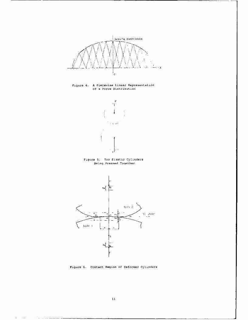
Figure 4. A Piecewise Linear Representationof a Force Distribution
/ I .... ,
Figure 5. Two Elastic Cylinders
Being Pressed Together
. ... -I__
Figure 6. Contact Region of Deformed Cylinders
11

C.,
I- - --+ + - V . .
Figure 7. Contact Region with Tangential Loading
slip regiu lr
hllf of cualitu. width froim nujiji ical Solui imixi ulrn iitrmil pressure rlin nuieical so .lion
iori i l pressure distribution
-Iiigrilild prcsu re distributioi((iir iII ,lor - ir *nlii',d h,- v ;irriws)
Figure 8. Contact Region Loading Distribution forContacting Steel/Aluminum Cylinders With Friction
12

P I
U.6
t hull of cunLact wVILh fam 11 i . Lzwa COLtO.
Q0, maximiTm normal pressure from llcrtziazi contactu Slidin tg ",.,t L c t
Heitzian contact
Figure 9. Comparison of Hertz and Numerical Solutionsfor Normal Pressure for Contacting/Sliding,
Steel/Aluminum Cylinders
evI !Lzia (-, uilLo..iAfv'L'ionol nurin~ti ctt(
04
H / u0 2 3
( I - -
0 0.2 . 1 .
T IiiiiiLl SIhI/LIL : LIt'SS
i-ntaxintilni norniil prfe..sur-e (IIerl.z)
h I..ilf of conLacl width (11-0.z)
Figure 10. Shear Stress Distributions
on the Steel Cylinder.
13

1!?rtziall conil.CICU2 fric Linal normul con LacL
0'l~0 SLI(1tli4g ('OLaLCC
I
Z. Lt
0 0.2 0.6 1 0 1 1
-T mnaximxumn shedr :Ares
P.2 maximum normal pressure (Ilertz)u.. half of contact width (llo:rtz)
Figure 11. Shear stress Distributions
on the Aluminum Cylinder
C2
Figure 12. Modeling Mating Gear Teeth as contacting Cylinders
14

NISA Report Documentation PageNational Aeronautics andSpace Administration
1. Report No. NASA TM -104?)7 2. Government Accession No. 3. Recipient's Catalog No.
AVSCOM TR 91-C-001; AIAA-91-2022 I4. Title and Subtitle 5. Report Date
Contact Stresses in Gear Teeth-A New Method of Analysis
6. Performing Organization Code
7. Author(s) 8. Performing Organization Report No.
Paisan Somprakit, Ronald L. Huston, and Fred B. Oswald E -6214
110. Work Unit No.9. Performing Organization Name and Address 505 -63-36
NASA Lewis Research Center 1L162211A47ACleveland, Ohio 44135 - 3191and 11. Contract or Grant No.
Propulsion DirectorateU.S. Army Aviation Systems CommandCleveland, Ohio 44135 - 3191 13. Type of Report and Period Covered
12. Sponsoring Agency Name and Address Technical MemorandumNational Aeronautics and Space AdministrationWashington, D.C. 20546 - 0001 14. Sponsoring Agency Code
andU.S. Army Aviation Systems CommandSt. Louis, Mo. 63120 - 1798
15. Supplementary Notes
Prepared for the 27th Joint Propulsion Conference cosponsored by AIAA, SAE, ASME, and ASEE, Sacramento,California, June 24-27, 1991. Paisan Somprakit and Ronald L. Huston, University of Cincinnati, Cincinnati, Ohio 45221;Fred B. Oswald, NASA Lewis Research Center. Responsible person, Fred B. Oswald, (216) 433-3957.
16. Abstract
This paper presents a new, innovative procedure called point load superposition for determining the contact stressesin mating gear teeth. It is believed that this procedure will greatly extend both the range of applicability and theaccuracy of gear contact stress analyses. Point load superposition is based upon fundamental solutions from thetheory of elasticity. It is an iterative numerical procedure which has distinct advantages over the classical Hertzmethod, the finite-element method (FEM), and over existing applications with the boundary element method(BEM). Specifically, friction and sliding effects, which are either excluded from or difficult to study with theclassical methods, are routinely handled with the new procedure. The paper presents the basic theory and algo-rithms. Several examples are presented. Results are consistent with those of the classical theories. Applicationswith spur gears are discussed.
17. Key Words (Suggested by Author(s)) 18. Distribution Statement
Contact stress Unclassified - UnlimitedGear teeth Subject Category 37GearsNumerical methods
19. Security Classif. (of the report) 20. Security Classif. (of this page) 21. No. of pages 22. Price .
Unclassified Unclassified 14 A03
NASA FORM 1626 OCT W For sale by the National Technical Information Service, Springfield, Virginia 22161