contact heat transfer - nanohub
TRANSCRIPT

Thermal Microsystems forThermal Microsystems forOnOn--Chip Thermal EngineeringChip Thermal Engineering
Suresh V. GarimellaPurdue University
March 21, 2006
Tel: (765) 494 5621 [email protected]
www.ecn.purdue.edu/CTRC

© Suresh Garimella
Motivation from MicroelectronicsMotivation from MicroelectronicsPackage (10Package (10--22))
Transistor (10Transistor (10--99 m)m)
Moore’s LawMoore’s Law
The Number of Transistors Per ChipWill Double Every 18 Months
The Number of Transistors Per ChipThe Number of Transistors Per ChipWill Double Every 18 MonthsWill Double Every 18 Months
1,000,0001,000,000
100,000100,000
10,00010,000
1,0001,000
1010
100100
11’75’75 ’80’80 ’85’85 ’90’90 ’95’95 ’00’00 ’05’05 ’10’10 ’15’15
1 Billion 1 Billion TransistorsTransistors
808680868028680286
i386™ Processori386™ Processori486™ Processori486™ Processor
PentiumPentium®® ProcessorProcessor PentiumPentium®® Pro ProcessorPro Processor
KK
Source: IntelSource: Intel
PentiumPentium®® II ProcessorII ProcessorPentiumPentium®® III ProcessorIII Processor
PentiumPentium®®4 Processor4 Processor
Thermal issues are a critical bottleneck to sustaining “Moore’s Law” through the next 3-5 decades, and hence to continued growth of this trillion-dollar market.
Silicon Die (10Silicon Die (10--22))Heat Sink (10Heat Sink (10--11))
System (10System (1000))Facility (10Facility (1022))

© Suresh Garimella
Need for Multidisciplinary ResearchNeed for Multidisciplinary ResearchDevices:
3D chip structures with integrated coolingOrganic and molecular devicesAtomistic models
Circuits:Active management of compute-intensive functionsEnergy-recovery and scavengingSub-threshold transistors
Materials:Nano-manufactured thermoelectricsNovel thermal materials (CNT-based, nanofins, nanofluids, …)
Thermals:On-chip microsystems-based coolingEmbedded microrefrigerators, ion-driven convection, field-emission cooling
Fabrication:Heterogeneous integration and packagingLow-loss quantum conductance channels synthesis

© Suresh Garimella
OnOn--Chip Thermal EngineeringChip Thermal Engineering
Address management of high thermal loads at three levelsSub-chip, chip, and system levelsHeat loads of 1000 W/cm2 at sub-chip/chip level5-10 kW/cm3 at system level
Integration of cooling approaches at all three levelsChip-integrated thermal sensing and control
Facilitate dynamic control of circuit architecture for thermal management
3D fabrication and integrationPolylithic wafer-scale heterogeneous hyper-integration

© Suresh Garimella
Thermal Management/Control StrategiesThermal Management/Control Strategies
++
+
+
+
+
+
++
+++
+
+
+
+
+
++
+
Thermoelectrics MicrochannelsNovel interface materials
Piezofans
Micropumps
Heat pipes
MIDAF
© Suresh Garimella
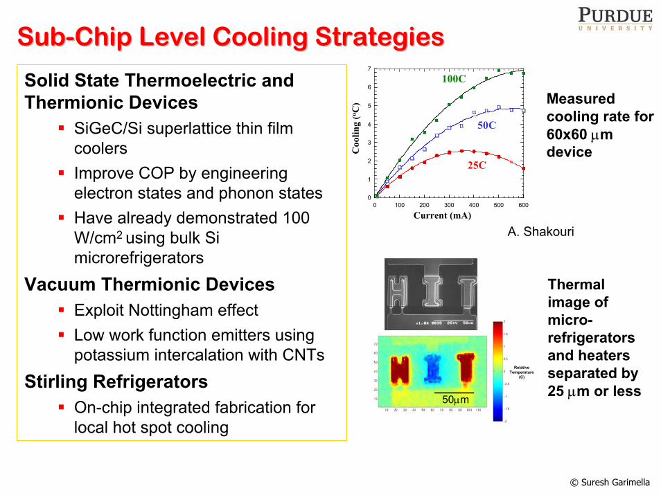
SubSub--Chip Level Cooling Strategies Chip Level Cooling Strategies
Coo
ling
(o C)
Current (mA)
25C
100C
0
1
2
3
4
5
6
7
0 100 200 300 400 500 600
50C
A. Shakouri
Solid State Thermoelectric and Thermionic Devices
SiGeC/Si superlattice thin film coolersImprove COP by engineering electron states and phonon statesHave already demonstrated 100 W/cm2 using bulk Si microrefrigerators
Vacuum Thermionic DevicesExploit Nottingham effectLow work function emitters using potassium intercalation with CNTs
Stirling RefrigeratorsOn-chip integrated fabrication for local hot spot cooling
Measured cooling rate for 60x60 µm device
Relative Temperature
(C)
50µm
Thermal image of micro-refrigerators and heaters separated by 25 µm or less

© Suresh Garimella
ChipChip--Level Cooling StrategiesLevel Cooling Strategies3D Integrated Ion Drag Devices
Electrons generated by emitters collide with air molecules creating ionsIons moved using traveling electric field40 W/cm2 heat removal possible
Micro-Thermosyphons and Heat Pipes
3D chip-integrated devices for conveying heat from interior of die stack to exterior
Microchannels and MicropumpsSingle and multiphase flow1000 W/cm2 possible
Electric Field and Ion Motion
Pumping Electrodes
Substrate
Ions Neutral Molecules
Ion drag device
SEM of polycrystalline diamond pyramid array (2.5 µm base, tip radium 5 nm)
T. Fisher

© Suresh Garimella
Thermal Interfaces Between LevelsThermal Interfaces Between Levels
0
50
100
150
200
250
300
350
400
450
0.1 0.2 0.3 0.4 0.5
Interface Pressure (MPa)
Ther
mal
Res
ista
nce
(Km
m2 /W
)
Bare Interface
CNT array (10 micron)
CNT array (25 micron)
Tw o-sided CNT array
ApproachDirect synthesis by plasma CVD of well-anchored carbon nanotube arrays over large areas on different substratesOptimize thermal conductance by varying nanotube density, diameter, alignment, and type
AdvantagesMinimum resistance to date ≈ 3 mm2K/W at moderate pressureDry, flexible interface reduces common interface material limitations, such as thermal stress fracture, dry out, pump out, etc.
T. Fisher
(top) SEM image of vertically aligned multi-walled carbon nanotube arrays used for thermal interface conduction. (bottom) Thermal interface resistance as a function of pressure between a silicon die and a copper rod.

© Suresh Garimella
Package and SystemPackage and System--Level StrategiesLevel Strategies
(a) t= 1/30
A
(b) t= 2/30 sec
B
A(c) t= 3/30 sec
A
B
(f) t= 10/30 (g) t= 13/30 s
(d) t= 5/30
A
B
At system level, we still need efficient spreading and cooling solutionsSubstantial research under NSF IUCRC
Miniature heat pipes and vapor chambersMicrochannels and micropumpsJet impingementPiezoelectric fans Solid/liquid phase-change solutionsMiniature vapor compression systems
sec
(e) t= 8/30 sA
B
C
D
sec
(h) t= 15/30
Flow visualization near a boundary, at different times; fan turned on at t = 0t = 0 s.

© Suresh Garimella
What are Thermal Microsystems?What are Thermal Microsystems?Encompass a broad range of microsystems with coupled electrical, thermal, mechanical, magnetic/optical/chemical/… interactions, in which:
Thermal means are used for direct electro-thermal actuation or operation
thermal bimorphsmicromotorsthermal inkjet printheadsmicro fuel injectors
Thermal phenomena are the functional basismicropumps, microvalveselectrowetting for surface tension controllab-on-chip systems
Thermal isolation/control is critical to operationon-chip thermal isolation of diode detectorshigh-performance thermal sensorsthermoelectric elements used for thermal sensing

© Suresh Garimella
Examples ofExamples of
Thermal MicrosystemsThermal Microsystems

© Suresh Garimella
Micromechanical EHD Micromechanical EHD MicropumpMicropumpNeed for:
Low-cost MEMS componentsLow-volume integrated micropumps
Considerations:Flow rateMaximum back pressureMiniaturizationSuitability for integration
Ahn
and
Alle
n (1
995)
Dew
a et
al.
(199
7)
Esas
hi e
t al.
(198
9)
Steh
r et a
l. (1
996)
Koch
et a
l. (1
998)
Kam
per e
t al.
(199
8)
Li e
t al.
(200
0)
Zeng
erle
et a
l. (1
995)
Böhm
et a
l. (1
999)
Xu
et a
l. (2
001)
Ols
son
et a
l. (1
997)
Bard
ell e
t al.
(199
7)
Scha
bmue
ller e
t al.
(200
0)
Ric
hter
et a
l. (1
991)
Fuhr
et a
l. (1
992)
Zeng
et a
l. (2
002)
Che
n et
al.
(200
0)
Lem
off a
nd L
ee (2
000)
Tsai
and
Lin
(200
1) Gen
g et
al.
(200
1)
Blac
k an
d W
hite
(199
9)
Weg
o an
d Pa
gel (
2001
)
Yun
et a
l. (2
001)
Gro
sjea
n an
d Ta
i (19
99)
0.1
1
10
100
1000
10000
Max
imum
flow
rate
/cro
ss-s
ectio
n ar
ea a
t zer
o ba
ck p
ress
ure,
µl
/min
.mm
2
Rotary ValvelessPiezoelectric BubbleElectroosmoticMHD
Elec
trost
atic
Elec
trom
agne
tic
Ther
mop
neum
atic
Sha p
e M
emor
y Al
loy
Peris
talti
c
EHD
(Inje
ctio
n)
EHD
(Ind
uctio
n)
Flex
ural
Plat
eW
aves
Elec
trow
ettin
g
Singhal, Garimella and Raman, Appl Mech Rev, 2004
Diffuser action
Nozzle action
Outlet Inlet
Diffuser action
Nozzle action
Outlet Inlet
Diffuser action
Nozzle action
Diffuser action
Nozzle action
Singhal, Garimella, Murthy, Sensors and Actuators, 2004Singhal, Garimella, IEEE Trans Adv Packaging, 2005
Nozzle Diffuser Micropumping

© Suresh Garimella
Novel MEMS Pump Feasibility AnalysisNovel MEMS Pump Feasibility Analysis
0.00E+00
5.00E-11
1.00E-10
1.50E-10
2.00E-10
0.00E+00 5.00E-04 1.00E-03 1.50E-03 2.00E-03Time (sec)
Q (m
3 /sec
)
Vibrating Diaphragm + Induction EHD
Induction EHD only
Piezoelectric Patch
Diaphragm
Channel54.7 deg
Piezoelectric Patch
Diaphragm
Channel54.7 deg
Cooling performanceSix 200 µm-wide microchannels in 2.25 mm2 chipTotal flow rate = 63 µl/minHeat removal rate = 87 mW for ∆T = 20°CPower input = 7 µW
Patent Pending

© Suresh Garimella
ChipChip--Integrated Integrated MicropumpMicropump DesignDesign
Diaphragm vibration
EHD

© Suresh Garimella
Modeling ResultsModeling Results
Electrodes
Diaphragm
200 µm

© Suresh Garimella
Device PrototypesDevice Prototypes
microchannels
mask
electrodes
bus bars

© Suresh Garimella
ChallengesChallenges
Integration into stacked structuresModeling of coupled effectsWafer bondingLiquid sealingIntegration-capable processes
Low temperatureCMOS compatible
Electrical insulationFor required EHD voltages
Material and process compatibilityReliability and low-cost manufacture
Electrode pattern
Bonded wafers (inverted orientation)

© Suresh Garimella
ElectrowettingElectrowetting for Actuation and Coolingfor Actuation and Cooling
Contact angle reduced on applying voltage (droplet wets surface)
Initial droplet shape
ElectrodeDielectric
Droplet
Contact angle decrease
V
Solid-liquid interface tension reduced by electric fieldDroplet spreads out and wets surfaceSurface tension gradient in droplet can lead to bulk motion of droplet

Continuous Droplet Movement Using EWContinuous Droplet Movement Using EW
Droplet
Top Plate
Bottom Plate
Filler Fluid
Actuation Electrodes
Ground Electrode
Dielectric Layer
Hydrophobic Layer
1 2 3
Continuous Droplet Movement

EWEW--Based Pumping/CoolingBased Pumping/Cooling
Droplets moving along an array of pulsed electrodes
Fluid sink
Fluid source
Heat sourceDroplet formation electrodes

© Suresh Garimella
Challenges for EWChallenges for EW--Based DevicesBased Devices
Understanding / modeling physics underlying electrical control of surface tension and the resultant droplet actuation Estimating dissipative mechanisms opposing droplet motion
Flow field in a moving droplet and resulting shear stressesDroplet contact angle hysteresisDroplet contact line friction
Mapping thermal performance of EW-based heat transfer devicesRole of surface effects on EW-based droplet transport
Surface roughness and morphologyInterface chemistry

© Suresh Garimella
Modeling EWModeling EW--Based Droplet FlowBased Droplet Flow
Energy minimization-based theory for droplet actuation force estimationGradient of system energy gives EW actuation force
( ) ( ) ( )2 2
2 21 02
1
62 2 2 2drop
D oil
vd x k Vm r x x C rdv r v rdt d d
µε ρ π ζ π= − − − −
Droplet
0 V
0 V V
x2 r
Dielectric C1
C2
C3
C4

© Suresh Garimella
Preliminary estimates show that heat transfer rates of 40 W/cm2
can be achieved with this approach, rivaling conventional liquid cooling approaches
Electron Emission& Ion Creation
Generating Region Pumping Region
Microchannels
Schlitz, Garimella, Fisher, ASME IMECE, 2004Zhang, Fisher, Garimella, J Appl Phys, 2004
MicroscaleMicroscale Ion Driven AirflowIon Driven Airflow
Darkfield image of single MWNT on W tip
Patent pending

© Suresh Garimella
MicroscaleMicroscale Ion Driven AirflowIon Driven Airflow
Ion and Air Flow
Electric Potential
Ion Cloud
Ion Cloud
Next Time Step
Initial Time Step
Electrodes
Φ (V)
x (m)
Φ (V)
x (m)
Ion and Air Flow
0.00E+00
2.00E-04
4.00E-04
6.00E-04
8.00E-04
1.00E-03
1.20E-03
0.0 1.0 2.0 3.0 4.0 5.0 6.0 7.0 8.0 9.0
x*
e*
t* = 0.0T*t* = 0.4T*t* = 0.8T*t* = 1.0T*
Periodic ion concentration
Peterson, Zhang, Fisher, Garimella, PSST, 2005
MIDAF over flat plate

© Suresh Garimella
Miniature Piezoelectric FansMiniature Piezoelectric Fans
Ultrasonic Piezoelectric Bimorph
Resonant vibration of small piezoelectric elements to generate air flow
Advantages of Piezoelectric Fans:Low power, 1-10 mWNoiseless for frequencies:
- Less than 100 Hz (infrasonic)- Greater than 20 kHz (ultrasonic)
Lightweight, compact and inexpensiveNo wearing parts, long life, robust and durableVersatile – configurable to different applications
slim profile fanbaffled infrasonic fans
Flow in an “impingement” mode
US Patent 6,713,942 B2

© Suresh Garimella
0 500 1000 150050
60
70
80
90
100
Time (sec)H
eatt
rans
ferc
oeffi
cien
th(W
/m2 K
)0 500 1000 1500
50
55
60
65
70
75
80
85
90
95
100
105
Vertical, Half CoverageVertical, Full CoverageVertical, No CoverageHorizontal
Enhancem
entin
h(%
)
102
64
52
28 Vertical Orientation
Horizontal Orientation
Heat Sink Piezoelectric Fan
Heat Transfer Feasibility
Infrasonic Fans Infrasonic Fans Feasibility and Feasibility and ModelingModeling
Açıkalın, Wait, Garimella, Raman, HTE, 2004
X (m)
Y(m
)
0.02 0.06 0.10
0.01
0.02
0.03
0.04
2-D streaming model for a
baffled piezoelectric
fan
Experimental flow visualization
agrees well with model
Açıkalın, Raman, Garimella, JASA, 2003
Analytical Finite element
Optimal thickness ratio:
tp/tb ≈ 0.5
Optimal length ratio:
(L2-L1)/L3 ≈ 0.6
Optimal geometry depends on material properties of the beam and the patch
Geometry Optimization
Buermann, Raman, Garimella, IEEE CPT 2002Basak, Raman, Garimella, J Vibr. Acous, 2005
Fluid Modeling

© Suresh Garimella
Ultrasonic Ultrasonic MicrofansMicrofans
At fixed field, a scaling down by a factor of 50 leads to a performance enhancement of a factor of 1000

© Suresh Garimella
HigherHigher--Mode Mode MicrocantileversMicrocantilevers
Macro fan in 5th Mode Micro fan in 1st Mode
Same frequency
Scale down all dimensions by 2 orders of magnitude
Fluid shear stresses concentrated near slots and outer edges
1Z R j Lj C
ωω
= + +
Power consumption and losses increase with mode number
Quality factors in air
Wait, Basak, Raman, Garimella, IEEE CPT, in reviewBasak, Raman, Garimella, JVA, 2005Basak, Raman, Garimella, J Appl Phys, 2006
ω↑ R↓ L↓↓ C↔ Z↓

© Suresh Garimella
Enabling TechnologiesEnabling Technologies
–– Fundamental Research Fundamental Research ––

© Suresh GarimellaLiu, Garimella, J Thermophys Heat Transfer, 2004Lee, Garimella, Liu, Int J Heat Mass Transfer, 2005
Velocity (m/s)
Rad
ialp
ositi
on(m
m)
0 0.1 0.2 0.3 0.4 0.5 0.6 0.7 0.8 0.9 1
0.05
0.1
0.15
0.2
0.25
0.3 IR PIV measurementTheory - Eq.(8)
ReN
u500
500
1000
1000
1500
1500
2000
2000
2500
2500
3000
3000
6 6
8 8
10 10
12 12
14 14
16 16
18 18
20 2022 2224 24
ExperimentTurbulentProposed correlation
SingleSingle--Phase Transport in Phase Transport in MicrochannelsMicrochannels
• Develop predictive relationships and correlations for single-phase flow
• Develop novel non-intrusive measurement techniques for MEMS devices

© Suresh Garimella
Bulk flow
G-10 housing
Copper block
Viewing window
O-ring groove
Thermocouple
Pressure transducer
MicrochannelThermocouple
Cartridge heater
Incipient heat flux q''exp (W/cm2)
Inci
pien
thea
tflu
xq'
' mod
el(W
/cm
2 )
10 20 30 40 50 6010
20
30
40
50
60
-20%
+20%
Time t (ms)B
ubbl
era
dius
r b(µ
m)
Con
tact
angl
eθ
(deg
)
0 100 200 300 4000
5
10
15
20
25
30
35
40
0
20
40
60
80
100
ONB
SlugAnnular
Heat flux q'' (W/cm2)
T w-T
in(o C
)
Wal
ltem
pera
ture
(o C)
10 20 30 40 50 60
6
8
10
12
14
16
18
20
22
0
0.2
0.4
0.6
0.8
1
Q = 0.16 LPM (Re = 610)Q = 0.20 LPM (Re = 763)Q = 0.23 LPM (Re = 877)
Wc = 275 umHc = 636 umDh = 384 umTin = 87 oC
Increasing flow velocity
Liu, Lee, Garimella, ASME JHT 2005Liu, Garimella, IJHMT 2005
Unresolved issuesFlow boiling mechanisms not fully identifiedFlow regime maps need to be constructed for the microscaleBoiling instabilities and associated flow mal-distribution not well predictedSingle-microchannel results not readily extrapolated to multiple microchannelsModels for flow boiling
TwoTwo--Phase Transport in Phase Transport in MicrochannelsMicrochannels
Liu, Lee, Garimella, IJHMT, 2005

© Suresh Garimella
Boiling VisualizationBoiling Visualization
Wc= 381 µm, Hc= 392 µmQ = 35 mL/min
12,500 fps
Pressure drop
Inlet and outlet Temperatures
Liquid inlet
Fluid outlet
Interface for wall temperature measurement and heat input
Heat sink
q” = 6.77 W/cm2 10.70
14.35 20.47
Re = 230 (liquid at inlet)

© Suresh Garimella
299.2299 .2
299.
2
300.
6
300.6
302.
0
302.0
303.
4
303.4
304.9
304.9
306.3
306.
3
306.3
307.7
307.7
309.1
309.
1
310.
5
x(m)
z(m
)
0 0.01 0.02 0.03 0.04 0.050
0.01
0.02
0.03
0.04 condensersection
5 mm
x (m)
Pre
ssur
edr
op(N
/m2 )
0 0.01 0.02 0.03 0.04 0.05-150
-100
-50
0
50
100
150
200
250
300
350
400
Vapor corethickness = 0.4 mmVapor corethickness = 0.8 mm
Vapor pressure drop
liquid pressure drop
∆
∆ Pv
Pl
HeaterClamp
Condensate CollectionAnnulus
Liquid Pool
WickConical
Cap
Thermocouple Pass-through
Vacuum Pressure
GageHeater
Clamp
Condensate CollectionAnnulus
Liquid Pool
WickConical
Cap
Thermocouple Pass-through
Vacuum Pressure
Gage
Miniature Flat Heat PipesMiniature Flat Heat Pipes
Transient analysis of miniature flat heat pipes at high heat fluxesPrediction of transient temperature, velocity and pressure fields in the heat pipePrediction of dryoutDissipation from multiple hot spotsPrediction of required wick propertiesWick performance and transport measurements
Vadakkan, Garimella, Murthy, JHT, 2004Iverson, Garimella, ASME HTFED, 2004

© Suresh Garimella
ThinThin--Film Evaporation: Film Evaporation: µµPIV Experiments PIV Experiments
CCD CAMERA
CENTER PLANE
TOP PLANE 2
BOTTOM PLANE 2
TOP PLANE 1
BOTTOM PLANE 1
gravity
x[pix]
y[pi
x]
100 200 300 400 500
100
200
300
400
500
600
x[pix]
y[pi
x]
100 200 300 400 500
100
200
300
400
500
600
x[pix]
y[pi
x]
100 200 300 400 500
100
200
300
400
500
600
x[pix]
y[pi
x]
100 200 300 400 500
100
200
300
400
500
600
x[pix]
y[pi
x]
100 200 300 400 500
100
200
300
400
500
600
Center planeTop Plane 1Top Plane 2 Bottom Plane 2Bottom Plane 1
Challenges:
• Moving meniscus• Particle agglomeration at
triple line
Microscale study of velocity field and evaporative mass flow near an evaporating meniscus
Test setup

© Suresh Garimella
Part II - intrinsic meniscusPart I - thin film
(invisible)
Junction Thickness δj
θ
Thin film
2000 W/m2
343 K Inlet
343K Vapor
1000 μm
100 μm
50 μmSteel
OctaneThin film: 0.35 WMeniscus: 4.25 W
Temperature Contour
ThinThin--Film Evaporation: ModelingFilm Evaporation: Modeling
• Analytical model for heat transfer from thin film region
• CFD model for intrinsic meniscus region
-13.0dC
0.0dC
-12
-10
-8
-6
-4
-2
0
LI01
dC
-8
-6
-4
-2
0 Temperature at back of foil along
LI01Microscale IR Temperature Microscale IR Temperature MeasurementsMeasurements
Thin film
Wire
Heated Foil

© Suresh Garimella
Enhanced Transport in OpenEnhanced Transport in Open--Cell FoamsCell Foams
Radius
Por
osity
0.48 0.49 0.5 0.51 0.520.85
0.87
0.89
0.91
0.93
0.95
0.97
0.99
AnalyticalFluent
R
2R
P orosity
Effe
ctiv
eTh
erm
alC
ondu
ctiv
ity,W
/mK
0.88 0.9 0.92 0.94 0.96 0.980
1
2
3
4
5
6
7
8
9
10
11
C almidi E xperimentsTetrakaidecahedron M odelBC C M odelBoomsma M odelC almidi M odelBhattacharya M odel
Aluminum - Air
Flow Direction
z
yx
_ =
Cube BCC Final Geometry
Constant Heat FluxKrishnan, Murthy, Garimella, ASME JHT, 2005Krishnan, Murthy, Garimella, ASME JHT, in press

© Suresh Garimella
Thermal Contact ConductanceThermal Contact Conductance
Insulated heat sink
Coolant Inlet
Coolant Outlet
Electrolytic iron flux meters
Experimental samples
Radiation shield(Front half removed to expose test column)
Insulated heat source
Direction of one-dimensional heat flux
Load Cell
Base Plate
Column Power Input Terminals
Column Support Bolts
Column Support Bolts
Hs
Hc
Hequiv
CNT TIM
0.00
2.00
4.00
6.00
8.00
10.00
12.00
14.00
16.00
18.00
20.00
0.00 1.00 2.00 3.00 4.00 5.00 6.00Interface Pressure (MPa)
TCC
(W/K
)
Experiment (Al 1 micron)Numerical Prediction BeforeNumerical Prediction After
Al-Al 1 µm Ra
T Fisher
Black, Singhal, Garimella, AIAA JTHT, 2004Black, Garimella, AIAA JTHT, 2005Singhal, Litke, Black, Garimella, IJHMT, 2005
Coated Joints
Experimental Test Column

© Suresh Garimella
MicrojetMicrojet ImpingementImpingement
Air Flow
(a) Ducted suction (bare)
H (19.5)
Cd (2.7)
Air Flow
(b) Ducted suction (enhanced)
H (21.9)
Cd (2.7)
C (3.18)
Air Flow
(a) Ducted suction (bare)
H (19.5)
Cd (2.7)
Air Flow
(b) Ducted suction (enhanced)
H (21.9)
Cd (2.7)
C (3.18)

© Suresh Garimella
MultiphysicsMultiphysics CoCo--Design ApproachDesign Approach
Quantum Dot
FET
Molecular Electronics
MicrochannelsMicroscale Ion Driven Convection
Thermoelectrics
Off-chip Interconnect & Stacked Die
Novel Materials, Devices and Circuit
Architectures
AMKORAMKOR
Integrated Pumps
ILLUSTRATION: C. SLAYDEN
CNT TIM
ICEICE333D IntegrallyCooledElectronics
Develop the fundamental science and technology needed for truly integrated electro-thermal co-design of thermal microsystems, with a focus on microelectronic systems

© Suresh Garimella
AcknowledgementsAcknowledgementsCTRC MembersCTRC Members
Aavid ThermalloyAlcoaAppleCisco SystemsDelphi Electronics and SafetyDensoEaton CorporationGeneral ElectricGraftechHoneywellIntel CorporationModine Manufacturing Co.NanoconductionNokia Research CenterPhilipsRockwell AutomationRockwell CollinsSandia National LabsSchlumbergerSony Computer EntertainmentSony CorporationSterling PCU
National Science FoundationNational Science FoundationSemiconductor Research CorpSemiconductor Research Corp2121stst Century R&T FundCentury R&T FundUS ArmyUS ArmyCray ResearchCray Research
Ph.D. StudentsPh.D. StudentsTolga AcikalinVaibhav BahadurSudipta BasakPramod ChamarthyDavid GoBrian IversonBen JonesMark KimberShankar KrishnanPoh-Seng LeeDong LiuAbhijit SatheDan SchlitzJames SimpsonVishal SinghalSuwat TrutassanawinUnni VadakkanWei Zhang
StaffStaffDr. Tailian ChenDr. Lorenzo CremaschiDr. Madhu IyengarDr. Dawei SunDr. Hao WangPhilip Buermann
M.S. StudentsM.S. StudentsRavi AnnapragadaTony BlackTyler DavisHemanth DhavaleswarapuPaul LitkeJohn McHaleChristine MerrillMike PetersonSydney Wait
FacultyFacultyTim FisherEckhard GrollJayathi MurthyArvind RamanSteve Wereley…

© Suresh Garimella
For more info For more info ……www.ecn.purdue.edu/CTRC

© Suresh Garimella
Questions and AnswersQuestions and Answers

© Suresh Garimella
Selected ReferencesSelected ReferencesS. V. Garimella and C. B. Sobhan, “Transport in Microchannels - A Critical Review,” Ann. Rev. Heat Transfer, 2003.C. B. Sobhan and S. V. Garimella, “A Comparative Analysis of Studies on Heat Transfer and Fluid Flow in Microchannels,” Microscale Thermophysical Engineering, Vol. 5, pp. 293-311, 2001.V. Singhal, S. V. Garimella, and A. Raman “Microscale Pumping Technologies for Microchannel Cooling Systems,”Applied Mechanics Reviews, Vol. 57, pp. 191-221, 2004.S. V. Garimella and V. Singhal, “Single-Phase Flow and Heat Transport and Pumping Considerations in Microchannel Heat Sinks,” Heat Transfer Engineering, Vol. 25, pp. 15-25, 2004.
S. V. Garimella, V. Singhal and D. Liu, “On-Chip Thermal Management with Microchannel Heat Sinks and Integrated Micropumps,” Procs IEEE (in press).D. Liu, P.S. Lee, and S. V. Garimella, “Prediction of the Onset of Nucleate Boiling in Microchannel Flow,”International Journal of Heat and Mass Transfer, Vol. 48, pp. 5134-5149, 2005.D. Liu, S. V. Garimella and S. T. Wereley, “Infrared Micro-Particle Image Velocimetry Measurement in Silicon-Based Microdevices,” Experiments in Fluids Vol. 38, pp. 385-392, 2005.D. Liu and S. V. Garimella, “Investigation of Liquid Flow in Microchannels,” AIAA J. Thermophysics and Heat Transfer, Vol. 18, pp 65-72, 2004.P.-S. Lee, S. V. Garimella, and D. Liu, “Investigation of Heat Transfer in Rectangular Microchannels,” International Journal of Heat and Mass Transfer, Vol. 48, pp. 1688-1704, 2005.
V. Singhal, S. V. Garimella and J. Y. Murthy, “Low Reynolds Number Flow Through Nozzle-Diffuser Elements in Valveless Micropumps,” Sensors and Actuators A, Vol. 113, pp. 226-235, 2004.V. Singhal and S. V. Garimella, “A Novel Valveless Micropump with Electrohydrodynamic Enhancement for High Heat Flux Cooling,” IEEE Transactions on Advanced Packaging, Vol. 28, 2005.
D. J. Schlitz, S. V. Garimella and T. S. Fisher, “Microscale Ion-Driven Air Flow over a Flat Plate,” Procs. HT-FED04, 2004 ASME Heat Transfer/Fluids Engineering Summer Conference, HT-FED04-56470, July 11-15, 2004, Charlotte, North Carolina.M. S. Peterson, W. Zhang, T. S. Fisher, and S. V. Garimella, “Low-Voltage Ionization of Air with Carbon-Based Materials,” Plasma Sources Science and Technology , Vol. 14, pp. 654-660, 2005.W. Zhang, T. S. Fisher and S. V. Garimella, “Simulation of Ion Generation and Breakdown in Atmospheric Air,”Journal of Applied Physics, Vol 96, No. 11, pp. 6066-6072, 2004.

© Suresh Garimella
Selected ReferencesSelected ReferencesT. Açıkalın, S. M. Wait, S. V. Garimella and A. Raman, “Experimental Investigation of the Thermal Performance of Piezoelectric Fans,” Heat Transfer Engineering, Vol. 25, pp. 4-14, 2004.T. Açıkalın, A. Raman and S. V. Garimella, “Two-dimensional Streaming Flows Induced by Resonating Thin Beams,” Journal of the Acoustical Society of America, Vol. 114, pp. 1785-1795, 2003.T. Acikalin, S. V. Garimella, J. Petroski and A. Raman, “Optimal Design of Miniature Piezoelectric Fans for Cooling Light Emitting Diodes,” ITHERM04, Las Vegas, Nevada, June 2004.S. Basak, A. Raman and S. V. Garimella, “Dynamic Response Optimization of PiezoelectricallyExcited Thin Resonant Beams,” ASME Journal of Vibration and Acoustics Vol. 127, pp. 18-27, 2005.
S. Krishnan, J. Y. Murthy and S. V. Garimella, “A Two-Temperature Model for Solid/Liquid Phase Change in Metal Foams,” ASME Journal of Heat Transfer Vol. 127, pp. 995-1004, 2005.S. Krishnan, S. V. Garimella, and S. S. Kang, “A Novel Hybrid Heat Sink using Phase Change Materials for Transient Thermal Management of Electronics,” IEEE Transactions on Components and Packaging Technologies Vol. 28, pp. 281-289, 2005.S. Krishnan and S. V. Garimella, “Analysis of a Phase Change Energy Storage System for Pulsed Power Dissipation,” IEEE Transactions on Components and Packaging Technologies,Vol. 27, pp 191-199, 2004.S. Krishnan and S. V. Garimella, “Thermal Management of Transient Power Spikes in Electronics - Phase Change Energy Storage or Copper Heat Sinks?” ASME Journal of Electronic Packaging, Vol. 126, pp. 308-316, 2004.S. Krishnan, J. Y. Murthy and S. V. Garimella, “A Two-Temperature Model for the Analysis of Passive Thermal Control Systems,” ASME Journal of Heat Transfer, Vol. 126, pp. 628-637, 2004.

© Suresh Garimella
Selected ReferencesSelected ReferencesS. V. Garimella and C. B. Sobhan, “Recent Advances in the Modeling and Applications of Nonconventional Heat Pipes,” Chapter 4, Advances in Heat Transfer, Vol. 35, pp. 249-308, 2001.U. Vadakkan, J. Y. Murthy and S. V. Garimella, “Transient Analysis of Flat Heat Pipes,” ASME Summer Heat Transfer Conference, Las Vegas, Nevada, HT2003-47349, July 21-23, 2003.U. Vadakkan, S. V. Garimella and J. Y. Murthy, “Transport in Flat Heat Pipes at High Heat Fluxes from Multiple Discrete Heat Sources,” ASME Journal of Heat Transfer, Vol. 126, pp. 347-354, 2004B. D. Iverson and S. V. Garimella, “Experimental Measurements of Heat and Mass Transport in Heat Pipe Wicks,” Procs. HT-FED04, 2004 ASME Heat Transfer/Fluids Engineering Summer Conference, HT-FED04-56230, July 11-15, 2004, Charlotte, North Carolina.
V. Singhal, P. J. Litke, A. F. Black and S. V. Garimella, “An Experimentally Validated Thermomechanical Model for the Prediction of Thermal Contact Conductance,” International Journal of Heat and Mass Transfer Vol. 48, pp. 5446-5459, 2005.A. F. Black, V. Singhal and S. V. Garimella, “Analytical Investigation and Predictive Correlation for Constriction Resistance,” AIAA Journal of Thermophysics and Heat Transfer, Vol. 18, pp. 30-36, 2004.V. Singhal, T. Siegmund and S. V. Garimella, “Optimization of Thermal Interface Materials for Electronics Cooling Applications,” IEEE Transactions on Components and Packaging Technologies, Vol. 27, June 2004.C. V. Madhusudana and S. V. Garimella, “Measurement of Thermal Contact Conductance –Steady-State or Transient?” Paper Number TED-AJ03-179, Procs. 6th ASME-JSME Thermal Engineering Joint Conference, Kohala Coast, Hawaii, March 16-20, 2003