consultation paper: consp:10 - bre · 2.1 testing of mvhr products in sap 2012 at present, the sap...
TRANSCRIPT
SAP SUPPORTING DOCUMENT
This document is the property of the Building Research Establishment Ltd (BRE), who are contracted to maintain and develop the National Calculation Methodologies for Energy Rating of Dwellings (SAP/RdSAP)
on behalf of the Department of Energy and Climate Change (DECC)
Consultation Paper: CONSP:10
Changes to Mechanical Ventilation System assumptions in SAP 2016
Issue 1.0
Issue: 1.0 Changes to Mechanical Ventilation System assumptions in SAP 2016
CONSP:14
Date: 28/06/2016 Page 2 of 22
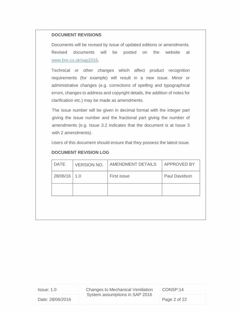
DOCUMENT REVISIONS
Documents will be revised by issue of updated editions or amendments.
Revised documents will be posted on the website at
www.bre.co.uk/sap2016.
Technical or other changes which affect product recognition
requirements (for example) will result in a new issue. Minor or
administrative changes (e.g. corrections of spelling and typographical
errors, changes to address and copyright details, the addition of notes for
clarification etc.) may be made as amendments.
The issue number will be given in decimal format with the integer part
giving the issue number and the fractional part giving the number of
amendments (e.g. Issue 3.2 indicates that the document is at Issue 3
with 2 amendments).
Users of this document should ensure that they possess the latest issue.
DOCUMENT REVISION LOG
DATE VERSION NO. AMENDMENT DETAILS APPROVED BY
28/06/16 1.0 First issue Paul Davidson

Issue: 1.0 Changes to Mechanical Ventilation System assumptions in SAP 2016
CONSP:14
Date: 28/06/2016 Page 3 of 22
TABLE OF CONTENTS
1. Introduction ........................................................................................................ 4
2. Part 1: MVHR duct insulation and location ......................................................... 5
2.1 Testing of MVHR products in SAP 2012 ................................................... 5
2.2 Shortcomings of present assumptions ...................................................... 6
2.3 Impact of shortcomings ............................................................................ 7
2.4 PROPOSED CHANGES FOR SAP 2016 ................................................. 8
2.5 Impact of proposed changes .................................................................... 9
2.6 Summary of proposed changes ................................................................ 9
3. Part 2: MVHR aerodynamic performance data ................................................ 11
3.1 Testing of MVHR products in SAP 2012 ................................................. 11
3.2 Shortcomings of the current test methodology ........................................ 12
3.3 Impact of shortcomings .......................................................................... 14
3.4 PROPOSED CHANGES FOR SAP 2016 ............................................... 14
3.5 Impact of proposed changes .................................................................. 15
3.6 Summary of proposed changes .............................................................. 16
4. Part 3: Decentralised MEV performance .......................................................... 17
4.1 Decentralised mechanical extract ventilation .......................................... 17
4.2 SAP test method for dMEV products ...................................................... 17
4.3 Shortcomings of the current method ....................................................... 18
4.4 Impact of shortcomings .......................................................................... 19
4.5 PROPOSED CHANGES FOR SAP 2016 ............................................... 20
4.6 Impact of proposed changes .................................................................. 21
4.7 Summary of proposed changes .............................................................. 22

Issue: 1.0 Changes to Mechanical Ventilation System assumptions in SAP 2016
CONSP:14
Date: 28/06/2016 Page 4 of 22
1. Introduction
Dwellings have become more airtight in recent years to meet increasingly demanding
regulations requiring reduced energy use. As a result, ventilation provision has tended to
change:
- from intermittent extract fans with background ventilation achieved through
naturally driven air flows
- to continuously operated mechanical ventilation systems; sometimes these are
extract-only and sometimes balanced systems with heat recovery
This paper discusses a number of proposed improvements to the way that SAP evaluates
the performance of mechanical ventilation systems and is in three parts.
Part 1 deals with the thermal performance of Mechanical Ventilation and Heat Recovery
(MVHR) units, relating to the effects of duct insulation and of being installed inside or
outside the building thermal envelope.
Part 2 deals with the test methods and handling of aerodynamic performance data for
MVHR units in relation to SAP.
Part 3 deals with the test methods and handling of aerodynamic performance data for
decentralised mechanical ventilation (dMEV) in relation to SAP.
Improvements are proposed relating to each of these areas for SAP 2016, together with
ways of making test data and SAP results more representative of actual installations.
Issue: 1.0 Changes to Mechanical Ventilation System assumptions in SAP 2016
CONSP:14
Date: 28/06/2016 Page 5 of 22
2. Part 1: MVHR duct insulation and location
2.1 Testing of MVHR products in SAP 2012
At present, the SAP test method assesses the thermal performance of an MVHR product
based on the test method defined in EN13141-7:20041, which in turn is based on the test
method defined in EN308:19972.
The required ambient laboratory temperature and extract and fresh air temperatures were
changed in EN13141-7:20103. Following a review of the impact of this change, it was
decided that the older temperature test points should be retained for consistency and to
maintain the current level of resolution resulting from the large overall temperature
difference.
For entry in the Product Characteristics Database (PCDB), the thermal efficiency of an
MVHR unit is tested at each air flow rate used to determine specific fan power, i.e. a flow
rate equivalent to a kitchen plus a given number of wet rooms. A good indication of the
thermal performance of the product is gained in this way. However, EN308 requires that
the temperature of the air in each duct is measured as close as possible to the product
spigots to minimise errors. This ensures that the measured efficiency relates to the MVHR
only and does not reflect overall system effects.
1 EN13141-7:2004. Ventilation for buildings — Performance testing of components/products for residential ventilation. Part 7: Performance testing of a mechanical supply and exhaust ventilation units (including heat recovery) for mechanical ventilation systems intended for single family dwelling 2 EN308:1997. Heat exchangers - Test procedures for establishing the performance of air to air and flue gases heat recovery devices 3 EN13141-7:2010. Ventilation for buildings — Performance testing of components/products for residential ventilation. Part 7: Performance testing of a mechanical supply and exhaust ventilation units (including heat recovery) for mechanical ventilation systems intended for single family dwelling

Issue: 1.0 Changes to Mechanical Ventilation System assumptions in SAP 2016
CONSP:14
Date: 28/06/2016 Page 6 of 22
EN308:1997 allowed the laboratory temperature to range from 17 to 27°C. This tolerance
was tightened in EN13141-7:2010 to ±1°C of the extract air temperature, i.e. 20±1°C. The
SAP test methodology4 requires the laboratory to be held at these conditions.
2.2 Shortcomings of present assumptions
BRE has undertaken a number of field measurements of MVHR installations and has
measured system thermal efficiencies5 as low as 50% when installed outside the heated
envelope6. In these cases the laboratory thermal efficiency was typically 90%. This
difference results from a combination of the heat lost from the MVHR unit and the lack of
effective duct thermal insulation within the cold space. Duct heat losses vary with respect
to the length of duct located in the cold space, which in some dwellings is very significant.
The widespread practice of installing MVHRs outside the thermal envelope of a dwelling
means that the ambient air temperature around the MVHR during the period of the year
when it is actively recovering heat is not the same as that within the test laboratory when
the thermal efficiency was measured. When installed in lofts, due to the high levels of
insulation in modern houses, the air temperature may be close to outside air temperature.
Whether in a well-insulated loft or outside the dwelling, this means that during most of the
heating season the ambient temperature of the MVHR and the ductwork is significantly
below 20°C.
In cases where the MVHR unit is located within the thermal envelope of the dwelling, the
ducts from the outside to the MVHR are inside the building. Both the fresh air duct and
exhaust air duct are potentially very cold. If inadequately insulated, the heat transfer from
the dwelling to the air in these ducts will be significant. Additionally, the increased air
temperature within the fresh air duct will reduce the heat exchanger temperature
4 TESTM-01 - SAP 2012 - Test method for centralised mechanical supply and extract ventilation
system packages with heat recovery used in a single dwelling
5 This is the heat returned to a dwelling, compared to that removed from a dwelling, both at the
thermal envelope boundary.
6 Refer to NHBC Foundation document: NF52 - “Assessment of MVHR systems and air quality in
zero carbon homes”

Issue: 1.0 Changes to Mechanical Ventilation System assumptions in SAP 2016
CONSP:14
Date: 28/06/2016 Page 7 of 22
difference and thus the heat recovery potential. For the exhaust air duct, the heat transfer
results in a direct heat loss from the dwelling to the outside air. It is vital therefore that both
ducts are kept to a minimum length and insulated effectively.
With MVHR thermal efficiencies typically measured at 90% in the laboratory, the need for
high levels of thermal insulation to reduce heat losses is critical. The Domestic Ventilation
Compliance Guide – 2010 Edition states in Table 7 that ductwork; should be insulated
where it passes through unheated areas and voids with the equivalent of at least 25 mm
of a material having a thermal conductivity if ≤0.04W/(m.K) to reduce the possibility of
condensation forming.
BRE staff have frequently observed installations with very limited insulation, in some cases
a single wrap of foil backed bubble wrap. Where insulation levels are poor, in cold weather
the low efficiency may result in cold air being delivered to rooms (living rooms and
bedrooms), causing discomfort.
The current ‘in-use’ factors were determined in a laboratory, based on a combination of
air flow imbalance, resulting in an imbalance in the overall heat recovery, and the heat
losses from the MVHR and ducts. The losses from the duct, however, assumed that the
duct lengths were minimised and the ducts insulated with appropriate levels of insulation.
The ‘in-use’ factor applied to the thermal efficiency is set at 0.85 for insulated and 0.70 for
uninsulated ducts. These have not been changed in SAP 2009 and 2012, since their
introduction in SAP 2005.
2.3 Impact of shortcomings
Where MVHRs are located outside the thermal envelope:
- MVHR system designers are not actively considering the impact on the overall
thermal efficiency of the system if the MVHR itself is located outside the
thermal envelope. Therefore, where cold lofts are available this space is seen
as appropriate for locating the MVHR and a significant amount of the room
supply and extract ducts (and all external supply and discharge ducts).

Issue: 1.0 Changes to Mechanical Ventilation System assumptions in SAP 2016
CONSP:14
Date: 28/06/2016 Page 8 of 22
- Where MVHRs units are located in cold lofts, system designers are not
specifying the correct level of insulation for room supply and extract ducts.
Both of the above shortcomings result in very significant levels of heat loss and thus the
thermal efficiency of the system during the heating season is significantly lower than is
assumed in SAP. Additionally, where MVHRs are located within the heated envelope:
- The level of insulation applied to the cold (fresh air intake and exhaust) ducts
is frequently not of the appropriate level. This leads to increased heat loss and
in many cases condensation and mould growth on the ducts.
The use of fixed ‘in-use’ factors means that there is no design incentive to install the MVHR
within the heated envelope, or to apply appropriate levels of duct insulation. The current
‘in-use’ factors are therefore failing to discourage poor design practice and this must be
rectified.
2.4 PROPOSED CHANGES FOR SAP 2016
The location of the MVHR is the simplest indication as to whether the heat losses are
going to be greater than assumed in the SAP testing. If the MVHR is located outside the
thermal envelope, it is proposed that the ‘in-use’ factor is revised to reflect the likely losses
that will occur from the MVHR and ductwork.
For MVHRs located outside the thermal envelope of the dwelling:
This may be in the loft or outside the dwelling.
If the ducts are insulated to 25mm minimum depth7
- the proposed ‘in-use’ factor is 0.5.
7 Continuously insulated and with thermal conductivity 0.04 W/(m.K) or less, as required by the
Domestic Ventilation Compliance Guide.

Issue: 1.0 Changes to Mechanical Ventilation System assumptions in SAP 2016
CONSP:14
Date: 28/06/2016 Page 9 of 22
If the ducts are not insulated to this depth
- the proposed ‘in-use’ factor is 0.25.
For MVHRs located inside the thermal envelope of the dwelling:
If the duct length from outside to the MVHR is over 2 m then the minimum insulation level
needs to be better than 25mm; it is proposed that a minimum of 50 mm insulation depth
should be incentivised by the ‘in-use factors’.
Proposed minimum insulation depths are therefore:
- 25mm for ducts less than 2m
- 50mm for ducts greater than 2m
If the insulation depth:
- Satisfies this minimum level, the ‘in-use’ factor is 0.9
- Does not satisfy this minimum or is unknown, the ‘in-use’ factor is 0.8
For future revisions to the Domestic Ventilation Compliance Guide, it is suggested that a
vapour impermeable insulation layer is required; if cold ducts are installed within the
dwelling internal environment, condensation will form on the ducts and the use of mineral
fibre insulation without vapour sealing will be less effective.
2.5 Impact of proposed changes
The purpose of the proposed changes is to improve the accuracy and robustness of SAP
assessments. It is anticipated that the proposed changes will also encourage improved
design practice.
2.6 Summary of proposed changes
MVHRs are tested for entry on the PCDB with a test laboratory temperature of 20±1°C;
this does not account for any heat losses from connected ducts. It is common practice to
place the MVHR in an unheated space along with a significant amount of distribution
Issue: 1.0 Changes to Mechanical Ventilation System assumptions in SAP 2016
CONSP:14
Date: 28/06/2016 Page 10 of 22
ductwork. Reviewing many installations during field inspections8 has also confirmed that
inadequate levels of duct thermal insulation are commonplace.
It is proposed that the ‘in-use’ factors in SAP 2016 are modified to better reflect the impact
of locating the MVHR and associated ductwork in an unheated space and the effect of
poor insulation of ducts. The overall effects of these changes will be to improve the
accuracy of SAP and reflect good design and specification of both the MVHR installation
and insulation of ducts.
8 Anonymous installation sites inspected during BRE site investigations. These include sites
inspected as a joint commission by the BRE Trust and Joseph Rowntree Foundation – report not
yet published.

Issue: 1.0 Changes to Mechanical Ventilation System assumptions in SAP 2016
CONSP:14
Date: 28/06/2016 Page 11 of 22
3. Part 2: MVHR aerodynamic performance data
3.1 Testing of MVHR products in SAP 2012
Testing mechanical ventilation products to the relevant EN test standards4 produces a set
of fan curves showing fan static pressure against air flow rate. While this data is useful if
a full and detailed design of a system is being undertaken, determining the design point
based on the fan curve requires a very detailed understanding of the duct distribution
system installed. This level of data is not usually available to SAP assessors or Building
Control when assessing systems installed in dwellings. A test method was therefore
developed for SAP that allowed the determination of performance of mechanical
ventilation products against a defined system and at defined air flow rates 4.
The system chosen as being typical in UK dwellings was based on a layout presented in
EN13141-6:20049, with rectangular 220 x 54 mm plastic duct chosen as typical of the vast
majority of MVHR installations, The methodology was agreed with mechanical ventilation
trade associations (BEAMA and FETA) before implementation.
The test methodology air flow rates were updated in SAP 2012, increasing from a
maximum 51 l/s to 69 l/s. Total test duct system pressures at the new air flow rates are
approximately 200 Pa on the supply side and 270 Pa on the extract side.
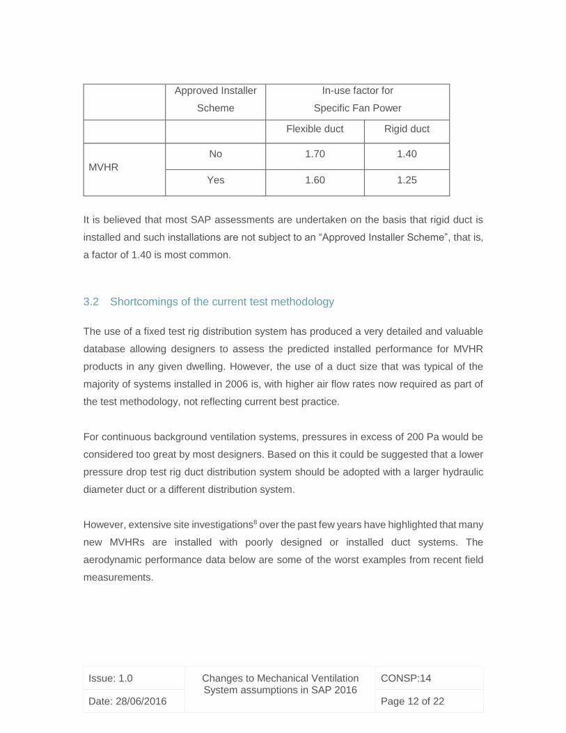
Within the SAP calculation, in-use factors are applied to Specific Fan Power (SFP) test
measurement values. These are recorded in the PCDB and are:
9 EN13141-6:2004. Ventilation for buildings — Performance testing of components/products for residential ventilation. Part 6: Exhaust ventilation system packages used in a single dwelling
Issue: 1.0 Changes to Mechanical Ventilation System assumptions in SAP 2016
CONSP:14
Date: 28/06/2016 Page 12 of 22
Approved Installer
Scheme
In-use factor for
Specific Fan Power
Flexible duct Rigid duct
MVHR
No 1.70 1.40
Yes 1.60 1.25
It is believed that most SAP assessments are undertaken on the basis that rigid duct is
installed and such installations are not subject to an “Approved Installer Scheme”, that is,
a factor of 1.40 is most common.
3.2 Shortcomings of the current test methodology
The use of a fixed test rig distribution system has produced a very detailed and valuable
database allowing designers to assess the predicted installed performance for MVHR
products in any given dwelling. However, the use of a duct size that was typical of the
majority of systems installed in 2006 is, with higher air flow rates now required as part of
the test methodology, not reflecting current best practice.
For continuous background ventilation systems, pressures in excess of 200 Pa would be
considered too great by most designers. Based on this it could be suggested that a lower
pressure drop test rig duct distribution system should be adopted with a larger hydraulic
diameter duct or a different distribution system.
However, extensive site investigations8 over the past few years have highlighted that many
new MVHRs are installed with poorly designed or installed duct systems. The
aerodynamic performance data below are some of the worst examples from recent field
measurements.

Issue: 1.0 Changes to Mechanical Ventilation System assumptions in SAP 2016
CONSP:14
Date: 28/06/2016 Page 13 of 22
MVHR
Air flow
rate
l/s
System pressure Specific Fan Power
Approx
date of
install
SAP test
Pa
Site measured
Pa
SAP test
W/(l/s)
Site measured
W/(l/s)
Product
X10 54 150 280 0.80 1.72 2013
Product
Y11 27 55 85 0.69 1.44 2012
Product
Z12 27 55 270 0.93 2.70 2013
The reasons for the significant differences between the tested and measured values
following re-commissioning of the systems to the design air flow rates were:
Undersized ducts for air flow rate.
Excessively long runs and number of bends in primary duct.
Incorrectly sized roof mounted inlet/exhaust terminal.
In many of the recently investigated cases the design and specification of the duct
distribution system has been poor, with installation quality being reasonable and largely in
accordance with the design. It is commonly perceived that poor performance has been
due to installation quality, but in the observed cases poor system design is more prevalent.
10 Measurements commissioned by householder; report unpublished. Measurements undertaken
by BRE technician in accordance (as far as practicable) with: “SAP 2012 - Test method for
centralised Mechanical Ventilation and Heat Recovery (MVHR) system packages”
11 Measurements commissioned by BRE Trust and Joseph Rowntree Foundation on a range of
installation sites; report not yet published. Measurements undertaken by BRE technician in
accordance (as far as practicable) with: “SAP 2012 - Test method for centralised Mechanical
Ventilation and Heat Recovery (MVHR) system packages”
12 Measurements commissioned by five householders for each of their dwellings, with similar results
for dwelling – the quoted value is worst case; report unpublished. Measurements undertaken by
BRE technician in accordance (as far as practicable) with: “SAP 2012 - Test method for centralised
Mechanical Ventilation and Heat Recovery (MVHR) system packages”

Issue: 1.0 Changes to Mechanical Ventilation System assumptions in SAP 2016
CONSP:14
Date: 28/06/2016 Page 14 of 22
3.3 Impact of shortcomings
There are two impacts resulting from the shortcomings identified above:
- MVHR system designers are not taking the aerodynamic performance of the
duct distribution system into account sufficiently when designing the system
and specifying the components. This is resulting in systems that have
significantly higher SFP13 values than is utilised in SAP calculations.
- Where systems are designed well, and/or use an innovative low pressure drop
duct system, such as semi-rigid duct, the SFP values utilised in SAP are
excessively high and are not rewarding good design and system specification
practice which result in lower energy use.
3.4 PROPOSED CHANGES FOR SAP 2016
Changing the duct layout to reflect the use of larger ducts for larger systems would allow
better design and specification practice to be rewarded, but would result in making
comparison of new to existing products difficult. It is therefore proposed that the test duct
configuration, which represents a “challenging” configuration, is not changed.
The impact of poor design could be captured through on-site measurement of all systems.
It is suggested that this would be difficult to achieve reliably and the resulting poor on-site
measurement may only result in the performance gap increasing.
Current test duct configuration does not significantly differ aerodynamically from many
installations and only in some cases is the design of the system such that the overall
installed aerodynamic performance is worse than that of the test. The combination of the
existing test configuration and current SAP in-use factor of 1.4 is capturing all but the worst
installations.
13 Specific Fan Power – electrical power (W) / air circulated through the fan (l/s)
Issue: 1.0 Changes to Mechanical Ventilation System assumptions in SAP 2016
CONSP:14
Date: 28/06/2016 Page 15 of 22
However, it is believed that SAP’s inability to recognise good design and specification of
MVHR systems is resulting in poor design becoming commonplace, with the poor
performance of systems then being unfairly assigned to the quality of the installation. To
act as an incentive to eliminate this,
- it is proposed that the actual installed performance of the system could
be measured and this data used directly in SAP. This would be an
optional input that could be used to recognise good system design, or
use of a low pressure duct distribution system.
The parameters that must be measured to enable an audit of the measurements to be
made both at a desk top and on-site level are:
MVHR fan speed settings at continuous background setting.
Total air flow rate at continuous background setting, supply and extract.
Electrical power drawn when the system is at continuous background setting.
Pressure difference across the MVHR on the supply and extract sides of the unit
at continuous background setting.
Whilst accurately measuring pressure difference will be more challenging, it is considered
practicable to obtain the above measurements given the development in available
measurement tools and because this would act as an extension to the existing airflow
measurement requirements defined in the Domestic Ventilation Compliance Guide (2010
Edition). Additionally, due to available PCDB data, the risk of measurement result
fabrication is considered to be minimised.
- It is proposed that the ‘in-use’ factor for the SFP derived from on-site
measured data should be 1.10
3.5 Impact of proposed changes
The key aim of these revisions is to promote and reward better design practice for MVHR
systems. If the electrical power drawn is minimised through good duct distribution system
design and component specification, followed by careful installation, then the gap between
design and in-use performance will be minimised.

Issue: 1.0 Changes to Mechanical Ventilation System assumptions in SAP 2016
CONSP:14
Date: 28/06/2016 Page 16 of 22
3.6 Summary of proposed changes
MVHRs are currently listed on the PCDB based on test data, with a pre-defined duct
configuration for a range of dwelling sizes. The test is now considered pessimistic because
the duct sizes and layout do not follow current best practice. However, on-site
investigations have revealed many cases where the duct distribution design is resulting in
significantly poorer performance.
For SAP 2016 it is proposed that this test is not updated to reflect what would be
considered as current best practice, since this would tend to reward all systems regardless
of design. Instead, for systems designed well or using an innovative low pressure duct
distribution system, it is proposed that aerodynamic performance should be determined
through measurement and an improved SAP in-use factor applied. This will improve the
accuracy of SAP and provide a significant incentive to encourage best practice design and
installation quality. The Domestic Ventilation Compliance Guide – 2010 Edition (and 2011
amended version) includes a requirement and format for reporting air flow site
measurements; the proposals form an extension of these requirements. A suitable
commissioning certificate will be required for handover to the SAP assessor.

Issue: 1.0 Changes to Mechanical Ventilation System assumptions in SAP 2016
CONSP:14
Date: 28/06/2016 Page 17 of 22
4. Part 3: Decentralised MEV performance
4.1 Decentralised mechanical extract ventilation
Continuously operating mechanical extract systems entered in the PCDB were all initially
central fans with the extract air being ducted from the various rooms to the fan and then
exhausted outside. In 2007, following problems with duct installation quality and a desire
to remove the need for ducting within the dwelling as far as possible, decentralised
continuous mechanical extract ventilation (dMEV) systems were developed and were
defined as a category of mechanical ventilation system within SAP. A test method14 was
developed that allowed the performance to be assessed against a range of representative
installation configurations.
4.2 SAP test method for dMEV products
At present, the SAP test method (all versions) assesses the aerodynamic performance of
a dMEV fan at two fixed air flow rates. These were based on typical air flow rates required
in kitchens and other wet rooms. Three installation configurations were used:
1. Through the wall: The fan mounted on a wall and exhausting direct to
outside.
2. In room: The fan mounted on a wall or ceiling within a room and exhausting
direct to outside via a defined duct.
3. In duct: The fan mounted within the duct and exhausting direct to outside
via a defined duct.
The results of the three tests are entered in the PCDB and a SAP assessor uses the
specific fan power (SFP) data appropriate to the installation configuration.
14 SAP PCDB: Test method for decentralised exhaust ventilation system packages used in a single
dwelling

Issue: 1.0 Changes to Mechanical Ventilation System assumptions in SAP 2016
CONSP:14
Date: 28/06/2016 Page 18 of 22
4.3 Shortcomings of the current method
Manufacturers of dMEV products have been found to ‘tune’ their products15 for optimal
performance at the two SAP specified test air flow rates, whilst also satisfying the wind
backpressure test. Unfortunately, this has led to a range of shortfalls in overall
performance:
4.3.1 Performance variations at flow rates below those tested
It has become evident that the aerodynamic performance of many of these products is
significantly different when the air flow rate is reduced below that of the SAP test method.
For some dMEV products entered in the PCDB, fan curves supplied within marketing
literature indicate that the performance drop below the lower air flow rate test point is so
significant that the fan could not pass the functional wind backpressure test.
To overcome this lack of aerodynamic performance at low air flow rates, many dMEV
products have a constant volume function integrated into the fan speed control. This
detects when the air flow rate reduces due to a small increase in back pressure. Some
products have this function enabled at all fan speeds, while others have been found to
enable it only at the test air flow rates. The effect of this is that at air flow rates below the
lower flow rate tested, the fan does not respond to any increase in back pressure and the
flow rate, and therefore efficacy, falls very quickly.
4.3.2 Limited flow rate options
A related problem is that dMEV products are being offered to the market with only two
defined trickle ventilation air flow rate settings and a boost setting, i.e. the air flow rates
required for satisfying the SAP test method14 plus a boost. This will inevitably mean that
the background air flow rate required by the Building Regulations and assumed to be
satisfied in SAP may not be achieved.
15 Based on unpublished technical audit testing of a wide selection of product samples that was
undertaken in support of maintaining the Product Characteristics Database

Issue: 1.0 Changes to Mechanical Ventilation System assumptions in SAP 2016
CONSP:14
Date: 28/06/2016 Page 19 of 22
4.3.3 Duct runs significantly longer than those of the test method
The duct run defined in the test methodology for testing dMEV products assumes a
relatively short overall distance between the extract terminal and the exhaust terminal.
Assessment of the actual installed configuration has frequently revealed that much greater
duct lengths are being installed and a significantly greater number of bends are present.
Reviewing the aerodynamic performance of many of the fans that have come to market in
the past few years leads to the conclusion that fan power would have to be significantly
increased above that measured during the performance test to achieve the correct air flow
rate.
4.3.4 Vents closed
As noted above, the performance of many dMEV products can be significantly influenced
by variations in backpressure. There is some evidence that the use of very low powered
fans and the ability to close trickle vents is resulting in under-ventilation of some rooms.
It is unlikely that this is occurring due to a reduction of overall air flow rate through the fan,
unless the levels of air tightness achieved in the construction is very high, but it may mean
that the assumed air flow path through a dwelling (e.g. through the trickle vents in the
living rooms, through the circulation spaces and into the wet rooms) is not occurring and
some living rooms, where vents are closed, are significantly under-ventilated.
4.4 Impact of shortcomings
There are two impacts resulting from the shortcomings identified above:
- The installed power drawn by the fans may be significantly greater than that
measured during the test, which implies that the SAP PCDB record will be
incorrect.
- The effectiveness of this technology to adequately ventilate dwellings may, in
some cases, be significantly below that required, resulting in potential under-
ventilation in the whole or areas of a dwelling.

Issue: 1.0 Changes to Mechanical Ventilation System assumptions in SAP 2016
CONSP:14
Date: 28/06/2016 Page 20 of 22
4.5 PROPOSED CHANGES FOR SAP 2016
Removing this mechanical ventilation category from SAP and returning to a significantly
increased default value for all products would address the gap between power actually
used and the test assessment. However, this would not increase the effectiveness of this
product category, and the removal of any testing may even result in a lowering of the
overall performance of products. This option is therefore not considered as appropriate.
.
4.5.1 Increase the size of the test installation configuration
The current test duct lengths are little over 2 m and include two 90° bends.
- It is proposed that the ‘in-room’ and ‘in-duct’ test duct lengths be
increased to 5 m and includes four 90° bends.
This will increase the system pressure drop and be a more realistic representation of many
of the installation designs reviewed recently.
4.5.2 Testing a wider range of flow rates and back pressure
To ensure that a dMEV fan will satisfy the functional ventilation of a dwelling, even if the
required continuous background ventilation rate is below that of the SAP test,
- it is proposed to test the operation of these fans at a wider range of air
flow rates, from 5 to 16 l/s.
At each of these test points it is proposed that the wind back pressure test align with that
defined in EN13141-6:201416, Clause 5.2.4.1.2, Wind conditions, i.e. to test the wind
effect, a counter-pressure of + 20 Pa at the exhaust shall be added to the normal
conditions for connection to roof/wall outlet.
EN13141-6:2014 does not provide any guidance on the impact of flow short-falls, and
therefore it is proposed to follow the guidance set out in EN13141-8:201417, Clause 6.2,
16 BS EN 13141-6:2014. Ventilation for buildings — Performance testing of components/products for residential ventilation Part 6: Exhaust ventilation system packages used in a single dwelling

Issue: 1.0 Changes to Mechanical Ventilation System assumptions in SAP 2016
CONSP:14
Date: 28/06/2016 Page 21 of 22
Airflow sensitivity classification, and apply it to each air flow rate test. The performance
requirement as set out in Clause 6.2 would be that at no test air flow rate would the air
flow rate fall by more than 30% at a positive back pressure of 20 Pa.
4.5.3 Pressure controlled trickle-vents
Occupants of a dwelling may close trickle-vents in windy locations in winter to reduce cold
draughts. This will tend to result in under-ventilation of some living rooms, and may, in
very air tight dwellings, reduce the overall ventilation rate.
For future revisions of the Building Regulations (Approved Document Part F) it is
suggested that installing dMEVs with trickle-vents that cannot be shut by occupants be
considered, since this may have a significant impact on indoor air quality. Pressure
controlled vents would provide one possible solution to this risk, whilst better controlling
the dwelling ventilation rate and limiting the maximum airflow caused by wind effects.
4.6 Impact of proposed changes
The following summarises the proposed revisions:
- Increase the size of the ducted test configuration
- Test a wider range of air flow rates and increased wind back pressure
- For next revision of Approved Document – Part F: Require that trickle-vents
are of a type that cannot be shut, but include a level of pressure differential
control to minimise the risk of cold draughts
These revisions will ensure that the performance of this technology category meets the
level of aerodynamic performance required to ventilate a dwelling effectively and improve
the accuracy of SAP 2016.
17 BS EN 13141-8:2014. Ventilation for buildings — Performance testing of components/products for residential ventilation Part 8: Performance testing of unducted mechanical supply and exhaust ventilation units (including heat recovery) for mechanical ventilation systems intended for a single room

Issue: 1.0 Changes to Mechanical Ventilation System assumptions in SAP 2016
CONSP:14
Date: 28/06/2016 Page 22 of 22
Note: These changes will mean that a dMEV product tested to the previous test method
and entered in the PCDB for use with SAP 2009 and SAP 2012 will require retesting to
the revised test method and a new application to the SAP 2016 PCDB.
4.7 Summary of proposed changes
Decentralised mechanical extract ventilation fans are widely used in new dwellings, but it
has been found that the test methodology may be being used to tune products, which
when installed skews their performance, both aerodynamically and in terms of electrical
power. In addition duct lengths and the number of bends have been found to be greater
in actual installations than specified in the test methodology.
It is proposed that the SAP 2016 test methodology be updated to include a much wider
assessment of performance, both in terms of aerodynamic and electrical power usage
when installed. In addition, it is proposed that the duct lengths and number of bends in the
test configuration be increased.