constructional & functional requirements for road ... · check list for preparing automotive...
TRANSCRIPT

DRAFT AIS-125/F April 2013
FINALIZED DRAFT
AUTOMOTIVE INDUSTRY STANDARD
Constructional & Functional Requirements for Road Ambulances
(National Ambulance Code)
ARAI
\

Draft AIS-125/ F April 2013
Page 2 of 57
Status chart of the standard to be used by the purchaser for updating the record Sr. No. Corrigenda
Amendment
Revision Remark Date Misc.
General Remarks :

CHECK LIST FOR PREPARING AUTOMOTIVE INDUSTRY STANDARD AIS-125 Constructional & Functional Requirements for Road Ambulances
(National Ambulance Code)
SR. NO.
PARTICULARS REMARKS
1. Indicate details of the base reference standard. (e.g. ECE / EEC Directive/GTR etc.)
1. EN 1789 :2007 Medical vehicles and their equipment-Road ambulances published by CEN(European Committee for Standardization)
2. EN 1865:1999 Specifications for stretchers and other patient handling equipment’s used in Road Ambulances published by CEN[European Committee for Standardization]
2. Add an explanatory note indicating differences between the above standard and the draft, if any.
EN 1789- May 2007 EN 1865- September 2009
3. Specify details of technical specifications to be submitted at the time of type approval relevant to the requirements of this standard covered.
Yes, Refer annexure 2
4. Are the details of Worst Case Criteria covered? Not considered at present and will be added after gaining experience.
5. Are the performance requirements covered? Yes, Refer clause 4
6. Is there a need to specify dimensional requirements?
Yes
7. If yes, are they covered? Yes, Refer clause 4 8. Is there a need to specify COP requirements?
If yes, are they covered? NA
9. Is there a need to specify type approval, and routine test separately, as in the case of some of the Indian Standards? If yes, are they covered?
NA
10. If the standard is for a part/component or sub-system; i) AIS-037 or ISI marking scheme be
implemented for this part? ii) Are there any requirements to be
covered for this part when fitted on the vehicle?
If yes, has a separate standard been prepared?
NA
11. If the standard is intended for replacing or revising an already notified standard, are transitory provisions for re-certification of already certified parts/vehicles by comparing the previous test result, certain additional test, etc. required? If yes, are they included?
NA, This is new standard

12. Include details of any other international or foreign national standards which could be considered as alternate standard.
NA
13. Are the details of accuracy and least counts of test equipment/meters required to be specified? If yes, have they been included?
Yes. Covered in the relevant standards which are cross referred in this standard
14. What are the test equipments for establishing compliance?
Facilities are available with test agencies.
15. If possible, identify such facilities available in India.
ARAI
16. Are there any points on which special comments or information is to be invited from members? If yes, are they identified?
No
17. Does the scope of standard clearly identify vehicle categories ?
Yes
18. Has the clarity of definitions been examined? Yes
*****

DRAFT AIS-125/F April 2013
Introduction The Ministry of Road Transport & Highways, Govt. of India set up five Working Groups on
4Es of Road Safety i.e. Education, Engineering (Vehicles), Enforcement and Emergency
Care on the recommendation of the National Road Safety Council (NRSC). The Working
Group on Emergency Care in its report observed that the real concept of an ambulance is
missing in India. Existing ambulances are more like transport vehicles and any vehicle
suitable to lay a patient is called an ambulance without consideration to the overall
ambulance design. Research has shown that ambulances are more likely to be involved in
motor vehicle collisions resulting in injury or death than either fire trucks or police cars.
Unrestrained occupants, particularly those riding in the patient-care compartment, are
particularly vulnerable. It is, therefore, all the more necessary in an ambulance to take care of
occupant safety, patient care ergonomics, medical equipment selection & placement, vehicle
engineering & integration, etc.
The working group recommended that there is a need to formulate the “National Ambulance
Code” with necessary amendments in Central Motor Vehicle Rules (CMVR) that defines the
Constructional and Functional Requirements for Road Ambulances. In view of this, an Expert
Committee comprising the members (Ref. Annexure 3) was constituted with approval of the
Hon’ble Union Minster for Road Transport and Highways to formulate the “National
Ambulance Code”:
The terms of reference of the Committee were as under: “The Committee will formulate
‘National Ambulance Code’ along with detailed specifications for various types of
ambulances for the country and prepare a draft amendment notification to CMVR 1989.”
The committee referred the following global best practices / research in this domain:
a. Ambulance Manufacturers Division (AMD) of the National Truck Equipment Association (NTEA), USA.
b. NHS, UK: Future Ambulances
c. ACS, ACEP - USA: Equipments for Ambulances
d. Gupta SK, Singh AR, Patnaik SK (December 2010). Specifications of Advanced Life
Support Ambulances. Department of Hospital Administration, AIIMS, New Delhi

Draft AIS-125/ F April 2013
Page 4 of 57
e. Lechleuthner A, Marten D, Anschütz B, (February 2012). Electrical Systems in Ambulances. Institute of Rescue Engineering, University of Applied Sciences, Cologne, Germany
f. Lechleuthner A, Marten D, Lohölter M, (February 2012). Emergency Vehicles in India - Standardization of Recognition and Perception. Institute of Rescue Engineering, University of Applied Sciences, Cologne, Germany
The Committee took stock of the existing trends vis-a-vis ambulance construction, design and integration to understand the current scenario, limitations of the existing framework, available technology, manufacturer maturity, local conditions, past trends, etc. (Refer Annexure A to the introduction). The committee members shared their experiences as regards the Indian reality and deliberated on the reasons behind the pathetic condition of ambulances as on date. The following important points were highlighted during these discussions: There is no standardization of Ambulance Design across various procurements in the
country and the industry is forced to re-integrate their vehicles every now and then. Most of the ambulance specifications are written by medical specialists who are unable to
translate the user requirements in automobile terminology thereby resulting in a huge gap between the user expectations and industry deliverability.
There are certain inherent limitations in the existing laws which allow goods vehicles to be converted as ambulances for passenger application without incorporating essential safety features in patient compartment like side door, forward backward seating, occupant restraints, certified electrical systems, etc.
The committee initially drafted the document in line with the global best practices referenced above and localized the same to suit Indian requirements. The document was then circulated to SIAM During the deliberations of the committee the vehicle manufacturers (OEM’s) agreed to issue necessary instructions to the buyer of the incompletely built vehicle about the constructional and functional aspects of the ambulance. Any body builder who is engaged in the activity of building ambulances need to follow the prescriptions of this code for necessary compliance, verification or certification. The Automotive Industry Standards Committee (AISC) responsible for preparation of this
standard is give in Annexure 4

DRAFT AIS-125/F April 2013
Annexure A
THE CURRENT STATUS OF AMBULANCES IN INDIA
Coarse Interiors with poor ergonomics Improper Storage
Poor quality fabrication of interiors Drawers without locks & sharp edges
Traditional Flap doors without proper tooling Loose wires & pipes in patient cabin

Draft AIS-125/ F April 2013
Page 6 of 57
AMBULANCE SAFETY CONCERNS IN INDIA
Claustrophobic Interiors Unsafe rear bench restrains
Non Ambulatory Grade Oxygen System Unhygenic surroundings of washbasin area
Fire risk due to poor maintainance/fabrication Occupant Safety concerns

DRAFT AIS-125/F April 2013
THE GLOBAL SCENARIO
USA Europe
Appropriate storage & tooled interiors Integrated tooled roof
Multi Stretcher Ambulance in Europe Dubai

Draft AIS-125/ F April 2013
Page 8 of 57
Three Wheeled First Responder in Israel
South Africa
Thailand
Malaysia
Motorcycle First Responder in Hongkong
Bicycle First Responder in UK
DRAFT AIS-125/F April 2013
Constructional and Functional Requirements for Road Ambulances
(National Ambulance Code)
1. Scope :
This standard specifies the constructional and functional requirements of Category M & L vehicles used for transport and / or emergent care of patients (Road Ambulance).
Note: a) The road ambulances shall comply with the requirements of CMVR amended as of
date and the provisions contained herein shall supersede the provisions contained in the CMVR wherever applicable.
b) This code does not detail the requirements of training of the staff in the ambulance which will be the responsibility of the user in whose name the ambulance will be registered or the operator as the case maybe.
c) This code doesn't cover Mobile Health Units & other such specialized mobile medical facilities which will not be used to transport patients in supine state but will only provide preventive, emergent or elective medical care / diagnostic facilities inside the vehicle to the patients when stationary.
2. References:
CMV(A)R,1989: Central Motor Vehicles (Amendment) Rules, 1989 as amended form time to time. AIS 004(Part 1)- Electromagnetic Radiation from Automotive Vehicle - Permissible 1999: Levels & Methods of Tests AIS 004(Part 2)- Electromagnetic Radiated Immunity of Automotive Vehicles - 2007: Requirements and Methods of Tests AIS 004(Part 3)- Automotive Vehicles - Requirements for Electromagnetic 2009: Compatibility AIS 20-2004: Automotive Vehicles - Interior Noise - Method of Measurement and Requirements AIS 053-2005: Automotive Vehicles-Types-Terminology AIS 052-2007: Standard of Practice for Bus Body Design and Approval IEC 60068-2-6- Environmental testing - Part 2-6: Tests - Test Fc: Vibration Ed7.0-2007 : (sinusoidal)
IEC 60068-2-27- Environmental testing - Part 2-27: Tests - Test Ea and guidance: Ed4.0-2008: Shock (IEC 60068-2-29 is merged into this edition of IEC 60068-2- 27 and hence IEC 60068-Part 2-29 are withdrawn) IEC 60068-2-31- Environmental testing - Part 2-31: Tests - Test Ec: Rough handling

Draft AIS-125/ F April 2013
Page 10 of 57
Ed2.0-2008: shocks, primarily for equipment-type specimens (This edition of incorporates the second edition of IEC 60068-2-32, which stands withdrawn) IEC 60068-2-64- Environmental testing - Part 2-64: Tests - Test Fh: Vibration, Ed2.0-2008: broadband random and guidance IEC 60335-1- Household and similar electrical appliances - Safety - Part 1: Ed5.0-2010: General requirements IEC 60335-2-29- Household and similar electrical appliances - Safety - Part 2-29: Ed4.2 Consol. with Particular requirements for battery chargers Am1&2-2010 IEC 60601-1-8- Medical electrical equipment - Part 1 - 8: General requirements for 2006: basic safety and essential performance -- Collateral standard: General requirements, tests and guidance for alarm systems in medical electrical equipment and medical electrical systems IEC 60601-1-SER- Medical electrical equipment - ALL PARTS Ed1.0-2011: IEC/TRF 60601-1-8- This Test Report Form applies to IEC 60601-1- 8: 2006 (Second Ed4.0-2010 Edition) in conjunction with IEC 60601-1: 2005 (Medical electrical equipment - Part 1-8: General requirements for basic safety and essential performance - Collateral Standard: General requirements, tests and guidance for alarm systems in medical electrical equipment and medical electrical systems) IEC/TR 60930- Guidelines for administrative, medical and nursing staff concerned Ed2.0-2008: with the safe use of medical electrical equipment and medical electrical systems (This edition has been aligned with IEC 60601- 1:2005, IEC 60601-1-2:2007, IEC 60601-1-8:2006 and IEC 62353:2007. This edition includes medical electrical systems within its scope) IEC 61000-3-3- Electromagnetic compatibility (EMC) - Part 3-3: Limits - Limitation Ed2.0-2008: of voltage changes, voltage fluctuations and flicker in public low- voltage supply systems, for equipment with rated current ≤16 A per phase and not subject to conditional connection IEC 61000-6-1- Electromagnetic compatibility (EMC) - Part 6-1: Generic standards - Ed2.0-2005: Immunity for residential, commercial and light-industrial environments IEC 61000-6-2- Electromagnetic compatibility (EMC) - Part 6-2: Generic standards - ed2.0-2005: Immunity for industrial environments IS 3224: Compressed Gas Cylinder Valves
IS 3224: Seamless Compressed Gas Cylinders IS 15061-2002: Automotive Vehicle Flammability requirements IS 11852-2001: Automotive Vehicles - Brakes and Braking Systems

Draft AIS-125/ F April 2013
Page 11 of 57
IS 9211-2003: Terms and definitions of weights of road vehicles other than 2 and 3 wheelers IS 11851-1986: Method of evaluation of acceleration of automotive vehicle. ISO 3795-1989: Road vehicles, and tractors and machinery for agriculture and forestry - Determination of burning behaviour of interior materials ISO 5359-2008: Low-pressure hose assemblies for use with medical gases ISO 7396-1-2007: Medical gas pipeline systems - Part 1: Pipeline systems for compressed medical gases and vacuum ISO 7396-2-2007: Medical gas pipeline systems - Part 2: Anaesthetic gas scavenging disposal systems
ISO 9170-1-2008: Terminal units for medical gas pipeline systems - Part 1: Terminal units for use with compressed medical gases and vacuum ISO 10079-1-1999: Medical suction equipment - Part 1: Electrically powered suction equipment - Safety requirements
ISO 10079-2-1999: Medical suction equipment - Part 2: Manually powered suction equipment ISO 10079-3-1999: Medical suction equipment - Part 3: Suction equipment powered from a vacuum or pressure source ISO 10524-1-2006: Pressure regulators for use with medical gases - Part 1: Pressure regulators and pressure regulators with flow-metering devices ISO 10524-3-2005: Pressure regulators for use with medical gases - Part 3: Pressure regulators integrated with cylinder valves ISO 10524-4-2008: Pressure regulators for use with medical gases - Part 4: Low- pressure regulators ISO 10651-3-1997: Lung ventilators for medical use - Part 3: Particular requirements for emergency and transport ventilators ISO 10651-5-2006: Lung ventilators for medical use - Particular requirements for basic safety and essential performance - Part 5: Gas-powered emergency resuscitators ISO 11197-2004: Medical supply units ISO 14971-2007: Medical devices - Application of risk management to medical devices ISO 15001-2010: Anaesthetic and respiratory equipment - Compatibility with oxygen ISO 15002-2008: Flow-metering devices for connection to terminal units of medical gas pipeline systems

Draft AIS-125/ F April 2013
Page 12 of 57
ISO 15223-2-2010: Medical devices - Symbols to be used with medical device labels, labelling, and information to be supplied - Part 2: Symbol development, selection and validation ISO 16750-5-2010: Road vehicles - Environmental conditions and testing for electrical and electronic equipment - Part 5: Chemical loads ISO 16750-4-2010: Road vehicles - Environmental conditions and testing for electrical and electronic equipment - Part 4: Climatic loads ISO 16750-2-2010: Road vehicles - Environmental conditions and testing for electrical and electronic equipment - Part 2: Electrical loads ISO 19054-2005: Rail systems for supporting medical equipment ISO 20345-2011: Personal protective equipment - Safety footwear ISO 21969-2009: High-pressure flexible connections for use with medical gas systems ISO 27427-2010: Anaesthetic and respiratory equipment - Nebulizing systems and components ISO 80601-2-56- Medical electrical equipment -- Part 2-56: Particular requirements 2009: for basic safety and essential performance of clinical thermometers for body temperature measurement ISO 80601-2-61- Medical electrical equipment - Part 2-61: Particular requirements 2011: for basic safety and essential performance of pulse oximeter equipment ISO 80601-2-55- Medical electrical equipment - Part 2-55: Particular requirements 2011: for the basic safety and essential performance of respiratory gas monitors EN 1789:2007 Medical vehicles and their equipment - Road ambulances
published by CEN [European Committee For Standardisation]
EN 1865:1999 Specifications for Stretchers and other Patient Handling Equipment used in Road Ambulances published by CEN [European Committee For Standardisation]
KKK-A-1822F Federal Specification for the Star-of-Life Ambulance -
GENERAL SERVICES ADMINISTRATION Federal Supply Service July 1, 2007 - GSA Automotive, [U.S. General Services Administration].

Draft AIS-125/ F April 2013
Page 13 of 57
ASTM International F 2020 - 02a (Reapproved 2009): Standard Practice for Design, Construction, and Procurement of Emergency Medical Services Systems (EMSS) Ambulances.
3. Terms & Definitions :
For the purposes of this document, the following terms and definitions apply.
3.1 Road Ambulance :
Road Ambulance or Ambulance is a specially equipped and ergonomically designed vehicle for transportation / emergent treatment of sick or injured people and capable of providing out of hospital medical care during transit / when stationary, commensurate with its designated level of care when appropriately staffed.
3.2 Patient :
Any sick or injured person whose condition requires appropriately trained personnel to provide medical care and / or suitable transport.
3.2.1 Emergency Patient :
Patient who through sickness, injury or other circumstances is in immediate or imminent danger to life unless emergency treatment and / or monitoring and suitable transport to appropriate medical facilities or medical treatment are provided.
3.3 Types of Road Ambulances :
Road Ambulances are designated as follows based on the level of care they can provide:
3.3.1 Type A Road Ambulance: Medical First Responder Road Ambulance designed to provide emergent out of hospital medical care to
patients when stationary. This vehicle maybe any CMVR approved Category M or L vehicle suitable for the terrain to be used in but will not have the capability to transport patients in supine state or provide them medical care inside the vehicle.
3.3.2 Type B Road Ambulance: Patient Transport Vehicle Road ambulance designed and equipped for the transport patients who are not expected to
become emergency patients. 3.3.3 Type C Road Ambulance: Basic Life Support Ambulance A vehicle ergonomically designed, suitably equipped & appropriately staffed for
the transport & treatment of patients requiring non-invasive airway management / basic monitoring.
3.3.4 Type D Road Ambulance: Advanced Life Support Ambulance

Draft AIS-125/ F April 2013
Page 14 of 57
A vehicle ergonomically designed, suitably equipped & appropriately staffed for the transport & treatment of emergency patients requiring invasive airway management / intensive monitoring.
3.4 Un-laden Vehicle Weight :
The un-laden vehicle weight of the road ambulance shall be that specified by the vehicle manufacturer or the road ambulance builder in accordance with IS 9211: 2003 or as per CMV (A) R, 1989.
Note: Loose portable patient handling, sanitary, medical and technical equipment are not included in un laden vehicle weight.
3.5 Permissible Gross Vehicle Weight :
The permissible gross vehicle weight of the road ambulance shall be that specified by the vehicle manufacturer or the road ambulance builder in accordance with IS 9211: 2003 or as per CMV (A) R, 1989.
The Permissible Gross Vehicle Weight shall take into consideration the unladen vehicle weight as per 3.4 above and also the mass of sanitary, medical and technical equipment, the mass of passengers, taken as 75 kg per person, and any reserve mass.
3.6 Loading Capacity / Pay Load :
The difference between the gross vehicle weight and the unladen vehicle weight is the loading capacity or the pay load.
3.7 Fixation System :
System or device to ensure the permanent fixation of medical devices or other equipment into the ambulance.
3.8 Maintain System :
Bracket / interfaces / holders or any other types of systems / devices used to secure a mobile or transportable item of equipment or medical device of the vehicle without the use of tools.
4. Vehicle Characteristics :
4.1 General Construction :
The road ambulance shall comply with homologation requirements given in standards notified under CMVR 1989 and this Code. Wherever, there is difference in the homologation requirements given in other standards notified under CMVR 1989 and this code, the requirements of this code will be applicable.

Draft AIS-125/ F April 2013
Page 15 of 57
4.2 Performance Requirements: 4.2.1 Acceleration :
A road ambulance loaded to the permissible gross vehicle weight shall be able to accelerate from 0 km/h to 70 km/h within 40s, when tested in accordance with IS:11851-1986.
4.3 Electrical requirements : 4.3.1 General :
Electrical installations shall comply with those clauses of IEC 60364-7-708 which are applicable to ambulances.
Note 1: The reference to IEC 60364-7-708 does not apply to the original electrical equipment, which is already covered by the type approval of the base vehicle.
4.3.2 Battery & Alternator :
Batteries shall be positioned to allow maintenance without removing the battery from its securing device. The construction of the battery and all connections to it shall be such as to prevent any possibility of an inadvertent short circuit.
Note 1: Additional batteries may be required to power the medical devices carried on board and the intended use of the ambulance. In such cases, the manufacturer shall ensure optimal charging of the additional batteries without any impact on the primary vehicle battery.
Table 1: Indicative Capacity / Power (These values are given as a broad guideline only. The manufacturers may alter them based on vehicle characteristics and operational requirements.)
Type of Ambulance
C D
Additional Battery(ies) (if deployed)
Nominal Voltage 12V
80Ah 80Ah
Nominal Voltage 24V
63Ah (2x12V)
63Ah (2x12V)
Alternator Power 700W 1200W
Note2: When the engine is idling, electrical stability should be maintained between electrical load and alternator output. In order to achieve this it may be necessary to fit an
electrical load prioritisation device to the vehicle.
Manufacturer shall give declaration regarding the certified capacity of the electric system of the vehicle model in the following format: Sr.No. Ambulance
Type Additional Electric Load of Medical Equipments permissible (Watts)
1 A/B/C/D XXX

Draft AIS-125/ F April 2013
Page 16 of 57
This shall be prominently displayed in the patient compartment at an appropriate location. Further each electrical socket provided in the patient compartment should be permanently labelled as regards its voltage & amperage.
4.3.3 Electrical installation : 4.3.3.1 In Type C and D road ambulances there shall be a recessed externally mounted power
connector to enable external power to be provided for operations such as the following:
a) charging battery(ies). b) operating medical devices , when installed. c) operating a stand-alone patient compartment heater, when installed. d) operating an engine pre-heater, when installed. The connector for 220/240 V, shall be a male connector and not interfere with the electrical and mechanical safety.
It shall be not possible to start the engine whilst it is connected to an external 220/240 V power supply unless an automatic mechanical disconnection is fitted. If no automatic mechanical disconnection is fitted, the connector shall be on the driver’s side. The 220/240 V circuit shall be protected either by an "earth leakage device" with a maximum setting of 30 mA or by a separate transformer. If the protection is given only by an "earth leakage device" there shall be a label near the plug that reads as follows: "CAUTION! CONNECT ONLY TO AN AUTHORISED SOCKET."
4.3.3.2 The patient’s compartment shall be fitted with the minimum number of connections as
given in Table 2. For these connections a permanent power supply shall exist.
Table 2: 12V connections for medical devices in patient's compartment
Type of Road Ambulance C D Minimum number of connections 2 4
4.3.3.3 Any additional electrical systems fitted to the base vehicle shall be separate from the base
vehicle electrical system and the body or chassis shall not be used as an earth return for additional circuits. All circuits in the additional system(s) shall have separate overload protection. Overload protection may consist of either fuses or so called Electronic Management Control systems. All circuits shall be well defined and cables clearly marked at the connection points and at a maximum of 1m intervals along its length. The system shall have enough circuits and be so constructed that when/if a circuit fails all illumination and medical technical equipment can be switched to an alternative power source.
4.3.3.4 The wiring and, where applicable conduits, shall withstand vibrations. No wiring shall be
located in or pass through conduit intended for medical gas installation. The wiring shall not be loaded higher than that stated by the wire manufacture.
4.3.3.5 Where there are different voltage systems, the connections shall be non-interchangeable.
4.4 Vehicle body : 4.4.1 Fire Safety :

Draft AIS-125/ F April 2013
Page 17 of 57
All interior materials shall comply with the flammability requirements specified in IS:15061 , as notified under CMV(A)R, 1989 though the standard does not cover ambulance in the scope.
4.4.2 Driver’s Seat Configuration :
The driver’s seat Shall comply with the requirements of AIS:023 or IS 15546 as applicable and notified under CMVR.
4.4.3 Minimum Loading Capacity :
The minimum loading capacity shall be in accordance with Table 3.
Table 3: Minimum Loading Capacity (Persons)
Type of Road Ambulance A B C D
Number of seats and / or stretcher facilities (in addition to driver seat)
- 3 3 4
4.4.4 Partition Wall :
In type C & D road ambulances, a full partition wall or a partition wall with a door or a window shall separate the driver’s compartment from the patient’s compartment. Where a door is fitted, it shall be secured against opening if the road ambulance is in motion.
One or two windows with a minimum separation of 100 mm shall be provided in the partition wall made of material complying with the requirements of CMVR. The windows shall allow direct visual contact with the driver. The opening area of the window shall have a maximum area of 0,12 m². It shall be secured against self-opening and shall have an adjustable blind or other means of preventing the driver being disturbed by the light of the patient’s compartment.
4.4.5 Openings (Doors, Windows, Emergency Exits) :
4.4.5.1 General :
The driver seat shall comply with the requirements of IS 15546 as applicable and notified under CMVR. There shall be a minimum of two openings – one at the rear (door/tailgate) and one at the side (door/window) of the patient’s compartment. All openings shall have seals to protect against the ingress of water.
All openings shall comply with the minimum dimensions set out in Table 4. Table 4: Minimum opening dimensions in the patient compartment
Type of Road Ambulance
A a
mm B
a
mm C
mm D
mm
Side Opening
Height C Width C
b b b
1200
660
1300
660
Rear Opening
Height Width
- -
900
900
1100
1050
1300
1050 a. Corner radius of conversions which reduce the opening area by less than 10 %
are permitted. If the vehicle characteristics so require, a reduction up to 10% in the opening sizes is permissible.
b. The dimensions provided by the original manufacturer shall not be reduced.
C. If it is a window, the minimum height and width dimensions shall be 450 mm and 550mm respectively for Type C & D ambulances. If window/s are provided in addition to side door and side door complies with side opening dimensions (if applicable), then dimensional requirement for these windows shall be considered as exempted.

Draft AIS-125/ F April 2013
Page 18 of 57
4.4.5.2 Doors :
For Type C and Type D road ambulance, each external door of the patient’s compartment shall be fitted with a security system which enables the following:
a) lock and unlock from inside without use of a key b) lock and unlock from outside with use of a key c) unlock from the outside using a key when the door is locked from the inside.
Note: This security system may be integrated with an optional central locking system. The patient’s compartment doors shall be capable of being positively restrained in the open position. An audible or visual signal shall warn the driver when any door is not completely closed when the vehicle is in motion. The key can be a mechanical or non-mechanical device.
4.4.5.3 Windows :
In the patient’s compartment, there shall be a minimum of two external windows. There shall be one on each side or one on the side and other at the rear. The windows shall be positioned or screened to ensure patient’s privacy when required. Windows shall be fitted with safety glasses complying with the requirements of IS:2553 specified under Rule 100 of CMV(A)R, 1989.
4.4.6 Stretcher Loading :
In type C & D ambulances, the loading area requirements shall be in accordance with Table 5.
Table 5: Loading Specifications Type of Road Ambulance
C D Loading Angle (Stretcher) Maximum 16o a 16o a Loading Height (Stretcher) When the patient is manually loaded or unloaded on the
stretcher, the centre of the stretcher handles shall be no more than 825 mm above ground level. The maximum height of either the floor or the loading holding assembly above ground level shall not exceed 750 mm at net vehicle mass plus loose equipment.
a The Loading Angle shall be kept as low as possible.
Where a ramp or lift is installed between ground level and vehicle floor level it shall be covered with a anti-slip surface and capable of taking a constant load of 350 kg. In the event of a power failure the loading device shall be capable of being operated manually.

Draft AIS-125/ F April 2013
Page 19 of 57
Figure -1 : Loading angle for the stretcher
4.5 Patient’s Compartment (Not Applicable to Type A Ambulances) : 4.5.1 General :
The patient’s compartment in Type C and Type D Road Ambulances shall be designed and constructed to accommodate the medical devices listed in Tables 9 to 19 in accordance with the vehicle type. The width of the patient compartment for Type C and Type D Road Ambulance, after installation of cabinets, etc shall provide 40 ± 15 cm clear aisle walkway between the main stretcher / undercarriage and the base of squad bench / attendant seats, with the main stretcher located in the street side (non-centred) position. In Type D Ambulances, the length of the Patient Compartment shall provide at least 64 cm and not more than 76 cm of unobstructed space at the head of the primary patient, when measured from the face of the backrest of the Doctor’s/Paramedic’s Seat to the forward edge of the stretcher. In Type C & D Ambulances, a minimum of 25 cm shall be provided from the end of the stretcher to rear loading door, to permit clearance for any traction or long-board splints. The ceiling, the interior side walls and the doors of the patient’s compartment in Type B, C & D Ambulances shall be lined with a material that is non-permeable and resistant to disinfectant. The edges of surfaces shall be designed and/or sealed in such a way that no fluid can infiltrate. If the floor arrangement does not allow fluids to flow away, one or more drain with plugs shall be provided. Exposed edges that could come into contact with the occupant's hands, legs, head etc., during normal use shall have a radius of curvature of not less than 2.5 mm except in the case of projections of less than 3.2 mm, measured from the panel. In this case, the minimum radius of curvature shall not apply provided the height of the projection is not more than half its width and its edges are blunted. All installations in the patient compartment above 700 mm from floor level shall not have sharp exposed edges and shall terminate in rounded edges. Sharp edges shall meet the requirements of IS 15223 for M1 and AIS 047 for M2 as amended from time to time. Medical equipment and their holding devices (for example stretchers, platforms, suction units etc.) are excluded. Drawers should be secured against self-opening and where lockers are fitted with doors that open upwards they should be fitted with a positive hold open mechanism.
Draft AIS-125/ F April 2013
Page 20 of 57
Type C and D road ambulances shall be equipped with a lockable drugs compartment with security lock. Floor coverings shall be chosen that will provide adequate grip for the attendant including when wet and should be durable and easy to clean.
Type C and D road ambulances shall be fitted with a hand-holding device positioned above the stretcher. For type D the hand-holding device shall be positioned along the longitudinal axis. If the patient’s compartment is to be equipped with a non-foldable chair, space shall be provided with a width of at least 600 mm measured at elbow height and a ceiling height above the seat squab of at least 920 mm. Vehicle maintenance equipment (e.g. Spare wheel and Tools) shall be placed such that accessing them does not cause inconvenience to the patient
4.5.2 Patient and Attendant seating :
The minimum number of patient and attendant seats shall be as given in Table 6
Table 6: Number of patient and attendant seats Type of Road Ambulance
B C D Minimum number 1 2 2
Position(s) on one side of the stretcher 1 1 -on one side of the stretcher upper 2/3 end - 1 1
Position(s) at head of stretcher - - 1 4.5.3 Patient and attendant seat dimensions :
Patient and Attendant seat dimensions shall be minimum of 381 mm X 381 mm per seat. Seats fitted in the patient compartment shall be installed in either forward / sideward / rear-facing positions and shall be fitted with Two Point (Lap Belt) or Three Point Retractable Safety Belts (preferred for forward / rearward facing seats) in conformance with IS:15139. Head restraints shall be fitted as applicable and in accordance with IS 15140. Backrests shall be constructed to a minimum dimension of 300 mm × 100 mm.
4.5.4 Patient Compartment Environmental Equipment :
The patient compartment shall be heated, ventilated, and air conditioned as required in accordance with the criteria specified hereto.
4.5.4.1 Air Conditioning Criteria :
Air Conditioning shall be optional in all categories of Road Ambulances except Type D Ambulances. In Type D Road Ambulances, the cooling system should be such that, given an outside and inside temperature of 32°C, the cooling down to at most 27°C in the patient's compartment should not take longer than 15 min. After 30 min a temperature of at most 25 °C should be reached. The inside temperature should be measured in the centre of the patient compartment and at the mid point from the cooling outlets (if several outlets are available). The installation of the system shall not encourage exhaust gases entering the patient’s compartment.

Draft AIS-125/ F April 2013
Page 21 of 57
4.5.4.2 Heating :
Heating system shall not be mandatory and would subject to specific requirement of the user. In the case of Type D Road Ambulances, if the heating system is provided, it shall meet the following specifications :
This system shall be such that given an outside and inside temperature of -10°C, the heating up to at least +15°C shall not take longer than 45 min. The inside temperature shall be measured in the centre of the patient compartment and at the midpoint from the heater outlets (if several outlets are available). The installation of the system shall not encourage exhaust gases entering the patient’s compartment.
4.5.5 Interior lighting :
Natural colour balance lighting shall be provided as set out in Table 8.
Note: The colour temperature of the light will change the appearance of skin and organs. Therefore it is important that the interior lighting is suitable for patient care during transport. Although it may not be necessary in ambulance use to define "daylight" or "natural colour balance" in a more exact way other than the colour temperature. The colour temperature of the interior lights should be minimum 4000 Degrees Kelvin.
In type D Ambulance, there shall be an additional light within the treatment area with a minimum of 1650 Lux. It shall be measured at the stretcher surface in its lowest position. The minimum distance of the measurement shall be 750 mm below the light and in an area with a minimum diameter of 200 mm.
Table 8: Patient's compartment illumination
Type of Road Ambulance B
LuxC
Lux D
Lux Patient Area (Stretcher) Minimum 50 150 150 Surrounding Area Minimum 30 50 50
Light levels shall be measured along the central longitudinal axis of the stretcher at the head, mid-point and foot position with the stretcher in its normal position for transportation in the ambulance.
4.5.6 Interior Noise Level :
The interior noise level in the patient compartment in Type B, C & D Ambulances shall comply with requirements of AIS:020.
4.5.7 Ingress of dust and rain water : In case of type B, C and D ambulances, all doors, windows and hatches shall not allow ingress of dust and rain water when in the fully closed position, when tested in accordance to IS : 11739 – 1997 as amended from time to time, for recording dust ingress in automotive vehicles, and when tested in accordance to IS: 11865 – 1997 as amended from time to time, for water proofing test for automobiles.
4.5.8 Mounting Systems :
Permanent seats and their anchorages in the patients’ compartment, designed for use by patients and attendants when the ambulance is in motion, shall comply with the

Draft AIS-125/ F April 2013
Page 22 of 57
requirements of IS 15546:2005 (for M1 category vehicles) and AIS 023 :2005 (for other than M1 category vehicles). All items e.g. medical devices, equipment and objects normally carried on the road ambulance shall be restrained, installed or stowed to prevent them becoming a projectile when subjected to accelerations/decelerations of 10 g in the forward, rearward, left, right and vertical directions. When subjected to these accelerations/decelerations, the distance travelled by an equipment or an item shall not endanger the safety of persons on the road ambulance. After being subjected to these accelerations/decelerations:
a) no items shall have sharp edges or endanger the safety of persons in the road ambulance;
b) the maximum distance the stretcher and any item attached to either the holding assembly or stretcher may travel shall be no more than 150 mm. The displacement of the patient during the test may exceed 150 mm;
c) it shall be possible to release all persons in the road ambulance without the use of equipment not carried on the road ambulance.
All tested lockers, rails and non-dedicated storage locations or storage devices shall be labelled to show the total maximum permissible weight allowed.
5.0 Testing of maintain systems and fixations of the equipment in the patient’s
compartment
Verification of conformity to fixation and maintain systems as detailed in 4.5.8 shall be made when the stretcher(s) / medical device(s) and holding assembly is placed in the mean position of all possible positions available. The sample submitted for test, shall be identical to or have the same characteristics and behaviour during test as would the production item or vehicle.
Note: Care should be taken that no internal / external additional reinforcement through the rig will modify the behaviour during test.
The stretchers and chairs shall be loaded with a dummy (as specified in IS 15140 :2003) which is then secured with the restraint system. The head end of the stretcher shall be fixed in a position of 15° measured from the horizontal. The lying area of the stretcher tray assembly (holding assembly) shall be in a horizontal position.
The stretcher shall be fixed on the stretcher’s holding assembly. The sedan chair when provided shall also be fixed in its holder.
The dynamic tests can be carried out with the appropriate stretcher(s) or medical device(s) installed or stowed in the holding system(s) or with weights having the mass distribution and dimensions corresponding to the mass and dimensions of the stretcher(s) and device(s) intended to be installed on or stowed in the holding system.
In case of dynamic testing, the dynamic test shall be carried out using a patient’s compartment assembly or a relevant part of the construction approved by the notified body and the following test method:

Draft AIS-125/ F April 2013
Page 23 of 57
The test assembly shall be accelerated/decelerated in the longitudinal and transverse and vertical directions accordance with Figure 2. The impact speed shall be between 30 km/h and 32 km/h.
Test weights for use in lockers should be sand bags with masses in kg increments, with a tolerance of +10% - 0%.
Figure 2: Acceleration impulse
6.0 Medical Devices :
6.1 Provision of medical devices :
The road ambulance shall be designed and constructed to accommodate the items listed in Tables 9 to 19 and provide the following levels of care:
a) the patient transport vehicle (type B) shall have basic professional equipment for first
aid and nursing care b) the basic life support ambulance (type C) shall have equipment for basic treatment
and monitoring of patients with the current methods of pre hospital care c) the advance life support ambulance (type D) shall have equipment for advanced
treatment and monitoring of patients with the current methods of pre hospital intensive care
6.2 Medical devices storage :
All equipment required for a set procedure shall be stowed in a specified location. Essential equipment required for use outside the vehicle shall be easily accessible via

Draft AIS-125/ F April 2013
Page 24 of 57
normally used doors. All equipment shall be securely and safely stowed to prevent damage or injury whilst the vehicle is in motion (see 6.3.5).
6.3 Requirements for medical devices : 6.3.1 General :
The device shall be designed for use in mobile situations and in field applications. If a medical device is designated as "portable", which is mandatory for use inside an ambulance (except patient handling equipment according to Table 9. it shall be in accordance with IEC 60601-1 and shall
a) be possible to be carried by one person b) have its own built in power supply (where relevant) c) be capable of use outside the vehicle d) be placed preferably along the street side wall of the patient compartment or along the
ceiling ensuring the minimum possible distance to be connected to the patient without hindering the movement of personnel around the main stretcher
6.3.2 Temperature :
6.3.2.1 Unless otherwise marked on the device, the device shall function as described in 6.3.2.2
and 6.3.2.3 when brought back to room temperature (20°C) after storage in temperatures ranging from -30°C to 70°C.
6.3.2.2 Unless otherwise marked on the device, the device shall function throughout the
temperature range from 0°C to 40°C. 6.3.2.3 Unless otherwise marked on the device, the device shall function for at least 20 min when
placed in an environment at -5°C after storage at room temperature (20°C).
6.3.3 Humidity and ingress of liquids :
Devices shall comply with ISO 60601-1 and with particular device standards of the series ISO 60601-2 where applicable.
6.3.4 Mechanical strength :
6.3.4.1 General :
Where there are not more stringent requirements for mechanical strength in particular devices standards exists, then the following mechanical strength requirements shall apply to medical devices for use in road ambulances.
6.3.4.2 Vibration and bump :
After vibration tests and bump test in accordance with 6.4.1 the maintain system and device shall function within the tolerances specified by the manufacturer.
6.3.4.3 Free fall :
If the medical device is fixed, as defined in ISO 60601-1 it is exempted from the free fall test.

Draft AIS-125/ F April 2013
Page 25 of 57
devices which are taken out of holders and/or carried by hand shall be submitted to the free fall test according to 6.4.2 and shall then function within the tolerances specified by the manufacturer. Note: A medical device may consist of fixed and loose components, the free fall test applies to the loose components only.
6.3.5 Fixation of devices :
The device shall be restrained by means of a fixation system. The fixation system(s), maintain system(s) or storage system(s) shall hold the device to withstand accelerations or decelerations of 10 g longitudinal (forward, backward), 10 g transverse (left, right) and 10 g vertical. Terminal units and electrical socket outlets shall not be used as part of the fixation system. If rails systems are used, they shall comply with ISO 19054. Note: Rail systems consist of e.g. rail supports, rails, rail clamps, equipment mount holders, equipment mounts, equipment pin holders and equipment pins.
6.3.6 Electrical safety :
All devices shall be selected and mounted so that no harmful influence to the electrical supply results.
6.3.7 User Interface :
Buttons, switches, indicators and controls shall be easily accessible and visible. SI units (except for blood pressure and airway pressure) and standardised graphical symbols where applicable shall be used.
6.3.8 Gas Installation :
All the components should be certified as per ISO/TC 121/SC6 and ISO-15001:2003 as "Compatibility of Medical Equipment with Oxygen"
6.3.8.1 Source of Supply :
The source of supply shall consist of one or more of the following, as per the requirement of the source supplies in the different types of road ambulances.
a) Gas in Cylinders, e.g. Oxygen b) Any other compressed medical gas as required for treatment and therapy of patients. c) Vacuum System
Note: All the components of the source of supply should be certified as per ISO:7396. All compressed gas cylinders except for sizes up to 2.2 L Water Capacity, must be stored and used in an upright position with the valve end up. Only special compressed gas

Draft AIS-125/ F April 2013
Page 26 of 57
cylinders designed and certified for use in a horizontal position can be placed in that position. The valve of the compressed gas cylinder when is at a height of more than 1500 mm. from the ground level, the cylinder compartment should be provided with an retractable / foldable / flushed / enclosed foot step to permit the user to stand comfortably to access the cylinder valve at the time of changing the cylinders The cylinder compartment should have facility to place the regulators safely at the time of replacing empty cylinders and fitting filled ones. Ambulances should never be operated with lesser number of cylinders as specified at Table 11.
6.3.8.2 System Design :
The ambulance whenever fitted with a stationary oxygen system, shall have all the essential components and accessories required for the piped oxygen system which shall include as a minimum:
(i) One no. Pressure Regulator for each of the supply sources (stationary as well as
portable) (ii) Low pressure, electrically conductive, hose approved for medical oxygen.
(iii) Oxygen piping concealed and not exposed to the elements, securely supported to
prevent damage, and be readily accessible for inspection and replacement.
(iv) Oxygen piped to a self-sealing duplex oxygen outlet station for the primary patient with a minimum flow rate of 100 LPM at the outlet.
The patient cabin shall have a digital display panel for oxygen supply status. The display panel should be certified for use with Medical Oxygen and should have three individual LED display windows to constantly indicate the pressure level of both the cylinders as well as the distribution pressure level. The digital displays should show the actual pressure measured by three individual digital pressure sensors as per the pressure level under monitoring (one each for both the cylinders and one for the line pressure).
The changing from one cylinder to the other should not affect the distribution pressure in any way and this change over should occur as an fully automatic operation. The ambulance shall be supplied with an emergency oxygen outlet for each of the stationary oxygen system available on any of the walls of the patient compartment easily accessible to the patient head end and connected directly at the output of the pressure regulator of the stationary oxygen system ensuring that any fault in the oxygen distribution system would ensure uninterrupted oxygen supply to the patient. The terminal outlets shall be of the same design and operational criteria as the self sealing duplex outlets of the distribution system.
Outlets shall be adequately marked and identified and not interfere with the suction outlet, whenever provided.
Stationary oxygen system shall be accessible from outside of the vehicle and shall be physically isolated from the patient as well as the driver compartment

Draft AIS-125/ F April 2013
Page 27 of 57
6.3.8.3 Gas Piping :
Gas piping shall not pass through cupboards and compartments, all ducts for gas installations or gas piping shall be vented. The use of remote high pressure lines and gauges are not allowed.
6.3.8.4 Stationary Oxygen Supply :
The stationary oxygen supply shall comprise a source in accordance with Table 11 (under normal temperature and pressure) pressure regulators and terminal units or pressure regulators with flow metering devices. Ambulances will never be operated with lesser number of cylinders as that designated.
6.3.8.5 Portable Oxygen Supply :
The portable oxygen supply shall comprise a source in accordance with Table 11 (under normal temperature and pressure) and a pressure regulator with flow metering device.
6.3.8.6 Pressure Regulators & Flow Metering Devices :
The pressure regulators shall be directly connected to the source of supply and shall comply with the following as applicable: ISO 10524-1:2006, Pressure regulators for use with medical gases - Part 1: Pressure regulators and pressure regulators with flow-metering devices. ISO 10524-3:2005, Pressure regulators for use with medical gases - Part 3: Pressure regulators integrated with cylinder valves. Flow metering devices for connection to terminal units and for connection to flow-rate control units shall be of dial type without any floats and shall conform to ISO 15002.
6.3.8.7 Terminal Units :
Terminal units shall comply with the requirements of ISO-7396. The components of terminal unit should be cleaned as defined in "Compatibility of Medical Equipment with Oxygen" as per ISO/TC 121/SC6 and ISO-15001:2003. The terminal outlet should have an hexagonal geometrical profile to permit only geometrically matching adapters. The process of inserting the probe into the terminal unit of the distribution system as well as pressure regulators shall be:
(i) an axial force not exceeding 100N and / or (ii) a torque not exceeding 1 N-m
The process of releasing the probe from the terminal outlet should be by
(i) applying an axial force having torque not more than 1 N-m and not less than 0.1 N-m. (ii) applying a push or pull force of not more than 110 N and not less then 20 N.

Draft AIS-125/ F April 2013
Page 28 of 57
When all locking provisions have been released, disconnection of the probe from the terminal unit shall require a force of not more than 100 N. Danger to personnel can occur as a result of the rapid expulsion of probes from terminal units. The design should prevent this from occurring.
The terminal outlets should be colour coded as per ISO-32:1977 colour coding.
6.3.8.8 Pneumatic Power Supply :
If the road ambulance is equipped with terminal units, the range of operating pressure shall be
a) for compressed medical gases 3.5 ± 0.5 Bar b) for vacuum ≤ 0.4 Bar absolute pressure
and the maximum allowable pressure change between the source of supply and the terminal units shall be
a) for compressed medical gases 10 % at a flow of 40 l/min; b) fo vacuum 20 % at a flow of 25 l/min.
6.3.8.9 Additional Outlet Connectors :
For road ambulances complying with 6.3.8.8, one additional outlet connector (i.e. a terminal unit or a gas specific connection point) complying with the primary outlet shall be fitted in addition to the outlet connectors necessary for the devices intended to be normally used.
6.3.8.10 Test Pressure :
The gas piping shall withstand a pressure of 8 Bar i.e. twice the maximum operating pressure of 4 Bar (see 6.3.8.8). Note: This pressure is also the maximum pressure supplied by pressure regulators in single fault condition.
6.3.8.11 Pin-Index Cylinder Valves :
Pin-index outlet connections of cylinder values shall comply with IS 3224. 6.3.8.12 Flexible Hoses :
Flexible hoses for connecting medical devices to outlet connectors (i.e. terminal units or a gas-specific connection points) shall comply with ISO 5359-2008. If flexible hoses are used between the pressure regulators and the terminal units, the requirements of ISO 11197 apply.
6.3.8.13 Alarms :
The alarms provided shall be as specified at 6.3.8.2 (e). The alarm level would be as per IEC 60601-1-8-2006.

Draft AIS-125/ F April 2013
Page 29 of 57
6.3.9 Marking & Instructions :
Marking and instructions for use shall comply with Annexure 1. Operating and maintenance instructions, service records and any other appropriate regulations shall accompany the product. Standardised symbols should be used or it should be written in English or any other local language of the area where the equipment is to be used. Usage of any other local languages are not mandatory but is only advised.
6.3.10 Maintenance :
The manufacturer shall supply instructions for carrying out preventive maintenance. 6.4 Mechanical Strength - Test methods for medical devices for use in road ambulances : 6.4.1 Vibration and bump test :
The medical devices shall be submitted to the following tests:
a) Vibration (sinusoidal) according to IEC 60068-2-6, Test Fc b) Frequency range: 10 Hz to 150 Hz c) Amplitude/acceleration: ±0,15 mm/2 g d) Sweep rate: 1 octave/minute e) Number of sweep cycles: 4 in each axis f) Random vibration broad-band – reproducibility medium according to IEC 60068-2-
64, Test Fh g) Acceleration Spectral Density 10 Hz to 20 Hz: 0,05 g²/Hz h) Acceleration Spectral Density 20 Hz to 150 Hz: 0,05 g²/Hz, -3 dB/Octave i) Total RMS acceleration 1,6 grms j) Duration/axis/mounting: 30 min k) Bump according to IEC 60068-2-27, Test Ea l) Peak acceleration: 15 g m) Acceleration Spectral Density n) Pulse duration: 6 ms o) Number of bumps: 1000 p) Direction: vertical, with the medical device in its normal operating position(s)
6.4.2 Free Fall :
The medical device shall, while functioning, be submitted to the following test:
a) Free fall according to IEC 60068-2-31, Test Ec b) Height of fall: 0,75 m c) Number of falls: One on each of the six sides / surfaces of the device
6.5 List of Equipment :
The Tables 9 to 19 designate the minimum equipment carried by the road ambulances according to their type A, B, C and D. Supplementary devices may be introduced depending on local requirements. For most items a specific quantity is given. "X" in the column indicates that quantity may be varied in accordance with the local needs of the state / district. Where applicable the equipment shall be available across the full age range of patients.

Draft AIS-125/ F April 2013
Page 30 of 57
The minimum mass including a mass reserve required for the listed sanitary, medical and technical devices in Tables 9 to 19 shall be as follows: (i) Road ambulance type B 115 kg (ii) Road ambulance type C 225 kg (iii) Road ambulance type D 260 kg The equipment shall comply with the standards mentioned against them if any. Tests conducted by notified international bodies as per the relevant standards shall be acceptable if verifiable certified copies of the test reports & certificates are available. The medical equipment may not be supplied by the ambulance manufacturer with the ambulance. However, appropriate medical equipment as per the tables 9 – 19 must be fitted in the Ambulance during Homologation Testing under CMVR. It shall be the responsibility of the end user to ensure compliance with all regulatory requirements mentioned herewith in this document with regards to medical equipment at all times during the operation of the Ambulance. If operational / functional requirements so necessitate, the end user may temporarily deviate from the said requirements in documented life saving circumstances. Table 9: Type of Patient Handling Equipment
No. Device Standard
Type of Road Ambulances B C D
1 Main Stretcher / Undercarriage (If the vehicle characteristics so require, the length of the stretcher maybe reduced to 1800mm & height from the loading assembly increased to 380mm)
EN 1865 1 1 1
2 Pick up stretcher EN 1865 - 1 1 3 Vacuum Mattress EN 1865 - X X 4 Transfer mattress / Carrying Sheet EN 1865 X X X 5 Long spinal board complete with
head immobilizer and securing straps
EN 1865 - X X
Table 10: Type of Immobilization Equipment
No. Device
Type of Road Ambulances B C D
1 Traction Device - X X 2 Immobilization, Set of fractures - 1 13 Cervical upper spinal immobilization devices
Cervical Collar Set - 1 1
4 Extended Upper Spinal Immobilization Extrication Devices or Short Spinal Board (one of these)
- 1 1

Draft AIS-125/ F April 2013
Page 31 of 57
Table 11: Type of Life SOT Equipment
No. Device Type of Road Ambulances
A B C D 1 Stationary
Oxygen X X Minimum 2
Nos. of 10L Water
Capacity Cylinders at
maximum 150 kgf/cm2 filling
pressure manufactured as per IS:7285 & certified by
Chief Controller of Explosives,
Nagpur
Minimum 1 No. of 46.7L &
10L Water Capacity
Cylinders each at maximum 150 kgf/cm2
filling pressure manufactured as per IS:7285 & certified by
Chief Controller of Explosives,
Nagpur 2 Portable
Oxygen Minimum 1 No. of 2.2L
Water Capacity
Aluminium Cylinder at
maximum 150 kgf/cm2 filling
pressure manufactured as per IS:7285 & certified by
Chief Controller of Explosives,
Nagpur
Minimum 1 No. of 2.2L
Water Capacity
Aluminium Cylinder at
maximum 150 kgf/cm2 filling
pressure manufactured as per IS:7285 & certified by
Chief Controller of Explosives,
Nagpur
Minimum 1 No. of 2.2L
Water Capacity
Aluminium Cylinder at
maximum 150 kgf/cm2 filling
pressure manufactured as per IS:7285 & certified by
Chief Controller of Explosives,
Nagpur
Minimum 1 No. of 2.2L
Water Capacity Aluminium Cylinder at
maximum 150 kgf/cm2 filling
pressure manufactured as per IS:7285 & certified by
Chief Controller of Explosives,
Nagpur
3 Valve for Cylinders at 1 & 2 above
3/8" Bull Nose Valve as per
IS:3224
3/8" Bull Nose Valve as per
IS:3224
3/8" Bull Nose Valve as per
IS:3224
3/8" Bull Nose Valve as per
IS:3224
4 Resuscitator with oxygen inlet and masks and airways for all ages and oxygen reservoir
X X 1 1
5 Mouth to mask ventilator with oxygen inlet
1 1 X X

Draft AIS-125/ F April 2013
Page 32 of 57
6 Electric Portable Suction Aspirator with air flow of at least 30 L/min and a vacuum level of at least 600 mm Hg (ISO 10079-1-1999)
X X 1 1
7 Portable Suction Aspirator, Manual
1 1 1 1
Table 12: Type of Diagnostic Equipment
No. Device Standard Type of Road Ambulances A B C D
1 Manual B. P. Monitor Cuff Size: 10 cm. - 66 cm.
- - - 1 1
2 Automatic B P Monitor, Cuff Size 10 cm. - 66 cm. A doppler type shall operate accurately in the conditions of electrical interference and vibration specified in 4.3.1 and 6.3.4
- - - X X
3 Oximeter ISO - - 1 1
4 Stethoscope - - - 1 1 5 Thermometer
Minimum Range: 28oC to 42oC - - - 1 1
6 Device for Blood Sugar Determination - - - 1 1 7 Diagnostic Light - - - 1 1
Table 13: Type of Drug
No. Type of Drug Type of Road Ambulances A B C D
1 Pain Relief - - X X

Draft AIS-125/ F April 2013
Page 33 of 57
Table 14: Type of Infusion Material or Equipment
No. Device Type of Road Ambulances A B C D
1 Infusion Solutions, Litre - - 4 4 2 Equipments for injections and infusions set - - 2 2 3 Infusion Mounting 1 1 2 2 4 Pressure Infusion Device - - - 1
Table 15: Type of Equipment for Management of Life Threatening Problemsa
No. Device Standard Type of Road Ambulances
A B C D 1 Defibrillator with rhythm and
patient data recording ISO 60601-2-4 - X X 1
2 Cardiac Monitor ISO 60601-2-4 - - X 1 3 External Cardiac Pacing ISO 60601-2-4 - - X 1 4 Portable airways care system
(p.a.c.s.) Manual resuscitator Mouth to mask ventilator with oxygen inlet Airways oro- or nasopharyngeal airway Aspirator Suction catheter
- - - 1 -
5 Portable advanced resuscitation system (p.a.r.s.) Contents of portable airways care System (p.a.c.s.) Infusion equipment - to include suitable venous indwelling cannulae Infusion administration sets Infusion solutions Adhesive fixing materials Intubation equipment - to include laryngoscope handle(s) with suitable blades Magill forceps Insertion stylets Endotracheal tubes with connectors Inflation tube clamp Inflation syringe Tube fixing material Stethoscope Drug administration equipment
- - - - 1
6 Nebulization Apparatus - - - 1 1 7 Thorax Drainage Kit - - - - 1 8 Volumetric Infusion Device - - - - 1 9 Central Vein Catheters - - - - 1 10 Requirements for emergency and
transport ventilators ISO 10651-3 - - - 1

Draft AIS-125/ F April 2013
Page 34 of 57
11 PEEP Valve, Adjustable or Set - - - - 1 12 Capnometer ISO 21647 - - - 1
a If desired two or more of these functions can be combined within one device.
Table 16: Bandaging and Nursing
No. Device Type of Road Ambulances
A B C D 1 Bedding Equipment - 1 1 1 2 Blanket - 2 2 2 3 Material for treatment of wounds 1 1 1 1 4 Materials for treatment of burns and corrosives 1 - 1 1 5 Re-plantation container to maintain the
internal temperature at (4 ± 2)°C for at least 2 h
- - X X
6 Kidney Bowl 1 2 1 1 7 Vomiting Bag 1 2 1 1 8 Bed Pan X X X X 9 Non-Glass Urine Bottle 1 2 1 1 10 Sharps Container 1 1 1 1 11 Gastric Tube with Accessories - - X X 12 Sterile Surgical Gloves, Pairs X X 5 513 Non-Sterile Gloves for Single Use 100 100 100 100 14 Emergency Delivery Kit X X 1 1 15 Waste Bag 1 1 1 1 16 Clinical Waste Bag X X X X 17 Non-Woven Stretcher Sheet 1 1 1 1
Table 17: Personal protection equipment (for each member of the crew for protection and to identify the staff as road ambulance personnel)
No. Device Type of Road Ambulances
A a B
a C
a D
a
1 Basic protective clothing including high visibility reflective jacket or tabard
1 2 1 1
2 Advanced Protection Wear - - X X 3 Safety / Debris Gloves, Pair 1 1 1 1 4 Safety Shoes, Pairs X X 1 1 5 Safety Helmet - - 1 1 6 Personal Protection Equipment against Infection - - 1 1
a Numbers are quoted per crew member
Table 18: Rescue and Protection Material
No. Device Type of Road Ambulances
A B C D 1 Cleaning and disinfection material 1 1 1 1 2 Rescue toolsa X X X X 3 Seat belt cutter 1 1 1 1 4 Warning Triangle Lights 2 2 2 2 5 Spotlight 1 1 1 1

Draft AIS-125/ F April 2013
Page 35 of 57
6 Fire Extinguisher, ABC Type (minimum 2.5 kg capacity complying with IS:13849 or IS:2171)
1 1 1 1
a Wherever the Ambulance will be used for Crash Rescue, the ambulance must be equipped with Electrically / Hydraulically / Pneumatically powered rescue tools including Cutters, Spreaders, Rams & Lifters or should be supported by rescue vehicles equipped with the same
Table 19: Communication
No. Device Type of Road Ambulances
Aa B
a C
a D
a
1 Mobile Radio Transceiver X X X X 2 Portable Radio Transceiver X X X X 3 Access to the public telephone network
e.g. via the normal radio transmitter or by mobile (cellular) telephone
1 - 1 1
4 Internal communication between driver and patient compartment
- - 1 1
Draft AIS-125/ F April 2013
Page 36 of 57
Annexure-1
Recognition
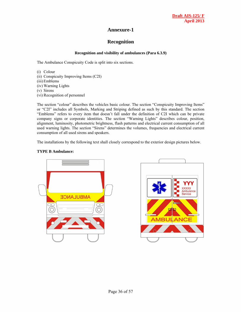
Recognition and visibility of ambulances (Para 6.3.9)
The Ambulance Conspicuity Code is split into six sections. (i) Colour (ii) Conspicuity Improving Items (C2I) (iii) Emblems (iv) Warning Lights (v) Sirens (vi) Recognition of personnel The section “colour” describes the vehicles basic colour. The section “Conspicuity Improving Items” or “C2I” includes all Symbols, Marking and Striping defined as such by this standard. The section “Emblems” refers to every item that doesn’t fall under the definition of C2I which can be private company signs or corporate identities. The section “Warning Lights” describes colour, position, alignment, luminosity, photometric brightness, flash patterns and electrical current consumption of all used warning lights. The section “Sirens” determines the volumes, frequencies and electrical current consumption of all used sirens and speakers. The installations by the following text shall closely correspond to the exterior design pictures below. TYPE B Ambulance:

Draft AIS-125/ F April 2013
Page 37 of 57
TYPE C Ambulance

Draft AIS-125/ F April 2013
Page 38 of 57
TYPE D Ambulance

Draft AIS-125/ F April 2013
Page 39 of 57
(i) Colour : The basic colour of the complete exterior should be brilliant white, RAL-Code 9010, front, rear and side bumpers included. The colour should be weather resistant and withstand daily cleaning and washing.
(ii) Conspicuity Improving Items : This definition includes all marking, striping and symbols as shown in the figure below. All C2I-markings should be in brilliant red, RAL-Code 3024 and in retroreflective quality. Conspicuity Improving Items defined by this standard are: chevron patterns in red/silver and red/yellow, Battenburg patterns, “AMBULANCE” markings, the Star of Life and the emergency number symbol. All “AMBULANCE” markings must follow a 7:1 ratio, length to height. Front: No less than 50% of the front side of the vehicle should be sulfur yellow, RAL-Code 1016 in contrast to no less of 10% brilliant red, RAL Code 9010. The word “AMBULANCE” on yellow background, minimum of 65% of the hood width, shall be in mirror image (reverse reading) for mirror identification by drivers ahead. The front bumper or at least the lower vehicle front up to 70cm or a suitable height within ±30cm should be equipped with retro-reflective striping in a chevron pattern sloping downward and away from the centreline of the vehicle at an angle of 45 degrees. Each stripe in the chevron pattern shall be single colour alternating between fluorescent red and silver. Each stripe shall be 6in. (150mm) in width. Side: The side of the vehicle should be equipped with a two lined red Battenburg pattern on the white ground colour. Starting at the vehicle front the Battenburg squares, with a size of 25cm x 25cm, should reach the middle of the vehicle side and end in a top square, followed by an “AMBULANCE” marking on the same height. The “AMBULANCE” marking should be at least 80% of the Battenburg squares height high. The front half of the Battenburg pattern should be red/yellow squares. The bottom line of the Battenburg pattern should be 25cm above the bottom line of the vehicles chassis, so that the top line of the Battenburg pattern reaches 75cm above the chassis bottom line. Displayed on the upper half of the left side should be a “Star of Life” symbol, with a size of 40cm x 40cm, and the emergency number logo, with a size of 40cm x 75cm. The vertical centre from both of them should match the vertical centre of the side windows of the driver cabin. Contour markings in form of a non-continuous retro-reflecting silver stripe (each part 3cm x 10cm) should be applied to the side profile to

Draft AIS-125/ F April 2013
Page 40 of 57
enhance conspicuity of the vehicle. In Type B, C & D ambulances, the words “Patient Transport”, “Basic Life Support” & “Advanced Life Support” shall be marked respectively just above the word ambulance in size no less than 50% of the size of the word “AMBULANCE” Rear: No less than 50% of the rear of the vehicle should be equipped with a chevron pattern sloping downward and away from the centreline of the vehicle at an angle of 45 degrees. Each stripe in the chevron pattern shall be single colour alternating between fluorescent red and yellow. Each stripe shall be 6in. (150mm) in width. To ensure that the standard rear lights of the vehicle are not camouflaged by the chevron striping, the chevron striping must provide a distance of no less than 10cm to the standard rear lights. The word “AMBULANCE” on yellow background, minimum of 65% in width of the rear facing side of the vehicle but not smaller than 70cm in width, must be mounted at the bottom end of the rear facing doors. Displayed on the left back window should be a “Star of Life” symbol, with a size of 85% of the window, and on the right back window the emergency number logo with the same size. The rear bumper should be provided with the same chevron pattern as the front one. Contour markings in form of a non-continuous retro-reflecting silver stripe should be applied to the rear profile to enhance conspicuity of the vehicle. In Type A Ambulances, the words “FIRST RESPONDER” shall be used instead of “AMBULANCE” wherever applicable. Mild variation in sync with the vehicle design shall be permitted in these markings subject to the fact that not doing so was unavoidable.
(iii) Emblems : Emblems defined as such by this Ambulance Conspicuity Rule are government/ private / operator signs, corporate identities (XXX) and every other sign, symbol, marking or striping not referred to in the “Conspicuity Improving Items” section. These emblems are only allowed in a non-reflecting manner and the size can’t be bigger than 60% of the “AMBULANCE” markings. Ambulance Calling Number (YYY) if available must be displayed prominently on the side and back of the Road ambulance.
(iv) Warning Lights : Type A & B Road Ambulances shall have flashers fitted at appropriate locations as per the vehicle type. Type C & D Road Ambulances shall have warning lights as follows: All warning lights have to be mounted rectangular to the horizontal ground. They must provide 100% of their intensity in a vertical angle of ±4 degrees and 50% in a vertical angle of ±8 degrees. The minimum intensity is for blue and red lights at 100cd at daylight and 200cd in the night. The horizontal minimum angle should be at least 45 degrees. All lights must flash between 2Hz and 4Hz and should be mounted as on the graphic below.

Draft AIS-125/ F April 2013
Page 41 of 57
Lights marked with “red blue” must show red and blue in one piece one at a time. In daytime they must flash red in nighttime they must flash blue. Two lights have to be mounted in the lower middle windshield only flashing to the outside of the car. All lights should be flashing as shown in the graphic above. To switch from Primary into Secondary Mode there has to be one switch that allows only one mode.
(v) Sirens :
In Type A, B, C & D Road Ambulances, all siren loudspeakers have to be mounted on the front of the vehicle. Hidden installation is allowed. The main sound direction must be in driving direction. Permitted are wail and yelp signals that cycle between 10-18 respectively 150-250 per minute at an sound pressure level of 110dB(A) to 120dB(A). The sirens should be tested in accordance with IS 1884 (though not covered in the standard). The frequency range must be at least one octave and should be between 500Hz and 2.000Hz. An Additional electronic air horn can be used. Further there should be a public address system that can be worked at all times ergonomically from the driver’s seat. The siren switch can only be used if the warning lights are on.
(vi) Recognition of personnel :
Safety garments for ambulance personnel should conform to at least ISO 14116:2008.

DRAFT AIS-125/F April 2013
Annexure-2
Technical information to be submitted by the Road Ambulance Manufacturer ( These are additional to the specifications submitted for CMVR compliance as per AIS:007 )
1.0 Details of Ambulance manufacturer
1.1 Name & Address :
1.2 Telephone No :
1.3 Fax. No. :
1.4 E mail address :
1.5 Contact person :
1.6 Name of model :
1.7 Category of Ambulance A/B/C/D
1.8 Name of variants, if any:
1.9 Type and General commercial description (s) :
1.10 Plant/(s)of manufacture :
2.0 Vehicle Chassis Characteristics
2.1 Chassis types approved for Body installation :
2.2 Type of Control (normal control/Full forward control etc.) :
2.3 Number of Axles and wheels :
2.4 Chassis (overall drawing) :
2.5 Valid CMVR certificate for the base Vehicle ( If available )
2.6 Frame Type :
2.7 Cross sectional view :
2.8 Position and arrangement of engine:
2.9 Dimension (in mm) (Specify drawing reference) :
2.9.1 Length mm :
2.9.2 Width mm :
2.9.3 Height (Unladen) mm :
2.9.4 Wheel base mm :
2.9.5 Wheel track mm :
2.9.5.1 Front :
2.9.5.2 Rear :

Draft AIS-125/ F April 2013
Page 43 of 57
2.9.6 Body overhang mm :
2.9.6.1 Front end :
2.9.6.2 Rear end :
2.10 Category of Base vehicle :
3.0 Body :
3.1 Dimension drawing and photograph of the vehicle with representative body :
3.2 Range of vehicle dimension (overall):
3.3 Dimension drawing of the body depicting chassis connecting members :
3.4 Material used for construction :
3.4.1 Structural Material :
3.4.2 Size of sections :
3.5
Method of construction :
(Brief construction method)
3.6 Patient Handling Equipment
3.6.1 Main Stretcher / Undercarriage
3.6.1.1 Make
3.6.1.2 Model
3.6.1.3 Type
3.6.1.4 ID/Part Number
3.6.1.5 Dimensions of Stretcher
3.6.1.6 Loading Angle
3.6.1.7 Loading Height
3.6.1.8 Stretcher loading capacity
3.6.1.9 Compliance to EN 1865
3.6.2 Pick up stretcher
3.6.2.1 Make
3.6.2.2 Model
3.6.2.3 Type
3.6.2.4 ID/Part Number
3.6.2.5 Dimensions of Stretcher
3.6.2.6 Loading Angle
3.6.2.7 Loading Height
3.6.2.8 Stretcher loading capacity
3.6.2.9 Compliance to EN 1865
3.6.3 Vacuum Mattress
3.6.3.1 Make3

Draft AIS-125/ F April 2013
Page 44 of 57
3.6.3.2 Model
3.6.3.3 Type
3.6.3.4 ID/Part Number
3.6.3.5 Dimensions of Stretcher
3.6.3.6 Loading Angle
3.6.3.7 Loading Height
3.6.3.8 Stretcher loading capacity
3.6.3.9 Compliance to EN 1865
3.6.4 Transfer mattress / Carrying Sheet
3.6.4.1 Make
3.6.4.2 Model
3.6.4.3 Type
3.6.4.4 ID/Part Number
3.6.4.5 Dimensions of Stretcher
3.6.4.6 Loading Angle
3.6.4.7 Loading Height
3.6.4.8 Stretcher loading capacity
3.6.4.9 Compliance to EN 1865
3.7 Long spinal board complete with head immobilizer and securing straps
3.7.1 Make
3.7.2 Model
3.7.3 Type
3.7.4 ID/Part Number
3.7.5 Dimensions of Stretcher
3.7.6 Loading Angle
3.7.7 Loading Height
3.7.8 Stretcher loading capacity
3.7.9 Compliance to EN 1865
3.8 Immobilization Equipment
3.8.1 Traction Device
3.8.2 Make
3.8.3 Model
3.8.4 Type
3.8.5 ID/Part Number
3.9 Immobilization, Set of fractures
3.9.1 Make
3.9.2 Model
3.9.3 Type
3.9.4 ID/Part Number

Draft AIS-125/ F April 2013
Page 45 of 57
3.10 Cervical upper spinal immobilization devices Cervical Collar Set
3.10.1 Make
3.10.2 Model
3.10.3 Type
3.10.4 ID/Part Number
3.11 Extended Upper Spinal Immobilization Extrication Devices or Short Spinal Board (one of these)
3.11.1 Make
3.11.2 Model
3.11.3 Type
3.11.4 ID/Part Number
3.12 Recognition of Ambulance
3.12.1 Engineering drawing indicating arrangement for the external visibility for recognition.
3.12.2 Emblems
4.0 Vehicle Dimensions
4.1 Clearance
4.2 Minimum road clearance :
4.3 Road clearance from floor :
4.4 Approach angle :
4.5 Departure Angle :
4.6 Ramp-over Angle :
4.7 Weights
4.7.1 Vehicle kerb weight kg :
4.7.1.1 Front axle :
4.7.1.2 Rear axle :
4.7.1.3 Total :
4.7.2 Gross vehicle weight kg :
4.7.3 Maximum permissible axle weights kg
4.7.3.1 Front axle:
4.7.3.2 Rear axle:
4.8 Vehicle Stability & Roll Over
4.8.1 Max. stable inclination ( Laden Condition )
4.8.1.1 Left deg : 4.8.1.2 Right deg :

Draft AIS-125/ F April 2013
Page 46 of 57
4.8.2 Center of Gravity of the Ambulance in vehicle un laden condition
(X-Y-Z, mm)
4.9 Tyres
4.9.1 No. and arrangement of wheels :
4.9.1.1 Front :
4.9.1.2 Rear :
4.9.1.3 Other :
4.9.2 Inflation pressure – Un laden :
4.9.2.1 Front :
4.9.2.2 Rear :
4.9.2.3 Other
4.9.3 Inflation pressure –Laden :
4.9.3.1 Front :
4.9.3.2 Rear :
4.9.3.3 Other :
5.0 Body Panels
5.1 Outer Panels :
5.1.1 Material :
5.1.2 Thickness :
5.2 Inner Panels :
5.2.1 Material :
5.2.2 Thickness :
5.3 Roof Panels :
5.3.1 Material :
5.3.2 Thickness :
5.4 Floor Panels :
5.4.1 Material :
5.4.2 Thickness :
5.4.3 Type of anti-slip coating :
6.0 Service Doors
6.1 No. of Service Doors :
6.2 Position of Service Doors :
6.3 Dimension of Service Door :
6.3.1 - Front Height :
6.3.2 Width :
6.3.3 - Rear Height :
6.3.4 Width :
6.3.5 - Middle Height :

Draft AIS-125/ F April 2013
Page 47 of 57
6.3.6 Width :
7.0 Window
7.1 Type of window
7.2 Compliance to AIS-068 (Yes/No):
7.3 Area (H x W in sq. m) :
8.0 Seat anchorage layout drawing (with anchorage cross section and hardware used details)
9.0 Driver Partition :
9.1 Dimension of partition with respect to rear edge of driver seat : (rear most position of driver seat)
10.0 External Projections (Compliance established to IS:13943 -1994 ------ Yes / No)
11.0 Door locks and hinges
11.1 Door lock :
11.1.1 Name of Manufacturer :
11.1.2 Identification mark :
11.2 Door hinge :
11.2.1 Name of Manufacturer :
11.2.2 Identification mark :
11.3 Safety glass
11.3.1 Front wind shield (laminated) :
11.3.1.1 Make
11.3.1.2 Identification :
11.3.1.3 Type (flat/curved, clear/tinted) :
11.3.1.4 Thickness mm :
11.3.1.5 No. of pieces :
11.3.1.6 Radius of curvature (If curved) :
11.3.2 Side Windows:
11.3.2.1 Make
11.3.2.2 Identification
11.3.2.3 Type (flat/curved, clear/tinted, toughened) :
11.3.2.4 Thickness mm :
11.3.2.5 Radius of curvature (If curved) :
11.3.3 Rear Window:
11.3.3.1 Make
11.3.3.2 Identification

Draft AIS-125/ F April 2013
Page 48 of 57
11.3.3.3 Type (flat/curved, clear/tinted, toughened) :
11.3.3.4 Thickness mm :
11.3.3.5 Radius of curvature (If curved) :
11.3.4 Wind Screen Wiper
11.3.4.1 Type :
11.3.4.2 No. of wipers :
11.3.5 Wiper motor :
11.3.5.1 Name of Manufacturer :
11.3.5.2 Type and identification :
11.3.5.3 Rated voltage :
11.3.5.4 Frequency of wiping :
11.3.6 Wiper arm :
11.3.6.1 Length :
11.3.6.2 Name of Manufacturer :
11.3.6.3 Identification Mark:
11.3.7 Wiper blade :
11.3.7 .1 Length :
11.3.7 .2 Name of Manufacturer :
11.3.7 .3 Identification Mark:
11.3.8 Rubber material :
11.3.8.1 Type of fixing (As per IS:7827) :
11.3.9 Wind Screen Washer
11.3.9.1 Name of Manufacture: :
11.3.10 Type :
11.3.10.1 Number of nozzles :
11.3.10.2 Spray Area :
11.3.10.3 Identification Number:
12.0 Equipment for occupant's safety
12.1 Driver Seat belt :
12.1.1 Name of Manufacture: :
12.1.2 Type :
12.1.3 Number :
12.1.4 Identification Number:
12.2 Driver Seat belt anchorage :
12.2.1 Name of Manufacturer :
12.2.2 Type :
12.2.3 Number :
12.3 Head restraint :

Draft AIS-125/ F April 2013
Page 49 of 57
12.3.1 Name of Manufacturer :
12.3.2 Type :
12.4 Seat :
12.4.1 Number of Patients and attendant seats
12.4.2 Position
12.4.3 Name of Manufacturer :
12.4.4 Type :
12.4.5 Frame structure Material :
12.4.6 Section size:
12.4.7 Pad material:
12.4.8 Upholstery :
12.4.9 Identification Number:
13.0 Bumper
13.1 Front Size:
13.2 Rear Size:
13.3 Clearance between bumper & body:
14.0 Fire Extinguisher :
14.1 Number :
14.2 Type :
14.3 Capacity :
14.5 Name of Manufacturer :
15.0 Towing devices :
15.1 Type :
15.2 Name of manufacturer :
15.3 Capacity :
15.4 Identification Number / Part No :
16.0 Automotive bulbs : ( To be filled , if different from the valid CMVR Compliance certificate )
16.1 Head lamp bulb (main and dip) :
16.1.1 Make and Country of origin (if imported) :
16.1.2 Designation as per AIS-034 :
16.2 Parking Lamp bulb – Front :
16.2.1 Make and Country of origin (if imported) :
16.2.2 Designation as per AIS-034 :
16.3 Parking Lamp bulb – Rear :

Draft AIS-125/ F April 2013
Page 50 of 57
16.3.1 Make and Country of origin (if imported) :
16.3.2 Designation as per AIS-034 :
16.4 Direction indicator lamp bulb - front :
16.4.1 Make and Country of origin (if imported) :
16.4.2 Designation as per AIS-034 :
16.5 Direction indicator lamp bulb – rear :
16.5.1 Make and Country of origin (if imported) :
16.5.2 Designation as per AIS-034 : 16.6 Direction indicator lamp bulb –
side :
16.6.1 Make and Country of origin (if imported) :
16.6.2 Designation as per AIS-034 :
16.7 Front Position Lamp bulb :
16.7.1 Make and Country of origin ( if imported ) :
16.7.2 Designation as per AIS-034 :
16.8 Rear Position Lamp ( tail lamp )Bulb :
16.8.1 Make and Country of origin (if imported) :
16.8.2 Designation as per AIS-034 :
16.9 Stop lamp bulb :
16.9.1 Make and Country of origin (if imported) :
16.9.2 Designation as per AIS-034 :
16.1 Number plate lamp bulb :
16.10.1 Make and Country of origin (if imported) :
16.10.2 Designation as per AIS-034 :
16.11 End out Marker bulb :
16.11.1 Make and Country of origin (if imported) :
16.11.2 Designation as per AIS-034 :

Draft AIS-125/ F April 2013
Page 51 of 57
16.12 Reversing lamp bulb :
16.12.1 Make and Country of origin (if imported) :
16.12.2 Designation as per AIS-034 :
16.13 Stop Lamp Bulb (S3) :
16.13.1 Make and Country of origin (if imported) :
16.13.2 Designation as per AIS-034 :
16.14 Front Fog Lamp Bulb:
16.14.1 Make and Country of origin (if imported) :
16.14.2 Designation as per AIS-034 :
16.15 Rear Fog Lamp Bulb :
16.15.1 Make and Country of origin (if imported) :
16.15.2 Designation as per AIS-034 :
16.16 Side Marker Lamp Bulb :
16.16.1 Make and Country of origin (if imported) :
16.16.2 Designation as per AIS-034 :
17.0 Head Lamp : ( To be filled if different from the valid CMVR Compliance certificate)
17.1 Name of Manufacturer :
17.2 Type and Identification :
17.3 Number and colour :
18.0 Tail lamp: ( To be filled if different from the valid CMVR Compliance certificate)
18.1 Name of Manufacturer :
18.2 Type and Identification :
18.3 Number and colour :
19.0 Parking lamp : ( To be filled if different from the valid CMVR Compliance certificate)
19.1 Front :
19.1.1 Name of Manufacturer :
19.1.2 Type and Identification :
Draft AIS-125/ F April 2013
Page 52 of 57
19.1.3 Number and colour :
19.2 Rear :
19.2.1 Name of Manufacturer :
19.2.2 Type and Identification :
19.2.3 Number and colour
20.0 Stop lamp : ( To be filled if different from the valid CMVR Compliance certificate)
20.1 Name of Manufacturer :
20.2 Type and Identification :
20.3 Number and colour :
21.0 Reversing lamp: ( To be filled if different from the valid CMVR Compliance certificate)
21.1 Name of Manufacturer :
21.2 Type and Identification :
21.3 Number and colour :
22.0 Direction indicator lamp : ( To be filled if different from the valid CMVR Compliance certificate)
22.1 Front :
22.1.1 Name of Manufacturer :
22.1.2 Type and Identification :
22.1.3 Number and colour : 22.2 Rear :
22.2.1 Name of Manufacturer :
22.2.2 Type and Identification :
22.2.3 Number and colour :
22.3 Side :
22.3.1 Name of Manufacturer :
22.3.2 Type and Identification :
22.3.3 Number and colour :
22.3.4 Type of flasher :
23.0 Number Plate Lamp : ( To be filled if different from the valid CMVR Compliance certificate)
23.1 Name of Manufacturer :
23.2 Type and Identification :

Draft AIS-125/ F April 2013
Page 53 of 57
23.3 Number and colour :
24.0 Warning Lamp : ( To be filled if different from the valid CMVR Compliance certificate)
24.1 Name of Manufacturer :
24.2 Type and Identification :
24.3 Number and colour :
25.0 Siren- Compliance to IS 1884 – Yes / No) :
25.1 Make :
25.2 Model :
25.3 ID / Part Number :
26.0 Reflector : ( To be filled if different from the valid CMVR Compliance certificate)
26.1 Rear :
26.2 Name of Manufacturer :
26.3 Type and Identification :
26.4 Number and colour :
26.5 Area ( cm2):
26.6 Side :
26.7 Name of Manufacturer :
26.8 Type and Identification :
26.9 Number and colour :
26.10 Area ( cm2) :
27.0 Top light : ( To be filled if different from the valid CMVR Compliance certificate)
27.1 Name of Manufacturer: :
27.2 Type and Identification :
27.3 Number and colour :
28.0 Internal Lighting & Illumination
28.1 Driver Cab lighting :
28.1.1 Type :
28.1.2 Name of Manufacturer :
28.1.3 Number :

Draft AIS-125/ F April 2013
Page 54 of 57
28.1.4 Illumination intensity ( Lux) :
28 .2 Patient Compartment Lighting :
28.2.1 Type :
28.2.2 Name of Manufacturer :
28.2.3 Number :
28.2.4 Illumination intensity ( Lux) :
28.3 Other Area Lighting :
28.3.1 Type :
28.3.2 Name of Manufacturer :
28.3.3 Number :
28.3.4 Illumination intensity ( Lux) :
29.0 Electrical Circuit :
29.1 Circuit Diagram (attach details):
29.2 Number of battery(ies) provided other than the vehicle battery :
29.3 Details of Alternator :
30.0 Electrical Cables :
30.1 Name of Manufacturer :
30.2 Conductor Cross section :
30.3 Insulation Class :
31.0 Fuse :
31.1 Type & Make :
31.2 Name of Manufacturer :
32.0 Master switch for electrical :
32.1 Type & Make :
32.2 Name of Manufacturer :
33.0 Flammability Test as per IS 15061: 2002 (as applicable ) :
34.0 Interior fitting compliance as per AIS-047 established - Yes/No :
35.0 Instrument Panel (Dash Board) :
35.1 Make :
35.2 Identification No. / Part No. :
35.3 Material :

Draft AIS-125/ F April 2013
Page 55 of 57
35.4 Drawing showing the mounting details, over all size and all control switches with dimensions :
35.5 Additional details for interior fitting tests to be given (if test is already conducted, this information need not be submitted) :
35.6 Instrument Panel Variants with photographs (With / without Airbag, Music system, AC ) :
35.7 Material used for instrument Panel :
35.8 Drawings :
35.9 Drawing of Grab handle with cross section :
35.10 Drawing of lamp assembly mounted at roof :
35.11 Name of manufacturer of the Interior fitting components :
36.0 Air Conditioning & Heating Performance Tests(Clause 4.5.4) Compliance Established –Yes / No
37.0 Acceleration Test (Clause 4.2.1 & IS:11851-2002) Compliance Established –Yes / No
38.0 Water Proofing Test ( IS:11865-1995) – Compliance Established –Yes / No
39.0 Dust Ingress Test (IS:11739-1997) Compliance Established –Yes / No

Draft AIS-125/ F April 2013
Page 56 of 57
Annexure 3 (See Introduction)
COMPOSITION OF AISC PANEL
Name Organization
Dr. Shakti Kumar Gupta (Chairman)
Head, Department of Hospital Administration & Medical Superintendent (Dr. Rajendra Prasad Centre of Ophthalmic Sciences & JPNA Trauma Centre), AIIMS, New Delhi
Dr. D.K. Pawar Professor, Department of Anaesthesiology, AIIMS, New Delhi
Brig. (Med.) Pawan Kapoor Army Medical Corps, HQ 16 Core, C/o 56 APO.
Mr. A. Akbar Badusha Deputy Director & Head, Vehicle Evaluation Lab, ARAI, Pune
Dr. A.R. Goyal
Director, Finance, MoRTH, Govt. of India
Mr. Rajeev Lochan
Director (RS), MoRTH, Govt of India
Col. Sunil Kant Directing Staff, Officers Training College, AMC Centre & College, Lucknow
Mr. S.N. Das C.E. (Mech), MoRTH, Govt. of India
Mr. R.P. Khandelwal CGM (Safety), NHAI, Govt. of India
Dr. Chaman Prakash CMO, Dt.GHS, MoHFW, Govt. of India
Dr. Ritu Rawat Senior Medical Superintendent, Apollo Hospitals
Lt. Col. S.K. Patnaik Medical Officer, Hospital Services, Military Hospital, Hissar
Dr. Angel Rajan Singh Senior Resident Administrator, Department of Hospital Administration, AIIMS, New Delhi
Mr. R.K. Chawla DGM (CM), NHAI, Govt. of India
Mr. K.C. Sharma E.E. (M), MoRTH, Govt. of India
Mr. Jashvant Prajapati Chief Operating Officer at GVK EMRI- Gujarat
Dr. G.V. Ramanarao Head, EM Learning Centre & Research, GVK EMRI
Mr. B.N. Mishra Under Secretary (RS), MoRTH, Govt. of India
Mr. Kamal Gulati AIIMS, New Delhi
Mr. K.K.Gandhi Representing SIAM and its members

Draft AIS-125/ F April 2013
Page 57 of 57
Annexure 4 (See Introduction)
COMMITTEE COMPOSITION * Automotive Industry Standards Committee
(To be included)