construction training qualification program asphalt plant ... plant 2/13 - appendix 3 _july... ·...
TRANSCRIPT
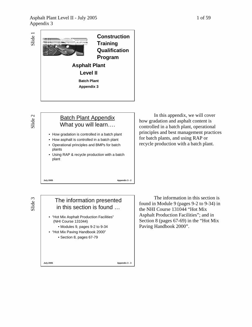
Asphalt Plant Level II - July 2005 1 of 59 Appendix 3
Slid
e 1
Batch PlantAppendix 3
ConstructionTrainingQualification Program
Asphalt Plant Level II
Sl
ide
2
July 2005 Appendix 3 - 2
Batch Plant AppendixWhat you will learn….
• How gradation is controlled in a batch plant• How asphalt is controlled in a batch plant• Operational principles and BMPs for batch
plants• Using RAP & recycle production with a batch
plant
In this appendix, we will cover how gradation and asphalt content is controlled in a batch plant, operational principles and best management practices for batch plants, and using RAP or recycle production with a batch plant.
Slid
e 3
July 2005 Appendix 3 - 3
The information presented in this section is found …
• “Hot Mix Asphalt Production Facilities”(NHI Course 131044)
• Modules 9, pages 9-2 to 9-34• “Hot Mix Paving Handbook 2000”
• Section 8, pages 67-79
The information in this section is found in Module 9 (pages 9-2 to 9-34) in the NHI Course 131044 “Hot Mix Asphalt Production Facilities”; and in Section 8 (pages 67-69) in the “Hot Mix Paving Handbook 2000”.

Asphalt Plant Level II - July 2005 2 of 59 Appendix 3
Slid
e 4
July 2005 Appendix 3 - 4
The Modern BatchPlant Facility
- Final gradation is determined at the hotbins with aggregate“weigh hopper”
- Asphalt content isdetermined using theasphalt “weigh bucket”
This shows how material actually moves through a batch facility. Once crushed aggregate is dried it is conveyed to the top of the screening section with the aid of a bucket elevator. At the screening unit, the aggregate flow passes over different screens that separates the aggregate into different sizes. Sized aggregates are then stored in the “hot bins”, so called because they contain the hot, dried aggregate, which is waiting to be dispensed into the aggregate weigh hopper. The gates below these bins are typically referred to as “supply gates” or “hot bin gates”. The plant operator either manually or automatically “draws” material from each hot bin to match the job-mix formula and weighs the aggregate in the aggregate “weigh hopper,” which is positioned directly below the hot-bin gates. Asphalt is pumped into the asphalt “weigh bucket,” where it is weighed to the required amount. In modern, automated plants, the aggregate weighing and asphalt weighing is done simultaneously to shorten the batch cycle. The aggregate is discharged from the aggregate weigh hopper into the “pugmill”, where it is mixed for a brief period of time without asphalt cement to thoroughly mix the aggregate from each supply bin. This is called the “dry-mix cycle”. After the dry-mix cycle, the asphalt cement is discharged in the pugmill, where it is mixed with the blended aggregate in a “wet-mix cycle”. The hot-mix is then dispensed into a waiting vehicle or into transfer equipment for storage in a silo. Note that the final aggregate gradation is determined at the aggregate “weigh hopper” and asphalt content is determined in the asphalt “weigh bucket” in a batch type plant.

Asphalt Plant Level II - July 2005 3 of 59 Appendix 3
Slid
e 5
July 2005 Appendix 3 - 5
The Modern BatchPlant Facility
- Final gradation is determined at the hotbins with aggregate“weigh hopper”
- Asphalt content isdetermined using theasphalt “weigh bucket”
In a batch facility aggregate gradation is controlled at the aggregate “weigh hopper” by drawing different quantities of material from each hot bin. Asphalt content is controlled in the asphalt “weigh bucket” by weighing up the desired quantity of asphalt for each batch.
Slid
e 6
July 2005 Appendix 3 - 6
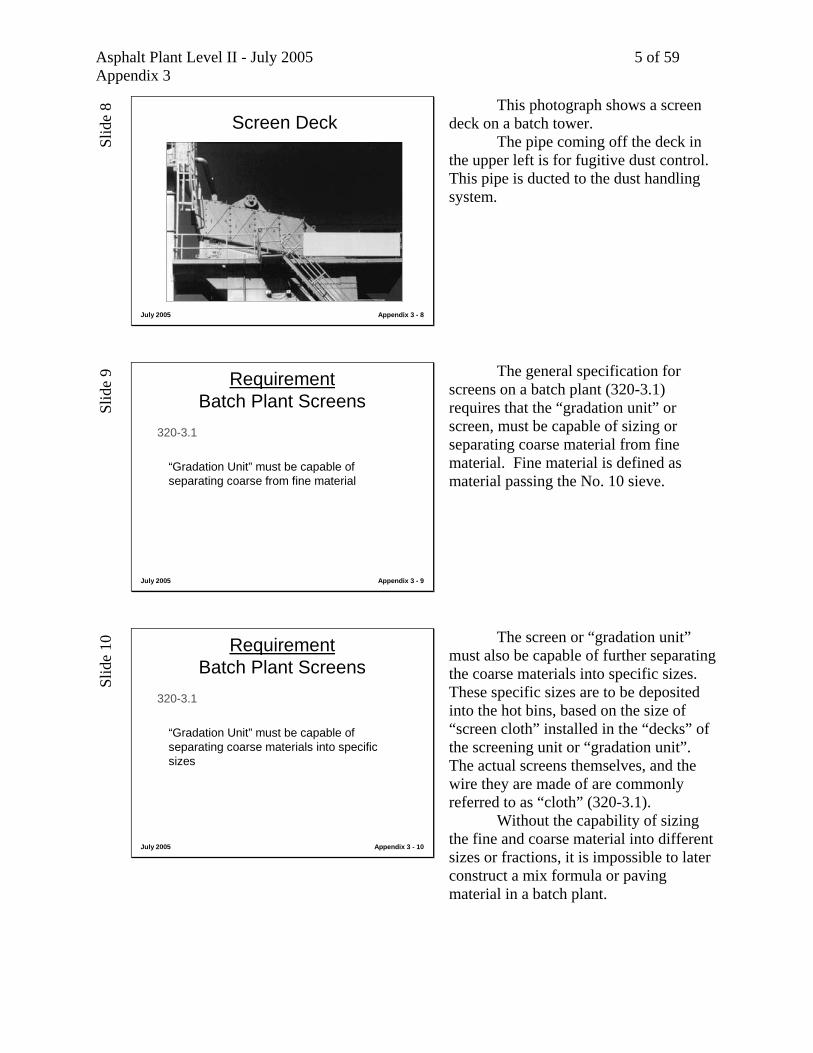
Screen Deck
After the trip up the hot elevator, material first passes over the screen deck.

Asphalt Plant Level II - July 2005 4 of 59 Appendix 3
Slid
e 7
July 2005 Appendix 3 - 7
Screen Deck Here material passes over several different sized screens, referred to as “decks”. As material successfully passes down through the screen “cloth” on each “deck”, it is directed into one of the hot bins in the batch tower. Material that passes through all the decks is deposited into the hot bin closest to the hot elevator. This is commonly referred to as the “fines bin” or No. 1 bin. This bin typically has -#10 material in it, and is the fine aggregate bin. Material retained on the deck over the fines bin, but passing through all other screen decks ends up in the No. 2 bin. Bins are numbered from the hot elevator. Most plants have four hot bins, but some have five. Some plants were constructed with three hot bins, and some with six, but these are rare to find in the field. Material that is retained on the screen sizing for the No. 2 bin, but passing all other screens is directed to the No. 3 bin. This type of sizing process continues to fill all the hot bins on the plant. Material that is retained on all screens is rejected from the tower through the overflow chute. We will see an illustration and photograph of this device later.
Asphalt Plant Level II - July 2005 5 of 59 Appendix 3
Slid
e 8
July 2005 Appendix 3 - 8
Screen Deck This photograph shows a screen deck on a batch tower. The pipe coming off the deck in the upper left is for fugitive dust control. This pipe is ducted to the dust handling system.
Slid
e 9
July 2005 Appendix 3 - 9
RequirementBatch Plant Screens
320-3.1
“Gradation Unit” must be capable of separating coarse from fine material
The general specification for screens on a batch plant (320-3.1) requires that the “gradation unit” or screen, must be capable of sizing or separating coarse material from fine material. Fine material is defined as material passing the No. 10 sieve.
Slid
e 10
July 2005 Appendix 3 - 10
RequirementBatch Plant Screens
320-3.1
“Gradation Unit” must be capable of separating coarse materials into specific sizes
The screen or “gradation unit” must also be capable of further separating the coarse materials into specific sizes. These specific sizes are to be deposited into the hot bins, based on the size of “screen cloth” installed in the “decks” of the screening unit or “gradation unit”. The actual screens themselves, and the wire they are made of are commonly referred to as “cloth” (320-3.1). Without the capability of sizing the fine and coarse material into different sizes or fractions, it is impossible to later construct a mix formula or paving material in a batch plant.

Asphalt Plant Level II - July 2005 6 of 59 Appendix 3
Slid
e 11
July 2005 Appendix 3 - 11
RequirementBatch Plant Screens
320-3.1
“Gradation Unit” must be capable of scalping off the oversized material
Material that does not pass through the sizing screens is retained on the top screen and is rejected out of the tower (320-3.1). This requirement, satisfied by the top deck of the screen, protects the quality and integrity of the mix by providing a means for oversized material that may have found its way into the stockpile or cold feed bin from being deposited in one of the hot bins in the tower.
Slid
e 12
July 2005 Appendix 3 - 12
RequirementBatch Plant Screens
330-5.7.2
Do not exceed capacity of screens to separate aggregates
Requirement 330-5.7.2 stipulates that the contractor must not exceed the capacity of the screens. This operational guideline for plant operations is critical. If more material is deposited on the screens than the screens are capable of sizing and separating, then smaller materials will ride with the larger materials into the larger hot bins because they have not had a chance of being separated from the larger materials. This places the smaller materials in bins that are not appropriate, and affects the gradation of the individual hot bins. This makes it very difficult to construct a mix formula. The consistency of a batch plant depends on the consistency of sizing the fine and coarse materials into their proper fractions, as defined by the screens installed in the screen deck. Overfeeding a screen destroys the effectiveness of this activity.

Asphalt Plant Level II - July 2005 7 of 59 Appendix 3
Slid
e 13
July 2005 Appendix 3 - 13
RequirementScalping Screen
330-5.7.1
Remove oversize with scalping screen and do not re-use without re-crushing and re-screening
Another requirement, found in the 330 section of the Florida specifications again refers to the function of scalping off the oversized material, but further stipulates that it must not be re-fed into the plant or re-used with out re-crushing and re-screening. The Engineer will want to monitor that material from the oversize chute is placed in a reject pile for later processing or use in other purposes by the contractor.
Slid
e 14
July 2005 Appendix 3 - 14
RequirementBatch Plant Screens
330-5.7.2
Only 10% plus-10 material allowed in the minus-10 bin, and ….
Engineer to determine maximum amount of minus-10 material allowed in plus-10 bins (coarse material bins)
Specification 330-5.7.2 defines the tolerance of gradation allowed in the fine and coarse bins. Every size specification has to have a tolerance band, because we don’t live in a perfect world. This spec acknowledges that up to 10% plus 10 material is allowed in the fines bin, but it leaves to the judgment of the Engineer to define the amount of fine aggregate, or minus 10 material that can be allowed in the coarser bins. When in doubt about whether there is too many fines, or minus 10 material in the coarse aggregate bins, consult the District Bituminous Engineer for guidance.
Slid
e 15
July 2005 Appendix 3 - 15
Best Management PracticesScreen Deck
Let’s review the Best Management Practices for the screen deck area.

Asphalt Plant Level II - July 2005 8 of 59 Appendix 3
Slid
e 16
July 2005 Appendix 3 - 16
Best Management PracticesScreen Deck
• Check for worn cloth or holes (hot bin gradations typically get coarser)
• Check side plates for wear (can contaminate bins by causing fine particles to flow to coarse bins)
• Check chutes for worn holes (hot bin gradations get coarser)
(all these items negatively affect gradations in hot bins)
These items are typical operational inspection items that help ensure the screen deck is functioning correctly, and that aggregate is getting properly sized. Worn cloth or holes in the screen cloth will allow coarse materials through, and cause the hot bin samples to start getting coarser. Some screen decks have side plates, that if worn, can cause fine materials to flow to coarse bins. Chutes that direct the material into the hot bins are angled. Refer back to the illustration of a screen deck. If they develop holes, coarser material typically falls into finer bins. The operator typically opens the inspection doors on the screen deck and visually inspects the unit for the wear on the cloth, side plates, and chutes.
Slid
e 17
July 2005 Appendix 3 - 17
Best Management PracticesScreen Deck
• Do not overfeed a screen beyond its capability (causes finer material to carry over into the larger hot bins)
• Make sure the aggregate is dry…wet material can “blind” a screen (also causes finer material to carry over into the larger hot bins)
(all these items negatively affect gradations in hot bins)
Feeding a screen with more material than it can handle can cause finer materials to carry over to the coarser bins. Material that is not properly dried can also cake or the screens. This is called “blinding”. This reduces the area of the screen, which reduces its capability of sizing material, and can also cause finer materials to flow into the coarse bins. This has the same net affect as overfeeding a screen. This is another reason why it is imperative that the material is dried sufficiently in the aggregate dryer.
Asphalt Plant Level II - July 2005 9 of 59 Appendix 3
Slid
e 18
July 2005 Appendix 3 - 18
Class Discussion
• No. 1, “fines”, minus-10 bin, hot bin samples are suddenly getting coarser.
• Nothing else has changed. No weather change. No temperature change. No production change.
(What could be happening?)(Where might we go to look?)
Now lets visualize possible causes for this situation. The No. 1 bin, or “fines” bin hot bin samples are suddenly getting coarser. Nothing else has changed. Everything has been going just fine. What could be happening? Where might we go to look or what area of the plant do we inspect?
Slid
e 19
July 2005 Appendix 3 - 19
Class Discussion
• The weather has been dry for several days.• The contractor is really able to get some production
out because the dryer can really dry the material.• This is the contractor’s opportunity to make up for lost
time on the job. What luck!• Whoops! Bin pulls suddenly got finer!
(What could be happening?)(Where might we go to look?)
Let’s consider the weather situation we all hope for, especially when we’re behind on a job. The stockpiles are dry. It hasn’t rained for days. The operator is really able to get some production out of the dryer. Suddenly the hot bin pulls get finer. What could be happening? Where might we go to look or what area of the plant do we inspect?
Slid
e 20
July 2005 Appendix 3 - 20
Hot Storage Bins
Once the material is sized by the screens it is deposited into the hot storage bins.

Asphalt Plant Level II - July 2005 10 of 59 Appendix 3
Slid
e 21
July 2005 Appendix 3 - 21
Hot Storage Bins
Most plants have four or five hot bins. Some plants were made with three hot bins, and a few were made with six. Hot bin capacity in a batch plant is typically about 40-50% dedicated to the No. 1 of fines bin. The rest of the capacity is spread between the coarse material bins. Some plants have substantially hot bin capacity. Batch plants with up to 350 tons of hot rock storage have been manufactured. Most plants have 40-80 tons of storage depending on the size of the plants, with portable batch plants having the least amount of storage. With a portable batch plant, or a batch plant with a small amount of hot storage, balancing the cold feed flow to match the hot bin pulls is critical.
Slid
e 22
July 2005 Appendix 3 - 22
RequirementBatch Plant Hot Bins
320-3.2
Must be divided compartments to keep the aggregate fractions separate (different sizes)
Specs require the hot bins are divided into compartments to keep the aggregate fractions separate (320-3.2).
Asphalt Plant Level II - July 2005 11 of 59 Appendix 3
Slid
e 23
July 2005 Appendix 3 - 23
RequirementBatch Plant Hot Bins
320-3.2
Must be equipped with overflow chutes
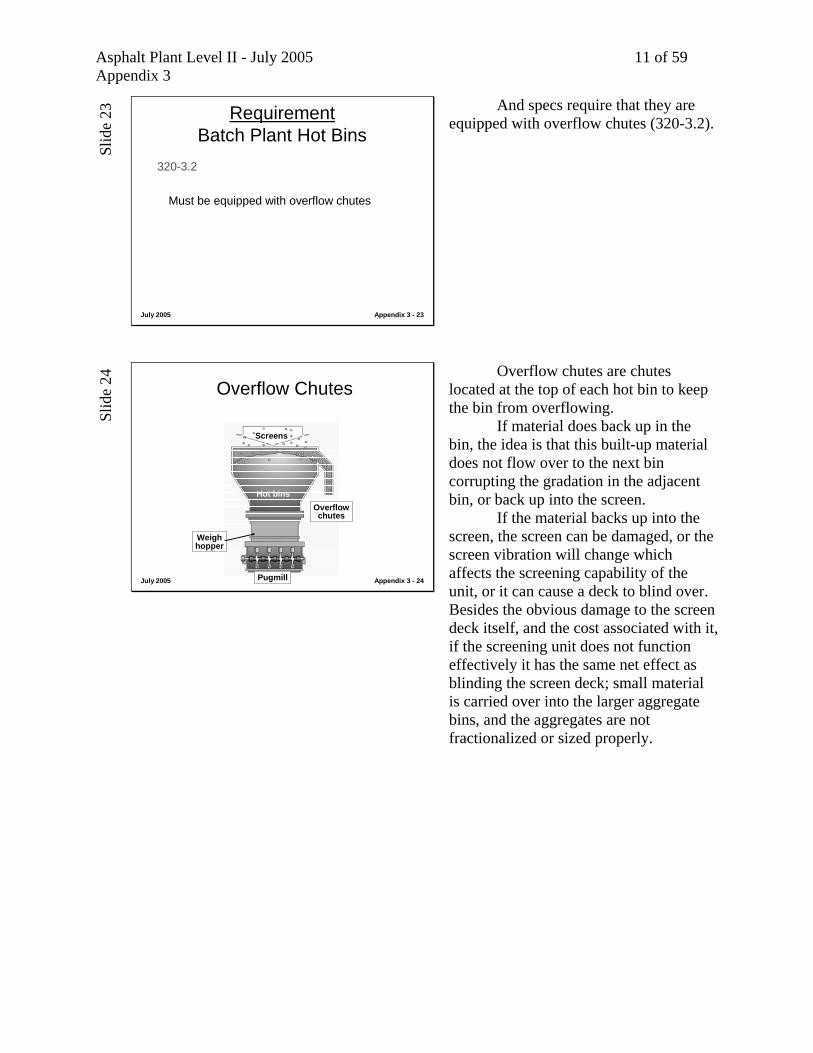
And specs require that they are equipped with overflow chutes (320-3.2).
Slid
e 24
July 2005 Appendix 3 - 24
Overflow Chutes
Overflowchutes
Hot bins
Screens
Weighhopper
Pugmill
Overflow chutes are chutes located at the top of each hot bin to keep the bin from overflowing. If material does back up in the bin, the idea is that this built-up material does not flow over to the next bin corrupting the gradation in the adjacent bin, or back up into the screen. If the material backs up into the screen, the screen can be damaged, or the screen vibration will change which affects the screening capability of the unit, or it can cause a deck to blind over. Besides the obvious damage to the screen deck itself, and the cost associated with it, if the screening unit does not function effectively it has the same net effect as blinding the screen deck; small material is carried over into the larger aggregate bins, and the aggregates are not fractionalized or sized properly.
Asphalt Plant Level II - July 2005 12 of 59 Appendix 3
Slid
e 25
July 2005 Appendix 3 - 25
Overflow chutes
Bin 1 2 3 4
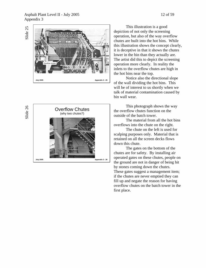
This illustration is a good depiction of not only the screening operation, but also of the way overflow chutes are built into the hot bins. While this illustration shows the concept clearly, it is deceptive in that it shows the chutes lower in the bin than they actually are. The artist did this to depict the screening operation more clearly. In reality the inlets to the overflow chutes are high in the hot bins near the top. Notice also the directional slope of the wall dividing the hot bins. This will be of interest to us shortly when we talk of material contamination caused by bin wall wear.
Slid
e 26
July 2005 Appendix 3 - 26
Overflow Chutes(why two chutes?)
This photograph shows the way the overflow chutes function on the outside of the batch tower. The material from all the hot bins overflows into the chute on the right. The chute on the left is used for scalping purposes only. Material that is retained on all the screen decks flows down this chute. The gates on the bottom of the chutes are for safety. By installing air operated gates on these chutes, people on the ground are not in danger of being hit by stones coming down the chutes. These gates suggest a management item; if the chutes are never emptied they can fill up and negate the reason for having overflow chutes on the batch tower in the first place.

Asphalt Plant Level II - July 2005 13 of 59 Appendix 3
Slid
e 27
July 2005 Appendix 3 - 27
Hot Bin Indicators
Rotary bin indicators, called hot bin indicators, help the operator manage his plant operation by informing him if the bins are too full or too empty. This helps the operator balance his cold feed flow to his hot bin pulls. Balancing cold feed flow to hot bin pulls is critical to producing a consistent and uniform mix. This ensures that there is sufficient quantity of material in each hot bin for each batch of the mix formula.
Slid
e 28
July 2005 Appendix 3 - 28
Best Management PracticesHot Bins
BIN 1 2 3 4
Let’s review the Best Management Practices for the hot bins.
Asphalt Plant Level II - July 2005 14 of 59 Appendix 3
Slid
e 29
July 2005 Appendix 3 - 29
Best Management PracticesHot Bins
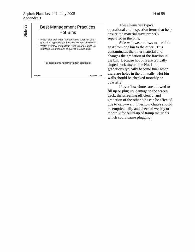
• Watch side wall wear (contaminates other hot bins -gradations typically get finer due to slope of bin wall)
• Watch overflow chutes from filling up or plugging up (damage to screen and carryover to other bins)
(all these items negatively affect gradation)
These items are typical operational and inspection items that help ensure the material stays properly separated in the bins. Side wall wear allows material to pass from one bin to the other. This contaminates the other material and changes the gradation of the fraction in the bin. Because hot bins are typically sloped back toward the No. 1 bin, gradations typically become finer when there are holes in the bin walls. Hot bin walls should be checked monthly or quarterly. If overflow chutes are allowed to fill up or plug up, damage to the screen deck, the screening efficiency, and gradation of the other bins can be affected due to carryover. Overflow chutes should be emptied daily and checked weekly or monthly for build-up of tramp materials which could cause plugging.

Asphalt Plant Level II - July 2005 15 of 59 Appendix 3
Slid
e 30
July 2005 Appendix 3 - 30
Best Management PracticesHot Bins
• Malfunctioning hot bin indicators can also cause carryover to another bin by incorrectly over-filling a bin.
• Match cold feed flow to hot bin pull, especially on plant with small hot bins (can affect both production rates and consistency of mix)
(all these items negatively affect gradation)
Malfunctioning bin indicators can provide a false reading to the operator, causing him to overfill one of his hot bins by feeding too much of that fraction at the cold feed. Overfull bins can contaminate material in adjacent bin, negatively impacting the gradation consistency, especially if the overflow chutes are not functioning properly. It is important that the operator give every effort at balancing cold feed flow to hot bin pulls, especially when the batch plant does not have too large of storage capacity in the hot bins. Production rates are affected because the plant cannot batch if the dryer is trying to catch up with a given fraction. Drying efficiency may be affected because the veil and drying characteristics might change in the dryer. The consistency of the mix can be affected if the batch quantities of the individual aggregates are not all within the same tolerance bands.
Slid
e 31
July 2005 Appendix 3 - 31
Class Discussion
• Production has been going well on a fine Superpave mix formula
• Suddenly No. 1 hot bin pulls start showing small aggregate fractions in them…not to high a percentage…but they’re there.
(What could be happening?)(Where might we go to look?)
Let’s review possible causes for this theoretical situation. A fine Superpave mix formula produced with a batch plant has just been going like clockwork. Everyone is happy. Life is rosy. Suddenly the hot bin pulls start showing small aggregate fractions, the size found in the No. 2 bin, showing up in the No. 1 bin. The percentage isn’t too high, and it probably won’t throw off the mix formula and push the job to penalty on extracted graded, but something has changed. What could be happening? Where might we go to look?

Asphalt Plant Level II - July 2005 16 of 59 Appendix 3
Slid
e 32
July 2005 Appendix 3 - 32
Class Discussion
• Hot bin samples suddenly become finer in No. 3 bin.
• Each test shows same change in gradation.• Change is enough to affect final mix formula• Recalibrate plant? Change hot bin draws on
mix formula?
(What could be happening?)(Where might we go to look?)
Now let’s think about this situation. Hot bin samples suddenly become finer in the No. 3 bin. Each test shows the same change in gradation. The change is significant enough that everyone is discussing recalculating the hot bin pulls and re-calibrating. What could be happening? Where might we go for a look?
Slid
e 33
July 2005 Appendix 3 - 33
Hot Bin Gates
The gates located below the hot bins are referred to as the hot bin gates, or the supply gates.
Slid
e 34
July 2005 Appendix 3 - 34
Hot Bin Gates They are typically operated with electrically actuated air or hydraulic cylinders that are connected directly to the gates.
Asphalt Plant Level II - July 2005 17 of 59 Appendix 3
Slid
e 35
July 2005 Appendix 3 - 35
RequirementHot Bin Sampling
320-3.3
Provide convenient and accurate means for sampling hot bins
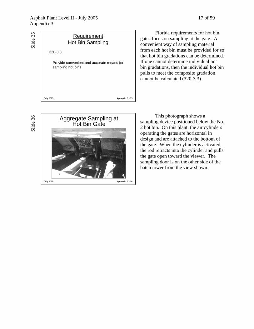
Florida requirements for hot bin gates focus on sampling at the gate. A convenient way of sampling material from each hot bin must be provided for so that hot bin gradations can be determined. If one cannot determine individual hot bin gradations, then the individual hot bin pulls to meet the composite gradation cannot be calculated (320-3.3).
Slid
e 36
July 2005 Appendix 3 - 36
Aggregate Sampling at Hot Bin Gate
This photograph shows a sampling device positioned below the No. 2 hot bin. On this plant, the air cylinders operating the gates are horizontal in design and are attached to the bottom of the gate. When the cylinder is activated, the rod retracts into the cylinder and pulls the gate open toward the viewer. The sampling door is on the other side of the batch tower from the view shown.
Asphalt Plant Level II - July 2005 18 of 59 Appendix 3
Slid
e 37
July 2005 Appendix 3 - 37
RequirementBatch Plant Calibration
334-5.3 Initial Production Requirements
• “The Initial Production Lot of all mix designs shall be established at 2000 ton [2000 m ton]
• “During this period the Contractor shall demonstrate the capability to produce and place the mixture as specified unless waived by the Engineer…
(rule applies other mix types - cross referenced to 334-5.3)
The specifications are not as specific as in the recent past about initial calibration of the batch plant. 334-5.3 now simply requires that the Contractor is able to demonstrate in the initial 2000 ton Production Lot that he is capable of producing the mix to the quality requirements. Other mix types, such as 337 mixes, will cross-reference a similar requirement to 334-5.3. One example whereby an Engineer might consider waiving this requirement is the Contractor had recently completed an FDOT project, and the Engineer knew the plant was fully calibrated and capable of accurate production to the new Job Mix Formula.
Slid
e 38
July 2005 Appendix 3 - 38
Best Management PracticesHot Bin Gates
Let’s look at Best Management Practices for the hot bin gate area.
Asphalt Plant Level II - July 2005 19 of 59 Appendix 3
Slid
e 39
July 2005 Appendix 3 - 39
Best Management PracticesHot Bin Gates
• Gates wear (can cause overflow into weigh hopper)• Gates hinge pins fail (causing gates not to close
correctly - negatively affecting gradation)• Gate/bin opening clearances wear (can also cause
leakage)
(all items affect material gradation)
These items are typical operational and inspection items for hot bin gates. Gates wear and this can cause material to leak, thus affecting the amount of material discharged into the weigh hopper. A simple way to watch for this is to see if weights accumulate slowly in the weigh hopper when not batching. Gate hinge pins can also fail, causing the gates not to close correctly. This, obviously, will have a negative affect on the gradation of the material. The clearance between the gate and the bin opening also wears due to the abrasiveness of the aggregate. This will affect the opening where materials can leak by the gate, especially in the finer aggregate bins. Gates should be inspected weekly or monthly for smooth operation and wear. They should be repaired and clearances re-established to protect the gradation consistency of the mix.
Slid
e 40
July 2005 Appendix 3 - 40
Best Management PracticesHot Bin Gates
• Take samples across full flow of material from hot bin (might not represent actual hot bin gradation)
• Gate cylinders wear causing them to not close smoothly or quickly (can affect cutoff values on hot bin draws changing gradation)
(all items affect material gradation)
Hot bin samples should be taken across the full cross-sectional flow of material from the hot bin. Material can segregate in the hot bin, and if the sample is not taken across the full stream of material as it exits the bin, then test results will not represent the actual gradations of the bin, and incorrect mix production will result. This point is critical to proper batch plant operation. Gate cylinders also wear, which can cause them to hang-up or open erratically. This can affect the cut-off values on the hot bin draws, which can affect the final gradation of the mix.

Asphalt Plant Level II - July 2005 20 of 59 Appendix 3
Slid
e 41
July 2005 Appendix 3 - 41
Class Discussion
• The batch weights on the computer for the No. 1 bin are showing wider swings on actual-vs-target tolerance than what it has been running.
• The weights are within the mix formula.• There doesn’t seem to be any consistency in the
target to actual difference. Sometimes its high, sometimes its low.
• Everyone is wondering what is going on.
(What could be happening?)(Where might we go to look?)
Let’s discuss this situation. Everything, as usual, has been going fine. But now the batch weights as shown on the computer screen are showing the actual to target tolerance in the No. 1 bin with wider variation. The actuals to target are inconsistent. Sometimes they’re high, sometimes they’re low. The plant is still within spec tolerance range, but everyone is wondering what is going on. What could be happening? Where might we go for a look?
Slid
e 42
July 2005 Appendix 3 - 42
Class Discussion
• Life is rosy. The weather’s great, production rates are great, the mat is great, test results are great. Everyone wants to head for home early.
• Someone notices that if the operator waits to drop the batch into the pug while a truck positioning, the indicator for the weigh hopper keeps climbing slowly.
• That’s a problem! Time to work on the plant tonight….
(What could be happening?)(Where might we go to look?)
Let’s theorize that today is one of those perfect production days you always hoped for. The weather is great, the production rates are great, the mat looks good. All the tests are right on the money. Everyone is discussing knocking off earlier than usual to spend a little time with the family. Suddenly someone notices the weigh hopper indicator climbing slowly while trucks are jockeying for position in the drive through. Everyone suddenly gets in a bad mood. What could be happening? Where might we go to look?
Slid
e 43
July 2005 Appendix 3 - 43
Aggregate Weigh Hopper
Material from the hot bins discharges into the aggregate weigh hopper.

Asphalt Plant Level II - July 2005 21 of 59 Appendix 3
Slid
e 44
July 2005 Appendix 3 - 44
Aggregate Weigh Hopper
AggregateWeighHopper
AsphaltWeighBucket
The aggregate weigh hopper is positioned directly below the hot bin gate area. It is designed to be a scale, and is attached to a mechanical scale linkage or is supported from load cells.
Slid
e 45
July 2005 Appendix 3 - 45
Weigh Hopper This photograph shows the position of the weigh hopper in the batch tower. It sits on the deck where the gate cylinders and hot bin sample doors are located.
Slid
e 46
July 2005 Appendix 3 - 46
RequirementBatch Plant Weigh Hopper
320-3.4 Weigh Hopper
Must be on scales, must be able to accept full batch without running over, must have gates that prevent leakage, must operate smoothly without being “thrown out of alignment”
Florida requirements (320-3.4) stipulate that the aggregate weigh hopper must be on a scale, and be capable of accepting a full batch size of the tower’s rated capacity without running over (overfilling). The gates have to be designed to prevent leakage. The weigh hopper must operate smoothly, and be loadable without danger of binding the linkage or throwing it out of alignment.

Asphalt Plant Level II - July 2005 22 of 59 Appendix 3
Slid
e 47
July 2005 Appendix 3 - 47
RequirementBatch Plant Batch Scales
320-2.2 Electronic Weigh Systems
Must be calibrated every six months by registered scale technician (to Florida Dept of Agriculture Bureau of Weights and Measures accuracy requirements)
The weigh hopper is a scale, and if the batch plant is not equipped with silos, will be used to “sell” material to the department. Therefore, the scales must be calibrated every six months. They must be accurate to the Florida Department of Agriculture Bureau of Weights and Measures accuracy requirements (320-2.2). Typically a certified scale technician performs this task, and places a seal on the indicator.
Slid
e 48
July 2005 Appendix 3 - 48
RequirementBatch Plant Weights
320-2.2.4.2 Check Weights Weekly• Randomly select a truck• Record gross weights• Record truck number• Weigh on another certified scale not owned
by contractor - (if too far away then another scale by contractor is OK)
If mix is being ticketed from the batch tower, the batch scales must be checked weekly during production like a truck scale (320-2.2.4.2). There is a specific procedure for this. A truck must be selected at random. The total batch weight on the ticket is checked by weighing the truck on another certified scale not owned by the contractor. This is done after the empty weight of the truck is determined, and the total or gross weights are compared.
Slid
e 49
July 2005 Appendix 3 - 49
RequirementBatch Plant Weights (cont.)
320-2.2.4.2• If the scale is far away, or the job is far
away…• The truck weights should be adjusted for fuel
loss based on the fuel adjustment of 6.1 mpg for the truck consumption and 115 ounces per gallon for weight of fuel
If the checking scale is a long distance away, or if the trip to the job site is significant, the checking weights have to be adjusted for fuel loss. Change the weights by calculating the distance driven, and adjusting the weights for a fuel consumption of 6.1 mpg and a fuel weigh of 115 ounces per gallon. Details on this guideline are found in 320-2.2.4.2.

Asphalt Plant Level II - July 2005 23 of 59 Appendix 3
Slid
e 50
July 2005 Appendix 3 - 50
Mechanical Lever Scales for Weigh Hopper
This photograph shows the typical type of scale linkage found on a weigh hopper with a mechanical lever type scale.
Slid
e 51
July 2005 Appendix 3 - 51
Load Cell Mounted in Linkage of Mechanical Lever Scale
Most mechanical scales have been modified with the installation of a load cell in the linkage which operates a digital instrument on the batch automation in the control house.
Slid
e 52
July 2005 Appendix 3 - 52
Modern Load Cell Style Weigh Hopper w/o Lever Arm Scale
Newer batch plants have weigh hoppers suspended directly on these load cells, and do not have mechanical linkage that pivots and moves.

Asphalt Plant Level II - July 2005 24 of 59 Appendix 3
Slid
e 53
July 2005 Appendix 3 - 53
Best Management PracticesAggregate Weigh Hopper
Let’s look at the Best Management Practices for the aggregate weigh hopper.
Slid
e 54
July 2005 Appendix 3 - 54
Best Management PracticesAggregate Weigh Hopper
• Check “knife edges” and linkage for wear and buildup (hopper won’t weigh correctly)
• Watch cylinders and solenoids for wear (causing hopper to not release material completely)
• Watch for gate not closing completely or leaking (causes material to flow from hopper)
(items can negatively affect gradation & batch weights)
Best management practices for weigh hoppers include: Checking the pivot points, “knife edges”, and linkage for wear or buildup. These will cause the weigh hopper to weigh incorrectly. Checking cylinders and solenoids for wear. This can cause the weigh hopper to not release material completely to the pugmill. Watching the gate to make sure that is closes completely, and doesn’t cause material or leak, which can cause material to flow directly to the hopper without being weighed. Each of these items can negatively affect gradation or total batch weight.

Asphalt Plant Level II - July 2005 25 of 59 Appendix 3
Slid
e 55
July 2005 Appendix 3 - 55
Asphalt Weigh Bucket
In the plant the asphalt weigh bucket is located on the same deck as the weigh hopper.
Slid
e 56
July 2005 Appendix 3 - 56
Asphalt Weigh Bucket
AggregateWeighHopper
AsphaltWeighBucket
While aggregate is being weighed up, the asphalt is being weighed up.
Slid
e 57
July 2005 Appendix 3 - 57
Asphalt Weigh Bucket (Suspended Inside on Load Cells)
The asphalt weigh bucket is also enclosed and suspended from load cells. This ensures the asphalt is weighed correctly, and not affected by wind. There is typically a drain located below the weigh bucket so the asphalt can run down into the pugmill when discharged into the mixer.
Asphalt Plant Level II - July 2005 26 of 59 Appendix 3
Slid
e 58
July 2005 Appendix 3 - 58
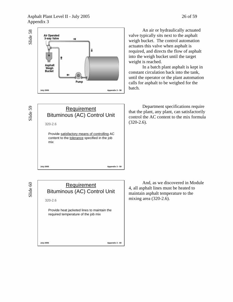
An air or hydraulically actuated valve typically sits next to the asphalt weigh bucket. The control automation actuates this valve when asphalt is required, and directs the flow of asphalt into the weigh bucket until the target weight is reached. In a batch plant asphalt is kept in constant circulation back into the tank, until the operator or the plant automation calls for asphalt to be weighed for the batch.
Slid
e 59
July 2005 Appendix 3 - 59
RequirementBituminous (AC) Control Unit
320-2.6
Provide satisfactory means of controlling AC content to the tolerance specified in the job mix
Department specifications require that the plant, any plant, can satisfactorily control the AC content to the mix formula (320-2.6).
Slid
e 60
July 2005 Appendix 3 - 60
RequirementBituminous (AC) Control Unit
320-2.6
Provide heat jacketed lines to maintain the required temperature of the job mix
And, as we discovered in Module 4, all asphalt lines must be heated to maintain asphalt temperature to the mixing area (320-2.6).
Asphalt Plant Level II - July 2005 27 of 59 Appendix 3
Slid
e 61
July 2005 Appendix 3 - 61
RequirementBatch Plant Batch Scales
320-2.2 Electronic Weigh Systems
Must be calibrated every six months by registered scale technician (to Florida Dept of Agriculture Bureau of Weights and Measures accuracy requirements)
(this also applies to asphalt weigh bucket)
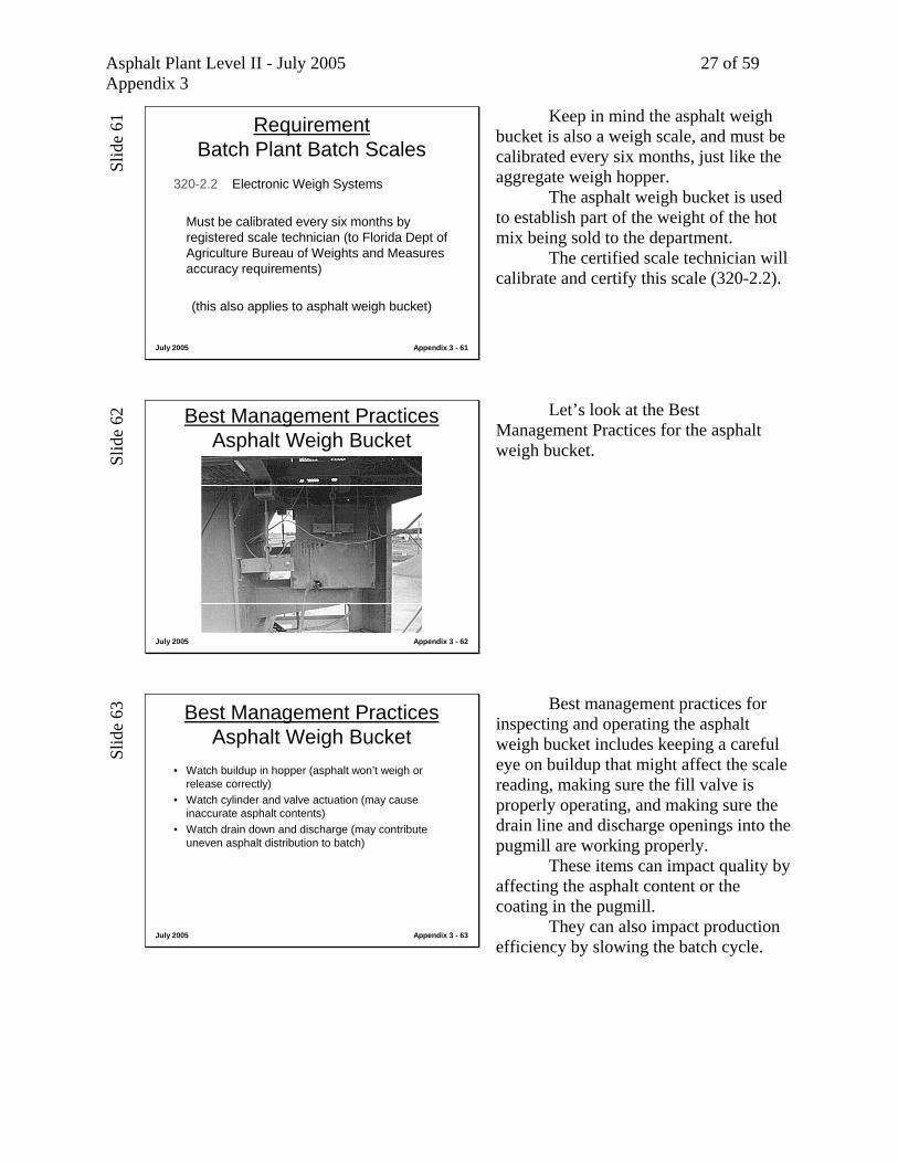
Keep in mind the asphalt weigh bucket is also a weigh scale, and must be calibrated every six months, just like the aggregate weigh hopper. The asphalt weigh bucket is used to establish part of the weight of the hot mix being sold to the department. The certified scale technician will calibrate and certify this scale (320-2.2).
Slid
e 62
July 2005 Appendix 3 - 62
Best Management PracticesAsphalt Weigh Bucket
Let’s look at the Best Management Practices for the asphalt weigh bucket.
Slid
e 63
July 2005 Appendix 3 - 63
Best Management PracticesAsphalt Weigh Bucket
• Watch buildup in hopper (asphalt won’t weigh or release correctly)
• Watch cylinder and valve actuation (may cause inaccurate asphalt contents)
• Watch drain down and discharge (may contribute uneven asphalt distribution to batch)
Best management practices for inspecting and operating the asphalt weigh bucket includes keeping a careful eye on buildup that might affect the scale reading, making sure the fill valve is properly operating, and making sure the drain line and discharge openings into the pugmill are working properly. These items can impact quality by affecting the asphalt content or the coating in the pugmill. They can also impact production efficiency by slowing the batch cycle.
Asphalt Plant Level II - July 2005 28 of 59 Appendix 3
Slid
e 64
July 2005 Appendix 3 - 64
Class Discussion
• The asphalt bucket is taking longer than normal to empty, but it is still within acceptable cycle times for the contractor.
• The mix seems to have a higher asphalt content on one side of the truck than the other. Plant QC spot checks have confirmed this.
(What could be happening?)(Where might we go to look?)
Let’s look at this theoretical situation. Assume the operator and Engineer notice that the asphalt weigh bucket is taking longer than usual to drain, but the batch cycle times have not had to be lengthened beyond the 35 second minimum. Of more concern to everyone is that the mix seems to have a higher asphalt content on one side of the truck than the other. Spot checks by the plant QC staff confirm this, and they’re worried. What could be happening? Where might we go to look?
Slid
e 65
July 2005 Appendix 3 - 65
Class Discussion
• The asphalt weight indicator doesn’t go back to zero during production. The operator keeps having to zero the instrument.
• The extractions are OK on tests, but the site Engineer is getting nervous. So is the contractor’s QC person. The Engineer is contemplating asking for a scale calibration check.
(What could be happening?)(Where might we go to look?)
Let’s consider a situation where the asphalt weight indicator is malfunctioning in some way. The unit won’t go back to zero each time. It seems to accumulate weight. The operator is allowing for extra drain down time, then re-zeros the instrument once it stabilizes between batches. The extractions and asphalt content are OK, but the Engineer and the contractors QC person are getting nervous. The Engineer is contemplating asking for a scale check to bring this to some sort of resolution. He knows he can ask for one whenever he suspect’s there is a problem (320-3.2.1 and 2). What could be happening? Where might we go to look?
Asphalt Plant Level II - July 2005 29 of 59 Appendix 3
Slid
e 66
July 2005 Appendix 3 - 66
Baghouse Dust ReturnBatch Plant
Dust is typically returned to the No.1 “fines” bin.
Typical systems:
• Screw conveyor to elevator• Pneumatically to fines bin
If the mix formula allows, baghouse fines are typically returned in a batch plant directly to the No. 1 or “fines” bin, either with a screw conveyor to the hot stone elevator or pneumatically directly to the “fines” bin.
Slid
e 67
July 2005 Appendix 3 - 67
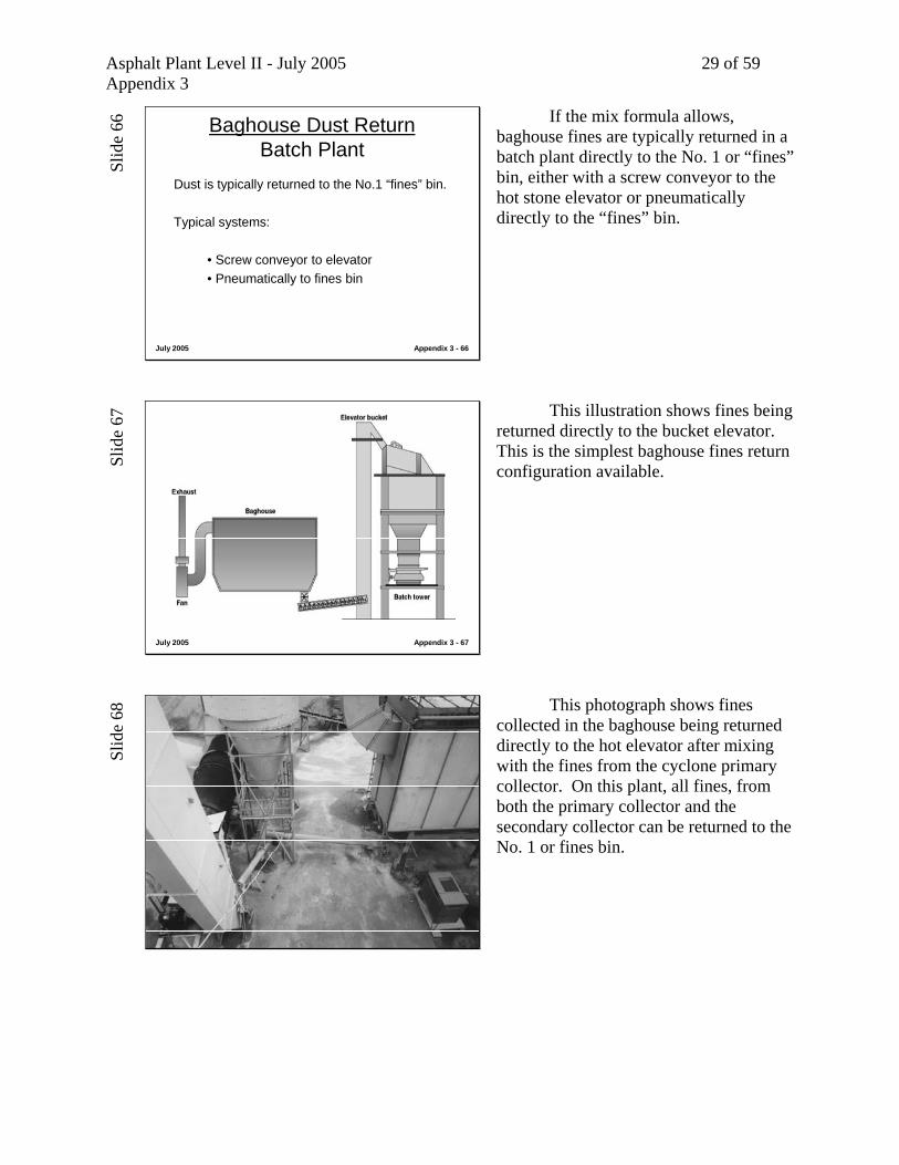
This illustration shows fines being returned directly to the bucket elevator. This is the simplest baghouse fines return configuration available.
Slid
e 68
July 2005 Appendix 3 - 68
This photograph shows fines collected in the baghouse being returned directly to the hot elevator after mixing with the fines from the cyclone primary collector. On this plant, all fines, from both the primary collector and the secondary collector can be returned to the No. 1 or fines bin.
Asphalt Plant Level II - July 2005 30 of 59 Appendix 3
Slid
e 69
July 2005 Appendix 3 - 69
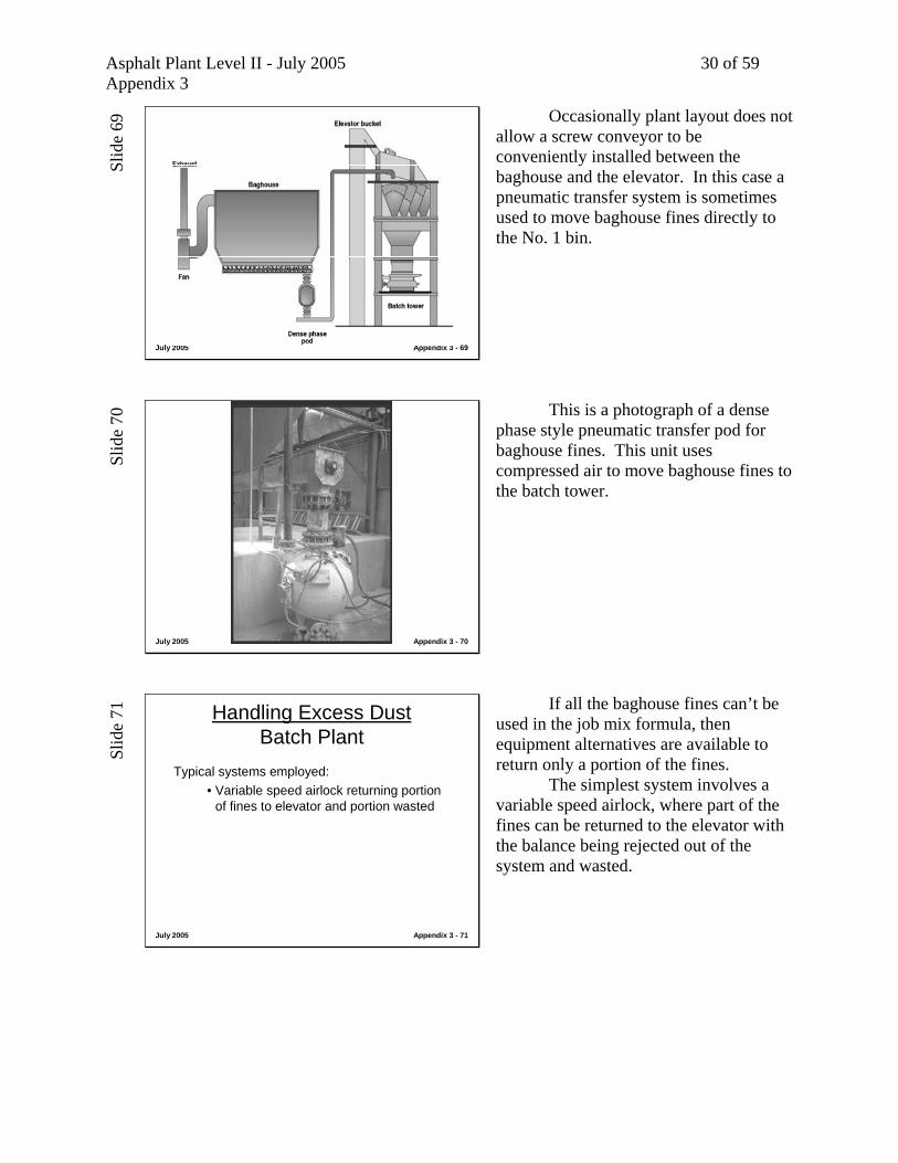
Occasionally plant layout does not allow a screw conveyor to be conveniently installed between the baghouse and the elevator. In this case a pneumatic transfer system is sometimes used to move baghouse fines directly to the No. 1 bin.
Slid
e 70
July 2005 Appendix 3 - 70
This is a photograph of a dense phase style pneumatic transfer pod for baghouse fines. This unit uses compressed air to move baghouse fines to the batch tower.
Slid
e 71
July 2005 Appendix 3 - 71
Handling Excess Dust Batch Plant
Typical systems employed:• Variable speed airlock returning portion
of fines to elevator and portion wasted
If all the baghouse fines can’t be used in the job mix formula, then equipment alternatives are available to return only a portion of the fines. The simplest system involves a variable speed airlock, where part of the fines can be returned to the elevator with the balance being rejected out of the system and wasted.
Asphalt Plant Level II - July 2005 31 of 59 Appendix 3
Slid
e 72
July 2005 Appendix 3 - 72
This photograph shows a system where a variable speed airlock allows the producer to return only a portion of the fines to the hot stone elevator in a batch plant. By monitoring the gradation of the fines bin, and changing the speed of the airlock, a smaller amount or larger amount of fines can be directed to the fines bin. The operator will establish a speed setting for the airlock for each production rate of each mix type.
Slid
e 73
July 2005 Appendix 3 - 73
Handling Excess Dust Batch Plant
Typical systems employed:• Fines transfer to silo, with screw
conveyor feed to weigh hopper
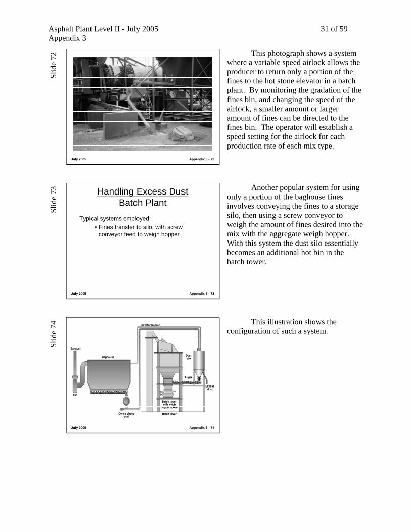
Another popular system for using only a portion of the baghouse fines involves conveying the fines to a storage silo, then using a screw conveyor to weigh the amount of fines desired into the mix with the aggregate weigh hopper. With this system the dust silo essentially becomes an additional hot bin in the batch tower.
Slid
e 74
July 2005 Appendix 3 - 74
This illustration shows the configuration of such a system.

Asphalt Plant Level II - July 2005 32 of 59 Appendix 3
Slid
e 75
July 2005 Appendix 3 - 75
This photograph shows a baghouse fines silo installed on structural legs next to the batch tower. Fines are returned to the weigh hopper by a screw conveyor.
Slid
e 76
July 2005 Appendix 3 - 76
Handling Excess Dust Batch Plant
Typical systems employed:• Fines transfer to silo, with pneumatic
transfer system directly to weigh hopper or pugmill
Another alternative is to transfer the fines into a silo, but use a pneumatic transfer system to move the fines to the weigh hopper or pugmill. By using an air conveying system, the silo can be placed anywhere in the plant layout. Additional flexibility is possible by suspending the dust pod on load cells and weighing the fines as an ingredient in the batch.
Slid
e 77
July 2005 Appendix 3 - 77
This illustration shows a typical system using a pneumatic transfer system and weigh hopper for metering the dust back in the mix.

Asphalt Plant Level II - July 2005 33 of 59 Appendix 3
Slid
e 78
July 2005 Appendix 3 - 78
Baghouse fines to silopneumatically, withweigh pod below silo, and pneumatic systemdirectly to pugmill
This is a photograph of a dense phase style transfer pod. Fines are first blown to the silo, then a fines pod “weighs” the required fines and transfers the required fines directly to the pugmill.
Slid
e 79
July 2005 Appendix 3 - 79
This plant has a fines silo located next to the tower.
Slid
e 80
July 2005 Appendix 3 - 80
Fines from the silo travel up a bucket elevator and are deposited into a surge pod, which feeds this weigh pod positioned on the side of the plant. After the required fines are weighed, the screw conveyor conveys the baghouse fines directly to the mixer. You can see that there are several different fines configurations available for metering only part of the fines back to the mix in a batch plant.
Asphalt Plant Level II - July 2005 34 of 59 Appendix 3
Slid
e 81
July 2005 Appendix 3 - 81
Hydrated LimeFC-5 Open Graded Friction
Courses
(GRANITE Aggregates)
Hydrated lime is used for stripping control on granite type aggregates for 337 FC-5 Friction Course Mixes.
Slid
e 82
July 2005 Appendix 3 - 82
RequirementHydrated lime for 337 “FC 5” mixes
337-9.2 All Plants • Separate feed system• Accurately proportioned• Coat the aggregate before the AC is injected• Must not be entrained in the air stream• Interlock the proportioning device• ± 10 % accuracy• No - flow = plant shutdown
There are several requirements for adding hydrating lime in the plant process for all plants (320-9.2). They include: Separate feed system Accurately proportioned Coat the aggregate before the AC is injected Must not be entrained in the air stream Interlock the proportioning device ± 10 % accuracy No - flow = plant shutdown
Slid
e 83
July 2005 Appendix 3 - 83
RequirementHydrated lime for 337 “FC 5” mixes
337-9.2 Two equipment methods
• Method (A) - dry• Method (B) - wet
(wet method covered in Module 3)
There are two equipment alternatives: the dry method A, and the wet method B. The wet method was discussed in Module 3 and is used when aggregate is going to be treated with hydrated lime prior to drying the aggregate. In this module we will discuss the dry method A.

Asphalt Plant Level II - July 2005 35 of 59 Appendix 3
Slid
e 84
July 2005 Appendix 3 - 84
RequirementHydrated lime for 337 “FC 5” mixes
337-9.2.1 Method A - dry - batch plant
• Add in weigh hopper or as the engineer approves• Increase the dry mix cycle 8-12 seconds or and the
engineer approves• Must be uniformly distributed before the AC is
injected
The dry method for a batch plant (337-9.2.1) requires the hydrated lime be introduced into the weigh hopper or as the Engineer approves. An acceptable alternative approach might weigh the lime in its own weigh hopper, then drop it into the pugmill. Batch automation is typically designed for three batch scales. There are other methods, however that work. The dry mix cycle must be increased 8-12 minutes, or based on the Engineer’s judgment. The lime must be uniformly distributed before the AC is injected.
Slid
e 85
July 2005 Appendix 3 - 85
Insert photograph of lime system on batch plant in Florida…..or two.
Slid
e 86
July 2005 Appendix 3 - 86
Using Fiber Additives
Fibers are used in 337 “FC-5” Open Graded Friction Course mixes
Fibers are used in open-graded 337, FC-5 Friction Coarse mixes. Fibers are used to help keep the asphalt in suspension between the aggregate particles in these coarse mixes to enhance their field performance.
Asphalt Plant Level II - July 2005 36 of 59 Appendix 3
Slid
e 87
July 2005 Appendix 3 - 87
RequirementFiber systems for 337 “FC-5” mixes
337-9.1 All plants• Separate feed system• Accurately proportion• Interlock to aggregate quantity• ± 10 % accuracy• No-flow = plant shutdown
The fiber systems on all plants are required to be separate from other feed ingredients, be interlocked to the aggregate quantity, adequately proportion to the aggregate quantity, be interlocked for plant shutdown on no-flow conditions, and be accurate to ± 10% (337-9.1).
Slid
e 88
July 2005 Appendix 3 - 88
RequirementFiber systems for 337 “FC-5” mixes
337-9.1 Batch plants
• Add fiber to weigh hopper or as engineer approves
• Increase dry mix cycle 8-12 seconds or as engineer approves
• Fibers must be uniformly distributed before AC is injected
Specifications (337-9.1) require fibers to be introduced into the weigh hopper, or by other methods that might be approved by the Engineer. One method might be to weigh the fibers in their own hopper and convey them directly into the pugmill for the dry mix cycle. Dry mix cycle times must be increased by 8-12 seconds, unless the Engineer feels a different cycle time is required or sufficient. And fibers must be uniformly distributed before the AC is injected. Note that different types of fibers may be handled differently.
Slid
e 89
July 2005 Appendix 3 - 89
Fiber Injection System Works on Drum or Batch Plant
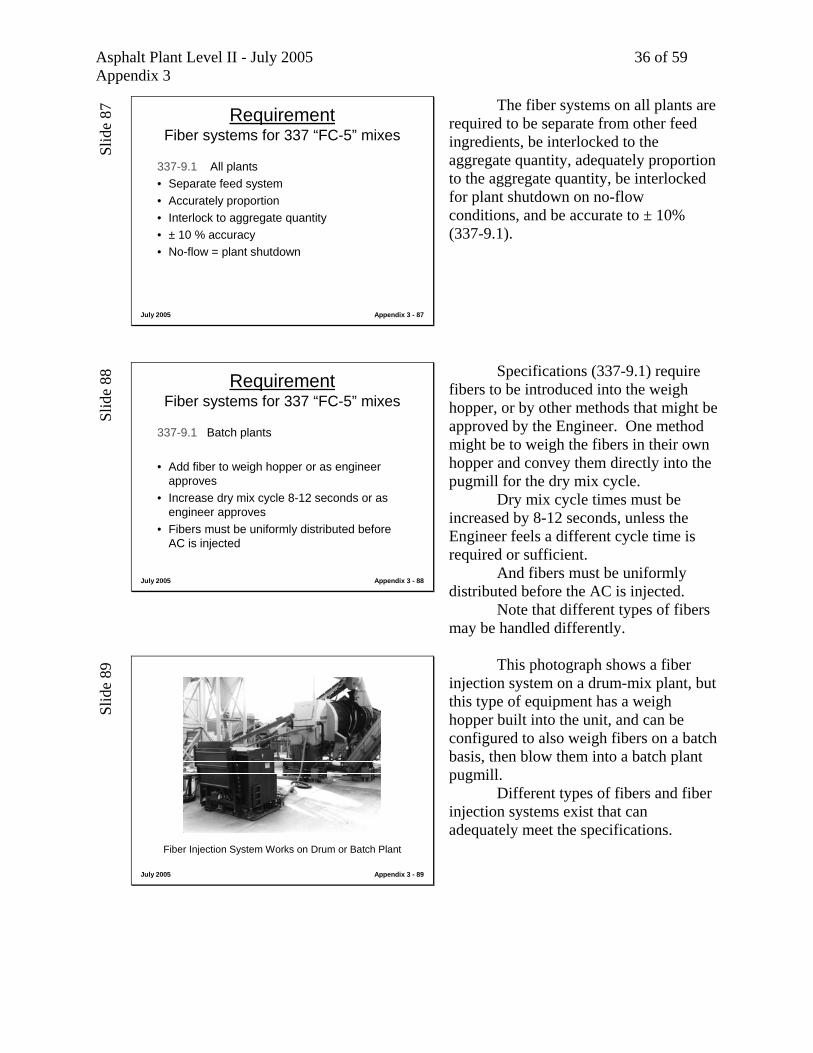
This photograph shows a fiber injection system on a drum-mix plant, but this type of equipment has a weigh hopper built into the unit, and can be configured to also weigh fibers on a batch basis, then blow them into a batch plant pugmill. Different types of fibers and fiber injection systems exist that can adequately meet the specifications.
Asphalt Plant Level II - July 2005 37 of 59 Appendix 3
Slid
e 90
July 2005 Appendix 3 - 90
Pugmill
The pugmill is the last equipment group in the batch tower. It is located below the aggregate weigh hopper and the asphalt weigh bucket.
Slid
e 91
July 2005 Appendix 3 - 91
Pugmill(dry mix cycle, wet mix cycle)
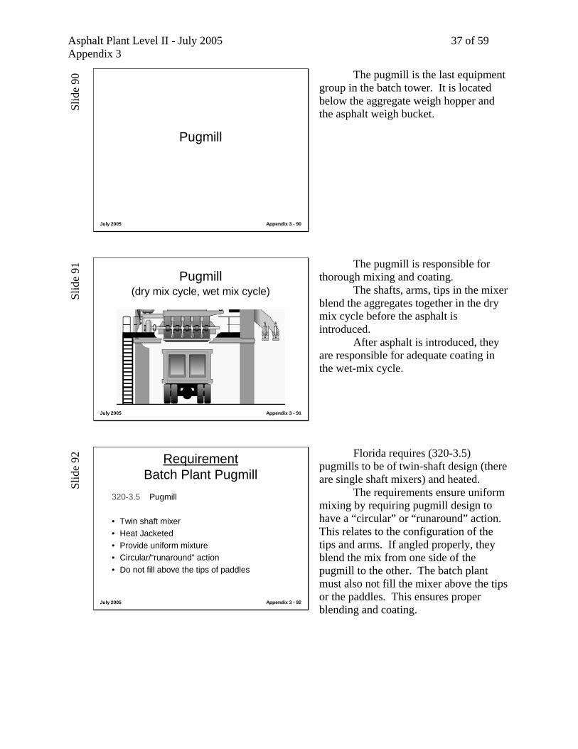
The pugmill is responsible for thorough mixing and coating. The shafts, arms, tips in the mixer blend the aggregates together in the dry mix cycle before the asphalt is introduced. After asphalt is introduced, they are responsible for adequate coating in the wet-mix cycle.
Slid
e 92
July 2005 Appendix 3 - 92
RequirementBatch Plant Pugmill
320-3.5 Pugmill
• Twin shaft mixer• Heat Jacketed• Provide uniform mixture• Circular/“runaround” action• Do not fill above the tips of paddles
Florida requires (320-3.5) pugmills to be of twin-shaft design (there are single shaft mixers) and heated. The requirements ensure uniform mixing by requiring pugmill design to have a “circular” or “runaround” action. This relates to the configuration of the tips and arms. If angled properly, they blend the mix from one side of the pugmill to the other. The batch plant must also not fill the mixer above the tips or the paddles. This ensures proper blending and coating.
Asphalt Plant Level II - July 2005 38 of 59 Appendix 3
Slid
e 93
July 2005 Appendix 3 - 93
Live Zone in Pugmill
Livezone
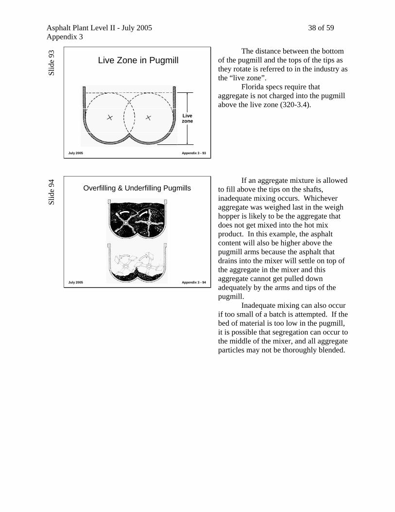
The distance between the bottom of the pugmill and the tops of the tips as they rotate is referred to in the industry as the “live zone”. Florida specs require that aggregate is not charged into the pugmill above the live zone (320-3.4).
Slid
e 94
July 2005 Appendix 3 - 94
Overfilling & Underfilling Pugmills If an aggregate mixture is allowed to fill above the tips on the shafts, inadequate mixing occurs. Whichever aggregate was weighed last in the weigh hopper is likely to be the aggregate that does not get mixed into the hot mix product. In this example, the asphalt content will also be higher above the pugmill arms because the asphalt that drains into the mixer will settle on top of the aggregate in the mixer and this aggregate cannot get pulled down adequately by the arms and tips of the pugmill. Inadequate mixing can also occur if too small of a batch is attempted. If the bed of material is too low in the pugmill, it is possible that segregation can occur to the middle of the mixer, and all aggregate particles may not be thoroughly blended.

Asphalt Plant Level II - July 2005 39 of 59 Appendix 3
Slid
e 95
July 2005 Appendix 3 - 95
RequirementPugmills
320-3.5
1 inch (25 mm) maximum clearance, tips to liners.
Specs call for a 1” maximum clearance, tips to liners. This is to ensure that all aggregate materials are thoroughly blended. If too large a gap is allowed to exist, then some aggregate particles cannot be picked up by the tips and blended with the others (320-3.5).
Slid
e 96
July 2005 Appendix 3 - 96
RequirementPugmills
320-3.5
If an additional 3/4 inch (20 mm) wear, replace or restore back to 1 inch (25 mm) clearance
320-3.5 requires that in addition to the initial clearance, when the tips wear to an additional 3/4” clearance, they must be replaced or adjusted out to close the gap created by the wear. The same logic for adequate mixing prevails as logic to the specification.
Slid
e 97
July 2005 Appendix 3 - 97
Inside of Pugmill This photograph shows the insides of a typical pugmill or mixer. The tips and liners are new. Notice the configuration of the arms and tips. Notice the clearance between the tips and liners. This is what ensures adequate mixing.

Asphalt Plant Level II - July 2005 40 of 59 Appendix 3
Slid
e 98
July 2005 Appendix 3 - 98
RequirementBatch Plant Pugmill
320-3.6 Mixer Timing
• Lockable for mixing time• “Positive” means of adjusting times
Specifications also require that the mixer timing is lockable for the cycle times, and the adjustment mechanism is “positive” (320-3.6). This means that the department is looking for a discreet and definite way to adjust the cycle times. Most plants have a thumbwheel timer, rotary timer, or computer field where dry mix and wet mix cycle times can be specifically set. Most automation has a lockable switch to meet the lockable part of the spec. This is a common feature on most batch automation, because this “positive adjustment” and “lockable” spec is common in other states.
Slid
e 99
July 2005 Appendix 3 - 99
RequirementBatch Plant Mixing
330-6.1.3
Mixing time requirements start when asphalt and aggregate are both in mixer.
In Florida, mixing time requirements start when the asphalt and aggregate are both in the mixer (330-6.1.3). This, of course, refers to the wet mix cycle. There is no requirement for dry mix cycle time, although one is expected and implied in the 337 specs, because when lime or fibers are added it is expected to be increased by 8-12 seconds.
Slid
e 10
0
July 2005 Appendix 3 - 100
RequirementBatch Plant Mixing
330-6.1.2 and 330-6.1.3
Mix until thoroughly coated as directed by the Engineer (at least 35 seconds)
The mixing time, or wet mix cycle, is to be set by the Engineer in order to perform adequate mixing, but must be at least 35 seconds (330-6.1.2 and 6.1.3).
Asphalt Plant Level II - July 2005 41 of 59 Appendix 3
Slid
e 10
1
July 2005 Appendix 3 - 101
Best Management PracticesPugmill
Let’s look at the Best Management Practices for the pugmill.
Slid
e 10
2
July 2005 Appendix 3 - 102
Best Management PracticesPugmill
• Routinely inspect tips, liners for clearance and missing parts (affects coating and mixing)
• Make sure discharge gates properly functioning and fit (eliminates mess and losing aggregates on charging mixer)
• Monitor batch weights to not charging above live zone (affects coating and mixing)
(items affect mixing and coating)
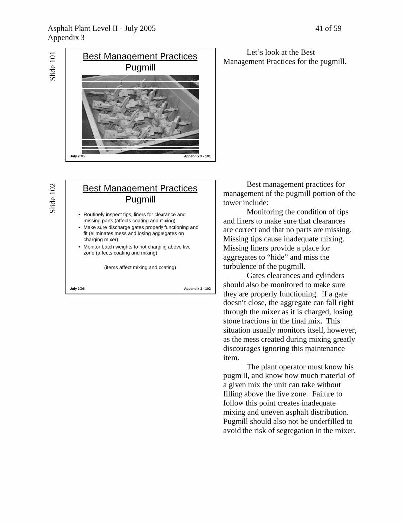
Best management practices for management of the pugmill portion of the tower include: Monitoring the condition of tips and liners to make sure that clearances are correct and that no parts are missing. Missing tips cause inadequate mixing. Missing liners provide a place for aggregates to “hide” and miss the turbulence of the pugmill. Gates clearances and cylinders should also be monitored to make sure they are properly functioning. If a gate doesn’t close, the aggregate can fall right through the mixer as it is charged, losing stone fractions in the final mix. This situation usually monitors itself, however, as the mess created during mixing greatly discourages ignoring this maintenance item. The plant operator must know his pugmill, and know how much material of a given mix the unit can take without filling above the live zone. Failure to follow this point creates inadequate mixing and uneven asphalt distribution. Pugmill should also not be underfilled to avoid the risk of segregation in the mixer.
Asphalt Plant Level II - July 2005 42 of 59 Appendix 3
Slid
e 10
3
July 2005 Appendix 3 - 103
Class Discussion
• Operator switching between fine and coarse mixes. • Fine mix being layed in thin lift.• Large stones keep showing up in mat.
(What could be happening?)(Where might we go to look?)
Let’s look at this theoretical situation. The operator is switching back and forth between coarse and fine mixes. The crew laying the fine mix keeps finding large stones in the mat. What could be happening? Where might we go to look?
Slid
e 10
4
July 2005 Appendix 3 - 104
Control Automation
Virtually every plant in the field has some sort of automation.
Slid
e 10
5
July 2005 Appendix 3 - 105
Pre-Computerized, Electro-Mechanical Batch Automation
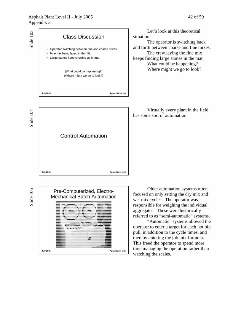
Older automation systems often focused on only setting the dry mix and wet mix cycles. The operator was responsible for weighing the individual aggregates. These were historically referred to as “semi-automatic” systems. “Automatic” systems allowed the operator to enter a target for each hot bin pull, in addition to the cycle times, and thereby entering the job mix formula. This freed the operator to spend more time managing the operation rather than watching the scales.

Asphalt Plant Level II - July 2005 43 of 59 Appendix 3
Slid
e 10
6
July 2005 Appendix 3 - 106
Computerized Batch and Silo Loadout Automation
Modern, computerized batch systems allow the operator to enter formulas into stored memory for later recall, cue up trucks for different mix formulas and batch sizes, watch target weight vs. actual weight tolerances, print individual weights on batch tickets, record the customer/project/mix number, provide accumulated tonnages for the job to-day and to-date, and even provide directions to the job site. Batch plants with silos often have two systems, as shown here, with shared database information. Regardless of whether the mix is loaded from the silo or the batch tower, the project totals are kept current.
Slid
e 10
7
July 2005 Appendix 3 - 107
Screen from Computerized Batch Automation
This photograph shows a typical batch automation screen. Notice the “required” and “actual” weight columns, and the “difference” column expressed as a percentage. Batch automation typically controls the mix formula, the quantity mixed, the dry and wet mix cycle times. They do not control the temperature or the cold feed.
Slid
e 10
8
July 2005 Appendix 3 - 108
“Table Top” Computerized Batch Automation
With computer automation becoming more compact, it is easy to automate any batch plant as long as there is room on a desk somewhere to place a computer. This table-top model has all the features of a full console unit.
Asphalt Plant Level II - July 2005 44 of 59 Appendix 3
Slid
e 10
9
July 2005 Appendix 3 - 109
RequirementAutomatic Ticket Printout
• Ticketing requirements will be covered inModule 8 with silo loadout
• Silo ticketing requirements same as automatic ticket from tower
• And allow batch weights to print either individual or cumulative weights of aggregate and asphalt (320-2.3). Testing procedure for testing asphalt content
Ticketing requirements will be covered in Module 8. They are the same as with silo loadout. Batch weights can be printed either as individual or cumulative weights for the aggregate and the asphalt. Testing procedures covered in Module 10 will determine asphalt content and extracted gradations, so this individual information is not required.
Slid
e 11
0
Using RAP in a Batch Plant
The following section reviews the different methods of using RAP in a batch plant.
Asphalt Plant Level II - July 2005 45 of 59 Appendix 3
Slid
e 11
1
July 2005 Appendix 3 - 111
Using RAP in a Batch Plant
Two methods typical:
• Weigh Hopper / Weigh Batcher• Bucket Elevator
(both rely on conductive heat transfer)
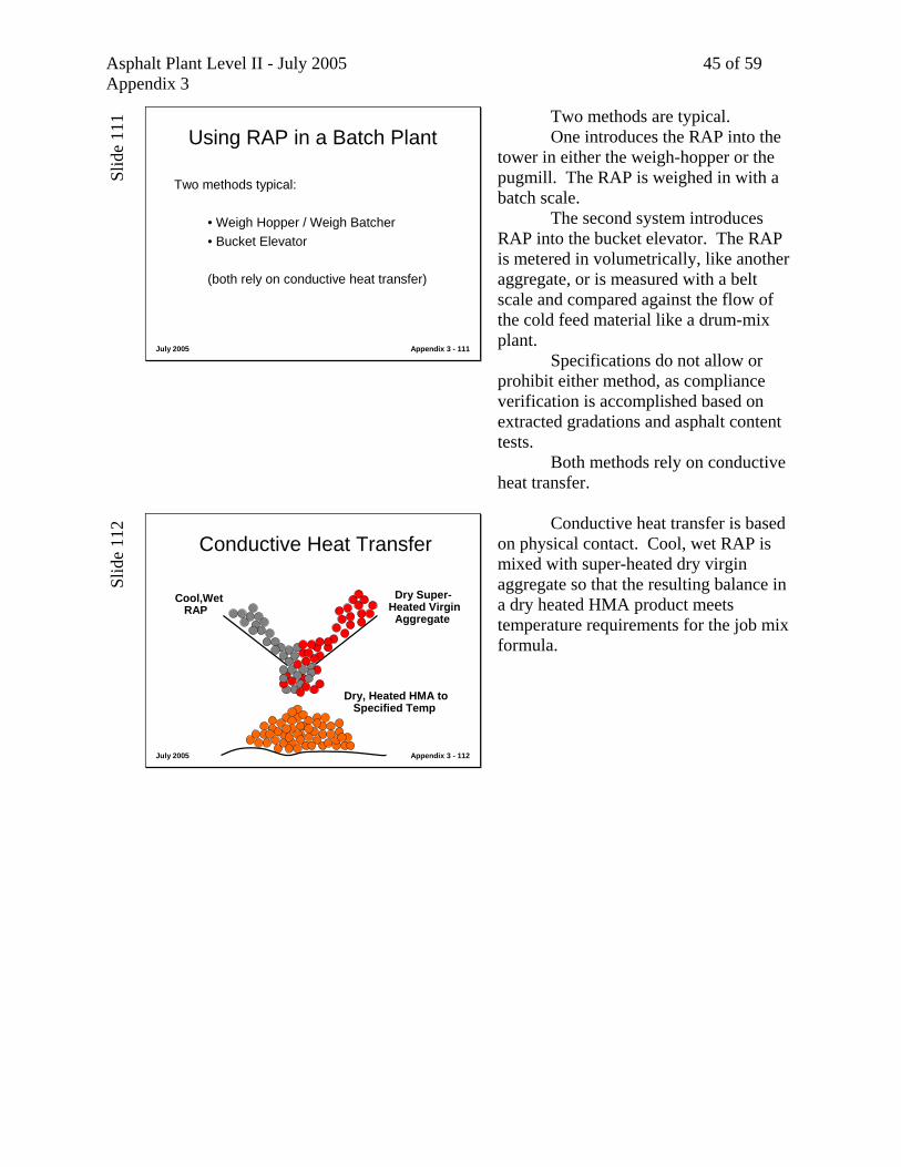
Two methods are typical. One introduces the RAP into the tower in either the weigh-hopper or the pugmill. The RAP is weighed in with a batch scale. The second system introduces RAP into the bucket elevator. The RAP is metered in volumetrically, like another aggregate, or is measured with a belt scale and compared against the flow of the cold feed material like a drum-mix plant. Specifications do not allow or prohibit either method, as compliance verification is accomplished based on extracted gradations and asphalt content tests. Both methods rely on conductive heat transfer.
Slid
e 11
2
July 2005 Appendix 3 - 112
Conductive Heat Transfer
Dry Super-Heated Virgin
Aggregate
Cool,WetRAP
Dry, Heated HMA to Specified Temp
Conductive heat transfer is based on physical contact. Cool, wet RAP is mixed with super-heated dry virgin aggregate so that the resulting balance in a dry heated HMA product meets temperature requirements for the job mix formula.
Asphalt Plant Level II - July 2005 46 of 59 Appendix 3
Slid
e 11
3
July 2005 Appendix 3 - 113
“Weigh Box” Batch Facility Recycling Technique
RAP Bin Batch Steam Release to Emission Control Equipment
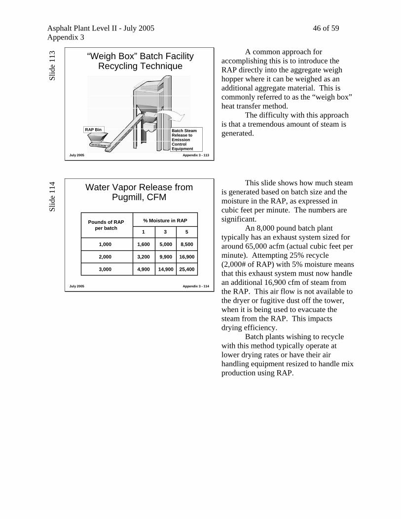
A common approach for accomplishing this is to introduce the RAP directly into the aggregate weigh hopper where it can be weighed as an additional aggregate material. This is commonly referred to as the “weigh box” heat transfer method. The difficulty with this approach is that a tremendous amount of steam is generated.
Slid
e 11
4
July 2005 Appendix 3 - 114
Water Vapor Release from Pugmill, CFM
Pounds of RAPper batch
% Moisture in RAP
1 3 5
1,000
2,000
3,000
1,600 5,000 8,500
3,200 9,900 16,900
4,900 14,900 25,400
This slide shows how much steam is generated based on batch size and the moisture in the RAP, as expressed in cubic feet per minute. The numbers are significant. An 8,000 pound batch plant typically has an exhaust system sized for around 65,000 acfm (actual cubic feet per minute). Attempting 25% recycle (2,000# of RAP) with 5% moisture means that this exhaust system must now handle an additional 16,900 cfm of steam from the RAP. This air flow is not available to the dryer or fugitive dust off the tower, when it is being used to evacuate the steam from the RAP. This impacts drying efficiency. Batch plants wishing to recycle with this method typically operate at lower drying rates or have their air handling equipment resized to handle mix production using RAP.
Asphalt Plant Level II - July 2005 47 of 59 Appendix 3
Slid
e 11
5
July 2005 Appendix 3 - 115
Recycling with Batch Plant Req Virgin Agg Temp with 3% H20 in RAP
300350400450500550600650700
% RAP10 20 30 40 50
Agg
rega
te T
empe
ratu
re ºF
260 ºF280 ºF
Final Mix Temperature
315340
360 385445
475
535570
660705
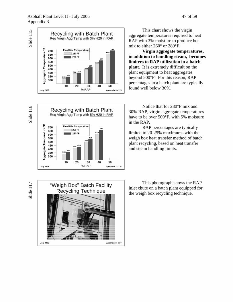
This chart shows the virgin aggregate temperatures required to heat RAP with 3% moisture to produce hot mix to either 260° or 280°F. Virgin aggregate temperatures, in addition to handling steam, becomes limiters to RAP utilization in a batch plant. It is extremely difficult on the plant equipment to heat aggregates beyond 500°F. For this reason, RAP percentages in a batch plant are typically found well below 30%.
Slid
e 11
6
July 2005 Appendix 3 - 116
Recycling with Batch Plant Req Virgin Agg Temp with 5% H20 in RAP
300350400450500550600650700
% RAP10 20 30 40 50
Agg
rega
te T
empe
ratu
re ºF
260 ºF280 ºF
Final Mix Temperature
335360
405 430
495525
610
645
Notice that for 280°F mix and 30% RAP, virgin aggregate temperatures have to be over 500°F, with 5% moisture in the RAP. RAP percentages are typically limited to 20-25% maximums with the weigh box heat transfer method of batch plant recycling, based on heat transfer and steam handling limits.
Slid
e 11
7
July 2005 Appendix 3 - 117
“Weigh Box” Batch Facility Recycling Technique
This photograph shows the RAP inlet chute on a batch plant equipped for the weigh box recycling technique.
Asphalt Plant Level II - July 2005 48 of 59 Appendix 3
Slid
e 11
8
July 2005 Appendix 3 - 118
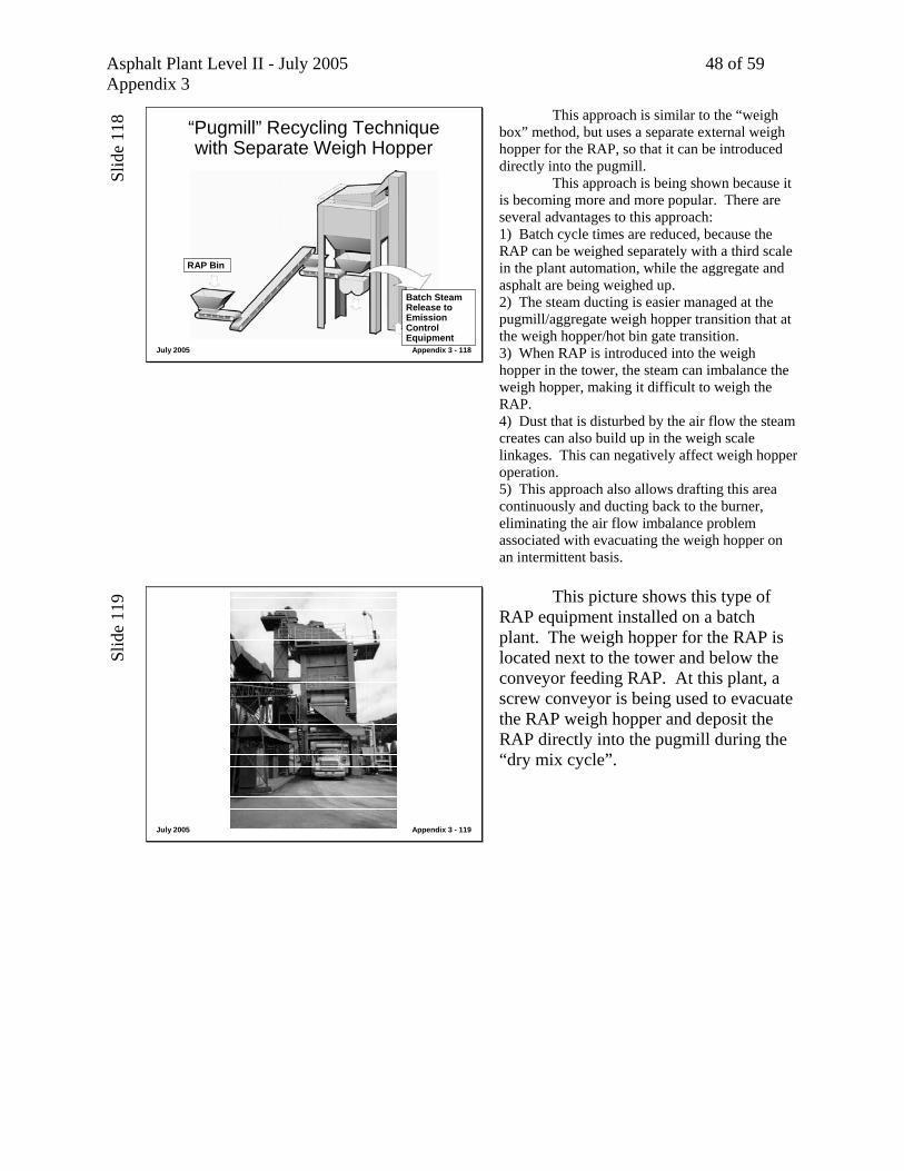
“Pugmill” Recycling Technique with Separate Weigh Hopper
RAP Bin
Batch Steam Release to Emission Control Equipment
This approach is similar to the “weigh box” method, but uses a separate external weigh hopper for the RAP, so that it can be introduced directly into the pugmill. This approach is being shown because it is becoming more and more popular. There are several advantages to this approach: 1) Batch cycle times are reduced, because the RAP can be weighed separately with a third scale in the plant automation, while the aggregate and asphalt are being weighed up. 2) The steam ducting is easier managed at the pugmill/aggregate weigh hopper transition that at the weigh hopper/hot bin gate transition. 3) When RAP is introduced into the weigh hopper in the tower, the steam can imbalance the weigh hopper, making it difficult to weigh the RAP. 4) Dust that is disturbed by the air flow the steam creates can also build up in the weigh scale linkages. This can negatively affect weigh hopper operation. 5) This approach also allows drafting this area continuously and ducting back to the burner, eliminating the air flow imbalance problem associated with evacuating the weigh hopper on an intermittent basis.
Slid
e 11
9
July 2005 Appendix 3 - 119
This picture shows this type of RAP equipment installed on a batch plant. The weigh hopper for the RAP is located next to the tower and below the conveyor feeding RAP. At this plant, a screw conveyor is being used to evacuate the RAP weigh hopper and deposit the RAP directly into the pugmill during the “dry mix cycle”.
Asphalt Plant Level II - July 2005 49 of 59 Appendix 3
Slid
e 12
0
July 2005 Appendix 3 - 120
A continuous draft is created at the weigh hopper pugmill transition through the use of a fan. This fan evacuates the steam that is generated during the dry mix cycle as RAP is introduced into the pugmill and directs the air into the dryer to be used in the drying and heating process.
Slid
e 12
1
July 2005 Appendix 3 - 121
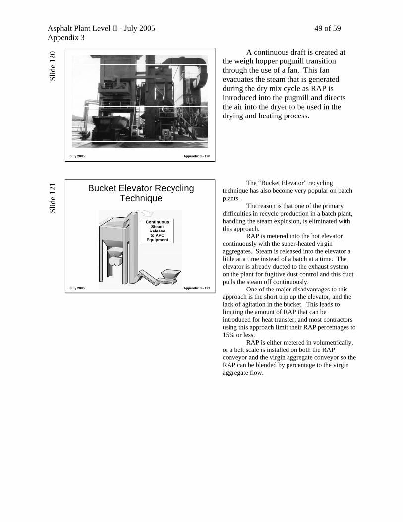
Bucket Elevator Recycling Technique
Continuous Steam
Releaseto APC
Equipment
The “Bucket Elevator” recycling technique has also become very popular on batch plants. The reason is that one of the primary difficulties in recycle production in a batch plant, handling the steam explosion, is eliminated with this approach. RAP is metered into the hot elevator continuously with the super-heated virgin aggregates. Steam is released into the elevator a little at a time instead of a batch at a time. The elevator is already ducted to the exhaust system on the plant for fugitive dust control and this duct pulls the steam off continuously. One of the major disadvantages to this approach is the short trip up the elevator, and the lack of agitation in the bucket. This leads to limiting the amount of RAP that can be introduced for heat transfer, and most contractors using this approach limit their RAP percentages to 15% or less. RAP is either metered in volumetrically, or a belt scale is installed on both the RAP conveyor and the virgin aggregate conveyor so the RAP can be blended by percentage to the virgin aggregate flow.
Asphalt Plant Level II - July 2005 50 of 59 Appendix 3
Slid
e 12
2
July 2005 Appendix 3 - 122
Conveyor Feeding RAP to Bucket Elevator
This is a photograph of a bucket elevator system installed for RAP on a batch plant.
Slid
e 12
3
July 2005 Appendix 3 - 123
Bucket Elevator Recycling Technique
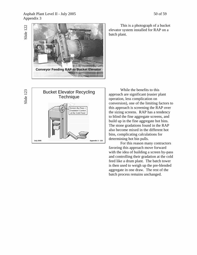
Screen By-Pass =Gradation Control at the Cold Feed
While the benefits to this approach are significant (easier plant operation, less complication on conversion), one of the limiting factors to this approach is screening the RAP over the sizing screens. RAP has a tendency to blind the fine aggregate screens, and build up in the fine aggregate hot bins. The stone gradations found in the RAP also become mixed in the different hot bins, complicating calculations for determining hot bin pulls. For this reason many contractors favoring this approach move forward with the idea of building a screen by-pass and controlling their gradation at the cold feed like a drum plant. The batch tower is then used to weigh up the pre-blended aggregate in one draw. The rest of the batch process remains unchanged.

Asphalt Plant Level II - July 2005 51 of 59 Appendix 3
Slid
e 12
4
July 2005 Appendix 3 - 124
“Bucket Elevator” Technique with Heat Transfer Chamber on Dryer
RAP
RAP Steam Release in
Dryer
Equipment is available to raise the RAP percentage using the bucket elevator method by introducing the RAP into the combustion area of the dryer. The steam released from the RAP is carried away in the dryer with the steam from the virgin aggregate, so the problems associated with handling steam are totally eliminated. The approach is introduced in the course because it allows an even higher RAP percentage, and is becoming more popular. The RAP is heated conductively not only with the superheated virgin aggregate, but with the conductive heat from the combustion area of the shell. RAP percentages of 30% are easily accomplished with this equipment approach, and fuel costs are reduced compared to other RAP methods.
Slid
e 12
5
July 2005 Appendix 3 - 125
Heat Transfer Chamber for RAP on Dryer
This is a photograph of a RAP heat transfer chamber on a batch plant dryer.

Asphalt Plant Level II - July 2005 52 of 59 Appendix 3
Slid
e 12
6
July 2005 Appendix 3 - 126
(Establishing Hot Bin Percentages and Weights for Production Requirements)
(See Appendix 3b for Proceduresand Sample Problems)
Calibration of Hot BinsBatch Plants
Prior to establishing the cold feed bin settings, one has to establish the individual hot bin weights or draws. This has historically been referred to as Hot Bin Calibration in the Department in Florida. This is first done by analyzing the individual gradations of the hot bins, and establishing the proper blends in percentages to meet the Job Mix Formula. The same type of “weighted average” blending procedure done during the Mix Design Stage and outlined in Module 3 is used. To see how this is specifically accomplished for hot bin percentages or “draws”, refer to Appendix 3b.
Slid
e 12
7
July 2005 Appendix 3 - 127
(Establishing Cold Feed Gate Openingsfor Production Requirements)
(See Appendix 3a for Proceduresand Sample Problems)
Calibration of Cold FeedBatch Plants
The next step is establishing the cold feed bin settings to meet the hot bin requirements. This has historically been referred to as the Cold Feed Bin Calibration process in the Department. The procedures for calibrating cold feed bins on a batch plant are outlined in Appendix 3a. This procedure assumes adjustment of the gate openings to regulate flow from each cold feed bin. Gates are adjusted to meet production requirements for the hot bins. This details the traditional approach to regulating cold feed flow. Most batch plants today, however, have variable speed belts on their cold feed bins, just like drum-mixer plants. Feeder speeds are adjusted to match hot bin requirements. To see how this is accomplished, refer to Module 3 or Module 7, both of which have explanations of how to calibrate cold feed bin feeders by regulating belt speed.

Asphalt Plant Level II - July 2005 53 of 59 Appendix 3
Slid
e 12
8
July 2005 Appendix 3 - 128
Batch Plant Inspection
The following summarizes batch plant inspection items, based on published specifications.
Slid
e 12
9
July 2005 Appendix 3 - 129
Batch Plant InspectionScreen Deck
• Capable of separating coarse and fine materials into specific sizes? (320-3.1)
• Capable of scalping off oversized materials. (320-3.1)and not re-using without re-processing? (330-5.7.1)
• Not exceeding capacity of screens? (330-5.7.2)• More than 10% +10 material in -10 bin? (320-5.7.2)
The following items relate to the screen deck. Capable of separating coarse and fine materials into specific sizes (320-3.1)? Capable of scalping off oversized materials (320-3.1), and not re-using without re-processing (330-5.7.1)? Not exceeding capacity of screens (330-5.7.2)? More than 10% +10 material in -10 bin (320-5.7.2)?
Slid
e 13
0
July 2005 Appendix 3 - 130
Batch Plant InspectionHot Storage Bins
• Divided compartments to keep fractions separate? (320-3.2)
• Equipped with overflow chutes? (320-3.2)• Proper sampling access? (320-3.3)• Wash graded hot bin samples or extracted gradations
accomplished prior to production? (334-4.3)
The following items relate to the hot storage bins. Divided compartments to keep fractions separate (320-3.2)? Equipped with overflow chutes (320-3.2)? Proper sampling access (320-3.3)? Wash graded hot bin samples or extracted gradations accomplished prior to production (334-4.3)?

Asphalt Plant Level II - July 2005 54 of 59 Appendix 3
Slid
e 13
1
July 2005 Appendix 3 - 131
Batch Plant InspectionAggregate Weigh Hopper
• Weigh hopper properly designed, free-moving, capable of handling full batch? (320-3.4)
• Calibrated within last six months? (320-2.2)• Accuracy being checked weekly? (320-2.2.4.2)
The following items relate to the weigh hopper. Weigh hopper properly designed, free-moving, capable of handling full batch (320-3.4)? Calibrated within last six months (320-2.2)? Accuracy being checked weekly (320-2.2.4.2)?
Slid
e 13
2
July 2005 Appendix 3 - 132
Batch Plant InspectionBituminous Control Unit
• Heated lines? (320-2.6)• Can control AC satisfactorily to job mix formula?
(320-2.6) (Mix testing procedures detailed in Module 10)
The following items relate to the bituminous control unit. Heated lines (320-2.6)? Can control AC satisfactorily to job mix formula (320-2.6)? (Mix testing procedures detailed in Module 10)
Asphalt Plant Level II - July 2005 55 of 59 Appendix 3
Slid
e 13
3
July 2005 Appendix 3 - 133
Batch Plant InspectionHydrated Lime - Dry Method
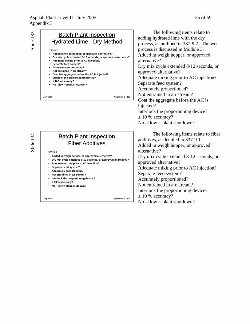
337-9.2• Added in weigh hopper, or approved alternative?• Dry mix cycle extended 8-12 seconds, or approved alternative?• Adequate mixing prior to AC injection?• Separate feed system?• Accurately proportioned?• Not entrained in air stream?• Coat the aggregate before the AC is injected?• Interlock the proportioning device?• ± 10 % accuracy?• No - flow = plant shutdown?
The following items relate to adding hydrated lime with the dry process, as outlined in 337-9.2. The wet process is discussed in Module 3. Added in weigh hopper, or approved alternative? Dry mix cycle extended 8-12 seconds, or approved alternative? Adequate mixing prior to AC injection? Separate feed system? Accurately proportioned? Not entrained in air stream? Coat the aggregate before the AC is injected? Interlock the proportioning device? ± 10 % accuracy? No - flow = plant shutdown?
Slid
e 13
4
July 2005 Appendix 3 - 134
Batch Plant InspectionFiber Additives
337-9.1• Added in weigh hopper, or approved alternative?• Dry mix cycle extended 8-12 seconds, or approved alternative?• Adequate mixing prior to AC injection?• Separate feed system?• Accurately proportioned?• Not entrained in air stream?• Interlock the proportioning device?• ± 10 % accuracy?• No - flow = plant shutdown?
The following items relate to fiber additives, as detailed in 337-9.1. Added in weigh hopper, or approved alternative? Dry mix cycle extended 8-12 seconds, or approved alternative? Adequate mixing prior to AC injection? Separate feed system? Accurately proportioned? Not entrained in air stream? Interlock the proportioning device? ± 10 % accuracy? No - flow = plant shutdown?

Asphalt Plant Level II - July 2005 56 of 59 Appendix 3
Slid
e 13
5
July 2005 Appendix 3 - 135
Quality Mgt in BP ProductionIf test results show…
Sl
ide
136
July 2005 Appendix 3 - 136
Quality Mgt in BP ProductionIf test results show…
Gradation Shift / Coarser (Aggregate), check…
Wrong mix formula (human error)Hole in screen Hole in screen exit chute (gradation shift coarser or finer based on screen chute angle)Gradation change in feed aggregates
Slid
e 13
7
July 2005 Appendix 3 - 137
Quality Mgt in BP ProductionIf test results show…
Gradation Shift / Finer (Aggregate), check …Wrong mix formula (human error)Flooded screen (high tph rate or one material)Blinded screen (plugged or material not drying)Hole in hot bin wallHole in screen exit chute (gradation shift coarser or finer based on screen chute angle)Gradation change in feed aggregates

Asphalt Plant Level II - July 2005 57 of 59 Appendix 3
Slid
e 13
8
July 2005 Appendix 3 - 138
Quality Mgt in BP ProductionIf test results show…
Gradation Shift / Finer (Dust), check …Wrong mix formula (human error)Dust slough in fines binFines bin stratification (vibration / idling)Lack of draft in dryer (retained fines in dryer feed to elevator vs. to baghouse and BH fines are being wasted or used partially) Malfunction dust return or additive (excess)Gradation change in feed aggregates
Sl
ide
139
July 2005 Appendix 3 - 139
Quality Mgt in BP ProductionIf test results show…
Gradation Shift / Coarser (Dust), check …Wrong mix formula (human error)Stratified segregation in fines binOver-draft in dryer (less fines in dryer feed to elevator vs. to baghouse and BH fines are being wasted or used partially ) Malfunction dust return or additive (reduced)Gradation change in feed aggregates
Slid
e 14
0
July 2005 Appendix 3 - 140
Quality Mgt in BP ProductionIf test results show…
Low Voids, check …Wrong mix formula (human error)“Dust slough” from fines binDust return / additive malfunctionHot bin stratification (vibration / idling)Lack of draft in dryer (retained fines in dryer feed to elevator vs. to baghouse and BH fines are being wasted or used partially) Gradation change in feed aggregates
Asphalt Plant Level II - July 2005 58 of 59 Appendix 3
Slid
e 14
1
July 2005 Appendix 3 - 141
Quality Mgt in BP ProductionIf test results show…
High Voids, check …Wrong mix formula (human error)Dust return / additive malfunctionOver-drafting dryer (fines to baghouse vs. retained in dryer feed to elevator and BH fines are being wasted or used partially)Hot bin stratification (vibration / idling)Gradation change in feed aggregates
Sl
ide
142
July 2005 Appendix 3 - 142
Quality Mgt in BP ProductionIf test results show…
AC Content High, check …Wrong mix formula (human error)Malfunction in weigh bucketMalfunctioning AC injection / coating & sample in rich side of batchMissing pugmill tips, inadequate mixing & sample in rich side of batchWeigh bucket out of calibrationAutomation error / consistently miss target
Slid
e 14
3
July 2005 Appendix 3 - 143
Quality Mgt in BP ProductionIf test results show…
AC Content Low, check …Wrong mix formula (human error)Malfunction in weigh bucketMalfunctioning AC injection / coating & sample in lean side of batchMissing pugmill tips, inadequate mixing & sample in lean side of batchWeigh bucket out of calibrationAutomation error / consistently miss target
Asphalt Plant Level II - July 2005 59 of 59 Appendix 3
Slid
e 14
4
July 2005 Appendix 3 - 144
Quality Mgt in BP ProductionIf test results show…
AC Content Varies, check …Malfunction in weigh bucketMalfunctioning AC injection / coating & sampling detects variation in homogeneityMissing pugmill tips, inadequate mixing & sampling detects variation in homogeneityAutomation error / inconsistency
Sl
ide
145
July 2005 Appendix 3 - 145
Quality Mgt in BP ProductionIf test results show…
Inadequate Coating, check …Wet mix cycle time too shortMissing pugmill tips / shanksClearance tips to liner (too great)Inadequate drying of aggregate“Dust slough” / “dry batch”
Slid
e 14
6
July 2005 Appendix 3 - 146
QUESTIONS ?