construction of submersible sewage pumping stations · construction of submersible sewage pumping...
TRANSCRIPT
STS402
Hunter Water Corporation A.B.N. 46 228 513 446
Standard Technical Specification for:
CONSTRUCTION OF SUBMERSIBLESEWAGE PUMPING STATIONS
This Standard Technical Specification was developed by Hunter Water to be used for the constructionand/or maintenance of water and/or sewerage works that are, or are to become, the property of HunterWater. It is intended that this Standard Technical Specification be used in conjunction with variousother standard and project specific drawings and design requirements as defined by Hunter Water foreach particular project.
Hunter Water does not consider this Standard Technical Specification suitable for use for any otherpurpose or in any other manner. Use of this Standard Technical Specification for any other purpose orin any other manner is wholly at the user's risk.
Hunter Water makes no representations or warranty that this Standard Technical Specification hasbeen prepared with reasonable care and does not assume a duty of care to any person using thisdocument for any purpose other than stated.
In the case of this document having been downloaded from Hunter Water's website;
- Hunter Water has no responsibility to inform you of any matter relating to the accuracy of thisStandard Technical Specification which is known to Hunter Water at the time of downloading orsubsequently comes to the attention of Hunter Water.
- This document is current at the date of downloading. Hunter Water may update this document at anytime.
Copyright in this document belongs to Hunter Water Corporation.

Hunter Water Corporation A.B.N. 46 228 513 446
STS402 September 2011
CONTENTS
1. GENERAL ...........................................................................................................11.1 Scope .............................................................................................................................. 11.2 Interpretation ................................................................................................................... 1
2. REFERENCED DOCUMENTS.............................................................................1
3. ORDER OF CONSTRUCTION.............................................................................3
4. MATERIALS ........................................................................................................34.1 General............................................................................................................................ 34.2 On-site Stockpiles ........................................................................................................... 34.3 Bedding Sand.................................................................................................................. 34.4 High Grade Compaction Sand ........................................................................................ 34.5 Select Fill......................................................................................................................... 34.6 Trench Fill ....................................................................................................................... 44.7 Cement Stabilised Trench Fill ......................................................................................... 44.8 Pipes and Fittings............................................................................................................ 44.9 Polyethylene Sleeving ..................................................................................................... 44.10 Geotextile Filter Fabric .................................................................................................... 44.11 Timber Piles .................................................................................................................... 44.12 Fasteners ........................................................................................................................ 44.13 Cement............................................................................................................................ 44.14 Concrete.......................................................................................................................... 54.15 Reinforcement................................................................................................................. 54.16 Appurtenances ................................................................................................................ 54.17 Knife Gate Valves............................................................................................................ 54.18 Equipment Number Labels.............................................................................................. 54.19 Metering Equipment ........................................................................................................ 64.20 Lock Barrels .................................................................................................................... 6
5. EXISTING SERVICES .........................................................................................65.1 Location of Services........................................................................................................ 65.2 Protection and Maintenance of Services......................................................................... 65.3 Repair of Services........................................................................................................... 6
6. CLEARING ..........................................................................................................6
7. EXCAVATION......................................................................................................67.1 Limits of Excavation ........................................................................................................ 67.2 Improved Surfaces .......................................................................................................... 77.3 Drainage and Dewatering................................................................................................ 77.4 Foundations and Foundation Stabilisation ...................................................................... 77.5 Extra Depth Excavation................................................................................................... 77.6 Surplus Excavated Material............................................................................................. 8
8. PIPE BEDDING, LAYING, JOINTING AND BACKFILLING ................................88.1 General............................................................................................................................ 88.2 Pipework Surface Coating............................................................................................... 8
9. BACKFILLING OF STRUCTURES......................................................................89.1 General............................................................................................................................ 89.2 Compaction and Density Testing .................................................................................... 9
10. CONCRETE.........................................................................................................910.1 General............................................................................................................................ 910.2 Identification Certificate................................................................................................. 1010.3 Expansion and Contraction Joints................................................................................. 1010.4 Blockouts and Cored Holes........................................................................................... 1010.5 Cast In Items ................................................................................................................. 1110.6 Specific Requirements .................................................................................................. 1110.7 Unformed Surfaces Finish ............................................................................................ 1210.8 Topping and Benching .................................................................................................. 1210.9 Concrete Repairs .......................................................................................................... 1210.10 Testing .......................................................................................................................... 12

Construction of Submersible Sewage Pumping Stations
September 2011 STS402
11. PUMPING STATION WET WELL......................................................................1311.1 Flotation......................................................................................................................... 1311.2 Corrosion Protection ........................................................................................................ 1311.3 Precast Concrete Units ................................................................................................. 1311.4 Tolerances..................................................................................................................... 1311.5 Blockouts....................................................................................................................... 1311.6 Cast Insitu Plug ............................................................................................................. 13
12. WATER SUPPLY TO PUMPING STATION....................................................... 1312.1 General.......................................................................................................................... 1312.2 Materials ........................................................................................................................ 1412.3 Installation ..................................................................................................................... 1412.4 Support Posts ................................................................................................................ 1412.5 Path Box ........................................................................................................................ 14
13. INSTALLATION OF ELECTRICAL CONDUITS ................................................1413.1 General.......................................................................................................................... 1413.2 Vent Stack Draw Wire ................................................................................................... 1413.3 Switchboard - Location Remote from Pumping Station Wet Well................................. 15
14. MECHANICAL INSTALLATION OF PUMPS, VALVES AND FITTINGS ...........1514.1 General.......................................................................................................................... 1514.2 Flanged Joints ............................................................................................................... 1514.3 Installation of Pump Units.............................................................................................. 1514.4 Pump Numbers ............................................................................................................. 1614.5 Test Tapping Points ...................................................................................................... 1614.6 Pump Equipment Number Labels - Hatch Cover .......................................................... 16
15. METALWORK ...................................................................................................1615.1 Steelwork....................................................................................................................... 1615.2 Aluminium Components ................................................................................................ 1615.3 Stainless Steel Components ......................................................................................... 1715.4 Fasteners ...................................................................................................................... 1715.5 Educt Vent Stack........................................................................................................... 17
16. ACCESS ROAD AND HARDSTAND AREA ...................................................... 1816.1 General.......................................................................................................................... 1816.2 Subgrade....................................................................................................................... 1816.3 Basecourse ................................................................................................................... 1816.4 Sprayed Bituminous Sealing ......................................................................................... 1816.5 Asphaltic Concrete ........................................................................................................ 1916.6 Timber Guardrail ........................................................................................................... 19
17. RETAINING WALLS.......................................................................................... 1917.1 Retaining Walls - Timber Cantilever.............................................................................. 1917.2 Retaining Walls - Concrete - Crib Wall.......................................................................... 20
18. RESTORATION.................................................................................................2218.1 General.......................................................................................................................... 2218.2 Timing of Restoration .................................................................................................... 2218.3 Pavements .................................................................................................................... 2218.4 Turf ................................................................................................................................ 2218.5 Grassed Areas .............................................................................................................. 2218.6 Trees ............................................................................................................................. 2218.7 Provision for Settlement ................................................................................................ 2318.8 Tunnelling ...................................................................................................................... 2318.9 Maintenance of Restored Surfaces ............................................................................... 2318.10 Certification.................................................................................................................... 23
19. CONNECTION TO EXISTING SEWERAGE SYSTEM ......................................23
20. ACCEPTANCE TESTING..................................................................................2320.1 General.......................................................................................................................... 2320.2 Acceptance Testing of Gravity Pipelines....................................................................... 2420.3 Acceptance Testing of Pressure Pipelines.................................................................... 2420.4 Testing of Pumping Station Wet Well ........................................................................... 24

Hunter Water Corporation A.B.N. 46 228 513 446
STS402 September 2011
21. COMMISSIONING OF PUMPING STATION .....................................................2421.1 Requirements................................................................................................................ 2421.2 Pre-commissioning........................................................................................................ 2421.3 Commissioning.............................................................................................................. 25
22. WORK-AS-CONSTRUCTED DETAILS .............................................................25
23. OPERATION AND MAINTENANCE INFORMATION.........................................2523.1 Manuals......................................................................................................................... 2523.2 Information Package ..................................................................................................... 27
24. GENERAL ELECTRICAL WORKS....................................................................27
25. MANUFACTURE AND SUPPLY OF ELECTRICAL EQUIPMENT.....................2725.1 Equipment Rating.......................................................................................................... 2725.2 Provision of Plinths........................................................................................................ 2725.3 Switchboards................................................................................................................. 2725.4 Control Circuit Wiring .................................................................................................... 2725.5 Equipment Mounting ..................................................................................................... 2825.6 Terminations ................................................................................................................. 2825.7 Equipment Requirements.............................................................................................. 2825.8 Labelling ........................................................................................................................ 2925.9 Programming of Logic Controller .................................................................................. 2925.10 Final Inspection and Test .............................................................................................. 2925.11 Delivery and Storage..................................................................................................... 3025.12 Site Testing ................................................................................................................... 30
26. INSTALLATION OF ELECTRICAL EQUIPMENT..............................................3026.1 Supply Authority Requirements..................................................................................... 3026.2 Installation of Submersible Pump Cables ..................................................................... 3026.3 Installation of Level Sensors ......................................................................................... 3126.4 Installation in Pump Well............................................................................................... 3126.5 Testing .......................................................................................................................... 3126.6 Notification of Electrical Work ....................................................................................... 3226.7 Work As Constructed Drawings and Schedules ........................................................... 32
27. AUTOMATION AND TELEMETRY ....................................................................32
28. SUBMERSIBLE MOTOR TYPE SEWAGE PUMPS ..........................................3328.1 Selection of Pump Units................................................................................................ 3328.2 Operating Requirements ............................................................................................... 3328.3 Pump Unit Requirements .............................................................................................. 3328.4 Electrical Requirements ................................................................................................ 3628.5 Tests at Manufacturer's Works ..................................................................................... 3928.6 Commissioning and Site Tests ..................................................................................... 3928.7 Nature and Extent of Works Testing............................................................................. 39
SCHEDULE OF PUMP AND MOTOR DETAILS - FORM E86..................................41
SCHEDULE OF TECHNICAL DATA (MANDATORY)...............................................42
SCHEDULE OF TECHNICAL DATA (MANDATORY)...............................................45
APPENDIX A - PRE-COMMISSIONING CHECKLISTS............................................46
APPENDIX B - COMMISSIONING CHECKLISTS....................................................51
APPENDIX C - ASSET AND EQUIPMENT NUMBER LABELS LIST.......................59
APPENDIX D - PIPELINE CHARACTERISTIC CURVES .........................................60
APPENDIX E - BORE LOGS....................................................................................61
Construction of Submersible Sewage Pumping Stations
September 2011 STS402
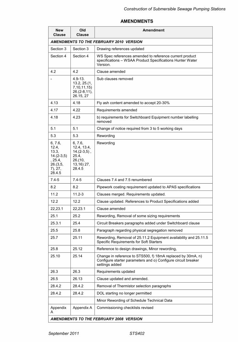
AMENDMENTS
NewClause
OldClause
Amendment
AMENDMENTS TO THE FEBRUARY 2010 VERSION
Section 3 Section 3 Drawing references updated
Section 4 Section 4 WS Spec references amended to reference current productspecifications – WSAA Product Specifications Hunter WaterVersion.
4.2 4.2 Clause amended
- 4.9-13.13.2, 25.(1,7,10,11,15)26.(2-8,11),26.15, 27
Sub clauses removed
4.13 4.18 Fly ash content amended to accept 20-30%
4.17 4.22 Requirements amended
4.18 4.23 b) requirements for Switchboard Equipment number labellingremoved
5.1 5.1 Change of notice required from 3 to 5 working days
5.3 5.3 Rewording
6, 7.6,12.4,13.3,14.(2-3,5), 25.4,26.(3,5,7), 27,28.4.5
6, 7.6,12.4, 13.4,14.(2-3,5) ,25.4,26.(10,13,16) 27,28.4.5
Rewording
7.4-5 7.4-5 Clauses 7.4 and 7.5 renumbered
8.2 8.2 Pipework coating requirement updated to APAS specifications
11.2 11.2-3 Clauses merged. Requirements updated.
12.2 12.2 Clause updated. References to Product Specifications added
22,23.1 22,23.1 Clause amended
25.1 25.2 Rewording, Removal of some sizing requirements
25.3.1 25.4 Circuit Breakers paragraphs added under Switchboard clause
25.5 25.8 Paragraph regarding physical segregation removed
25.7 25.11 Rewording, Removal of 25.11.2 Equipment availability and 25.11.5Specific Requirements for Soft Starters
25.8 25.12 Reference to design drawings, Minor rewording,
25.10 25.14 Change in reference to STS500, f) 18mA replaced by 30mA, n)Configure starter parameters and o) Configure circuit breakersettings added
26.3 26.3 Requirements updated
26.5 26.13 Clause updated and amended.
28.4.2 28.4.2 Removal of Thermistor selection paragraphs
28.4.2 28.4.2 DOL starting no longer permitted
Minor Rewording of Schedule Technical Data
AppendixA
Appendix A Commissioning checklists revised
AMENDMENTS TO THE FEBRUARY 2008 VERSION
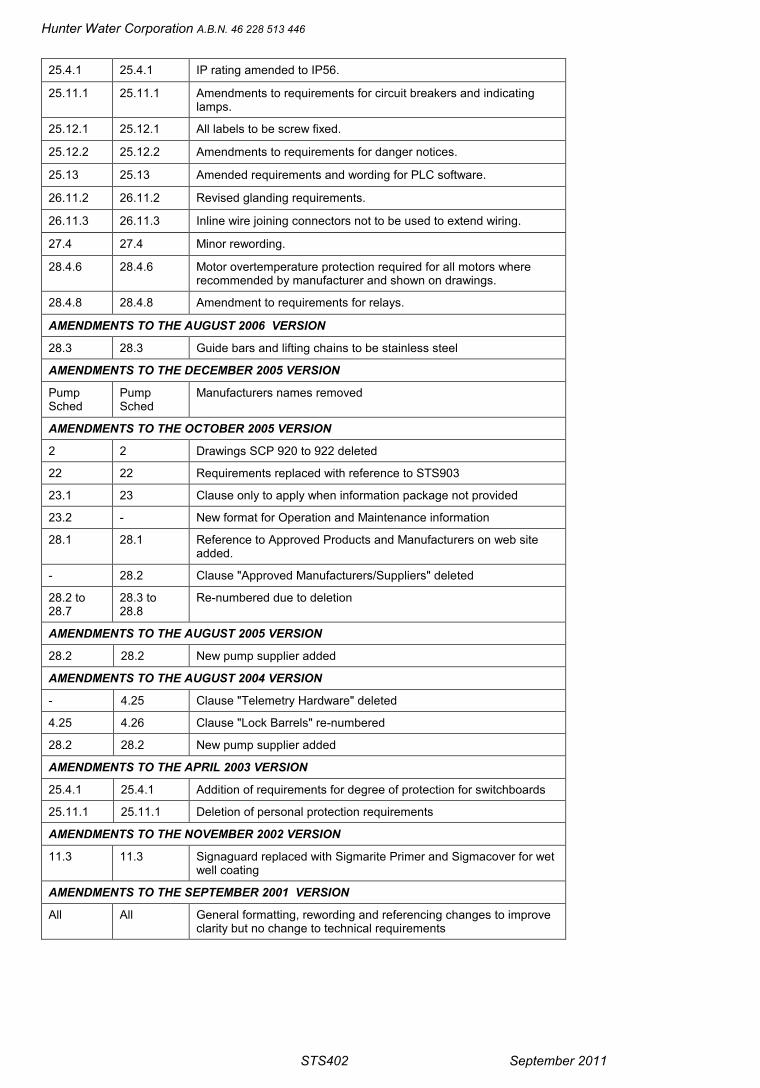
Hunter Water Corporation A.B.N. 46 228 513 446
STS402 September 2011
25.4.1 25.4.1 IP rating amended to IP56.
25.11.1 25.11.1 Amendments to requirements for circuit breakers and indicatinglamps.
25.12.1 25.12.1 All labels to be screw fixed.
25.12.2 25.12.2 Amendments to requirements for danger notices.
25.13 25.13 Amended requirements and wording for PLC software.
26.11.2 26.11.2 Revised glanding requirements.
26.11.3 26.11.3 Inline wire joining connectors not to be used to extend wiring.
27.4 27.4 Minor rewording.
28.4.6 28.4.6 Motor overtemperature protection required for all motors whererecommended by manufacturer and shown on drawings.
28.4.8 28.4.8 Amendment to requirements for relays.
AMENDMENTS TO THE AUGUST 2006 VERSION
28.3 28.3 Guide bars and lifting chains to be stainless steel
AMENDMENTS TO THE DECEMBER 2005 VERSION
PumpSched
PumpSched
Manufacturers names removed
AMENDMENTS TO THE OCTOBER 2005 VERSION
2 2 Drawings SCP 920 to 922 deleted
22 22 Requirements replaced with reference to STS903
23.1 23 Clause only to apply when information package not provided
23.2 - New format for Operation and Maintenance information
28.1 28.1 Reference to Approved Products and Manufacturers on web siteadded.
- 28.2 Clause "Approved Manufacturers/Suppliers" deleted
28.2 to28.7
28.3 to28.8
Re-numbered due to deletion
AMENDMENTS TO THE AUGUST 2005 VERSION
28.2 28.2 New pump supplier added
AMENDMENTS TO THE AUGUST 2004 VERSION
- 4.25 Clause "Telemetry Hardware" deleted
4.25 4.26 Clause "Lock Barrels" re-numbered
28.2 28.2 New pump supplier added
AMENDMENTS TO THE APRIL 2003 VERSION
25.4.1 25.4.1 Addition of requirements for degree of protection for switchboards
25.11.1 25.11.1 Deletion of personal protection requirements
AMENDMENTS TO THE NOVEMBER 2002 VERSION
11.3 11.3 Signaguard replaced with Sigmarite Primer and Sigmacover for wetwell coating
AMENDMENTS TO THE SEPTEMBER 2001 VERSION
All All General formatting, rewording and referencing changes to improveclarity but no change to technical requirements

Construction of Submersible Sewage Pumping Stations
September 2011 STS402 1
1. GENERAL
1.1 ScopeThis Standard Technical Specification details requirements for the construction of submersiblesewage pumping stations of nominal diameter DN 1800 to DN 4600 including associated workssuch as valve pits, vents and flow relief structures.
1.2 InterpretationUnless specifically stated otherwise, construction of submersible sewage pumping stationsincludes ALL functions described in this Standard Technical Specification and the provision ofany minor materials or services which are not described but are reasonably necessary toproduce a fully functional sewage pumping station.
Headings are for the convenience of the reader and shall not be used in the interpretation of thisStandard Technical Specification.
Unless the context requires otherwise any expression such as "give notice", "submit","approval", or "directed" means give notice to, submit to, approval by, or directed by the personnominated by the Principal or Purchaser.
2. REFERENCED DOCUMENTSThe following Hunter Water Corporation standard drawings are deemed to form part of thisStandard Technical Specification:
SCP-500 Flow Relief Structure Type 1 for DN 150 to 375 Sewers
SCP-501 Flow Relief Structure Type 1 Screen and Bracket Details
SCP-502 Flow Relief Structure Type 2 for DN 150 to 375 Sewers
SCP-503 Flow Relief Structure Type 3 for DN 150 to 375 Sewers
SCP-504 Flow Relief Structure Type 3 Steelwork Details
SCP-505 Flow Relief Structure Type 4 for DN 150 to 375 Sewers
SCP-506 Flow Relief Structure Type 4 Steelwork Details
SCP-600 Sewage Pumping Stations Circular Valve Pit Covers Marking Plan
SCP-601 Sewage Pumping Stations Circular Valve Pit Covers Cover Plate Details
SCP-602 Sewage Pumping Stations Circular Valve Pit Covers Beams and BracketDetails
SCP-603 Sewage Pumping Stations Rectangular Valve Pit Covers Marking Plan
SCP-604 Sewage Pumping Stations Rectangular Valve Pit Covers Cover PlateDetails
SCP-605 Sewage Pumping Stations Rectangular Valve Pit Covers Beams andBracket Details
SCP-700 Sewage Pumping Stations DN 1800 to 3000 Duplex SPS Concrete RoofSlab Plan
SCP-701 Sewage Pumping Stations DN 1800 to 3000 Duplex SPS Concrete RoofSlab Sections
SCP-704 Sewage Pumping Stations DN 3800 Duplex SPS (Small Cubicle)Concrete Roof Slab Plan

Hunter Water Corporation A.B.N. 46 228 513 446
2 STS402 September 2011
SCP-705 Sewage Pumping Stations DN 3800 Duplex SPS (Small Cubicle)Concrete Roof Slab Sections
SCP-708 Sewage Pumping Stations DN 3800 Duplex SPS (Large Cubicle)Concrete Roof Slab Plan
SCP-709 Sewage Pumping Stations DN 3800 Duplex SPS (Large Cubicle)Concrete Roof Slab Sections
SCP-710 Sewage Pumping Stations DN 4600 Duplex SPS Concrete Roof SlabPlan
SCP-711 Sewage Pumping Stations DN 4600 Duplex SPS Concrete Roof SlabSections
SCP-800 Sewage Pumping Stations Single Sliding Hatch Covers Marking Plan andDetails
SCP-801 Sewage Pumping Stations Single Sliding Hatch Covers Hatch CoverDetails
SCP-802 Sewage Pumping Stations Single Sliding Hatch Covers Door Stop andScreen Support Details
SCP-803 Sewage Pumping Stations Double Sliding Hatch Covers Marking Planand Details
SCP-804 Sewage Pumping Stations Double Sliding Hatch Covers Hatch CoverDetails
SCP-805 Sewage Pumping Stations Double Sliding Hatch Covers Door Stop andScreen Support Details
SCP-900 Sewage Pumping Stations DN 1800 to 3000 Precast Type Pump WellDetails
SCP-901 Sewage Pumping Stations Blockout and Puddle Flange Detail
SCP-902 Sewage Pumping Stations Drop Tubes and Pipe Clips
SCP-903 Sewage Pumping Stations Benching Details Without Baffle Wall
SCP-904 Sewage Pumping Stations Benching Details With Baffle Wall
SCP-905 Sewage Pumping Stations Induct Vent Pipe Clip
SCP-906 Sewage Pumping Stations Cable Holder and Chain Hook Details
SCP-907 Sewage Pumping Stations Cable Trench Covers
SCP-908 Sewage Pumping Stations Concrete Supports for Stop Valves and RefluxValves
SCP-909 Sewage Pumping Stations Valve Pits Monorail Ladder Details
SCP-910 Sewage Pumping Stations N55 Cast Iron Induct Vent
SCP-911 Sewage Pumping Stations Water Service Details
SCP-912 Sewage Pumping Stations Typical Pipework Arrangement and Details
SCP-923 Typical Electrical Installation Details
SCP-1000 Pipe Support and Trench Fill for Sewer Rising Mains up to DN 600
SCP-1001 Pipe Support and Trench Fill in Bad Ground for Sewer Rising Mains upto DN 600
SCP-1002 Discharge Access Chambers for Sewer Rising Mains up to DN 500
SCP-1003 Educt Vent Stack and Holding Down Bolt Details

Construction of Submersible Sewage Pumping Stations
September 2011 STS402 3
SCP-1004 Air Release Valve for DN 100 to 600 Sewer Rising Mains
SCP-1005 Pump Out Scour for DN 100 to 600 Sewer Rising Mains
SCP-1006 Gravity Scour for DN 100 to 600 Sewer Rising Mains
SCP-1007 Driveway / Roadway Crossings for Sewer Rising Mains up to DN 600
3. ORDER OF CONSTRUCTIONUndertake and complete all work including fittings before connection is made to the existingsewerage system.
4. MATERIALS
4.1 GeneralObtain all materials necessary for construction of the Works from approved sources. Complywith all recommendations of the manufacturers regarding the storage and handling of thematerials. Undertake all handling, transport and storage such that no damage occurs to thematerials including coatings and linings.
Select materials from Hunter Water's lists of Approved Products and Manufacturers which canbe accessed on the internet at:
http://www.hunterwater.com.au/Building-and-Development/
Where suitable materials are not listed, submit full technical details of proposed items andobtain written approval prior to use.
WSAA Product Specifications Hunter Water Version (WSA PS) can be accessed on theinternet at:
http://www.hunterwater.com.au/Building-and-Development/
4.2 On-site StockpilesOnly store sufficient materials on site as are necessary to allow timely and efficient progress ofthe work. Locate stockpiles of excavated or imported material where they cause no interferenceto the public, drainage routes or vehicular or pedestrian traffic. Clear lines of sight for driversmust not be obstructed. Do not stack materials against structures, fences, trees or other propertyimprovements. Leave a clear path at least 600 mm wide between the edge of any excavationand the inner toe of any stockpile or spoil banks.
Immediately remove all contaminated spoil to an approved waste facility. Any temporarystockpiles must be separated from backfill stockpiles and in accordance with NSW regulatoryrequirements.
4.3 Bedding SandSupply bedding sand embedment material in accordance with Standard Technical SpecificationSTS101.
4.4 High Grade Compaction SandSupply high grade compaction sand embedment material in accordance with StandardTechnical Specification STS101.
4.5 Select FillFor select fill use excavated material, free from organic matter and having a particle size nolarger than 20 mm. The material shall be suitable to allow compaction as specified withoutcausing damage to the pipeline. If material excavated during excavation does not comply,import non-cohesive material.

Hunter Water Corporation A.B.N. 46 228 513 446
4 STS402 September 2011
4.6 Trench FillWhere the trench is not subject to traffic loading use excavated material for fill in the trench fillzone provided it has a particle size no greater than 75 mm across the largest dimension, is freefrom organic matter and can be placed into a dense mass free of voids and cavities.
For trafficable areas use:
- cement stabilised trench fill for all existing roads; or
- crushed rock dust in accordance with Standard Technical Specification STS101; or
- crushed rock in accordance with Standard Technical Specification STS102; or
- as directed by the authority responsible for the trafficable area.
4.7 Cement Stabilised Trench FillCement stabilised trench fill shall comprise a 14:1 sand : cement mix.
4.8 Pipes and FittingsSupply pipes and fittings in compliance WSAA Product Specifications Hunter Water Version.
Do not use UPVC pressure pipes exceeding 6 months of age from the date of manufacture. Allfittings for UPVC pressure pipelines DN 100 and greater are to be ductile iron to clause 4.9 andinternally and externally coated with a thermal bonded coating in accordance with SectionSP30 of WS-Spec.
4.9 Polyethylene SleevingFor all ductile iron mains use polyethylene sleeving, adhesive tape, strap and buckle inaccordance with WSA PS 320.
4.10 Geotextile Filter FabricGeotextile filter fabric shall be approved inert material, BIDIM A14, manufactured byGeofabric Australia Pty Limited or approved equivalent.
4.11 Timber PilesAll piles are to be treated hardwood, strength group F14, and in accordance with "Koppers -Standard Specification, Hardwood Foundation Piling". The CCA treatment shall be to therequirements of AS 1604 Hazard Level 5 protection and the further requirements of the NSWTimber Market Act.
4.12 FastenersSupply all nuts, bolts and washers in accordance with AS 2528. All exposed boltheads and nutsshall be hexagonal and the length of all bolts shall be such that tightened bolted connectionsshall have a minimum of 2.5 threads and a maximum of 5 threads protruding from the nut.
All anchors, bolts, nuts and washers either embedded in concrete, installed within the wet welland/or used in the fabrication and/or installation of stainless steel items shall be of Grade 316stainless steel to AS 2837. All other steel anchors, bolts, washers and nuts shall be hot dipgalvanised in accordance with AS 1650. Grade 316 stainless steel to AS 2837 is an acceptablealternative to hot dip galvanised steel. Passivate all stainless steel components in accordancewith STS100.
4.13 CementUse only one of the following cements:
- Fly Ash Blended Cement conforming to the requirements of Type SR to AS 3972 andcontaining 20-30% fly ash to AS 3582 Part 1, “fine grade” only, or

Construction of Submersible Sewage Pumping Stations
September 2011 STS402 5
- Blended Cement, other than fly ash, conforming to the requirements of Type SR toAS 3972.
4.14 ConcreteSupply normal class concrete in accordance with WSA PS 358.
Supply special class concrete in accordance with WSA PS 358.
Supply concrete from plant(s) with third party certified Quality Systems for the manufactureand supply of concrete. Do not use any admixtures in the concrete.
4.15 ReinforcementSupply reinforcement which complies with AS 1302 Steel reinforcing bars for concrete,AS 1303 Steel reinforcing wire for concrete, and/or AS 1304 Welded wire reinforcing fabricfor concrete.
4.16 AppurtenancesSupply all appurtenances in accordance with WSAA Product Specifications Hunter WaterVersion.
4.17 Knife Gate ValvesSupply knife gate valves manufactured to WSA PS 266 and the following additionalrequirements:-
(a) Enclosed bonnet not required
(b) The knife gate valves are to be suitable for installation in applications where theyshall be subject to submergence in or splashing by sewage or sludge.
(c) The valve body shall be of wafer design for bolting between flanges with 316stainless steel bolts, nuts and washers.
(d) The stem of the valve is to be driven through a fixed bronze drive bush driven by astainless steel drive tube fitted with a Hunter Water Corporation standard squaredrive. The valve stem will rise within the drive tube such that when in the fully openposition the valve stem is to be isolated from sewage contamination by being enclosedin the drive tube. The valve stem is to be attached centrally to the gate and not offset.(DeZurik non rising adaptor or similar.)
(e) Extension stems are to be hot dip galvanised mild steel with female square drive fittedto valve drive and with Hunter Water Corporation standard square top drive.Extension stems over 3 metres shall be supported with spindle support brackets.
4.18 Equipment Number LabelsManufacture Equipment Number Labels from:
(a) Pumping Station Equipment Number Label - Zinc anneal steel sheet 80 mm high with50 mm high black uppercase embossed lettering on a white reflective background.
(b) Pump Equipment Number Labels
(i) on hatch cover - 1.2 mm thick silver anodised aluminium sheet by 30 mm highengraved with 15 mm high uppercase lettering.
(ii) adjacent to circuit breaker - Laminated plastic engraved with 5 mm high blackuppercase lettering on a white background.
The equipment number is listed in Appendix C.

Hunter Water Corporation A.B.N. 46 228 513 446
6 STS402 September 2011
4.19 Metering EquipmentObtain Metering Equipment for the electrical switchboard from the Supply Authority.
4.20 Lock BarrelsObtain lock barrels for the pumping station switchboard from the Hunter Water Corporation.Contact the Superintendent regarding supply of lock barrels.
5. EXISTING SERVICES
5.1 Location of ServicesAny details of services shown on the Drawings are not to be taken as indicating all existingservices or exact locations. Irrespective of any information on the Drawings, verify the exactlocation of all services which may be affected by construction activities. If services are locatedwhich are not shown on the Drawings or are not in the location shown on the Drawings, givenotice at least five (5) working days prior to commencement of any construction activity thatmay affect the service.
5.2 Protection and Maintenance of ServicesTake all actions and provide all things necessary to protect and maintain existing services to thesatisfaction of the relevant authority or owner. This may include arranging or performingrelocation, temporary diversion or support of the service.
5.3 Repair of ServicesIf a service is damaged during construction, arrange or perform repair to the satisfaction of thecontrolling authority or owner. Obtain from the authority or owner, a certificate stating that therepair has been carried out to their satisfaction.
If the service is not under the control of an authority and the owner cannot be located within areasonable time, report the damage, and arrange or perform repair to an approved standard. Donot backfill, cover up or make the repair inaccessible prior to obtaining approval from HunterWater.
6. CLEARINGDo not destroy, remove or clear vegetation or surface improvements to an extent greater thannecessary for the execution of works.
Obtain the approval of the Council for the removal of any trees. Take all steps necessary toprevent damage to trees that are not to be removed.
Dispose of all rubbish and surplus material within 24 hours of clearing to an approved wastefacility.
Stockpile topsoil separate from other excavated material and use it to make good the surfaceafter backfilling.
7. EXCAVATION
7.1 Limits of ExcavationKeep the extent of excavation to the minimum possible to allow efficient construction of theWorks while meeting the minimum requirements shown on the Drawings and the relevantStandard Drawings. Keep pipe trench widths within the maximum widths recommended by thepipe manufacturer.
Keep the sides of excavations for pipework vertical to at least 150 mm above the pipe.

Construction of Submersible Sewage Pumping Stations
September 2011 STS402 7
Ensure that the minimum cover requirements will be satisfied following any earthworks whichmay occur in the area of the pipelines and services to the pumping station. This is particularlyrelevant in new subdivisions or developments where earthworks are to be expected to formroads, driveways, footpaths and for general shaping of the surfaces. Preferably lay services afterformation of surfaces to finished levels. If minimum cover requirements cannot be achievedsubmit a proposal to overcome the problem.
7.2 Improved SurfacesWhere excavation is required under improved surfaces such as pavements, driveways and kerband gutter, use tunnelling or boring where the surfaces cannot be satisfactorily reproduced andunder existing concrete footway areas and concrete driveways. Ensure backfilling is to astandard to fully support the surface and any likely applied load.
If open excavations are used in improved surfaces, keep the excavation width to the minimumallowed. Saw cut neat straight lines at the outer limits of the excavation through bitumen,asphalt and concrete. Remove pavers, blocks or brick pavements by hand, clean them and setthem aside for later replacement.
7.3 Drainage and DewateringKeep all excavations free of water. Provide, maintain and operate intercepting works to preventsurface water from entering the excavations; and all equipment necessary for dewatering theexcavations and keeping the Works free from water.
Dewatering permits must be obtained from the relevant authority prior to undertaking anydewatering activities.
Lowering of the water table by well points or other external dewatering methods may only beused if no damage is likely to be caused to adjacent structures and services.
Ensure that all downstream works that are under construction, completed or in use are protectedat all times against the effects of any drainage which is discharged or likely to be dischargedfrom the work.
7.4 Foundations and Foundation StabilisationWhere the bottom of an excavation is soft or considered to provide an unacceptable foundationproduce a stable foundation by one of the following:
(a) Use of geotextile surround as shown on Standard Drawing SCP-1001 for pipework.For other structures place geotextile fabric across the full excavation width andextending up the sides to minimum level of 600 above the base of the excavation.
(b) Extra depth excavation in accordance with clause 1.1.
(c) Ram ballast into the soft ground until an approved firm foundation is obtained at thedesign depth. Use ballast comprising clean hard rock of 100 mm nominal size havingno less than 85% retained by a 100 mm sieve and no less than 95% retained by a80 mm sieve, Remove and dispose of any excess material.
Give notice prior to commencing any foundation stabilisation.
7.5 Extra Depth ExcavationIf extra excavation is required to reach a firm foundation or if excavation has extended deeperthan necessary to meet the requirements of this Standard Technical Specification, refill to therequired level with an approved non-cohesive material complying with STS101. Place andcompact the material in accordance with clause 9.1.
Where material has been disturbed to a level deeper than necessary under this StandardTechnical Specification, compact the disturbed material to density index not less than 70% forgranular (non-cohesive) material or to dry density ratio not less than 95% for non-granular(cohesive) material. If satisfactory compaction of the disturbed material cannot be achieved,
Hunter Water Corporation A.B.N. 46 228 513 446
8 STS402 September 2011
remove the material and refill to the required level with an approved non-cohesive materialcomplying with STS101. Place and compact the material in accordance with clause 9.1.
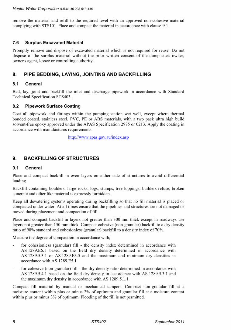
7.6 Surplus Excavated MaterialPromptly remove and dispose of excavated material which is not required for reuse. Do notdispose of the surplus material without the prior written consent of the dump site's owner,owner's agent, lessee or controlling authority.
8. PIPE BEDDING, LAYING, JOINTING AND BACKFILLING
8.1 GeneralBed, lay, joint and backfill the inlet and discharge pipework in accordance with StandardTechnical Specification STS403.
8.2 Pipework Surface CoatingCoat all pipework and fittings within the pumping station wet well, except where thermalbonded coated, stainless steel, PVC, PE or ABS materials, with a two pack ultra high buildsolvent-free epoxy approved under the APAS Specification 2975 or 0213. Apply the coating inaccordance with manufactures requirements.
http://www.apas.gov.au/index.asp
9. BACKFILLING OF STRUCTURES
9.1 GeneralPlace and compact backfill in even layers on either side of structures to avoid differentialloading.
Backfill containing boulders, large rocks, logs, stumps, tree loppings, builders refuse, brokenconcrete and other like material is expressly forbidden.
Keep all dewatering systems operating during backfilling so that no fill material is placed orcompacted under water. At all times ensure that the pipelines and structures are not damaged ormoved during placement and compaction of fill.
Place and compact backfill in layers not greater than 300 mm thick except in roadways uselayers not greater than 150 mm thick. Compact cohesive (non-granular) backfill to a dry densityratio of 98% standard and cohesionless (granular) backfill to a density index of 70%.
Measure the degree of compaction in accordance with;
- for cohesionless (granular) fill - the density index determined in accordance withAS 1289.E6.1 based on the field dry density determined in accordance withAS 1289.5.3.1 or AS 1289.E3.5 and the maximum and minimum dry densities inaccordance with AS 1289.E5.1
- for cohesive (non-granular) fill - the dry density ratio determined in accordance withAS 1289.5.4.1 based on the field dry density in accordance with AS 1289.5.3.1 andthe maximum dry density in accordance with AS 1289.5.1.1.
Compact fill material by manual or mechanical tampers. Compact non-granular fill at amoisture content within plus or minus 2% of optimum and granular fill at a moisture contentwithin plus or minus 3% of optimum. Flooding of the fill is not permitted.
Construction of Submersible Sewage Pumping Stations
September 2011 STS402 9
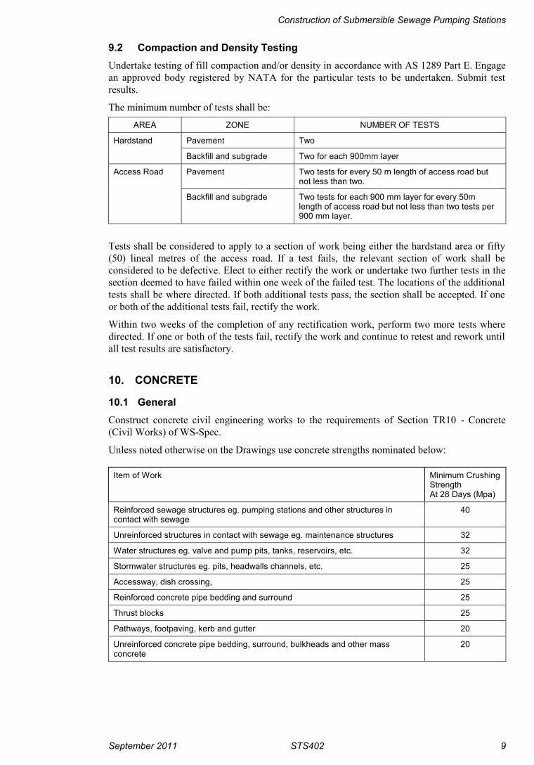
9.2 Compaction and Density TestingUndertake testing of fill compaction and/or density in accordance with AS 1289 Part E. Engagean approved body registered by NATA for the particular tests to be undertaken. Submit testresults.
The minimum number of tests shall be:
AREA ZONE NUMBER OF TESTS
Hardstand Pavement Two
Backfill and subgrade Two for each 900mm layer
Access Road Pavement Two tests for every 50 m length of access road butnot less than two.
Backfill and subgrade Two tests for each 900 mm layer for every 50mlength of access road but not less than two tests per900 mm layer.
Tests shall be considered to apply to a section of work being either the hardstand area or fifty(50) lineal metres of the access road. If a test fails, the relevant section of work shall beconsidered to be defective. Elect to either rectify the work or undertake two further tests in thesection deemed to have failed within one week of the failed test. The locations of the additionaltests shall be where directed. If both additional tests pass, the section shall be accepted. If oneor both of the additional tests fail, rectify the work.
Within two weeks of the completion of any rectification work, perform two more tests wheredirected. If one or both of the tests fail, rectify the work and continue to retest and rework untilall test results are satisfactory.
10. CONCRETE
10.1 GeneralConstruct concrete civil engineering works to the requirements of Section TR10 - Concrete(Civil Works) of WS-Spec.
Unless noted otherwise on the Drawings use concrete strengths nominated below:
Item of Work Minimum CrushingStrengthAt 28 Days (Mpa)
Reinforced sewage structures eg. pumping stations and other structures incontact with sewage
40
Unreinforced structures in contact with sewage eg. maintenance structures 32
Water structures eg. valve and pump pits, tanks, reservoirs, etc. 32
Stormwater structures eg. pits, headwalls channels, etc. 25
Accessway, dish crossing, 25
Reinforced concrete pipe bedding and surround 25
Thrust blocks 25
Pathways, footpaving, kerb and gutter 20
Unreinforced concrete pipe bedding, surround, bulkheads and other massconcrete
20

Hunter Water Corporation A.B.N. 46 228 513 446
10 STS402 September 2011
10.2 Identification CertificateThe Identification Certificate accompanying each load delivered to site shall include thefollowing further details:-
(a) time at which the concrete was batched
(b) size of the load in cubic metres.
(c) type of concrete eg. Grade 20.
(d) total cement content of the load in kilograms (kg).
(e) amount of free water batched in litres (L).
(f) slump at time of batching in millimetres (mm).
(g) type of cement used.
Do not use concrete supplied without a completed Identification Certificate.
10.3 Expansion and Contraction Joints
10.3.1 Kerbing
Weakened plane (contraction) joints shall be 3 mm wide, clean cut and made vertically throughthe concrete at right-angles to the direction of the work. Normally they shall be spaced at 3 mintervals with minor adjustments to avoid short closing lengths.
Form expansion joints adjacent to other structures. Expansion joints shall be sealed with 15 mmwide preformed, self-expanding cork joint sealer cut to the full profile of the kerb section.Remove tape from top of sealer at about the time of final set of the concrete.
Joint arrises abutting cork joint sealer shall not be tooled off.
10.3.2 Footpaths and Minor Paving
Joints shall be straight, continuous and normal to the surface of the pavement.
Weakened plane joints shall be formed by making a cut 3 mm wide for at least one quarter ofthe depth of the paving. Arrises shall be tooled to a suitable radius. Space weakened planejoints at 2 metre intervals with minor adjustments to avoid short closing lengths.
Expansion joints shall be constructed for the full depth of the paving using 15 mm widepreformed self-expanding cork joint sealer. They shall be provided where ever the paving abutsfixed structures, such as buildings and pits, transversely at maximum intervals of 15 m alongpath and at path intersections. Joint sealer shall be bonded to the first placed concrete using asuitable contact adhesive. Remove tape from top of sealer at about the time of final set of theconcrete. Joint arrises abutting cork joint sealer shall not be tooled off.
10.3.3 Accessways and other structures
All joints to the details shown on the Drawings.
10.4 Blockouts and Cored Holes(a) Unless blockouts or cored holes are shown on the Drawings all pipes and fittings shall
be cast into the structure when the structure itself is poured. Where this is not possiblesubmit details of blockouts or alternative methods for approval. Details shouldconform to details shown on Drawing SCP-901;
(b) All pipes which are cast into the concrete shall be thoroughly cleaned to remove alltraces of dust, grease, rust and paint prior to the placement of concrete to secure atight bond with the concrete;
(c) Where cored holes or blockouts are to be grouted to hold pipework, bolts and otherfittings, the cored holes or blockout shall be scabbled and treated with an epoxy

Construction of Submersible Sewage Pumping Stations
September 2011 STS402 11
compound, such as Hilti CA80 ,Epirez 133 or Epirez 633, strictly in accordance withthe Manufacturer's instructions;
(d) Openings shall be constructed so as to leave a minimum clearance of 100 mmbetween finished concrete and the location of the item to be cast-in. Reinforcementshall be constructed continuously through openings as detailed on the reinforcementDrawings and shall be trimmed around the item to be cast-in at a maximum distanceof 50 mm from the item;
(e) After placing the pipe and fitting, the remaining void shall be carefully filled withepoxy mortar, such as Hilti CA80 or Epirez 633 mixed , using appropriate sand (either Epirez No 2 Quartzite Aggregate or Hilti CTS 99 Graded Sand ), to theManufacturer’s written instructions, to produce a watertight joint. The epoxy mortarshall be retained by a form which shall be built up as filling proceeds;
(f) Where fixing bolts to be cast-in are positioned by means of a template they shall besupplied with a backing nut and a face nut for secure fixing of the bolt. The backingnut shall be cast into the concrete;
(g) Aluminium or ferrous structural members built into brick or concrete shall have theircontact surfaces first painted with two (2) coats of bituminous paint.
10.5 Cast In ItemsAll anchor bolts and fastenings cast in concrete shall be Stainless Steel Grade 316 to AS 2837unless otherwise shown on the Drawings.
10.6 Specific RequirementsUnless specified otherwise, the following requirements shall apply. See Clause 9.2 of SectionTR10 of WS-Spec.
CLASS AND GRADECLAUSE(TR10)
S40 S32 S25 N20
OTHER Curing Compound AcceptedYes/No
6.9 No No No No
Minimum Period Between AdjacentPours (Days)
6.1 2 2 2 2
SURFACEFINISH -FORMED
Surfaces exposed to sewage,effluent, or sewage gases.
6.7 F3 F3 F3
Surfaces of water retainingstructures exposed to water.
F3 F3 F3
Internal surfaces and all exposedsurfaces, except trafficablesurfaces.
F2 F2 F2 F2
Internal trafficable surfaces. F2 F2 F2 F2
External trafficable surfaces. F2 F2 F2 F2
Concealed surfaces. F1 F1 F1 F1
SURFACEFINISH -UNFORMED
Surfaces exposed to sewage,effluent, or sewage gases.
6.8 U3 U3 U3
Surfaces of water retainingstructures exposed to water.
U3 U3 U3
Internal surfaces and all exposedsurfaces, except trafficablesurfaces.
U2 U2 U2 U2
Internal trafficable surfaces. U5* U5* U5* U5*

Hunter Water Corporation A.B.N. 46 228 513 446
12 STS402 September 2011
External trafficable surfaces. U4* U4* U4* U4*
Concealed surfaces U1 U1 U1 U1
Refer to clause 10.7 for requirements for Class U4 and Class U5.
10.7 Unformed Surfaces FinishRequirement: Additional to finishes specified in Clause 6.8 of Section TR10 of WS-Spec,provide one of the following classes as specified:
Class U4 - (Broom finish)
Wood float finish Class U2 to be lightly broomed at right angles to the alignment of thepavement.
Acceptance criteria
- Abrupt irregularities less than 5 mm
- Gradual irregularities less than 5 mm
Class U5 - ( Sponge Float - Trafficable)
Steel trowelled finish Class U3 to be sponge floated.
Acceptance criteria
- Abrupt irregularities less than 2 mm
- Gradual irregularities less than 5 mm
10.8 Topping and BenchingBenching shall have a minimum thickness of 25 mm. Cement content of the topping mix shallbe the same as that of the structural concrete being topped or benched. Prior to placing thebenching concrete and the grout beneath the pump pedestal, scabble the concrete surface andapply Hilti CA80 or Epirez 133 epoxy.
Place benching concrete to the dimensions as shown on the Drawings in the wet well followingthe installation of the pump pedestals and the discharge pipework. Ensure the topping orbenching is dense, uniform and the surface free from blemishes. Remove any splatter or solidslodged in or upon the pedestal or pipework.
10.9 Concrete RepairsRepair air voids, bolt holes and honeycombing using an epoxy paste such as Hilti CA273.Repairs by bagging and cement mortar are not permitted.
For thin bed bonding use Hilti CA80 or Epirez 133.
10.10 TestingThe Contractor shall arrange for concrete sampling and testing, including transportation ofcylinders. A minimum of 2 cylinders shall be taken for all concrete supplies over one cubicmetre. A Slump Test shall also be carried out at the time that the cylinders are taken. Samplingand Testing shall be in accordance with relevant Australian Standards, using NATA certifiedtests. The cost for all these works shall be borne by the Contractor.
Minimum crushing strength and slump when tested in accordance with SP45 of WS-Spec,cement content and water / cement ratio shall be in accordance with clause 10.1 and 4.14.
Construction of Submersible Sewage Pumping Stations
September 2011 STS402 13
11. PUMPING STATION WET WELL
11.1 FlotationEnsure that any partly or fully completed structures do not move due to hydrostatic pressures.
11.2 Corrosion Protection
11.2.1 Roof Structures
Protect the underside of the concrete roof slabs by impregnating a PVC or PE sheet, Plastilineor HWC approved equivalent, into the roof. Ensure the complete adhesion of the sheet to theunderside of the roof, particularly around roof openings. All sheet joints are to be joined inaccordance with manufacturer requirements. Submit details of sheet joining technique to theSuperintendent for approval prior to undertaking the works. Ensure complete coverage to theextents shown on the Design Drawings.
11.2.2 Cast In-Situ Concrete
Apply a 100% solids, solventless, elastomeric polyurethane coating, Polybrid 705e or HWCapproved equivalent, to the internal concrete surfaces as indicated on the Drawings. Prepare theconcrete surface and apply the coating in strict accordance with the coating manufacturer’swritten instructions. Contractor, application method, repair procedures and all works associatedwith the application of the coating to be approved by the manufacturer.
11.3 Precast Concrete UnitsManufacture pipe units to include blockouts or cored holes shown on the Drawings.
Supply all precast units with an approved method for lifting.
Handle, store and transport to avoid damage.
11.4 TolerancesThe following tolerances shall apply to the wet well:-
(a) In the final position, the centreline of the wet well shall not vary from plumb by morethan 1 (horizontal) to 100 (vertical).
(b) In the final position, the trace of the centreline of the wet well at the surface must becontained within a circle centred in the design position and of radius 150 mm.
11.5 BlockoutsOn completion of pipework installation, epoxy mortar fill all blockouts in concrete structures inaccordance with clause 10.4. Finish surfaces flush with the internal surface of all structures.
11.6 Cast Insitu PlugScabble the internal surface of the wall of the wet well in the area of the plug before casting theplug.
12. WATER SUPPLY TO PUMPING STATION
12.1 GeneralProvide the water service to the pumping station site from Hunter Water Corporation mains asindicated on the Drawings and in accordance with standard drawing SCP-911.
Comply with the requirements of the AS 3500.1 and the further requirements of Hunter WaterCorporation and this Specification. All work shall be carried out by a plumber licensed by theDepartment of Fair Training and a permit submitted to the Hunter Water Corporation 48 hoursprior to the commencement of any work.

Hunter Water Corporation A.B.N. 46 228 513 446
14 STS402 September 2011
Supply and install including excavation, backfill, compaction and restoration, the following:
- a main tap into the Corporation's watermain;
- water service from the main tap to the water meter;
- water meter and approved testable reduced pressure zone device (RPZD) complyingwith AS 2845.1 and with replaceable seats and check modules;
- a pressure pipe from the water meter to the hose tap at the pumping station;
- a 25 mm nominal size copper standpipe fitted with a 20 mm nominal size vandal proofDR brass hose tap.
The pipe diameters shall be as nominated on the Drawings.
12.2 MaterialsFrom the main tap to the meter stand and from the meter stand to the standpipe at the pumpingstation the water service shall be either :
(a) Copper pipe to WSA PS 214.
(b) Polyethylene pipe to WSA PS 215
Vertical risers, the meter stand and the standpipe shall be Copper pipe Type A to AS 1432.
12.3 InstallationThe water service shall be laid in accordance WSA03 Water Supply Code HWC DrawingsWAT-1106V, WAT-1108V and WAT-1109V. Lay service at the Hunter Water Preferredminimum cover as indicated on drawing WAT-1201V.
12.4 Support PostsThe hose tap standpipe and each vertical leg of the meter stand shall be secured to a 100 x 100x 1500 mm hardwood backing post by copper saddles fixed with brass screws. Below ground,the posts shall have two coats of bituminous paint. Above ground, the posts shall be primed andthan painted with two (2) coats of white exterior enamel. The posts shall be driven 600 mm intothe ground. In rock the posts shall be set in Grade 20 concrete to a minimum depth of 300 mm.
12.5 Path BoxInstall a cast iron path box over the main tap in the watermain in accordance with DrawingSCP-911, where either of the following occur :-
(a) The meter stand is located more than 30 metres from the maintap.
(b) The service pipe from the main tap to the meter stand is not laid at right angles to thewatermain.
13. INSTALLATION OF ELECTRICAL CONDUITS
13.1 GeneralInstall electrical conduits in accordance with STS500.
Install a continuous 2 mm diameter galvanised mild steel draw wire inside each conduit run.The draw wire shall be of sufficient length to allow one (1) metre to be folded back into eachend of the conduit run.
13.2 Vent Stack Draw WireThe draw wire in the conduit to the base of the vent stack shall be left long enough to protrudeat least one (1) metre above the vent stack. After the vent stack is installed this draw wire is tobe left coiled around the top of the outside of the vent stack.

Construction of Submersible Sewage Pumping Stations
September 2011 STS402 15
13.3 Switchboard - Location Remote from Pumping Station Wet WellWhere the switchboard cabinet is located remote from the pumping station roof slab provide aseries of UPVC conduits, as shown on the respective Drawings..
Provide a 2 mm diameter stainless steel draw wire in each UPVC conduit between the concreteupstand and the wet well. Fit a suitable shackle or pulling eye to each end of each stainless steeldraw wire to facilitate the pulling of cables in/out of the conduit. Permanently fix each drawwire to the base of the concrete upstand adjacent to each conduit.
14. MECHANICAL INSTALLATION OF PUMPS, VALVES AND FITTINGS
14.1 GeneralLengths are to be determined accurately and items installed in such a manner as to ensure noundue loading on pumping units or pipework.
Prevent damage to or deterioration of pumps, electrical cables and ancillary equipment prior toputting into service and comply with manufacturer’s recommendations for storage. Powercables shall be coiled and supported with cable sleeves on the hooks provided and with freeends protected and above any possible accumulation of water.
14.2 Flanged JointsSelect bolting in accordance with AS 4087 Appendix B.
Assemble flanged joints in accordance with AS 4087 Appendix C and the followingrequirements.
Use washers under all nuts. In addition, use washers under bolt heads for connection to itemswith protective coatings.
Where stainless steel fasteners are used to fasten galvanised items, install high strength fibre orphenolic insulating washers and sleeves between the stainless steel washers / bolts and thegalvanised item being fixed or jointed.
All bolts, nuts, washers and locking devices in the flanges of the pumps and pipework andaccessories in the pump wells shall be stainless steel to AS 2837 Grade 316. Apply "Loctite"nickel anti seize thread lubricant to all stainless steel fasteners prior to fitting nuts.
Where use of dismantling joints is indicated on Drawings they shall be of the type specified onthe design drawings. Connect puddle and thrust flanges with a metal to metal epoxy. Prior toconnection of puddle or thrust flanges, remove surface coatings on flanges and the pipe at thelocation of connection.
14.3 Installation of Pump UnitsInstall pumping units and associated items including guide rails, upper guide brackets,discharge bend pedestals, lifting chains and holding down bolts in accordance with writteninstructions and approved Drawings supplied by the pump manufacturer. Set the pumping unitdischarge connections true and square by means of steel levelling wedges and with clearance topumping station floor as set out on the Drawings. Check alignment with discharge pipework(including eccentric tapers where fitted) and with guide rails before final positioning.
Ensure correct seating into the discharge connections and free movement of the pumps alongthe guide rails. The pumping units and associated equipment shall be installed free of anyundue stresses, strains or vibrations and be accessible for maintenance.
Set all foundation bolts to their maximum depth using an epoxy grout Epirez 133 withEpirez No 2 Quartzite Aggregate to a maximum ratio of 1:2 by volume or Hilti CA80 withHilti CTS 99 Graded Sand to a maximum ratio of 1:2 by volume.

Hunter Water Corporation A.B.N. 46 228 513 446
16 STS402 September 2011
Fix the upper guide rails brackets to the vertical face of the access opening using grade 316stainless steel chemical anchors to manufacturer’s specifications. All anchors to have aminimum anchor depth of 70 mm.
14.4 Pump NumbersSupply 100 mm high pump numbers cut from 2.5 mm thick marine grade C5251-H34aluminium or grade 316 stainless steel. The numbers shall be the pump and starter number ie.“1”, “2“, “3”.
Install the pump numbers adjacent to the top of each pump guide rail and so as to be easily seenfrom the pumping station roof using grade 316 stainless steel expanding metal sleeve masonryanchors.
The pump with the lowest serial number shall be the No 1 pump and shall be installed closest tothe electrical switchboard.
14.5 Test Tapping PointsProvide three DN 10 mm (3/8”) BSP tappings and supply and install, at each tapping, a 1/2"BSP Ball Valve (or metric equivalent) and fittings as required to complete installation. Valvesand fittings to be bronze or stainless steel. Fit removable caps to all valves.
14.6 Pump Equipment Number Labels - Hatch CoverFix each label, using four (4) aluminium pop rivets, to the top of the sliding hatch cover suchthat the label shall be adjacent to the respective pump guide rail when the hatch cover is open.The equipment number is listed in Appendix C. Do not paint.
15. METALWORK
15.1 SteelworkUse Grade 250 steel in accordance with AS/NZS 3678, and AS/NZS 3679. Fabricate inaccordance with AS 4100. Round all cut edges to 2 mm radius.
Except where otherwise noted on the Drawings, hot dip galvanise all steelwork including ventstack after fabrication, all in accordance with AS 1650. Do not weld galvanised componentsafter galvanising.
Prior to galvanising, clean the steelwork surface of all dirt, weld spatter, grease, slag, oil, paintor other deleterious matter and chemically descale in accordance with AS 1627 Part 5, orabrasive blast clean in accordance with AS 1627 Part 4 to Class 3 standard.
The zinc coating shall consist of a uniform layer of commercially pure zinc free from abrasion,cracks, blisters, chemical spots or other imperfections and shall adhere firmly to the surface ofthe steel. The thickness of zinc coating shall not be less than 100 microns at any point.
Any surface damage to the galvanising shall be shot or grit blasted clean and given two coats ofAmercoat No 62 primer. Apply the second coat after the first coat is touch dry and withintwenty-four hours of application of the first coat.
Where site welding of galvanised steelwork has been approved, the resulting weldment is to bechipped and cleaned to bare metal and painted with Galment zinc enriched paint.
15.2 Aluminium ComponentsAluminium components shall be grade 6061, 6063, 6351, 5083 or 5251. Fabricate inaccordance with AS 1664 and AS 1665. Apply two coats of bituminous paint to surfaces ofaluminium components in contact with concrete.
Construction of Submersible Sewage Pumping Stations
September 2011 STS402 17
15.3 Stainless Steel ComponentsStainless steel shall conform to AS 2837 type 302, 304, 304L, 316, 321 or SAF2304. The freemachining type 303 is not acceptable.
Passivate all stainless steel components in accordance with Standard Technical SpecificationSTS100.
15.4 FastenersAll nuts, bolts and washers shall be in accordance with AS/NZS 1111 and AS/NZS 1112 orAS/NZS 1252. All exposed boltheads and nuts shall be hexagonal and the length of all boltsshall be such that bolted connections shall have a minimum of 2.5 threads and a maximum of 5threads protruding from the nut.
Use washers under all nuts. In addition, use washers under bolt heads for connection to itemswith protective coatings.
Where stainless steel fasteners are used to fasten galvanised items, install high strength fibre orphenolic insulating washers and sleeves between the stainless steel washers / bolts and thegalvanised item being fixed or jointed.
All anchors, bolts, nuts and washers either embedded in concrete or within the pumping stationwet well (including above the nominated top water level) shall be of Grade 316 stainless steelto AS 2837.
All bolts, nuts and washers used in the fabrication and/or installation of stainless steel itemsshall be of stainless steel and of similar grades to the items being fixed or jointed. All othersteel anchors, bolts, washers and nuts shall be hot dip galvanised in accordance with AS 1650.In addition, coat all nuts and bolts which are to be installed in ground, except Grade 316stainless steel, with Denso 300 Primer and 400 Mastic/440 Cord, then wrap the entire joint inDenso 600 Tape (double thickness) and over wrap with Denso 931 Overwrap (minimum 55%overlap), all in accordance with the Manufacturer's recommendations. Grade 316 stainless steelto AS 2837 is an acceptable alternative to hot dip galvanised steel.
Apply loctite nickel anti-seize thread lubricant to the threads of all stainless steel nuts and boltsprior to assembly.
15.5 Educt Vent StackSubsequent to galvanising, powder coat the educt vent stack to the following specification:-
(a) (a) Apply a conversion coating of iron phosphate, through a three stage pretreatment,as follows:-
(i) Combined iron phosphate/cleaner.
(ii) Fresh water rinse.
(iii) Acidulated rinse.
(b) Ensure the removal of all moisture prior to powder coating, by passing theconveyorised metal through a drying oven.
(c) Apply, in accordance with the manufacturers recommendations, a cured oxysalt PR23Polyester powder of Hawthorne Green colour by electrostatic spray to a minimumthickness of 50 microns, and cured at temperatures recommended by the powdermanufacturer.
Supply and install a bird proof cowling manufactured of powder coated (Hawthorn Green)galvanised steel mesh to each vent stack.

Hunter Water Corporation A.B.N. 46 228 513 446
18 STS402 September 2011
16. ACCESS ROAD AND HARDSTAND AREA
16.1 GeneralProvide a minimum 200 mm compacted pavement constructed to grade and levels as shown onthe Drawings.
If shown on the Drawings provide a bituminous seal or asphaltic concrete seal in accordancewith clause 16.4 or 16.5.
16.2 SubgradeThe subgrade is defined as the top 300 mm of the earth formation immediately below the pavedarea and extending 150 mm beyond the defined access road or hardstand dimensions.
Consolidate the subgrade, at optimum moisture content, to give a dry density ratio according toAS 1289.5.4.1 of not less than 98% standard based on the field dry density determined inaccordance with AS 1289.5.3.1 and the compaction test in accordance with AS 1289.5.1.1(Standard).
16.3 BasecourseConstruct the basecourse layer for the access road and hardstand area in accordance with Roadsand Traffic Authority NSW Specifications for The Construction of Natural Gravel or CrushedRock Road Pavement (Bitumen Surfaced) (MR Form No 743) or The Construction orResheeting of Natural Gravel or Crushed Rock Road Pavement (Not Bitumen Surfaced) (MRForm No 800).
For bitumen surfaced pavements the material shall meet the requirements of MR Form No 743Table 2 Class A nominal size 20 mm. For unsealed pavements the material shall meet therequirements of MR Form No 800 Appendix 1.
Supply a test certificate from a NATA registered laboratory certifying the proposed materialcomplies with the requirements of this clause.
The basecourse shall be compacted at a moisture content within plus or minus 2 % of optimumin layers not exceeding 150 mm loose thickness to obtain a dry density ratio according toAS 1289.5.4.1 of not less than 100% standard based on the field dry density determined inaccordance with AS 1289.5.3.1 and the compaction test in accordance with AS 1289.5.1.1(Standard) to a finished pavement thickness of 200 mm minimum.
16.4 Sprayed Bituminous SealingIf required apply a two coat hot bitumen and aggregate seal to the prepared surface of thepavement after the application of a prime coat. The work shall be carried out in accordancewith the Roads and Traffic Authority of NSW Specification for Sprayed Bituminous Surfacing(MR Form No 93) and as specified below.
The work shall consist of
- Spraying of primer at 1.00 Litres per square metre of pavement surface.
- Precoating of aggregate at 8.5 litres per cubic metre.
- The spraying of hot bitumen at a uniform rate of 1.36 litres per square metre ofpavement surface followed by the application of 14 mm precoated aggregate at auniform rate of 1 cubic metre to 75 square metres of pavement surface.
- The spraying of hot bitumen at a uniform rate of 1.1 litres per square metre ofpavement surface followed by the application of 10 mm precoated aggregate at auniform rate of 1 cubic metre to 110 square metres of pavement surface.
- The rolling and incorporation of the aggregate.

Construction of Submersible Sewage Pumping Stations
September 2011 STS402 19
The application of the second coat of bitumen and the subsequent placement of 10 mmprecoated metal shall take place immediately after incorporation of the first coat of aggregate.
Materials shall comply with the following :
- Bitumen shall conform to the Roads and Traffic Authority of NSW Specification forResidual Bitumen (MR Form No 337) for Class 170 Bitumen and AS 2008.
- Cover aggregate shall conform to the Roads and Traffic Authority NSW Specificationfor Supply and Delivery of Cover Aggregate (MR Form No 351).
16.5 Asphaltic ConcreteIf required, or as an alternative to sprayed bituminous seal, apply an asphaltic concrete seal tothe prepared surface of the pavement in accordance with Roads and Traffic Authority NSWSpecification for Supplying and Laying Asphaltic Concrete (MR Form No 612) with thefollowing requirements :(a) Class of Bitumen 170
(b) Nominal size mix 10 mm
(c) Minimum Compacted thickness 25 mm
(d) Pavement Category A
16.6 Timber GuardrailConstruct timber guardrails from Koppers Tanalith logs to AS 1604 with post spacing, postdiameter, post embedment and rail diameter as shown on the drawings. Use Brand No. H5 logsto the requirements of AS 1604 Hazard Level 5 protection. The rails shall be suitably scarfedand fixed by a 16 mm galvanised bolt at each post.
Where details are not shown on the Drawings dimensions shall be in accordance with thefollowing table.
Post Diameter(mm)
Post Spacing(mm)
Post HoleDiameter (mm)
PostEmbedment
(mm)
Top of Railabove FinishedGround Level
(mm)
Rail Diameter(mm)
150 1800 400 900 700 125
Backfill the post hole with concrete of Grade N20.
Protect all treated timber surfaces which have been cut or machined including scarfed anddrilled surfaces by applying, in accordance with Manufacturer’s instructions:(a) above ground - Koppers Reseal
(b) below ground - Koppers CN Emulsion
17. RETAINING WALLS
17.1 Retaining Walls - Timber Cantilever
17.1.1 General
Construct timber walls from Koppers Tanalith logs to AS 1604 with post spacing, post diameter, post embedment and waling size as shown on the drawings. Use Brand No. H5 logs to therequirements of AS 1604 Hazard Level 5 protection.
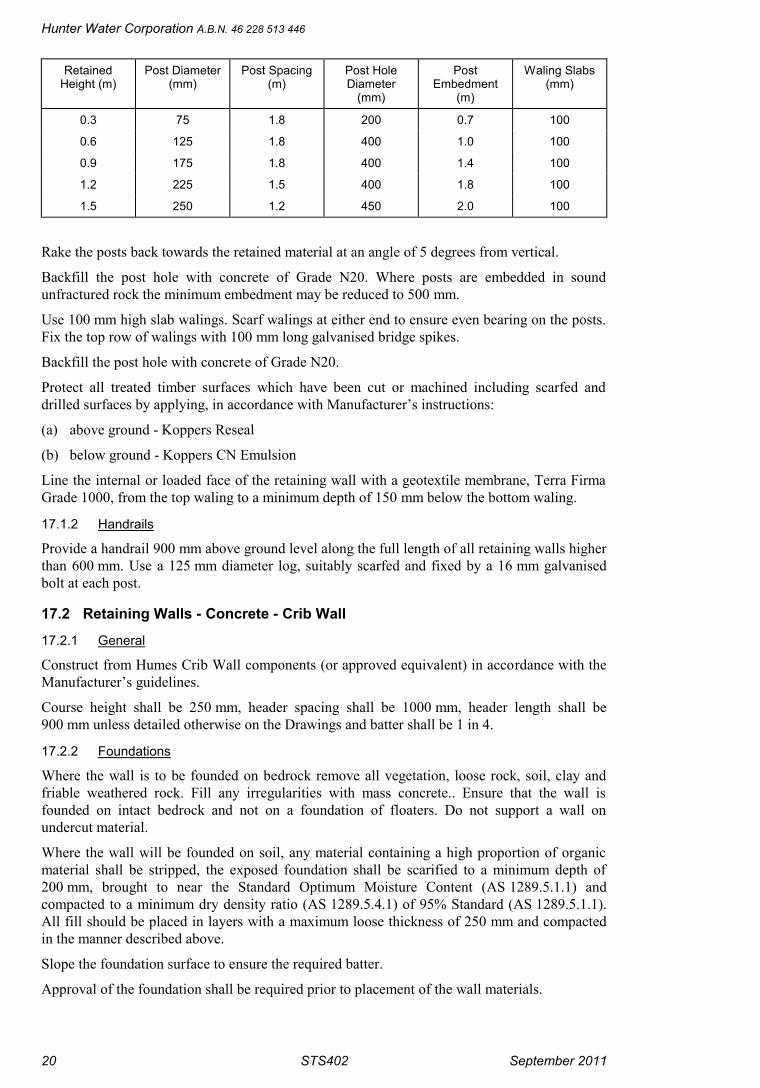
Where details are not shown on the Drawings dimensions shall be in accordance with thefollowing table:
Hunter Water Corporation A.B.N. 46 228 513 446
20 STS402 September 2011
RetainedHeight (m)
Post Diameter(mm)
Post Spacing(m)
Post HoleDiameter
(mm)
PostEmbedment
(m)
Waling Slabs(mm)
0.3 75 1.8 200 0.7 100
0.6 125 1.8 400 1.0 100
0.9 175 1.8 400 1.4 100
1.2 225 1.5 400 1.8 100
1.5 250 1.2 450 2.0 100
Rake the posts back towards the retained material at an angle of 5 degrees from vertical.
Backfill the post hole with concrete of Grade N20. Where posts are embedded in soundunfractured rock the minimum embedment may be reduced to 500 mm.
Use 100 mm high slab walings. Scarf walings at either end to ensure even bearing on the posts.Fix the top row of walings with 100 mm long galvanised bridge spikes.
Backfill the post hole with concrete of Grade N20.
Protect all treated timber surfaces which have been cut or machined including scarfed anddrilled surfaces by applying, in accordance with Manufacturer’s instructions:
(a) above ground - Koppers Reseal
(b) below ground - Koppers CN Emulsion
Line the internal or loaded face of the retaining wall with a geotextile membrane, Terra FirmaGrade 1000, from the top waling to a minimum depth of 150 mm below the bottom waling.
17.1.2 Handrails
Provide a handrail 900 mm above ground level along the full length of all retaining walls higherthan 600 mm. Use a 125 mm diameter log, suitably scarfed and fixed by a 16 mm galvanisedbolt at each post.
17.2 Retaining Walls - Concrete - Crib Wall
17.2.1 General
Construct from Humes Crib Wall components (or approved equivalent) in accordance with theManufacturer’s guidelines.
Course height shall be 250 mm, header spacing shall be 1000 mm, header length shall be900 mm unless detailed otherwise on the Drawings and batter shall be 1 in 4.
17.2.2 Foundations
Where the wall is to be founded on bedrock remove all vegetation, loose rock, soil, clay andfriable weathered rock. Fill any irregularities with mass concrete.. Ensure that the wall isfounded on intact bedrock and not on a foundation of floaters. Do not support a wall onundercut material.
Where the wall will be founded on soil, any material containing a high proportion of organicmaterial shall be stripped, the exposed foundation shall be scarified to a minimum depth of200 mm, brought to near the Standard Optimum Moisture Content (AS 1289.5.1.1) andcompacted to a minimum dry density ratio (AS 1289.5.4.1) of 95% Standard (AS 1289.5.1.1).All fill should be placed in layers with a maximum loose thickness of 250 mm and compactedin the manner described above.
Slope the foundation surface to ensure the required batter.
Approval of the foundation shall be required prior to placement of the wall materials.

Construction of Submersible Sewage Pumping Stations
September 2011 STS402 21
Where the wall is to be founded on bedrock, the base of the wall shall be at a level which is aminimum depth of 250 mm below the finished surface level at the toe of the wall.
Where a wall, is to be founded on soil, the base of the wall shall be at a level which is aminimum depth of 450 mm below the finished surface level at the toe of the wall.
Provide a continuous base of 250 mm thick S32 concrete reinforced with 2 layers of F81 fabric.Step the base where required in increments of 250 mm.
Where pipes are to pass beneath the wall they shall be encased in concrete.
17.2.3 Cribfill and Backfill
Use crushed rock with maximum particle size 75 mm for fill material in the wall (Cribfill).
Use granular material consisting of sand, crushed rock, slag, skulls, ripped sandstone forbackfilling behind the wall.
Do not use clay material as fill material in the wall or backfill material within 500 mm of therear of the wall.
Compaction of fill placed behind the wall shall be carefully carried out to minimise the inducedlateral stress against the wall.
Place fill in layers with a maximum loose thickness of 250 mm and compact to a dry densityratio (AS 1289.5.4.1) of not less than 95% Standard Compaction (AS 1289.5.1.1).
Where pavement construction is to take place using the backfill as subgrade material, compactin accordance with the requirements of clause 16.2.
17.2.4 Drainage
Install a 160 mm diameter subsoil drain with filter sock at the rear of the wall foundation.
Direct all surface runoff away from the back of the wall so as to prevent infiltration of suchsurface runoff into the granular backfill. Direct the surface runoff so as to prevent erosion andpossible undercutting along the toe of the wall. Ensure that water does not pond at the toe of thefinished wall.
17.2.5 Handrail
Provide a handrail 900 mm above ground level along the full length of all retaining walls higherthan 600 mm. Construct the handrail from Koppers Tanalith logs to AS 1604 with post spacing,post diameter, post embedment and rail diameter as shown on the Drawings. Use Brand No. H5logs to the requirements of AS 1604 Hazard Level 5 protection. Suitably scarf the rails and fixat each post with a 16 mm galvanised bolt.
Where details are not shown on the Drawings dimensions shall be in accordance with thefollowing table.
Post Diameter(mm)
Post Spacing(mm)
Post HoleDiameter (mm)
PostEmbedment
(mm)
Rail Diameter(mm)
125 1800 400 1000 125
Backfill the post hole with concrete of Grade N20.
Protect all treated timber surfaces which have been cut or machined including scarfed anddrilled surfaces by applying, in accordance with Manufacturer’s instructions:
(a) above ground - Koppers Reseal
(b) below ground - Koppers CN Emulsion
Hunter Water Corporation A.B.N. 46 228 513 446
22 STS402 September 2011
18. RESTORATION
18.1 GeneralRestore as near as practicable to their pre-existing condition, all surfaces, services and/orimprovements disturbed, destroyed, removed or damaged during construction of the Works andduring installation of temporary works such as access roads. Improvements shall be deemed toinclude trees and shrubs, mulched areas, gardens, paving, flagging, proprietary finished areassuch as 'pebble crete' and the like, retaining walls, fences and all other structures.
When necessary for the restoration of surfaces, stockpile existing topsoil separately and replaceit over the areas where it was previously located when completing backfilling operations.Where there is a shortfall of existing topsoil use approved imported topsoil.
18.2 Timing of RestorationUndertake restoration to surfaces, services and improvements progressively as the workproceeds. At all times ensure that services are maintained. Complete restoration and repairwork within five calendar days after completion of backfilling of each section of the Worksunless specifically stated otherwise elsewhere.
Undertake any maintenance of the restoration within two calendar days of the need for suchmaintenance becoming apparent.
18.3 PavementsImmediately after backfilling of a trench excavated through a pavement, temporarily restore thesurface and maintain it in a trafficable condition until final restoration is completed. Where theoriginal pavement was bitumen or asphalt use a pre-mixed asphaltic material for the temporaryrestoration. Otherwise use crushed metal or gravel. Complete final restoration of pavementswithin one month of temporary restoration.
18.4 TurfRestore areas of established well maintained lawns to the full limits of the disturbed area withapproved imported turf. Restoration using sods removed prior to construction will only beapproved if the sods are of equivalent standard to imported turf. Also use turf to restore areaswhere there is significant risk of erosion such as on steep or long slopes.
Following backfilling and initial settlement spread and grade topsoil to achieve a smoothsurface free from lumps, stones or other debris and blending into the levels and shapes of theadjoining undisturbed ground allowing for the turf. Mix an approved fertiliser of N:P:K ratio of10:4:6 (equivalent to "Mulitgro") into the topsoil at a rate of 40g/m2.
Lay the turf without gaps on the prepared topsoil surface and lightly top dress and compact.Water regularly until regrowth is established.
18.5 Grassed AreasFor grassed areas not requiring restoration with turf, restore by replacing the pre-existingtopsoil or approved imported topsoil, to a minimum thickness of 50 mm. Seed the affected areawith grass seeds of the varieties prevalent in the immediate area. Water and maintain thedisturbed area until regrowth is established.
If regrowth fails to occur within six weeks of restoration, reseed and maintain until regrowth isestablished.
18.6 TreesWhere Council or private landowners require replacement trees to be planted, provide suitabletrees. Where such replacement trees will be adjacent to a sewer, provide trees suitable forplanting adjacent to the sewer as detailed in Hunter Water Corporation's publication entitled"Tree Roots’.
Construction of Submersible Sewage Pumping Stations
September 2011 STS402 23
18.7 Provision for SettlementMake good any settlement of the trench during the Defects Liability Period by placingadditional approved fill such that the finished surface level conforms with the adjacent surface.
For trenches through other than pavements, turf areas, grassed areas or other improved surfaces,backfill may be placed sufficiently high to compensate for expected settlement unless it wouldcreate a hazard or inconvenience to the public. At the end of the Defects Liability Period, trimback such excess material to conform with the adjacent surface and dispose of the surplus.
18.8 TunnellingWhere tunnelling has been used in lieu of trenching to avoid improved surfaces, backfill suchas to restore full support to the surface. Repair any damage to the improved surface whichoccurs at anytime due to subsidence of the backfill.
18.9 Maintenance of Restored SurfacesMaintain all restored surfaces and improvements in a satisfactory condition until expiry of theDefects Liability period notwithstanding that any deterioration, and the need for theirmaintenance, may or may not be due to defects which become apparent or arise from eventswhich occur during that period.
18.10 CertificationSubmit certificates issued by the relevant public authorities certifying that all roads, footpathsand surfaces in public places under their control have been satisfactorily restored.Notwithstanding any other provision, the Defects Liability Period shall not be completed untilsuch certification is submitted unless it is agreed that the public authority has unreasonablywithheld issue of the certificate. The issue of such certificates shall not relieve anyresponsibility for any defect.
19. CONNECTION TO EXISTING SEWERAGE SYSTEMOnly undertake connection to existing live sewerage system on completion of all other Works.Give written notice, including full details of the proposed connection procedures, 10 workingdays prior to making the connection and comply with any directions regarding the method andtiming of the connection which are necessary to meet operational needs of the existing sewersystem.
Perform the connection on the approved date and at the approved time. Do not commence theconnection work unless all necessary materials and equipment are available on site. Undertakeall work so as to minimise interruption to the operation of the existing sewer system and toprevent overflow of sewage. Escape of sewage from the live system shall not be tolerated. Ifnecessary pump sewage around the point of connection.
20. ACCEPTANCE TESTING
20.1 GeneralUndertake acceptance testing of the pumping station wet well, valve pit, overflow structuresand all pipelines constructed. Acceptance testing may be done progressively, but must be noearlier than 7 days after completion of the structure or pipeline section to be tested. Give 48hours notice before commencement of acceptance testing. Ensure that structures and pipes areclean before any test is performed. Do not pressure test during wet weather.
If any of the tests prove to be unsatisfactory, detect and repair the fault and then re-test.Continue to repair and re-test until a satisfactory test is obtained. Even if testing producessatisfactory test results, repair any structure, pipeline or conduit in which there is a visible ordetectable leak or blockage.

Hunter Water Corporation A.B.N. 46 228 513 446
24 STS402 September 2011
20.2 Acceptance Testing of Gravity PipelinesTest all gravity pipelines including all overflow pipework and the inlet pipework from thecollecting access chamber to the wet well in accordance with clause 22 of WSA02 Part 3Hunter Water Edition.
20.3 Acceptance Testing of Pressure PipelinesTest all pressure pipelines including the discharge pipework from the pump discharge bend tothe connection point to the rising main in accordance with clause 19 of WSA03 Part 3 HunterWater Edition.
20.4 Testing of Pumping Station Wet Well
20.4.1 General
Test the pumping station wet well for leakage as soon as practicable after it has beenconstructed. Plug all pipe openings in the walls with the plugs placed in the pipes as near aspracticable to the internal face of the well.
Use an exfiltration test unless it can be demonstrated that ground water is at a sufficiently highlevel to ensure that all construction joints and pipe penetrations can be adequately tested by aninfiltration test.
20.4.2 Exfiltration Test
Fill the well totally with water and after allowing an interval for absorption of 4 hours refill thewell and measure the loss of water during a period of 30 minutes.
The test will be considered satisfactory provided that water loss is less than 2 mm depth foreach 1 m depth of well. The depth of well is measured from the underside of the roof slab to thewell floor.
20.4.3 Infiltration Test
Where the pumping station wet well is subjected to a significant head of ground water, theSuperintendent may order that the hydrostatic test on the wet well be by visual inspection andmeasurement of infiltration.
If the Superintendent requires a visual inspection and infiltration test the Superintendent shalldetermine the duration over which infiltration is to be measured, and the amount of infiltrationallowable for a satisfactory test.
21. COMMISSIONING OF PUMPING STATION
21.1 RequirementsAll materials, equipment, installation and workmanship included in the Works covered by thisSpecification shall be tested and/or inspected to prove compliance with the Specificationrequirements.
Tests and inspections shall comply with current relevant Australian Standards.
Testing shall include pre-commissioning, field testing and performance testing of each part ofthe whole installation.
21.2 Pre-commissioningPre-commissioning is the preparation of plant or equipment so that it is in a safe and propercondition and ready for commissioning and operation. It includes all aspects of plant operationsuch as safety, electrical, mechanical and instrumentation.
Pre-commissioning shall be conducted in a logical sequence in accordance with Appendix A -Pre-Commissioning Checklist.

Construction of Submersible Sewage Pumping Stations
September 2011 STS402 25
Pre-commissioning tests shall be carried out under the Supervision and to the satisfaction of theHunter Water Corporation and shall be recorded on the appropriate Pre-commissioningChecklist.
Prior to Commissioning submit one signed copy of each completed Pre-commissioningChecklist countersigned by the Hunter Water Corporation's Representative who witnessed thetest.
21.3 CommissioningCommissioning is the running of the plant and equipment to ensure flow through the pumpingsystem, carrying out any necessary testing and adjustments until it is ready and suitable fornormal starting and running under service conditions.
Representatives of the Hunter Water Corporation will participate in the tests and may elect torecord an independent set of test results for evaluation. The Hunter Water Corporation shallrequire a period of ten (10) working days notice to undertake testing.
Commissioning shall be conducted in a logical sequence in accordance with Appendix B -Commissioning Checklist.
Throughout commissioning the Contractor shall be responsible for the test program.
Provide continuous supervision by personnel experienced in the operation of the equipment andhave qualified personnel in attendance to carry out all necessary adjustments and/or remedialwork during the commissioning tests.
Submit one signed copy of each completed Commissioning Checklist countersigned by theHunter Water Corporation's Representative who witnessed the test. Provision of completedCommissioning Checklists is a prerequisite of Practical Completion.
22. WORK-AS-CONSTRUCTED DETAILSProvide Work-As-Constructed details in accordance with STS903, STS904 and STS911 at leastten (10) working days prior to the date of commissioning.
23. OPERATION AND MAINTENANCE INFORMATION
23.1 ManualsClause 23.1 applies if no Operation and Information Package has been provided by HunterWater Corporation.
Provide four (4) copies of Operations and Maintenance Manuals including lubrication chartsand trouble-shooting instructions for the whole of the equipment including soft starters if used.Submit Operations and Maintenance Manuals to the Superintendent at least ten (10) workingdays prior to the date of commissioning.
The installation, operation and maintenance instructions must be relevant to the actualmachinery supplied under this Contract. Identify all parts requiring maintenance and clearlystate the type and frequency of recommended maintenance. Installation, operation andmaintenance instructions that are of a general nature are not acceptable.
Each copy must be assembled between a set of durable hardcovers suitably labelled andsecurely fastened. The method of binding must provide a secure system of fastening pages andallow manuals to lay open whilst in use and permit pages to be easily replaced and / or added.
In addition to the requirements set out above the manuals shall include:-
(a) General
Contractors name, address and telephone number

Hunter Water Corporation A.B.N. 46 228 513 446
26 STS402 September 2011
Client contract number
Job name
Pumping station general arrangement drawing of pumps, motors and pipework.
Work as Constructed electrical installation drawings prepared in accordance withclause 26.7.
(b) Pumps
Manufacturer
Type and model number
Serial numbers
Typical performance curves
General arrangement drawing of pump and discharge bend assembly (dimensioned)
Section arrangement drawing with parts and material list.
(c) Motors
Manufacturer
Type and model number
Serial numbers
Dimensioned arrangement drawing
Sectional arrangement drawing with parts and material list
Gland sealing arrangement drawing for submersible motor power cables
(d) Test Curves (where applicable)
Pump certified test curves
Test result log sheet
Motor test curves
Motor torque/speed/efficiency characteristics curves
(e) A Description of Operation
(f) Installation Instructions
(g) Start Up/Shut Down Procedures
(h) Maintenance Information
Trouble shooting instructions for pump and motors.
Step by step procedures for dismantling and reassembly of pumps and motors usingany special tools shall be detailed together with step by step procedures forreplacement of wearing parts such as bearings, seals, wear rings, etc.
Drawings as scheduled and any other drawing necessary for complete understandingof installation, operation and maintenance.
Log sheets and maintenance inspection sheets for use by operations and maintenancestaff detailing routine monitoring, inspection and maintenance requirements andfrequency thereof.
(i) PLC Information
Copy of PLC program and Label File on 3 ½” Disk
Program Documentation

Construction of Submersible Sewage Pumping Stations
September 2011 STS402 27
23.2 Information PackageClause 23.2 applies if an Operation and Information Package has been provided by HunterWater Corporation.
The electronic Operation and Information Package provided lists all of the information requiredto allow the ongoing operation and maintenance of the Works. Some of the requiredinformation has been prepared by the designers and is included in the package.
Prepare all of the information indicated in the package to be provided by the 'InstallationContractor', append it to the package in the form indicated, and submit the complete package atleast ten (10) working days prior to the date of commissioning.
24. GENERAL ELECTRICAL WORKSAll telemetry and automation, electrical installation and switchboard manufacture work is to beperformed by companies approved to do so by Hunter Water Corporation.
Comply with the Hunter Water Corporation's General Requirements for Electrical InstallationsSTS500..
Arrange for each Authority having jurisdiction to inspect and check the works.
25. MANUFACTURE AND SUPPLY OF ELECTRICAL EQUIPMENT
25.1 Equipment RatingEquipment ratings shown on schedules or drawings are estimates only. Confirm the actualequipment ratings to of the supplied equipment including motor starters and cabling. Where therating exceed the drawing values the Contractor shall be responsible for determining therequired ratings of equipment and cables.
25.2 Provision of PlinthsConstruct the cabinet base 25 mm smaller than the concrete plinth on all sides.
25.3 Switchboards
25.3.1 Circuit Breakers
The service protection circuit breaker shall, as a minimum, be fitted with an electronic controlunit, have adjustable thermal, magnetic and instantaneous pickups as well as adjustable timedelays for thermal and magnetic pickups. It shall discriminate with the supply authority fuses.
The motor circuit breakers are to be selected to discriminate with the service protection deviceand provide sufficient current for the pumps to start at a minimum of 4 times full load current
25.4 Control Circuit WiringBush all metal edges in contact with cables.
Cable primary insulation shall be coloured in accordance to STS500
Seek direction on colour coding for voltages other than those listed in STS500.

Hunter Water Corporation A.B.N. 46 228 513 446
28 STS402 September 2011
25.5 Equipment MountingMount all items of equipment using metric, zinc plated metal thread set screws, screwed intotapped holes. Mount small items such as relays and miniature circuit breakers on DIN35mounting rail.
Terminal mounting rail, DIN35 mounting rail and plastic wiring duct, may be secured by selfdrilling/threading screws.
Do not use self tapping screws.
Provide a minimum of 25 mm between the terminal side of all relays and equipment and theadjacent wiring duct or equipment, to facilitate wiring.
Do not mount any equipment in front of other equipment.
Do not locate terminals within 250 mm of the base of the cubicle or 300 mm of the top of thecubicle.
Locate mains and motor terminals such as to provide easy access to outgoing terminations, withcable holes clearly visible.
25.6 TerminationsProvide suitably rated power terminal blocks in the switchboard for the termination of theincoming field wiring. Provide control terminal blocks, minimum size 10 amps, in each cubiclefor the termination of the incoming field wiring. Provide a separate terminal for every fieldcable core including spare cores. Terminate each core within a cable in consecutive terminals.
Terminate control wiring, at each end, with a pre-insulated crimp lug or cable crimp sleeve.
Where two control wires are to be terminated in a single tunnel terminal, twist both wirestogether and crimp in a common crimp sleeve designed for the purpose.
Crimp all crimp sleeves and crimp lugs to the wire ends with a tool having a ratchet device toensure full crimping before tool will release. Do not use crimp tools without ratchet devices,pliers or similar blade tools to secure sleeves or lugs to wires.
The entire metal surface of any crimp sleeve or lug shall be contained within the terminalshrouding and shall not be visible.
Do not use pin or blade type crimp lugs in tunnel type terminals.
25.7 Equipment Requirements
25.7.1 Compliance
Select equipment from Hunter Water Corporation's lists of Approved Products andManufacturers which can be accessed on the internet at:
http://www.hunterwater.com.au/Building-and-Development/
Where suitable equipment is not listed, submit full technical details of alternative items andobtain written approval prior to use.
Provide proof of compliance with the relevant Australian Standard if requested. Such proofshall comprise a complete Test Certificate from an accepted independent Testing Authority or aCertificate of Suitability issued by an Australian Electricity Authority.
25.7.2 Equipment Supplied by Others
Obtain the kWh Metering Equipment direct from the Supply Authority.
25.7.3 Equipment Supplied by Others at the Contractor’s expense
Lock Barrel - obtain from Hunter Water Corporation Ltd.

Construction of Submersible Sewage Pumping Stations
September 2011 STS402 29
Notify the Hunter Water Corporation a minimum of fifteen (15) working days prior to requiringthe 81/3 lock barrels.
The installation of HWC locks is the responsibility of the contractor.
25.8 Labelling
25.8.1 General
For each starter attach the pump and motor nameplate to the starter inner door. These are tomatch the nameplates attached to the pump
Clearly and accurately label every item of equipment within or on the switchboard.Provide alabel, mounted adjacent to each fuse base, engraved with the fuse element rating.
STS500 and the design drawings provide further specific details of labelling requirements.
External labels are to be manufactured from the same material as the switchboard, egAluminium sheet for Aluminium switchboards.
25.8.2 Asset and Equipment Number Labels
Supply and install Equipment Number Labels as listed in APPENDIX C and manufacturedfrom materials as detailed in clause 4.23. Fix labels as follows:
(a) Station Equipment Number Label - Fix, using four (4) aluminium pop rivets, to thefront of the switchboard cabinet above main labels and positioned such that it can beeasily seen from the access driveway.
(b) Pump Equipment number Labels - Circuit Breaker - Fix permanently adjacent to therespective circuit breaker using double backed adhesive mounting tape.
25.9 Programming of Logic ControllerProgram all Programmable Logic Controllers to suit the operation and control requirements ofthe installation.
Obtain the sample PLC software from the Hunter Water Corporation.
Develop, prepare, install and commission PLC software to suit the pump station.
Assign all rights of the software prepared for this Contract to the Hunter Water Corporation.
25.10 Final Inspection and TestBefore delivering each switchboard to site the switchboard must satisfy the tests required inSTS500 including at least the following:
(a) Insulation test of all power wiring with 1000 V insulation tester, tested phase to phaseand neutral, phase to earth, neutral to earth.
(b) For switchboards containing busbars, a 2.5 kV high potential test with minimum5 mA leakage current followed by repeat of test (a) above. Report any leakage currentor change in insulation resistance.
(c) Test and record earth continuity of earth busbar and earthing conductors.
(d) Test all protection equipment and motor protection relays by secondary injection ofthe current transformer circuits.
(e) Test phase fail, phase reversal relays with correct and reversed phase sequence toensure correct operation. Also test relay by removing one fuse.
(f) Test operation of all Residual Current Device (RCD) circuit breakers and combinedResidual Current Device/General Purpose Outlet (RCD/GPO) units. Units shall tripwhen leakage exceeds 30 mA.
(g) Test voltmeter and voltmeter selector switch for correct voltage indication.
Hunter Water Corporation A.B.N. 46 228 513 446
30 STS402 September 2011
(h) Test each motor starter for correct operation with all other drives and equipmentturned off. Test shall include operation of thermal overload, phase failure, overtemperature devices, etc, with starter selected for both manual and automaticoperation. Test operation of all indicating lamps and control devices.
(i) Test motor starter with load connected and observe ammeter movement. Check forhigh resistance connections.
(j) Test each Programmable Logic Controller input from the connected device and ensurecorrect operation.
(k) Test each Programmable Logic Controller output and ensure correct operation ofconnected devices.
(l) Test operation of level control systems by simulation of changing level on primarydevice.
(m) Test operation of instrument loops by simulation of primary device.
(n) Configure starter parameters
(o) Configure circuit breaker settings
(p) Simulation testing of Programmable Logic Controller.
(q) Check that the Duty and Standby pumps alternate their duty upon each operation.
Give at least five working days notice before the final inspection is performed prior to deliveryto site.
Within three working days of the inspection submit a signed completed copy of the results ofthe inspection.
25.11 Delivery and StorageDeliver the switchboards to site undamaged in any way.
25.12 Site TestingAfter the switchboard has been installed, perform tests to verify the performance under siteconditions and to ensure performance of all equipment is satisfactory.
26. INSTALLATION OF ELECTRICAL EQUIPMENT
26.1 Supply Authority RequirementsMake all necessary applications and submissions to the Supply Authority. Forward theCustomer Copy of all forms to the Superintendent.
26.2 Installation of Submersible Pump Cables
26.2.1 Location of Pumps
Pump number 1 shall be closest to the switchboard. Pumps are numbered in sequence fromnumber 1 including future pumps not currently installed ie. where centre pump of a threepumping station is not installed, pumps are connected to Pump 1 and Pump 3 starters.
26.2.2 Installation
Pump cables are to be supported at the top of well with individual stainless steel cablestockings for each cable. Each stocking shall support only one cable. Support the cable stockingfrom the cable support bracket opposite the respective pump.
Do not cut or shorten flexible cables attached to submersible pumps, level probes or levelregulators more than necessary. Where able to fit and maintain cable rating, coil excess cableneatly in the space beneath the junction box.

Construction of Submersible Sewage Pumping Stations
September 2011 STS402 31
Support pump cables so that no undue bending or stress is evident at motor cable glands.
26.3 Installation of Level Sensors
26.3.1 Level Probe
Support each level sensor probe and each high level float switch with stainless steel cablestockings attached to a grade 316 stainless steel hook. Supply one hook per instrument. Theinstrument hooks supplied shall be as shown on SCP-906 (referred to as B-906 chain hook).
Locate the probe is so that is no closer than 300 mm to any equipment in the well. Install thesupport hook with 6 mm diameter stainless steel masonry anchors fixed into the side of the roofopening. Mount the bracket such that the fixing holes are closest to the top of the bracket.
Mount the float switch at the alarm level as shown on the Drawings and capable of beingadjusted 1 metre above or below this level.
26.4 Installation in Pump Well
26.4.1 General
All areas in the wet well and valve pit are classified as a wet situation and are subject to a highlevel of corrosion.
All supports and fasteners used and installed in pump well or valve pit shall be manufacturedfrom grade 316 stainless steel or approved non-corrosive products.
Do not use brass, mild steel, electro-plated mild steel, within the wet well or valve pit.
Place Insulating washers between any dissimilar metals to reduce corrosion due to electrolysis.
26.4.2 Cables
Install cables away from pumps and in a location which allows raising and withdrawal of anypump without disturbing the cabling to other pumps or equipment in the well.
Do not install pump cables behind pump guide rails without prior written approval.
26.5 TestingCarryout all tests and verification as required by AS3000, particularly Section 8. Provide achecklist confirming each test in Section 8 has been undertaken and completed successfully.The checklist is to be signed by the certifying officer on behalf of the contractor. Include thesetest documents in the Operation and Maintenance Manual. Submit the completed checklist tothe Superintendent at least 5 days before Pre-commissioning.
.
Submit, within three days of completion of any site tests, reports of all tests and inspections.
Tests shall include but not be limited to
(a) Insulation resistance of Consumer's Mains and motor cables. Resistance shall begreater than 30 M ohm, measured with a 1000 V insulation tester.
(b) Phase rotation check on Consumer's Mains. Rotation shall be Red - White - Blue.
(c) Check supply voltage phase to phase and phase to earth. Voltage variation betweenphases shall not exceed two percent (2%).
(d) Test resistance of motor thermistors (if installed), with a high impedance multimeter.Thermistor resistance shall be between 150 and 600 ohms.
(e) Test the Vega level sensor by immersing the sensor or simulate a water level betweenzero and full span value ensuring output current varies between 4 and 20 mA. Alsoensure level display readings are correct for depth of immersion.

Hunter Water Corporation A.B.N. 46 228 513 446
32 STS402 September 2011
(f) Test operation of high level float switch with a high impedance multimeter.Disconnect circuit from the Telemetry module prior to testing.
(g) General inspection of the completed installation for compliance with thespecification.
26.6 Notification of Electrical WorkMake all applications and submissions to Energy Australia necessary to allow construction andcommissioning of the Works. Submit copies of all forms to the Superintendent.
.
26.7 Work As Constructed Drawings and SchedulesPrepare Work-as-Constructed (WAC) Information in accordance with Hunter Water’s StandardTechnical Specification STS903 and STS904 as applicable
Not withstanding that part/s of the WAC have been previously submitted, such as with O&MInformation prior to Commissioning, submit for review two hard copies and one electroniccopy (CD) of the complete WAC Information for the entire contract at least four weeks prior toPractical Completion.
The Superintendent may provide comments within 3 weeks of the submission.
Make appropriate amendments and submit one hard copy and one electronic copy (CD) of thefinal WAC Information which complies with the Contract.
Submission of the complying WAC Information for the entire contract is a prerequisite forPractical Completion.
.
27. AUTOMATION AND TELEMETRYDesign, install and commission the PLC, SCADA and telemetry system for the control andmonitoring of the stations. Hunter Water shall provide a template program as the basis for thePLC program. Modify this program to suit each particular station. The PLC program shallcontain code to support all required functions of the control system as defined in the FunctionalSpecification. Fully document the PLC program in accordance with AS 3876.
Configure Hunter Water’s SCADA database to allow remote control and monitoring includingthe following work:
- configure the RTU;
- configure the database points associated with the RTU and consistent with thoserequired for the particular station type;
- make necessary additions/alterations to the SCADA pages;
- add the necessary SCADA points; and
- update the SCADA system network diagrams.
Submit draft SCADA pages to the Superintendant for review and comment 3 weeks priorto pre-commissioning.
Program any switches or devices as necessary to complete the works.

Construction of Submersible Sewage Pumping Stations
September 2011 STS402 33
28. SUBMERSIBLE MOTOR TYPE SEWAGE PUMPS
28.1 Selection of Pump UnitsObtain pumps from approved manufacturers/suppliers as indicated on Hunter WaterCorporation's lists of Approved Products and Manufacturers which can be accessed on theinternet at:
http://www.hunterwater.com.au/217.aspx
Unless the pump brand and model number has been specified elsewhere, select the mostappropriate pump unit which meets all specified requirements at lowest life cycle cost.
28.2 Operating Requirements
28.2.1 Operating Range
The pumping units shall operate satisfactorily between maximum and minimum pipelinecharacteristics and down to flood minimum head without exceeding a current in any motorcable equivalent to 95% of the motor MCR current under the specified supply conditions.
The pumping units shall have steadily falling Head/Quantity curves from no-flow to flow rates10% in excess of the flood head flow rates.
The pumps shall normally operate singly however shall be capable of operating in parallelunless otherwise specified.
28.2.2 Pipeline Characteristics
The pipeline characteristics are plotted as a graph - refer to "Graph of Pipeline Characteristics"included in Appendix D.
28.2.3 Pump Duty
Pump duties are shown in the Technical Schedule TSSS 3/81 - Extract Sheets.
The best efficiency point for each pump shall be as close as possible to the specified duty pointunless otherwise specified.
The pump performance guarantee figures stated in Technical Schedules TSSS 3/81 ExtractSheets shall refer to system minimum head condition.
28.3 Pump Unit Requirements
28.3.1 General
The pumping units shall comply with the requirements set out in the Pumping Station GeneralArrangement Drawing.
The pumping units shall be current models which have been in successful operation undercomparable conditions for at least two years.
Clearly and permanently mark the direction of pump rotation on the pump casing.
Impellers to have a minimum sphere clearance of 76 mm.
28.3.2 Mechanical Seals
The seals shall be suitable for sewage and fluids containing abrasives.
Double mechanical seals are required, preferably arranged in tandem. In tandem, the lower sealin the product field shall be shielded.
Use either single or multiple springs for shaft sizes of 100 mm or less. Use multiple springs forshaft sizes greater than 100 mm.
Secondary seals shall be O-ring or similar.
Seal materials shall be as follows:
Hunter Water Corporation A.B.N. 46 228 513 446
34 STS402 September 2011
(a) Lower or Product Seal
Rotating Seal Face: Tungsten Carbide or Silicon Carbide
Stationary Seal: Tungsten Carbide or Silicon Carbide
Springs: Nickel Chrome Steel
Secondary Seal: Fluoro Carbon or Nitrile Rubber
(b) Upper or Motor Seal
Rotating Seal Face: Carbon or Tungsten Carbide
Stationary Seal: Tungsten Carbide
Springs: Nickel Chrome Steel
Secondary Seal: Fluoro Carbon or Nitrile Rubber
Lap the seal interfaces. The depth of interface roughness shall be less than 0.3 mm and flatnessshall be within two (2) light bands.
Provide pressure compensation for the oil in the seal chamber.
Fit a seal failure detection device to the seal housing with connections thereto from the motorhousing. Externally connected devices are not acceptable.
28.3.3 Discharge Connection and Guide Bars
The discharge connection shall be arranged such that coupling and uncoupling of the pumpshall be accomplished by raising and lowering the pump through a straight vertical lift.
The pump shall be automatically guided to the discharge connection by a system of guide barswhich will ensure correct seating and sealing of the pump and discharge connection. Arrangethe guide bars so as to prevent binding of the pump whilst it is being raised or lowered.
Secure the guide bars in such a manner as to allow removal of the pump from the stationwithout dismantling any part of the pump or guide bar system.
Guide bars and brackets shall be constructed from Grade 316 stainless steel.
Provide Grade 316 stainless steel intermediate guide bar brackets if necessary to ensure rigidityand where unsupported length of bar exceeds 6 metres.
28.3.4 Lifting Chains
Supply lifting chains for installation and removal of the pumps.
The chain shall be a continuous length, sufficient to enable removal of the pump from the well,with a lifting eye attached to the top of the chain with a shackle (or forged into the top chainlink) to enable the pump to be raised and large enough for a sling or crane hook. Attach asecond lifting eye 1.5 metres below the top eye.
Shackle the other end of the chain to the pump lifting bridle.
Chain including lifting eye and shackles is to be load rated for lifting. Select the link size,lifting eye and shackle in accordance with the manufacturer's recommendations for the mass ofthe pump.
The lifting eyes shall have a minimum throat opening of 150 x 100 mm.
The lifting chains, lifting eyes and shackles shall be minimum 8 mm diameter Grade 316stainless steel.
28.3.5 Holding Down Bolts
Secure the Discharge Bend, Guide Bars, Cable Support Hooks and Chain Support Hooks usingholding down bolts, nuts and washers manufactured from stainless steel to AS 2837 Grade 316and fastened into the concrete using chemical adhesive anchors. Fasteners subject to vibration

Construction of Submersible Sewage Pumping Stations
September 2011 STS402 35
shall be provided with locking devices. For pump discharge bends use large series washers andholding down bolts of sufficient length for three full threads to protrude from the nut wheninstalled.
28.3.6 Lifting Bridle
Fit a 316 stainless steel lifting bridle to each pump. The bridle shall be able to support the fullworking weight of the motor / pump set and be capable of accepting a crane hook 150 mm deepin section.
Ensure that when lifting either by chain or directly by crane hook, the weight distribution of themotor / pumpset will aid in seating and unseating of the pump from it’s pedestal.
28.3.7 Hatch Openings and Guide Brackets
The dimensions of the hatch opening and the pump spacings on the General ArrangementDrawings have been determined by Project requirements and the Contractor is to nominatepump locations and is to provide guide rail brackets to suit this opening. The brackets fixing theguide rail to the face of the hatch opening shall be designed to give a minimum clearance of76 mm between the pump sliding bracket and the safety screen support angle to preventinterference on pump withdrawal. Fabricate any extension to the guide rail brackets using10 mm minimum thick Grade 316 stainless steel plate. All bolted connections shall be by M12minimum stainless steel screwed rod fastened into the concrete with chemical adhesiveanchors.
28.3.8 Pumping station Arrangement
Tenderers are required to submit details of any necessary alterations to the wet wellarrangements shown on the drawing(s) required to ensure satisfactory hydraulic performance ofthe Pumps tendered. Acceptance of the tendered pumps is conditional that they are suitable tothe well arrangement as detailed unless alterations have been noted by the Contractor andaccepted with the tenderer.
28.3.9 Pump Numbering
The pump with the lowest serial number shall be the No 1 pump and shall be installed closest tothe electrical switchboard.
28.3.10 Pipes and Fittings
Where the outlet flange of the discharge bend is of a different size to the vertical riser pipeworkinside the well as shown on the drawing, supply flanged eccentric tapers.
28.3.11 Nameplate
Attach a stamped or embossed stainless steel nameplate to each pump using stainless steel drivescrews. Do not paint.
Nameplate details shall include manufacturer's name, pump type, size, serial number,order/contract number, speed, year of manufacture and pump casing test head.
28.3.12 Protective Coatings
The pumps and discharge bends shall be supplied with painted finish to the pumpmanufacturer’s standard coating or the following alternative:- grit blast to AS 1627 Part 4 Class3 and paint in accordance with the paint manufacturer’s instructions to a thickness of 500microns with a high build solventless epoxy coating approved under the APAS scheme. Referclause 8.2.
28.3.13 Galvanising
Where items are required to be galvanised, the process to be employed shall be hot dipgalvanising and the provisions of AS 1650 shall apply subject to the additional requirements forheavy galvanising specified below. AS 1214 and the relevant requirements of AS 1650 shallapply to galvanising of fasteners such as bolts, nuts and washers.

Hunter Water Corporation A.B.N. 46 228 513 446
36 STS402 September 2011
Where applicable, galvanise after fabrication. Prior to pickling and galvanising, remove weldslag and weld spatter by mechanical means.
Provide enclosed hollow sections with vent and drainage holes at opposite sides of the member,prior to pickling and galvanising. The size and exact location shall be in accordance with thegalvaniser's recommendations.
The average thickness of the zinc coating shall be not less than:
(a) 84 um for steel 5 mm thick and over (the equivalent coating mass is 600g/m2).
(b) 63 um for steel less than 5 mm thick (the equivalent coating mass is 450g/m2).
(c) 52 um for fasteners (the equivalent coating mass is 375g/m2).
Where heavy galvanising is specified, the average thickness of the zinc coating shall be not lessthan 50% above the respective thickness specified above and may be achieved by using one, ora combination of, the following methods:
(a) Abrasive blast cleaning of the surfaces which are to be galvanised, prior to picklingand galvanising. Abrasive blast cleaning shall be carried out in accordance withAS 1627 Part 4 provided that the minimum standard of surface preparation shall beClass 2 - "medium" blast cleaning and the surface profile height shall be not less than50 um nor more than 75 um. Pickling and galvanising shall be carried out as soon aspracticable after the abrasive blast cleaning.
(b) Increasing the period of immersion in the galvanised bath.
(c) Increasing the galvanising temperature.
28.3.14 Drawings, Documents and Manuals
(a) Provide completed technical schedule TSSS 3/81 Extract Sheets 1 to 3 with thetender.
(b) Supply pump and accessory installation drawings for each pumping station to themain Contractor with one (1) copy to the Superintendent for review.
(c) Within 4 weeks of witness testing the pumps, provide four (4) copies of Installation,Operations and Maintenance information as described in clause 23 for inclusion in theOperations and Maintenance Manuals.
(d) Provide one (1) copy of Work-as-Executed drawings.
28.4 Electrical Requirements
28.4.1 Motor Performance and Characteristics
The motor and driven unit torque/speed characteristics shall ensure smooth positiveacceleration in conjunction with the scheduled starting method under all specified conditions ofoperation. The final speed during the first step of starting shall exceed the speed of breakdowntorque.
All motors will be started by means of automatic starters designed to AS 1202.
All motors shall be suitable for Direct On Line starting, and motors 4.5 kW and above shallalso be suitable for electronic soft starting and variable speed drives..
Motors shall satisfy the Electricity Supply Authority's requirements particularly in regard tointerference to other consumers and frequency injection systems.
Motors shall be rated for type S1 duty in air, ie. maximum continuously rated (MCR) in airusing a method of cooling consistent with continuous operation with a water level at the top ofthe volute. The motor power required over the entire operating range, ie. between maximumtotal head pipeline characteristic and flood head pipeline characteristic, shall be a maximum of95% of the motor rating. Within the operating range the current in each phase shall be less than

Construction of Submersible Sewage Pumping Stations
September 2011 STS402 37
the MCR current for a supply voltage within the specified range, and for a voltage variationbetween phases which is within the tolerance that the Electricity Supply Authority permits.
Motor starting, or continuous operation at MCR shall not cause a temperature rise in excess ofthat specified, and shall not cause nuisance operation of any protective device.
Starting characteristics shall be Design N to AS 1359.41-1986.
28.4.2 Motor Construction
Motor winding insulation shall be Class F, but the design of the motor shall ensure that thetemperature of the windings does not exceed the limits for Class B insulation.
Terminate motor windings in the terminal box for delta connection with both ends of eachphase winding terminated on a stud-type terminal.
Phase time sequence of the electricity supply will be red/white/blue (clockwise rotation) andthe motor shall be suitable for connection of the motor cables directly to this supply sequence.Any interchanging of phases to achieve correct shaft rotation shall be within the motor terminalbox.
Provide an earth terminal inside the motor terminal box.
The motor finish shall be in accordance with that indicated for the pump.
Attach a stamped or embossed stainless steel nameplate to each motor using stainless steeldrive screws. Do not paint. The information on the motor nameplate shall include the motordetails on Form E86 and shall remain legible for a life of 15 years in a sewage pumping station.
28.4.3 Method of Starting
The only acceptable methods of starting shall be electronic soft start.or variable speed drive.
28.4.4 Motor Winding Impregnation
Vacuum pressure impregnation of the motor windings with epoxy or polyester varnish isrequired.
28.4.5 Motor Cables
Each pump shall be supplied with cables in single continuous lengths for power and control andof appropriate lengths to allow the cables to be supported in cable stockings (referclause 28.5.7) on the cable hooks in the well without undue strain and in locations which willnot obstruct access or removal of pumps and to allow for a minimum of 1.5 metres spare foreach cable to be coiled at the switchboard.
Cable length is to be as shown in TSSS 3/81, Sheet 2 of 3, page S10, line 16.
(a) Single cables shall be used in preference to multiple cables.
(b) Minimum cable core size shall be:
i) Motor cores - 2.5 mm2
ii) Control cores (if in a motor cable) - 0.75 mm2
iii) Control cores (if in a separate cable) - 1.00 mm2
(c) The cables are to be either Flygt Subcab or Olex EPR/CSP.
Power cores shall be continuously coloured, continuously numbered or fitted with wirenumbers.
Terminate each cable at the motor using a cable gland, in such a way that there will be noundue mechanical stress on either the conductors or the motor terminals to which the cable isconnected.

Hunter Water Corporation A.B.N. 46 228 513 446
38 STS402 September 2011
Further, the termination system shall be such that water cannot reach the motor windings from acut cable under a pressure of fifteen (15) metres head of water.
Cables shall include control cores for each specified and other installed protection devices.Two control cores per device shall be provided.
Each motor shall have no more than three cables and the cables shall be tied together with blacknylon cable ties at 300 mm centres. Control cores shall be in one cable or may be part of thepower cables. Refer clause 28.5.7 for cable support.
When determining cable sizes, the three motor cores of motors for Direct-on-Line starting onlyshall be taken as each carrying a current equal to MCR current.
The rating of the motor power cores and earth cores shall be suitable for the motor suppliedtaking into account all derating factors of AS 3008.1. The cables are laid direct into a concretetrench between the pump well and motor junction box..
Cables shall also be sized to ensure that with the pump operating at MCR, the total voltage dropin the motor cores shall not exceed 2.5% of the supply voltage.
Ensure that signal noise of sufficient quantity to produce nuisance tripping is not induced in thethermistor, seal failure or any other control cores.
Permanently and indelibly mark control cores at the free end as S1 and S2 for seal failure cores,T1 and T2 for thermistor cores.
Fit the free end of each motor cable with a heat shrink seal giving a degree of protection ofIPX8 to AS 1939 at 15 metres head of water.
28.4.6 Motor Protection
(a) Supply motor overtemperature protection as recommended by pump manufacturer andshown on contract drawings.
(b) Tenderers are to state in their tender those protective devices that must be operated asa condition of the warranty. When specifying these protection devices, tenderers areto fully describe any items that must be included in the switchgear for the satisfactoryoperation of the protective devices, together with the cost of the switchgear items.
28.4.7 Cable Support
Provide each cable to each motor with a support stocking. Supply one stocking of theappropriate size for each individual cable. Cables supported in groups by one stocking are notacceptable.
Cable support stocking are to be close loop weave stainless steel type with stainless steelferrule as manufactured by Bullivants (Newcastle) or National Cable Grips, Moonbi, NSW,2352.
28.4.8 Seal Failure Detectors
Provide seal failure detectors. Provide the primary sensing device installed in the pump andprovide cable cores to connect to the sensing relay.
For Flygt Pumps use MiniCASII or MAS relays. If another brand of pump is supplied, installseal fail detectors to comply with pump manufacturers recommendations and in accordancewith contract drawings. In all instances the seal fail relay is to be supplied from 24VDC.
28.4.9 Power Factor and Efficiency
Single speed motors, when operating at rated full load and rated speed, shall exhibit efficienciesand power factors equal to or greater than those indicated in the following table:
2 POLE 4 POLE 6 POLE 8 POLE
kW rating range eff % p.f. eff % p.f. eff % p.f. eff % p.f.

Construction of Submersible Sewage Pumping Stations
September 2011 STS402 39
Less than 0.5 kW 64 0.62 60 0.62 54 0.62 54 0.56
0.5 kW to 1 kW 70 0.77 70 0.70 66 0.65 60 0.58
1 kW to 5 kW 75 0.80 75 0.74 70 0.70 70 0.65
5 kW to 30 kW 84 0.85 85 0.83 84 0.75 82 0.74
30 kW to 100 kW 90 0.85 90 0.85 90 0.80 90 0.75
Greater than 100 kW 92 0.88 93 0.85 93 0.81 93 0.77
28.5 Tests at Manufacturer's WorksTests at the Manufacturer's works (for pumps with motors 15 kW and above) shall form thebasis of acceptance of performance of equipment supplied under the Contract.
Certificates giving records of tests carried out and for such other items as the Hunter WaterCorporation may direct shall be provided to the Hunter Water Corporation for approval prior todispatch of pumping units from the Manufacturer's works.
28.6 Commissioning and Site TestsAfter all equipment supplied under the Contract has been installed, the Subcontractor will benotified fourteen (14) days prior to the date of commissioning and site tests and may be presentat the Subcontractor's expense.
The Subcontractor's absence from commissioning and site tests shall not relieve theSubcontractor's responsibility for the satisfactory performance and operation of all equipmentsupplied under the Contract.
Commissioning shall be the carrying out of inspections, adjustments and tests to ensure theWorks are ready to commence operation and placing them into service in the manner specifiedfor regular use.
Site tests during commissioning will be to ascertain that all equipment under the Contract hasbeen properly installed and to verify their satisfactory performance under normal operationalconditions.
28.7 Nature and Extent of Works Testing
28.7.1 Pumps
Pump tests at the Manufacturer's Works shall be carried out in accordance with AustralianStandard AS 2417 Part 2 - Class C, subject to conditions as follows:
(a) Each pump shall be tested with its own Contract motor over the range of operatingconditions set out in clauses 28.2.4 to 28.2.6 inclusive. A minimum submergence testshall be carried out or a certified copy of an equivalent type test provided to confirmcompliance with the requirements set out in the Schedule of Technical DataTSSS 3/81 Page S7 Line 25.
(b) Test data shall be translated only in respect of voltage and frequency.
(c) Tolerances as defined in AS 2417 Part 2 - Class C for non mass-produced pumps shallbe allowed on guarantees over the specified working range.
28.7.2 Motors
Motors for which type test certificates are not available shall be performance tested atManufacturer's Works in accordance with Australian Standard AS 1359 Part 60. Performancetests shall be carried out on the motor only and not as part of an integral motor/pump unit.
For the integral motor/pump tests (clause 28.8.1) the shaft output power of the motor will becalculated using the motor efficiency stated on the type test certificate or as performance testedas above.

Hunter Water Corporation A.B.N. 46 228 513 446
40 STS402 September 2011
Motors/pumps, 4.5 kW and above shall be started using the method of starting approved for themotor/pumps and the test shall demonstrate reliable starting in accordance with clause 28.5.1for a supply voltage not exceeding 415 volts.
All motor/pumps shall be tested with seal failure device connected to a Tritonics type RTWrelay. Motor/pumps 75 kW and above shall be tested with all thermistors and any otherprotective devices connected to compatible control relays. The tests shall demonstrate thatnuisance tripping does not occur.

Construction of Submersible Sewage Pumping Stations
September 2011 STS402 41
SCHEDULE OF PUMP AND MOTOR DETAILS - FORM E86SUPPLY AND DELIVERY OF SUBMERSIBLE MOTOR TYPE PUMPS FOR
..................................................................................WWPS S.................
Manufacturer : ............................................. Model Pump : ................................Motor: ........kWThe Schedule is in addition to that submitted with the tender. One copy duly completed foreach pumping station shall be submitted by the Contractor within 15 working days from thedate of acceptance of the tender. This information will allow manufacturing of the switchboard.
Contractor to strike out pump alternative not applicable.
PUMP AND MOTOR DETAILS
Manufacturer Pump ..................................................... Motor ...................................................Model Pump ................................................................. Serial No..............................................Serial No. ...................................................................... Serial No..............................................Serial No. ...................................................................... Serial No..............................................Serial No. ...................................................................... Speed rpm............................................Duty Head m Required ........... Provided ............... Rating kW............................................Duty Flow L/s Required ........... Provided ............... Full load Current A..............................Efficiency % ................................................................. Locked Rotor Current A......................Impeller Dia. mm .......................................................... No Load Current A..............................Inlet Flange Size (AS 4087).......................................... Overload Setting A..............................Discharge Flange Size (AS 4087)................................. Insulation Class A ...............................
SEAL FAILURE DETECTOR DETAILSType: ............................................................................ Normal Switch State: ..........................
CABLE CONSTRUCTION PER MOTOR
Cable No. 1 No. & Size of Motor Cores........................................... x .........................mm2Colours or Numbers or Motor Cores...................................................................Current Rating of Motor Cores.........................................................................ANo. & Size of Earth Cores ............................................ x .........................mm2No. & Size of Control Cores ........................................ x .........................mm2Overall Diameter ...........................................................................................mm
Cable No. 2 No. & Size of Motor Cores........................................... x .........................mm2Colours or Numbers of Motor Cores...................................................................Current Rating of Motor Cores..................................... x ..............................ANo. & Size of Earth Cores ............................................ x .........................mm2No. & Size of Control Cores ........................................ x .........................mm2Overall Diameter ...........................................................................................mm
Cable No. 3 No. & Size of Motor Cores........................................... x .........................mm2(If Required) Overall Diameter ...........................................................................................mmCable Length: .............................................................................................................................
Contractors Signature: ....................................................................................................................

Hunter Water Corporation A.B.N. 46 228 513 446
42 STS402 September 2011
SCHEDULE OF TECHNICAL DATA (MANDATORY)SUBMERSIBLE PUMP SETS SHEET 1 OF 3
.................................................................................... WWPS S............
Description Requirement Offer(X) Indicates Compliance
Pumps ( ...... off) Wet Well .......................................Duty Point ......... L/s @ ......... m .........L/s @ ...........mEstimated ML pumped per year .......................MLPerformance Guarantees
Flow rate L/s .............................. L/sTotal Head (m) ................................mPump Efficiency % ................................%Power Input to Pump kW ..............................kWMotor Efficiency ................................%kWh/kL pumped ....................... kWh/kLNOL Power Input to Pumpwith Duty Impeller (not toexceed 95% of motor rating) ..............................kWShut off head, duty impeller ................................mMinimum submergence To be stated ..........mm above pump C/LDischarge Connection To be Stated ...... ............mm x...................mmOverall Dimensions State min. well opening size............mm x ..........mmMass of Pump and Motor To be Stated ............................... kgRotational Inertia To be Stated ......................... kg m2Manufacturer's Name To be Stated ...................................Country of Manufacturer To be Stated ...................................Pump Model and Size To be Stated ...................................Discharge Opening To be Stated ...................... mm dia.Impeller Type To be Stated ...................................Impeller Number of Vanes To be Stated ...................................Sphere Clearance To be Stated ...................... mm dia.Impeller Diameter To be Stated ...................... mm dia.
Tenderer's Signature:......................................................................................................................................
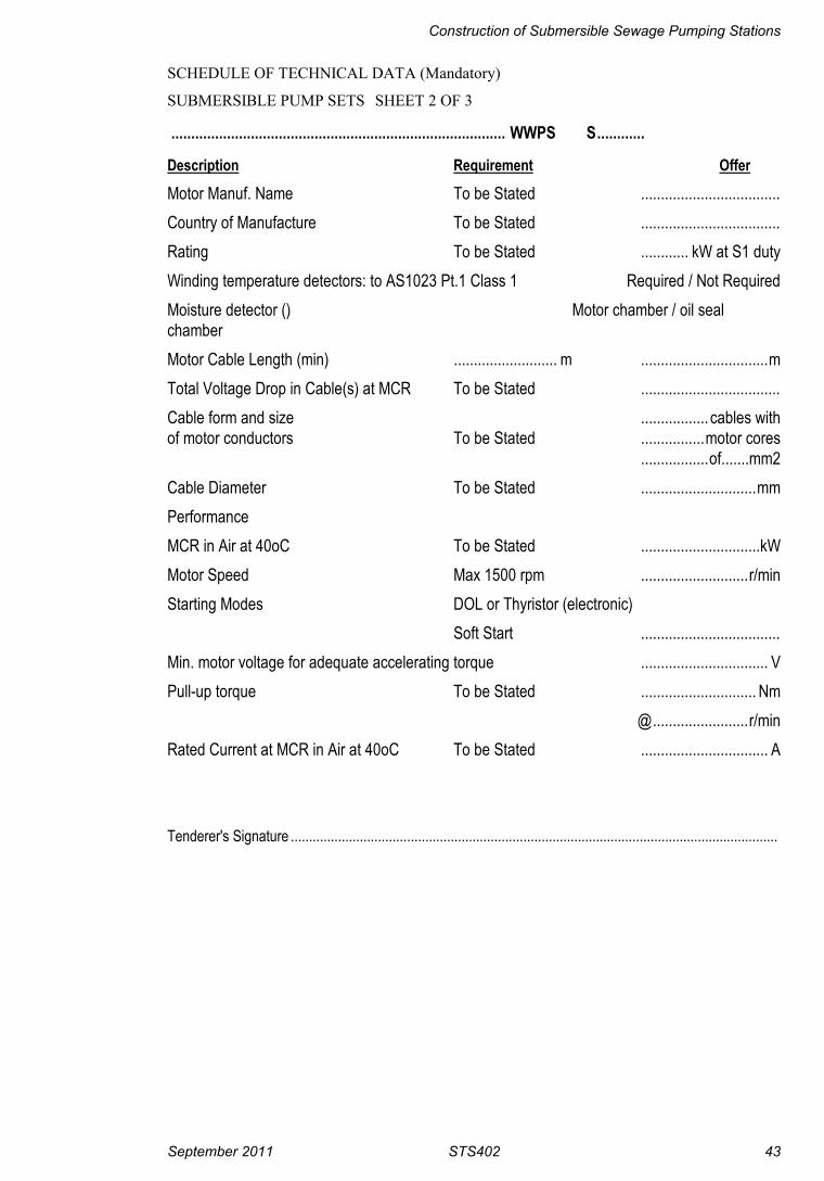
Construction of Submersible Sewage Pumping Stations
September 2011 STS402 43
SCHEDULE OF TECHNICAL DATA (Mandatory)
SUBMERSIBLE PUMP SETS SHEET 2 OF 3
.................................................................................... WWPS S............
Description Requirement Offer
Motor Manuf. Name To be Stated ...................................Country of Manufacture To be Stated ...................................Rating To be Stated ............ kW at S1 dutyWinding temperature detectors: to AS1023 Pt.1 Class 1 Required / Not RequiredMoisture detector () Motor chamber / oil sealchamberMotor Cable Length (min) .......................... m ................................mTotal Voltage Drop in Cable(s) at MCR To be Stated ...................................Cable form and size ................. cables withof motor conductors To be Stated ................motor cores
.................of.......mm2Cable Diameter To be Stated .............................mmPerformanceMCR in Air at 40oC To be Stated ..............................kWMotor Speed Max 1500 rpm ...........................r/minStarting Modes DOL or Thyristor (electronic)
Soft Start ...................................Min. motor voltage for adequate accelerating torque ................................ VPull-up torque To be Stated ............................. Nm
@........................r/minRated Current at MCR in Air at 40oC To be Stated ................................ A
Tenderer's Signature ......................................................................................................................................

Hunter Water Corporation A.B.N. 46 228 513 446
44 STS402 September 2011
SCHEDULE OF TECHNICAL DATA (Mandatory)
SUBMERSIBLE PUMP SETS SHEET 3 OF 3
.................................................................................... WWPS S............
Description Requirement Offer
Locked Rotor Current To be Stated ...................................Loads for which data is required as a 100% 75% 50% 0%% of MCR in air at 40oC. MCR MCR MCR MCREfficiency To be Stated .......... .......... .......... ..........Power Factor To be Stated .......... .......... .......... ..........Current To be Stated .......... .......... .......... ..........Additional Information RequiredPump Set Performance Curves Drawn to AS 1686Head v's flow To be Supplied ( )Pump motor chart : (power input, current, power factor, efficiency) To be Supplied ( )
Tenderer's Signature:......................................................................................................................................
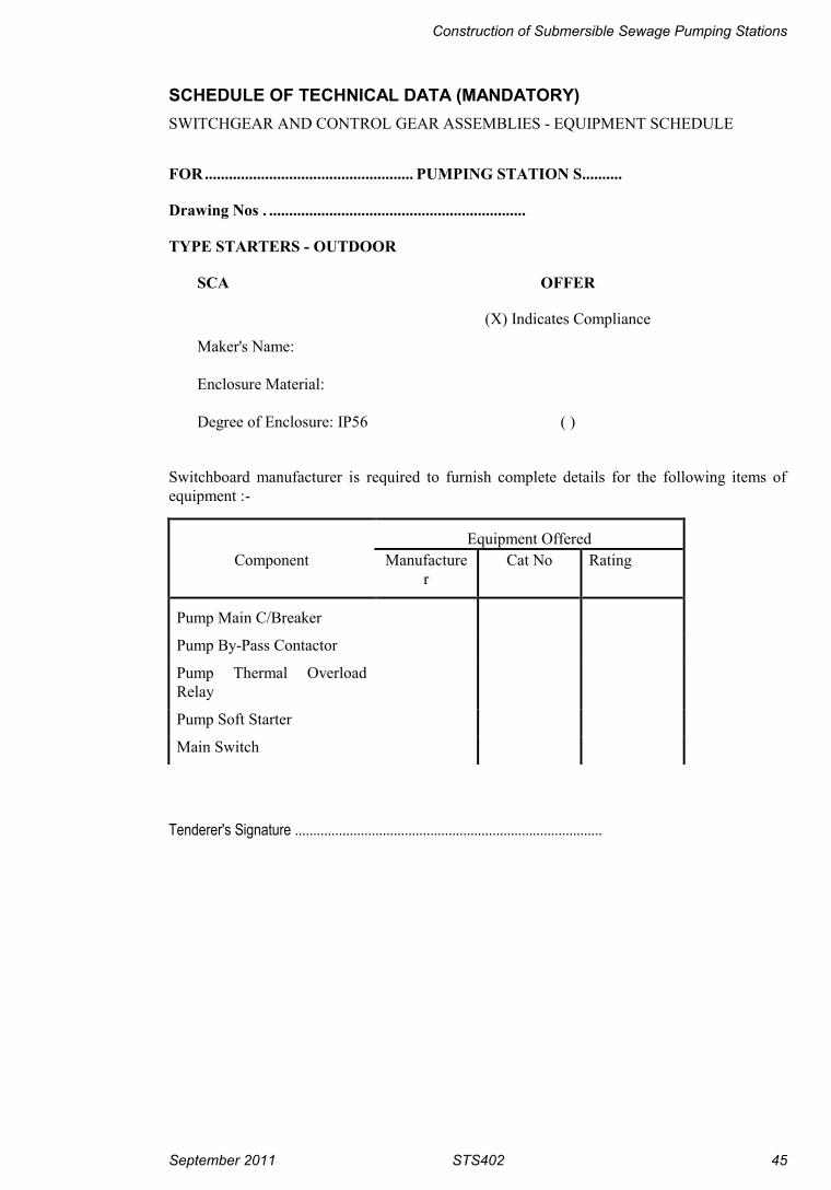
Construction of Submersible Sewage Pumping Stations
September 2011 STS402 45
SCHEDULE OF TECHNICAL DATA (MANDATORY)SWITCHGEAR AND CONTROL GEAR ASSEMBLIES - EQUIPMENT SCHEDULE
FOR.................................................... PUMPING STATION S..........
Drawing Nos . ................................................................
TYPE STARTERS - OUTDOOR
SCA OFFER
(X) Indicates Compliance
Maker's Name:
Enclosure Material:
Degree of Enclosure: IP56 ( )
Switchboard manufacturer is required to furnish complete details for the following items ofequipment :-
Equipment OfferedComponent Manufacture
rCat No Rating
Pump Main C/Breaker
Pump By-Pass Contactor
Pump Thermal OverloadRelay
Pump Soft Starter
Main Switch
Tenderer's Signature ....................................................................................

Hunter Water Corporation A.B.N. 46 228 513 446
46 STS402 September 2011
APPENDIX A - PRE-COMMISSIONING CHECKLISTS
Incorporating
- Mechanical Pre-Commissioning Checklist
- Electrical Pre-Commissioning Checklist
- Control Pre-Commissioning Checklist

Construction of Submersible Sewage Pumping Stations
September 2011 STS402 47
MECHANICALPRE-COMMISSIONING CHECKLIST
STATION:________________________________________________________________
Checked
1 All valves operate from the closed to the fully open position2 All valves seal when closed3 All valves are right handed4 All valves are easy to operate and have no sharp protrusions on hand wheels5 All fasteners and mountings are tightened correctly6 Pump with the lowest serial number (or number../1) installed as Pump 1 (ie nearest
to switchboard)7 Pressure gauge cocks provided on the pump side of each reflux valve and one on the
rising main side8 All pipework within the pump well complete, suitably anchored and guide rails in place9 Gate valves fitted, on the rising main side of the reflux valves with spindles and
handwheels. Knife gate valve on the incoming sewer fitted with extension spindleand stop valve surface box.
10 Specified pump number labels are correctly installed adjacent to the guide rails11 Drop tube and or baffle wall installed (if required)12 Pumps are clear of the batter and well bottom, as per Pump Contractor’s Drawings13 Pump discharge stand supported on grout pads and foundation bolts tight14 No rubbish at the bottom of the well which is likely to damage the pump when it is
started15 With all gate valves shut fill the rising main with water
OK Rectification Required
Comments:
CONTRACTOR’SSIGNATURE: DATE:
HWC REP’SSIGNATURE: DATE:

Hunter Water Corporation A.B.N. 46 228 513 446
48 STS402 September 2011
ELECTRICALPRE-COMMISSIONING CHECKLIST
STATION: ___________________________________________________________________
1. Check that all defects from switchboard inspection have been addressed
2. Electricity supply has been connected and energized. And confirm that a Certificateof Compliance for Electrical Work (CCEW) and associated paperwork has beensupplied
3. Gate valves fitted on the suction to the pumps and the delivery side of the refluxvalves with spindles and hand-wheels
4. Pump with the lowest serial number is installed as Pump 1 (i.e. nearest toswitchboard)
5. Pressure gauge and tapping cocks provided on the suction and delivery pipes6. Specified pump number labels are correctly installed adjacent to the pumps7. With delivery gate valves shut fill the pump casings with water (vent casing)
8. Ensure that all Hatches are fitted with security magnet limit switches as per theHWC standards document STS105
9. “DANGER ELECTRIC” marker bricks installed at ground level and painted yellow10. Earth electrode installed as specified in STS50011. Earth pit, main earth electrode and water service bond installed12. Meter panels are equipped and wired to Supply Authority requirements13. Cable supports within the pump well are correctly located and properly fixed14. No cable stocking has more than one cable installed in it15. Motor cables are supported so as to avoid damage when removing other pump /
pumps16. Motor cables have minimal slack and do not present undue stress on motor cable
glands17. Check that the cable duct cover is held firmly under the edge of the concrete plinth
by the well sliding cover. Also check that it is held firmly under the edge at theswitchboard end.
18. Appropriate lugs fitted to all field cables, and cables correctly identified atterminations
19. Confirm sufficient terminals installed to allow an individual terminal for everyincoming field wire
20. Confirm all field wiring holes are mechanically protected (bushes, sleeves, etc.)21. Motor terminations are in accordance with the connection diagram22. All power cable terminations tested for tightness23. Where parallel cables may be installed on site, provision has been made to ensure
only one cable lug needs to be installed on each side of terminal lug24. SCA rating plate complying with AS 3439 has been fixed25. Confirm motor and pump details displayed on all labels are identical to the
manufacturer’s information. Take a copy of name plate information26. Correct orientation and fixing of the switchboard as per design27. Switchboard plinth and all gland plates sealed28. Check continuity of Earthing system:

Construction of Submersible Sewage Pumping Stations
September 2011 STS402 49
Main EarthWater pipe bondPump 1 connection boxPump 2 connection boxPump 1 MotorPump 2 Motor
29. With all delivery valves closed run pumps to test for leaks in pipe work and valves30. With the motor circuit breakers open and the control isolators off, turn the main
switch on, and check that the supply monitoring relay picks up31. Check operation of phase failure/phase reversal function of the power meter by
removing one phase of supply. Also check by reversing the supply rotation toensure relay does not operate on reversed phase
32. Measure the voltages both phase to phase and phase to neutral. Compare the actualvoltages relative to typical no-load voltage of 400/230V, and the voltage variationbetween phases should be less than 2%
33. Check settings of Starters(VSD or Soft starter)34. If fitted, check operation of by-pass contactor35. Check the motor and pump nameplates for all details and for compliance with the
data shown on the pump rating plate. Take a copy of name plate information
36. Check that the level switches have been adjusted to the required settings and arefunctional
37. Check that level transmitters give an analogue output for the full level range of thedevice. Simulate a pressure/water level of zero to full (or part of) span and checkthe reading on the level display
P1 P238. For the following tests, test for pump 1 & pump 2:E-StopOverloadMotor Thermal ProtectionOther:Check operation of all safety/protective devices for correct operation
39. With the main switch, pump circuit breakers and control isolating switches off,conduct an insulation test with a megometer (megger test) on all motors at 500V.This must give greater than 10 MΩ. Record Results:415 Bus RW WB BW RE WEBE
Pump 1 cables RW WB BW RE WEBE
Pump 2 cables RW WB BW RE WEBE
GPO RE =40. For each pump turn the circuit breaker on and with personnel clear of all pumps,
momentarily turn the control switch to ON and check for correct. Switch pumpcircuit breaker off.
41. Confirm that the Power Meter is configured for CT’s and that the readings on the

Hunter Water Corporation A.B.N. 46 228 513 446
50 STS402 September 2011
local display are appropriate.42. Inspect telemetry and radio supply cable connections for correct polarity43. Measure telemetry supply voltage and back-up battery voltage (should be 13.6V).
Ensure appropriate voltages are detected as per electrical drawings
44. Check for mains voltage rated insulation on data cables where mixed with mainsvoltage cables
45. Check configuration of the PLC I/O against electrical drawings46. Confirm that the telemetry unit has been configured47. Confirm that the RTU calibration certificate has been supplied48. Visual check of antenna installation, clearance from surroundings, mountings
secure, and all cables connectors fitted and taped.
49. Check antenna mounted with weep hole to bottom50. Check antenna bearing and polarization51. Check for secure earth on radio coax surge protection (if applicable) and coax
continuity52. Check radio is marked with frequency in use as per electrical drawings53. Check radio signal strength against fade margin figures54. Check telemetry transmit-level to network device. Set as required by network
device55. Check telemetry receive level from network device, and set as required by the
network device (or if not adjustable, ensure level is below telemetry thresholdlevel)
56. Monitor telemetry messages for errors57. Monitor radio audio clarity and set audio control off or to minimum volume58. Enable SCADA RTU and check telemetry unit is configured correctly59. Check that correct locks are fitted to all cubicles
60. Monitor SCADA poll and error counters for satisfactory operation over a period oftime (to be confirmed with contractor after 7 days, with error rate less than 3%)(SCADA).
OK Rectification Required
Comments:
CONTRACTOR’SSIGNATURE: ………………………. DATE: ……………………….
HWC REP’S SIGNATURE: ………………………. DATE: ……………………….

Construction of Submersible Sewage Pumping Stations
September 2011 STS402 51
APPENDIX B - COMMISSIONING CHECKLISTS
Incorporating
- Pumping Station Data
- Mechanical Commissioning Checklist
- Electrical \Control Commissioning Checklist

Hunter Water Corporation A.B.N. 46 228 513 446
52 STS402 September 2011
PUMPING STATION DATATO BE SUPPLIED WITH COMPLETED COMMISSIONING CHECKLISTS
STATION___________________________________________________________________
Pump Motor
Manufacturer ManufacturerModel Serial NoSerial No Serial NoSerial No Serial NoSerial No Speed rpmFlow L/s Rating kWHead (m) Full Load Current AEfficiency % Locked Rotor Current AImpeller Dia/Code No Load Current AInlet Flange Size (AS 2129) Overload Setting ADischarge Flange Size Insulation Class A(AS 2129)
Seal Failure Detector Details
Type Probe in Oil Yes / NoResistance of Probe Normal Switch State Open / Closed
Thermistor / Thermostat DetailsTo AS 1023.1 Thermistors Fitted Yes / No
Switchboard Incoming Circuit BreakerMake
Voltage Rating kW
Starters
Name Make TypeName Make TypeName Make Type
Main Breakers
Make Rating kWMake Rating kWMake Rating kW
ValvesFunction Type Make SizeFunction Type Make SizeFunction Type Make SizeFunction Type Make Size
PLC Make Model Serial No
Telemetry Make Model Serial No

Construction of Submersible Sewage Pumping Stations
September 2011 STS402 53
MECHANICALCOMMISSIONING CHECKLIST
STATION: ___________________________________________________________________
Checked
1 Check that the pump cables are installed clear of guide rails and not such as to impederemoval of the pumps
2 Lift the pumps on the top slab and check the oil level according to the manufacturer’sinstructions
3 Turn the impellers by hand to ensure they are free to rotate4 Check motor and pump name plate for all details and for compliance with the data
shown on the pump rating plate. Take a copy of name plate information5 Turn the circuit breaker for one pump on and with personnel clear of all pumps,
momentarily turn the control switch to “on” and check for correct rotation asindicated by the arrow on the pump casings and also that the correct pump starts.Switch pump circuit breaker off. Repeat for all the remaining pumps
6 Lower the pumps in the well, checking that they slide smoothly on the guides andsit properly onto the discharge stand
7 Fill the wet well with water to the invert level of the incoming sewer8 With the relevant gate valve open, start one pump in manual mode and check for
leaks, pump/motor vibrationer noise, and that the well level drops9 Shut gate valve and restart pump and check for any leaks in pipework or at the
discharge bend connection
OK Rectification Required
Comments:
CONTRACTOR’SSIGNATURE: DATE:
HWC REP’SSIGNATURE: DATE:

Hunter Water Corporation A.B.N. 46 228 513 446
54 STS402 September 2011

Construction of Submersible Sewage Pumping Stations
September 2011 STS402 55
ELECTRICAL /CONTROL
COMMISSIONING CHECKLIST
STATION:
Electrical / Control Commissioning Checklist Checked
1. Check that all defects from pre-commissioning have been amended
2. Close both pump delivery stop valves
3. Fill the wet well with water to above the high level float4. Turn off main switch.
On the overview page of the SCADA confirm that the POWER changes fromNORMAL to FAIL.And back again when power restored.
P1 P25. In the following test each pump:Turn the pump from OFF to MANUAL.Check that on the SCADA that PUMP MODE changes from OFF to TEST
6. Press the ‘Manual Start’ button.
Check that on the SCADA that PUMP STATUS changes from STOPPED toRUNNING.
7. Turn pump from MANUAL to AUTO.Check that on the SCADA that PUMP MODE changes from TEST to AUTO.NB: Pump may stop if not called by the controller.
8. Turn pump from AUTO to OFF.Check that PUMP MODE change to OFF and PUMP STATUS changes (oralready has changed) back to STOPPED.
9. From the SCADA terminal initiate PUMP INHIBIT on the pump.Ensure that the pump will not operate, and that the “PLC Inhibit” lamp is ON.Turn the PUMP INHIBIT off and check that both pumps operate and that the“PLC Inhibit” lamp is OFF.
10. Operate the “Emergency-Stop” push button.
Ensure that the pump becomes unavailable on the SCADA & the “DriveFault” lamp is ON.
Then release the “Emergency-Stop” push button, switch the pump to OFF,then AUTO, and ensure the pump returns to available & the lamp is OFF.
11. Bridge out terminals for the seal fail probe on the pump until the seal failrelay is activated (may be referred to as “Pump Warning Healthy”).
Check that on the SCADA PUMP WARNING changes from NORMAL toALARM (FAIL) & the “Pump Warning” lamp is ON.
Reset the relay and check that PUMP WARNING returns to NORMAL & the“Pump Warning” lamp is OFF.
NB: This will not trip the pump.
12. Test operation of overload relay by winding down trip point.
Check that on the SCADA that the pump becomes unavailable and the pumpstatus is FAILED & the “Drive Fault” lamp is ON.
Reset the relay. Reset the alarm condition reset by pump inhibit OR switch

Hunter Water Corporation A.B.N. 46 228 513 446
56 STS402 September 2011
Electrical / Control Commissioning Checklist Checked
pump to Off, then Auto. Check Alarm clears.
13. If Power Factor Correction and a PFC contactor is installed, ensure theBypass contactor is not energised. Bridge out terminals for the Power FactorCorrection contact on the drive (for more than 2 seconds).
Ensure that the pump becomes unavailable, and check that on the SCADA thePFC failed alarm is raised & the “Drive Fault” lamp is ON.
Reset the relay. Reset the alarm condition reset by SCADA inhibit OR switchpump to Off, then Auto.
14. On the soft starter set the current limit down to minimum and start the drive.
The Soft start fault input will then be detected and the drive will becomeunavailable.
Check that on the SCADA the Soft Starter status changes from NORMAL toALARM & the “Drive Fault” lamp is ON.
Return limit setting to normal. Reset the alarm condition reset by pumpinhibit OR switch pump to Off, then Auto. Check that Soft Starter statusreturns to NORMAL & the “Drive Fault” lamp is OFF.
15. Using a manual trip on the pump temperature sensor relay (may be referred toas “Pump Protection”).
Ensure that the drive trips and becomes unavailable on the SCADA, andcheck that the “Pump Fault” lamp is ON.
Remove the trip condition and reset by pump inhibit OR switch pump to Off,then Auto
16. Removing the 24vdc control fuse for the drive and ensure that the drivecannot start in automatic or Test
17. Ensure Level Control Override push button calls Level 1.
18. While pumps are running.
Check that the correct pump current readings are recorded in the SCADA.
19. Check on the SCADA that Pump Hours Run is calculated and displayedcorrectly. NB: Change clock on PLC to test as value resets at 8am.
20. Check on the SCADA that Pump Starts for the previous hour is calculatedand displayed correctly.
21. Ensure that an appropriate “Fail to Start” time has been entered. Remove thePump Start feedback from PLC and call the pump to run in Auto.
After the “Fail to Start” time, ensure that an Alarm is raised, and the pump isFAILED & the “Drive Fault” lamp is ON.
Reset the relay. Reset the alarm condition reset by pump inhibit OR switchpump to Off, then Auto. Check that the pump is no longer FAILED & the“Drive Fault” lamp is OFF.
22. After a pump has run for 20 seconds, check that the instantaneous power andpower factor (red phase) is measured and displayed correctly in the SCADA.
23. Simulate control levels by raising and lowering the hydrostatic level probe inthe well.Check that the level shown is accurate.Also check on the SCADA that the WELL DISPLAY and WELL

Construction of Submersible Sewage Pumping Stations
September 2011 STS402 57
Electrical / Control Commissioning Checklist Checked
PERCENTAGE are filling to the appropriate level.
24. Check that the pumps are cutting in and out at the correct levels.
Also check on the SCADA that LEVEL 1 and LEVEL 2 are becomingSELECTED at the correct percentage full.
NB: The PLC uses 30 seconds de-bounce timer on Cutin levels & 5 secondsfor Cutouts.
25. Lift wet well high alarm float switch out of the well and hold upside down.Check on SCADA that WET WELL changes from NORMAL to FLOODED.After 30 seconds, ensure that Level 2 is called.Place the float switch back in the well (wait 5 seconds) and check that theWET WELL reverts back to NORMAL.Wait 90 seconds, and then ensure station operates as per the present analoglevel instrument level control.
26. From the SCADA terminal initiate a STATION INHIBIT.Check that no pumps can operate in auto whilst the STATION INHIBIT isoperational and that the “PLC Inhibit” lamp is ON.Turn the STATION INHIBIT off.Check that both pumps operate and that the “PLC Inhibit” lamp is OFF.
27. By raising the level probe simulate a level below lead cut-in and above leadcut-out.From the SCADA terminal initiate a STATION START check that pumpsstart.
28. Ensure the lead pump is changed over each time a pump runs (Lead PumpChangeover)
29. Test all PLC inputs from drive equipment. Test all PLC outputs to driveequipment Test each “press to test” indicating lamp
30. Bridge out terminals for the Generator Selected contact.
Ensure that only one pump is permitted to run.
Check that on the SCADA the Generator Supply status changes from OFF toSELECTED. NB: There are no alarms.
Return the Generator Selected contact to normal
31. Check that on the SCADA the Surge Diverter alarm changes from NORMALto ALARM.
Return the Surge Diverter Healthy contact to normal32. Close all hatches and J/Box doors.
Check on SCADA that the SECURITY changes from ALARM to NORMAL.Then operate each individual door and hatch to operate the station securityalarm. (This can be monitored from the PLC input “Field Secure”)
33. Close all switchboard and cubicle doors.Check on SCADA that the SECURITY changes from ALARM to NORMAL.Then operate each individual door to operate the station security alarm. (Thiscan be monitored from the PLC input “Switchboard Secure”)
34. Test Duty Queue
35. Check on the SCADA that “Start Station” button will call level 1.
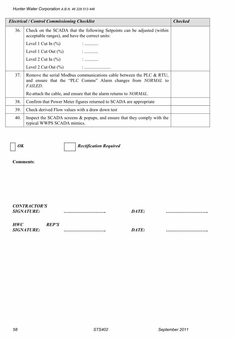
Hunter Water Corporation A.B.N. 46 228 513 446
58 STS402 September 2011
Electrical / Control Commissioning Checklist Checked
36. Check on the SCADA that the following Setpoints can be adjusted (withinacceptable ranges), and have the correct units:
Level 1 Cut In (%) : ............
Level 1 Cut Out (%) : ............
Level 2 Cut In (%) : ............
Level 2 Cut Out (%) : .......................
37. Remove the serial Modbus communications cable between the PLC & RTU,and ensure that the “PLC Comms” Alarm changes from NORMAL toFAILED.
Re-attach the cable, and ensure that the alarm returns to NORMAL.
38. Confirm that Power Meter figures returned to SCADA are appropriate
39. Check derived Flow values with a draw down test
40. Inspect the SCADA screens & popups, and ensure that they comply with thetypical WWPS SCADA mimics.
OK Rectification Required
Comments:
CONTRACTOR’SSIGNATURE: ………………………. DATE: ……………………….
HWC REP’SSIGNATURE: ………………………. DATE: ……………………….
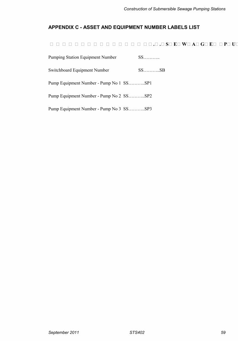
Construction of Submersible Sewage Pumping Stations
September 2011 STS402 59
APPENDIX C - ASSET AND EQUIPMENT NUMBER LABELS LIST
…………………………………………..SEWAGE PUMPING STATION S…….
Pumping Station Equipment Number SS………..
Switchboard Equipment Number SS………..SB
Pump Equipment Number - Pump No 1 SS………..SP1
Pump Equipment Number - Pump No 2 SS………..SP2
Pump Equipment Number - Pump No 3 SS………..SP3

Hunter Water Corporation A.B.N. 46 228 513 446
60 STS402 September 2011
APPENDIX D - PIPELINE CHARACTERISTIC CURVES

Construction of Submersible Sewage Pumping Stations
September 2011 STS402 61
APPENDIX E - BORE LOGS
[END OF STS402]